US20190201047A1 - Method for smart energy device infrastructure - Google Patents
Method for smart energy device infrastructure Download PDFInfo
- Publication number
- US20190201047A1 US20190201047A1 US16/209,458 US201816209458A US2019201047A1 US 20190201047 A1 US20190201047 A1 US 20190201047A1 US 201816209458 A US201816209458 A US 201816209458A US 2019201047 A1 US2019201047 A1 US 2019201047A1
- Authority
- US
- United States
- Prior art keywords
- control circuit
- ultrasonic
- surgical
- impedance value
- ultrasonic transducer
- Prior art date
- Legal status (The legal status is an assumption and is not a legal conclusion. Google has not performed a legal analysis and makes no representation as to the accuracy of the status listed.)
- Granted
Links
Images


Classifications
-
- A—HUMAN NECESSITIES
- A61—MEDICAL OR VETERINARY SCIENCE; HYGIENE
- A61B—DIAGNOSIS; SURGERY; IDENTIFICATION
- A61B1/00—Instruments for performing medical examinations of the interior of cavities or tubes of the body by visual or photographical inspection, e.g. endoscopes; Illuminating arrangements therefor
- A61B1/00002—Operational features of endoscopes
- A61B1/00004—Operational features of endoscopes characterised by electronic signal processing
- A61B1/00009—Operational features of endoscopes characterised by electronic signal processing of image signals during a use of endoscope
- A61B1/000094—Operational features of endoscopes characterised by electronic signal processing of image signals during a use of endoscope extracting biological structures
-
- A—HUMAN NECESSITIES
- A61—MEDICAL OR VETERINARY SCIENCE; HYGIENE
- A61B—DIAGNOSIS; SURGERY; IDENTIFICATION
- A61B1/00—Instruments for performing medical examinations of the interior of cavities or tubes of the body by visual or photographical inspection, e.g. endoscopes; Illuminating arrangements therefor
- A61B1/00002—Operational features of endoscopes
- A61B1/00004—Operational features of endoscopes characterised by electronic signal processing
- A61B1/00009—Operational features of endoscopes characterised by electronic signal processing of image signals during a use of endoscope
- A61B1/000096—Operational features of endoscopes characterised by electronic signal processing of image signals during a use of endoscope using artificial intelligence
-
- A—HUMAN NECESSITIES
- A61—MEDICAL OR VETERINARY SCIENCE; HYGIENE
- A61B—DIAGNOSIS; SURGERY; IDENTIFICATION
- A61B17/00—Surgical instruments, devices or methods
- A61B17/068—Surgical staplers, e.g. containing multiple staples or clamps
- A61B17/0682—Surgical staplers, e.g. containing multiple staples or clamps for applying U-shaped staples or clamps, e.g. without a forming anvil
-
- A—HUMAN NECESSITIES
- A61—MEDICAL OR VETERINARY SCIENCE; HYGIENE
- A61B—DIAGNOSIS; SURGERY; IDENTIFICATION
- A61B17/00—Surgical instruments, devices or methods
- A61B17/068—Surgical staplers, e.g. containing multiple staples or clamps
- A61B17/072—Surgical staplers, e.g. containing multiple staples or clamps for applying a row of staples in a single action, e.g. the staples being applied simultaneously
- A61B17/07207—Surgical staplers, e.g. containing multiple staples or clamps for applying a row of staples in a single action, e.g. the staples being applied simultaneously the staples being applied sequentially
-
- A—HUMAN NECESSITIES
- A61—MEDICAL OR VETERINARY SCIENCE; HYGIENE
- A61B—DIAGNOSIS; SURGERY; IDENTIFICATION
- A61B17/00—Surgical instruments, devices or methods
- A61B17/11—Surgical instruments, devices or methods for performing anastomosis; Buttons for anastomosis
- A61B17/1114—Surgical instruments, devices or methods for performing anastomosis; Buttons for anastomosis of the digestive tract, e.g. bowels or oesophagus
-
- A—HUMAN NECESSITIES
- A61—MEDICAL OR VETERINARY SCIENCE; HYGIENE
- A61B—DIAGNOSIS; SURGERY; IDENTIFICATION
- A61B17/00—Surgical instruments, devices or methods
- A61B17/11—Surgical instruments, devices or methods for performing anastomosis; Buttons for anastomosis
- A61B17/115—Staplers for performing anastomosis, e.g. in a single operation
- A61B17/1155—Circular staplers comprising a plurality of staples
-
- A—HUMAN NECESSITIES
- A61—MEDICAL OR VETERINARY SCIENCE; HYGIENE
- A61B—DIAGNOSIS; SURGERY; IDENTIFICATION
- A61B17/00—Surgical instruments, devices or methods
- A61B17/12—Surgical instruments, devices or methods for ligaturing or otherwise compressing tubular parts of the body, e.g. blood vessels or umbilical cord
- A61B17/128—Surgical instruments, devices or methods for ligaturing or otherwise compressing tubular parts of the body, e.g. blood vessels or umbilical cord for applying or removing clamps or clips
- A61B17/1285—Surgical instruments, devices or methods for ligaturing or otherwise compressing tubular parts of the body, e.g. blood vessels or umbilical cord for applying or removing clamps or clips for minimally invasive surgery
-
- A—HUMAN NECESSITIES
- A61—MEDICAL OR VETERINARY SCIENCE; HYGIENE
- A61B—DIAGNOSIS; SURGERY; IDENTIFICATION
- A61B17/00—Surgical instruments, devices or methods
- A61B17/28—Surgical forceps
- A61B17/2812—Surgical forceps with a single pivotal connection
- A61B17/2833—Locking means
-
- A—HUMAN NECESSITIES
- A61—MEDICAL OR VETERINARY SCIENCE; HYGIENE
- A61B—DIAGNOSIS; SURGERY; IDENTIFICATION
- A61B17/00—Surgical instruments, devices or methods
- A61B17/28—Surgical forceps
- A61B17/285—Surgical forceps combined with cutting implements
-
- A—HUMAN NECESSITIES
- A61—MEDICAL OR VETERINARY SCIENCE; HYGIENE
- A61B—DIAGNOSIS; SURGERY; IDENTIFICATION
- A61B17/00—Surgical instruments, devices or methods
- A61B17/32—Surgical cutting instruments
- A61B17/320068—Surgical cutting instruments using mechanical vibrations, e.g. ultrasonic
-
- A—HUMAN NECESSITIES
- A61—MEDICAL OR VETERINARY SCIENCE; HYGIENE
- A61B—DIAGNOSIS; SURGERY; IDENTIFICATION
- A61B17/00—Surgical instruments, devices or methods
- A61B17/32—Surgical cutting instruments
- A61B17/320068—Surgical cutting instruments using mechanical vibrations, e.g. ultrasonic
- A61B17/320092—Surgical cutting instruments using mechanical vibrations, e.g. ultrasonic with additional movable means for clamping or cutting tissue, e.g. with a pivoting jaw
-
- A—HUMAN NECESSITIES
- A61—MEDICAL OR VETERINARY SCIENCE; HYGIENE
- A61B—DIAGNOSIS; SURGERY; IDENTIFICATION
- A61B18/00—Surgical instruments, devices or methods for transferring non-mechanical forms of energy to or from the body
- A61B18/04—Surgical instruments, devices or methods for transferring non-mechanical forms of energy to or from the body by heating
- A61B18/12—Surgical instruments, devices or methods for transferring non-mechanical forms of energy to or from the body by heating by passing a current through the tissue to be heated, e.g. high-frequency current
- A61B18/14—Probes or electrodes therefor
- A61B18/1442—Probes having pivoting end effectors, e.g. forceps
- A61B18/1445—Probes having pivoting end effectors, e.g. forceps at the distal end of a shaft, e.g. forceps or scissors at the end of a rigid rod
-
- A—HUMAN NECESSITIES
- A61—MEDICAL OR VETERINARY SCIENCE; HYGIENE
- A61B—DIAGNOSIS; SURGERY; IDENTIFICATION
- A61B34/00—Computer-aided surgery; Manipulators or robots specially adapted for use in surgery
- A61B34/20—Surgical navigation systems; Devices for tracking or guiding surgical instruments, e.g. for frameless stereotaxis
-
- A—HUMAN NECESSITIES
- A61—MEDICAL OR VETERINARY SCIENCE; HYGIENE
- A61B—DIAGNOSIS; SURGERY; IDENTIFICATION
- A61B34/00—Computer-aided surgery; Manipulators or robots specially adapted for use in surgery
- A61B34/30—Surgical robots
- A61B34/32—Surgical robots operating autonomously
-
- A—HUMAN NECESSITIES
- A61—MEDICAL OR VETERINARY SCIENCE; HYGIENE
- A61B—DIAGNOSIS; SURGERY; IDENTIFICATION
- A61B34/00—Computer-aided surgery; Manipulators or robots specially adapted for use in surgery
- A61B34/70—Manipulators specially adapted for use in surgery
- A61B34/71—Manipulators operated by drive cable mechanisms
-
- A—HUMAN NECESSITIES
- A61—MEDICAL OR VETERINARY SCIENCE; HYGIENE
- A61B—DIAGNOSIS; SURGERY; IDENTIFICATION
- A61B5/00—Measuring for diagnostic purposes; Identification of persons
- A61B5/0059—Measuring for diagnostic purposes; Identification of persons using light, e.g. diagnosis by transillumination, diascopy, fluorescence
- A61B5/0062—Arrangements for scanning
- A61B5/0066—Optical coherence imaging
-
- A—HUMAN NECESSITIES
- A61—MEDICAL OR VETERINARY SCIENCE; HYGIENE
- A61B—DIAGNOSIS; SURGERY; IDENTIFICATION
- A61B5/00—Measuring for diagnostic purposes; Identification of persons
- A61B5/0059—Measuring for diagnostic purposes; Identification of persons using light, e.g. diagnosis by transillumination, diascopy, fluorescence
- A61B5/0075—Measuring for diagnostic purposes; Identification of persons using light, e.g. diagnosis by transillumination, diascopy, fluorescence by spectroscopy, i.e. measuring spectra, e.g. Raman spectroscopy, infrared absorption spectroscopy
-
- A—HUMAN NECESSITIES
- A61—MEDICAL OR VETERINARY SCIENCE; HYGIENE
- A61B—DIAGNOSIS; SURGERY; IDENTIFICATION
- A61B5/00—Measuring for diagnostic purposes; Identification of persons
- A61B5/02—Detecting, measuring or recording for evaluating the cardiovascular system, e.g. pulse, heart rate, blood pressure or blood flow
- A61B5/026—Measuring blood flow
- A61B5/0261—Measuring blood flow using optical means, e.g. infrared light
-
- A—HUMAN NECESSITIES
- A61—MEDICAL OR VETERINARY SCIENCE; HYGIENE
- A61B—DIAGNOSIS; SURGERY; IDENTIFICATION
- A61B6/00—Apparatus or devices for radiation diagnosis; Apparatus or devices for radiation diagnosis combined with radiation therapy equipment
- A61B6/52—Devices using data or image processing specially adapted for radiation diagnosis
- A61B6/5211—Devices using data or image processing specially adapted for radiation diagnosis involving processing of medical diagnostic data
- A61B6/5229—Devices using data or image processing specially adapted for radiation diagnosis involving processing of medical diagnostic data combining image data of a patient, e.g. combining a functional image with an anatomical image
- A61B6/5247—Devices using data or image processing specially adapted for radiation diagnosis involving processing of medical diagnostic data combining image data of a patient, e.g. combining a functional image with an anatomical image combining images from an ionising-radiation diagnostic technique and a non-ionising radiation diagnostic technique, e.g. X-ray and ultrasound
-
- A—HUMAN NECESSITIES
- A61—MEDICAL OR VETERINARY SCIENCE; HYGIENE
- A61B—DIAGNOSIS; SURGERY; IDENTIFICATION
- A61B90/00—Instruments, implements or accessories specially adapted for surgery or diagnosis and not covered by any of the groups A61B1/00 - A61B50/00, e.g. for luxation treatment or for protecting wound edges
- A61B90/30—Devices for illuminating a surgical field, the devices having an interrelation with other surgical devices or with a surgical procedure
- A61B90/35—Supports therefor
-
- A—HUMAN NECESSITIES
- A61—MEDICAL OR VETERINARY SCIENCE; HYGIENE
- A61B—DIAGNOSIS; SURGERY; IDENTIFICATION
- A61B90/00—Instruments, implements or accessories specially adapted for surgery or diagnosis and not covered by any of the groups A61B1/00 - A61B50/00, e.g. for luxation treatment or for protecting wound edges
- A61B90/36—Image-producing devices or illumination devices not otherwise provided for
- A61B90/361—Image-producing devices, e.g. surgical cameras
-
- A—HUMAN NECESSITIES
- A61—MEDICAL OR VETERINARY SCIENCE; HYGIENE
- A61M—DEVICES FOR INTRODUCING MEDIA INTO, OR ONTO, THE BODY; DEVICES FOR TRANSDUCING BODY MEDIA OR FOR TAKING MEDIA FROM THE BODY; DEVICES FOR PRODUCING OR ENDING SLEEP OR STUPOR
- A61M1/00—Suction or pumping devices for medical purposes; Devices for carrying-off, for treatment of, or for carrying-over, body-liquids; Drainage systems
- A61M1/71—Suction drainage systems
- A61M1/73—Suction drainage systems comprising sensors or indicators for physical values
-
- A—HUMAN NECESSITIES
- A61—MEDICAL OR VETERINARY SCIENCE; HYGIENE
- A61M—DEVICES FOR INTRODUCING MEDIA INTO, OR ONTO, THE BODY; DEVICES FOR TRANSDUCING BODY MEDIA OR FOR TAKING MEDIA FROM THE BODY; DEVICES FOR PRODUCING OR ENDING SLEEP OR STUPOR
- A61M1/00—Suction or pumping devices for medical purposes; Devices for carrying-off, for treatment of, or for carrying-over, body-liquids; Drainage systems
- A61M1/71—Suction drainage systems
- A61M1/79—Filters for solid matter
-
- B—PERFORMING OPERATIONS; TRANSPORTING
- B25—HAND TOOLS; PORTABLE POWER-DRIVEN TOOLS; MANIPULATORS
- B25J—MANIPULATORS; CHAMBERS PROVIDED WITH MANIPULATION DEVICES
- B25J13/00—Controls for manipulators
- B25J13/006—Controls for manipulators by means of a wireless system for controlling one or several manipulators
-
- B—PERFORMING OPERATIONS; TRANSPORTING
- B25—HAND TOOLS; PORTABLE POWER-DRIVEN TOOLS; MANIPULATORS
- B25J—MANIPULATORS; CHAMBERS PROVIDED WITH MANIPULATION DEVICES
- B25J9/00—Program-controlled manipulators
- B25J9/16—Program controls
- B25J9/1694—Program controls characterised by use of sensors other than normal servo-feedback from position, speed or acceleration sensors, perception control, multi-sensor controlled systems, sensor fusion
- B25J9/1697—Vision controlled systems
-
- G—PHYSICS
- G06—COMPUTING OR CALCULATING; COUNTING
- G06K—GRAPHICAL DATA READING; PRESENTATION OF DATA; RECORD CARRIERS; HANDLING RECORD CARRIERS
- G06K19/00—Record carriers for use with machines and with at least a part designed to carry digital markings
- G06K19/06—Record carriers for use with machines and with at least a part designed to carry digital markings characterised by the kind of the digital marking, e.g. shape, nature, code
- G06K19/067—Record carriers with conductive marks, printed circuits or semiconductor circuit elements, e.g. credit or identity cards also with resonating or responding marks without active components
- G06K19/07—Record carriers with conductive marks, printed circuits or semiconductor circuit elements, e.g. credit or identity cards also with resonating or responding marks without active components with integrated circuit chips
- G06K19/077—Constructional details, e.g. mounting of circuits in the carrier
- G06K19/07749—Constructional details, e.g. mounting of circuits in the carrier the record carrier being capable of non-contact communication, e.g. constructional details of the antenna of a non-contact smart card
-
- G—PHYSICS
- G06—COMPUTING OR CALCULATING; COUNTING
- G06K—GRAPHICAL DATA READING; PRESENTATION OF DATA; RECORD CARRIERS; HANDLING RECORD CARRIERS
- G06K7/00—Methods or arrangements for sensing record carriers, e.g. for reading patterns
- G06K7/10—Methods or arrangements for sensing record carriers, e.g. for reading patterns by electromagnetic radiation, e.g. optical sensing; by corpuscular radiation
- G06K7/10009—Methods or arrangements for sensing record carriers, e.g. for reading patterns by electromagnetic radiation, e.g. optical sensing; by corpuscular radiation sensing by radiation using wavelengths larger than 0.1 mm, e.g. radio-waves or microwaves
- G06K7/10316—Methods or arrangements for sensing record carriers, e.g. for reading patterns by electromagnetic radiation, e.g. optical sensing; by corpuscular radiation sensing by radiation using wavelengths larger than 0.1 mm, e.g. radio-waves or microwaves using at least one antenna particularly designed for interrogating the wireless record carriers
-
- G—PHYSICS
- G16—INFORMATION AND COMMUNICATION TECHNOLOGY [ICT] SPECIALLY ADAPTED FOR SPECIFIC APPLICATION FIELDS
- G16H—HEALTHCARE INFORMATICS, i.e. INFORMATION AND COMMUNICATION TECHNOLOGY [ICT] SPECIALLY ADAPTED FOR THE HANDLING OR PROCESSING OF MEDICAL OR HEALTHCARE DATA
- G16H10/00—ICT specially adapted for the handling or processing of patient-related medical or healthcare data
- G16H10/60—ICT specially adapted for the handling or processing of patient-related medical or healthcare data for patient-specific data, e.g. for electronic patient records
-
- G—PHYSICS
- G16—INFORMATION AND COMMUNICATION TECHNOLOGY [ICT] SPECIALLY ADAPTED FOR SPECIFIC APPLICATION FIELDS
- G16H—HEALTHCARE INFORMATICS, i.e. INFORMATION AND COMMUNICATION TECHNOLOGY [ICT] SPECIALLY ADAPTED FOR THE HANDLING OR PROCESSING OF MEDICAL OR HEALTHCARE DATA
- G16H30/00—ICT specially adapted for the handling or processing of medical images
- G16H30/20—ICT specially adapted for the handling or processing of medical images for handling medical images, e.g. DICOM, HL7 or PACS
-
- G—PHYSICS
- G16—INFORMATION AND COMMUNICATION TECHNOLOGY [ICT] SPECIALLY ADAPTED FOR SPECIFIC APPLICATION FIELDS
- G16H—HEALTHCARE INFORMATICS, i.e. INFORMATION AND COMMUNICATION TECHNOLOGY [ICT] SPECIALLY ADAPTED FOR THE HANDLING OR PROCESSING OF MEDICAL OR HEALTHCARE DATA
- G16H40/00—ICT specially adapted for the management or administration of healthcare resources or facilities; ICT specially adapted for the management or operation of medical equipment or devices
- G16H40/40—ICT specially adapted for the management or administration of healthcare resources or facilities; ICT specially adapted for the management or operation of medical equipment or devices for the management of medical equipment or devices, e.g. scheduling maintenance or upgrades
-
- G—PHYSICS
- G16—INFORMATION AND COMMUNICATION TECHNOLOGY [ICT] SPECIALLY ADAPTED FOR SPECIFIC APPLICATION FIELDS
- G16H—HEALTHCARE INFORMATICS, i.e. INFORMATION AND COMMUNICATION TECHNOLOGY [ICT] SPECIALLY ADAPTED FOR THE HANDLING OR PROCESSING OF MEDICAL OR HEALTHCARE DATA
- G16H40/00—ICT specially adapted for the management or administration of healthcare resources or facilities; ICT specially adapted for the management or operation of medical equipment or devices
- G16H40/60—ICT specially adapted for the management or administration of healthcare resources or facilities; ICT specially adapted for the management or operation of medical equipment or devices for the operation of medical equipment or devices
- G16H40/63—ICT specially adapted for the management or administration of healthcare resources or facilities; ICT specially adapted for the management or operation of medical equipment or devices for the operation of medical equipment or devices for local operation
-
- G—PHYSICS
- G16—INFORMATION AND COMMUNICATION TECHNOLOGY [ICT] SPECIALLY ADAPTED FOR SPECIFIC APPLICATION FIELDS
- G16H—HEALTHCARE INFORMATICS, i.e. INFORMATION AND COMMUNICATION TECHNOLOGY [ICT] SPECIALLY ADAPTED FOR THE HANDLING OR PROCESSING OF MEDICAL OR HEALTHCARE DATA
- G16H40/00—ICT specially adapted for the management or administration of healthcare resources or facilities; ICT specially adapted for the management or operation of medical equipment or devices
- G16H40/60—ICT specially adapted for the management or administration of healthcare resources or facilities; ICT specially adapted for the management or operation of medical equipment or devices for the operation of medical equipment or devices
- G16H40/67—ICT specially adapted for the management or administration of healthcare resources or facilities; ICT specially adapted for the management or operation of medical equipment or devices for the operation of medical equipment or devices for remote operation
-
- G—PHYSICS
- G16—INFORMATION AND COMMUNICATION TECHNOLOGY [ICT] SPECIALLY ADAPTED FOR SPECIFIC APPLICATION FIELDS
- G16H—HEALTHCARE INFORMATICS, i.e. INFORMATION AND COMMUNICATION TECHNOLOGY [ICT] SPECIALLY ADAPTED FOR THE HANDLING OR PROCESSING OF MEDICAL OR HEALTHCARE DATA
- G16H50/00—ICT specially adapted for medical diagnosis, medical simulation or medical data mining; ICT specially adapted for detecting, monitoring or modelling epidemics or pandemics
- G16H50/20—ICT specially adapted for medical diagnosis, medical simulation or medical data mining; ICT specially adapted for detecting, monitoring or modelling epidemics or pandemics for computer-aided diagnosis, e.g. based on medical expert systems
-
- G—PHYSICS
- G16—INFORMATION AND COMMUNICATION TECHNOLOGY [ICT] SPECIALLY ADAPTED FOR SPECIFIC APPLICATION FIELDS
- G16H—HEALTHCARE INFORMATICS, i.e. INFORMATION AND COMMUNICATION TECHNOLOGY [ICT] SPECIALLY ADAPTED FOR THE HANDLING OR PROCESSING OF MEDICAL OR HEALTHCARE DATA
- G16H50/00—ICT specially adapted for medical diagnosis, medical simulation or medical data mining; ICT specially adapted for detecting, monitoring or modelling epidemics or pandemics
- G16H50/70—ICT specially adapted for medical diagnosis, medical simulation or medical data mining; ICT specially adapted for detecting, monitoring or modelling epidemics or pandemics for mining of medical data, e.g. analysing previous cases of other patients
-
- G—PHYSICS
- G16—INFORMATION AND COMMUNICATION TECHNOLOGY [ICT] SPECIALLY ADAPTED FOR SPECIFIC APPLICATION FIELDS
- G16H—HEALTHCARE INFORMATICS, i.e. INFORMATION AND COMMUNICATION TECHNOLOGY [ICT] SPECIALLY ADAPTED FOR THE HANDLING OR PROCESSING OF MEDICAL OR HEALTHCARE DATA
- G16H70/00—ICT specially adapted for the handling or processing of medical references
- G16H70/20—ICT specially adapted for the handling or processing of medical references relating to practices or guidelines
-
- H—ELECTRICITY
- H01—ELECTRIC ELEMENTS
- H01Q—ANTENNAS, i.e. RADIO AERIALS
- H01Q1/00—Details of, or arrangements associated with, antennas
- H01Q1/12—Supports; Mounting means
- H01Q1/22—Supports; Mounting means by structural association with other equipment or articles
-
- H—ELECTRICITY
- H04—ELECTRIC COMMUNICATION TECHNIQUE
- H04L—TRANSMISSION OF DIGITAL INFORMATION, e.g. TELEGRAPHIC COMMUNICATION
- H04L63/00—Network architectures or network communication protocols for network security
- H04L63/14—Network architectures or network communication protocols for network security for detecting or protecting against malicious traffic
- H04L63/1408—Network architectures or network communication protocols for network security for detecting or protecting against malicious traffic by monitoring network traffic
- H04L63/1416—Event detection, e.g. attack signature detection
-
- H—ELECTRICITY
- H04—ELECTRIC COMMUNICATION TECHNIQUE
- H04L—TRANSMISSION OF DIGITAL INFORMATION, e.g. TELEGRAPHIC COMMUNICATION
- H04L67/00—Network arrangements or protocols for supporting network services or applications
- H04L67/01—Protocols
- H04L67/12—Protocols specially adapted for proprietary or special-purpose networking environments, e.g. medical networks, sensor networks, networks in vehicles or remote metering networks
-
- H—ELECTRICITY
- H04—ELECTRIC COMMUNICATION TECHNIQUE
- H04N—PICTORIAL COMMUNICATION, e.g. TELEVISION
- H04N23/00—Cameras or camera modules comprising electronic image sensors; Control thereof
- H04N23/50—Constructional details
- H04N23/555—Constructional details for picking-up images in sites, inaccessible due to their dimensions or hazardous conditions, e.g. endoscopes or borescopes
-
- H—ELECTRICITY
- H04—ELECTRIC COMMUNICATION TECHNIQUE
- H04N—PICTORIAL COMMUNICATION, e.g. TELEVISION
- H04N5/00—Details of television systems
- H04N5/222—Studio circuitry; Studio devices; Studio equipment
- H04N5/262—Studio circuits, e.g. for mixing, switching-over, change of character of image, other special effects ; Cameras specially adapted for the electronic generation of special effects
- H04N5/272—Means for inserting a foreground image in a background image, i.e. inlay, outlay
-
- H—ELECTRICITY
- H04—ELECTRIC COMMUNICATION TECHNIQUE
- H04N—PICTORIAL COMMUNICATION, e.g. TELEVISION
- H04N7/00—Television systems
- H04N7/18—Closed-circuit television [CCTV] systems, i.e. systems in which the video signal is not broadcast
- H04N7/183—Closed-circuit television [CCTV] systems, i.e. systems in which the video signal is not broadcast for receiving images from a single remote source
-
- H—ELECTRICITY
- H05—ELECTRIC TECHNIQUES NOT OTHERWISE PROVIDED FOR
- H05K—PRINTED CIRCUITS; CASINGS OR CONSTRUCTIONAL DETAILS OF ELECTRIC APPARATUS; MANUFACTURE OF ASSEMBLAGES OF ELECTRICAL COMPONENTS
- H05K1/00—Printed circuits
- H05K1/02—Details
- H05K1/0277—Bendability or stretchability details
- H05K1/028—Bending or folding regions of flexible printed circuits
-
- H—ELECTRICITY
- H05—ELECTRIC TECHNIQUES NOT OTHERWISE PROVIDED FOR
- H05K—PRINTED CIRCUITS; CASINGS OR CONSTRUCTIONAL DETAILS OF ELECTRIC APPARATUS; MANUFACTURE OF ASSEMBLAGES OF ELECTRICAL COMPONENTS
- H05K1/00—Printed circuits
- H05K1/18—Printed circuits structurally associated with non-printed electric components
- H05K1/189—Printed circuits structurally associated with non-printed electric components characterised by the use of flexible or folded printed circuits
-
- A—HUMAN NECESSITIES
- A61—MEDICAL OR VETERINARY SCIENCE; HYGIENE
- A61B—DIAGNOSIS; SURGERY; IDENTIFICATION
- A61B1/00—Instruments for performing medical examinations of the interior of cavities or tubes of the body by visual or photographical inspection, e.g. endoscopes; Illuminating arrangements therefor
- A61B1/00002—Operational features of endoscopes
- A61B1/00043—Operational features of endoscopes provided with output arrangements
- A61B1/00045—Display arrangement
-
- A—HUMAN NECESSITIES
- A61—MEDICAL OR VETERINARY SCIENCE; HYGIENE
- A61B—DIAGNOSIS; SURGERY; IDENTIFICATION
- A61B1/00—Instruments for performing medical examinations of the interior of cavities or tubes of the body by visual or photographical inspection, e.g. endoscopes; Illuminating arrangements therefor
- A61B1/04—Instruments for performing medical examinations of the interior of cavities or tubes of the body by visual or photographical inspection, e.g. endoscopes; Illuminating arrangements therefor combined with photographic or television appliances
- A61B1/05—Instruments for performing medical examinations of the interior of cavities or tubes of the body by visual or photographical inspection, e.g. endoscopes; Illuminating arrangements therefor combined with photographic or television appliances characterised by the image sensor, e.g. camera, being in the distal end portion
- A61B1/051—Details of CCD assembly
-
- A—HUMAN NECESSITIES
- A61—MEDICAL OR VETERINARY SCIENCE; HYGIENE
- A61B—DIAGNOSIS; SURGERY; IDENTIFICATION
- A61B1/00—Instruments for performing medical examinations of the interior of cavities or tubes of the body by visual or photographical inspection, e.g. endoscopes; Illuminating arrangements therefor
- A61B1/06—Instruments for performing medical examinations of the interior of cavities or tubes of the body by visual or photographical inspection, e.g. endoscopes; Illuminating arrangements therefor with illuminating arrangements
- A61B1/0661—Endoscope light sources
-
- A—HUMAN NECESSITIES
- A61—MEDICAL OR VETERINARY SCIENCE; HYGIENE
- A61B—DIAGNOSIS; SURGERY; IDENTIFICATION
- A61B17/00—Surgical instruments, devices or methods
- A61B17/02—Surgical instruments, devices or methods for holding wounds open, e.g. retractors; Tractors
-
- A—HUMAN NECESSITIES
- A61—MEDICAL OR VETERINARY SCIENCE; HYGIENE
- A61B—DIAGNOSIS; SURGERY; IDENTIFICATION
- A61B18/00—Surgical instruments, devices or methods for transferring non-mechanical forms of energy to or from the body
- A61B18/04—Surgical instruments, devices or methods for transferring non-mechanical forms of energy to or from the body by heating
- A61B18/12—Surgical instruments, devices or methods for transferring non-mechanical forms of energy to or from the body by heating by passing a current through the tissue to be heated, e.g. high-frequency current
- A61B18/1206—Generators therefor
-
- A—HUMAN NECESSITIES
- A61—MEDICAL OR VETERINARY SCIENCE; HYGIENE
- A61B—DIAGNOSIS; SURGERY; IDENTIFICATION
- A61B17/00—Surgical instruments, devices or methods
- A61B2017/00017—Electrical control of surgical instruments
-
- A—HUMAN NECESSITIES
- A61—MEDICAL OR VETERINARY SCIENCE; HYGIENE
- A61B—DIAGNOSIS; SURGERY; IDENTIFICATION
- A61B17/00—Surgical instruments, devices or methods
- A61B2017/00017—Electrical control of surgical instruments
- A61B2017/00022—Sensing or detecting at the treatment site
-
- A—HUMAN NECESSITIES
- A61—MEDICAL OR VETERINARY SCIENCE; HYGIENE
- A61B—DIAGNOSIS; SURGERY; IDENTIFICATION
- A61B17/00—Surgical instruments, devices or methods
- A61B2017/00017—Electrical control of surgical instruments
- A61B2017/00022—Sensing or detecting at the treatment site
- A61B2017/00026—Conductivity or impedance, e.g. of tissue
- A61B2017/0003—Conductivity or impedance, e.g. of tissue of parts of the instruments
-
- A—HUMAN NECESSITIES
- A61—MEDICAL OR VETERINARY SCIENCE; HYGIENE
- A61B—DIAGNOSIS; SURGERY; IDENTIFICATION
- A61B17/00—Surgical instruments, devices or methods
- A61B2017/00017—Electrical control of surgical instruments
- A61B2017/00022—Sensing or detecting at the treatment site
- A61B2017/00039—Electric or electromagnetic phenomena other than conductivity, e.g. capacity, inductivity, Hall effect
- A61B2017/00044—Sensing electrocardiography, i.e. ECG
-
- A—HUMAN NECESSITIES
- A61—MEDICAL OR VETERINARY SCIENCE; HYGIENE
- A61B—DIAGNOSIS; SURGERY; IDENTIFICATION
- A61B17/00—Surgical instruments, devices or methods
- A61B2017/00017—Electrical control of surgical instruments
- A61B2017/00022—Sensing or detecting at the treatment site
- A61B2017/00057—Light
- A61B2017/00061—Light spectrum
-
- A—HUMAN NECESSITIES
- A61—MEDICAL OR VETERINARY SCIENCE; HYGIENE
- A61B—DIAGNOSIS; SURGERY; IDENTIFICATION
- A61B17/00—Surgical instruments, devices or methods
- A61B2017/00017—Electrical control of surgical instruments
- A61B2017/00022—Sensing or detecting at the treatment site
- A61B2017/00075—Motion
-
- A—HUMAN NECESSITIES
- A61—MEDICAL OR VETERINARY SCIENCE; HYGIENE
- A61B—DIAGNOSIS; SURGERY; IDENTIFICATION
- A61B17/00—Surgical instruments, devices or methods
- A61B2017/00017—Electrical control of surgical instruments
- A61B2017/00022—Sensing or detecting at the treatment site
- A61B2017/00084—Temperature
- A61B2017/00092—Temperature using thermocouples
- A61B2017/00097—Temperature using thermocouples one of the thermometric elements being an electrode or the heating element
-
- A—HUMAN NECESSITIES
- A61—MEDICAL OR VETERINARY SCIENCE; HYGIENE
- A61B—DIAGNOSIS; SURGERY; IDENTIFICATION
- A61B17/00—Surgical instruments, devices or methods
- A61B2017/00017—Electrical control of surgical instruments
- A61B2017/00022—Sensing or detecting at the treatment site
- A61B2017/00106—Sensing or detecting at the treatment site ultrasonic
- A61B2017/0011—Sensing or detecting at the treatment site ultrasonic piezoelectric
-
- A—HUMAN NECESSITIES
- A61—MEDICAL OR VETERINARY SCIENCE; HYGIENE
- A61B—DIAGNOSIS; SURGERY; IDENTIFICATION
- A61B17/00—Surgical instruments, devices or methods
- A61B2017/00017—Electrical control of surgical instruments
- A61B2017/00115—Electrical control of surgical instruments with audible or visual output
- A61B2017/00119—Electrical control of surgical instruments with audible or visual output alarm; indicating an abnormal situation
- A61B2017/00123—Electrical control of surgical instruments with audible or visual output alarm; indicating an abnormal situation and automatic shutdown
-
- A—HUMAN NECESSITIES
- A61—MEDICAL OR VETERINARY SCIENCE; HYGIENE
- A61B—DIAGNOSIS; SURGERY; IDENTIFICATION
- A61B17/00—Surgical instruments, devices or methods
- A61B2017/00017—Electrical control of surgical instruments
- A61B2017/00137—Details of operation mode
- A61B2017/00154—Details of operation mode pulsed
-
- A—HUMAN NECESSITIES
- A61—MEDICAL OR VETERINARY SCIENCE; HYGIENE
- A61B—DIAGNOSIS; SURGERY; IDENTIFICATION
- A61B17/00—Surgical instruments, devices or methods
- A61B2017/00017—Electrical control of surgical instruments
- A61B2017/00199—Electrical control of surgical instruments with a console, e.g. a control panel with a display
-
- A—HUMAN NECESSITIES
- A61—MEDICAL OR VETERINARY SCIENCE; HYGIENE
- A61B—DIAGNOSIS; SURGERY; IDENTIFICATION
- A61B17/00—Surgical instruments, devices or methods
- A61B2017/00017—Electrical control of surgical instruments
- A61B2017/00203—Electrical control of surgical instruments with speech control or speech recognition
-
- A—HUMAN NECESSITIES
- A61—MEDICAL OR VETERINARY SCIENCE; HYGIENE
- A61B—DIAGNOSIS; SURGERY; IDENTIFICATION
- A61B17/00—Surgical instruments, devices or methods
- A61B2017/00017—Electrical control of surgical instruments
- A61B2017/00221—Electrical control of surgical instruments with wireless transmission of data, e.g. by infrared radiation or radiowaves
-
- A—HUMAN NECESSITIES
- A61—MEDICAL OR VETERINARY SCIENCE; HYGIENE
- A61B—DIAGNOSIS; SURGERY; IDENTIFICATION
- A61B17/00—Surgical instruments, devices or methods
- A61B2017/00367—Details of actuation of instruments, e.g. relations between pushing buttons, or the like, and activation of the tool, working tip, or the like
- A61B2017/00398—Details of actuation of instruments, e.g. relations between pushing buttons, or the like, and activation of the tool, working tip, or the like using powered actuators, e.g. stepper motors, solenoids
- A61B2017/00402—Piezo electric actuators
-
- A—HUMAN NECESSITIES
- A61—MEDICAL OR VETERINARY SCIENCE; HYGIENE
- A61B—DIAGNOSIS; SURGERY; IDENTIFICATION
- A61B17/00—Surgical instruments, devices or methods
- A61B2017/0042—Surgical instruments, devices or methods with special provisions for gripping
- A61B2017/00438—Surgical instruments, devices or methods with special provisions for gripping connectable to a finger
-
- A—HUMAN NECESSITIES
- A61—MEDICAL OR VETERINARY SCIENCE; HYGIENE
- A61B—DIAGNOSIS; SURGERY; IDENTIFICATION
- A61B17/00—Surgical instruments, devices or methods
- A61B2017/0046—Surgical instruments, devices or methods with a releasable handle; with handle and operating part separable
-
- A—HUMAN NECESSITIES
- A61—MEDICAL OR VETERINARY SCIENCE; HYGIENE
- A61B—DIAGNOSIS; SURGERY; IDENTIFICATION
- A61B17/00—Surgical instruments, devices or methods
- A61B2017/00681—Aspects not otherwise provided for
- A61B2017/00734—Aspects not otherwise provided for battery operated
-
- A—HUMAN NECESSITIES
- A61—MEDICAL OR VETERINARY SCIENCE; HYGIENE
- A61B—DIAGNOSIS; SURGERY; IDENTIFICATION
- A61B17/00—Surgical instruments, devices or methods
- A61B2017/00743—Type of operation; Specification of treatment sites
- A61B2017/00809—Lung operations
-
- A—HUMAN NECESSITIES
- A61—MEDICAL OR VETERINARY SCIENCE; HYGIENE
- A61B—DIAGNOSIS; SURGERY; IDENTIFICATION
- A61B17/00—Surgical instruments, devices or methods
- A61B2017/00743—Type of operation; Specification of treatment sites
- A61B2017/00818—Treatment of the gastro-intestinal system
-
- A—HUMAN NECESSITIES
- A61—MEDICAL OR VETERINARY SCIENCE; HYGIENE
- A61B—DIAGNOSIS; SURGERY; IDENTIFICATION
- A61B17/00—Surgical instruments, devices or methods
- A61B17/068—Surgical staplers, e.g. containing multiple staples or clamps
- A61B17/072—Surgical staplers, e.g. containing multiple staples or clamps for applying a row of staples in a single action, e.g. the staples being applied simultaneously
- A61B2017/07214—Stapler heads
- A61B2017/07257—Stapler heads characterised by its anvil
-
- A—HUMAN NECESSITIES
- A61—MEDICAL OR VETERINARY SCIENCE; HYGIENE
- A61B—DIAGNOSIS; SURGERY; IDENTIFICATION
- A61B17/00—Surgical instruments, devices or methods
- A61B17/068—Surgical staplers, e.g. containing multiple staples or clamps
- A61B17/072—Surgical staplers, e.g. containing multiple staples or clamps for applying a row of staples in a single action, e.g. the staples being applied simultaneously
- A61B2017/07214—Stapler heads
- A61B2017/07271—Stapler heads characterised by its cartridge
-
- A—HUMAN NECESSITIES
- A61—MEDICAL OR VETERINARY SCIENCE; HYGIENE
- A61B—DIAGNOSIS; SURGERY; IDENTIFICATION
- A61B17/00—Surgical instruments, devices or methods
- A61B17/068—Surgical staplers, e.g. containing multiple staples or clamps
- A61B17/072—Surgical staplers, e.g. containing multiple staples or clamps for applying a row of staples in a single action, e.g. the staples being applied simultaneously
- A61B2017/07214—Stapler heads
- A61B2017/07278—Stapler heads characterised by its sled or its staple holder
-
- A—HUMAN NECESSITIES
- A61—MEDICAL OR VETERINARY SCIENCE; HYGIENE
- A61B—DIAGNOSIS; SURGERY; IDENTIFICATION
- A61B17/00—Surgical instruments, devices or methods
- A61B17/068—Surgical staplers, e.g. containing multiple staples or clamps
- A61B17/072—Surgical staplers, e.g. containing multiple staples or clamps for applying a row of staples in a single action, e.g. the staples being applied simultaneously
- A61B2017/07214—Stapler heads
- A61B2017/07285—Stapler heads characterised by its cutter
-
- A—HUMAN NECESSITIES
- A61—MEDICAL OR VETERINARY SCIENCE; HYGIENE
- A61B—DIAGNOSIS; SURGERY; IDENTIFICATION
- A61B17/00—Surgical instruments, devices or methods
- A61B17/11—Surgical instruments, devices or methods for performing anastomosis; Buttons for anastomosis
- A61B2017/1132—End-to-end connections
-
- A—HUMAN NECESSITIES
- A61—MEDICAL OR VETERINARY SCIENCE; HYGIENE
- A61B—DIAGNOSIS; SURGERY; IDENTIFICATION
- A61B17/00—Surgical instruments, devices or methods
- A61B17/32—Surgical cutting instruments
- A61B17/320068—Surgical cutting instruments using mechanical vibrations, e.g. ultrasonic
- A61B2017/32007—Surgical cutting instruments using mechanical vibrations, e.g. ultrasonic with suction or vacuum means
-
- A—HUMAN NECESSITIES
- A61—MEDICAL OR VETERINARY SCIENCE; HYGIENE
- A61B—DIAGNOSIS; SURGERY; IDENTIFICATION
- A61B17/00—Surgical instruments, devices or methods
- A61B17/32—Surgical cutting instruments
- A61B17/320068—Surgical cutting instruments using mechanical vibrations, e.g. ultrasonic
- A61B2017/320072—Working tips with special features, e.g. extending parts
- A61B2017/320074—Working tips with special features, e.g. extending parts blade
-
- A—HUMAN NECESSITIES
- A61—MEDICAL OR VETERINARY SCIENCE; HYGIENE
- A61B—DIAGNOSIS; SURGERY; IDENTIFICATION
- A61B17/00—Surgical instruments, devices or methods
- A61B17/32—Surgical cutting instruments
- A61B17/320068—Surgical cutting instruments using mechanical vibrations, e.g. ultrasonic
- A61B2017/320084—Irrigation sleeves
-
- A—HUMAN NECESSITIES
- A61—MEDICAL OR VETERINARY SCIENCE; HYGIENE
- A61B—DIAGNOSIS; SURGERY; IDENTIFICATION
- A61B17/00—Surgical instruments, devices or methods
- A61B17/32—Surgical cutting instruments
- A61B17/320068—Surgical cutting instruments using mechanical vibrations, e.g. ultrasonic
- A61B17/320092—Surgical cutting instruments using mechanical vibrations, e.g. ultrasonic with additional movable means for clamping or cutting tissue, e.g. with a pivoting jaw
- A61B2017/320094—Surgical cutting instruments using mechanical vibrations, e.g. ultrasonic with additional movable means for clamping or cutting tissue, e.g. with a pivoting jaw additional movable means performing clamping operation
-
- A—HUMAN NECESSITIES
- A61—MEDICAL OR VETERINARY SCIENCE; HYGIENE
- A61B—DIAGNOSIS; SURGERY; IDENTIFICATION
- A61B17/00—Surgical instruments, devices or methods
- A61B17/32—Surgical cutting instruments
- A61B17/320068—Surgical cutting instruments using mechanical vibrations, e.g. ultrasonic
- A61B17/320092—Surgical cutting instruments using mechanical vibrations, e.g. ultrasonic with additional movable means for clamping or cutting tissue, e.g. with a pivoting jaw
- A61B2017/320095—Surgical cutting instruments using mechanical vibrations, e.g. ultrasonic with additional movable means for clamping or cutting tissue, e.g. with a pivoting jaw with sealing or cauterizing means
-
- A—HUMAN NECESSITIES
- A61—MEDICAL OR VETERINARY SCIENCE; HYGIENE
- A61B—DIAGNOSIS; SURGERY; IDENTIFICATION
- A61B17/00—Surgical instruments, devices or methods
- A61B17/32—Surgical cutting instruments
- A61B17/320068—Surgical cutting instruments using mechanical vibrations, e.g. ultrasonic
- A61B17/320092—Surgical cutting instruments using mechanical vibrations, e.g. ultrasonic with additional movable means for clamping or cutting tissue, e.g. with a pivoting jaw
- A61B2017/320097—Surgical cutting instruments using mechanical vibrations, e.g. ultrasonic with additional movable means for clamping or cutting tissue, e.g. with a pivoting jaw with stapling means
-
- A—HUMAN NECESSITIES
- A61—MEDICAL OR VETERINARY SCIENCE; HYGIENE
- A61B—DIAGNOSIS; SURGERY; IDENTIFICATION
- A61B18/00—Surgical instruments, devices or methods for transferring non-mechanical forms of energy to or from the body
- A61B2018/00315—Surgical instruments, devices or methods for transferring non-mechanical forms of energy to or from the body for treatment of particular body parts
- A61B2018/00541—Lung or bronchi
-
- A—HUMAN NECESSITIES
- A61—MEDICAL OR VETERINARY SCIENCE; HYGIENE
- A61B—DIAGNOSIS; SURGERY; IDENTIFICATION
- A61B18/00—Surgical instruments, devices or methods for transferring non-mechanical forms of energy to or from the body
- A61B2018/00571—Surgical instruments, devices or methods for transferring non-mechanical forms of energy to or from the body for achieving a particular surgical effect
- A61B2018/00589—Coagulation
-
- A—HUMAN NECESSITIES
- A61—MEDICAL OR VETERINARY SCIENCE; HYGIENE
- A61B—DIAGNOSIS; SURGERY; IDENTIFICATION
- A61B18/00—Surgical instruments, devices or methods for transferring non-mechanical forms of energy to or from the body
- A61B2018/00571—Surgical instruments, devices or methods for transferring non-mechanical forms of energy to or from the body for achieving a particular surgical effect
- A61B2018/00595—Cauterization
-
- A—HUMAN NECESSITIES
- A61—MEDICAL OR VETERINARY SCIENCE; HYGIENE
- A61B—DIAGNOSIS; SURGERY; IDENTIFICATION
- A61B18/00—Surgical instruments, devices or methods for transferring non-mechanical forms of energy to or from the body
- A61B2018/00571—Surgical instruments, devices or methods for transferring non-mechanical forms of energy to or from the body for achieving a particular surgical effect
- A61B2018/00601—Cutting
-
- A—HUMAN NECESSITIES
- A61—MEDICAL OR VETERINARY SCIENCE; HYGIENE
- A61B—DIAGNOSIS; SURGERY; IDENTIFICATION
- A61B18/00—Surgical instruments, devices or methods for transferring non-mechanical forms of energy to or from the body
- A61B2018/00571—Surgical instruments, devices or methods for transferring non-mechanical forms of energy to or from the body for achieving a particular surgical effect
- A61B2018/00607—Coagulation and cutting with the same instrument
-
- A—HUMAN NECESSITIES
- A61—MEDICAL OR VETERINARY SCIENCE; HYGIENE
- A61B—DIAGNOSIS; SURGERY; IDENTIFICATION
- A61B18/00—Surgical instruments, devices or methods for transferring non-mechanical forms of energy to or from the body
- A61B2018/00571—Surgical instruments, devices or methods for transferring non-mechanical forms of energy to or from the body for achieving a particular surgical effect
- A61B2018/0063—Sealing
-
- A—HUMAN NECESSITIES
- A61—MEDICAL OR VETERINARY SCIENCE; HYGIENE
- A61B—DIAGNOSIS; SURGERY; IDENTIFICATION
- A61B18/00—Surgical instruments, devices or methods for transferring non-mechanical forms of energy to or from the body
- A61B2018/00636—Sensing and controlling the application of energy
- A61B2018/00642—Sensing and controlling the application of energy with feedback, i.e. closed loop control
-
- A—HUMAN NECESSITIES
- A61—MEDICAL OR VETERINARY SCIENCE; HYGIENE
- A61B—DIAGNOSIS; SURGERY; IDENTIFICATION
- A61B18/00—Surgical instruments, devices or methods for transferring non-mechanical forms of energy to or from the body
- A61B2018/00636—Sensing and controlling the application of energy
- A61B2018/0066—Sensing and controlling the application of energy without feedback, i.e. open loop control
-
- A—HUMAN NECESSITIES
- A61—MEDICAL OR VETERINARY SCIENCE; HYGIENE
- A61B—DIAGNOSIS; SURGERY; IDENTIFICATION
- A61B18/00—Surgical instruments, devices or methods for transferring non-mechanical forms of energy to or from the body
- A61B2018/00636—Sensing and controlling the application of energy
- A61B2018/00666—Sensing and controlling the application of energy using a threshold value
-
- A—HUMAN NECESSITIES
- A61—MEDICAL OR VETERINARY SCIENCE; HYGIENE
- A61B—DIAGNOSIS; SURGERY; IDENTIFICATION
- A61B18/00—Surgical instruments, devices or methods for transferring non-mechanical forms of energy to or from the body
- A61B2018/00636—Sensing and controlling the application of energy
- A61B2018/00684—Sensing and controlling the application of energy using lookup tables
-
- A—HUMAN NECESSITIES
- A61—MEDICAL OR VETERINARY SCIENCE; HYGIENE
- A61B—DIAGNOSIS; SURGERY; IDENTIFICATION
- A61B18/00—Surgical instruments, devices or methods for transferring non-mechanical forms of energy to or from the body
- A61B2018/00636—Sensing and controlling the application of energy
- A61B2018/00696—Controlled or regulated parameters
- A61B2018/00702—Power or energy
-
- A—HUMAN NECESSITIES
- A61—MEDICAL OR VETERINARY SCIENCE; HYGIENE
- A61B—DIAGNOSIS; SURGERY; IDENTIFICATION
- A61B18/00—Surgical instruments, devices or methods for transferring non-mechanical forms of energy to or from the body
- A61B2018/00636—Sensing and controlling the application of energy
- A61B2018/00696—Controlled or regulated parameters
- A61B2018/00714—Temperature
-
- A—HUMAN NECESSITIES
- A61—MEDICAL OR VETERINARY SCIENCE; HYGIENE
- A61B—DIAGNOSIS; SURGERY; IDENTIFICATION
- A61B18/00—Surgical instruments, devices or methods for transferring non-mechanical forms of energy to or from the body
- A61B2018/00636—Sensing and controlling the application of energy
- A61B2018/00773—Sensed parameters
- A61B2018/00791—Temperature
-
- A—HUMAN NECESSITIES
- A61—MEDICAL OR VETERINARY SCIENCE; HYGIENE
- A61B—DIAGNOSIS; SURGERY; IDENTIFICATION
- A61B18/00—Surgical instruments, devices or methods for transferring non-mechanical forms of energy to or from the body
- A61B2018/00636—Sensing and controlling the application of energy
- A61B2018/00773—Sensed parameters
- A61B2018/00827—Current
-
- A—HUMAN NECESSITIES
- A61—MEDICAL OR VETERINARY SCIENCE; HYGIENE
- A61B—DIAGNOSIS; SURGERY; IDENTIFICATION
- A61B18/00—Surgical instruments, devices or methods for transferring non-mechanical forms of energy to or from the body
- A61B2018/00636—Sensing and controlling the application of energy
- A61B2018/00773—Sensed parameters
- A61B2018/00875—Resistance or impedance
-
- A—HUMAN NECESSITIES
- A61—MEDICAL OR VETERINARY SCIENCE; HYGIENE
- A61B—DIAGNOSIS; SURGERY; IDENTIFICATION
- A61B18/00—Surgical instruments, devices or methods for transferring non-mechanical forms of energy to or from the body
- A61B2018/00636—Sensing and controlling the application of energy
- A61B2018/00773—Sensed parameters
- A61B2018/00892—Voltage
-
- A—HUMAN NECESSITIES
- A61—MEDICAL OR VETERINARY SCIENCE; HYGIENE
- A61B—DIAGNOSIS; SURGERY; IDENTIFICATION
- A61B18/00—Surgical instruments, devices or methods for transferring non-mechanical forms of energy to or from the body
- A61B2018/00988—Means for storing information, e.g. calibration constants, or for preventing excessive use, e.g. usage, service life counter
-
- A—HUMAN NECESSITIES
- A61—MEDICAL OR VETERINARY SCIENCE; HYGIENE
- A61B—DIAGNOSIS; SURGERY; IDENTIFICATION
- A61B18/00—Surgical instruments, devices or methods for transferring non-mechanical forms of energy to or from the body
- A61B2018/00994—Surgical instruments, devices or methods for transferring non-mechanical forms of energy to or from the body combining two or more different kinds of non-mechanical energy or combining one or more non-mechanical energies with ultrasound
-
- A—HUMAN NECESSITIES
- A61—MEDICAL OR VETERINARY SCIENCE; HYGIENE
- A61B—DIAGNOSIS; SURGERY; IDENTIFICATION
- A61B34/00—Computer-aided surgery; Manipulators or robots specially adapted for use in surgery
- A61B34/20—Surgical navigation systems; Devices for tracking or guiding surgical instruments, e.g. for frameless stereotaxis
- A61B2034/2046—Tracking techniques
- A61B2034/2055—Optical tracking systems
- A61B2034/2057—Details of tracking cameras
-
- A—HUMAN NECESSITIES
- A61—MEDICAL OR VETERINARY SCIENCE; HYGIENE
- A61B—DIAGNOSIS; SURGERY; IDENTIFICATION
- A61B34/00—Computer-aided surgery; Manipulators or robots specially adapted for use in surgery
- A61B34/30—Surgical robots
- A61B2034/301—Surgical robots for introducing or steering flexible instruments inserted into the body, e.g. catheters or endoscopes
-
- A—HUMAN NECESSITIES
- A61—MEDICAL OR VETERINARY SCIENCE; HYGIENE
- A61B—DIAGNOSIS; SURGERY; IDENTIFICATION
- A61B34/00—Computer-aided surgery; Manipulators or robots specially adapted for use in surgery
- A61B34/30—Surgical robots
- A61B2034/305—Details of wrist mechanisms at distal ends of robotic arms
-
- A—HUMAN NECESSITIES
- A61—MEDICAL OR VETERINARY SCIENCE; HYGIENE
- A61B—DIAGNOSIS; SURGERY; IDENTIFICATION
- A61B90/00—Instruments, implements or accessories specially adapted for surgery or diagnosis and not covered by any of the groups A61B1/00 - A61B50/00, e.g. for luxation treatment or for protecting wound edges
- A61B90/06—Measuring instruments not otherwise provided for
- A61B2090/061—Measuring instruments not otherwise provided for for measuring dimensions, e.g. length
-
- A—HUMAN NECESSITIES
- A61—MEDICAL OR VETERINARY SCIENCE; HYGIENE
- A61B—DIAGNOSIS; SURGERY; IDENTIFICATION
- A61B90/00—Instruments, implements or accessories specially adapted for surgery or diagnosis and not covered by any of the groups A61B1/00 - A61B50/00, e.g. for luxation treatment or for protecting wound edges
- A61B90/06—Measuring instruments not otherwise provided for
- A61B2090/064—Measuring instruments not otherwise provided for for measuring force, pressure or mechanical tension
- A61B2090/066—Measuring instruments not otherwise provided for for measuring force, pressure or mechanical tension for measuring torque
-
- A—HUMAN NECESSITIES
- A61—MEDICAL OR VETERINARY SCIENCE; HYGIENE
- A61B—DIAGNOSIS; SURGERY; IDENTIFICATION
- A61B90/00—Instruments, implements or accessories specially adapted for surgery or diagnosis and not covered by any of the groups A61B1/00 - A61B50/00, e.g. for luxation treatment or for protecting wound edges
- A61B90/08—Accessories or related features not otherwise provided for
- A61B2090/0807—Indication means
- A61B2090/0808—Indication means for indicating correct assembly of components, e.g. of the surgical apparatus
-
- A—HUMAN NECESSITIES
- A61—MEDICAL OR VETERINARY SCIENCE; HYGIENE
- A61B—DIAGNOSIS; SURGERY; IDENTIFICATION
- A61B90/00—Instruments, implements or accessories specially adapted for surgery or diagnosis and not covered by any of the groups A61B1/00 - A61B50/00, e.g. for luxation treatment or for protecting wound edges
- A61B90/08—Accessories or related features not otherwise provided for
- A61B2090/0807—Indication means
- A61B2090/0811—Indication means for the position of a particular part of an instrument with respect to the rest of the instrument, e.g. position of the anvil of a stapling instrument
-
- A—HUMAN NECESSITIES
- A61—MEDICAL OR VETERINARY SCIENCE; HYGIENE
- A61B—DIAGNOSIS; SURGERY; IDENTIFICATION
- A61B90/00—Instruments, implements or accessories specially adapted for surgery or diagnosis and not covered by any of the groups A61B1/00 - A61B50/00, e.g. for luxation treatment or for protecting wound edges
- A61B90/30—Devices for illuminating a surgical field, the devices having an interrelation with other surgical devices or with a surgical procedure
- A61B2090/309—Devices for illuminating a surgical field, the devices having an interrelation with other surgical devices or with a surgical procedure using white LEDs
-
- A—HUMAN NECESSITIES
- A61—MEDICAL OR VETERINARY SCIENCE; HYGIENE
- A61B—DIAGNOSIS; SURGERY; IDENTIFICATION
- A61B2217/00—General characteristics of surgical instruments
- A61B2217/002—Auxiliary appliance
- A61B2217/005—Auxiliary appliance with suction drainage system
-
- A—HUMAN NECESSITIES
- A61—MEDICAL OR VETERINARY SCIENCE; HYGIENE
- A61B—DIAGNOSIS; SURGERY; IDENTIFICATION
- A61B2217/00—General characteristics of surgical instruments
- A61B2217/002—Auxiliary appliance
- A61B2217/007—Auxiliary appliance with irrigation system
-
- A—HUMAN NECESSITIES
- A61—MEDICAL OR VETERINARY SCIENCE; HYGIENE
- A61B—DIAGNOSIS; SURGERY; IDENTIFICATION
- A61B2218/00—Details of surgical instruments, devices or methods for transferring non-mechanical forms of energy to or from the body
- A61B2218/001—Details of surgical instruments, devices or methods for transferring non-mechanical forms of energy to or from the body having means for irrigation and/or aspiration of substances to and/or from the surgical site
- A61B2218/002—Irrigation
-
- A—HUMAN NECESSITIES
- A61—MEDICAL OR VETERINARY SCIENCE; HYGIENE
- A61B—DIAGNOSIS; SURGERY; IDENTIFICATION
- A61B2218/00—Details of surgical instruments, devices or methods for transferring non-mechanical forms of energy to or from the body
- A61B2218/001—Details of surgical instruments, devices or methods for transferring non-mechanical forms of energy to or from the body having means for irrigation and/or aspiration of substances to and/or from the surgical site
- A61B2218/007—Aspiration
- A61B2218/008—Aspiration for smoke evacuation
-
- A—HUMAN NECESSITIES
- A61—MEDICAL OR VETERINARY SCIENCE; HYGIENE
- A61B—DIAGNOSIS; SURGERY; IDENTIFICATION
- A61B34/00—Computer-aided surgery; Manipulators or robots specially adapted for use in surgery
- A61B34/30—Surgical robots
-
- A—HUMAN NECESSITIES
- A61—MEDICAL OR VETERINARY SCIENCE; HYGIENE
- A61M—DEVICES FOR INTRODUCING MEDIA INTO, OR ONTO, THE BODY; DEVICES FOR TRANSDUCING BODY MEDIA OR FOR TAKING MEDIA FROM THE BODY; DEVICES FOR PRODUCING OR ENDING SLEEP OR STUPOR
- A61M1/00—Suction or pumping devices for medical purposes; Devices for carrying-off, for treatment of, or for carrying-over, body-liquids; Drainage systems
- A61M1/80—Suction pumps
-
- A—HUMAN NECESSITIES
- A61—MEDICAL OR VETERINARY SCIENCE; HYGIENE
- A61M—DEVICES FOR INTRODUCING MEDIA INTO, OR ONTO, THE BODY; DEVICES FOR TRANSDUCING BODY MEDIA OR FOR TAKING MEDIA FROM THE BODY; DEVICES FOR PRODUCING OR ENDING SLEEP OR STUPOR
- A61M13/00—Insufflators for therapeutic or disinfectant purposes, i.e. devices for blowing a gas, powder or vapour into the body
- A61M13/003—Blowing gases other than for carrying powders, e.g. for inflating, dilating or rinsing
-
- A—HUMAN NECESSITIES
- A61—MEDICAL OR VETERINARY SCIENCE; HYGIENE
- A61M—DEVICES FOR INTRODUCING MEDIA INTO, OR ONTO, THE BODY; DEVICES FOR TRANSDUCING BODY MEDIA OR FOR TAKING MEDIA FROM THE BODY; DEVICES FOR PRODUCING OR ENDING SLEEP OR STUPOR
- A61M2205/00—General characteristics of the apparatus
- A61M2205/33—Controlling, regulating or measuring
- A61M2205/3306—Optical measuring means
-
- A—HUMAN NECESSITIES
- A61—MEDICAL OR VETERINARY SCIENCE; HYGIENE
- A61M—DEVICES FOR INTRODUCING MEDIA INTO, OR ONTO, THE BODY; DEVICES FOR TRANSDUCING BODY MEDIA OR FOR TAKING MEDIA FROM THE BODY; DEVICES FOR PRODUCING OR ENDING SLEEP OR STUPOR
- A61M2205/00—General characteristics of the apparatus
- A61M2205/33—Controlling, regulating or measuring
- A61M2205/3327—Measuring
-
- A—HUMAN NECESSITIES
- A61—MEDICAL OR VETERINARY SCIENCE; HYGIENE
- A61M—DEVICES FOR INTRODUCING MEDIA INTO, OR ONTO, THE BODY; DEVICES FOR TRANSDUCING BODY MEDIA OR FOR TAKING MEDIA FROM THE BODY; DEVICES FOR PRODUCING OR ENDING SLEEP OR STUPOR
- A61M2205/00—General characteristics of the apparatus
- A61M2205/33—Controlling, regulating or measuring
- A61M2205/3331—Pressure; Flow
-
- A—HUMAN NECESSITIES
- A61—MEDICAL OR VETERINARY SCIENCE; HYGIENE
- A61M—DEVICES FOR INTRODUCING MEDIA INTO, OR ONTO, THE BODY; DEVICES FOR TRANSDUCING BODY MEDIA OR FOR TAKING MEDIA FROM THE BODY; DEVICES FOR PRODUCING OR ENDING SLEEP OR STUPOR
- A61M2205/00—General characteristics of the apparatus
- A61M2205/33—Controlling, regulating or measuring
- A61M2205/3365—Rotational speed
-
- A—HUMAN NECESSITIES
- A61—MEDICAL OR VETERINARY SCIENCE; HYGIENE
- A61M—DEVICES FOR INTRODUCING MEDIA INTO, OR ONTO, THE BODY; DEVICES FOR TRANSDUCING BODY MEDIA OR FOR TAKING MEDIA FROM THE BODY; DEVICES FOR PRODUCING OR ENDING SLEEP OR STUPOR
- A61M2205/00—General characteristics of the apparatus
- A61M2205/33—Controlling, regulating or measuring
- A61M2205/3368—Temperature
-
- G—PHYSICS
- G05—CONTROLLING; REGULATING
- G05B—CONTROL OR REGULATING SYSTEMS IN GENERAL; FUNCTIONAL ELEMENTS OF SUCH SYSTEMS; MONITORING OR TESTING ARRANGEMENTS FOR SUCH SYSTEMS OR ELEMENTS
- G05B2219/00—Program-control systems
- G05B2219/30—Nc systems
- G05B2219/40—Robotics, robotics mapping to robotics vision
- G05B2219/40174—Robot teleoperation through internet
-
- G—PHYSICS
- G05—CONTROLLING; REGULATING
- G05B—CONTROL OR REGULATING SYSTEMS IN GENERAL; FUNCTIONAL ELEMENTS OF SUCH SYSTEMS; MONITORING OR TESTING ARRANGEMENTS FOR SUCH SYSTEMS OR ELEMENTS
- G05B2219/00—Program-control systems
- G05B2219/30—Nc systems
- G05B2219/45—Nc applications
- G05B2219/45119—Telesurgery with local assistent, voice communication
-
- H—ELECTRICITY
- H04—ELECTRIC COMMUNICATION TECHNIQUE
- H04L—TRANSMISSION OF DIGITAL INFORMATION, e.g. TELEGRAPHIC COMMUNICATION
- H04L67/00—Network arrangements or protocols for supporting network services or applications
- H04L67/01—Protocols
- H04L67/10—Protocols in which an application is distributed across nodes in the network
Definitions
- smart energy devices may be needed in a smart energy architecture environment.
- the present disclosure provides a method for characterizing a state of an end effector of an ultrasonic device.
- the ultrasonic device comprising an electromechanical ultrasonic system defined by a predetermined resonant frequency.
- the electromechanical ultrasonic system further comprising an ultrasonic transducer coupled to an ultrasonic blade.
- the method comprising: applying, by an energy source, a power level to the ultrasonic transducer; measuring, by a control circuit coupled to a memory, an impedance value of the ultrasonic transducer; comparing, by the control circuit, the impedance value to a reference impedance value stored in the memory; classifying, by the control circuit, the impedance value based on the comparison; characterizing, by the control circuit, the state of the electromechanical ultrasonic system based on the classification of the impedance value; and adjusting, by the control circuit, the power level applied to the ultrasonic transducer based on the characterization of the state of the end effector.
- the present disclosure provides a method for characterizing a function of an end effector of an ultrasonic device.
- the ultrasonic device comprising an electromechanical ultrasonic system defined by a predetermined resonant frequency.
- the electromechanical ultrasonic system further comprising an ultrasonic transducer coupled to an ultrasonic blade.
- the method comprising: applying, by an energy source, a power level to the ultrasonic transducer; measuring, by a control circuit coupled to a memory, an impedance value of the ultrasonic transducer; comparing, by the control circuit, the impedance value to a reference impedance value stored in the memory; classifying, by the control circuit, the impedance value based on the comparison; characterizing, by the control circuit, the function of the electromechanical ultrasonic system based on the classification of the impedance value; and adjusting, by the control circuit, the power level applied to the ultrasonic transducer based on the characterization of the function of the end effector.
- the present disclosure provides a method for characterizing a tissue in contact with an end effector of an ultrasonic device.
- the ultrasonic device comprising an electromechanical ultrasonic system defined by a predetermined resonant frequency.
- the electromechanical ultrasonic system further comprising an ultrasonic transducer coupled to an ultrasonic blade.
- the method comprising: applying, by an energy source, a power level to the ultrasonic transducer; measuring, by a control circuit coupled to a memory, an impedance value of the ultrasonic transducer; comparing, by the control circuit, the impedance value to a reference impedance value stored in the memory; classifying, by the control circuit, the impedance value based on the comparison; characterizing, by the control circuit, the tissue in contact with the end effector based on the classification of the impedance value; and adjusting, by the control circuit, the power level applied to the ultrasonic transducer based on the characterization of the tissue in contact with the end effector.
- FIG. 1 is a block diagram of a computer-implemented interactive surgical system, in accordance with at least one aspect of the present disclosure.
- FIG. 2 is a surgical system being used to perform a surgical procedure in an operating room, in accordance with at least one aspect of the present disclosure.
- FIG. 3 is a surgical hub paired with a visualization system, a robotic system, and an intelligent instrument, in accordance with at least one aspect of the present disclosure.
- FIG. 4 is a partial perspective view of a surgical hub enclosure, and of a combo generator module slidably receivable in a drawer of the surgical hub enclosure, in accordance with at least one aspect of the present disclosure.
- FIG. 5 is a perspective view of a combo generator module with bipolar, ultrasonic, and monopolar contacts and a smoke evacuation component, in accordance with at least one aspect of the present disclosure.
- FIG. 6 illustrates individual power bus attachments for a plurality of lateral docking ports of a lateral modular housing configured to receive a plurality of modules, in accordance with at least one aspect of the present disclosure.
- FIG. 7 illustrates a vertical modular housing configured to receive a plurality of modules, in accordance with at least one aspect of the present disclosure.
- FIG. 8 illustrates a surgical data network comprising a modular communication hub configured to connect modular devices located in one or more operating theaters of a healthcare facility, or any room in a healthcare facility specially equipped for surgical operations, to the cloud, in accordance with at least one aspect of the present disclosure.
- FIG. 9 illustrates a computer-implemented interactive surgical system, in accordance with at least one aspect of the present disclosure.
- FIG. 10 illustrates a surgical hub comprising a plurality of modules coupled to the modular control tower, in accordance with at least one aspect of the present disclosure.
- FIG. 11 illustrates one aspect of a Universal Serial Bus (USB) network hub device, in accordance with at least one aspect of the present disclosure.
- USB Universal Serial Bus
- FIG. 12 illustrates a logic diagram of a control system of a surgical instrument or tool, in accordance with at least one aspect of the present disclosure.
- FIG. 13 illustrates a control circuit configured to control aspects of the surgical instrument or tool, in accordance with at least one aspect of the present disclosure.
- FIG. 14 illustrates a combinational logic circuit configured to control aspects of the surgical instrument or tool, in accordance with at least one aspect of the present disclosure.
- FIG. 15 illustrates a sequential logic circuit configured to control aspects of the surgical instrument or tool, in accordance with at least one aspect of the present disclosure.
- FIG. 16 illustrates a surgical instrument or tool comprising a plurality of motors which can be activated to perform various functions, in accordance with at least one aspect of the present disclosure.
- FIG. 17 is a schematic diagram of a robotic surgical instrument configured to operate a surgical tool described herein, in accordance with at least one aspect of the present disclosure.
- FIG. 18 illustrates a block diagram of a surgical instrument programmed to control the distal translation of a displacement member, in accordance with at least one aspect of the present disclosure.
- FIG. 19 is a schematic diagram of a surgical instrument configured to control various functions, in accordance with at least one aspect of the present disclosure.
- FIG. 20 is a system configured to execute adaptive ultrasonic blade control algorithms in a surgical data network comprising a modular communication hub, in accordance with at least one aspect of the present disclosure.
- FIG. 21 illustrates an example of a generator, in accordance with at least one aspect of the present disclosure.
- FIG. 22 is a surgical system comprising a generator and various surgical instruments usable therewith, in accordance with at least one aspect of the present disclosure.
- FIG. 23 is an end effector, in accordance with at least one aspect of the present disclosure.
- FIG. 24 is a diagram of the surgical system of FIG. 22 , in accordance with at least one aspect of the present disclosure.
- FIG. 25 is a model illustrating motional branch current, in accordance with at least one aspect of the present disclosure.
- FIG. 26 is a structural view of a generator architecture, in accordance with at least one aspect of the present disclosure.
- FIGS. 27A-27C are functional views of a generator architecture, in accordance with at least one aspect of the present disclosure.
- FIGS. 28A-28B are structural and functional aspects of a generator, in accordance with at least one aspect of the present disclosure.
- FIG. 29 is a schematic diagram of one aspect of an ultrasonic drive circuit.
- FIG. 30 is a schematic diagram of the transformer coupled to the ultrasonic drive circuit shown in FIG. 29 , in accordance with at least one aspect of the present disclosure.
- FIG. 31 is a schematic diagram of the transformer shown in FIG. 30 coupled to a test circuit, in accordance with at least one aspect of the present disclosure.
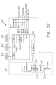
- FIG. 32 is a schematic diagram of a control circuit, in accordance with at least one aspect of the present disclosure.
- FIG. 33 shows a simplified block circuit diagram illustrating another electrical circuit contained within a modular ultrasonic surgical instrument, in accordance with at least one aspect of the present disclosure.
- FIG. 34 illustrates a generator circuit partitioned into multiple stages, in accordance with at least one aspect of the present disclosure.
- FIG. 35 illustrates a generator circuit partitioned into multiple stages where a first stage circuit is common to the second stage circuit, in accordance with at least one aspect of the present disclosure.
- FIG. 36 is a schematic diagram of one aspect of a drive circuit configured for driving a high-frequency current (RF), in accordance with at least one aspect of the present disclosure.
- RF high-frequency current
- FIG. 37 is a schematic diagram of the transformer coupled to the RF drive circuit shown in FIG. 34 , in accordance with at least one aspect of the present disclosure.
- FIG. 38 is a schematic diagram of a circuit comprising separate power sources for high power energy/drive circuits and low power circuits, according to one aspect of the resent disclosure.
- FIG. 39 illustrates a control circuit that allows a dual generator system to switch between the RF generator and the ultrasonic generator energy modalities for a surgical instrument.
- FIG. 40 illustrates a diagram of one aspect of a surgical instrument comprising a feedback system for use with a surgical instrument, according to one aspect of the present disclosure.
- FIG. 41 illustrates one aspect of a fundamental architecture for a digital synthesis circuit such as a direct digital synthesis (DDS) circuit configured to generate a plurality of wave shapes for the electrical signal waveform for use in a surgical instrument, in accordance with at least one aspect of the present disclosure.
- DDS direct digital synthesis
- FIG. 42 illustrates one aspect of direct digital synthesis (DDS) circuit configured to generate a plurality of wave shapes for the electrical signal waveform for use in surgical instrument, in accordance with at least one aspect of the present disclosure.
- DDS direct digital synthesis
- FIG. 43 illustrates one cycle of a discrete time digital electrical signal waveform, in accordance with at least one aspect of the present disclosure of an analog waveform (shown superimposed over a discrete time digital electrical signal waveform for comparison purposes), in accordance with at least one aspect of the present disclosure.
- FIG. 44 is a diagram of a control system configured to provide progressive closure of a closure member as it advances distally to close the clamp arm to apply a closure force load at a desired rate according to one aspect of this disclosure.
- FIG. 45 illustrates a proportional-integral-derivative (PID) controller feedback control system according to one aspect of this disclosure.
- PID proportional-integral-derivative
- FIG. 46 is an elevational exploded view of modular handheld ultrasonic surgical instrument showing the left shell half removed from a handle assembly exposing a device identifier communicatively coupled to the multi-lead handle terminal assembly in accordance with one aspect of the present disclosure.
- FIG. 47 is a detail view of a trigger portion and switch of the ultrasonic surgical instrument shown in FIG. 46 , in accordance with at least one aspect of the present disclosure.
- FIG. 48 is a fragmentary, enlarged perspective view of an end effector from a distal end with a jaw member in an open position, in accordance with at least one aspect of the present disclosure.
- FIG. 49 is a system diagram of a segmented circuit comprising a plurality of independently operated circuit segments, in accordance with at least one aspect of the present disclosure.
- FIG. 50 is a circuit diagram of various components of a surgical instrument with motor control functions, in accordance with at least one aspect of the present disclosure.
- FIG. 51 illustrates one aspect of an end effector comprising RF data sensors located on the jaw member, in accordance with at least one aspect of the present disclosure.
- FIG. 52 illustrates one aspect of the flexible circuit shown in FIG. 51 in which the sensors may be mounted to or formed integrally therewith, in accordance with at least one aspect of the present disclosure.
- FIG. 53 is an alternative system for controlling the frequency of an ultrasonic electromechanical system and detecting the impedance thereof, in accordance with at least one aspect of the present disclosure.
- FIG. 54 is a spectra of the same ultrasonic device with a variety of different states and conditions of the end effector where phase and magnitude of the impedance of an ultrasonic transducer are plotted as a function of frequency, in accordance with at least one aspect of the present disclosure.
- FIG. 55 is a graphical representation of a plot of a set of 3D training data S, where ultrasonic transducer impedance magnitude and phase are plotted as a function of frequency, in accordance with at least one aspect of the present disclosure.
- FIG. 56 is a logic flow diagram depicting a control program or a logic configuration to determine jaw conditions based on the complex impedance characteristic pattern (fingerprint), in accordance with at least one aspect of the present disclosure.
- FIG. 57 is a circle plot of complex impedance plotted as an imaginary component versus real components of a piezoelectric vibrator, in accordance with at least one aspect of the present disclosure.
- FIG. 58 is a circle plot of complex admittance plotted as an imaginary component versus real components of a piezoelectric vibrator, in accordance with at least one aspect of the present disclosure.
- FIG. 59 is a circle plot of complex admittance for a 55.5 kHz ultrasonic piezoelectric transducer.
- FIG. 60 is a graphical display of an impedance analyzer showing impedance/admittance circle plots for an ultrasonic device with the jaw open and no loading where red depicts admittance and blue depicts impedance, in accordance with at least one aspect of the present disclosure.
- FIG. 61 is a graphical display of an impedance analyzer showing impedance/admittance circle plots for an ultrasonic device with the jaw clamped on dry chamois where red depicts admittance and blue depicts impedance, in accordance with at least one aspect of the present disclosure.
- FIG. 62 is a graphical display of an impedance analyzer showing impedance/admittance circle plots for an ultrasonic device with the jaw tip clamped on moist chamois where red depicts admittance and blue depicts impedance, in accordance with at least one aspect of the present disclosure.
- FIG. 63 is a graphical display of an impedance analyzer showing impedance/admittance circle plots for an ultrasonic device with the jaw fully clamped on moist chamois where red depicts admittance and blue depicts impedance, in accordance with at least one aspect of the present disclosure.
- FIG. 64 is a graphical display of an impedance analyzer showing impedance/admittance plots where frequency is swept from 48 kHz to 62 kHz to capture multiple resonances of an ultrasonic device with the jaw open where the gray overlay is to help see the circles, in accordance with at least one aspect of the present disclosure.
- FIG. 65 is a logic flow diagram of a process depicting a control program or a logic configuration to determine jaw conditions based on estimates of the radius and offsets of an impedance/admittance circle, in accordance with at least one aspect of the present disclosure.
- FIGS. 66A-66B are graphical representations of an ultrasonic transducer current hemostasis algorithm, where
- FIG. 66A is a graphical representation of percent of maximum current into an ultrasonic transducer as a function of time
- FIG. 66B is a graphical representation of ultrasonic blade temperature as a function of time and tissue type, in accordance with at least one aspect of the present disclosure.
- FIG. 67 is a logic flow diagram of a process depicting a control program or a logic configuration to control the temperature of an ultrasonic blade based on tissue type, in accordance with at least one aspect of the present disclosure.
- FIG. 68 is a logic flow diagram of a process depicting a control program or a logic configuration to monitor the impedance of an ultrasonic transducer to profile an ultrasonic blade and deliver power to the ultrasonic blade on the profile according to one aspect of the resent disclosure.
- FIGS. 69A-69D is a series of graphical representations monitoring the impedance of an ultrasonic transducer to profile an ultrasonic blade and deliver power to the ultrasonic blade on the profile according to one aspect of the resent disclosure, where
- FIG. 69A is a graphical representation of the initial impedance of the ultrasonic transducer as a function of time
- FIG. 69B is a graphical representation of power delivered to the ultrasonic blade as a function of time based on the initial impedance
- FIG. 69C is a graphical representation of a new impedance of the ultrasonic transducer as a function of time
- FIG. 69D is a graphical representation of adjusted power delivered to the ultrasonic blade based on the new impedance.
- FIG. 70 is a system for adjusting complex impedance of the ultrasonic transducer to compensate for power lost when the ultrasonic blade is articulated, in accordance with at least one aspect of the present disclosure.
- FIG. 71 is a logic flow diagram of a process depicting a control program or a logic configuration to compensate output power as a function of articulation angle, in accordance with at least one aspect of the present disclosure.
- FIG. 72 is system for measuring complex impedance of an ultrasonic transducer in real time to determine action being performed by an ultrasonic blade, in accordance with at least one aspect of the present disclosure.
- FIG. 73 is a logic flow diagram of a process depicting a control program or a logic configuration to determine action being performed by the ultrasonic blade based on the complex impedance pattern, in accordance with at least one aspect of the present disclosure.
- FIG. 74 is a logic flow diagram depicting a control program or a logic configuration of an adaptive process for identifying a hemostasis vessel, in accordance with at least one aspect of the present disclosure.
- FIG. 75 is a graphical representation of ultrasonic transducer current profiles as a function of time for vein and artery vessel types, in accordance with at least one aspect of the present disclosure.
- FIG. 76 is a logic flow diagram depicting a control program or a logic configuration of an adaptive process for identifying a hemostasis vessel, in accordance with at least one aspect of the present disclosure.
- FIG. 77 is a graphical representation of ultrasonic transducer frequency profiles as a function of time for vein and artery vessel types, in accordance with at least one aspect of the present disclosure.
- FIG. 78 is a logic flow diagram depicting a control program or a logic configuration of a process for identifying a calcified vessel, in accordance with at least one aspect of the present disclosure.
- FIG. 79 is a logic flow diagram depicting a control program or a logic configuration of a process for identifying a calcified vessel, in accordance with at least one aspect of the present disclosure.
- FIG. 80 is a logic flow diagram depicting a control program or a logic configuration of a process for identifying a calcified vessel, in accordance with at least one aspect of the present disclosure.
- FIG. 81 is a diagram of a liver resection with vessels embedded in parenchymal tissue, in accordance with at least one aspect of the present disclosure.
- FIG. 82 is a diagram of an ultrasonic blade in parenchyma but not contacting a vessel, in accordance with at least one aspect of the present disclosure.
- FIGS. 83A-83B are ultrasonic transducer impedance magnitude/phase plots with curves for parenchyma shown inbold line, in accordance with at least one aspect of the present disclosure.
- FIG. 84 is a diagram of an ultrasonic blade in parenchyma and contacting a large vessel.
- FIGS. 85A-85B are ultrasonic transducer impedance magnitude/phase plots with curves for a large vessel shown inbold line, in accordance with at least one aspect of the present disclosure.
- FIG. 86 is a logic flow diagram depicting a control program or a logic configuration of a process for treating tissue in parenchyma when a vessel is detected, in accordance with at least one aspect of the present disclosure.
- FIG. 87 is an ultrasonic device configured to identify the status of the ultrasonic blade and determine the clocked clamp arm status to determine whether a disposable portion of a reusable and disposable ultrasonic device has been installed correctly, in accordance with at least one aspect of the present disclosure.
- FIG. 88 is an end effector portion of the ultrasonic device shown in FIG. 52 .
- FIG. 89 is an ultrasonic device configured to identify the status of the ultrasonic blade and determine whether the clamp arm is not completely distal to determine whether a disposable portion of a reusable and disposable ultrasonic device has been installed correctly, in accordance with at least one aspect of the present disclosure.
- FIG. 90 is a logic flow diagram depicting a control program or a logic configuration to identify the status of components of reusable and disposable devices, in accordance with at least one aspect of the present disclosure.
- FIG. 91 is a three-dimensional graphical representation of tissue radio frequency (RF) impedance classification, in accordance with at least one aspect of the present disclosure.
- FIG. 92 is a three-dimensional graphical representation of tissue radio frequency (RF) impedance analysis, in accordance with at least one aspect of the present disclosure.
- FIG. 93 is a graphical representation of carotid technique sensitivity where the time impedance (Z) derivative is plotted as a function of initial radio frequency (RF) impedance, in accordance with at least one aspect of the present disclosure.
- FIG. 94A is a graphical representation of impedance phase angle as a function of resonant frequency of the same ultrasonic device with a cold (solid line) and hot (broken line) ultrasonic blade;
- FIG. 94B is a graphical representation of impedance magnitude as a function of resonant frequency of the same ultrasonic device with a cold (solid line) and hot (broken line) ultrasonic blade.
- FIG. 95 is a diagram of a Kalman filter to improve temperature estimator and state space model based on impedance across an ultrasonic transducer measured at a variety of frequencies, in accordance with at least one aspect of the present disclosure.
- FIG. 96 are three probability distributions employed by a state estimator of the Kalman filter shown in FIG. 95 to maximize estimates, in accordance with at least one aspect of the present disclosure.
- FIG. 97A is a graphical representation of temperature versus time of an ultrasonic device with no temperature control reaching a maximum temperature of 490° C.
- FIG. 97B is a graphical representation of temperature versus time of an ultrasonic device with temperature control reaching a maximum temperature of 320° C., in accordance with at least one aspect of the present disclosure.
- FIG. 98 is a graphical representation of the relationship between initial frequency and the change in frequency required to achieve a temperature of approximately 340° C., in accordance with at least one aspect of the present disclosure.
- FIG. 99 illustrates a feedback control system comprising an ultrasonic generator to regulate the electrical current (i) set point applied to an ultrasonic transducer of an ultrasonic electromechanical system to prevent the frequency (t) of the ultrasonic transducer from decreasing lower than a predetermined threshold, in accordance with at least one aspect of the present disclosure.
- FIG. 100 is a logic flow diagram of a process depicting a control program or a logic configuration of a controlled thermal management process to protect an end effector pad, in accordance with at least one aspect of the present disclosure.
- FIG. 101 is a graphical representation of temperature versus time comparing the desired temperature of an ultrasonic blade with a smart ultrasonic blade and a conventional ultrasonic blade, in accordance with at least one aspect of the present disclosure.
- FIGS. 102A-102B are graphical representations of feedback control to adjust ultrasonic power applied to an ultrasonic transducer when a sudden drop in temperature of an ultrasonic blade is detected, where
- FIG. 102A is a graphical representation of ultrasonic power as a function of time.
- FIG. 102B is a plot of ultrasonic blade temperature as a function of time, in accordance with at least one aspect of the present disclosure.
- FIG. 103 is a logic flow diagram of a process depicting a control program or a logic configuration to control the temperature of an ultrasonic blade, in accordance with at least one aspect of the present disclosure.
- FIG. 104 is a graphical representation of ultrasonic blade temperature as a function of time during a vessel firing, in accordance with at least one aspect of the present disclosure.
- FIG. 105 is a logic flow diagram of a process depicting a control program or a logic configuration to control the temperature of an ultrasonic blade between two temperature set points, in accordance with at least one aspect of the present disclosure.
- FIG. 106 is a logic flow diagram of a process depicting a control program or a logic configuration to determine the initial temperature of an ultrasonic blade, in accordance with at least one aspect of the present disclosure.
- FIG. 107 is a logic flow diagram of a process depicting a control program or a logic configuration to determine when an ultrasonic blade is approaching instability and then adjusting the power to the ultrasonic transducer to prevent instability of the ultrasonic transducer, in accordance with at least one aspect of the present disclosure.
- FIG. 108 is a logic flow diagram of a process depicting a control program or a logic configuration to provide ultrasonic sealing with temperature control, in accordance with at least one aspect of the present disclosure.
- FIG. 109 are graphical representations of ultrasonic transducer current and ultrasonic blade temperature as a function of time, in accordance with at least one aspect of the present disclosure.
- FIG. 110 provides a diagram showing an example system with means for detecting capacitive coupling, in accordance with at least one aspect of the present disclosure.
- FIG. 111 is a logic flow diagram depicting a control program or a logic configuration of an example methodology for limiting the effects of capacitive coupling in a surgical system is disclosed, in accordance with at least one aspect of the present disclosure.
- FIG. 112 is a logic flow diagram depicting a control program or a logic configuration of an example methodology that may be performed by the surgical system utilizing monopolar energy generation to determine whether to take advantage of parasitic capacitive coupling, in accordance with at least one aspect of the present disclosure.
- FIG. 113 is a logic flow diagram depicting a control program or a logic configuration to adjust compression force applied to tissue, based on one or more selected energy modalities, according to a least one aspect of the present disclosure.
- FIG. 114 illustrates a mechanical method of adjusting compression force applied by an end effector for different treatment types, in accordance with at least one aspect of the present disclosure.
- FIGS. 115A-115B illustrate a mechanical method of adjusting compression force applied by an end effector for different treatment types, by rotating an ultrasonic blade, in accordance with at least one aspect of the present disclosure.
- FIG. 116 shows a diagram illustrating switching between active electrodes of an end effector, in accordance with at least one aspect of the present disclosure.
- FIG. 117 depicts a surgical procedure using an electrosurgical system in accordance with at least one aspect of the present disclosure.
- FIG. 118 illustrates a block diagram of the electrosurgical system used in FIG. 117 in accordance with at least one aspect of the present disclosure.
- FIG. 119 illustrates a return pad of the electrosurgical system of FIG. 117 including a plurality of electrodes in accordance with at least one aspect of the present disclosure.
- FIG. 120 illustrates an array of sensing devices in the return pad depicted in FIG. 118 in accordance with at least one aspect of the present disclosure.
- FIG. 121 is a graphical representation of a therapeutic RF signal that may be used in an electrosurgical system in accordance with at least one aspect of the present disclosure.
- FIG. 122 is a graphical representation of a nerve stimulation signal that may be incorporated in an electrosurgical system in accordance with at least one aspect of the present disclosure.
- FIGS. 123A-123C are graphical representations of signals used by an electrosurgical system that may incorporate features of both the therapeutic RF signal of FIG. 121 and the nerve stimulation signal of FIG. 122 in accordance with at least one aspect of the present disclosure.
- FIG. 124 summarizes a method in which such a control for a smart electrosurgical device may be effected in accordance with at least one aspect of the present disclosure.
- FIG. 125 illustrates an ultrasonic surgical instrument system, in accordance with at least one aspect of the present disclosure.
- FIGS. 126A-126C illustrate a piezoelectric transducer, in accordance with at least one aspect of the present disclosure.
- FIG. 127 illustrates a D31 ultrasonic transducer architecture that includes an ultrasonic waveguide and one or more piezoelectric elements fixed to the ultrasonic waveguide, in accordance with at least one aspect of the present disclosure.
- FIG. 128 illustrates a cutaway view of an ultrasonic surgical instrument, in accordance with at least one aspect of the present disclosure.
- FIG. 129 illustrates an exploded view of the ultrasonic surgical instrument in FIG. 128 , in accordance with at least one aspect of the present disclosure.
- FIG. 130 illustrates a block diagram of a surgical system, in accordance with at least one aspect of the present disclosure.
- FIG. 131 illustrates a perspective view of a surgical instrument including a sensor assembly configured to detect a user-worn magnetic reference, in accordance with at least one aspect of the present disclosure.
- FIG. 132A illustrates a sectional view along line 131 - 131 of a surgical instrument including a sensor assembly configured to detect an integral magnetic reference, in accordance with at least one aspect of the present disclosure.
- FIG. 132B illustrates a detail view of the surgical instrument of FIG. 132A in a first position, in accordance with at least one aspect of the present disclosure.
- FIG. 132C illustrates a detail view of the surgical instrument of FIG. 132A in a second position, in accordance with at least one aspect of the present disclosure.
- FIG. 133A illustrates a perspective view of a surgical instrument including a sensor assembly configured to detect contact thereagainst that is oriented orthogonally, in accordance with at least one aspect of the present disclosure.
- FIG. 133B illustrates a perspective view of a surgical instrument including a sensor assembly configured to detect contact thereagainst that is oriented laterally, in accordance with at least one aspect of the present disclosure.
- FIG. 134 illustrates a circuit diagram of the surgical instrument of either FIG. 133A or FIG. 133B , in accordance with at least one aspect of the present disclosure.
- FIG. 135A illustrates a perspective view of a surgical instrument including a sensor assembly configured to detect closure of the surgical instrument, wherein the surgical instrument is in an open position, in accordance with at least one aspect of the present disclosure.
- FIG. 135B illustrates a perspective view of a surgical instrument including a sensor assembly configured to detect closure of the surgical instrument, wherein the surgical instrument is in a first closed position, in accordance with at least one aspect of the present disclosure.
- FIG. 135C illustrates a perspective view of a surgical instrument including a sensor assembly configured to detect closure of the surgical instrument, wherein the surgical instrument is in a second closed position, in accordance with at least one aspect of the present disclosure.
- FIG. 136A illustrates a perspective view of a surgical instrument including a sensor assembly configured to detect opening of the surgical instrument, in accordance with at least one aspect of the present disclosure.
- FIG. 136B illustrates a sectional view along line 135 B- 135 B of the surgical instrument of FIG. 136A , in accordance with at least one aspect of the present disclosure.
- FIG. 136C illustrates an exploded perspective view of the surgical instrument of FIG. 136A , in accordance with at least one aspect of the present disclosure.
- FIG. 136D illustrates a perspective view of the surgical instrument of FIG. 136A , in accordance with at least one aspect of the present disclosure.
- FIG. 136E illustrates a detail view of a portion of FIG. 136D , in accordance with at least one aspect of the present disclosure.
- FIG. 136F illustrates a perspective view of the interior face of the arm of the surgical instrument of FIG. 136A , in accordance with at least one aspect of the present disclosure.
- FIG. 137 illustrates a perspective view of a surgical instrument including a sensor assembly comprising a pair of sensors for controlling the activation of the surgical instrument, in accordance with at least one aspect of the present disclosure.
- FIG. 138 illustrates a perspective view of a surgical instrument comprising a deactivation switch, in accordance with at least one aspect of the present disclosure.
- FIG. 139 illustrates a perspective view of a retractor comprising a sensor, in accordance with at least one aspect of the present disclosure.
- FIG. 140 illustrates a perspective view of a retractor comprising a display in use at a surgical site, in accordance with at least one aspect of the present disclosure.
- FIG. 141 is a timeline depicting situational awareness of a surgical hub, in accordance with at least one aspect of the present disclosure.
- aspects of the ultrasonic surgical devices can be configured for transecting and/or coagulating tissue during surgical procedures, for example.
- aspects of the electrosurgical devices can be configured for transecting, coagulating, scaling, welding and/or desiccating tissue during surgical procedures, for example.
- a computer-implemented interactive surgical system 100 includes one or more surgical systems 102 and a cloud-based system (e.g., the cloud 104 that may include a remote server 113 coupled to a storage device 105 ).
- Each surgical system 102 includes at least one surgical hub 106 in communication with the cloud 104 that may include a remote server 113 .
- the surgical system 102 includes a visualization system 108 , a robotic system 110 , and a handheld intelligent surgical instrument 112 , which are configured to communicate with one another and/or the hub 106 .
- a surgical system 102 may include an M number of hubs 106 , an N number of visualization systems 108 , an O number of robotic systems 110 , and a P number of handheld intelligent surgical instruments 112 , where M, N, O, and P are integers greater than or equal to one.
- FIG. 3 depicts an example of a surgical system 102 being used to perform a surgical procedure on a patient who is lying down on an operating table 114 in a surgical operating room 116 .
- a robotic system 110 is used in the surgical procedure as a part of the surgical system 102 .
- the robotic system 110 includes a surgeon's console 118 , a patient side cart 120 (surgical robot), and a surgical robotic hub 122 .
- the patient side cart 120 can manipulate at least one removably coupled surgical tool 117 through a minimally invasive incision in the body of the patient while the surgeon views the surgical site through the surgeon's console 118 .
- An image of the surgical site can be obtained by a medical imaging device 124 , which can be manipulated by the patient side cart 120 to orient the imaging device 124 .
- the robotic hub 122 can be used to process the images of the surgical site for subsequent display to the surgeon through the surgeon's console 118 .
- the imaging device 124 includes at least one image sensor and one or more optical components.
- Suitable image sensors include, but are not limited to, Charge-Coupled Device (CCD) sensors and Complementary Metal-Oxide Semiconductor (CMOS) sensors.
- CCD Charge-Coupled Device
- CMOS Complementary Metal-Oxide Semiconductor
- the optical components of the imaging device 124 may include one or more illumination sources and/or one or more lenses.
- the one or more illumination sources may be directed to illuminate portions of the surgical field.
- the one or more image sensors may receive light reflected or refracted from the surgical field, including light reflected or refracted from tissue and/or surgical instruments.
- the one or more illumination sources may be configured to radiate electromagnetic energy in the visible spectrum as well as the invisible spectrum.
- the visible spectrum sometimes referred to as the optical spectrum or luminous spectrum, is that portion of the electromagnetic spectrum that is visible to (i.e., can be detected by) the human eye and may be referred to as visible light or simply light.
- a typical human eye will respond to wavelengths in air that are from about 380 nm to about 750 nm.
- the invisible spectrum is that portion of the electromagnetic spectrum that lies below and above the visible spectrum (i.e., wavelengths below about 380 nm and above about 750 nm).
- the invisible spectrum is not detectable by the human eye.
- Wavelengths greater than about 750 nm are longer than the red visible spectrum, and they become invisible infrared (IR), microwave, and radio electromagnetic radiation.
- Wavelengths less than about 380 nm are shorter than the violet spectrum, and they become invisible ultraviolet, x-ray, and gamma ray electromagnetic radiation.
- the imaging device 124 is configured for use in a minimally invasive procedure.
- imaging devices suitable for use with the present disclosure include, but not limited to, an arthroscope, angioscope, bronchoscope, choledochoscope, colonoscope, cytoscope, duodenoscope, enteroscope, esophagogastro-duodenoscope (gastroscope), endoscope, laryngoscope, nasopharyngo-neproscope, sigmoidoscope, thoracoscope, and ureteroscope.
- the imaging device employs multi-spectrum monitoring to discriminate topography and underlying structures.
- a multi-spectral image is one that captures image data within specific wavelength ranges across the electromagnetic spectrum. The wavelengths may be separated by filters or by the use of instruments that are sensitive to particular wavelengths, including light from frequencies beyond the visible light range, e.g., IR and ultraviolet. Spectral imaging can allow extraction of additional information the human eye fails to capture with its receptors for red, green, and blue.
- Multi-spectrum monitoring can be a useful tool in relocating a surgical field after a surgical task is completed to perform one or more of the previously described tests on the treated tissue.
- the sterile field may be considered a specified area, such as within a tray or on a sterile towel, that is considered free of microorganisms, or the sterile field may be considered an area, immediately around a patient, who has been prepared for a surgical procedure.
- the sterile field may include the scrubbed team members, who are properly attired, and all furniture and fixtures in the area.
- the visualization system 108 includes one or more imaging sensors, one or more image-processing units, one or more storage arrays, and one or more displays that are strategically arranged with respect to the sterile field, as illustrated in FIG. 2 .
- the visualization system 108 includes an interface for HL7, PACS, and EMR.
- Various components of the visualization system 108 are described under the heading “Advanced Imaging Acquisition Module” in U.S. Provisional Patent Application Ser. No. 62/611,341, titled INTERACTIVE SURGICAL PLATFORM, filed Dec. 28, 2017, the disclosure of which is herein incorporated by reference in its entirety.
- a primary display 119 is positioned in the sterile field to be visible to an operator at the operating table 114 .
- a visualization tower 111 is positioned outside the sterile field.
- the visualization tower 111 includes a first non-sterile display 107 and a second non-sterile display 109 , which face away from each other.
- the visualization system 108 guided by the hub 106 , is configured to utilize the displays 107 , 109 , and 119 to coordinate information flow to operators inside and outside the sterile field.
- the hub 106 may cause the visualization system 108 to display a snapshot of a surgical site, as recorded by an imaging device 124 , on a non-sterile display 107 or 109 , while maintaining a live feed of the surgical site on the primary display 119 .
- the snapshot on the non-sterile display 107 or 109 can permit a non-sterile operator to perform a diagnostic step relevant to the surgical procedure, for example.
- the hub 106 is also configured to route a diagnostic input or feedback entered by a non-sterile operator at the visualization tower 111 to the primary display 119 within the sterile field, where it can be viewed by a sterile operator at the operating table.
- the input can be in the form of a modification to the snapshot displayed on the non-sterile display 107 or 109 , which can be routed to the primary display 119 by the hub 106 .
- a surgical instrument 112 is being used in the surgical procedure as part of the surgical system 102 .
- the hub 106 is also configured to coordinate information flow to a display of the surgical instrument 112 .
- a diagnostic input or feedback entered by a non-sterile operator at the visualization tower 111 can be routed by the hub 106 to the surgical instrument display 115 within the sterile field, where it can be viewed by the operator of the surgical instrument 112 .
- Example surgical instruments that are suitable for use with the surgical system 102 are described under the heading “Surgical Instrument Hardware” and in U.S. Provisional Patent Application Ser. No. 62/611,341, titled INTERACTIVE SURGICAL PLATFORM, filed Dec. 28, 2017, the disclosure of which is herein incorporated by reference in its entirety, for example.
- a hub 106 is depicted in communication with a visualization system 108 , a robotic system 110 , and a handheld intelligent surgical instrument 112 .
- the hub 106 includes a hub display 135 , an imaging module 138 , a generator module 140 , a communication module 130 , a processor module 132 , and a storage array 134 .
- the hub 106 further includes a smoke evacuation module 126 and/or a suction/irrigation module 128 .
- the hub modular enclosure 136 offers a unified environment for managing the power, data, and fluid lines, which reduces the frequency of entanglement between such lines.
- the surgical hub for use in a surgical procedure that involves energy application to tissue at a surgical site.
- the surgical hub includes a hub enclosure and a combo generator module slidably receivable in a docking station of the hub enclosure.
- the docking station includes data and power contacts.
- the combo generator module includes two or more of an ultrasonic energy generator component, a bipolar RF energy generator component, and a monopolar RF energy generator component that are housed in a single unit.
- the combo generator module also includes a smoke evacuation component, at least one energy delivery cable for connecting the combo generator module to a surgical instrument, at least one smoke evacuation component configured to evacuate smoke, fluid, and/or particulates generated by the application of therapeutic energy to the tissue, and a fluid line extending from the remote surgical site to the smoke evacuation component.
- the fluid line is a first fluid line and a second fluid line extends from the remote surgical site to a suction and irrigation module slidably received in the hub enclosure.
- the hub enclosure comprises a fluid interface.
- Certain surgical procedures may require the application of more than one energy type to the tissue.
- One energy type may be more beneficial for cutting the tissue, while another different energy type may be more beneficial for sealing the tissue.
- a bipolar generator can be used to seal the tissue while an ultrasonic generator can be used to cut the sealed tissue.
- the modular surgical enclosure includes a first energy-generator module, configured to generate a first energy for application to the tissue, and a first docking station comprising a first docking port that includes first data and power contacts, wherein the first energy-generator module is slidably movable into an electrical engagement with the power and data contacts and wherein the first energy-generator module is slidably movable out of the electrical engagement with the first power and data contacts,
- the modular surgical enclosure also includes a second energy-generator module configured to generate a second energy, different than the first energy, for application to the tissue, and a second docking station comprising a second docking port that includes second data and power contacts, wherein the second energy-generator module is slidably movable into an electrical engagement with the power and data contacts, and wherein the second energy-generator module is slidably movable out of the electrical engagement with the second power and data contacts.
- a second energy-generator module configured to generate a second energy, different than the first energy, for application to the tissue
- a second docking station comprising a second docking port that includes second data and power contacts
- the modular surgical enclosure also includes a communication bus between the first docking port and the second docking port, configured to facilitate communication between the first energy-generator module and the second energy-generator module.
- a hub modular enclosure 136 that allows the modular integration of a generator module 140 , a smoke evacuation module 126 , and a suction/irrigation module 128 .
- the hub modular enclosure 136 further facilitates interactive communication between the modules 140 , 126 , 128 .
- the generator module 140 can be a generator module with integrated monopolar, bipolar, and ultrasonic components supported in a single housing unit 139 slidably insertable into the hub modular enclosure 136 .
- the generator module 140 can be configured to connect to a monopolar device 146 , a bipolar device 147 , and an ultrasonic device 148 .
- the generator module 140 may comprise a series of monopolar, bipolar, and/or ultrasonic generator modules that interact through the hub modular enclosure 136 .
- the hub modular enclosure 136 can be configured to facilitate the insertion of multiple generators and interactive communication between the generators docked into the hub modular enclosure 136 so that the generators would act as a single generator.
- the hub modular enclosure 136 comprises a modular power and communication backplane 149 with external and wireless communication headers to enable the removable attachment of the modules 140 , 126 , 128 and interactive communication therebetween.
- the hub modular enclosure 136 includes docking stations, or drawers, 151 , herein also referred to as drawers, which are configured to slidably receive the modules 140 , 126 , 128 .
- FIG. 4 illustrates a partial perspective view of a surgical hub enclosure 136 , and a combo generator module 145 slidably receivable in a docking station 151 of the surgical hub enclosure 136 .
- a docking port 152 with power and data contacts on a rear side of the combo generator module 145 is configured to engage a corresponding docking port 150 with power and data contacts of a corresponding docking station 151 of the hub modular enclosure 136 as the combo generator module 145 is slid into position within the corresponding docking station 151 of the hub module enclosure 136 .
- the combo generator module 145 includes a bipolar, ultrasonic, and monopolar module and a smoke evacuation module integrated together into a single housing unit 139 , as illustrated in FIG. 5 .
- the smoke evacuation module 126 includes a fluid line 154 that conveys captured/collected smoke and/or fluid away from a surgical site and to, for example, the smoke evacuation module 126 .
- Vacuum suction originating from the smoke evacuation module 126 can draw the smoke into an opening of a utility conduit at the surgical site.
- the utility conduit, coupled to the fluid line, can be in the form of a flexible tube terminating at the smoke evacuation module 126 .
- the utility conduit and the fluid line define a fluid path extending toward the smoke evacuation module 126 that is received in the hub enclosure 136 .
- the suction/irrigation module 128 is coupled to a surgical tool comprising an aspiration fluid line and a suction fluid line.
- the aspiration and suction fluid lines are in the form of flexible tubes extending from the surgical site toward the suction/irrigation module 128 .
- One or more drive systems can be configured to cause irrigation and aspiration of fluids to and from the surgical site.
- the surgical tool includes a shaft having an end effector at a distal end thereof and at least one energy treatment associated with the end effector, an aspiration tube, and an irrigation tube.
- the aspiration tube can have an inlet port at a distal end thereof and the aspiration tube extends through the shaft.
- an irrigation tube can extend through the shaft and can have an inlet port in proximity to the energy deliver implement.
- the energy deliver implement is configured to deliver ultrasonic and/or RF energy to the surgical site and is coupled to the generator module 140 by a cable extending initially through the shaft.
- the irrigation tube can be in fluid communication with a fluid source, and the aspiration tube can be in fluid communication with a vacuum source.
- the fluid source and/or the vacuum source can be housed in the suction/irrigation module 128 .
- the fluid source and/or the vacuum source can be housed in the hub enclosure 136 separately from the suction/irrigation module 128 .
- a fluid interface can be configured to connect the suction/irrigation module 128 to the fluid source and/or the vacuum source.
- the modules 140 , 126 , 128 and/or their corresponding docking stations on the hub modular enclosure 136 may include alignment features that are configured to align the docking ports of the modules into engagement with their counterparts in the docking stations of the hub modular enclosure 136 .
- the combo generator module 145 includes side brackets 155 that are configured to slidably engage with corresponding brackets 156 of the corresponding docking station 151 of the hub modular enclosure 136 . The brackets cooperate to guide the docking port contacts of the combo generator module 145 into an electrical engagement with the docking port contacts of the hub modular enclosure 136 .
- the drawers 151 of the hub modular enclosure 136 are the same, or substantially the same size, and the modules are adjusted in size to be received in the drawers 151 .
- the side brackets 155 and/or 156 can be larger or smaller depending on the size of the module.
- the drawers 151 are different in size and are each designed to accommodate a particular module.
- the contacts of a particular module can be keyed for engagement with the contacts of a particular drawer to avoid inserting a module into a drawer with mismatching contacts.
- the docking port 150 of one drawer 151 can be coupled to the docking port 150 of another drawer 151 through a communications link 157 to facilitate an interactive communication between the modules housed in the hub modular enclosure 136 .
- the docking ports 150 of the hub modular enclosure 136 may alternatively, or additionally, facilitate a wireless interactive communication between the modules housed in the hub modular enclosure 136 .
- Any suitable wireless communication can be employed, such as for example Air Titan-Bluetooth.
- FIG. 6 illustrates individual power bus attachments for a plurality of lateral docking ports of a lateral modular housing 160 configured to receive a plurality of modules of a surgical hub 206 .
- the lateral modular housing 160 is configured to laterally receive and interconnect the modules 161 .
- the modules 161 are slidably inserted into docking stations 162 of lateral modular housing 160 , which includes a backplane for interconnecting the modules 161 .
- the modules 161 are arranged laterally in the lateral modular housing 160 .
- the modules 161 may be arranged vertically in a lateral modular housing.
- FIG. 7 illustrates a vertical modular housing 164 configured to receive a plurality of modules 165 of the surgical hub 106 .
- the modules 165 are slidably inserted into docking stations, or drawers, 167 of vertical modular housing 164 , which includes a backplane for interconnecting the modules 165 .
- the drawers 167 of the vertical modular housing 164 are arranged vertically, in certain instances, a vertical modular housing 164 may include drawers that are arranged laterally.
- the modules 165 may interact with one another through the docking ports of the vertical modular housing 164 .
- a display 177 is provided for displaying data relevant to the operation of the modules 165 .
- the vertical modular housing 164 includes a master module 178 housing a plurality of sub-modules that are slidably received in the master module 178 .
- the imaging module 138 comprises an integrated video processor and a modular light source and is adapted for use with various imaging devices.
- the imaging device is comprised of a modular housing that can be assembled with a light source module and a camera module.
- the housing can be a disposable housing.
- the disposable housing is removably coupled to a reusable controller, a light source module, and a camera module.
- the light source module and/or the camera module can be selectively chosen depending on the type of surgical procedure.
- the camera module comprises a CCD sensor.
- the camera module comprises a CMOS sensor.
- the camera module is configured for scanned beam imaging.
- the light source module can be configured to deliver a white light or a different light, depending on the surgical procedure.
- the module imaging device of the present disclosure is configured to permit the replacement of a light source module or a camera module midstream during a surgical procedure, without having to remove the imaging device from the surgical field.
- the imaging device comprises a tubular housing that includes a plurality of channels.
- a first channel is configured to slidably receive the camera module, which can be configured for a snap-fit engagement with the first channel.
- a second channel is configured to slidably receive the light source module, which can be configured for a snap-fit engagement with the second channel.
- the camera module and/or the light source module can be rotated into a final position within their respective channels.
- a threaded engagement can be employed in lieu of the snap-fit engagement.
- multiple imaging devices are placed at different positions in the surgical field to provide multiple views.
- the imaging module 138 can be configured to switch between the imaging devices to provide an optimal view.
- the imaging module 138 can be configured to integrate the images from the different imaging device.
- FIG. 8 illustrates a surgical data network 201 comprising a modular communication hub 203 configured to connect modular devices located in one or more operating theaters of a healthcare facility, or any room in a healthcare facility specially equipped for surgical operations, to a cloud-based system (e.g., the cloud 204 that may include a remote server 213 coupled to a storage device 205 ).
- the modular communication hub 203 comprises a network hub 207 and/or a network switch 209 in communication with a network router.
- the modular communication hub 203 also can be coupled to a local computer system 210 to provide local computer processing and data manipulation.
- the surgical data network 201 may be configured as passive, intelligent, or switching.
- a passive surgical data network serves as a conduit for the data, enabling it to go from one device (or segment) to another and to the cloud computing resources.
- An intelligent surgical data network includes additional features to enable the traffic passing through the surgical data network to be monitored and to configure each port in the network hub 207 or network switch 209 .
- An intelligent surgical data network may be referred to as a manageable hub or switch.
- a switching hub reads the destination address of each packet and then forwards the packet to the correct port.
- Modular devices 1 a - 1 n located in the operating theater may be coupled to the modular communication hub 203 .
- the network hub 207 and/or the network switch 209 may be coupled to a network router 211 to connect the devices 1 a - 1 n to the cloud 204 or the local computer system 210 .
- Data associated with the devices 1 a - 1 n may be transferred to cloud-based computers via the router for remote data processing and manipulation.
- Data associated with the devices 1 a - 1 n may also be transferred to the local computer system 210 for local data processing and manipulation.
- Modular devices 2 a - 2 m located in the same operating theater also may be coupled to a network switch 209 .
- the network switch 209 may be coupled to the network hub 207 and/or the network router 211 to connect to the devices 2 a - 2 m to the cloud 204 .
- Data associated with the devices 2 a - 2 n may be transferred to the cloud 204 via the network router 211 for data processing and manipulation.
- Data associated with the devices 2 a - 2 m may also be transferred to the local computer system 210 for local data processing and manipulation.
- the surgical data network 201 may be expanded by interconnecting multiple network hubs 207 and/or multiple network switches 209 with multiple network routers 211 .
- the modular communication hub 203 may be contained in a modular control tower configured to receive multiple devices 1 a - 1 n / 2 a - 2 m .
- the local computer system 210 also may be contained in a modular control tower.
- the modular communication hub 203 is connected to a display 212 to display images obtained by some of the devices 1 a - 1 n / 2 a - 2 m , for example during surgical procedures.
- the devices 1 a - 1 n / 2 a - 2 m may include, for example, various modules such as an imaging module 138 coupled to an endoscope, a generator module 140 coupled to an energy-based surgical device, a smoke evacuation module 126 , a suction/irrigation module 128 , a communication module 130 , a processor module 132 , a storage array 134 , a surgical device coupled to a display, and/or a non-contact sensor module, among other modular devices that may be connected to the modular communication hub 203 of the surgical data network 201 .
- various modules such as an imaging module 138 coupled to an endoscope, a generator module 140 coupled to an energy-based surgical device, a smoke evacuation module 126 , a suction/irrigation module 128 , a communication module 130 , a processor module 132 , a storage array 134 , a surgical device coupled to a display, and/or a non-contact sensor module, among other modular devices that may be connected to the
- the surgical data network 201 may comprise a combination of network hub(s), network switch(es), and network router(s) connecting the devices 1 a - 1 n / 2 a - 2 m to the cloud. Any one of or all of the devices 1 a - 1 n / 2 a - 2 m coupled to the network hub or network switch may collect data in real time and transfer the data to cloud computers for data processing and manipulation. It will be appreciated that cloud computing relies on sharing computing resources rather than having local servers or personal devices to handle software applications.
- the word “cloud” may be used as a metaphor for “the Internet,” although the term is not limited as such.
- cloud computing may be used herein to refer to “a type of Internet-based computing,” where different services—such as servers, storage, and applications—are delivered to the modular communication hub 203 and/or computer system 210 located in the surgical theater (e.g., a fixed, mobile, temporary, or field operating room or space) and to devices connected to the modular communication hub 203 and/or computer system 210 through the Internet.
- the cloud infrastructure may be maintained by a cloud service provider.
- the cloud service provider may be the entity that coordinates the usage and control of the devices 1 a - 1 n / 2 a - 2 m located in one or more operating theaters.
- the cloud computing services can perform a large number of calculations based on the data gathered by smart surgical instruments, robots, and other computerized devices located in the operating theater.
- the hub hardware enables multiple devices or connections to be connected to a computer that communicates with the cloud computing resources and storage.
- the surgical data network provides improved surgical outcomes, reduced costs, and improved patient satisfaction.
- At least some of the devices 1 a - 1 n / 2 a - 2 m may be employed to view tissue states to assess leaks or perfusion of sealed tissue after a tissue sealing and cutting procedure.
- At least some of the devices 1 a - 1 n / 2 a - 2 m may be employed to identify pathology, such as the effects of diseases, using the cloud-based computing to examine data including images of samples of body tissue for diagnostic purposes. This includes localization and margin confirmation of tissue and phenotypes.
- At least some of the devices 1 a - 1 n / 2 a - 2 m may be employed to identify anatomical structures of the body using a variety of sensors integrated with imaging devices and techniques such as overlaying images captured by multiple imaging devices.
- the data gathered by the devices 1 a - 1 n / 2 a - 2 m may be transferred to the cloud 204 or the local computer system 210 or both for data processing and manipulation including image processing and manipulation.
- the data may be analyzed to improve surgical procedure outcomes by determining if further treatment, such as the application of endoscopic intervention, emerging technologies, a targeted radiation, targeted intervention, and precise robotics to tissue-specific sites and conditions, may be pursued.
- Such data analysis may further employ outcome analytics processing, and using standardized approaches may provide beneficial feedback to either confirm surgical treatments and the behavior of the surgeon or suggest modifications to surgical treatments and the behavior of the surgeon.
- the operating theater devices 1 a - 1 n may be connected to the modular communication hub 203 over a wired channel or a wireless channel depending on the configuration of the devices 1 a - 1 n to a network hub.
- the network hub 207 may be implemented, in one aspect, as a local network broadcast device that works on the physical layer of the Open System Interconnection (OSI) model.
- the network hub provides connectivity to the devices 1 a - 1 n located in the same operating theater network.
- the network hub 207 collects data in the form of packets and sends them to the router in half duplex mode.
- the network hub 207 does not store any media access control/Internet Protocol (MAC/IP) to transfer the device data.
- MAC/IP media access control/Internet Protocol
- the network hub 207 has no routing tables or intelligence regarding where to send information and broadcasts all network data across each connection and to a remote server 213 ( FIG. 9 ) over the cloud 204 .
- the network hub 207 can detect basic network errors such as collisions, but having all information broadcast to multiple ports can be a security risk and cause bottlenecks.
- the operating theater devices 2 a - 2 m may be connected to a network switch 209 over a wired channel or a wireless channel.
- the network switch 209 works in the data link layer of the OSI model.
- the network switch 209 is a multicast device for connecting the devices 2 a - 2 m located in the same operating theater to the network.
- the network switch 209 sends data in the form of frames to the network router 211 and works in full duplex mode. Multiple devices 2 a - 2 m can send data at the same time through the network switch 209 .
- the network switch 209 stores and uses MAC addresses of the devices 2 a - 2 m to transfer data.
- the network hub 207 and/or the network switch 209 are coupled to the network router 211 for connection to the cloud 204 .
- the network router 211 works in the network layer of the OSI model.
- the network router 211 creates a route for transmitting data packets received from the network hub 207 and/or network switch 211 to cloud-based computer resources for further processing and manipulation of the data collected by any one of or all the devices 1 a - 1 n / 2 a - 2 m .
- the network router 211 may be employed to connect two or more different networks located in different locations, such as, for example, different operating theaters of the same healthcare facility or different networks located in different operating theaters of different healthcare facilities.
- the network router 211 sends data in the form of packets to the cloud 204 and works in full duplex mode. Multiple devices can send data at the same time.
- the network router 211 uses IP addresses to transfer data.
- the network hub 207 may be implemented as a USB hub, which allows multiple USB devices to be connected to a host computer.
- the USB hub may expand a single USB port into several tiers so that there are more ports available to connect devices to the host system computer.
- the network hub 207 may include wired or wireless capabilities to receive information over a wired channel or a wireless channel.
- a wireless USB short-range, high-bandwidth wireless radio communication protocol may be employed for communication between the devices 1 a - 1 n and devices 2 a - 2 m located in the operating theater.
- the operating theater devices 1 a - 1 n / 2 a - 2 m may communicate to the modular communication hub 203 via Bluetooth wireless technology standard for exchanging data over short distances (using short-wavelength UHF radio waves in the ISM band from 2.4 to 2.485 GHz) from fixed and mobile devices and building personal area networks (PANs).
- PANs personal area networks
- the operating theater devices 1 a - 1 n / 2 a - 2 m may communicate to the modular communication hub 203 via a number of wireless or wired communication standards or protocols, including but not limited to Wi-Fi (IEEE 802.11 family), WiMAX (IEEE 802.16 family), IEEE 802.20, long-term evolution (LTE), and Ev-DO, HSPA+, HSDPA+, HSUPA+, EDGE, GSM, GPRS, CDMA, TDMA, DECT, and Ethernet derivatives thereof, as well as any other wireless and wired protocols that are designated as 3G, 4G, 5G, and beyond.
- the computing module may include a plurality of communication modules.
- a first communication module may be dedicated to shorter-range wireless communications such as Wi-Fi and Bluetooth, and a second communication module may be dedicated to longer-range wireless communications such as GPS, EDGE, GPRS, CDMA, WiMAX, LTE, Ev-DO, and others.
- the modular communication hub 203 may serve as a central connection for one or all of the operating theater devices 1 a - 1 n / 2 a - 2 m and handles a data type known as frames. Frames carry the data generated by the devices 1 a - 1 n / 2 a - 2 m . When a frame is received by the modular communication hub 203 , it is amplified and transmitted to the network router 211 , which transfers the data to the cloud computing resources by using a number of wireless or wired communication standards or protocols, as described herein.
- the modular communication hub 203 can be used as a standalone device or be connected to compatible network hubs and network switches to form a larger network.
- the modular communication hub 203 is generally easy to install, configure, and maintain, making it a good option for networking the operating theater devices 1 a - 1 n / 2 a - 2 m.
- FIG. 9 illustrates a computer-implemented interactive surgical system 200 .
- the computer-implemented interactive surgical system 200 is similar in many respects to the computer-implemented interactive surgical system 100 .
- the computer-implemented interactive surgical system 200 includes one or more surgical systems 202 , which are similar in many respects to the surgical systems 102 .
- Each surgical system 202 includes at least one surgical hub 206 in communication with a cloud 204 that may include a remote server 213 .
- the computer-implemented interactive surgical system 200 comprises a modular control tower 236 connected to multiple operating theater devices such as, for example, intelligent surgical instruments, robots, and other computerized devices located in the operating theater. As shown in FIG.
- the modular control tower 236 comprises a modular communication hub 203 coupled to a computer system 210 .
- the modular control tower 236 is coupled to an imaging module 238 that is coupled to an endoscope 239 , a generator module 240 that is coupled to an energy device 241 , a smoke evacuator module 226 , a suction/irrigation module 228 , a communication module 230 , a processor module 232 , a storage array 234 , a smart device/instrument 235 optionally coupled to a display 237 , and a non-contact sensor module 242 .
- the operating theater devices are coupled to cloud computing resources and data storage via the modular control tower 236 .
- a robot hub 222 also may be connected to the modular control tower 236 and to the cloud computing resources.
- the devices/instruments 235 , visualization systems 208 may be coupled to the modular control tower 236 via wired or wireless communication standards or protocols, as described herein.
- the modular control tower 236 may be coupled to a hub display 215 (e.g., monitor, screen) to display and overlay images received from the imaging module, device/instrument display, and/or other visualization systems 208 .
- the hub display also may display data received from devices connected to the modular control tower in conjunction with images and overlaid images.
- FIG. 10 illustrates a surgical hub 206 comprising a plurality of modules coupled to the modular control tower 236 .
- the modular control tower 236 comprises a modular communication hub 203 , e.g., a network connectivity device, and a computer system 210 to provide local processing, visualization, and imaging, for example.
- the modular communication hub 203 may be connected in a tiered configuration to expand the number of modules (e.g., devices) that may be connected to the modular communication hub 203 and transfer data associated with the modules to the computer system 210 , cloud computing resources, or both.
- each of the network hubs/switches in the modular communication hub 203 includes three downstream ports and one upstream port.
- the upstream network hub/switch is connected to a processor to provide a communication connection to the cloud computing resources and a local display 217 . Communication to the cloud 204 may be made either through a wired or a wireless communication channel.
- the surgical hub 206 employs a non-contact sensor module 242 to measure the dimensions of the operating theater and generate a map of the surgical theater using either ultrasonic or laser-type non-contact measurement devices.
- An ultrasound-based non-contact sensor module scans the operating theater by transmitting a burst of ultrasound and receiving the echo when it bounces off the perimeter walls of an operating theater as described under the heading “Surgical Hub Spatial Awareness Within an Operating Room” in U.S. Provisional Patent Application Ser. No. 62/611,341, titled INTERACTIVE SURGICAL PLATFORM, filed Dec. 28, 2017, which is herein incorporated by reference in its entirety, in which the sensor module is configured to determine the size of the operating theater and to adjust Bluetooth-pairing distance limits.
- a laser-based non-contact sensor module scans the operating theater by transmitting laser light pulses, receiving laser light pulses that bounce off the perimeter walls of the operating theater, and comparing the phase of the transmitted pulse to the received pulse to determine the size of the operating theater and to adjust Bluetooth pairing distance limits, for example.
- the computer system 210 comprises a processor 244 and a network interface 245 .
- the processor 244 is coupled to a communication module 247 , storage 248 , memory 249 , non-volatile memory 250 , and input/output interface 251 via a system bus.
- the system bus can be any of several types of bus structure(s) including the memory bus or memory controller, a peripheral bus or external bus, and/or a local bus using any variety of available bus architectures including, but not limited to, 9-bit bus, Industrial Standard Architecture (ISA), Micro-Charmel Architecture (MSA), Extended ISA (EISA), Intelligent Drive Electronics (IDE), VESA Local Bus (VLB), Peripheral Component Interconnect (PCI), USB, Advanced Graphics Port (AGP), Personal Computer Memory Card International Association bus (PCMCIA), Small Computer Systems Interface (SCSI), or any other proprietary bus.
- ISA Industrial Standard Architecture
- MSA Micro-Charmel Architecture
- EISA Extended ISA
- IDE Intelligent Drive Electronics
- VLB VESA Local Bus
- PCI Peripheral Component Interconnect
- USB Universal Serial Bus
- AGP Advanced Graphics Port
- PCMCIA Personal Computer Memory Card International Association bus
- SCSI Small Computer Systems Interface
- the processor 244 may be any single-core or multicore processor such as those known under the trade name ARM Cortex by Texas Instruments.
- the processor may be an LM4F230H5QR ARM Cortex-M4F Processor Core, available from Texas Instruments, for example, comprising an on-chip memory of 256 KB single-cycle flash memory, or other non-volatile memory, up to 40 MHz, a prefetch buffer to improve performance above 40 MHz, a 32 KB single-cycle serial random access memory (SRAM), an internal read-only memory (ROM) loaded with StellarisWare® software, a 2 KB electrically erasable programmable read-only memory (EEPROM), and/or one or more pulse width modulation (PWM) modules, one or more quadrature encoder inputs (QEI) analogs, one or more 12-bit analog-to-digital converters (ADCs) with 12 analog input channels, details of which are available for the product datasheet.
- QEI quadrature encoder inputs
- the processor 244 may comprise a safety controller comprising two controller-based families such as TMS570 and RM4x, known under the trade name Hercules ARM Cortex R4, also by Texas Instruments.
- the safety controller may be configured specifically for IEC 61508 and ISO 26262 safety critical applications, among others, to provide advanced integrated safety features while delivering scalable performance, connectivity, and memory options.
- the system memory includes volatile memory and non-volatile memory.
- the basic input/output system (BIOS) containing the basic routines to transfer information between elements within the computer system, such as during start-up, is stored in non-volatile memory.
- the non-volatile memory can include ROM, programmable ROM (PROM), electrically programmable ROM (EPROM), EEPROM, or flash memory.
- Volatile memory includes random-access memory (RAM), which acts as external cache memory.
- RAM is available in many forms such as SRAM, dynamic RAM (DRAM), synchronous DRAM (SDRAM), double data rate SDRAM (DDR SDRAM), enhanced SDRAM (ESDRAM), Synchlink DRAM (SLDRAM), and direct Rambus RAM (DRRAM).
- the computer system 210 also includes removable/non-removable, volatile/non-volatile computer storage media, such as for example disk storage.
- the disk storage includes, but is not limited to, devices like a magnetic disk drive, floppy disk drive, tape drive, Jaz drive, Zip drive, LS-60 drive, flash memory card, or memory stick.
- the disk storage can include storage media separately or in combination with other storage media including, but not limited to, an optical disc drive such as a compact disc ROM device (CD-ROM), compact disc recordable drive (CD-R Drive), compact disc rewritable drive (CD-RW Drive), or a digital versatile disc ROM drive (DVD-ROM).
- CD-ROM compact disc ROM
- CD-R Drive compact disc recordable drive
- CD-RW Drive compact disc rewritable drive
- DVD-ROM digital versatile disc ROM drive
- a removable or non-removable interface may be employed.
- the computer system 210 includes software that acts as an intermediary between users and the basic computer resources described in a suitable operating environment.
- Such software includes an operating system.
- the operating system which can be stored on the disk storage, acts to control and allocate resources of the computer system.
- System applications take advantage of the management of resources by the operating system through program modules and program data stored either in the system memory or on the disk storage. It is to be appreciated that various components described herein can be implemented with various operating systems or combinations of operating systems.
- a user enters commands or information into the computer system 210 through input device(s) coupled to the I/O interface 251 .
- the input devices include, but are not limited to, a pointing device such as a mouse, trackball, stylus, touch pad, keyboard, microphone, joystick, game pad, satellite dish, scanner, TV tuner card, digital camera, digital video camera, web camera, and the like.
- These and other input devices connect to the processor through the system bus via interface port(s).
- the interface port(s) include, for example, a serial port, a parallel port, a game port, and a USB.
- the output device(s) use some of the same types of ports as input device(s).
- a USB port may be used to provide input to the computer system and to output information from the computer system to an output device.
- An output adapter is provided to illustrate that there are some output devices like monitors, displays, speakers, and printers, among other output devices that require special adapters.
- the output adapters include, by way of illustration and not limitation, video and sound cards that provide a means of connection between the output device and the system bus. It should be noted that other devices and/or systems of devices, such as remote computer(s), provide both input and output capabilities.
- the computer system 210 can operate in a networked environment using logical connections to one or more remote computers, such as cloud computer(s), or local computers.
- the remote cloud computer(s) can be a personal computer, server, router, network PC, workstation, microprocessor-based appliance, peer device, or other common network node, and the like, and typically includes many or all of the elements described relative to the computer system. For purposes of brevity, only a memory storage device is illustrated with the remote computer(s).
- the remote computer(s) is logically connected to the computer system through a network interface and then physically connected via a communication connection.
- the network interface encompasses communication networks such as local area networks (LANs) and wide area networks (WANs).
- LAN technologies include Fiber Distributed Data Interface (FDDI), Copper Distributed Data Interface (CDDI), Ethernet/IEEE 802.3, Token Ring/IEEE 802.5 and the like.
- WAN technologies include, but are not limited to, point-to-point links, circuit-switching networks like Integrated Services Digital Networks (ISDN) and variations thereon, packet-switching networks, and Digital Subscriber Lines (DSL).
- ISDN Integrated Services Digital Networks
- DSL Digital Subscriber Lines
- the computer system 210 of FIG. 10 , the imaging module 238 and/or visualization system 208 , and/or the processor module 232 of FIGS. 9-10 may comprise an image processor, image-processing engine, media processor, or any specialized digital signal processor (DSP) used for the processing of digital images.
- the image processor may employ parallel computing with single instruction, multiple data (SIMD) or multiple instruction, multiple data (MIMD) technologies to increase speed and efficiency.
- SIMD single instruction, multiple data
- MIMD multiple instruction, multiple data
- the digital image-processing engine can perform a range of tasks.
- the image processor may be a system on a chip with multicore processor architecture.
- the communication connection(s) refers to the hardware/software employed to connect the network interface to the bus. While the communication connection is shown for illustrative clarity inside the computer system, it can also be external to the computer system 210 .
- the hardware/software necessary for connection to the network interface includes, for illustrative purposes only, internal and external technologies such as modems, including regular telephone-grade modems, cable modems, and DSL modems, ISDN adapters, and Ethernet cards.
- FIG. 11 illustrates a functional block diagram of one aspect of a USB network hub 300 device, in accordance with at least one aspect of the present disclosure.
- the USB network hub device 300 employs a TUSB2036 integrated circuit hub by Texas Instruments.
- the USB network hub 300 is a CMOS device that provides an upstream USB transceiver port 302 and up to three downstream USB transceiver ports 304 , 306 , 308 in compliance with the USB 2.0 specification.
- the upstream USB transceiver port 302 is a differential root data port comprising a differential data minus (DM0) input paired with a differential data plus (DP0) input.
- the three downstream USB transceiver ports 304 , 306 , 308 are differential data ports where each port includes differential data plus (DP1-DP3) outputs paired with differential data minus (DM1-DM3) outputs.
- the USB network hub 300 device is implemented with a digital state machine instead of a microcontroller, and no firmware programming is required. Fully compliant USB transceivers are integrated into the circuit for the upstream USB transceiver port 302 and all downstream USB transceiver ports 304 , 306 , 308 .
- the downstream USB transceiver ports 304 , 306 , 308 support both full-speed and low-speed devices by automatically setting the slew rate according to the speed of the device attached to the ports.
- the USB network hub 300 device may be configured either in bus-powered or self-powered mode and includes a hub power logic 312 to manage power.
- the USB network hub 300 device includes a serial interface engine 310 (SIE).
- SIE 310 is the front end of the USB network hub 300 hardware and handles most of the protocol described in chapter 8 of the USB specification.
- the SIE 310 typically comprehends signaling up to the transaction level.
- the functions that it handles could include: packet recognition, transaction sequencing, SOP, EOP, RESET, and RESUME signal detection/generation, clock/data separation, non-return-to-zero invert (NRZI) data encoding/decoding and bit-stuffing, CRC generation and checking (token and data), packet ID (PID) generation and checking/decoding, and/or serial-parallel/parallel-serial conversion.
- NRZI non-return-to-zero invert
- the 310 receives a clock input 314 and is coupled to a suspend/resume logic and frame timer 316 circuit and a hub repeater circuit 318 to control communication between the upstream USB transceiver port 302 and the downstream USB transceiver ports 304 , 306 , 308 through port logic circuits 320 , 322 , 324 .
- the SIE 310 is coupled to a command decoder 326 via interface logic to control commands from a serial EEPROM via a serial EEPROM interface 330 .
- the USB network hub 300 can connect 127 functions configured in up to six logical layers (tiers) to a single computer. Further, the USB network hub 300 can connect to all peripherals using a standardized four-wire cable that provides both communication and power distribution.
- the power configurations are bus-powered and self-powered modes.
- the USB network hub 300 may be configured to support four modes of power management: a bus-powered hub, with either individual-port power management or ganged-port power management, and the self-powered hub, with either individual-port power management or ganged-port power management.
- the USB network hub 300 using a USB cable, the USB network hub 300 , the upstream USB transceiver port 302 is plugged into a USB host controller, and the downstream USB transceiver ports 304 , 306 , 308 are exposed for connecting USB compatible devices, and so forth.
- FIG. 12 illustrates a logic diagram of a control system 470 of a surgical instrument or tool in accordance with one or more aspects of the present disclosure.
- the system 470 comprises a control circuit.
- the control circuit includes a microcontroller 461 comprising a processor 462 and a memory 468 .
- One or more of sensors 472 , 474 , 476 for example, provide real-time feedback to the processor 462 .
- a motor 482 driven by a motor driver 492 , operably couples a longitudinally movable displacement member to drive a clamp arm closure member.
- a tracking system 480 is configured to determine the position of the longitudinally movable displacement member.
- the position information is provided to the processor 462 , which can be programmed or configured to determine the position of the longitudinally movable drive member as well as the position of the closure member. Additional motors may be provided at the tool driver interface to control closure tube travel, shaft rotation, articulation, or clamp arm closure, or a combination of the above.
- a display 473 displays a variety of operating conditions of the instruments and may include touch screen functionality for data input. Information displayed on the display 473 may be overlaid with images acquired via endoscopic imaging modules.
- the microcontroller 461 may be any single-core or multicore processor such as those known under the trade name ARM Cortex by Texas Instruments.
- the main microcontroller 461 may be an LM4F230H5QR ARM Cortex-M4F Processor Core, available from Texas Instruments, for example, comprising an on-chip memory of 256 KB single-cycle flash memory, or other non-volatile memory, up to 40 MHz, a prefetch buffer to improve performance above 40 MHz, a 32 KB single-cycle SRAM, and internal ROM loaded with StellarisWare® software, a 2 KB EEPROM, one or more PWM modules, one or more QEI analogs, and/or one or more 12-bit ADCs with 12 analog input channels, details of which are available for the product datasheet.
- the microcontroller 461 may comprise a safety controller comprising two controller-based families such as TMS570 and RM4x, known under the trade name Hercules ARM Cortex R4, also by Texas Instruments.
- the safety controller may be configured specifically for IEC 61508 and ISO 26262 safety critical applications, among others, to provide advanced integrated safety features while delivering scalable performance, connectivity, and memory options.
- the microcontroller 461 may be programmed to perform various functions such as precise control over the speed and position of the knife, articulation systems, clamp arm, or a combination of the above.
- the microcontroller 461 includes a processor 462 and a memory 468 .
- the electric motor 482 may be a brushed direct current (DC) motor with a gearbox and mechanical links to an articulation or knife system.
- a motor driver 492 may be an A3941 available from Allegro Microsystems, Inc. Other motor drivers may be readily substituted for use in the tracking system 480 comprising an absolute positioning system. A detailed description of an absolute positioning system is described in U.S. Patent Application Publication No. 2017/0296213, titled SYSTEMS AND METHODS FOR CONTROLLING A SURGICAL STAPLING AND CUTTING INSTRUMENT, which published on Oct. 19, 2017, which is herein incorporated by reference in its entirety.
- the microcontroller 461 may be programmed to provide precise control over the speed and position of displacement members and articulation systems.
- the microcontroller 461 may be configured to compute a response in the software of the microcontroller 461 .
- the computed response is compared to a measured response of the actual system to obtain an “observed” response, which is used for actual feedback decisions.
- the observed response is a favorable, tuned value that balances the smooth, continuous nature of the simulated response with the measured response, which can detect outside influences on the system.
- the motor 482 may be controlled by the motor driver 492 and can be employed by the firing system of the surgical instrument or tool.
- the motor 482 may be a brushed DC driving motor having a maximum rotational speed of approximately 25,000 RPM.
- the motor 482 may include a brushless motor, a cordless motor, a synchronous motor, a stepper motor, or any other suitable electric motor.
- the motor driver 492 may comprise an H-bridge driver comprising field-effect transistors (FETs), for example.
- FETs field-effect transistors
- the motor 482 can be powered by a power assembly releasably mounted to the handle assembly or tool housing for supplying control power to the surgical instrument or tool.
- the power assembly may comprise a battery which may include a number of battery cells connected in series that can be used as the power source to power the surgical instrument or tool.
- the battery cells of the power assembly may be replaceable and/or rechargeable battery cells.
- the battery cells can be lithium-ion batteries which can be couplable to and separable from the power assembly.
- the motor driver 492 may be an A3941 available from Allegro Microsystems, Inc.
- the A3941 492 is a full-bridge controller for use with external N-channel power metal-oxide semiconductor field-effect transistors (MOSFETs) specifically designed for inductive loads, such as brush DC motors.
- the driver 492 comprises a unique charge pump regulator that provides full (>10 V) gate drive for battery voltages down to 7 V and allows the A3941 to operate with a reduced gate drive, down to 5.5 V.
- a bootstrap capacitor may be employed to provide the above battery supply voltage required for N-channel MOSFETs.
- An internal charge pump for the high-side drive allows DC (100% duty cycle) operation.
- the full bridge can be driven in fast or slow decay modes using diode or synchronous rectification.
- current recirculation can be through the high-side or the low-side FETs.
- the power FETs are protected from shoot-through by resistor-adjustable dead time.
- Integrated diagnostics provide indications of undervoltage, overtemperature, and power bridge faults and can be configured to protect the power MOSFETs under most short circuit conditions.
- Other motor drivers may be readily substituted for use in the tracking system 480 comprising an absolute positioning system.
- the tracking system 480 comprises a controlled motor drive circuit arrangement comprising a position sensor 472 according to one aspect of this disclosure.
- the position sensor 472 for an absolute positioning system provides a unique position signal corresponding to the location of a displacement member.
- the displacement member represents a longitudinally movable drive member comprising a rack of drive teeth for meshing engagement with a corresponding drive gear of a gear reducer assembly.
- the displacement member represents the firing member, which could be adapted and configured to include a rack of drive teeth.
- the displacement member represents a longitudinal displacement member to open and close a clamp arm, which can be adapted and configured to include a rack of drive teeth.
- the displacement member represents a clamp arm closure member configured to close and to open a clamp arm of a stapler, ultrasonic, or electrosurgical device, or combinations of the above.
- the term displacement member is used generically to refer to any movable member of the surgical instrument or tool such as the drive member, the clamp arm, or any element that can be displaced. Accordingly, the absolute positioning system can, in effect, track the displacement of the clamp arm by tracking the linear displacement of the longitudinally movable drive member.
- the absolute positioning system can be configured to track the position of a clamp arm in the process of closing or opening.
- the displacement member may be coupled to any position sensor 472 suitable for measuring linear displacement.
- the longitudinally movable drive member, or clamp arm, or combinations thereof may be coupled to any suitable linear displacement sensor.
- Linear displacement sensors may include contact or non-contact displacement sensors.
- Linear displacement sensors may comprise linear variable differential transformers (LVDT), differential variable reluctance transducers (DVRT), a slide potentiometer, a magnetic sensing system comprising a movable magnet and a series of linearly arranged Hall effect sensors, a magnetic sensing system comprising a fixed magnet and a series of movable, linearly arranged Hall effect sensors, an optical sensing system comprising a movable light source and a series of linearly arranged photo diodes or photo detectors, an optical sensing system comprising a fixed light source and a series of movable linearly, arranged photo diodes or photo detectors, or any combination thereof.
- LVDT linear variable differential transformers
- DVRT differential variable reluctance transducers
- slide potentiometer a magnetic sensing system comprising a movable magnet and a series of linearly arranged Hall effect sensors
- a magnetic sensing system comprising a fixed magnet and a series of movable, linearly arranged Hall effect sensors
- the electric motor 482 can include a rotatable shaft that operably interfaces with a gear assembly that is mounted in meshing engagement with a set, or rack, of drive teeth on the displacement member.
- a sensor element may be operably coupled to a gear assembly such that a single revolution of the position sensor 472 element corresponds to some linear longitudinal translation of the displacement member.
- An arrangement of gearing and sensors can be connected to the linear actuator, via a rack and pinion arrangement, or a rotary actuator, via a spur gear or other connection.
- a power source supplies power to the absolute positioning system and an output indicator may display the output of the absolute positioning system.
- the displacement member represents the longitudinally movable drive member comprising a rack of drive teeth formed thereon for meshing engagement with a corresponding drive gear of the gear reducer assembly.
- the displacement member represents the longitudinally movable firing member to open and close a clamp arm.
- a single revolution of the sensor element associated with the position sensor 472 is equivalent to a longitudinal linear displacement d 1 of the of the displacement member, where d 1 is the longitudinal linear distance that the displacement member moves from point “a” to point “b” after a single revolution of the sensor element coupled to the displacement member.
- the sensor arrangement may be connected via a gear reduction that results in the position sensor 472 completing one or more revolutions for the full stroke of the displacement member.
- the position sensor 472 may complete multiple revolutions for the full stroke of the displacement member.
- a series of switches may be employed alone or in combination with a gear reduction to provide a unique position signal for more than one revolution of the position sensor 472 .
- the state of the switches are fed back to the microcontroller 461 that applies logic to determine a unique position signal corresponding to the longitudinal linear displacement d 1 +d 2 + . . . d n of the displacement member.
- the output of the position sensor 472 is provided to the microcontroller 461 .
- the position sensor 472 of the sensor arrangement may comprise a magnetic sensor, an analog rotary sensor like a potentiometer, or an array of analog Hall-effect elements, which output a unique combination of position signals or values.
- the position sensor 472 may comprise any number of magnetic sensing elements, such as, for example, magnetic sensors classified according to whether they measure the total magnetic field or the vector components of the magnetic field.
- the techniques used to produce both types of magnetic sensors encompass many aspects of physics and electronics.
- the technologies used for magnetic field sensing include search coil, fluxgate, optically pumped, nuclear precession, SQUID, Hall-effect, anisotropic magnetoresistance, giant magnetoresistance, magnetic tunnel junctions, giant magnetoimpedance, magnetostrictive/piezoelectric composites, magnetodiode, magnetotransistor, fiber-optic, magneto-optic, and microelectromechanical systems-based magnetic sensors, among others.
- the position sensor 472 for the tracking system 480 comprising an absolute positioning system comprises a magnetic rotary absolute positioning system.
- the position sensor 472 may be implemented as an AS5055EQFT single-chip magnetic rotary position sensor available from Austria Microsystems, AG.
- the position sensor 472 is interfaced with the microcontroller 461 to provide an absolute positioning system.
- the position sensor 472 is a low-voltage and low-power component and includes four Hall-effect elements in an area of the position sensor 472 that is located above a magnet.
- a high-resolution ADC and a smart power management controller are also provided on the chip.
- a coordinate rotation digital computer (CORDIC) processor also known as the digit-by-digit method and Volder's algorithm, is provided to implement a simple and efficient algorithm to calculate hyperbolic and trigonometric functions that require only addition, subtraction, bitshift, and table lookup operations.
- the angle position, alarm bits, and magnetic field information are transmitted over a standard serial communication interface, such as a serial peripheral interface (SPI) interface, to the microcontroller 461 .
- the position sensor 472 provides 12 or 14 bits of resolution.
- the position sensor 472 may be an AS5055 chip provided in a small QFN 16-pin 4 ⁇ 4 ⁇ 0.85 mm package.
- the tracking system 480 comprising an absolute positioning system may comprise and/or be programmed to implement a feedback controller, such as a PID, state feedback, and adaptive controller.
- a power source converts the signal from the feedback controller into a physical input to the system: in this case the voltage.
- Other examples include a PWM of the voltage, current, and force.
- Other sensor(s) may be provided to measure physical parameters of the physical system in addition to the position measured by the position sensor 472 .
- the other sensor(s) can include sensor arrangements such as those described in U.S. Pat. No. 9,345,481, titled STAPLE CARTRIDGE TISSUE THICKNESS SENSOR SYSTEM, which issued on May 24, 2016, which is herein incorporated by reference in its entirety; U.S.
- Patent Application Publication No. 2014/0263552 titled STAPLE CARTRIDGE TISSUE THICKNESS SENSOR SYSTEM, which published on Sep. 18, 2014, which is herein incorporated by reference in its entirety; and U.S. patent application Ser. No. 15/628,175, titled TECHNIQUES FOR ADAPTIVE CONTROL OF MOTOR VELOCITY OF A SURGICAL STAPLING AND CUTTING INSTRUMENT, filed Jun. 20, 2017, which is herein incorporated by reference in its entirety.
- an absolute positioning system is coupled to a digital data acquisition system where the output of the absolute positioning system will have a finite resolution and sampling frequency.
- the absolute positioning system may comprise a compare-and-combine circuit to combine a computed response with a measured response using algorithms, such as a weighted average and a theoretical control loop, that drive the computed response towards the measured response.
- the computed response of the physical system takes into account properties like mass, inertia, viscous friction, inductance resistance, etc., to predict what the states and outputs of the physical system will be by knowing the input.
- the absolute positioning system provides an absolute position of the displacement member upon power-up of the instrument, without retracting or advancing the displacement member to a reset (zero or home) position as may be required with conventional rotary encoders that merely count the number of steps forwards or backwards that the motor 482 has taken to infer the position of a device actuator, drive bar, knife, or the like.
- a sensor 474 such as, for example, a strain gauge or a micro-strain gauge, is configured to measure one or more parameters of the end effector, such as, for example, the amplitude of the strain exerted on the anvil during a clamping operation, which can be indicative of the closure forces applied to the anvil.
- the measured strain is converted to a digital signal and provided to the processor 462 .
- a sensor 476 such as, for example, a load sensor, can measure the closure force applied by the closure drive system to the anvil in a stapler or a clamp arm in an ultrasonic or electrosurgical instrument.
- the sensor 476 can measure the firing force applied to a closure member coupled to a clamp arm of the surgical instrument or tool or the force applied by a clamp arm to tissue located in the jaws of an ultrasonic or electrosurgical instrument.
- a current sensor 478 can be employed to measure the current drawn by the motor 482 .
- the displacement member also may be configured to engage a clamp arm to open or close the clamp arm.
- the force sensor may be configured to measure the clamping force on tissue.
- the force required to advance the displacement member can correspond to the current drawn by the motor 482 , for example.
- the measured force is converted to a digital signal and provided to the processor 462 .
- the strain gauge sensor 474 can be used to measure the force applied to the tissue by the end effector.
- a strain gauge can be coupled to the end effector to measure the force on the tissue being treated by the end effector.
- a system for measuring forces applied to the tissue grasped by the end effector comprises a strain gauge sensor 474 , such as, for example, a micro-strain gauge, that is configured to measure one or more parameters of the end effector, for example.
- the strain gauge sensor 474 can measure the amplitude or magnitude of the strain exerted on a jaw member of an end effector during a clamping operation, which can be indicative of the tissue compression. The measured strain is converted to a digital signal and provided to a processor 462 of the microcontroller 461 .
- a load sensor 476 can measure the force used to operate the knife element, for example, to cut the tissue captured between the anvil and the staple cartridge.
- a load sensor 476 can measure the force used to operate the clamp arm element, for example, to capture tissue between the clamp arm and an ultrasonic blade or to capture tissue between the clamp arm and a jaw of an electrosurgical instrument.
- a magnetic field sensor can be employed to measure the thickness of the captured tissue. The measurement of the magnetic field sensor also may be converted to a digital signal and provided to the processor 462 .
- a memory 468 may store a technique, an equation, and/or a lookup table which can be employed by the microcontroller 461 in the assessment.
- the control system 470 of the surgical instrument or tool also may comprise wired or wireless communication circuits to communicate with the modular communication hub as shown in FIGS. 8-11 .
- FIG. 13 illustrates a control circuit 500 configured to control aspects of the surgical instrument or tool according to one aspect of this disclosure.
- the control circuit 500 can be configured to implement various processes described herein.
- the control circuit 500 may comprise a microcontroller comprising one or more processors 502 (e.g., microprocessor, microcontroller) coupled to at least one memory circuit 504 .
- the memory circuit 504 stores machine-executable instructions that, when executed by the processor 502 , cause the processor 502 to execute machine instructions to implement various processes described herein.
- the processor 502 may be any one of a number of single-core or multicore processors known in the art.
- the memory circuit 504 may comprise volatile and non-volatile storage media.
- the processor 502 may include an instruction processing unit 506 and an arithmetic unit 508 .
- the instruction processing unit may be configured to receive instructions from the memory circuit 504 of this disclosure.
- FIG. 14 illustrates a combinational logic circuit 510 configured to control aspects of the surgical instrument or tool according to one aspect of this disclosure.
- the combinational logic circuit 510 can be configured to implement various processes described herein.
- the combinational logic circuit 510 may comprise a finite state machine comprising a combinational logic 512 configured to receive data associated with the surgical instrument or tool at an input 514 , process the data by the combinational logic 512 , and provide an output 516 .
- FIG. 15 illustrates a sequential logic circuit 520 configured to control aspects of the surgical instrument or tool according to one aspect of this disclosure.
- the sequential logic circuit 520 or the combinational logic 522 can be configured to implement various processes described herein.
- the sequential logic circuit 520 may comprise a finite state machine.
- the sequential logic circuit 520 may comprise a combinational logic 522 , at least one memory circuit 524 , and a clock 529 , for example.
- the at least one memory circuit 524 can store a current state of the finite state machine.
- the sequential logic circuit 520 may be synchronous or asynchronous.
- the combinational logic 522 is configured to receive data associated with the surgical instrument or tool from an input 526 , process the data by the combinational logic 522 , and provide an output 528 .
- the circuit may comprise a combination of a processor (e.g., processor 502 , FIG. 13 ) and a finite state machine to implement various processes herein.
- the finite state machine may comprise a combination of a combinational logic circuit (e.g., combinational logic circuit 510 , FIG. 14 ) and the sequential logic circuit 520 .
- FIG. 16 illustrates a surgical instrument or tool comprising a plurality of motors which can be activated to perform various functions.
- a first motor can be activated to perform a first function
- a second motor can be activated to perform a second function
- a third motor can be activated to perform a third function
- a fourth motor can be activated to perform a fourth function, and so on.
- the plurality of motors of robotic surgical instrument 600 can be individually activated to cause firing, closure, and/or articulation motions in the end effector. The firing, closure, and/or articulation motions can be transmitted to the end effector through a shaft assembly, for example.
- the surgical instrument system or tool may include a firing motor 602 .
- the firing motor 602 may be operably coupled to a firing motor drive assembly 604 which can be configured to transmit firing motions, generated by the motor 602 to the end effector, in particular to displace the clamp arm closure member.
- the closure member may be retracted by reversing the direction of the motor 602 , which also causes the clamp arm to open.
- the surgical instrument or tool may include a closure motor 603 .
- the closure motor 603 may be operably coupled to a closure motor drive assembly 605 which can be configured to transmit closure motions, generated by the motor 603 to the end effector, in particular to displace a closure tube to close the anvil and compress tissue between the anvil and the staple cartridge.
- the closure motor 603 may be operably coupled to a closure motor drive assembly 605 which can be configured to transmit closure motions, generated by the motor 603 to the end effector, in particular to displace a closure tube to close the clamp arm and compress tissue between the clamp arm and either an ultrasonic blade or jaw member of an electrosurgical device.
- the closure motions may cause the end effector to transition from an open configuration to an approximated configuration to capture tissue, for example.
- the end effector may be transitioned to an open position by reversing the direction of the motor 603 .
- the surgical instrument or tool may include one or more articulation motors 606 a , 606 b , for example.
- the motors 606 a , 606 b may be operably coupled to respective articulation motor drive assemblies 608 a , 608 b , which can be configured to transmit articulation motions generated by the motors 606 a , 606 b to the end effector.
- the articulation motions may cause the end effector to articulate relative to the shaft, for example.
- the surgical instrument or tool may include a plurality of motors which may be configured to perform various independent functions.
- the plurality of motors of the surgical instrument or tool can be individually or separately activated to perform one or more functions while the other motors remain inactive.
- the articulation motors 606 a , 606 b can be activated to cause the end effector to be articulated while the firing motor 602 remains inactive.
- the firing motor 602 can be activated to fire the plurality of staples, and/or to advance the cutting edge, while the articulation motor 606 remains inactive.
- the closure motor 603 may be activated simultaneously with the firing motor 602 to cause the closure tube or closure member to advance distally as described in more detail hereinbelow.
- the surgical instrument or tool may include a common control module 610 which can be employed with a plurality of motors of the surgical instrument or tool.
- the common control module 610 may accommodate one of the plurality of motors at a time.
- the common control module 610 can be couplable to and separable from the plurality of motors of the robotic surgical instrument individually.
- a plurality of the motors of the surgical instrument or tool may share one or more common control modules such as the common control module 610 .
- a plurality of motors of the surgical instrument or tool can be individually and selectively engaged with the common control module 610 .
- the common control module 610 can be selectively switched from interfacing with one of a plurality of motors of the surgical instrument or tool to interfacing with another one of the plurality of motors of the surgical instrument or tool.
- the common control module 610 can be selectively switched between operable engagement with the articulation motors 606 a , 606 b and operable engagement with either the firing motor 602 or the closure motor 603 .
- a switch 614 can be moved or transitioned between a plurality of positions and/or states.
- the switch 614 may electrically couple the common control module 610 to the firing motor 602 ; in a second position 617 , the switch 614 may electrically couple the common control module 610 to the closure motor 603 ; in a third position 618 a , the switch 614 may electrically couple the common control module 610 to the first articulation motor 606 a ; and in a fourth position 618 b , the switch 614 may electrically couple the common control module 610 to the second articulation motor 606 b , for example.
- separate common control modules 610 can be electrically coupled to the firing motor 602 , the closure motor 603 , and the articulations motor 606 a , 606 b at the same time.
- the switch 614 may be a mechanical switch, an electromechanical switch, a solid-state switch, or any suitable switching mechanism.
- Each of the motors 602 , 603 , 606 a , 606 b may comprise a torque sensor to measure the output torque on the shaft of the motor.
- the force on an end effector may be sensed in any conventional manner, such as by force sensors on the outer sides of the jaws or by a torque sensor for the motor actuating the jaws.
- the common control module 610 may comprise a motor driver 626 which may comprise one or more H-Bridge FETs.
- the motor driver 626 may modulate the power transmitted from a power source 628 to a motor coupled to the common control module 610 based on input from a microcontroller 620 (the “controller”), for example.
- the microcontroller 620 can be employed to determine the current drawn by the motor, for example, while the motor is coupled to the common control module 610 , as described above.
- the microcontroller 620 may include a microprocessor 622 (the “processor”) and one or more non-transitory computer-readable mediums or memory units 624 (the “memory”).
- the memory 624 may store various program instructions, which when executed may cause the processor 622 to perform a plurality of functions and/or calculations described herein.
- one or more of the memory units 624 may be coupled to the processor 622 , for example.
- the microcontroller 620 may communicate over a wired or wireless channel, or combinations thereof.
- the power source 628 can be employed to supply power to the microcontroller 620 , for example.
- the power source 628 may comprise a battery (or “battery pack” or “power pack”), such as a lithium-ion battery, for example.
- the battery pack may be configured to be releasably mounted to a handle for supplying power to the surgical instrument 600 .
- a number of battery cells connected in series may be used as the power source 628 .
- the power source 628 may be replaceable and/or rechargeable, for example.
- the processor 622 may control the motor driver 626 to control the position, direction of rotation, and/or velocity of a motor that is coupled to the common control module 610 . In certain instances, the processor 622 can signal the motor driver 626 to stop and/or disable a motor that is coupled to the common control module 610 .
- processor includes any suitable microprocessor, microcontroller, or other basic computing device that incorporates the functions of a computer's central processing unit (CPU) on an integrated circuit or, at most, a few integrated circuits.
- the processor 622 is a multipurpose, programmable device that accepts digital data as input, processes it according to instructions stored in its memory, and provides results as output. It is an example of sequential digital logic, as it has internal memory. Processors operate on numbers and symbols represented in the binary numeral system.
- the processor 622 may be any single-core or multicore processor such as those known under the trade name ARM Cortex by Texas Instruments.
- the microcontroller 620 may be an LM 4F230H5QR, available from Texas Instruments, for example.
- the Texas Instruments LM4F230H5QR is an ARM Cortex-M4F Processor Core comprising an on-chip memory of 256 KB single-cycle flash memory, or other non-volatile memory, up to 40 MHz, a prefetch buffer to improve performance above 40 MHz, a 32 KB single-cycle SRAM, an internal ROM loaded with StellarisWare® software, a 2 KB EEPROM, one or more PWM modules, one or more QEI analogs, one or more 12-bit ADCs with 12 analog input channels, among other features that are readily available for the product datasheet.
- Other microcontrollers may be readily substituted for use with the module 4410 . Accordingly, the present disclosure should not be limited in this context.
- the memory 624 may include program instructions for controlling each of the motors of the surgical instrument 600 that are couplable to the common control module 610 .
- the memory 624 may include program instructions for controlling the firing motor 602 , the closure motor 603 , and the articulation motors 606 a , 606 b .
- Such program instructions may cause the processor 622 to control the firing, closure, and articulation functions in accordance with inputs from algorithms or control programs of the surgical instrument or tool.
- one or more mechanisms and/or sensors such as, for example, sensors 630 can be employed to alert the processor 622 to the program instructions that should be used in a particular setting.
- the sensors 630 may alert the processor 622 to use the program instructions associated with firing, closing, and articulating the end effector.
- the sensors 630 may comprise position sensors which can be employed to sense the position of the switch 614 , for example.
- the processor 622 may use the program instructions associated with firing the closure member coupled to the clamp arm of the end effector upon detecting, through the sensors 630 for example, that the switch 614 is in the first position 616 ; the processor 622 may use the program instructions associated with closing the anvil upon detecting, through the sensors 630 for example, that the switch 614 is in the second position 617 ; and the processor 622 may use the program instructions associated with articulating the end effector upon detecting, through the sensors 630 for example, that the switch 614 is in the third or fourth position 618 a , 618 b.
- FIG. 17 is a schematic diagram of a robotic surgical instrument 700 configured to operate a surgical tool described herein according to one aspect of this disclosure.
- the robotic surgical instrument 700 may be programmed or configured to control distal/proximal translation of a displacement member, distal/proximal displacement of a closure tube, shaft rotation, and articulation, either with single or multiple articulation drive links.
- the surgical instrument 700 may be programmed or configured to individually control a firing member, a closure member, a shaft member, or one or more articulation members, or combinations thereof.
- the surgical instrument 700 comprises a control circuit 710 configured to control motor-driven firing members, closure members, shaft members, or one or more articulation members, or combinations thereof.
- the robotic surgical instrument 700 comprises a control circuit 710 configured to control a clamp arm 716 and a closure member 714 portion of an end effector 702 , an ultrasonic blade 718 coupled to an ultrasonic transducer 719 excited by an ultrasonic generator 721 , a shaft 740 , and one or more articulation members 742 a , 742 b via a plurality of motors 704 a - 704 e .
- a position sensor 734 may be configured to provide position feedback of the closure member 714 to the control circuit 710 .
- Other sensors 738 may be configured to provide feedback to the control circuit 710 .
- a timer/counter 731 provides timing and counting information to the control circuit 710 .
- An energy source 712 may be provided to operate the motors 704 a - 704 e , and a current sensor 736 provides motor current feedback to the control circuit 710 .
- the motors 704 a - 704 e can be operated individually by the control circuit 710 in an open-loop or closed-loop feedback control.
- control circuit 710 may comprise one or more microcontrollers, microprocessors, or other suitable processors for executing instructions that cause the processor or processors to perform one or more tasks.
- a timer/counter 731 provides an output signal, such as the elapsed time or a digital count, to the control circuit 710 to correlate the position of the closure member 714 as determined by the position sensor 734 with the output of the timer/counter 731 such that the control circuit 710 can determine the position of the closure member 714 at a specific time (t) relative to a starting position or the time (t) when the closure member 714 is at a specific position relative to a starting position.
- the timer/counter 731 may be configured to measure elapsed time, count external events, or time external events.
- control circuit 710 may be programmed to control functions of the end effector 702 based on one or more tissue conditions.
- the control circuit 710 may be programmed to sense tissue conditions, such as thickness, either directly or indirectly, as described herein.
- the control circuit 710 may be programmed to select a firing control program or closure control program based on tissue conditions.
- a firing control program may describe the distal motion of the displacement member. Different firing control programs may be selected to better treat different tissue conditions. For example, when thicker tissue is present, the control circuit 710 may be programmed to translate the displacement member at a lower velocity and/or with lower power. When thinner tissue is present, the control circuit 710 may be programmed to translate the displacement member at a higher velocity and/or with higher power.
- a closure control program may control the closure force applied to the tissue by the clamp arm 716 .
- Other control programs control the rotation of the shaft 740 and the articulation members 742 a , 742 b.
- control circuit 710 may generate motor set point signals.
- the motor set point signals may be provided to various motor controllers 708 a - 708 e .
- the motor controllers 708 a - 708 e may comprise one or more circuits configured to provide motor drive signals to the motors 704 a - 704 e to drive the motors 704 a - 704 e as described herein.
- the motors 704 a - 704 e may be brushed DC electric motors.
- the velocity of the motors 704 a - 704 e may be proportional to the respective motor drive signals.
- the motors 704 a - 704 e may be brushless DC electric motors, and the respective motor drive signals may comprise a PWM signal provided to one or more stator windings of the motors 704 a - 704 e .
- the motor controllers 708 a - 708 e may be omitted and the control circuit 710 may generate the motor drive signals directly.
- control circuit 710 may initially operate each of the motors 704 a - 704 e in an open-loop configuration for a first open-loop portion of a stroke of the displacement member. Based on the response of the robotic surgical instrument 700 during the open-loop portion of the stroke, the control circuit 710 may select a firing control program in a closed-loop configuration.
- the response of the instrument may include a translation distance of the displacement member during the open-loop portion, a time elapsed during the open-loop portion, the energy provided to one of the motors 704 a - 704 e during the open-loop portion, a sum of pulse widths of a motor drive signal, etc.
- the control circuit 710 may implement the selected firing control program for a second portion of the displacement member stroke. For example, during a closed-loop portion of the stroke, the control circuit 710 may modulate one of the motors 704 a - 704 e based on translation data describing a position of the displacement member in a closed-loop manner to translate the displacement member at a constant velocity.
- the motors 704 a - 704 e may receive power from an energy source 712 .
- the energy source 712 may be a DC power supply driven by a main alternating current power source, a battery, a super capacitor, or any other suitable energy source.
- the motors 704 a - 704 e may be mechanically coupled to individual movable mechanical elements such as the closure member 714 , clamp arm 716 , shaft 740 , articulation 742 a , and articulation 742 b via respective transmissions 706 a - 706 e .
- the transmissions 706 a - 706 e may include one or more gears or other linkage components to couple the motors 704 a - 704 e to movable mechanical elements.
- a position sensor 734 may sense a position of the closure member 714 .
- the position sensor 734 may be or include any type of sensor that is capable of generating position data that indicate a position of the closure member 714 .
- the position sensor 734 may include an encoder configured to provide a series of pulses to the control circuit 710 as the closure member 714 translates distally and proximally.
- the control circuit 710 may track the pulses to determine the position of the closure member 714 .
- Other suitable position sensors may be used, including, for example, a proximity sensor.
- Other types of position sensors may provide other signals indicating motion of the closure member 714 .
- the position sensor 734 may be omitted.
- the control circuit 710 may track the position of the closure member 714 by aggregating the number and direction of steps that the motor 704 has been instructed to execute.
- the position sensor 734 may be located in the end effector 702 or at any other portion of the instrument.
- the outputs of each of the motors 704 a - 704 e include a torque sensor 744 a - 744 e to sense force and have an encoder to sense rotation of the drive shaft.
- control circuit 710 is configured to drive a firing member such as the closure member 714 portion of the end effector 702 .
- the control circuit 710 provides a motor set point to a motor control 708 a , which provides a drive signal to the motor 704 a .
- the output shaft of the motor 704 a is coupled to a torque sensor 744 a .
- the torque sensor 744 a is coupled to a transmission 706 a which is coupled to the closure member 714 .
- the transmission 706 a comprises movable mechanical elements such as rotating elements and a firing member to control the movement of the closure member 714 distally and proximally along a longitudinal axis of the end effector 702 .
- the motor 704 a may be coupled to the knife gear assembly, which includes a knife gear reduction set that includes a first knife drive gear and a second knife drive gear.
- a torque sensor 744 a provides a firing force feedback signal to the control circuit 710 .
- the firing force signal represents the force required to fire or displace the closure member 714 .
- a position sensor 734 may be configured to provide the position of the closure member 714 along the firing stroke or the position of the firing member as a feedback signal to the control circuit 710 .
- the end effector 702 may include additional sensors 738 configured to provide feedback signals to the control circuit 710 . When ready to use, the control circuit 710 may provide a firing signal to the motor control 708 a .
- the motor 704 a may drive the firing member distally along the longitudinal axis of the end effector 702 from a proximal stroke start position to a stroke end position distal to the stroke start position. As the closure member 714 translates distally, the clamp arm 716 closes towards the ultrasonic blade 718 .
- control circuit 710 is configured to drive a closure member such as the clamp arm 716 portion of the end effector 702 .
- the control circuit 710 provides a motor set point to a motor control 708 b , which provides a drive signal to the motor 704 b .
- the output shaft of the motor 704 b is coupled to a torque sensor 744 b .
- the torque sensor 744 b is coupled to a transmission 706 b which is coupled to the clamp arm 716 .
- the transmission 706 b comprises movable mechanical elements such as rotating elements and a closure member to control the movement of the clamp arm 716 from the open and closed positions.
- the motor 704 b is coupled to a closure gear assembly, which includes a closure reduction gear set that is supported in meshing engagement with the closure spur gear.
- the torque sensor 744 b provides a closure force feedback signal to the control circuit 710 .
- the closure force feedback signal represents the closure force applied to the clamp arm 716 .
- the position sensor 734 may be configured to provide the position of the closure member as a feedback signal to the control circuit 710 .
- Additional sensors 738 in the end effector 702 may provide the closure force feedback signal to the control circuit 710 .
- the pivotable clamp arm 716 is positioned opposite the ultrasonic blade 718 .
- the control circuit 710 may provide a closure signal to the motor control 708 b .
- the motor 704 b advances a closure member to grasp tissue between the clamp arm 716 and the ultrasonic blade 718 .
- control circuit 710 is configured to rotate a shaft member such as the shaft 740 to rotate the end effector 702 .
- the control circuit 710 provides a motor set point to a motor control 708 c , which provides a drive signal to the motor 704 c .
- the output shaft of the motor 704 c is coupled to a torque sensor 744 c .
- the torque sensor 744 c is coupled to a transmission 706 c which is coupled to the shaft 740 .
- the transmission 706 c comprises movable mechanical elements such as rotating elements to control the rotation of the shaft 740 clockwise or counterclockwise up to and over 360°.
- the motor 704 c is coupled to the rotational transmission assembly, which includes a tube gear segment that is formed on (or attached to) the proximal end of the proximal closure tube for operable engagement by a rotational gear assembly that is operably supported on the tool mounting plate.
- the torque sensor 744 c provides a rotation force feedback signal to the control circuit 710 .
- the rotation force feedback signal represents the rotation force applied to the shaft 740 .
- the position sensor 734 may be configured to provide the position of the closure member as a feedback signal to the control circuit 710 .
- Additional sensors 738 such as a shaft encoder may provide the rotational position of the shaft 740 to the control circuit 710 .
- control circuit 710 is configured to articulate the end effector 702 .
- the control circuit 710 provides a motor set point to a motor control 708 d , which provides a drive signal to the motor 704 d .
- the output shaft of the motor 704 d is coupled to a torque sensor 744 d .
- the torque sensor 744 d is coupled to a transmission 706 d which is coupled to an articulation member 742 a .
- the transmission 706 d comprises movable mechanical elements such as articulation elements to control the articulation of the end effector 702 ⁇ 65°.
- the motor 704 d is coupled to an articulation nut, which is rotatably journaled on the proximal end portion of the distal spine portion and is rotatably driven thereon by an articulation gear assembly.
- the torque sensor 744 d provides an articulation force feedback signal to the control circuit 710 .
- the articulation force feedback signal represents the articulation force applied to the end effector 702 .
- Sensors 738 such as an articulation encoder, may provide the articulation position of the end effector 702 to the control circuit 710 .
- the articulation function of the robotic surgical system 700 may comprise two articulation members, or links, 742 a , 742 b .
- These articulation members 742 a , 742 b are driven by separate disks on the robot interface (the rack) which are driven by the two motors 708 d , 708 e .
- each of articulation links 742 a , 742 b can be antagonistically driven with respect to the other link in order to provide a resistive holding motion and a load to the head when it is not moving and to provide an articulation motion as the head is articulated.
- the articulation members 742 a , 742 b attach to the head at a fixed radius as the head is rotated. Accordingly, the mechanical advantage of the push-and-pull link changes as the head is rotated. This change in the mechanical advantage may be more pronounced with other articulation link drive systems.
- the one or more motors 704 a - 704 e may comprise a brushed DC motor with a gearbox and mechanical links to a firing member, closure member, or articulation member.
- Another example includes electric motors 704 a - 704 e that operate the movable mechanical elements such as the displacement member, articulation links, closure tube, and shaft.
- An outside influence is an unmeasured, unpredictable influence of things like tissue, surrounding bodies, and friction on the physical system. Such outside influence can be referred to as drag, which acts in opposition to one of electric motors 704 a - 704 e .
- the outside influence, such as drag may cause the operation of the physical system to deviate from a desired operation of the physical system.
- the position sensor 734 may be implemented as an absolute positioning system.
- the position sensor 734 may comprise a magnetic rotary absolute positioning system implemented as an AS5055EQFT single-chip magnetic rotary position sensor available from Austria Microsystems, AG.
- the position sensor 734 may interface with the control circuit 710 to provide an absolute positioning system.
- the position may include multiple Hall-effect elements located above a magnet and coupled to a CORDIC processor, also known as the digit-by-digit method and Volder's algorithm, that is provided to implement a simple and efficient algorithm to calculate hyperbolic and trigonometric functions that require only addition, subtraction, bitshift, and table lookup operations.
- CORDIC processor also known as the digit-by-digit method and Volder's algorithm
- the control circuit 710 may be in communication with one or more sensors 738 .
- the sensors 738 may be positioned on the end effector 702 and adapted to operate with the robotic surgical instrument 700 to measure the various derived parameters such as the gap distance versus time, tissue compression versus time, and anvil strain versus time.
- the sensors 738 may comprise a magnetic sensor, a magnetic field sensor, a strain gauge, a load cell, a pressure sensor, a force sensor, a torque sensor, an inductive sensor such as an eddy current sensor, a resistive sensor, a capacitive sensor, an optical sensor, and/or any other suitable sensor for measuring one or more parameters of the end effector 702 .
- the sensors 738 may include one or more sensors.
- the sensors 738 may be located on the clamp arm 716 to determine tissue location using segmented electrodes.
- the torque sensors 744 a - 744 e may be configured to sense force such as firing force, closure force, and/or articulation force, among others. Accordingly, the control circuit 710 can sense (1) the closure load experienced by the distal closure tube and its position, (2) the firing member at the rack and its position, (3) what portion of the ultrasonic blade 718 has tissue on it, and (4) the load and position on both articulation rods.
- the one or more sensors 738 may comprise a strain gauge, such as a micro-strain gauge, configured to measure the magnitude of the strain in the clamp arm 716 during a clamped condition.
- the strain gauge provides an electrical signal whose amplitude varies with the magnitude of the strain.
- the sensors 738 may comprise a pressure sensor configured to detect a pressure generated by the presence of compressed tissue between the clamp arm 716 and the ultrasonic blade 718 .
- the sensors 738 may be configured to detect impedance of a tissue section located between the clamp arm 716 and the ultrasonic blade 718 that is indicative of the thickness and/or fullness of tissue located therebetween.
- the sensors 738 may be implemented as one or more limit switches, electromechanical devices, solid-state switches, Hall-effect devices, magneto-resistive (MR) devices, giant magneto-resistive (GMR) devices, magnetometers, among others.
- the sensors 738 may be implemented as solid-state switches that operate under the influence of light, such as optical sensors, IR sensors, ultraviolet sensors, among others.
- the switches may be solid-state devices such as transistors (e.g., FET, junction FET, MOSFET, bipolar, and the like).
- the sensors 738 may include electrical conductorless switches, ultrasonic switches, accelerometers, and inertial sensors, among others.
- the sensors 738 may be configured to measure forces exerted on the clamp arm 716 by the closure drive system.
- one or more sensors 738 can be at an interaction point between the closure tube and the clamp arm 716 to detect the closure forces applied by the closure tube to the clamp arm 716 .
- the forces exerted on the clamp arm 716 can be representative of the tissue compression experienced by the tissue section captured between the clamp arm 716 and the ultrasonic blade 718 .
- the one or more sensors 738 can be positioned at various interaction points along the closure drive system to detect the closure forces applied to the clamp arm 716 by the closure drive system.
- the one or more sensors 738 may be sampled in real time during a clamping operation by the processor of the control circuit 710 .
- the control circuit 710 receives real-time sample measurements to provide and analyze time-based information and assess, in real time, closure forces applied to the clamp arm 716 .
- a current sensor 736 can be employed to measure the current drawn by each of the motors 704 a - 704 e .
- the force required to advance any of the movable mechanical elements such as the closure member 714 corresponds to the current drawn by one of the motors 704 a - 704 e .
- the force is converted to a digital signal and provided to the control circuit 710 .
- the control circuit 710 can be configured to simulate the response of the actual system of the instrument in the software of the controller.
- a displacement member can be actuated to move the closure member 714 in the end effector 702 at or near a target velocity.
- the robotic surgical instrument 700 can include a feedback controller, which can be one of any feedback controllers, including, but not limited to a PID, a state feedback, a linear-quadratic (LQR), and/or an adaptive controller, for example.
- the robotic surgical instrument 700 can include a power source to convert the signal from the feedback controller into a physical input such as case voltage, PWM voltage, frequency modulated voltage, current, torque, and/or force, for example. Additional details are disclosed in U.S. patent application Ser. No. 15/636,829, titled CLOSED LOOP VELOCITY CONTROL TECHNIQUES FOR ROBOTIC SURGICAL INSTRUMENT, filed Jun. 29, 2017, which is herein incorporated by reference in its entirety.
- FIG. 18 illustrates a schematic diagram of a surgical instrument 750 configured to control the distal translation of a displacement member according to one aspect of this disclosure.
- the surgical instrument 750 is programmed to control the distal translation of a displacement member such as the closure member 764 .
- the surgical instrument 750 comprises an end effector 752 that may comprise a clamp arm 766 , a closure member 764 , and an ultrasonic blade 768 coupled to an ultrasonic transducer 769 driven by an ultrasonic generator 771 .
- the position, movement, displacement, and/or translation of a linear displacement member can be measured by an absolute positioning system, sensor arrangement, and position sensor 784 . Because the closure member 764 is coupled to a longitudinally movable drive member, the position of the closure member 764 can be determined by measuring the position of the longitudinally movable drive member employing the position sensor 784 . Accordingly, in the following description, the position, displacement, and/or translation of the closure member 764 can be achieved by the position sensor 784 as described herein.
- a control circuit 760 may be programmed to control the translation of the displacement member, such as the closure member 764 .
- the control circuit 760 may comprise one or more microcontrollers, microprocessors, or other suitable processors for executing instructions that cause the processor or processors to control the displacement member, e.g., the closure member 764 , in the manner described.
- a timer/counter 781 provides an output signal, such as the elapsed time or a digital count, to the control circuit 760 to correlate the position of the closure member 764 as determined by the position sensor 784 with the output of the timer/counter 781 such that the control circuit 760 can determine the position of the closure member 764 at a specific time (t) relative to a starting position.
- the timer/counter 781 may be configured to measure elapsed time, count external events, or time external events.
- the control circuit 760 may generate a motor set point signal 772 .
- the motor set point signal 772 may be provided to a motor controller 758 .
- the motor controller 758 may comprise one or more circuits configured to provide a motor drive signal 774 to the motor 754 to drive the motor 754 as described herein.
- the motor 754 may be a brushed DC electric motor.
- the velocity of the motor 754 may be proportional to the motor drive signal 774 .
- the motor 754 may be a brushless DC electric motor and the motor drive signal 774 may comprise a PWM signal provided to one or more stator windings of the motor 754 .
- the motor controller 758 may be omitted, and the control circuit 760 may generate the motor drive signal 774 directly.
- the motor 754 may receive power from an energy source 762 .
- the energy source 762 may be or include a battery, a super capacitor, or any other suitable energy source.
- the motor 754 may be mechanically coupled to the closure member 764 via a transmission 756 .
- the transmission 756 may include one or more gears or other linkage components to couple the motor 754 to the closure member 764 .
- a position sensor 784 may sense a position of the closure member 764 .
- the position sensor 784 may be or include any type of sensor that is capable of generating position data that indicate a position of the closure member 764 .
- the position sensor 784 may include an encoder configured to provide a series of pulses to the control circuit 760 as the closure member 764 translates distally and proximally.
- the control circuit 760 may track the pulses to determine the position of the closure member 764 .
- Other suitable position sensors may be used, including, for example, a proximity sensor. Other types of position sensors may provide other signals indicating motion of the closure member 764 .
- the position sensor 784 may be omitted. Where the motor 754 is a stepper motor, the control circuit 760 may track the position of the closure member 764 by aggregating the number and direction of steps that the motor 754 has been instructed to execute.
- the position sensor 784 may be located in the end effector 752 or at any other portion of the instrument.
- the control circuit 760 may be in communication with one or more sensors 788 .
- the sensors 788 may be positioned on the end effector 752 and adapted to operate with the surgical instrument 750 to measure the various derived parameters such as gap distance versus time, tissue compression versus time, and anvil strain versus time.
- the sensors 788 may comprise a magnetic sensor, a magnetic field sensor, a strain gauge, a pressure sensor, a force sensor, an inductive sensor such as an eddy current sensor, a resistive sensor, a capacitive sensor, an optical sensor, and/or any other suitable sensor for measuring one or more parameters of the end effector 752 .
- the sensors 788 may include one or more sensors.
- the one or more sensors 788 may comprise a strain gauge, such as a micro-strain gauge, configured to measure the magnitude of the strain in the clamp arm 766 during a clamped condition.
- the strain gauge provides an electrical signal whose amplitude varies with the magnitude of the strain.
- the sensors 788 may comprise a pressure sensor configured to detect a pressure generated by the presence of compressed tissue between the clamp arm 766 and the ultrasonic blade 768 .
- the sensors 788 may be configured to detect impedance of a tissue section located between the clamp arm 766 and the ultrasonic blade 768 that is indicative of the thickness and/or fullness of tissue located therebetween.
- the sensors 788 may be is configured to measure forces exerted on the clamp arm 766 by a closure drive system.
- one or more sensors 788 can be at an interaction point between a closure tube and the clamp arm 766 to detect the closure forces applied by a closure tube to the clamp arm 766 .
- the forces exerted on the clamp arm 766 can be representative of the tissue compression experienced by the tissue section captured between the clamp arm 766 and the ultrasonic blade 768 .
- the one or more sensors 788 can be positioned at various interaction points along the closure drive system to detect the closure forces applied to the clamp arm 766 by the closure drive system.
- the one or more sensors 788 may be sampled in real time during a clamping operation by a processor of the control circuit 760 .
- the control circuit 760 receives real-time sample measurements to provide and analyze time-based information and assess, in real time, closure forces applied to the clamp arm 766 .
- a current sensor 786 can be employed to measure the current drawn by the motor 754 .
- the force required to advance the closure member 764 corresponds to the current drawn by the motor 754 .
- the force is converted to a digital signal and provided to the control circuit 760 .
- the control circuit 760 can be configured to simulate the response of the actual system of the instrument in the software of the controller.
- a displacement member can be actuated to move a closure member 764 in the end effector 752 at or near a target velocity.
- the surgical instrument 750 can include a feedback controller, which can be one of any feedback controllers, including, but not limited to a PID, a state feedback, LQR, and/or an adaptive controller, for example.
- the surgical instrument 750 can include a power source to convert the signal from the feedback controller into a physical input such as case voltage, PWM voltage, frequency modulated voltage, current, torque, and/or force, for example.
- the actual drive system of the surgical instrument 750 is configured to drive the displacement member, cutting member, or closure member 764 , by a brushed DC motor with gearbox and mechanical links to an articulation and/or knife system.
- a brushed DC motor with gearbox and mechanical links to an articulation and/or knife system.
- the electric motor 754 that operates the displacement member and the articulation driver, for example, of an interchangeable shaft assembly.
- An outside influence is an unmeasured, unpredictable influence of things like tissue, surrounding bodies and friction on the physical system. Such outside influence can be referred to as drag which acts in opposition to the electric motor 754 .
- the outside influence, such as drag may cause the operation of the physical system to deviate from a desired operation of the physical system.
- a surgical instrument 750 comprising an end effector 752 with motor-driven surgical sealing and cutting implements.
- a motor 754 may drive a displacement member distally and proximally along a longitudinal axis of the end effector 752 .
- the end effector 752 may comprise a pivotable clamp arm 766 and, when configured for use, an ultrasonic blade 768 positioned opposite the clamp arm 766 .
- a clinician may grasp tissue between the clamp arm 766 and the ultrasonic blade 768 , as described herein.
- the clinician may provide a firing signal, for example by depressing a trigger of the instrument 750 .
- the motor 754 may drive the displacement member distally along the longitudinal axis of the end effector 752 from a proximal stroke begin position to a stroke end position distal of the stroke begin position.
- the closure member 764 with a cutting element positioned at a distal end may cut the tissue between the ultrasonic blade 768 and the clamp arm 766 .
- the surgical instrument 750 may comprise a control circuit 760 programmed to control the distal translation of the displacement member, such as the closure member 764 , for example, based on one or more tissue conditions.
- the control circuit 760 may be programmed to sense tissue conditions, such as thickness, either directly or indirectly, as described herein.
- the control circuit 760 may be programmed to select a control program based on tissue conditions.
- a control program may describe the distal motion of the displacement member. Different control programs may be selected to better treat different tissue conditions. For example, when thicker tissue is present, the control circuit 760 may be programmed to translate the displacement member at a lower velocity and/or with lower power. When thinner tissue is present, the control circuit 760 may be programmed to translate the displacement member at a higher velocity and/or with higher power.
- control circuit 760 may initially operate the motor 754 in an open loop configuration for a first open loop portion of a stroke of the displacement member. Based on a response of the instrument 750 during the open loop portion of the stroke, the control circuit 760 may select a firing control program.
- the response of the instrument may include, a translation distance of the displacement member during the open loop portion, a time elapsed during the open loop portion, energy provided to the motor 754 during the open loop portion, a sum of pulse widths of a motor drive signal, etc.
- the control circuit 760 may implement the selected firing control program for a second portion of the displacement member stroke.
- control circuit 760 may modulate the motor 754 based on translation data describing a position of the displacement member in a closed loop manner to translate the displacement member at a constant velocity. Additional details are disclosed in U.S. patent application Ser. No. 15/720,852, titled SYSTEM AND METHODS FOR CONTROLLING A DISPLAY OF A SURGICAL INSTRUMENT, filed Sep. 29, 2017, which is herein incorporated by reference in its entirety.
- FIG. 19 is a schematic diagram of a surgical instrument 790 configured to control various functions according to one aspect of this disclosure.
- the surgical instrument 790 is programmed to control distal translation of a displacement member such as the closure member 764 .
- the surgical instrument 790 comprises an end effector 792 that may comprise a clamp arm 766 , a closure member 764 , and an ultrasonic blade 768 which may be interchanged with or work in conjunction with one or more RF electrodes 796 (shown in dashed line).
- the ultrasonic blade 768 is coupled to an ultrasonic transducer 769 driven by an ultrasonic generator 771 .
- sensors 788 may be implemented as a limit switch, electromechanical device, solid-state switches, Hall-effect devices, MR devices, GMR devices, magnetometers, among others.
- the sensors 638 may be solid-state switches that operate under the influence of light, such as optical sensors, IR sensors, ultraviolet sensors, among others.
- the switches may be solid-state devices such as transistors (e.g., FET, junction FET, MOSFET, bipolar, and the like).
- the sensors 788 may include electrical conductorless switches, ultrasonic switches, accelerometers, and inertial sensors, among others.
- the position sensor 784 may be implemented as an absolute positioning system comprising a magnetic rotary absolute positioning system implemented as an AS5055EQFT single-chip magnetic rotary position sensor available from Austria Microsystems, AG.
- the position sensor 784 may interface with the control circuit 760 to provide an absolute positioning system.
- the position may include multiple Hall-effect elements located above a magnet and coupled to a CORDIC processor, also known as the digit-by-digit method and Volder's algorithm, that is provided to implement a simple and efficient algorithm to calculate hyperbolic and trigonometric functions that require only addition, subtraction, bitshift, and table lookup operations.
- CORDIC processor also known as the digit-by-digit method and Volder's algorithm
- the position sensor 784 may be omitted.
- the control circuit 760 may track the position of the closure member 764 by aggregating the number and direction of steps that the motor has been instructed to execute.
- the position sensor 784 may be located in the end effector 792 or at any other portion of the instrument.
- the control circuit 760 may be in communication with one or more sensors 788 .
- the sensors 788 may be positioned on the end effector 792 and adapted to operate with the surgical instrument 790 to measure the various derived parameters such as gap distance versus time, tissue compression versus time, and anvil strain versus time.
- the sensors 788 may comprise a magnetic sensor, a magnetic field sensor, a strain gauge, a pressure sensor, a force sensor, an inductive sensor such as an eddy current sensor, a resistive sensor, a capacitive sensor, an optical sensor, and/or any other suitable sensor for measuring one or more parameters of the end effector 792 .
- the sensors 788 may include one or more sensors.
- An RF energy source 794 is coupled to the end effector 792 and is applied to the RF electrode 796 when the RF electrode 796 is provided in the end effector 792 in place of the ultrasonic blade 768 or to work in conjunction with the ultrasonic blade 768 .
- the ultrasonic blade is made of electrically conductive metal and may be employed as the return path for electrosurgical RF current.
- the control circuit 760 controls the delivery of the RF energy to the RF electrode 796 .
- smart ultrasonic energy devices may comprise adaptive algorithms to control the operation of the ultrasonic blade.
- the ultrasonic blade adaptive control algorithms are configured to identify tissue type and adjust device parameters.
- the ultrasonic blade control algorithms are configured to parameterize tissue type.
- An algorithm to detect the collagen/elastic ratio of tissue to tune the amplitude of the distal tip of the ultrasonic blade is described in the following section of the present disclosure.
- FIGS. 1-94 Various aspects of smart ultrasonic energy devices are described herein in connection with FIGS. 1-94 , for example. Accordingly, the following description of adaptive ultrasonic blade control algorithms should be read in conjunction with FIGS. 1-94 and the description associated therewith.
- adaptive ultrasonic blade control algorithms may be employed to adjust the parameters of the ultrasonic device based on the type of tissue in contact with the ultrasonic blade.
- the parameters of the ultrasonic device may be adjusted based on the location of the tissue within the jaws of the ultrasonic end effector, for example, the location of the tissue between the clamp arm and the ultrasonic blade.
- the impedance of the ultrasonic transducer may be employed to differentiate what percentage of the tissue is located in the distal or proximal end of the end effector.
- the reactions of the ultrasonic device may be based on the tissue type or compressibility of the tissue.
- the parameters of the ultrasonic device may be adjusted based on the identified tissue type or parameterization.
- the mechanical displacement amplitude of the distal tip of the ultrasonic blade may be tuned based on the ration of collagen to elastin tissue detected during the tissue identification procedure.
- the ratio of collagen to elastin tissue may be detected used a variety of techniques including infrared (IR) surface reflectance and emissivity.
- IR infrared
- the force applied to the tissue by the clamp arm and/or the stroke of the clamp arm to produce gap and compression. Electrical continuity across a jaw equipped with electrodes may be employed to determine what percentage of the jaw is covered with tissue.
- FIG. 20 is a system 800 configured to execute adaptive ultrasonic blade control algorithms in a surgical data network comprising a modular communication hub, in accordance with at least one aspect of the present disclosure.
- the generator module 240 is configured to execute the adaptive ultrasonic blade control algorithm(s) 802 as described herein with reference to FIGS. 53-94 .
- the device/instrument 235 is configured to execute the adaptive ultrasonic blade control algorithm(s) 804 as described herein with reference to FIGS. 53-94 .
- both the device/instrument 235 and the device/instrument 235 are configured to execute the adaptive ultrasonic blade control algorithms 802 , 804 as described herein with reference to FIGS. 53-94 .
- the generator module 240 may comprise a patient isolated stage in communication with a non-isolated stage via a power transformer.
- a secondary winding of the power transformer is contained in the isolated stage and may comprise a tapped configuration (e.g., a center-tapped or a non-center-tapped configuration) to define drive signal outputs for delivering drive signals to different surgical instruments, such as, for example, an ultrasonic surgical instrument, an RF electrosurgical instrument, and a multifunction surgical instrument which includes ultrasonic and RF energy modes that can be delivered alone or simultaneously.
- the drive signal outputs may output an ultrasonic drive signal (e.g., a 420V root-mean-square (RMS) drive signal) to an ultrasonic surgical instrument 241
- the drive signal outputs may output an RF electrosurgical drive signal (e.g., a 100V RMS drive signal) to an RF electrosurgical instrument 241 .
- an ultrasonic drive signal e.g., a 420V root-mean-square (RMS) drive signal
- RMS root-mean-square
- the generator module 240 or the device/instrument 235 or both are coupled to the modular control tower 236 connected to multiple operating theater devices such as, for example, intelligent surgical instruments, robots, and other computerized devices located in the operating theater, as described with reference to FIGS. 8-11 , for example.
- FIG. 21 illustrates an example of a generator 900 , which is one form of a generator configured to couple to an ultrasonic instrument and further configured to execute adaptive ultrasonic blade control algorithms in a surgical data network comprising a modular communication hub as shown in FIG. 20 .
- the generator 900 is configured to deliver multiple energy modalities to a surgical instrument.
- the generator 900 provides RF and ultrasonic signals for delivering energy to a surgical instrument either independently or simultaneously.
- the RF and ultrasonic signals may be provided alone or in combination and may be provided simultaneously.
- At least one generator output can deliver multiple energy modalities (e.g., ultrasonic, bipolar or monopolar RF, irreversible and/or reversible electroporation, and/or microwave energy, among others) through a single port, and these signals can be delivered separately or simultaneously to the end effector to treat tissue.
- the generator 900 comprises a processor 902 coupled to a waveform generator 904 .
- the processor 902 and waveform generator 904 are configured to generate a variety of signal waveforms based on information stored in a memory coupled to the processor 902 , not shown for clarity of disclosure.
- the digital information associated with a waveform is provided to the waveform generator 904 which includes one or more DAC circuits to convert the digital input into an analog output.
- the analog output is fed to an amplifier 1106 for signal conditioning and amplification.
- the conditioned and amplified output of the amplifier 906 is coupled to a power transformer 908 .
- the signals are coupled across the power transformer 908 to the secondary side, which is in the patient isolation side.
- a first signal of a first energy modality is provided to the surgical instrument between the terminals labeled ENERGY 1 and RETURN.
- a second signal of a second energy modality is coupled across a capacitor 910 and is provided to the surgical instrument between the terminals labeled ENERGY 2 and RETURN.
- n may be used to designate that up to n ENERGY n terminals may be provided, where n is a positive integer greater than 1. It also will be appreciated that up to “n” return paths RETURN n may be provided without departing from the scope of the present disclosure.
- a first voltage sensing circuit 912 is coupled across the terminals labeled ENERGY 1 and the RETURN path to measure the output voltage therebetween.
- a second voltage sensing circuit 924 is coupled across the terminals labeled ENERGY 2 and the RETURN path to measure the output voltage therebetween.
- a current sensing circuit 914 is disposed in series with the RETURN leg of the secondary side of the power transformer 908 as shown to measure the output current for either energy modality. If different return paths are provided for each energy modality, then a separate current sensing circuit should be provided in each return leg.
- the outputs of the first and second voltage sensing circuits 912 , 924 are provided to respective isolation transformers 916 , 922 and the output of the current sensing circuit 914 is provided to another isolation transformer 918 .
- the outputs of the isolation transformers 916 , 928 , 922 in the on the primary side of the power transformer 908 (non-patient isolated side) are provided to a one or more ADC circuit 926 .
- the digitized output of the ADC circuit 926 is provided to the processor 902 for further processing and computation.
- the output voltages and output current feedback information can be employed to adjust the output voltage and current provided to the surgical instrument and to compute output impedance, among other parameters.
- Input/output communications between the processor 902 and patient isolated circuits is provided through an interface circuit 920 . Sensors also may be in electrical communication with the processor 902 by way of the interface circuit 920 .
- the impedance may be determined by the processor 902 by dividing the output of either the first voltage sensing circuit 912 coupled across the terminals labeled ENERGY 1 /RETURN or the second voltage sensing circuit 924 coupled across the terminals labeled ENERGY 2 /RETURN by the output of the current sensing circuit 914 disposed in series with the RETURN leg of the secondary side of the power transformer 908 .
- the outputs of the first and second voltage sensing circuits 912 , 924 are provided to separate isolations transformers 916 , 922 and the output of the current sensing circuit 914 is provided to another isolation transformer 916 .
- the digitized voltage and current sensing measurements from the ADC circuit 926 are provided the processor 902 for computing impedance.
- the first energy modality ENERGY 1 may be ultrasonic energy and the second energy modality ENERGY 2 may be RF energy.
- other energy modalities include irreversible and/or reversible electroporation and/or microwave energy, among others.
- FIG. 21 shows a single return path RETURN may be provided for two or more energy modalities, in other aspects, multiple return paths RETURN n may be provided for each energy modality ENERGY n .
- the ultrasonic transducer impedance may be measured by dividing the output of the first voltage sensing circuit 912 by the current sensing circuit 914 and the tissue impedance may be measured by dividing the output of the second voltage sensing circuit 924 by the current sensing circuit 914 .
- the generator 900 comprising at least one output port can include a power transformer 908 with a single output and with multiple taps to provide power in the form of one or more energy modalities, such as ultrasonic, bipolar or monopolar RF, irreversible and/or reversible electroporation, and/or microwave energy, among others, for example, to the end effector depending on the type of treatment of tissue being performed.
- the generator 900 can deliver energy with higher voltage and lower current to drive an ultrasonic transducer, with lower voltage and higher current to drive RF electrodes for sealing tissue, or with a coagulation waveform for spot coagulation using either monopolar or bipolar RF electrosurgical electrodes.
- the output waveform from the generator 900 can be steered, switched, or filtered to provide the frequency to the end effector of the surgical instrument.
- the connection of an ultrasonic transducer to the generator 900 output would be preferably located between the output labeled ENERGY 1 and RETURN as shown in FIG. 21 .
- a connection of RF bipolar electrodes to the generator 900 output would be preferably located between the output labeled ENERGY 2 and RETURN.
- the preferred connections would be active electrode (e.g., pencil or other probe) to the ENERGY 2 output and a suitable return pad connected to the RETURN output.
- wireless and its derivatives may be used to describe circuits, devices, systems, methods, techniques, communications channels, etc., that may communicate data through the use of modulated electromagnetic radiation through a non-solid medium. The term does not imply that the associated devices do not contain any wires, although in some aspects they might not.
- the communication module may implement any of a number of wireless or wired communication standards or protocols, including but not limited to Wi-Fi (IEEE 802.11 family), WiMAX (IEEE 802.16 family), IEEE 802.20, long term evolution (LTE), Ev-DO, HSPA+, HSDPA+, HSUPA+, EDGE, GSM, GPRS, CDMA, TDMA, DECT, Bluetooth, Ethernet derivatives thereof, as well as any other wireless and wired protocols that are designated as 3G, 4G, 5G, and beyond.
- the computing module may include a plurality of communication modules.
- a first communication module may be dedicated to shorter range wireless communications such as Wi-Fi and Bluetooth and a second communication module may be dedicated to longer range wireless communications such as GPS, EDGE, GPRS, CDMA, WiMAX, LTE, Ev-DO, and others.
- processor or processing unit is an electronic circuit which performs operations on some external data source, usually memory or some other data stream.
- the term is used herein to refer to the central processor (central processing unit) in a system or computer systems (especially systems on a chip (SoCs)) that combine a number of specialized “processors.”
- SoC system on a chip or system on chip
- SOC system on chip
- IC integrated circuit
- a SoC integrates a microcontroller (or microprocessor) with advanced peripherals like graphics processing unit (GPU), Wi-Fi module, or coprocessor.
- a SoC may or may not contain built-in memory.
- a microcontroller or controller is a system that integrates a microprocessor with peripheral circuits and memory.
- a microcontroller (or MCU for microcontroller unit) may be implemented as a small computer on a single integrated circuit. It may be similar to a SoC; an SoC may include a microcontroller as one of its components.
- a microcontroller may contain one or more core processing units (CPUs) along with memory and programmable input/output peripherals. Program memory in the form of Ferroelectric RAM, NOR flash or OTP ROM is also often included on chip, as well as a small amount of RAM.
- Microcontrollers may be employed for embedded applications, in contrast to the microprocessors used in personal computers or other general purpose applications consisting of various discrete chips.
- controller or microcontroller may be a stand-alone IC or chip device that interfaces with a peripheral device. This may be a link between two parts of a computer or a controller on an external device that manages the operation of (and connection with) that device.
- processors or microcontrollers described herein may be implemented by any single core or multicore processor such as those known under the trade name ARM Cortex by Texas Instruments.
- the processor may be an LM4F230H5QR ARM Cortex-M4F Processor Core, available from Texas Instruments, for example, comprising on-chip memory of 256 KB single-cycle flash memory, or other non-volatile memory, up to 40 MHz, a prefetch buffer to improve performance above 40 MHz, a 32 KB single-cycle serial random access memory (SRAM), internal read-only memory (ROM) loaded with StellarisWare® software, 2 KB electrically erasable programmable read-only memory (EEPROM), one or more pulse width modulation (PWM) modules, one or more quadrature encoder inputs (QEI) analog, one or more 12-bit Analog-to-Digital Converters (ADC) with 12 analog input channels, details of which are available for the product datasheet.
- the processor may comprise a safety controller comprising two controller-based families such as TMS570 and RM4x known under the trade name Hercules ARM Cortex R4, also by Texas Instruments.
- the safety controller may be configured specifically for IEC 61508 and ISO 26262 safety critical applications, among others, to provide advanced integrated safety features while delivering scalable performance, connectivity, and memory options.
- Modular devices include the modules (as described in connection with FIGS. 3 and 9 , for example) that are receivable within a surgical hub and the surgical devices or instruments that can be connected to the various modules in order to connect or pair with the corresponding surgical hub.
- the modular devices include, for example, intelligent surgical instruments, medical imaging devices, suction/irrigation devices, smoke evacuators, energy generators, ventilators, insufflators, and displays.
- the modular devices described herein can be controlled by control algorithms. The control algorithms can be executed on the modular device itself, on the surgical hub to which the particular modular device is paired, or on both the modular device and the surgical hub (e.g., via a distributed computing architecture).
- the modular devices' control algorithms control the devices based on data sensed by the modular device itself (i.e., by sensors in, on, or connected to the modular device). This data can be related to the patient being operated on (e.g., tissue properties or insufflation pressure) or the modular device itself (e.g., the rate at which a knife is being advanced, motor current, or energy levels).
- a control algorithm for a surgical stapling and cutting instrument can control the rate at which the instrument's motor drives its knife through tissue according to resistance encountered by the knife as it advances.
- FIG. 22 illustrates one form of a surgical system 1000 comprising a generator 1100 and various surgical instruments 1104 , 1106 , 1108 usable therewith, where the surgical instrument 1104 is an ultrasonic surgical instrument, the surgical instrument 1106 is an RF electrosurgical instrument, and the multifunction surgical instrument 1108 is a combination ultrasonic/RF electrosurgical instrument.
- the generator 1100 is configurable for use with a variety of surgical instruments. According to various forms, the generator 1100 may be configurable for use with different surgical instruments of different types including, for example, ultrasonic surgical instruments 1104 , RF electrosurgical instruments 1106 , and multifunction surgical instruments 1108 that integrate RF and ultrasonic energies delivered simultaneously from the generator 1100 .
- FIG. 22 illustrates one form of a surgical system 1000 comprising a generator 1100 and various surgical instruments 1104 , 1106 , 1108 usable therewith, where the surgical instrument 1104 is an ultrasonic surgical instrument, the surgical instrument 1106 is an RF electrosurgical instrument, and the multifunction surgical instrument 1108 that
- the generator 1100 is shown separate from the surgical instruments 1104 , 1106 , 1108 in one form, the generator 1100 may be formed integrally with any of the surgical instruments 1104 , 1106 , 1108 to form a unitary surgical system.
- the generator 1100 comprises an input device 1110 located on a front panel of the generator 1100 console.
- the input device 1110 may comprise any suitable device that generates signals suitable for programming the operation of the generator 1100 .
- the generator 1100 may be configured for wired or wireless communication.
- the generator 1100 is configured to drive multiple surgical instruments 1104 , 1106 , 1108 .
- the first surgical instrument is an ultrasonic surgical instrument 1104 and comprises a handpiece 1105 (HP), an ultrasonic transducer 1120 , a shaft 1126 , and an end effector 1122 .
- the end effector 1122 comprises an ultrasonic blade 1128 acoustically coupled to the ultrasonic transducer 1120 and a clamp arm 1140 .
- the handpiece 1105 comprises a trigger 1143 to operate the clamp arm 1140 and a combination of the toggle buttons 1134 a , 1134 b , 1134 c to energize and drive the ultrasonic blade 1128 or other function.
- the toggle buttons 1134 a , 1134 b , 1134 c can be configured to energize the ultrasonic transducer 1120 with the generator 1100 .
- the generator 1100 also is configured to drive a second surgical instrument 1106 .
- the second surgical instrument 1106 is an RF electrosurgical instrument and comprises a handpiece 1107 (HP), a shaft 1127 , and an end effector 1124 .
- the end effector 1124 comprises electrodes in clamp arms 1142 a , 1142 b and return through an electrical conductor portion of the shaft 1127 .
- the electrodes are coupled to and energized by a bipolar energy source within the generator 1100 .
- the handpiece 1107 comprises a trigger 1145 to operate the clamp arms 1142 a , 1142 b and an energy button 1135 to actuate an energy switch to energize the electrodes in the end effector 1124 .
- the generator 1100 also is configured to drive a multifunction surgical instrument 1108 .
- the multifunction surgical instrument 1108 comprises a handpiece 1109 (HP), a shaft 1129 , and an end effector 1125 .
- the end effector 1125 comprises an ultrasonic blade 1149 and a clamp arm 1146 .
- the ultrasonic blade 1149 is acoustically coupled to the ultrasonic transducer 1120 .
- the handpiece 1109 comprises a trigger 1147 to operate the clamp arm 1146 and a combination of the toggle buttons 1137 a , 1137 b , 1137 c to energize and drive the ultrasonic blade 1149 or other function.
- the toggle buttons 1137 a , 1137 b , 1137 c can be configured to energize the ultrasonic transducer 1120 with the generator 1100 and energize the ultrasonic blade 1149 with a bipolar energy source also contained within the generator 1100 .
- the generator 1100 is configurable for use with a variety of surgical instruments. According to various forms, the generator 1100 may be configurable for use with different surgical instruments of different types including, for example, the ultrasonic surgical instrument 1104 , the RF electrosurgical instrument 1106 , and the multifunction surgical instrument 1108 that integrates RF and ultrasonic energies delivered simultaneously from the generator 1100 . Although in the form of FIG. 22 the generator 1100 is shown separate from the surgical instruments 1104 , 1106 , 1108 , in another form the generator 1100 may be formed integrally with any one of the surgical instruments 1104 , 1106 , 1108 to form a unitary surgical system. As discussed above, the generator 1100 comprises an input device 1110 located on a front panel of the generator 1100 console.
- the input device 1110 may comprise any suitable device that generates signals suitable for programming the operation of the generator 1100 .
- the generator 1100 also may comprise one or more output devices 1112 . Further aspects of generators for digitally generating electrical signal waveforms and surgical instruments are described in US patent publication US-2017-0086914-A1, which is herein incorporated by reference in its entirety.
- FIG. 23 is an end effector 1122 of the example ultrasonic device 1104 , in accordance with at least one aspect of the present disclosure.
- the end effector 1122 may comprise a blade 1128 that may be coupled to the ultrasonic transducer 1120 via a wave guide. When driven by the ultrasonic transducer 1120 , the blade 1128 may vibrate and, when brought into contact with tissue, may cut and/or coagulate the tissue, as described herein.
- the end effector 1122 may also comprise a clamp arm 1140 that may be configured for cooperative action with the blade 1128 of the end effector 1122 . With the blade 1128 , the clamp arm 1140 may comprise a set of jaws.
- the clamp arm 1140 may be pivotally connected at a distal end of a shaft 1126 of the instrument portion 1104 .
- the clamp arm 1140 may include a clamp arm tissue pad 1163 , which may be formed from TEFLON® or other suitable low-friction material.
- the pad 1163 may be mounted for cooperation with the blade 1128 , with pivotal movement of the clamp arm 1140 positioning the clamp pad 1163 in substantially parallel relationship to, and in contact with, the blade 1128 .
- a tissue bite to be clamped may be grasped between the tissue pad 1163 and the blade 1128 .
- the tissue pad 1163 may be provided with a sawtooth-like configuration including a plurality of axially spaced, proximally extending gripping teeth 1161 to enhance the gripping of tissue in cooperation with the blade 1128 .
- the clamp arm 1140 may transition from the open position shown in FIG. 23 to a closed position (with the clamp arm 1140 in contact with or proximity to the blade 1128 ) in any suitable manner.
- the handpiece 1105 may comprise a jaw closure trigger. When actuated by a clinician, the jaw closure trigger may pivot the clamp arm 1140 in any suitable manner.
- the generator 1100 may be activated to provide the drive signal to the ultrasonic transducer 1120 in any suitable manner.
- the generator 1100 may comprise a foot switch 1430 ( FIG. 24 ) coupled to the generator 1100 via a footswitch cable 1432 .
- a clinician may activate the ultrasonic transducer 1120 , and thereby the ultrasonic transducer 1120 and blade 1128 , by depressing the foot switch 1430 .
- some aspects of the device 1104 may utilize one or more switches positioned on the handpiece 1105 that, when activated, may cause the generator 1100 to activate the ultrasonic transducer 1120 .
- the one or more switches may comprise a pair of toggle buttons 1134 a , 1134 b , 1134 c ( FIG. 22 ), for example, to determine an operating mode of the device 1104 .
- the toggle button 1134 a When the toggle button 1134 a is depressed, for example, the ultrasonic generator 1100 may provide a maximum drive signal to the ultrasonic transducer 1120 , causing it to produce maximum ultrasonic energy output.
- Depressing toggle button 1134 b may cause the ultrasonic generator 1100 to provide a user-selectable drive signal to the ultrasonic transducer 1120 , causing it to produce less than the maximum ultrasonic energy output.
- the device 1104 additionally or alternatively may comprise a second switch to, for example, indicate a position of a jaw closure trigger for operating the jaws via the clamp arm 1140 of the end effector 1122 .
- the ultrasonic generator 1100 may be activated based on the position of the jaw closure trigger, (e.g., as the clinician depresses the jaw closure trigger to close the jaws via the clamp arm 1140 , ultrasonic energy may be applied).
- the one or more switches may comprise a toggle button 1134 c that, when depressed, causes the generator 1100 to provide a pulsed output ( FIG. 22 ).
- the pulses may be provided at any suitable frequency and grouping, for example.
- the power level of the pulses may be the power levels associated with toggle buttons 1134 a , 1134 b (maximum, less than maximum), for example.
- a device 1104 may comprise any combination of the toggle buttons 1134 a , 1134 b , 1134 c ( FIG. 22 ).
- the device 1104 could be configured to have only two toggle buttons: a toggle button 1134 a for producing maximum ultrasonic energy output and a toggle button 1134 c for producing a pulsed output at either the maximum or less than maximum power level per.
- the drive signal output configuration of the generator 1100 could be five continuous signals, or any discrete number of individual pulsed signals (1, 2, 3, 4, or 5).
- the specific drive signal configuration may be controlled based upon, for example, EEPROM settings in the generator 1100 and/or user power level selection(s).
- a two-position switch may be provided as an alternative to a toggle button 1134 c ( FIG. 22 ).
- a device 1104 may include a toggle button 1134 a for producing a continuous output at a maximum power level and a two-position toggle button 1134 b .
- toggle button 1134 b In a first detented position, toggle button 1134 b may produce a continuous output at a less than maximum power level, and in a second detented position the toggle button 1134 b may produce a pulsed output (e.g., at either a maximum or less than maximum power level, depending upon the EEPROM settings).
- the RF electrosurgical end effector 1124 , 1125 may also comprise a pair of electrodes.
- the electrodes may be in communication with the generator 1100 , for example, via a cable.
- the electrodes may be used, for example, to measure an impedance of a tissue bite present between the clamp arm 1142 a , 1146 and the blade 1142 b , 1149 .
- the generator 1100 may provide a signal (e.g., a non-therapeutic signal) to the electrodes.
- the impedance of the tissue bite may be found, for example, by monitoring the current, voltage, etc. of the signal.
- the generator 1100 may comprise several separate functional elements, such as modules and/or blocks, as shown in FIG. 24 , a diagram of the surgical system 1000 of FIG. 22 .
- Different functional elements or modules may be configured for driving the different kinds of surgical devices 1104 , 1106 , 1108 .
- an ultrasonic generator module may drive an ultrasonic device, such as the ultrasonic device 1104 .
- An electrosurgery/RF generator module may drive the electrosurgical device 1106 .
- the modules may generate respective drive signals for driving the surgical devices 1104 , 1106 , 1108 .
- the ultrasonic generator module and/or the electrosurgery/RF generator module each may be formed integrally with the generator 1100 .
- one or more of the modules may be provided as a separate circuit module electrically coupled to the generator 1100 .
- the modules are shown in phantom to illustrate this option.
- the electrosurgery/RF generator module may be formed integrally with the ultrasonic generator module, or vice versa.
- the ultrasonic generator module may produce a drive signal or signals of particular voltages, currents, and frequencies (e.g. 55,500 cycles per second, or Hz).
- the drive signal or signals may be provided to the ultrasonic device 1104 , and specifically to the transducer 1120 , which may operate, for example, as described above.
- the generator 1100 may be configured to produce a drive signal of a particular voltage, current, and/or frequency output signal that can be stepped with high resolution, accuracy, and repeatability.
- the electrosurgery/RF generator module may generate a drive signal or signals with output power sufficient to perform bipolar electrosurgery using radio frequency (RF) energy.
- the drive signal may be provided, for example, to the electrodes of the electrosurgical device 1106 , for example, as described above.
- the generator 1100 may be configured for therapeutic purposes by applying electrical energy to the tissue sufficient for treating the tissue (e.g., coagulation, cauterization, tissue welding, etc.).
- the generator 1100 may comprise an input device 2150 ( FIG. 27B ) located, for example, on a front panel of the generator 1100 console.
- the input device 2150 may comprise any suitable device that generates signals suitable for programming the operation of the generator 1100 . In operation, the user can program or otherwise control operation of the generator 1100 using the input device 2150 .
- the input device 2150 may comprise any suitable device that generates signals that can be used by the generator (e.g., by one or more processors contained in the generator) to control the operation of the generator 1100 (e.g., operation of the ultrasonic generator module and/or electrosurgery/RF generator module).
- the input device 2150 includes one or more of: buttons, switches, thumbwheels, keyboard, keypad, touch screen monitor, pointing device, remote connection to a general purpose or dedicated computer.
- the input device 2150 may comprise a suitable user interface, such as one or more user interface screens displayed on a touch screen monitor, for example. Accordingly, by way of the input device 2150 , the user can set or program various operating parameters of the generator, such as, for example, current (I), voltage (V), frequency (f), and/or period (T) of a drive signal or signals generated by the ultrasonic generator module and/or electrosurgery/RF generator module.
- the generator 1100 may also comprise an output device 2140 ( FIG. 27B ) located, for example, on a front panel of the generator 1100 console.
- the output device 2140 includes one or more devices for providing a sensory feedback to a user.
- Such devices may comprise, for example, visual feedback devices (e.g., an LCD display screen, LED indicators), audio feedback devices (e.g., a speaker, a buzzer) or tactile feedback devices (e.g., haptic actuators).
- modules and/or blocks of the generator 1100 may be described by way of example, it can be appreciated that a greater or lesser number of modules and/or blocks may be used and still fall within the scope of the aspects.
- various aspects may be described in terms of modules and/or blocks to facilitate description, such modules and/or blocks may be implemented by one or more hardware components, e.g., processors, Digital Signal Processors (DSPs), Programmable Logic Devices (PLDs), Application Specific Integrated Circuits (ASICs), circuits, registers and/or software components, e.g., programs, subroutines, logic and/or combinations of hardware and software components.
- DSPs Digital Signal Processors
- PLDs Programmable Logic Devices
- ASICs Application Specific Integrated Circuits
- the ultrasonic generator drive module and electrosurgery/RF drive module 1110 may comprise one or more embedded applications implemented as firmware, software, hardware, or any combination thereof.
- the modules may comprise various executable modules such as software, programs, data, drivers, application program interfaces (APIs), and so forth.
- the firmware may be stored in nonvolatile memory (NVM), such as in bit-masked read-only memory (ROM) or flash memory. In various implementations, storing the firmware in ROM may preserve flash memory.
- the NVM may comprise other types of memory including, for example, programmable ROM (PROM), erasable programmable ROM (EPROM), electrically erasable programmable ROM (EEPROM), or battery backed random-access memory (RAM) such as dynamic RAM (DRAM), Double-Data-Rate DRAM (DDRAM), and/or synchronous DRAM (SDRAM).
- PROM programmable ROM
- EPROM erasable programmable ROM
- EEPROM electrically erasable programmable ROM
- RAM battery backed random-access memory
- DRAM dynamic RAM
- DDRAM Double-Data-Rate DRAM
- SDRAM synchronous DRAM
- the modules comprise a hardware component implemented as a processor for executing program instructions for monitoring various measurable characteristics of the devices 1104 , 1106 , 1108 and generating a corresponding output drive signal or signals for operating the devices 1104 , 1106 , 1108 .
- the drive signal may drive the ultrasonic transducer 1120 in cutting and/or coagulation operating modes. Electrical characteristics of the device 1104 and/or tissue may be measured and used to control operational aspects of the generator 1100 and/or provided as feedback to the user.
- the drive signal may supply electrical energy (e.g., RF energy) to the end effector 1124 in cutting, coagulation and/or desiccation modes. Electrical characteristics of the device 1106 and/or tissue may be measured and used to control operational aspects of the generator 1100 and/or provided as feedback to the user.
- the hardware components may be implemented as DSP, PLD, ASIC, circuits, and/or registers.
- the processor may be configured to store and execute computer software program instructions to generate the step function output signals for driving various components of the devices 1104 , 1106 , 1108 , such as the ultrasonic transducer 1120 and the end effectors 1122 , 1124 , 1125 .
- An electromechanical ultrasonic system includes an ultrasonic transducer, a waveguide, and an ultrasonic blade.
- the electromechanical ultrasonic system has an initial resonant frequency defined by the physical properties of the ultrasonic transducer, the waveguide, and the ultrasonic blade.
- the ultrasonic transducer is excited by an alternating voltage V g (t) and current I g (t) signal equal to the resonant frequency of the electromechanical ultrasonic system.
- V g (t) and current I g (t) signal equal to the resonant frequency of the electromechanical ultrasonic system.
- the compliance of the ultrasonic blade causes the resonant frequency of the electromechanical ultrasonic system to shift.
- the inductive impedance is no longer equal to the capacitive impedance causing a mismatch between the drive frequency and the resonant frequency of the electromechanical ultrasonic system.
- the system is now operating “off-resonance.”
- the mismatch between the drive frequency and the resonant frequency is manifested as a phase difference between the voltage V g (t) and current I g (t) signals applied to the ultrasonic transducer.
- the generator electronics can easily monitor the phase difference between the voltage V g (t) and current I g (t) signals and can continuously adjust the drive frequency until the phase difference is once again zero. At this point, the new drive frequency is equal to the new resonant frequency of the electromechanical ultrasonic system.
- the change in phase and/or frequency can be used as an indirect measurement of the ultrasonic blade temperature.
- the electromechanical properties of the ultrasonic transducer may be modeled as an equivalent circuit comprising a first branch having a static capacitance and a second “motional” branch having a serially connected inductance, resistance and capacitance that define the electromechanical properties of a resonator.
- Known ultrasonic generators may include a tuning inductor for tuning out the static capacitance at a resonant frequency so that substantially all of generator's drive signal current flows into the motional branch. Accordingly, by using a tuning inductor, the generator's drive signal current represents the motional branch current, and the generator is thus able to control its drive signal to maintain the ultrasonic transducer's resonant frequency.
- the tuning inductor may also transform the phase impedance plot of the ultrasonic transducer to improve the generator's frequency lock capabilities.
- the tuning inductor must be matched with the specific static capacitance of an ultrasonic transducer at the operational resonance frequency. In other words, a different ultrasonic transducer having a different static capacitance requires a different tuning inductor.
- FIG. 25 illustrates an equivalent circuit 1500 of an ultrasonic transducer, such as the ultrasonic transducer 1120 , according to one aspect.
- the circuit 1500 comprises a first “motional” branch having a serially connected inductance L s , resistance R s and capacitance C s that define the electromechanical properties of the resonator, and a second capacitive branch having a static capacitance C 0 .
- Drive current I g (t) may be received from a generator at a drive voltage V g (t), with motional current I m (t) flowing through the first branch and current I g (t)-I m (t) flowing through the capacitive branch.
- Control of the electromechanical properties of the ultrasonic transducer may be achieved by suitably controlling I g (t) and V g (t).
- known generator architectures may include a tuning inductor L t (shown in phantom in FIG. 25 ) in a parallel resonance circuit for tuning out the static capacitance C 0 at a resonant frequency so that substantially all of the generator's current output I g (t) flows through the motional branch. In this way, control of the motional branch current I m (t) is achieved by controlling the generator current output I g (t).
- the tuning inductor L t is specific to the static capacitance C 0 of an ultrasonic transducer, however, and a different ultrasonic transducer having a different static capacitance requires a different tuning inductor L t . Moreover, because the tuning inductor L t is matched to the nominal value of the static capacitance C 0 at a single resonant frequency, accurate control of the motional branch current I m (t) is assured only at that frequency. As frequency shifts down with transducer temperature, accurate control of the motional branch current is compromised.
- the generator 1100 may not rely on a tuning inductor L t to monitor the motional branch current I m (t). Instead, the generator 1100 may use the measured value of the static capacitance C 0 in between applications of power for a specific ultrasonic surgical device 1104 (along with drive signal voltage and current feedback data) to determine values of the motional branch current I m (t) on a dynamic and ongoing basis (e.g., in real-time). Such aspects of the generator 1100 are therefore able to provide virtual tuning to simulate a system that is tuned or resonant with any value of static capacitance C 0 at any frequency, and not just at a single resonant frequency dictated by a nominal value of the static capacitance C 0 .
- FIG. 26 is a simplified block diagram of one aspect of the generator 1100 for providing inductorless tuning as described above, among other benefits.
- FIGS. 27A-27C illustrate an architecture of the generator 1100 of FIG. 26 according to one aspect.
- the generator 1100 may comprise a patient isolated stage 1520 in communication with a non-isolated stage 1540 via a power transformer 1560 .
- a secondary winding 1580 of the power transformer 1560 is contained in the isolated stage 1520 and may comprise a tapped configuration (e.g., a center-tapped or non-center tapped configuration) to define drive signal outputs 1600 a , 1600 b , 1600 c for outputting drive signals to different surgical devices, such as, for example, an ultrasonic surgical device 1104 and an electrosurgical device 1106 .
- a tapped configuration e.g., a center-tapped or non-center tapped configuration
- drive signal outputs 1600 a , 1600 b , 1600 c may output a drive signal (e.g., a 420V RMS drive signal) to an ultrasonic surgical device 1104
- drive signal outputs 1600 a , 1600 b , 1600 c may output a drive signal (e.g., a 100V RMS drive signal) to an electrosurgical device 1106 , with output 1600 b corresponding to the center tap of the power transformer 1560
- the non-isolated stage 1540 may comprise a power amplifier 1620 having an output connected to a primary winding 1640 of the power transformer 1560 .
- the power amplifier 1620 may comprise a push-pull amplifier, for example.
- the non-isolated stage 1540 may further comprise a programmable logic device 1660 for supplying a digital output to a digital-to-analog converter (DAC) 1680 , which in turn supplies a corresponding analog signal to an input of the power amplifier 1620 .
- the programmable logic device 1660 may comprise a field-programmable gate array (FPGA), for example.
- FPGA field-programmable gate array
- the programmable logic device 1660 by virtue of controlling the power amplifier's 1620 input via the DAC 1680 , may therefore control any of a number of parameters (e.g., frequency, waveform shape, waveform amplitude) of drive signals appearing at the drive signal outputs 1600 a , 1600 b , 1600 c .
- the programmable logic device 1660 in conjunction with a processor (e.g., processor 1740 discussed below), may implement a number of digital signal processing (DSP)-based and/or other control algorithms to control parameters of the drive signals output by the generator 1100 .
- DSP digital signal processing
- Power may be supplied to a power rail of the power amplifier 1620 by a switch-mode regulator 1700 .
- the switch-mode regulator 1700 may comprise an adjustable buck regulator, for example.
- the non-isolated stage 1540 may further comprise a processor 1740 , which in one aspect may comprise a DSP processor such as an ADSP-21469 SHARC DSP, available from Analog Devices, Norwood, Mass., for example.
- the processor 1740 may control operation of the switch-mode power converter 1700 responsive to voltage feedback data received from the power amplifier 1620 by the processor 1740 via an analog-to-digital converter (ADC) 1760 .
- ADC analog-to-digital converter
- the processor 1740 may receive as input, via the ADC 1760 , the waveform envelope of a signal (e.g., an RF signal) being amplified by the power amplifier 1620 .
- the processor 1740 may then control the switch-mode regulator 1700 (e.g., via a pulse-width modulated (PWM) output) such that the rail voltage supplied to the power amplifier 1620 tracks the waveform envelope of the amplified signal.
- PWM pulse-width modulated
- the processor 1740 may be configured for wired or wireless communication.
- the programmable logic device 1660 may implement a direct digital synthesizer (DDS) control scheme to control the waveform shape, frequency and/or amplitude of drive signals output by the generator 1100 .
- DDS direct digital synthesizer
- the programmable logic device 1660 may implement a DDS control algorithm 2680 ( FIG. 28A ) by recalling waveform samples stored in a dynamically-updated look-up table (LUT), such as a RAM LUT which may be embedded in an FPGA.
- LUT dynamically-updated look-up table
- This control algorithm is particularly useful for ultrasonic applications in which an ultrasonic transducer, such as the ultrasonic transducer 1120 , may be driven by a clean sinusoidal current at its resonant frequency. Because other frequencies may excite parasitic resonances, minimizing or reducing the total distortion of the motional branch current may correspondingly minimize or reduce undesirable resonance effects.
- voltage and current feedback data based on the drive signal may be input into an algorithm, such as an error control algorithm implemented by the processor 1740 , which compensates for distortion by suitably pre-distorting or modifying the waveform samples stored in the LUT on a dynamic, ongoing basis (e.g., in real-time).
- the amount or degree of pre-distortion applied to the LUT samples may be based on the error between a computed motional branch current and a desired current waveform shape, with the error being determined on a sample-by sample basis.
- the pre-distorted LUT samples when processed through the drive circuit, may result in a motional branch drive signal having the desired waveform shape (e.g., sinusoidal) for optimally driving the ultrasonic transducer.
- the LUT waveform samples will therefore not represent the desired waveform shape of the drive signal, but rather the waveform shape that is required to ultimately produce the desired waveform shape of the motional branch drive signal when distortion effects are taken into account.
- the non-isolated stage 1540 may further comprise an ADC 1780 and an ADC 1800 coupled to the output of the power transformer 1560 via respective isolation transformers 1820 , 1840 for respectively sampling the voltage and current of drive signals output by the generator 1100 .
- the ADCs 1780 , 1800 may be configured to sample at high speeds (e.g., 80 Msps) to enable oversampling of the drive signals.
- the sampling speed of the ADCs 1780 , 1800 may enable approximately 200 ⁇ (depending on drive frequency) oversampling of the drive signals.
- the sampling operations of the ADCs 1780 , 1800 may be performed by a single ADC receiving input voltage and current signals via a two-way multiplexer.
- the use of high-speed sampling in aspects of the generator 1100 may enable, among other things, calculation of the complex current flowing through the motional branch (which may be used in certain aspects to implement DDS-based waveform shape control described above), accurate digital filtering of the sampled signals, and calculation of real power consumption with a high degree of precision.
- Voltage and current feedback data output by the ADCs 1780 , 1800 may be received and processed (e.g., FIFO buffering, multiplexing) by the programmable logic device 1660 and stored in data memory for subsequent retrieval by, for example, the processor 1740 .
- voltage and current feedback data may be used as input to an algorithm for pre-distorting or modifying LUT waveform samples on a dynamic and ongoing basis.
- this may require each stored voltage and current feedback data pair to be indexed based on, or otherwise associated with, a corresponding LUT sample that was output by the programmable logic device 1660 when the voltage and current feedback data pair was acquired. Synchronization of the LUT samples and the voltage and current feedback data in this manner contributes to the correct timing and stability of the pre-distortion algorithm.
- the voltage and current feedback data may be used to control the frequency and/or amplitude (e.g., current amplitude) of the drive signals.
- voltage and current feedback data may be used to determine impedance phase, e.g., the phase difference between the voltage and current drive signals.
- the frequency of the drive signal may then be controlled to minimize or reduce the difference between the determined impedance phase and an impedance phase setpoint (e.g., 0°), thereby minimizing or reducing the effects of harmonic distortion and correspondingly enhancing impedance phase measurement accuracy.
- the determination of phase impedance and a frequency control signal may be implemented in the processor 1740 , for example, with the frequency control signal being supplied as input to a DDS control algorithm implemented by the programmable logic device 1660 .
- the impedance phase may be determined through Fourier analysis.
- the phase difference between the generator voltage V g (t) and generator current I g (t) driving signals may be determined using the Fast Fourier Transform (FFT) or the Discrete Fourier Transform (DFT) as follows:
- V g ⁇ ( t ) A 1 ⁇ cos ⁇ ( 2 ⁇ ⁇ ⁇ ⁇ f 0 ⁇ t + ⁇ 1 )
- I g ⁇ ( t ) A 2 ⁇ cos ⁇ ( 2 ⁇ ⁇ ⁇ ⁇ f 0 ⁇ t + ⁇ 2 )
- V g ⁇ ( f ) A 1 2 ⁇ ( ⁇ ⁇ ( f - f 0 ) + ⁇ ⁇ ( f + f 0 ) ) ⁇ exp ⁇ ( j ⁇ ⁇ 2 ⁇ ⁇ ⁇ ⁇ f ⁇ 1 2 ⁇ ⁇ ⁇ ⁇ f 0 )
- I g ⁇ ( f ) A 2 2 ⁇ ( ⁇ ⁇ ( f - f 0 ) + ⁇ ⁇ ( f + 0 ) ) ⁇ exp ⁇ ( j ⁇ ⁇ 2 ⁇ ⁇ ⁇ ⁇ f ⁇ 1 2 ⁇
- ⁇ is the phase angle
- f is the frequency
- t is time
- phase difference between the voltage V g (t) and current I g (t) signals is the zero-crossing method and produces highly accurate results.
- each negative to positive zero-crossing of voltage signal V g (t) triggers the start of a pulse
- each negative to positive zero-crossing of current signal I g (t) triggers the end of the pulse.
- the result is a pulse train with a pulse width proportional to the phase angle between the voltage signal and the current signal.
- the pulse train may be passed through an averaging filter to yield a measure of the phase difference.
- the analog voltage V g (t) and current I g (t) signals are converted to digital signals that are high if the analog signal is positive and low if the analog signal is negative. High accuracy phase estimates require sharp transitions between high and low.
- a Schmitt trigger along with an RC stabilization network may be employed to convert the analog signals into digital signals.
- an edge triggered RS flip-flop and ancillary circuitry may be employed.
- the zero-crossing technique may employ an eXclusive OR (XOR) gate.
- phase difference between the voltage and current signals include Lissajous figures and monitoring the image; methods such as the three-voltmeter method, the crossed-coil method, vector voltmeter and vector impedance methods; and using phase standard instruments, phase-locked loops, and other techniques as described in O'Shea, Peter, “Phase Measurement” 2000 CRC Press LLC, which is incorporated by reference herein in its entirety.
- the current feedback data may be monitored in order to maintain the current amplitude of the drive signal at a current amplitude setpoint.
- the current amplitude setpoint may be specified directly or determined indirectly based on specified voltage amplitude and power setpoints.
- control of the current amplitude may be implemented by control algorithm, such as, for example, a proportional-integral-derivative (PID) control algorithm, in the processor 1740 .
- PID proportional-integral-derivative
- Variables controlled by the control algorithm to suitably control the current amplitude of the drive signal may include, for example, the scaling of the LUT waveform samples stored in the programmable logic device 1660 and/or the full-scale output voltage of the DAC 1680 (which supplies the input to the power amplifier 1620 ) via a DAC 1860 .
- the non-isolated stage 1540 may further comprise a processor 1900 for providing, among other things, user interface (UI) functionality.
- the processor 1900 may comprise an Atmel AT91 SAM9263 processor having an ARM 926EJ-S core, available from Atmel Corporation, San Jose, Calif., for example.
- Examples of UI functionality supported by the processor 1900 may include audible and visual user feedback, communication with peripheral devices (e.g., via a Universal Serial Bus (USB) interface), communication with a foot switch 1430 , communication with an input device 2150 (e.g., a touch screen display) and communication with an output device 2140 (e.g., a speaker).
- USB Universal Serial Bus
- the processor 1900 may communicate with the processor 1740 and the programmable logic device (e.g., via a serial peripheral interface (SPI) bus). Although the processor 1900 may primarily support UI functionality, it may also coordinate with the processor 1740 to implement hazard mitigation in certain aspects. For example, the processor 1900 may be programmed to monitor various aspects of user input and/or other inputs (e.g., touch screen inputs 2150 , foot switch 1430 inputs, temperature sensor inputs 2160 ) and may disable the drive output of the generator 1100 when an erroneous condition is detected.
- SPI serial peripheral interface
- both the processor 1740 ( FIG. 26, 27A ) and the processor 1900 ( FIG. 26, 27B ) may determine and monitor the operating state of the generator 1100 .
- the operating state of the generator 1100 may dictate, for example, which control and/or diagnostic processes are implemented by the processor 1740 .
- the operating state of the generator 1100 may dictate, for example, which elements of a user interface (e.g., display screens, sounds) are presented to a user.
- the processors 1740 , 1900 may independently maintain the current operating state of the generator 1100 and recognize and evaluate possible transitions out of the current operating state.
- the processor 1740 may function as the master in this relationship and determine when transitions between operating states are to occur.
- the processor 1900 may be aware of valid transitions between operating states and may confirm if a particular transition is appropriate. For example, when the processor 1740 instructs the processor 1900 to transition to a specific state, the processor 1900 may verify that the requested transition is valid. In the event that a requested transition between states is determined to be invalid by the processor 1900 , the processor 1900 may cause the generator 1100 to enter a failure mode.
- the non-isolated stage 1540 may further comprise a controller 1960 ( FIG. 26, 27B ) for monitoring input devices 2150 (e.g., a capacitive touch sensor used for turning the generator 1100 on and off, a capacitive touch screen).
- the controller 1960 may comprise at least one processor and/or other controller device in communication with the processor 1900 .
- the controller 1960 may comprise a processor (e.g., a Mega168 8-bit controller available from Atmel) configured to monitor user input provided via one or more capacitive touch sensors.
- the controller 1960 may comprise a touch screen controller (e.g., a QT5480 touch screen controller available from Atmel) to control and manage the acquisition of touch data from a capacitive touch screen.
- the controller 1960 may continue to receive operating power (e.g., via a line from a power supply of the generator 1100 , such as the power supply 2110 ( FIG. 26 ) discussed below). In this way, the controller 1960 may continue to monitor an input device 2150 (e.g., a capacitive touch sensor located on a front panel of the generator 1100 ) for turning the generator 1100 on and off.
- an input device 2150 e.g., a capacitive touch sensor located on a front panel of the generator 1100
- the controller 1960 may wake the power supply (e.g., enable operation of one or more DC/DC voltage converters 2130 ( FIG.
- the controller 1960 may therefore initiate a sequence for transitioning the generator 1100 to a “power on” state. Conversely, the controller 1960 may initiate a sequence for transitioning the generator 1100 to the “power off” state if activation of the “on/off” input device 2150 is detected when the generator 1100 is in the “power on” state. In certain aspects, for example, the controller 1960 may report activation of the “on/off” input device 2150 to the processor 1900 , which in turn implements the necessary process sequence for transitioning the generator 1100 to the “power off” state. In such aspects, the controller 1960 may have no independent ability for causing the removal of power from the generator 1100 after its “power on” state has been established.
- the controller 1960 may cause the generator 1100 to provide audible or other sensory feedback for alerting the user that a “power on” or “power off” sequence has been initiated. Such an alert may be provided at the beginning of a “power on” or “power off” sequence and prior to the commencement of other processes associated with the sequence.
- the isolated stage 1520 may comprise an instrument interface circuit 1980 to, for example, provide a communication interface between a control circuit of a surgical device (e.g., a control circuit comprising handpiece switches) and components of the non-isolated stage 1540 , such as, for example, the programmable logic device 1660 , the processor 1740 and/or the processor 1900 .
- the instrument interface circuit 1980 may exchange information with components of the non-isolated stage 1540 via a communication link that maintains a suitable degree of electrical isolation between the stages 1520 , 1540 , such as, for example, an infrared (IR)-based communication link.
- Power may be supplied to the instrument interface circuit 1980 using, for example, a low-dropout voltage regulator powered by an isolation transformer driven from the non-isolated stage 1540 .
- the instrument interface circuit 1980 may comprise a programmable logic device 2000 (e.g., an FPGA) in communication with a signal conditioning circuit 2020 ( FIG. 26 and FIG. 27C ).
- the signal conditioning circuit 2020 may be configured to receive a periodic signal from the programmable logic device 2000 (e.g., a 2 kHz square wave) to generate a bipolar interrogation signal having an identical frequency.
- the interrogation signal may be generated, for example, using a bipolar current source fed by a differential amplifier.
- the interrogation signal may be communicated to a surgical device control circuit (e.g., by using a conductive pair in a cable that connects the generator 1100 to the surgical device) and monitored to determine a state or configuration of the control circuit.
- control circuit may comprise a number of switches, resistors and/or diodes to modify one or more characteristics (e.g., amplitude, rectification) of the interrogation signal such that a state or configuration of the control circuit is uniquely discernible based on the one or more characteristics.
- the signal conditioning circuit 2020 may comprise an ADC for generating samples of a voltage signal appearing across inputs of the control circuit resulting from passage of interrogation signal therethrough. The programmable logic device 2000 (or a component of the non-isolated stage 1540 ) may then determine the state or configuration of the control circuit based on the ADC samples.
- the instrument interface circuit 1980 may comprise a first data circuit interface 2040 to enable information exchange between the programmable logic device 2000 (or other element of the instrument interface circuit 1980 ) and a first data circuit disposed in or otherwise associated with a surgical device.
- a first data circuit 2060 may be disposed in a cable integrally attached to a surgical device handpiece, or in an adaptor for interfacing a specific surgical device type or model with the generator 1100 .
- the first data circuit may comprise a non-volatile storage device, such as an electrically erasable programmable read-only memory (EEPROM) device.
- EEPROM electrically erasable programmable read-only memory
- the first data circuit interface 2040 may be implemented separately from the programmable logic device 2000 and comprise suitable circuitry (e.g., discrete logic devices, a processor) to enable communication between the programmable logic device 2000 and the first data circuit. In other aspects, the first data circuit interface 2040 may be integral with the programmable logic device 2000 .
- the first data circuit 2060 may store information pertaining to the particular surgical device with which it is associated. Such information may include, for example, a model number, a serial number, a number of operations in which the surgical device has been used, and/or any other type of information. This information may be read by the instrument interface circuit 1980 (e.g., by the programmable logic device 2000 ), transferred to a component of the non-isolated stage 1540 (e.g., to programmable logic device 1660 , processor 1740 and/or processor 1900 ) for presentation to a user via an output device 2140 and/or for controlling a function or operation of the generator 1100 .
- the instrument interface circuit 1980 e.g., by the programmable logic device 2000
- a component of the non-isolated stage 1540 e.g., to programmable logic device 1660 , processor 1740 and/or processor 1900
- any type of information may be communicated to first data circuit 2060 for storage therein via the first data circuit interface 2040 (e.g., using the programmable logic device 2000 ).
- Such information may comprise, for example, an updated number of operations in which the surgical device has been used and/or dates and/or times of its usage.
- a surgical instrument may be detachable from a handpiece (e.g., instrument 1106 may be detachable from handpiece 1107 ) to promote instrument interchangeability and/or disposability.
- known generators may be limited in their ability to recognize particular instrument configurations being used and to optimize control and diagnostic processes accordingly.
- the addition of readable data circuits to surgical device instruments to address this issue is problematic from a compatibility standpoint, however. For example, it may be impractical to design a surgical device to maintain backward compatibility with generators that lack the requisite data reading functionality due to, for example, differing signal schemes, design complexity and cost.
- Other aspects of instruments address these concerns by using data circuits that may be implemented in existing surgical instruments economically and with minimal design changes to preserve compatibility of the surgical devices with current generator platforms.
- aspects of the generator 1100 may enable communication with instrument-based data circuits.
- the generator 1100 may be configured to communicate with a second data circuit (e.g., a data circuit) contained in an instrument (e.g., instrument 1104 , 1106 or 1108 ) of a surgical device.
- the instrument interface circuit 1980 may comprise a second data circuit interface 2100 to enable this communication.
- the second data circuit interface 2100 may comprise a tri-state digital interface, although other interfaces may also be used.
- the second data circuit may generally be any circuit for transmitting and/or receiving data.
- the second data circuit may store information pertaining to the particular surgical instrument with which it is associated.
- Such information may include, for example, a model number, a serial number, a number of operations in which the surgical instrument has been used, and/or any other type of information. Additionally or alternatively, any type of information may be communicated to the second data circuit for storage therein via the second data circuit interface 2100 (e.g., using the programmable logic device 2000 ). Such information may comprise, for example, an updated number of operations in which the instrument has been used and/or dates and/or times of its usage.
- the second data circuit may transmit data acquired by one or more sensors (e.g., an instrument-based temperature sensor).
- the second data circuit may receive data from the generator 1100 and provide an indication to a user (e.g., an LED indication or other visible indication) based on the received data.
- the second data circuit and the second data circuit interface 2100 may be configured such that communication between the programmable logic device 2000 and the second data circuit can be effected without the need to provide additional conductors for this purpose (e.g., dedicated conductors of a cable connecting a handpiece to the generator 1100 ).
- information may be communicated to and from the second data circuit using a one-wire bus communication scheme implemented on existing cabling, such as one of the conductors used transmit interrogation signals from the signal conditioning circuit 2020 to a control circuit in a handpiece. In this way, design changes or modifications to the surgical device that might otherwise be necessary are minimized or reduced.
- the presence of a second data circuit may be “invisible” to generators that do not have the requisite data reading functionality, thus enabling backward compatibility of the surgical device instrument.
- the isolated stage 1520 may comprise at least one blocking capacitor 2960 - 1 ( FIG. 27C ) connected to the drive signal output 1600 b to prevent passage of DC current to a patient.
- a single blocking capacitor may be required to comply with medical regulations or standards, for example. While failure in single-capacitor designs is relatively uncommon, such failure may nonetheless have negative consequences.
- a second blocking capacitor 2960 - 2 may be provided in series with the blocking capacitor 2960 - 1 , with current leakage from a point between the blocking capacitors 2960 - 1 , 2960 - 2 being monitored by, for example, an ADC 2980 for sampling a voltage induced by leakage current. The samples may be received by the programmable logic device 2000 , for example.
- the generator 1100 may determine when at least one of the blocking capacitors 2960 - 1 , 2960 - 2 has failed. Accordingly, the aspect of FIG. 26 may provide a benefit over single-capacitor designs having a single point of failure.
- the non-isolated stage 1540 may comprise a power supply 2110 for outputting DC power at a suitable voltage and current.
- the power supply may comprise, for example, a 400 W power supply for outputting a 48 VDC system voltage.
- the power supply 2110 may further comprise one or more DC/DC voltage converters 2130 for receiving the output of the power supply to generate DC outputs at the voltages and currents required by the various components of the generator 1100 .
- one or more of the DC/DC voltage converters 2130 may receive an input from the controller 1960 when activation of the “on/off” input device 2150 by a user is detected by the controller 1960 to enable operation of, or wake, the DC/DC voltage converters 2130 .
- FIGS. 28A-28B illustrate certain functional and structural aspects of one aspect of the generator 1100 .
- Feedback indicating current and voltage output from the secondary winding 1580 of the power transformer 1560 is received by the ADCs 1780 , 1800 , respectively.
- the ADCs 1780 , 1800 may be implemented as a 2-channel ADC and may sample the feedback signals at a high speed (e.g., 80 Msps) to enable oversampling (e.g., approximately 200 ⁇ oversampling) of the drive signals.
- the current and voltage feedback signals may be suitably conditioned in the analog domain (e.g., amplified, filtered) prior to processing by the ADCs 1780 , 1800 .
- the programmable logic device 1660 comprises an FPGA.
- the multiplexed current and voltage feedback samples may be received by a parallel data acquisition port (PDAP) implemented within block 2144 of the processor 1740 .
- the PDAP may comprise a packing unit for implementing any of a number of methodologies for correlating the multiplexed feedback samples with a memory address.
- feedback samples corresponding to a particular LUT sample output by the programmable logic device 1660 may be stored at one or more memory addresses that are correlated or indexed with the LUT address of the LUT sample.
- feedback samples corresponding to a particular LUT sample output by the programmable logic device 1660 may be stored, along with the LUT address of the LUT sample, at a common memory location.
- the feedback samples may be stored such that the address of the LUT sample from which a particular set of feedback samples originated may be subsequently ascertained. As discussed above, synchronization of the LUT sample addresses and the feedback samples in this way contributes to the correct timing and stability of the pre-distortion algorithm.
- a direct memory access (DMA) controller implemented at block 2166 of the processor 1740 may store the feedback samples (and any LUT sample address data, where applicable) at a designated memory location 2180 of the processor 1740 (e.g., internal RAM).
- DMA direct memory access
- Block 2200 of the processor 1740 may implement a pre-distortion algorithm for pre-distorting or modifying the LUT samples stored in the programmable logic device 1660 on a dynamic, ongoing basis.
- pre-distortion of the LUT samples may compensate for various sources of distortion present in the output drive circuit of the generator 1100 .
- the pre-distorted LUT samples, when processed through the drive circuit, will therefore result in a drive signal having the desired waveform shape (e.g., sinusoidal) for optimally driving the ultrasonic transducer.
- the current through the motional branch of the ultrasonic transducer is determined.
- the motional branch current may be determined using Kirchhoff's Current Law based on, for example, the current and voltage feedback samples stored at memory location 2180 (which, when suitably scaled, may be representative of I g and V g in the model of FIG. 25 discussed above), a value of the ultrasonic transducer static capacitance C 0 (measured or known a priori) and a known value of the drive frequency.
- a motional branch current sample for each set of stored current and voltage feedback samples associated with a LUT sample may be determined.
- each motional branch current sample determined at block 2220 is compared to a sample of a desired current waveform shape to determine a difference, or sample amplitude error, between the compared samples.
- the sample of the desired current waveform shape may be supplied, for example, from a waveform shape LUT 2260 containing amplitude samples for one cycle of a desired current waveform shape.
- the particular sample of the desired current waveform shape from the LUT 2260 used for the comparison may be dictated by the LUT sample address associated with the motional branch current sample used in the comparison. Accordingly, the input of the motional branch current to block 2240 may be synchronized with the input of its associated LUT sample address to block 2240 .
- the LUT samples stored in the programmable logic device 1660 and the LUT samples stored in the waveform shape LUT 2260 may therefore be equal in number.
- the desired current waveform shape represented by the LUT samples stored in the waveform shape LUT 2260 may be a fundamental sine wave.
- Other waveform shapes may be desirable. For example, it is contemplated that a fundamental sine wave for driving main longitudinal motion of an ultrasonic transducer superimposed with one or more other drive signals at other frequencies, such as a third order harmonic for driving at least two mechanical resonances for beneficial vibrations of transverse or other modes, could be used.
- Each value of the sample amplitude error determined at block 2240 may be transmitted to the LUT of the programmable logic device 1660 (shown at block 2280 in FIG. 28A ) along with an indication of its associated LUT address. Based on the value of the sample amplitude error and its associated address (and, optionally, values of sample amplitude error for the same LUT address previously received), the LUT 2280 (or other control block of the programmable logic device 1660 ) may pre-distort or modify the value of the LUT sample stored at the LUT address such that the sample amplitude error is reduced or minimized.
- Current and voltage amplitude measurements, power measurements and impedance measurements may be determined at block 2300 of the processor 1740 based on the current and voltage feedback samples stored at memory location 2180 .
- the feedback samples may be suitably scaled and, in certain aspects, processed through a suitable filter 2320 to remove noise resulting from, for example, the data acquisition process and induced harmonic components.
- the filtered voltage and current samples may therefore substantially represent the fundamental frequency of the generator's drive output signal.
- the filter 2320 may be a finite impulse response (FIR) filter applied in the frequency domain.
- FFT Fast Fourier Transform
- the resulting frequency spectrum may be used to provide additional generator functionality.
- the ratio of the second and/or third order harmonic component relative to the fundamental frequency component may be used as a diagnostic indicator.
- a root mean square (RMS) calculation may be applied to a sample size of the current feedback samples representing an integral number of cycles of the drive signal to generate a measurement I rms , representing the drive signal output current.
- RMS root mean square
- a root mean square (RMS) calculation may be applied to a sample size of the voltage feedback samples representing an integral number of cycles of the drive signal to determine a measurement V rms representing the drive signal output voltage.
- RMS root mean square
- the current and voltage feedback samples may be multiplied point by point, and a mean calculation is applied to samples representing an integral number of cycles of the drive signal to determine a measurement P r of the generator's real output power.
- measurement P a of the generator's apparent output power may be determined as the product V rms ⁇ I rms .
- measurement Z m of the load impedance magnitude may be determined as the quotient V rms /I rms .
- the quantities I rms , V rms , P r , P a and Z m determined at blocks 2340 , 2360 , 2380 , 2400 and 2420 may be used by the generator 1100 to implement any of a number of control and/or diagnostic processes. In certain aspects, any of these quantities may be communicated to a user via, for example, an output device 2140 integral with the generator 1100 or an output device 2140 connected to the generator 1100 through a suitable communication interface (e.g., a USB interface).
- a suitable communication interface e.g., a USB interface
- Various diagnostic processes may include, without limitation, handpiece integrity, instrument integrity, instrument attachment integrity, instrument overload, approaching instrument overload, frequency lock failure, over-voltage condition, over-current condition, over-power condition, voltage sense failure, current sense failure, audio indication failure, visual indication failure, short circuit condition, power delivery failure, or blocking capacitor failure, for example.
- Block 2440 of the processor 1740 may implement a phase control algorithm for determining and controlling the impedance phase of an electrical load (e.g., the ultrasonic transducer) driven by the generator 1100 .
- an electrical load e.g., the ultrasonic transducer
- Block 2440 of the processor 1740 may implement a phase control algorithm for determining and controlling the impedance phase of an electrical load (e.g., the ultrasonic transducer) driven by the generator 1100 .
- an impedance phase setpoint e.g., 0°
- the phase control algorithm receives as input the current and voltage feedback samples stored in the memory location 2180 .
- the feedback samples may be suitably scaled and, in certain aspects, processed through a suitable filter 2460 (which may be identical to filter 2320 ) to remove noise resulting from the data acquisition process and induced harmonic components, for example.
- the filtered voltage and current samples may therefore substantially represent the fundamental frequency of the generator's drive output signal.
- the current through the motional branch of the ultrasonic transducer is determined. This determination may be identical to that described above in connection with block 2220 of the pre-distortion algorithm.
- the output of block 2480 may thus be, for each set of stored current and voltage feedback samples associated with a LUT sample, a motional branch current sample.
- impedance phase is determined based on the synchronized input of motional branch current samples determined at block 2480 and corresponding voltage feedback samples.
- the impedance phase is determined as the average of the impedance phase measured at the rising edge of the waveforms and the impedance phase measured at the falling edge of the waveforms.
- the value of the impedance phase determined at block 2220 is compared to phase setpoint 2540 to determine a difference, or phase error, between the compared values.
- a frequency output for controlling the frequency of the drive signal is determined.
- the value of the frequency output may be continuously adjusted by the block 2560 and transferred to a DDS control block 2680 (discussed below) in order to maintain the impedance phase determined at block 2500 at the phase setpoint (e.g., zero phase error).
- the impedance phase may be regulated to a 0° phase setpoint. In this way, any harmonic distortion will be centered about the crest of the voltage waveform, enhancing the accuracy of phase impedance determination.
- Block 2580 of the processor 1740 may implement an algorithm for modulating the current amplitude of the drive signal in order to control the drive signal current, voltage and power in accordance with user specified setpoints, or in accordance with requirements specified by other processes or algorithms implemented by the generator 1100 . Control of these quantities may be realized, for example, by scaling the LUT samples in the LUT 2280 and/or by adjusting the full-scale output voltage of the DAC 1680 (which supplies the input to the power amplifier 1620 ) via a DAC 1860 .
- Block 2600 (which may be implemented as a PID controller in certain aspects) may receive, as input, current feedback samples (which may be suitably scaled and filtered) from the memory location 2180 .
- the current feedback samples may be compared to a “current demand” I d value dictated by the controlled variable (e.g., current, voltage or power) to determine if the drive signal is supplying the necessary current.
- the current demand I d may be specified directly by a current setpoint 2620 A (I sp ).
- an RMS value of the current feedback data (determined as in block 2340 ) may be compared to user-specified RMS current setpoint I sp to determine the appropriate controller action.
- LUT scaling and/or the full-scale output voltage of the DAC 1680 may be adjusted by the block 2600 such that the drive signal current is increased. Conversely, block 2600 may adjust LUT scaling and/or the full-scale output voltage of the DAC 1680 to decrease the drive signal current when the current feedback data indicates an RMS value greater than the current setpoint I sp .
- Block 2680 may implement a DDS control algorithm for controlling the drive signal by recalling LUT samples stored in the LUT 2280 .
- the DDS control algorithm may be a numerically-controlled oscillator (NCO) algorithm for generating samples of a waveform at a fixed clock rate using a point (memory location)-skipping technique.
- the NCO algorithm may implement a phase accumulator, or frequency-to-phase converter, that functions as an address pointer for recalling LUT samples from the LUT 2280 .
- the phase accumulator may be a D step size, modulo N phase accumulator, where D is a positive integer representing a frequency control value, and N is the number of LUT samples in the LUT 2280 .
- the phase accumulator may skip addresses in the LUT 2280 , resulting in a waveform output having a higher frequency.
- the frequency of the waveform generated by the DDS control algorithm may therefore be controlled by suitably varying the frequency control value.
- the frequency control value may be determined based on the output of the phase control algorithm implemented at block 2440 .
- the output of block 2680 may supply the input of DAC 1680 , which in turn supplies a corresponding analog signal to an input of the power amplifier 1620 .
- Block 2700 of the processor 1740 may implement a switch-mode converter control algorithm for dynamically modulating the rail voltage of the power amplifier 1620 based on the waveform envelope of the signal being amplified, thereby improving the efficiency of the power amplifier 1620 .
- characteristics of the waveform envelope may be determined by monitoring one or more signals contained in the power amplifier 1620 .
- characteristics of the waveform envelope may be determined by monitoring the minima of a drain voltage (e.g., a MOSFET drain voltage) that is modulated in accordance with the envelope of the amplified signal.
- a minima voltage signal may be generated, for example, by a voltage minima detector coupled to the drain voltage.
- the minima voltage signal may be sampled by ADC 1760 , with the output minima voltage samples being received at block 2720 of the switch-mode converter control algorithm. Based on the values of the minima voltage samples, block 2740 may control a PWM signal output by a PWM generator 2760 , which, in turn, controls the rail voltage supplied to the power amplifier 1620 by the switch-mode regulator 1700 . In certain aspects, as long as the values of the minima voltage samples are less than a minima target 2780 input into block 2720 , the rail voltage may be modulated in accordance with the waveform envelope as characterized by the minima voltage samples.
- block 2740 may cause a low rail voltage to be supplied to the power amplifier 1620 , with the full rail voltage being supplied only when the minima voltage samples indicate maximum envelope power levels.
- block 2740 may cause the rail voltage to be maintained at a minimum value suitable for ensuring proper operation of the power amplifier 1620 .
- FIG. 29 is a schematic diagram of one aspect of an electrical circuit 2900 , suitable for driving an ultrasonic transducer, such as ultrasonic transducer 1120 , in accordance with at least one aspect of the present disclosure.
- the electrical circuit 2900 comprises an analog multiplexer 2980 .
- the analog multiplexer 2980 multiplexes various signals from the upstream channels SCL-A, SDA-A such as ultrasonic, battery, and power control circuit.
- a current sensor 2982 is coupled in series with the return or ground leg of the power supply circuit to measure the current supplied by the power supply.
- FET field effect transistor
- a pulse width modulation (PWM) watchdog timer 2988 automatically generates a system reset if the main program neglects to periodically service it.
- PWM pulse width modulation
- the electrical circuit 2900 may be configured as an RF driver circuit for driving the ultrasonic transducer or for driving RF electrodes such as the electrical circuit 3600 shown in FIG. 36 , for example. Accordingly, with reference now back to FIG. 29 , the electrical circuit 2900 can be used to drive both ultrasonic transducers and RF electrodes interchangeably. If driven simultaneously, filter circuits may be provided in the corresponding first stage circuits 3404 ( FIG. 34 ) to select either the ultrasonic waveform or the RF waveform. Such filtering techniques are described in commonly owned U.S. Pat. Pub. No. US-2017-0086910-A1, titled TECHNIQUES FOR CIRCUIT TOPOLOGIES FOR COMBINED GENERATOR, which is herein incorporated by reference in its entirety.
- a drive circuit 2986 provides left and right ultrasonic energy outputs.
- a digital signal that represents the signal waveform is provided to the SCL-A, SDA-A inputs of the analog multiplexer 2980 from a control circuit, such as the control circuit 3200 ( FIG. 32 ).
- a digital-to-analog converter 2990 (DAC) converts the digital input to an analog output to drive a PWM circuit 2992 coupled to an oscillator 2994 .
- the PWM circuit 2992 provides a first signal to a first gate drive circuit 2996 a coupled to a first transistor output stage 2998 a to drive a first Ultrasonic (LEFT) energy output.
- LEFT Ultrasonic
- the PWM circuit 2992 also provides a second signal to a second gate drive circuit 2996 b coupled to a second transistor output stage 2998 b to drive a second Ultrasonic (RIGHT) energy output.
- a voltage sensor 2999 is coupled between the Ultrasonic LEFT/RIGHT output terminals to measure the output voltage.
- the drive circuit 2986 , the first and second drive circuits 2996 a , 2996 b , and the first and second transistor output stages 2998 a , 2998 b define a first stage amplifier circuit.
- the control circuit 3200 FIG. 32
- the control circuit 3200 FIG. 32
- the control circuit 3200 FIG. 32
- the control circuit 3200 FIG. 32
- the control circuit 3200 FIG. 32
- the control circuit 3200 FIG. 32
- the DAC 2990 receives the digital waveform 4300 and converts it into an analog waveform, which is received and amplified by the first stage amplifier circuit.
- FIG. 30 is a schematic diagram of the transformer 3000 coupled to the electrical circuit 2900 shown in FIG. 29 , in accordance with at least one aspect of the present disclosure.
- the Ultrasonic LEFT/RIGHT input terminals (primary winding) of the transformer 3000 are electrically coupled to the Ultrasonic LEFT/RIGHT output terminals of the electrical circuit 2900 .
- the secondary winding of the transformer 3000 are coupled to the positive and negative electrodes 3074 a , 3074 b .
- the positive and negative electrodes 3074 a , 3074 b of the transformer 3000 are coupled to the positive terminal (Stack 1) and the negative terminal (Stack 2) of an ultrasonic transducer.
- the transformer 3000 has a turns-ratio of n 1 :n 2 of 1:50.
- FIG. 31 is a schematic diagram of the transformer 3000 shown in FIG. 30 coupled to a test circuit 3165 , in accordance with at least one aspect of the present disclosure.
- the test circuit 3165 is coupled to the positive and negative electrodes 3074 a , 3074 b .
- a switch 3167 is placed in series with an inductor/capacitor/resistor (LCR) load that simulates the load of an ultrasonic transducer.
- LCR inductor/capacitor/resistor
- FIG. 32 is a schematic diagram of a control circuit 3200 , such as control circuit 3212 , in accordance with at least one aspect of the present disclosure.
- the control circuit 3200 is located within a housing of the battery assembly.
- the battery assembly is the energy source for a variety of local power supplies 3215 .
- the control circuit comprises a main processor 3214 coupled via an interface master 3218 to various downstream circuits by way of outputs SCL-A and SDA-A, SCL-B and SDA-B, SCL-C and SDA-C, for example.
- the interface master 3218 is a general purpose serial interface such as an I 2 C serial interface.
- the main processor 3214 also is configured to drive switches 3224 through general purposes input/output (GPIO) 3220 , a display 3226 (e.g., and LCD display), and various indicators 3228 through GPIO 3222 .
- GPIO general purposes input/output
- a watchdog processor 3216 is provided to control the main processor 3214 .
- a switch 3230 is provided in series with a battery 3211 to activate the control circuit 3212 upon insertion of the battery assembly into a handle assembly of a surgical instrument.
- the main processor 3214 is coupled to the electrical circuit 2900 ( FIG. 29 ) by way of output terminals SCL-A, SDA-A.
- the main processor 3214 comprises a memory for storing tables of digitized drive signals or waveforms that are transmitted to the electrical circuit 2900 for driving the ultrasonic transducer 1120 , for example.
- the main processor 3214 may generate a digital waveform and transmit it to the electrical circuit 2900 or may store the digital waveform for later transmission to the electrical circuit 2900 .
- the main processor 3214 also may provide RF drive by way of output terminals SCL-B, SDA-B and various sensors (e.g., Hall-effect sensors, magneto-rheological fluid (MRF) sensors, etc.) by way of output terminals SCL-C, SDA-C.
- various sensors e.g., Hall-effect sensors, magneto-rheological fluid (MRF) sensors, etc.
- the main processor 3214 is configured to sense the presence of ultrasonic drive circuitry and/or RF drive circuitry to enable appropriate software and user interface functionality.
- the main processor 3214 may be an LM 4F230H5QR, available from Texas Instruments, for example.
- the Texas Instruments LM4F230H5QR is an ARM Cortex-M4F Processor Core comprising on-chip memory of 256 KB single-cycle flash memory, or other non-volatile memory, up to 40 MHz, a prefetch buffer to improve performance above 40 MHz, a 32 KB single-cycle serial random access memory (SRAM), internal read-only memory (ROM) loaded with StellarisWare® software, 2 KB electrically erasable programmable read-only memory (EEPROM), one or more pulse width modulation (PWM) modules, one or more quadrature encoder inputs (QED analog, one or more 12-bit Analog-to-Digital Converters (ADC) with 12 analog input channels, among other features that are readily available from the product datasheet.
- Other processors may be readily substituted and, accordingly, the present disclosure should not be limited in this context.
- FIG. 33 shows a simplified block circuit diagram illustrating another electrical circuit 3300 contained within a modular ultrasonic surgical instrument 3334 , in accordance with at least one aspect of the present disclosure.
- the electrical circuit 3300 includes a processor 3302 , a clock 3330 , a memory 3326 , a power supply 3304 (e.g., a battery), a switch 3306 , such as a metal-oxide semiconductor field effect transistor (MOSFET) power switch, a drive circuit 3308 (PLL), a transformer 3310 , a signal smoothing circuit 3312 (also referred to as a matching circuit and can be, for example, a tank circuit), a sensing circuit 3314 , a transducer 1120 , and a shaft assembly (e.g. shaft assembly 1126 , 1129 ) comprising an ultrasonic transmission waveguide that terminates at an ultrasonic blade (e.g. ultrasonic blade 1128 , 1149 ) which may be referred to herein simply as the waveguide.
- One feature of the present disclosure that severs dependency on high voltage (120 VAC) input power is the utilization of low-voltage switching throughout the wave-forming process and the amplification of the driving signal only directly before the transformer stage. For this reason, in one aspect of the present disclosure, power is derived from only a battery, or a group of batteries, small enough to fit either within a handle assembly. State-of-the-art battery technology provides powerful batteries of a few centimeters in height and width and a few millimeters in depth. By combining the features of the present disclosure to provide a self-contained and self-powered ultrasonic device, a reduction in manufacturing cost may be achieved.
- the output of the power supply 3304 is fed to and powers the processor 3302 .
- the processor 3302 receives and outputs signals and, as will be described below, functions according to custom logic or in accordance with computer programs that are executed by the processor 3302 .
- the electrical circuit 3300 can also include a memory 3326 , preferably, random access memory (RAM), that stores computer-readable instructions and data.
- RAM random access memory
- the output of the power supply 3304 also is directed to the switch 3306 having a duty cycle controlled by the processor 3302 .
- the processor 3302 is able to dictate the total amount of power that is ultimately delivered to the transducer 1120 .
- the switch 3306 is a MOSFET, although other switches and switching configurations are adaptable as well.
- the output of the switch 3306 is fed to a drive circuit 3308 that contains, for example, a phase detecting phase-locked loop (PLL) and/or a low-pass filter and/or a voltage-controlled oscillator.
- PLL phase detecting phase-locked loop
- the output of the switch 3306 is sampled by the processor 3302 to determine the voltage and current of the output signal (V IN and I IN , respectively). These values are used in a feedback architecture to adjust the pulse width modulation of the switch 3306 .
- the duty cycle of the switch 3306 can vary from about 20% to about 80%, depending on the desired and actual output from the switch 3306 .
- the drive circuit 3308 which receives the signal from the switch 3306 , includes an oscillatory circuit that turns the output of the switch 3306 into an electrical signal having an ultrasonic frequency, e.g., 55 kHz (VCO). As explained above, a smoothed-out version of this ultrasonic waveform is ultimately fed to the ultrasonic transducer 1120 to produce a resonant sine wave along an ultrasonic transmission waveguide.
- VCO 55 kHz
- a transformer 3310 that is able to step up the low voltage signal(s) to a higher voltage. It is noted that upstream switching, prior to the transformer 3310 , is performed at low (e.g., battery driven) voltages, something that, to date, has not been possible for ultrasonic cutting and cautery devices. This is at least partially due to the fact that the device advantageously uses low on-resistance MOSFET switching devices. Low on-resistance MOSFET switches are advantageous, as they produce lower switching losses and less heat than a traditional MOSFET device and allow higher current to pass through. Therefore, the switching stage (pre-transformer) can be characterized as low voltage/high current.
- the MOSFET(s) are run, for example, at 10 V.
- a separate 10 VDC power supply can be used to feed the MOSFET gate, which ensures that the MOSFET is fully on and a reasonably low on resistance is achieved.
- the transformer 3310 steps up the battery voltage to 120 V root-mean-square (RMS). Transformers are known in the art and are, therefore, not explained here in detail.
- the sensing circuit 3314 senses the temperature of the transformer 3310 .
- This temperature sensing is advantageous as the transformer 3310 is run at or very close to its maximum temperature during use of the device. Additional temperature will cause the core material, e.g., the ferrite, to break down and permanent damage can occur.
- the present disclosure can respond to a maximum temperature of the transformer 3310 by, for example, reducing the driving power in the transformer 3310 , signaling the user, turning the power off, pulsing the power, or other appropriate responses.
- the processor 3302 is communicatively coupled to the end effector (e.g. 1122 , 1125 ), which is used to place material in physical contact with the ultrasonic blade (e.g. 1128 , 1149 ). Sensors are provided that measure, at the end effector, a clamping force value (existing within a known range) and, based upon the received clamping force value, the processor 3302 varies the motional voltage V M .
- a temperature sensor 3332 can be communicatively coupled to the processor 3302 , where the processor 3302 is operable to receive and interpret a signal indicating a current temperature of the blade from the temperature sensor 3336 and to determine a target frequency of blade movement based upon the received temperature.
- force sensors such as strain gages or pressure sensors may be coupled to the trigger (e.g. 1143 , 1147 ) to measure the force applied to the trigger by the user.
- force sensors such as strain gages or pressure sensors may be coupled to a switch button such that displacement intensity corresponds to the force applied by the user to the switch button.
- the PLL portion of the drive circuit 3308 which is coupled to the processor 3302 , is able to determine a frequency of waveguide movement and communicate that frequency to the processor 3302 .
- the processor 3302 stores this frequency value in the memory 3326 when the device is turned off.
- the processor 3302 is able to determine an elapsed time after the device is shut off and retrieve the last frequency of waveguide movement if the elapsed time is less than a predetermined value. The device can then start up at the last frequency, which, presumably, is the optimum frequency for the current load.
- the present disclosure provides a modular battery powered handheld surgical instrument with multistage generator circuits.
- a surgical instrument that includes a battery assembly, a handle assembly, and a shaft assembly where the battery assembly and the shaft assembly are configured to mechanically and electrically connect to the handle assembly.
- the battery assembly includes a control circuit configured to generate a digital waveform.
- the handle assembly includes a first stage circuit configured to receive the digital waveform, convert the digital waveform into an analog waveform, and amplify the analog waveform.
- the shaft assembly includes a second stage circuit coupled to the first stage circuit to receive, amplify, and apply the analog waveform to a load.
- the present disclosure provides a surgical instrument, comprising: a battery assembly, comprising a control circuit comprising a battery, a memory coupled to the battery, and a processor coupled to the memory and the battery, wherein the processor is configured to generate a digital waveform; a handle assembly comprising a first stage circuit coupled to the processor, the first stage circuit comprising a digital-to-analog (DAC) converter and a first stage amplifier circuit, wherein the DAC is configured to receive the digital waveform and convert the digital waveform into an analog waveform, wherein the first stage amplifier circuit is configured to receive and amplify the analog waveform; and a shaft assembly comprising a second stage circuit coupled to the first stage amplifier circuit to receive the analog waveform, amplify the analog waveform, and apply the analog waveform to a load; wherein the battery assembly and the shaft assembly are configured to mechanically and electrically connect to the handle assembly.
- DAC digital-to-analog
- the load may comprise any one of an ultrasonic transducer, an electrode, or a sensor, or any combinations thereof.
- the first stage circuit may comprise a first stage ultrasonic drive circuit and a first stage high-frequency current drive circuit.
- the control circuit may be configured to drive the first stage ultrasonic drive circuit and the first stage high-frequency current drive circuit independently or simultaneously.
- the first stage ultrasonic drive circuit may be configured to couple to a second stage ultrasonic drive circuit.
- the second stage ultrasonic drive circuit may be configured to couple to an ultrasonic transducer.
- the first stage high-frequency current drive circuit may be configured to couple to a second stage high-frequency drive circuit.
- the second stage high-frequency drive circuit may be configured to couple to an electrode.
- the first stage circuit may comprise a first stage sensor drive circuit.
- the first stage sensor drive circuit may be configured to a second stage sensor drive circuit.
- the second stage sensor drive circuit may be configured to couple to a sensor.
- the present disclosure provides a surgical instrument, comprising: a battery assembly, comprising a control circuit comprising a battery, a memory coupled to the battery, and a processor coupled to the memory and the battery, wherein the processor is configured to generate a digital waveform; a handle assembly comprising a common first stage circuit coupled to the processor, the common first stage circuit comprising a digital-to-analog (DAC) converter and a common first stage amplifier circuit, wherein the DAC is configured to receive the digital waveform and convert the digital waveform into an analog waveform, wherein the common first stage amplifier circuit is configured to receive and amplify the analog waveform; and a shaft assembly comprising a second stage circuit coupled to the common first stage amplifier circuit to receive the analog waveform, amplify the analog waveform, and apply the analog waveform to a load; wherein the battery assembly and the shaft assembly are configured to mechanically and electrically connect to the handle assembly.
- DAC digital-to-analog
- the load may comprise any one of an ultrasonic transducer, an electrode, or a sensor, or any combinations thereof.
- the common first stage circuit may be configured to drive ultrasonic, high-frequency current, or sensor circuits.
- the common first stage drive circuit may be configured to couple to a second stage ultrasonic drive circuit, a second stage high-frequency drive circuit, or a second stage sensor drive circuit.
- the second stage ultrasonic drive circuit may be configured to couple to an ultrasonic transducer, the second stage high-frequency drive circuit is configured to couple to an electrode, and the second stage sensor drive circuit is configured to couple to a sensor.
- the present disclosure provides a surgical instrument, comprising a control circuit comprising a memory coupled to a processor, wherein the processor is configured to generate a digital waveform; a handle assembly comprising a common first stage circuit coupled to the processor, the common first stage circuit configured to receive the digital waveform, convert the digital waveform into an analog waveform, and amplify the analog waveform; and a shaft assembly comprising a second stage circuit coupled to the common first stage circuit to receive and amplify the analog waveform; wherein the shaft assembly is configured to mechanically and electrically connect to the handle assembly.
- the common first stage circuit may be configured to drive ultrasonic, high-frequency current, or sensor circuits.
- the common first stage drive circuit may be configured to couple to a second stage ultrasonic drive circuit, a second stage high-frequency drive circuit, or a second stage sensor drive circuit.
- the second stage ultrasonic drive circuit may be configured to couple to an ultrasonic transducer, the second stage high-frequency drive circuit is configured to couple to an electrode, and the second stage sensor drive circuit is configured to couple to a sensor.
- FIG. 34 illustrates a generator circuit 3400 partitioned into a first stage circuit 3404 and a second stage circuit 3406 , in accordance with at least one aspect of the present disclosure.
- the surgical instruments of surgical system 1000 described herein may comprise a generator circuit 3400 partitioned into multiple stages.
- surgical instruments of surgical system 1000 may comprise the generator circuit 3400 partitioned into at least two circuits: the first stage circuit 3404 and the second stage circuit 3406 of amplification enabling operation of RF energy only, ultrasonic energy only, and/or a combination of RF energy and ultrasonic energy.
- a combination modular shaft assembly 3414 may be powered by the common first stage circuit 3404 located within a handle assembly 3412 and the modular second stage circuit 3406 integral to the modular shaft assembly 3414 .
- a battery assembly 3410 and the shaft assembly 3414 are configured to mechanically and electrically connect to the handle assembly 3412 .
- the end effector assembly is configured to mechanically and electrically connect the shaft assembly 3414 .
- a control stage circuit 3402 may be located in the battery assembly 3410 of the surgical instrument.
- the control stage circuit 3402 is a control circuit 3200 as described in connection with FIG. 32 .
- the control circuit 3200 comprises a processor 3214 , which includes internal memory 3217 ( FIG. 34 ) (e.g., volatile and non-volatile memory), and is electrically coupled to a battery 3211 .
- the battery 3211 supplies power to the first stage circuit 3404 , the second stage circuit 3406 , and a third stage circuit 3408 , respectively.
- the control circuit 3200 generates a digital waveform 4300 ( FIG. 43 ) using circuits and techniques described in connection with FIGS. 41 and 42 .
- the digital waveform 4300 may be configured to drive an ultrasonic transducer, high-frequency (e.g., RF) electrodes, or a combination thereof either independently or simultaneously.
- filter circuits may be provided in the corresponding first stage circuits 3404 to select either the ultrasonic waveform or the RF waveform.
- filtering techniques are described in commonly owned U.S. Pat. Pub. No. US-2017-0086910-A1, titled TECHNIQUES FOR CIRCUIT TOPOLOGIES FOR COMBINED GENERATOR, which is herein incorporated by reference in its entirety.
- the first stage circuits 3404 (e.g., the first stage ultrasonic drive circuit 3420 , the first stage RF drive circuit 3422 , and the first stage sensor drive circuit 3424 ) are located in a handle assembly 3412 of the surgical instrument.
- the control circuit 3200 provides the ultrasonic drive signal to the first stage ultrasonic drive circuit 3420 via outputs SCL-A, SDA-A of the control circuit 3200 .
- the first stage ultrasonic drive circuit 3420 is described in detail in connection with FIG. 29 .
- the control circuit 3200 provides the RF drive signal to the first stage RF drive circuit 3422 via outputs SCL-B, SDA-B of the control circuit 3200 .
- the first stage RF drive circuit 3422 is described in detail in connection with FIG. 36 .
- the control circuit 3200 provides the sensor drive signal to the first stage sensor drive circuit 3424 via outputs SCL-C, SDA-C of the control circuit 3200 .
- each of the first stage circuits 3404 includes a digital-to-analog (DAC) converter and a first stage amplifier section to drive the second stage circuits 3406 .
- the outputs of the first stage circuits 3404 are provided to the inputs of the second stage circuits 3406 .
- DAC digital-to-analog
- the control circuit 3200 is configured to detect which modules are plugged into the control circuit 3200 .
- the control circuit 3200 is configured to detect whether the first stage ultrasonic drive circuit 3420 , the first stage RF drive circuit 3422 , or the first stage sensor drive circuit 3424 located in the handle assembly 3412 is connected to the battery assembly 3410 .
- each of the first stage circuits 3404 can detect which second stage circuits 3406 are connected thereto and that information is provided back to the control circuit 3200 to determine the type of signal waveform to generate.
- each of the second stage circuits 3406 can detect which third stage circuits 3408 or components are connected thereto and that information is provided back to the control circuit 3200 to determine the type of signal waveform to generate.
- the second stage circuits 3406 are located in the shaft assembly 3414 of the surgical instrument.
- the first stage ultrasonic drive circuit 3420 provides a signal to the second stage ultrasonic drive circuit 3430 via outputs US-Left/US-Right.
- the second stage ultrasonic drive circuit 3430 is described in detail in connection with FIGS. 30 and 31 .
- the second stage ultrasonic drive circuit 3430 also may include filter, amplifier, and signal conditioning circuits.
- the first stage high-frequency (RF) current drive circuit 3422 provides a signal to the second stage RF drive circuit 3432 via outputs RF-Left/RF-Right.
- the second stage RF drive circuit 3432 also may include filter, amplifier, and signal conditioning circuits.
- the first stage sensor drive circuit 3424 provides a signal to the second stage sensor drive circuit 3434 via outputs Sensor-1/Sensor-2.
- the second stage sensor drive circuit 3434 may include filter, amplifier, and signal conditioning circuits depending on the type of sensor.
- the outputs of the second stage circuits 3406 are provided to the inputs of the third stage circuits 3408 .
- the third stage circuits 3408 may be located in various assemblies 3416 of the surgical instruments.
- the second stage ultrasonic drive circuit 3430 provides a drive signal to the ultrasonic transducer 1120 piezoelectric stack.
- the ultrasonic transducer 1120 is located in the ultrasonic transducer assembly of the surgical instrument. In other aspects, however, the ultrasonic transducer 1120 may be located in the handle assembly 3412 , the shaft assembly 3414 , or the end effector.
- the second stage RF drive circuit 3432 provides a drive signal to the RF electrodes 3074 a , 3074 b , which are generally located in the end effector portion of the surgical instrument.
- the second stage sensor drive circuit 3434 provides a drive signal to various sensors 3440 located throughout the surgical instrument.
- FIG. 35 illustrates a generator circuit 3500 partitioned into multiple stages where a first stage circuit 3504 is common to the second stage circuit 3506 , in accordance with at least one aspect of the present disclosure.
- the surgical instruments of surgical system 1000 described herein may comprise generator circuit 3500 partitioned into multiple stages.
- the surgical instruments of surgical system 1000 may comprise the generator circuit 3500 partitioned into at least two circuits: the first stage circuit 3504 and the second stage circuit 3506 of amplification enabling operation of high-frequency (RF) energy only, ultrasonic energy only, and/or a combination of RF energy and ultrasonic energy.
- RF high-frequency
- a combination modular shaft assembly 3514 may be powered by a common first stage circuit 3504 located within the handle assembly 3512 and a modular second stage circuit 3506 integral to the modular shaft assembly 3514 .
- a battery assembly 3510 and the shaft assembly 3514 are configured to mechanically and electrically connect to the handle assembly 3512 .
- the end effector assembly is configured to mechanically and electrically connect the shaft assembly 3514 .
- the battery assembly 3510 portion of the surgical instrument comprises a first control circuit 3502 , which includes the control circuit 3200 previously described.
- the handle assembly 3512 which connects to the battery assembly 3510 , comprises a common first stage drive circuit 3420 .
- the first stage drive circuit 3420 is configured to drive ultrasonic, high-frequency (RF) current, and sensor loads.
- the output of the common first stage drive circuit 3420 can drive any one of the second stage circuits 3506 such as the second stage ultrasonic drive circuit 3430 , the second stage high-frequency (RF) current drive circuit 3432 , and/or the second stage sensor drive circuit 3434 .
- the common first stage drive circuit 3420 detects which second stage circuit 3506 is located in the shaft assembly 3514 when the shaft assembly 3514 is connected to the handle assembly 3512 . Upon the shaft assembly 3514 being connected to the handle assembly 3512 , the common first stage drive circuit 3420 determines which one of the second stage circuits 3506 (e.g., the second stage ultrasonic drive circuit 3430 , the second stage RF drive circuit 3432 , and/or the second stage sensor drive circuit 3434 ) is located in the shaft assembly 3514 . The information is provided to the control circuit 3200 located in the handle assembly 3512 in order to supply a suitable digital waveform 4300 ( FIG.
- identification circuits may be included in various assemblies 3516 in third stage circuit 3508 such as the ultrasonic transducer 1120 , the electrodes 3074 a , 3074 b , or the sensors 3440 .
- the second stage circuit 3506 knows the type of load that is required based on the identification information.
- FIG. 36 is a schematic diagram of one aspect of an electrical circuit 3600 configured to drive a high-frequency current (RF), in accordance with at least one aspect of the present disclosure.
- the electrical circuit 3600 comprises an analog multiplexer 3680 .
- the analog multiplexer 3680 multiplexes various signals from the upstream channels SCL-A, SDA-A such as RF, battery, and power control circuit.
- a current sensor 3682 is coupled in series with the return or ground leg of the power supply circuit to measure the current supplied by the power supply.
- FET field effect transistor
- a pulse width modulation (PWM) watchdog timer 3688 automatically generates a system reset if the main program neglects to periodically service it.
- PWM pulse width modulation
- the electrical circuit 3600 may be configured for driving RF electrodes or for driving the ultrasonic transducer 1120 as described in connection with FIG. 29 , for example. Accordingly, with reference now back to FIG. 36 , the electrical circuit 3600 can be used to drive both ultrasonic and RF electrodes interchangeably.
- a drive circuit 3686 provides Left and Right RF energy outputs.
- a digital signal that represents the signal waveform is provided to the SCL-A, SDA-A inputs of the analog multiplexer 3680 from a control circuit, such as the control circuit 3200 ( FIG. 32 ).
- a digital-to-analog converter 3690 (DAC) converts the digital input to an analog output to drive a PWM circuit 3692 coupled to an oscillator 3694 .
- the PWM circuit 3692 provides a first signal to a first gate drive circuit 3696 a coupled to a first transistor output stage 3698 a to drive a first RF+ (Left) energy output.
- the PWM circuit 3692 also provides a second signal to a second gate drive circuit 3696 b coupled to a second transistor output stage 3698 b to drive a second RF ⁇ (Right) energy output.
- a voltage sensor 3699 is coupled between the RF Left/RF output terminals to measure the output voltage.
- the drive circuit 3686 , the first and second drive circuits 3696 a , 3696 b , and the first and second transistor output stages 3698 a , 3698 b define a first stage amplifier circuit.
- the control circuit 3200 ( FIG. 32 ) generates a digital waveform 4300 ( FIG. 43 ) employing circuits such as direct digital synthesis (DDS) circuits 4100 , 4200 ( FIGS. 41 and 42 ).
- the DAC 3690 receives the digital waveform 4300 and converts it into an analog waveform, which is received and amplified by the first stage amplifier circuit.
- DDS direct digital synthesis
- FIG. 37 is a schematic diagram of the transformer 3700 coupled to the electrical circuit 3600 shown in FIG. 36 , in accordance with at least one aspect of the present disclosure.
- the RF+/RF input terminals (primary winding) of the transformer 3700 are electrically coupled to the RF Left/RF output terminals of the electrical circuit 3600 .
- One side of the secondary winding is coupled in series with first and second blocking capacitors 3706 , 3708 .
- the second blocking capacitor is coupled to the second stage RF drive circuit 3774 a positive terminal.
- the other side of the secondary winding is coupled to the second stage RF drive circuit 3774 b negative terminal.
- the second stage RF drive circuit 3774 a positive output is coupled to the ultrasonic blade and the second stage RF drive circuit 3774 b negative ground terminal is coupled to an outer tube.
- a transformer has a turns-ratio of n 1 :n 2 of 1:50.
- FIG. 38 is a schematic diagram of a circuit 3800 comprising separate power sources for high power energy/drive circuits and low power circuits, in accordance with at least one aspect of the present disclosure.
- a power supply 3812 includes a primary battery pack comprising first and second primary batteries 3815 , 3817 (e.g., Li-ion batteries) that are connected into the circuit 3800 by a switch 3818 and a secondary battery pack comprising a secondary battery 3820 that is connected into the circuit by a switch 3823 when the power supply 3812 is inserted into the battery assembly.
- the secondary battery 3820 is a sag preventing battery that has componentry resistant to gamma or other radiation sterilization.
- a switch mode power supply 3827 and optional charge circuit within the battery assembly can be incorporated to allow the secondary battery 3820 to reduce the voltage sag of the primary batteries 3815 , 3817 . This guarantees full charged cells at the beginning of a surgery that are easy to introduce into the sterile field.
- the primary batteries 3815 , 3817 can be used to power motor control circuits 3826 and energy circuits 3832 directly.
- the motor control circuits 3826 are configured to control a motor, such as motor 3829 .
- the power supply/battery pack 3812 may comprise a dual type battery assembly including primary Li-ion batteries 3815 , 3817 and secondary NiMH batteries 3820 with dedicated energy cells 3820 to control handle electronics circuits 3830 from dedicated energy cells 3815 , 3817 to run the motor control circuits 3826 and the energy circuits 3832 .
- the circuit 3810 pulls from the secondary batteries 3820 involved in driving the handle electronics circuits 3830 when the primary batteries 3815 , 3817 involved in driving the energy circuits 3832 and/or motor control circuits 3826 are dropping low.
- the circuit 3810 may include a one way diode that would not allow for current to flow in the opposite direction (e.g., from the batteries involved in driving the energy and/or motor control circuits to the batteries involved in driving the electronics circuits).
- a gamma friendly charge circuit may be provided that includes a switch mode power supply 3827 using diodes and vacuum tube components to minimize voltage sag at a predetermined level.
- a switch mode power supply 3827 using diodes and vacuum tube components to minimize voltage sag at a predetermined level.
- the switch mode power supply 3827 could be eliminated.
- a modular system may be provided wherein the radiation hardened components are located in a module, making the module sterilizable by radiation sterilization. Other non-radiation hardened components may be included in other modular components and connections made between the modular components such that the componentry operates together as if the components were located together on the same circuit board. If only two NiMH cells are desired the switch mode power supply 3827 based on diodes and vacuum tubes allows for sterilizable electronics within the disposable primary battery pack.
- FIG. 39 there is shown a control circuit 3900 for operating a battery 3901 powered RF generator circuit 3902 for use with a surgical instrument, in accordance with at least one aspect of the present disclosure.
- the surgical instrument is configured to use both ultrasonic vibration and high-frequency current to carry out surgical coagulation/cutting treatments on living tissue, and uses high-frequency current to carry out a surgical coagulation treatment on living tissue.
- FIG. 39 illustrates the control circuit 3900 that allows a dual generator system to switch between the RF generator circuit 3902 and the ultrasonic generator circuit 3920 energy modalities for a surgical instrument of the surgical system 1000 .
- a current threshold in an RF signal is detected. When the impedance of the tissue is low the high-frequency current through tissue is high when RF energy is used as the treatment source for the tissue.
- a visual indicator 3912 or light located on the surgical instrument of surgical system 1000 may be configured to be in an on-state during this high current period. When the current falls below a threshold, the visual indicator 3912 is in an off-state.
- a phototransistor 3914 may be configured to detect the transition from an on-state to an off-state and disengages the RF energy as shown in the control circuit 3900 shown in FIG. 39 . Therefore, when the energy button is released and an energy switch 3926 is opened, the control circuit 3900 is reset and both the RF and ultrasonic generator circuits 3902 , 3920 are held off.
- a method of managing an RF generator circuit 3902 and ultrasound generator circuit 3920 is provided.
- the RF generator circuit 3902 and/or the ultrasound generator circuit 3920 may be located in the handle assembly 1109 , the ultrasonic transducer/RF generator assembly 1120 , the battery assembly, the shaft assembly 1129 , and/or the nozzle, of the multifunction electrosurgical instrument 1108 , for example.
- the control circuit 3900 is held in a reset state if the energy switch 3926 is off (e.g., open). Thus, when the energy switch 3926 is opened, the control circuit 3900 is reset and both the RF and ultrasonic generator circuits 3902 , 3920 are turned off.
- the energy switch 3926 When the energy switch 3926 is squeezed and the energy switch 3926 is engaged (e.g., closed), RF energy is delivered to the tissue and the visual indicator 3912 operated by a current sensing step-up transformer 3904 will be lit while the tissue impedance is low.
- the light from the visual indicator 3912 provides a logic signal to keep the ultrasonic generator circuit 3920 in the off state.
- the visual indicator 3912 Once the tissue impedance increases above a threshold and the high-frequency current through the tissue decreases below a threshold, the visual indicator 3912 turns off and the light transitions to an off-state. A logic signal generated by this transition turns off a relay 3908 , whereby the RF generator circuit 3902 is turned off and the ultrasonic generator circuit 3920 is turned on, to complete the coagulation and cut cycle.
- the dual generator circuit configuration employs the on-board RF generator circuit 3902 , which is battery 3901 powered, for one modality and a second, on-board ultrasound generator circuit 3920 , which may be on-board in the handle assembly 1109 , battery assembly, shaft assembly 1129 , nozzle, and/or the ultrasonic transducer/RF generator assembly 1120 of the multifunction electrosurgical instrument 1108 , for example.
- the ultrasonic generator circuit 3920 also is battery 3901 operated.
- the RF generator circuit 3902 and the ultrasonic generator circuit 3920 may be an integrated or separable component of the handle assembly 1109 .
- having the dual RF/ultrasonic generator circuits 3902 , 3920 as part of the handle assembly 1109 may eliminate the need for complicated wiring.
- the RF/ultrasonic generator circuits 3902 , 3920 may be configured to provide the full capabilities of an existing generator while utilizing the capabilities of a cordless generator system simultaneously.
- Either type of system can have separate controls for the modalities that are not communicating with each other. The surgeon activates the RF and Ultrasonic separately and at their discretion. Another approach would be to provide fully integrated communication schemes that share buttons, tissue status, instrument operating parameters (such as jaw closure, forces, etc.) and algorithms to manage tissue treatment. Various combinations of this integration can be implemented to provide the appropriate level of function and performance.
- the control circuit 3900 includes the battery 3901 powered RF generator circuit 3902 comprising a battery as an energy source.
- RF generator circuit 3902 is coupled to two electrically conductive surfaces referred to herein as electrodes 3906 a , 3906 b (i.e., active electrode 3906 a and return electrode 3906 b ) and is configured to drive the electrodes 3906 a , 3906 b with RF energy (e.g., high-frequency current).
- a first winding 3910 a of the step-up transformer 3904 is connected in series with one pole of the bipolar RF generator circuit 3902 and the return electrode 3906 b .
- the first winding 3910 a and the return electrode 3906 b are connected to the negative pole of the bipolar RF generator circuit 3902 .
- the other pole of the bipolar RF generator circuit 3902 is connected to the active electrode 3906 a through a switch contact 3909 of the relay 3908 , or any suitable electromagnetic switching device comprising an armature which is moved by an electromagnet 3936 to operate the switch contact 3909 .
- the switch contact 3909 is closed when the electromagnet 3936 is energized and the switch contact 3909 is open when the electromagnet 3936 is de-energized.
- RF current flows through conductive tissue (not shown) located between the electrodes 3906 a , 3906 b .
- the active electrode 3906 a is connected to the positive pole of the bipolar RF generator circuit 3902 .
- a visual indicator circuit 3905 comprises the step-up transformer 3904 , a series resistor R 2 , and the visual indicator 3912 .
- the visual indicator 3912 can be adapted for use with the surgical instrument 1108 and other electrosurgical systems and tools, such as those described herein.
- the first winding 3910 a of the step-up transformer 3904 is connected in series with the return electrode 3906 b and the second winding 3910 b of the step-up transformer 3904 is connected in series with the resistor R 2 and the visual indicator 3912 comprising a type NE-2 neon bulb, for example.
- the active electrode 3906 a is disconnected from the positive pole of the bipolar RF generator circuit 3902 and no current flows through the tissue, the return electrode 3906 b , and the first winding 3910 a of the step-up transformer 3904 . Accordingly, the visual indicator 3912 is not energized and does not emit light.
- the switch contact 3909 of the relay 3908 is closed, the active electrode 3906 a is connected to the positive pole of the bipolar RF generator circuit 3902 enabling current to flow through tissue, the return electrode 3906 b , and the first winding 3910 a of the step-up transformer 3904 to operate on tissue, for example cut and cauterize the tissue.
- a first current flows through the first winding 3910 a as a function of the impedance of the tissue located between the active and return electrodes 3906 a , 3906 b providing a first voltage across the first winding 3910 a of the step-up transformer 3904 .
- a stepped up second voltage is induced across the second winding 3910 b of the step-up transformer 3904 .
- the secondary voltage appears across the resistor R 2 and energizes the visual indicator 3912 causing the neon bulb to light when the current through the tissue is greater than a predetermined threshold. It will be appreciated that the circuit and component values are illustrative and not limited thereto.
- the energy switch 3926 portion of the control circuit 3900 when the energy switch 3926 is open position, a logic high is applied to the input of a first inverter 3928 and a logic low is applied of one of the two inputs of the AND gate 3932 . Thus, the output of the AND gate 3932 is low and a transistor 3934 is off to prevent current from flowing through the winding of the electromagnet 3936 . With the electromagnet 3936 in the de-energized state, the switch contact 3909 of the relay 3908 remains open and prevents current from flowing through the electrodes 3906 a , 3906 b .
- the logic low output of the first inverter 3928 also is applied to a second inverter 3930 causing the output to go high and resetting a flip-flop 3918 (e.g., a D-Type flip-flop). At which time, the Q output goes low to turn off the ultrasound generator circuit 3920 circuit and the Q output goes high and is applied to the other input of the AND gate 3932 .
- a flip-flop 3918 e.g., a D-Type flip-flop
- the energy switch 3926 When the user presses the energy switch 3926 on the instrument handle to apply energy to the tissue between the electrodes 3906 a , 3906 b , the energy switch 3926 closes and applies a logic low at the input of the first inverter 3928 , which applies a logic high to other input of the AND gate 3932 causing the output of the AND gate 3932 to go high and turns on the transistor 3934 . In the on state, the transistor 3934 conducts and sinks current through the winding of the electromagnet 3936 to energize the electromagnet 3936 and close the switch contact 3909 of the relay 3908 .
- the magnitude of the current flowing through the electrodes 3906 a , 3906 b depends on the impedance of the tissue located between the electrodes 3906 a , 3906 b .
- the tissue impedance is low and the magnitude of the current high through the tissue and the first winding 3910 a . Consequently, the voltage impressed on the second winding 3910 b is high enough to turn on the visual indicator 3912 .
- the light emitted by the visual indicator 3912 turns on the phototransistor 3914 , which pulls the input of an inverter 3916 low and causes the output of the inverter 3916 to go high.
- a high input applied to the CLK of the flip-flop 3918 has no effect on the Q or the Q outputs of the flip-flop 3918 and Q output remains low and the Q output remains high. Accordingly, while the visual indicator 3912 remains energized, the ultrasound generator circuit 3920 is turned OFF and an ultrasonic transducer 3922 and an ultrasonic blade 3924 of the multifunction electrosurgical instrument are not activated.
- the impedance of the tissue increases and the current therethrough decreases.
- the voltage across the second winding 3910 b also decreases and when the voltage drops below a minimum threshold required to operate the visual indicator 3912 , the visual indicator 3912 and the phototransistor 3914 turn off.
- the phototransistor 3914 turns off, a logic high is applied to the input of the inverter 3916 and a logic low is applied to the CLK input of the flip-flop 3918 to clock a logic high to the Q output and a logic low to the Q output.
- the logic high at the Q output turns on the ultrasound generator circuit 3920 to activate the ultrasonic transducer 3922 and the ultrasonic blade 3924 to initiate cutting the tissue located between the electrodes 3906 a , 3906 a .
- the Q output of the flip-flop 3918 goes low and causes the output of the AND gate 3932 to go low and turn off the transistor 3934 , thereby de-energizing the electromagnet 3936 and opening the switch contact 3909 of the relay 3908 to cut off the flow of current through the electrodes 3906 a , 3906 b.
- the state of the Q and the Q outputs of the flip-flop 3918 remain the same while the user squeezes the energy switch 3926 on the instrument handle to maintain the energy switch 3926 closed.
- the ultrasonic blade 3924 remains activated and continues cutting the tissue between the jaws of the end effector while no current flows through the electrodes 3906 a , 3906 b from the bipolar RF generator circuit 3902 .
- the energy switch 3926 opens and the output of the first inverter 3928 goes low and the output of the second inverter 3930 goes high to reset the flip-flop 3918 causing the Q output to go low and turn off the ultrasound generator circuit 3920 .
- the Q output goes high and the circuit is now in an off state and ready for the user to actuate the energy switch 3926 on the instrument handle to close the energy switch 3926 , apply current to the tissue located between the electrodes 3906 a , 3906 b , and repeat the cycle of applying RF energy to the tissue and ultrasonic energy to the tissue as described above.
- FIG. 40 illustrates a diagram of a surgical system 4000 , which represents one aspect of the surgical system 1000 , comprising a feedback system for use with any one of the surgical instruments of surgical system 1000 , which may include or implement many of the features described herein.
- the surgical system 4000 may include a generator 4002 coupled to a surgical instrument that includes an end effector 4006 , which may be activated when a clinician operates a trigger 4010 .
- the end effector 4006 may include an ultrasonic blade to deliver ultrasonic vibration to carry out surgical coagulation/cutting treatments on living tissue.
- the end effector 4006 may include electrically conductive elements coupled to an electrosurgical high-frequency current energy source to carry out surgical coagulation or cauterization treatments on living tissue and either a mechanical knife with a sharp edge or an ultrasonic blade to carry out cutting treatments on living tissue.
- a force sensor 4012 may generate a signal indicating the amount of force being applied to the trigger 4010 .
- the surgical instrument may include a position sensor 4013 , which may generate a signal indicating the position of the trigger 4010 (e.g., how far the trigger has been depressed or otherwise actuated).
- the position sensor 4013 may be a sensor positioned with an outer tubular sheath or reciprocating tubular actuating member located within the outer tubular sheath of the surgical instrument.
- the sensor may be a Hall-effect sensor or any suitable transducer that varies its output voltage in response to a magnetic field.
- the Hall-effect sensor may be used for proximity switching, positioning, speed detection, and current sensing applications.
- the Hall-effect sensor operates as an analog transducer, directly returning a voltage. With a known magnetic field, its distance from the Hall plate can be determined.
- a control circuit 4008 may receive the signals from the sensors 4012 and/or 4013 .
- the control circuit 4008 may include any suitable analog or digital circuit components.
- the control circuit 4008 also may communicate with the generator 4002 and/or a transducer 4004 to modulate the power delivered to the end effector 4006 and/or the generator level or ultrasonic blade amplitude of the end effector 4006 based on the force applied to the trigger 4010 and/or the position of the trigger 4010 and/or the position of the outer tubular sheath described above relative to a reciprocating tubular actuating member located within an outer tubular sheath (e.g., as measured by a Hall-effect sensor and magnet combination). For example, as more force is applied to the trigger 4010 , more power and/or higher ultrasonic blade amplitude may be delivered to the end effector 4006 .
- the force sensor 4012 may be replaced by a multi-position switch.
- the end effector 4006 may include a clamp or clamping mechanism.
- the clamping mechanism may close, clamping tissue between a clamp arm and the end effector 4006 .
- the control circuit 4008 may increase the power delivered to the end effector 4006 by the transducer 4004 and/or the generator level or ultrasonic blade amplitude brought about in the end effector 4006 .
- trigger position as sensed by position sensor 4013 or clamp or clamp arm position, as sensed by position sensor 4013 (e.g., with a Hall-effect sensor), may be used by the control circuit 4008 to set the power and/or amplitude of the end effector 4006 .
- the control circuit 4008 may be used by the control circuit 4008 to set the power and/or amplitude of the end effector 4006 .
- the power and/or amplitude of the end effector 4006 may be increased.
- the surgical instrument of the surgical system 4000 also may include one or more feedback devices for indicating the amount of power delivered to the end effector 4006 .
- a speaker 4014 may emit a signal indicative of the end effector power.
- the speaker 4014 may emit a series of pulse sounds, where the frequency of the sounds indicates power.
- the surgical instrument may include a visual display 4016 .
- the visual display 4016 may indicate end effector power according to any suitable method.
- the visual display 4016 may include a series of LEDs, where end effector power is indicated by the number of illuminated LEDs.
- the speaker 4014 and/or visual display 4016 may be driven by the control circuit 4008 .
- the surgical instrument may include a ratcheting device connected to the trigger 4010 .
- the ratcheting device may generate an audible sound as more force is applied to the trigger 4010 , providing an indirect indication of end effector power.
- the surgical instrument may include other features that may enhance safety.
- the control circuit 4008 may be configured to prevent power from being delivered to the end effector 4006 in excess of a predetermined threshold.
- the control circuit 4008 may implement a delay between the time when a change in end effector power is indicated (e.g., by speaker 4014 or visual display 4016 ), and the time when the change in end effector power is delivered. In this way, a clinician may have ample warning that the level of ultrasonic power that is to be delivered to the end effector 4006 is about to change.
- the ultrasonic or high-frequency current generators of the surgical system 1000 may be configured to generate the electrical signal waveform digitally such that the desired using a predetermined number of phase points stored in a lookup table to digitize the wave shape.
- the phase points may be stored in a table defined in a memory, a field programmable gate array (FPGA), or any suitable non-volatile memory.
- FIG. 41 illustrates one aspect of a fundamental architecture for a digital synthesis circuit such as a direct digital synthesis (DDS) circuit 4100 configured to generate a plurality of wave shapes for the electrical signal waveform.
- DDS direct digital synthesis
- the generator software and digital controls may command the FPGA to scan the addresses in the lookup table 4104 which in turn provides varying digital input values to a DAC circuit 4108 that feeds a power amplifier.
- the addresses may be scanned according to a frequency of interest.
- Using such a lookup table 4104 enables generating various types of wave shapes that can be fed into tissue or into a transducer, an RF electrode, multiple transducers simultaneously, multiple RF electrodes simultaneously, or a combination of RF and ultrasonic instruments.
- multiple lookup tables 4104 that represent multiple wave shapes can be created, stored, and applied to tissue from a generator.
- the waveform signal may be configured to control at least one of an output current, an output voltage, or an output power of an ultrasonic transducer and/or an RF electrode, or multiples thereof (e.g. two or more ultrasonic transducers and/or two or more RF electrodes).
- the waveform signal may be configured to drive at least two vibration modes of an ultrasonic transducer of the at least one surgical instrument.
- a generator may be configured to provide a waveform signal to at least one surgical instrument wherein the waveform signal corresponds to at least one wave shape of a plurality of wave shapes in a table.
- the waveform signal provided to the two surgical instruments may comprise two or more wave shapes.
- the table may comprise information associated with a plurality of wave shapes and the table may be stored within the generator.
- the table may be a direct digital synthesis table, which may be stored in an FPGA of the generator.
- the table may be addressed by anyway that is convenient for categorizing wave shapes.
- the table which may be a direct digital synthesis table, is addressed according to a frequency of the waveform signal.
- the information associated with the plurality of wave shapes may be stored as digital information in the table.
- the analog electrical signal waveform may be configured to control at least one of an output current, an output voltage, or an output power of an ultrasonic transducer and/or an RF electrode, or multiples thereof (e.g., two or more ultrasonic transducers and/or two or more RF electrodes).
- the analog electrical signal waveform may be configured to drive at least two vibration modes of an ultrasonic transducer of the at least one surgical instrument.
- the generator circuit may be configured to provide an analog electrical signal waveform to at least one surgical instrument wherein the analog electrical signal waveform corresponds to at least one wave shape of a plurality of wave shapes stored in a lookup table 4104 .
- the analog electrical signal waveform provided to the two surgical instruments may comprise two or more wave shapes.
- the lookup table 4104 may comprise information associated with a plurality of wave shapes and the lookup table 4104 may be stored either within the generator circuit or the surgical instrument.
- the lookup table 4104 may be a direct digital synthesis table, which may be stored in an FPGA of the generator circuit or the surgical instrument.
- the lookup table 4104 may be addressed by anyway that is convenient for categorizing wave shapes.
- the lookup table 4104 which may be a direct digital synthesis table, is addressed according to a frequency of the desired analog electrical signal waveform.
- the information associated with the plurality of wave shapes may be stored as digital information in the lookup table 4104 .
- a digitally-controlled method of generating multiple frequencies from a reference frequency source has evolved and is referred to as direct digital synthesis.
- the basic architecture is shown in FIG. 41 .
- a DDS circuit is coupled to a processor, controller, or a logic device of the generator circuit and to a memory circuit located in the generator circuit of the surgical system 1000 .
- the DDS circuit 4100 comprises an address counter 4102 , lookup table 4104 , a register 4106 , a DAC circuit 4108 , and a filter 4112 .
- a stable clock f c is received by the address counter 4102 and the register 4106 drives a programmable-read-only-memory (PROM) which stores one or more integral number of cycles of a sinewave (or other arbitrary waveform) in a lookup table 4104 .
- PROM programmable-read-only-memory
- values stored in the lookup table 4104 are written to the register 4106 , which is coupled to the DAC circuit 4108 .
- the corresponding digital amplitude of the signal at the memory location of the lookup table 4104 drives the DAC circuit 4108 , which in turn generates an analog output signal 4110 .
- the spectral purity of the analog output signal 4110 is determined primarily by the DAC circuit 4108 .
- the phase noise is basically that of the reference clock f c .
- the first analog output signal 4110 output from the DAC circuit 4108 is filtered by the filter 4112 and a second analog output signal 4114 output by the filter 4112 is provided to an amplifier having an output coupled to the output of the generator circuit.
- the second analog output signal has a frequency f out .
- the DDS circuit 4100 is a sampled data system, issues involved in sampling must be considered: quantization noise, aliasing, filtering, etc. For instance, the higher order harmonics of the DAC circuit 4108 output frequencies fold back into the Nyquist bandwidth, making them unfilterable, whereas, the higher order harmonics of the output of phase-locked-loop (PLL) based synthesizers can be filtered.
- the lookup table 4104 contains signal data for an integral number of cycles. The final output frequency f out can be changed changing the reference clock frequency f c or by reprogramming the PROM.
- the DDS circuit 4100 may comprise multiple lookup tables 4104 where the lookup table 4104 stores a waveform represented by a predetermined number of samples, wherein the samples define a predetermined shape of the waveform.
- the lookup table 4104 stores a waveform represented by a predetermined number of samples, wherein the samples define a predetermined shape of the waveform.
- multiple waveforms having a unique shape can be stored in multiple lookup tables 4104 to provide different tissue treatments based on instrument settings or tissue feedback. Examples of waveforms include high crest factor RF electrical signal waveforms for surface tissue coagulation, low crest factor RF electrical signal waveform for deeper tissue penetration, and electrical signal waveforms that promote efficient touch-up coagulation.
- the DDS circuit 4100 can create multiple wave shape lookup tables 4104 and during a tissue treatment procedure (e.g., “on-the-fly” or in virtual real time based on user or sensor inputs) switch between different wave shapes stored in separate lookup tables 4104 based on the tissue effect desired and/or tissue feedback.
- a tissue treatment procedure e.g., “on-the-fly” or in virtual real time based on user or sensor inputs
- the lookup tables 4104 can store electrical signal waveforms shaped to maximize the power delivered into the tissue per cycle (i.e., trapezoidal or square wave). In other aspects, the lookup tables 4104 can store wave shapes synchronized in such way that they make maximizing power delivery by the multifunction surgical instrument of surgical system 1000 while delivering RF and ultrasonic drive signals. In yet other aspects, the lookup tables 4104 can store electrical signal waveforms to drive ultrasonic and RF therapeutic, and/or sub-therapeutic, energy simultaneously while maintaining ultrasonic frequency lock.
- Custom wave shapes specific to different instruments and their tissue effects can be stored in the non-volatile memory of the generator circuit or in the non-volatile memory (e.g., EEPROM) of the surgical system 1000 and be fetched upon connecting the multifunction surgical instrument to the generator circuit.
- EEPROM non-volatile memory
- An example of an exponentially damped sinusoid, as used in many high crest factor “coagulation” waveforms is shown in FIG. 43 .
- a more flexible and efficient implementation of the DDS circuit 4100 employs a digital circuit called a Numerically Controlled Oscillator (NCO).
- NCO Numerically Controlled Oscillator
- FIG. 42 A block diagram of a more flexible and efficient digital synthesis circuit such as a DDS circuit 4200 is shown in FIG. 42 .
- a DDS circuit 4200 is coupled to a processor, controller, or a logic device of the generator and to a memory circuit located either in the generator or in any of the surgical instruments of surgical system 1000 .
- the DDS circuit 4200 comprises a load register 4202 , a parallel delta phase register 4204 , an adder circuit 4216 , a phase register 4208 , a lookup table 4210 (phase-to-amplitude converter), a DAC circuit 4212 , and a filter 4214 .
- the adder circuit 4216 and the phase register 4208 form part of a phase accumulator 4206 .
- a clock frequency f c is applied to the phase register 4208 and a DAC circuit 4212 .
- the load register 4202 receives a tuning word that specifies output frequency as a fraction of the reference clock frequency signal f c .
- the output of the load register 4202 is provided to the parallel delta phase register 4204 with a tuning word M.
- the DDS circuit 4200 includes a sample clock that generates the clock frequency f c , the phase accumulator 4206 , and the lookup table 4210 (e.g., phase to amplitude converter).
- the content of the phase accumulator 4206 is updated once per clock cycle f c .
- the digital number, M, stored in the parallel delta phase register 4204 is added to the number in the phase register 4208 by the adder circuit 4216 . Assuming that the number in the parallel delta phase register 4204 is 00 . . . 01 and that the initial contents of the phase accumulator 4206 is 00 . . . 00.
- the phase accumulator 4206 is updated by 00 . . . 01 per clock cycle. If the phase accumulator 4206 is 32-bits wide, 232 clock cycles (over 4 billion) are required before the phase accumulator 4206 returns to 00 . . . 00, and the cycle repeats.
- a truncated output 4218 of the phase accumulator 4206 is provided to a phase-to amplitude converter lookup table 4210 and the output of the lookup table 4210 is coupled to a DAC circuit 4212 .
- the truncated output 4218 of the phase accumulator 4206 serves as the address to a sine (or cosine) lookup table.
- An address in the lookup table corresponds to a phase point on the sinewave from 0° to 360°.
- the lookup table 4210 contains the corresponding digital amplitude information for one complete cycle of a sinewave.
- the lookup table 4210 therefore maps the phase information from the phase accumulator 4206 into a digital amplitude word, which in turn drives the DAC circuit 4212 .
- the output of the DAC circuit is a first analog signal 4220 and is filtered by a filter 4214 .
- the output of the filter 4214 is a second analog signal 4222 , which is provided to a power amplifier coupled to the output of the generator circuit
- the electrical signal waveform may be digitized into 1024 (210) phase points, although the wave shape may be digitized is any suitable number of 2n phase points ranging from 256 (28) to 281,474,976,710,656 (248), where n is a positive integer, as shown in TABLE 1.
- the electrical signal waveform may be expressed as A n ( ⁇ n ), where a normalized amplitude A n at a point n is represented by a phase angle ⁇ n is referred to as a phase point at point n.
- the number of discrete phase points n determines the tuning resolution of the DDS circuit 4200 (as well as the DDS circuit 4100 shown in FIG. 41 ).
- TABLE 1 specifies the electrical signal waveform digitized into a number of phase points.
- the generator circuit algorithms and digital control circuits scan the addresses in the lookup table 4210 , which in turn provides varying digital input values to the DAC circuit 4212 that feeds the filter 4214 and the power amplifier.
- the addresses may be scanned according to a frequency of interest.
- Using the lookup table enables generating various types of shapes that can be converted into an analog output signal by the DAC circuit 4212 , filtered by the filter 4214 , amplified by the power amplifier coupled to the output of the generator circuit, and fed to the tissue in the form of RF energy or fed to an ultrasonic transducer and applied to the tissue in the form of ultrasonic vibrations which deliver energy to the tissue in the form of heat.
- the output of the amplifier can be applied to an RF electrode, multiple RF electrodes simultaneously, an ultrasonic transducer, multiple ultrasonic transducers simultaneously, or a combination of RF and ultrasonic transducers, for example.
- multiple wave shape tables can be created, stored, and applied to tissue from a generator circuit.
- phase accumulator 4206 steps through 232 possible outputs before it overflows and restarts.
- phase accumulator 4206 configured to accumulate n-bits (n generally ranges from 24 to 32 in most DDS systems, but as previously discussed n may be selected from a wide range of options), there are 2 n possible phase points.
- the digital word in the delta phase register, M represents the amount the phase accumulator is incremented per clock cycle. If f c is the clock frequency, then the frequency of the output sinewave is equal to:
- the resolution is greater than one part in four billion.
- not all of the bits out of the phase accumulator 4206 are passed on to the lookup table 4210 , but are truncated, leaving only the first 13 to 15 most significant bits (MSBs), for example. This reduces the size of the lookup table 4210 and does not affect the frequency resolution.
- the phase truncation only adds a small but acceptable amount of phase noise to the final output.
- the electrical signal waveform may be characterized by a current, voltage, or power at a predetermined frequency. Further, where any one of the surgical instruments of surgical system 1000 comprises ultrasonic components, the electrical signal waveform may be configured to drive at least two vibration modes of an ultrasonic transducer of the at least one surgical instrument. Accordingly, the generator circuit may be configured to provide an electrical signal waveform to at least one surgical instrument wherein the electrical signal waveform is characterized by a predetermined wave shape stored in the lookup table 4210 (or lookup table 4104 FIG. 41 ). Further, the electrical signal waveform may be a combination of two or more wave shapes.
- the lookup table 4210 may comprise information associated with a plurality of wave shapes.
- the lookup table 4210 may be generated by the DDS circuit 4200 and may be referred to as a direct digital synthesis table.
- DDS works by first storing a large repetitive waveform in onboard memory. A cycle of a waveform (sine, triangle, square, arbitrary) can be represented by a predetermined number of phase points as shown in TABLE 1 and stored into memory. Once the waveform is stored into memory, it can be generated at very precise frequencies.
- the direct digital synthesis table may be stored in a non-volatile memory of the generator circuit and/or may be implemented with a FPGA circuit in the generator circuit.
- the lookup table 4210 may be addressed by any suitable technique that is convenient for categorizing wave shapes. According to one aspect, the lookup table 4210 is addressed according to a frequency of the electrical signal waveform. Additionally, the information associated with the plurality of wave shapes may be stored as digital information in a memory or as part of the lookup table 4210 .
- the generator circuit may be configured to provide electrical signal waveforms to at least two surgical instruments simultaneously.
- the generator circuit also may be configured to provide the electrical signal waveform, which may be characterized two or more wave shapes, via an output channel of the generator circuit to the two surgical instruments simultaneously.
- the electrical signal waveform comprises a first electrical signal to drive an ultrasonic transducer (e.g., ultrasonic drive signal), a second RF drive signal, and/or a combination thereof.
- an electrical signal waveform may comprise a plurality of ultrasonic drive signals, a plurality of RF drive signals, and/or a combination of a plurality of ultrasonic and RF drive signals.
- a method of operating the generator circuit comprises generating an electrical signal waveform and providing the generated electrical signal waveform to any one of the surgical instruments of surgical system 1000 , where generating the electrical signal waveform comprises receiving information associated with the electrical signal waveform from a memory.
- the generated electrical signal waveform comprises at least one wave shape.
- providing the generated electrical signal waveform to the at least one surgical instrument comprises providing the electrical signal waveform to at least two surgical instruments simultaneously.
- the generator circuit as described herein may allow for the generation of various types of direct digital synthesis tables.
- wave shapes for RF/Electrosurgery signals suitable for treating a variety of tissue generated by the generator circuit include RF signals with a high crest factor (which may be used for surface coagulation in RF mode), a low crest factor RF signals (which may be used for deeper tissue penetration), and waveforms that promote efficient touch-up coagulation.
- the generator circuit also may generate multiple wave shapes employing a direct digital synthesis lookup table 4210 and, on the fly, can switch between particular wave shapes based on the desired tissue effect. Switching may be based on tissue impedance and/or other factors.
- the generator circuit may be configured to generate wave shape(s) that maximize the power into tissue per cycle (i.e., trapezoidal or square wave).
- the generator circuit may provide wave shape(s) that are synchronized to maximize the power delivered to the load when driving RF and ultrasonic signals simultaneously and to maintain ultrasonic frequency lock, provided that the generator circuit includes a circuit topology that enables simultaneously driving RF and ultrasonic signals.
- custom wave shapes specific to instruments and their tissue effects can be stored in a non-volatile memory (NVM) or an instrument EEPROM and can be fetched upon connecting any one of the surgical instruments of surgical system 1000 to the generator circuit.
- NVM non-volatile memory
- EEPROM instrument EEPROM
- the DDS circuit 4200 may comprise multiple lookup tables 4104 where the lookup table 4210 stores a waveform represented by a predetermined number of phase points (also may be referred to as samples), wherein the phase points define a predetermined shape of the waveform.
- the lookup table 4210 stores a waveform represented by a predetermined number of phase points (also may be referred to as samples), wherein the phase points define a predetermined shape of the waveform.
- multiple waveforms having a unique shape can be stored in multiple lookup tables 4210 to provide different tissue treatments based on instrument settings or tissue feedback. Examples of waveforms include high crest factor RF electrical signal waveforms for surface tissue coagulation, low crest factor RF electrical signal waveform for deeper tissue penetration, and electrical signal waveforms that promote efficient touch-up coagulation.
- the DDS circuit 4200 can create multiple wave shape lookup tables 4210 and during a tissue treatment procedure (e.g., “on-the-fly” or in virtual real time based on user or sensor inputs) switch between different wave shapes stored in different lookup tables 4210 based on the tissue effect desired and/or tissue feedback.
- a tissue treatment procedure e.g., “on-the-fly” or in virtual real time based on user or sensor inputs
- the lookup tables 4210 can store electrical signal waveforms shaped to maximize the power delivered into the tissue per cycle (i.e., trapezoidal or square wave). In other aspects, the lookup tables 4210 can store wave shapes synchronized in such way that they make maximizing power delivery by any one of the surgical instruments of surgical system 1000 when delivering RF and ultrasonic drive signals. In yet other aspects, the lookup tables 4210 can store electrical signal waveforms to drive ultrasonic and RF therapeutic, and/or sub-therapeutic, energy simultaneously while maintaining ultrasonic frequency lock.
- the output wave shape may be in the form of a sine wave, cosine wave, pulse wave, square wave, and the like.
- the more complex and custom wave shapes specific to different instruments and their tissue effects can be stored in the non-volatile memory of the generator circuit or in the non-volatile memory (e.g., EEPROM) of the surgical instrument and be fetched upon connecting the surgical instrument to the generator circuit.
- EEPROM non-volatile memory
- One example of a custom wave shape is an exponentially damped sinusoid as used in many high crest factor “coagulation” waveforms, as shown in FIG. 43 .
- FIG. 43 illustrates one cycle of a discrete time digital electrical signal waveform 4300 , in accordance with at least one aspect of the present disclosure of an analog waveform 4304 (shown superimposed over the discrete time digital electrical signal waveform 4300 for comparison purposes).
- the horizontal axis represents Time (t) and the vertical axis represents digital phase points.
- the digital electrical signal waveform 4300 is a digital discrete time version of the desired analog waveform 4304 , for example.
- the digital electrical signal waveform 4300 is generated by storing an amplitude phase point 4302 that represents the amplitude per clock cycle T clk over one cycle or period T o .
- the digital electrical signal waveform 4300 is generated over one period T o by any suitable digital processing circuit.
- the amplitude phase points are digital words stored in a memory circuit.
- the digital word is a six-bit word that is capable of storing the amplitude phase points with a resolution of 26 or 64 bits. It will be appreciated that the examples shown in FIGS. 41, 42 is for illustrative purposes and in actual implementations the resolution can be much higher.
- the digital amplitude phase points 4302 over one cycle T o are stored in the memory as a string of string words in a lookup table 4104 , 4210 as described in connection with FIGS. 41, 42 , for example.
- the amplitude phase points 4302 are read sequentially from the memory from 0 to T o per clock cycle T clk and are converted by a DAC circuit 4108 , 4212 , also described in connection with FIGS. 41, 42 . Additional cycles can be generated by repeatedly reading the amplitude phase points 4302 of the digital electrical signal waveform 4300 the from 0 to T o for as many cycles or periods as may be desired.
- the smooth analog version of the analog waveform 4304 is achieved by filtering the output of the DAC circuit 4108 , 4212 by a filter 4112 , 4214 ( FIGS. 41 and 42 ).
- the filtered analog output signal 4114 , 4222 ( FIGS. 41 and 42 ) is applied to the input of a power amplifier.
- FIG. 44 is a diagram of a control system 12950 configured to provide progressive closure of a closure member (e.g., closure tube) when the displacement member advances distally and couples into a clamp arm (e.g., anvil) to lower the closure force load on the closure member at a desired rate and decrease the firing force load on the firing member according to one aspect of this disclosure.
- the control system 12950 may be implemented as a nested PID feedback controller.
- a PID controller is a control loop feedback mechanism (controller) to continuously calculate an error value as the difference between a desired set point and a measured process variable and applies a correction based on proportional, integral, and derivative terms (sometimes denoted P, I, and D respectively).
- the nested PID controller feedback control system 12950 includes a primary controller 12952 , in a primary (outer) feedback loop 12954 and a secondary controller 12955 in a secondary (inner) feedback loop 12956 .
- the primary controller 12952 may be a PID controller 12972 as shown in FIG. 45
- the secondary controller 12955 also may be a PID controller 12972 as shown in FIG. 45 .
- the primary controller 12952 controls a primary process 12958 and the secondary controller 12955 controls a secondary process 12960 .
- the output 12966 of the primary process 12958 is subtracted from a primary set point SP 1 by a first summer 12962 .
- the first summer 12962 produces a single sum output signal which is applied to the primary controller 12952 .
- the output of the primary controller 12952 is the secondary set point SP 2 .
- the output 12968 of the secondary process 12960 is subtracted from the secondary set point SP 2 by a second summer 12964 .
- control system 12950 may be configured such that the primary set point SP 1 is a desired closure force value and the primary controller 12952 is configured to receive the closure force from a torque sensor coupled to the output of a closure motor and determine a set point SP 2 motor velocity for the closure motor.
- the closure force may be measured with strain gauges, load cells, or other suitable force sensors.
- the closure motor velocity set point SP 2 is compared to the actual velocity of the closure tube, which is determined by the secondary controller 12955 .
- the actual velocity of the closure tube may be measured by comparing measuring the displacement of the closure tube with the position sensor and measuring elapsed time with a timer/counter.
- the output 12968 of the secondary process 12960 is the actual velocity of the closure tube.
- This closure tube velocity output 12968 is provided to the primary process 12958 which determines the force acting on the closure tube and is fed back to the adder 12962 , which subtracts the measured closure force from the primary set point SP 1 .
- the primary set point SP 1 may be an upper threshold or a lower threshold.
- the primary controller 12952 controls the velocity and direction of the closure motor.
- the secondary controller 12955 controls the velocity of the closure motor based on the actual velocity of closure tube measured by the secondary process 12960 and the secondary set point SP 2 , which is based on a comparison of the actual firing force and the firing force upper and lower thresholds.
- FIG. 45 illustrates a PID feedback control system 12970 according to one aspect of this disclosure.
- the primary controller 12952 or the secondary controller 12955 , or both, may be implemented as a PID controller 12972 .
- the PID controller 12972 may comprise a proportional element 12974 (P), an integral element 12976 (I), and a derivative element 12978 (D).
- P proportional element 12974
- I integral element
- D derivative element 12978
- the outputs of the P, I, D elements 12974 , 12976 , 12978 are summed by a summer 12986 , which provides the control variable ⁇ (t) to the process 12980 .
- the output of the process 12980 is the process variable y(t).
- a summer 12984 calculates the difference between a desired set point r(t) and a measured process variable y(t).
- the PID controller 12972 continuously calculates an error value e(t) (e.g., difference between closure force threshold and measured closure force) as the difference between a desired set point r(t) (e.g., closure force threshold) and a measured process variable y(t) (e.g., velocity and direction of closure tube) and applies a correction based on the proportional, integral, and derivative terms calculated by the proportional element 12974 (P), integral element 12976 (I), and derivative element 12978 (D), respectively.
- the PID controller 12972 attempts to minimize the error e(t) over time by adjustment of the control variable ⁇ (t) (e.g., velocity and direction of the closure tube).
- the “P” element 12974 accounts for present values of the error. For example, if the error is large and positive, the control output will also be large and positive. In accordance with the present disclosure, the error term e(t) is the different between the desired closure force and the measured closure force of the closure tube.
- the “I” element 12976 accounts for past values of the error. For example, if the current output is not sufficiently strong, the integral of the error will accumulate over time, and the controller will respond by applying a stronger action.
- the “D” element 12978 accounts for possible future trends of the error, based on its current rate of change.
- the large positive control output succeeds in bringing the error closer to zero, it also puts the process on a path to large negative error in the near future.
- the derivative turns negative and the D module reduces the strength of the action to prevent this overshoot.
- the adaptive closure member velocity control algorithm described herein may measure at least two of the following parameters: firing member stroke location, firing member load, displacement of cutting element, velocity of cutting element, closure tube stroke location, closure tube load, among others.
- Ultrasonic surgical devices such as ultrasonic scalpels, are finding increasingly widespread applications in surgical procedures by virtue of their unique performance characteristics. Depending upon specific device configurations and operational parameters, ultrasonic surgical devices can provide substantially simultaneous transection of tissue and homeostasis by coagulation, desirably minimizing patient trauma.
- An ultrasonic surgical device may comprise a handpiece containing an ultrasonic transducer, and an instrument coupled to the ultrasonic transducer having a distally-mounted end effector (e.g., a blade tip) to cut and seal tissue.
- the instrument may be permanently affixed to the handpiece. In other cases, the instrument may be detachable from the handpiece, as in the case of a disposable instrument or an interchangeable instrument.
- the end effector transmits ultrasonic energy to tissue brought into contact with the end effector to realize cutting and sealing action.
- Ultrasonic surgical devices of this nature can be configured for open surgical use, laparoscopic, or endoscopic surgical procedures including robotic-assisted procedures.
- Ultrasonic energy cuts and coagulates tissue using temperatures lower than those used in electrosurgical procedures and can be transmitted to the end effector by an ultrasonic generator in communication with the handpiece. Vibrating at high frequencies (e.g., 55,500 cycles per second), the ultrasonic blade denatures protein in the tissue to form a sticky coagulum. Pressure exerted on tissue by the blade surface collapses blood vessels and allows the coagulum to form a hemostatic seal. A surgeon can control the cutting speed and coagulation by the force applied to the tissue by the end effector, the time over which the force is applied, and the selected excursion level of the end effector.
- high frequencies e.g., 55,500 cycles per second
- the ultrasonic transducer may be modeled as an equivalent circuit comprising a first branch having a static capacitance and a second “motional” branch having a serially connected inductance, resistance and capacitance that define the electromechanical properties of a resonator.
- Known ultrasonic generators may include a tuning inductor for tuning out the static capacitance at a resonant frequency so that substantially all of a generator's drive signal current flows into the motional branch. Accordingly, by using a tuning inductor, the generator's drive signal current represents the motional branch current, and the generator is thus able to control its drive signal to maintain the ultrasonic transducer's resonant frequency.
- the tuning inductor may also transform the phase impedance plot of the ultrasonic transducer to improve the generator's frequency lock capabilities.
- the tuning inductor must be matched with the specific static capacitance of an ultrasonic transducer at the operational resonant frequency. In other words, a different ultrasonic transducer having a different static capacitance requires a different tuning inductor.
- the generator's drive signal exhibits asymmetrical harmonic distortion that complicates impedance magnitude and phase measurements.
- the accuracy of impedance phase measurements may be reduced due to harmonic distortion in the current and voltage signals.
- Electrosurgical devices for applying electrical energy to tissue in order to treat and/or destroy the tissue are also finding increasingly widespread applications in surgical procedures.
- An electrosurgical device may comprise a handpiece and an instrument having a distally-mounted end effector (e.g., one or more electrodes). The end effector can be positioned against the tissue such that electrical current is introduced into the tissue.
- Electrosurgical devices can be configured for bipolar or monopolar operation. During bipolar operation, current is introduced into and returned from the tissue by active and return electrodes, respectively, of the end effector. During monopolar operation, current is introduced into the tissue by an active electrode of the end effector and returned through a return electrode (e.g., a grounding pad) separately located on a patient's body.
- a return electrode e.g., a grounding pad
- Heat generated by the current flowing through the tissue may form hemostatic seals within the tissue and/or between tissues and thus may be particularly useful for sealing blood vessels, for example.
- the end effector of an electrosurgical device may also comprise a cutting member that is movable relative to the tissue and the electrodes to transect the tissue.
- RF energy is a form of electrical energy that may be in the frequency range of 300 kHz to 1 MHz, as described in EN60601-2-2:2009+A11:2011, Definition 201.3.218—HIGH FREQUENCY.
- RF energy is typically restricted to less than 5 MHz.
- the frequency can be almost any value. Frequencies above 200 kHz are typically used for monopolar applications in order to avoid the unwanted stimulation of nerves and muscles which would result from the use of low frequency current.
- Lower frequencies may be used for bipolar techniques if a risk analysis shows the possibility of neuromuscular stimulation has been mitigated to an acceptable level. Normally, frequencies above 5 MHz are not used in order to minimize the problems associated with high frequency leakage currents. It is generally recognized that 10 mA is the lower threshold of thermal effects on tissue.
- an electrosurgical device can transmit low frequency RF energy through tissue, which causes ionic agitation, or friction, in effect resistive heating, thereby increasing the temperature of the tissue. Because a sharp boundary may be created between the affected tissue and the surrounding tissue, surgeons can operate with a high level of precision and control, without sacrificing un-targeted adjacent tissue.
- the low operating temperatures of RF energy may be useful for removing, shrinking, or sculpting soft tissue while simultaneously sealing blood vessels.
- RF energy may work particularly well on connective tissue, which is primarily comprised of collagen and shrinks when contacted by heat.
- ultrasonic and electrosurgical devices Due to their unique drive signal, sensing and feedback needs, ultrasonic and electrosurgical devices have generally required different generators. Additionally, in cases where the instrument is disposable or interchangeable with a handpiece, ultrasonic and electrosurgical generators are limited in their ability to recognize the particular instrument configuration being used and to optimize control and diagnostic processes accordingly. Moreover, capacitive coupling between the non-isolated and patient-isolated circuits of the generator, especially in cases where higher voltages and frequencies are used, may result in exposure of a patient to unacceptable levels of leakage current.
- ultrasonic and electrosurgical devices have generally required different user interfaces for the different generators.
- one user interface is configured for use with an ultrasonic instrument whereas a different user interface may be configured for use with an electrosurgical instrument.
- Such user interfaces include hand and/or foot activated user interfaces such as hand activated switches and/or foot activated switches.
- additional user interfaces that are configured to operate with both ultrasonic and/or electrosurgical instrument generators also are contemplated.
- Additional user interfaces for providing feedback, whether to the user or other machine, are contemplated within the subsequent disclosure to provide feedback indicating an operating mode or status of either an ultrasonic and/or electrosurgical instrument.
- Providing user and/or machine feedback for operating a combination ultrasonic and/or electrosurgical instrument will require providing sensory feedback to a user and electrical/mechanical/electro-mechanical feedback to a machine.
- Feedback devices that incorporate visual feedback devices (e.g., an LCD display screen, LED indicators), audio feedback devices (e.g., a speaker, a buzzer) or tactile feedback devices (e.g., haptic actuators) for use in combined ultrasonic and/or electrosurgical instruments are contemplated in the subsequent disclosure.
- Other electrical surgical instruments include, without limitation, irreversible and/or reversible electroporation, and/or microwave technologies, among others. Accordingly, the techniques disclosed herein are applicable to ultrasonic, bipolar or monopolar RF (electrosurgical), irreversible and/or reversible electroporation, and/or microwave based surgical instruments, among others.
- aspects of the ultrasonic surgical devices can be configured for transecting and/or coagulating tissue during surgical procedures, for example.
- aspects of the electrosurgical devices can be configured for transecting, coagulating, scaling, welding and/or desiccating tissue during surgical procedures, for example.
- aspects of the generator utilize high-speed analog-to-digital sampling (e.g., approximately 200 ⁇ oversampling, depending on frequency) of the generator drive signal current and voltage, along with digital signal processing, to provide a number of advantages and benefits over known generator architectures.
- the generator may determine the motional branch current of an ultrasonic transducer. This provides the benefit of a virtually tuned system, and simulates the presence of a system that is tuned or resonant with any value of the static capacitance (e.g., C 0 in FIG. 25 ) at any frequency.
- control of the motional branch current may be realized by tuning out the effects of the static capacitance without the need for a tuning inductor. Additionally, the elimination of the tuning inductor may not degrade the generator's frequency lock capabilities, as frequency lock can be realized by suitably processing the current and voltage feedback data.
- High-speed analog-to-digital sampling of the generator drive signal current and voltage, along with digital signal processing, may also enable precise digital filtering of the samples.
- aspects of the generator may utilize a low-pass digital filter (e.g., a finite impulse response (FIR) filter) that rolls off between a fundamental drive signal frequency and a second-order harmonic to reduce the asymmetrical harmonic distortion and EMI-induced noise in current and voltage feedback samples.
- the filtered current and voltage feedback samples represent substantially the fundamental drive signal frequency, thus enabling a more accurate impedance phase measurement with respect to the fundamental drive signal frequency and an improvement in the generator's ability to maintain resonant frequency lock.
- the accuracy of the impedance phase measurement may be further enhanced by averaging falling edge and rising edge phase measurements, and by regulating the measured impedance phase to 0°.
- Various aspects of the generator may also utilize the high-speed analog-to-digital sampling of the generator drive signal current and voltage, along with digital signal processing, to determine real power consumption and other quantities with a high degree of precision.
- This may allow the generator to implement a number of useful algorithms, such as, for example, controlling the amount of power delivered to tissue as the impedance of the tissue changes and controlling the power delivery to maintain a constant rate of tissue impedance increase.
- Some of these algorithms are used to determine the phase difference between the generator drive signal current and voltage signals. At resonance, the phase difference between the current and voltage signals is zero. The phase changes as the ultrasonic system goes off-resonance.
- phase information may be used to infer the conditions of the ultrasonic blade. As discussed with particularity below, the phase changes as a function of the temperature of the ultrasonic blade. Therefore, the phase information may be employed to control the temperature of the ultrasonic blade. This may be done, for example, by reducing the power delivered to the ultrasonic blade when the ultrasonic blade runs too hot and increasing the power delivered to the ultrasonic blade when the ultrasonic blade runs too cold.
- Various aspects of the generator may have a wide frequency range and increased output power necessary to drive both ultrasonic surgical devices and electrosurgical devices.
- the lower voltage, higher current demand of electrosurgical devices may be met by a dedicated tap on a wideband power transformer, thereby eliminating the need for a separate power amplifier and output transformer.
- sensing and feedback circuits of the generator may support a large dynamic range that addresses the needs of both ultrasonic and electrosurgical applications with minimal distortion.
- Various aspects may provide a simple, economical means for the generator to read from, and optionally write to, a data circuit (e.g., a single-wire bus device, such as a one-wire protocol EEPROM known under the trade name “1-Wire”) disposed in an instrument attached to the handpiece using existing multi-conductor generator/handpiece cables.
- a data circuit e.g., a single-wire bus device, such as a one-wire protocol EEPROM known under the trade name “1-Wire”
- the generator is able to retrieve and process instrument-specific data from an instrument attached to the handpiece. This may enable the generator to provide better control and improved diagnostics and error detection.
- the ability of the generator to write data to the instrument makes possible new functionality in terms of, for example, tracking instrument usage and capturing operational data.
- the use of frequency band permits the backward compatibility of instruments containing a bus device with existing generators.
- Disclosed aspects of the generator provide active cancellation of leakage current caused by unintended capacitive coupling between non-isolated and patient-isolated circuits of the generator. In addition to reducing patient risk, the reduction of leakage current may also lessen electromagnetic emissions.
- proximal and distal are used herein with reference to a clinician gripping a handpiece.
- an end effector is distal with respect to the more proximal handpiece.
- spatial terms such as “top” and “bottom” may also be used herein with respect to the clinician gripping the handpiece.
- surgical devices are used in many orientations and positions, and these terms are not intended to be limiting and absolute.
- FIG. 46 is an elevational exploded view of modular handheld ultrasonic surgical instrument 6480 showing the left shell half removed from a handle assembly 6482 exposing a device identifier communicatively coupled to the multi-lead handle terminal assembly in accordance with one aspect of the present disclosure.
- an intelligent or smart battery is used to power the modular handheld ultrasonic surgical instrument 6480 .
- the smart battery is not limited to the modular handheld ultrasonic surgical instrument 6480 and, as will be explained, can be used in a variety of devices, which may or may not have power requirements (e.g., current and voltage) that vary from one another.
- the smart battery assembly 6486 in accordance with one aspect of the present disclosure, is advantageously able to identify the particular device to which it is electrically coupled. It does this through encrypted or unencrypted identification methods.
- a smart battery assembly 6486 can have a connection portion, such as connection portion 6488 .
- the handle assembly 6482 can also be provided with a device identifier communicatively coupled to the multi-lead handle terminal assembly 6491 and operable to communicate at least one piece of information about the handle assembly 6482 .
- This information can pertain to the number of times the handle assembly 6482 has been used, the number of times an ultrasonic transducer/generator assembly 6484 (presently disconnected from the handle assembly 6482 ) has been used, the number of times a waveguide shaft assembly 6490 (presently connected to the handle assembly 6482 ) has been used, the type of the waveguide shaft assembly 6490 that is presently connected to the handle assembly 6482 , the type or identity of the ultrasonic transducer/generator assembly 6484 that is presently connected to the handle assembly 6482 , and/or many other characteristics.
- the connection portion 6488 within the smart battery assembly 6486 makes communicating contact with the device identifier of the handle assembly 6482 .
- the handle assembly 6482 through hardware, software, or a combination thereof, is able to transmit information to the smart battery assembly 6486 (whether by self-initiation or in response to a request from the smart battery assembly 6486 ). This communicated identifier is received by the connection portion 6488 of the smart battery assembly 6486 . In one aspect, once the smart battery assembly 6486 receives the information, the communication portion is operable to control the output of the smart battery assembly 6486 to comply with the device's specific power requirements.
- the communication portion includes a processor 6493 and a memory 6497 , which may be separate or a single component.
- the processor 6493 in combination with the memory, is able to provide intelligent power management for the modular handheld ultrasonic surgical instrument 6480 .
- This aspect is particularly advantageous because an ultrasonic device, such as the modular handheld ultrasonic surgical instrument 6480 , has a power requirement (frequency, current, and voltage) that may be unique to the modular handheld ultrasonic surgical instrument 6480 .
- the modular handheld ultrasonic surgical instrument 6480 may have a particular power requirement or limitation for one dimension or type of outer tube 6494 and a second different power requirement for a second type of waveguide having a different dimension, shape, and/or configuration.
- a smart battery assembly 6486 in accordance with at least one aspect of the present disclosure, therefore, allows a battery assembly to be used amongst several surgical instruments. Because the smart battery assembly 6486 is able to identify to which device it is attached and is able to alter its output accordingly, the operators of various different surgical instruments utilizing the smart battery assembly 6486 no longer need be concerned about which power source they are attempting to install within the electronic device being used. This is particularly advantageous in an operating environment where a battery assembly needs to be replaced or interchanged with another surgical instrument in the middle of a complex surgical procedure.
- the smart battery assembly 6486 stores in a memory 6497 a record of each time a particular device is used. This record can be useful for assessing the end of a device's useful or permitted life. For instance, once a device is used 20 times, such batteries in the smart battery assembly 6486 connected to the device will refuse to supply power thereto—because the device is defined as a “no longer reliable” surgical instrument. Reliability is determined based on a number of factors. One factor can be wear, which can be estimated in a number of ways including the number of times the device has been used or activated. After a certain number of uses, the parts of the device can become worn and tolerances between parts exceeded.
- the smart battery assembly 6486 can sense the number of button pushes received by the handle assembly 6482 and can determine when a maximum number of button pushes has been met or exceeded.
- the smart battery assembly 6486 can also monitor an impedance of the button mechanism which can change, for instance, if the handle gets contaminated, for example, with saline.
- the smart battery assembly 6486 can recognize which parts are combined together in a device and even how many uses a part has experienced. For instance, if the smart battery assembly 6486 is a smart battery according to the present disclosure, it can identify the handle assembly 6482 , the waveguide shaft assembly 6490 , as well as the ultrasonic transducer/generator assembly 6484 , well before the user attempts use of the composite device.
- the memory 6497 within the smart battery assembly 6486 can, for example, record a time when the ultrasonic transducer/generator assembly 6484 is operated, and how, when, and for how long it is operated.
- the smart battery assembly 6486 can keep track of uses of the ultrasonic transducer/generator assembly 6484 and refuse to supply power to that the ultrasonic transducer/generator assembly 6484 once the handle assembly 6482 or the ultrasonic transducer/generator assembly 6484 exceeds its maximum number of uses.
- the ultrasonic transducer/generator assembly 6484 , the handle assembly 6482 , the waveguide shaft assembly 6490 , or other components can include a memory chip that records this information as well.
- any number of smart batteries in the smart battery assembly 6486 can be used with any number of ultrasonic transducer/generator assemblies 6484 , staplers, vessel sealers, etc. and still be able to determine the total number of uses, or the total time of use (through use of the clock), or the total number of actuations, etc. of the ultrasonic transducer/generator assembly 6484 , the stapler, the vessel sealer, etc. or charge or discharge cycles.
- Smart functionality may reside outside the battery assembly 6486 and may reside in the handle assembly 6482 , the ultrasonic transducer/generator assembly 6484 , and/or the shaft assembly 6490 , for example.
- the surgical instrument When counting uses of the ultrasonic transducer/generator assembly 6484 , to intelligently terminate the life of the ultrasonic transducer/generator assembly 6484 , the surgical instrument accurately distinguishes between completion of an actual use of the ultrasonic transducer/generator assembly 6484 in a surgical procedure and a momentary lapse in actuation of the ultrasonic transducer/generator assembly 6484 due to, for example, a battery change or a temporary delay in the surgical procedure.
- a real-time clock (RTC) circuit can be implemented to keep track of the amount of time the ultrasonic transducer/generator assembly 6484 actually is shut down. From the length of time measured, it can be determined through appropriate logic if the shutdown was significant enough to be considered the end of one actual use or if the shutdown was too short in time to be considered the end of one use.
- RTC real-time clock
- this method may be a more accurate determination of the useful life of the ultrasonic transducer/generator assembly 6484 than a simple “activations-based” algorithm, which for example, may provide that ten “activations” occur in a surgical procedure and, therefore, ten activations should indicate that the counter is incremented by one.
- this type and system of internal clocking will prevent misuse of the device that is designed to deceive a simple “activations-based” algorithm and will prevent incorrect logging of a complete use in instances when there was only a simple de-mating of the ultrasonic transducer/generator assembly 6484 or the smart battery assembly 6486 that was required for legitimate reasons.
- the ultrasonic transducer/generator assemblies 6484 of the surgical instrument 6480 are reusable, in one aspect a finite number of uses may be set because the surgical instrument 6480 is subjected to harsh conditions during cleaning and sterilization. More specifically, the battery pack is configured to be sterilized. Regardless of the material employed for the outer surfaces, there is a limited expected life for the actual materials used. This life is determined by various characteristics which could include, for example, the amount of times the pack has actually been sterilized, the time from which the pack was manufactured, and the number of times the pack has been recharged, to name a few. Also, the life of the battery cells themselves is limited.
- Software of the present disclosure incorporates inventive algorithms that verify the number of uses of the ultrasonic transducer/generator assembly 6484 and smart battery assembly 6486 and disables the device when this number of uses has been reached or exceeded. Analysis of the battery pack exterior in each of the possible sterilizing methods can be performed. Based on the harshest sterilization procedure, a maximum number of permitted sterilizations can be defined and that number can be stored in a memory of the smart battery assembly 6486 . If it is assumed that a charger is non-sterile and that the smart battery assembly 6486 is to be used after it is charged, then the charge count can be defined as being equal to the number of sterilizations encountered by that particular pack.
- the hardware in the battery pack may be to disabled to minimize or eliminate safety concerns due to continuous drain in from the battery cells after the pack has been disabled by software.
- a situation can exist where the battery's internal hardware is incapable of disabling the battery under certain low voltage conditions.
- the charger can be used to “kill” the battery. Due to the fact that the battery microcontroller is OFF while the battery is in its charger, a non-volatile, System Management Bus (SMB) based electrically erasable programmable read only memory (EEPROM) can be used to exchange information between the battery microcontroller and the charger.
- SMB System Management Bus
- EEPROM electrically erasable programmable read only memory
- a serial EEPROM can be used to store information that can be written and read even when the battery microcontroller is OFF, which is very beneficial when trying to exchange information with the charger or other peripheral devices.
- This example EEPROM can be configured to contain enough memory registers to store at least (a) a use-count limit at which point the battery should be disabled (Battery Use Count), (b) the number of procedures the battery has undergone (Battery Procedure Count), and/or (c) a number of charges the battery has undergone (Charge Count), to name a few.
- Some of the information stored in the EEPROM, such as the Use Count Register and Charge Count Register are stored in write-protected sections of the EEPROM to prevent users from altering the information.
- the use and counters are stored with corresponding bit-inverted minor registers to detect data corruption.
- an “end-of-charge” condition of the batteries within the smart battery assembly 6486 is determined when, for example, the current flowing into the battery falls below a given threshold in a tapering manner when employing a constant-current/constant-voltage charging scheme.
- the battery microcontroller and buck boards are powered down and turned OFF during charging of the battery to reduce any current drain that may be caused by the boards and that may interfere with the tapering current detection. Additionally, the microcontroller and buck boards are powered down during charging to prevent any resulting corruption of the SMBus signal.
- the smart battery assembly 6486 is prevented from being inserted into the charger in any way other than the correct insertion position.
- the exterior of the smart battery assembly 6486 is provided with charger-holding features.
- a cup for holding the smart battery assembly 6486 securely in the charger is configured with a contour-matching taper geometry to prevent the accidental insertion of the smart battery assembly 6486 in any way other than the correct (intended) way.
- the presence of the smart battery assembly 6486 may be detectable by the charger itself.
- the charger may be configured to detect the presence of the SMBus transmission from the battery protection circuit, as well as resistors that are located in the protection board.
- the charger would be enabled to control the voltage that is exposed at the charger's pins until the smart battery assembly 6486 is correctly seated or in place at the charger. This is because an exposed voltage at the charger's pins would present a hazard and a risk that an electrical short could occur across the pins and cause the charger to inadvertently begin charging.
- the smart battery assembly 6486 can communicate to the user through audio and/or visual feedback.
- the smart battery assembly 6486 can cause the LEDs to light in a pre-set way.
- the microcontroller in the ultrasonic transducer/generator assembly 6484 controls the LEDs, the microcontroller receives instructions to be carried out directly from the smart battery assembly 6486 .
- the microcontroller in the ultrasonic transducer/generator assembly 6484 when not in use for a predetermined period of time, goes into a sleep mode.
- the clock speed of the microcontroller is reduced, cutting the current drain significantly. Some current continues to be consumed because the processor continues pinging waiting to sense an input.
- the microcontroller and the battery controller can directly control the LEDs.
- a decoder circuit could be built into the ultrasonic transducer/generator assembly 6484 and connected to the communication lines such that the LEDs can be controlled independently by the processor 6493 while the ultrasonic transducer/generator assembly 6484 microcontroller is “OFF” or in a “sleep mode.” This is a power-saving feature that eliminates the need for waking up the microcontroller in the ultrasonic transducer/generator assembly 6484 . Power is conserved by allowing the generator to be turned off while still being able to actively control the user-interface indicators.
- Another aspect slows down one or more of the microcontrollers to conserve power when not in use.
- the clock frequencies of both microcontrollers can be reduced to save power.
- the microcontrollers coordinate the changing of their respective clock frequencies to occur at about the same time, both the reduction and, then, the subsequent increase in frequency when full speed operation is required. For example, when entering the idle mode, the clock frequencies are decreased and, when exiting the idle mode, the frequencies are increased.
- the smart battery assembly 6486 is able to determine the amount of usable power left within its cells and is programmed to only operate the surgical instrument to which it is attached if it determines there is enough battery power remaining to predictably operate the device throughout the anticipated procedure. For example, the smart battery assembly 6486 is able to remain in a non-operational state if there is not enough power within the cells to operate the surgical instrument for 20 seconds. According to one aspect, the smart battery assembly 6486 determines the amount of power remaining within the cells at the end of its most recent preceding function, e.g., a surgical cutting. In this aspect, therefore, the smart battery assembly 6486 would not allow a subsequent function to be carried out if, for example, during that procedure, it determines that the cells have insufficient power. Alternatively, if the smart battery assembly 6486 determines that there is sufficient power for a subsequent procedure and goes below that threshold during the procedure, it would not interrupt the ongoing procedure and, instead, will allow it to finish and thereafter prevent additional procedures from occurring.
- the smart battery assembly 6486 determines that there
- a set of different devices have different ultrasonic transmission waveguides.
- the waveguides could have a respective maximum allowable power limit where exceeding that power limit overstresses the waveguide and eventually causes it to fracture.
- One waveguide from the set of waveguides will naturally have the smallest maximum power tolerance.
- prior-art batteries lack intelligent battery power management, the output of prior-art batteries must be limited by a value of the smallest maximum allowable power input for the smallest/thinnest/most-frail waveguide in the set that is envisioned to be used with the device/battery.
- the smart battery assembly 6486 may be employed to intelligently circumvent the above-mentioned ultrasonic device limitations.
- the smart battery assembly 6486 can produce one output for one device or a particular device configuration and the same smart battery assembly 6486 can later produce a different output for a second device or device configuration.
- This universal smart battery surgical system lends itself well to the modern operating room where space and time are at a premium. By having a smart battery pack operate many different devices, the nurses can easily manage the storage, retrieval, and inventory of these packs.
- the smart battery system according to the present disclosure may employ one type of charging station, thus increasing ease and efficiency of use and decreasing cost of surgical room charging equipment.
- a smart battery assembly 6486 can be used with any one of a series of surgical instruments and can be made to tailor its own power output to the particular device in which it is installed. In one aspect, this power tailoring is performed by controlling the duty cycle of a switched mode power supply, such as buck, buck-boost, boost, or other configuration, integral with or otherwise coupled to and controlled by the smart battery assembly 6486 . In other aspects, the smart battery assembly 6486 can dynamically change its power output during device operation. For instance, in vessel sealing devices, power management provides improved tissue sealing. In these devices, large constant current values are needed.
- the total power output needs to be adjusted dynamically because, as the tissue is sealed, its impedance changes.
- Aspects of the present disclosure provide the smart battery assembly 6486 with a variable maximum current limit.
- the current limit can vary from one application (or device) to another, based on the requirements of the application or device.
- FIG. 47 is a detail view of a trigger 6483 portion and switch of the ultrasonic surgical instrument 6480 shown in FIG. 46 , in accordance with at least one aspect of the present disclosure.
- the trigger 6483 is operably coupled to the jaw member 6495 of the end effector 6492 .
- the ultrasonic blade 6496 is energized by the ultrasonic transducer/generator assembly 6484 upon activating the activation switch 6485 .
- the trigger 6483 and the activation switch 6485 are shown as components of the handle assembly 6482 .
- the trigger 6483 activates the end effector 6492 , which has a cooperative association with the ultrasonic blade 6496 of the waveguide shaft assembly 6490 to enable various kinds of contact between the end effector jaw member 6495 and the ultrasonic blade 6496 with tissue and/or other substances.
- the jaw member 6495 of the end effector 6492 is usually a pivoting jaw that acts to grasp or clamp onto tissue disposed between the jaw and the ultrasonic blade 6496 .
- an audible feedback is provided in the trigger that clicks when the trigger is fully depressed. The noise can be generated by a thin metal part that the trigger snaps over while closing.
- force sensors such as strain gages or pressure sensors may be coupled to the trigger 6483 to measure the force applied to the trigger 6483 by the user.
- force sensors such as strain gages or pressure sensors may be coupled to the switch 6485 button such that displacement intensity corresponds to the force applied by the user to the switch 6485 button.
- the activation switch 6485 when depressed, places the modular handheld ultrasonic surgical instrument 6480 into an ultrasonic operating mode, which causes ultrasonic motion at the waveguide shaft assembly 6490 .
- depression of the activation switch 6485 causes electrical contacts within a switch to close, thereby completing a circuit between the smart battery assembly 6486 and the ultrasonic transducer/generator assembly 6484 so that electrical power is applied to the ultrasonic transducer, as previously described.
- depression of the activation switch 6485 closes electrical contacts to the smart battery assembly 6486 .
- the description of closing electrical contacts in a circuit is, here, merely an example general description of switch operation.
- FIG. 48 is a fragmentary, enlarged perspective view of an end effector 6492 , in accordance with at least one aspect of the present disclosure, from a distal end with a jaw member 6495 in an open position.
- a perspective partial view of the distal end 6498 of the waveguide shaft assembly 6490 is shown.
- the waveguide shaft assembly 6490 includes an outer tube 6494 surrounding a portion of the waveguide.
- the ultrasonic blade 6496 portion of the waveguide 6499 protrudes from the distal end 6498 of the outer tube 6494 . It is the ultrasonic blade 6496 portion that contacts the tissue during a medical procedure and transfers its ultrasonic energy to the tissue.
- the waveguide shaft assembly 6490 also includes a jaw member 6495 that is coupled to the outer tube 6494 and an inner tube (not visible in this view).
- the jaw member 6495 together with the inner and outer tubes and the ultrasonic blade 6496 portion of the waveguide 6499 , can be referred to as an end effector 6492 .
- the outer tube 6494 and the non-illustrated inner tube slide longitudinally with respect to each other.
- the jaw member 6495 pivots upon a pivot point, thereby causing the jaw member 6495 to open and close.
- the jaw member 6495 imparts a pinching force on tissue located between the jaw member 6495 and the ultrasonic blade 6496 , insuring positive and efficient blade-to-tissue contact.
- FIG. 49 is a system diagram 7400 of a segmented circuit 7401 comprising a plurality of independently operated circuit segments 7402 , 7414 , 7416 , 7420 , 7424 , 7428 , 7434 , 7440 , in accordance with at least one aspect of the present disclosure.
- a circuit segment of the plurality of circuit segments of the segmented circuit 7401 comprises one or more circuits and one or more sets of machine executable instructions stored in one or more memory devices.
- the one or more circuits of a circuit segment are coupled to for electrical communication through one or more wired or wireless connection media.
- the plurality of circuit segments are configured to transition between three modes comprising a sleep mode, a standby mode and an operational mode.
- the plurality of circuit segments 7402 , 7414 , 7416 , 7420 , 7424 , 7428 , 7434 , 7440 start first in the standby mode, transition second to the sleep mode, and transition third to the operational mode.
- the plurality of circuit segments may transition from any one of the three modes to any other one of the three modes.
- the plurality of circuit segments may transition directly from the standby mode to the operational mode.
- Individual circuit segments may be placed in a particular state by the voltage control circuit 7408 based on the execution by a processor of machine executable instructions.
- the states comprise a deenergized state, a low energy state, and an energized state.
- the deenergized state corresponds to the sleep mode
- the low energy state corresponds to the standby mode
- the plurality of circuit segments 7402 , 7414 , 7416 , 7420 , 7424 , 7428 , 7434 , 7440 may transition from the sleep mode or the standby mode to the operational mode in accordance with an energization sequence.
- the plurality of circuit segments also may transition from the operational mode to the standby mode or the sleep mode in accordance with a deenergization sequence.
- the energization sequence and the deenergization sequence may be different.
- the energization sequence comprises energizing only a subset of circuit segments of the plurality of circuit segments.
- the deenergization sequence comprises deenergizing only a subset of circuit segments of the plurality of circuit segments.
- the segmented circuit 7401 comprise a plurality of circuit segments comprising a transition circuit segment 7402 , a processor circuit segment 7414 , a handle circuit segment 7416 , a communication circuit segment 7420 , a display circuit segment 7424 , a motor control circuit segment 7428 , an energy treatment circuit segment 7434 , and a shaft circuit segment 7440 .
- the transition circuit segment comprises a wake up circuit 7404 , a boost current circuit 7406 , a voltage control circuit 7408 , a safety controller 7410 and a POST controller 7412 .
- the transition circuit segment 7402 is configured to implement a deenergization and an energization sequence, a safety detection protocol, and a POST.
- the wake up circuit 7404 comprises an accelerometer button sensor 7405 .
- the transition circuit segment 7402 is configured to be in an energized state while other circuit segments of the plurality of circuit segments of the segmented circuit 7401 are configured to be in a low energy state, a deenergized state or an energized state.
- the accelerometer button sensor 7405 may monitor movement or acceleration of the surgical instrument 6480 described herein.
- the movement may be a change in orientation or rotation of the surgical instrument.
- the surgical instrument may be moved in any direction relative to a three dimensional Euclidean space by for example, a user of the surgical instrument.
- the accelerometer button sensor 7405 When the accelerometer button sensor 7405 senses movement or acceleration, the accelerometer button sensor 7405 sends a signal to the voltage control circuit 7408 to cause the voltage control circuit 7408 to apply voltage to the processor circuit segment 7414 to transition the processor and a volatile memory to an energized state. In aspects, the processor and the volatile memory are in an energized state before the voltage control circuit 7409 applies voltage to the processor and the volatile memory. In the operational mode, the processor may initiate an energization sequence or a deenergization sequence. In various aspects, the accelerometer button sensor 7405 may also send a signal to the processor to cause the processor to initiate an energization sequence or a deenergization sequence.
- the processor initiates an energization sequence when the majority of individual circuit segments are in a low energy state or a deenergized state. In other aspects, the processor initiates a deenergization sequence when the majority of individual circuit segments are in an energized state.
- the accelerometer button sensor 7405 may sense external movement within a predetermined vicinity of the surgical instrument.
- the accelerometer button sensor 7405 may sense a user of the surgical instrument 6480 described herein moving a hand of the user within the predetermined vicinity.
- the accelerometer button sensor 7405 may send a signal to the voltage control circuit 7408 and a signal to the processor, as previously described.
- the processor may initiate an energization sequence or a deenergization sequence to transition one or more circuit segments between the three modes.
- the signal sent to the voltage control circuit 7408 is sent to verify that the processor is in operational mode.
- the accelerometer button sensor 7405 may sense when the surgical instrument has been dropped and send a signal to the processor based on the sensed drop.
- the signal can indicate an error in the operation of an individual circuit segment.
- One or more sensors may sense damage or malfunctioning of the affected individual circuit segments. Based on the sensed damage or malfunctioning, the POST controller 7412 may perform a POST of the corresponding individual circuit segments.
- An energization sequence or a deenergization sequence may be defined based on the accelerometer button sensor 7405 .
- the accelerometer button sensor 7405 may sense a particular motion or a sequence of motions that indicates the selection of a particular circuit segment of the plurality of circuit segments. Based on the sensed motion or series of sensed motions, the accelerometer button sensor 7405 may transmit a signal comprising an indication of one or more circuit segments of the plurality of circuit segments to the processor when the processor is in an energized state. Based on the signal, the processor determines an energization sequence comprising the selected one or more circuit segments.
- a user of the surgical instruments 6480 described herein may select a number and order of circuit segments to define an energization sequence or a deenergization sequence based on interaction with a graphical user interface (GUI) of the surgical instrument.
- GUI graphical user interface
- the accelerometer button sensor 7405 may send a signal to the voltage control circuit 7408 and a signal to the processor only when the accelerometer button sensor 7405 detects movement of the surgical instrument 6480 described herein or external movement within a predetermined vicinity above a predetermined threshold. For example, a signal may only be sent if movement is sensed for 5 or more seconds or if the surgical instrument is moved 5 or more inches.
- the accelerometer button sensor 7405 may send a signal to the voltage control circuit 7408 and a signal to the processor only when the accelerometer button sensor 7405 detects oscillating movement of the surgical instrument.
- a predetermined threshold reduces inadvertent transition of circuit segments of the surgical instrument.
- the transition may comprise a transition to operational mode according to an energization sequence, a transition to low energy mode according to a deenergization sequence, or a transition to sleep mode according to a deenergization sequence.
- the surgical instrument comprises an actuator that may be actuated by a user of the surgical instrument. The actuation is sensed by the accelerometer button sensor 7405 .
- the actuator may be a slider, a toggle switch, or a momentary contact switch. Based on the sensed actuation, the accelerometer button sensor 7405 may send a signal to the voltage control circuit 7408 and a signal to the processor.
- the boost current circuit 7406 is coupled to a battery.
- the boost current circuit 7406 is a current amplifier, such as a relay or transistor, and is configured to amplify the magnitude of a current of an individual circuit segment.
- the initial magnitude of the current corresponds to the source voltage provided by the battery to the segmented circuit 7401 .
- Suitable relays include solenoids.
- Suitable transistors include field-effect transistors (FET), MOSFET, and bipolar junction transistors (BJT).
- the boost current circuit 7406 may amplify the magnitude of the current corresponding to an individual circuit segment or circuit which requires more current draw during operation of the surgical instruments 6480 described herein.
- an increase in current to the motor control circuit segment 7428 may be provided when a motor of the surgical instrument requires more input power.
- the increase in current provided to an individual circuit segment may cause a corresponding decrease in current of another circuit segment or circuit segments.
- the increase in current may correspond to voltage provided by an additional voltage source operating in conjunction with the battery.
- the voltage control circuit 7408 is coupled to the battery.
- the voltage control circuit 7408 is configured to provide voltage to or remove voltage from the plurality of circuit segments.
- the voltage control circuit 7408 is also configured to increase or reduce voltage provided to the plurality of circuit segments of the segmented circuit 7401 .
- the voltage control circuit 7408 comprises a combinational logic circuit such as a multiplexer (MUX) to select inputs, a plurality of electronic switches, and a plurality of voltage converters.
- An electronic switch of the plurality of electronic switches may be configured to switch between an open and closed configuration to disconnect or connect an individual circuit segment to or from the battery.
- the plurality of electronic switches may be solid state devices such as transistors or other types of switches such as wireless switches, ultrasonic switches, accelerometers, inertial sensors, among others.
- the combinational logic circuit is configured to select an individual electronic switch for switching to an open configuration to enable application of voltage to the corresponding circuit segment.
- the combination logic circuit also is configured to select an individual electronic switch for switching to a closed configuration to enable removal of voltage from the corresponding circuit segment.
- the combination logic circuit may implement a deenergization sequence or an energization sequence.
- the plurality of voltage converters may provide a stepped-up voltage or a stepped-down voltage to the plurality of circuit segments.
- the voltage control circuit 7408 may also comprise a microprocessor and memory device.
- the safety controller 7410 is configured to perform safety checks for the circuit segments. In some aspects, the safety controller 7410 performs the safety checks when one or more individual circuit segments are in the operational mode. The safety checks may be performed to determine whether there are any errors or defects in the functioning or operation of the circuit segments.
- the safety controller 7410 may monitor one or more parameters of the plurality of circuit segments. The safety controller 7410 may verify the identity and operation of the plurality of circuit segments by comparing the one or more parameters with predefined parameters. For example, if an RF energy modality is selected, the safety controller 7410 may verify that an articulation parameter of the shaft matches a predefined articulation parameter to verify the operation of the RF energy modality of the surgical instrument 6480 described herein.
- the safety controller 7410 may monitor, by the sensors, a predetermined relationship between one or more properties of the surgical instrument to detect a fault.
- a fault may arise when the one or more properties are inconsistent with the predetermined relationship.
- the safety controller 7410 determines that a fault exists, an error exists, or that some operation of the plurality of circuit segments was not verified, the safety controller 7410 prevents or disables operation of the particular circuit segment where the fault, error or verification failure originated.
- the POST controller 7412 performs a POST to verify proper operation of the plurality of circuit segments.
- the POST is performed for an individual circuit segment of the plurality of circuit segments prior to the voltage control circuit 7408 applying a voltage to the individual circuit segment to transition the individual circuit segment from standby mode or sleep mode to operational mode. If the individual circuit segment does not pass the POST, the particular circuit segment does not transition from standby mode or sleep mode to operational mode.
- POST of the handle circuit segment 7416 may comprise, for example, testing whether the handle control sensors 7418 sense an actuation of a handle control of the surgical instrument 6480 described herein.
- the POST controller 7412 may transmit a signal to the accelerometer button sensor 7405 to verify the operation of the individual circuit segment as part of the POST. For example, after receiving the signal, the accelerometer button sensor 7405 may prompt a user of the surgical instrument to move the surgical instrument to a plurality of varying locations to confirm operation of the surgical instrument. The accelerometer button sensor 7405 may also monitor an output of a circuit segment or a circuit of a circuit segment as part of the POST. For example, the accelerometer button sensor 7405 can sense an incremental motor pulse generated by the motor 7432 to verify operation. A motor controller of the motor control circuit 7430 may be used to control the motor 7432 to generate the incremental motor pulse.
- the surgical instrument 6480 described herein may comprise additional accelerometer button sensors.
- the POST controller 7412 may also execute a control program stored in the memory device of the voltage control circuit 7408 .
- the control program may cause the POST controller 7412 to transmit a signal requesting a matching encrypted parameter from a plurality of circuit segments. Failure to receive a matching encrypted parameter from an individual circuit segment indicates to the POST controller 7412 that the corresponding circuit segment is damaged or malfunctioning.
- the POST controller 7412 may send a signal to one or more secondary processors to cause one or more secondary processors to perform critical functions that the processor is unable to perform.
- the POST controller 7412 may initiate a reduced performance mode of those circuit segments operating properly while locking out those circuit segments that fail POST or do not operate properly.
- a locked out circuit segment may function similarly to a circuit segment in standby mode or sleep mode.
- the processor circuit segment 7414 comprises the processor and the volatile memory.
- the processor is configured to initiate an energization or a deenergization sequence.
- the processor transmits an energizing signal to the voltage control circuit 7408 to cause the voltage control circuit 7408 to apply voltage to the plurality or a subset of the plurality of circuit segments in accordance with the energization sequence.
- the processor transmits a deenergizing signal to the voltage control circuit 7408 to cause the voltage control circuit 7408 to remove voltage from the plurality or a subset of the plurality of circuit segments in accordance with the deenergization sequence.
- the handle circuit segment 7416 comprises handle control sensors 7418 .
- the handle control sensors 7418 may sense an actuation of one or more handle controls of the surgical instrument 6480 described herein.
- the one or more handle controls comprise a clamp control, a release button, an articulation switch, an energy activation button, and/or any other suitable handle control.
- the user may activate the energy activation button to select between an RF energy mode, an ultrasonic energy mode or a combination RF and ultrasonic energy mode.
- the handle control sensors 7418 may also facilitate attaching a modular handle to the surgical instrument.
- the handle control sensors 7418 may sense proper attachment of the modular handle to the surgical instrument and indicate the sensed attachment to a user of the surgical instrument.
- the LCD display 7426 may provide a graphical indication of the sensed attachment.
- the handle control sensors 7418 senses actuation of the one or more handle controls. Based on the sensed actuation, the processor may initiate either an energization sequence or a deenergization sequence.
- the communication circuit segment 7420 comprises a communication circuit 7422 .
- the communication circuit 7422 comprises a communication interface to facilitate signal communication between the individual circuit segments of the plurality of circuit segments.
- the communication circuit 7422 provides a path for the modular components of the surgical instrument 6480 described herein to communicate electrically. For example, a modular shaft and a modular transducer, when attached together to the handle of the surgical instrument, can upload control programs to the handle through the communication circuit 7422 .
- the display circuit segment 7424 comprises a LCD display 7426 .
- the LCD display 7426 may comprise a liquid crystal display screen, LED indicators, etc.
- the LCD display 7426 is an organic light-emitting diode (OLED) screen.
- a display may be placed on, embedded in, or located remotely from the surgical instrument 6480 described herein. For example, the display can be placed on the handle of the surgical instrument.
- the display is configured to provide sensory feedback to a user.
- the LCD display 7426 further comprises a backlight.
- the surgical instrument may also comprise audio feedback devices such as a speaker or a buzzer and tactile feedback devices such as a haptic actuator.
- the motor control circuit segment 7428 comprises a motor control circuit 7430 coupled to a motor 7432 .
- the motor 7432 is coupled to the processor by a driver and a transistor, such as a FET.
- the motor control circuit 7430 comprises a motor current sensor in signal communication with the processor to provide a signal indicative of a measurement of the current draw of the motor to the processor.
- the processor transmits the signal to the display.
- the display receives the signal and displays the measurement of the current draw of the motor 7432 .
- the processor may use the signal, for example, to monitor that the current draw of the motor 7432 exists within an acceptable range, to compare the current draw to one or more parameters of the plurality of circuit segments, and to determine one or more parameters of a patient treatment site.
- the motor control circuit 7430 comprises a motor controller to control the operation of the motor.
- the motor control circuit 7430 controls various motor parameters, such as by adjusting the velocity, torque and acceleration of the motor 7432 .
- the adjusting is done based on the current through the motor 7432 measured by the motor current sensor.
- the motor control circuit 7430 comprises a force sensor to measure the force and torque generated by the motor 7432 .
- the motor 7432 is configured to actuate a mechanism of the surgical instruments 6480 described herein.
- the motor 7432 is configured to control actuation of the shaft of the surgical instrument to realize clamping, rotation and articulation functionality.
- the motor 7432 may actuate the shaft to realize a clamping motion with jaws of the surgical instrument.
- the motor controller may determine whether the material clamped by the jaws is tissue or metal.
- the motor controller may also determine the extent to which the jaws clamp the material.
- the motor controller may determine how open or closed the jaws are based on the derivative of sensed motor current or motor voltage.
- the motor 7432 is configured to actuate the transducer to cause the transducer to apply torque to the handle or to control articulation of the surgical instrument.
- the motor current sensor may interact with the motor controller to set a motor current limit. When the current meets the predefined threshold limit, the motor controller initiates a corresponding change in a motor control operation. For example, exceeding the motor current limit causes the motor controller to reduce the current draw of the motor.
- the energy treatment circuit segment 7434 comprises a RF amplifier and safety circuit 7436 and an ultrasonic signal generator circuit 7438 to implement the energy modular functionality of the surgical instrument 6480 described herein.
- the RF amplifier and safety circuit 7436 is configured to control the RF modality of the surgical instrument by generating an RF signal.
- the ultrasonic signal generator circuit 7438 is configured to control the ultrasonic energy modality by generating an ultrasonic signal.
- the RF amplifier and safety circuit 7436 and an ultrasonic signal generator circuit 7438 may operate in conjunction to control the combination RF and ultrasonic energy modality.
- the shaft circuit segment 7440 comprises a shaft module controller 7442 , a modular control actuator 7444 , one or more end effector sensors 7446 , and a non volatile memory 7448 .
- the shaft module controller 7442 is configured to control a plurality of shaft modules comprising the control programs to be executed by the processor.
- the plurality of shaft modules implements a shaft modality, such as ultrasonic, combination ultrasonic and RF, RF I-blade, and RF-opposable jaw.
- the shaft module controller 7442 can select shaft modality by selecting the corresponding shaft module for the processor to execute.
- the modular control actuator 7444 is configured to actuate the shaft according to the selected shaft modality.
- the shaft articulates the end effector according to the one or more parameters, routines or programs specific to the selected shaft modality and the selected end effector modality.
- the one or more end effector sensors 7446 located at the end effector may include force sensors, temperature sensors, current sensors or motion sensors.
- the one or more end effector sensors 7446 transmit data about one or more operations of the end effector, based on the energy modality implemented by the end effector.
- the energy modalities include an ultrasonic energy modality, a RF energy modality, or a combination of the ultrasonic energy modality and the RF energy modality.
- the non volatile memory 7448 stores the shaft control programs.
- a control program comprises one or more parameters, routines or programs specific to the shaft.
- the non volatile memory 7448 may be an ROM, EPROM, EEPROM or flash memory.
- the non volatile memory 7448 stores the shaft modules corresponding to the selected shaft of the surgical instrument 6480 described herein in.
- the shaft modules may be changed or upgraded in the non volatile memory 7448 by the shaft module controller 7442 , depending on the surgical instrument shaft to be used in operation.
- FIG. 50 is a schematic diagram of a circuit 7925 of various components of a surgical instrument with motor control functions, in accordance with at least one aspect of the present disclosure.
- the surgical instrument 6480 described herein may include a drive mechanism 7930 which is configured to drive shafts and/or gear components in order to perform the various operations associated with the surgical instrument 6480 .
- the drive mechanism 7930 includes a rotation drivetrain 7932 configured to rotate an end effector, for example, about a longitudinal axis relative to handle housing.
- the drive mechanism 7930 further includes a closure drivetrain 7934 configured to close a jaw member to grasp tissue with the end effector.
- the drive mechanism 7930 includes a firing drive train 7936 configured to open and close a clamp arm portion of the end effector to grasp tissue with the end effector.
- the drive mechanism 7930 includes a selector gearbox assembly 7938 that can be located in the handle assembly of the surgical instrument.
- a function selection module Proximal to the selector gearbox assembly 7938 is a function selection module which includes a first motor 7942 that functions to selectively move gear elements within the selector gearbox assembly 7938 to selectively position one of the drivetrains 7932 , 7934 , 7936 into engagement with an input drive component of an optional second motor 7944 and motor drive circuit 7946 (shown in dashed line to indicate that the second motor 7944 and motor drive circuit 7946 are optional components).
- the motors 7942 , 7944 are coupled to motor control circuits 7946 , 7948 , respectively, which are configured to control the operation of the motors 7942 , 7944 including the flow of electrical energy from a power source 7950 to the motors 7942 , 7944 .
- the power source 7950 may be a DC battery (e.g., rechargeable lead-based, nickel-based, lithium-ion based, battery etc.) or any other power source suitable for providing electrical energy to the surgical instrument.
- the surgical instrument further includes a microcontroller 7952 (“controller”).
- the controller 7952 may include a microprocessor 7954 (“processor”) and one or more computer readable mediums or memory units 7956 (“memory”).
- the memory 7956 may store various program instructions, which when executed may cause the processor 7954 to perform a plurality of functions and/or calculations described herein.
- the power source 7950 can be configured to supply power to the controller 7952 , for example.
- the processor 7954 may be in communication with the motor control circuit 7946 .
- the memory 7956 may store program instructions, which when executed by the processor 7954 in response to a user input 7958 or feedback elements 7960 , may cause the motor control circuit 7946 to motivate the motor 7942 to generate at least one rotational motion to selectively move gear elements within the selector gearbox assembly 7938 to selectively position one of the drivetrains 7932 , 7934 , 7936 into engagement with the input drive component of the second motor 7944 .
- the processor 7954 can be in communication with the motor control circuit 7948 .
- the memory 7956 also may store program instructions, which when executed by the processor 7954 in response to a user input 7958 , may cause the motor control circuit 7948 to motivate the motor 7944 to generate at least one rotational motion to drive the drivetrain engaged with the input drive component of the second motor 7948 , for example.
- the controller 7952 and/or other controllers of the present disclosure may be implemented using integrated and/or discrete hardware elements, software elements, and/or a combination of both.
- integrated hardware elements may include processors, microprocessors, microcontrollers, integrated circuits, ASICs, PLDs, DSPs, FPGAs, logic gates, registers, semiconductor devices, chips, microchips, chip sets, microcontrollers, system on a chip (SoC), and/or single in-line package (SIP).
- Examples of discrete hardware elements may include circuits and/or circuit elements such as logic gates, field effect transistors, bipolar transistors, resistors, capacitors, inductors, and/or relays.
- the controller 7952 may include a hybrid circuit comprising discrete and integrated circuit elements or components on one or more substrates, for example.
- the controller 7952 and/or other controllers of the present disclosure may be an LM 4F230H5QR, available from Texas Instruments, for example.
- the Texas Instruments LM4F230H5QR is an ARM Cortex-M4F Processor Core comprising on-chip memory of 256 KB single-cycle flash memory, or other non-volatile memory, up to 40 MHz, a prefetch buffer to improve performance above 40 MHz, a 32 KB single-cycle SRAM, internal ROM loaded with StellarisWare® software, 2 KB EEPROM, one or more PWM modules, one or more QEI analog, one or more 12-bit ADC with 12 analog input channels, among other features that are readily available.
- Other microcontrollers may be readily substituted for use with the present disclosure. Accordingly, the present disclosure should not be limited in this context.
- one or more of the various steps described herein can be performed by a finite state machine comprising either a combinational logic circuit or a sequential logic circuit, where either the combinational logic circuit or the sequential logic circuit is coupled to at least one memory circuit.
- the at least one memory circuit stores a current state of the finite state machine.
- the combinational or sequential logic circuit is configured to cause the finite state machine to the steps.
- the sequential logic circuit may be synchronous or asynchronous.
- one or more of the various steps described herein can be performed by a circuit that includes a combination of the processor 7958 and the finite state machine, for example.
- a surgical instrument can be configured to perform self-assessments to determine the state, e.g. health, of the drive mechanism and it various components.
- the self-assessment can be used to determine when the surgical instrument is capable of performing its function before a re-sterilization or when some of the components should be replaced and/or repaired.
- Assessment of the drive mechanism and its components including but not limited to the rotation drivetrain 7932 , the closure drivetrain 7934 , and/or the firing drivetrain 7936 , can be accomplished in a variety of ways.
- the magnitude of deviation from a predicted performance can be used to determine the likelihood of a sensed failure and the severity of such failure.
- metrics can be used including: Periodic analysis of repeatably predictable events, Peaks or drops that exceed an expected threshold, and width of the failure.
- a signature waveform of a properly functioning drive mechanism or one or more of its components can be employed to assess the state of the drive mechanism or the one or more of its components.
- One or more vibration sensors can be arranged with respect to a properly functioning drive mechanism or one or more of its components to record various vibrations that occur during operation of the properly functioning drive mechanism or the one or more of its components. The recorded vibrations can be employed to create the signature waveform. Future waveforms can be compared against the signature waveform to assess the state of the drive mechanism and its components.
- the surgical instrument 7930 includes a drivetrain failure detection module 7962 configured to record and analyze one or more acoustic outputs of one or more of the drivetrains 7932 , 7934 , 7936 .
- the processor 7954 can be in communication with or otherwise control the module 7962 .
- the module 7962 can be embodied as various means, such as circuitry, hardware, a computer program product comprising a computer readable medium (for example, the memory 7956 ) storing computer readable program instructions that are executable by a processing device (for example, the processor 7954 ), or some combination thereof.
- the processor 36 can include, or otherwise control the module 7962 .
- the end effector 8400 comprises RF data sensors 8406 , 8408 a , 8408 b located on the jaw member 8402 .
- the end effector 8400 comprises a jaw member 8402 and an ultrasonic blade 8404 .
- the jaw member 8402 is shown clamping tissue 8410 located between the jaw member 8402 and the ultrasonic blade 8404 .
- a first sensor 8406 is located in a center portion of the jaw member 8402 .
- Second and third sensors 8408 a , 8408 b are located on lateral portions of the jaw member 8402 .
- the sensors 8406 , 8408 a , 8408 b are mounted or formed integrally with a flexible circuit 8412 (shown more particularly in FIG. 52 ) configured to be fixedly mounted to the jaw member 8402 .
- the end effector 8400 is an example end effector for a surgical instrument.
- the sensors 8406 , 8408 a , 8408 b are electrically connected to a control circuit such as the control circuit 7400 ( FIG. 63 ) via interface circuits.
- the sensors 8406 , 8408 a , 8408 b are battery powered and the signals generated by the sensors 8406 , 8408 a , 8408 b are provided to analog and/or digital processing circuits of the control circuit.
- the first sensor 8406 is a force sensor to measure a normal force F 3 applied to the tissue 8410 by the jaw member 8402 .
- the second and third sensors 8408 a , 8408 b include one or more elements to apply RF energy to the tissue 8410 , measure tissue impedance, down force F 1 , transverse forces F 2 , and temperature, among other parameters.
- Electrodes 8409 a , 8409 b are electrically coupled to an energy source and apply RF energy to the tissue 8410 .
- the first sensor 8406 and the second and third sensors 8408 a , 8408 b are strain gauges to measure force or force per unit area.
- the flexible circuit 8412 may comprise temperature sensors embedded in one or more layers of the flexible circuit 8412 .
- the one or more temperature sensors may be arranged symmetrically or asymmetrically and provide tissue 8410 temperature feedback to control circuits of an ultrasonic drive circuit and an RF drive circuit.
- FIG. 52 illustrates one aspect of the flexible circuit 8412 shown in FIG. 51 in which the sensors 8406 , 8408 a , 8408 b may be mounted to or formed integrally therewith.
- the flexible circuit 8412 is configured to fixedly attach to the jaw member 8402 .
- asymmetric temperature sensors 8414 a , 8414 b are mounted to the flexible circuit 8412 to enable measuring the temperature of the tissue 8410 ( FIG. 51 ).
- FIG. 53 is an alternative system 132000 for controlling the frequency of an ultrasonic electromechanical system 132002 and detecting the impedance thereof, in accordance with at least one aspect of the present disclosure.
- the system 132000 may be incorporated into a generator.
- a processor 132004 coupled to a memory 132026 programs a programmable counter 132006 to tune to the output frequency f o of the ultrasonic electromechanical system 132002 .
- the input frequency is generated by a crystal oscillator 132008 and is input into a fixed counter 132010 to scale the frequency to a suitable value.
- the outputs of the fixed counter 132010 and the programmable counter 132006 are applied to a phase/frequency detector 132012 .
- the output of the phase/frequency detector 132012 is applied to an amplifier/active filter circuit 132014 to generate a tuning voltage V t that is applied to a voltage controlled oscillator 132016 (VCO).
- VCO 132016 applies the output frequency f o to an ultrasonic transducer portion of the ultrasonic electromechanical system 132002 , shown here modeled as an equivalent electrical circuit.
- the voltage and current signals applied to the ultrasonic transducer are monitored by a voltage sensor 132018 and a current sensor 132020 .
- the outputs of the voltage and current sensors 132018 , 13020 are applied to another phase/frequency detector 132022 to determine the phase angle between the voltage and current as measured by the voltage and current sensors 132018 , 13020 .
- the output of the phase/frequency detector 132022 is applied to one channel of a high speed analog to digital converter 132024 (ADC) and is provided to the processor 132004 therethrough.
- ADC analog to digital converter
- the outputs of the voltage and current sensors 132018 , 132020 may be applied to respective channels of the two-channel ADC 132024 and provided to the processor 132004 for zero crossing, FFT, or other algorithm described herein for determining the phase angle between the voltage and current signals applied to the ultrasonic electromechanical system 132002 .
- the tuning voltage V t which is proportional to the output frequency f o , may be fed back to the processor 132004 via the ADC 132024 .
- This provides the processor 132004 with a feedback signal proportional to the output frequency f o and can use this feedback to adjust and control the output frequency f o .
- a challenge with ultrasonic energy delivery is that ultrasonic acoustics applied on the wrong materials or the wrong tissue can result in device failure, for example, clamp arm pad burn through or ultrasonic blade breakage. It is also desirable to detect what is located in the jaws of an end effector of an ultrasonic device and the state of the jaws without adding additional sensors in the jaws. Locating sensors in the jaws of an ultrasonic end effector poses reliability, cost, and complexity challenges.
- Ultrasonic spectroscopy smart blade algorithm techniques may be employed for estimating the state of the jaw (clamp arm pad burn through, staples, broken blade, bone in jaw, tissue in jaw, back-cutting with jaw closed, etc.) based on the impedance
- , and phase ⁇ are plotted as a function of frequency f.
- Dynamic mechanical analysis also known as dynamic mechanical spectroscopy or simply mechanical spectroscopy, is a technique used to study and characterize materials.
- a sinusoidal stress is applied to a material, and the strain in the material is measured, allowing the determination of the complex modulus of the material.
- the spectroscopy as applied to ultrasonic devices includes exciting the tip of the ultrasonic blade with a sweep of frequencies (compound signals or traditional frequency sweeps) and measuring the resulting complex impedance at each frequency.
- the complex impedance measurements of the ultrasonic transducer across a range of frequencies are used in a classifier or model to infer the characteristics of the ultrasonic end effector.
- the present disclosure provides a technique for determining the state of an ultrasonic end effector (clamp arm, jaw) to drive automation in the ultrasonic device (such as disabling power to protect the device, executing adaptive algorithms, retrieving information, identifying tissue, etc.).
- FIG. 54 is a spectra 132030 of an ultrasonic device with a variety of different states and conditions of the end effector where the impedance Z g (t), magnitude
- the spectra 132030 is plotted in three-dimensional space where frequency (Hz) is plotted along the x-axis, phase (Rad) is plotted along the y-axis, and magnitude (Ohms) is plotted along the z-axis.
- FIG. 54 shows the spectra for air 132032 , clamp arm pad 132034 , chamois 132036 , staple 132038 , and broken blade 132040 .
- the chamois 132036 may be used to characterize different types of tissue.
- the spectra 132030 can be evaluated by applying a low-power electrical signal across the ultrasonic transducer to produce a non-therapeutic excitation of the ultrasonic blade.
- the low-power electrical signal can be applied in the form of a sweep or a compound Fourier series to measure the impedance
- a parametric line can be fit to the data used for training using a polynomial, a Fourier series, or any other form of parametric equation as may be dictated by convenience.
- a new data point is then received and is classified by using the Euclidean perpendicular distance from the new data point to the trajectory that has been fitted to the characteristic pattern training data.
- the perpendicular distance of the new data point to each of the trajectories is used to assign the point to a state or condition.
- the probability distribution of distance of each point in the training data to the fitted curve can be used to estimate the probability of a correctly classified new data point.
- This essentially constructs a two-dimensional probability distribution in a plane perpendicular to the fitted trajectory at each new data point of the fitted trajectory.
- the new data point can then be included in the training set based on its probability of correct classification to make an adaptive, learning classifier that readily detects high-frequency changes in states but adapts to slow occurring deviations in system performance, such as a device getting dirty or the pad wearing out.
- FIG. 55 is a graphical representation of a plot 132042 of a set of 3D training data set (S), where ultrasonic transducer impedance Z g (t), magnitude
- the 3D training data set (S) plot 132042 is graphically depicted in three-dimensional space where phase (Rad) is plotted along the x-axis, frequency (Hz) is plotted along the y-axis, magnitude (Ohms) is plotted along the z-axis, and a parametric Fourier series is fit to the 3D training data set (S).
- a methodology for classifying data is based on the 3D training data set (S 0 is used to generate the plot 132042 ).
- a probability distribution of D can be used to estimate the probability of a data point ⁇ right arrow over (z) ⁇ belonging to the group S.
- power delivery can be reduced when there is a high probability that the ultrasonic blade is contacting the clamp arm pad (e.g., without tissue in between) or if there is a probability that the ultrasonic blade has broken or that the ultrasonic blade is touching metal (e.g., a staple).
- back-cutting can be disallowed if the jaw is closed and no tissue is detected between the ultrasonic blade and the clamp arm pad.
- This system can be used in conjunction with other information provided by sensors, the user, metrics on the patient, environmental factors, etc., by combing the data from this process with the aforementioned data using probability functions and a Kalman filter.
- the Kalman filter determines the maximum likelihood of a state or condition occurring given a plethora of uncertain measurements of varying confidence. Since this method allows for an assignment of probability to a newly classified data point, this algorithm's information can be implemented with other measures or estimates in a Kalman filter.
- FIG. 56 is a logic flow diagram 132044 depicting a control program or a logic configuration to determine jaw conditions based on the complex impedance characteristic pattern (fingerprint), in accordance with at least one aspect of the present disclosure.
- a database Prior to determining jaw conditions based on the complex impedance characteristic pattern (fingerprint), a database is populated with reference complex impedance characteristic patterns or a training data sets (S) that characterize various jaw conditions, including, without limitation, air 132032 , clamp arm pad 132034 , chamois 132036 , staple 132038 , broken blade 132040 , as shown in FIG. 82 , and a variety of tissue types and conditions.
- the chamois dry or wet, full byte or tip may be used to characterize different types of tissue.
- the data points used to generate reference complex impedance characteristic patterns or a training data set (S) are obtained by applying a sub-therapeutic drive signal to the ultrasonic transducer, sweeping the driving frequency over a predetermined range of frequencies from below resonance to above resonance, measuring the complex impedance at each of the frequencies, and recording the data points.
- the data points are then fit to a curve using a variety of numerical methods including polynomial curve fit, Fourier series, and/or parametric equation.
- a parametric Fourier series fit to the reference complex impedance characteristic patterns or a training data set (S) is described herein.
- the ultrasonic instrument measures new data points, classifies the new points, and determines whether the new data points should be added to the reference complex impedance characteristic patterns or a training data sets (S).
- the processor or control circuit measures 132046 a complex impedance of an ultrasonic transducer, wherein the complex impedance is defined as
- the processor or control circuit receives 132048 a complex impedance measurement data point and compares 132050 the complex impedance measurement data point to a data point in a reference complex impedance characteristic pattern.
- the processor or control circuit classifies 132052 the complex impedance measurement data point based on a result of the comparison analysis and assigns 132054 a state or condition of the end effector based on the result of the comparison analysis.
- the processor or control circuit receives the reference complex impedance characteristic pattern from a database or memory coupled to the processor. In one aspect, the processor or control circuit generates the reference complex impedance characteristic pattern as follows. A drive circuit coupled to the processor or control circuit applies a nontherapeutic drive signal to the ultrasonic transducer starting at an initial frequency, ending at a final frequency, and at a plurality of frequencies therebetween. The processor or control circuit measures the impedance of the ultrasonic transducer at each frequency and stores a data point corresponding to each impedance measurement.
- the processor or control circuit curve fits a plurality of data points to generate a three-dimensional curve of representative of the reference complex impedance characteristic pattern, wherein the magnitude
- the curve fitting includes a polynomial curve fit, a Fourier series, and/or a parametric equation.
- the processor or control circuit receives a new impedance measurement data point and classifies the new impedance measurement data point using a Euclidean perpendicular distance from the new impedance measurement data point to a trajectory that has been fitted to the reference complex impedance characteristic pattern.
- the processor or control circuit estimates a probability that the new impedance measurement data point is correctly classified.
- the processor or control circuit adds the new impedance measurement data point to the reference complex impedance characteristic pattern based on the probability of the estimated correct classification of the new impedance measurement data point.
- the processor or control circuit classifies data based on a training data set (S), where the training data set (S) comprises a plurality of complex impedance measurement data, and curve fits the training data set (S) using a parametric Fourier series, wherein S is defined herein and wherein the probability distribution is used to estimate the probability of the new impedance measurement data point belonging to the group S.
- S training data set
- S comprises a plurality of complex impedance measurement data
- S curve fits the training data set (S) using a parametric Fourier series, wherein S is defined herein and wherein the probability distribution is used to estimate the probability of the new impedance measurement data point belonging to the group S.
- the equivalent electrical lumped parameter model is known to be an accurate model of the physical piezoelectric transducer. It is based on the Mittag-Leffler expansion of a tangent near a mechanical resonance.
- FIG. 57 is a circle plot 132056 of complex impedance plotted as an imaginary component versus real components of a piezoelectric vibrator, in accordance with at least one aspect of the present disclosure.
- FIG. 58 is a circle plot 132058 of complex admittance plotted as an imaginary component versus real components of a piezoelectric vibrator, in accordance with at least one aspect of the present disclosure.
- the circles depicted in FIGS. 57 and 58 are taken from the IEEE 177 Standard, which is incorporated herein by reference in its entirety. Tables 1-4 are taken from the IEEE 177 Standard and disclosed herein for completeness.
- the circle is created as the frequency is swept from below resonance to above resonance. Rather than stretching the circle out in 3D, a circle is identified and the radius (r) and offsets (a, b) of the circle are estimated. These values are then compared with established values for given conditions. These conditions may be: 1) open nothing in jaws, 2) tip bite 3) full bite and staple in jaws. If the sweep generates multiple resonances, circles of different characteristics will be present for each resonance. Each circle will be drawn out before the next if the resonances are separated. Rather than fitting a 3D curve with a series approximation, the data is fitted with a circle.
- the radius (r) and offsets (a, b) can be calculated using a processor programmed to execute a variety of mathematical or numerical techniques described below. These values may be estimated by capturing an image of a circle and, using image processing techniques, the radius (r) and offsets (a, b) that define the circle are estimated.
- FIG. 59 is a circle plot 132060 of complex admittance for a 55.5 kHz ultrasonic piezoelectric transducer for lumped parameters inputs and outputs specified hereinbelow. Values for a lumped parameter model were used to generate the complex admittance. A moderate load was applied in the model. The obtained admittance circle generated in MathCad is shown in FIG. 59 .
- the circle plot 132060 is formed when the frequency is swept from 54 to 58 kHz.
- the lumped parameter input values are:
- the outputs of the model based on the inputs are:
- the output values are used to plot the circle plot 132060 shown in FIG. 59 .
- the circle plot 132060 has a radius (r) and the center 132062 is offset (a, b) from the origin 132064 as follows:
- A-E The summations A-E specified below are needed to estimate the circle plot 132060 plot for the example given in FIG. 59 , in accordance with at least one aspect of the present disclosure.
- a circle is defined by its radius (r) and offsets (a, b) of the center from the origin:
- the modified least squares method (Umbach and Jones) is convenient in that there a simple close formed solution for a, b, and r.
- A, B, C, D, and E are summations of various products which are calculated from the data. They are included herein for completeness as follows:
- Z1,i is a first vector of the real components referred to as conductance
- Z2,i is a second of the imaginary components referred to as susceptance
- Z3,i is a third vector that represents the frequencies at which admittances are calculated.
- This disclosure will work for ultrasonic systems and may possibly be applied to electrosurgical systems, even though electrosurgical systems do not rely on a resonance.
- FIGS. 60-64 illustrate images taken from an impedance analyzer showing impedance/admittance circle plots for an ultrasonic device with the end effector jaw in various open or closed configurations and loading.
- the circle plots in solid line depict impedance and the circle plots in broken lines depict admittance, in accordance with at least one aspect of the present disclosure.
- the impedance/admittance circle plots are generated by connecting an ultrasonic device to an impedance analyzer.
- the display of the impedance analyzer is set to complex impedance and complex admittance, which can be selectable from the front panel of the impedance analyzer.
- An initial display may be obtained with the jaw of the ultrasonic end effector in an open position and the ultrasonic device in an unloaded state, as described below in connection with FIG. 60 , for example.
- the autoscale display function of the impedance analyzer may be used to generate both the complex impedance and admittance circle plots. The same display is used for subsequent runs of the ultrasonic device with different loading conditions as shown in the subsequent FIGS. 60-64 .
- a LabVIEW application may be employed to upload the data files.
- the display images may be captured with a camera, such as a smartphone camera, like an iPhone or Android. As such, the image of the display may include some “keystone-ing” and in general may not appear to be parallel to the screen. Using this technique, the circle plot traces on the display will appear distorted in the captured image. With this approach, the material located in the jaws of the ultrasonic end effector can be classified.
- the complex impedance and complex admittance are just the reciprocal of one another. No new information should be added by looking at both. Another consideration includes determining how sensitive the estimates are to noise when using complex impedance or complex admittance.
- the impedance analyzer is set up with a range to just capture the main resonance. By scanning over a wider range of frequencies more resonances may be encountered and multiple circle plots may be formed.
- An equivalent circuit of an ultrasonic transducer may be modeled by a first “motional” branch having a serially connected inductance Ls, resistance Rs and capacitance Cs that define the electromechanical properties of the resonator, and a second capacitive branch having a static capacitance C 0 .
- the values of the components of the equivalent circuit are:
- the oscillator voltage applied to the ultrasonic transducer is 500 mV and the frequency is swept from 55 kHz to 56 kHz.
- the impedance (Z) scale is 200 ⁇ /div and the admittance (Y) scale is 500 ⁇ S/div. Measurements of values that may characterize the impedance (Z) and admittance (Y) circle plots may be obtained at the locations on the circle plots as indicated by an impedance cursor and an admittance cursor.
- FIG. 60 is a graphical display 132066 of an impedance analyzer showing complex impedance (Z)/admittance (Y) circle plots 132068 , 132070 for an ultrasonic device with the jaw open and no loading where a circle plot 132068 in solid line depicts complex impedance and a circle plot 132070 in broken line depicts complex admittance, in accordance with at least one aspect of the present disclosure.
- the oscillator voltage applied to the ultrasonic transducer is 500 mV and the frequency is swept from 55 kHz to 56 kHz.
- the impedance (Z) scale is 200 ⁇ /div and the admittance (Y) scale is 500 ⁇ S/div.
- Measurements of values that may characterize the complex impedance (Z) and admittance (Y) circle plots 132068 , 132070 may be obtained at locations on the circle plots 132068 , 132070 as indicated by the impedance cursor 132072 and the admittance cursor 132074 .
- the impedance cursor 132072 is located at a portion of the impedance circle plot 132068 that is equivalent to about 55.55 kHz
- the admittance cursor 132074 is located at a portion of the admittance circle plot 132070 that is equivalent to about 55.29 kHz.
- the position of the impedance cursor 132072 corresponds to values of:
- G is the conductance (real value) and B is susceptance (imaginary value).
- FIG. 61 is a graphical display 132076 of an impedance analyzer showing complex impedance (Z)/admittance (Y) circle plots 132078 , 132080 for an ultrasonic device with the jaw of the end effector clamped on dry chamois where the impedance circle plot 132078 is shown in solid line and the admittance circle plot 132080 is shown in broken line, in accordance with at least one aspect of the present disclosure.
- the voltage applied to the ultrasonic transducer is 500 mV and the frequency is swept from 55 kHz to 56 kHz.
- the impedance (Z) scale is 200 ⁇ /div and the admittance (Y) scale is 500 ⁇ S/div.
- Measurements of values that may characterize the complex impedance (Z) and admittance (Y) circle pots 132078 , 132080 may be obtained at locations on the circle plots 132078 , 132080 as indicated by the impedance cursor 132082 and the admittance cursor 132084 .
- the impedance cursor 132082 is located at a portion of the impedance circle plot 132078 that is equivalent to about 55.68 kHz
- the admittance cursor 132084 is located at a portion of the admittance circle plot 132080 that is equivalent to about 55.29 kHz.
- the position of the impedance cursor 132082 corresponds to values of:
- G is the conductance (real value) and B is susceptance (imaginary value).
- FIG. 62 is a graphical display 132086 of an impedance analyzer showing complex impedance (Z)/admittance (Y) circle plots 132098 , 132090 for an ultrasonic device with the jaw tip clamped on moist chamois where the impedance circle plot 132088 is shown in solid line and the admittance circle plot 132090 is shown in broken line, in accordance with at least one aspect of the present disclosure.
- the voltage applied to the ultrasonic transducer is 500 mV and the frequency is swept from 55 kHz to 56 kHz.
- the impedance (Z) scale is 200 ⁇ /div and the admittance (Y) scale is 500 ⁇ S/div.
- Measurements of values that may characterize the complex impedance (Z) and complex admittance (Y) circle plots 132088 , 132090 may be obtained at locations on the circle plots 132088 , 132090 as indicated by the impedance cursor 132092 and the admittance cursor 132094 .
- the impedance cursor 132092 is located at a portion of the impedance circle plot 132088 that is equivalent to about 55.68 kHz
- the admittance cursor 132094 is located at a portion of the admittance circle plot 132090 that is equivalent to about 55.29 kHz.
- the impedance cursor 132092 corresponds to values of:
- admittance cursor 132094 corresponds to values of:
- G is the conductance (real value) and B is susceptance (imaginary value).
- FIG. 63 is a graphical display 132096 of an impedance analyzer showing complex impedance (Z)/admittance (Y) circle plots 132098 , 132100 for an ultrasonic device with the jaw fully clamped on moist chamois where the impedance circle plot 132098 is shown in solid line and the admittance circle plot 132100 is shown in broken line, in accordance with at least one aspect of the present disclosure.
- the voltage applied to the ultrasonic transducer is 500 mV and the frequency is swept from 55 kHz to 56 kHz.
- the impedance (Z) scale is 200 ⁇ /div and the admittance (Y) scale is 500 ⁇ S/div.
- Measurements of values that may characterize the impedance and admittance circle plots 132098 , 132100 may be obtained at locations on the circle plots 132098 , 1332100 as indicated by the impedance cursor 13212 and admittance cursor 132104 .
- the impedance cursor 132102 is located at a portion of the impedance circle plot 132098 equivalent to about 55.63 kHz
- the admittance cursor 132104 is located at a portion of the admittance circle plot 132100 equivalent to about 55.29 kHz.
- the impedance cursor 132102 corresponds to values of R, the resistance (real value, not shown), and X, the reactance (imaginary value, also not shown).
- admittance cursor 132104 corresponds to values of:
- G is the conductance (real value) and B is susceptance (imaginary value).
- FIG. 64 is a graphical display 132106 of an impedance analyzer showing impedance (Z)/admittance (Y) circle plots where frequency is swept from 48 kHz to 62 kHz to capture multiple resonances of an ultrasonic device with the jaw open and no loading where the area designated by the rectangle 132108 shown in broken line is to help see the impedance circle plots 132110 a , 132110 b , 132110 c shown in solid line and the admittance circle plots 132112 a , 132112 b , 132112 c , in accordance with at least one aspect of the present disclosure.
- Z impedance
- Y admittance
- the voltage applied to the ultrasonic transducer is 500 mV and the frequency is swept from 48 kHz to 62 kHz.
- the impedance (Z) scale is 500 ⁇ /div and the admittance (Y) scale is 500 ⁇ S/div.
- Measurements of values that may characterize the impedance and admittance circle plots 132110 a - c , 132112 a - c may be obtained at locations on the impedance and admittance circle plots 132110 a - c , 132112 a - c as indicated by the impedance cursor 132114 and the admittance cursor 132116 .
- the impedance cursor 132114 is located at a portion of the impedance circle plots 132110 a - c equivalent to about 55.52 kHz
- the admittance cursor 132116 is located at a portion of the admittance circle plot 132112 a - c equivalent to about 59.55 kHz.
- the impedance cursor 132114 corresponds to values of:
- admittance cursor 132116 corresponds to values of:
- G is the conductance (real value) and B is susceptance (imaginary value).
- the circle plots 132110 a - c , 132112 a - c fit can be calculated for each as encountered to keep the algorithm running fast. So once there is a cross of the complex admittance, which implies a circle, during the sweep, a fit can be calculated.
- Benefits include in-the-jaw classifier based on data and a well-known model for ultrasonic systems. Count and characterizations of circles are well known in vision systems. So data processing is readily available. For example, a closed form solution exists to calculate the radius and axes' offsets for a circle. This technique can be relatively fast.
- TABLE 2 is a list of symbols used for lumped parameter model of a piezoelectric transducer (from IEEE 177 Standard).
- TABLE 3 is a list of symbols for the transmission network (from IEEE 177 Standard).
- TABLE 4 is a list of solutions for various characteristic frequencies (from IEEE 177 Standard).
- TABLE 5 is a list of losses of three classes of piezoelectric materials.
- TABLE 6 illustrates jaw conditions, estimated parameters of a circle based on real time measurements of complex impedance/admittance, radius (re) and offsets (ae and be) of the circle represented by measured variables Re, Ge, Xe, Be, and parameters of a reference circle plots, as described in FIGS. 60-64 , based on real time measurements of complex impedance/admittance, radius (rr) and offsets (ar, br) of the reference circle represented by reference variables Rref, Gref, Xref, Bref. These values are then compared with established values for given conditions. These conditions may be: 1) open with nothing in jaws, 2) tip bite 3) full bite and staple in jaws.
- the equivalent circuit of the ultrasonic transducer was modeled as follows and the frequency was swept from 55 kHz to 56 kHz:
- the ultrasonic generator sweeps the frequency, records the measured variables, and determines estimates Re, Ge, Xe, Be. These estimates are then compared to reference variables Rref, Gref, Xref, Bref stored in memory (e.g., stored in a look-up table) and determines the jaw conditions.
- the reference jaw conditions shown in TABLE 6 are examples only. Additional or fewer reference jaw conditions may be classified and stored in memory. These variables can be used to estimate the radius and offsets of the impedance/admittance circle.
- FIG. 65 is a logic flow diagram 132120 of a process depicting a control program or a logic configuration to determine jaw conditions based on estimates of the radius (r) and offsets (a, b) of an impedance/admittance circle, in accordance with at least one aspect of the present disclosure.
- a data base or lookup table is populated with reference values based on reference jaw conditions as described in connection with FIGS. 60-64 and TABLE 6.
- a reference jaw condition is set and the frequency is swept from a value below resonance to a value above resonance.
- the reference values Rref, Gref, Xref, Bref that define the corresponding impedance/admittance circle plot are stored in a database or lookup table.
- a processor or control circuit of the generator or instrument causes the frequency to sweep 132122 from below resonance to above resonance.
- the processor or control circuit measures and records 132124 (e.g., stores in memory) the variables Re, Ge, Xe, Be that define the corresponding impedance/admittance circle plot and compares 132126 them to the reference values Rref, Gref, Xref, Bref stored in the database or lookup table.
- the processor or control circuit determines 132128 , e.g., estimates, the end effector jaw conditions based on the results of the comparison.
- FIGS. 66A-66B are graphical representations of an advanced ultrasonic transducer current controlled hemostasis algorithm.
- the tissue treatment process may start out by driving the ultrasonic transducer current to generate a high constant temperature for a first predetermined period T 1 .
- the process drives the ultrasonic transducer current to generate a lower constant temperature of the ultrasonic blade for a second predetermined period T 2 .
- the lower temperature of the ultrasonic blade may be suitable to achieve a tissue seal but not a tissue transection.
- the process drives the ultrasonic transducer current to increase (ramps back up) the temperature of the ultrasonic blade to a higher constant temperature for a third predetermined period T 3 .
- the higher temperature is high enough to complete the transection but is lower than the melting point of the clamp arm pad.
- the higher ultrasonic blade temperature during the third predetermined period T 3 may be selected to be lower than the melting point of TEFLON, for example, which is a material commonly used for the clamp arm pad.
- FIG. 66A is a graphical representation 132130 of percent of maximum current delivered into an ultrasonic transducer as a function of time, in accordance with at least one aspect of the present disclosure.
- the vertical axis represents percentage (%) of maximum current delivered to an ultrasonic transducer and the horizontal axis represents time (sec).
- the percentage of transducer current is set to a first percentage of maximum current X 1 % to raise the temperature of the ultrasonic blade during a first period T 1 .
- the percentage of transducer current is then lowered to a second percentage of maximum current X 2 % over a second period T 2 to lower the blade temperature to a value that is suitable for sealing tissue but not for transecting tissue.
- the percentage of transducer current is then increased to a third percentage of maximum current X 3 % for a third period T 3 , to raise the blade temperature to a value that is suitable for transecting tissue but is lower than the melting point of the clamp arm pad (e.g., TEFLON).
- the same percentage of ultrasonic transducer current profile may be used for all tissue types, loading conditions, etc.
- FIG. 66B is a graphical representation 132140 of ultrasonic blade temperature as a function of time and tissue type, in accordance with at least one aspect of the present disclosure.
- the vertical axis represents temperature (° F.) of the ultrasonic blade and the horizontal axis represents time (sec).
- This technique may be combined with impedance spectroscopy to detect tissue of various thicknesses. Such as for example, thick tissue versus thin tissue, located in the jaws of the ultrasonic end effector. Once the tissue thickness is detected, the ultrasonic blade temperature may be controlled to accommodate different levels of energy delivery as may be needed across a range of tissue types and adjust the advanced hemostasis algorithm in real-time.
- the ultrasonic blade temperature is set to a nominal temperature Temp 1 by controlling the driving current into the ultrasonic transducer.
- the temperature of the ultrasonic blade is set to a first temperature Temp 1 , which may be raised (+) or lowered ( ⁇ ) based on tissue type over a first period T 1 .
- the ultrasonic blade temperature is then lowered to a second temperature Temp 2 over a second period T 2 to lower the blade temperature to a value that is suitable for sealing tissue but not for transecting tissue.
- the second temperature Temp 2 also may be raised (+) or lowered ( ⁇ ) based on the detected tissue type.
- the ultrasonic blade temperature is then increased to a third temperature Temp 3 over a third period T 3 to a value that is suitable for transecting tissue but that is lower than the melting point temperature T MP of the clamp jaw pad material.
- the ultrasonic blade temperature can be varied based on tissue types, loading conditions, etc.
- the ultrasonic blade temperature versus time profile can be varied by varying the periods T 1 -T 3 .
- the ultrasonic blade temperature versus time profile can be varied by varying both the temperature of the ultrasonic blade and the time periods T 1 -T 3 .
- tones can be tied to achieving a certain temperature threshold. This would improve consistency in advanced hemostasis transection times and hemostasis across a range of tissue types.
- FIG. 67 is a logic flow diagram 132150 of a process depicting a control program or a logic configuration to control the temperature of an ultrasonic blade based on tissue type, in accordance with at least one aspect of the present disclosure.
- the tissue type may be determined 132152 using the techniques described in FIGS. 19-21 under the heading ESTIMATING THE STATE OF THE JAW (PAD BURN THROUGH, STAPLES, BROKEN BLADE, BONE IN JAW, TISSUE IN JAW and/or FIGS. 22-30 under the heading STATE OF JAW CLASSIFIER BASED ON MODEL and/or techniques for estimating the temperature of the ultrasonic blade are described in related U.S. Provisional Patent Application No.
- a control circuit in the generator or instrument determines the tissue type and sets the initial temperature of the ultrasonic blade to a nominal temperature by controlling the driving current into the ultrasonic transducer.
- the control circuit raises (+) or lowers ( ⁇ ) the temperature of the ultrasonic blade based on tissue type over a first period T 1 .
- the control circuit then lowers the temperature of the ultrasonic blade to a second temperature over a second period T 2 to lower the blade temperature to a value that is suitable for sealing tissue but not for transecting tissue.
- the control circuit raises (+) or lowers ( ⁇ ) the second temperature based on the detected tissue type.
- the control circuit increases the temperature of the ultrasonic blade to a third temperature over a third period T 3 , to a value that is suitable for transecting tissue but is lower than the melting point of the clamp jaw pad material (e.g., TEFLON).
- the power delivered to the tissue is set at a predetermined level. That predetermined level is used to transect the tissue throughout the transection procedure. Certain tissues may seal better or cut better/faster if the power delivered varies throughout the transection procedure. A solution is needed to vary the power delivered to the tissue through the blade during the transection process.
- the tissue type and changes to the tissue during the transection process may be determined using the techniques described in FIGS. 19-21 under the heading ESTIMATING THE STATE OF THE JAW (PAD BURN THROUGH, STAPLES, BROKEN BLADE, BONE IN JAW, TISSUE IN JAW and/or FIGS.
- the impedance of the ultrasonic blade is related to the impedance of the electromechanical ultrasonic system and may be determined by measuring the phase angle between the voltage and current signals applied to the ultrasonic transducer as described herein. This technique may be employed to measure the magnitude and phase of the impedance of the ultrasonic transducer.
- the impedance of the ultrasonic transducer may be employed to profile factors that may be influencing the ultrasonic blade during use (e.g., force, temperature, vibration, force over time, etc.). This information may be employed to affect the power delivered to the ultrasonic blade during the transection process.
- FIG. 68 is a logic flow diagram 132170 of a process depicting a control program or a logic configuration to monitor the impedance of an ultrasonic transducer to profile an ultrasonic blade and deliver power to the ultrasonic blade on the profile according to one aspect of the resent disclosure.
- a control circuit determines 132172 (e.g., measures) the impedance (Z) of the ultrasonic transducer during a tissue transection process.
- the control circuit analyzes and profiles 132174 the ultrasonic blade right after the tissue is fully clamped in jaw of the end effector of the ultrasonic device based on the determined 132172 impedance (Z).
- the control circuit adjusts 132176 a power output level based on the profile (e.g., high power for dense tissue low power for thin tissue) of the ultrasonic blade.
- the control circuit controls the generator to momentarily drive the ultrasonic transducer and the ultrasonic blade and then stops.
- the control circuit again determines 132172 the impedance (Z) of the ultrasonic blade and profiles 132174 the ultrasonic blade based on the determined 132172 impedance (Z).
- the control circuit controls the generator to adjust the output power level or keep it the same based on the profile of the ultrasonic blade.
- the control circuit again controls the generator to momentarily drive the ultrasonic transducer and the ultrasonic blade and then stops.
- the process repeats and determines 132172 the impedance (Z), profiles 132174 the ultrasonic blade, and adjusts 132176 the power level until the impedance profile detected is that of the clamp arm pad and then adjusts the power to prevent the clamp arm pad from melting.
- the process discussed in connection with FIG. 68 allows the ultrasonic transducer power level to be adjusted on the fly as the tissue changes from being heated and cut. Accordingly, if the tissue is initially tough and then weakens or if different layers of tissue are encountered during the transection process, the power level can be optimally adjusted to match the profile of the ultrasonic blade. This method could eliminate the need for the user to set the power level.
- the ultrasonic device would adapt and choose the right power level based on current tissue conditions and transection process.
- This technique provides intelligent control for power level setting based on tissue feedback. This technique may eliminate the need for power settings on the generator and may lead to faster transection times.
- the impedance of the ultrasonically driven blade is used to profile the ultrasonic blade characteristics (force, heat, vibration, etc.) and that profile is used to influence the power output of the transducer during the transection process. Power may be pulsed on and off so that the tissue changes can be read for feedback in between pulses to adjust the power during the transection process.
- FIGS. 69A-69D is a series of graphical representations of the impedance of an ultrasonic transducer to profile an ultrasonic blade and deliver power to the ultrasonic blade based on the profile, in accordance with at least one aspect of the present disclosure.
- FIG. 69A is a graphical representation 132180 of ultrasonic transducer impedance versus time.
- the generator control circuit reads the initial impedance Z 1 which is based on the contents of the jaw and applies a pulsed power P 1 to the ultrasonic transducer as shown in FIG. 69B , which is a graphical depiction 132182 of pulsed power versus time.
- FIG. 69C is a graphical representation 132184 of a new impedance Z 2 versus time.
- the control circuit of the generator reads the new impedance Z 2 and applies pulsed power P 2 to the ultrasonic transducer to meet the new tissue condition as plotted in FIG. 69D , which is a graphical representation 132186 of pulsed power P 2 versus time.
- FIG. 70 is a system 132190 for adjusting complex impedance of the ultrasonic transducer 132192 to compensate for power lost when the ultrasonic blade 132194 is articulated, in accordance with at least one aspect of the present disclosure.
- the performance of an articulatable ultrasonic blade 132194 is inconsistent throughout the full articulation angle ⁇ from A-B. For example, power is lost when the ultrasonic blade 132194 is articulated. Knowing the articulation angle ⁇ that the ultrasonic blade 132194 is at, the generator 132196 or the surgical instrument 132199 can adjust the complex impedance (Z) to compensate for the power lost when the ultrasonic blade 132194 is articulated. Also, by analyzing the performance of the ultrasonic blade 132194 through its full articulation angle ⁇ , the generator 132196 can execute an algorithm to adjust the complex impedance (Z) to compensate for power loss.
- Adjusting complex impedance of the ultrasonic transducer 132192 to compensate for power lost when the ultrasonic blade 132194 may employ the techniques described in FIGS. 19-21 under the heading ESTIMATING THE STATE OF THE JAW (PAD BURN THROUGH, STAPLES, BROKEN BLADE, BONE IN JAW, TISSUE IN JAW and/or FIGS. 22-30 under the heading STATE OF JAW CLASSIFIER BASED ON MODEL and/or techniques for estimating the temperature of the ultrasonic blade are described in related U.S. Provisional Patent Application No. 62/640,417, titled TEMPERATURE CONTROL IN ULTRASONIC DEVICE AND CONTROL SYSTEM THEREFOR, to Nott et al, which is incorporated herein by reference in its entirety.
- These techniques may be employed to determine the articulation angle ⁇ of the ultrasonic blade 132194 by sweeping through a range of articulation angles ⁇ from A-B at a predetermined angular increment. At each angular increment, activating the ultrasonic transducer 132192 at either a therapeutic or non-therapeutic energy level, measuring the complex impedance (Z) of the ultrasonic transducer 132192 , recording a set of complex impedance (Z) measurements, generating reference complex impedance characteristic patterns or a training data sets S as a function of articulation angle ⁇ , and storing the reference complex impedance characteristic patterns or a training data sets S in a memory or database that is accessible by the ultrasonic instrument 132199 during a surgical procedure.
- the ultrasonic instrument 132199 can determine articulation angle ⁇ by comparing real time complex impedance (Z) measurements of the ultrasonic transducer 132192 with the reference complex impedance characteristic patterns or a training data sets S.
- Articulatable ultrasonic waveguides 132198 are described in U.S. Pat. No. 9,095,367 titled Flexible Harmonic Waveguides/Blades For Surgical Instruments, which is incorporated herein by reference. See FIGS. 47-66B and associated description. Measurement of articulation angle is described in U.S. Pat. No. 9,808,244 titled Sensor Arrangements For Absolute Positioning System For Surgical Instruments, which is incorporated herein by reference. See FIGS. 193-196 and associated description.
- FIG. 71 is a logic flow diagram 132200 of a process depicting a control program or a logic configuration to compensate output power as a function of articulation angle, in accordance with at least one aspect of the present disclosure.
- a control circuit of the generator 132196 or instrument determines 132202 the articulation angle ⁇ of the ultrasonic blade 132194 .
- the control circuit adjusts 132204 the complex impedance (Z) to compensate for power lost as a function of articulation angle ⁇ .
- the control circuit applies 132206 the output power of the generator 132196 applied to the ultrasonic transducer 132192 based on the articulation angle ⁇ of the ultrasonic blade 132194 .
- FIG. 72 is a system 132210 for measuring complex impedance (Z) of an ultrasonic transducer 132212 in real time to determine action being performed by an ultrasonic blade 132214 , in accordance with at least one aspect of the present disclosure.
- Current surgical instruments include three functions (seal+cut, seal only, and spot coagulation). These functions can be executed by activating two buttons. It would be useful if the surgeon only had to press one button and could receive either the seal only or spot coagulation algorithm based on the desired action to be performed.
- Ultrasonic spectroscopy can be used to measure the complex impedance (Z) of the ultrasonic blade 132214 in real time. The real time measurements can be compared to predefined data to determine which action is being performed.
- the different complex impedance (Z) patterns between spot coagulation and seal only enable the generator 132216 to determine which action is being performed and to execute the appropriate algorithm.
- Measuring complex impedance (Z) of an ultrasonic transducer 132212 in real time to determine action being performed by an ultrasonic blade 132214 may employ the techniques described in FIGS. 19-21 under the heading ESTIMATING THE STATE OF THE JAW (PAD BURN THROUGH, STAPLES, BROKEN BLADE, BONE IN JAW, TISSUE IN JAW and/or FIGS. 22-30 under the heading STATE OF JAW CLASSIFIER BASED ON MODEL and/or techniques for estimating the temperature of the ultrasonic blade are described in related U.S. Provisional Patent Application No. 62/640,417, titled TEMPERATURE CONTROL IN ULTRASONIC DEVICE AND CONTROL SYSTEM THEREFOR, to Nott et al, which is incorporated herein by reference in its entirety.
- TABLE 7 is a chart of ultrasonic blade action and corresponding complex impedance. This information is stored in a memory lookup table or database.
- FIG. 73 is a logic flow diagram 132220 of a process depicting a control program or a logic configuration to determine action being performed by an ultrasonic blade 132214 ( FIG. 72 ) based on the complex impedance pattern, in accordance with at least one aspect of the present disclosure.
- a database or memory lookup table is populated with data of ultrasonic blade 132214 actions and observed complex impedances (Z) associated with the ultrasonic blade 132214 actions.
- the database or lookup table can be accessed by the ultrasonic instrument 132218 or generator 132216 while executing the ultrasonic blade 132214 action.
- a control circuit of the generator 132216 or instrument 13218 determines 132222 the complex impedance (Z) of the ultrasonic blade 132214 .
- the control circuit compares 132224 the measured complex impedance (Z) to stored values of complex impedance patterns associated with ultrasonic blade 132214 functions.
- the control circuit controls the generator 132216 to apply 132226 an output power algorithm to the ultrasonic transducer 132212 based on the comparison.
- the present disclosure provides adaptive vessel sealing modes.
- the ultrasonic instrument can deliver ultrasonic energy uniquely for veins as opposed to arteries.
- the present disclosure provides a technique for identifying the jaw contents of an ultrasonic device.
- a vessel clamped in the jaw is identified as either a vein or an artery, which can be characterized as differences in vessel wall and pressure. Knowing that a vessel is a vein or an artery can be used to activate a unique advanced hemostasis cycle for each type.
- a vein requires more time and lower temperature due to the thinner vessel walls, so an advanced hemostasis cycle will include lower current and longer time in the vessel sealing portion of the cycle.
- FIG. 74 is a logic flow diagram 132230 depicting a control program or a logic configuration of an adaptive process for identifying a hemostasis vessel, in accordance with at least one aspect of the present disclosure.
- a control circuit of the generator or instrument senses 132232 the vessel located in the jaw of the ultrasonic device using any of the smart blade algorithm techniques for estimating or classifying the state of the jaw of an ultrasonic device described in connection with FIGS. 19-21 under the heading ESTIMATING THE STATE OF THE JAW (PAD BURN THROUGH, STAPLES, BROKEN BLADE, BONE IN JAW, TISSUE IN JAW and/or FIGS.
- the control circuit receives a command for sealing either a vein or an artery and activates 132238 an advanced hemostasis algorithm based on the type of vessel sensed.
- the command may be originated by a user from a button located on the instrument to activate the appropriate advanced hemostasis algorithm.
- the command may be originated automatically based on tissue characterization algorithms.
- the control circuit executes 132240 a first algorithm that can seal slower at a lower power level and lower ultrasonic blade temperature. Accordingly, to treat a vein, the control circuit controls the generator to output a lower power P 1 and activates the generator for a longer time T 1 .
- the control circuit executes 132242 a second algorithm that can seal faster at a higher power level and higher ultrasonic blade temperature. Accordingly, to treat an artery, the control circuit controls the generator to output higher power P 2 and activates the generator for a shorter time T 2 .
- FIG. 75 is a graphical representation 132250 of ultrasonic transducer current profiles as a function of time for vein and artery vessel types, in accordance with at least one aspect of the present disclosure.
- the vertical axis is generator output current (I) delivered to the ultrasonic transducer and the horizontal axis is time (sec).
- the first curve 132252 represents a vein and is treated with lower power (P 1 at I 1 ) and longer period (T 1 ) and the second curve 132254 represents an artery and is treated with higher power (P 2 at I 2 ) applied for a shorter period (T 2 ) relative to the first curve 132252 .
- the present disclosure provides a technique for delivering ultrasonic transducer current (I) in a feedback control loop to achieve a targeted frequency which is associated with a desired ultrasonic blade temperature.
- I ultrasonic transducer current
- the feedback control loop will drive to a higher targeted frequency which corresponds to a cooler ultrasonic blade temperature that is suitable (and may be ideal) for sealing the vein.
- An artery would be driven to a slightly lower frequency target associated with a hotter ultrasonic blade temperature.
- FIG. 76 is a logic flow diagram 132260 depicting a control program or a logic configuration of an adaptive process for identifying a hemostasis vessel, in accordance with at least one aspect of the present disclosure.
- a control circuit of the generator or instrument senses 132262 the vessel in the jaw using any of the smart blade algorithm techniques for estimating or classifying the state of the jaw of an ultrasonic device described in connection with FIGS. 19-21 under the heading ESTIMATING THE STATE OF THE JAW (PAD BURN THROUGH, STAPLES, BROKEN BLADE, BONE IN JAW, TISSUE IN JAW and/or FIGS.
- the control circuit executes a first algorithm to supply 132268 current to the ultrasonic transducer to achieve a targeted seal temperature for a vein.
- a feedback control loop estimates the temperature of the ultrasonic blade and adjusts the current delivered to the ultrasonic transducer to control the temperature of the ultrasonic blade.
- the control circuit executes a second algorithm to supply 132269 current to the ultrasonic transducer to achieve a targeted seal temperature for an artery.
- a feedback control loop estimates the temperature of the ultrasonic blade and adjusts the current delivered to the ultrasonic transducer to control the temperature of the ultrasonic blade.
- FIG. 77 is a graphical representation 132270 of ultrasonic transducer frequency profiles as a function of time for vein and artery vessel types, in accordance with at least one aspect of the present disclosure.
- the vertical axis represents the frequency (kHz) of the signal applied to the ultrasonic transducer and the horizontal axis represents time (sec).
- the first curve 132272 represents a vein. A vein requires a cooler ultrasonic blade temperature to effect a seal.
- the first algorithm controls the temperature of the ultrasonic blade by setting the frequency applied to the ultrasonic transducer to a higher frequency and controls current delivered to the ultrasonic transducer to maintain the set frequency.
- the second curve 132274 represents an artery. An artery requires a hotter ultrasonic blade temperature to effect a seal.
- the second algorithm controls the temperature of the ultrasonic blade by setting the frequency applied to the ultrasonic transducer to a lower frequency and controls current delivered to the ultrasonic transducer to maintain the set frequency.
- the present disclosure provides various techniques for improving hemostasis when sealing calcified vessels and to address challenges in sealing calcified vessels.
- the ultrasonic instrument is configured to manage sealing of calcified vessels with intelligence.
- the jaw contents may be identified identification using smart blade algorithm techniques for estimating or classifying the state of the jaw of an ultrasonic device described in connection with FIGS. 19-21 under the heading ESTIMATING THE STATE OF THE JAW (PAD BURN THROUGH, STAPLES, BROKEN BLADE, BONE IN JAW, TISSUE IN JAW and/or FIGS.
- the user is prompted with a warning from the generator that the jaws are clamping on a calcified vessel and the instrument will not fire.
- the instruments prompts a user that they the jaws have clamped a calcified vessel and it will not allow the instrument to fire until a minimum amount of compression time (say 10-15 seconds) has elapsed. This additional time allows the calcification/plaque to migrate away from the transection side and improve hemostasis of the seal.
- the instrument upon grasping a calcified vessel and pressing the activation button, the instrument employs an internal motor to displace the spring stack an additional amount in order to deliver slightly more clamp force and better compression of the calcified vessel.
- FIG. 78 is a logic flow diagram 132280 depicting a control program or a logic configuration of a process for identifying a calcified vessel, in accordance with at least one aspect of the present disclosure.
- a control circuit of the generator or instrument identifies a vessel located in the jaw of the ultrasonic device when the jaw clamps 132282 on the vessel.
- the control circuit sends 132286 a warning message that can be perceived by the user.
- the message contains information to notify the user that a calcified vessel has been detected.
- the control circuit then prompts 132288 to maintain compression on the calcified vessel for a predetermined waiting period T 1 (e.g., x-seconds).
- T 1 e.g., x-seconds
- the control circuit enables 132290 the activation of the ultrasonic generator.
- the control circuit identifies 132292 a “normal (e.g., not calcified) vessel
- the control circuit enables 132294 normal activation of the ultrasonic device. Accordingly, the ultrasonic device can execute one or more hemostasis algorithms as described herein.
- FIG. 79 is a logic flow diagram 132300 depicting a control program or a logic configuration of a process for identifying a calcified vessel, in accordance with at least one aspect of the present disclosure.
- a control circuit of the generator or instrument identifies a vessel located in the jaw of the ultrasonic device when the jaw clamps 132302 on the vessel.
- the control circuit sends 132306 a warning message that can be perceived by the user that a calcified vessel was detected.
- the control circuit disables 132308 or alternatively does not enable activation of the ultrasonic device.
- the control circuit When the control circuit identifies 132310 a “normal” vessel (e.g., not calcified), the control circuit enables 132312 normal activation of the ultrasonic device. Accordingly, the ultrasonic device can execute one or more hemostasis algorithms as described herein.
- FIG. 80 is a logic flow diagram 132320 depicting a control program or a logic configuration of a process for identifying a calcified vessel, in accordance with at least one aspect of the present disclosure.
- a control circuit of the generator or instrument identifies a vessel located in the jaw of the ultrasonic device when the jaw clamps 132322 on the vessel.
- the control circuit sends 132326 a warning message that can be perceived by the user that a calcified vessel was detected.
- the control circuit increases 132328 the jaw clamp force with a motor in order to achieve better compression of the calcified vessel.
- the control circuit then enables 132330 activation of the ultrasonic energy after a clamp force adjustment.
Landscapes
- Health & Medical Sciences (AREA)
- Engineering & Computer Science (AREA)
- Life Sciences & Earth Sciences (AREA)
- Surgery (AREA)
- Medical Informatics (AREA)
- General Health & Medical Sciences (AREA)
- Biomedical Technology (AREA)
- Public Health (AREA)
- Heart & Thoracic Surgery (AREA)
- Veterinary Medicine (AREA)
- Animal Behavior & Ethology (AREA)
- Molecular Biology (AREA)
- Nuclear Medicine, Radiotherapy & Molecular Imaging (AREA)
- Physics & Mathematics (AREA)
- Pathology (AREA)
- Biophysics (AREA)
- Radiology & Medical Imaging (AREA)
- Signal Processing (AREA)
- Optics & Photonics (AREA)
- Epidemiology (AREA)
- Primary Health Care (AREA)
- Robotics (AREA)
- Computer Networks & Wireless Communication (AREA)
- Mechanical Engineering (AREA)
- Business, Economics & Management (AREA)
- General Business, Economics & Management (AREA)
- Hematology (AREA)
- Vascular Medicine (AREA)
- Microelectronics & Electronic Packaging (AREA)
- Plasma & Fusion (AREA)
- Otolaryngology (AREA)
- Multimedia (AREA)
- Artificial Intelligence (AREA)
- Oral & Maxillofacial Surgery (AREA)
- Dentistry (AREA)
- Data Mining & Analysis (AREA)
- Theoretical Computer Science (AREA)
- Computer Security & Cryptography (AREA)
- Physiology (AREA)
- Anesthesiology (AREA)
Abstract
Description
- The present application claims priority under 35 U.S.C. § 119(e) to U.S. Provisional Patent Application No. 62/773,778, titled METHOD FOR ADAPTIVE CONTROL SCHEMES FOR SURGICAL NETWORK CONTROL AND INTERACTION, filed Nov. 30, 2018, to U.S. Provisional Patent Application No. 62/773,728, titled METHOD FOR SITUATIONAL AWARENESS FOR SURGICAL NETWORK OR SURGICAL NETWORK CONNECTED DEVICE CAPABLE OF ADJUSTING FUNCTION BASED ON A SENSED SITUATION OR USAGE, filed Nov. 30, 2018, to U.S. Provisional Patent Application No. 62/773,741, titled METHOD FOR FACILITY DATA COLLECTION AND INTERPRETATION, filed Nov. 30, 2018, and to U.S. Provisional Patent Application No. 62/773,742, titled METHOD FOR CIRCULAR STAPLER CONTROL ALGORITHM ADJUSTMENT BASED ON SITUATIONAL AWARENESS, filed Nov. 30, 2018, the disclosure of each of which is herein incorporated by reference in its entirety.
- The present application claims priority under 35 U.S.C. § 119(e) to U.S. Provisional Patent Application No. 62/750,529, titled METHOD FOR OPERATING A POWERED ARTICULATING MULTI-CLIP APPLIER, filed Oct. 25, 2018, to U.S. Provisional Patent Application No. 62/750,539, titled SURGICAL CLIP APPLIER, filed Oct. 25, 2018, and to U.S. Provisional Patent Application No. 62/750,555, titled SURGICAL CLIP APPLIER, filed Oct. 25, 2018, the disclosure of each of which is herein incorporated by reference in its entirety.
- The present application also claims priority under 35 U.S.C. § 119(e) to U.S. Provisional Patent Application No. 62/729,183, titled CONTROL FOR A SURGICAL NETWORK OR SURGICAL NETWORK CONNECTED DEVICE THAT ADJUSTS ITS FUNCTION BASED ON A SENSED SITUATION OR USAGE, filed Sep. 10, 2018, to U.S. Provisional Patent Application No. 62/729,177, titled AUTOMATED DATA SCALING, ALIGNMENT, AND ORGANIZING BASED ON PREDEFINED PARAMETERS WITHIN A SURGICAL NETWORK BEFORE TRANSMISSION, filed Sep. 10, 2018, to U.S. Provisional Patent Application No. 62/729,176, titled INDIRECT COMMAND AND CONTROL OF A FIRST OPERATING ROOM SYSTEM THROUGH THE USE OF A SECOND OPERATING ROOM SYSTEM WITHIN A STERILE FIELD WHERE THE SECOND OPERATING ROOM SYSTEM HAS PRIMARY AND SECONDARY OPERATING MODES, filed Sep. 10, 2018, to U.S. Provisional Patent Application No. 62/729,185, titled POWERED STAPLING DEVICE THAT IS CAPABLE OF ADJUSTING FORCE, ADVANCEMENT SPEED, AND OVERALL STROKE OF CUTTING MEMBER OF THE DEVICE BASED ON SENSED PARAMETER OF FIRING OR CLAMPING, filed Sep. 10, 2018, to U.S. Provisional Patent Application No. 62/729,184, titled POWERED SURGICAL TOOL WITH A PREDEFINED ADJUSTABLE CONTROL ALGORITHM FOR CONTROLLING AT LEAST ONE END EFFECTOR PARAMETER AND A MEANS FOR LIMITING THE ADJUSTMENT, filed Sep. 10, 2018, to U.S. Provisional Patent Application No. 62/729,182, titled SENSING THE PATIENT POSITION AND CONTACT UTILIZING THE MONO-POLAR RETURN PAD ELECTRODE TO PROVIDE SITUATIONAL AWARENESS TO THE HUB, filed Sep. 10, 2018, to U.S. Provisional Patent Application No. 62/729,191, titled SURGICAL NETWORK RECOMMENDATIONS FROM REAL TIME ANALYSIS OF PROCEDURE VARIABLES AGAINST A BASELINE HIGHLIGHTING DIFFERENCES FROM THE OPTIMAL SOLUTION, filed Sep. 10, 2018, to U.S. Provisional Patent Application No. 62/729,195, titled ULTRASONIC ENERGY DEVICE WHICH VARIES PRESSURE APPLIED BY CLAMP ARM TO PROVIDE THRESHOLD CONTROL PRESSURE AT A CUT PROGRESSION LOCATION, filed Sep. 10, 2018, and to U.S. Provisional Patent Application No. 62/729,186, titled WIRELESS PAIRING OF A SURGICAL DEVICE WITH ANOTHER DEVICE WITHIN A STERILE SURGICAL FIELD BASED ON THE USAGE AND SITUATIONAL AWARENESS OF DEVICES, filed Sep. 10, 2018, the disclosure of each of which is herein incorporated by reference in its entirety.
- The present application also claims priority under 35 U.S.C. § 119(e) to U.S. Provisional Patent Application No. 62/721,995, titled CONTROLLING AN ULTRASONIC SURGICAL INSTRUMENT ACCORDING TO TISSUE LOCATION, filed Aug. 23, 2018, to U.S. Provisional Patent Application No. 62/721,998, titled SITUATIONAL AWARENESS OF ELECTROSURGICAL SYSTEMS, filed Aug. 23, 2018, to U.S. Provisional Patent Application No. 62/721,999, titled INTERRUPTION OF ENERGY DUE TO INADVERTENT CAPACITIVE COUPLING, filed Aug. 23, 2018, to U.S. Provisional Patent Application No. 62/721,994, titled BIPOLAR COMBINATION DEVICE THAT AUTOMATICALLY ADJUSTS PRESSURE BASED ON ENERGY MODALITY, filed Aug. 23, 2018, and to U.S. Provisional Patent Application No. 62/721,996, titled RADIO FREQUENCY ENERGY DEVICE FOR DELIVERING COMBINED ELECTRICAL SIGNALS, filed Aug. 23, 2018, the disclosure of each of which is herein incorporated by reference in its entirety.
- The present application also claims priority under 35 U.S.C. § 119(e) to U.S. Provisional Patent Application No. 62/692,747, titled SMART ACTIVATION OF AN ENERGY DEVICE BY ANOTHER DEVICE, filed on Jun. 30, 2018, to U.S. Provisional Patent Application No. 62/692,748, titled SMART ENERGY ARCHITECTURE, filed on Jun. 30, 2018, and to U.S. Provisional Patent Application No. 62/692,768, titled SMART ENERGY DEVICES, filed on Jun. 30, 2018, the disclosure of each of which is herein incorporated by reference in its entirety.
- The present application also claims priority under 35 U.S.C. § 119(e) to U.S. Provisional Patent Application No. 62/691,228, titled METHOD OF USING REINFORCED FLEX CIRCUITS WITH MULTIPLE SENSORS WITH ELECTROSURGICAL DEVICES, filed Jun. 28, 2018, to U.S. Provisional Patent Application No. 62/691,227, titled CONTROLLING A SURGICAL INSTRUMENT ACCORDING TO SENSED CLOSURE PARAMETERS, filed Jun. 28, 2018, to U.S. Provisional Patent Application No. 62/691,230, titled SURGICAL INSTRUMENT HAVING A FLEXIBLE ELECTRODE, filed Jun. 28, 2018, to U.S. Provisional Patent Application No. 62/691,219, titled SURGICAL EVACUATION SENSING AND MOTOR CONTROL, filed Jun. 28, 2018, to U.S. Provisional Patent Application No. 62/691,257, titled COMMUNICATION OF SMOKE EVACUATION SYSTEM PARAMETERS TO HUB OR CLOUD IN SMOKE EVACUATION MODULE FOR INTERACTIVE SURGICAL PLATFORM, filed Jun. 28, 2018, to U.S. Provisional Patent Application No. 62/691,262, titled SURGICAL EVACUATION SYSTEM WITH A COMMUNICATION CIRCUIT FOR COMMUNICATION BETWEEN A FILTER AND A SMOKE EVACUATION DEVICE, filed Jun. 28, 2018, and to U.S. Provisional Patent Application No. 62/691,251, titled DUAL IN-SERIES LARGE AND SMALL DROPLET FILTERS, filed Jun. 28, 2018, the disclosure of each of which is herein incorporated by reference in its entirety.
- The present application claims priority under 35 U.S.C. § 119(e) to U.S. Provisional Patent Application No. 62/665,129, titled SURGICAL SUTURING SYSTEMS, filed May 1, 2018, to U.S. Provisional Patent Application No. 62/665,139, titled SURGICAL INSTRUMENTS COMPRISING CONTROL SYSTEMS, filed May 1, 2018, to U.S. Provisional Patent Application No. 62/665,177, titled SURGICAL INSTRUMENTS COMPRISING HANDLE ARRANGEMENTS, filed May 1, 2018, to U.S. Provisional Patent Application No. 62/665,128, titled MODULAR SURGICAL INSTRUMENTS, filed May 1, 2018, to U.S. Provisional Patent Application No. 62/665,192, titled SURGICAL DISSECTORS, filed May 1, 2018, and to U.S. Provisional Patent Application No. 62/665,134, titled SURGICAL CLIP APPLIER, filed May 1, 2018, the disclosure of each of which is herein incorporated by reference in its entirety.
- The present application also claims priority under 35 U.S.C. § 119(e) to U.S. Provisional Patent Application No. 62/659,900, titled METHOD OF HUB COMMUNICATION, filed on Apr. 19, 2018, the disclosure of which is herein incorporated by reference in its entirety.
- The present application also claims priority under 35 U.S.C. § 119(e) to U.S. Provisional Patent Application No. 62/650,898, filed on Mar. 30, 2018, titled CAPACITIVE COUPLED RETURN PATH PAD WITH SEPARABLE ARRAY ELEMENTS, to U.S. Provisional Patent Application No. 62/650,887, titled SURGICAL SYSTEMS WITH OPTIMIZED SENSING CAPABILITIES, filed Mar. 30, 2018, to U.S. Provisional Patent Application No. 62/650,882, titled SMOKE EVACUATION MODULE FOR INTERACTIVE SURGICAL PLATFORM, filed Mar. 30, 2018, and to U.S. Provisional Patent Application No. 62/650,877, titled SURGICAL SMOKE EVACUATION SENSING AND CONTROLS, filed Mar. 30, 2018, the disclosure of each of which is herein incorporated by reference in its entirety.
- This application also claims the benefit of priority under 35 U.S.C. § 119(e) to U.S. Provisional Patent Application No. 62/649,302, titled INTERACTIVE SURGICAL SYSTEMS WITH ENCRYPTED COMMUNICATION CAPABILITIES, filed Mar. 28, 2018, to U.S. Provisional Patent Application No. 62/649,294, titled DATA STRIPPING METHOD TO INTERROGATE PATIENT RECORDS AND CREATE ANONYMIZED RECORD, filed Mar. 28, 2018, to U.S. Provisional Patent Application No. 62/649,300, titled SURGICAL HUB SITUATIONAL AWARENESS, filed Mar. 28, 2018, to U.S. Provisional Patent Application No. 62/649,309, titled SURGICAL HUB SPATIAL AWARENESS TO DETERMINE DEVICES IN OPERATING THEATER, filed Mar. 28, 2018, to U.S. Provisional Patent Application No. 62/649,310, titled COMPUTER IMPLEMENTED INTERACTIVE SURGICAL SYSTEMS, filed Mar. 28, 2018, to U.S. Provisional Patent Application No. 62/649,291, titled USE OF LASER LIGHT AND RED-GREEN-BLUE COLORATION TO DETERMINE PROPERTIES OF BACK SCATTERED LIGHT, filed Mar. 28, 2018, to U.S. Provisional Patent Application No. 62/649,296, titled ADAPTIVE CONTROL PROGRAM UPDATES FOR SURGICAL DEVICES, filed Mar. 28, 2018, to U.S. Provisional Patent Application No. 62/649,333, titled CLOUD-BASED MEDICAL ANALYTICS FOR CUSTOMIZATION AND RECOMMENDATIONS TO A USER, filed Mar. 28, 2018, to U.S. Provisional Patent Application No. 62/649,327, titled CLOUD-BASED MEDICAL ANALYTICS FOR SECURITY AND AUTHENTICATION TRENDS AND REACTIVE MEASURES, filed Mar. 28, 2018, to U.S. Provisional Patent Application No. 62/649,315, titled DATA HANDLING AND PRIORITIZATION IN A CLOUD ANALYTICS NETWORK, filed Mar. 28, 2018, to U.S. Provisional Patent Application No. 62/649,313, titled CLOUD INTERFACE FOR COUPLED SURGICAL DEVICES, filed Mar. 28, 2018, to U.S. Provisional Patent Application No. 62/649,320, titled DRIVE ARRANGEMENTS FOR ROBOT-ASSISTED SURGICAL PLATFORMS, filed Mar. 28, 2018, to U.S. Provisional Patent Application No. 62/649,307, titled AUTOMATIC TOOL ADJUSTMENTS FOR ROBOT-ASSISTED SURGICAL PLATFORMS, filed Mar. 28, 2018, and to U.S. Provisional Patent Application No. 62/649,323, titled SENSING ARRANGEMENTS FOR ROBOT-ASSISTED SURGICAL PLATFORMS, filed Mar. 28, 2018, the disclosure of each of which is herein incorporated by reference in its entirety.
- This application also claims the benefit of priority under 35 U.S.C. § 119(e) to U.S. Provisional Patent Application No. 62/611,341, titled INTERACTIVE SURGICAL PLATFORM, filed Dec. 28, 2017, to U.S. Provisional Patent Application No. 62/611,340, titled CLOUD-BASED MEDICAL ANALYTICS, filed Dec. 28, 2017, and to U.S. Provisional Patent Application No. 62/611,339, titled ROBOT ASSISTED SURGICAL PLATFORM, filed Dec. 28, 2017, the disclosure of each of which is herein incorporated by reference in its entirety.
- In a surgical environment, smart energy devices may be needed in a smart energy architecture environment.
- In one aspect the present disclosure provides a method for characterizing a state of an end effector of an ultrasonic device. The ultrasonic device comprising an electromechanical ultrasonic system defined by a predetermined resonant frequency. The electromechanical ultrasonic system further comprising an ultrasonic transducer coupled to an ultrasonic blade. The method comprising: applying, by an energy source, a power level to the ultrasonic transducer; measuring, by a control circuit coupled to a memory, an impedance value of the ultrasonic transducer; comparing, by the control circuit, the impedance value to a reference impedance value stored in the memory; classifying, by the control circuit, the impedance value based on the comparison; characterizing, by the control circuit, the state of the electromechanical ultrasonic system based on the classification of the impedance value; and adjusting, by the control circuit, the power level applied to the ultrasonic transducer based on the characterization of the state of the end effector.
- In another aspect the present disclosure provides a method for characterizing a function of an end effector of an ultrasonic device. The ultrasonic device comprising an electromechanical ultrasonic system defined by a predetermined resonant frequency. The electromechanical ultrasonic system further comprising an ultrasonic transducer coupled to an ultrasonic blade. The method comprising: applying, by an energy source, a power level to the ultrasonic transducer; measuring, by a control circuit coupled to a memory, an impedance value of the ultrasonic transducer; comparing, by the control circuit, the impedance value to a reference impedance value stored in the memory; classifying, by the control circuit, the impedance value based on the comparison; characterizing, by the control circuit, the function of the electromechanical ultrasonic system based on the classification of the impedance value; and adjusting, by the control circuit, the power level applied to the ultrasonic transducer based on the characterization of the function of the end effector.
- In another aspect the present disclosure provides a method for characterizing a tissue in contact with an end effector of an ultrasonic device. The ultrasonic device comprising an electromechanical ultrasonic system defined by a predetermined resonant frequency. The electromechanical ultrasonic system further comprising an ultrasonic transducer coupled to an ultrasonic blade. The method comprising: applying, by an energy source, a power level to the ultrasonic transducer; measuring, by a control circuit coupled to a memory, an impedance value of the ultrasonic transducer; comparing, by the control circuit, the impedance value to a reference impedance value stored in the memory; classifying, by the control circuit, the impedance value based on the comparison; characterizing, by the control circuit, the tissue in contact with the end effector based on the classification of the impedance value; and adjusting, by the control circuit, the power level applied to the ultrasonic transducer based on the characterization of the tissue in contact with the end effector.
- The features of various aspects are set forth with particularity in the appended claims. The various aspects, however, both as to organization and methods of operation, together with further objects and advantages thereof, may best be understood by reference to the following description, taken in conjunction with the accompanying drawings as follows.
-
FIG. 1 is a block diagram of a computer-implemented interactive surgical system, in accordance with at least one aspect of the present disclosure. -
FIG. 2 is a surgical system being used to perform a surgical procedure in an operating room, in accordance with at least one aspect of the present disclosure. -
FIG. 3 is a surgical hub paired with a visualization system, a robotic system, and an intelligent instrument, in accordance with at least one aspect of the present disclosure. -
FIG. 4 is a partial perspective view of a surgical hub enclosure, and of a combo generator module slidably receivable in a drawer of the surgical hub enclosure, in accordance with at least one aspect of the present disclosure. -
FIG. 5 is a perspective view of a combo generator module with bipolar, ultrasonic, and monopolar contacts and a smoke evacuation component, in accordance with at least one aspect of the present disclosure. -
FIG. 6 illustrates individual power bus attachments for a plurality of lateral docking ports of a lateral modular housing configured to receive a plurality of modules, in accordance with at least one aspect of the present disclosure. -
FIG. 7 illustrates a vertical modular housing configured to receive a plurality of modules, in accordance with at least one aspect of the present disclosure. -
FIG. 8 illustrates a surgical data network comprising a modular communication hub configured to connect modular devices located in one or more operating theaters of a healthcare facility, or any room in a healthcare facility specially equipped for surgical operations, to the cloud, in accordance with at least one aspect of the present disclosure. -
FIG. 9 illustrates a computer-implemented interactive surgical system, in accordance with at least one aspect of the present disclosure. -
FIG. 10 illustrates a surgical hub comprising a plurality of modules coupled to the modular control tower, in accordance with at least one aspect of the present disclosure. -
FIG. 11 illustrates one aspect of a Universal Serial Bus (USB) network hub device, in accordance with at least one aspect of the present disclosure. -
FIG. 12 illustrates a logic diagram of a control system of a surgical instrument or tool, in accordance with at least one aspect of the present disclosure. -
FIG. 13 illustrates a control circuit configured to control aspects of the surgical instrument or tool, in accordance with at least one aspect of the present disclosure. -
FIG. 14 illustrates a combinational logic circuit configured to control aspects of the surgical instrument or tool, in accordance with at least one aspect of the present disclosure. -
FIG. 15 illustrates a sequential logic circuit configured to control aspects of the surgical instrument or tool, in accordance with at least one aspect of the present disclosure. -
FIG. 16 illustrates a surgical instrument or tool comprising a plurality of motors which can be activated to perform various functions, in accordance with at least one aspect of the present disclosure. -
FIG. 17 is a schematic diagram of a robotic surgical instrument configured to operate a surgical tool described herein, in accordance with at least one aspect of the present disclosure. -
FIG. 18 illustrates a block diagram of a surgical instrument programmed to control the distal translation of a displacement member, in accordance with at least one aspect of the present disclosure. -
FIG. 19 is a schematic diagram of a surgical instrument configured to control various functions, in accordance with at least one aspect of the present disclosure. -
FIG. 20 is a system configured to execute adaptive ultrasonic blade control algorithms in a surgical data network comprising a modular communication hub, in accordance with at least one aspect of the present disclosure. -
FIG. 21 illustrates an example of a generator, in accordance with at least one aspect of the present disclosure. -
FIG. 22 is a surgical system comprising a generator and various surgical instruments usable therewith, in accordance with at least one aspect of the present disclosure. -
FIG. 23 is an end effector, in accordance with at least one aspect of the present disclosure. -
FIG. 24 is a diagram of the surgical system ofFIG. 22 , in accordance with at least one aspect of the present disclosure. -
FIG. 25 is a model illustrating motional branch current, in accordance with at least one aspect of the present disclosure. -
FIG. 26 is a structural view of a generator architecture, in accordance with at least one aspect of the present disclosure. -
FIGS. 27A-27C are functional views of a generator architecture, in accordance with at least one aspect of the present disclosure. -
FIGS. 28A-28B are structural and functional aspects of a generator, in accordance with at least one aspect of the present disclosure. -
FIG. 29 is a schematic diagram of one aspect of an ultrasonic drive circuit. -
FIG. 30 is a schematic diagram of the transformer coupled to the ultrasonic drive circuit shown inFIG. 29 , in accordance with at least one aspect of the present disclosure. -
FIG. 31 is a schematic diagram of the transformer shown inFIG. 30 coupled to a test circuit, in accordance with at least one aspect of the present disclosure. -
FIG. 32 is a schematic diagram of a control circuit, in accordance with at least one aspect of the present disclosure. -
FIG. 33 shows a simplified block circuit diagram illustrating another electrical circuit contained within a modular ultrasonic surgical instrument, in accordance with at least one aspect of the present disclosure. -
FIG. 34 illustrates a generator circuit partitioned into multiple stages, in accordance with at least one aspect of the present disclosure. -
FIG. 35 illustrates a generator circuit partitioned into multiple stages where a first stage circuit is common to the second stage circuit, in accordance with at least one aspect of the present disclosure. -
FIG. 36 is a schematic diagram of one aspect of a drive circuit configured for driving a high-frequency current (RF), in accordance with at least one aspect of the present disclosure. -
FIG. 37 is a schematic diagram of the transformer coupled to the RF drive circuit shown inFIG. 34 , in accordance with at least one aspect of the present disclosure. -
FIG. 38 is a schematic diagram of a circuit comprising separate power sources for high power energy/drive circuits and low power circuits, according to one aspect of the resent disclosure. -
FIG. 39 illustrates a control circuit that allows a dual generator system to switch between the RF generator and the ultrasonic generator energy modalities for a surgical instrument. -
FIG. 40 illustrates a diagram of one aspect of a surgical instrument comprising a feedback system for use with a surgical instrument, according to one aspect of the present disclosure. -
FIG. 41 illustrates one aspect of a fundamental architecture for a digital synthesis circuit such as a direct digital synthesis (DDS) circuit configured to generate a plurality of wave shapes for the electrical signal waveform for use in a surgical instrument, in accordance with at least one aspect of the present disclosure. -
FIG. 42 illustrates one aspect of direct digital synthesis (DDS) circuit configured to generate a plurality of wave shapes for the electrical signal waveform for use in surgical instrument, in accordance with at least one aspect of the present disclosure. -
FIG. 43 illustrates one cycle of a discrete time digital electrical signal waveform, in accordance with at least one aspect of the present disclosure of an analog waveform (shown superimposed over a discrete time digital electrical signal waveform for comparison purposes), in accordance with at least one aspect of the present disclosure. -
FIG. 44 is a diagram of a control system configured to provide progressive closure of a closure member as it advances distally to close the clamp arm to apply a closure force load at a desired rate according to one aspect of this disclosure. -
FIG. 45 illustrates a proportional-integral-derivative (PID) controller feedback control system according to one aspect of this disclosure. -
FIG. 46 is an elevational exploded view of modular handheld ultrasonic surgical instrument showing the left shell half removed from a handle assembly exposing a device identifier communicatively coupled to the multi-lead handle terminal assembly in accordance with one aspect of the present disclosure. -
FIG. 47 is a detail view of a trigger portion and switch of the ultrasonic surgical instrument shown inFIG. 46 , in accordance with at least one aspect of the present disclosure. -
FIG. 48 is a fragmentary, enlarged perspective view of an end effector from a distal end with a jaw member in an open position, in accordance with at least one aspect of the present disclosure. -
FIG. 49 is a system diagram of a segmented circuit comprising a plurality of independently operated circuit segments, in accordance with at least one aspect of the present disclosure. -
FIG. 50 is a circuit diagram of various components of a surgical instrument with motor control functions, in accordance with at least one aspect of the present disclosure. -
FIG. 51 illustrates one aspect of an end effector comprising RF data sensors located on the jaw member, in accordance with at least one aspect of the present disclosure. -
FIG. 52 illustrates one aspect of the flexible circuit shown inFIG. 51 in which the sensors may be mounted to or formed integrally therewith, in accordance with at least one aspect of the present disclosure. -
FIG. 53 is an alternative system for controlling the frequency of an ultrasonic electromechanical system and detecting the impedance thereof, in accordance with at least one aspect of the present disclosure. -
FIG. 54 is a spectra of the same ultrasonic device with a variety of different states and conditions of the end effector where phase and magnitude of the impedance of an ultrasonic transducer are plotted as a function of frequency, in accordance with at least one aspect of the present disclosure. -
FIG. 55 is a graphical representation of a plot of a set of 3D training data S, where ultrasonic transducer impedance magnitude and phase are plotted as a function of frequency, in accordance with at least one aspect of the present disclosure. -
FIG. 56 is a logic flow diagram depicting a control program or a logic configuration to determine jaw conditions based on the complex impedance characteristic pattern (fingerprint), in accordance with at least one aspect of the present disclosure. -
FIG. 57 is a circle plot of complex impedance plotted as an imaginary component versus real components of a piezoelectric vibrator, in accordance with at least one aspect of the present disclosure. -
FIG. 58 is a circle plot of complex admittance plotted as an imaginary component versus real components of a piezoelectric vibrator, in accordance with at least one aspect of the present disclosure. -
FIG. 59 is a circle plot of complex admittance for a 55.5 kHz ultrasonic piezoelectric transducer. -
FIG. 60 is a graphical display of an impedance analyzer showing impedance/admittance circle plots for an ultrasonic device with the jaw open and no loading where red depicts admittance and blue depicts impedance, in accordance with at least one aspect of the present disclosure. -
FIG. 61 is a graphical display of an impedance analyzer showing impedance/admittance circle plots for an ultrasonic device with the jaw clamped on dry chamois where red depicts admittance and blue depicts impedance, in accordance with at least one aspect of the present disclosure. -
FIG. 62 is a graphical display of an impedance analyzer showing impedance/admittance circle plots for an ultrasonic device with the jaw tip clamped on moist chamois where red depicts admittance and blue depicts impedance, in accordance with at least one aspect of the present disclosure. -
FIG. 63 is a graphical display of an impedance analyzer showing impedance/admittance circle plots for an ultrasonic device with the jaw fully clamped on moist chamois where red depicts admittance and blue depicts impedance, in accordance with at least one aspect of the present disclosure. -
FIG. 64 is a graphical display of an impedance analyzer showing impedance/admittance plots where frequency is swept from 48 kHz to 62 kHz to capture multiple resonances of an ultrasonic device with the jaw open where the gray overlay is to help see the circles, in accordance with at least one aspect of the present disclosure. -
FIG. 65 is a logic flow diagram of a process depicting a control program or a logic configuration to determine jaw conditions based on estimates of the radius and offsets of an impedance/admittance circle, in accordance with at least one aspect of the present disclosure. -
FIGS. 66A-66B are graphical representations of an ultrasonic transducer current hemostasis algorithm, where -
FIG. 66A is a graphical representation of percent of maximum current into an ultrasonic transducer as a function of time and -
FIG. 66B is a graphical representation of ultrasonic blade temperature as a function of time and tissue type, in accordance with at least one aspect of the present disclosure. -
FIG. 67 is a logic flow diagram of a process depicting a control program or a logic configuration to control the temperature of an ultrasonic blade based on tissue type, in accordance with at least one aspect of the present disclosure. -
FIG. 68 is a logic flow diagram of a process depicting a control program or a logic configuration to monitor the impedance of an ultrasonic transducer to profile an ultrasonic blade and deliver power to the ultrasonic blade on the profile according to one aspect of the resent disclosure. -
FIGS. 69A-69D is a series of graphical representations monitoring the impedance of an ultrasonic transducer to profile an ultrasonic blade and deliver power to the ultrasonic blade on the profile according to one aspect of the resent disclosure, where -
FIG. 69A is a graphical representation of the initial impedance of the ultrasonic transducer as a function of time, -
FIG. 69B is a graphical representation of power delivered to the ultrasonic blade as a function of time based on the initial impedance, -
FIG. 69C is a graphical representation of a new impedance of the ultrasonic transducer as a function of time, and -
FIG. 69D is a graphical representation of adjusted power delivered to the ultrasonic blade based on the new impedance. -
FIG. 70 is a system for adjusting complex impedance of the ultrasonic transducer to compensate for power lost when the ultrasonic blade is articulated, in accordance with at least one aspect of the present disclosure. -
FIG. 71 is a logic flow diagram of a process depicting a control program or a logic configuration to compensate output power as a function of articulation angle, in accordance with at least one aspect of the present disclosure. -
FIG. 72 is system for measuring complex impedance of an ultrasonic transducer in real time to determine action being performed by an ultrasonic blade, in accordance with at least one aspect of the present disclosure. -
FIG. 73 is a logic flow diagram of a process depicting a control program or a logic configuration to determine action being performed by the ultrasonic blade based on the complex impedance pattern, in accordance with at least one aspect of the present disclosure. -
FIG. 74 is a logic flow diagram depicting a control program or a logic configuration of an adaptive process for identifying a hemostasis vessel, in accordance with at least one aspect of the present disclosure. -
FIG. 75 is a graphical representation of ultrasonic transducer current profiles as a function of time for vein and artery vessel types, in accordance with at least one aspect of the present disclosure. -
FIG. 76 is a logic flow diagram depicting a control program or a logic configuration of an adaptive process for identifying a hemostasis vessel, in accordance with at least one aspect of the present disclosure. -
FIG. 77 is a graphical representation of ultrasonic transducer frequency profiles as a function of time for vein and artery vessel types, in accordance with at least one aspect of the present disclosure. -
FIG. 78 is a logic flow diagram depicting a control program or a logic configuration of a process for identifying a calcified vessel, in accordance with at least one aspect of the present disclosure. -
FIG. 79 is a logic flow diagram depicting a control program or a logic configuration of a process for identifying a calcified vessel, in accordance with at least one aspect of the present disclosure. -
FIG. 80 is a logic flow diagram depicting a control program or a logic configuration of a process for identifying a calcified vessel, in accordance with at least one aspect of the present disclosure. -
FIG. 81 is a diagram of a liver resection with vessels embedded in parenchymal tissue, in accordance with at least one aspect of the present disclosure. -
FIG. 82 is a diagram of an ultrasonic blade in parenchyma but not contacting a vessel, in accordance with at least one aspect of the present disclosure. -
FIGS. 83A-83B are ultrasonic transducer impedance magnitude/phase plots with curves for parenchyma shown inbold line, in accordance with at least one aspect of the present disclosure. -
FIG. 84 is a diagram of an ultrasonic blade in parenchyma and contacting a large vessel. -
FIGS. 85A-85B are ultrasonic transducer impedance magnitude/phase plots with curves for a large vessel shown inbold line, in accordance with at least one aspect of the present disclosure. -
FIG. 86 is a logic flow diagram depicting a control program or a logic configuration of a process for treating tissue in parenchyma when a vessel is detected, in accordance with at least one aspect of the present disclosure. -
FIG. 87 is an ultrasonic device configured to identify the status of the ultrasonic blade and determine the clocked clamp arm status to determine whether a disposable portion of a reusable and disposable ultrasonic device has been installed correctly, in accordance with at least one aspect of the present disclosure. -
FIG. 88 is an end effector portion of the ultrasonic device shown inFIG. 52 . -
FIG. 89 is an ultrasonic device configured to identify the status of the ultrasonic blade and determine whether the clamp arm is not completely distal to determine whether a disposable portion of a reusable and disposable ultrasonic device has been installed correctly, in accordance with at least one aspect of the present disclosure. -
FIG. 90 is a logic flow diagram depicting a control program or a logic configuration to identify the status of components of reusable and disposable devices, in accordance with at least one aspect of the present disclosure. -
FIG. 91 is a three-dimensional graphical representation of tissue radio frequency (RF) impedance classification, in accordance with at least one aspect of the present disclosure. -
FIG. 92 is a three-dimensional graphical representation of tissue radio frequency (RF) impedance analysis, in accordance with at least one aspect of the present disclosure. -
FIG. 93 is a graphical representation of carotid technique sensitivity where the time impedance (Z) derivative is plotted as a function of initial radio frequency (RF) impedance, in accordance with at least one aspect of the present disclosure. -
FIG. 94A is a graphical representation of impedance phase angle as a function of resonant frequency of the same ultrasonic device with a cold (solid line) and hot (broken line) ultrasonic blade; and -
FIG. 94B is a graphical representation of impedance magnitude as a function of resonant frequency of the same ultrasonic device with a cold (solid line) and hot (broken line) ultrasonic blade. -
FIG. 95 is a diagram of a Kalman filter to improve temperature estimator and state space model based on impedance across an ultrasonic transducer measured at a variety of frequencies, in accordance with at least one aspect of the present disclosure. -
FIG. 96 are three probability distributions employed by a state estimator of the Kalman filter shown inFIG. 95 to maximize estimates, in accordance with at least one aspect of the present disclosure. -
FIG. 97A is a graphical representation of temperature versus time of an ultrasonic device with no temperature control reaching a maximum temperature of 490° C. -
FIG. 97B is a graphical representation of temperature versus time of an ultrasonic device with temperature control reaching a maximum temperature of 320° C., in accordance with at least one aspect of the present disclosure. -
FIG. 98 is a graphical representation of the relationship between initial frequency and the change in frequency required to achieve a temperature of approximately 340° C., in accordance with at least one aspect of the present disclosure. -
FIG. 99 illustrates a feedback control system comprising an ultrasonic generator to regulate the electrical current (i) set point applied to an ultrasonic transducer of an ultrasonic electromechanical system to prevent the frequency (t) of the ultrasonic transducer from decreasing lower than a predetermined threshold, in accordance with at least one aspect of the present disclosure. -
FIG. 100 is a logic flow diagram of a process depicting a control program or a logic configuration of a controlled thermal management process to protect an end effector pad, in accordance with at least one aspect of the present disclosure. -
FIG. 101 is a graphical representation of temperature versus time comparing the desired temperature of an ultrasonic blade with a smart ultrasonic blade and a conventional ultrasonic blade, in accordance with at least one aspect of the present disclosure. -
FIGS. 102A-102B are graphical representations of feedback control to adjust ultrasonic power applied to an ultrasonic transducer when a sudden drop in temperature of an ultrasonic blade is detected, where -
FIG. 102A is a graphical representation of ultrasonic power as a function of time; and -
FIG. 102B is a plot of ultrasonic blade temperature as a function of time, in accordance with at least one aspect of the present disclosure. -
FIG. 103 is a logic flow diagram of a process depicting a control program or a logic configuration to control the temperature of an ultrasonic blade, in accordance with at least one aspect of the present disclosure. -
FIG. 104 is a graphical representation of ultrasonic blade temperature as a function of time during a vessel firing, in accordance with at least one aspect of the present disclosure. -
FIG. 105 is a logic flow diagram of a process depicting a control program or a logic configuration to control the temperature of an ultrasonic blade between two temperature set points, in accordance with at least one aspect of the present disclosure. -
FIG. 106 is a logic flow diagram of a process depicting a control program or a logic configuration to determine the initial temperature of an ultrasonic blade, in accordance with at least one aspect of the present disclosure. -
FIG. 107 is a logic flow diagram of a process depicting a control program or a logic configuration to determine when an ultrasonic blade is approaching instability and then adjusting the power to the ultrasonic transducer to prevent instability of the ultrasonic transducer, in accordance with at least one aspect of the present disclosure. -
FIG. 108 is a logic flow diagram of a process depicting a control program or a logic configuration to provide ultrasonic sealing with temperature control, in accordance with at least one aspect of the present disclosure. -
FIG. 109 are graphical representations of ultrasonic transducer current and ultrasonic blade temperature as a function of time, in accordance with at least one aspect of the present disclosure. -
FIG. 110 provides a diagram showing an example system with means for detecting capacitive coupling, in accordance with at least one aspect of the present disclosure. -
FIG. 111 is a logic flow diagram depicting a control program or a logic configuration of an example methodology for limiting the effects of capacitive coupling in a surgical system is disclosed, in accordance with at least one aspect of the present disclosure. -
FIG. 112 is a logic flow diagram depicting a control program or a logic configuration of an example methodology that may be performed by the surgical system utilizing monopolar energy generation to determine whether to take advantage of parasitic capacitive coupling, in accordance with at least one aspect of the present disclosure. -
FIG. 113 is a logic flow diagram depicting a control program or a logic configuration to adjust compression force applied to tissue, based on one or more selected energy modalities, according to a least one aspect of the present disclosure. -
FIG. 114 illustrates a mechanical method of adjusting compression force applied by an end effector for different treatment types, in accordance with at least one aspect of the present disclosure. -
FIGS. 115A-115B illustrate a mechanical method of adjusting compression force applied by an end effector for different treatment types, by rotating an ultrasonic blade, in accordance with at least one aspect of the present disclosure. -
FIG. 116 shows a diagram illustrating switching between active electrodes of an end effector, in accordance with at least one aspect of the present disclosure. -
FIG. 117 depicts a surgical procedure using an electrosurgical system in accordance with at least one aspect of the present disclosure. -
FIG. 118 illustrates a block diagram of the electrosurgical system used inFIG. 117 in accordance with at least one aspect of the present disclosure. -
FIG. 119 illustrates a return pad of the electrosurgical system ofFIG. 117 including a plurality of electrodes in accordance with at least one aspect of the present disclosure. -
FIG. 120 illustrates an array of sensing devices in the return pad depicted inFIG. 118 in accordance with at least one aspect of the present disclosure. -
FIG. 121 is a graphical representation of a therapeutic RF signal that may be used in an electrosurgical system in accordance with at least one aspect of the present disclosure. -
FIG. 122 is a graphical representation of a nerve stimulation signal that may be incorporated in an electrosurgical system in accordance with at least one aspect of the present disclosure. -
FIGS. 123A-123C are graphical representations of signals used by an electrosurgical system that may incorporate features of both the therapeutic RF signal ofFIG. 121 and the nerve stimulation signal ofFIG. 122 in accordance with at least one aspect of the present disclosure. -
FIG. 124 summarizes a method in which such a control for a smart electrosurgical device may be effected in accordance with at least one aspect of the present disclosure. -
FIG. 125 illustrates an ultrasonic surgical instrument system, in accordance with at least one aspect of the present disclosure. -
FIGS. 126A-126C illustrate a piezoelectric transducer, in accordance with at least one aspect of the present disclosure. -
FIG. 127 illustrates a D31 ultrasonic transducer architecture that includes an ultrasonic waveguide and one or more piezoelectric elements fixed to the ultrasonic waveguide, in accordance with at least one aspect of the present disclosure. -
FIG. 128 illustrates a cutaway view of an ultrasonic surgical instrument, in accordance with at least one aspect of the present disclosure. -
FIG. 129 illustrates an exploded view of the ultrasonic surgical instrument inFIG. 128 , in accordance with at least one aspect of the present disclosure. -
FIG. 130 illustrates a block diagram of a surgical system, in accordance with at least one aspect of the present disclosure. -
FIG. 131 illustrates a perspective view of a surgical instrument including a sensor assembly configured to detect a user-worn magnetic reference, in accordance with at least one aspect of the present disclosure. -
FIG. 132A illustrates a sectional view along line 131-131 of a surgical instrument including a sensor assembly configured to detect an integral magnetic reference, in accordance with at least one aspect of the present disclosure. -
FIG. 132B illustrates a detail view of the surgical instrument ofFIG. 132A in a first position, in accordance with at least one aspect of the present disclosure. -
FIG. 132C illustrates a detail view of the surgical instrument ofFIG. 132A in a second position, in accordance with at least one aspect of the present disclosure. -
FIG. 133A illustrates a perspective view of a surgical instrument including a sensor assembly configured to detect contact thereagainst that is oriented orthogonally, in accordance with at least one aspect of the present disclosure. -
FIG. 133B illustrates a perspective view of a surgical instrument including a sensor assembly configured to detect contact thereagainst that is oriented laterally, in accordance with at least one aspect of the present disclosure. -
FIG. 134 illustrates a circuit diagram of the surgical instrument of eitherFIG. 133A orFIG. 133B , in accordance with at least one aspect of the present disclosure. -
FIG. 135A illustrates a perspective view of a surgical instrument including a sensor assembly configured to detect closure of the surgical instrument, wherein the surgical instrument is in an open position, in accordance with at least one aspect of the present disclosure. -
FIG. 135B illustrates a perspective view of a surgical instrument including a sensor assembly configured to detect closure of the surgical instrument, wherein the surgical instrument is in a first closed position, in accordance with at least one aspect of the present disclosure. -
FIG. 135C illustrates a perspective view of a surgical instrument including a sensor assembly configured to detect closure of the surgical instrument, wherein the surgical instrument is in a second closed position, in accordance with at least one aspect of the present disclosure. -
FIG. 136A illustrates a perspective view of a surgical instrument including a sensor assembly configured to detect opening of the surgical instrument, in accordance with at least one aspect of the present disclosure. -
FIG. 136B illustrates a sectional view along line 135B-135B of the surgical instrument ofFIG. 136A , in accordance with at least one aspect of the present disclosure. -
FIG. 136C illustrates an exploded perspective view of the surgical instrument ofFIG. 136A , in accordance with at least one aspect of the present disclosure. -
FIG. 136D illustrates a perspective view of the surgical instrument ofFIG. 136A , in accordance with at least one aspect of the present disclosure. -
FIG. 136E illustrates a detail view of a portion ofFIG. 136D , in accordance with at least one aspect of the present disclosure. -
FIG. 136F illustrates a perspective view of the interior face of the arm of the surgical instrument ofFIG. 136A , in accordance with at least one aspect of the present disclosure. -
FIG. 137 illustrates a perspective view of a surgical instrument including a sensor assembly comprising a pair of sensors for controlling the activation of the surgical instrument, in accordance with at least one aspect of the present disclosure. -
FIG. 138 illustrates a perspective view of a surgical instrument comprising a deactivation switch, in accordance with at least one aspect of the present disclosure. -
FIG. 139 illustrates a perspective view of a retractor comprising a sensor, in accordance with at least one aspect of the present disclosure. -
FIG. 140 illustrates a perspective view of a retractor comprising a display in use at a surgical site, in accordance with at least one aspect of the present disclosure. -
FIG. 141 is a timeline depicting situational awareness of a surgical hub, in accordance with at least one aspect of the present disclosure. - Applicant of the present application owns the following U.S. patent applications, filed on Dec. 4, 2018, the disclosure of each of which is herein incorporated by reference in its entirety:
-
- Attorney Docket No. END8495USNP/170727M, titled METHOD OF HUB COMMUNICATION, PROCESSING, STORAGE AND DISPLAY;
- Attorney Docket No. END8495USNP1/170727-1M, titled METHOD OF HUB COMMUNICATION;
- Attorney Docket No. END8496USNP/170728M, titled METHOD OF CLOUD BASED DATA ANALYTICS FOR USE WITH THE HUB;
- Attorney Docket No. END8497USNP/170729M, titled METHOD OF ROBOTIC HUB COMMUNICATION, DETECTION, AND CONTROL;
- Attorney Docket No. END8505USNP/170772M, titled METHOD OF HUB COMMUNICATION, PROCESSING, DISPLAY, AND CLOUD ANALYTICS;
- Attorney Docket No. END8538USNP/170751M, titled METHOD OF COMPRESSING TISSUE WITHIN A STAPLING DEVICE AND SIMULTANEOUSLY DISPLAYING THE LOCATION OF THE TISSUE WITHIN THE JAWS;
- Attorney Docket No. END8539USNP/170752M, titled METHOD OF USING REINFORCED FLEXIBLE CIRCUITS WITH MULTIPLE SENSORS TO OPTIMIZE PERFORMANCE OF RADIO FREQUENCY DEVICES;
- Attorney Docket No. END8540USNP/170753M, titled METHOD OF SENSING PARTICULATE FROM SMOKE EVACUATED FROM A PATIENT, ADJUSTING THE PUMP SPEED BASED ON THE SENSED INFORMATION, AND COMMUNICATING THE FUNCTIONAL PARAMETERS OF THE SYSTEM TO THE HUB;
- Attorney Docket No. END8541USNP/170754M, titled METHOD FOR SMOKE EVACUATION FOR SURGICAL HUB;
- Attorney Docket No. END8558USNP1/180138-1M, titled METHOD FOR CONTROLLING SMART ENERGY DEVICES;
- Attorney Docket No. END9011USNP1/180510-1M, titled METHOD FOR ADAPTIVE CONTROL SCHEMES FOR SURGICAL NETWORK CONTROL AND INTERACTION;
- Attorney Docket No. END9015USNP1/180514-1M, titled METHOD FOR SITUATIONAL AWARENESS FOR SURGICAL NETWORK OR SURGICAL NETWORK CONNECTED DEVICE CAPABLE OF ADJUSTING FUNCTION BASED ON A SENSED SITUATION OR USAGE;
- Attorney Docket No. END9017USNP1/180516-1M, titled METHOD FOR FACILITY DATA COLLECTION AND INTERPRETATION; and
- Attorney Docket No. END9033USNP1/180520-1M, titled METHOD FOR CIRCULAR STAPLER CONTROL ALGORITHM ADJUSTMENT BASED ON SITUATIONAL AWARENESS.
- Applicant of the present application owns the following U.S. patent applications, filed on Nov. 6, 2018, the disclosure of each of which is herein incorporated by reference in its entirety:
-
- U.S. patent application Ser. No. 16/182,224, titled SURGICAL NETWORK, INSTRUMENT, AND CLOUD RESPONSES BASED ON VALIDATION OF RECEIVED DATASET AND AUTHENTICATION OF ITS SOURCE AND INTEGRITY;
- U.S. patent application Ser. No. 16/182,230, titled SURGICAL SYSTEM FOR PRESENTING INFORMATION INTERPRETED FROM EXTERNAL DATA;
- U.S. patent application Ser. No. 16/182,233, titled SURGICAL SYSTEMS WITH AUTONOMOUSLY ADJUSTABLE CONTROL PROGRAMS;
- U.S. patent application Ser. No. 16/182,239, titled ADJUSTMENT OF DEVICE CONTROL PROGRAMS BASED ON STRATIFIED CONTEXTUAL DATA IN ADDITION TO THE DATA;
- U.S. patent application Ser. No. 16/182,243, titled SURGICAL HUB AND MODULAR DEVICE RESPONSE ADJUSTMENT BASED ON SITUATIONAL AWARENESS;
- U.S. patent application Ser. No. 16/182,248, titled DETECTION AND ESCALATION OF SECURITY RESPONSES OF SURGICAL INSTRUMENTS TO INCREASING SEVERITY THREATS;
- U.S. patent application Ser. No. 16/182,251, titled INTERACTIVE SURGICAL SYSTEM;
- U.S. patent application Ser. No. 16/182,260, titled AUTOMATED DATA SCALING, ALIGNMENT, AND ORGANIZING BASED ON PREDEFINED PARAMETERS WITHIN SURGICAL NETWORKS;
- U.S. patent application Ser. No. 16/182,267, titled SENSING THE PATIENT POSITION AND CONTACT UTILIZING THE MONO-POLAR RETURN PAD ELECTRODE TO PROVIDE SITUATIONAL AWARENESS TO THE HUB;
- U.S. patent application Ser. No. 16/182,249, titled POWERED SURGICAL TOOL WITH PREDEFINED ADJUSTABLE CONTROL ALGORITHM FOR CONTROLLING END EFFECTOR PARAMETER;
- U.S. patent application Ser. No. 16/182,246, titled ADJUSTMENTS BASED ON AIRBORNE PARTICLE PROPERTIES;
- U.S. patent application Ser. No. 16/182,256, titled ADJUSTMENT OF A SURGICAL DEVICE FUNCTION BASED ON SITUATIONAL AWARENESS;
- U.S. patent application Ser. No. 16/182,242, titled REAL-TIME ANALYSIS OF COMPREHENSIVE COST OF ALL INSTRUMENTATION USED IN SURGERY UTILIZING DATA FLUIDITY TO TRACK INSTRUMENTS THROUGH STOCKING AND IN-HOUSE PROCESSES;
- U.S. patent application Ser. No. 16/182,255, titled USAGE AND TECHNIQUE ANALYSIS OF SURGEON/STAFF PERFORMANCE AGAINST A BASELINE TO OPTIMIZE DEVICE UTILIZATION AND PERFORMANCE FOR BOTH CURRENT AND FUTURE PROCEDURES;
- U.S. patent application Ser. No. 16/182,269, titled IMAGE CAPTURING OF THE AREAS OUTSIDE THE ABDOMEN TO IMPROVE PLACEMENT AND CONTROL OF A SURGICAL DEVICE IN USE;
- U.S. patent application Ser. No. 16/182,278, titled COMMUNICATION OF DATA WHERE A SURGICAL NETWORK IS USING CONTEXT OF THE DATA AND REQUIREMENTS OF A RECEIVING SYSTEM/USER TO INFLUENCE INCLUSION OR LINKAGE OF DATA AND METADATA TO ESTABLISH CONTINUITY;
- U.S. patent application Ser. No. 16/182,290, titled SURGICAL NETWORK RECOMMENDATIONS FROM REAL TIME ANALYSIS OF PROCEDURE VARIABLES AGAINST A BASELINE HIGHLIGHTING DIFFERENCES FROM THE OPTIMAL SOLUTION;
- U.S. patent application Ser. No. 16/182,232, titled CONTROL OF A SURGICAL SYSTEM THROUGH A SURGICAL BARRIER;
- U.S. patent application Ser. No. 16/182,227, titled SURGICAL NETWORK DETERMINATION OF PRIORITIZATION OF COMMUNICATION, INTERACTION, OR PROCESSING BASED ON SYSTEM OR DEVICE NEEDS;
- U.S. patent application Ser. No. 16/182,231, titled WIRELESS PAIRING OF A SURGICAL DEVICE WITH ANOTHER DEVICE WITHIN A STERILE SURGICAL FIELD BASED ON THE USAGE AND SITUATIONAL AWARENESS OF DEVICES;
- U.S. patent application Ser. No. 16/182,229, titled ADJUSTMENT OF STAPLE HEIGHT OF AT LEAST ONE ROW OF STAPLES BASED ON THE SENSED TISSUE THICKNESS OR FORCE IN CLOSING;
- U.S. patent application Ser. No. 16/182,234, titled STAPLING DEVICE WITH BOTH COMPULSORY AND DISCRETIONARY LOCKOUTS BASED ON SENSED PARAMETERS;
- U.S. patent application Ser. No. 16/182,240, titled POWERED STAPLING DEVICE CONFIGURED TO ADJUST FORCE, ADVANCEMENT SPEED, AND OVERALL STROKE OF CUTTING MEMBER BASED ON SENSED PARAMETER OF FIRING OR CLAMPING;
- U.S. patent application Ser. No. 16/182,235, titled VARIATION OF RADIO FREQUENCY AND ULTRASONIC POWER LEVEL IN COOPERATION WITH VARYING CLAMP ARM PRESSURE TO ACHIEVE PREDEFINED HEAT FLUX OR POWER APPLIED TO TISSUE; and
- U.S. patent application Ser. No. 16/182,238, titled ULTRASONIC ENERGY DEVICE WHICH VARIES PRESSURE APPLIED BY CLAMP ARM TO PROVIDE THRESHOLD CONTROL PRESSURE AT A CUT PROGRESSION LOCATION.
- Applicant of the present application owns the following U.S. patent applications that were filed on Oct. 26, 2018, the disclosure of each of which is herein incorporated by reference in its entirety:
-
- U.S. patent application Ser. No. 16/172,303, titled METHOD FOR OPERATING A POWERED ARTICULATING MULTI-CLIP APPLIER;
- U.S. patent application Ser. No. 16/172,130, titled CLIP APPLIER COMPRISING INTERCHANGEABLE CLIP RELOADS;
- U.S. patent application Ser. No. 16/172,066, titled CLIP APPLIER COMPRISING A MOVABLE CLIP MAGAZINE;
- U.S. patent application Ser. No. 16/172,078, titled CLIP APPLIER COMPRISING A ROTATABLE CLIP MAGAZINE;
- U.S. patent application Ser. No. 16/172,087, titled CLIP APPLIER COMPRISING CLIP ADVANCING SYSTEMS;
- U.S. patent application Ser. No. 16/172,094, titled CLIP APPLIER COMPRISING A CLIP CRIMPING SYSTEM;
- U.S. patent application Ser. No. 16/172,128, titled CLIP APPLIER COMPRISING A RECIPROCATING CLIP ADVANCING MEMBER;
- U.S. patent application Ser. No. 16/172,168, titled CLIP APPLIER COMPRISING A MOTOR CONTROLLER;
- U.S. patent application Ser. No. 16/172,164, titled SURGICAL SYSTEM COMPRISING A SURGICAL TOOL AND A SURGICAL HUB;
- U.S. patent application Ser. No. 16/172,328, titled METHOD OF HUB COMMUNICATION WITH SURGICAL INSTRUMENT SYSTEMS;
- U.S. patent application Ser. No. 16/172,280, titled METHOD FOR PRODUCING A SURGICAL INSTRUMENT COMPRISING A SMART ELECTRICAL SYSTEM;
- U.S. patent application Ser. No. 16/172,219, titled METHOD OF HUB COMMUNICATION WITH SURGICAL INSTRUMENT SYSTEMS;
- U.S. patent application Ser. No. 16/172,248, titled METHOD OF HUB COMMUNICATION WITH SURGICAL INSTRUMENT SYSTEMS;
- U.S. patent application Ser. No. 16/172,198, titled METHOD OF HUB COMMUNICATION WITH SURGICAL INSTRUMENT SYSTEMS; and
- U.S. patent application Ser. No. 16/172,155, titled METHOD OF HUB COMMUNICATION WITH SURGICAL INSTRUMENT SYSTEMS.
- Applicant of the present application owns the following U.S. patent applications, filed on Aug. 28, 2018, the disclosure of each of which is herein incorporated by reference in its entirety:
-
- U.S. patent application Ser. No. 16/115,214, titled ESTIMATING STATE OF ULTRASONIC END EFFECTOR AND CONTROL SYSTEM THEREFOR;
- U.S. patent application Ser. No. 16/115,205, titled TEMPERATURE CONTROL OF ULTRASONIC END EFFECTOR AND CONTROL SYSTEM THEREFOR;
- U.S. patent application Ser. No. 16/115,233, titled RADIO FREQUENCY ENERGY DEVICE FOR DELIVERING COMBINED ELECTRICAL SIGNALS;
- U.S. patent application Ser. No. 16/115,208, titled CONTROLLING AN ULTRASONIC SURGICAL INSTRUMENT ACCORDING TO TISSUE LOCATION;
- U.S. patent application Ser. No. 16/115,220, titled CONTROLLING ACTIVATION OF AN ULTRASONIC SURGICAL INSTRUMENT ACCORDING TO THE PRESENCE OF TISSUE;
- U.S. patent application Ser. No. 16/115,232, titled DETERMINING TISSUE COMPOSITION VIA AN ULTRASONIC SYSTEM;
- U.S. patent application Ser. No. 16/115,239, titled DETERMINING THE STATE OF AN ULTRASONIC ELECTROMECHANICAL SYSTEM ACCORDING TO FREQUENCY SHIFT;
- U.S. patent application Ser. No. 16/115,247, titled DETERMINING THE STATE OF AN ULTRASONIC END EFFECTOR;
- U.S. patent application Ser. No. 16/115,211, titled SITUATIONAL AWARENESS OF ELECTROSURGICAL SYSTEMS;
- U.S. patent application Ser. No. 16/115,226, titled MECHANISMS FOR CONTROLLING DIFFERENT ELECTROMECHANICAL SYSTEMS OF AN ELECTROSURGICAL INSTRUMENT;
- U.S. patent application Ser. No. 16/115,240, titled DETECTION OF END EFFECTOR EMERSION IN LIQUID;
- U.S. patent application Ser. No. 16/115,249, titled INTERRUPTION OF ENERGY DUE TO INADVERTENT CAPACITIVE COUPLING;
- U.S. patent application Ser. No. 16/115,256, titled INCREASING RADIO FREQUENCY TO CREATE PADLESS MONOPOLAR LOOP;
- U.S. patent application Ser. No. 16/115,223, titled BIPOLAR COMBINATION DEVICE THAT AUTOMATICALLY ADJUSTS PRESSURE BASED ON ENERGY MODALITY; and
- U.S. patent application Ser. No. 16/115,238, titled ACTIVATION OF ENERGY DEVICES.
- Applicant of the present application owns the following U.S. patent applications, filed on Aug. 24, 2018, the disclosure of each of which is herein incorporated by reference in its entirety:
-
- U.S. patent application Ser. No. 16/112,129, titled SURGICAL SUTURING INSTRUMENT CONFIGURED TO MANIPULATE TISSUE USING MECHANICAL AND ELECTRICAL POWER;
- U.S. patent application Ser. No. 16/112,155, titled SURGICAL SUTURING INSTRUMENT COMPRISING A CAPTURE WIDTH WHICH IS LARGER THAN TROCAR DIAMETER;
- U.S. patent application Ser. No. 16/112,168, titled SURGICAL SUTURING INSTRUMENT COMPRISING A NON-CIRCULAR NEEDLE;
- U.S. patent application Ser. No. 16/112,180, titled ELECTRICAL POWER OUTPUT CONTROL BASED ON MECHANICAL FORCES;
- U.S. patent application Ser. No. 16/112,193, titled REACTIVE ALGORITHM FOR SURGICAL SYSTEM;
- U.S. patent application Ser. No. 16/112,099, titled SURGICAL INSTRUMENT COMPRISING AN ADAPTIVE ELECTRICAL SYSTEM;
- U.S. patent application Ser. No. 16/112,112, titled CONTROL SYSTEM ARRANGEMENTS FOR A MODULAR SURGICAL INSTRUMENT;
- U.S. patent application Ser. No. 16/112,119, titled ADAPTIVE CONTROL PROGRAMS FOR A SURGICAL SYSTEM COMPRISING MORE THAN ONE TYPE OF CARTRIDGE;
- U.S. patent application Ser. No. 16/112,097, titled SURGICAL INSTRUMENT SYSTEMS COMPRISING BATTERY ARRANGEMENTS;
- U.S. patent application Ser. No. 16/112,109, titled SURGICAL INSTRUMENT SYSTEMS COMPRISING HANDLE ARRANGEMENTS;
- U.S. patent application Ser. No. 16/112,114, titled SURGICAL INSTRUMENT SYSTEMS COMPRISING FEEDBACK MECHANISMS;
- U.S. patent application Ser. No. 16/112,117, titled SURGICAL INSTRUMENT SYSTEMS COMPRISING LOCKOUT MECHANISMS;
- U.S. patent application Ser. No. 16/112,095, titled SURGICAL INSTRUMENTS COMPRISING A LOCKABLE END EFFECTOR SOCKET;
- U.S. patent application Ser. No. 16/112,121, titled SURGICAL INSTRUMENTS COMPRISING A SHIFTING MECHANISM;
- U.S. patent application Ser. No. 16/112,151, titled SURGICAL INSTRUMENTS COMPRISING A SYSTEM FOR ARTICULATION AND ROTATION COMPENSATION;
- U.S. patent application Ser. No. 16/112,154, titled SURGICAL INSTRUMENTS COMPRISING A BIASED SHIFTING MECHANISM;
- U.S. patent application Ser. No. 16/112,226, titled SURGICAL INSTRUMENTS COMPRISING AN ARTICULATION DRIVE THAT PROVIDES FOR HIGH ARTICULATION ANGLES;
- U.S. patent application Ser. No. 16/112,062, titled SURGICAL DISSECTORS AND MANUFACTURING TECHNIQUES;
- U.S. patent application Ser. No. 16/112,098, titled SURGICAL DISSECTORS CONFIGURED TO APPLY MECHANICAL AND ELECTRICAL ENERGY;
- U.S. patent application Ser. No. 16/112,237, titled SURGICAL CLIP APPLIER CONFIGURED TO STORE CLIPS IN A STORED STATE;
- U.S. patent application Ser. No. 16/112,245, titled SURGICAL CLIP APPLIER COMPRISING AN EMPTY CLIP CARTRIDGE LOCKOUT;
- U.S. patent application Ser. No. 16/112,249, titled SURGICAL CLIP APPLIER COMPRISING AN AUTOMATIC CLIP FEEDING SYSTEM;
- U.S. patent application Ser. No. 16/112,253, titled SURGICAL CLIP APPLIER COMPRISING ADAPTIVE FIRING CONTROL; and
- U.S. patent application Ser. No. 16/112,257, titled SURGICAL CLIP APPLIER COMPRISING ADAPTIVE CONTROL IN RESPONSE TO A STRAIN GAUGE CIRCUIT.
- Applicant of the present application owns the following U.S. patent applications, filed on Jun. 29, 2018, the disclosure of each of which is herein incorporated by reference in its entirety:
-
- U.S. patent application Ser. No. 16/024,090, titled CAPACITIVE COUPLED RETURN PATH PAD WITH SEPARABLE ARRAY ELEMENTS;
- U.S. patent application Ser. No. 16/024,057, titled CONTROLLING A SURGICAL INSTRUMENT ACCORDING TO SENSED CLOSURE PARAMETERS;
- U.S. patent application Ser. No. 16/024,067, titled SYSTEMS FOR ADJUSTING END EFFECTOR PARAMETERS BASED ON PERIOPERATIVE INFORMATION;
- U.S. patent application Ser. No. 16/024,075, titled SAFETY SYSTEMS FOR SMART POWERED SURGICAL STAPLING;
- U.S. patent application Ser. No. 16/024,083, titled SAFETY SYSTEMS FOR SMART POWERED SURGICAL STAPLING;
- U.S. patent application Ser. No. 16/024,094, titled SURGICAL SYSTEMS FOR DETECTING END EFFECTOR TISSUE DISTRIBUTION IRREGULARITIES;
- U.S. patent application Ser. No. 16/024,138, titled SYSTEMS FOR DETECTING PROXIMITY OF SURGICAL END EFFECTOR TO CANCEROUS TISSUE;
- U.S. patent application Ser. No. 16/024,150, titled SURGICAL INSTRUMENT CARTRIDGE SENSOR ASSEMBLIES;
- U.S. patent application Ser. No. 16/024,160, titled VARIABLE OUTPUT CARTRIDGE SENSOR ASSEMBLY;
- U.S. patent application Ser. No. 16/024,124, titled SURGICAL INSTRUMENT HAVING A FLEXIBLE ELECTRODE;
- U.S. patent application Ser. No. 16/024,132, titled SURGICAL INSTRUMENT HAVING A FLEXIBLE CIRCUIT;
- U.S. patent application Ser. No. 16/024,141, titled SURGICAL INSTRUMENT WITH A TISSUE MARKING ASSEMBLY;
- U.S. patent application Ser. No. 16/024,162, titled SURGICAL SYSTEMS WITH PRIORITIZED DATA TRANSMISSION CAPABILITIES;
- U.S. patent application Ser. No. 16/024,066, titled SURGICAL EVACUATION SENSING AND MOTOR CONTROL;
- U.S. patent application Ser. No. 16/024,096, titled SURGICAL EVACUATION SENSOR ARRANGEMENTS;
- U.S. patent application Ser. No. 16/024,116, titled SURGICAL EVACUATION FLOW PATHS;
- U.S. patent application Ser. No. 16/024,149, titled SURGICAL EVACUATION SENSING AND GENERATOR CONTROL;
- U.S. patent application Ser. No. 16/024,180, titled SURGICAL EVACUATION SENSING AND DISPLAY;
- U.S. patent application Ser. No. 16/024,245, titled COMMUNICATION OF SMOKE EVACUATION SYSTEM PARAMETERS TO HUB OR CLOUD IN SMOKE EVACUATION MODULE FOR INTERACTIVE SURGICAL PLATFORM;
- U.S. patent application Ser. No. 16/024,258, titled SMOKE EVACUATION SYSTEM INCLUDING A SEGMENTED CONTROL CIRCUIT FOR INTERACTIVE SURGICAL PLATFORM;
- U.S. patent application Ser. No. 16/024,265, titled SURGICAL EVACUATION SYSTEM WITH A COMMUNICATION CIRCUIT FOR COMMUNICATION BETWEEN A FILTER AND A SMOKE EVACUATION DEVICE; and
- U.S. patent application Ser. No. 16/024,273, titled DUAL IN-SERIES LARGE AND SMALL DROPLET FILTERS.
- Applicant of the present application owns the following U.S. patent applications, filed on Mar. 29, 2018, the disclosure of each of which is herein incorporated by reference in its entirety:
-
- U.S. patent application Ser. No. 15/940,641, titled INTERACTIVE SURGICAL SYSTEMS WITH ENCRYPTED COMMUNICATION CAPABILITIES;
- U.S. patent application Ser. No. 15/940,648, titled INTERACTIVE SURGICAL SYSTEMS WITH CONDITION HANDLING OF DEVICES AND DATA CAPABILITIES;
- U.S. patent application Ser. No. 15/940,656, titled SURGICAL HUB COORDINATION OF CONTROL AND COMMUNICATION OF OPERATING ROOM DEVICES;
- U.S. patent application Ser. No. 15/940,666, titled SPATIAL AWARENESS OF SURGICAL HUBS IN OPERATING ROOMS;
- U.S. patent application Ser. No. 15/940,670, titled COOPERATIVE UTILIZATION OF DATA DERIVED FROM SECONDARY SOURCES BY INTELLIGENT SURGICAL HUBS;
- U.S. patent application Ser. No. 15/940,677, titled SURGICAL HUB CONTROL ARRANGEMENTS;
- U.S. patent application Ser. No. 15/940,632, titled DATA STRIPPING METHOD TO INTERROGATE PATIENT RECORDS AND CREATE ANONYMIZED RECORD;
- U.S. patent application Ser. No. 15/940,640, titled COMMUNICATION HUB AND STORAGE DEVICE FOR STORING PARAMETERS AND STATUS OF A SURGICAL DEVICE TO BE SHARED WITH CLOUD BASED ANALYTICS SYSTEMS;
- U.S. patent application Ser. No. 15/940,645, titled SELF DESCRIBING DATA PACKETS GENERATED AT AN ISSUING INSTRUMENT;
- U.S. patent application Ser. No. 15/940,649, titled DATA PAIRING TO INTERCONNECT A DEVICE MEASURED PARAMETER WITH AN OUTCOME;
- U.S. patent application Ser. No. 15/940,654, titled SURGICAL HUB SITUATIONAL AWARENESS;
- U.S. patent application Ser. No. 15/940,663, titled SURGICAL SYSTEM DISTRIBUTED PROCESSING;
- U.S. patent application Ser. No. 15/940,668, titled AGGREGATION AND REPORTING OF SURGICAL HUB DATA;
- U.S. patent application Ser. No. 15/940,671, titled SURGICAL HUB SPATIAL AWARENESS TO DETERMINE DEVICES IN OPERATING THEATER;
- U.S. patent application Ser. No. 15/940,686, titled DISPLAY OF ALIGNMENT OF STAPLE CARTRIDGE TO PRIOR LINEAR STAPLE LINE;
- U.S. patent application Ser. No. 15/940,700, titled STERILE FIELD INTERACTIVE CONTROL DISPLAYS;
- U.S. patent application Ser. No. 15/940,629, titled COMPUTER IMPLEMENTED INTERACTIVE SURGICAL SYSTEMS;
- U.S. patent application Ser. No. 15/940,704, titled USE OF LASER LIGHT AND RED-GREEN-BLUE COLORATION TO DETERMINE PROPERTIES OF BACK SCATTERED LIGHT;
- U.S. patent application Ser. No. 15/940,722, titled CHARACTERIZATION OF TISSUE IRREGULARITIES THROUGH THE USE OF MONO-CHROMATIC LIGHT REFRACTIVITY;
- U.S. patent application Ser. No. 15/940,742, titled DUAL CMOS ARRAY IMAGING;
- U.S. patent application Ser. No. 15/940,636, titled ADAPTIVE CONTROL PROGRAM UPDATES FOR SURGICAL DEVICES;
- U.S. patent application Ser. No. 15/940,653, titled ADAPTIVE CONTROL PROGRAM UPDATES FOR SURGICAL HUBS;
- U.S. patent application Ser. No. 15/940,660, titled CLOUD-BASED MEDICAL ANALYTICS FOR CUSTOMIZATION AND RECOMMENDATIONS TO A USER;
- U.S. patent application Ser. No. 15/940,679, titled CLOUD-BASED MEDICAL ANALYTICS FOR LINKING OF LOCAL USAGE TRENDS WITH THE RESOURCE ACQUISITION BEHAVIORS OF LARGER DATA SET;
- U.S. patent application Ser. No. 15/940,694, titled CLOUD-BASED MEDICAL ANALYTICS FOR MEDICAL FACILITY SEGMENTED INDIVIDUALIZATION OF INSTRUMENT FUNCTION;
- U.S. patent application Ser. No. 15/940,634, titled CLOUD-BASED MEDICAL ANALYTICS FOR SECURITY AND AUTHENTICATION TRENDS AND REACTIVE MEASURES;
- U.S. patent application Ser. No. 15/940,706, titled DATA HANDLING AND PRIORITIZATION IN A CLOUD ANALYTICS NETWORK;
- U.S. patent application Ser. No. 15/940,675, titled CLOUD INTERFACE FOR COUPLED SURGICAL DEVICES;
- U.S. patent application Ser. No. 15/940,627, titled DRIVE ARRANGEMENTS FOR ROBOT-ASSISTED SURGICAL PLATFORMS;
- U.S. patent application Ser. No. 15/940,637, titled COMMUNICATION ARRANGEMENTS FOR ROBOT-ASSISTED SURGICAL PLATFORMS;
- U.S. patent application Ser. No. 15/940,642, titled CONTROLS FOR ROBOT-ASSISTED SURGICAL PLATFORMS;
- U.S. patent application Ser. No. 15/940,676, titled AUTOMATIC TOOL ADJUSTMENTS FOR ROBOT-ASSISTED SURGICAL PLATFORMS;
- U.S. patent application Ser. No. 15/940,680, titled CONTROLLERS FOR ROBOT-ASSISTED SURGICAL PLATFORMS;
- U.S. patent application Ser. No. 15/940,683, titled COOPERATIVE SURGICAL ACTIONS FOR ROBOT-ASSISTED SURGICAL PLATFORMS;
- U.S. patent application Ser. No. 15/940,690, titled DISPLAY ARRANGEMENTS FOR ROBOT-ASSISTED SURGICAL PLATFORMS; and
- U.S. patent application Ser. No. 15/940,711, titled SENSING ARRANGEMENTS FOR ROBOT-ASSISTED SURGICAL PLATFORMS.
- Applicant of the present application owns the following U.S. Provisional patent applications, filed on Mar. 8, 2018, the disclosure of each of which is herein incorporated by reference in its entirety:
-
- U.S. Provisional Patent Application No. 62/640,417, titled TEMPERATURE CONTROL IN ULTRASONIC DEVICE AND CONTROL SYSTEM THEREFOR; and
- U.S. Provisional Patent Application No. 62/640,415, titled ESTIMATING STATE OF ULTRASONIC END EFFECTOR AND CONTROL SYSTEM THEREFOR.
- Before explaining various aspects of surgical devices and generators in detail, it should be noted that the illustrative examples are not limited in application or use to the details of construction and arrangement of parts illustrated in the accompanying drawings and description. The illustrative examples may be implemented or incorporated in other aspects, variations and modifications, and may be practiced or carried out in various ways. Further, unless otherwise indicated, the terms and expressions employed herein have been chosen for the purpose of describing the illustrative examples for the convenience of the reader and are not for the purpose of limitation thereof. Also, it will be appreciated that one or more of the following-described aspects, expressions of aspects, and/or examples, can be combined with any one or more of the other following-described aspects, expressions of aspects and/or examples.
- Various aspects are directed to improved ultrasonic surgical devices, electrosurgical devices and generators for use therewith. Aspects of the ultrasonic surgical devices can be configured for transecting and/or coagulating tissue during surgical procedures, for example. Aspects of the electrosurgical devices can be configured for transecting, coagulating, scaling, welding and/or desiccating tissue during surgical procedures, for example.
- Referring to
FIG. 1 , a computer-implemented interactivesurgical system 100 includes one or moresurgical systems 102 and a cloud-based system (e.g., thecloud 104 that may include aremote server 113 coupled to a storage device 105). Eachsurgical system 102 includes at least onesurgical hub 106 in communication with thecloud 104 that may include aremote server 113. In one example, as illustrated inFIG. 1 , thesurgical system 102 includes avisualization system 108, arobotic system 110, and a handheld intelligentsurgical instrument 112, which are configured to communicate with one another and/or thehub 106. In some aspects, asurgical system 102 may include an M number ofhubs 106, an N number ofvisualization systems 108, an O number ofrobotic systems 110, and a P number of handheld intelligentsurgical instruments 112, where M, N, O, and P are integers greater than or equal to one. -
FIG. 3 depicts an example of asurgical system 102 being used to perform a surgical procedure on a patient who is lying down on an operating table 114 in asurgical operating room 116. Arobotic system 110 is used in the surgical procedure as a part of thesurgical system 102. Therobotic system 110 includes a surgeon'sconsole 118, a patient side cart 120 (surgical robot), and a surgicalrobotic hub 122. Thepatient side cart 120 can manipulate at least one removably coupledsurgical tool 117 through a minimally invasive incision in the body of the patient while the surgeon views the surgical site through the surgeon'sconsole 118. An image of the surgical site can be obtained by amedical imaging device 124, which can be manipulated by thepatient side cart 120 to orient theimaging device 124. Therobotic hub 122 can be used to process the images of the surgical site for subsequent display to the surgeon through the surgeon'sconsole 118. - Other types of robotic systems can be readily adapted for use with the
surgical system 102. Various examples of robotic systems and surgical tools that are suitable for use with the present disclosure are described in U.S. Provisional Patent Application Ser. No. 62/611,339, titled ROBOT ASSISTED SURGICAL PLATFORM, filed Dec. 28, 2017, the disclosure of which is herein incorporated by reference in its entirety. - Various examples of cloud-based analytics that are performed by the
cloud 104, and are suitable for use with the present disclosure, are described in U.S. Provisional Patent Application Ser. No. 62/611,340, titled CLOUD-BASED MEDICAL ANALYTICS, filed Dec. 28, 2017, the disclosure of which is herein incorporated by reference in its entirety. - In various aspects, the
imaging device 124 includes at least one image sensor and one or more optical components. Suitable image sensors include, but are not limited to, Charge-Coupled Device (CCD) sensors and Complementary Metal-Oxide Semiconductor (CMOS) sensors. - The optical components of the
imaging device 124 may include one or more illumination sources and/or one or more lenses. The one or more illumination sources may be directed to illuminate portions of the surgical field. The one or more image sensors may receive light reflected or refracted from the surgical field, including light reflected or refracted from tissue and/or surgical instruments. - The one or more illumination sources may be configured to radiate electromagnetic energy in the visible spectrum as well as the invisible spectrum. The visible spectrum, sometimes referred to as the optical spectrum or luminous spectrum, is that portion of the electromagnetic spectrum that is visible to (i.e., can be detected by) the human eye and may be referred to as visible light or simply light. A typical human eye will respond to wavelengths in air that are from about 380 nm to about 750 nm.
- The invisible spectrum (i.e., the non-luminous spectrum) is that portion of the electromagnetic spectrum that lies below and above the visible spectrum (i.e., wavelengths below about 380 nm and above about 750 nm). The invisible spectrum is not detectable by the human eye. Wavelengths greater than about 750 nm are longer than the red visible spectrum, and they become invisible infrared (IR), microwave, and radio electromagnetic radiation. Wavelengths less than about 380 nm are shorter than the violet spectrum, and they become invisible ultraviolet, x-ray, and gamma ray electromagnetic radiation.
- In various aspects, the
imaging device 124 is configured for use in a minimally invasive procedure. Examples of imaging devices suitable for use with the present disclosure include, but not limited to, an arthroscope, angioscope, bronchoscope, choledochoscope, colonoscope, cytoscope, duodenoscope, enteroscope, esophagogastro-duodenoscope (gastroscope), endoscope, laryngoscope, nasopharyngo-neproscope, sigmoidoscope, thoracoscope, and ureteroscope. - In one aspect, the imaging device employs multi-spectrum monitoring to discriminate topography and underlying structures. A multi-spectral image is one that captures image data within specific wavelength ranges across the electromagnetic spectrum. The wavelengths may be separated by filters or by the use of instruments that are sensitive to particular wavelengths, including light from frequencies beyond the visible light range, e.g., IR and ultraviolet. Spectral imaging can allow extraction of additional information the human eye fails to capture with its receptors for red, green, and blue. The use of multi-spectral imaging is described in greater detail under the heading “Advanced Imaging Acquisition Module” in U.S. Provisional Patent Application Ser. No. 62/611,341, titled INTERACTIVE SURGICAL PLATFORM, filed Dec. 28, 2017, the disclosure of which is herein incorporated by reference in its entirety. Multi-spectrum monitoring can be a useful tool in relocating a surgical field after a surgical task is completed to perform one or more of the previously described tests on the treated tissue.
- It is axiomatic that strict sterilization of the operating room and surgical equipment is required during any surgery. The strict hygiene and sterilization conditions required in a “surgical theater,” i.e., an operating or treatment room, necessitate the highest possible sterility of all medical devices and equipment. Part of that sterilization process is the need to sterilize anything that comes in contact with the patient or penetrates the sterile field, including the
imaging device 124 and its attachments and components. It will be appreciated that the sterile field may be considered a specified area, such as within a tray or on a sterile towel, that is considered free of microorganisms, or the sterile field may be considered an area, immediately around a patient, who has been prepared for a surgical procedure. The sterile field may include the scrubbed team members, who are properly attired, and all furniture and fixtures in the area. - In various aspects, the
visualization system 108 includes one or more imaging sensors, one or more image-processing units, one or more storage arrays, and one or more displays that are strategically arranged with respect to the sterile field, as illustrated inFIG. 2 . In one aspect, thevisualization system 108 includes an interface for HL7, PACS, and EMR. Various components of thevisualization system 108 are described under the heading “Advanced Imaging Acquisition Module” in U.S. Provisional Patent Application Ser. No. 62/611,341, titled INTERACTIVE SURGICAL PLATFORM, filed Dec. 28, 2017, the disclosure of which is herein incorporated by reference in its entirety. - As illustrated in
FIG. 2 , aprimary display 119 is positioned in the sterile field to be visible to an operator at the operating table 114. In addition, avisualization tower 111 is positioned outside the sterile field. Thevisualization tower 111 includes a firstnon-sterile display 107 and a secondnon-sterile display 109, which face away from each other. Thevisualization system 108, guided by thehub 106, is configured to utilize thedisplays hub 106 may cause thevisualization system 108 to display a snapshot of a surgical site, as recorded by animaging device 124, on anon-sterile display primary display 119. The snapshot on thenon-sterile display - In one aspect, the
hub 106 is also configured to route a diagnostic input or feedback entered by a non-sterile operator at thevisualization tower 111 to theprimary display 119 within the sterile field, where it can be viewed by a sterile operator at the operating table. In one example, the input can be in the form of a modification to the snapshot displayed on thenon-sterile display primary display 119 by thehub 106. - Referring to
FIG. 2 , asurgical instrument 112 is being used in the surgical procedure as part of thesurgical system 102. Thehub 106 is also configured to coordinate information flow to a display of thesurgical instrument 112. For example, in U.S. Provisional Patent Application Ser. No. 62/611,341, titled INTERACTIVE SURGICAL PLATFORM, filed Dec. 28, 2017, the disclosure of which is herein incorporated by reference in its entirety. A diagnostic input or feedback entered by a non-sterile operator at thevisualization tower 111 can be routed by thehub 106 to the surgical instrument display 115 within the sterile field, where it can be viewed by the operator of thesurgical instrument 112. Example surgical instruments that are suitable for use with thesurgical system 102 are described under the heading “Surgical Instrument Hardware” and in U.S. Provisional Patent Application Ser. No. 62/611,341, titled INTERACTIVE SURGICAL PLATFORM, filed Dec. 28, 2017, the disclosure of which is herein incorporated by reference in its entirety, for example. - Referring now to
FIG. 3 , ahub 106 is depicted in communication with avisualization system 108, arobotic system 110, and a handheld intelligentsurgical instrument 112. Thehub 106 includes ahub display 135, animaging module 138, agenerator module 140, acommunication module 130, aprocessor module 132, and astorage array 134. In certain aspects, as illustrated inFIG. 3 , thehub 106 further includes asmoke evacuation module 126 and/or a suction/irrigation module 128. - During a surgical procedure, energy application to tissue, for sealing and/or cutting, is generally associated with smoke evacuation, suction of excess fluid, and/or irrigation of the tissue. Fluid, power, and/or data lines from different sources are often entangled during the surgical procedure. Valuable time can be lost addressing this issue during a surgical procedure. Detangling the lines may necessitate disconnecting the lines from their respective modules, which may require resetting the modules. The hub
modular enclosure 136 offers a unified environment for managing the power, data, and fluid lines, which reduces the frequency of entanglement between such lines. - Aspects of the present disclosure present a surgical hub for use in a surgical procedure that involves energy application to tissue at a surgical site. The surgical hub includes a hub enclosure and a combo generator module slidably receivable in a docking station of the hub enclosure. The docking station includes data and power contacts. The combo generator module includes two or more of an ultrasonic energy generator component, a bipolar RF energy generator component, and a monopolar RF energy generator component that are housed in a single unit. In one aspect, the combo generator module also includes a smoke evacuation component, at least one energy delivery cable for connecting the combo generator module to a surgical instrument, at least one smoke evacuation component configured to evacuate smoke, fluid, and/or particulates generated by the application of therapeutic energy to the tissue, and a fluid line extending from the remote surgical site to the smoke evacuation component.
- In one aspect, the fluid line is a first fluid line and a second fluid line extends from the remote surgical site to a suction and irrigation module slidably received in the hub enclosure. In one aspect, the hub enclosure comprises a fluid interface.
- Certain surgical procedures may require the application of more than one energy type to the tissue. One energy type may be more beneficial for cutting the tissue, while another different energy type may be more beneficial for sealing the tissue. For example, a bipolar generator can be used to seal the tissue while an ultrasonic generator can be used to cut the sealed tissue. Aspects of the present disclosure present a solution where a hub
modular enclosure 136 is configured to accommodate different generators, and facilitate an interactive communication therebetween. One of the advantages of the hubmodular enclosure 136 is enabling the quick removal and/or replacement of various modules. - Aspects of the present disclosure present a modular surgical enclosure for use in a surgical procedure that involves energy application to tissue. The modular surgical enclosure includes a first energy-generator module, configured to generate a first energy for application to the tissue, and a first docking station comprising a first docking port that includes first data and power contacts, wherein the first energy-generator module is slidably movable into an electrical engagement with the power and data contacts and wherein the first energy-generator module is slidably movable out of the electrical engagement with the first power and data contacts,
- Further to the above, the modular surgical enclosure also includes a second energy-generator module configured to generate a second energy, different than the first energy, for application to the tissue, and a second docking station comprising a second docking port that includes second data and power contacts, wherein the second energy-generator module is slidably movable into an electrical engagement with the power and data contacts, and wherein the second energy-generator module is slidably movable out of the electrical engagement with the second power and data contacts.
- In addition, the modular surgical enclosure also includes a communication bus between the first docking port and the second docking port, configured to facilitate communication between the first energy-generator module and the second energy-generator module.
- Referring to
FIGS. 3-7 , aspects of the present disclosure are presented for a hubmodular enclosure 136 that allows the modular integration of agenerator module 140, asmoke evacuation module 126, and a suction/irrigation module 128. The hubmodular enclosure 136 further facilitates interactive communication between themodules FIG. 5 , thegenerator module 140 can be a generator module with integrated monopolar, bipolar, and ultrasonic components supported in asingle housing unit 139 slidably insertable into the hubmodular enclosure 136. As illustrated inFIG. 5 , thegenerator module 140 can be configured to connect to amonopolar device 146, abipolar device 147, and anultrasonic device 148. Alternatively, thegenerator module 140 may comprise a series of monopolar, bipolar, and/or ultrasonic generator modules that interact through the hubmodular enclosure 136. The hubmodular enclosure 136 can be configured to facilitate the insertion of multiple generators and interactive communication between the generators docked into the hubmodular enclosure 136 so that the generators would act as a single generator. - In one aspect, the hub
modular enclosure 136 comprises a modular power andcommunication backplane 149 with external and wireless communication headers to enable the removable attachment of themodules - In one aspect, the hub
modular enclosure 136 includes docking stations, or drawers, 151, herein also referred to as drawers, which are configured to slidably receive themodules FIG. 4 illustrates a partial perspective view of asurgical hub enclosure 136, and acombo generator module 145 slidably receivable in adocking station 151 of thesurgical hub enclosure 136. Adocking port 152 with power and data contacts on a rear side of thecombo generator module 145 is configured to engage acorresponding docking port 150 with power and data contacts of acorresponding docking station 151 of the hubmodular enclosure 136 as thecombo generator module 145 is slid into position within thecorresponding docking station 151 of thehub module enclosure 136. In one aspect, thecombo generator module 145 includes a bipolar, ultrasonic, and monopolar module and a smoke evacuation module integrated together into asingle housing unit 139, as illustrated inFIG. 5 . - In various aspects, the
smoke evacuation module 126 includes afluid line 154 that conveys captured/collected smoke and/or fluid away from a surgical site and to, for example, thesmoke evacuation module 126. Vacuum suction originating from thesmoke evacuation module 126 can draw the smoke into an opening of a utility conduit at the surgical site. The utility conduit, coupled to the fluid line, can be in the form of a flexible tube terminating at thesmoke evacuation module 126. The utility conduit and the fluid line define a fluid path extending toward thesmoke evacuation module 126 that is received in thehub enclosure 136. - In various aspects, the suction/
irrigation module 128 is coupled to a surgical tool comprising an aspiration fluid line and a suction fluid line. In one example, the aspiration and suction fluid lines are in the form of flexible tubes extending from the surgical site toward the suction/irrigation module 128. One or more drive systems can be configured to cause irrigation and aspiration of fluids to and from the surgical site. - In one aspect, the surgical tool includes a shaft having an end effector at a distal end thereof and at least one energy treatment associated with the end effector, an aspiration tube, and an irrigation tube. The aspiration tube can have an inlet port at a distal end thereof and the aspiration tube extends through the shaft. Similarly, an irrigation tube can extend through the shaft and can have an inlet port in proximity to the energy deliver implement. The energy deliver implement is configured to deliver ultrasonic and/or RF energy to the surgical site and is coupled to the
generator module 140 by a cable extending initially through the shaft. - The irrigation tube can be in fluid communication with a fluid source, and the aspiration tube can be in fluid communication with a vacuum source. The fluid source and/or the vacuum source can be housed in the suction/
irrigation module 128. In one example, the fluid source and/or the vacuum source can be housed in thehub enclosure 136 separately from the suction/irrigation module 128. In such example, a fluid interface can be configured to connect the suction/irrigation module 128 to the fluid source and/or the vacuum source. - In one aspect, the
modules modular enclosure 136 may include alignment features that are configured to align the docking ports of the modules into engagement with their counterparts in the docking stations of the hubmodular enclosure 136. For example, as illustrated inFIG. 4 , thecombo generator module 145 includesside brackets 155 that are configured to slidably engage withcorresponding brackets 156 of thecorresponding docking station 151 of the hubmodular enclosure 136. The brackets cooperate to guide the docking port contacts of thecombo generator module 145 into an electrical engagement with the docking port contacts of the hubmodular enclosure 136. - In some aspects, the
drawers 151 of the hubmodular enclosure 136 are the same, or substantially the same size, and the modules are adjusted in size to be received in thedrawers 151. For example, theside brackets 155 and/or 156 can be larger or smaller depending on the size of the module. In other aspects, thedrawers 151 are different in size and are each designed to accommodate a particular module. - Furthermore, the contacts of a particular module can be keyed for engagement with the contacts of a particular drawer to avoid inserting a module into a drawer with mismatching contacts.
- As illustrated in
FIG. 4 , thedocking port 150 of onedrawer 151 can be coupled to thedocking port 150 of anotherdrawer 151 through a communications link 157 to facilitate an interactive communication between the modules housed in the hubmodular enclosure 136. Thedocking ports 150 of the hubmodular enclosure 136 may alternatively, or additionally, facilitate a wireless interactive communication between the modules housed in the hubmodular enclosure 136. Any suitable wireless communication can be employed, such as for example Air Titan-Bluetooth. -
FIG. 6 illustrates individual power bus attachments for a plurality of lateral docking ports of a lateralmodular housing 160 configured to receive a plurality of modules of asurgical hub 206. The lateralmodular housing 160 is configured to laterally receive and interconnect themodules 161. Themodules 161 are slidably inserted intodocking stations 162 of lateralmodular housing 160, which includes a backplane for interconnecting themodules 161. As illustrated inFIG. 6 , themodules 161 are arranged laterally in the lateralmodular housing 160. Alternatively, themodules 161 may be arranged vertically in a lateral modular housing. -
FIG. 7 illustrates a verticalmodular housing 164 configured to receive a plurality ofmodules 165 of thesurgical hub 106. Themodules 165 are slidably inserted into docking stations, or drawers, 167 of verticalmodular housing 164, which includes a backplane for interconnecting themodules 165. Although thedrawers 167 of the verticalmodular housing 164 are arranged vertically, in certain instances, a verticalmodular housing 164 may include drawers that are arranged laterally. Furthermore, themodules 165 may interact with one another through the docking ports of the verticalmodular housing 164. In the example ofFIG. 7 , adisplay 177 is provided for displaying data relevant to the operation of themodules 165. In addition, the verticalmodular housing 164 includes amaster module 178 housing a plurality of sub-modules that are slidably received in themaster module 178. - In various aspects, the
imaging module 138 comprises an integrated video processor and a modular light source and is adapted for use with various imaging devices. In one aspect, the imaging device is comprised of a modular housing that can be assembled with a light source module and a camera module. The housing can be a disposable housing. In at least one example, the disposable housing is removably coupled to a reusable controller, a light source module, and a camera module. The light source module and/or the camera module can be selectively chosen depending on the type of surgical procedure. In one aspect, the camera module comprises a CCD sensor. In another aspect, the camera module comprises a CMOS sensor. In another aspect, the camera module is configured for scanned beam imaging. Likewise, the light source module can be configured to deliver a white light or a different light, depending on the surgical procedure. - During a surgical procedure, removing a surgical device from the surgical field and replacing it with another surgical device that includes a different camera or a different light source can be inefficient. Temporarily losing sight of the surgical field may lead to undesirable consequences. The module imaging device of the present disclosure is configured to permit the replacement of a light source module or a camera module midstream during a surgical procedure, without having to remove the imaging device from the surgical field.
- In one aspect, the imaging device comprises a tubular housing that includes a plurality of channels. A first channel is configured to slidably receive the camera module, which can be configured for a snap-fit engagement with the first channel. A second channel is configured to slidably receive the light source module, which can be configured for a snap-fit engagement with the second channel. In another example, the camera module and/or the light source module can be rotated into a final position within their respective channels. A threaded engagement can be employed in lieu of the snap-fit engagement.
- In various examples, multiple imaging devices are placed at different positions in the surgical field to provide multiple views. The
imaging module 138 can be configured to switch between the imaging devices to provide an optimal view. In various aspects, theimaging module 138 can be configured to integrate the images from the different imaging device. - Various image processors and imaging devices suitable for use with the present disclosure are described in U.S. Pat. No. 7,995,045, titled COMBINED SBI AND CONVENTIONAL IMAGE PROCESSOR, which issued on Aug. 9, 2011, which is herein incorporated by reference in its entirety. In addition, U.S. Pat. No. 7,982,776, titled SBI MOTION ARTIFACT REMOVAL APPARATUS AND METHOD, which issued on Jul. 19, 2011, which is herein incorporated by reference in its entirety, describes various systems for removing motion artifacts from image data. Such systems can be integrated with the
imaging module 138. Furthermore, U.S. Patent Application Publication No. 2011/0306840, titled CONTROLLABLE MAGNETIC SOURCE TO FIXTURE INTRACORPOREAL APPARATUS, which published on Dec. 15, 2011, and U.S. Patent Application Publication No. 2014/0243597, titled SYSTEM FOR PERFORMING A MINIMALLY INVASIVE SURGICAL PROCEDURE, which published on Aug. 28, 2014, each of which is herein incorporated by reference in its entirety. -
FIG. 8 illustrates asurgical data network 201 comprising amodular communication hub 203 configured to connect modular devices located in one or more operating theaters of a healthcare facility, or any room in a healthcare facility specially equipped for surgical operations, to a cloud-based system (e.g., thecloud 204 that may include aremote server 213 coupled to a storage device 205). In one aspect, themodular communication hub 203 comprises anetwork hub 207 and/or anetwork switch 209 in communication with a network router. Themodular communication hub 203 also can be coupled to alocal computer system 210 to provide local computer processing and data manipulation. Thesurgical data network 201 may be configured as passive, intelligent, or switching. A passive surgical data network serves as a conduit for the data, enabling it to go from one device (or segment) to another and to the cloud computing resources. An intelligent surgical data network includes additional features to enable the traffic passing through the surgical data network to be monitored and to configure each port in thenetwork hub 207 ornetwork switch 209. An intelligent surgical data network may be referred to as a manageable hub or switch. A switching hub reads the destination address of each packet and then forwards the packet to the correct port. -
Modular devices 1 a-1 n located in the operating theater may be coupled to themodular communication hub 203. Thenetwork hub 207 and/or thenetwork switch 209 may be coupled to anetwork router 211 to connect thedevices 1 a-1 n to thecloud 204 or thelocal computer system 210. Data associated with thedevices 1 a-1 n may be transferred to cloud-based computers via the router for remote data processing and manipulation. Data associated with thedevices 1 a-1 n may also be transferred to thelocal computer system 210 for local data processing and manipulation.Modular devices 2 a-2 m located in the same operating theater also may be coupled to anetwork switch 209. Thenetwork switch 209 may be coupled to thenetwork hub 207 and/or thenetwork router 211 to connect to thedevices 2 a-2 m to thecloud 204. Data associated with thedevices 2 a-2 n may be transferred to thecloud 204 via thenetwork router 211 for data processing and manipulation. Data associated with thedevices 2 a-2 m may also be transferred to thelocal computer system 210 for local data processing and manipulation. - It will be appreciated that the
surgical data network 201 may be expanded by interconnectingmultiple network hubs 207 and/or multiple network switches 209 withmultiple network routers 211. Themodular communication hub 203 may be contained in a modular control tower configured to receivemultiple devices 1 a-1 n/2 a-2 m. Thelocal computer system 210 also may be contained in a modular control tower. Themodular communication hub 203 is connected to adisplay 212 to display images obtained by some of thedevices 1 a-1 n/2 a-2 m, for example during surgical procedures. In various aspects, thedevices 1 a-1 n/2 a-2 m may include, for example, various modules such as animaging module 138 coupled to an endoscope, agenerator module 140 coupled to an energy-based surgical device, asmoke evacuation module 126, a suction/irrigation module 128, acommunication module 130, aprocessor module 132, astorage array 134, a surgical device coupled to a display, and/or a non-contact sensor module, among other modular devices that may be connected to themodular communication hub 203 of thesurgical data network 201. - In one aspect, the
surgical data network 201 may comprise a combination of network hub(s), network switch(es), and network router(s) connecting thedevices 1 a-1 n/2 a-2 m to the cloud. Any one of or all of thedevices 1 a-1 n/2 a-2 m coupled to the network hub or network switch may collect data in real time and transfer the data to cloud computers for data processing and manipulation. It will be appreciated that cloud computing relies on sharing computing resources rather than having local servers or personal devices to handle software applications. The word “cloud” may be used as a metaphor for “the Internet,” although the term is not limited as such. Accordingly, the term “cloud computing” may be used herein to refer to “a type of Internet-based computing,” where different services—such as servers, storage, and applications—are delivered to themodular communication hub 203 and/orcomputer system 210 located in the surgical theater (e.g., a fixed, mobile, temporary, or field operating room or space) and to devices connected to themodular communication hub 203 and/orcomputer system 210 through the Internet. The cloud infrastructure may be maintained by a cloud service provider. In this context, the cloud service provider may be the entity that coordinates the usage and control of thedevices 1 a-1 n/2 a-2 m located in one or more operating theaters. The cloud computing services can perform a large number of calculations based on the data gathered by smart surgical instruments, robots, and other computerized devices located in the operating theater. The hub hardware enables multiple devices or connections to be connected to a computer that communicates with the cloud computing resources and storage. - Applying cloud computer data processing techniques on the data collected by the
devices 1 a-1 n/2 a-2 m, the surgical data network provides improved surgical outcomes, reduced costs, and improved patient satisfaction. At least some of thedevices 1 a-1 n/2 a-2 m may be employed to view tissue states to assess leaks or perfusion of sealed tissue after a tissue sealing and cutting procedure. At least some of thedevices 1 a-1 n/2 a-2 m may be employed to identify pathology, such as the effects of diseases, using the cloud-based computing to examine data including images of samples of body tissue for diagnostic purposes. This includes localization and margin confirmation of tissue and phenotypes. At least some of thedevices 1 a-1 n/2 a-2 m may be employed to identify anatomical structures of the body using a variety of sensors integrated with imaging devices and techniques such as overlaying images captured by multiple imaging devices. The data gathered by thedevices 1 a-1 n/2 a-2 m, including image data, may be transferred to thecloud 204 or thelocal computer system 210 or both for data processing and manipulation including image processing and manipulation. The data may be analyzed to improve surgical procedure outcomes by determining if further treatment, such as the application of endoscopic intervention, emerging technologies, a targeted radiation, targeted intervention, and precise robotics to tissue-specific sites and conditions, may be pursued. Such data analysis may further employ outcome analytics processing, and using standardized approaches may provide beneficial feedback to either confirm surgical treatments and the behavior of the surgeon or suggest modifications to surgical treatments and the behavior of the surgeon. - In one implementation, the
operating theater devices 1 a-1 n may be connected to themodular communication hub 203 over a wired channel or a wireless channel depending on the configuration of thedevices 1 a-1 n to a network hub. Thenetwork hub 207 may be implemented, in one aspect, as a local network broadcast device that works on the physical layer of the Open System Interconnection (OSI) model. The network hub provides connectivity to thedevices 1 a-1 n located in the same operating theater network. Thenetwork hub 207 collects data in the form of packets and sends them to the router in half duplex mode. Thenetwork hub 207 does not store any media access control/Internet Protocol (MAC/IP) to transfer the device data. Only one of thedevices 1 a-1 n can send data at a time through thenetwork hub 207. Thenetwork hub 207 has no routing tables or intelligence regarding where to send information and broadcasts all network data across each connection and to a remote server 213 (FIG. 9 ) over thecloud 204. Thenetwork hub 207 can detect basic network errors such as collisions, but having all information broadcast to multiple ports can be a security risk and cause bottlenecks. - In another implementation, the
operating theater devices 2 a-2 m may be connected to anetwork switch 209 over a wired channel or a wireless channel. Thenetwork switch 209 works in the data link layer of the OSI model. Thenetwork switch 209 is a multicast device for connecting thedevices 2 a-2 m located in the same operating theater to the network. Thenetwork switch 209 sends data in the form of frames to thenetwork router 211 and works in full duplex mode.Multiple devices 2 a-2 m can send data at the same time through thenetwork switch 209. Thenetwork switch 209 stores and uses MAC addresses of thedevices 2 a-2 m to transfer data. - The
network hub 207 and/or thenetwork switch 209 are coupled to thenetwork router 211 for connection to thecloud 204. Thenetwork router 211 works in the network layer of the OSI model. Thenetwork router 211 creates a route for transmitting data packets received from thenetwork hub 207 and/ornetwork switch 211 to cloud-based computer resources for further processing and manipulation of the data collected by any one of or all thedevices 1 a-1 n/2 a-2 m. Thenetwork router 211 may be employed to connect two or more different networks located in different locations, such as, for example, different operating theaters of the same healthcare facility or different networks located in different operating theaters of different healthcare facilities. Thenetwork router 211 sends data in the form of packets to thecloud 204 and works in full duplex mode. Multiple devices can send data at the same time. Thenetwork router 211 uses IP addresses to transfer data. - In one example, the
network hub 207 may be implemented as a USB hub, which allows multiple USB devices to be connected to a host computer. The USB hub may expand a single USB port into several tiers so that there are more ports available to connect devices to the host system computer. Thenetwork hub 207 may include wired or wireless capabilities to receive information over a wired channel or a wireless channel. In one aspect, a wireless USB short-range, high-bandwidth wireless radio communication protocol may be employed for communication between thedevices 1 a-1 n anddevices 2 a-2 m located in the operating theater. - In other examples, the
operating theater devices 1 a-1 n/2 a-2 m may communicate to themodular communication hub 203 via Bluetooth wireless technology standard for exchanging data over short distances (using short-wavelength UHF radio waves in the ISM band from 2.4 to 2.485 GHz) from fixed and mobile devices and building personal area networks (PANs). In other aspects, theoperating theater devices 1 a-1 n/2 a-2 m may communicate to themodular communication hub 203 via a number of wireless or wired communication standards or protocols, including but not limited to Wi-Fi (IEEE 802.11 family), WiMAX (IEEE 802.16 family), IEEE 802.20, long-term evolution (LTE), and Ev-DO, HSPA+, HSDPA+, HSUPA+, EDGE, GSM, GPRS, CDMA, TDMA, DECT, and Ethernet derivatives thereof, as well as any other wireless and wired protocols that are designated as 3G, 4G, 5G, and beyond. The computing module may include a plurality of communication modules. For instance, a first communication module may be dedicated to shorter-range wireless communications such as Wi-Fi and Bluetooth, and a second communication module may be dedicated to longer-range wireless communications such as GPS, EDGE, GPRS, CDMA, WiMAX, LTE, Ev-DO, and others. - The
modular communication hub 203 may serve as a central connection for one or all of theoperating theater devices 1 a-1 n/2 a-2 m and handles a data type known as frames. Frames carry the data generated by thedevices 1 a-1 n/2 a-2 m. When a frame is received by themodular communication hub 203, it is amplified and transmitted to thenetwork router 211, which transfers the data to the cloud computing resources by using a number of wireless or wired communication standards or protocols, as described herein. - The
modular communication hub 203 can be used as a standalone device or be connected to compatible network hubs and network switches to form a larger network. Themodular communication hub 203 is generally easy to install, configure, and maintain, making it a good option for networking theoperating theater devices 1 a-1 n/2 a-2 m. -
FIG. 9 illustrates a computer-implemented interactivesurgical system 200. The computer-implemented interactivesurgical system 200 is similar in many respects to the computer-implemented interactivesurgical system 100. For example, the computer-implemented interactivesurgical system 200 includes one or moresurgical systems 202, which are similar in many respects to thesurgical systems 102. Eachsurgical system 202 includes at least onesurgical hub 206 in communication with acloud 204 that may include aremote server 213. In one aspect, the computer-implemented interactivesurgical system 200 comprises amodular control tower 236 connected to multiple operating theater devices such as, for example, intelligent surgical instruments, robots, and other computerized devices located in the operating theater. As shown inFIG. 10 , themodular control tower 236 comprises amodular communication hub 203 coupled to acomputer system 210. As illustrated in the example ofFIG. 9 , themodular control tower 236 is coupled to animaging module 238 that is coupled to anendoscope 239, agenerator module 240 that is coupled to anenergy device 241, asmoke evacuator module 226, a suction/irrigation module 228, acommunication module 230, aprocessor module 232, astorage array 234, a smart device/instrument 235 optionally coupled to adisplay 237, and anon-contact sensor module 242. The operating theater devices are coupled to cloud computing resources and data storage via themodular control tower 236. Arobot hub 222 also may be connected to themodular control tower 236 and to the cloud computing resources. The devices/instruments 235,visualization systems 208, among others, may be coupled to themodular control tower 236 via wired or wireless communication standards or protocols, as described herein. Themodular control tower 236 may be coupled to a hub display 215 (e.g., monitor, screen) to display and overlay images received from the imaging module, device/instrument display, and/orother visualization systems 208. The hub display also may display data received from devices connected to the modular control tower in conjunction with images and overlaid images. -
FIG. 10 illustrates asurgical hub 206 comprising a plurality of modules coupled to themodular control tower 236. Themodular control tower 236 comprises amodular communication hub 203, e.g., a network connectivity device, and acomputer system 210 to provide local processing, visualization, and imaging, for example. As shown inFIG. 10 , themodular communication hub 203 may be connected in a tiered configuration to expand the number of modules (e.g., devices) that may be connected to themodular communication hub 203 and transfer data associated with the modules to thecomputer system 210, cloud computing resources, or both. As shown inFIG. 10 , each of the network hubs/switches in themodular communication hub 203 includes three downstream ports and one upstream port. The upstream network hub/switch is connected to a processor to provide a communication connection to the cloud computing resources and alocal display 217. Communication to thecloud 204 may be made either through a wired or a wireless communication channel. - The
surgical hub 206 employs anon-contact sensor module 242 to measure the dimensions of the operating theater and generate a map of the surgical theater using either ultrasonic or laser-type non-contact measurement devices. An ultrasound-based non-contact sensor module scans the operating theater by transmitting a burst of ultrasound and receiving the echo when it bounces off the perimeter walls of an operating theater as described under the heading “Surgical Hub Spatial Awareness Within an Operating Room” in U.S. Provisional Patent Application Ser. No. 62/611,341, titled INTERACTIVE SURGICAL PLATFORM, filed Dec. 28, 2017, which is herein incorporated by reference in its entirety, in which the sensor module is configured to determine the size of the operating theater and to adjust Bluetooth-pairing distance limits. A laser-based non-contact sensor module scans the operating theater by transmitting laser light pulses, receiving laser light pulses that bounce off the perimeter walls of the operating theater, and comparing the phase of the transmitted pulse to the received pulse to determine the size of the operating theater and to adjust Bluetooth pairing distance limits, for example. - The
computer system 210 comprises aprocessor 244 and anetwork interface 245. Theprocessor 244 is coupled to acommunication module 247,storage 248,memory 249,non-volatile memory 250, and input/output interface 251 via a system bus. The system bus can be any of several types of bus structure(s) including the memory bus or memory controller, a peripheral bus or external bus, and/or a local bus using any variety of available bus architectures including, but not limited to, 9-bit bus, Industrial Standard Architecture (ISA), Micro-Charmel Architecture (MSA), Extended ISA (EISA), Intelligent Drive Electronics (IDE), VESA Local Bus (VLB), Peripheral Component Interconnect (PCI), USB, Advanced Graphics Port (AGP), Personal Computer Memory Card International Association bus (PCMCIA), Small Computer Systems Interface (SCSI), or any other proprietary bus. - The
processor 244 may be any single-core or multicore processor such as those known under the trade name ARM Cortex by Texas Instruments. In one aspect, the processor may be an LM4F230H5QR ARM Cortex-M4F Processor Core, available from Texas Instruments, for example, comprising an on-chip memory of 256 KB single-cycle flash memory, or other non-volatile memory, up to 40 MHz, a prefetch buffer to improve performance above 40 MHz, a 32 KB single-cycle serial random access memory (SRAM), an internal read-only memory (ROM) loaded with StellarisWare® software, a 2 KB electrically erasable programmable read-only memory (EEPROM), and/or one or more pulse width modulation (PWM) modules, one or more quadrature encoder inputs (QEI) analogs, one or more 12-bit analog-to-digital converters (ADCs) with 12 analog input channels, details of which are available for the product datasheet. - In one aspect, the
processor 244 may comprise a safety controller comprising two controller-based families such as TMS570 and RM4x, known under the trade name Hercules ARM Cortex R4, also by Texas Instruments. The safety controller may be configured specifically for IEC 61508 and ISO 26262 safety critical applications, among others, to provide advanced integrated safety features while delivering scalable performance, connectivity, and memory options. - The system memory includes volatile memory and non-volatile memory. The basic input/output system (BIOS), containing the basic routines to transfer information between elements within the computer system, such as during start-up, is stored in non-volatile memory. For example, the non-volatile memory can include ROM, programmable ROM (PROM), electrically programmable ROM (EPROM), EEPROM, or flash memory. Volatile memory includes random-access memory (RAM), which acts as external cache memory. Moreover, RAM is available in many forms such as SRAM, dynamic RAM (DRAM), synchronous DRAM (SDRAM), double data rate SDRAM (DDR SDRAM), enhanced SDRAM (ESDRAM), Synchlink DRAM (SLDRAM), and direct Rambus RAM (DRRAM).
- The
computer system 210 also includes removable/non-removable, volatile/non-volatile computer storage media, such as for example disk storage. The disk storage includes, but is not limited to, devices like a magnetic disk drive, floppy disk drive, tape drive, Jaz drive, Zip drive, LS-60 drive, flash memory card, or memory stick. In addition, the disk storage can include storage media separately or in combination with other storage media including, but not limited to, an optical disc drive such as a compact disc ROM device (CD-ROM), compact disc recordable drive (CD-R Drive), compact disc rewritable drive (CD-RW Drive), or a digital versatile disc ROM drive (DVD-ROM). To facilitate the connection of the disk storage devices to the system bus, a removable or non-removable interface may be employed. - It is to be appreciated that the
computer system 210 includes software that acts as an intermediary between users and the basic computer resources described in a suitable operating environment. Such software includes an operating system. The operating system, which can be stored on the disk storage, acts to control and allocate resources of the computer system. System applications take advantage of the management of resources by the operating system through program modules and program data stored either in the system memory or on the disk storage. It is to be appreciated that various components described herein can be implemented with various operating systems or combinations of operating systems. - A user enters commands or information into the
computer system 210 through input device(s) coupled to the I/O interface 251. The input devices include, but are not limited to, a pointing device such as a mouse, trackball, stylus, touch pad, keyboard, microphone, joystick, game pad, satellite dish, scanner, TV tuner card, digital camera, digital video camera, web camera, and the like. These and other input devices connect to the processor through the system bus via interface port(s). The interface port(s) include, for example, a serial port, a parallel port, a game port, and a USB. The output device(s) use some of the same types of ports as input device(s). Thus, for example, a USB port may be used to provide input to the computer system and to output information from the computer system to an output device. An output adapter is provided to illustrate that there are some output devices like monitors, displays, speakers, and printers, among other output devices that require special adapters. The output adapters include, by way of illustration and not limitation, video and sound cards that provide a means of connection between the output device and the system bus. It should be noted that other devices and/or systems of devices, such as remote computer(s), provide both input and output capabilities. - The
computer system 210 can operate in a networked environment using logical connections to one or more remote computers, such as cloud computer(s), or local computers. The remote cloud computer(s) can be a personal computer, server, router, network PC, workstation, microprocessor-based appliance, peer device, or other common network node, and the like, and typically includes many or all of the elements described relative to the computer system. For purposes of brevity, only a memory storage device is illustrated with the remote computer(s). The remote computer(s) is logically connected to the computer system through a network interface and then physically connected via a communication connection. The network interface encompasses communication networks such as local area networks (LANs) and wide area networks (WANs). LAN technologies include Fiber Distributed Data Interface (FDDI), Copper Distributed Data Interface (CDDI), Ethernet/IEEE 802.3, Token Ring/IEEE 802.5 and the like. WAN technologies include, but are not limited to, point-to-point links, circuit-switching networks like Integrated Services Digital Networks (ISDN) and variations thereon, packet-switching networks, and Digital Subscriber Lines (DSL). - In various aspects, the
computer system 210 ofFIG. 10 , theimaging module 238 and/orvisualization system 208, and/or theprocessor module 232 ofFIGS. 9-10 , may comprise an image processor, image-processing engine, media processor, or any specialized digital signal processor (DSP) used for the processing of digital images. The image processor may employ parallel computing with single instruction, multiple data (SIMD) or multiple instruction, multiple data (MIMD) technologies to increase speed and efficiency. The digital image-processing engine can perform a range of tasks. The image processor may be a system on a chip with multicore processor architecture. - The communication connection(s) refers to the hardware/software employed to connect the network interface to the bus. While the communication connection is shown for illustrative clarity inside the computer system, it can also be external to the
computer system 210. The hardware/software necessary for connection to the network interface includes, for illustrative purposes only, internal and external technologies such as modems, including regular telephone-grade modems, cable modems, and DSL modems, ISDN adapters, and Ethernet cards. -
FIG. 11 illustrates a functional block diagram of one aspect of aUSB network hub 300 device, in accordance with at least one aspect of the present disclosure. In the illustrated aspect, the USBnetwork hub device 300 employs a TUSB2036 integrated circuit hub by Texas Instruments. TheUSB network hub 300 is a CMOS device that provides an upstreamUSB transceiver port 302 and up to three downstreamUSB transceiver ports USB transceiver port 302 is a differential root data port comprising a differential data minus (DM0) input paired with a differential data plus (DP0) input. The three downstreamUSB transceiver ports - The
USB network hub 300 device is implemented with a digital state machine instead of a microcontroller, and no firmware programming is required. Fully compliant USB transceivers are integrated into the circuit for the upstreamUSB transceiver port 302 and all downstreamUSB transceiver ports USB transceiver ports USB network hub 300 device may be configured either in bus-powered or self-powered mode and includes ahub power logic 312 to manage power. - The
USB network hub 300 device includes a serial interface engine 310 (SIE). TheSIE 310 is the front end of theUSB network hub 300 hardware and handles most of the protocol described inchapter 8 of the USB specification. TheSIE 310 typically comprehends signaling up to the transaction level. The functions that it handles could include: packet recognition, transaction sequencing, SOP, EOP, RESET, and RESUME signal detection/generation, clock/data separation, non-return-to-zero invert (NRZI) data encoding/decoding and bit-stuffing, CRC generation and checking (token and data), packet ID (PID) generation and checking/decoding, and/or serial-parallel/parallel-serial conversion. The 310 receives aclock input 314 and is coupled to a suspend/resume logic andframe timer 316 circuit and ahub repeater circuit 318 to control communication between the upstreamUSB transceiver port 302 and the downstreamUSB transceiver ports port logic circuits SIE 310 is coupled to acommand decoder 326 via interface logic to control commands from a serial EEPROM via aserial EEPROM interface 330. - In various aspects, the
USB network hub 300 can connect 127 functions configured in up to six logical layers (tiers) to a single computer. Further, theUSB network hub 300 can connect to all peripherals using a standardized four-wire cable that provides both communication and power distribution. The power configurations are bus-powered and self-powered modes. TheUSB network hub 300 may be configured to support four modes of power management: a bus-powered hub, with either individual-port power management or ganged-port power management, and the self-powered hub, with either individual-port power management or ganged-port power management. In one aspect, using a USB cable, theUSB network hub 300, the upstreamUSB transceiver port 302 is plugged into a USB host controller, and the downstreamUSB transceiver ports -
FIG. 12 illustrates a logic diagram of acontrol system 470 of a surgical instrument or tool in accordance with one or more aspects of the present disclosure. Thesystem 470 comprises a control circuit. The control circuit includes amicrocontroller 461 comprising aprocessor 462 and amemory 468. One or more ofsensors processor 462. Amotor 482, driven by amotor driver 492, operably couples a longitudinally movable displacement member to drive a clamp arm closure member. Atracking system 480 is configured to determine the position of the longitudinally movable displacement member. The position information is provided to theprocessor 462, which can be programmed or configured to determine the position of the longitudinally movable drive member as well as the position of the closure member. Additional motors may be provided at the tool driver interface to control closure tube travel, shaft rotation, articulation, or clamp arm closure, or a combination of the above. Adisplay 473 displays a variety of operating conditions of the instruments and may include touch screen functionality for data input. Information displayed on thedisplay 473 may be overlaid with images acquired via endoscopic imaging modules. - In one aspect, the
microcontroller 461 may be any single-core or multicore processor such as those known under the trade name ARM Cortex by Texas Instruments. In one aspect, themain microcontroller 461 may be an LM4F230H5QR ARM Cortex-M4F Processor Core, available from Texas Instruments, for example, comprising an on-chip memory of 256 KB single-cycle flash memory, or other non-volatile memory, up to 40 MHz, a prefetch buffer to improve performance above 40 MHz, a 32 KB single-cycle SRAM, and internal ROM loaded with StellarisWare® software, a 2 KB EEPROM, one or more PWM modules, one or more QEI analogs, and/or one or more 12-bit ADCs with 12 analog input channels, details of which are available for the product datasheet. - In one aspect, the
microcontroller 461 may comprise a safety controller comprising two controller-based families such as TMS570 and RM4x, known under the trade name Hercules ARM Cortex R4, also by Texas Instruments. The safety controller may be configured specifically for IEC 61508 and ISO 26262 safety critical applications, among others, to provide advanced integrated safety features while delivering scalable performance, connectivity, and memory options. - The
microcontroller 461 may be programmed to perform various functions such as precise control over the speed and position of the knife, articulation systems, clamp arm, or a combination of the above. In one aspect, themicrocontroller 461 includes aprocessor 462 and amemory 468. Theelectric motor 482 may be a brushed direct current (DC) motor with a gearbox and mechanical links to an articulation or knife system. In one aspect, amotor driver 492 may be an A3941 available from Allegro Microsystems, Inc. Other motor drivers may be readily substituted for use in thetracking system 480 comprising an absolute positioning system. A detailed description of an absolute positioning system is described in U.S. Patent Application Publication No. 2017/0296213, titled SYSTEMS AND METHODS FOR CONTROLLING A SURGICAL STAPLING AND CUTTING INSTRUMENT, which published on Oct. 19, 2017, which is herein incorporated by reference in its entirety. - The
microcontroller 461 may be programmed to provide precise control over the speed and position of displacement members and articulation systems. Themicrocontroller 461 may be configured to compute a response in the software of themicrocontroller 461. The computed response is compared to a measured response of the actual system to obtain an “observed” response, which is used for actual feedback decisions. The observed response is a favorable, tuned value that balances the smooth, continuous nature of the simulated response with the measured response, which can detect outside influences on the system. - In one aspect, the
motor 482 may be controlled by themotor driver 492 and can be employed by the firing system of the surgical instrument or tool. In various forms, themotor 482 may be a brushed DC driving motor having a maximum rotational speed of approximately 25,000 RPM. In other arrangements, themotor 482 may include a brushless motor, a cordless motor, a synchronous motor, a stepper motor, or any other suitable electric motor. Themotor driver 492 may comprise an H-bridge driver comprising field-effect transistors (FETs), for example. Themotor 482 can be powered by a power assembly releasably mounted to the handle assembly or tool housing for supplying control power to the surgical instrument or tool. The power assembly may comprise a battery which may include a number of battery cells connected in series that can be used as the power source to power the surgical instrument or tool. In certain circumstances, the battery cells of the power assembly may be replaceable and/or rechargeable battery cells. In at least one example, the battery cells can be lithium-ion batteries which can be couplable to and separable from the power assembly. - The
motor driver 492 may be an A3941 available from Allegro Microsystems, Inc. TheA3941 492 is a full-bridge controller for use with external N-channel power metal-oxide semiconductor field-effect transistors (MOSFETs) specifically designed for inductive loads, such as brush DC motors. Thedriver 492 comprises a unique charge pump regulator that provides full (>10 V) gate drive for battery voltages down to 7 V and allows the A3941 to operate with a reduced gate drive, down to 5.5 V. A bootstrap capacitor may be employed to provide the above battery supply voltage required for N-channel MOSFETs. An internal charge pump for the high-side drive allows DC (100% duty cycle) operation. The full bridge can be driven in fast or slow decay modes using diode or synchronous rectification. In the slow decay mode, current recirculation can be through the high-side or the low-side FETs. The power FETs are protected from shoot-through by resistor-adjustable dead time. Integrated diagnostics provide indications of undervoltage, overtemperature, and power bridge faults and can be configured to protect the power MOSFETs under most short circuit conditions. Other motor drivers may be readily substituted for use in thetracking system 480 comprising an absolute positioning system. - The
tracking system 480 comprises a controlled motor drive circuit arrangement comprising aposition sensor 472 according to one aspect of this disclosure. Theposition sensor 472 for an absolute positioning system provides a unique position signal corresponding to the location of a displacement member. In one aspect, the displacement member represents a longitudinally movable drive member comprising a rack of drive teeth for meshing engagement with a corresponding drive gear of a gear reducer assembly. In other aspects, the displacement member represents the firing member, which could be adapted and configured to include a rack of drive teeth. In yet another aspect, the displacement member represents a longitudinal displacement member to open and close a clamp arm, which can be adapted and configured to include a rack of drive teeth. In other aspects, the displacement member represents a clamp arm closure member configured to close and to open a clamp arm of a stapler, ultrasonic, or electrosurgical device, or combinations of the above. Accordingly, as used herein, the term displacement member is used generically to refer to any movable member of the surgical instrument or tool such as the drive member, the clamp arm, or any element that can be displaced. Accordingly, the absolute positioning system can, in effect, track the displacement of the clamp arm by tracking the linear displacement of the longitudinally movable drive member. - In other aspects, the absolute positioning system can be configured to track the position of a clamp arm in the process of closing or opening. In various other aspects, the displacement member may be coupled to any
position sensor 472 suitable for measuring linear displacement. Thus, the longitudinally movable drive member, or clamp arm, or combinations thereof, may be coupled to any suitable linear displacement sensor. Linear displacement sensors may include contact or non-contact displacement sensors. Linear displacement sensors may comprise linear variable differential transformers (LVDT), differential variable reluctance transducers (DVRT), a slide potentiometer, a magnetic sensing system comprising a movable magnet and a series of linearly arranged Hall effect sensors, a magnetic sensing system comprising a fixed magnet and a series of movable, linearly arranged Hall effect sensors, an optical sensing system comprising a movable light source and a series of linearly arranged photo diodes or photo detectors, an optical sensing system comprising a fixed light source and a series of movable linearly, arranged photo diodes or photo detectors, or any combination thereof. - The
electric motor 482 can include a rotatable shaft that operably interfaces with a gear assembly that is mounted in meshing engagement with a set, or rack, of drive teeth on the displacement member. A sensor element may be operably coupled to a gear assembly such that a single revolution of theposition sensor 472 element corresponds to some linear longitudinal translation of the displacement member. An arrangement of gearing and sensors can be connected to the linear actuator, via a rack and pinion arrangement, or a rotary actuator, via a spur gear or other connection. A power source supplies power to the absolute positioning system and an output indicator may display the output of the absolute positioning system. The displacement member represents the longitudinally movable drive member comprising a rack of drive teeth formed thereon for meshing engagement with a corresponding drive gear of the gear reducer assembly. The displacement member represents the longitudinally movable firing member to open and close a clamp arm. - A single revolution of the sensor element associated with the
position sensor 472 is equivalent to a longitudinal linear displacement d1 of the of the displacement member, where d1 is the longitudinal linear distance that the displacement member moves from point “a” to point “b” after a single revolution of the sensor element coupled to the displacement member. The sensor arrangement may be connected via a gear reduction that results in theposition sensor 472 completing one or more revolutions for the full stroke of the displacement member. Theposition sensor 472 may complete multiple revolutions for the full stroke of the displacement member. - A series of switches, where n is an integer greater than one, may be employed alone or in combination with a gear reduction to provide a unique position signal for more than one revolution of the
position sensor 472. The state of the switches are fed back to themicrocontroller 461 that applies logic to determine a unique position signal corresponding to the longitudinal linear displacement d1+d2+ . . . dn of the displacement member. The output of theposition sensor 472 is provided to themicrocontroller 461. Theposition sensor 472 of the sensor arrangement may comprise a magnetic sensor, an analog rotary sensor like a potentiometer, or an array of analog Hall-effect elements, which output a unique combination of position signals or values. - The
position sensor 472 may comprise any number of magnetic sensing elements, such as, for example, magnetic sensors classified according to whether they measure the total magnetic field or the vector components of the magnetic field. The techniques used to produce both types of magnetic sensors encompass many aspects of physics and electronics. The technologies used for magnetic field sensing include search coil, fluxgate, optically pumped, nuclear precession, SQUID, Hall-effect, anisotropic magnetoresistance, giant magnetoresistance, magnetic tunnel junctions, giant magnetoimpedance, magnetostrictive/piezoelectric composites, magnetodiode, magnetotransistor, fiber-optic, magneto-optic, and microelectromechanical systems-based magnetic sensors, among others. - In one aspect, the
position sensor 472 for thetracking system 480 comprising an absolute positioning system comprises a magnetic rotary absolute positioning system. Theposition sensor 472 may be implemented as an AS5055EQFT single-chip magnetic rotary position sensor available from Austria Microsystems, AG. Theposition sensor 472 is interfaced with themicrocontroller 461 to provide an absolute positioning system. Theposition sensor 472 is a low-voltage and low-power component and includes four Hall-effect elements in an area of theposition sensor 472 that is located above a magnet. A high-resolution ADC and a smart power management controller are also provided on the chip. A coordinate rotation digital computer (CORDIC) processor, also known as the digit-by-digit method and Volder's algorithm, is provided to implement a simple and efficient algorithm to calculate hyperbolic and trigonometric functions that require only addition, subtraction, bitshift, and table lookup operations. The angle position, alarm bits, and magnetic field information are transmitted over a standard serial communication interface, such as a serial peripheral interface (SPI) interface, to themicrocontroller 461. Theposition sensor 472 provides 12 or 14 bits of resolution. Theposition sensor 472 may be an AS5055 chip provided in a small QFN 16-pin 4×4×0.85 mm package. - The
tracking system 480 comprising an absolute positioning system may comprise and/or be programmed to implement a feedback controller, such as a PID, state feedback, and adaptive controller. A power source converts the signal from the feedback controller into a physical input to the system: in this case the voltage. Other examples include a PWM of the voltage, current, and force. Other sensor(s) may be provided to measure physical parameters of the physical system in addition to the position measured by theposition sensor 472. In some aspects, the other sensor(s) can include sensor arrangements such as those described in U.S. Pat. No. 9,345,481, titled STAPLE CARTRIDGE TISSUE THICKNESS SENSOR SYSTEM, which issued on May 24, 2016, which is herein incorporated by reference in its entirety; U.S. Patent Application Publication No. 2014/0263552, titled STAPLE CARTRIDGE TISSUE THICKNESS SENSOR SYSTEM, which published on Sep. 18, 2014, which is herein incorporated by reference in its entirety; and U.S. patent application Ser. No. 15/628,175, titled TECHNIQUES FOR ADAPTIVE CONTROL OF MOTOR VELOCITY OF A SURGICAL STAPLING AND CUTTING INSTRUMENT, filed Jun. 20, 2017, which is herein incorporated by reference in its entirety. In a digital signal processing system, an absolute positioning system is coupled to a digital data acquisition system where the output of the absolute positioning system will have a finite resolution and sampling frequency. The absolute positioning system may comprise a compare-and-combine circuit to combine a computed response with a measured response using algorithms, such as a weighted average and a theoretical control loop, that drive the computed response towards the measured response. The computed response of the physical system takes into account properties like mass, inertia, viscous friction, inductance resistance, etc., to predict what the states and outputs of the physical system will be by knowing the input. - The absolute positioning system provides an absolute position of the displacement member upon power-up of the instrument, without retracting or advancing the displacement member to a reset (zero or home) position as may be required with conventional rotary encoders that merely count the number of steps forwards or backwards that the
motor 482 has taken to infer the position of a device actuator, drive bar, knife, or the like. - A
sensor 474, such as, for example, a strain gauge or a micro-strain gauge, is configured to measure one or more parameters of the end effector, such as, for example, the amplitude of the strain exerted on the anvil during a clamping operation, which can be indicative of the closure forces applied to the anvil. The measured strain is converted to a digital signal and provided to theprocessor 462. Alternatively, or in addition to thesensor 474, asensor 476, such as, for example, a load sensor, can measure the closure force applied by the closure drive system to the anvil in a stapler or a clamp arm in an ultrasonic or electrosurgical instrument. Thesensor 476, such as, for example, a load sensor, can measure the firing force applied to a closure member coupled to a clamp arm of the surgical instrument or tool or the force applied by a clamp arm to tissue located in the jaws of an ultrasonic or electrosurgical instrument. Alternatively, acurrent sensor 478 can be employed to measure the current drawn by themotor 482. The displacement member also may be configured to engage a clamp arm to open or close the clamp arm. The force sensor may be configured to measure the clamping force on tissue. The force required to advance the displacement member can correspond to the current drawn by themotor 482, for example. The measured force is converted to a digital signal and provided to theprocessor 462. - In one form, the
strain gauge sensor 474 can be used to measure the force applied to the tissue by the end effector. A strain gauge can be coupled to the end effector to measure the force on the tissue being treated by the end effector. A system for measuring forces applied to the tissue grasped by the end effector comprises astrain gauge sensor 474, such as, for example, a micro-strain gauge, that is configured to measure one or more parameters of the end effector, for example. In one aspect, thestrain gauge sensor 474 can measure the amplitude or magnitude of the strain exerted on a jaw member of an end effector during a clamping operation, which can be indicative of the tissue compression. The measured strain is converted to a digital signal and provided to aprocessor 462 of themicrocontroller 461. Aload sensor 476 can measure the force used to operate the knife element, for example, to cut the tissue captured between the anvil and the staple cartridge. Aload sensor 476 can measure the force used to operate the clamp arm element, for example, to capture tissue between the clamp arm and an ultrasonic blade or to capture tissue between the clamp arm and a jaw of an electrosurgical instrument. A magnetic field sensor can be employed to measure the thickness of the captured tissue. The measurement of the magnetic field sensor also may be converted to a digital signal and provided to theprocessor 462. - The measurements of the tissue compression, the tissue thickness, and/or the force required to close the end effector on the tissue, as respectively measured by the
sensors microcontroller 461 to characterize the selected position of the firing member and/or the corresponding value of the speed of the firing member. In one instance, amemory 468 may store a technique, an equation, and/or a lookup table which can be employed by themicrocontroller 461 in the assessment. - The
control system 470 of the surgical instrument or tool also may comprise wired or wireless communication circuits to communicate with the modular communication hub as shown inFIGS. 8-11 . -
FIG. 13 illustrates acontrol circuit 500 configured to control aspects of the surgical instrument or tool according to one aspect of this disclosure. Thecontrol circuit 500 can be configured to implement various processes described herein. Thecontrol circuit 500 may comprise a microcontroller comprising one or more processors 502 (e.g., microprocessor, microcontroller) coupled to at least onememory circuit 504. Thememory circuit 504 stores machine-executable instructions that, when executed by theprocessor 502, cause theprocessor 502 to execute machine instructions to implement various processes described herein. Theprocessor 502 may be any one of a number of single-core or multicore processors known in the art. Thememory circuit 504 may comprise volatile and non-volatile storage media. Theprocessor 502 may include aninstruction processing unit 506 and anarithmetic unit 508. The instruction processing unit may be configured to receive instructions from thememory circuit 504 of this disclosure. -
FIG. 14 illustrates acombinational logic circuit 510 configured to control aspects of the surgical instrument or tool according to one aspect of this disclosure. Thecombinational logic circuit 510 can be configured to implement various processes described herein. Thecombinational logic circuit 510 may comprise a finite state machine comprising acombinational logic 512 configured to receive data associated with the surgical instrument or tool at aninput 514, process the data by thecombinational logic 512, and provide anoutput 516. -
FIG. 15 illustrates asequential logic circuit 520 configured to control aspects of the surgical instrument or tool according to one aspect of this disclosure. Thesequential logic circuit 520 or thecombinational logic 522 can be configured to implement various processes described herein. Thesequential logic circuit 520 may comprise a finite state machine. Thesequential logic circuit 520 may comprise acombinational logic 522, at least onememory circuit 524, and aclock 529, for example. The at least onememory circuit 524 can store a current state of the finite state machine. In certain instances, thesequential logic circuit 520 may be synchronous or asynchronous. Thecombinational logic 522 is configured to receive data associated with the surgical instrument or tool from aninput 526, process the data by thecombinational logic 522, and provide anoutput 528. In other aspects, the circuit may comprise a combination of a processor (e.g.,processor 502,FIG. 13 ) and a finite state machine to implement various processes herein. In other aspects, the finite state machine may comprise a combination of a combinational logic circuit (e.g.,combinational logic circuit 510,FIG. 14 ) and thesequential logic circuit 520. -
FIG. 16 illustrates a surgical instrument or tool comprising a plurality of motors which can be activated to perform various functions. In certain instances, a first motor can be activated to perform a first function, a second motor can be activated to perform a second function, a third motor can be activated to perform a third function, a fourth motor can be activated to perform a fourth function, and so on. In certain instances, the plurality of motors of roboticsurgical instrument 600 can be individually activated to cause firing, closure, and/or articulation motions in the end effector. The firing, closure, and/or articulation motions can be transmitted to the end effector through a shaft assembly, for example. - In certain instances, the surgical instrument system or tool may include a firing
motor 602. The firingmotor 602 may be operably coupled to a firingmotor drive assembly 604 which can be configured to transmit firing motions, generated by themotor 602 to the end effector, in particular to displace the clamp arm closure member. The closure member may be retracted by reversing the direction of themotor 602, which also causes the clamp arm to open. - In certain instances, the surgical instrument or tool may include a
closure motor 603. Theclosure motor 603 may be operably coupled to a closuremotor drive assembly 605 which can be configured to transmit closure motions, generated by themotor 603 to the end effector, in particular to displace a closure tube to close the anvil and compress tissue between the anvil and the staple cartridge. Theclosure motor 603 may be operably coupled to a closuremotor drive assembly 605 which can be configured to transmit closure motions, generated by themotor 603 to the end effector, in particular to displace a closure tube to close the clamp arm and compress tissue between the clamp arm and either an ultrasonic blade or jaw member of an electrosurgical device. The closure motions may cause the end effector to transition from an open configuration to an approximated configuration to capture tissue, for example. The end effector may be transitioned to an open position by reversing the direction of themotor 603. - In certain instances, the surgical instrument or tool may include one or
more articulation motors motors motor drive assemblies motors - As described above, the surgical instrument or tool may include a plurality of motors which may be configured to perform various independent functions. In certain instances, the plurality of motors of the surgical instrument or tool can be individually or separately activated to perform one or more functions while the other motors remain inactive. For example, the
articulation motors motor 602 remains inactive. Alternatively, the firingmotor 602 can be activated to fire the plurality of staples, and/or to advance the cutting edge, while the articulation motor 606 remains inactive. Furthermore, theclosure motor 603 may be activated simultaneously with the firingmotor 602 to cause the closure tube or closure member to advance distally as described in more detail hereinbelow. - In certain instances, the surgical instrument or tool may include a
common control module 610 which can be employed with a plurality of motors of the surgical instrument or tool. In certain instances, thecommon control module 610 may accommodate one of the plurality of motors at a time. For example, thecommon control module 610 can be couplable to and separable from the plurality of motors of the robotic surgical instrument individually. In certain instances, a plurality of the motors of the surgical instrument or tool may share one or more common control modules such as thecommon control module 610. In certain instances, a plurality of motors of the surgical instrument or tool can be individually and selectively engaged with thecommon control module 610. In certain instances, thecommon control module 610 can be selectively switched from interfacing with one of a plurality of motors of the surgical instrument or tool to interfacing with another one of the plurality of motors of the surgical instrument or tool. - In at least one example, the
common control module 610 can be selectively switched between operable engagement with thearticulation motors motor 602 or theclosure motor 603. In at least one example, as illustrated inFIG. 16 , aswitch 614 can be moved or transitioned between a plurality of positions and/or states. In afirst position 616, theswitch 614 may electrically couple thecommon control module 610 to the firingmotor 602; in asecond position 617, theswitch 614 may electrically couple thecommon control module 610 to theclosure motor 603; in athird position 618 a, theswitch 614 may electrically couple thecommon control module 610 to thefirst articulation motor 606 a; and in afourth position 618 b, theswitch 614 may electrically couple thecommon control module 610 to thesecond articulation motor 606 b, for example. In certain instances, separatecommon control modules 610 can be electrically coupled to the firingmotor 602, theclosure motor 603, and the articulations motor 606 a, 606 b at the same time. In certain instances, theswitch 614 may be a mechanical switch, an electromechanical switch, a solid-state switch, or any suitable switching mechanism. - Each of the
motors - In various instances, as illustrated in
FIG. 16 , thecommon control module 610 may comprise amotor driver 626 which may comprise one or more H-Bridge FETs. Themotor driver 626 may modulate the power transmitted from apower source 628 to a motor coupled to thecommon control module 610 based on input from a microcontroller 620 (the “controller”), for example. In certain instances, themicrocontroller 620 can be employed to determine the current drawn by the motor, for example, while the motor is coupled to thecommon control module 610, as described above. - In certain instances, the
microcontroller 620 may include a microprocessor 622 (the “processor”) and one or more non-transitory computer-readable mediums or memory units 624 (the “memory”). In certain instances, thememory 624 may store various program instructions, which when executed may cause theprocessor 622 to perform a plurality of functions and/or calculations described herein. In certain instances, one or more of thememory units 624 may be coupled to theprocessor 622, for example. In various aspects, themicrocontroller 620 may communicate over a wired or wireless channel, or combinations thereof. - In certain instances, the
power source 628 can be employed to supply power to themicrocontroller 620, for example. In certain instances, thepower source 628 may comprise a battery (or “battery pack” or “power pack”), such as a lithium-ion battery, for example. In certain instances, the battery pack may be configured to be releasably mounted to a handle for supplying power to thesurgical instrument 600. A number of battery cells connected in series may be used as thepower source 628. In certain instances, thepower source 628 may be replaceable and/or rechargeable, for example. - In various instances, the
processor 622 may control themotor driver 626 to control the position, direction of rotation, and/or velocity of a motor that is coupled to thecommon control module 610. In certain instances, theprocessor 622 can signal themotor driver 626 to stop and/or disable a motor that is coupled to thecommon control module 610. It should be understood that the term “processor” as used herein includes any suitable microprocessor, microcontroller, or other basic computing device that incorporates the functions of a computer's central processing unit (CPU) on an integrated circuit or, at most, a few integrated circuits. Theprocessor 622 is a multipurpose, programmable device that accepts digital data as input, processes it according to instructions stored in its memory, and provides results as output. It is an example of sequential digital logic, as it has internal memory. Processors operate on numbers and symbols represented in the binary numeral system. - In one instance, the
processor 622 may be any single-core or multicore processor such as those known under the trade name ARM Cortex by Texas Instruments. In certain instances, themicrocontroller 620 may be an LM 4F230H5QR, available from Texas Instruments, for example. In at least one example, the Texas Instruments LM4F230H5QR is an ARM Cortex-M4F Processor Core comprising an on-chip memory of 256 KB single-cycle flash memory, or other non-volatile memory, up to 40 MHz, a prefetch buffer to improve performance above 40 MHz, a 32 KB single-cycle SRAM, an internal ROM loaded with StellarisWare® software, a 2 KB EEPROM, one or more PWM modules, one or more QEI analogs, one or more 12-bit ADCs with 12 analog input channels, among other features that are readily available for the product datasheet. Other microcontrollers may be readily substituted for use with the module 4410. Accordingly, the present disclosure should not be limited in this context. - In certain instances, the
memory 624 may include program instructions for controlling each of the motors of thesurgical instrument 600 that are couplable to thecommon control module 610. For example, thememory 624 may include program instructions for controlling the firingmotor 602, theclosure motor 603, and thearticulation motors processor 622 to control the firing, closure, and articulation functions in accordance with inputs from algorithms or control programs of the surgical instrument or tool. - In certain instances, one or more mechanisms and/or sensors such as, for example,
sensors 630 can be employed to alert theprocessor 622 to the program instructions that should be used in a particular setting. For example, thesensors 630 may alert theprocessor 622 to use the program instructions associated with firing, closing, and articulating the end effector. In certain instances, thesensors 630 may comprise position sensors which can be employed to sense the position of theswitch 614, for example. Accordingly, theprocessor 622 may use the program instructions associated with firing the closure member coupled to the clamp arm of the end effector upon detecting, through thesensors 630 for example, that theswitch 614 is in thefirst position 616; theprocessor 622 may use the program instructions associated with closing the anvil upon detecting, through thesensors 630 for example, that theswitch 614 is in thesecond position 617; and theprocessor 622 may use the program instructions associated with articulating the end effector upon detecting, through thesensors 630 for example, that theswitch 614 is in the third orfourth position -
FIG. 17 is a schematic diagram of a roboticsurgical instrument 700 configured to operate a surgical tool described herein according to one aspect of this disclosure. The roboticsurgical instrument 700 may be programmed or configured to control distal/proximal translation of a displacement member, distal/proximal displacement of a closure tube, shaft rotation, and articulation, either with single or multiple articulation drive links. In one aspect, thesurgical instrument 700 may be programmed or configured to individually control a firing member, a closure member, a shaft member, or one or more articulation members, or combinations thereof. Thesurgical instrument 700 comprises acontrol circuit 710 configured to control motor-driven firing members, closure members, shaft members, or one or more articulation members, or combinations thereof. - In one aspect, the robotic
surgical instrument 700 comprises acontrol circuit 710 configured to control aclamp arm 716 and aclosure member 714 portion of anend effector 702, anultrasonic blade 718 coupled to anultrasonic transducer 719 excited by anultrasonic generator 721, ashaft 740, and one ormore articulation members position sensor 734 may be configured to provide position feedback of theclosure member 714 to thecontrol circuit 710.Other sensors 738 may be configured to provide feedback to thecontrol circuit 710. A timer/counter 731 provides timing and counting information to thecontrol circuit 710. Anenergy source 712 may be provided to operate the motors 704 a-704 e, and acurrent sensor 736 provides motor current feedback to thecontrol circuit 710. The motors 704 a-704 e can be operated individually by thecontrol circuit 710 in an open-loop or closed-loop feedback control. - In one aspect, the
control circuit 710 may comprise one or more microcontrollers, microprocessors, or other suitable processors for executing instructions that cause the processor or processors to perform one or more tasks. In one aspect, a timer/counter 731 provides an output signal, such as the elapsed time or a digital count, to thecontrol circuit 710 to correlate the position of theclosure member 714 as determined by theposition sensor 734 with the output of the timer/counter 731 such that thecontrol circuit 710 can determine the position of theclosure member 714 at a specific time (t) relative to a starting position or the time (t) when theclosure member 714 is at a specific position relative to a starting position. The timer/counter 731 may be configured to measure elapsed time, count external events, or time external events. - In one aspect, the
control circuit 710 may be programmed to control functions of theend effector 702 based on one or more tissue conditions. Thecontrol circuit 710 may be programmed to sense tissue conditions, such as thickness, either directly or indirectly, as described herein. Thecontrol circuit 710 may be programmed to select a firing control program or closure control program based on tissue conditions. A firing control program may describe the distal motion of the displacement member. Different firing control programs may be selected to better treat different tissue conditions. For example, when thicker tissue is present, thecontrol circuit 710 may be programmed to translate the displacement member at a lower velocity and/or with lower power. When thinner tissue is present, thecontrol circuit 710 may be programmed to translate the displacement member at a higher velocity and/or with higher power. A closure control program may control the closure force applied to the tissue by theclamp arm 716. Other control programs control the rotation of theshaft 740 and thearticulation members - In one aspect, the
control circuit 710 may generate motor set point signals. The motor set point signals may be provided to various motor controllers 708 a-708 e. The motor controllers 708 a-708 e may comprise one or more circuits configured to provide motor drive signals to the motors 704 a-704 e to drive the motors 704 a-704 e as described herein. In some examples, the motors 704 a-704 e may be brushed DC electric motors. For example, the velocity of the motors 704 a-704 e may be proportional to the respective motor drive signals. In some examples, the motors 704 a-704 e may be brushless DC electric motors, and the respective motor drive signals may comprise a PWM signal provided to one or more stator windings of the motors 704 a-704 e. Also, in some examples, the motor controllers 708 a-708 e may be omitted and thecontrol circuit 710 may generate the motor drive signals directly. - In one aspect, the
control circuit 710 may initially operate each of the motors 704 a-704 e in an open-loop configuration for a first open-loop portion of a stroke of the displacement member. Based on the response of the roboticsurgical instrument 700 during the open-loop portion of the stroke, thecontrol circuit 710 may select a firing control program in a closed-loop configuration. The response of the instrument may include a translation distance of the displacement member during the open-loop portion, a time elapsed during the open-loop portion, the energy provided to one of the motors 704 a-704 e during the open-loop portion, a sum of pulse widths of a motor drive signal, etc. After the open-loop portion, thecontrol circuit 710 may implement the selected firing control program for a second portion of the displacement member stroke. For example, during a closed-loop portion of the stroke, thecontrol circuit 710 may modulate one of the motors 704 a-704 e based on translation data describing a position of the displacement member in a closed-loop manner to translate the displacement member at a constant velocity. - In one aspect, the motors 704 a-704 e may receive power from an
energy source 712. Theenergy source 712 may be a DC power supply driven by a main alternating current power source, a battery, a super capacitor, or any other suitable energy source. The motors 704 a-704 e may be mechanically coupled to individual movable mechanical elements such as theclosure member 714,clamp arm 716,shaft 740,articulation 742 a, andarticulation 742 b via respective transmissions 706 a-706 e. The transmissions 706 a-706 e may include one or more gears or other linkage components to couple the motors 704 a-704 e to movable mechanical elements. Aposition sensor 734 may sense a position of theclosure member 714. Theposition sensor 734 may be or include any type of sensor that is capable of generating position data that indicate a position of theclosure member 714. In some examples, theposition sensor 734 may include an encoder configured to provide a series of pulses to thecontrol circuit 710 as theclosure member 714 translates distally and proximally. Thecontrol circuit 710 may track the pulses to determine the position of theclosure member 714. Other suitable position sensors may be used, including, for example, a proximity sensor. Other types of position sensors may provide other signals indicating motion of theclosure member 714. Also, in some examples, theposition sensor 734 may be omitted. Where any of the motors 704 a-704 e is a stepper motor, thecontrol circuit 710 may track the position of theclosure member 714 by aggregating the number and direction of steps that the motor 704 has been instructed to execute. Theposition sensor 734 may be located in theend effector 702 or at any other portion of the instrument. The outputs of each of the motors 704 a-704 e include a torque sensor 744 a-744 e to sense force and have an encoder to sense rotation of the drive shaft. - In one aspect, the
control circuit 710 is configured to drive a firing member such as theclosure member 714 portion of theend effector 702. Thecontrol circuit 710 provides a motor set point to amotor control 708 a, which provides a drive signal to themotor 704 a. The output shaft of themotor 704 a is coupled to atorque sensor 744 a. Thetorque sensor 744 a is coupled to atransmission 706 a which is coupled to theclosure member 714. Thetransmission 706 a comprises movable mechanical elements such as rotating elements and a firing member to control the movement of theclosure member 714 distally and proximally along a longitudinal axis of theend effector 702. In one aspect, themotor 704 a may be coupled to the knife gear assembly, which includes a knife gear reduction set that includes a first knife drive gear and a second knife drive gear. Atorque sensor 744 a provides a firing force feedback signal to thecontrol circuit 710. The firing force signal represents the force required to fire or displace theclosure member 714. Aposition sensor 734 may be configured to provide the position of theclosure member 714 along the firing stroke or the position of the firing member as a feedback signal to thecontrol circuit 710. Theend effector 702 may includeadditional sensors 738 configured to provide feedback signals to thecontrol circuit 710. When ready to use, thecontrol circuit 710 may provide a firing signal to themotor control 708 a. In response to the firing signal, themotor 704 a may drive the firing member distally along the longitudinal axis of theend effector 702 from a proximal stroke start position to a stroke end position distal to the stroke start position. As theclosure member 714 translates distally, theclamp arm 716 closes towards theultrasonic blade 718. - In one aspect, the
control circuit 710 is configured to drive a closure member such as theclamp arm 716 portion of theend effector 702. Thecontrol circuit 710 provides a motor set point to amotor control 708 b, which provides a drive signal to themotor 704 b. The output shaft of themotor 704 b is coupled to atorque sensor 744 b. Thetorque sensor 744 b is coupled to atransmission 706 b which is coupled to theclamp arm 716. Thetransmission 706 b comprises movable mechanical elements such as rotating elements and a closure member to control the movement of theclamp arm 716 from the open and closed positions. In one aspect, themotor 704 b is coupled to a closure gear assembly, which includes a closure reduction gear set that is supported in meshing engagement with the closure spur gear. Thetorque sensor 744 b provides a closure force feedback signal to thecontrol circuit 710. The closure force feedback signal represents the closure force applied to theclamp arm 716. Theposition sensor 734 may be configured to provide the position of the closure member as a feedback signal to thecontrol circuit 710.Additional sensors 738 in theend effector 702 may provide the closure force feedback signal to thecontrol circuit 710. Thepivotable clamp arm 716 is positioned opposite theultrasonic blade 718. When ready to use, thecontrol circuit 710 may provide a closure signal to themotor control 708 b. In response to the closure signal, themotor 704 b advances a closure member to grasp tissue between theclamp arm 716 and theultrasonic blade 718. - In one aspect, the
control circuit 710 is configured to rotate a shaft member such as theshaft 740 to rotate theend effector 702. Thecontrol circuit 710 provides a motor set point to amotor control 708 c, which provides a drive signal to themotor 704 c. The output shaft of themotor 704 c is coupled to atorque sensor 744 c. Thetorque sensor 744 c is coupled to atransmission 706 c which is coupled to theshaft 740. Thetransmission 706 c comprises movable mechanical elements such as rotating elements to control the rotation of theshaft 740 clockwise or counterclockwise up to and over 360°. In one aspect, themotor 704 c is coupled to the rotational transmission assembly, which includes a tube gear segment that is formed on (or attached to) the proximal end of the proximal closure tube for operable engagement by a rotational gear assembly that is operably supported on the tool mounting plate. Thetorque sensor 744 c provides a rotation force feedback signal to thecontrol circuit 710. The rotation force feedback signal represents the rotation force applied to theshaft 740. Theposition sensor 734 may be configured to provide the position of the closure member as a feedback signal to thecontrol circuit 710.Additional sensors 738 such as a shaft encoder may provide the rotational position of theshaft 740 to thecontrol circuit 710. - In one aspect, the
control circuit 710 is configured to articulate theend effector 702. Thecontrol circuit 710 provides a motor set point to amotor control 708 d, which provides a drive signal to themotor 704 d. The output shaft of themotor 704 d is coupled to atorque sensor 744 d. Thetorque sensor 744 d is coupled to atransmission 706 d which is coupled to anarticulation member 742 a. Thetransmission 706 d comprises movable mechanical elements such as articulation elements to control the articulation of theend effector 702±65°. In one aspect, themotor 704 d is coupled to an articulation nut, which is rotatably journaled on the proximal end portion of the distal spine portion and is rotatably driven thereon by an articulation gear assembly. Thetorque sensor 744 d provides an articulation force feedback signal to thecontrol circuit 710. The articulation force feedback signal represents the articulation force applied to theend effector 702.Sensors 738, such as an articulation encoder, may provide the articulation position of theend effector 702 to thecontrol circuit 710. - In another aspect, the articulation function of the robotic
surgical system 700 may comprise two articulation members, or links, 742 a, 742 b. Thesearticulation members motors separate firing motor 704 a is provided, each ofarticulation links articulation members - In one aspect, the one or more motors 704 a-704 e may comprise a brushed DC motor with a gearbox and mechanical links to a firing member, closure member, or articulation member. Another example includes electric motors 704 a-704 e that operate the movable mechanical elements such as the displacement member, articulation links, closure tube, and shaft. An outside influence is an unmeasured, unpredictable influence of things like tissue, surrounding bodies, and friction on the physical system. Such outside influence can be referred to as drag, which acts in opposition to one of electric motors 704 a-704 e. The outside influence, such as drag, may cause the operation of the physical system to deviate from a desired operation of the physical system.
- In one aspect, the
position sensor 734 may be implemented as an absolute positioning system. In one aspect, theposition sensor 734 may comprise a magnetic rotary absolute positioning system implemented as an AS5055EQFT single-chip magnetic rotary position sensor available from Austria Microsystems, AG. Theposition sensor 734 may interface with thecontrol circuit 710 to provide an absolute positioning system. The position may include multiple Hall-effect elements located above a magnet and coupled to a CORDIC processor, also known as the digit-by-digit method and Volder's algorithm, that is provided to implement a simple and efficient algorithm to calculate hyperbolic and trigonometric functions that require only addition, subtraction, bitshift, and table lookup operations. - In one aspect, the
control circuit 710 may be in communication with one ormore sensors 738. Thesensors 738 may be positioned on theend effector 702 and adapted to operate with the roboticsurgical instrument 700 to measure the various derived parameters such as the gap distance versus time, tissue compression versus time, and anvil strain versus time. Thesensors 738 may comprise a magnetic sensor, a magnetic field sensor, a strain gauge, a load cell, a pressure sensor, a force sensor, a torque sensor, an inductive sensor such as an eddy current sensor, a resistive sensor, a capacitive sensor, an optical sensor, and/or any other suitable sensor for measuring one or more parameters of theend effector 702. Thesensors 738 may include one or more sensors. Thesensors 738 may be located on theclamp arm 716 to determine tissue location using segmented electrodes. The torque sensors 744 a-744 e may be configured to sense force such as firing force, closure force, and/or articulation force, among others. Accordingly, thecontrol circuit 710 can sense (1) the closure load experienced by the distal closure tube and its position, (2) the firing member at the rack and its position, (3) what portion of theultrasonic blade 718 has tissue on it, and (4) the load and position on both articulation rods. - In one aspect, the one or
more sensors 738 may comprise a strain gauge, such as a micro-strain gauge, configured to measure the magnitude of the strain in theclamp arm 716 during a clamped condition. The strain gauge provides an electrical signal whose amplitude varies with the magnitude of the strain. Thesensors 738 may comprise a pressure sensor configured to detect a pressure generated by the presence of compressed tissue between theclamp arm 716 and theultrasonic blade 718. Thesensors 738 may be configured to detect impedance of a tissue section located between theclamp arm 716 and theultrasonic blade 718 that is indicative of the thickness and/or fullness of tissue located therebetween. - In one aspect, the
sensors 738 may be implemented as one or more limit switches, electromechanical devices, solid-state switches, Hall-effect devices, magneto-resistive (MR) devices, giant magneto-resistive (GMR) devices, magnetometers, among others. In other implementations, thesensors 738 may be implemented as solid-state switches that operate under the influence of light, such as optical sensors, IR sensors, ultraviolet sensors, among others. Still, the switches may be solid-state devices such as transistors (e.g., FET, junction FET, MOSFET, bipolar, and the like). In other implementations, thesensors 738 may include electrical conductorless switches, ultrasonic switches, accelerometers, and inertial sensors, among others. - In one aspect, the
sensors 738 may be configured to measure forces exerted on theclamp arm 716 by the closure drive system. For example, one ormore sensors 738 can be at an interaction point between the closure tube and theclamp arm 716 to detect the closure forces applied by the closure tube to theclamp arm 716. The forces exerted on theclamp arm 716 can be representative of the tissue compression experienced by the tissue section captured between theclamp arm 716 and theultrasonic blade 718. The one ormore sensors 738 can be positioned at various interaction points along the closure drive system to detect the closure forces applied to theclamp arm 716 by the closure drive system. The one ormore sensors 738 may be sampled in real time during a clamping operation by the processor of thecontrol circuit 710. Thecontrol circuit 710 receives real-time sample measurements to provide and analyze time-based information and assess, in real time, closure forces applied to theclamp arm 716. - In one aspect, a
current sensor 736 can be employed to measure the current drawn by each of the motors 704 a-704 e. The force required to advance any of the movable mechanical elements such as theclosure member 714 corresponds to the current drawn by one of the motors 704 a-704 e. The force is converted to a digital signal and provided to thecontrol circuit 710. Thecontrol circuit 710 can be configured to simulate the response of the actual system of the instrument in the software of the controller. A displacement member can be actuated to move theclosure member 714 in theend effector 702 at or near a target velocity. The roboticsurgical instrument 700 can include a feedback controller, which can be one of any feedback controllers, including, but not limited to a PID, a state feedback, a linear-quadratic (LQR), and/or an adaptive controller, for example. The roboticsurgical instrument 700 can include a power source to convert the signal from the feedback controller into a physical input such as case voltage, PWM voltage, frequency modulated voltage, current, torque, and/or force, for example. Additional details are disclosed in U.S. patent application Ser. No. 15/636,829, titled CLOSED LOOP VELOCITY CONTROL TECHNIQUES FOR ROBOTIC SURGICAL INSTRUMENT, filed Jun. 29, 2017, which is herein incorporated by reference in its entirety. -
FIG. 18 illustrates a schematic diagram of asurgical instrument 750 configured to control the distal translation of a displacement member according to one aspect of this disclosure. In one aspect, thesurgical instrument 750 is programmed to control the distal translation of a displacement member such as theclosure member 764. Thesurgical instrument 750 comprises anend effector 752 that may comprise aclamp arm 766, aclosure member 764, and anultrasonic blade 768 coupled to anultrasonic transducer 769 driven by anultrasonic generator 771. - The position, movement, displacement, and/or translation of a linear displacement member, such as the
closure member 764, can be measured by an absolute positioning system, sensor arrangement, andposition sensor 784. Because theclosure member 764 is coupled to a longitudinally movable drive member, the position of theclosure member 764 can be determined by measuring the position of the longitudinally movable drive member employing theposition sensor 784. Accordingly, in the following description, the position, displacement, and/or translation of theclosure member 764 can be achieved by theposition sensor 784 as described herein. Acontrol circuit 760 may be programmed to control the translation of the displacement member, such as theclosure member 764. Thecontrol circuit 760, in some examples, may comprise one or more microcontrollers, microprocessors, or other suitable processors for executing instructions that cause the processor or processors to control the displacement member, e.g., theclosure member 764, in the manner described. In one aspect, a timer/counter 781 provides an output signal, such as the elapsed time or a digital count, to thecontrol circuit 760 to correlate the position of theclosure member 764 as determined by theposition sensor 784 with the output of the timer/counter 781 such that thecontrol circuit 760 can determine the position of theclosure member 764 at a specific time (t) relative to a starting position. The timer/counter 781 may be configured to measure elapsed time, count external events, or time external events. - The
control circuit 760 may generate a motor setpoint signal 772. The motor setpoint signal 772 may be provided to amotor controller 758. Themotor controller 758 may comprise one or more circuits configured to provide amotor drive signal 774 to themotor 754 to drive themotor 754 as described herein. In some examples, themotor 754 may be a brushed DC electric motor. For example, the velocity of themotor 754 may be proportional to themotor drive signal 774. In some examples, themotor 754 may be a brushless DC electric motor and themotor drive signal 774 may comprise a PWM signal provided to one or more stator windings of themotor 754. Also, in some examples, themotor controller 758 may be omitted, and thecontrol circuit 760 may generate themotor drive signal 774 directly. - The
motor 754 may receive power from anenergy source 762. Theenergy source 762 may be or include a battery, a super capacitor, or any other suitable energy source. Themotor 754 may be mechanically coupled to theclosure member 764 via atransmission 756. Thetransmission 756 may include one or more gears or other linkage components to couple themotor 754 to theclosure member 764. Aposition sensor 784 may sense a position of theclosure member 764. Theposition sensor 784 may be or include any type of sensor that is capable of generating position data that indicate a position of theclosure member 764. In some examples, theposition sensor 784 may include an encoder configured to provide a series of pulses to thecontrol circuit 760 as theclosure member 764 translates distally and proximally. Thecontrol circuit 760 may track the pulses to determine the position of theclosure member 764. Other suitable position sensors may be used, including, for example, a proximity sensor. Other types of position sensors may provide other signals indicating motion of theclosure member 764. Also, in some examples, theposition sensor 784 may be omitted. Where themotor 754 is a stepper motor, thecontrol circuit 760 may track the position of theclosure member 764 by aggregating the number and direction of steps that themotor 754 has been instructed to execute. Theposition sensor 784 may be located in theend effector 752 or at any other portion of the instrument. - The
control circuit 760 may be in communication with one ormore sensors 788. Thesensors 788 may be positioned on theend effector 752 and adapted to operate with thesurgical instrument 750 to measure the various derived parameters such as gap distance versus time, tissue compression versus time, and anvil strain versus time. Thesensors 788 may comprise a magnetic sensor, a magnetic field sensor, a strain gauge, a pressure sensor, a force sensor, an inductive sensor such as an eddy current sensor, a resistive sensor, a capacitive sensor, an optical sensor, and/or any other suitable sensor for measuring one or more parameters of theend effector 752. Thesensors 788 may include one or more sensors. - The one or
more sensors 788 may comprise a strain gauge, such as a micro-strain gauge, configured to measure the magnitude of the strain in theclamp arm 766 during a clamped condition. The strain gauge provides an electrical signal whose amplitude varies with the magnitude of the strain. Thesensors 788 may comprise a pressure sensor configured to detect a pressure generated by the presence of compressed tissue between theclamp arm 766 and theultrasonic blade 768. Thesensors 788 may be configured to detect impedance of a tissue section located between theclamp arm 766 and theultrasonic blade 768 that is indicative of the thickness and/or fullness of tissue located therebetween. - The
sensors 788 may be is configured to measure forces exerted on theclamp arm 766 by a closure drive system. For example, one ormore sensors 788 can be at an interaction point between a closure tube and theclamp arm 766 to detect the closure forces applied by a closure tube to theclamp arm 766. The forces exerted on theclamp arm 766 can be representative of the tissue compression experienced by the tissue section captured between theclamp arm 766 and theultrasonic blade 768. The one ormore sensors 788 can be positioned at various interaction points along the closure drive system to detect the closure forces applied to theclamp arm 766 by the closure drive system. The one ormore sensors 788 may be sampled in real time during a clamping operation by a processor of thecontrol circuit 760. Thecontrol circuit 760 receives real-time sample measurements to provide and analyze time-based information and assess, in real time, closure forces applied to theclamp arm 766. - A
current sensor 786 can be employed to measure the current drawn by themotor 754. The force required to advance theclosure member 764 corresponds to the current drawn by themotor 754. The force is converted to a digital signal and provided to thecontrol circuit 760. - The
control circuit 760 can be configured to simulate the response of the actual system of the instrument in the software of the controller. A displacement member can be actuated to move aclosure member 764 in theend effector 752 at or near a target velocity. Thesurgical instrument 750 can include a feedback controller, which can be one of any feedback controllers, including, but not limited to a PID, a state feedback, LQR, and/or an adaptive controller, for example. Thesurgical instrument 750 can include a power source to convert the signal from the feedback controller into a physical input such as case voltage, PWM voltage, frequency modulated voltage, current, torque, and/or force, for example. - The actual drive system of the
surgical instrument 750 is configured to drive the displacement member, cutting member, orclosure member 764, by a brushed DC motor with gearbox and mechanical links to an articulation and/or knife system. Another example is theelectric motor 754 that operates the displacement member and the articulation driver, for example, of an interchangeable shaft assembly. An outside influence is an unmeasured, unpredictable influence of things like tissue, surrounding bodies and friction on the physical system. Such outside influence can be referred to as drag which acts in opposition to theelectric motor 754. The outside influence, such as drag, may cause the operation of the physical system to deviate from a desired operation of the physical system. - Various example aspects are directed to a
surgical instrument 750 comprising anend effector 752 with motor-driven surgical sealing and cutting implements. For example, amotor 754 may drive a displacement member distally and proximally along a longitudinal axis of theend effector 752. Theend effector 752 may comprise apivotable clamp arm 766 and, when configured for use, anultrasonic blade 768 positioned opposite theclamp arm 766. A clinician may grasp tissue between theclamp arm 766 and theultrasonic blade 768, as described herein. When ready to use theinstrument 750, the clinician may provide a firing signal, for example by depressing a trigger of theinstrument 750. In response to the firing signal, themotor 754 may drive the displacement member distally along the longitudinal axis of theend effector 752 from a proximal stroke begin position to a stroke end position distal of the stroke begin position. As the displacement member translates distally, theclosure member 764 with a cutting element positioned at a distal end, may cut the tissue between theultrasonic blade 768 and theclamp arm 766. - In various examples, the
surgical instrument 750 may comprise acontrol circuit 760 programmed to control the distal translation of the displacement member, such as theclosure member 764, for example, based on one or more tissue conditions. Thecontrol circuit 760 may be programmed to sense tissue conditions, such as thickness, either directly or indirectly, as described herein. Thecontrol circuit 760 may be programmed to select a control program based on tissue conditions. A control program may describe the distal motion of the displacement member. Different control programs may be selected to better treat different tissue conditions. For example, when thicker tissue is present, thecontrol circuit 760 may be programmed to translate the displacement member at a lower velocity and/or with lower power. When thinner tissue is present, thecontrol circuit 760 may be programmed to translate the displacement member at a higher velocity and/or with higher power. - In some examples, the
control circuit 760 may initially operate themotor 754 in an open loop configuration for a first open loop portion of a stroke of the displacement member. Based on a response of theinstrument 750 during the open loop portion of the stroke, thecontrol circuit 760 may select a firing control program. The response of the instrument may include, a translation distance of the displacement member during the open loop portion, a time elapsed during the open loop portion, energy provided to themotor 754 during the open loop portion, a sum of pulse widths of a motor drive signal, etc. After the open loop portion, thecontrol circuit 760 may implement the selected firing control program for a second portion of the displacement member stroke. For example, during the closed loop portion of the stroke, thecontrol circuit 760 may modulate themotor 754 based on translation data describing a position of the displacement member in a closed loop manner to translate the displacement member at a constant velocity. Additional details are disclosed in U.S. patent application Ser. No. 15/720,852, titled SYSTEM AND METHODS FOR CONTROLLING A DISPLAY OF A SURGICAL INSTRUMENT, filed Sep. 29, 2017, which is herein incorporated by reference in its entirety. -
FIG. 19 is a schematic diagram of asurgical instrument 790 configured to control various functions according to one aspect of this disclosure. In one aspect, thesurgical instrument 790 is programmed to control distal translation of a displacement member such as theclosure member 764. Thesurgical instrument 790 comprises anend effector 792 that may comprise aclamp arm 766, aclosure member 764, and anultrasonic blade 768 which may be interchanged with or work in conjunction with one or more RF electrodes 796 (shown in dashed line). Theultrasonic blade 768 is coupled to anultrasonic transducer 769 driven by anultrasonic generator 771. - In one aspect,
sensors 788 may be implemented as a limit switch, electromechanical device, solid-state switches, Hall-effect devices, MR devices, GMR devices, magnetometers, among others. In other implementations, the sensors 638 may be solid-state switches that operate under the influence of light, such as optical sensors, IR sensors, ultraviolet sensors, among others. Still, the switches may be solid-state devices such as transistors (e.g., FET, junction FET, MOSFET, bipolar, and the like). In other implementations, thesensors 788 may include electrical conductorless switches, ultrasonic switches, accelerometers, and inertial sensors, among others. - In one aspect, the
position sensor 784 may be implemented as an absolute positioning system comprising a magnetic rotary absolute positioning system implemented as an AS5055EQFT single-chip magnetic rotary position sensor available from Austria Microsystems, AG. Theposition sensor 784 may interface with thecontrol circuit 760 to provide an absolute positioning system. The position may include multiple Hall-effect elements located above a magnet and coupled to a CORDIC processor, also known as the digit-by-digit method and Volder's algorithm, that is provided to implement a simple and efficient algorithm to calculate hyperbolic and trigonometric functions that require only addition, subtraction, bitshift, and table lookup operations. - In some examples, the
position sensor 784 may be omitted. Where themotor 754 is a stepper motor, thecontrol circuit 760 may track the position of theclosure member 764 by aggregating the number and direction of steps that the motor has been instructed to execute. Theposition sensor 784 may be located in theend effector 792 or at any other portion of the instrument. - The
control circuit 760 may be in communication with one ormore sensors 788. Thesensors 788 may be positioned on theend effector 792 and adapted to operate with thesurgical instrument 790 to measure the various derived parameters such as gap distance versus time, tissue compression versus time, and anvil strain versus time. Thesensors 788 may comprise a magnetic sensor, a magnetic field sensor, a strain gauge, a pressure sensor, a force sensor, an inductive sensor such as an eddy current sensor, a resistive sensor, a capacitive sensor, an optical sensor, and/or any other suitable sensor for measuring one or more parameters of theend effector 792. Thesensors 788 may include one or more sensors. - An
RF energy source 794 is coupled to theend effector 792 and is applied to theRF electrode 796 when theRF electrode 796 is provided in theend effector 792 in place of theultrasonic blade 768 or to work in conjunction with theultrasonic blade 768. For example, the ultrasonic blade is made of electrically conductive metal and may be employed as the return path for electrosurgical RF current. Thecontrol circuit 760 controls the delivery of the RF energy to theRF electrode 796. - Additional details are disclosed in U.S. patent application Ser. No. 15/636,096, titled SURGICAL SYSTEM COUPLABLE WITH STAPLE CARTRIDGE AND RADIO FREQUENCY CARTRIDGE, AND METHOD OF USING SAME, filed Jun. 28, 2017, which is herein incorporated by reference in its entirety.
- In various aspects smart ultrasonic energy devices may comprise adaptive algorithms to control the operation of the ultrasonic blade. In one aspect, the ultrasonic blade adaptive control algorithms are configured to identify tissue type and adjust device parameters. In one aspect, the ultrasonic blade control algorithms are configured to parameterize tissue type. An algorithm to detect the collagen/elastic ratio of tissue to tune the amplitude of the distal tip of the ultrasonic blade is described in the following section of the present disclosure. Various aspects of smart ultrasonic energy devices are described herein in connection with
FIGS. 1-94 , for example. Accordingly, the following description of adaptive ultrasonic blade control algorithms should be read in conjunction withFIGS. 1-94 and the description associated therewith. - In certain surgical procedures it would be desirable to employ adaptive ultrasonic blade control algorithms. In one aspect, adaptive ultrasonic blade control algorithms may be employed to adjust the parameters of the ultrasonic device based on the type of tissue in contact with the ultrasonic blade. In one aspect, the parameters of the ultrasonic device may be adjusted based on the location of the tissue within the jaws of the ultrasonic end effector, for example, the location of the tissue between the clamp arm and the ultrasonic blade. The impedance of the ultrasonic transducer may be employed to differentiate what percentage of the tissue is located in the distal or proximal end of the end effector. The reactions of the ultrasonic device may be based on the tissue type or compressibility of the tissue. In another aspect, the parameters of the ultrasonic device may be adjusted based on the identified tissue type or parameterization. For example, the mechanical displacement amplitude of the distal tip of the ultrasonic blade may be tuned based on the ration of collagen to elastin tissue detected during the tissue identification procedure. The ratio of collagen to elastin tissue may be detected used a variety of techniques including infrared (IR) surface reflectance and emissivity. The force applied to the tissue by the clamp arm and/or the stroke of the clamp arm to produce gap and compression. Electrical continuity across a jaw equipped with electrodes may be employed to determine what percentage of the jaw is covered with tissue.
-
FIG. 20 is asystem 800 configured to execute adaptive ultrasonic blade control algorithms in a surgical data network comprising a modular communication hub, in accordance with at least one aspect of the present disclosure. In one aspect, thegenerator module 240 is configured to execute the adaptive ultrasonic blade control algorithm(s) 802 as described herein with reference toFIGS. 53-94 . In another aspect, the device/instrument 235 is configured to execute the adaptive ultrasonic blade control algorithm(s) 804 as described herein with reference toFIGS. 53-94 . In another aspect, both the device/instrument 235 and the device/instrument 235 are configured to execute the adaptive ultrasonicblade control algorithms FIGS. 53-94 . - The
generator module 240 may comprise a patient isolated stage in communication with a non-isolated stage via a power transformer. A secondary winding of the power transformer is contained in the isolated stage and may comprise a tapped configuration (e.g., a center-tapped or a non-center-tapped configuration) to define drive signal outputs for delivering drive signals to different surgical instruments, such as, for example, an ultrasonic surgical instrument, an RF electrosurgical instrument, and a multifunction surgical instrument which includes ultrasonic and RF energy modes that can be delivered alone or simultaneously. In particular, the drive signal outputs may output an ultrasonic drive signal (e.g., a 420V root-mean-square (RMS) drive signal) to an ultrasonicsurgical instrument 241, and the drive signal outputs may output an RF electrosurgical drive signal (e.g., a 100V RMS drive signal) to an RFelectrosurgical instrument 241. Aspects of thegenerator module 240 are described herein with reference toFIGS. 21-28B . - The
generator module 240 or the device/instrument 235 or both are coupled to themodular control tower 236 connected to multiple operating theater devices such as, for example, intelligent surgical instruments, robots, and other computerized devices located in the operating theater, as described with reference toFIGS. 8-11 , for example. -
FIG. 21 illustrates an example of agenerator 900, which is one form of a generator configured to couple to an ultrasonic instrument and further configured to execute adaptive ultrasonic blade control algorithms in a surgical data network comprising a modular communication hub as shown inFIG. 20 . Thegenerator 900 is configured to deliver multiple energy modalities to a surgical instrument. Thegenerator 900 provides RF and ultrasonic signals for delivering energy to a surgical instrument either independently or simultaneously. The RF and ultrasonic signals may be provided alone or in combination and may be provided simultaneously. As noted above, at least one generator output can deliver multiple energy modalities (e.g., ultrasonic, bipolar or monopolar RF, irreversible and/or reversible electroporation, and/or microwave energy, among others) through a single port, and these signals can be delivered separately or simultaneously to the end effector to treat tissue. Thegenerator 900 comprises aprocessor 902 coupled to awaveform generator 904. Theprocessor 902 andwaveform generator 904 are configured to generate a variety of signal waveforms based on information stored in a memory coupled to theprocessor 902, not shown for clarity of disclosure. The digital information associated with a waveform is provided to thewaveform generator 904 which includes one or more DAC circuits to convert the digital input into an analog output. The analog output is fed to anamplifier 1106 for signal conditioning and amplification. The conditioned and amplified output of theamplifier 906 is coupled to apower transformer 908. The signals are coupled across thepower transformer 908 to the secondary side, which is in the patient isolation side. A first signal of a first energy modality is provided to the surgical instrument between the terminals labeled ENERGY1 and RETURN. A second signal of a second energy modality is coupled across acapacitor 910 and is provided to the surgical instrument between the terminals labeled ENERGY2 and RETURN. It will be appreciated that more than two energy modalities may be output and thus the subscript “n” may be used to designate that up to n ENERGYn terminals may be provided, where n is a positive integer greater than 1. It also will be appreciated that up to “n” return paths RETURNn may be provided without departing from the scope of the present disclosure. - A first
voltage sensing circuit 912 is coupled across the terminals labeled ENERGY1 and the RETURN path to measure the output voltage therebetween. A secondvoltage sensing circuit 924 is coupled across the terminals labeled ENERGY2 and the RETURN path to measure the output voltage therebetween. Acurrent sensing circuit 914 is disposed in series with the RETURN leg of the secondary side of thepower transformer 908 as shown to measure the output current for either energy modality. If different return paths are provided for each energy modality, then a separate current sensing circuit should be provided in each return leg. The outputs of the first and secondvoltage sensing circuits respective isolation transformers current sensing circuit 914 is provided to another isolation transformer 918. The outputs of theisolation transformers more ADC circuit 926. The digitized output of theADC circuit 926 is provided to theprocessor 902 for further processing and computation. The output voltages and output current feedback information can be employed to adjust the output voltage and current provided to the surgical instrument and to compute output impedance, among other parameters. Input/output communications between theprocessor 902 and patient isolated circuits is provided through aninterface circuit 920. Sensors also may be in electrical communication with theprocessor 902 by way of theinterface circuit 920. - In one aspect, the impedance may be determined by the
processor 902 by dividing the output of either the firstvoltage sensing circuit 912 coupled across the terminals labeled ENERGY1/RETURN or the secondvoltage sensing circuit 924 coupled across the terminals labeled ENERGY2/RETURN by the output of thecurrent sensing circuit 914 disposed in series with the RETURN leg of the secondary side of thepower transformer 908. The outputs of the first and secondvoltage sensing circuits isolations transformers current sensing circuit 914 is provided to anotherisolation transformer 916. The digitized voltage and current sensing measurements from theADC circuit 926 are provided theprocessor 902 for computing impedance. As an example, the first energy modality ENERGY1 may be ultrasonic energy and the second energy modality ENERGY2 may be RF energy. Nevertheless, in addition to ultrasonic and bipolar or monopolar RF energy modalities, other energy modalities include irreversible and/or reversible electroporation and/or microwave energy, among others. Also, although the example illustrated inFIG. 21 shows a single return path RETURN may be provided for two or more energy modalities, in other aspects, multiple return paths RETURNn may be provided for each energy modality ENERGYn. Thus, as described herein, the ultrasonic transducer impedance may be measured by dividing the output of the firstvoltage sensing circuit 912 by thecurrent sensing circuit 914 and the tissue impedance may be measured by dividing the output of the secondvoltage sensing circuit 924 by thecurrent sensing circuit 914. - As shown in
FIG. 21 , thegenerator 900 comprising at least one output port can include apower transformer 908 with a single output and with multiple taps to provide power in the form of one or more energy modalities, such as ultrasonic, bipolar or monopolar RF, irreversible and/or reversible electroporation, and/or microwave energy, among others, for example, to the end effector depending on the type of treatment of tissue being performed. For example, thegenerator 900 can deliver energy with higher voltage and lower current to drive an ultrasonic transducer, with lower voltage and higher current to drive RF electrodes for sealing tissue, or with a coagulation waveform for spot coagulation using either monopolar or bipolar RF electrosurgical electrodes. The output waveform from thegenerator 900 can be steered, switched, or filtered to provide the frequency to the end effector of the surgical instrument. The connection of an ultrasonic transducer to thegenerator 900 output would be preferably located between the output labeled ENERGY1 and RETURN as shown inFIG. 21 . In one example, a connection of RF bipolar electrodes to thegenerator 900 output would be preferably located between the output labeled ENERGY2 and RETURN. In the case of monopolar output, the preferred connections would be active electrode (e.g., pencil or other probe) to the ENERGY2 output and a suitable return pad connected to the RETURN output. - Additional details are disclosed in U.S. Patent Application Publication No. 2017/0086914, titled TECHNIQUES FOR OPERATING GENERATOR FOR DIGITALLY GENERATING ELECTRICAL SIGNAL WAVEFORMS AND SURGICAL INSTRUMENTS, which published on Mar. 30, 2017, which is herein incorporated by reference in its entirety.
- As used throughout this description, the term “wireless” and its derivatives may be used to describe circuits, devices, systems, methods, techniques, communications channels, etc., that may communicate data through the use of modulated electromagnetic radiation through a non-solid medium. The term does not imply that the associated devices do not contain any wires, although in some aspects they might not. The communication module may implement any of a number of wireless or wired communication standards or protocols, including but not limited to Wi-Fi (IEEE 802.11 family), WiMAX (IEEE 802.16 family), IEEE 802.20, long term evolution (LTE), Ev-DO, HSPA+, HSDPA+, HSUPA+, EDGE, GSM, GPRS, CDMA, TDMA, DECT, Bluetooth, Ethernet derivatives thereof, as well as any other wireless and wired protocols that are designated as 3G, 4G, 5G, and beyond. The computing module may include a plurality of communication modules. For instance, a first communication module may be dedicated to shorter range wireless communications such as Wi-Fi and Bluetooth and a second communication module may be dedicated to longer range wireless communications such as GPS, EDGE, GPRS, CDMA, WiMAX, LTE, Ev-DO, and others.
- As used herein a processor or processing unit is an electronic circuit which performs operations on some external data source, usually memory or some other data stream. The term is used herein to refer to the central processor (central processing unit) in a system or computer systems (especially systems on a chip (SoCs)) that combine a number of specialized “processors.”
- As used herein, a system on a chip or system on chip (SoC or SOC) is an integrated circuit (also known as an “IC” or “chip”) that integrates all components of a computer or other electronic systems. It may contain digital, analog, mixed-signal, and often radio-frequency functions—all on a single substrate. A SoC integrates a microcontroller (or microprocessor) with advanced peripherals like graphics processing unit (GPU), Wi-Fi module, or coprocessor. A SoC may or may not contain built-in memory.
- As used herein, a microcontroller or controller is a system that integrates a microprocessor with peripheral circuits and memory. A microcontroller (or MCU for microcontroller unit) may be implemented as a small computer on a single integrated circuit. It may be similar to a SoC; an SoC may include a microcontroller as one of its components. A microcontroller may contain one or more core processing units (CPUs) along with memory and programmable input/output peripherals. Program memory in the form of Ferroelectric RAM, NOR flash or OTP ROM is also often included on chip, as well as a small amount of RAM. Microcontrollers may be employed for embedded applications, in contrast to the microprocessors used in personal computers or other general purpose applications consisting of various discrete chips.
- As used herein, the term controller or microcontroller may be a stand-alone IC or chip device that interfaces with a peripheral device. This may be a link between two parts of a computer or a controller on an external device that manages the operation of (and connection with) that device.
- Any of the processors or microcontrollers described herein, may be implemented by any single core or multicore processor such as those known under the trade name ARM Cortex by Texas Instruments. In one aspect, the processor may be an LM4F230H5QR ARM Cortex-M4F Processor Core, available from Texas Instruments, for example, comprising on-chip memory of 256 KB single-cycle flash memory, or other non-volatile memory, up to 40 MHz, a prefetch buffer to improve performance above 40 MHz, a 32 KB single-cycle serial random access memory (SRAM), internal read-only memory (ROM) loaded with StellarisWare® software, 2 KB electrically erasable programmable read-only memory (EEPROM), one or more pulse width modulation (PWM) modules, one or more quadrature encoder inputs (QEI) analog, one or more 12-bit Analog-to-Digital Converters (ADC) with 12 analog input channels, details of which are available for the product datasheet.
- In one aspect, the processor may comprise a safety controller comprising two controller-based families such as TMS570 and RM4x known under the trade name Hercules ARM Cortex R4, also by Texas Instruments. The safety controller may be configured specifically for IEC 61508 and ISO 26262 safety critical applications, among others, to provide advanced integrated safety features while delivering scalable performance, connectivity, and memory options.
- Modular devices include the modules (as described in connection with
FIGS. 3 and 9 , for example) that are receivable within a surgical hub and the surgical devices or instruments that can be connected to the various modules in order to connect or pair with the corresponding surgical hub. The modular devices include, for example, intelligent surgical instruments, medical imaging devices, suction/irrigation devices, smoke evacuators, energy generators, ventilators, insufflators, and displays. The modular devices described herein can be controlled by control algorithms. The control algorithms can be executed on the modular device itself, on the surgical hub to which the particular modular device is paired, or on both the modular device and the surgical hub (e.g., via a distributed computing architecture). In some exemplifications, the modular devices' control algorithms control the devices based on data sensed by the modular device itself (i.e., by sensors in, on, or connected to the modular device). This data can be related to the patient being operated on (e.g., tissue properties or insufflation pressure) or the modular device itself (e.g., the rate at which a knife is being advanced, motor current, or energy levels). For example, a control algorithm for a surgical stapling and cutting instrument can control the rate at which the instrument's motor drives its knife through tissue according to resistance encountered by the knife as it advances. -
FIG. 22 illustrates one form of asurgical system 1000 comprising agenerator 1100 and varioussurgical instruments surgical instrument 1104 is an ultrasonic surgical instrument, thesurgical instrument 1106 is an RF electrosurgical instrument, and the multifunctionsurgical instrument 1108 is a combination ultrasonic/RF electrosurgical instrument. Thegenerator 1100 is configurable for use with a variety of surgical instruments. According to various forms, thegenerator 1100 may be configurable for use with different surgical instruments of different types including, for example, ultrasonicsurgical instruments 1104, RFelectrosurgical instruments 1106, and multifunctionsurgical instruments 1108 that integrate RF and ultrasonic energies delivered simultaneously from thegenerator 1100. Although in the form ofFIG. 22 thegenerator 1100 is shown separate from thesurgical instruments generator 1100 may be formed integrally with any of thesurgical instruments generator 1100 comprises aninput device 1110 located on a front panel of thegenerator 1100 console. Theinput device 1110 may comprise any suitable device that generates signals suitable for programming the operation of thegenerator 1100. Thegenerator 1100 may be configured for wired or wireless communication. - The
generator 1100 is configured to drive multiplesurgical instruments surgical instrument 1104 and comprises a handpiece 1105 (HP), anultrasonic transducer 1120, ashaft 1126, and anend effector 1122. Theend effector 1122 comprises anultrasonic blade 1128 acoustically coupled to theultrasonic transducer 1120 and aclamp arm 1140. Thehandpiece 1105 comprises atrigger 1143 to operate theclamp arm 1140 and a combination of thetoggle buttons ultrasonic blade 1128 or other function. Thetoggle buttons ultrasonic transducer 1120 with thegenerator 1100. - The
generator 1100 also is configured to drive a secondsurgical instrument 1106. The secondsurgical instrument 1106 is an RF electrosurgical instrument and comprises a handpiece 1107 (HP), ashaft 1127, and anend effector 1124. Theend effector 1124 comprises electrodes inclamp arms shaft 1127. The electrodes are coupled to and energized by a bipolar energy source within thegenerator 1100. Thehandpiece 1107 comprises atrigger 1145 to operate theclamp arms energy button 1135 to actuate an energy switch to energize the electrodes in theend effector 1124. - The
generator 1100 also is configured to drive a multifunctionsurgical instrument 1108. The multifunctionsurgical instrument 1108 comprises a handpiece 1109 (HP), ashaft 1129, and anend effector 1125. Theend effector 1125 comprises anultrasonic blade 1149 and aclamp arm 1146. Theultrasonic blade 1149 is acoustically coupled to theultrasonic transducer 1120. Thehandpiece 1109 comprises atrigger 1147 to operate theclamp arm 1146 and a combination of thetoggle buttons ultrasonic blade 1149 or other function. Thetoggle buttons ultrasonic transducer 1120 with thegenerator 1100 and energize theultrasonic blade 1149 with a bipolar energy source also contained within thegenerator 1100. - The
generator 1100 is configurable for use with a variety of surgical instruments. According to various forms, thegenerator 1100 may be configurable for use with different surgical instruments of different types including, for example, the ultrasonicsurgical instrument 1104, theRF electrosurgical instrument 1106, and the multifunctionsurgical instrument 1108 that integrates RF and ultrasonic energies delivered simultaneously from thegenerator 1100. Although in the form ofFIG. 22 thegenerator 1100 is shown separate from thesurgical instruments generator 1100 may be formed integrally with any one of thesurgical instruments generator 1100 comprises aninput device 1110 located on a front panel of thegenerator 1100 console. Theinput device 1110 may comprise any suitable device that generates signals suitable for programming the operation of thegenerator 1100. Thegenerator 1100 also may comprise one ormore output devices 1112. Further aspects of generators for digitally generating electrical signal waveforms and surgical instruments are described in US patent publication US-2017-0086914-A1, which is herein incorporated by reference in its entirety. -
FIG. 23 is anend effector 1122 of the exampleultrasonic device 1104, in accordance with at least one aspect of the present disclosure. Theend effector 1122 may comprise ablade 1128 that may be coupled to theultrasonic transducer 1120 via a wave guide. When driven by theultrasonic transducer 1120, theblade 1128 may vibrate and, when brought into contact with tissue, may cut and/or coagulate the tissue, as described herein. According to various aspects, and as illustrated inFIG. 23 , theend effector 1122 may also comprise aclamp arm 1140 that may be configured for cooperative action with theblade 1128 of theend effector 1122. With theblade 1128, theclamp arm 1140 may comprise a set of jaws. Theclamp arm 1140 may be pivotally connected at a distal end of ashaft 1126 of theinstrument portion 1104. Theclamp arm 1140 may include a clamparm tissue pad 1163, which may be formed from TEFLON® or other suitable low-friction material. Thepad 1163 may be mounted for cooperation with theblade 1128, with pivotal movement of theclamp arm 1140 positioning theclamp pad 1163 in substantially parallel relationship to, and in contact with, theblade 1128. By this construction, a tissue bite to be clamped may be grasped between thetissue pad 1163 and theblade 1128. Thetissue pad 1163 may be provided with a sawtooth-like configuration including a plurality of axially spaced, proximally extendinggripping teeth 1161 to enhance the gripping of tissue in cooperation with theblade 1128. Theclamp arm 1140 may transition from the open position shown inFIG. 23 to a closed position (with theclamp arm 1140 in contact with or proximity to the blade 1128) in any suitable manner. For example, thehandpiece 1105 may comprise a jaw closure trigger. When actuated by a clinician, the jaw closure trigger may pivot theclamp arm 1140 in any suitable manner. - The
generator 1100 may be activated to provide the drive signal to theultrasonic transducer 1120 in any suitable manner. For example, thegenerator 1100 may comprise a foot switch 1430 (FIG. 24 ) coupled to thegenerator 1100 via afootswitch cable 1432. A clinician may activate theultrasonic transducer 1120, and thereby theultrasonic transducer 1120 andblade 1128, by depressing thefoot switch 1430. In addition, or instead of thefoot switch 1430, some aspects of thedevice 1104 may utilize one or more switches positioned on thehandpiece 1105 that, when activated, may cause thegenerator 1100 to activate theultrasonic transducer 1120. In one aspect, for example, the one or more switches may comprise a pair oftoggle buttons FIG. 22 ), for example, to determine an operating mode of thedevice 1104. When thetoggle button 1134 a is depressed, for example, theultrasonic generator 1100 may provide a maximum drive signal to theultrasonic transducer 1120, causing it to produce maximum ultrasonic energy output.Depressing toggle button 1134 b may cause theultrasonic generator 1100 to provide a user-selectable drive signal to theultrasonic transducer 1120, causing it to produce less than the maximum ultrasonic energy output. Thedevice 1104 additionally or alternatively may comprise a second switch to, for example, indicate a position of a jaw closure trigger for operating the jaws via theclamp arm 1140 of theend effector 1122. Also, in some aspects, theultrasonic generator 1100 may be activated based on the position of the jaw closure trigger, (e.g., as the clinician depresses the jaw closure trigger to close the jaws via theclamp arm 1140, ultrasonic energy may be applied). - Additionally or alternatively, the one or more switches may comprise a toggle button 1134 c that, when depressed, causes the
generator 1100 to provide a pulsed output (FIG. 22 ). The pulses may be provided at any suitable frequency and grouping, for example. In certain aspects, the power level of the pulses may be the power levels associated withtoggle buttons - It will be appreciated that a
device 1104 may comprise any combination of thetoggle buttons FIG. 22 ). For example, thedevice 1104 could be configured to have only two toggle buttons: atoggle button 1134 a for producing maximum ultrasonic energy output and a toggle button 1134 c for producing a pulsed output at either the maximum or less than maximum power level per. In this way, the drive signal output configuration of thegenerator 1100 could be five continuous signals, or any discrete number of individual pulsed signals (1, 2, 3, 4, or 5). In certain aspects, the specific drive signal configuration may be controlled based upon, for example, EEPROM settings in thegenerator 1100 and/or user power level selection(s). - In certain aspects, a two-position switch may be provided as an alternative to a toggle button 1134 c (
FIG. 22 ). For example, adevice 1104 may include atoggle button 1134 a for producing a continuous output at a maximum power level and a two-position toggle button 1134 b. In a first detented position,toggle button 1134 b may produce a continuous output at a less than maximum power level, and in a second detented position thetoggle button 1134 b may produce a pulsed output (e.g., at either a maximum or less than maximum power level, depending upon the EEPROM settings). - In some aspects, the RF
electrosurgical end effector 1124, 1125 (FIG. 22 ) may also comprise a pair of electrodes. The electrodes may be in communication with thegenerator 1100, for example, via a cable. The electrodes may be used, for example, to measure an impedance of a tissue bite present between theclamp arm blade generator 1100 may provide a signal (e.g., a non-therapeutic signal) to the electrodes. The impedance of the tissue bite may be found, for example, by monitoring the current, voltage, etc. of the signal. - In various aspects, the
generator 1100 may comprise several separate functional elements, such as modules and/or blocks, as shown inFIG. 24 , a diagram of thesurgical system 1000 ofFIG. 22 . Different functional elements or modules may be configured for driving the different kinds ofsurgical devices ultrasonic device 1104. An electrosurgery/RF generator module may drive theelectrosurgical device 1106. The modules may generate respective drive signals for driving thesurgical devices generator 1100. Alternatively, one or more of the modules may be provided as a separate circuit module electrically coupled to thegenerator 1100. (The modules are shown in phantom to illustrate this option.) Also, in some aspects, the electrosurgery/RF generator module may be formed integrally with the ultrasonic generator module, or vice versa. - In accordance with the described aspects, the ultrasonic generator module may produce a drive signal or signals of particular voltages, currents, and frequencies (e.g. 55,500 cycles per second, or Hz). The drive signal or signals may be provided to the
ultrasonic device 1104, and specifically to thetransducer 1120, which may operate, for example, as described above. In one aspect, thegenerator 1100 may be configured to produce a drive signal of a particular voltage, current, and/or frequency output signal that can be stepped with high resolution, accuracy, and repeatability. - In accordance with the described aspects, the electrosurgery/RF generator module may generate a drive signal or signals with output power sufficient to perform bipolar electrosurgery using radio frequency (RF) energy. In bipolar electrosurgery applications, the drive signal may be provided, for example, to the electrodes of the
electrosurgical device 1106, for example, as described above. Accordingly, thegenerator 1100 may be configured for therapeutic purposes by applying electrical energy to the tissue sufficient for treating the tissue (e.g., coagulation, cauterization, tissue welding, etc.). - The
generator 1100 may comprise an input device 2150 (FIG. 27B ) located, for example, on a front panel of thegenerator 1100 console. Theinput device 2150 may comprise any suitable device that generates signals suitable for programming the operation of thegenerator 1100. In operation, the user can program or otherwise control operation of thegenerator 1100 using theinput device 2150. Theinput device 2150 may comprise any suitable device that generates signals that can be used by the generator (e.g., by one or more processors contained in the generator) to control the operation of the generator 1100 (e.g., operation of the ultrasonic generator module and/or electrosurgery/RF generator module). In various aspects, theinput device 2150 includes one or more of: buttons, switches, thumbwheels, keyboard, keypad, touch screen monitor, pointing device, remote connection to a general purpose or dedicated computer. In other aspects, theinput device 2150 may comprise a suitable user interface, such as one or more user interface screens displayed on a touch screen monitor, for example. Accordingly, by way of theinput device 2150, the user can set or program various operating parameters of the generator, such as, for example, current (I), voltage (V), frequency (f), and/or period (T) of a drive signal or signals generated by the ultrasonic generator module and/or electrosurgery/RF generator module. - The
generator 1100 may also comprise an output device 2140 (FIG. 27B ) located, for example, on a front panel of thegenerator 1100 console. Theoutput device 2140 includes one or more devices for providing a sensory feedback to a user. Such devices may comprise, for example, visual feedback devices (e.g., an LCD display screen, LED indicators), audio feedback devices (e.g., a speaker, a buzzer) or tactile feedback devices (e.g., haptic actuators). - Although certain modules and/or blocks of the
generator 1100 may be described by way of example, it can be appreciated that a greater or lesser number of modules and/or blocks may be used and still fall within the scope of the aspects. Further, although various aspects may be described in terms of modules and/or blocks to facilitate description, such modules and/or blocks may be implemented by one or more hardware components, e.g., processors, Digital Signal Processors (DSPs), Programmable Logic Devices (PLDs), Application Specific Integrated Circuits (ASICs), circuits, registers and/or software components, e.g., programs, subroutines, logic and/or combinations of hardware and software components. - In one aspect, the ultrasonic generator drive module and electrosurgery/RF drive module 1110 (
FIG. 22 ) may comprise one or more embedded applications implemented as firmware, software, hardware, or any combination thereof. The modules may comprise various executable modules such as software, programs, data, drivers, application program interfaces (APIs), and so forth. The firmware may be stored in nonvolatile memory (NVM), such as in bit-masked read-only memory (ROM) or flash memory. In various implementations, storing the firmware in ROM may preserve flash memory. The NVM may comprise other types of memory including, for example, programmable ROM (PROM), erasable programmable ROM (EPROM), electrically erasable programmable ROM (EEPROM), or battery backed random-access memory (RAM) such as dynamic RAM (DRAM), Double-Data-Rate DRAM (DDRAM), and/or synchronous DRAM (SDRAM). - In one aspect, the modules comprise a hardware component implemented as a processor for executing program instructions for monitoring various measurable characteristics of the
devices devices generator 1100 is used in conjunction with thedevice 1104, the drive signal may drive theultrasonic transducer 1120 in cutting and/or coagulation operating modes. Electrical characteristics of thedevice 1104 and/or tissue may be measured and used to control operational aspects of thegenerator 1100 and/or provided as feedback to the user. In aspects in which thegenerator 1100 is used in conjunction with thedevice 1106, the drive signal may supply electrical energy (e.g., RF energy) to theend effector 1124 in cutting, coagulation and/or desiccation modes. Electrical characteristics of thedevice 1106 and/or tissue may be measured and used to control operational aspects of thegenerator 1100 and/or provided as feedback to the user. In various aspects, as previously discussed, the hardware components may be implemented as DSP, PLD, ASIC, circuits, and/or registers. In one aspect, the processor may be configured to store and execute computer software program instructions to generate the step function output signals for driving various components of thedevices ultrasonic transducer 1120 and theend effectors - An electromechanical ultrasonic system includes an ultrasonic transducer, a waveguide, and an ultrasonic blade. The electromechanical ultrasonic system has an initial resonant frequency defined by the physical properties of the ultrasonic transducer, the waveguide, and the ultrasonic blade. The ultrasonic transducer is excited by an alternating voltage Vg(t) and current Ig(t) signal equal to the resonant frequency of the electromechanical ultrasonic system. When the electromechanical ultrasonic system is at resonance, the phase difference between the voltage Vg(t) and current Ig(t) signals is zero. Stated another way, at resonance the inductive impedance is equal to the capacitive impedance. As the ultrasonic blade heats up, the compliance of the ultrasonic blade (modeled as an equivalent capacitance) causes the resonant frequency of the electromechanical ultrasonic system to shift. Thus, the inductive impedance is no longer equal to the capacitive impedance causing a mismatch between the drive frequency and the resonant frequency of the electromechanical ultrasonic system. The system is now operating “off-resonance.” The mismatch between the drive frequency and the resonant frequency is manifested as a phase difference between the voltage Vg(t) and current Ig(t) signals applied to the ultrasonic transducer. The generator electronics can easily monitor the phase difference between the voltage Vg(t) and current Ig(t) signals and can continuously adjust the drive frequency until the phase difference is once again zero. At this point, the new drive frequency is equal to the new resonant frequency of the electromechanical ultrasonic system. The change in phase and/or frequency can be used as an indirect measurement of the ultrasonic blade temperature.
- As shown in
FIG. 25 , the electromechanical properties of the ultrasonic transducer may be modeled as an equivalent circuit comprising a first branch having a static capacitance and a second “motional” branch having a serially connected inductance, resistance and capacitance that define the electromechanical properties of a resonator. Known ultrasonic generators may include a tuning inductor for tuning out the static capacitance at a resonant frequency so that substantially all of generator's drive signal current flows into the motional branch. Accordingly, by using a tuning inductor, the generator's drive signal current represents the motional branch current, and the generator is thus able to control its drive signal to maintain the ultrasonic transducer's resonant frequency. The tuning inductor may also transform the phase impedance plot of the ultrasonic transducer to improve the generator's frequency lock capabilities. However, the tuning inductor must be matched with the specific static capacitance of an ultrasonic transducer at the operational resonance frequency. In other words, a different ultrasonic transducer having a different static capacitance requires a different tuning inductor. -
FIG. 25 illustrates anequivalent circuit 1500 of an ultrasonic transducer, such as theultrasonic transducer 1120, according to one aspect. Thecircuit 1500 comprises a first “motional” branch having a serially connected inductance Ls, resistance Rs and capacitance Cs that define the electromechanical properties of the resonator, and a second capacitive branch having a static capacitance C0. Drive current Ig(t) may be received from a generator at a drive voltage Vg(t), with motional current Im(t) flowing through the first branch and current Ig(t)-Im(t) flowing through the capacitive branch. Control of the electromechanical properties of the ultrasonic transducer may be achieved by suitably controlling Ig(t) and Vg(t). As explained above, known generator architectures may include a tuning inductor Lt (shown in phantom inFIG. 25 ) in a parallel resonance circuit for tuning out the static capacitance C0 at a resonant frequency so that substantially all of the generator's current output Ig(t) flows through the motional branch. In this way, control of the motional branch current Im(t) is achieved by controlling the generator current output Ig(t). The tuning inductor Lt is specific to the static capacitance C0 of an ultrasonic transducer, however, and a different ultrasonic transducer having a different static capacitance requires a different tuning inductor Lt. Moreover, because the tuning inductor Lt is matched to the nominal value of the static capacitance C0 at a single resonant frequency, accurate control of the motional branch current Im(t) is assured only at that frequency. As frequency shifts down with transducer temperature, accurate control of the motional branch current is compromised. - Various aspects of the
generator 1100 may not rely on a tuning inductor Lt to monitor the motional branch current Im(t). Instead, thegenerator 1100 may use the measured value of the static capacitance C0 in between applications of power for a specific ultrasonic surgical device 1104 (along with drive signal voltage and current feedback data) to determine values of the motional branch current Im(t) on a dynamic and ongoing basis (e.g., in real-time). Such aspects of thegenerator 1100 are therefore able to provide virtual tuning to simulate a system that is tuned or resonant with any value of static capacitance C0 at any frequency, and not just at a single resonant frequency dictated by a nominal value of the static capacitance C0. -
FIG. 26 is a simplified block diagram of one aspect of thegenerator 1100 for providing inductorless tuning as described above, among other benefits.FIGS. 27A-27C illustrate an architecture of thegenerator 1100 ofFIG. 26 according to one aspect. With reference toFIG. 26 , thegenerator 1100 may comprise a patientisolated stage 1520 in communication with anon-isolated stage 1540 via apower transformer 1560. A secondary winding 1580 of thepower transformer 1560 is contained in theisolated stage 1520 and may comprise a tapped configuration (e.g., a center-tapped or non-center tapped configuration) to definedrive signal outputs surgical device 1104 and anelectrosurgical device 1106. In particular,drive signal outputs surgical device 1104, and drivesignal outputs electrosurgical device 1106, withoutput 1600 b corresponding to the center tap of thepower transformer 1560. Thenon-isolated stage 1540 may comprise apower amplifier 1620 having an output connected to a primary winding 1640 of thepower transformer 1560. In certain aspects thepower amplifier 1620 may comprise a push-pull amplifier, for example. Thenon-isolated stage 1540 may further comprise aprogrammable logic device 1660 for supplying a digital output to a digital-to-analog converter (DAC) 1680, which in turn supplies a corresponding analog signal to an input of thepower amplifier 1620. In certain aspects theprogrammable logic device 1660 may comprise a field-programmable gate array (FPGA), for example. Theprogrammable logic device 1660, by virtue of controlling the power amplifier's 1620 input via theDAC 1680, may therefore control any of a number of parameters (e.g., frequency, waveform shape, waveform amplitude) of drive signals appearing at thedrive signal outputs programmable logic device 1660, in conjunction with a processor (e.g.,processor 1740 discussed below), may implement a number of digital signal processing (DSP)-based and/or other control algorithms to control parameters of the drive signals output by thegenerator 1100. - Power may be supplied to a power rail of the
power amplifier 1620 by a switch-mode regulator 1700. In certain aspects the switch-mode regulator 1700 may comprise an adjustable buck regulator, for example. As discussed above, thenon-isolated stage 1540 may further comprise aprocessor 1740, which in one aspect may comprise a DSP processor such as an ADSP-21469 SHARC DSP, available from Analog Devices, Norwood, Mass., for example. In certain aspects theprocessor 1740 may control operation of the switch-mode power converter 1700 responsive to voltage feedback data received from thepower amplifier 1620 by theprocessor 1740 via an analog-to-digital converter (ADC) 1760. In one aspect, for example, theprocessor 1740 may receive as input, via theADC 1760, the waveform envelope of a signal (e.g., an RF signal) being amplified by thepower amplifier 1620. Theprocessor 1740 may then control the switch-mode regulator 1700 (e.g., via a pulse-width modulated (PWM) output) such that the rail voltage supplied to thepower amplifier 1620 tracks the waveform envelope of the amplified signal. By dynamically modulating the rail voltage of thepower amplifier 1620 based on the waveform envelope, the efficiency of thepower amplifier 1620 may be significantly improved relative to a fixed rail voltage amplifier scheme. Theprocessor 1740 may be configured for wired or wireless communication. - In certain aspects and as discussed in further detail in connection with
FIGS. 28A-28B , theprogrammable logic device 1660, in conjunction with theprocessor 1740, may implement a direct digital synthesizer (DDS) control scheme to control the waveform shape, frequency and/or amplitude of drive signals output by thegenerator 1100. In one aspect, for example, theprogrammable logic device 1660 may implement a DDS control algorithm 2680 (FIG. 28A ) by recalling waveform samples stored in a dynamically-updated look-up table (LUT), such as a RAM LUT which may be embedded in an FPGA. This control algorithm is particularly useful for ultrasonic applications in which an ultrasonic transducer, such as theultrasonic transducer 1120, may be driven by a clean sinusoidal current at its resonant frequency. Because other frequencies may excite parasitic resonances, minimizing or reducing the total distortion of the motional branch current may correspondingly minimize or reduce undesirable resonance effects. Because the waveform shape of a drive signal output by thegenerator 1100 is impacted by various sources of distortion present in the output drive circuit (e.g., thepower transformer 1560, the power amplifier 1620), voltage and current feedback data based on the drive signal may be input into an algorithm, such as an error control algorithm implemented by theprocessor 1740, which compensates for distortion by suitably pre-distorting or modifying the waveform samples stored in the LUT on a dynamic, ongoing basis (e.g., in real-time). In one aspect, the amount or degree of pre-distortion applied to the LUT samples may be based on the error between a computed motional branch current and a desired current waveform shape, with the error being determined on a sample-by sample basis. In this way, the pre-distorted LUT samples, when processed through the drive circuit, may result in a motional branch drive signal having the desired waveform shape (e.g., sinusoidal) for optimally driving the ultrasonic transducer. In such aspects, the LUT waveform samples will therefore not represent the desired waveform shape of the drive signal, but rather the waveform shape that is required to ultimately produce the desired waveform shape of the motional branch drive signal when distortion effects are taken into account. - The
non-isolated stage 1540 may further comprise anADC 1780 and anADC 1800 coupled to the output of thepower transformer 1560 viarespective isolation transformers generator 1100. In certain aspects, theADCs ADCs ADCs generator 1100 may enable, among other things, calculation of the complex current flowing through the motional branch (which may be used in certain aspects to implement DDS-based waveform shape control described above), accurate digital filtering of the sampled signals, and calculation of real power consumption with a high degree of precision. Voltage and current feedback data output by theADCs programmable logic device 1660 and stored in data memory for subsequent retrieval by, for example, theprocessor 1740. As noted above, voltage and current feedback data may be used as input to an algorithm for pre-distorting or modifying LUT waveform samples on a dynamic and ongoing basis. In certain aspects, this may require each stored voltage and current feedback data pair to be indexed based on, or otherwise associated with, a corresponding LUT sample that was output by theprogrammable logic device 1660 when the voltage and current feedback data pair was acquired. Synchronization of the LUT samples and the voltage and current feedback data in this manner contributes to the correct timing and stability of the pre-distortion algorithm. - In certain aspects, the voltage and current feedback data may be used to control the frequency and/or amplitude (e.g., current amplitude) of the drive signals. In one aspect, for example, voltage and current feedback data may be used to determine impedance phase, e.g., the phase difference between the voltage and current drive signals. The frequency of the drive signal may then be controlled to minimize or reduce the difference between the determined impedance phase and an impedance phase setpoint (e.g., 0°), thereby minimizing or reducing the effects of harmonic distortion and correspondingly enhancing impedance phase measurement accuracy. The determination of phase impedance and a frequency control signal may be implemented in the
processor 1740, for example, with the frequency control signal being supplied as input to a DDS control algorithm implemented by theprogrammable logic device 1660. - The impedance phase may be determined through Fourier analysis. In one aspect, the phase difference between the generator voltage Vg(t) and generator current Ig(t) driving signals may be determined using the Fast Fourier Transform (FFT) or the Discrete Fourier Transform (DFT) as follows:
-
- Evaluating the Fourier Transform at the frequency of the sinusoid yields:
-
- Other approaches include weighted least-squares estimation, Kalman filtering, and space-vector-based techniques. Virtually all of the processing in an FFT or DFT technique may be performed in the digital domain with the aid of the 2-channel
high speed ADC -
φ=2πft+φ 0 - where φ is the phase angle, f is the frequency, t is time, and φ0 is the phase at t=0.
- Another technique for determining the phase difference between the voltage Vg(t) and current Ig(t) signals is the zero-crossing method and produces highly accurate results. For voltage Vg(t) and current Ig(t) signals having the same frequency, each negative to positive zero-crossing of voltage signal Vg(t) triggers the start of a pulse, while each negative to positive zero-crossing of current signal Ig(t) triggers the end of the pulse. The result is a pulse train with a pulse width proportional to the phase angle between the voltage signal and the current signal. In one aspect, the pulse train may be passed through an averaging filter to yield a measure of the phase difference. Furthermore, if the positive to negative zero crossings also are used in a similar manner, and the results averaged, any effects of DC and harmonic components can be reduced. In one implementation, the analog voltage Vg(t) and current Ig(t) signals are converted to digital signals that are high if the analog signal is positive and low if the analog signal is negative. High accuracy phase estimates require sharp transitions between high and low. In one aspect, a Schmitt trigger along with an RC stabilization network may be employed to convert the analog signals into digital signals. In other aspects, an edge triggered RS flip-flop and ancillary circuitry may be employed. In yet another aspect, the zero-crossing technique may employ an eXclusive OR (XOR) gate.
- Other techniques for determining the phase difference between the voltage and current signals include Lissajous figures and monitoring the image; methods such as the three-voltmeter method, the crossed-coil method, vector voltmeter and vector impedance methods; and using phase standard instruments, phase-locked loops, and other techniques as described in O'Shea, Peter, “Phase Measurement” 2000 CRC Press LLC, which is incorporated by reference herein in its entirety.
- In another aspect, for example, the current feedback data may be monitored in order to maintain the current amplitude of the drive signal at a current amplitude setpoint. The current amplitude setpoint may be specified directly or determined indirectly based on specified voltage amplitude and power setpoints. In certain aspects, control of the current amplitude may be implemented by control algorithm, such as, for example, a proportional-integral-derivative (PID) control algorithm, in the
processor 1740. Variables controlled by the control algorithm to suitably control the current amplitude of the drive signal may include, for example, the scaling of the LUT waveform samples stored in theprogrammable logic device 1660 and/or the full-scale output voltage of the DAC 1680 (which supplies the input to the power amplifier 1620) via aDAC 1860. - The
non-isolated stage 1540 may further comprise aprocessor 1900 for providing, among other things, user interface (UI) functionality. In one aspect, theprocessor 1900 may comprise an Atmel AT91 SAM9263 processor having an ARM 926EJ-S core, available from Atmel Corporation, San Jose, Calif., for example. Examples of UI functionality supported by theprocessor 1900 may include audible and visual user feedback, communication with peripheral devices (e.g., via a Universal Serial Bus (USB) interface), communication with afoot switch 1430, communication with an input device 2150 (e.g., a touch screen display) and communication with an output device 2140 (e.g., a speaker). Theprocessor 1900 may communicate with theprocessor 1740 and the programmable logic device (e.g., via a serial peripheral interface (SPI) bus). Although theprocessor 1900 may primarily support UI functionality, it may also coordinate with theprocessor 1740 to implement hazard mitigation in certain aspects. For example, theprocessor 1900 may be programmed to monitor various aspects of user input and/or other inputs (e.g.,touch screen inputs 2150,foot switch 1430 inputs, temperature sensor inputs 2160) and may disable the drive output of thegenerator 1100 when an erroneous condition is detected. - In certain aspects, both the processor 1740 (
FIG. 26, 27A ) and the processor 1900 (FIG. 26, 27B ) may determine and monitor the operating state of thegenerator 1100. Forprocessor 1740, the operating state of thegenerator 1100 may dictate, for example, which control and/or diagnostic processes are implemented by theprocessor 1740. Forprocessor 1900, the operating state of thegenerator 1100 may dictate, for example, which elements of a user interface (e.g., display screens, sounds) are presented to a user. Theprocessors generator 1100 and recognize and evaluate possible transitions out of the current operating state. Theprocessor 1740 may function as the master in this relationship and determine when transitions between operating states are to occur. Theprocessor 1900 may be aware of valid transitions between operating states and may confirm if a particular transition is appropriate. For example, when theprocessor 1740 instructs theprocessor 1900 to transition to a specific state, theprocessor 1900 may verify that the requested transition is valid. In the event that a requested transition between states is determined to be invalid by theprocessor 1900, theprocessor 1900 may cause thegenerator 1100 to enter a failure mode. - The
non-isolated stage 1540 may further comprise a controller 1960 (FIG. 26, 27B ) for monitoring input devices 2150 (e.g., a capacitive touch sensor used for turning thegenerator 1100 on and off, a capacitive touch screen). In certain aspects, thecontroller 1960 may comprise at least one processor and/or other controller device in communication with theprocessor 1900. In one aspect, for example, thecontroller 1960 may comprise a processor (e.g., a Mega168 8-bit controller available from Atmel) configured to monitor user input provided via one or more capacitive touch sensors. In one aspect, thecontroller 1960 may comprise a touch screen controller (e.g., a QT5480 touch screen controller available from Atmel) to control and manage the acquisition of touch data from a capacitive touch screen. - In certain aspects, when the
generator 1100 is in a “power off” state, thecontroller 1960 may continue to receive operating power (e.g., via a line from a power supply of thegenerator 1100, such as the power supply 2110 (FIG. 26 ) discussed below). In this way, thecontroller 1960 may continue to monitor an input device 2150 (e.g., a capacitive touch sensor located on a front panel of the generator 1100) for turning thegenerator 1100 on and off. When thegenerator 1100 is in the “power off” state, thecontroller 1960 may wake the power supply (e.g., enable operation of one or more DC/DC voltage converters 2130 (FIG. 26 ) of the power supply 2110) if activation of the “on/off”input device 2150 by a user is detected. Thecontroller 1960 may therefore initiate a sequence for transitioning thegenerator 1100 to a “power on” state. Conversely, thecontroller 1960 may initiate a sequence for transitioning thegenerator 1100 to the “power off” state if activation of the “on/off”input device 2150 is detected when thegenerator 1100 is in the “power on” state. In certain aspects, for example, thecontroller 1960 may report activation of the “on/off”input device 2150 to theprocessor 1900, which in turn implements the necessary process sequence for transitioning thegenerator 1100 to the “power off” state. In such aspects, thecontroller 1960 may have no independent ability for causing the removal of power from thegenerator 1100 after its “power on” state has been established. - In certain aspects, the
controller 1960 may cause thegenerator 1100 to provide audible or other sensory feedback for alerting the user that a “power on” or “power off” sequence has been initiated. Such an alert may be provided at the beginning of a “power on” or “power off” sequence and prior to the commencement of other processes associated with the sequence. - In certain aspects, the
isolated stage 1520 may comprise aninstrument interface circuit 1980 to, for example, provide a communication interface between a control circuit of a surgical device (e.g., a control circuit comprising handpiece switches) and components of thenon-isolated stage 1540, such as, for example, theprogrammable logic device 1660, theprocessor 1740 and/or theprocessor 1900. Theinstrument interface circuit 1980 may exchange information with components of thenon-isolated stage 1540 via a communication link that maintains a suitable degree of electrical isolation between thestages instrument interface circuit 1980 using, for example, a low-dropout voltage regulator powered by an isolation transformer driven from thenon-isolated stage 1540. - In one aspect, the
instrument interface circuit 1980 may comprise a programmable logic device 2000 (e.g., an FPGA) in communication with a signal conditioning circuit 2020 (FIG. 26 andFIG. 27C ). Thesignal conditioning circuit 2020 may be configured to receive a periodic signal from the programmable logic device 2000 (e.g., a 2 kHz square wave) to generate a bipolar interrogation signal having an identical frequency. The interrogation signal may be generated, for example, using a bipolar current source fed by a differential amplifier. The interrogation signal may be communicated to a surgical device control circuit (e.g., by using a conductive pair in a cable that connects thegenerator 1100 to the surgical device) and monitored to determine a state or configuration of the control circuit. For example, the control circuit may comprise a number of switches, resistors and/or diodes to modify one or more characteristics (e.g., amplitude, rectification) of the interrogation signal such that a state or configuration of the control circuit is uniquely discernible based on the one or more characteristics. In one aspect, for example, thesignal conditioning circuit 2020 may comprise an ADC for generating samples of a voltage signal appearing across inputs of the control circuit resulting from passage of interrogation signal therethrough. The programmable logic device 2000 (or a component of the non-isolated stage 1540) may then determine the state or configuration of the control circuit based on the ADC samples. - In one aspect, the
instrument interface circuit 1980 may comprise a firstdata circuit interface 2040 to enable information exchange between the programmable logic device 2000 (or other element of the instrument interface circuit 1980) and a first data circuit disposed in or otherwise associated with a surgical device. In certain aspects, for example, afirst data circuit 2060 may be disposed in a cable integrally attached to a surgical device handpiece, or in an adaptor for interfacing a specific surgical device type or model with thegenerator 1100. In certain aspects, the first data circuit may comprise a non-volatile storage device, such as an electrically erasable programmable read-only memory (EEPROM) device. In certain aspects and referring again toFIG. 26 , the firstdata circuit interface 2040 may be implemented separately from theprogrammable logic device 2000 and comprise suitable circuitry (e.g., discrete logic devices, a processor) to enable communication between theprogrammable logic device 2000 and the first data circuit. In other aspects, the firstdata circuit interface 2040 may be integral with theprogrammable logic device 2000. - In certain aspects, the
first data circuit 2060 may store information pertaining to the particular surgical device with which it is associated. Such information may include, for example, a model number, a serial number, a number of operations in which the surgical device has been used, and/or any other type of information. This information may be read by the instrument interface circuit 1980 (e.g., by the programmable logic device 2000), transferred to a component of the non-isolated stage 1540 (e.g., toprogrammable logic device 1660,processor 1740 and/or processor 1900) for presentation to a user via anoutput device 2140 and/or for controlling a function or operation of thegenerator 1100. Additionally, any type of information may be communicated tofirst data circuit 2060 for storage therein via the first data circuit interface 2040 (e.g., using the programmable logic device 2000). Such information may comprise, for example, an updated number of operations in which the surgical device has been used and/or dates and/or times of its usage. - As discussed previously, a surgical instrument may be detachable from a handpiece (e.g.,
instrument 1106 may be detachable from handpiece 1107) to promote instrument interchangeability and/or disposability. In such cases, known generators may be limited in their ability to recognize particular instrument configurations being used and to optimize control and diagnostic processes accordingly. The addition of readable data circuits to surgical device instruments to address this issue is problematic from a compatibility standpoint, however. For example, it may be impractical to design a surgical device to maintain backward compatibility with generators that lack the requisite data reading functionality due to, for example, differing signal schemes, design complexity and cost. Other aspects of instruments address these concerns by using data circuits that may be implemented in existing surgical instruments economically and with minimal design changes to preserve compatibility of the surgical devices with current generator platforms. - Additionally, aspects of the
generator 1100 may enable communication with instrument-based data circuits. For example, thegenerator 1100 may be configured to communicate with a second data circuit (e.g., a data circuit) contained in an instrument (e.g.,instrument instrument interface circuit 1980 may comprise a seconddata circuit interface 2100 to enable this communication. In one aspect, the seconddata circuit interface 2100 may comprise a tri-state digital interface, although other interfaces may also be used. In certain aspects, the second data circuit may generally be any circuit for transmitting and/or receiving data. In one aspect, for example, the second data circuit may store information pertaining to the particular surgical instrument with which it is associated. Such information may include, for example, a model number, a serial number, a number of operations in which the surgical instrument has been used, and/or any other type of information. Additionally or alternatively, any type of information may be communicated to the second data circuit for storage therein via the second data circuit interface 2100 (e.g., using the programmable logic device 2000). Such information may comprise, for example, an updated number of operations in which the instrument has been used and/or dates and/or times of its usage. In certain aspects, the second data circuit may transmit data acquired by one or more sensors (e.g., an instrument-based temperature sensor). In certain aspects, the second data circuit may receive data from thegenerator 1100 and provide an indication to a user (e.g., an LED indication or other visible indication) based on the received data. - In certain aspects, the second data circuit and the second
data circuit interface 2100 may be configured such that communication between theprogrammable logic device 2000 and the second data circuit can be effected without the need to provide additional conductors for this purpose (e.g., dedicated conductors of a cable connecting a handpiece to the generator 1100). In one aspect, for example, information may be communicated to and from the second data circuit using a one-wire bus communication scheme implemented on existing cabling, such as one of the conductors used transmit interrogation signals from thesignal conditioning circuit 2020 to a control circuit in a handpiece. In this way, design changes or modifications to the surgical device that might otherwise be necessary are minimized or reduced. Moreover, because different types of communications can be implemented over a common physical channel (either with or without frequency-band separation), the presence of a second data circuit may be “invisible” to generators that do not have the requisite data reading functionality, thus enabling backward compatibility of the surgical device instrument. - In certain aspects, the
isolated stage 1520 may comprise at least one blocking capacitor 2960-1 (FIG. 27C ) connected to thedrive signal output 1600 b to prevent passage of DC current to a patient. A single blocking capacitor may be required to comply with medical regulations or standards, for example. While failure in single-capacitor designs is relatively uncommon, such failure may nonetheless have negative consequences. In one aspect, a second blocking capacitor 2960-2 may be provided in series with the blocking capacitor 2960-1, with current leakage from a point between the blocking capacitors 2960-1, 2960-2 being monitored by, for example, anADC 2980 for sampling a voltage induced by leakage current. The samples may be received by theprogrammable logic device 2000, for example. Based on changes in the leakage current (as indicated by the voltage samples in the aspect ofFIG. 26 ), thegenerator 1100 may determine when at least one of the blocking capacitors 2960-1, 2960-2 has failed. Accordingly, the aspect ofFIG. 26 may provide a benefit over single-capacitor designs having a single point of failure. - In certain aspects, the
non-isolated stage 1540 may comprise apower supply 2110 for outputting DC power at a suitable voltage and current. The power supply may comprise, for example, a 400 W power supply for outputting a 48 VDC system voltage. As discussed above, thepower supply 2110 may further comprise one or more DC/DC voltage converters 2130 for receiving the output of the power supply to generate DC outputs at the voltages and currents required by the various components of thegenerator 1100. As discussed above in connection with thecontroller 1960, one or more of the DC/DC voltage converters 2130 may receive an input from thecontroller 1960 when activation of the “on/off”input device 2150 by a user is detected by thecontroller 1960 to enable operation of, or wake, the DC/DC voltage converters 2130. -
FIGS. 28A-28B illustrate certain functional and structural aspects of one aspect of thegenerator 1100. Feedback indicating current and voltage output from the secondary winding 1580 of thepower transformer 1560 is received by theADCs ADCs ADCs ADCs block 2120 of theprogrammable logic device 1660. In the aspect ofFIGS. 28A-28B , theprogrammable logic device 1660 comprises an FPGA. - The multiplexed current and voltage feedback samples may be received by a parallel data acquisition port (PDAP) implemented within
block 2144 of theprocessor 1740. The PDAP may comprise a packing unit for implementing any of a number of methodologies for correlating the multiplexed feedback samples with a memory address. In one aspect, for example, feedback samples corresponding to a particular LUT sample output by theprogrammable logic device 1660 may be stored at one or more memory addresses that are correlated or indexed with the LUT address of the LUT sample. In another aspect, feedback samples corresponding to a particular LUT sample output by theprogrammable logic device 1660 may be stored, along with the LUT address of the LUT sample, at a common memory location. In any event, the feedback samples may be stored such that the address of the LUT sample from which a particular set of feedback samples originated may be subsequently ascertained. As discussed above, synchronization of the LUT sample addresses and the feedback samples in this way contributes to the correct timing and stability of the pre-distortion algorithm. A direct memory access (DMA) controller implemented atblock 2166 of theprocessor 1740 may store the feedback samples (and any LUT sample address data, where applicable) at a designatedmemory location 2180 of the processor 1740 (e.g., internal RAM). -
Block 2200 of theprocessor 1740 may implement a pre-distortion algorithm for pre-distorting or modifying the LUT samples stored in theprogrammable logic device 1660 on a dynamic, ongoing basis. As discussed above, pre-distortion of the LUT samples may compensate for various sources of distortion present in the output drive circuit of thegenerator 1100. The pre-distorted LUT samples, when processed through the drive circuit, will therefore result in a drive signal having the desired waveform shape (e.g., sinusoidal) for optimally driving the ultrasonic transducer. - At
block 2220 of the pre-distortion algorithm, the current through the motional branch of the ultrasonic transducer is determined. The motional branch current may be determined using Kirchhoff's Current Law based on, for example, the current and voltage feedback samples stored at memory location 2180 (which, when suitably scaled, may be representative of Ig and Vg in the model ofFIG. 25 discussed above), a value of the ultrasonic transducer static capacitance C0 (measured or known a priori) and a known value of the drive frequency. A motional branch current sample for each set of stored current and voltage feedback samples associated with a LUT sample may be determined. - At block 2240 of the pre-distortion algorithm, each motional branch current sample determined at
block 2220 is compared to a sample of a desired current waveform shape to determine a difference, or sample amplitude error, between the compared samples. For this determination, the sample of the desired current waveform shape may be supplied, for example, from awaveform shape LUT 2260 containing amplitude samples for one cycle of a desired current waveform shape. The particular sample of the desired current waveform shape from theLUT 2260 used for the comparison may be dictated by the LUT sample address associated with the motional branch current sample used in the comparison. Accordingly, the input of the motional branch current to block 2240 may be synchronized with the input of its associated LUT sample address to block 2240. The LUT samples stored in theprogrammable logic device 1660 and the LUT samples stored in thewaveform shape LUT 2260 may therefore be equal in number. In certain aspects, the desired current waveform shape represented by the LUT samples stored in thewaveform shape LUT 2260 may be a fundamental sine wave. Other waveform shapes may be desirable. For example, it is contemplated that a fundamental sine wave for driving main longitudinal motion of an ultrasonic transducer superimposed with one or more other drive signals at other frequencies, such as a third order harmonic for driving at least two mechanical resonances for beneficial vibrations of transverse or other modes, could be used. - Each value of the sample amplitude error determined at block 2240 may be transmitted to the LUT of the programmable logic device 1660 (shown at
block 2280 inFIG. 28A ) along with an indication of its associated LUT address. Based on the value of the sample amplitude error and its associated address (and, optionally, values of sample amplitude error for the same LUT address previously received), the LUT 2280 (or other control block of the programmable logic device 1660) may pre-distort or modify the value of the LUT sample stored at the LUT address such that the sample amplitude error is reduced or minimized. It will be appreciated that such pre-distortion or modification of each LUT sample in an iterative manner across the entire range of LUT addresses will cause the waveform shape of the generator's output current to match or conform to the desired current waveform shape represented by the samples of thewaveform shape LUT 2260. - Current and voltage amplitude measurements, power measurements and impedance measurements may be determined at
block 2300 of theprocessor 1740 based on the current and voltage feedback samples stored atmemory location 2180. Prior to the determination of these quantities, the feedback samples may be suitably scaled and, in certain aspects, processed through asuitable filter 2320 to remove noise resulting from, for example, the data acquisition process and induced harmonic components. The filtered voltage and current samples may therefore substantially represent the fundamental frequency of the generator's drive output signal. In certain aspects, thefilter 2320 may be a finite impulse response (FIR) filter applied in the frequency domain. Such aspects may use the Fast Fourier Transform (FFT) of the output drive signal current and voltage signals. In certain aspects, the resulting frequency spectrum may be used to provide additional generator functionality. In one aspect, for example, the ratio of the second and/or third order harmonic component relative to the fundamental frequency component may be used as a diagnostic indicator. - At block 2340 (
FIG. 28B ), a root mean square (RMS) calculation may be applied to a sample size of the current feedback samples representing an integral number of cycles of the drive signal to generate a measurement Irms, representing the drive signal output current. - At
block 2360, a root mean square (RMS) calculation may be applied to a sample size of the voltage feedback samples representing an integral number of cycles of the drive signal to determine a measurement Vrms representing the drive signal output voltage. - At
block 2380, the current and voltage feedback samples may be multiplied point by point, and a mean calculation is applied to samples representing an integral number of cycles of the drive signal to determine a measurement Pr of the generator's real output power. - At
block 2400, measurement Pa of the generator's apparent output power may be determined as the product Vrms·Irms. - At
block 2420, measurement Zm of the load impedance magnitude may be determined as the quotient Vrms/Irms. - In certain aspects, the quantities Irms, Vrms, Pr, Pa and Zm determined at
blocks generator 1100 to implement any of a number of control and/or diagnostic processes. In certain aspects, any of these quantities may be communicated to a user via, for example, anoutput device 2140 integral with thegenerator 1100 or anoutput device 2140 connected to thegenerator 1100 through a suitable communication interface (e.g., a USB interface). Various diagnostic processes may include, without limitation, handpiece integrity, instrument integrity, instrument attachment integrity, instrument overload, approaching instrument overload, frequency lock failure, over-voltage condition, over-current condition, over-power condition, voltage sense failure, current sense failure, audio indication failure, visual indication failure, short circuit condition, power delivery failure, or blocking capacitor failure, for example. -
Block 2440 of theprocessor 1740 may implement a phase control algorithm for determining and controlling the impedance phase of an electrical load (e.g., the ultrasonic transducer) driven by thegenerator 1100. As discussed above, by controlling the frequency of the drive signal to minimize or reduce the difference between the determined impedance phase and an impedance phase setpoint (e.g., 0°), the effects of harmonic distortion may be minimized or reduced, and the accuracy of the phase measurement increased. - The phase control algorithm receives as input the current and voltage feedback samples stored in the
memory location 2180. Prior to their use in the phase control algorithm, the feedback samples may be suitably scaled and, in certain aspects, processed through a suitable filter 2460 (which may be identical to filter 2320) to remove noise resulting from the data acquisition process and induced harmonic components, for example. The filtered voltage and current samples may therefore substantially represent the fundamental frequency of the generator's drive output signal. - At
block 2480 of the phase control algorithm, the current through the motional branch of the ultrasonic transducer is determined. This determination may be identical to that described above in connection withblock 2220 of the pre-distortion algorithm. The output ofblock 2480 may thus be, for each set of stored current and voltage feedback samples associated with a LUT sample, a motional branch current sample. - At
block 2500 of the phase control algorithm, impedance phase is determined based on the synchronized input of motional branch current samples determined atblock 2480 and corresponding voltage feedback samples. In certain aspects, the impedance phase is determined as the average of the impedance phase measured at the rising edge of the waveforms and the impedance phase measured at the falling edge of the waveforms. - At
block 2520 of the of the phase control algorithm, the value of the impedance phase determined atblock 2220 is compared tophase setpoint 2540 to determine a difference, or phase error, between the compared values. - At block 2560 (
FIG. 28A ) of the phase control algorithm, based on a value of phase error determined atblock 2520 and the impedance magnitude determined atblock 2420, a frequency output for controlling the frequency of the drive signal is determined. The value of the frequency output may be continuously adjusted by theblock 2560 and transferred to a DDS control block 2680 (discussed below) in order to maintain the impedance phase determined atblock 2500 at the phase setpoint (e.g., zero phase error). In certain aspects, the impedance phase may be regulated to a 0° phase setpoint. In this way, any harmonic distortion will be centered about the crest of the voltage waveform, enhancing the accuracy of phase impedance determination. -
Block 2580 of theprocessor 1740 may implement an algorithm for modulating the current amplitude of the drive signal in order to control the drive signal current, voltage and power in accordance with user specified setpoints, or in accordance with requirements specified by other processes or algorithms implemented by thegenerator 1100. Control of these quantities may be realized, for example, by scaling the LUT samples in theLUT 2280 and/or by adjusting the full-scale output voltage of the DAC 1680 (which supplies the input to the power amplifier 1620) via aDAC 1860. Block 2600 (which may be implemented as a PID controller in certain aspects) may receive, as input, current feedback samples (which may be suitably scaled and filtered) from thememory location 2180. The current feedback samples may be compared to a “current demand” Id value dictated by the controlled variable (e.g., current, voltage or power) to determine if the drive signal is supplying the necessary current. In aspects in which drive signal current is the control variable, the current demand Id may be specified directly by a current setpoint 2620A (Isp). For example, an RMS value of the current feedback data (determined as in block 2340) may be compared to user-specified RMS current setpoint Isp to determine the appropriate controller action. If, for example, the current feedback data indicates an RMS value less than the current setpoint Isp, LUT scaling and/or the full-scale output voltage of theDAC 1680 may be adjusted by theblock 2600 such that the drive signal current is increased. Conversely, block 2600 may adjust LUT scaling and/or the full-scale output voltage of theDAC 1680 to decrease the drive signal current when the current feedback data indicates an RMS value greater than the current setpoint Isp. - In aspects in which the drive signal voltage is the control variable, the current demand Id may be specified indirectly, for example, based on the current required to maintain a desired voltage setpoint 2620B (Vsp) given the load impedance magnitude Zm measured at block 2420 (e.g. Id=Vsp/Zm). Similarly, in aspects in which drive signal power is the control variable, the current demand Id may be specified indirectly, for example, based on the current required to maintain a desired power setpoint 2620C (Psp) given the voltage Vrms measured at blocks 2360 (e.g. Id=Psp/Vrms).
- Block 2680 (
FIG. 28A ) may implement a DDS control algorithm for controlling the drive signal by recalling LUT samples stored in theLUT 2280. In certain aspects, the DDS control algorithm may be a numerically-controlled oscillator (NCO) algorithm for generating samples of a waveform at a fixed clock rate using a point (memory location)-skipping technique. The NCO algorithm may implement a phase accumulator, or frequency-to-phase converter, that functions as an address pointer for recalling LUT samples from theLUT 2280. In one aspect, the phase accumulator may be a D step size, modulo N phase accumulator, where D is a positive integer representing a frequency control value, and N is the number of LUT samples in theLUT 2280. A frequency control value of D=1, for example, may cause the phase accumulator to sequentially point to every address of theLUT 2280, resulting in a waveform output replicating the waveform stored in theLUT 2280. When D>1, the phase accumulator may skip addresses in theLUT 2280, resulting in a waveform output having a higher frequency. Accordingly, the frequency of the waveform generated by the DDS control algorithm may therefore be controlled by suitably varying the frequency control value. In certain aspects, the frequency control value may be determined based on the output of the phase control algorithm implemented atblock 2440. The output ofblock 2680 may supply the input ofDAC 1680, which in turn supplies a corresponding analog signal to an input of thepower amplifier 1620. -
Block 2700 of theprocessor 1740 may implement a switch-mode converter control algorithm for dynamically modulating the rail voltage of thepower amplifier 1620 based on the waveform envelope of the signal being amplified, thereby improving the efficiency of thepower amplifier 1620. In certain aspects, characteristics of the waveform envelope may be determined by monitoring one or more signals contained in thepower amplifier 1620. In one aspect, for example, characteristics of the waveform envelope may be determined by monitoring the minima of a drain voltage (e.g., a MOSFET drain voltage) that is modulated in accordance with the envelope of the amplified signal. A minima voltage signal may be generated, for example, by a voltage minima detector coupled to the drain voltage. The minima voltage signal may be sampled byADC 1760, with the output minima voltage samples being received atblock 2720 of the switch-mode converter control algorithm. Based on the values of the minima voltage samples, block 2740 may control a PWM signal output by aPWM generator 2760, which, in turn, controls the rail voltage supplied to thepower amplifier 1620 by the switch-mode regulator 1700. In certain aspects, as long as the values of the minima voltage samples are less than aminima target 2780 input intoblock 2720, the rail voltage may be modulated in accordance with the waveform envelope as characterized by the minima voltage samples. When the minima voltage samples indicate low envelope power levels, for example, block 2740 may cause a low rail voltage to be supplied to thepower amplifier 1620, with the full rail voltage being supplied only when the minima voltage samples indicate maximum envelope power levels. When the minima voltage samples fall below theminima target 2780, block 2740 may cause the rail voltage to be maintained at a minimum value suitable for ensuring proper operation of thepower amplifier 1620. -
FIG. 29 is a schematic diagram of one aspect of anelectrical circuit 2900, suitable for driving an ultrasonic transducer, such asultrasonic transducer 1120, in accordance with at least one aspect of the present disclosure. Theelectrical circuit 2900 comprises ananalog multiplexer 2980. Theanalog multiplexer 2980 multiplexes various signals from the upstream channels SCL-A, SDA-A such as ultrasonic, battery, and power control circuit. Acurrent sensor 2982 is coupled in series with the return or ground leg of the power supply circuit to measure the current supplied by the power supply. A field effect transistor (FET)temperature sensor 2984 provides the ambient temperature. A pulse width modulation (PWM)watchdog timer 2988 automatically generates a system reset if the main program neglects to periodically service it. It is provided to automatically reset theelectrical circuit 2900 when it hangs or freezes because of a software or hardware fault. It will be appreciated that theelectrical circuit 2900 may be configured as an RF driver circuit for driving the ultrasonic transducer or for driving RF electrodes such as theelectrical circuit 3600 shown inFIG. 36 , for example. Accordingly, with reference now back toFIG. 29 , theelectrical circuit 2900 can be used to drive both ultrasonic transducers and RF electrodes interchangeably. If driven simultaneously, filter circuits may be provided in the corresponding first stage circuits 3404 (FIG. 34 ) to select either the ultrasonic waveform or the RF waveform. Such filtering techniques are described in commonly owned U.S. Pat. Pub. No. US-2017-0086910-A1, titled TECHNIQUES FOR CIRCUIT TOPOLOGIES FOR COMBINED GENERATOR, which is herein incorporated by reference in its entirety. - A
drive circuit 2986 provides left and right ultrasonic energy outputs. A digital signal that represents the signal waveform is provided to the SCL-A, SDA-A inputs of theanalog multiplexer 2980 from a control circuit, such as the control circuit 3200 (FIG. 32 ). A digital-to-analog converter 2990 (DAC) converts the digital input to an analog output to drive aPWM circuit 2992 coupled to anoscillator 2994. ThePWM circuit 2992 provides a first signal to a firstgate drive circuit 2996 a coupled to a firsttransistor output stage 2998 a to drive a first Ultrasonic (LEFT) energy output. ThePWM circuit 2992 also provides a second signal to a secondgate drive circuit 2996 b coupled to a secondtransistor output stage 2998 b to drive a second Ultrasonic (RIGHT) energy output. Avoltage sensor 2999 is coupled between the Ultrasonic LEFT/RIGHT output terminals to measure the output voltage. Thedrive circuit 2986, the first andsecond drive circuits transistor output stages FIG. 32 ) generates a digital waveform 4300 (FIG. 43 ) employing circuits such as direct digital synthesis (DDS)circuits 4100, 4200 (FIGS. 41 and 42 ). TheDAC 2990 receives thedigital waveform 4300 and converts it into an analog waveform, which is received and amplified by the first stage amplifier circuit. -
FIG. 30 is a schematic diagram of thetransformer 3000 coupled to theelectrical circuit 2900 shown inFIG. 29 , in accordance with at least one aspect of the present disclosure. The Ultrasonic LEFT/RIGHT input terminals (primary winding) of thetransformer 3000 are electrically coupled to the Ultrasonic LEFT/RIGHT output terminals of theelectrical circuit 2900. The secondary winding of thetransformer 3000 are coupled to the positive andnegative electrodes negative electrodes transformer 3000 are coupled to the positive terminal (Stack 1) and the negative terminal (Stack 2) of an ultrasonic transducer. In one aspect, thetransformer 3000 has a turns-ratio of n1:n2 of 1:50. -
FIG. 31 is a schematic diagram of thetransformer 3000 shown inFIG. 30 coupled to atest circuit 3165, in accordance with at least one aspect of the present disclosure. Thetest circuit 3165 is coupled to the positive andnegative electrodes switch 3167 is placed in series with an inductor/capacitor/resistor (LCR) load that simulates the load of an ultrasonic transducer. -
FIG. 32 is a schematic diagram of acontrol circuit 3200, such ascontrol circuit 3212, in accordance with at least one aspect of the present disclosure. Thecontrol circuit 3200 is located within a housing of the battery assembly. The battery assembly is the energy source for a variety of local power supplies 3215. The control circuit comprises amain processor 3214 coupled via aninterface master 3218 to various downstream circuits by way of outputs SCL-A and SDA-A, SCL-B and SDA-B, SCL-C and SDA-C, for example. In one aspect, theinterface master 3218 is a general purpose serial interface such as an I2C serial interface. Themain processor 3214 also is configured to driveswitches 3224 through general purposes input/output (GPIO) 3220, a display 3226 (e.g., and LCD display), andvarious indicators 3228 throughGPIO 3222. Awatchdog processor 3216 is provided to control themain processor 3214. Aswitch 3230 is provided in series with abattery 3211 to activate thecontrol circuit 3212 upon insertion of the battery assembly into a handle assembly of a surgical instrument. - In one aspect, the
main processor 3214 is coupled to the electrical circuit 2900 (FIG. 29 ) by way of output terminals SCL-A, SDA-A. Themain processor 3214 comprises a memory for storing tables of digitized drive signals or waveforms that are transmitted to theelectrical circuit 2900 for driving theultrasonic transducer 1120, for example. In other aspects, themain processor 3214 may generate a digital waveform and transmit it to theelectrical circuit 2900 or may store the digital waveform for later transmission to theelectrical circuit 2900. Themain processor 3214 also may provide RF drive by way of output terminals SCL-B, SDA-B and various sensors (e.g., Hall-effect sensors, magneto-rheological fluid (MRF) sensors, etc.) by way of output terminals SCL-C, SDA-C. In one aspect, themain processor 3214 is configured to sense the presence of ultrasonic drive circuitry and/or RF drive circuitry to enable appropriate software and user interface functionality. - In one aspect, the
main processor 3214 may be an LM 4F230H5QR, available from Texas Instruments, for example. In at least one example, the Texas Instruments LM4F230H5QR is an ARM Cortex-M4F Processor Core comprising on-chip memory of 256 KB single-cycle flash memory, or other non-volatile memory, up to 40 MHz, a prefetch buffer to improve performance above 40 MHz, a 32 KB single-cycle serial random access memory (SRAM), internal read-only memory (ROM) loaded with StellarisWare® software, 2 KB electrically erasable programmable read-only memory (EEPROM), one or more pulse width modulation (PWM) modules, one or more quadrature encoder inputs (QED analog, one or more 12-bit Analog-to-Digital Converters (ADC) with 12 analog input channels, among other features that are readily available from the product datasheet. Other processors may be readily substituted and, accordingly, the present disclosure should not be limited in this context. -
FIG. 33 shows a simplified block circuit diagram illustrating anotherelectrical circuit 3300 contained within a modular ultrasonicsurgical instrument 3334, in accordance with at least one aspect of the present disclosure. Theelectrical circuit 3300 includes aprocessor 3302, aclock 3330, amemory 3326, a power supply 3304 (e.g., a battery), aswitch 3306, such as a metal-oxide semiconductor field effect transistor (MOSFET) power switch, a drive circuit 3308 (PLL), atransformer 3310, a signal smoothing circuit 3312 (also referred to as a matching circuit and can be, for example, a tank circuit), asensing circuit 3314, atransducer 1120, and a shaft assembly (e.g. shaft assembly 1126, 1129) comprising an ultrasonic transmission waveguide that terminates at an ultrasonic blade (e.g.ultrasonic blade 1128, 1149) which may be referred to herein simply as the waveguide. - One feature of the present disclosure that severs dependency on high voltage (120 VAC) input power (a characteristic of general ultrasonic cutting devices) is the utilization of low-voltage switching throughout the wave-forming process and the amplification of the driving signal only directly before the transformer stage. For this reason, in one aspect of the present disclosure, power is derived from only a battery, or a group of batteries, small enough to fit either within a handle assembly. State-of-the-art battery technology provides powerful batteries of a few centimeters in height and width and a few millimeters in depth. By combining the features of the present disclosure to provide a self-contained and self-powered ultrasonic device, a reduction in manufacturing cost may be achieved.
- The output of the
power supply 3304 is fed to and powers theprocessor 3302. Theprocessor 3302 receives and outputs signals and, as will be described below, functions according to custom logic or in accordance with computer programs that are executed by theprocessor 3302. As discussed above, theelectrical circuit 3300 can also include amemory 3326, preferably, random access memory (RAM), that stores computer-readable instructions and data. - The output of the
power supply 3304 also is directed to theswitch 3306 having a duty cycle controlled by theprocessor 3302. By controlling the on-time for theswitch 3306, theprocessor 3302 is able to dictate the total amount of power that is ultimately delivered to thetransducer 1120. In one aspect, theswitch 3306 is a MOSFET, although other switches and switching configurations are adaptable as well. The output of theswitch 3306 is fed to adrive circuit 3308 that contains, for example, a phase detecting phase-locked loop (PLL) and/or a low-pass filter and/or a voltage-controlled oscillator. The output of theswitch 3306 is sampled by theprocessor 3302 to determine the voltage and current of the output signal (VIN and IIN, respectively). These values are used in a feedback architecture to adjust the pulse width modulation of theswitch 3306. For instance, the duty cycle of theswitch 3306 can vary from about 20% to about 80%, depending on the desired and actual output from theswitch 3306. - The
drive circuit 3308, which receives the signal from theswitch 3306, includes an oscillatory circuit that turns the output of theswitch 3306 into an electrical signal having an ultrasonic frequency, e.g., 55 kHz (VCO). As explained above, a smoothed-out version of this ultrasonic waveform is ultimately fed to theultrasonic transducer 1120 to produce a resonant sine wave along an ultrasonic transmission waveguide. - At the output of the
drive circuit 3308 is atransformer 3310 that is able to step up the low voltage signal(s) to a higher voltage. It is noted that upstream switching, prior to thetransformer 3310, is performed at low (e.g., battery driven) voltages, something that, to date, has not been possible for ultrasonic cutting and cautery devices. This is at least partially due to the fact that the device advantageously uses low on-resistance MOSFET switching devices. Low on-resistance MOSFET switches are advantageous, as they produce lower switching losses and less heat than a traditional MOSFET device and allow higher current to pass through. Therefore, the switching stage (pre-transformer) can be characterized as low voltage/high current. To ensure the lower on-resistance of the amplifier MOSFET(s), the MOSFET(s) are run, for example, at 10 V. In such a case, a separate 10 VDC power supply can be used to feed the MOSFET gate, which ensures that the MOSFET is fully on and a reasonably low on resistance is achieved. In one aspect of the present disclosure, thetransformer 3310 steps up the battery voltage to 120 V root-mean-square (RMS). Transformers are known in the art and are, therefore, not explained here in detail. - In the circuit configurations described, circuit component degradation can negatively impact the circuit performance of the circuit. One factor that directly affects component performance is heat. Known circuits generally monitor switching temperatures (e.g., MOSFET temperatures). However, because of the technological advancements in MOSFET designs, and the corresponding reduction in size, MOSFET temperatures are no longer a valid indicator of circuit loads and heat. For this reason, in accordance with at least one aspect of the present disclosure, the
sensing circuit 3314 senses the temperature of thetransformer 3310. This temperature sensing is advantageous as thetransformer 3310 is run at or very close to its maximum temperature during use of the device. Additional temperature will cause the core material, e.g., the ferrite, to break down and permanent damage can occur. The present disclosure can respond to a maximum temperature of thetransformer 3310 by, for example, reducing the driving power in thetransformer 3310, signaling the user, turning the power off, pulsing the power, or other appropriate responses. - In one aspect of the present disclosure, the
processor 3302 is communicatively coupled to the end effector (e.g. 1122, 1125), which is used to place material in physical contact with the ultrasonic blade (e.g. 1128, 1149). Sensors are provided that measure, at the end effector, a clamping force value (existing within a known range) and, based upon the received clamping force value, theprocessor 3302 varies the motional voltage VM. Because high force values combined with a set motional rate can result in high blade temperatures, atemperature sensor 3332 can be communicatively coupled to theprocessor 3302, where theprocessor 3302 is operable to receive and interpret a signal indicating a current temperature of the blade from the temperature sensor 3336 and to determine a target frequency of blade movement based upon the received temperature. In another aspect, force sensors such as strain gages or pressure sensors may be coupled to the trigger (e.g. 1143, 1147) to measure the force applied to the trigger by the user. In another aspect, force sensors such as strain gages or pressure sensors may be coupled to a switch button such that displacement intensity corresponds to the force applied by the user to the switch button. - In accordance with at least one aspect of the present disclosure, the PLL portion of the
drive circuit 3308, which is coupled to theprocessor 3302, is able to determine a frequency of waveguide movement and communicate that frequency to theprocessor 3302. Theprocessor 3302 stores this frequency value in thememory 3326 when the device is turned off. By reading theclock 3330, theprocessor 3302 is able to determine an elapsed time after the device is shut off and retrieve the last frequency of waveguide movement if the elapsed time is less than a predetermined value. The device can then start up at the last frequency, which, presumably, is the optimum frequency for the current load. - In another aspect, the present disclosure provides a modular battery powered handheld surgical instrument with multistage generator circuits. Disclosed is a surgical instrument that includes a battery assembly, a handle assembly, and a shaft assembly where the battery assembly and the shaft assembly are configured to mechanically and electrically connect to the handle assembly. The battery assembly includes a control circuit configured to generate a digital waveform. The handle assembly includes a first stage circuit configured to receive the digital waveform, convert the digital waveform into an analog waveform, and amplify the analog waveform. The shaft assembly includes a second stage circuit coupled to the first stage circuit to receive, amplify, and apply the analog waveform to a load.
- In one aspect, the present disclosure provides a surgical instrument, comprising: a battery assembly, comprising a control circuit comprising a battery, a memory coupled to the battery, and a processor coupled to the memory and the battery, wherein the processor is configured to generate a digital waveform; a handle assembly comprising a first stage circuit coupled to the processor, the first stage circuit comprising a digital-to-analog (DAC) converter and a first stage amplifier circuit, wherein the DAC is configured to receive the digital waveform and convert the digital waveform into an analog waveform, wherein the first stage amplifier circuit is configured to receive and amplify the analog waveform; and a shaft assembly comprising a second stage circuit coupled to the first stage amplifier circuit to receive the analog waveform, amplify the analog waveform, and apply the analog waveform to a load; wherein the battery assembly and the shaft assembly are configured to mechanically and electrically connect to the handle assembly.
- The load may comprise any one of an ultrasonic transducer, an electrode, or a sensor, or any combinations thereof. The first stage circuit may comprise a first stage ultrasonic drive circuit and a first stage high-frequency current drive circuit. The control circuit may be configured to drive the first stage ultrasonic drive circuit and the first stage high-frequency current drive circuit independently or simultaneously. The first stage ultrasonic drive circuit may be configured to couple to a second stage ultrasonic drive circuit. The second stage ultrasonic drive circuit may be configured to couple to an ultrasonic transducer. The first stage high-frequency current drive circuit may be configured to couple to a second stage high-frequency drive circuit. The second stage high-frequency drive circuit may be configured to couple to an electrode.
- The first stage circuit may comprise a first stage sensor drive circuit. The first stage sensor drive circuit may be configured to a second stage sensor drive circuit. The second stage sensor drive circuit may be configured to couple to a sensor.
- In another aspect, the present disclosure provides a surgical instrument, comprising: a battery assembly, comprising a control circuit comprising a battery, a memory coupled to the battery, and a processor coupled to the memory and the battery, wherein the processor is configured to generate a digital waveform; a handle assembly comprising a common first stage circuit coupled to the processor, the common first stage circuit comprising a digital-to-analog (DAC) converter and a common first stage amplifier circuit, wherein the DAC is configured to receive the digital waveform and convert the digital waveform into an analog waveform, wherein the common first stage amplifier circuit is configured to receive and amplify the analog waveform; and a shaft assembly comprising a second stage circuit coupled to the common first stage amplifier circuit to receive the analog waveform, amplify the analog waveform, and apply the analog waveform to a load; wherein the battery assembly and the shaft assembly are configured to mechanically and electrically connect to the handle assembly.
- The load may comprise any one of an ultrasonic transducer, an electrode, or a sensor, or any combinations thereof. The common first stage circuit may be configured to drive ultrasonic, high-frequency current, or sensor circuits. The common first stage drive circuit may be configured to couple to a second stage ultrasonic drive circuit, a second stage high-frequency drive circuit, or a second stage sensor drive circuit. The second stage ultrasonic drive circuit may be configured to couple to an ultrasonic transducer, the second stage high-frequency drive circuit is configured to couple to an electrode, and the second stage sensor drive circuit is configured to couple to a sensor.
- In another aspect, the present disclosure provides a surgical instrument, comprising a control circuit comprising a memory coupled to a processor, wherein the processor is configured to generate a digital waveform; a handle assembly comprising a common first stage circuit coupled to the processor, the common first stage circuit configured to receive the digital waveform, convert the digital waveform into an analog waveform, and amplify the analog waveform; and a shaft assembly comprising a second stage circuit coupled to the common first stage circuit to receive and amplify the analog waveform; wherein the shaft assembly is configured to mechanically and electrically connect to the handle assembly.
- The common first stage circuit may be configured to drive ultrasonic, high-frequency current, or sensor circuits. The common first stage drive circuit may be configured to couple to a second stage ultrasonic drive circuit, a second stage high-frequency drive circuit, or a second stage sensor drive circuit. The second stage ultrasonic drive circuit may be configured to couple to an ultrasonic transducer, the second stage high-frequency drive circuit is configured to couple to an electrode, and the second stage sensor drive circuit is configured to couple to a sensor.
-
FIG. 34 illustrates agenerator circuit 3400 partitioned into afirst stage circuit 3404 and asecond stage circuit 3406, in accordance with at least one aspect of the present disclosure. In one aspect, the surgical instruments ofsurgical system 1000 described herein may comprise agenerator circuit 3400 partitioned into multiple stages. For example, surgical instruments ofsurgical system 1000 may comprise thegenerator circuit 3400 partitioned into at least two circuits: thefirst stage circuit 3404 and thesecond stage circuit 3406 of amplification enabling operation of RF energy only, ultrasonic energy only, and/or a combination of RF energy and ultrasonic energy. A combinationmodular shaft assembly 3414 may be powered by the commonfirst stage circuit 3404 located within ahandle assembly 3412 and the modularsecond stage circuit 3406 integral to themodular shaft assembly 3414. As previously discussed throughout this description in connection with the surgical instruments ofsurgical system 1000, abattery assembly 3410 and theshaft assembly 3414 are configured to mechanically and electrically connect to thehandle assembly 3412. The end effector assembly is configured to mechanically and electrically connect theshaft assembly 3414. - Turning now to
FIG. 34 , thegenerator circuit 3400 is partitioned into multiple stages located in multiple modular assemblies of a surgical instrument, such as the surgical instruments ofsurgical system 1000 described herein. In one aspect, acontrol stage circuit 3402 may be located in thebattery assembly 3410 of the surgical instrument. Thecontrol stage circuit 3402 is acontrol circuit 3200 as described in connection withFIG. 32 . Thecontrol circuit 3200 comprises aprocessor 3214, which includes internal memory 3217 (FIG. 34 ) (e.g., volatile and non-volatile memory), and is electrically coupled to abattery 3211. Thebattery 3211 supplies power to thefirst stage circuit 3404, thesecond stage circuit 3406, and athird stage circuit 3408, respectively. As previously discussed, thecontrol circuit 3200 generates a digital waveform 4300 (FIG. 43 ) using circuits and techniques described in connection withFIGS. 41 and 42 . Returning toFIG. 34 , thedigital waveform 4300 may be configured to drive an ultrasonic transducer, high-frequency (e.g., RF) electrodes, or a combination thereof either independently or simultaneously. If driven simultaneously, filter circuits may be provided in the correspondingfirst stage circuits 3404 to select either the ultrasonic waveform or the RF waveform. Such filtering techniques are described in commonly owned U.S. Pat. Pub. No. US-2017-0086910-A1, titled TECHNIQUES FOR CIRCUIT TOPOLOGIES FOR COMBINED GENERATOR, which is herein incorporated by reference in its entirety. - The first stage circuits 3404 (e.g., the first stage
ultrasonic drive circuit 3420, the first stageRF drive circuit 3422, and the first stage sensor drive circuit 3424) are located in ahandle assembly 3412 of the surgical instrument. Thecontrol circuit 3200 provides the ultrasonic drive signal to the first stageultrasonic drive circuit 3420 via outputs SCL-A, SDA-A of thecontrol circuit 3200. The first stageultrasonic drive circuit 3420 is described in detail in connection withFIG. 29 . Thecontrol circuit 3200 provides the RF drive signal to the first stageRF drive circuit 3422 via outputs SCL-B, SDA-B of thecontrol circuit 3200. The first stageRF drive circuit 3422 is described in detail in connection withFIG. 36 . Thecontrol circuit 3200 provides the sensor drive signal to the first stage sensor drive circuit 3424 via outputs SCL-C, SDA-C of thecontrol circuit 3200. Generally, each of thefirst stage circuits 3404 includes a digital-to-analog (DAC) converter and a first stage amplifier section to drive thesecond stage circuits 3406. The outputs of thefirst stage circuits 3404 are provided to the inputs of thesecond stage circuits 3406. - The
control circuit 3200 is configured to detect which modules are plugged into thecontrol circuit 3200. For example, thecontrol circuit 3200 is configured to detect whether the first stageultrasonic drive circuit 3420, the first stageRF drive circuit 3422, or the first stage sensor drive circuit 3424 located in thehandle assembly 3412 is connected to thebattery assembly 3410. Likewise, each of thefirst stage circuits 3404 can detect whichsecond stage circuits 3406 are connected thereto and that information is provided back to thecontrol circuit 3200 to determine the type of signal waveform to generate. Similarly, each of thesecond stage circuits 3406 can detect whichthird stage circuits 3408 or components are connected thereto and that information is provided back to thecontrol circuit 3200 to determine the type of signal waveform to generate. - In one aspect, the second stage circuits 3406 (e.g., the ultrasonic drive second stage circuit 3430, the RF drive
second stage circuit 3432, and the sensor drive second stage circuit 3434) are located in theshaft assembly 3414 of the surgical instrument. The first stageultrasonic drive circuit 3420 provides a signal to the second stage ultrasonic drive circuit 3430 via outputs US-Left/US-Right. The second stage ultrasonic drive circuit 3430 is described in detail in connection withFIGS. 30 and 31 . In addition to a transformer (FIGS. 30 and 31 ), the second stage ultrasonic drive circuit 3430 also may include filter, amplifier, and signal conditioning circuits. The first stage high-frequency (RF)current drive circuit 3422 provides a signal to the second stageRF drive circuit 3432 via outputs RF-Left/RF-Right. In addition to a transformer and blocking capacitors, the second stageRF drive circuit 3432 also may include filter, amplifier, and signal conditioning circuits. The first stage sensor drive circuit 3424 provides a signal to the second stagesensor drive circuit 3434 via outputs Sensor-1/Sensor-2. The second stagesensor drive circuit 3434 may include filter, amplifier, and signal conditioning circuits depending on the type of sensor. The outputs of thesecond stage circuits 3406 are provided to the inputs of thethird stage circuits 3408. - In one aspect, the third stage circuits 3408 (e.g., the
ultrasonic transducer 1120, theRF electrodes various assemblies 3416 of the surgical instruments. In one aspect, the second stage ultrasonic drive circuit 3430 provides a drive signal to theultrasonic transducer 1120 piezoelectric stack. In one aspect, theultrasonic transducer 1120 is located in the ultrasonic transducer assembly of the surgical instrument. In other aspects, however, theultrasonic transducer 1120 may be located in thehandle assembly 3412, theshaft assembly 3414, or the end effector. In one aspect, the second stageRF drive circuit 3432 provides a drive signal to theRF electrodes sensor drive circuit 3434 provides a drive signal tovarious sensors 3440 located throughout the surgical instrument. -
FIG. 35 illustrates agenerator circuit 3500 partitioned into multiple stages where afirst stage circuit 3504 is common to thesecond stage circuit 3506, in accordance with at least one aspect of the present disclosure. In one aspect, the surgical instruments ofsurgical system 1000 described herein may comprisegenerator circuit 3500 partitioned into multiple stages. For example, the surgical instruments ofsurgical system 1000 may comprise thegenerator circuit 3500 partitioned into at least two circuits: thefirst stage circuit 3504 and thesecond stage circuit 3506 of amplification enabling operation of high-frequency (RF) energy only, ultrasonic energy only, and/or a combination of RF energy and ultrasonic energy. A combinationmodular shaft assembly 3514 may be powered by a commonfirst stage circuit 3504 located within thehandle assembly 3512 and a modularsecond stage circuit 3506 integral to themodular shaft assembly 3514. As previously discussed throughout this description in connection with the surgical instruments ofsurgical system 1000, abattery assembly 3510 and theshaft assembly 3514 are configured to mechanically and electrically connect to thehandle assembly 3512. The end effector assembly is configured to mechanically and electrically connect theshaft assembly 3514. - As shown in the example of
FIG. 35 , thebattery assembly 3510 portion of the surgical instrument comprises a first control circuit 3502, which includes thecontrol circuit 3200 previously described. Thehandle assembly 3512, which connects to thebattery assembly 3510, comprises a common firststage drive circuit 3420. As previously discussed, the firststage drive circuit 3420 is configured to drive ultrasonic, high-frequency (RF) current, and sensor loads. The output of the common firststage drive circuit 3420 can drive any one of thesecond stage circuits 3506 such as the second stage ultrasonic drive circuit 3430, the second stage high-frequency (RF)current drive circuit 3432, and/or the second stagesensor drive circuit 3434. The common firststage drive circuit 3420 detects whichsecond stage circuit 3506 is located in theshaft assembly 3514 when theshaft assembly 3514 is connected to thehandle assembly 3512. Upon theshaft assembly 3514 being connected to thehandle assembly 3512, the common firststage drive circuit 3420 determines which one of the second stage circuits 3506 (e.g., the second stage ultrasonic drive circuit 3430, the second stageRF drive circuit 3432, and/or the second stage sensor drive circuit 3434) is located in theshaft assembly 3514. The information is provided to thecontrol circuit 3200 located in thehandle assembly 3512 in order to supply a suitable digital waveform 4300 (FIG. 43 ) to thesecond stage circuit 3506 to drive the appropriate load, e.g., ultrasonic, RF, or sensor. It will be appreciated that identification circuits may be included invarious assemblies 3516 inthird stage circuit 3508 such as theultrasonic transducer 1120, theelectrodes sensors 3440. Thus, when athird stage circuit 3508 is connected to asecond stage circuit 3506, thesecond stage circuit 3506 knows the type of load that is required based on the identification information. -
FIG. 36 is a schematic diagram of one aspect of anelectrical circuit 3600 configured to drive a high-frequency current (RF), in accordance with at least one aspect of the present disclosure. Theelectrical circuit 3600 comprises ananalog multiplexer 3680. Theanalog multiplexer 3680 multiplexes various signals from the upstream channels SCL-A, SDA-A such as RF, battery, and power control circuit. Acurrent sensor 3682 is coupled in series with the return or ground leg of the power supply circuit to measure the current supplied by the power supply. A field effect transistor (FET)temperature sensor 3684 provides the ambient temperature. A pulse width modulation (PWM)watchdog timer 3688 automatically generates a system reset if the main program neglects to periodically service it. It is provided to automatically reset theelectrical circuit 3600 when it hangs or freezes because of a software or hardware fault. It will be appreciated that theelectrical circuit 3600 may be configured for driving RF electrodes or for driving theultrasonic transducer 1120 as described in connection withFIG. 29 , for example. Accordingly, with reference now back toFIG. 36 , theelectrical circuit 3600 can be used to drive both ultrasonic and RF electrodes interchangeably. - A
drive circuit 3686 provides Left and Right RF energy outputs. A digital signal that represents the signal waveform is provided to the SCL-A, SDA-A inputs of theanalog multiplexer 3680 from a control circuit, such as the control circuit 3200 (FIG. 32 ). A digital-to-analog converter 3690 (DAC) converts the digital input to an analog output to drive aPWM circuit 3692 coupled to anoscillator 3694. ThePWM circuit 3692 provides a first signal to a firstgate drive circuit 3696 a coupled to a firsttransistor output stage 3698 a to drive a first RF+ (Left) energy output. ThePWM circuit 3692 also provides a second signal to a secondgate drive circuit 3696 b coupled to a secondtransistor output stage 3698 b to drive a second RF− (Right) energy output. Avoltage sensor 3699 is coupled between the RF Left/RF output terminals to measure the output voltage. Thedrive circuit 3686, the first andsecond drive circuits transistor output stages FIG. 32 ) generates a digital waveform 4300 (FIG. 43 ) employing circuits such as direct digital synthesis (DDS)circuits 4100, 4200 (FIGS. 41 and 42 ). TheDAC 3690 receives thedigital waveform 4300 and converts it into an analog waveform, which is received and amplified by the first stage amplifier circuit. -
FIG. 37 is a schematic diagram of thetransformer 3700 coupled to theelectrical circuit 3600 shown inFIG. 36 , in accordance with at least one aspect of the present disclosure. The RF+/RF input terminals (primary winding) of thetransformer 3700 are electrically coupled to the RF Left/RF output terminals of theelectrical circuit 3600. One side of the secondary winding is coupled in series with first and second blocking capacitors 3706, 3708. The second blocking capacitor is coupled to the second stageRF drive circuit 3774 a positive terminal. The other side of the secondary winding is coupled to the second stageRF drive circuit 3774 b negative terminal. The second stageRF drive circuit 3774 a positive output is coupled to the ultrasonic blade and the second stageRF drive circuit 3774 b negative ground terminal is coupled to an outer tube. In one aspect, a transformer has a turns-ratio of n1:n2 of 1:50. -
FIG. 38 is a schematic diagram of acircuit 3800 comprising separate power sources for high power energy/drive circuits and low power circuits, in accordance with at least one aspect of the present disclosure. Apower supply 3812 includes a primary battery pack comprising first and secondprimary batteries 3815, 3817 (e.g., Li-ion batteries) that are connected into thecircuit 3800 by aswitch 3818 and a secondary battery pack comprising asecondary battery 3820 that is connected into the circuit by aswitch 3823 when thepower supply 3812 is inserted into the battery assembly. Thesecondary battery 3820 is a sag preventing battery that has componentry resistant to gamma or other radiation sterilization. For instance, a switchmode power supply 3827 and optional charge circuit within the battery assembly can be incorporated to allow thesecondary battery 3820 to reduce the voltage sag of theprimary batteries primary batteries motor control circuits 3826 andenergy circuits 3832 directly. Themotor control circuits 3826 are configured to control a motor, such asmotor 3829. The power supply/battery pack 3812 may comprise a dual type battery assembly including primary Li-ion batteries secondary NiMH batteries 3820 withdedicated energy cells 3820 to controlhandle electronics circuits 3830 fromdedicated energy cells motor control circuits 3826 and theenergy circuits 3832. In this case the circuit 3810 pulls from thesecondary batteries 3820 involved in driving thehandle electronics circuits 3830 when theprimary batteries energy circuits 3832 and/ormotor control circuits 3826 are dropping low. In one various aspect, the circuit 3810 may include a one way diode that would not allow for current to flow in the opposite direction (e.g., from the batteries involved in driving the energy and/or motor control circuits to the batteries involved in driving the electronics circuits). - Additionally, a gamma friendly charge circuit may be provided that includes a switch
mode power supply 3827 using diodes and vacuum tube components to minimize voltage sag at a predetermined level. With the inclusion of a minimum sag voltage that is a division of the NiMH voltages (3 NiMH cells) the switchmode power supply 3827 could be eliminated. Additionally a modular system may be provided wherein the radiation hardened components are located in a module, making the module sterilizable by radiation sterilization. Other non-radiation hardened components may be included in other modular components and connections made between the modular components such that the componentry operates together as if the components were located together on the same circuit board. If only two NiMH cells are desired the switchmode power supply 3827 based on diodes and vacuum tubes allows for sterilizable electronics within the disposable primary battery pack. - Turning now to
FIG. 39 , there is shown acontrol circuit 3900 for operating abattery 3901 poweredRF generator circuit 3902 for use with a surgical instrument, in accordance with at least one aspect of the present disclosure. The surgical instrument is configured to use both ultrasonic vibration and high-frequency current to carry out surgical coagulation/cutting treatments on living tissue, and uses high-frequency current to carry out a surgical coagulation treatment on living tissue. -
FIG. 39 illustrates thecontrol circuit 3900 that allows a dual generator system to switch between theRF generator circuit 3902 and theultrasonic generator circuit 3920 energy modalities for a surgical instrument of thesurgical system 1000. In one aspect, a current threshold in an RF signal is detected. When the impedance of the tissue is low the high-frequency current through tissue is high when RF energy is used as the treatment source for the tissue. According to one aspect, avisual indicator 3912 or light located on the surgical instrument ofsurgical system 1000 may be configured to be in an on-state during this high current period. When the current falls below a threshold, thevisual indicator 3912 is in an off-state. Accordingly, aphototransistor 3914 may be configured to detect the transition from an on-state to an off-state and disengages the RF energy as shown in thecontrol circuit 3900 shown inFIG. 39 . Therefore, when the energy button is released and anenergy switch 3926 is opened, thecontrol circuit 3900 is reset and both the RF andultrasonic generator circuits - With reference to
FIG. 39 , in one aspect, a method of managing anRF generator circuit 3902 andultrasound generator circuit 3920 is provided. TheRF generator circuit 3902 and/or theultrasound generator circuit 3920 may be located in thehandle assembly 1109, the ultrasonic transducer/RF generator assembly 1120, the battery assembly, theshaft assembly 1129, and/or the nozzle, of the multifunctionelectrosurgical instrument 1108, for example. Thecontrol circuit 3900 is held in a reset state if theenergy switch 3926 is off (e.g., open). Thus, when theenergy switch 3926 is opened, thecontrol circuit 3900 is reset and both the RF andultrasonic generator circuits energy switch 3926 is squeezed and theenergy switch 3926 is engaged (e.g., closed), RF energy is delivered to the tissue and thevisual indicator 3912 operated by a current sensing step-uptransformer 3904 will be lit while the tissue impedance is low. The light from thevisual indicator 3912 provides a logic signal to keep theultrasonic generator circuit 3920 in the off state. Once the tissue impedance increases above a threshold and the high-frequency current through the tissue decreases below a threshold, thevisual indicator 3912 turns off and the light transitions to an off-state. A logic signal generated by this transition turns off arelay 3908, whereby theRF generator circuit 3902 is turned off and theultrasonic generator circuit 3920 is turned on, to complete the coagulation and cut cycle. - Still with reference to
FIG. 39 , in one aspect, the dual generator circuit configuration employs the on-boardRF generator circuit 3902, which isbattery 3901 powered, for one modality and a second, on-boardultrasound generator circuit 3920, which may be on-board in thehandle assembly 1109, battery assembly,shaft assembly 1129, nozzle, and/or the ultrasonic transducer/RF generator assembly 1120 of the multifunctionelectrosurgical instrument 1108, for example. Theultrasonic generator circuit 3920 also isbattery 3901 operated. In various aspects, theRF generator circuit 3902 and theultrasonic generator circuit 3920 may be an integrated or separable component of thehandle assembly 1109. According to various aspects, having the dual RF/ultrasonic generator circuits handle assembly 1109 may eliminate the need for complicated wiring. The RF/ultrasonic generator circuits - Either type of system can have separate controls for the modalities that are not communicating with each other. The surgeon activates the RF and Ultrasonic separately and at their discretion. Another approach would be to provide fully integrated communication schemes that share buttons, tissue status, instrument operating parameters (such as jaw closure, forces, etc.) and algorithms to manage tissue treatment. Various combinations of this integration can be implemented to provide the appropriate level of function and performance.
- As discussed above, in one aspect, the
control circuit 3900 includes thebattery 3901 poweredRF generator circuit 3902 comprising a battery as an energy source. As shown,RF generator circuit 3902 is coupled to two electrically conductive surfaces referred to herein aselectrodes active electrode 3906 a andreturn electrode 3906 b) and is configured to drive theelectrodes transformer 3904 is connected in series with one pole of the bipolarRF generator circuit 3902 and thereturn electrode 3906 b. In one aspect, the first winding 3910 a and thereturn electrode 3906 b are connected to the negative pole of the bipolarRF generator circuit 3902. The other pole of the bipolarRF generator circuit 3902 is connected to theactive electrode 3906 a through aswitch contact 3909 of therelay 3908, or any suitable electromagnetic switching device comprising an armature which is moved by anelectromagnet 3936 to operate theswitch contact 3909. Theswitch contact 3909 is closed when theelectromagnet 3936 is energized and theswitch contact 3909 is open when theelectromagnet 3936 is de-energized. When the switch contact is closed, RF current flows through conductive tissue (not shown) located between theelectrodes active electrode 3906 a is connected to the positive pole of the bipolarRF generator circuit 3902. - A
visual indicator circuit 3905 comprises the step-uptransformer 3904, a series resistor R2, and thevisual indicator 3912. Thevisual indicator 3912 can be adapted for use with thesurgical instrument 1108 and other electrosurgical systems and tools, such as those described herein. The first winding 3910 a of the step-uptransformer 3904 is connected in series with thereturn electrode 3906 b and the second winding 3910 b of the step-uptransformer 3904 is connected in series with the resistor R2 and thevisual indicator 3912 comprising a type NE-2 neon bulb, for example. - In operation, when the
switch contact 3909 of therelay 3908 is open, theactive electrode 3906 a is disconnected from the positive pole of the bipolarRF generator circuit 3902 and no current flows through the tissue, thereturn electrode 3906 b, and the first winding 3910 a of the step-uptransformer 3904. Accordingly, thevisual indicator 3912 is not energized and does not emit light. When theswitch contact 3909 of therelay 3908 is closed, theactive electrode 3906 a is connected to the positive pole of the bipolarRF generator circuit 3902 enabling current to flow through tissue, thereturn electrode 3906 b, and the first winding 3910 a of the step-uptransformer 3904 to operate on tissue, for example cut and cauterize the tissue. - A first current flows through the first winding 3910 a as a function of the impedance of the tissue located between the active and return
electrodes transformer 3904. A stepped up second voltage is induced across the second winding 3910 b of the step-uptransformer 3904. The secondary voltage appears across the resistor R2 and energizes thevisual indicator 3912 causing the neon bulb to light when the current through the tissue is greater than a predetermined threshold. It will be appreciated that the circuit and component values are illustrative and not limited thereto. When theswitch contact 3909 of therelay 3908 is closed, current flows through the tissue and thevisual indicator 3912 is turned on. - Turning now to the
energy switch 3926 portion of thecontrol circuit 3900, when theenergy switch 3926 is open position, a logic high is applied to the input of afirst inverter 3928 and a logic low is applied of one of the two inputs of the ANDgate 3932. Thus, the output of the ANDgate 3932 is low and atransistor 3934 is off to prevent current from flowing through the winding of theelectromagnet 3936. With theelectromagnet 3936 in the de-energized state, theswitch contact 3909 of therelay 3908 remains open and prevents current from flowing through theelectrodes first inverter 3928 also is applied to asecond inverter 3930 causing the output to go high and resetting a flip-flop 3918 (e.g., a D-Type flip-flop). At which time, the Q output goes low to turn off theultrasound generator circuit 3920 circuit and theQ output goes high and is applied to the other input of the ANDgate 3932. - When the user presses the
energy switch 3926 on the instrument handle to apply energy to the tissue between theelectrodes energy switch 3926 closes and applies a logic low at the input of thefirst inverter 3928, which applies a logic high to other input of the ANDgate 3932 causing the output of the ANDgate 3932 to go high and turns on thetransistor 3934. In the on state, thetransistor 3934 conducts and sinks current through the winding of theelectromagnet 3936 to energize theelectromagnet 3936 and close theswitch contact 3909 of therelay 3908. As discussed above, when theswitch contact 3909 is closed, current can flow through theelectrodes transformer 3904 when tissue is located between theelectrodes - As discussed above, the magnitude of the current flowing through the
electrodes electrodes visual indicator 3912. The light emitted by thevisual indicator 3912 turns on thephototransistor 3914, which pulls the input of an inverter 3916 low and causes the output of the inverter 3916 to go high. A high input applied to the CLK of the flip-flop 3918 has no effect on the Q or theQ outputs of the flip-flop 3918 and Q output remains low and theQ output remains high. Accordingly, while thevisual indicator 3912 remains energized, theultrasound generator circuit 3920 is turned OFF and anultrasonic transducer 3922 and anultrasonic blade 3924 of the multifunction electrosurgical instrument are not activated. - As the tissue between the
electrodes visual indicator 3912, thevisual indicator 3912 and thephototransistor 3914 turn off. When thephototransistor 3914 turns off, a logic high is applied to the input of the inverter 3916 and a logic low is applied to the CLK input of the flip-flop 3918 to clock a logic high to the Q output and a logic low to theQ output. The logic high at the Q output turns on theultrasound generator circuit 3920 to activate theultrasonic transducer 3922 and theultrasonic blade 3924 to initiate cutting the tissue located between theelectrodes ultrasound generator circuit 3920 turning on, theQ output of the flip-flop 3918 goes low and causes the output of the ANDgate 3932 to go low and turn off thetransistor 3934, thereby de-energizing theelectromagnet 3936 and opening theswitch contact 3909 of therelay 3908 to cut off the flow of current through theelectrodes - While the
switch contact 3909 of therelay 3908 is open, no current flows through theelectrodes transformer 3904. Therefore, no voltage is developed across the second winding 3910 b and no current flows through thevisual indicator 3912. - The state of the Q and the
Q outputs of the flip-flop 3918 remain the same while the user squeezes theenergy switch 3926 on the instrument handle to maintain theenergy switch 3926 closed. Thus, theultrasonic blade 3924 remains activated and continues cutting the tissue between the jaws of the end effector while no current flows through theelectrodes RF generator circuit 3902. When the user releases theenergy switch 3926 on the instrument handle, theenergy switch 3926 opens and the output of thefirst inverter 3928 goes low and the output of thesecond inverter 3930 goes high to reset the flip-flop 3918 causing the Q output to go low and turn off theultrasound generator circuit 3920. At the same time, theQ output goes high and the circuit is now in an off state and ready for the user to actuate theenergy switch 3926 on the instrument handle to close theenergy switch 3926, apply current to the tissue located between theelectrodes -
FIG. 40 illustrates a diagram of asurgical system 4000, which represents one aspect of thesurgical system 1000, comprising a feedback system for use with any one of the surgical instruments ofsurgical system 1000, which may include or implement many of the features described herein. Thesurgical system 4000 may include agenerator 4002 coupled to a surgical instrument that includes anend effector 4006, which may be activated when a clinician operates atrigger 4010. In various aspects, theend effector 4006 may include an ultrasonic blade to deliver ultrasonic vibration to carry out surgical coagulation/cutting treatments on living tissue. In other aspects theend effector 4006 may include electrically conductive elements coupled to an electrosurgical high-frequency current energy source to carry out surgical coagulation or cauterization treatments on living tissue and either a mechanical knife with a sharp edge or an ultrasonic blade to carry out cutting treatments on living tissue. When thetrigger 4010 is actuated, aforce sensor 4012 may generate a signal indicating the amount of force being applied to thetrigger 4010. In addition to, or instead of aforce sensor 4012, the surgical instrument may include aposition sensor 4013, which may generate a signal indicating the position of the trigger 4010 (e.g., how far the trigger has been depressed or otherwise actuated). In one aspect, theposition sensor 4013 may be a sensor positioned with an outer tubular sheath or reciprocating tubular actuating member located within the outer tubular sheath of the surgical instrument. In one aspect, the sensor may be a Hall-effect sensor or any suitable transducer that varies its output voltage in response to a magnetic field. The Hall-effect sensor may be used for proximity switching, positioning, speed detection, and current sensing applications. In one aspect, the Hall-effect sensor operates as an analog transducer, directly returning a voltage. With a known magnetic field, its distance from the Hall plate can be determined. - A
control circuit 4008 may receive the signals from thesensors 4012 and/or 4013. Thecontrol circuit 4008 may include any suitable analog or digital circuit components. Thecontrol circuit 4008 also may communicate with thegenerator 4002 and/or atransducer 4004 to modulate the power delivered to theend effector 4006 and/or the generator level or ultrasonic blade amplitude of theend effector 4006 based on the force applied to thetrigger 4010 and/or the position of thetrigger 4010 and/or the position of the outer tubular sheath described above relative to a reciprocating tubular actuating member located within an outer tubular sheath (e.g., as measured by a Hall-effect sensor and magnet combination). For example, as more force is applied to thetrigger 4010, more power and/or higher ultrasonic blade amplitude may be delivered to theend effector 4006. According to various aspects, theforce sensor 4012 may be replaced by a multi-position switch. - According to various aspects, the
end effector 4006 may include a clamp or clamping mechanism. When thetrigger 4010 is initially actuated, the clamping mechanism may close, clamping tissue between a clamp arm and theend effector 4006. As the force applied to the trigger increases (e.g., as sensed by force sensor 4012) thecontrol circuit 4008 may increase the power delivered to theend effector 4006 by thetransducer 4004 and/or the generator level or ultrasonic blade amplitude brought about in theend effector 4006. In one aspect, trigger position, as sensed byposition sensor 4013 or clamp or clamp arm position, as sensed by position sensor 4013 (e.g., with a Hall-effect sensor), may be used by thecontrol circuit 4008 to set the power and/or amplitude of theend effector 4006. For example, as the trigger is moved further towards a fully actuated position, or the clamp or clamp arm moves further towards the ultrasonic blade (or end effector 4006), the power and/or amplitude of theend effector 4006 may be increased. - According to various aspects, the surgical instrument of the
surgical system 4000 also may include one or more feedback devices for indicating the amount of power delivered to theend effector 4006. For example, aspeaker 4014 may emit a signal indicative of the end effector power. According to various aspects, thespeaker 4014 may emit a series of pulse sounds, where the frequency of the sounds indicates power. In addition to, or instead of thespeaker 4014, the surgical instrument may include avisual display 4016. Thevisual display 4016 may indicate end effector power according to any suitable method. For example, thevisual display 4016 may include a series of LEDs, where end effector power is indicated by the number of illuminated LEDs. Thespeaker 4014 and/orvisual display 4016 may be driven by thecontrol circuit 4008. According to various aspects, the surgical instrument may include a ratcheting device connected to thetrigger 4010. The ratcheting device may generate an audible sound as more force is applied to thetrigger 4010, providing an indirect indication of end effector power. The surgical instrument may include other features that may enhance safety. For example, thecontrol circuit 4008 may be configured to prevent power from being delivered to theend effector 4006 in excess of a predetermined threshold. Also, thecontrol circuit 4008 may implement a delay between the time when a change in end effector power is indicated (e.g., byspeaker 4014 or visual display 4016), and the time when the change in end effector power is delivered. In this way, a clinician may have ample warning that the level of ultrasonic power that is to be delivered to theend effector 4006 is about to change. - In one aspect, the ultrasonic or high-frequency current generators of the
surgical system 1000 may be configured to generate the electrical signal waveform digitally such that the desired using a predetermined number of phase points stored in a lookup table to digitize the wave shape. The phase points may be stored in a table defined in a memory, a field programmable gate array (FPGA), or any suitable non-volatile memory.FIG. 41 illustrates one aspect of a fundamental architecture for a digital synthesis circuit such as a direct digital synthesis (DDS)circuit 4100 configured to generate a plurality of wave shapes for the electrical signal waveform. The generator software and digital controls may command the FPGA to scan the addresses in the lookup table 4104 which in turn provides varying digital input values to aDAC circuit 4108 that feeds a power amplifier. The addresses may be scanned according to a frequency of interest. Using such a lookup table 4104 enables generating various types of wave shapes that can be fed into tissue or into a transducer, an RF electrode, multiple transducers simultaneously, multiple RF electrodes simultaneously, or a combination of RF and ultrasonic instruments. Furthermore, multiple lookup tables 4104 that represent multiple wave shapes can be created, stored, and applied to tissue from a generator. - The waveform signal may be configured to control at least one of an output current, an output voltage, or an output power of an ultrasonic transducer and/or an RF electrode, or multiples thereof (e.g. two or more ultrasonic transducers and/or two or more RF electrodes). Further, where the surgical instrument comprises an ultrasonic components, the waveform signal may be configured to drive at least two vibration modes of an ultrasonic transducer of the at least one surgical instrument. Accordingly, a generator may be configured to provide a waveform signal to at least one surgical instrument wherein the waveform signal corresponds to at least one wave shape of a plurality of wave shapes in a table. Further, the waveform signal provided to the two surgical instruments may comprise two or more wave shapes. The table may comprise information associated with a plurality of wave shapes and the table may be stored within the generator. In one aspect or example, the table may be a direct digital synthesis table, which may be stored in an FPGA of the generator. The table may be addressed by anyway that is convenient for categorizing wave shapes. According to one aspect, the table, which may be a direct digital synthesis table, is addressed according to a frequency of the waveform signal. Additionally, the information associated with the plurality of wave shapes may be stored as digital information in the table.
- The analog electrical signal waveform may be configured to control at least one of an output current, an output voltage, or an output power of an ultrasonic transducer and/or an RF electrode, or multiples thereof (e.g., two or more ultrasonic transducers and/or two or more RF electrodes). Further, where the surgical instrument comprises ultrasonic components, the analog electrical signal waveform may be configured to drive at least two vibration modes of an ultrasonic transducer of the at least one surgical instrument. Accordingly, the generator circuit may be configured to provide an analog electrical signal waveform to at least one surgical instrument wherein the analog electrical signal waveform corresponds to at least one wave shape of a plurality of wave shapes stored in a lookup table 4104. Further, the analog electrical signal waveform provided to the two surgical instruments may comprise two or more wave shapes. The lookup table 4104 may comprise information associated with a plurality of wave shapes and the lookup table 4104 may be stored either within the generator circuit or the surgical instrument. In one aspect or example, the lookup table 4104 may be a direct digital synthesis table, which may be stored in an FPGA of the generator circuit or the surgical instrument. The lookup table 4104 may be addressed by anyway that is convenient for categorizing wave shapes. According to one aspect, the lookup table 4104, which may be a direct digital synthesis table, is addressed according to a frequency of the desired analog electrical signal waveform. Additionally, the information associated with the plurality of wave shapes may be stored as digital information in the lookup table 4104.
- With the widespread use of digital techniques in instrumentation and communications systems, a digitally-controlled method of generating multiple frequencies from a reference frequency source has evolved and is referred to as direct digital synthesis. The basic architecture is shown in
FIG. 41 . In this simplified block diagram, a DDS circuit is coupled to a processor, controller, or a logic device of the generator circuit and to a memory circuit located in the generator circuit of thesurgical system 1000. TheDDS circuit 4100 comprises anaddress counter 4102, lookup table 4104, aregister 4106, aDAC circuit 4108, and afilter 4112. A stable clock fc is received by theaddress counter 4102 and theregister 4106 drives a programmable-read-only-memory (PROM) which stores one or more integral number of cycles of a sinewave (or other arbitrary waveform) in a lookup table 4104. As theaddress counter 4102 steps through memory locations, values stored in the lookup table 4104 are written to theregister 4106, which is coupled to theDAC circuit 4108. The corresponding digital amplitude of the signal at the memory location of the lookup table 4104 drives theDAC circuit 4108, which in turn generates an analog output signal 4110. The spectral purity of the analog output signal 4110 is determined primarily by theDAC circuit 4108. The phase noise is basically that of the reference clock fc. The first analog output signal 4110 output from theDAC circuit 4108 is filtered by thefilter 4112 and a secondanalog output signal 4114 output by thefilter 4112 is provided to an amplifier having an output coupled to the output of the generator circuit. The second analog output signal has a frequency fout. - Because the
DDS circuit 4100 is a sampled data system, issues involved in sampling must be considered: quantization noise, aliasing, filtering, etc. For instance, the higher order harmonics of theDAC circuit 4108 output frequencies fold back into the Nyquist bandwidth, making them unfilterable, whereas, the higher order harmonics of the output of phase-locked-loop (PLL) based synthesizers can be filtered. The lookup table 4104 contains signal data for an integral number of cycles. The final output frequency fout can be changed changing the reference clock frequency fc or by reprogramming the PROM. - The
DDS circuit 4100 may comprise multiple lookup tables 4104 where the lookup table 4104 stores a waveform represented by a predetermined number of samples, wherein the samples define a predetermined shape of the waveform. Thus multiple waveforms having a unique shape can be stored in multiple lookup tables 4104 to provide different tissue treatments based on instrument settings or tissue feedback. Examples of waveforms include high crest factor RF electrical signal waveforms for surface tissue coagulation, low crest factor RF electrical signal waveform for deeper tissue penetration, and electrical signal waveforms that promote efficient touch-up coagulation. In one aspect, theDDS circuit 4100 can create multiple wave shape lookup tables 4104 and during a tissue treatment procedure (e.g., “on-the-fly” or in virtual real time based on user or sensor inputs) switch between different wave shapes stored in separate lookup tables 4104 based on the tissue effect desired and/or tissue feedback. - Accordingly, switching between wave shapes can be based on tissue impedance and other factors, for example. In other aspects, the lookup tables 4104 can store electrical signal waveforms shaped to maximize the power delivered into the tissue per cycle (i.e., trapezoidal or square wave). In other aspects, the lookup tables 4104 can store wave shapes synchronized in such way that they make maximizing power delivery by the multifunction surgical instrument of
surgical system 1000 while delivering RF and ultrasonic drive signals. In yet other aspects, the lookup tables 4104 can store electrical signal waveforms to drive ultrasonic and RF therapeutic, and/or sub-therapeutic, energy simultaneously while maintaining ultrasonic frequency lock. Custom wave shapes specific to different instruments and their tissue effects can be stored in the non-volatile memory of the generator circuit or in the non-volatile memory (e.g., EEPROM) of thesurgical system 1000 and be fetched upon connecting the multifunction surgical instrument to the generator circuit. An example of an exponentially damped sinusoid, as used in many high crest factor “coagulation” waveforms is shown inFIG. 43 . - A more flexible and efficient implementation of the
DDS circuit 4100 employs a digital circuit called a Numerically Controlled Oscillator (NCO). A block diagram of a more flexible and efficient digital synthesis circuit such as aDDS circuit 4200 is shown inFIG. 42 . In this simplified block diagram, aDDS circuit 4200 is coupled to a processor, controller, or a logic device of the generator and to a memory circuit located either in the generator or in any of the surgical instruments ofsurgical system 1000. TheDDS circuit 4200 comprises aload register 4202, a paralleldelta phase register 4204, anadder circuit 4216, aphase register 4208, a lookup table 4210 (phase-to-amplitude converter), aDAC circuit 4212, and afilter 4214. Theadder circuit 4216 and thephase register 4208 form part of aphase accumulator 4206. A clock frequency fc is applied to thephase register 4208 and aDAC circuit 4212. Theload register 4202 receives a tuning word that specifies output frequency as a fraction of the reference clock frequency signal fc. The output of theload register 4202 is provided to the paralleldelta phase register 4204 with a tuning word M. - The
DDS circuit 4200 includes a sample clock that generates the clock frequency fc, thephase accumulator 4206, and the lookup table 4210 (e.g., phase to amplitude converter). The content of thephase accumulator 4206 is updated once per clock cycle fc. When time thephase accumulator 4206 is updated, the digital number, M, stored in the paralleldelta phase register 4204 is added to the number in thephase register 4208 by theadder circuit 4216. Assuming that the number in the paralleldelta phase register 4204 is 00 . . . 01 and that the initial contents of thephase accumulator 4206 is 00 . . . 00. Thephase accumulator 4206 is updated by 00 . . . 01 per clock cycle. If thephase accumulator 4206 is 32-bits wide, 232 clock cycles (over 4 billion) are required before thephase accumulator 4206 returns to 00 . . . 00, and the cycle repeats. - A
truncated output 4218 of thephase accumulator 4206 is provided to a phase-to amplitude converter lookup table 4210 and the output of the lookup table 4210 is coupled to aDAC circuit 4212. Thetruncated output 4218 of thephase accumulator 4206 serves as the address to a sine (or cosine) lookup table. An address in the lookup table corresponds to a phase point on the sinewave from 0° to 360°. The lookup table 4210 contains the corresponding digital amplitude information for one complete cycle of a sinewave. The lookup table 4210 therefore maps the phase information from thephase accumulator 4206 into a digital amplitude word, which in turn drives theDAC circuit 4212. The output of the DAC circuit is afirst analog signal 4220 and is filtered by afilter 4214. The output of thefilter 4214 is asecond analog signal 4222, which is provided to a power amplifier coupled to the output of the generator circuit. - In one aspect, the electrical signal waveform may be digitized into 1024 (210) phase points, although the wave shape may be digitized is any suitable number of 2n phase points ranging from 256 (28) to 281,474,976,710,656 (248), where n is a positive integer, as shown in TABLE 1. The electrical signal waveform may be expressed as An(θn), where a normalized amplitude An at a point n is represented by a phase angle θn is referred to as a phase point at point n. The number of discrete phase points n determines the tuning resolution of the DDS circuit 4200 (as well as the
DDS circuit 4100 shown inFIG. 41 ). - TABLE 1 specifies the electrical signal waveform digitized into a number of phase points.
-
TABLE 1 N Number of Phase Points 2n8 256 10 1,024 12 4,096 14 16,384 16 65,536 18 262,144 20 1,048,576 22 4,194,304 24 16,777,216 26 67,108,864 28 268,435,456 . . . . . . 32 4,294,967,296 . . . . . . 48 281,474,976,710,656 . . . . . . - The generator circuit algorithms and digital control circuits scan the addresses in the lookup table 4210, which in turn provides varying digital input values to the
DAC circuit 4212 that feeds thefilter 4214 and the power amplifier. The addresses may be scanned according to a frequency of interest. Using the lookup table enables generating various types of shapes that can be converted into an analog output signal by theDAC circuit 4212, filtered by thefilter 4214, amplified by the power amplifier coupled to the output of the generator circuit, and fed to the tissue in the form of RF energy or fed to an ultrasonic transducer and applied to the tissue in the form of ultrasonic vibrations which deliver energy to the tissue in the form of heat. The output of the amplifier can be applied to an RF electrode, multiple RF electrodes simultaneously, an ultrasonic transducer, multiple ultrasonic transducers simultaneously, or a combination of RF and ultrasonic transducers, for example. Furthermore, multiple wave shape tables can be created, stored, and applied to tissue from a generator circuit. - With reference back to
FIG. 41 , for n=32, and M=1, thephase accumulator 4206 steps through 232 possible outputs before it overflows and restarts. The corresponding output wave frequency is equal to the input clock frequency divided by 232. If M=2, then the phase register 1708 “rolls over” twice as fast, and the output frequency is doubled. This can be generalized as follows. - For a
phase accumulator 4206 configured to accumulate n-bits (n generally ranges from 24 to 32 in most DDS systems, but as previously discussed n may be selected from a wide range of options), there are 2n possible phase points. The digital word in the delta phase register, M, represents the amount the phase accumulator is incremented per clock cycle. If fc is the clock frequency, then the frequency of the output sinewave is equal to: -
- The above equation is known as the DDS “tuning equation.” Note that the frequency resolution of the system is equal to
-
- For n=32, the resolution is greater than one part in four billion. In one aspect of the
DDS circuit 4200, not all of the bits out of thephase accumulator 4206 are passed on to the lookup table 4210, but are truncated, leaving only the first 13 to 15 most significant bits (MSBs), for example. This reduces the size of the lookup table 4210 and does not affect the frequency resolution. The phase truncation only adds a small but acceptable amount of phase noise to the final output. - The electrical signal waveform may be characterized by a current, voltage, or power at a predetermined frequency. Further, where any one of the surgical instruments of
surgical system 1000 comprises ultrasonic components, the electrical signal waveform may be configured to drive at least two vibration modes of an ultrasonic transducer of the at least one surgical instrument. Accordingly, the generator circuit may be configured to provide an electrical signal waveform to at least one surgical instrument wherein the electrical signal waveform is characterized by a predetermined wave shape stored in the lookup table 4210 (or lookup table 4104FIG. 41 ). Further, the electrical signal waveform may be a combination of two or more wave shapes. The lookup table 4210 may comprise information associated with a plurality of wave shapes. In one aspect or example, the lookup table 4210 may be generated by theDDS circuit 4200 and may be referred to as a direct digital synthesis table. DDS works by first storing a large repetitive waveform in onboard memory. A cycle of a waveform (sine, triangle, square, arbitrary) can be represented by a predetermined number of phase points as shown in TABLE 1 and stored into memory. Once the waveform is stored into memory, it can be generated at very precise frequencies. The direct digital synthesis table may be stored in a non-volatile memory of the generator circuit and/or may be implemented with a FPGA circuit in the generator circuit. The lookup table 4210 may be addressed by any suitable technique that is convenient for categorizing wave shapes. According to one aspect, the lookup table 4210 is addressed according to a frequency of the electrical signal waveform. Additionally, the information associated with the plurality of wave shapes may be stored as digital information in a memory or as part of the lookup table 4210. - In one aspect, the generator circuit may be configured to provide electrical signal waveforms to at least two surgical instruments simultaneously. The generator circuit also may be configured to provide the electrical signal waveform, which may be characterized two or more wave shapes, via an output channel of the generator circuit to the two surgical instruments simultaneously. For example, in one aspect the electrical signal waveform comprises a first electrical signal to drive an ultrasonic transducer (e.g., ultrasonic drive signal), a second RF drive signal, and/or a combination thereof. In addition, an electrical signal waveform may comprise a plurality of ultrasonic drive signals, a plurality of RF drive signals, and/or a combination of a plurality of ultrasonic and RF drive signals.
- In addition, a method of operating the generator circuit according to the present disclosure comprises generating an electrical signal waveform and providing the generated electrical signal waveform to any one of the surgical instruments of
surgical system 1000, where generating the electrical signal waveform comprises receiving information associated with the electrical signal waveform from a memory. The generated electrical signal waveform comprises at least one wave shape. Furthermore, providing the generated electrical signal waveform to the at least one surgical instrument comprises providing the electrical signal waveform to at least two surgical instruments simultaneously. - The generator circuit as described herein may allow for the generation of various types of direct digital synthesis tables. Examples of wave shapes for RF/Electrosurgery signals suitable for treating a variety of tissue generated by the generator circuit include RF signals with a high crest factor (which may be used for surface coagulation in RF mode), a low crest factor RF signals (which may be used for deeper tissue penetration), and waveforms that promote efficient touch-up coagulation. The generator circuit also may generate multiple wave shapes employing a direct digital synthesis lookup table 4210 and, on the fly, can switch between particular wave shapes based on the desired tissue effect. Switching may be based on tissue impedance and/or other factors.
- In addition to traditional sine/cosine wave shapes, the generator circuit may be configured to generate wave shape(s) that maximize the power into tissue per cycle (i.e., trapezoidal or square wave). The generator circuit may provide wave shape(s) that are synchronized to maximize the power delivered to the load when driving RF and ultrasonic signals simultaneously and to maintain ultrasonic frequency lock, provided that the generator circuit includes a circuit topology that enables simultaneously driving RF and ultrasonic signals. Further, custom wave shapes specific to instruments and their tissue effects can be stored in a non-volatile memory (NVM) or an instrument EEPROM and can be fetched upon connecting any one of the surgical instruments of
surgical system 1000 to the generator circuit. - The
DDS circuit 4200 may comprise multiple lookup tables 4104 where the lookup table 4210 stores a waveform represented by a predetermined number of phase points (also may be referred to as samples), wherein the phase points define a predetermined shape of the waveform. Thus multiple waveforms having a unique shape can be stored in multiple lookup tables 4210 to provide different tissue treatments based on instrument settings or tissue feedback. Examples of waveforms include high crest factor RF electrical signal waveforms for surface tissue coagulation, low crest factor RF electrical signal waveform for deeper tissue penetration, and electrical signal waveforms that promote efficient touch-up coagulation. In one aspect, theDDS circuit 4200 can create multiple wave shape lookup tables 4210 and during a tissue treatment procedure (e.g., “on-the-fly” or in virtual real time based on user or sensor inputs) switch between different wave shapes stored in different lookup tables 4210 based on the tissue effect desired and/or tissue feedback. - Accordingly, switching between wave shapes can be based on tissue impedance and other factors, for example. In other aspects, the lookup tables 4210 can store electrical signal waveforms shaped to maximize the power delivered into the tissue per cycle (i.e., trapezoidal or square wave). In other aspects, the lookup tables 4210 can store wave shapes synchronized in such way that they make maximizing power delivery by any one of the surgical instruments of
surgical system 1000 when delivering RF and ultrasonic drive signals. In yet other aspects, the lookup tables 4210 can store electrical signal waveforms to drive ultrasonic and RF therapeutic, and/or sub-therapeutic, energy simultaneously while maintaining ultrasonic frequency lock. Generally, the output wave shape may be in the form of a sine wave, cosine wave, pulse wave, square wave, and the like. Nevertheless, the more complex and custom wave shapes specific to different instruments and their tissue effects can be stored in the non-volatile memory of the generator circuit or in the non-volatile memory (e.g., EEPROM) of the surgical instrument and be fetched upon connecting the surgical instrument to the generator circuit. One example of a custom wave shape is an exponentially damped sinusoid as used in many high crest factor “coagulation” waveforms, as shown inFIG. 43 . -
FIG. 43 illustrates one cycle of a discrete time digitalelectrical signal waveform 4300, in accordance with at least one aspect of the present disclosure of an analog waveform 4304 (shown superimposed over the discrete time digitalelectrical signal waveform 4300 for comparison purposes). The horizontal axis represents Time (t) and the vertical axis represents digital phase points. The digitalelectrical signal waveform 4300 is a digital discrete time version of the desiredanalog waveform 4304, for example. The digitalelectrical signal waveform 4300 is generated by storing anamplitude phase point 4302 that represents the amplitude per clock cycle Tclk over one cycle or period To. The digitalelectrical signal waveform 4300 is generated over one period To by any suitable digital processing circuit. The amplitude phase points are digital words stored in a memory circuit. In the example illustrated inFIGS. 41, 42 , the digital word is a six-bit word that is capable of storing the amplitude phase points with a resolution of 26 or 64 bits. It will be appreciated that the examples shown inFIGS. 41, 42 is for illustrative purposes and in actual implementations the resolution can be much higher. The digitalamplitude phase points 4302 over one cycle To are stored in the memory as a string of string words in a lookup table 4104, 4210 as described in connection withFIGS. 41, 42 , for example. To generate the analog version of theanalog waveform 4304, theamplitude phase points 4302 are read sequentially from the memory from 0 to To per clock cycle Tclk and are converted by aDAC circuit FIGS. 41, 42 . Additional cycles can be generated by repeatedly reading theamplitude phase points 4302 of the digitalelectrical signal waveform 4300 the from 0 to To for as many cycles or periods as may be desired. The smooth analog version of theanalog waveform 4304 is achieved by filtering the output of theDAC circuit filter 4112, 4214 (FIGS. 41 and 42 ). The filteredanalog output signal 4114, 4222 (FIGS. 41 and 42 ) is applied to the input of a power amplifier. -
FIG. 44 is a diagram of acontrol system 12950 configured to provide progressive closure of a closure member (e.g., closure tube) when the displacement member advances distally and couples into a clamp arm (e.g., anvil) to lower the closure force load on the closure member at a desired rate and decrease the firing force load on the firing member according to one aspect of this disclosure. In one aspect, thecontrol system 12950 may be implemented as a nested PID feedback controller. A PID controller is a control loop feedback mechanism (controller) to continuously calculate an error value as the difference between a desired set point and a measured process variable and applies a correction based on proportional, integral, and derivative terms (sometimes denoted P, I, and D respectively). The nested PID controllerfeedback control system 12950 includes aprimary controller 12952, in a primary (outer)feedback loop 12954 and asecondary controller 12955 in a secondary (inner)feedback loop 12956. Theprimary controller 12952 may be aPID controller 12972 as shown inFIG. 45 , and thesecondary controller 12955 also may be aPID controller 12972 as shown inFIG. 45 . Theprimary controller 12952 controls aprimary process 12958 and thesecondary controller 12955 controls asecondary process 12960. Theoutput 12966 of theprimary process 12958 is subtracted from a primary set point SP1 by afirst summer 12962. Thefirst summer 12962 produces a single sum output signal which is applied to theprimary controller 12952. The output of theprimary controller 12952 is the secondary set point SP2. Theoutput 12968 of thesecondary process 12960 is subtracted from the secondary set point SP2 by asecond summer 12964. - In the context of controlling the displacement of a closure tube, the
control system 12950 may be configured such that the primary set point SP1 is a desired closure force value and theprimary controller 12952 is configured to receive the closure force from a torque sensor coupled to the output of a closure motor and determine a set point SP2 motor velocity for the closure motor. In other aspects, the closure force may be measured with strain gauges, load cells, or other suitable force sensors. The closure motor velocity set point SP2 is compared to the actual velocity of the closure tube, which is determined by thesecondary controller 12955. The actual velocity of the closure tube may be measured by comparing measuring the displacement of the closure tube with the position sensor and measuring elapsed time with a timer/counter. Other techniques, such as linear or rotary encoders may be employed to measure displacement of the closure tube. Theoutput 12968 of thesecondary process 12960 is the actual velocity of the closure tube. This closuretube velocity output 12968 is provided to theprimary process 12958 which determines the force acting on the closure tube and is fed back to theadder 12962, which subtracts the measured closure force from the primary set point SP1. The primary set point SP1 may be an upper threshold or a lower threshold. Based on the output of theadder 12962, theprimary controller 12952 controls the velocity and direction of the closure motor. Thesecondary controller 12955 controls the velocity of the closure motor based on the actual velocity of closure tube measured by thesecondary process 12960 and the secondary set point SP2, which is based on a comparison of the actual firing force and the firing force upper and lower thresholds. -
FIG. 45 illustrates a PIDfeedback control system 12970 according to one aspect of this disclosure. Theprimary controller 12952 or thesecondary controller 12955, or both, may be implemented as aPID controller 12972. In one aspect, thePID controller 12972 may comprise a proportional element 12974 (P), an integral element 12976 (I), and a derivative element 12978 (D). The outputs of the P, I,D elements summer 12986, which provides the control variable μ(t) to theprocess 12980. The output of theprocess 12980 is the process variable y(t). Asummer 12984 calculates the difference between a desired set point r(t) and a measured process variable y(t). ThePID controller 12972 continuously calculates an error value e(t) (e.g., difference between closure force threshold and measured closure force) as the difference between a desired set point r(t) (e.g., closure force threshold) and a measured process variable y(t) (e.g., velocity and direction of closure tube) and applies a correction based on the proportional, integral, and derivative terms calculated by the proportional element 12974 (P), integral element 12976 (I), and derivative element 12978 (D), respectively. ThePID controller 12972 attempts to minimize the error e(t) over time by adjustment of the control variable μ(t) (e.g., velocity and direction of the closure tube). - In accordance with the PID algorithm, the “P”
element 12974 accounts for present values of the error. For example, if the error is large and positive, the control output will also be large and positive. In accordance with the present disclosure, the error term e(t) is the different between the desired closure force and the measured closure force of the closure tube. The “I”element 12976 accounts for past values of the error. For example, if the current output is not sufficiently strong, the integral of the error will accumulate over time, and the controller will respond by applying a stronger action. The “D”element 12978 accounts for possible future trends of the error, based on its current rate of change. For example, continuing the P example above, when the large positive control output succeeds in bringing the error closer to zero, it also puts the process on a path to large negative error in the near future. In this case, the derivative turns negative and the D module reduces the strength of the action to prevent this overshoot. - It will be appreciated that other variables and set points may be monitored and controlled in accordance with the
feedback control systems - Ultrasonic surgical devices, such as ultrasonic scalpels, are finding increasingly widespread applications in surgical procedures by virtue of their unique performance characteristics. Depending upon specific device configurations and operational parameters, ultrasonic surgical devices can provide substantially simultaneous transection of tissue and homeostasis by coagulation, desirably minimizing patient trauma. An ultrasonic surgical device may comprise a handpiece containing an ultrasonic transducer, and an instrument coupled to the ultrasonic transducer having a distally-mounted end effector (e.g., a blade tip) to cut and seal tissue. In some cases, the instrument may be permanently affixed to the handpiece. In other cases, the instrument may be detachable from the handpiece, as in the case of a disposable instrument or an interchangeable instrument. The end effector transmits ultrasonic energy to tissue brought into contact with the end effector to realize cutting and sealing action. Ultrasonic surgical devices of this nature can be configured for open surgical use, laparoscopic, or endoscopic surgical procedures including robotic-assisted procedures.
- Ultrasonic energy cuts and coagulates tissue using temperatures lower than those used in electrosurgical procedures and can be transmitted to the end effector by an ultrasonic generator in communication with the handpiece. Vibrating at high frequencies (e.g., 55,500 cycles per second), the ultrasonic blade denatures protein in the tissue to form a sticky coagulum. Pressure exerted on tissue by the blade surface collapses blood vessels and allows the coagulum to form a hemostatic seal. A surgeon can control the cutting speed and coagulation by the force applied to the tissue by the end effector, the time over which the force is applied, and the selected excursion level of the end effector.
- The ultrasonic transducer may be modeled as an equivalent circuit comprising a first branch having a static capacitance and a second “motional” branch having a serially connected inductance, resistance and capacitance that define the electromechanical properties of a resonator. Known ultrasonic generators may include a tuning inductor for tuning out the static capacitance at a resonant frequency so that substantially all of a generator's drive signal current flows into the motional branch. Accordingly, by using a tuning inductor, the generator's drive signal current represents the motional branch current, and the generator is thus able to control its drive signal to maintain the ultrasonic transducer's resonant frequency. The tuning inductor may also transform the phase impedance plot of the ultrasonic transducer to improve the generator's frequency lock capabilities. However, the tuning inductor must be matched with the specific static capacitance of an ultrasonic transducer at the operational resonant frequency. In other words, a different ultrasonic transducer having a different static capacitance requires a different tuning inductor.
- Additionally, in some ultrasonic generator architectures, the generator's drive signal exhibits asymmetrical harmonic distortion that complicates impedance magnitude and phase measurements. For example, the accuracy of impedance phase measurements may be reduced due to harmonic distortion in the current and voltage signals.
- Moreover, electromagnetic interference in noisy environments decreases the ability of the generator to maintain lock on the ultrasonic transducer's resonant frequency, increasing the likelihood of invalid control algorithm inputs.
- Electrosurgical devices for applying electrical energy to tissue in order to treat and/or destroy the tissue are also finding increasingly widespread applications in surgical procedures. An electrosurgical device may comprise a handpiece and an instrument having a distally-mounted end effector (e.g., one or more electrodes). The end effector can be positioned against the tissue such that electrical current is introduced into the tissue. Electrosurgical devices can be configured for bipolar or monopolar operation. During bipolar operation, current is introduced into and returned from the tissue by active and return electrodes, respectively, of the end effector. During monopolar operation, current is introduced into the tissue by an active electrode of the end effector and returned through a return electrode (e.g., a grounding pad) separately located on a patient's body. Heat generated by the current flowing through the tissue may form hemostatic seals within the tissue and/or between tissues and thus may be particularly useful for sealing blood vessels, for example. The end effector of an electrosurgical device may also comprise a cutting member that is movable relative to the tissue and the electrodes to transect the tissue.
- Electrical energy applied by an electrosurgical device can be transmitted to the instrument by a generator in communication with the handpiece. The electrical energy may be in the form of radio frequency (RF) energy. RF energy is a form of electrical energy that may be in the frequency range of 300 kHz to 1 MHz, as described in EN60601-2-2:2009+A11:2011, Definition 201.3.218—HIGH FREQUENCY. For example, the frequencies in monopolar RF applications are typically restricted to less than 5 MHz. However, in bipolar RF applications, the frequency can be almost any value. Frequencies above 200 kHz are typically used for monopolar applications in order to avoid the unwanted stimulation of nerves and muscles which would result from the use of low frequency current. Lower frequencies may be used for bipolar techniques if a risk analysis shows the possibility of neuromuscular stimulation has been mitigated to an acceptable level. Normally, frequencies above 5 MHz are not used in order to minimize the problems associated with high frequency leakage currents. It is generally recognized that 10 mA is the lower threshold of thermal effects on tissue.
- During its operation, an electrosurgical device can transmit low frequency RF energy through tissue, which causes ionic agitation, or friction, in effect resistive heating, thereby increasing the temperature of the tissue. Because a sharp boundary may be created between the affected tissue and the surrounding tissue, surgeons can operate with a high level of precision and control, without sacrificing un-targeted adjacent tissue. The low operating temperatures of RF energy may be useful for removing, shrinking, or sculpting soft tissue while simultaneously sealing blood vessels. RF energy may work particularly well on connective tissue, which is primarily comprised of collagen and shrinks when contacted by heat.
- Due to their unique drive signal, sensing and feedback needs, ultrasonic and electrosurgical devices have generally required different generators. Additionally, in cases where the instrument is disposable or interchangeable with a handpiece, ultrasonic and electrosurgical generators are limited in their ability to recognize the particular instrument configuration being used and to optimize control and diagnostic processes accordingly. Moreover, capacitive coupling between the non-isolated and patient-isolated circuits of the generator, especially in cases where higher voltages and frequencies are used, may result in exposure of a patient to unacceptable levels of leakage current.
- Furthermore, due to their unique drive signal, sensing and feedback needs, ultrasonic and electrosurgical devices have generally required different user interfaces for the different generators. In such conventional ultrasonic and electrosurgical devices, one user interface is configured for use with an ultrasonic instrument whereas a different user interface may be configured for use with an electrosurgical instrument. Such user interfaces include hand and/or foot activated user interfaces such as hand activated switches and/or foot activated switches. As various aspects of combined generators for use with both ultrasonic and electrosurgical instruments are contemplated in the subsequent disclosure, additional user interfaces that are configured to operate with both ultrasonic and/or electrosurgical instrument generators also are contemplated.
- Additional user interfaces for providing feedback, whether to the user or other machine, are contemplated within the subsequent disclosure to provide feedback indicating an operating mode or status of either an ultrasonic and/or electrosurgical instrument. Providing user and/or machine feedback for operating a combination ultrasonic and/or electrosurgical instrument will require providing sensory feedback to a user and electrical/mechanical/electro-mechanical feedback to a machine. Feedback devices that incorporate visual feedback devices (e.g., an LCD display screen, LED indicators), audio feedback devices (e.g., a speaker, a buzzer) or tactile feedback devices (e.g., haptic actuators) for use in combined ultrasonic and/or electrosurgical instruments are contemplated in the subsequent disclosure.
- Other electrical surgical instruments include, without limitation, irreversible and/or reversible electroporation, and/or microwave technologies, among others. Accordingly, the techniques disclosed herein are applicable to ultrasonic, bipolar or monopolar RF (electrosurgical), irreversible and/or reversible electroporation, and/or microwave based surgical instruments, among others.
- Various aspects are directed to improved ultrasonic surgical devices, electrosurgical devices and generators for use therewith. Aspects of the ultrasonic surgical devices can be configured for transecting and/or coagulating tissue during surgical procedures, for example. Aspects of the electrosurgical devices can be configured for transecting, coagulating, scaling, welding and/or desiccating tissue during surgical procedures, for example.
- Aspects of the generator utilize high-speed analog-to-digital sampling (e.g., approximately 200× oversampling, depending on frequency) of the generator drive signal current and voltage, along with digital signal processing, to provide a number of advantages and benefits over known generator architectures. In one aspect, for example, based on current and voltage feedback data, a value of the ultrasonic transducer static capacitance, and a value of the drive signal frequency, the generator may determine the motional branch current of an ultrasonic transducer. This provides the benefit of a virtually tuned system, and simulates the presence of a system that is tuned or resonant with any value of the static capacitance (e.g., C0 in
FIG. 25 ) at any frequency. Accordingly, control of the motional branch current may be realized by tuning out the effects of the static capacitance without the need for a tuning inductor. Additionally, the elimination of the tuning inductor may not degrade the generator's frequency lock capabilities, as frequency lock can be realized by suitably processing the current and voltage feedback data. - High-speed analog-to-digital sampling of the generator drive signal current and voltage, along with digital signal processing, may also enable precise digital filtering of the samples. For example, aspects of the generator may utilize a low-pass digital filter (e.g., a finite impulse response (FIR) filter) that rolls off between a fundamental drive signal frequency and a second-order harmonic to reduce the asymmetrical harmonic distortion and EMI-induced noise in current and voltage feedback samples. The filtered current and voltage feedback samples represent substantially the fundamental drive signal frequency, thus enabling a more accurate impedance phase measurement with respect to the fundamental drive signal frequency and an improvement in the generator's ability to maintain resonant frequency lock. The accuracy of the impedance phase measurement may be further enhanced by averaging falling edge and rising edge phase measurements, and by regulating the measured impedance phase to 0°.
- Various aspects of the generator may also utilize the high-speed analog-to-digital sampling of the generator drive signal current and voltage, along with digital signal processing, to determine real power consumption and other quantities with a high degree of precision. This may allow the generator to implement a number of useful algorithms, such as, for example, controlling the amount of power delivered to tissue as the impedance of the tissue changes and controlling the power delivery to maintain a constant rate of tissue impedance increase. Some of these algorithms are used to determine the phase difference between the generator drive signal current and voltage signals. At resonance, the phase difference between the current and voltage signals is zero. The phase changes as the ultrasonic system goes off-resonance. Various algorithms may be employed to detect the phase difference and adjust the drive frequency until the ultrasonic system returns to resonance, i.e., the phase difference between the current and voltage signals goes to zero. The phase information also may be used to infer the conditions of the ultrasonic blade. As discussed with particularity below, the phase changes as a function of the temperature of the ultrasonic blade. Therefore, the phase information may be employed to control the temperature of the ultrasonic blade. This may be done, for example, by reducing the power delivered to the ultrasonic blade when the ultrasonic blade runs too hot and increasing the power delivered to the ultrasonic blade when the ultrasonic blade runs too cold.
- Various aspects of the generator may have a wide frequency range and increased output power necessary to drive both ultrasonic surgical devices and electrosurgical devices. The lower voltage, higher current demand of electrosurgical devices may be met by a dedicated tap on a wideband power transformer, thereby eliminating the need for a separate power amplifier and output transformer. Moreover, sensing and feedback circuits of the generator may support a large dynamic range that addresses the needs of both ultrasonic and electrosurgical applications with minimal distortion.
- Various aspects may provide a simple, economical means for the generator to read from, and optionally write to, a data circuit (e.g., a single-wire bus device, such as a one-wire protocol EEPROM known under the trade name “1-Wire”) disposed in an instrument attached to the handpiece using existing multi-conductor generator/handpiece cables. In this way, the generator is able to retrieve and process instrument-specific data from an instrument attached to the handpiece. This may enable the generator to provide better control and improved diagnostics and error detection. Additionally, the ability of the generator to write data to the instrument makes possible new functionality in terms of, for example, tracking instrument usage and capturing operational data. Moreover, the use of frequency band permits the backward compatibility of instruments containing a bus device with existing generators.
- Disclosed aspects of the generator provide active cancellation of leakage current caused by unintended capacitive coupling between non-isolated and patient-isolated circuits of the generator. In addition to reducing patient risk, the reduction of leakage current may also lessen electromagnetic emissions.
- These and other benefits of aspects of the present disclosure will be apparent from the description to follow.
- It will be appreciated that the terms “proximal” and “distal” are used herein with reference to a clinician gripping a handpiece. Thus, an end effector is distal with respect to the more proximal handpiece. It will be further appreciated that, for convenience and clarity, spatial terms such as “top” and “bottom” may also be used herein with respect to the clinician gripping the handpiece. However, surgical devices are used in many orientations and positions, and these terms are not intended to be limiting and absolute.
-
FIG. 46 is an elevational exploded view of modular handheld ultrasonicsurgical instrument 6480 showing the left shell half removed from ahandle assembly 6482 exposing a device identifier communicatively coupled to the multi-lead handle terminal assembly in accordance with one aspect of the present disclosure. In additional aspects of the present disclosure, an intelligent or smart battery is used to power the modular handheld ultrasonicsurgical instrument 6480. However, the smart battery is not limited to the modular handheld ultrasonicsurgical instrument 6480 and, as will be explained, can be used in a variety of devices, which may or may not have power requirements (e.g., current and voltage) that vary from one another. Thesmart battery assembly 6486, in accordance with one aspect of the present disclosure, is advantageously able to identify the particular device to which it is electrically coupled. It does this through encrypted or unencrypted identification methods. For instance, asmart battery assembly 6486 can have a connection portion, such asconnection portion 6488. Thehandle assembly 6482 can also be provided with a device identifier communicatively coupled to the multi-leadhandle terminal assembly 6491 and operable to communicate at least one piece of information about thehandle assembly 6482. This information can pertain to the number of times thehandle assembly 6482 has been used, the number of times an ultrasonic transducer/generator assembly 6484 (presently disconnected from the handle assembly 6482) has been used, the number of times a waveguide shaft assembly 6490 (presently connected to the handle assembly 6482) has been used, the type of thewaveguide shaft assembly 6490 that is presently connected to thehandle assembly 6482, the type or identity of the ultrasonic transducer/generator assembly 6484 that is presently connected to thehandle assembly 6482, and/or many other characteristics. When thesmart battery assembly 6486 is inserted in thehandle assembly 6482, theconnection portion 6488 within thesmart battery assembly 6486 makes communicating contact with the device identifier of thehandle assembly 6482. Thehandle assembly 6482, through hardware, software, or a combination thereof, is able to transmit information to the smart battery assembly 6486 (whether by self-initiation or in response to a request from the smart battery assembly 6486). This communicated identifier is received by theconnection portion 6488 of thesmart battery assembly 6486. In one aspect, once thesmart battery assembly 6486 receives the information, the communication portion is operable to control the output of thesmart battery assembly 6486 to comply with the device's specific power requirements. - In one aspect, the communication portion includes a
processor 6493 and amemory 6497, which may be separate or a single component. Theprocessor 6493, in combination with the memory, is able to provide intelligent power management for the modular handheld ultrasonicsurgical instrument 6480. This aspect is particularly advantageous because an ultrasonic device, such as the modular handheld ultrasonicsurgical instrument 6480, has a power requirement (frequency, current, and voltage) that may be unique to the modular handheld ultrasonicsurgical instrument 6480. In fact, the modular handheld ultrasonicsurgical instrument 6480 may have a particular power requirement or limitation for one dimension or type ofouter tube 6494 and a second different power requirement for a second type of waveguide having a different dimension, shape, and/or configuration. - A
smart battery assembly 6486, in accordance with at least one aspect of the present disclosure, therefore, allows a battery assembly to be used amongst several surgical instruments. Because thesmart battery assembly 6486 is able to identify to which device it is attached and is able to alter its output accordingly, the operators of various different surgical instruments utilizing thesmart battery assembly 6486 no longer need be concerned about which power source they are attempting to install within the electronic device being used. This is particularly advantageous in an operating environment where a battery assembly needs to be replaced or interchanged with another surgical instrument in the middle of a complex surgical procedure. - In a further aspect of the present disclosure, the
smart battery assembly 6486 stores in a memory 6497 a record of each time a particular device is used. This record can be useful for assessing the end of a device's useful or permitted life. For instance, once a device is used 20 times, such batteries in thesmart battery assembly 6486 connected to the device will refuse to supply power thereto—because the device is defined as a “no longer reliable” surgical instrument. Reliability is determined based on a number of factors. One factor can be wear, which can be estimated in a number of ways including the number of times the device has been used or activated. After a certain number of uses, the parts of the device can become worn and tolerances between parts exceeded. For instance, thesmart battery assembly 6486 can sense the number of button pushes received by thehandle assembly 6482 and can determine when a maximum number of button pushes has been met or exceeded. Thesmart battery assembly 6486 can also monitor an impedance of the button mechanism which can change, for instance, if the handle gets contaminated, for example, with saline. - This wear can lead to an unacceptable failure during a procedure. In some aspects, the
smart battery assembly 6486 can recognize which parts are combined together in a device and even how many uses a part has experienced. For instance, if thesmart battery assembly 6486 is a smart battery according to the present disclosure, it can identify thehandle assembly 6482, thewaveguide shaft assembly 6490, as well as the ultrasonic transducer/generator assembly 6484, well before the user attempts use of the composite device. Thememory 6497 within thesmart battery assembly 6486 can, for example, record a time when the ultrasonic transducer/generator assembly 6484 is operated, and how, when, and for how long it is operated. If the ultrasonic transducer/generator assembly 6484 has an individual identifier, thesmart battery assembly 6486 can keep track of uses of the ultrasonic transducer/generator assembly 6484 and refuse to supply power to that the ultrasonic transducer/generator assembly 6484 once thehandle assembly 6482 or the ultrasonic transducer/generator assembly 6484 exceeds its maximum number of uses. The ultrasonic transducer/generator assembly 6484, thehandle assembly 6482, thewaveguide shaft assembly 6490, or other components can include a memory chip that records this information as well. In this way, any number of smart batteries in thesmart battery assembly 6486 can be used with any number of ultrasonic transducer/generator assemblies 6484, staplers, vessel sealers, etc. and still be able to determine the total number of uses, or the total time of use (through use of the clock), or the total number of actuations, etc. of the ultrasonic transducer/generator assembly 6484, the stapler, the vessel sealer, etc. or charge or discharge cycles. Smart functionality may reside outside thebattery assembly 6486 and may reside in thehandle assembly 6482, the ultrasonic transducer/generator assembly 6484, and/or theshaft assembly 6490, for example. - When counting uses of the ultrasonic transducer/
generator assembly 6484, to intelligently terminate the life of the ultrasonic transducer/generator assembly 6484, the surgical instrument accurately distinguishes between completion of an actual use of the ultrasonic transducer/generator assembly 6484 in a surgical procedure and a momentary lapse in actuation of the ultrasonic transducer/generator assembly 6484 due to, for example, a battery change or a temporary delay in the surgical procedure. Therefore, as an alternative to simply counting the number of activations of the ultrasonic transducer/generator assembly 6484, a real-time clock (RTC) circuit can be implemented to keep track of the amount of time the ultrasonic transducer/generator assembly 6484 actually is shut down. From the length of time measured, it can be determined through appropriate logic if the shutdown was significant enough to be considered the end of one actual use or if the shutdown was too short in time to be considered the end of one use. Thus, in some applications, this method may be a more accurate determination of the useful life of the ultrasonic transducer/generator assembly 6484 than a simple “activations-based” algorithm, which for example, may provide that ten “activations” occur in a surgical procedure and, therefore, ten activations should indicate that the counter is incremented by one. Generally, this type and system of internal clocking will prevent misuse of the device that is designed to deceive a simple “activations-based” algorithm and will prevent incorrect logging of a complete use in instances when there was only a simple de-mating of the ultrasonic transducer/generator assembly 6484 or thesmart battery assembly 6486 that was required for legitimate reasons. - Although the ultrasonic transducer/
generator assemblies 6484 of thesurgical instrument 6480 are reusable, in one aspect a finite number of uses may be set because thesurgical instrument 6480 is subjected to harsh conditions during cleaning and sterilization. More specifically, the battery pack is configured to be sterilized. Regardless of the material employed for the outer surfaces, there is a limited expected life for the actual materials used. This life is determined by various characteristics which could include, for example, the amount of times the pack has actually been sterilized, the time from which the pack was manufactured, and the number of times the pack has been recharged, to name a few. Also, the life of the battery cells themselves is limited. Software of the present disclosure incorporates inventive algorithms that verify the number of uses of the ultrasonic transducer/generator assembly 6484 andsmart battery assembly 6486 and disables the device when this number of uses has been reached or exceeded. Analysis of the battery pack exterior in each of the possible sterilizing methods can be performed. Based on the harshest sterilization procedure, a maximum number of permitted sterilizations can be defined and that number can be stored in a memory of thesmart battery assembly 6486. If it is assumed that a charger is non-sterile and that thesmart battery assembly 6486 is to be used after it is charged, then the charge count can be defined as being equal to the number of sterilizations encountered by that particular pack. - In one aspect, the hardware in the battery pack may be to disabled to minimize or eliminate safety concerns due to continuous drain in from the battery cells after the pack has been disabled by software. A situation can exist where the battery's internal hardware is incapable of disabling the battery under certain low voltage conditions. In such a situation, in an aspect, the charger can be used to “kill” the battery. Due to the fact that the battery microcontroller is OFF while the battery is in its charger, a non-volatile, System Management Bus (SMB) based electrically erasable programmable read only memory (EEPROM) can be used to exchange information between the battery microcontroller and the charger. Thus, a serial EEPROM can be used to store information that can be written and read even when the battery microcontroller is OFF, which is very beneficial when trying to exchange information with the charger or other peripheral devices. This example EEPROM can be configured to contain enough memory registers to store at least (a) a use-count limit at which point the battery should be disabled (Battery Use Count), (b) the number of procedures the battery has undergone (Battery Procedure Count), and/or (c) a number of charges the battery has undergone (Charge Count), to name a few. Some of the information stored in the EEPROM, such as the Use Count Register and Charge Count Register are stored in write-protected sections of the EEPROM to prevent users from altering the information. In an aspect, the use and counters are stored with corresponding bit-inverted minor registers to detect data corruption.
- Any residual voltage in the SMBus lines could damage the microcontroller and corrupt the SMBus signal. Therefore, to ensure that the SMBus lines of a battery controller do not carry a voltage while the microcontroller is OFF, relays are provided between the external SMBus lines and the battery microcontroller board.
- During charging of the
smart battery assembly 6486, an “end-of-charge” condition of the batteries within thesmart battery assembly 6486 is determined when, for example, the current flowing into the battery falls below a given threshold in a tapering manner when employing a constant-current/constant-voltage charging scheme. To accurately detect this “end-of-charge” condition, the battery microcontroller and buck boards are powered down and turned OFF during charging of the battery to reduce any current drain that may be caused by the boards and that may interfere with the tapering current detection. Additionally, the microcontroller and buck boards are powered down during charging to prevent any resulting corruption of the SMBus signal. - With regard to the charger, in one aspect the
smart battery assembly 6486 is prevented from being inserted into the charger in any way other than the correct insertion position. Accordingly, the exterior of thesmart battery assembly 6486 is provided with charger-holding features. A cup for holding thesmart battery assembly 6486 securely in the charger is configured with a contour-matching taper geometry to prevent the accidental insertion of thesmart battery assembly 6486 in any way other than the correct (intended) way. It is further contemplated that the presence of thesmart battery assembly 6486 may be detectable by the charger itself. For example, the charger may be configured to detect the presence of the SMBus transmission from the battery protection circuit, as well as resistors that are located in the protection board. In such case, the charger would be enabled to control the voltage that is exposed at the charger's pins until thesmart battery assembly 6486 is correctly seated or in place at the charger. This is because an exposed voltage at the charger's pins would present a hazard and a risk that an electrical short could occur across the pins and cause the charger to inadvertently begin charging. - In some aspects, the
smart battery assembly 6486 can communicate to the user through audio and/or visual feedback. For example, thesmart battery assembly 6486 can cause the LEDs to light in a pre-set way. In such a case, even though the microcontroller in the ultrasonic transducer/generator assembly 6484 controls the LEDs, the microcontroller receives instructions to be carried out directly from thesmart battery assembly 6486. - In yet a further aspect of the present disclosure, the microcontroller in the ultrasonic transducer/
generator assembly 6484, when not in use for a predetermined period of time, goes into a sleep mode. Advantageously, when in the sleep mode, the clock speed of the microcontroller is reduced, cutting the current drain significantly. Some current continues to be consumed because the processor continues pinging waiting to sense an input. Advantageously, when the microcontroller is in this power-saving sleep mode, the microcontroller and the battery controller can directly control the LEDs. For example, a decoder circuit could be built into the ultrasonic transducer/generator assembly 6484 and connected to the communication lines such that the LEDs can be controlled independently by theprocessor 6493 while the ultrasonic transducer/generator assembly 6484 microcontroller is “OFF” or in a “sleep mode.” This is a power-saving feature that eliminates the need for waking up the microcontroller in the ultrasonic transducer/generator assembly 6484. Power is conserved by allowing the generator to be turned off while still being able to actively control the user-interface indicators. - Another aspect slows down one or more of the microcontrollers to conserve power when not in use. For example, the clock frequencies of both microcontrollers can be reduced to save power. To maintain synchronized operation, the microcontrollers coordinate the changing of their respective clock frequencies to occur at about the same time, both the reduction and, then, the subsequent increase in frequency when full speed operation is required. For example, when entering the idle mode, the clock frequencies are decreased and, when exiting the idle mode, the frequencies are increased.
- In an additional aspect, the
smart battery assembly 6486 is able to determine the amount of usable power left within its cells and is programmed to only operate the surgical instrument to which it is attached if it determines there is enough battery power remaining to predictably operate the device throughout the anticipated procedure. For example, thesmart battery assembly 6486 is able to remain in a non-operational state if there is not enough power within the cells to operate the surgical instrument for 20 seconds. According to one aspect, thesmart battery assembly 6486 determines the amount of power remaining within the cells at the end of its most recent preceding function, e.g., a surgical cutting. In this aspect, therefore, thesmart battery assembly 6486 would not allow a subsequent function to be carried out if, for example, during that procedure, it determines that the cells have insufficient power. Alternatively, if thesmart battery assembly 6486 determines that there is sufficient power for a subsequent procedure and goes below that threshold during the procedure, it would not interrupt the ongoing procedure and, instead, will allow it to finish and thereafter prevent additional procedures from occurring. - The following explains an advantage to maximizing use of the device with the
smart battery assembly 6486 of the present disclosure. In this example, a set of different devices have different ultrasonic transmission waveguides. By definition, the waveguides could have a respective maximum allowable power limit where exceeding that power limit overstresses the waveguide and eventually causes it to fracture. One waveguide from the set of waveguides will naturally have the smallest maximum power tolerance. Because prior-art batteries lack intelligent battery power management, the output of prior-art batteries must be limited by a value of the smallest maximum allowable power input for the smallest/thinnest/most-frail waveguide in the set that is envisioned to be used with the device/battery. This would be true even though larger, thicker waveguides could later be attached to that handle and, by definition, allow a greater force to be applied. This limitation is also true for maximum battery power. For example, if one battery is designed to be used in multiple devices, its maximum output power will be limited to the lowest maximum power rating of any of the devices in which it is to be used. With such a configuration, one or more devices or device configurations would not be able to maximize use of the battery because the battery does not know the particular device's specific limits. - In one aspect, the
smart battery assembly 6486 may be employed to intelligently circumvent the above-mentioned ultrasonic device limitations. Thesmart battery assembly 6486 can produce one output for one device or a particular device configuration and the samesmart battery assembly 6486 can later produce a different output for a second device or device configuration. This universal smart battery surgical system lends itself well to the modern operating room where space and time are at a premium. By having a smart battery pack operate many different devices, the nurses can easily manage the storage, retrieval, and inventory of these packs. Advantageously, in one aspect the smart battery system according to the present disclosure may employ one type of charging station, thus increasing ease and efficiency of use and decreasing cost of surgical room charging equipment. - In addition, other surgical instruments, such as an electric stapler, may have a different power requirement than that of the modular handheld ultrasonic
surgical instrument 6480. In accordance with various aspects of the present disclosure, asmart battery assembly 6486 can be used with any one of a series of surgical instruments and can be made to tailor its own power output to the particular device in which it is installed. In one aspect, this power tailoring is performed by controlling the duty cycle of a switched mode power supply, such as buck, buck-boost, boost, or other configuration, integral with or otherwise coupled to and controlled by thesmart battery assembly 6486. In other aspects, thesmart battery assembly 6486 can dynamically change its power output during device operation. For instance, in vessel sealing devices, power management provides improved tissue sealing. In these devices, large constant current values are needed. The total power output needs to be adjusted dynamically because, as the tissue is sealed, its impedance changes. Aspects of the present disclosure provide thesmart battery assembly 6486 with a variable maximum current limit. The current limit can vary from one application (or device) to another, based on the requirements of the application or device. -
FIG. 47 is a detail view of atrigger 6483 portion and switch of the ultrasonicsurgical instrument 6480 shown inFIG. 46 , in accordance with at least one aspect of the present disclosure. Thetrigger 6483 is operably coupled to thejaw member 6495 of theend effector 6492. Theultrasonic blade 6496 is energized by the ultrasonic transducer/generator assembly 6484 upon activating theactivation switch 6485. Continuing now withFIG. 46 and also looking toFIG. 47 , thetrigger 6483 and theactivation switch 6485 are shown as components of thehandle assembly 6482. Thetrigger 6483 activates theend effector 6492, which has a cooperative association with theultrasonic blade 6496 of thewaveguide shaft assembly 6490 to enable various kinds of contact between the endeffector jaw member 6495 and theultrasonic blade 6496 with tissue and/or other substances. Thejaw member 6495 of theend effector 6492 is usually a pivoting jaw that acts to grasp or clamp onto tissue disposed between the jaw and theultrasonic blade 6496. In one aspect, an audible feedback is provided in the trigger that clicks when the trigger is fully depressed. The noise can be generated by a thin metal part that the trigger snaps over while closing. This feature adds an audible component to user feedback that informs the user that the jaw is fully compressed against the waveguide and that sufficient clamping pressure is being applied to accomplish vessel sealing. In another aspect, force sensors such as strain gages or pressure sensors may be coupled to thetrigger 6483 to measure the force applied to thetrigger 6483 by the user. In another aspect, force sensors such as strain gages or pressure sensors may be coupled to theswitch 6485 button such that displacement intensity corresponds to the force applied by the user to theswitch 6485 button. - The
activation switch 6485, when depressed, places the modular handheld ultrasonicsurgical instrument 6480 into an ultrasonic operating mode, which causes ultrasonic motion at thewaveguide shaft assembly 6490. In one aspect, depression of theactivation switch 6485 causes electrical contacts within a switch to close, thereby completing a circuit between thesmart battery assembly 6486 and the ultrasonic transducer/generator assembly 6484 so that electrical power is applied to the ultrasonic transducer, as previously described. In another aspect, depression of theactivation switch 6485 closes electrical contacts to thesmart battery assembly 6486. Of course, the description of closing electrical contacts in a circuit is, here, merely an example general description of switch operation. There are many alternative aspects that can include opening contacts or processor-controlled power delivery that receives information from the switch and directs a corresponding circuit reaction based on the information. -
FIG. 48 is a fragmentary, enlarged perspective view of anend effector 6492, in accordance with at least one aspect of the present disclosure, from a distal end with ajaw member 6495 in an open position. Referring toFIG. 48 , a perspective partial view of thedistal end 6498 of thewaveguide shaft assembly 6490 is shown. Thewaveguide shaft assembly 6490 includes anouter tube 6494 surrounding a portion of the waveguide. Theultrasonic blade 6496 portion of thewaveguide 6499 protrudes from thedistal end 6498 of theouter tube 6494. It is theultrasonic blade 6496 portion that contacts the tissue during a medical procedure and transfers its ultrasonic energy to the tissue. Thewaveguide shaft assembly 6490 also includes ajaw member 6495 that is coupled to theouter tube 6494 and an inner tube (not visible in this view). Thejaw member 6495, together with the inner and outer tubes and theultrasonic blade 6496 portion of thewaveguide 6499, can be referred to as anend effector 6492. As will be explained below, theouter tube 6494 and the non-illustrated inner tube slide longitudinally with respect to each other. As the relative movement between theouter tube 6494 and the non-illustrated inner tube occurs, thejaw member 6495 pivots upon a pivot point, thereby causing thejaw member 6495 to open and close. When closed, thejaw member 6495 imparts a pinching force on tissue located between thejaw member 6495 and theultrasonic blade 6496, insuring positive and efficient blade-to-tissue contact. -
FIG. 49 is a system diagram 7400 of a segmented circuit 7401 comprising a plurality of independently operatedcircuit segments segmented circuit 7401 comprises one or more circuits and one or more sets of machine executable instructions stored in one or more memory devices. The one or more circuits of a circuit segment are coupled to for electrical communication through one or more wired or wireless connection media. The plurality of circuit segments are configured to transition between three modes comprising a sleep mode, a standby mode and an operational mode. - In one aspect shown, the plurality of
circuit segments voltage control circuit 7408 based on the execution by a processor of machine executable instructions. The states comprise a deenergized state, a low energy state, and an energized state. The deenergized state corresponds to the sleep mode, the low energy state corresponds to the standby mode, and the energized state corresponds to the operational mode. Transition to the low energy state may be achieved by, for example, the use of a potentiometer. - In one aspect, the plurality of
circuit segments - Referring back to the system diagram 7400 in
FIG. 49 , thesegmented circuit 7401 comprise a plurality of circuit segments comprising atransition circuit segment 7402, aprocessor circuit segment 7414, ahandle circuit segment 7416, acommunication circuit segment 7420, adisplay circuit segment 7424, a motorcontrol circuit segment 7428, an energy treatment circuit segment 7434, and ashaft circuit segment 7440. The transition circuit segment comprises awake up circuit 7404, a boostcurrent circuit 7406, avoltage control circuit 7408, asafety controller 7410 and a POST controller 7412. Thetransition circuit segment 7402 is configured to implement a deenergization and an energization sequence, a safety detection protocol, and a POST. - In some aspects, the wake up
circuit 7404 comprises anaccelerometer button sensor 7405. In aspects, thetransition circuit segment 7402 is configured to be in an energized state while other circuit segments of the plurality of circuit segments of the segmentedcircuit 7401 are configured to be in a low energy state, a deenergized state or an energized state. Theaccelerometer button sensor 7405 may monitor movement or acceleration of thesurgical instrument 6480 described herein. For example, the movement may be a change in orientation or rotation of the surgical instrument. The surgical instrument may be moved in any direction relative to a three dimensional Euclidean space by for example, a user of the surgical instrument. When theaccelerometer button sensor 7405 senses movement or acceleration, theaccelerometer button sensor 7405 sends a signal to thevoltage control circuit 7408 to cause thevoltage control circuit 7408 to apply voltage to theprocessor circuit segment 7414 to transition the processor and a volatile memory to an energized state. In aspects, the processor and the volatile memory are in an energized state before the voltage control circuit 7409 applies voltage to the processor and the volatile memory. In the operational mode, the processor may initiate an energization sequence or a deenergization sequence. In various aspects, theaccelerometer button sensor 7405 may also send a signal to the processor to cause the processor to initiate an energization sequence or a deenergization sequence. In some aspects, the processor initiates an energization sequence when the majority of individual circuit segments are in a low energy state or a deenergized state. In other aspects, the processor initiates a deenergization sequence when the majority of individual circuit segments are in an energized state. - Additionally or alternatively, the
accelerometer button sensor 7405 may sense external movement within a predetermined vicinity of the surgical instrument. For example, theaccelerometer button sensor 7405 may sense a user of thesurgical instrument 6480 described herein moving a hand of the user within the predetermined vicinity. When theaccelerometer button sensor 7405 senses this external movement, theaccelerometer button sensor 7405 may send a signal to thevoltage control circuit 7408 and a signal to the processor, as previously described. After receiving the sent signal, the processor may initiate an energization sequence or a deenergization sequence to transition one or more circuit segments between the three modes. In aspects, the signal sent to thevoltage control circuit 7408 is sent to verify that the processor is in operational mode. In some aspects, theaccelerometer button sensor 7405 may sense when the surgical instrument has been dropped and send a signal to the processor based on the sensed drop. For example, the signal can indicate an error in the operation of an individual circuit segment. One or more sensors may sense damage or malfunctioning of the affected individual circuit segments. Based on the sensed damage or malfunctioning, the POST controller 7412 may perform a POST of the corresponding individual circuit segments. - An energization sequence or a deenergization sequence may be defined based on the
accelerometer button sensor 7405. For example, theaccelerometer button sensor 7405 may sense a particular motion or a sequence of motions that indicates the selection of a particular circuit segment of the plurality of circuit segments. Based on the sensed motion or series of sensed motions, theaccelerometer button sensor 7405 may transmit a signal comprising an indication of one or more circuit segments of the plurality of circuit segments to the processor when the processor is in an energized state. Based on the signal, the processor determines an energization sequence comprising the selected one or more circuit segments. Additionally or alternatively, a user of thesurgical instruments 6480 described herein may select a number and order of circuit segments to define an energization sequence or a deenergization sequence based on interaction with a graphical user interface (GUI) of the surgical instrument. - In various aspects, the
accelerometer button sensor 7405 may send a signal to thevoltage control circuit 7408 and a signal to the processor only when theaccelerometer button sensor 7405 detects movement of thesurgical instrument 6480 described herein or external movement within a predetermined vicinity above a predetermined threshold. For example, a signal may only be sent if movement is sensed for 5 or more seconds or if the surgical instrument is moved 5 or more inches. In other aspects, theaccelerometer button sensor 7405 may send a signal to thevoltage control circuit 7408 and a signal to the processor only when theaccelerometer button sensor 7405 detects oscillating movement of the surgical instrument. A predetermined threshold reduces inadvertent transition of circuit segments of the surgical instrument. As previously described, the transition may comprise a transition to operational mode according to an energization sequence, a transition to low energy mode according to a deenergization sequence, or a transition to sleep mode according to a deenergization sequence. In some aspects, the surgical instrument comprises an actuator that may be actuated by a user of the surgical instrument. The actuation is sensed by theaccelerometer button sensor 7405. The actuator may be a slider, a toggle switch, or a momentary contact switch. Based on the sensed actuation, theaccelerometer button sensor 7405 may send a signal to thevoltage control circuit 7408 and a signal to the processor. - The boost
current circuit 7406 is coupled to a battery. The boostcurrent circuit 7406 is a current amplifier, such as a relay or transistor, and is configured to amplify the magnitude of a current of an individual circuit segment. The initial magnitude of the current corresponds to the source voltage provided by the battery to the segmentedcircuit 7401. Suitable relays include solenoids. Suitable transistors include field-effect transistors (FET), MOSFET, and bipolar junction transistors (BJT). The boostcurrent circuit 7406 may amplify the magnitude of the current corresponding to an individual circuit segment or circuit which requires more current draw during operation of thesurgical instruments 6480 described herein. For example, an increase in current to the motorcontrol circuit segment 7428 may be provided when a motor of the surgical instrument requires more input power. The increase in current provided to an individual circuit segment may cause a corresponding decrease in current of another circuit segment or circuit segments. Additionally or alternatively, the increase in current may correspond to voltage provided by an additional voltage source operating in conjunction with the battery. - The
voltage control circuit 7408 is coupled to the battery. Thevoltage control circuit 7408 is configured to provide voltage to or remove voltage from the plurality of circuit segments. Thevoltage control circuit 7408 is also configured to increase or reduce voltage provided to the plurality of circuit segments of the segmentedcircuit 7401. In various aspects, thevoltage control circuit 7408 comprises a combinational logic circuit such as a multiplexer (MUX) to select inputs, a plurality of electronic switches, and a plurality of voltage converters. An electronic switch of the plurality of electronic switches may be configured to switch between an open and closed configuration to disconnect or connect an individual circuit segment to or from the battery. The plurality of electronic switches may be solid state devices such as transistors or other types of switches such as wireless switches, ultrasonic switches, accelerometers, inertial sensors, among others. The combinational logic circuit is configured to select an individual electronic switch for switching to an open configuration to enable application of voltage to the corresponding circuit segment. The combination logic circuit also is configured to select an individual electronic switch for switching to a closed configuration to enable removal of voltage from the corresponding circuit segment. By selecting a plurality of individual electronic switches, the combination logic circuit may implement a deenergization sequence or an energization sequence. The plurality of voltage converters may provide a stepped-up voltage or a stepped-down voltage to the plurality of circuit segments. Thevoltage control circuit 7408 may also comprise a microprocessor and memory device. - The
safety controller 7410 is configured to perform safety checks for the circuit segments. In some aspects, thesafety controller 7410 performs the safety checks when one or more individual circuit segments are in the operational mode. The safety checks may be performed to determine whether there are any errors or defects in the functioning or operation of the circuit segments. Thesafety controller 7410 may monitor one or more parameters of the plurality of circuit segments. Thesafety controller 7410 may verify the identity and operation of the plurality of circuit segments by comparing the one or more parameters with predefined parameters. For example, if an RF energy modality is selected, thesafety controller 7410 may verify that an articulation parameter of the shaft matches a predefined articulation parameter to verify the operation of the RF energy modality of thesurgical instrument 6480 described herein. In some aspects, thesafety controller 7410 may monitor, by the sensors, a predetermined relationship between one or more properties of the surgical instrument to detect a fault. A fault may arise when the one or more properties are inconsistent with the predetermined relationship. When thesafety controller 7410 determines that a fault exists, an error exists, or that some operation of the plurality of circuit segments was not verified, thesafety controller 7410 prevents or disables operation of the particular circuit segment where the fault, error or verification failure originated. - The POST controller 7412 performs a POST to verify proper operation of the plurality of circuit segments. In some aspects, the POST is performed for an individual circuit segment of the plurality of circuit segments prior to the
voltage control circuit 7408 applying a voltage to the individual circuit segment to transition the individual circuit segment from standby mode or sleep mode to operational mode. If the individual circuit segment does not pass the POST, the particular circuit segment does not transition from standby mode or sleep mode to operational mode. POST of thehandle circuit segment 7416 may comprise, for example, testing whether thehandle control sensors 7418 sense an actuation of a handle control of thesurgical instrument 6480 described herein. In some aspects, the POST controller 7412 may transmit a signal to theaccelerometer button sensor 7405 to verify the operation of the individual circuit segment as part of the POST. For example, after receiving the signal, theaccelerometer button sensor 7405 may prompt a user of the surgical instrument to move the surgical instrument to a plurality of varying locations to confirm operation of the surgical instrument. Theaccelerometer button sensor 7405 may also monitor an output of a circuit segment or a circuit of a circuit segment as part of the POST. For example, theaccelerometer button sensor 7405 can sense an incremental motor pulse generated by themotor 7432 to verify operation. A motor controller of themotor control circuit 7430 may be used to control themotor 7432 to generate the incremental motor pulse. - In various aspects, the
surgical instrument 6480 described herein may comprise additional accelerometer button sensors. The POST controller 7412 may also execute a control program stored in the memory device of thevoltage control circuit 7408. The control program may cause the POST controller 7412 to transmit a signal requesting a matching encrypted parameter from a plurality of circuit segments. Failure to receive a matching encrypted parameter from an individual circuit segment indicates to the POST controller 7412 that the corresponding circuit segment is damaged or malfunctioning. In some aspects, if the POST controller 7412 determines based on the POST that the processor is damaged or malfunctioning, the POST controller 7412 may send a signal to one or more secondary processors to cause one or more secondary processors to perform critical functions that the processor is unable to perform. In some aspects, if the POST controller 7412 determines based on the POST that one or more circuit segments do not operate properly, the POST controller 7412 may initiate a reduced performance mode of those circuit segments operating properly while locking out those circuit segments that fail POST or do not operate properly. A locked out circuit segment may function similarly to a circuit segment in standby mode or sleep mode. - The
processor circuit segment 7414 comprises the processor and the volatile memory. The processor is configured to initiate an energization or a deenergization sequence. To initiate the energization sequence, the processor transmits an energizing signal to thevoltage control circuit 7408 to cause thevoltage control circuit 7408 to apply voltage to the plurality or a subset of the plurality of circuit segments in accordance with the energization sequence. To initiate the deenergization sequence, the processor transmits a deenergizing signal to thevoltage control circuit 7408 to cause thevoltage control circuit 7408 to remove voltage from the plurality or a subset of the plurality of circuit segments in accordance with the deenergization sequence. - The
handle circuit segment 7416 compriseshandle control sensors 7418. Thehandle control sensors 7418 may sense an actuation of one or more handle controls of thesurgical instrument 6480 described herein. In various aspects, the one or more handle controls comprise a clamp control, a release button, an articulation switch, an energy activation button, and/or any other suitable handle control. The user may activate the energy activation button to select between an RF energy mode, an ultrasonic energy mode or a combination RF and ultrasonic energy mode. Thehandle control sensors 7418 may also facilitate attaching a modular handle to the surgical instrument. For example, thehandle control sensors 7418 may sense proper attachment of the modular handle to the surgical instrument and indicate the sensed attachment to a user of the surgical instrument. TheLCD display 7426 may provide a graphical indication of the sensed attachment. In some aspects, thehandle control sensors 7418 senses actuation of the one or more handle controls. Based on the sensed actuation, the processor may initiate either an energization sequence or a deenergization sequence. - The
communication circuit segment 7420 comprises acommunication circuit 7422. Thecommunication circuit 7422 comprises a communication interface to facilitate signal communication between the individual circuit segments of the plurality of circuit segments. In some aspects, thecommunication circuit 7422 provides a path for the modular components of thesurgical instrument 6480 described herein to communicate electrically. For example, a modular shaft and a modular transducer, when attached together to the handle of the surgical instrument, can upload control programs to the handle through thecommunication circuit 7422. - The
display circuit segment 7424 comprises aLCD display 7426. TheLCD display 7426 may comprise a liquid crystal display screen, LED indicators, etc. In some aspects, theLCD display 7426 is an organic light-emitting diode (OLED) screen. A display may be placed on, embedded in, or located remotely from thesurgical instrument 6480 described herein. For example, the display can be placed on the handle of the surgical instrument. The display is configured to provide sensory feedback to a user. In various aspects, theLCD display 7426 further comprises a backlight. In some aspects, the surgical instrument may also comprise audio feedback devices such as a speaker or a buzzer and tactile feedback devices such as a haptic actuator. - The motor
control circuit segment 7428 comprises amotor control circuit 7430 coupled to amotor 7432. Themotor 7432 is coupled to the processor by a driver and a transistor, such as a FET. In various aspects, themotor control circuit 7430 comprises a motor current sensor in signal communication with the processor to provide a signal indicative of a measurement of the current draw of the motor to the processor. The processor transmits the signal to the display. The display receives the signal and displays the measurement of the current draw of themotor 7432. The processor may use the signal, for example, to monitor that the current draw of themotor 7432 exists within an acceptable range, to compare the current draw to one or more parameters of the plurality of circuit segments, and to determine one or more parameters of a patient treatment site. In various aspects, themotor control circuit 7430 comprises a motor controller to control the operation of the motor. For example, themotor control circuit 7430 controls various motor parameters, such as by adjusting the velocity, torque and acceleration of themotor 7432. The adjusting is done based on the current through themotor 7432 measured by the motor current sensor. - In various aspects, the
motor control circuit 7430 comprises a force sensor to measure the force and torque generated by themotor 7432. Themotor 7432 is configured to actuate a mechanism of thesurgical instruments 6480 described herein. For example, themotor 7432 is configured to control actuation of the shaft of the surgical instrument to realize clamping, rotation and articulation functionality. For example, themotor 7432 may actuate the shaft to realize a clamping motion with jaws of the surgical instrument. The motor controller may determine whether the material clamped by the jaws is tissue or metal. The motor controller may also determine the extent to which the jaws clamp the material. For example, the motor controller may determine how open or closed the jaws are based on the derivative of sensed motor current or motor voltage. In some aspects, themotor 7432 is configured to actuate the transducer to cause the transducer to apply torque to the handle or to control articulation of the surgical instrument. The motor current sensor may interact with the motor controller to set a motor current limit. When the current meets the predefined threshold limit, the motor controller initiates a corresponding change in a motor control operation. For example, exceeding the motor current limit causes the motor controller to reduce the current draw of the motor. - The energy treatment circuit segment 7434 comprises a RF amplifier and
safety circuit 7436 and an ultrasonicsignal generator circuit 7438 to implement the energy modular functionality of thesurgical instrument 6480 described herein. In various aspects, the RF amplifier andsafety circuit 7436 is configured to control the RF modality of the surgical instrument by generating an RF signal. The ultrasonicsignal generator circuit 7438 is configured to control the ultrasonic energy modality by generating an ultrasonic signal. The RF amplifier andsafety circuit 7436 and an ultrasonicsignal generator circuit 7438 may operate in conjunction to control the combination RF and ultrasonic energy modality. - The
shaft circuit segment 7440 comprises ashaft module controller 7442, amodular control actuator 7444, one or moreend effector sensors 7446, and a nonvolatile memory 7448. Theshaft module controller 7442 is configured to control a plurality of shaft modules comprising the control programs to be executed by the processor. The plurality of shaft modules implements a shaft modality, such as ultrasonic, combination ultrasonic and RF, RF I-blade, and RF-opposable jaw. Theshaft module controller 7442 can select shaft modality by selecting the corresponding shaft module for the processor to execute. Themodular control actuator 7444 is configured to actuate the shaft according to the selected shaft modality. After actuation is initiated, the shaft articulates the end effector according to the one or more parameters, routines or programs specific to the selected shaft modality and the selected end effector modality. The one or moreend effector sensors 7446 located at the end effector may include force sensors, temperature sensors, current sensors or motion sensors. The one or moreend effector sensors 7446 transmit data about one or more operations of the end effector, based on the energy modality implemented by the end effector. In various aspects, the energy modalities include an ultrasonic energy modality, a RF energy modality, or a combination of the ultrasonic energy modality and the RF energy modality. The nonvolatile memory 7448 stores the shaft control programs. A control program comprises one or more parameters, routines or programs specific to the shaft. In various aspects, the nonvolatile memory 7448 may be an ROM, EPROM, EEPROM or flash memory. The nonvolatile memory 7448 stores the shaft modules corresponding to the selected shaft of thesurgical instrument 6480 described herein in. The shaft modules may be changed or upgraded in the nonvolatile memory 7448 by theshaft module controller 7442, depending on the surgical instrument shaft to be used in operation. -
FIG. 50 is a schematic diagram of acircuit 7925 of various components of a surgical instrument with motor control functions, in accordance with at least one aspect of the present disclosure. In various aspects, thesurgical instrument 6480 described herein may include adrive mechanism 7930 which is configured to drive shafts and/or gear components in order to perform the various operations associated with thesurgical instrument 6480. In one aspect, thedrive mechanism 7930 includes arotation drivetrain 7932 configured to rotate an end effector, for example, about a longitudinal axis relative to handle housing. Thedrive mechanism 7930 further includes aclosure drivetrain 7934 configured to close a jaw member to grasp tissue with the end effector. In addition, thedrive mechanism 7930 includes a firingdrive train 7936 configured to open and close a clamp arm portion of the end effector to grasp tissue with the end effector. - The
drive mechanism 7930 includes aselector gearbox assembly 7938 that can be located in the handle assembly of the surgical instrument. Proximal to theselector gearbox assembly 7938 is a function selection module which includes afirst motor 7942 that functions to selectively move gear elements within theselector gearbox assembly 7938 to selectively position one of thedrivetrains second motor 7944 and motor drive circuit 7946 (shown in dashed line to indicate that thesecond motor 7944 andmotor drive circuit 7946 are optional components). - Still referring to
FIG. 50 , themotors motor control circuits motors motors - The surgical instrument further includes a microcontroller 7952 (“controller”). In certain instances, the
controller 7952 may include a microprocessor 7954 (“processor”) and one or more computer readable mediums or memory units 7956 (“memory”). In certain instances, thememory 7956 may store various program instructions, which when executed may cause theprocessor 7954 to perform a plurality of functions and/or calculations described herein. The power source 7950 can be configured to supply power to thecontroller 7952, for example. - The
processor 7954 may be in communication with themotor control circuit 7946. In addition, thememory 7956 may store program instructions, which when executed by theprocessor 7954 in response to a user input 7958 orfeedback elements 7960, may cause themotor control circuit 7946 to motivate themotor 7942 to generate at least one rotational motion to selectively move gear elements within theselector gearbox assembly 7938 to selectively position one of thedrivetrains second motor 7944. Furthermore, theprocessor 7954 can be in communication with themotor control circuit 7948. Thememory 7956 also may store program instructions, which when executed by theprocessor 7954 in response to a user input 7958, may cause themotor control circuit 7948 to motivate themotor 7944 to generate at least one rotational motion to drive the drivetrain engaged with the input drive component of thesecond motor 7948, for example. - The
controller 7952 and/or other controllers of the present disclosure may be implemented using integrated and/or discrete hardware elements, software elements, and/or a combination of both. Examples of integrated hardware elements may include processors, microprocessors, microcontrollers, integrated circuits, ASICs, PLDs, DSPs, FPGAs, logic gates, registers, semiconductor devices, chips, microchips, chip sets, microcontrollers, system on a chip (SoC), and/or single in-line package (SIP). Examples of discrete hardware elements may include circuits and/or circuit elements such as logic gates, field effect transistors, bipolar transistors, resistors, capacitors, inductors, and/or relays. In certain instances, thecontroller 7952 may include a hybrid circuit comprising discrete and integrated circuit elements or components on one or more substrates, for example. - In certain instances, the
controller 7952 and/or other controllers of the present disclosure may be an LM 4F230H5QR, available from Texas Instruments, for example. In certain instances, the Texas Instruments LM4F230H5QR is an ARM Cortex-M4F Processor Core comprising on-chip memory of 256 KB single-cycle flash memory, or other non-volatile memory, up to 40 MHz, a prefetch buffer to improve performance above 40 MHz, a 32 KB single-cycle SRAM, internal ROM loaded with StellarisWare® software, 2 KB EEPROM, one or more PWM modules, one or more QEI analog, one or more 12-bit ADC with 12 analog input channels, among other features that are readily available. Other microcontrollers may be readily substituted for use with the present disclosure. Accordingly, the present disclosure should not be limited in this context. - In various instances, one or more of the various steps described herein can be performed by a finite state machine comprising either a combinational logic circuit or a sequential logic circuit, where either the combinational logic circuit or the sequential logic circuit is coupled to at least one memory circuit. The at least one memory circuit stores a current state of the finite state machine. The combinational or sequential logic circuit is configured to cause the finite state machine to the steps. The sequential logic circuit may be synchronous or asynchronous. In other instances, one or more of the various steps described herein can be performed by a circuit that includes a combination of the processor 7958 and the finite state machine, for example.
- In various instances, it can be advantageous to be able to assess the state of the functionality of a surgical instrument to ensure its proper function. It is possible, for example, for the drive mechanism, as explained above, which is configured to include various motors, drivetrains, and/or gear components in order to perform the various operations of the surgical instrument, to wear out over time. This can occur through normal use, and in some instances the drive mechanism can wear out faster due to abuse conditions. In certain instances, a surgical instrument can be configured to perform self-assessments to determine the state, e.g. health, of the drive mechanism and it various components.
- For example, the self-assessment can be used to determine when the surgical instrument is capable of performing its function before a re-sterilization or when some of the components should be replaced and/or repaired. Assessment of the drive mechanism and its components, including but not limited to the
rotation drivetrain 7932, theclosure drivetrain 7934, and/or thefiring drivetrain 7936, can be accomplished in a variety of ways. The magnitude of deviation from a predicted performance can be used to determine the likelihood of a sensed failure and the severity of such failure. Several metrics can be used including: Periodic analysis of repeatably predictable events, Peaks or drops that exceed an expected threshold, and width of the failure. - In various instances, a signature waveform of a properly functioning drive mechanism or one or more of its components can be employed to assess the state of the drive mechanism or the one or more of its components. One or more vibration sensors can be arranged with respect to a properly functioning drive mechanism or one or more of its components to record various vibrations that occur during operation of the properly functioning drive mechanism or the one or more of its components. The recorded vibrations can be employed to create the signature waveform. Future waveforms can be compared against the signature waveform to assess the state of the drive mechanism and its components.
- Still referring to
FIG. 50 , thesurgical instrument 7930 includes a drivetrain failure detection module 7962 configured to record and analyze one or more acoustic outputs of one or more of thedrivetrains processor 7954 can be in communication with or otherwise control the module 7962. As described below in greater detail, the module 7962 can be embodied as various means, such as circuitry, hardware, a computer program product comprising a computer readable medium (for example, the memory 7956) storing computer readable program instructions that are executable by a processing device (for example, the processor 7954), or some combination thereof. In some aspects, the processor 36 can include, or otherwise control the module 7962. - Turning now to
FIG. 51 , theend effector 8400 comprisesRF data sensors jaw member 8402. Theend effector 8400 comprises ajaw member 8402 and anultrasonic blade 8404. Thejaw member 8402 is shown clampingtissue 8410 located between thejaw member 8402 and theultrasonic blade 8404. Afirst sensor 8406 is located in a center portion of thejaw member 8402. Second andthird sensors jaw member 8402. Thesensors FIG. 52 ) configured to be fixedly mounted to thejaw member 8402. - The
end effector 8400 is an example end effector for a surgical instrument. Thesensors FIG. 63 ) via interface circuits. Thesensors sensors - In one aspect, the
first sensor 8406 is a force sensor to measure a normal force F3 applied to thetissue 8410 by thejaw member 8402. The second andthird sensors tissue 8410, measure tissue impedance, down force F1, transverse forces F2, and temperature, among other parameters.Electrodes tissue 8410. In one aspect, thefirst sensor 8406 and the second andthird sensors force sensors flexible circuit 8412 may comprise temperature sensors embedded in one or more layers of theflexible circuit 8412. The one or more temperature sensors may be arranged symmetrically or asymmetrically and providetissue 8410 temperature feedback to control circuits of an ultrasonic drive circuit and an RF drive circuit. -
FIG. 52 illustrates one aspect of theflexible circuit 8412 shown inFIG. 51 in which thesensors flexible circuit 8412 is configured to fixedly attach to thejaw member 8402. As shown particularly inFIG. 52 ,asymmetric temperature sensors flexible circuit 8412 to enable measuring the temperature of the tissue 8410 (FIG. 51 ). -
FIG. 53 is analternative system 132000 for controlling the frequency of an ultrasonicelectromechanical system 132002 and detecting the impedance thereof, in accordance with at least one aspect of the present disclosure. Thesystem 132000 may be incorporated into a generator. Aprocessor 132004 coupled to amemory 132026 programs aprogrammable counter 132006 to tune to the output frequency fo of the ultrasonicelectromechanical system 132002. The input frequency is generated by acrystal oscillator 132008 and is input into a fixedcounter 132010 to scale the frequency to a suitable value. The outputs of the fixedcounter 132010 and theprogrammable counter 132006 are applied to a phase/frequency detector 132012. The output of the phase/frequency detector 132012 is applied to an amplifier/active filter circuit 132014 to generate a tuning voltage Vt that is applied to a voltage controlled oscillator 132016 (VCO). TheVCO 132016 applies the output frequency fo to an ultrasonic transducer portion of the ultrasonicelectromechanical system 132002, shown here modeled as an equivalent electrical circuit. The voltage and current signals applied to the ultrasonic transducer are monitored by avoltage sensor 132018 and acurrent sensor 132020. - The outputs of the voltage and
current sensors 132018, 13020 are applied to another phase/frequency detector 132022 to determine the phase angle between the voltage and current as measured by the voltage andcurrent sensors 132018, 13020. The output of the phase/frequency detector 132022 is applied to one channel of a high speed analog to digital converter 132024 (ADC) and is provided to theprocessor 132004 therethrough. Optionally, the outputs of the voltage andcurrent sensors channel ADC 132024 and provided to theprocessor 132004 for zero crossing, FFT, or other algorithm described herein for determining the phase angle between the voltage and current signals applied to the ultrasonicelectromechanical system 132002. - Optionally the tuning voltage Vt, which is proportional to the output frequency fo, may be fed back to the
processor 132004 via theADC 132024. This provides theprocessor 132004 with a feedback signal proportional to the output frequency fo and can use this feedback to adjust and control the output frequency fo. - A challenge with ultrasonic energy delivery is that ultrasonic acoustics applied on the wrong materials or the wrong tissue can result in device failure, for example, clamp arm pad burn through or ultrasonic blade breakage. It is also desirable to detect what is located in the jaws of an end effector of an ultrasonic device and the state of the jaws without adding additional sensors in the jaws. Locating sensors in the jaws of an ultrasonic end effector poses reliability, cost, and complexity challenges.
- Ultrasonic spectroscopy smart blade algorithm techniques may be employed for estimating the state of the jaw (clamp arm pad burn through, staples, broken blade, bone in jaw, tissue in jaw, back-cutting with jaw closed, etc.) based on the impedance
-
- of an ultrasonic transducer configured to drive an ultrasonic transducer blade, in accordance with at least one aspect of the present disclosure. The impedance Zg(t), magnitude |Z|, and phase φ are plotted as a function of frequency f.
- Dynamic mechanical analysis (DMA), also known as dynamic mechanical spectroscopy or simply mechanical spectroscopy, is a technique used to study and characterize materials. A sinusoidal stress is applied to a material, and the strain in the material is measured, allowing the determination of the complex modulus of the material. The spectroscopy as applied to ultrasonic devices includes exciting the tip of the ultrasonic blade with a sweep of frequencies (compound signals or traditional frequency sweeps) and measuring the resulting complex impedance at each frequency. The complex impedance measurements of the ultrasonic transducer across a range of frequencies are used in a classifier or model to infer the characteristics of the ultrasonic end effector. In one aspect, the present disclosure provides a technique for determining the state of an ultrasonic end effector (clamp arm, jaw) to drive automation in the ultrasonic device (such as disabling power to protect the device, executing adaptive algorithms, retrieving information, identifying tissue, etc.).
-
FIG. 54 is aspectra 132030 of an ultrasonic device with a variety of different states and conditions of the end effector where the impedance Zg(t), magnitude |Z|, and phase φ are plotted as a function of frequency f, in accordance with at least one aspect of the present disclosure. Thespectra 132030 is plotted in three-dimensional space where frequency (Hz) is plotted along the x-axis, phase (Rad) is plotted along the y-axis, and magnitude (Ohms) is plotted along the z-axis. - Spectral analysis of different jaw bites and device states produces different complex impedance characteristic patterns (fingerprints) across a range of frequencies for different conditions and states. Each state or condition has a different characteristic pattern in 3D space when plotted. These characteristic patterns can be used to estimate the condition and state of the end effector.
FIG. 54 shows the spectra forair 132032,clamp arm pad 132034,chamois 132036,staple 132038, andbroken blade 132040. Thechamois 132036 may be used to characterize different types of tissue. - The
spectra 132030 can be evaluated by applying a low-power electrical signal across the ultrasonic transducer to produce a non-therapeutic excitation of the ultrasonic blade. The low-power electrical signal can be applied in the form of a sweep or a compound Fourier series to measure the impedance -
- across the ultrasonic transducer at a range of frequencies in series (sweep) or in parallel (compound signal) using an FFT.
- For each characteristic pattern, a parametric line can be fit to the data used for training using a polynomial, a Fourier series, or any other form of parametric equation as may be dictated by convenience. A new data point is then received and is classified by using the Euclidean perpendicular distance from the new data point to the trajectory that has been fitted to the characteristic pattern training data. The perpendicular distance of the new data point to each of the trajectories (each trajectory representing a different state or condition) is used to assign the point to a state or condition.
- The probability distribution of distance of each point in the training data to the fitted curve can be used to estimate the probability of a correctly classified new data point. This essentially constructs a two-dimensional probability distribution in a plane perpendicular to the fitted trajectory at each new data point of the fitted trajectory. The new data point can then be included in the training set based on its probability of correct classification to make an adaptive, learning classifier that readily detects high-frequency changes in states but adapts to slow occurring deviations in system performance, such as a device getting dirty or the pad wearing out.
-
FIG. 55 is a graphical representation of aplot 132042 of a set of 3D training data set (S), where ultrasonic transducer impedance Zg(t), magnitude |Z|, and phase φ are plotted as a function of frequency f, in accordance with at least one aspect of the present disclosure. The 3D training data set (S)plot 132042 is graphically depicted in three-dimensional space where phase (Rad) is plotted along the x-axis, frequency (Hz) is plotted along the y-axis, magnitude (Ohms) is plotted along the z-axis, and a parametric Fourier series is fit to the 3D training data set (S). A methodology for classifying data is based on the 3D training data set (S0 is used to generate the plot 132042). - The parametric Fourier series fit to the 3D training data set (S) is given by:
-
- For a new point {right arrow over (z)}, the perpendicular distance from {right arrow over (p)} to {right arrow over (z)} is found by:
-
- A probability distribution of D can be used to estimate the probability of a data point {right arrow over (z)} belonging to the group S.
- Based on the classification of data measured before, during, or after activation of the ultrasonic transducer/ultrasonic blade, a variety of automated tasks and safety measures can be implemented. Similarly, the state of the tissue located in the end effector and temperature of the ultrasonic blade also can be inferred to some degree, and used to better inform the user of the state of the ultrasonic device or protect critical structures, etc. Temperature control of an ultrasonic blade is described in commonly owned U.S. Provisional Patent Application No. 62/640,417, filed Mar. 8, 2018, titled TEMPERATURE CONTROL IN ULTRASONIC DEVICE AND CONTROL SYSTEM THEREFOR, which is incorporated herein by reference in its entirety.
- Similarly, power delivery can be reduced when there is a high probability that the ultrasonic blade is contacting the clamp arm pad (e.g., without tissue in between) or if there is a probability that the ultrasonic blade has broken or that the ultrasonic blade is touching metal (e.g., a staple). Furthermore, back-cutting can be disallowed if the jaw is closed and no tissue is detected between the ultrasonic blade and the clamp arm pad.
- This system can be used in conjunction with other information provided by sensors, the user, metrics on the patient, environmental factors, etc., by combing the data from this process with the aforementioned data using probability functions and a Kalman filter. The Kalman filter determines the maximum likelihood of a state or condition occurring given a plethora of uncertain measurements of varying confidence. Since this method allows for an assignment of probability to a newly classified data point, this algorithm's information can be implemented with other measures or estimates in a Kalman filter.
-
FIG. 56 is a logic flow diagram 132044 depicting a control program or a logic configuration to determine jaw conditions based on the complex impedance characteristic pattern (fingerprint), in accordance with at least one aspect of the present disclosure. Prior to determining jaw conditions based on the complex impedance characteristic pattern (fingerprint), a database is populated with reference complex impedance characteristic patterns or a training data sets (S) that characterize various jaw conditions, including, without limitation,air 132032,clamp arm pad 132034,chamois 132036,staple 132038,broken blade 132040, as shown inFIG. 82 , and a variety of tissue types and conditions. The chamois dry or wet, full byte or tip, may be used to characterize different types of tissue. The data points used to generate reference complex impedance characteristic patterns or a training data set (S) are obtained by applying a sub-therapeutic drive signal to the ultrasonic transducer, sweeping the driving frequency over a predetermined range of frequencies from below resonance to above resonance, measuring the complex impedance at each of the frequencies, and recording the data points. The data points are then fit to a curve using a variety of numerical methods including polynomial curve fit, Fourier series, and/or parametric equation. A parametric Fourier series fit to the reference complex impedance characteristic patterns or a training data set (S) is described herein. - Once the reference complex impedance characteristic patterns or a training data sets (S) are generated, the ultrasonic instrument measures new data points, classifies the new points, and determines whether the new data points should be added to the reference complex impedance characteristic patterns or a training data sets (S).
- Turning now to the logic flow diagram of
FIG. 56 , in one aspect, the processor or control circuit measures 132046 a complex impedance of an ultrasonic transducer, wherein the complex impedance is defined as -
- The processor or control circuit receives 132048 a complex impedance measurement data point and compares 132050 the complex impedance measurement data point to a data point in a reference complex impedance characteristic pattern. The processor or control circuit classifies 132052 the complex impedance measurement data point based on a result of the comparison analysis and assigns 132054 a state or condition of the end effector based on the result of the comparison analysis.
- In one aspect, the processor or control circuit receives the reference complex impedance characteristic pattern from a database or memory coupled to the processor. In one aspect, the processor or control circuit generates the reference complex impedance characteristic pattern as follows. A drive circuit coupled to the processor or control circuit applies a nontherapeutic drive signal to the ultrasonic transducer starting at an initial frequency, ending at a final frequency, and at a plurality of frequencies therebetween. The processor or control circuit measures the impedance of the ultrasonic transducer at each frequency and stores a data point corresponding to each impedance measurement. The processor or control circuit curve fits a plurality of data points to generate a three-dimensional curve of representative of the reference complex impedance characteristic pattern, wherein the magnitude |Z| and phase φ are plotted as a function of frequency f. The curve fitting includes a polynomial curve fit, a Fourier series, and/or a parametric equation.
- In one aspect, the processor or control circuit receives a new impedance measurement data point and classifies the new impedance measurement data point using a Euclidean perpendicular distance from the new impedance measurement data point to a trajectory that has been fitted to the reference complex impedance characteristic pattern. The processor or control circuit estimates a probability that the new impedance measurement data point is correctly classified. The processor or control circuit adds the new impedance measurement data point to the reference complex impedance characteristic pattern based on the probability of the estimated correct classification of the new impedance measurement data point. In one aspect, the processor or control circuit classifies data based on a training data set (S), where the training data set (S) comprises a plurality of complex impedance measurement data, and curve fits the training data set (S) using a parametric Fourier series, wherein S is defined herein and wherein the probability distribution is used to estimate the probability of the new impedance measurement data point belonging to the group S.
- There has been an existing interest in classifying matter located within the jaws of an ultrasonic device including tissue types and condition. In various aspects, it can be shown that with high data sampling and sophisticated pattern recognition this classification is possible. The approach is based on impedance as a function of frequency, where magnitude, phase, and frequency are plotted in 3D the patterns look like ribbons as shown in
FIGS. 54 and 55 and the logic flow diagram ofFIG. 56 . This disclosure provides an alternative smart blade algorithm approach that is based on a well-established model for piezoelectric transducers. - By way of example, the equivalent electrical lumped parameter model is known to be an accurate model of the physical piezoelectric transducer. It is based on the Mittag-Leffler expansion of a tangent near a mechanical resonance. When the complex impedance or the complex admittance is plotted as an imaginary component versus a real component, circles are formed.
FIG. 57 is acircle plot 132056 of complex impedance plotted as an imaginary component versus real components of a piezoelectric vibrator, in accordance with at least one aspect of the present disclosure.FIG. 58 is acircle plot 132058 of complex admittance plotted as an imaginary component versus real components of a piezoelectric vibrator, in accordance with at least one aspect of the present disclosure. The circles depicted inFIGS. 57 and 58 are taken from theIEEE 177 Standard, which is incorporated herein by reference in its entirety. Tables 1-4 are taken from theIEEE 177 Standard and disclosed herein for completeness. - The circle is created as the frequency is swept from below resonance to above resonance. Rather than stretching the circle out in 3D, a circle is identified and the radius (r) and offsets (a, b) of the circle are estimated. These values are then compared with established values for given conditions. These conditions may be: 1) open nothing in jaws, 2) tip bite 3) full bite and staple in jaws. If the sweep generates multiple resonances, circles of different characteristics will be present for each resonance. Each circle will be drawn out before the next if the resonances are separated. Rather than fitting a 3D curve with a series approximation, the data is fitted with a circle. The radius (r) and offsets (a, b) can be calculated using a processor programmed to execute a variety of mathematical or numerical techniques described below. These values may be estimated by capturing an image of a circle and, using image processing techniques, the radius (r) and offsets (a, b) that define the circle are estimated.
-
FIG. 59 is acircle plot 132060 of complex admittance for a 55.5 kHz ultrasonic piezoelectric transducer for lumped parameters inputs and outputs specified hereinbelow. Values for a lumped parameter model were used to generate the complex admittance. A moderate load was applied in the model. The obtained admittance circle generated in MathCad is shown inFIG. 59 . Thecircle plot 132060 is formed when the frequency is swept from 54 to 58 kHz. - The lumped parameter input values are:
-
Co=3.0 nF -
Cs=8.22 pF -
Ls=1.0 H -
Rs=450Ω - The outputs of the model based on the inputs are:
-
- The output values are used to plot the
circle plot 132060 shown inFIG. 59 . Thecircle plot 132060 has a radius (r) and thecenter 132062 is offset (a, b) from theorigin 132064 as follows: -
r=1.012*103 -
a=1.013*103 -
b=−954.585 - The summations A-E specified below are needed to estimate the
circle plot 132060 plot for the example given inFIG. 59 , in accordance with at least one aspect of the present disclosure. Several algorithms exist to calculate a fit to a circle. A circle is defined by its radius (r) and offsets (a, b) of the center from the origin: -
r 2=(x−a)2+(y−b)2 - The modified least squares method (Umbach and Jones) is convenient in that there a simple close formed solution for a, b, and r.
-
- The caret symbol over the variable “a” indicates an estimate of the true value. A, B, C, D, and E are summations of various products which are calculated from the data. They are included herein for completeness as follows:
-
- Z1,i is a first vector of the real components referred to as conductance;
- Z2,i is a second of the imaginary components referred to as susceptance; and
- Z3,i is a third vector that represents the frequencies at which admittances are calculated.
- This disclosure will work for ultrasonic systems and may possibly be applied to electrosurgical systems, even though electrosurgical systems do not rely on a resonance.
-
FIGS. 60-64 illustrate images taken from an impedance analyzer showing impedance/admittance circle plots for an ultrasonic device with the end effector jaw in various open or closed configurations and loading. The circle plots in solid line depict impedance and the circle plots in broken lines depict admittance, in accordance with at least one aspect of the present disclosure. By way of example, the impedance/admittance circle plots are generated by connecting an ultrasonic device to an impedance analyzer. The display of the impedance analyzer is set to complex impedance and complex admittance, which can be selectable from the front panel of the impedance analyzer. An initial display may be obtained with the jaw of the ultrasonic end effector in an open position and the ultrasonic device in an unloaded state, as described below in connection withFIG. 60 , for example. The autoscale display function of the impedance analyzer may be used to generate both the complex impedance and admittance circle plots. The same display is used for subsequent runs of the ultrasonic device with different loading conditions as shown in the subsequentFIGS. 60-64 . A LabVIEW application may be employed to upload the data files. In another technique, the display images may be captured with a camera, such as a smartphone camera, like an iPhone or Android. As such, the image of the display may include some “keystone-ing” and in general may not appear to be parallel to the screen. Using this technique, the circle plot traces on the display will appear distorted in the captured image. With this approach, the material located in the jaws of the ultrasonic end effector can be classified. - The complex impedance and complex admittance are just the reciprocal of one another. No new information should be added by looking at both. Another consideration includes determining how sensitive the estimates are to noise when using complex impedance or complex admittance.
- In the examples illustrated in
FIGS. 60-64 , the impedance analyzer is set up with a range to just capture the main resonance. By scanning over a wider range of frequencies more resonances may be encountered and multiple circle plots may be formed. An equivalent circuit of an ultrasonic transducer may be modeled by a first “motional” branch having a serially connected inductance Ls, resistance Rs and capacitance Cs that define the electromechanical properties of the resonator, and a second capacitive branch having a static capacitance C0. In the impedance/admittance plots shown inFIGS. 60-64 that follow, the values of the components of the equivalent circuit are: -
Ls=L1=1.1068 H -
Rs=R1=311.352Ω -
Cs=C1=7.43265 pF -
C0=C0=3.64026 nF - The oscillator voltage applied to the ultrasonic transducer is 500 mV and the frequency is swept from 55 kHz to 56 kHz. The impedance (Z) scale is 200 Ω/div and the admittance (Y) scale is 500 μS/div. Measurements of values that may characterize the impedance (Z) and admittance (Y) circle plots may be obtained at the locations on the circle plots as indicated by an impedance cursor and an admittance cursor.
-
FIG. 60 is agraphical display 132066 of an impedance analyzer showing complex impedance (Z)/admittance (Y) circle plots 132068, 132070 for an ultrasonic device with the jaw open and no loading where acircle plot 132068 in solid line depicts complex impedance and acircle plot 132070 in broken line depicts complex admittance, in accordance with at least one aspect of the present disclosure. The oscillator voltage applied to the ultrasonic transducer is 500 mV and the frequency is swept from 55 kHz to 56 kHz. The impedance (Z) scale is 200 Ω/div and the admittance (Y) scale is 500 μS/div. Measurements of values that may characterize the complex impedance (Z) and admittance (Y) circle plots 132068, 132070 may be obtained at locations on the circle plots 132068, 132070 as indicated by theimpedance cursor 132072 and theadmittance cursor 132074. Thus, theimpedance cursor 132072 is located at a portion of theimpedance circle plot 132068 that is equivalent to about 55.55 kHz, and theadmittance cursor 132074 is located at a portion of theadmittance circle plot 132070 that is equivalent to about 55.29 kHz. As depicted inFIG. 60 , the position of theimpedance cursor 132072 corresponds to values of: -
R=1.66026Ω -
X=−697.309Ω - where R is the resistance (real value) and X is the reactance (imaginary value). Similarly, the position of the
admittance cursor 132074 corresponds to values of: -
G=64.0322 μS -
B=1.63007 mS - where G is the conductance (real value) and B is susceptance (imaginary value).
-
FIG. 61 is a graphical display 132076 of an impedance analyzer showing complex impedance (Z)/admittance (Y) circle plots 132078, 132080 for an ultrasonic device with the jaw of the end effector clamped on dry chamois where theimpedance circle plot 132078 is shown in solid line and theadmittance circle plot 132080 is shown in broken line, in accordance with at least one aspect of the present disclosure. The voltage applied to the ultrasonic transducer is 500 mV and the frequency is swept from 55 kHz to 56 kHz. The impedance (Z) scale is 200 Ω/div and the admittance (Y) scale is 500 μS/div. - Measurements of values that may characterize the complex impedance (Z) and admittance (Y) circle
pots impedance cursor 132082 and theadmittance cursor 132084. Thus, theimpedance cursor 132082 is located at a portion of theimpedance circle plot 132078 that is equivalent to about 55.68 kHz, and theadmittance cursor 132084 is located at a portion of theadmittance circle plot 132080 that is equivalent to about 55.29 kHz. As depicted inFIG. 61 , the position of theimpedance cursor 132082 corresponds to values of: -
R=434.577Ω -
X=−758.772Ω - where R is the resistance (real value) and X is the reactance (imaginary value). Similarly, the position of the
admittance cursor 132084 corresponds to values of: -
G=85.1712 μS -
B=1.49569 mS - where G is the conductance (real value) and B is susceptance (imaginary value).
-
FIG. 62 is agraphical display 132086 of an impedance analyzer showing complex impedance (Z)/admittance (Y) circle plots 132098, 132090 for an ultrasonic device with the jaw tip clamped on moist chamois where theimpedance circle plot 132088 is shown in solid line and theadmittance circle plot 132090 is shown in broken line, in accordance with at least one aspect of the present disclosure. The voltage applied to the ultrasonic transducer is 500 mV and the frequency is swept from 55 kHz to 56 kHz. The impedance (Z) scale is 200 Ω/div and the admittance (Y) scale is 500 μS/div. - Measurements of values that may characterize the complex impedance (Z) and complex admittance (Y) circle plots 132088, 132090 may be obtained at locations on the circle plots 132088, 132090 as indicated by the
impedance cursor 132092 and theadmittance cursor 132094. Thus, theimpedance cursor 132092 is located at a portion of theimpedance circle plot 132088 that is equivalent to about 55.68 kHz, and theadmittance cursor 132094 is located at a portion of theadmittance circle plot 132090 that is equivalent to about 55.29 kHz. As depicted inFIG. 63 , theimpedance cursor 132092 corresponds to values of: -
R=445.259Ω -
X=−750.082Ω - where R is the resistance (real value) and X is the reactance (imaginary value). Similarly, the
admittance cursor 132094 corresponds to values of: -
G=96.2179 μS -
B=1.50236 mS - where G is the conductance (real value) and B is susceptance (imaginary value).
-
FIG. 63 is agraphical display 132096 of an impedance analyzer showing complex impedance (Z)/admittance (Y) circle plots 132098, 132100 for an ultrasonic device with the jaw fully clamped on moist chamois where theimpedance circle plot 132098 is shown in solid line and theadmittance circle plot 132100 is shown in broken line, in accordance with at least one aspect of the present disclosure. The voltage applied to the ultrasonic transducer is 500 mV and the frequency is swept from 55 kHz to 56 kHz. The impedance (Z) scale is 200 Ω/div and the admittance (Y) scale is 500 μS/div. - Measurements of values that may characterize the impedance and admittance circle plots 132098, 132100 may be obtained at locations on the circle plots 132098, 1332100 as indicated by the impedance cursor 13212 and
admittance cursor 132104. Thus, theimpedance cursor 132102 is located at a portion of theimpedance circle plot 132098 equivalent to about 55.63 kHz, and theadmittance cursor 132104 is located at a portion of theadmittance circle plot 132100 equivalent to about 55.29 kHz. As depicted inFIG. 63 , theimpedance cursor 132102 corresponds to values of R, the resistance (real value, not shown), and X, the reactance (imaginary value, also not shown). - Similarly, the
admittance cursor 132104 corresponds to values of: -
G=137.272 μS -
B=1.48481 mS - where G is the conductance (real value) and B is susceptance (imaginary value).
-
FIG. 64 is agraphical display 132106 of an impedance analyzer showing impedance (Z)/admittance (Y) circle plots where frequency is swept from 48 kHz to 62 kHz to capture multiple resonances of an ultrasonic device with the jaw open and no loading where the area designated by therectangle 132108 shown in broken line is to help see the impedance circle plots 132110 a, 132110 b, 132110 c shown in solid line and the admittance circle plots 132112 a, 132112 b, 132112 c, in accordance with at least one aspect of the present disclosure. The voltage applied to the ultrasonic transducer is 500 mV and the frequency is swept from 48 kHz to 62 kHz. The impedance (Z) scale is 500 Ω/div and the admittance (Y) scale is 500 μS/div. - Measurements of values that may characterize the impedance and admittance circle plots 132110 a-c, 132112 a-c may be obtained at locations on the impedance and admittance circle plots 132110 a-c, 132112 a-c as indicated by the
impedance cursor 132114 and theadmittance cursor 132116. Thus, theimpedance cursor 132114 is located at a portion of the impedance circle plots 132110 a-c equivalent to about 55.52 kHz, and theadmittance cursor 132116 is located at a portion of the admittance circle plot 132112 a-c equivalent to about 59.55 kHz. As depicted inFIG. 64 , theimpedance cursor 132114 corresponds to values of: -
R=1.86163 kΩ -
X=−536.229Ω - where R is the resistance (real value) and X is the reactance (imaginary value). Similarly, the
admittance cursor 132116 corresponds to values of: -
G=649.956 μS -
B=2.51975 mS - where G is the conductance (real value) and B is susceptance (imaginary value).
- Because there are only 400 samples across the sweep range of the impedance analyzer, there are only a few points about a resonance. So, the circle on the right side becomes choppy. But this is only due to the impedance analyzer and the settings used to cover multiple resonances.
- When multiple resonances are present, there is more information to improve the classifier. The circle plots 132110 a-c, 132112 a-c fit can be calculated for each as encountered to keep the algorithm running fast. So once there is a cross of the complex admittance, which implies a circle, during the sweep, a fit can be calculated.
- Benefits include in-the-jaw classifier based on data and a well-known model for ultrasonic systems. Count and characterizations of circles are well known in vision systems. So data processing is readily available. For example, a closed form solution exists to calculate the radius and axes' offsets for a circle. This technique can be relatively fast.
- TABLE 2 is a list of symbols used for lumped parameter model of a piezoelectric transducer (from
IEEE 177 Standard). -
TABLE 2 References Symbols Meaning SI Units Equations Tables Figures Bp Equivalent parallel susceptance of vibrator mho 2 Co Shunt (parallel) capacitance in the equivalent electric circuit farad 2, 3, 4, 8 5 1, 4 C1 Motional capacitance in the equivalent electric circuit farad 2, 3, 4, 6, 8, 9 5 1, 4 f Frequency hertz 3 fa Antiresonance frequency, zero susceptance hertz 2, 4 2, 3 fm Frequency of maximum admittance hertz 2, 4 2, 3 (minimum impedance) fn Frequency of minimum admittance (maximum impedance) hertz 2, 4 2, 3 Parallel resonance frequency hertz fp 2, 3 2, 4 2 fr Resonance frequency, zero substance hertz 2, 4 2, 3 hertz 2, 3, 6, 7, 9, fB 11a, 11b, 11c, 12, 2, 4 2, 3, 6, 8 Gp Equivalent parallel conductance of vibrator 1 L1 Motional inductance in the equivalent electric circuit henry 8, 9 1, 4, 5 M dimensionless 10, 11a, 11b 3, 4, 5 Q dimensionless 12 3 6, 8 r dimensionless 2, 3, 10, 11 2, 3, 4, 5 8 Ra Impedance at zero phase angle near antiresonance ohm 2, 3 Re Equivalent series resistance of vibrator ohm 1, 2 Rr Impedance at fr zero phase angle ohm 2, 3 R1 Motional resistance in the equivalent ohm 4, 8, 10, 11a, 2, 5 1, 3, 4, 6, 7, electric circuit 11b, 11c, 12 8 Xe Equivalent series reactance of vibrator ohm 1, 2 Reactance of shunt (parallel) ohm Xo 1, 4, 5 5 3, 7 X1 ohm 2 2 Y Admittance of vibrator mho 1 Ym Maximum admittance of vibrator mho 3 Yn Minimum Admittance of vibrator mho 3 Z Impedance of a vibrator Z = Re + jXe ohm 1 Zm Minimum impedance of vibrator ohm 3 Zn Maximum impedance of vibrator ohm 3 Absolute value of impedance of ohm 2 2 Absolute value of impedance at fm (minimum impedance) ohm 2 Absolute value of impedance at fn (maximum impedance) ohm 2 δ Normalized damping factorδ = ωCoR1 dimensionless 1 2 Normalized frequency factorΩ = Ω dimensionless 1 2 Circular (angular) frequency hertz ω ω = 2πf 2 ωs Circular frequency at motional resonance ωs = 2πfs hertz - TABLE 3 is a list of symbols for the transmission network (from
IEEE 177 Standard). -
TABLE 3 References Symbols Meaning SI Units Equations Tables Figures Normalized compensation factor1 — b dimensionless 4, 10 5 B Normalized admittance factor dimensionless 10 5 C Normalized admittance factor dimensionless 10 5 CA-B Stray capacitance between the terminals A-B (Figure 4) farad CL Load capacitance farad 6 4 CT Shunt capacitance terminating transmission circuit farad 4, 10 5 4 CL1 Load capacitance farad 7 CL2 Load capacitance farad 7 e2 Output voltage of transmission network volt 4 fmT Frequency of maximum transmission hertz 10 FsL1 Motional resonance frequency of combination of vibrator and CL1 hertz 7 FsL2 Motional resonance frequency of combination of vibrator and CL2 hertz 7 i1 Input current to transmission network ampere 4 Lo Compensation inductance shunting vibrator henry 4 Figure of merit of transmission MT dimensionless 4, 10 5 RT Shunt resistance termination of ohm 4, 11a, 11b, 5 4, 6, 7, 8 transmission network 11c, 12 RsL2 Standard resistor ohm 4, 5 5 7 S Detector sensitivity smallest detectable current change / current dimensionless 12 6 x dimensionless 12 XA-B Reactance of stray capacitance CA-B ohm XT ohm 4 5 xmT Normalized frequency factor at the dimensionless 5 frequency of maximum transmission ΔCL ΔCL = CL2 −CL1 farad 6, 7 Δf Δf1 = fsL1 − fsL2 hertz 6, 7 6, 8 Δf1 Δf1 = fsL1 − fs hertz 6, 7 Δf2 Δf1 =fsL2 − fs hertz 6, 7 *Refers to real roots; complex roots to be disregarded. - TABLE 4 is a list of solutions for various characteristic frequencies (from
IEEE 177 Standard). -
-
TABLE 4 Characteristic Constituent Equasion for 57 IEEE Frequencies Meaning Condition Frequency Root 14.S11 ƒm Frequency of maximum =O −2δ2(Ω + r) − 2Ωr(1 − lower* ƒm admittance (minimum Ω) − Ω2 = 0 impedance) ƒa Motional (series) resonance X1 = O Ω = O ƒa frequency ƒr Resonance frequency Xe = Bp = O Ω(1 − Ω) − δ2 = 0 lower ƒr ƒa Antiresonance frequency Xe = Bp = O Ω(1 − Ω) − δ2 = 0 upper ƒa ƒp Parallel resonance | =∞ | R1 = Ω = 1 ƒp frequency (lossless) O ƒn Frequency of minimum =O −2δ2(Ω + r) − 2Ωr(1 − upper* ƒn admittance (maximum Ω) − Ω2 = 0 impedance) *Refers to real roots; complex roots to be disregarded - TABLE 5 is a list of losses of three classes of piezoelectric materials.
-
TABLE 5 Type of Piezoelectric Vibrator Q = Mr r Qr/r min Piezoelectric Ceramics 90-500 2-40 200 Water-Soluble Piezoelectric 200-50,000 3-500 80 Crystals Quartz 104-107 100-50,000 2000 Minimum Values for the Ratio Qr/r to be Expected for Various Types of Piezoelectric Vibrators - TABLE 6 illustrates jaw conditions, estimated parameters of a circle based on real time measurements of complex impedance/admittance, radius (re) and offsets (ae and be) of the circle represented by measured variables Re, Ge, Xe, Be, and parameters of a reference circle plots, as described in
FIGS. 60-64 , based on real time measurements of complex impedance/admittance, radius (rr) and offsets (ar, br) of the reference circle represented by reference variables Rref, Gref, Xref, Bref. These values are then compared with established values for given conditions. These conditions may be: 1) open with nothing in jaws, 2) tip bite 3) full bite and staple in jaws. The equivalent circuit of the ultrasonic transducer was modeled as follows and the frequency was swept from 55 kHz to 56 kHz: -
Ls=L1=1.1068 H -
Rs=R1=311.35212Ω -
Cs=C1=7.43265 pF and -
C0=C0=3.64026 nF. -
TABLE 6 Reference Circle Plot Reference Jaw Conditions Rref (Ω) Gref (μS) Xref (Ω) Bref (mS) Jaw open and no loading 1.66026 64.0322 −697.309 1.63007 Jaw clamped on dry chamois 434.577 85.1712 −758.772 1.49569 Jaw tip clamped on moist chamois 445.259 96.2179 −750.082 1.50236 Jaw fully clamped on moist 137.272 1.48481 chamois - In use, the ultrasonic generator sweeps the frequency, records the measured variables, and determines estimates Re, Ge, Xe, Be. These estimates are then compared to reference variables Rref, Gref, Xref, Bref stored in memory (e.g., stored in a look-up table) and determines the jaw conditions. The reference jaw conditions shown in TABLE 6 are examples only. Additional or fewer reference jaw conditions may be classified and stored in memory. These variables can be used to estimate the radius and offsets of the impedance/admittance circle.
-
FIG. 65 is a logic flow diagram 132120 of a process depicting a control program or a logic configuration to determine jaw conditions based on estimates of the radius (r) and offsets (a, b) of an impedance/admittance circle, in accordance with at least one aspect of the present disclosure. Initially a data base or lookup table is populated with reference values based on reference jaw conditions as described in connection withFIGS. 60-64 and TABLE 6. A reference jaw condition is set and the frequency is swept from a value below resonance to a value above resonance. The reference values Rref, Gref, Xref, Bref that define the corresponding impedance/admittance circle plot are stored in a database or lookup table. During use, under control of a control program or logic configuration a processor or control circuit of the generator or instrument causes the frequency to sweep 132122 from below resonance to above resonance. The processor or control circuit measures and records 132124 (e.g., stores in memory) the variables Re, Ge, Xe, Be that define the corresponding impedance/admittance circle plot and compares 132126 them to the reference values Rref, Gref, Xref, Bref stored in the database or lookup table. The processor or control circuit determines 132128, e.g., estimates, the end effector jaw conditions based on the results of the comparison. - Current ultrasonic and/or combination ultrasonic/RF tissue treatment conditions employ advanced tissue treatment algorithms with a pre-determined current level for each step of the algorithm. Instead of using an advanced hemostasis tissue treatment algorithm with a pre-determined current level for each step of the algorithm, the proposed advanced tissue treatment technique adjusts electrical current delivered to the ultrasonic transducer to drive the ultrasonic blade to a constant temperature using a frequency-temperature control system.
-
FIGS. 66A-66B are graphical representations of an advanced ultrasonic transducer current controlled hemostasis algorithm. For example, the tissue treatment process may start out by driving the ultrasonic transducer current to generate a high constant temperature for a first predetermined period T1. At the end of the first predetermined period T1, the process drives the ultrasonic transducer current to generate a lower constant temperature of the ultrasonic blade for a second predetermined period T2. The lower temperature of the ultrasonic blade may be suitable to achieve a tissue seal but not a tissue transection. Finally, the process drives the ultrasonic transducer current to increase (ramps back up) the temperature of the ultrasonic blade to a higher constant temperature for a third predetermined period T3. The higher temperature is high enough to complete the transection but is lower than the melting point of the clamp arm pad. For example, the higher ultrasonic blade temperature during the third predetermined period T3 may be selected to be lower than the melting point of TEFLON, for example, which is a material commonly used for the clamp arm pad. -
FIG. 66A is agraphical representation 132130 of percent of maximum current delivered into an ultrasonic transducer as a function of time, in accordance with at least one aspect of the present disclosure. The vertical axis represents percentage (%) of maximum current delivered to an ultrasonic transducer and the horizontal axis represents time (sec). The percentage of transducer current is set to a first percentage of maximum current X1% to raise the temperature of the ultrasonic blade during a first period T1. The percentage of transducer current is then lowered to a second percentage of maximum current X2% over a second period T2 to lower the blade temperature to a value that is suitable for sealing tissue but not for transecting tissue. The percentage of transducer current is then increased to a third percentage of maximum current X3% for a third period T3, to raise the blade temperature to a value that is suitable for transecting tissue but is lower than the melting point of the clamp arm pad (e.g., TEFLON). According to the process graphically depicted inFIG. 66A , the same percentage of ultrasonic transducer current profile may be used for all tissue types, loading conditions, etc. -
FIG. 66B is agraphical representation 132140 of ultrasonic blade temperature as a function of time and tissue type, in accordance with at least one aspect of the present disclosure. The vertical axis represents temperature (° F.) of the ultrasonic blade and the horizontal axis represents time (sec). This technique may be combined with impedance spectroscopy to detect tissue of various thicknesses. Such as for example, thick tissue versus thin tissue, located in the jaws of the ultrasonic end effector. Once the tissue thickness is detected, the ultrasonic blade temperature may be controlled to accommodate different levels of energy delivery as may be needed across a range of tissue types and adjust the advanced hemostasis algorithm in real-time. Once the tissue type is detected or determined, the ultrasonic blade temperature is set to a nominal temperature Temp1 by controlling the driving current into the ultrasonic transducer. The temperature of the ultrasonic blade is set to a first temperature Temp1, which may be raised (+) or lowered (−) based on tissue type over a first period T1. The ultrasonic blade temperature is then lowered to a second temperature Temp2 over a second period T2 to lower the blade temperature to a value that is suitable for sealing tissue but not for transecting tissue. The second temperature Temp2, also may be raised (+) or lowered (−) based on the detected tissue type. The ultrasonic blade temperature is then increased to a third temperature Temp3 over a third period T3 to a value that is suitable for transecting tissue but that is lower than the melting point temperature TMP of the clamp jaw pad material. According to the process depicted inFIG. 66B , the ultrasonic blade temperature can be varied based on tissue types, loading conditions, etc. In addition, the ultrasonic blade temperature versus time profile can be varied by varying the periods T1-T3. Finally, the ultrasonic blade temperature versus time profile can be varied by varying both the temperature of the ultrasonic blade and the time periods T1-T3. - In one example, for audible surgeon feedback, tones can be tied to achieving a certain temperature threshold. This would improve consistency in advanced hemostasis transection times and hemostasis across a range of tissue types.
-
FIG. 67 is a logic flow diagram 132150 of a process depicting a control program or a logic configuration to control the temperature of an ultrasonic blade based on tissue type, in accordance with at least one aspect of the present disclosure. The tissue type may be determined 132152 using the techniques described inFIGS. 19-21 under the heading ESTIMATING THE STATE OF THE JAW (PAD BURN THROUGH, STAPLES, BROKEN BLADE, BONE IN JAW, TISSUE IN JAW and/orFIGS. 22-30 under the heading STATE OF JAW CLASSIFIER BASED ON MODEL and/or techniques for estimating the temperature of the ultrasonic blade are described in related U.S. Provisional Patent Application No. 62/640,417, titled TEMPERATURE CONTROL IN ULTRASONIC DEVICE AND CONTROL SYSTEM THEREFOR, to Nott et al, which is incorporated herein by reference in its entirety. According to the process, a control circuit in the generator or instrument determines the tissue type and sets the initial temperature of the ultrasonic blade to a nominal temperature by controlling the driving current into the ultrasonic transducer. The control circuit raises (+) or lowers (−) the temperature of the ultrasonic blade based on tissue type over a first period T1. The control circuit then lowers the temperature of the ultrasonic blade to a second temperature over a second period T2 to lower the blade temperature to a value that is suitable for sealing tissue but not for transecting tissue. The control circuit raises (+) or lowers (−) the second temperature based on the detected tissue type. The control circuit increases the temperature of the ultrasonic blade to a third temperature over a third period T3, to a value that is suitable for transecting tissue but is lower than the melting point of the clamp jaw pad material (e.g., TEFLON). - During surgery with an ultrasonic shears device the power delivered to the tissue is set at a predetermined level. That predetermined level is used to transect the tissue throughout the transection procedure. Certain tissues may seal better or cut better/faster if the power delivered varies throughout the transection procedure. A solution is needed to vary the power delivered to the tissue through the blade during the transection process. In various aspects, the tissue type and changes to the tissue during the transection process may be determined using the techniques described in
FIGS. 19-21 under the heading ESTIMATING THE STATE OF THE JAW (PAD BURN THROUGH, STAPLES, BROKEN BLADE, BONE IN JAW, TISSUE IN JAW and/orFIGS. 22-30 under the heading STATE OF JAW CLASSIFIER BASED ON MODEL and/or techniques for estimating the temperature of the ultrasonic blade are described in related U.S. Provisional Patent Application No. 62/640,417, titled TEMPERATURE CONTROL IN ULTRASONIC DEVICE AND CONTROL SYSTEM THEREFOR, to Nott et al, which is incorporated herein by reference in its entirety. - One solution that provides better ultrasonic transection employs the impedance feedback of the ultrasonic blade. As previously discussed, the impedance of the ultrasonic blade is related to the impedance of the electromechanical ultrasonic system and may be determined by measuring the phase angle between the voltage and current signals applied to the ultrasonic transducer as described herein. This technique may be employed to measure the magnitude and phase of the impedance of the ultrasonic transducer. The impedance of the ultrasonic transducer may be employed to profile factors that may be influencing the ultrasonic blade during use (e.g., force, temperature, vibration, force over time, etc.). This information may be employed to affect the power delivered to the ultrasonic blade during the transection process.
-
FIG. 68 is a logic flow diagram 132170 of a process depicting a control program or a logic configuration to monitor the impedance of an ultrasonic transducer to profile an ultrasonic blade and deliver power to the ultrasonic blade on the profile according to one aspect of the resent disclosure. According to the process, a control circuit determines 132172 (e.g., measures) the impedance (Z) of the ultrasonic transducer during a tissue transection process. The control circuit analyzes and profiles 132174 the ultrasonic blade right after the tissue is fully clamped in jaw of the end effector of the ultrasonic device based on the determined 132172 impedance (Z). The control circuit adjusts 132176 a power output level based on the profile (e.g., high power for dense tissue low power for thin tissue) of the ultrasonic blade. The control circuit controls the generator to momentarily drive the ultrasonic transducer and the ultrasonic blade and then stops. The control circuit again determines 132172 the impedance (Z) of the ultrasonic blade and profiles 132174 the ultrasonic blade based on the determined 132172 impedance (Z). The control circuit controls the generator to adjust the output power level or keep it the same based on the profile of the ultrasonic blade. The control circuit again controls the generator to momentarily drive the ultrasonic transducer and the ultrasonic blade and then stops. The process repeats and determines 132172 the impedance (Z), profiles 132174 the ultrasonic blade, and adjusts 132176 the power level until the impedance profile detected is that of the clamp arm pad and then adjusts the power to prevent the clamp arm pad from melting. - The process discussed in connection with
FIG. 68 allows the ultrasonic transducer power level to be adjusted on the fly as the tissue changes from being heated and cut. Accordingly, if the tissue is initially tough and then weakens or if different layers of tissue are encountered during the transection process, the power level can be optimally adjusted to match the profile of the ultrasonic blade. This method could eliminate the need for the user to set the power level. The ultrasonic device would adapt and choose the right power level based on current tissue conditions and transection process. - This technique provides intelligent control for power level setting based on tissue feedback. This technique may eliminate the need for power settings on the generator and may lead to faster transection times. In one aspect, in an ultrasonic transection medical device including a jaw with an ultrasonic blade, the impedance of the ultrasonically driven blade is used to profile the ultrasonic blade characteristics (force, heat, vibration, etc.) and that profile is used to influence the power output of the transducer during the transection process. Power may be pulsed on and off so that the tissue changes can be read for feedback in between pulses to adjust the power during the transection process.
-
FIGS. 69A-69D is a series of graphical representations of the impedance of an ultrasonic transducer to profile an ultrasonic blade and deliver power to the ultrasonic blade based on the profile, in accordance with at least one aspect of the present disclosure.FIG. 69A is agraphical representation 132180 of ultrasonic transducer impedance versus time. The generator control circuit reads the initial impedance Z1 which is based on the contents of the jaw and applies a pulsed power P1 to the ultrasonic transducer as shown inFIG. 69B , which is agraphical depiction 132182 of pulsed power versus time.FIG. 69C is a graphical representation 132184 of a new impedance Z2 versus time. The control circuit of the generator reads the new impedance Z2 and applies pulsed power P2 to the ultrasonic transducer to meet the new tissue condition as plotted inFIG. 69D , which is agraphical representation 132186 of pulsed power P2 versus time. -
FIG. 70 is asystem 132190 for adjusting complex impedance of theultrasonic transducer 132192 to compensate for power lost when theultrasonic blade 132194 is articulated, in accordance with at least one aspect of the present disclosure. The performance of an articulatableultrasonic blade 132194 is inconsistent throughout the full articulation angle θ from A-B. For example, power is lost when theultrasonic blade 132194 is articulated. Knowing the articulation angle θ that theultrasonic blade 132194 is at, thegenerator 132196 or thesurgical instrument 132199 can adjust the complex impedance (Z) to compensate for the power lost when theultrasonic blade 132194 is articulated. Also, by analyzing the performance of theultrasonic blade 132194 through its full articulation angle θ, thegenerator 132196 can execute an algorithm to adjust the complex impedance (Z) to compensate for power loss. - Adjusting complex impedance of the
ultrasonic transducer 132192 to compensate for power lost when theultrasonic blade 132194 may employ the techniques described inFIGS. 19-21 under the heading ESTIMATING THE STATE OF THE JAW (PAD BURN THROUGH, STAPLES, BROKEN BLADE, BONE IN JAW, TISSUE IN JAW and/orFIGS. 22-30 under the heading STATE OF JAW CLASSIFIER BASED ON MODEL and/or techniques for estimating the temperature of the ultrasonic blade are described in related U.S. Provisional Patent Application No. 62/640,417, titled TEMPERATURE CONTROL IN ULTRASONIC DEVICE AND CONTROL SYSTEM THEREFOR, to Nott et al, which is incorporated herein by reference in its entirety. - These techniques may be employed to determine the articulation angle θ of the
ultrasonic blade 132194 by sweeping through a range of articulation angles θ from A-B at a predetermined angular increment. At each angular increment, activating theultrasonic transducer 132192 at either a therapeutic or non-therapeutic energy level, measuring the complex impedance (Z) of theultrasonic transducer 132192, recording a set of complex impedance (Z) measurements, generating reference complex impedance characteristic patterns or a training data sets S as a function of articulation angle θ, and storing the reference complex impedance characteristic patterns or a training data sets S in a memory or database that is accessible by theultrasonic instrument 132199 during a surgical procedure. During a surgical procedure, theultrasonic instrument 132199 can determine articulation angle θ by comparing real time complex impedance (Z) measurements of theultrasonic transducer 132192 with the reference complex impedance characteristic patterns or a training data sets S. - Articulatable
ultrasonic waveguides 132198 are described in U.S. Pat. No. 9,095,367 titled Flexible Harmonic Waveguides/Blades For Surgical Instruments, which is incorporated herein by reference. SeeFIGS. 47-66B and associated description. Measurement of articulation angle is described in U.S. Pat. No. 9,808,244 titled Sensor Arrangements For Absolute Positioning System For Surgical Instruments, which is incorporated herein by reference. SeeFIGS. 193-196 and associated description. -
FIG. 71 is a logic flow diagram 132200 of a process depicting a control program or a logic configuration to compensate output power as a function of articulation angle, in accordance with at least one aspect of the present disclosure. Accordingly, in conjunction withFIG. 70 , during use, a control circuit of thegenerator 132196 or instrument determines 132202 the articulation angle θ of theultrasonic blade 132194. The control circuit adjusts 132204 the complex impedance (Z) to compensate for power lost as a function of articulation angle θ. The control circuit applies 132206 the output power of thegenerator 132196 applied to theultrasonic transducer 132192 based on the articulation angle θ of theultrasonic blade 132194. -
FIG. 72 is asystem 132210 for measuring complex impedance (Z) of anultrasonic transducer 132212 in real time to determine action being performed by anultrasonic blade 132214, in accordance with at least one aspect of the present disclosure. Current surgical instruments include three functions (seal+cut, seal only, and spot coagulation). These functions can be executed by activating two buttons. It would be useful if the surgeon only had to press one button and could receive either the seal only or spot coagulation algorithm based on the desired action to be performed. Ultrasonic spectroscopy can be used to measure the complex impedance (Z) of theultrasonic blade 132214 in real time. The real time measurements can be compared to predefined data to determine which action is being performed. The different complex impedance (Z) patterns between spot coagulation and seal only enable thegenerator 132216 to determine which action is being performed and to execute the appropriate algorithm. - Measuring complex impedance (Z) of an
ultrasonic transducer 132212 in real time to determine action being performed by anultrasonic blade 132214 may employ the techniques described inFIGS. 19-21 under the heading ESTIMATING THE STATE OF THE JAW (PAD BURN THROUGH, STAPLES, BROKEN BLADE, BONE IN JAW, TISSUE IN JAW and/orFIGS. 22-30 under the heading STATE OF JAW CLASSIFIER BASED ON MODEL and/or techniques for estimating the temperature of the ultrasonic blade are described in related U.S. Provisional Patent Application No. 62/640,417, titled TEMPERATURE CONTROL IN ULTRASONIC DEVICE AND CONTROL SYSTEM THEREFOR, to Nott et al, which is incorporated herein by reference in its entirety. - TABLE 7 is a chart of ultrasonic blade action and corresponding complex impedance. This information is stored in a memory lookup table or database.
-
TABLE 7 Ultrasonic Blade Action Impedance (Z) Seal only Z1 Spot coagulation Z2 -
FIG. 73 is a logic flow diagram 132220 of a process depicting a control program or a logic configuration to determine action being performed by an ultrasonic blade 132214 (FIG. 72 ) based on the complex impedance pattern, in accordance with at least one aspect of the present disclosure. Prior to implementing the process described inFIG. 73 and in conjunction withFIG. 72 , a database or memory lookup table is populated with data ofultrasonic blade 132214 actions and observed complex impedances (Z) associated with theultrasonic blade 132214 actions. The database or lookup table can be accessed by theultrasonic instrument 132218 orgenerator 132216 while executing theultrasonic blade 132214 action. Accordingly, during a hemostasis procedure, a control circuit of thegenerator 132216 or instrument 13218 determines 132222 the complex impedance (Z) of theultrasonic blade 132214. The control circuit compares 132224 the measured complex impedance (Z) to stored values of complex impedance patterns associated withultrasonic blade 132214 functions. The control circuit controls thegenerator 132216 to apply 132226 an output power algorithm to theultrasonic transducer 132212 based on the comparison. - In various aspects, the present disclosure provides adaptive vessel sealing modes. In one aspect, the ultrasonic instrument can deliver ultrasonic energy uniquely for veins as opposed to arteries.
- In another aspect, the present disclosure provides a technique for identifying the jaw contents of an ultrasonic device. Using this approach, a vessel clamped in the jaw is identified as either a vein or an artery, which can be characterized as differences in vessel wall and pressure. Knowing that a vessel is a vein or an artery can be used to activate a unique advanced hemostasis cycle for each type. A vein requires more time and lower temperature due to the thinner vessel walls, so an advanced hemostasis cycle will include lower current and longer time in the vessel sealing portion of the cycle.
-
FIG. 74 is a logic flow diagram 132230 depicting a control program or a logic configuration of an adaptive process for identifying a hemostasis vessel, in accordance with at least one aspect of the present disclosure. In accordance with the process, a control circuit of the generator or instrument senses 132232 the vessel located in the jaw of the ultrasonic device using any of the smart blade algorithm techniques for estimating or classifying the state of the jaw of an ultrasonic device described in connection withFIGS. 19-21 under the heading ESTIMATING THE STATE OF THE JAW (PAD BURN THROUGH, STAPLES, BROKEN BLADE, BONE IN JAW, TISSUE IN JAW and/orFIGS. 22-30 under the heading STATE OF JAW CLASSIFIER BASED ON MODEL and/or techniques for estimating the temperature of the ultrasonic blade are described in related U.S. Provisional Patent Application No. 62/640,417, titled TEMPERATURE CONTROL IN ULTRASONIC DEVICE AND CONTROL SYSTEM THEREFOR, to Nott et al, which is incorporated herein by reference in its entirety. When a vein is sensed 132234 or an artery is sensed 132236, the control circuit receives a command for sealing either a vein or an artery and activates 132238 an advanced hemostasis algorithm based on the type of vessel sensed. In one aspect, the command may be originated by a user from a button located on the instrument to activate the appropriate advanced hemostasis algorithm. In other aspects, the command may be originated automatically based on tissue characterization algorithms. - When a vein is sensed 132234, the control circuit executes 132240 a first algorithm that can seal slower at a lower power level and lower ultrasonic blade temperature. Accordingly, to treat a vein, the control circuit controls the generator to output a lower power P1 and activates the generator for a longer time T1.
- When an artery is sensed 132236, the control circuit executes 132242 a second algorithm that can seal faster at a higher power level and higher ultrasonic blade temperature. Accordingly, to treat an artery, the control circuit controls the generator to output higher power P2 and activates the generator for a shorter time T2.
-
FIG. 75 is agraphical representation 132250 of ultrasonic transducer current profiles as a function of time for vein and artery vessel types, in accordance with at least one aspect of the present disclosure. The vertical axis is generator output current (I) delivered to the ultrasonic transducer and the horizontal axis is time (sec). With reference also toFIG. 74 , thefirst curve 132252 represents a vein and is treated with lower power (P1 at I1) and longer period (T1) and thesecond curve 132254 represents an artery and is treated with higher power (P2 at I2) applied for a shorter period (T2) relative to thefirst curve 132252. - In another aspect, the present disclosure provides a technique for delivering ultrasonic transducer current (I) in a feedback control loop to achieve a targeted frequency which is associated with a desired ultrasonic blade temperature. When sealing a vein, for example, the feedback control loop will drive to a higher targeted frequency which corresponds to a cooler ultrasonic blade temperature that is suitable (and may be ideal) for sealing the vein. An artery would be driven to a slightly lower frequency target associated with a hotter ultrasonic blade temperature.
-
FIG. 76 is a logic flow diagram 132260 depicting a control program or a logic configuration of an adaptive process for identifying a hemostasis vessel, in accordance with at least one aspect of the present disclosure. In accordance with the process, a control circuit of the generator or instrument senses 132262 the vessel in the jaw using any of the smart blade algorithm techniques for estimating or classifying the state of the jaw of an ultrasonic device described in connection withFIGS. 19-21 under the heading ESTIMATING THE STATE OF THE JAW (PAD BURN THROUGH, STAPLES, BROKEN BLADE, BONE IN JAW, TISSUE IN JAW and/orFIGS. 22-30 under the heading STATE OF JAW CLASSIFIER BASED ON MODEL and/or techniques for estimating the temperature of the ultrasonic blade are described in related U.S. Provisional Patent Application No. 62/640,417, titled TEMPERATURE CONTROL IN ULTRASONIC DEVICE AND CONTROL SYSTEM THEREFOR, to Nott et al, which is incorporated herein by reference in its entirety. - When a vein is sensed 132264, the control circuit executes a first algorithm to supply 132268 current to the ultrasonic transducer to achieve a targeted seal temperature for a vein. A feedback control loop estimates the temperature of the ultrasonic blade and adjusts the current delivered to the ultrasonic transducer to control the temperature of the ultrasonic blade. When an artery is sensed 132266, the control circuit executes a second algorithm to supply 132269 current to the ultrasonic transducer to achieve a targeted seal temperature for an artery. A feedback control loop estimates the temperature of the ultrasonic blade and adjusts the current delivered to the ultrasonic transducer to control the temperature of the ultrasonic blade.
-
FIG. 77 is agraphical representation 132270 of ultrasonic transducer frequency profiles as a function of time for vein and artery vessel types, in accordance with at least one aspect of the present disclosure. The vertical axis represents the frequency (kHz) of the signal applied to the ultrasonic transducer and the horizontal axis represents time (sec). Thefirst curve 132272 represents a vein. A vein requires a cooler ultrasonic blade temperature to effect a seal. The first algorithm controls the temperature of the ultrasonic blade by setting the frequency applied to the ultrasonic transducer to a higher frequency and controls current delivered to the ultrasonic transducer to maintain the set frequency. Thesecond curve 132274 represents an artery. An artery requires a hotter ultrasonic blade temperature to effect a seal. The second algorithm controls the temperature of the ultrasonic blade by setting the frequency applied to the ultrasonic transducer to a lower frequency and controls current delivered to the ultrasonic transducer to maintain the set frequency. - In various aspects, the present disclosure provides various techniques for improving hemostasis when sealing calcified vessels and to address challenges in sealing calcified vessels. In one aspect, the ultrasonic instrument is configured to manage sealing of calcified vessels with intelligence. In one aspect, the jaw contents may be identified identification using smart blade algorithm techniques for estimating or classifying the state of the jaw of an ultrasonic device described in connection with
FIGS. 19-21 under the heading ESTIMATING THE STATE OF THE JAW (PAD BURN THROUGH, STAPLES, BROKEN BLADE, BONE IN JAW, TISSUE IN JAW and/orFIGS. 22-30 under the heading STATE OF JAW CLASSIFIER BASED ON MODEL and/or techniques for estimating the temperature of the ultrasonic blade are described in related U.S. Provisional Patent Application No. 62/640,417, titled TEMPERATURE CONTROL IN ULTRASONIC DEVICE AND CONTROL SYSTEM THEREFOR, to Nott et al, which is incorporated herein by reference in its entirety. Accordingly, these techniques may be employed to identify a calcified vessel when clamped in the jaws of the ultrasonic instrument. - Three possible scenarios are disclosed. In one aspect, the user is prompted with a warning from the generator that the jaws are clamping on a calcified vessel and the instrument will not fire. In another aspect, the instruments prompts a user that they the jaws have clamped a calcified vessel and it will not allow the instrument to fire until a minimum amount of compression time (say 10-15 seconds) has elapsed. This additional time allows the calcification/plaque to migrate away from the transection side and improve hemostasis of the seal. In a third aspect, upon grasping a calcified vessel and pressing the activation button, the instrument employs an internal motor to displace the spring stack an additional amount in order to deliver slightly more clamp force and better compression of the calcified vessel.
-
FIG. 78 is a logic flow diagram 132280 depicting a control program or a logic configuration of a process for identifying a calcified vessel, in accordance with at least one aspect of the present disclosure. According to the process, a control circuit of the generator or instrument identifies a vessel located in the jaw of the ultrasonic device when the jaw clamps 132282 on the vessel. When the control circuit identifies 132284 a calcified vessel, the control circuit sends 132286 a warning message that can be perceived by the user. The message contains information to notify the user that a calcified vessel has been detected. The control circuit then prompts 132288 to maintain compression on the calcified vessel for a predetermined waiting period T1 (e.g., x-seconds). This will allow the calcification to migrate away from the jaws. At the expiration of the compression waiting period T1, the control circuit enables 132290 the activation of the ultrasonic generator. When the control circuit identifies 132292 a “normal (e.g., not calcified) vessel, the control circuit enables 132294 normal activation of the ultrasonic device. Accordingly, the ultrasonic device can execute one or more hemostasis algorithms as described herein. -
FIG. 79 is a logic flow diagram 132300 depicting a control program or a logic configuration of a process for identifying a calcified vessel, in accordance with at least one aspect of the present disclosure. According to the process, a control circuit of the generator or instrument identifies a vessel located in the jaw of the ultrasonic device when the jaw clamps 132302 on the vessel. When the control circuit identifies 132304 a calcified vessel, the control circuit sends 132306 a warning message that can be perceived by the user that a calcified vessel was detected. The control circuit disables 132308 or alternatively does not enable activation of the ultrasonic device. When the control circuit identifies 132310 a “normal” vessel (e.g., not calcified), the control circuit enables 132312 normal activation of the ultrasonic device. Accordingly, the ultrasonic device can execute one or more hemostasis algorithms as described herein. -
FIG. 80 is a logic flow diagram 132320 depicting a control program or a logic configuration of a process for identifying a calcified vessel, in accordance with at least one aspect of the present disclosure. According to the process, a control circuit of the generator or instrument identifies a vessel located in the jaw of the ultrasonic device when the jaw clamps 132322 on the vessel. When the control circuit identifies 132324 a calcified vessel, the control circuit sends 132326 a warning message that can be perceived by the user that a calcified vessel was detected. The control circuit increases 132328 the jaw clamp force with a motor in order to achieve better compression of the calcified vessel. The control circuit then enables 132330 activation of the ultrasonic energy after a clamp force adjustment. When the control circuit identifies 132332 a “normal” vessel (e.g., not calcified), the control circuit enables 132334 normal activation of the ultrasonic device. Accordingly, the ultrasonic device can execute one or more hemostasis algorithms as described herein. - During liver resection procedures, surgeons risk cutting large vessels because they are buried inside the parenchyma that is being dissected, and thus cannot be seen.
FIGS. 81-86 of this disclosure outlines an application for a “smart blade” (e.g., an ultrasonic blade with feedback to provide jaw content identification) that can detect the difference between parenchymal tissue, and large vessels within the parenchymal tissue by using the magnitude and phase of the impedance measurements over a swept frequency range. During a parenchymal dissection procedure, vessels may be detected using smart blade algorithm techniques for estimating or classifying the state of the jaw of an ultrasonic device described in connection withFIGS. 19-21 under the heading ESTIMATING THE STATE OF THE JAW (PAD BURN THROUGH, STAPLES, BROKEN BLADE, BONE IN JAW, TISSUE IN JAW and/orFIGS. 22-30 under the heading STATE OF JAW CLASSIFIER BASED ON MODEL and/or techniques for estimating the temperature of the ultrasonic blade are described in related U.S. Provisional Patent Application No. 62/640,417, titled TEMPERATURE CONTROL IN ULTRASONIC DEVICE AND CONTROL SYSTEM THEREFOR, to Nott et al, which is incorporated herein by reference in its entirety. - During liver resection and dissection procedures of other vascular parenchymal tissues, the surgeon cannot see vessels that are embedded within the parenchyma along the dissection plane. This can cause surgeons to cut large vessels without sealing, resulting in excessive bleeding that causes blood loss to the patient and stress for the surgeon.
FIGS. 81-86 describe a solution that offers a method of detecting large vessels embedded in parenchymal tissues without the need to visualize the large vessels using a smart ultrasonic blade application. - The ultrasonic devices described herein may be employed to accomplish following vessel detection prior to initiating a liver resection and dissection procedure. A control circuit of the generator or the ultrasonic device initiates a frequency sweep from below resonance to above resonance of the electromechanical ultrasonic system to enable measurements of the magnitude and phase of the impedance. The results are plotted on a 3D curve as described in connection with
FIGS. 19-21 . The resulting 3D curve will have a particular form when the ultrasonic blade is in contact with parenchymal tissue and will have other forms when the ultrasonic blade contacts tissue other than parenchymal tissue, as discussed below. - A different 3D curve is generated by the frequency sweep when the ultrasonic blade is contacting a large vessel. When the ultrasonic blade contacts a vessel, the control circuit compares the test frequency sweep of the new (vessel) curve with the frequency sweep of the old (parenchyma) curve and identifies the new (vessel) curve as being different from the old (parenchyma) curve. Based on the comparison results, the control circuit enables an action to be taken by the ultrasonic device to prevent cutting into the large vessel, and to inform the surgeon that a large vessel is located on or is in contact with the ultrasonic blade.
- The various actions that can be taken by the ultrasonic device include without limitation, change the therapeutic output of the device to prevent cutting of the vessel or change the tone from the generator to inform the surgeon that a vessel has been detected, or a combination thereof.
- Alternatively, various aspects of this technique may be applied to detect blood if a vessel had been cut, allowing the surgeon to quickly seal the vessel, even without seeing the cut vessel.
-
FIG. 81 is a diagram 132340 of aliver resection 132350 with vessels 132354 (FIG. 82 ) embedded in parenchymal tissue, in accordance with at least one aspect of the present disclosure. Anultrasonic instrument 132342 including anultrasonic blade 132344 and clamparm 132346 is shown cutting into aliver 132348 to create aresection 132350. Theultrasonic instrument 132342 is coupled to agenerator 132352 that controls the delivery of energy to theultrasonic instrument 132342. Either thegenerator 132252 or theultrasonic instrument 132342, or both, include a control circuit configured to execute the advanced smart blade algorithms discussed herein. -
FIG. 82 is a diagram 132356 of anultrasonic blade 132344 in the process of cutting through parenchyma without contacting avessel 132354 embedded in theliver 132348, in accordance with at least one aspect of the present disclosure. During the resection process the control circuit monitors the impedance, magnitude, and phase of the signals driving the ultrasonic transducer to assess the state of the jaw, e.g. the state of theultrasonic blade 132344, as depicted inFIGS. 85A and 85B . Accordingly, as theultrasonic blade 132344 resectsliver 132348 the ultrasonic transducer produces a first response and when theultrasonic blade 132344 contacts the embeddedvessel 132354 the ultrasonic transducer produces a second response, which is associated with the embeddedvessel 132354 type as described herein in connection withFIGS. 54-86 . -
FIGS. 83A and 83B aregraphical representations 132360 of ultrasonic transducer impedance magnitude/phase with the parenchyma curves 132362 shown in bold line, in accordance with at least one aspect of the present disclosure.FIG. 83A is a three-dimensional plot andFIG. 83B is a two-dimensional plot. These curves are generated in accordance withFIGS. 19-21 , for example, and associated description under the heading ESTIMATING THE STATE OF THE JAW (PAD BURN THROUGH, STAPLES, BROKEN BLADE, BONE IN JAW, TISSUE IN JAW. Alternatively, techniques for estimating or classifying the state of the jaw of an ultrasonic device described in connection withFIGS. 22-30 under the heading STATE OF JAW CLASSIFIER BASED ON MODEL and/or techniques for estimating the temperature of the ultrasonic blade are described in related U.S. Provisional Patent Application No. 62/640,417, titled TEMPERATURE CONTROL IN ULTRASONIC DEVICE AND CONTROL SYSTEM THEREFOR may be employed. -
FIG. 84 is a diagram 132364 of anultrasonic blade 132344 in the process of cutting through parenchyma and contacting avessel 132354 embedded in theliver 132348, in accordance with at least one aspect of the present disclosure. As theultrasonic blade 132344 transects theliver 132348 parenchyma tissue, theultrasonic blade 132344 contacts thevessel 132354 at alocation 132366 and thus shifts the resonant frequency of the ultrasonic transducer as depicted inFIGS. 85A and 85B . The control circuit monitors the impedance, magnitude, and phase of the signals driving the ultrasonic transducer to assess the state of the jaw, e.g. the state of theultrasonic blade 132344 while contacting thevessel 132354, as depicted inFIGS. 85A and 85B . -
FIGS. 85A and 85B aregraphical representations 132370 ultrasonic transducer impedance magnitude/phase with large vessel curves 132372 shown in bold line, in accordance with at least one aspect of the present disclosure.FIG. 85A is a three-dimensional plot andFIG. 85B is a two-dimensional plot. These curves are generated in accordance withFIGS. 19-21 and associated description under the heading ESTIMATING THE STATE OF THE JAW (PAD BURN THROUGH, STAPLES, BROKEN BLADE, BONE IN JAW, TISSUE IN JAW. Alternatively, techniques for estimating or classifying the state of the jaw of an ultrasonic device described in connection withFIGS. 22-30 under the heading STATE OF JAW CLASSIFIER BASED ON MODEL and/or techniques for estimating the temperature of the ultrasonic blade are described in related U.S. Provisional Patent Application No. 62/640,417, titled TEMPERATURE CONTROL IN ULTRASONIC DEVICE AND CONTROL SYSTEM THEREFOR may be employed. -
FIG. 86 is a logic flow diagram 132380 depicting a control program or a logic configuration of a process for treating tissue in parenchyma when a vessel is detected as shown inFIGS. 84-85B , in accordance with at least one aspect of the present disclosure. According to the process, using the techniques for estimating or classifying the state of the jaw of an ultrasonic device described in connection withFIGS. 19-21 under the heading ESTIMATING THE STATE OF THE JAW (PAD BURN THROUGH, STAPLES, BROKEN BLADE, BONE IN JAW, TISSUE IN JAW and/orFIGS. 22-30 under the heading STATE OF JAW CLASSIFIER BASED ON MODEL and/or techniques for estimating the temperature of the ultrasonic blade are described in related U.S. Provisional Patent Application No. 62/640,417, titled TEMPERATURE CONTROL IN ULTRASONIC DEVICE AND CONTROL SYSTEM THEREFOR, the control circuit determines if avessel 132354 is located is in contact with theultrasonic blade 132344. If the control circuit detects avessel 132382, the control circuit stops 132384 the cutting energy, switches 132386 to a lower power level, and sends 132388 a warning message or alert to the user. For example, the control circuit lowers the excitation voltage/current signal power to a level below what is required for cutting a vessel. The warning message or alert may include emitting a light, emitting a sounding, activating a buzzer, and the like. If avessel 132354 is not detected, the resection process continues 132390. - The smart blade algorithm uses spectroscopy to identify the status of an ultrasonic blade. This capability can be applied to reusable and disposable devices with detachable clamp arms to distinguish if the disposable portion of the device has been installed correctly. The status of the ultrasonic blade may be determined using smart blade algorithm techniques for estimating or classifying the state of the jaw of an ultrasonic device described in connection with
FIGS. 19-21 under the heading ESTIMATING THE STATE OF THE JAW (PAD BURN THROUGH, STAPLES, BROKEN BLADE, BONE IN JAW, TISSUE IN JAW and/orFIGS. 22-30 under the heading STATE OF JAW CLASSIFIER BASED ON MODEL and/or techniques for estimating the temperature of the ultrasonic blade are described in related U.S. Provisional Patent Application No. 62/640,417, titled TEMPERATURE CONTROL IN ULTRASONIC DEVICE AND CONTROL SYSTEM THEREFOR, to Nott et al, which is incorporated herein by reference in its entirety. - The smart blade algorithm techniques described herein can be employed to identify the status of components of reusable and disposable devices. In one aspect, the status of the ultrasonic blade may be determined to distinguish if disposable portions of reusable and disposable devices have been installed correctly or incorrectly.
-
FIGS. 87 and 88 is a reusable and disposableultrasonic device 132400 configured to identify the status of theultrasonic blade 132402 and determine the clocked status of theclamp arm 132404 to determine whether a portion of the reusable and disposableultrasonic device 132400 has been installed correctly, in accordance with at least one aspect of the present disclosure.FIG. 88 is anend effector 132406 portion of the reusable and disposableultrasonic device 132400 shown inFIG. 87 . Similarities and differences between the spectroscopy signatures can be used to determine whether the reusable and disposable components of the reusable and disposableultrasonic device 132400 have been installed correctly or incorrectly. - The reusable and disposable
ultrasonic device 132400 shown inFIGS. 87 and 88 includes areusable handle 132408 and a disposable ultrasonic waveguide/blade 132402. Prior to use, aproximal end 132410 of the disposable ultrasonic waveguide/blade 132402 is inserted 132414 into adistal opening 132412 of thereusable handle 132408 and twisted or rotated clockwise 132416 to lock the disposable ultrasonic waveguide/blade 132402 into thehandle 132408 as shown inFIG. 87 . If the disposable ultrasonic waveguide/blade 132402 is not fully inserted 132414 and/or fully rotated clockwise 132416, the reusable and disposableultrasonic device 132400 will not operate properly. For example,improper insertion 132414 androtation 132416 of the disposable ultrasonic waveguide/blade 132402 will result in poor mechanical coupling of the disposable ultrasonic waveguide/blade 132402 and will produce a different spectroscopy signature. Therefore, the smart blade algorithm techniques described herein can be used to determine if the disposable portion of the reusable and disposableultrasonic device 132400 has been inserted 132414 and rotated 132416 completely. - In another misaligned configuration, if the
clamp arm 132404 shown inFIG. 88 is clocked (rotated) relative to theultrasonic blade 132402, the orientation of theultrasonic blade 132402 relative to theclamp arm 132404 will be out of alignment. This also will produce a different spectroscopy signature when the reusable and disposableultrasonic device 132400 is actuated and/or clamped. Therefore, the smart blade algorithm techniques described herein can be used to determine if the disposable portion of the reusable and disposableultrasonic device 132400 has been properly clocked (rotated) relative to theclamp arm 132404. - In another aspect, the smart blade algorithm techniques described herein can be used to determine if a disposable portion of the reusable and disposable
ultrasonic device 132400 has been pushed in or inserted 132414 all the way into thereusable portion 132408. This may be applicable to the reusable and disposableultrasonic device 132400 inFIG. 89 below where a reusable portion such as thehandle 132408, for example, is 132414 inserted into a disposable portion, such as theultrasonic blade 132402, for example, prior to operation. -
FIG. 89 is a reusable and disposableultrasonic device 132420 configured to identify the status of theultrasonic blade 132422 and determine whether theclamp arm 132424 is not completely distal to determine whether adisposable portion 132426 of the reusable and disposableultrasonic device 132420 has been installed correctly, in accordance with at least one aspect of the present disclosure. If the clamp arm is not installed completely distal there will be a different spectroscopy signature when the device is clamped. In another aspect, if thedisposable portion 132426 is not installed completely distal on thereusable component 132428, theultrasonic blade 132422 spectroscopy signature will be different when clamped into position. Therefore, the smart blade algorithm techniques described herein can be used to determine if thedisposable portion 132426 of the reusable and disposableultrasonic device 132420 has been fully and properly coupled to thereusable portion 132428. -
FIG. 90 is a logic flow diagram 132430 depicting a control program or a logic configuration to identify the status of components of reusable and disposable ultrasonic devices, in accordance with at least one aspect of the present disclosure. According to the process depicted by the logic flow diagram 132430, a control circuit of the generator or instrument executes a smart blade algorithm technique and determines 132432 the spectroscopy signature of assembled reusable and disposableultrasonic devices 132400, 132420 (FIGS. 88 and 89 ) comprising reusable and disposable components. The control circuit compares 132434 the measured spectroscopy signature to a reference spectroscopy signature, where the reference spectroscopy signature is associated with a properly assembled reusable and disposableultrasonic device ultrasonic device ultrasonic device - In one aspect, the present disclosure provides an algorithm for classifying tissue into groups. The ability to classify tissue in live time will allow for tailoring algorithms to a specific tissue group. The tailored algorithms can optimize seal times and hemostasis across all tissue types. In one aspect, the present disclosure provides a sealing algorithm to provide hemostasis needed for large vessels and quickly seal smaller structures that do not need extended energy activation. The ability to classify these distinct tissue types allows for optimized algorithms for each group in live time.
- In this aspect, during the first 0.75 seconds of the activation, 3 RF electrical parameters are used in a plot to classify tissue into distinct groups. These electrical parameters are: Initial RF impedance (taken at 0.15 seconds), Minimum RF impedance in first 0.75 seconds, and the amount of time the RF impedance slope is ˜0 in milliseconds. A plurality of other times that these data points are taken could be implemented. All of this data is collected in a set amount of time, and then using a Support Vector Machine (SVM) or another classification algorithm the tissue can be classified into a distinct group in live time. Each tissue group would have an algorithm specific to it that would be implemented for the remainder of the activation. Types of SVM's include linear, polynomial, and radial basis function (RBF).
-
FIG. 91 is a three-dimensionalgraphical representation 132450 of epidermal growth factor (EGF) radio frequency (RF) tissue impedance classification, in accordance with at least one aspect of the present disclosure. The x-axis represents the minimum RF impedance (Zmin) of the tissue, the y-axis represents initial RF impedance (Zinit) of the tissue, and the z-axis represents the amount of time that the derivative of the RF impedance (Z) of the tissue is approximately 0.FIG. 91 shows a grouping oflarge vessels 132452, e.g., carotids—thick tissue, andsmall vessels 132454, e.g., thyros—thin tissue, when using the three RF parameters of Initial RF impedance, Minimum RF Impedance, and the amount of time the derivative (slope) of the RF impedance is approximately zero within the first 0.75 seconds of activation. A distinction of this classification method is that the tissue type can be classified in a set amount of time. The advantage to this method is a tissue specific algorithm can be chosen towards the beginning of the activation, so specialized tissue treatment can begin before the exit out of the RF bathtub. It will be appreciated that in the context of tissue impedance under the influence of RF energy a bathtub region is a curve wherein the tissue impedance drops after the initial application of RF energy and stabilizes until the tissue begins to dry out. Thereafter the tissue impedance increases. Thus, the impedance versus time curve resembles the shape of a “bathtub.” - This data was used to train and test a Support Vector Machine to group thick and thin tissue, and accurately classified 94% of the time.
- In one aspect, the present disclosure provides a device comprising one combo RF/Ultrasonic algorithm that is used for all tissue types and it has been identified that seal speeds for thin tissues are longer than necessary, however larger vessels and thicker structures could benefit from an extended activation. This classification scheme will enable the combo RF/ultrasonic device to seal small structures with optimal speeds and burst pressures, and to seal larger structures to ensure maximum hemostasis is achieved.
-
FIG. 92 is a three-dimensionalgraphical representation 132460 of epidermal growth factor (EGF) radio frequency (RF) tissue impedance analysis, in accordance with at least one aspect of the present disclosure. The x=axis represents the minimum RF impedance (Zmin) of the tissue, the y-axis represents the initial RF impedance (Zinit) of the tissue, and the z-axis represents the amount of time that the derivative of the RF impedance (Z) of the tissue is approximately 0. To determine if this classification model ofthick tissue 132462 versusthin tissue 132464 was robust to different tissue types, data was added for various benchtop tissue types, and the tissue grouped into two distinct groups. It is possible to separate this data into a plurality of groups if it is deemed beneficial or necessary. The differentthick tissue 132462 types include, for example, carotid, jejunum, mesentery, jugular, and liver tissue. The differentthin tissue 132464 types include, for example, thyro and thyro vein. - In one aspect, the present disclosure provides an algorithm for classifying tissue into groups and tailoring an algorithm to classify specific tissue classes in live time. This disclosure builds upon the foundation and details of another potential benefit to classifying tissue as previously discussed herein under the heading LIVE TIME TISSUE CLASSIFICATION USING ELECTRICAL PARAMETERS.
-
FIG. 93 is agraphical representation 132470 of carotid technique sensitivity where the time that the RF impedance (Z) derivative is approximately 0 is plotted as a function of initial RF impedance, in accordance with at least one aspect of the present disclosure. It is known that different surgical techniques exist in different regions of the world, and vary widely from surgeon to surgeon. For this reason, a technique mode may be provided on the generator to enable more efficient energy delivery based upon the user's specific surgical technique such as, for example, a tip bite of tissue versus a full bite of tissue. A tip bite refers to the end effector of a surgical device grasping tissue at the tip only. A full bite refers to the end effector of a surgical device grasping tissue within the entire end effector. The generator may be configured to detect if a user is consistently operating with a tip bite of tissue or a full bite of tissue. As shown inFIG. 93 initial RF impedance data was measured and plotted for tip bites asGroup 1 132472 and full bites asGroup 2 132474. As shown,Group 1 132472 tip bites of tissue register an initial RF impedance ZInit of less than 250 Ohms andGroup 2 132474 full bites of tissue register an initial impedance ZInit between 250 Ohms and 500 Ohms, the maximum RF tissue impedance ZMax. Upon detecting whether the user grasps a tip bite of tissue or a full bite of tissue, the algorithm can suggest a predetermined dissection mode. For example, for a tip bite of tissue the algorithm may suggest a fine dissection mode to the user or this option may be selected before a procedure. For example, for a full bite of tissue the algorithm may suggest a course dissection mode to the user or this option may be selected before a procedure. In fine dissection mode, the algorithm may be tailored to optimize energy delivery for this surgical technique by lowering the ultrasonic displacement to protect the clamp arm pad from burning through. Also it is known that tip biting has a greater amount of RF noise, causing longer seal times, and greater variation in seal performance. Fine dissection mode for tip biting cold have an algorithm tailored to having a lower RF termination impedance and/or different filtering signal to increase accuracy of energy delivery. - A technique sensitivity analysis was conducted as part of the development work for classification. The testing was conducted by transecting 3-7 mm vessels in a benchtop setting using different surgical techniques such as full bite transection with and without tension, and tip bite transection with and without tension. The initial RF impedance, and the time the slope the RF impedance=0 were all examined as significant factors in classifying the tissue into groups.
- It was determined that surgical techniques could be grouped into 3 distinct groups based on the initial RF impedance ZInit. Initial RF impedance ZInit generally ranging between 0-100 ohms indicates operating in a bloody field. Initial RF impedance ZInit generally ranging between 100-300 ohms indicates operating under normal conditions, and initial RF impedance ZInit greater than 300 ohms indicates abuse condition especially where tensions is present.
-
FIGS. 94A-94B aregraphical representations FIG. 94A is agraphical representation 133000 of impedance phase angle φ as a function of resonant frequency fo of the same ultrasonic device with a cold and hot ultrasonic blade andFIG. 94B is agraphical representation 133010 of impedance magnitude |Z| as a function of resonant frequency fo of the same ultrasonic device with a cold and hot ultrasonic blade. The impedance phase angle φ and impedance magnitude |Z| are at a minimum at the resonant frequency fo. - The ultrasonic transducer impedance Zg(t) can be measured as the ratio of the drive signal generator voltage Vg(t) and current Ig(t) drive signals:
-
- As shown in
FIG. 94A , when the ultrasonic blade is cold, e.g., at room temperature and not frictionally heated, the electromechanical resonant frequency fo of the ultrasonic device is approximately 55,500 Hz and the excitation frequency of the ultrasonic transducer is set to 55,500 Hz. Thus, when the ultrasonic transducer is excited at the electromechanical resonant frequency fo and the ultrasonic blade is cold the phase angle φ is at minimum or approximately 0 Rad as indicated by the cold blade plot 133002. As shown inFIG. 94B , when the ultrasonic blade is cold and the ultrasonic transducer is excited at the electromechanical resonant frequency fo, the impedance magnitude |Z| is 800Ω, e.g., the impedance magnitude |Z| is at a minimum impedance, and the drive signal amplitude is at a maximum due to the series resonance equivalent circuit of the ultrasonic electromechanical system as depicted inFIG. 6 . - With reference now back to
FIGS. 94A and 94B , when the ultrasonic transducer is driven by generator voltage Vg(t) and generator current Ig(t) signals at the electromechanical resonant frequency fo of 55,500 Hz, the phase angle φ between the generator voltage Vg(t) and generator current Ig(t) signals is zero, the impedance magnitude |Z| is at a minimum impedance, e.g., 800Ω, and the signal amplitude is at a peak or maximum due to the series resonance equivalent circuit of the ultrasonic electromechanical system. As the temperature of the ultrasonic blade increases, due to frictional heat generated in use, the electromechanical resonant frequency fo′ of the ultrasonic device decreases. Since the ultrasonic transducer is still driven by generator voltage Vg(t) and generator current Ig(t) signals at the previous (cold blade) electromechanical resonant frequency fo of 55,500 Hz, the ultrasonic device operates off-resonance fo′ causing a shift in the phase angle φ between the generator voltage Vg(t) and generator current Ig(t) signals. There is also an increase in impedance magnitude |Z| and a drop in peak magnitude of the drive signal relative to the previous (cold blade) electromechanical resonant frequency of 55,500 Hz. Accordingly, the temperature of the ultrasonic blade may be inferred by measuring the phase angle φ between the generator voltage Vg(t) and the generator current Ig(t) signals as the electromechanical resonant frequency fo changes due to the changes in temperature of the ultrasonic blade. - As previously described, an electromechanical ultrasonic system includes an ultrasonic transducer, a waveguide, and an ultrasonic blade. As previously discussed, the ultrasonic transducer may be modeled as an equivalent series resonant circuit (see
FIG. 6 ) comprising first branch having a static capacitance and a second “motional” branch having a serially connected inductance, resistance and capacitance that define the electromechanical properties of a resonator. The electromechanical ultrasonic system has an initial electromechanical resonant frequency defined by the physical properties of the ultrasonic transducer, the waveguide, and the ultrasonic blade. The ultrasonic transducer is excited by an alternating voltage Vg(t) and current Ig(t) signal at a frequency equal to the electromechanical resonant frequency, e.g., the resonant frequency of the electromechanical ultrasonic system. When the electromechanical ultrasonic system is excited at the resonant frequency, the phase angle φ between the voltage Vg(t) and current Ig(t) signals is zero. - Stated in another way, at resonance, the analogous inductive impedance of the electromechanical ultrasonic system is equal to the analogous capacitive impedance of the electromechanical ultrasonic system. As the ultrasonic blade heats up, for example due to frictional engagement with tissue, the compliance of the ultrasonic blade (modeled as an analogous capacitance) causes the resonant frequency of the electromechanical ultrasonic system to shift. In the present example, the resonant frequency of the electromechanical ultrasonic system decreases as the temperature of the ultrasonic blade increases. Thus, the analogous inductive impedance of the electromechanical ultrasonic system is no longer equal to the analogous capacitive impedance of the electromechanical ultrasonic system causing a mismatch between the drive frequency and the new resonant frequency of the electromechanical ultrasonic system. Thus, with a hot ultrasonic blade, the electromechanical ultrasonic system operates “off-resonance.” The mismatch between the drive frequency and the resonant frequency is manifested as a phase angle φ between the voltage Vg(t) and current Ig(t) signals applied to the ultrasonic transducer.
- As previously discussed, the generator electronics can easily monitor the phase angle φ between the voltage Vg(t) and current Ig(t) signals applied to the ultrasonic transducer. The phase angle φ may be determined through Fourier analysis, weighted least-squares estimation, Kalman filtering, space-vector-based techniques, zero-crossing method, Lissajous figures, three-voltmeter method, crossed-coil method, vector voltmeter and vector impedance methods, phase standard instruments, phase-locked loops, among other techniques previously described. The generator can continuously monitor the phase angle φ and adjust the drive frequency until the phase angle φ goes to zero. At this point, the new drive frequency is equal to the new resonant frequency of the electromechanical ultrasonic system. The change in phase angle (and/or generator drive frequency can be used as an indirect or inferred measurement of the temperature of the ultrasonic blade.
- A variety of techniques are available to estimate temperature from the data in these spectra. Most notably, a time variant, non-linear set of state space equations can be employed to model the dynamic relationship between the temperature of the ultrasonic blade and the measured impedance:
-
- across a range of generator drive frequencies, where the range of generator drive frequencies is specific to device model.
- One aspect of estimating or inferring the temperature of an ultrasonic blade may include three steps. First, define a state space model of temperature and frequency that is time and energy dependent. To model temperature as a function of frequency content, a set of non-linear state space equations are used to model the relationship between the electromechanical resonant frequency and the temperature of the ultrasonic blade. Second, apply a Kalman filter to improve the accuracy of the temperature estimator and state space model over time. Third, a state estimator is provided in the feedback loop of the Kalman filter to control the power applied to the ultrasonic transducer, and hence the ultrasonic blade, to regulate the temperature of the ultrasonic blade. The three steps are described hereinbelow.
- The first step is to define a state space model of temperature and frequency that is time and energy dependent. To model temperature as a function of frequency content, a set of non-linear state space equations are used to model the relationship between the electromechanical resonant frequency and the temperature of the ultrasonic blade. In one aspect, the state space model is defined by:
-
- The state space model represents the rate of change of the natural frequency of the electromechanical ultrasonic system {dot over (F)}n and the rate of change of the temperature {dot over (T)} of the ultrasonic blade with respect to natural frequency Fn(t), temperature T(t), energy E(t), and time t. {dot over (y)} represents the observability of variables that are measurable and observable such as the natural frequency Fn(t) of the electromechanical ultrasonic system, the temperature T(t) of the ultrasonic blade, the energy E(t) applied to the ultrasonic blade, and time t. The temperature T(t) of the ultrasonic blade is observable as an estimate.
- The second step is to apply a Kalman filter to improve temperature estimator and state space model.
FIG. 95 is a diagram of aKalman filter 133020 to improve the temperature estimator and state space model based on impedance according to the equation: -
- which represents the impedance across an ultrasonic transducer measured at a variety of frequencies, in accordance with at least one aspect of the present disclosure.
- The
Kalman filter 133020 may be employed to improve the performance of the temperature estimate and allows for the augmentation of external sensors, models, or prior information to improve temperature prediction in the midst of noisy data. TheKalman filter 133020 includes aregulator 133022 and aplant 133024. In control theory aplant 133024 is the combination of process and actuator. Aplant 133024 may be referred to with a transfer function which indicates the relation between an input signal and the output signal of a system. Theregulator 133022 includes astate estimator 133026 and acontroller K 133028. Thestate regulator 133026 includes afeedback loop 133030. Thestate regulator 133026 receives y, the output of theplant 133024, as an input and a feedback variable u. Thestate estimator 133026 is an internal feedback system that converges to the true value of the state of the system. The output of thestate estimator 133026 is {circumflex over (x)}, the full feedback control variable including Fn(t) of the electromechanical ultrasonic system, the estimate of the temperature T(t) of the ultrasonic blade, the energy E(t) applied to the ultrasonic blade, the phase angle φ, and time t. The input into thecontroller K 133028 is {circumflex over (x)} and the output of the controller K 133028 u is fed back to thestate estimator 133026 and t of theplant 133024. - Kalman filtering, also known as linear quadratic estimation (LQE), is an algorithm that uses a series of measurements observed over time, containing statistical noise and other inaccuracies, and produces estimates of unknown variables that tend to be more accurate than those based on a single measurement alone, by estimating a joint probability distribution over the variables for each timeframe and thus calculating the maximum likelihood estimate of actual measurements. The algorithm works in a two-step process. In a prediction step, the
Kalman filter 133020 produces estimates of the current state variables, along with their uncertainties. Once the outcome of the next measurement (necessarily corrupted with some amount of error, including random noise) is observed, these estimates are updated using a weighted average, with more weight being given to estimates with higher certainty. The algorithm is recursive and can run in real time, using only the present input measurements and the previously calculated state and its uncertainty matrix; no additional past information is required. - The
Kalman filter 133020 uses a dynamics model of the electromechanical ultrasonic system, known control inputs to that system, and multiple sequential measurements (observations) of the natural frequency and phase angle of the applied signals (e.g., magnitude and phase of the electrical impedance of the ultrasonic transducer) to the ultrasonic transducer to form an estimate of the varying quantities of the electromechanical ultrasonic system (its state) to predict the temperature of the ultrasonic blade portion of the electromechanical ultrasonic system that is better than an estimate obtained using only one measurement alone. As such, theKalman filter 133020 is an algorithm that includes sensor and data fusion to provide the maximum likelihood estimate of the temperature of the ultrasonic blade. - The
Kalman filter 133020 deals effectively with uncertainty due to noisy measurements of the applied signals to the ultrasonic transducer to measure the natural frequency and phase shift data and also deals effectively with uncertainty due to random external factors. TheKalman filter 133020 produces an estimate of the state of the electromechanical ultrasonic system as an average of the predicted state of the system and of the new measurement using a weighted average. Weighted values provide better (i.e., smaller) estimated uncertainty and are more “trustworthy” than unweighted values The weights may be calculated from the covariance, a measure of the estimated uncertainty of the prediction of the system's state. The result of the weighted average is a new state estimate that lies between the predicted and measured state, and has a better estimated uncertainty than either alone. This process is repeated at every time step, with the new estimate and its covariance informing the prediction used in the following iteration. This recursive nature of theKalman filter 133020 requires only the last “best guess,” rather than the entire history, of the state of the electromechanical ultrasonic system to calculate a new state. - The relative certainty of the measurements and current state estimate is an important consideration, and it is common to discuss the response of the filter in terms of the gain K of the
Kalman filter 133020. The Kalman gain K is the relative weight given to the measurements and current state estimate, and can be “tuned” to achieve particular performance. With a high gain K, theKalman filter 133020 places more weight on the most recent measurements, and thus follows them more responsively. With a low gain K, theKalman filter 133020 follows the model predictions more closely. At the extremes, a high gain close to one will result in a more jumpy estimated trajectory, while low gain close to zero will smooth out noise but decrease the responsiveness. - When performing the actual calculations for the Kalman filter 133020 (as discussed below), the state estimate and covariances are coded into matrices to handle the multiple dimensions involved in a single set of calculations. This allows for a representation of linear relationships between different state variables (such as position, velocity, and acceleration) in any of the transition models or covariances. Using a
Kalman filter 133020 does not assume that the errors are Gaussian. However, theKalman filter 133020 yields the exact conditional probability estimate in the special case that all errors are Gaussian-distributed. - The third step uses a
state estimator 133026 in thefeedback loop 133032 of theKalman filter 133020 for control of power applied to the ultrasonic transducer, and hence the ultrasonic blade, to regulate the temperature of the ultrasonic blade. -
FIG. 96 is agraphical depiction 133040 of three probability distributions employed by thestate estimator 133026 of theKalman filter 133020 shown inFIG. 95 to maximize estimates, in accordance with at least one aspect of the present disclosure. The probability distributions include theprior probability distribution 133042, the prediction (state)probability distribution 133044, and theobservation probability distribution 133046. The threeprobability distributions -
- which is the impedance across the ultrasonic transducer measured at a variety of frequencies, in accordance with at least one aspect of the present disclosure.
- The
prior probability distribution 133042 includes a state variance defined by the expression: -
(σk −)2=σk-1 2+σPk 2 - The state variance (σk −) is used to predict the next state of the system, which is represented as the prediction (state)
probability distribution 133044. Theobservation probability distribution 133046 is the probability distribution of the actual observation of the state of the system where the observation variance σm is used to define the gain, which is defined by the following expression: -
- Power input is decreased to ensure that the temperature (as estimated by the state estimator and of the Kalman filter) is controlled.
- In one aspect, the initial proof of concept assumed a static, linear relationship between the natural frequency of the electromechanical ultrasonic system and the temperature of the ultrasonic blade. By reducing the power as a function of the natural frequency of the electromechanical ultrasonic system (i.e., regulating temperature with feedback control), the temperature of the ultrasonic blade tip could be controlled directly. In this example, the temperature of the distal tip of the ultrasonic blade can be controlled to not exceed the melting point of the Teflon pad.
-
FIG. 97A is agraphical representation 133050 of temperature versus time of an ultrasonic device without temperature feedback control. Temperature (° C.) of the ultrasonic blade is shown along the vertical axis and time (sec) is shown along the horizontal axis. The test was conducted with a chamois located in the jaws of the ultrasonic device. One jaw is the ultrasonic blade and the other jaw is the clamp arm with a TEFLON pad. The ultrasonic blade was excited at the resonant frequency while in frictional engagement with the chamois clamped between the ultrasonic blade and the clamp arm. Over time, the temperature (° C.) of the ultrasonic blade increases due to the frictional engagement with the chamois. Over time, thetemperature profile 133052 of the ultrasonic blade increases until the chamois sample is cut after about 19.5 seconds at a temperature of 220° C. as indicated atpoint 133054. Without temperature feedback control, after cutting the chamois sample, the temperature of the ultrasonic blade increases to a temperature well above the melting point of TEFLON ˜380° C. up to ˜490° C. Atpoint 133056 the temperature of the ultrasonic blade reaches a maximum temperature of 490° C. until the TEFLON pad is completely melted. The temperature of the ultrasonic blade drops slightly from the peak temperature atpoint 133056 after the pad is completely gone. -
FIG. 97B is a plot of temperature versus time of an ultrasonic device with temperature feedback control, in accordance with at least one aspect of the present disclosure. Temperature (° C.) of the ultrasonic blade is shown along the vertical axis and the time (sec) is shown along the horizontal axis. The test was conducted with a chamois sample located in the jaws of the ultrasonic device. One jaw is the ultrasonic blade and the other jaw is the clamp arm with a TEFLON pad. The ultrasonic blade was excited at the resonant frequency while in frictional engagement with the chamois clamped between the ultrasonic blade and the clamp arm pad. Over time, the temperature profile 133062 of the ultrasonic blade increases until the chamois sample is cut after about 23 seconds at a temperature of 220° C. as indicated atpoint 133064. With temperature feedback control, the temperature of the ultrasonic blade increases up to a maximum temperature of about 380° C., just below the melting point of TEFLON, as indicated atpoint 133066 and then is lowered to an average of about 330° C. as indicated generally at region 133068, thus preventing the TEFLON pad from melting. - In one aspect, the present disclosure provides a controlled thermal management (CTM) algorithm to regulate temperature with feedback control. The output of the feedback control can be used to prevent the ultrasonic end effector clamp arm pad from burning through, which is not a desirable effect for ultrasonic surgical instruments. As previously discussed, in general, pad burn through is caused by the continued application of ultrasonic energy to an ultrasonic blade in contact with the pad after tissue grasped in the end effector has been transected.
- The CTM algorithm leverages the fact that the resonant frequency of an ultrasonic blade, general made of titanium, varies in proportion to temperature. As the temperature increases, the modulus of elasticity of the ultrasonic blade decreases, and so does the natural frequency of the ultrasonic blade. A factor to consider is that when the distal end of the ultrasonic blade is hot but the waveguide is cold, there is a different frequency difference (delta) to achieve a predetermined temperature than when the distal end of the ultrasonic blade and the waveguide are both hot.
- In one aspect, the CTM algorithm calculates a change in frequency of the ultrasonic transducer drive signal that is required to reach a certain predetermined temperature as a function of the resonant frequency of the ultrasonic electromechanical system at the beginning of activation (at lock). The ultrasonic electromechanical system comprising an ultrasonic transducer coupled to an ultrasonic blade by an ultrasonic waveguide has a predefined resonant frequency that varies with temperature. The resonant frequency of the ultrasonic electromechanical system at lock can be employed to estimate the change in ultrasonic transducer drive frequency that is required to achieve a temperature end point to account for the initial thermal state of the ultrasonic blade. The resonant frequency of the ultrasonic electromechanical system can vary as a function of temperature of the ultrasonic transducer or ultrasonic waveguide or ultrasonic blade or a combination of these components.
-
FIG. 98 is agraphical representation 133300 of the relationship between initial resonant frequency (frequency at lock) and the change in frequency (delta frequency) required to achieve a temperature of approximately 340° C., in accordance with at least one aspect of the present disclosure. The change in frequency required to reach an ultrasonic blade temperature of approximately 340° C. is shown along the vertical axis and the resonant frequency of the electromechanical ultrasonic system at lock is shown along the horizontal axis. Based on measurement data points 133302 shown as scatter plot there is a linear relationship 133304 between the change in frequency required to reach an ultrasonic blade temperature of approximately 340° C. and the resonant frequency at lock. - At resonant frequency lock, the CTM algorithm employs the linear relationship 133304 between the lock frequency and the delta frequency required to achieve a temperature just below the melting point of a TEFLON pad (approximately 340° C.). Once the frequency is within a certain buffer distance from a lower bound on frequency, as shown in
FIG. 99 , afeedback control system 133310 comprising anultrasonic generator 133312 regulates the electrical current (i) set point applied to the ultrasonic transducer of the ultrasonicelectromechanical system 133314 to prevent the frequency (f) of the ultrasonic transducer from decreasing lower than a predetermined threshold, in accordance with at least one aspect of the present disclosure. Decreasing the electrical current set point decreases the displacement of the ultrasonic blade, which in turn decreases the temperature of the ultrasonic blade and increases the natural frequency of the ultrasonic blade. This relationship allows a change in the electrical current applied to the ultrasonic transducer to regulate the natural frequency of the ultrasonic blade and indirectly control the temperature of the ultrasonic blade or the ultrasonicelectromechanical system 133314. In one aspect, thegenerator 133312 may be implemented as the ultrasonic generator described with reference toFIGS. 2, 7, 8A-8C, and 9A-9B , for example. Thefeedback control system 133310 may be implemented as the PID controller described with reference toFIGS. 16-17 , for example. -
FIG. 100 is a flow diagram 133320 of a process or logic configuration of a controlled thermal management (CTM) algorithm to protect the clamp arm pad in an ultrasonic end effector, in accordance with at least one aspect of the present disclosure. The process or logic configuration illustrated by way of the flow diagram 133320 may be executed by theultrasonic generator 133312 as described herein or by control circuits located in the ultrasonic instrument or a combination thereof. As previously discussed, thegenerator 133312 may be implemented as the generator described with reference toFIGS. 2, 7, 8A-8C, and 9A-9B , for example. - In one aspect, initially the control circuit in the
generator 133312 activates the ultrasonic instrument by applying an electrical current to the ultrasonic transducer. The resonant frequency of the ultrasonic electromechanical system is initially locked at initial conditions where the ultrasonic blade temperature is cold or close to room temperature. As the temperature of the ultrasonic blade increases due to frictional contact with tissue, for example, the control circuit monitors the change or delta in the resonant frequency of the ultrasonic electromechanical system and determines 133324 whether the delta frequency threshold for a predetermined blade temperature has been reached. If the delta frequency is below the threshold, the process continues along the NO branch and the control circuit continues to seek 133325 the new resonant frequency and monitor the delta frequency. When the delta frequency meets or exceeds the delta frequency threshold, the process continues along the YES branch and calculates 133326 a new lower frequency limit (threshold), which corresponds to the melting point of the clamp arm pad. In one non-limiting example, the clamp arm pad is made of TEFLON and the melting point is approximately 340° C. - Once a new frequency lower limit is calculated 133326, the control circuit determines 133328 if the resonant frequency is near the newly calculated lower frequency limit. For example, in the case of a TEFLON clamp arm pad, the control circuit determines 133328 if the ultrasonic blade temperature is approaching 350° C., for example, based on the current resonant frequency. If the current resonant frequency is above the lower frequency limit, the process continues along the NO branch and applies 133330 a normal level of electrical current to the ultrasonic transducer suitable for tissue transection. Alternatively, if the current resonant frequency is at or below the lower frequency limit, the process continues along the YES branch and regulates 133332 the resonant frequency by modifying the electrical current applied to the ultrasonic transducer. In one aspect, the control circuit employs a PID controller as described with reference to
FIGS. 16-17 , for example. The control circuit regulates 133332 the frequency in a loop to determine 133328 when the frequency is near the lower limit until the “seal and cut” surgical procedure is terminated and the ultrasonic transducer is deactivated. Since the CTM algorithm depicted by the logic flow diagram 133320 only has an effect at or near the melting point of the clamp arm pad, the CTM algorithm is activated after the tissue is transected. - Burst pressure testing conducted on samples indicates that there is no impact on the burst pressure of the seal when the CTM process or logic configuration depicted by the logic flow diagram 133320 is employed to seal and cut vessels or other tissue. Furthermore, based on test samples, transection times were affected. Moreover, temperature measurements confirm that the ultrasonic blade temperature is bounded by the CTM algorithm compared to devices without CTM feedback algorithm control and devices that underwent 10 firings at maximum power for ten seconds against the pad with 5 seconds rest between firings showed significantly reduced pad wear whereas no device without CTM algorithm feedback control lasted more than 2 firings in this abuse test.
-
FIG. 101 is agraphical representation 133340 of temperature versus time comparing the desired temperature of an ultrasonic blade with a smart ultrasonic blade and a conventional ultrasonic blade, in accordance with at least one aspect of the present disclosure. Temperature (deg. C) is shown along the vertical axis and Time (sec) is shown along the horizontal axis. In the plot, the dash-dot line is atemperature threshold 133342 that represents the desired temperature of the ultrasonic blade. The solid line is a temperature versustime curve 133344 of a smart ultrasonic blade under the control of the CTM algorithm described with reference toFIGS. 99 and 100 . The dotted line is a temperature versus time curve 133346 of a regular ultrasonic blade that is not under the control of the CTM algorithm described with reference toFIGS. 99 and 100 . As shown. Once the temperature of the smart ultrasonic blade under the control of the CTM algorithm exceeds the desired temperature threshold (˜340° C.), the CTM algorithm takes control and regulates the temperature of the smart ultrasonic blade to match the threshold as closely as possible until the transection procedure is completed and the power to the ultrasonic transducer is deactivated or cut off. - In another aspect, the present disclosure provides a CTM algorithm for a “seal only” tissue effect by an ultrasonic device, such as ultrasonic shears, for example. Generally speaking, ultrasonic surgical instruments typically seal and cut tissue simultaneously. Creating an ultrasonic device configured to seal only without cutting has not been difficult to achieve using ultrasonic technology alone due to the uncertainty of knowing when the seal was completed before initiating the cutting. In one aspect, the CTM algorithm may be configured to protect the end effector clamp arm pad by allowing the temperature of the ultrasonic blade to exceed the temperature required for cutting (transecting) the tissue but not to exceed the melting point of the clamp arm pad. In another aspect, the CTM seal only algorithm may be tuned to exceed the sealing temperature of tissue (approximately 115° C. to approximately 180° C. based on experimentation) but not to exceed the cutting (transecting) temperature of tissue (approximately 180° C. to approximately 350° C.). In the latter configuration, the CTM seal only algorithm provides a “seal only” tissue effect that has been successfully demonstrated. In a linear fit that calculates the change in frequency with respect to the initial lock frequency, as shown in
FIG. 98 , for example, changing the intercept of the fit regulates the final steady state temperature of the ultrasonic blade. By adjusting the intercept parameter, the ultrasonic blade can be set to never exceed approximately 180° C. resulting in the tissue sealing but not cutting. In one aspect, increasing the clamp force may improve the sealing process without impacting clamp arm pad burn through because the temperature of the blade is controlled by the CTM seal only algorithm. As previously described, the CTM seal only algorithm may be implemented by the generator and PID controller described with reference toFIGS. 2, 7, 8A-8C, 9A-9B, and 16-17 , for example. Accordingly, the flow diagram 133320 shown inFIG. 100 may be modified such that the control circuit calculates 133326 a new lower frequency limit (threshold t correspond with a “seal only” temperature such as, for example, approximately 180° C., determine 133328 when the frequency is near the lower limit, and regulate 133332 the temperature until the “seal only” surgical procedure is terminated and the ultrasonic transducer is deactivated. - In another aspect, the present disclosure provides a cool thermal monitoring (CTMo) algorithm configured to detect when atraumatic grasping is feasible. Acoustic ultrasonic energy results in an ultrasonic blade temperature of approximately 230° C. to approximately 300° C. to achieve the desired effect of cutting or transecting tissue. Because heat is retained in the metal body of the ultrasonic blade for a period of time after deactivation of the ultrasonic transducer, the residual heat stored in the ultrasonic blade can cause tissue damage if the ultrasonic end effector is used to grasp tissue before the ultrasonic blade has had an opportunity to cool down.
- In one aspect, the CTMo algorithm calculates a change in the natural frequency of the ultrasonic electromechanical system from the natural frequency at a hot state to a natural frequency at a temperature where atraumatic grasping is possible without damaging the tissue grasped by the end effector. Directly or a predetermined period of time after activating the ultrasonic transducer, a non-therapeutic signal (approximately 5 mA) is applied to the ultrasonic transducer containing a bandwidth of frequencies, approximately 48,000 Hz to 52,000 Hz, for example, at which the natural frequency is expected to be found. A FFT algorithm, or other mathematically efficient algorithm of detecting the natural frequency of the ultrasonic electromechanical system, of the impedance of the ultrasonic transducer measured during the stimulation of the ultrasonic transducer with the non-therapeutic signal will indicate the natural frequency of the ultrasonic blade as being the frequency at which the impedance magnitude is at a minimum. Continually stimulating the ultrasonic transducer in this manner provides continual feedback of the natural frequency of the ultrasonic blade within a frequency resolution of the FFT or other algorithm for estimating or measuring the natural frequency. When a change in natural frequency is detected that corresponds to a temperature that is feasible for atraumatic grasping, a tone, or a LED, or an on screen display or other form of notification, or a combination thereof, is provided to indicate that the device is capable of atraumatic grasping.
- In another aspect, the present disclosure provides a CTM algorithm configured to tone for seal and end of cut or transection. Providing “tissue sealed” and “end of cut” notifications is a challenge for conventional ultrasonic devices because temperature measurement cannot easily be directly mounted to the ultrasonic blade and the clamp arm pad is not explicitly detected by the blade using sensors. A CTM algorithm can indicate temperature state of the ultrasonic blade and can be employed to indicate the “end of cut” or “tissue sealed’\”, or both, states because these are temperature-based events.
- In one aspect, a CTM algorithm according to the present disclosure detects the “end of cut” state and activates a notification. Tissue typically cuts at approximately 210° C. to approximately 320° C. with high probability. A CTM algorithm can activate a tone at 320° C. (or similar) to indicate that further activation on the tissue is not productive as that the tissue is probably cut and the ultrasonic blade is now running against the clamp arm pad, which is acceptable when the CTM algorithm is active because it controls the temperature of the ultrasonic blade. In one aspect, the CTM algorithm is programmed to control or regulate power to the ultrasonic transducer to maintain the temperature of the ultrasonic blade to approximately 320° C. when the temperature of the ultrasonic blade is estimated to have reached 320° C. Initiating a tone at this point provides an indication that the tissue has been cut. The CTM algorithm is based on a variation in frequency with temperature. After determining an initial state temperature (based on initial frequency), the CTM algorithm can calculate a frequency change that corresponds to a temperature that implies when the tissue is cut. For example, if the starting frequency is 51,000 Hz, the CTM algorithm will calculate the change in frequency required to achieve 320° C. which might be −112 Hz. It will then initiate control to maintain that frequency set point (e.g., 50,888 Hz) thereby regulating the temperature of the ultrasonic blade. Similarly, a frequency change can be calculated based on an initial frequency that indicates when the ultrasonic blade is at a temperature which indicates that the tissue is probably cut. At this point, the CTM algorithm does not have to control power, but simply initiate a tone to indicate the state of the tissue or the CTM algorithm can control frequency at this point to maintain that temperature if desired. Either way, the “end of cut” is indicated.
- In one aspect, a CTM algorithm according to the present disclosure detects the “tissue sealed” state and activates a notification. Similar to the end of cut detection, tissue seals between approximately 105° C. and approximately 200° C. The change in frequency from an initial frequency required to indicate that a temperature of the ultrasonic blade has reached 200° C., which indicates a seal only state, can be calculated at the onset of activation of the ultrasonic transducer. The CTM algorithm can activate a tone at this point and if the surgeon wishes to obtain a seal only state, the surgeon could stop activation or to achieve a seal only state the surgeon could stop activation of the ultrasonic transducer and automatically initiate a specific seal only algorithm from this point on or the surgeon could continue activation of the ultrasonic transducer to achieve a tissue cut state.
- When an ultrasonic blade is immersed in a fluid-filled surgical field, the ultrasonic blade cools down during activation rendering less effective for sealing and cutting tissue in contact therewith. The cooling down of the ultrasonic blade may lead to longer activation times and/or hemostasis issues because adequate heat is not delivered to the tissue. In order to overcome the cooling of the ultrasonic blade, more energy delivery may be required to shorten the transection times and achieve suitable hemostasis under these fluid immersion conditions. Using a frequency-temperature feedback control system, if the ultrasonic blade temperature is detected to, either start out below, or remain below a certain temperature for a certain period of time, the output power of the generator can be increased to compensate for cooling due to blood/saline/other fluid present in the surgical field.
- Accordingly, the frequency-temperature feedback control system described herein can improve the performance of an ultrasonic device especially when the ultrasonic blade is located or immersed, partially or wholly, in a fluid-filled surgical field. The frequency-temperature feedback control system described herein minimizes long activation times and/or potential issues with ultrasonic device performance in fluid-filled surgical field.
- As previously described, the temperature of the ultrasonic blade may be inferred by detecting the impedance of the ultrasonic transducer given by the following expression:
-
- or equivalently, detecting the phase angle φ between the voltage Vg(t) and current Ig(t) signals applied to the ultrasonic transducer. The phase angle φ information also may be used to infer the conditions of the ultrasonic blade. As discussed with particularity herein, the phase angle φ changes as a function of the temperature of the ultrasonic blade. Therefore, the phase angle φ information may be employed to control the temperature of the ultrasonic blade. This may be done, for example, by reducing the power delivered to the ultrasonic blade when the ultrasonic blade runs too hot and increasing the power delivered to the ultrasonic blade when the ultrasonic blade runs too cold.
FIGS. 102A-102B are graphical representations of temperature feedback control for adjusting ultrasonic power applied to an ultrasonic transducer when a sudden drop in temperature of an ultrasonic blade is detected. -
FIG. 102A is a graphical representation ofultrasonic power output 133070 as a function of time, in accordance with at least one aspect of the present disclosure. Power output of the ultrasonic generator is shown along the vertical axis and time (sec) is shown along the horizontal axis.FIG. 102B is a graphical representation ofultrasonic blade temperature 133080 as a function of time, in accordance with at least one aspect of the present disclosure. Ultrasonic blade temperature is shown along the vertical axis and time (sec) is shown along the horizontal axis. The temperature of the ultrasonic blade increases with the application ofconstant power 133072 as shown inFIG. 102A . During use, the temperature of the ultrasonic blade suddenly drops. This may result from a variety of conditions, however, during use, it may be inferred that the temperature of the ultrasonic blade drops when it is immersed in a fluid-filled surgical field (e.g., blood, saline, water, etc.). At time to, the temperature of the ultrasonic blade drops below the desiredminimum temperature 133082 and the frequency-temperature feedback control algorithm detects the drop in temperature and begins to increase or “ramp up” the power as shown by thepower ramp 133074 delivered to the ultrasonic blade to start raising the temperature of the ultrasonic blade above the desiredminimum temperature 133082. - With reference to
FIGS. 102A and 102B , the ultrasonic generator is outputs substantiallyconstant power 133072 as long the temperature of the ultrasonic blade remains above the desiredminimum temperature 133082. At t0, processor or control circuit in the generator or instrument or both detects the drop in temperature of the ultrasonic blade below the desiredminimum temperature 133072 and initiates a frequency-temperature feedback control algorithm to raise the temperature of the ultrasonic blade above the minimum desiredtemperature 133082. Accordingly, the generator power begins to ramp 133074 at t1 corresponding to the detection of a sudden drop in the temperature of the ultrasonic blade at t0. Under the frequency-temperature feedback control algorithm, the power continues to ramp 133074 until the temperature of the ultrasonic blade is above the desiredminimum temperature 133082. -
FIG. 103 is a logic flow diagram 133090 of a process depicting a control program or a logic configuration to control the temperature of an ultrasonic blade, in accordance with at least one aspect of the present disclosure. According to the process, the processor or control circuit of the generator or instrument or both executes one aspect of a frequency-temperature feedback control algorithm discussed in connection withFIGS. 102A and 102B to apply 133092 a power level to the ultrasonic transducer to achieve a desired temperature at the ultrasonic blade. The generator monitors 133094 the phase angle φ between the voltage Vg(t) and current Ig(t) signals applied to drive the ultrasonic transducer. Based on the phase angle φ, the generator infers 133096 the temperature of the ultrasonic blade using the techniques described herein in connection withFIGS. 94A-96 . The generator determines 133098 whether the temperature of the ultrasonic blade is below a desired minimum temperature by comparing the inferred temperature of the ultrasonic blade to a predetermined desired temperature. The generator then adjusts the power level applied to the ultrasonic transducer based on the comparison. For example, the process continues along NO branch when the temperature of the ultrasonic blade is at or above the desired minimum temperature and continues along YES branch when the temperature of the ultrasonic blade is below the desired minimum temperature. When the temperature of the ultrasonic blade is below the desired minimum temperature, the generator increases 133100 the power level to the ultrasonic transducer, e.g., by increasing the voltage Vg(t) and/or current Ig(t) signals, to raise the temperature of the ultrasonic blade and continues increasing the power level applied to the ultrasonic transducer until the temperature of the ultrasonic blade increases above the minimum desired temperature. -
FIG. 104 is agraphical representation 133110 of ultrasonic blade temperature as a function of time during a vessel firing, in accordance with at least one aspect of the present disclosure. Aplot 133112 of ultrasonic blade temperature is graphed along the vertical axis as a function of time along the horizontal axis. The frequency-temperature feedback control algorithm combines the temperature of the ultrasonic blade feedback control with the jaw sensing ability. The frequency-temperature feedback control algorithm provides optimal hemostasis balanced with device durability and can deliver energy intelligently for best sealing while protecting the clamp arm pad. - As shown in
FIG. 104 , theoptimum temperature 133114 for vessel sealing is marked as a first target temperature T1 and theoptimum temperature 133116 for “infinite” clamp arm pad life is marked as a second target temperature T2. The frequency-temperature feedback control algorithm infers the temperature of the ultrasonic blade and maintains the temperature of the ultrasonic blade between the first and second target temperature thresholds T1 and T2. The generator power output is thus driven to achieve optimal ultrasonic blade temperatures for sealing vessels and prolonging the life of the clamp arm pad. - Initially, the temperature of the ultrasonic blade increases as the blade heats up and eventually exceeds the first target temperature threshold T1. The frequency-temperature feedback control algorithm takes over to control the temperature of the blade to T1 until the vessel transection is completed 133118 at t0 and the ultrasonic blade temperature drops below the second target temperature threshold T2. A processor or control circuit of the generator or instrument or both detects when the ultrasonic blade contacts the clamp arm pad. Once the vessel transection is completed at t0 and detected, the frequency-temperature feedback control algorithm switches to controlling the temperature of the ultrasonic blade to the second target threshold T2 to prolong the life of the clamp arm pad. The optimal clamp arm pad life temperature for a TEFLON clamp arm pad is approximately 325° C. In one aspect, the advanced tissue treatment can be announced to the user at a second activation tone.
-
FIG. 105 is a logic flow diagram 133120 of a process depicting a control program or a logic configuration to control the temperature of an ultrasonic blade between two temperature set points as depicted inFIG. 104 , in accordance with at least one aspect of the present disclosure. According to the process, the generator executes one aspect of the frequency-temperature feedback control algorithm to apply 133122 a first power level to the ultrasonic transducer, e.g., by adjusting the voltage Vg(t) and/or the current Ig(t) signals applied to the ultrasonic transducer, to set the ultrasonic blade temperature to a first target T1 optimized for vessel sealing. As previously described, the generator monitors 133124 the phase angle φ between the voltage Vg(t) and current Ig(t) signals applied to the ultrasonic transducer and based on the phase angle φ, the generator infers 133126 the temperature of the ultrasonic blade using the techniques described herein in connection withFIGS. 94A-96 . According to the frequency-temperature feedback control algorithm, a processor or control circuit of the generator or instrument or both maintains the ultrasonic blade temperature at the first target temperature T1 until the transection is completed. The frequency-temperature feedback control algorithm may be employed to detect the completion of the vessel transection process. The processor or control circuit of the generator or instrument or both determines 133128 when the vessel transection is complete. The process continues along NO branch when the vessel transection is not complete and continues along YES branch when the vessel transection is complete. - When the vessel transection in not complete, the processor or control circuit of the generator or instrument or both determines 133130 if the temperature of the ultrasonic blade is set at temperature T1 optimized for vessel sealing and transecting. If the ultrasonic blade temperature is set at T1, the process continues along the YES branch and the processor or control circuit of the generator or instrument or both continues to monitor 133124 the phase angle φ between the voltage Vg(t) and current Ig(t) signals applied to the ultrasonic transducer and based on the phase angle φ. If the ultrasonic blade temperature is not set at T1, the process continues along NO branch and the processor or control circuit of the generator or instrument or both continues to apply 133122 a first power level to the ultrasonic transducer.
- When the vessel transection is complete, the processor or control circuit of the generator or instrument or both applies 133132 a second power level to the ultrasonic transducer to set the ultrasonic blade to a second target temperature T2 optimized for preserving or extending the life of the clamp arm pad. The processor or control circuit of the generator or instrument or both determines 133134 if the temperature of the ultrasonic blade is at set temperature T2. If the temperature of the ultrasonic blade is set at T2, the process completes 133136 the vessel transection procedure.
- Knowing the temperature of the ultrasonic blade at the beginning of a transection can enable the generator to deliver the proper quantity of power to heat up the blade for a quick cut or if the blade is already hot add only as much power as would be needed. This technique can achieve more consistent transection times and extend the life of the clamp arm pad (e.g., a TEFLON clamp arm pad). Knowing the temperature of the ultrasonic blade at the beginning of the transection can enable the generator to deliver the right amount of power to the ultrasonic transducer to generate a desired amount of displacement of the ultrasonic blade.
-
FIG. 106 is a logic flow diagram 133140 of a process depicting a control program or a logic configuration to determine the initial temperature of an ultrasonic blade, in accordance with at least one aspect of the present disclosure. To determine the initial temperature of an ultrasonic blade, at the manufacturing plant, the resonant frequencies of ultrasonic blades are measured at room temperature or at a predetermined ambient temperature. The baseline frequency values are recorded and stored in a lookup table of the generator or instrument or both. The baseline values are used to generate a transfer function. At the start of an ultrasonic transducer activation cycle, the generator measures 133142 the resonant frequency of the ultrasonic blade and compares 133144 the measured resonant frequency to the baseline resonant frequency value and determines the difference in frequency (Δf). The Δf is compared to the lookup table or transfer function for corrected ultrasonic blade temperature. The resonant frequency of the ultrasonic blade may be determined by sweeping the frequency of the voltage Vg(t) and current Ig(t) signals applied to the ultrasonic transducer. The resonant frequency is that frequency at which the phase angle φ voltage Vg(t) and current Ig(t) signals is zero as described herein. - Once the resonant frequency of the ultrasonic blade is determined, the processor or control circuit of the generator or instrument or both determines 133146 the initial temperature of the ultrasonic blade based on the difference between the measured resonant frequency and the baseline resonant frequency. The generator sets the power level delivered the ultrasonic transducer, e.g., by adjusting the voltage Vg(t) or current Ig(t) drive signals or both, to one of the following values prior to activating the ultrasonic transducer.
- The processor or control circuit of the generator or instrument or both determines 133148 if the initial temperature of the ultrasonic blade is low. If the initial temperature of the ultrasonic blade is low, the process continues along YES branch and the processor or control circuit of the generator or instrument or both applies 133152 a high power level to the ultrasonic transducer to increase the temperature of the ultrasonic blade and completes 133156 the vessel transection procedure.
- If the initial temperature of the ultrasonic blade is not low, the process continues along NO branch and the processor or control circuit of the generator or instrument or both determines 133150 if the initial temperature of the ultrasonic blade is high. If the initial temperature of the ultrasonic blade is high, the process proceeds along YES branch and the processor or control circuit of the generator or instrument or both applies 133154 a low power level to the ultrasonic transducer to decrease the temperature of the ultrasonic blade and completes 133156 the vessel transection procedure. If the initial temperature of the ultrasonic blade is not high, the process continues along NO branch and the processor or control circuit of the generator or instrument or both completes 133156 the vessel transection.
- The temperature of an ultrasonic blade and the contents within the jaws of an ultrasonic end effector can be determined using the frequency-temperature feedback control algorithms described herein. The frequency/temperature relationship of the ultrasonic blade is employed to control ultrasonic blade instability with temperature.
- As described herein, there is a well-known relationship between the frequency and temperature in ultrasonic blades. Some ultrasonic blades exhibit displacement instability or modal instability in the presence of increasing temperature. This known relationship may be employed to interpret when an ultrasonic blade is approaching instability and then adjusting the power level driving the ultrasonic transducer (e.g., by adjusting the driving voltage Vg(t) or current Ig(t) signals, or both, applied to the ultrasonic transducer) to modulate the temperature of the ultrasonic blade to prevent instability of the ultrasonic blade.
-
FIG. 107 is a logic flow diagram 133160 of a process depicting a control program or a logic configuration to determine when an ultrasonic blade is approaching instability and then adjusting the power to the ultrasonic transducer to prevent instability of the ultrasonic transducer, in accordance with at least one aspect of the present disclosure. The frequency/temperature relationship of an ultrasonic blade that exhibits a displacement or modal instability is mapped by sweeping the frequency of the drive voltage Vg(t) or current Ig(t) signals, or both, over the temperature of the ultrasonic blade and recording the results. A function or relationship is developed that can be used/interpreted by a control algorithm executed by the generator. Trigger points can be established using the relationship to notify the generator that an ultrasonic blade is approaching the known blade instability. The generator executes a frequency-temperature feedback control algorithm processing function and closed loop response such that the driving power level is reduced (e.g., by lowering the driving voltage Vg(t) or current Ig(t), or both, applied to the ultrasonic transducer) to modulate the temperature of the ultrasonic blade at or below the trigger point to prevent a given blade from reaching instability. - Advantages include simplification of ultrasonic blade configurations such that the instability characteristics of the ultrasonic blade do not need to be designed out and can be compensated using the present instability control technique. The present instability control technique also enables new ultrasonic blade geometries and can improve stress profile in heated ultrasonic blades. Additionally, ultrasonic blades can be configured to diminish performance of the ultrasonic blade if used with generators that do not employ this technique.
- In accordance with the process depicted by the logic flow diagram 133160, the processor or control circuit of the generator or instrument or both
monitors 133162 the phase angle φ between the voltage Vg(t) and current Ig(t) signals applied to the ultrasonic transducer. The processor or control circuit of the generator or instrument or both infers 133164 the temperature of the ultrasonic blade based on the phase angle φ between the voltage Vg(t) and current Ig(t) signals applied to the ultrasonic transducer. The processor or control circuit of the generator or instrument or both compares 133166 the inferred temperature of the ultrasonic blade to an ultrasonic blade instability trigger point threshold. The processor or control circuit of the generator or instrument or both determines 133168 whether the ultrasonic blade is approaching instability. If not, the process proceed along the NO branch and monitors 133162 the phase angle φ, infers 133164 the temperature of the ultrasonic blade, and compares 133166 the inferred temperature of the ultrasonic blade to an ultrasonic blade instability trigger point threshold until the ultrasonic blade approaches instability. The process then proceeds along the YES branch and the processor or control circuit of the generator or instrument or both adjusts 133170 the power level applied to the ultrasonic transducer to modulate the temperature of the ultrasonic blade. - Ultrasonic sealing algorithms for ultrasonic blade temperature control can be employed to improve hemostasis utilizing a frequency-temperature feedback control algorithm described herein to exploit the frequency/temperature relationship of ultrasonic blades.
- In one aspect, a frequency-temperature feedback control algorithm may be employed to alter the power level applied to the ultrasonic transducer based on measured resonant frequency (using spectroscopy) which relates to temperature, as described in various aspects of the present disclosure. In one aspect, the frequency-temperature feedback control algorithm may be activated by an energy button on the ultrasonic instrument.
- It is known that optimal tissue effects may be obtained by increasing the power level driving the ultrasonic transducer (e.g., by increasing the driving voltage Vg(t) or current Ig(t), or both, applied to the ultrasonic transducer) early on in the sealing cycle to rapidly heat and desiccate the tissue, then lowering the power level driving the ultrasonic transducer (e.g., by lowering the driving voltage Vg(t) or current Ig(t), or both, applied to the ultrasonic transducer) to slowly allow the final seal to form. In one aspect, a frequency-temperature feedback control algorithm according to the present disclosure sets a limit on the temperature threshold that the tissue can reach as the tissue heats up during the higher power level stage and then reduces the power level to control the temperature of the ultrasonic blade based on the melting point of the clamp jaw pad (e.g., TEFLON) to complete the seal. The control algorithm can be implemented by activating an energy button on the instrument for a more responsive/adaptive sealing to reduce more the complexity of the hemostasis algorithm.
-
FIG. 108 is a logic flow diagram 133180 of a process depicting a control program or a logic configuration to provide ultrasonic sealing with temperature control, in accordance with at least one aspect of the present disclosure. According to the control algorithm, the processor or control circuit of the generator or instrument or both activates 133182 ultrasonic blade sensing using spectroscopy (e.g., smart blade) and measures 133184 the resonant frequency of the ultrasonic blade (e.g., the resonant frequency of the ultrasonic electromechanical system) to determine the temperature of the ultrasonic blade using a frequency-temperature feedback control algorithm (spectroscopy) as described herein. As previously described, the resonant frequency of the ultrasonic electromechanical system is mapped to obtain the temperature of the ultrasonic blade as a function of resonant frequency of the electromechanical ultrasonic system. - A first desired resonant frequency fx of the ultrasonic electromechanical system corresponds to a first desired temperature Z° of the ultrasonic blade. In one aspect, the first desired ultrasonic blade temperature Z° is an optimal temperature (e.g., 450° C.) for tissue coagulation. A second desired frequency fY of the ultrasonic electromechanical system corresponds to a second desired temperature ZZ° of the ultrasonic blade. In one aspect, the second desired ultrasonic blade temperature ZZ° is a temperature of 330° C., which is below the melting point of the clamp arm pad, which is approximately 380° C. for TEFLON.
- The processor or control circuit of the generator or instrument or both compares 133186 the measured resonant frequency of the ultrasonic electromechanical system to the first desired frequency fx. In other words, the process determines whether the temperature of the ultrasonic blade is less than the temperature for optimal tissue coagulation. If the measured resonant frequency of the ultrasonic electromechanical system is less than the first desired frequency fx, the process continues along the NO branch and the processor or control circuit of the generator or instrument or both
increases 133188 the power level applied to the ultrasonic transducer to increase the temperature of the ultrasonic blade until the measured resonant frequency of the ultrasonic electromechanical system exceeds the first desired frequency fx. In which case, the tissue coagulation process is completed and the process controls the temperature of the ultrasonic blade to the second desired temperature corresponding to the second desired frequency fy. - The process continues along the YES branch and the processor or control circuit of the generator or instrument or both
decreases 133190 the power level applied to the ultrasonic transducer to decrease the temperature of the ultrasonic blade. The processor or control circuit of the generator or instrument or bothmeasures 133192 the resonant frequency of the ultrasonic electromechanical system and compares the measured resonant frequency to the second desired frequency fY. If the measured resonant frequency is not less than the second desired frequency fY, the processor or control circuit of the generator or instrument or bothdecreases 133190 the ultrasonic power level until the measured resonant frequency is less than the second desired frequency fY. The frequency-temperature feedback control algorithm to maintain the measured resonant frequency of the ultrasonic electromechanical system below the second desired frequency fy, e.g., the temperature of the ultrasonic blade is less than the temperature of the melting point of the clamp arm pad then, the generator executes the increases the power level applied to the ultrasonic transducer to increase the temperature of the ultrasonic blade until the tissue transection process is complete 133196. -
FIG. 109 is agraphical representation 133200 of ultrasonic transducer current and ultrasonic blade temperature as a function of time, in accordance with at least one aspect of the present disclosure.FIG. 109 illustrates the results of the application of the frequency-temperature feedback control algorithm described inFIG. 109 . Thegraphical representation 133200 depicts afirst plot 133202 of ultrasonic blade temperature as a function of time with respect to asecond plot 133204 of ultrasonic transducer current Ig(t) as a function of time. As shown, the transducer Ig(t) is maintained constant until the ultrasonic blade temperature reaches 450°, which is an optimal coagulation temperature. Once the ultrasonic blade temperature reaches 450°, the frequency-temperature feedback control algorithm decrease the transducer current Ig(t) until the temperature of the ultrasonic blade drops to below 330°, which is below the melting point of a TEFLON pad, for example. - Aspects of the present disclosure are presented for a surgical instrument with improved device capabilities for reducing undesired operational side effects. In particular, the surgical instrument may include means for limiting capacitive coupling to improve monopolar isolation for use independently or in cooperation with another advanced energy modality. Capacitive coupling occurs generally when there is a transfer of energy between nodes, induced by an electric field. During surgery, capacitive coupling may occur when two or more electrical surgical instruments are being used in or around a patient. While in some cases capacitive coupling may be desirable, as additional devices may be powered inductively by capacitive coupling, having capacitive coupling occur accidentally during surgery or around a patient generally can have extremely deleterious consequences. Parasitic or accidental capacitive coupling may occur in unknown or unpredictable locations, causing energy to be applied to unintended areas. When the patient is under anesthesia and unable to provide any response, parasitic capacitive coupling can burn a patient while the surgeon would not know it is even occurring. It is therefore desirable to limit the parasitic or accidental capacitive coupling in surgical instruments and during surgery generally.
- In some aspects, a system including a surgical instrument and a generator may be configured to interrupt the transmission of energy from the generator to the surgical instrument when capacitive coupling has been detected. One or more safety fuses, sensors, controls, and/or algorithms may be in place to automatically trigger an interruption of the generator in these scenarios. Alerts, including audio signals, vibrations, and visual messages may issue to inform the surgery team that the generator was interrupted due to the detection of capacitive coupling.
- In some aspects, the system includes means for detecting that a capacitive coupling event has occurred. For example, an algorithm that includes inputs from one or more sensors for monitoring events around the system may apply situational awareness and other programmatic means to conclude that capacitive coupling is occurring somewhere within the system and react accordingly. A system having situational awareness means that the system may be configured to anticipate scenarios that may arise based on present environmental and system data and determining that the present conditions follow a pattern that gives rise to predictable next steps. As an example, the system may apply situational awareness in the context of handling capacitive coupling events by recalling instances in similarly situated surgeries where various sensor data is detected. The sensor data may indicate an increase in current at two particular locations along a closed loop electrosurgical system, that based on previous data of similarly situated surgeries, indicates a high likelihood that a capacitive coupling event is imminent.
- In some aspects, the surgical instruments may be modified in structure to limit the occurrence of capacitive coupling, or in other cases reduce the collateral damage caused by capacitive coupling. For example, additional insulation placed strategically in or around the surgical instrument may help limit the incidence of capacitive coupling. In other cases, the end effector of the surgical instrument may include modified structures that reduce the incidence of current displacement, such as rounding the tips of the end effector or specifically shaping the blade of the end effector to behave more like a monopolar blade while still acting as a bipolar device.
- In some aspects, the system may include passive means for mitigating or limiting the effects of the capacitive coupling. For example, the system may include leads that can shunt the energy to a neutral node through conductive passive components. In general, any and all of these aspects may be combined or included in a single system to address the challenges posed by multiple electrical components liable to cause capacitive coupling during patient surgery.
-
FIG. 110 provides a diagram showing anexample system 134000 with means for detecting capacitive coupling, in accordance with at least one aspect of the present disclosure. Thesystem 134000 includes amonopolar ESU generator 134002 that is electrically coupled to asurgical instrument 134008. Thesurgical instrument 134008 is used to perform surgery on a patient, wherepatient tissue 134016 is shown to represent the surgical site of the patient where surgery is being performed. Thesurgical instrument 134008 may include means for applying electrosurgical or ultrasonic energy to an end effector, and in some cases may include a blade and/or a pair of jaws to grasp or clamp onto tissue. The energy powered by theESU generator 134002 may touch the patient through the end effector, via any of the possible various components of the end effector. At least a portion of the patient may rest on areturn path pad 134014, such as a Smart Megasoft Pad™, for example, that is configured to divert excess energy away from the patient when thesurgical instrument 134008 touches the patient and applies electrosurgical energy. - Because of the multiple electrical sources near the patient, parasitic capacitive coupling is ever present and always a danger to harm the patient during surgery. Because the patient is not expected to express any reaction during surgery, if unknown or unpredicted capacitive coupling occurs, the patient may experience burns in unintended places as a result. In general, energy anomalies like capacitive coupling should be minimized or otherwise corrected in order to improve patient safety. To limit the occurrence of capacitive coupling or other types of energy anomalies, multiple smart sensors or monitors, such as CT1 (134006), CT2 (134010), and CT3 (134012) smart sensors may be integrated into the electrosurgical system as indicators to determine whether excess or inductive energy is radiating outside the one or more of the electrical sources. As shown in
FIG. 110 , the smart sensors CT1 (134006), CT2 (134010) and CT3 (134012) are placed at likely locations where energy may inductively radiate. The sensors or monitors may be configured to detect capacitance, and if placed at strategic locations within the system, a reading of capacitance may imply that capacitive leakage is occurring near the sensor or monitor. Coupled with knowledge of other sensors nearby or throughout the system not indicating a reading of capacitance, one may conclude that capacitive leakage is occurring in close proximity to the sensor or monitor that is providing a positive indication. Other sensors may be used, such as capacitive leakage monitors or detectors. These sensors may be configured to provide an alert, such as lighting up or delivering a noise or transmitting a signal ultimately to a display monitor. In addition, themonopolar ESU 134002 may be configured to automatically trigger an interruption in energy generation to stop any further capacitive coupling from occurring. - In some aspects, a
neutral electrode 134004 may be included in themonopolar ESU 134002 and may be electrically coupled to thereturn path pad 134014, such as a Smart Megasoft Pad®, for example, as another solution to reduce capacitive coupling. Energy can reach theneutral node 134004 conductively as theelectrosurgical instrument 134008 touches the patient, the patient is touching thereturn path pad 134014, and the pad is conductively connected to theneutral electrode 134004. Thus, energy can be diverted to theneutral node 134004 from themonopolar ESU 134002 or thesurgical instrument 134008 and thereby reduce the incidence of capacitive coupling. - In some aspects, a cloud analytics system communicatively coupled to the monopolar ESU, such as through a medical hub, may be configured to employ situational awareness that can help anticipate when capacitive coupling may occur during surgery. The cloud analytics system and/or the medical hub may utilize a capacitive coupling algorithm to monitor the incidence of energy flowing through the surgical system, and based on previous data about the state of energy in the system for a similar situated procedure, may conclude there is a likelihood that capacitive coupling may occur if no additional action is taken. For example, during a surgery involving prescribed methods for how to the surgical instrument and how much power should be employed during particular steps in the surgery, the cloud analytics module may draw from previous surgeries of the same and note that capacitive coupling has a stronger likelihood to occur after a particular step in the surgery. While monitoring the steps in the surgery, when the same or very similar energy profiles occur during or just before the expected step that tends to induce capacitive coupling, the cloud analytics system may deliver an alert that indicates this is likely to cause capacitive coupling. The surgeon may be given the option to reduce peak voltage in the
surgical instrument 134008 or interrupt the power generation by themonopolar ESU 134002, or the cloud analytics module may automatically cause the medical hub to take these measures. This may lead to eliminating the possibility of capacitive coupling before it has a chance to occur, or at least may limit any unintended effects caused by a momentary occurrence of capacitive coupling. - In some aspects, the surgical instrument as shown in
FIG. 110 may include structural means for reducing or preventing capacitive coupling. For example, insulation in the shaft of thesurgical instrument 134008 may reduce the incidence of inductance. In other cases, the monopolar wire connecting themonopolar ESU 134002 to thesurgical instrument 134008 may be shielded. As another example, interrupting plastic elements within the shaft may be intermittently present to prevent capacitive coupling from transmitting long distance within the shaft. Other insulator-type elements may be used to achieve similar effects. In some aspects, the monopolar wire electrically connecting thesurgical instrument 134008 to thegenerator 134002 may be shielded to also reduce the incidence of capacitive coupling. - In some aspects, the structure of the end effector may be modified to reduce the effects of capacitive coupling as the end effector makes contact with the patient. As one example, the jaws of the end effector may be designed to have only one side of the each of the jaws directed to deliver energy, thereby causing the end effector to act like a monopolar blade while still actually functionally structured as a bipolar device. In one example of this, the ends or tips of the end effector may be shaped like a duck bill, with rounded ends to reduce any voltage peaks that might arise out of pointed ends. The direction of energy in the end effector may still be directed to an area or a point along the duck billed ends, but the dispersion of any excess energy may be blunted by the duck billed end. As another example, the blade may be structured to be slightly thicker on one side, such as having a triangular cross-sectional area, and having a thin standing upper blade element on the opposite. This may allow any energy being delivered to the blade to be focused to a point, which may help the surgical instrument act like a monopolar blade while still being a bipolar device. In this way, energy will not be dispersed that would make the surgical instrument more prone to causing capacitive coupling. As a final example, the jaws of the surgical instrument may have electrodes placed on the inside of the end effector, allowing the outer portions of the end effector to act like a shield to ward against capacitive coupling. The electrodes may still be placed sufficiently to contact the tissue of the patient during a surgery, while having one or more edges of the end effector shield the energy from dispersing beyond the focused surgical area.
-
FIG. 111 is a logic flow diagram 134100 depicting a control program or a logic configuration of an example methodology for limiting the effects of capacitive coupling in a surgical system is disclosed, according to some aspects. The example methodology may be consistent with the descriptions above regarding several enumerated means for limiting capacitive coupling or mitigating its effects during surgery using one or more surgical instruments. - As shown and consistent with the examples discussed above, the
methodology 134100 may start with the surgical system being configured to monitor 134102 energy generation. For example, multiple sensors may be placed strategically at potential vulnerable points more liable to leak energy that can cause capacitive coupling. These sensors may be configured to deliver an alert when an energy anomaly occurs. - Continuing on, the sensors or other detecting means may detect 134104 a voltage anomaly, such as a voltage peak or voltage spike, at one or more locations along the surgical system that would not normally be expected to produce such energy production. The system may be configured to conclude these scenarios may give rise to parasitic capacitive coupling, potentially burning the patient unbeknownst to the surgery team in the absence of any alerts. As a result, an alert or message may be delivered indicating the energy anomaly and the danger of capacitive coupling occurring.
- In some aspects, situational awareness also may be used to anticipate 134106 when capacitive coupling is more likely to occur during the usual course of a surgery. Situational awareness may be used to refer back to past surgical operations of similar type or circumstances to identify what variables may be present when capacitive coupling was determined to have occurred. If there are certain steps in the procedure that are more likely to cause capacitive coupling, the system may anticipate these situations by particularly monitoring the sensors at these times, and/or taking preemptive measures to reduce the incidences of capacitive coupling.
- If capacitive coupling is detected or believed to be imminent, based on the above the
methodology 134100 executed by the surgical system, measures taken to reduce, eliminate, or mitigate the effects of capacitive coupling can include to automatically interrupt 134108 energy generation at the monopolar energy generator, according to some aspects. It is noted that some loss in surgical operation may occur momentarily at the time this interruption is enabled, but preventing unintended damage to the patient would be paramount in any case. The surgery can continue as planned after a brief moment of interruption. - Measuring the energy out relative to energy in, taking advantage of parasitic leakage to improve pad contact, or turn power off, generator knows how much current it's generating, and you're measuring the energy that is put out.
- In some aspects, the presence of parasitic capacitive coupling can be harnessed to perform energy coagulation or energy cautery. In certain instances, it may be desirable to increase the energy generation of the electrosurgical instrument in order to drive the monopolar circuit to ground, through the body of the patient. While there may be a number of instances where the monopolar circuit is completed through the conductivity drawn by a
conductive return pad 134014, such as the Smart Megasoft Pad® (seeFIG. 110 ), in some cases the pad may be defective or worn, such that the conductivity of thereturn pad 134014 is not sufficient to draw the current of the electrosurgical instrument (e.g., 134008) through the body of the patient. In such cases, the current may lack a sufficient ground for the energy to travel to, effectively making the body of the patient act like a short circuit. This may render the electrosurgery ineffective, as the energy delivered by thesurgical instrument 134008 will not pass through the tissue of the patient and therefore not heat the tissue as intended. A similar situation may occur when there is no return pad at all. That is, without aconductive return pad 134014, such as the Smart Megasoft Pad®, to provide a wide conductive return path, there may be no ground available that is connected to the patient. This also may lead to the patient acting as a short circuit if energy from the surgical instrument were applied to the patient. - To adjust for these situations, in some aspects, the monopolar energy generation may be increased to a very high frequency, such as 500 Khz to 3-4 Mhz, to take advantage of parasitic patient leakage to do padless electrosurgery (or electrosurgery with insufficient conductivity in the pad). By increasing the alternating current frequency, the parasitic leakage current will increase. The stronger leakage current can then more effectively radiatively traverse through the body of the patient. After reaching through the body of the patient, the leakage current of the capacitive coupling may be more effectively radiatively coupled to a ground state as a result, which may effectively drive the current radiatively into another object that acts as ground. For example, if the AC frequency is high enough, the current leakage may reach the monopolar generator grounding terminal. This will help to remove the short circuit effect of the patient, thereby allowing for the energy coagulation to take place. Therefore, in the situations where there is a non-padded system, or a system with poor conductivity in a pad, it may be desirable to increase current leakage in order to take advantage of higher leakage return that can be used to complete the monopolar circuit. That is, in some cases, the return path may be formed by the radiative current leakage caused by capacitive coupling. To help ensure that the radiative return path reaches a ground plane, the energy of the surgical instrument may be increased to a very high frequency.
- In some cases, the poorly conducting return pad may be connected purposely to an earth ground, or table, or to a closest support surface, while the return connector on the generator may be connected to earth ground as well. This will divert the circuit to flow through the radiative return path, rather than have any energy attempt to travel through the poorly conducting return pad and back to the generator, which may cause burns on the patient.
- It is noted that when there is a padded system, and the pad provides sufficient conductivity under the patient, the typical monopolar circuit that drives the current through the body and into the return pad may be a preferred method. In these cases, it may be useful to build isolation barriers to the externally connected power source, such as the energy generator 134002 (see
FIG. 110 ). Alternatively, battery powered instruments may be the more ideal system for reducing the leakage current that will help isolate the energy path through the conductive return pad. - In some aspects, the surgical system may include a detection circuit configured to determine the capacity of the return path pad. The detection circuit may then provide information as to whether it would be better to utilize the radiative current leakage to complete the circuit, rather than try to rely on a poorly conducting return path pad, or simply no pad at all. The detection circuit may measure an amount of conductivity in the return path pad. If the measure of conductivity satisfies a predetermined threshold, the system may determine that the return path pad may be used to perform the surgery and provide a return path for the monopolar energy. If the conductivity is below the threshold, then the detection circuit may be configured to send a signal to the system, such as at a processor in the surgical hub or the monopolar generator, that the frequency of the monopolar energy should be increased drastically and the return path pad should be eliminated or at least isolated from consideration. Increasing the frequency will then complete the monopolar circuit through creating a radiative return path.
- In some aspects, the monopolar generator may include one or more control circuits coupled to one or more sensors that are configured to determine if the current leakage has reached the grounding terminal of the monopolar generator. The sensor, combined with the detection circuit and a control circuit of the monopolar generator may be used to create a closed feedback loop system that may automatically adjust the frequency to create a sufficient return path based on high leakage current. For example, the detection circuit may determine if there is sufficient conductivity in the return path pad. If not, the control circuit of the monopolar generator may cause the energy generation to increase the AC frequency. The sensor at the monopolar generator may continuously monitor if any radiative current leakage has reached the ground terminal of the monopolar generator, based on the increased frequency. The control circuit may gradually increase the frequency until it is detected that the radiative current leakage has reached the ground terminal. Therefore, the surgical system may rely on a predetermined frequency threshold if it is determined there is no return path pad or an insufficient conductivity in the pad, or a closed feedback system may be used to find a sufficiently high frequency that can create a return path through radiative coupling.
-
FIG. 112 is a logic flow diagram 134200 depicting a control program or a logic configuration of an example methodology that may be performed by the surgical system utilizing monopolar energy generation to determine whether to take advantage of parasitic capacitive coupling. Consistent with the descriptions above, a detection circuit as part of the surgical system may be configured to measure 134202 a level of conductivity in the return path of a monopolar electrosurgical setup. The return path may originally be identified to go through a conductive pad, such as a Soft Megasoft Pad® or other return path conductive pad. In some cases, the conductivity of the pad may offer poor conductivity. In other cases, no pad may exist as part of the surgery setup. This may cause the patient body to act as a short circuit of the monopolar circuit, which would reduce or eliminate the effectiveness of trying to apply monopolar energy to a surgical site at the patient. - The detection circuit may determine 134204 that the measure of conductivity falls below a predetermined threshold, indicating that the level of conductivity in the return path is sufficiently poor, which prevents completion of the monopolar circuit. As a result, the surgical system may cause the generator to increase 134206 the current leakage by increasing the frequency of the alternating current in the monopolar generator. The surgical system may instead utilize the radiative current leakage to create a return path. When the frequency is increased, the current leakage will also increase, which thereby increases the reach of the radiative current leakage to reach a ground plane and complete the circuit. Thus, by increasing the frequency, the poor conductivity of the
return path pad 134014—or even lack of any pad at all—may be subverted. In some cases, the increase in leakage may be determined based on a closed feedback sensor system that adjusts the frequency until it is determined that the radiative current leakage has reached the ground terminal at the monopolar generator. - In some aspects, the surgical system also may provide an instruction to isolate 134208 any return path pads and to attach the return connector of the monopolar generator to an earth ground. These measures may be taken to eliminate other alternative return paths that may inadvertently cause burns at undesirable locations in the patient.
- Aspects of the present disclosure are presented for a surgical instrument that is situationally aware. The surgical instrument may be any suitable surgical instrument described in the present disclosure. For the sake of clarity,
surgical instrument 112 is referenced. In particular, thesurgical instrument 112 may be a bipolar combinationsurgical instrument 112 which may automatically adjust a compression force applied by the end effector of thesurgical instrument 112 based on a selected energy modality. In one aspect, the bipolar combinationsurgical instrument 112 may be configured to deliver energy according to a bipolar radio frequency (RF) and an ultrasonic energy modality. More specifically, the automatic adjustment may be based on a proportion of two different selected energy modalities. This automatic adjustment of the compression force is an example of a situational awareness characteristic of thesurgical instrument 112 that may improve the efficacy and quality of a surgical procedure performed with thesurgical instrument 112. The clamp pressure applied by the end effector can be indicative of the compression force applied to tissue being treated. As discussed above, selectable energy modalities include ultrasonic, bipolar or monopolar radio frequency (electrosurgical), irreversible or reversible electroporation, and microwave energy modality implemented by a generator of thesurgical instrument 112. In one aspect, the two selected energy modalities are bipolar RF energy and ultrasonic energy. Additionally or alternatively to adjusting the compression force applied to tissue based on the selected energy modality, the compression force may also be adjusted based on a power parameter. The power parameter may refer to the relative proportion of total energy applied during a surgical procedure that is allocated between bipolar RF and ultrasonic energy, respectively, for example. - In general, the compression force adjustment may be actively performed during performance of a surgical procedure. Such active adjustment can mean that the clinician operating the
surgical instrument 112 does not need to manually adjust the clamp arm, waveguide or ultrasonic blade, or end effector to modify the compression force applied to tissue being treated in the jaws of the end effector. As described below in further detail, a control circuit or generator of the situationally awaresurgical instrument 112 may automatically adjust tissue compression force by executing an algorithm. The algorithm is executable to determine an appropriate compression force by considering the particular proportion or blend of the selected energy modalities. For example, the relative proportion of time spent applying each energy modality can be considered in determining suitable tissue compression forces to be applied during the course of the performed surgical procedure. The relative amplitudes of each energy modality could be considered as well. Also, each type of energy modality can correspond to a certain pressure or range of pressures, which could also change depending on other parameters such as the power and timing of the delivered energy modality. This energy-pressure relationship can also be understood as energy delivered and pressure existing on a spectrum together. That is, the more compression pressure that is applied, the more effective the application of energy to treat tissue will be. Consequently, less energy may be required when more compression pressure is applied. Energy is delivered according to the selected energy modality. - The selected energy modalities could be applied simultaneously to tissue. Alternatively, the generator may switch between providing a drive output signal according to a first energy modality such as bipolar RF and providing the drive output signal according to a second energy modality such as ultrasonic. That is, the delivery of RF can follow ultrasonic and vice versa. The extent of switching may be used in the algorithm to determine a suitable automatic adjustment to tissue compression force. For example, when the generator switches from delivering ultrasonic energy to bipolar RF energy, the applied tissue compression force may be increased. When multiple energy modalities are applied simultaneously, the relative proportion of the energy modalities may be used to determine the compression force adjustment. For example, the control circuit could the proportion of ultrasonic drive signals to RF drive signals provided by the generator. As described further below, electrical or mechanical methods of adjusting tissue compression may be used and such methods may or may not involve control by the processor, control circuit, or generator as appropriate. In some aspects, the tissue compression adjustment algorithm may be stored in memory and may be updated by an algorithm program update transmitted from the corresponding surgical hub (e.g.,
surgical hub 106, 206) to thesurgical instrument 112. In turn, the hub may receive this algorithm program update from a cloud computing system (e.g. cloud 104, 204). The hub may also store the update locally in a memory device of the hub. Additionally or alternatively, the control circuit or generator of thesurgical instrument 112 can modify the algorithm as suitable, such as by a clinician changing the parameters of the algorithm through a user interface of thesurgical instrument 112. - Mechanical methods of adjusting tissue compression force include adjusting the waveguide or ultrasonic blade and adjusting the clamp arm linkage mechanism (e.g., linkage components of the transmissions 706 a-706 e) of the
surgical instrument 112. The ultrasonic blade can be for example, an offset oval ultrasonic blade where the end effector clamp arm and offset ultrasonic blade are rotatable relative to each other to define a tissue gap distance between the end effector jaws. By adjusting the tissue gap distance, various tissue compression forces are possible. In this way, the ultrasonic blade is adjustable to generate a smaller tissue gap (and thus relatively higher compression force) when the RF energy modality is selected and to generate a larger tissue gap (and thus relatively lower compression force) when the ultrasonic energy modality is selected. The end effector jaw members can also be adjusted for a desired tissue gap size independently of the wave guide. For example, in one aspect, a clamp arm linkage mechanism is provided to change the clamp arm actuator rod stroke according to the selected energy modality. The clamp arm actuator rod (e.g., articulation actuator such as via output shaft of themotor transmissions surgical instrument 112. - The mechanical selector may be a mechanically actuated switch such as a momentary-action manual switch, mechanical-bail switch, capacitive touch switch, membrane switch, or other suitable mechanical switch. The mechanical switch may be controlled by the control circuit or generator to change the linkage pivot or linkage mechanism coupled to the end effector clamp arm such that the clamp arm exerts different compression force according to the selected energy modality. As such, in one position of the mechanical switch, the clamp arm may be linked so that when the actuator rod is actuated, relatively high compressive forces are applied. In a second position of the mechanical switch, the clamp arm may be linked so that when the actuator rod is actuated, relatively low compressive forces are applied. In one aspect, the first position corresponds to the ultrasonic energy modality, while the second position corresponds to the bipolar RF energy modality.
- Electrical methods of adjusting tissue compression force are also possible. For example, compression force can be automatically adjusted by the situationally aware
surgical instrument 112 with the use of an electroactive polymer (EAP). The EAP can be, for example an electric EAP (e.g., ferroelectric polymer), ionic EAP (e.g., ionomeric polymer-metal composite), non-ionic EAP, conductive polymer or other suitable EAP. The EAP can be arranged in parallel with an RF energy circuit of thesurgical instrument 112, where the RF energy circuit is configured to implement the delivery of RF energy. Accordingly, the selection of an RF energy modality would cause current to flow through the RF energy circuit as RF energy is being delivered, which would also cause the EAP to expand. Upon expansion of the EAP, the tissue gap size decreases and results in the application of greater compression force. - Additionally or alternatively, multiple sets of electrodes (
e.g. electrodes surgical instrument 112 may determine that an end effector electrode is configured for sealing rather than cutting. Consequently, an RF drive signal of relatively low voltage and high current may be driven through the output port of the generator to the pre-defined sealing electrodes for sealing. Similarly, an RF drive signal of greater power than the one used for sealing may be driven to different pre-defined cutting electrodes. Thesurgical instrument 112 may determine when the shift from the sealing electrodes to the cutting electrodes should occur based on a measured impedance threshold. When the impedance threshold is reached, thesurgical instrument 112 may determine that a sufficiently secure seal has been created and that the cutting stage of the surgical procedure may begin. In general, the drive signal from the generator output port is routed appropriately to the corresponding electrode. Thus, drive signals can be routed to the appropriate treatment electrodes based on the appropriate stage of the surgical operation being performed. Also, the tissue compression force can be adjusted to a suitable level based on the power, time, or proportion of the drive signal or signals that are delivered to the tissue. - In some aspects, the automatic adjustment of jaw clamp pressure may be based on an algorithm implemented by a control circuit of the
surgical instrument 112. As described above, the control circuit is configured to set and change various control parameters of thesurgical instrument 112, including clamp pressure, power delivered to treat tissue, and amplitude and frequency of waveform/drive signal output by the generator. Each energy modality may generally correspond to a compression force. For example, the RF (whether bipolar or monopolar) energy modality generally requires a higher extent of tissue pressure compared to the ultrasonic energy modality. The high tissue compression forces used for low operating temperature RF energy may be advantageous for treating soft and connective tissue. Bipolar RF energy may require even higher tissue compression forces as opposed to those used in monopolar RF energy applications. In one aspect, the compression force adjustment algorithm may be adjusted based on a proportion of two or more different energy modalities. That is, two energy modalities could be applied during a surgical procedure and the proportion of time spent on each modality could be used in an algorithm to calculate suitable tissue compression forces to be applied during the surgical procedure. Energy according to the blended multiple energy modalities could be delivered simultaneously or substantially simultaneously. The situationally aware compression force adjustment algorithm may also be dynamically modified or updated via thesurgical instrument 112 receiving an update from a corresponding surgical hub or the cloud. -
FIG. 113 is a logic flow diagram 135000 depicting a control program or a logic configuration to adjust compression force applied to tissue, based on one or more selected energy modalities, according to a least one aspect of the present disclosure. The compression force is adjustable for a surgical procedure performed with asurgical instrument 112. A control circuit or processor of the surgical instrument 112 (FIGS. 10-17 ) or hub 106 (e.g.,processor 244FIG. 8 ) determines 135002 a type of tissue (which includes any tissue described herein, but is referred to astissue 8410 for the sake of clarity) being treated by thesurgical instrument 112. Tissue types include, for example, connective tissue (e.g., blood vessels), muscular tissue, and bronchus tissue. Tissue types could be detected or determined in a number of ways, such as by using spectral analysis of tissue bites. As discussed above, spectral analysis of different jaw bites and device states produces different complex impedance characteristic patterns (fingerprint) across a range of frequencies for different conditions and states. Spectroscopy may be applied tosurgical instrument 112 by exciting the tip of the ultrasonic blade of thesurgical instrument 112 with a sweep of frequencies, for example. The complex impedance characteristic patterns across a range of frequencies could be used in a model or classifier to infer tissue types. - Aside from inferring tissue type, tissue characteristics such as tissue thickness and stiffness may be determined, for example. The determination or inference of tissue type and tissue characteristics may be performed by the control circuit, including
control circuit control circuit 3900 is referenced in this portion of the present disclosure.Control circuit 3900 may comprise the processors described above, as appropriate, includingprocessors control circuit 3900 may cause the generator to apply a non-therapeutic signal to the end effector over a range of frequencies. Subsequently, thecontrol circuit 3900 can determine the tissue impedance based on the impedance characteristic pattern derived from spectral analysis of the non-therapeutic signal, as discussed above. For the sake of clarity,generator 1100 is referred to in this portion although the generator may be any generator described here, includinggenerator end effector 8400 is referenced in this portion although the end effector may be any end effector described above, includingend effector generator 1100 comprises thecontrol circuit 3900; that is, thecontrol circuit 3900 can be a component of thegenerator 1100. - Based on the tissue type and characteristic determination the situationally aware
surgical instrument 112 might infer 135002 a type of surgical procedure or tissue treatment. Alternatively, a suitable surgical procedure could be manually determined or input by the clinician using thesurgical instrument 112. Based on the surgical procedure to be performed, a first energy modality is selected 135004 by thecontrol circuit 3900 so that energy may be delivered by thegenerator 1100 totissue 8410 grasped by theend effector 8400. Delivering energy may comprise outputting drive signals according to the selected energy modality (e.g., ultrasonic drive signals) or electrical signal waveforms (e.g., current waveform determined based onLUT 2260 and used to drive theultrasonic transducer 1120 or digital waveform 4300). As described above, the drive signal may have the waveform shape of the waveform generated by thegenerator 1100 orcontrol circuit 3900. Based on the surgical procedure, a second energy modality is selected 135006 by thecontrol circuit 3900. More than two energy modalities could also be selected by thecontrol circuit 3900. Thecontrol circuit 3900 orgenerator 1100 may then generate signal waveforms according to or based on the selected energy modalities or a tissue treatment algorithm, which could be received from the correspondinghub cloud - A tissue treatment algorithm is determined 135008. As discussed above, the
surgical instrument 112 may receive 112 may receive the tissue treatment algorithm from an external source. Additionally or alternatively, thecontrol circuit 3900 may determine the tissue treatment algorithm or an adjustment to the received algorithm based on the determined tissue type and selected energy modalities fromsteps control circuit 3900 orgenerator 1100 during performance of the surgical procedure. In general, the tissue treatment algorithm could be inferred by thesurgical instrument 112, received by thesurgical instrument 112 through the corresponding surgical hub or cloud, or manually set by the clinician. Thegenerator 1100 may infer what energy modality to apply based on feedback conditions or other sensed data received by the generator. For example, undeformed tissue thickness could be detected via acontact sensor 738 and could be used as one example characteristic in the inference of tissue type. As discussed above, different energy modalities may be advantageous for different tissue types and treatments. For example, ultrasonic energy may be well suited for treating smaller tissue 8410 (e.g., a small blood vessel). In particular, treatment with an ultrasonic blade may be appropriate for ultrasonic coagulation of a small vessel. - In contrast, RF energy may be more suitable for cauterization of larger tissue. To this end, as discussed above, the
generator 1100 may deliver energy with higher voltage and lower current to drive an ultrasonic transducer, with lower voltage and higher current to drive RF electrodes for sealingtissue 8410, or with a coagulation waveform for spot coagulation using either monopolar or bipolar RF electrosurgical electrodes. In one aspect, the treatment tissue algorithm may specify the times during a surgical procedure that a particular energy modality is applied (e.g., RF versus ultrasonic). For example, the algorithm may define that a mixture of RF and ultrasonic energy are delivered during the sealing stage of the surgical procedure and only ultrasonic energy is delivered during the cutting stage. To this end, thegenerator 1100 may deliver ultrasonic and electrosurgical RF energy simultaneously from its output port to provide the desired output drive signal. The mixture of RF and ultrasonic could be applied simultaneously or substantially simultaneously as a blended energy modality or thegenerator 1100 could be configured to switch between delivering energy according to the RF and ultrasonic energy modalities (e.g., by switching betweenRF generator circuit 3902 and theultrasonic generator circuit 3920 energy modalities). The treatment tissue algorithm may also specify the power at which the energy modalities are applied. For example, as discussed above, thewaveform generator 904 andprocessor 902 of thegenerator 1100 are configured to generate signal waveforms of various amplitudes (the power parameter could be set by controlling the input of thepower amplifier 1620 to set a particular waveform amplitude). The treatment tissue algorithm can also define how the amplitude, frequency and shape of the waveforms output by thegenerator 1100 changes over the course of the surgical procedure being performed. - The
generator 1100 delivers 135010 energy to thetissue 8410 according to the desired tissue treatment algorithm. It may be possible to change the tissue treatment algorithm during performance of the surgical procedure, such as via manual input by the clinician or data transmitted by the correspondinghub cloud tissue 8410 can vary inversely. As such, in some situations when the amplitude of the waveform output by thegenerator 1100 increases, the compression force may be decreased. Similarly, when the amplitude decreases, the compression force may be increased. In other situations, the compression force may stay the same even as the amplitude changes. Similarly, the compression force may change even as the amplitude stays constant. The situationally awaresurgical instrument 112 may determine the proportion of the first energy modality versus the second energy modality. For example, a clock generator (e.g., clock 3330) may produce a clock signal used to track the duration that RF waveforms are applied and the duration that ultrasonic waveforms are applied during a surgical operation. Accordingly, thecontrol circuit 3900 calculates 135012 the proportion of the first energy modality to the second energy modality. Thecontrol circuit 3900 may calculate 135012 the proportion based on a time or duration of the respective waveforms/drive signals of the selected energy modalities are applied as well as a frequency or amplitude of the respective waveforms. The proportion of additional energy modalities (e.g., a third energy modality) may also be calculated 135012 if such additional modalities are used. - In one aspect, the compression force corresponding to one energy modality is relatively higher. That is, a range of compression force at which RF energy is applied may be greater than the range of compression force at which ultrasonic energy is applied. The proportion of energy modalities may be used to determine an appropriate level to set the pressure exerted by the
end effector 8400. In other words, the proportion may be used to determine an appropriate tissue gap size of theend effector 8400 jaws. For somesurgical instruments 112, the jaws of theend effector 8400 may be considered the clamp arm and the ultrasonic blade or waveguide. For the sake of clarity,clamp arm 716 is referenced in this portion although the clamp arm may be any clamp arm described in the present disclosure, includingclamp arm ultrasonic blade 718 is referenced in this portion of the present disclosure although the ultrasonic blade may be any ultrasonic blade described here, includingultrasonic blade trigger 4010 is actuated, theend effector 8400 closes such astissue 8410 is clamped between theclamp arm 716 andultrasonic blade 718. In one aspect, the first energy modality such as the ultrasonic energy modality corresponds to a higher level of compression force while the second energy modality such as the RF energy modality corresponds to a lower level of compression force. The processor or control circuit may adjust 135014 tissue compression based on the calculated 135012 proportion. For example, a surgical procedure in which more ultrasonic energy and less RF energy are delivered may result in an overall algorithmic adjustment to greater tissue compression force. Similarly, a procedure in which less ultrasonic energy and more RF energy are delivered may result in an overall algorithmic adjustment to lesser tissue compression force. - When ultrasonic energy and RF energy are delivered simultaneously or substantially simultaneously, the overall proportion of ultrasonic to RF energy may be used to determine the appropriate compression force. More generally, the proportion of selected energy modalities is useable by the
control circuit 3900 to determine the adjustment. In one example, a lower proportion of ultrasonic to RF energy would correspond to a higher compression force compared to the compression force corresponding to a higher proportion. Also, the timing and power parameter of the delivered energy modalities during the surgical procedure may be considered for theadjustment 135014 by thecontrol circuit 3900. For example, if relatively high power RF energy is delivered at the sealing stage, then this may result in a smaller increase or adjustment to compression force than compared to a situation in which relatively high power RF energy is delivered at the cutting stage. Moreover, the tissue compression force adjustment may be made for only a discrete portion of the surgical procedure being performed. The timing and duration of the compression force adjustment can be determined based on the calculated proportion, selected tissue treatment algorithm, and tissue type and characteristics, among other possible considerations. As discussed in further detail below, both mechanical and electrical methods are provided to adjust the tissue gap size and consequently the applied pressure/compression force. That is, thecontrol circuit 3900 may use the disclosed mechanical or electrical methods to adjust the size of the gap defined between theclamp arm 716 andultrasonic blade 718. Audible feedback could be provided in thetrigger 4010, for example, to indicate that the applied compression force was adjusted. Also, the amount of the adjustment could be displayed in a display of thesurgical instrument 112, based on thecontrol circuit 3900 assessing the compression forces applied to theclamp arm 716. The logic flow diagram 135000 ofFIG. 113 could also be performed by a control circuit or processor thegenerator 1100. -
FIG. 114 illustrates a mechanical method of adjusting compression force applied by anend effector 135100 for different treatment types, according to one aspect of the present disclosure.End effector 135100 of thesurgical instrument 112 is the same as or similar to other end effectors described above, such asend effector end effector 135100 may comprise two jaw members. In various aspects, the jaw members are aclamp arm 135102 and a waveguide orblade 135104. Theclamp arm 135102, which is the same or similar to clamparm blade 135104, which is the same or similar toultrasonic blade FIG. 114-115B , theultrasonic blade 135104 is rotatable three hundred and sixty degrees. Additionally or alternatively, theclamp arm 135102 is also rotatable three hundred and sixty degrees. In this way, as illustrated inFIG. 114 , theultrasonic blade 135104 can be transitioned between a horizontal or landscape orientation to a vertical or portrait orientation, including intermediate positions, which may be in between the horizontal and vertical orientations or may exceed ninety degrees. - Stated differently, the
ultrasonic blade 135104 has a zero degree orientation corresponding to a horizontal orientation and a ninety degree orientation corresponding to a vertical orientation. With theclamp arm 135102 held in a constant or substantially constant position (shown inFIG. 114 ), theultrasonic blade 135104 is rotatable to define a spectrum of clamp pressure. An opposite configuration is also possible such that theultrasonic blade 135104 is the constant jaw member rather than theclamp arm 135102. In one aspect, as theultrasonic blade 135104 rotates from zero degrees to ninety degrees, the tissue compression force increases from a low force to a high force. The tissue gap resulting from the zero degree orientation may be calledlow clamp 135106 while the tissue gap resulting from ninety degrees orientation may be calledhigh clamp 135108. Various orientations ofultrasonic blade 135104 correspond to the same level of compression pressure. For example, zero degrees and one hundred and eighty degrees both correspond tolow clamp 135106.FIG. 114 depicts thelow clamp 135106,high clamp 135108, and athird orientation 135110. Thethird orientation 135110 depicted inFIG. 114 is slightly greater than ninety degrees, such as a one hundred and twenty degree orientation. Consequently, thisthird orientation 135110 defines a tissue gap size that is slightly smaller than the tissue gap corresponding tohigh clamp 135108. - In the horizontal orientation (low clamp) 135106, the
ultrasonic blade 135104 may be configured for tissue sealing (e.g., coagulation or cauterization). In the vertical orientation (high clamp) 135108, theultrasonic blade 135104 may be configured for tissue cutting or dissection. As discussed above, the RF energy modality may generally correspond to a greater tissue compression force. Accordingly, in one aspect, thehorizontal orientation 135106 corresponds to the ultrasonic energy modality while thevertical orientation 135108 corresponds to the RF energy modality. Other intermediate positions, includingthird orientation 135110, may be used as appropriate during the surgical operation. For example, an RF waveform of relatively high power and an intermediate orientation such as 60 degrees may be used when surgical treatment initially commences. Furthermore, theultrasonic blade 135104 orientation may change throughout a performed surgical procedure according to the selected 135008 tissue treatment algorithm, for example. In another aspect, theultrasonic blade 135104 may be an oval shape and offset relative to theclamp arm 135102. - Other mechanical methods of adjusting compression force are disclosed. For example, the
clamp arm 135102 orultrasonic blade 135104 may be moveable such that theend effector 135100 is configurable between a closed configuration, an open configuration, and intermediate positions in between to define various clamp pressures. In one aspect, a mechanical switch such as a momentary-action manual switch, mechanical-bail switch, capacitive touch switch, membrane switch, or other suitable mechanical switch of thesurgical instrument 112 can transition between two positions. Thecontrol circuit 3900 may control operation of the mechanical switch. The first and second positions may correspond to a first and second compression force level, which in turn may correspond to a first and second energy modality, respectively. Thus, for example, in the first position, the mechanical switch could cause an adjustment to the stroke or longitudinal movement of an actuator rod. The actuator rod may refer to asuitable end effector 135100 actuation mechanism, such as the linkage components of transmissions 706 a-706 e to couple motors 704 a-704 e. - In particular, the actuator rod may comprise linkage elements similar to or the same as transmissions 706 a-706 e used to transmit mechanical energy from the motors 704 a-704 b to actuate or
close closure member 714 and clamparm 716, respectfully. The actuation stroke of the actuator rod could be adjusted by thecontrol circuit 3900 to achieve the different compression forces of the end effector 1351000. With the adjustment caused by the first position of the mechanical switch, actuation of the actuator rod may result in aclamp arm 135102 orientation corresponding to a relatively large tissue gap. Conversely, in the second position, the mechanical switch could cause a different adjustment such that actuation of the actuator rod may result in aclamp arm 135102 orientation corresponding to a relatively small tissue gap. The first position could correspond to the delivery of energy according to the ultrasonic modality while the second position could correspond to the delivery of energy according to the RF modality. In one aspect, by shifting between the first and second position, the mechanical switch shifts the pivotal linkage or coupling between the actuator rod and theclamp arm 135102. In this way, thecontrol circuit 3900 can control the mechanical switch to implement adjustments to actuator stroke which in turn results invarious clamp arm 135102 configurations (between and including open and closed configurations) that correspond to different tissue compression forces. Other suitable mechanical means of adjusting the actuator stroke or clamp arm configuration are also possible. -
FIGS. 115A-115B illustrate a mechanical method of adjusting compression force applied by anend effector 135200 for different treatment types, by rotating anultrasonic blade 135204, according to aspects of the present disclosure.End effector 135200 andultrasonic blade 135204 are the same as or similar to endeffector 135100 andultrasonic blade 135104, respectively. Theultrasonic blade 135204 is rotatable between a vertical and a horizontal configuration, as shown inFIGS. 115A-115B . In one aspect, theend effector 135200 comprises a jaw member 135202 (e.g.,clamp arm 135102, 716),flexible circuit 135206 and theultrasonic blade 135204. Additionally or alternatively, thejaw member 135202 may be rotatable as well.FIG. 115A depictstissue 135208 located between thejaw member 135202 and theultrasonic blade 135204. In the horizontal orientation shown, theultrasonic blade 135204 is at or substantially at a zero degree orientation. Accordingly, relatively low compression force is applied to thetissue 135208. In one aspect, theultrasonic blade 135204 is configured for tissue sealing (e.g., cauterization) in the horizontal orientation. Theultrasonic blade 135204 also comprisesside lobe sections uniform sections control circuit 3900 may control rotation of thejaw member 135202 orultrasonic blade 135204. -
FIG. 115B depicts the vertical orientation in which theultrasonic blade 135204 is at or substantially at a ninety degree orientation. In another aspect, theultrasonic blade 135204 is configured for tissue dissection in the vertical orientation. Theflexible circuit 135206 may include electrodes such that when a RF energy modality is selected, the electrodes are configured to deliver high-frequency RF current to thetissue 135208. The electrodes may be the same or similar to electrodes described in the present disclosure, such aselectrodes ultrasonic blade 135204 may act as the electrical ground for the RF waveform output from thegenerator 1100. That is, the RF electrodes (e.g., RF electrodes 796) could be coupled to the positive pole while theultrasonic blade 135204 is coupled to the negative or return pole. In some configurations, the polarity may be reversed such that theRF electrodes 796 are coupled to the negative pole and theultrasonic blade 135204 is coupled to the positive pole. In one aspect, when both the RF and ultrasonic energy modalities are selected, the RF current conducted by theelectrodes 796 is used to seal thetissue 135208 and theultrasonic blade 135204 is used to dissect tissue based on ultrasonic vibrations propagating throughultrasonic blade 135204. As discussed above with respect toFIG. 115A-115B , other intermediate orientations of the rotatableultrasonic blade 135204 may also be possible, so that additional levels of different compression forces may be adjusted and applied totissue 135208 as appropriate. - Electrical methods of adjusting compression force between treatment types are also disclosed. For example, a suitable EAP may be used as an electrostatic actuator for changing tissue gap size. EAPs are voltage activated elastomers which can be electronic EAPs such as electrostrictive elastomers and dielectric electroactive polymers (DEAPs) or ionic EAPs such as ionic polymer metal composites (IPMCs). EAPs have an electromechanical thickness or other strain that is induced by electrostatic forces. Stated differently, when a voltage is applied to an EAP, the EAP bends, contracts, or expands. An EAP actuator may be used in the
surgical instrument 112 to change the tissue gap size for changing the applied compression forces based on application of a voltage potential to the EAP. The EAP actuator may be controlled by thecontrol circuit 3900. For example, the EAP may be configured to expand, which causes the application of more pressure on theblade 135204 orelectrodes 796 positioned in theend effector 135200. To this end, the EAP may be positioned in theend effector 135200 between the power source (e.g., generator) andRF electrodes 796. For example, the EAP could be part of theflexible circuit 135206. In this way, as an RF waveform is output from thegenerator 1100, voltage is applied to the EAP, which causes the EAP to expand and apply a force on the RF electrodes such that the tissue gap size decreases. In general, the EAP may expand as thegenerator 1100 delivers energy according to the selected energy modalities. - Additionally or alternatively, when the EAP expands, this causes a force to be applied to the
blade 135200 such that the tissue gap size decreases. Conversely, the EAP may be positioned and configured such that electrostatic actuation causes the EAP to contract, which reduces the compression force applied to the tissue. The change in the size of the EAP may be proportional to the voltage used for EAP actuation and the adjustment to compression force that results. In one aspect, the EAP may also be positioned in the shaft of thesurgical instrument 112, for example, such that electrostatic actuation causes the EAP to exert further force on theclamp arm 135102 or theend effector 135200. Similarly, the EAP could be configured to remove or reduce force applied by theclamp arm 135102. In this way, the EAP actuator may be employed to change the end effector configuration, which spans between the open and closed configurations. In general, the EAP could be provided such that thecontrol circuit 3900 can increase compression force as a greater proportion of energy is delivered according to the RF energy modality. Similarly, the EAP could be used to adjust pressure as another energy modality such as the ultrasonic energy modality is selected. The EAP could be part of theflexible circuit 135206, for example. - In general, the
end effector 135200 of thesurgical instrument 112 may comprise anultrasonic blade 135200 and aclamp arm 135102, which may function as the first and second jaws of theend effector 135200. Theend effector 135200 is configured to clamp tissue therebetween the jaws, fire fasteners through the clampedtissue 135208, sever the clampedtissue 135208, and grasptissue 135208 for application of energy according to the selected energy modality. Moreover, the force applied to thetissue 135208 by theend effector 135200 may be measured by thestrain gauge sensor 474, such as by measuring the amplitude or magnitude of the strain exerted on a jaw member of theend effector 135200 during a clamping operation. As discussed above, energy may be delivered according to multiple energy modalities such as RF and ultrasonic energy, in conjunction to achieve surgical sealing, cutting, and coagulation functions. Although energy from thegenerator 1100 could be delivered simultaneously such as through simultaneously delivering or outputting waveforms from thegenerator 1100 to theRF electrodes 796 and theultrasonic transducer 1120 in conjunction, such energy delivery can also switch between different energy modalities. -
FIG. 116 shows a diagram 135300 illustrating switching between active electrodes of anend effector 135200 according to one aspect of the present disclosure. Again, the electrodes may be the same or similar toelectrodes surgical instrument 112 may infer or determine an appropriate tissue treatment algorithm for the surgical procedure being performed. The tissue compression force adjustment is made based on this algorithm and the proportion of selected energy modalities. In addition, the tissue compression force adjustment may be made based on switching from a passive electrode to an active electrode for treatment, as shown inFIG. 116 . For example, the situationally awaresurgical instrument 112 may detect a selected function of thesurgical instrument 112 such as sealing or cutting. Based on the selected function, a switch, filter, or other suitable wiring such as a relay or transistor may be provided to control routing the waveform (e.g., waveform 4300) output by thegenerator 1100 to an appropriate electrode.FIG. 116 depicts theend effector 135200 with a first set of two treatment electrodes “A” 135302 and a second set of two treatment electrodes “B” 135304, both of which may alternate between active or passive states. The two sets oftreatment electrodes end effector 135200. Based on which treatment electrode is active or passive, the applied compression force may be adjusted. - In one aspect, the “A”
electrodes 135302 are configured for the sealing stage and the “B”electrodes 135304 are configured for the cutting stage. These configurations could be used by thesurgical instrument 112 to determine if and what compression force adjustment is required when an energy modality is selected. For example, when the “A”electrodes 135302 become passive while the “B”electrodes 135304 become active, thesurgical instrument 112 may adjust the compression force. This could be an adjustment to decrease the compression force, such as because the additional power delivered during the cutting stage might not require as much corresponding compression force. The extent of the adjustment can depend on the proportion of one energy modality (e.g., RF) to another (e.g., ultrasonic) as calculated throughout the duration of the performed surgical operation. In one aspect, the switch is configured to route the output energy by thegenerator 1100 to the sealing electrodes “A” 135302 while thesurgical instrument 112 is used for coagulation.Multiple impedance thresholds FIG. 116 as dotted lines.FIG. 116 shows that whenthreshold 135306 is crossed atpoint 135310, the crossing may indicate when optimal tissue coagulation is complete. That is, when the measured tissue impedance reachespoint 135310, it may be determined that a sufficiently secure tissue seal has formed. - As discussed above, impedance may be measured by dividing the output of the voltage sensing circuit and the current sensing circuit or by using spectral analysis, for example. When coagulation is complete, the switch may transition to a second position to route a different waveform from the
generator 1100, in which the amplitude of the different waveform is raised relative to the waveform used for coagulation. The different waveform may be applied for surgical cutting rather than for coagulation. Accordingly, the switch may route this different waveform to the “B”electrodes 135304. As can be seen in thepower graph 135314 ofFIG. 116 , the amplitude of the waveform is greater than the amplitude of the coagulation waveform. Although the power levels shown inpower graph 135314 are constant, dynamic power levels may be used as well. As discussed above, the increase in power from “A”electrodes 135302 to “B”electrodes 135304 may trigger an adjustment to tissue compression, which may be determined based on the proportion of one selected energy modality to another. In another aspect, the surgical cutting achieved via the “B”electrodes 135304 is a knifeless cutting. Although the energy modality selected for the tissue treatment illustrated inFIG. 116 may be RF, other energy modalities may be used for such treatment and over the course of a performed surgical operation. - As disclosed above, in some surgical procedures, a medical professional may employ an electrosurgical device to seal or cut tissues such as blood vessels. Such devices effect a medical therapy by passing electrical energy, for example current at radiofrequencies (RF), through the tissue to be treated. Some electrosurgical devices are termed bipolar devices in that both an electrode to source the electrical energy (the active electrode) and a return electrode are housed in the same surgical probe. It will be appreciated that a surgical probe may comprise a handpiece or a robotically controlled instrument or a combination thereof.
- Alternative devices may be termed monopolar devices. In such devices, only the active electrode is housed in the surgical probe. The electrical current entering the patient's tissue may return to the electrical energy generator via an electrical path through the gurney on which the patient reposes or through a specific return electrode pad. In some aspects, the patient may repose on the electrode pad, or the electrode pad may be placed on the patient at a location close to the surgical site where the surgical probe is deployed. It may be recognized that the current path through a patient undergoing a procedure using a monopolar device may be less well characterized than the current path through a patient undergoing a procedure using a bipolar device. Consequently, some non-target tissue may be inadvertently cauterized, cut, or otherwise damaged by a monopolar electrosurgical device. Such unintended injury to excitable tissue may result in the patient experiencing muscle weakness, pain, numbness, paralysis and/or other undesired outcomes.
- It is therefore desirable that a monopolar electrosurgical device incorporate features to determine if the device is close enough to excitable tissue to cause inadvertent injury. Such features may be used by one or more subsystems of the electrosurgical device as a basis for notifying the medical professional of the proximity of such tissue to the monopolar electrode. Additionally, such features may be used by one or more subsystems of an intelligent electrosurgical device to reduce or eliminate the amount of therapeutic energy delivered to tissue deemed to close to non-target excitable tissue. In some intelligent medical devices that combine electrosurgical (RF) with ultrasonic therapeutic modes, features to determine if the device is close enough to excitable tissue to cause inadvertent injury when the device is operating in the electrosurgical (RF) mode may result in the device switching to the ultrasonic mode.
- Electrosurgical devices for applying electrical energy to tissue in order to treat and/or destroy the tissue are also finding increasingly widespread applications in surgical procedures. An electrosurgical device typically includes a surgical probe, an instrument having a distally-mounted end effector (e.g., one or more electrodes). The end effector can be positioned against the tissue such that electrical current is introduced into the tissue. Electrosurgical devices can be configured for bipolar or monopolar operation. During bipolar operation, current is introduced into and returned from the tissue by active and return electrodes, respectively, of the end effector. During monopolar operation, current is introduced into the tissue by an active electrode located at a distal end of the surgical probe and returned through a return electrode (e.g., a grounding pad) separately located on a patient's body. Heat generated by the current flowing through the tissue may form hemostatic seals within the tissue and/or between tissues and thus may be particularly useful for sealing blood vessels, for example. The end effector of an electrosurgical device also may include a cutting member that is movable relative to the tissue and the electrodes to transect the tissue.
-
FIG. 117 depicts a typical monopolarelectrosurgical system 136000. Theelectrosurgical system 136000 can include acontroller 136010, agenerator 136012, anelectrosurgical instrument 136015, and areturn pad 136020 which includes one or more return electrodes. Typically, thegenerator 136012 may source an electrical signal to theelectrosurgical instrument 136015 along a first conductingelectrical path 136017 and may receive a return signal from the one or more return electrodes along a second conductingelectrical path 136023.FIG. 117 depicts an example of ahealth care professional 136025 treating apatient 136027 using anelectrosurgical instrument 136015 such as an active monopolar electrode. -
FIG. 118 is a schematic block diagram of the patient and electrical components depicted inFIG. 117 . Thegenerator 136012 may be a separate component from thecontroller 136010 or thecontroller 136010 may include theelectrical generator 136012. Thecontroller 136010 may control the operation of thegenerator 136012, including controlling an electrical output thereof. As disclosed below, thecontroller 136010 may control one or more output waveforms of theelectrical generator 136012 including the control of a variety of characteristics including amplitude characteristics, frequency characteristics, and phase characteristics of the output signal of theelectrical generator 136012. Thecontroller 136010 may further receive signals from any number of additional components including, without limitation, manual control actuators (switches, push buttons, slides, and similar), sensors, or data signals transmitted by any number of communication devices, computers, smart surgical devices, and imaging systems. Thecontroller 136010 may be composed of any type or types of computer processor devices, one or more memory components (static and/or dynamic memory components), and communication components configured to transmit and/or receive data signals (analog or digital) as may be required for the functioning of the controller. The memory components of thecontroller 136010 may contain one or more instructions that, when read by the one or more computer processor devices, may direct the operation of the controller. Examples of such instructions and their intended results are disclosed below. - Electrical energy may be sourced by the
electrical generator 136012 and received by asurgical instrument 136015 such as an active monopolar electrode. In some aspects, the active electrode may be in electrical communication with an electrical source terminal of theelectrical generator 136012 to receive the electrical energy. In some aspects, thesurgical instrument 136015 may receive an electrical signal over a first conductingelectrical path 136017 such as a wire or other cabling. - During the procedure, the
patient 136027 may lie supine on areturn pad 136020. Thereturn pad 136020 may be in electrical communication with theelectrical generator 136012 via an electrical return terminal, and the electrical energy sourced into thepatient 136027 by theelectrosurgical instrument 136015, such as an active electrode, may be returned to theelectrical generator 136012 through thereturn pad 136020. In some aspects, thereturn pad 136020 may be in electrical communication with the electrical return terminal over a second conductingelectrical path 136023, such as a wire or other cabling. - In some aspects, the
generator 136012 may supply alternating current at radiofrequency levels to theelectrosurgical instrument 136015. In some alternative aspects, theelectrosurgical instrument 136015 may also incorporate features for ultrasonic therapeutic modes, and thegenerator 136012 may also be configured to generate power to drive one or more ultrasonic therapeutic components. Theelectrosurgical instrument 136015, which typically includes an electrode tip (i.e., an active electrode) which can be positioned at a target tissue of apatient 136027, receives the alternating current from thegenerator 136012 and delivers the alternating current to the target tissue via the electrode tip. The alternating current received by the electrode tip may be from thegenerator 136012 via a first conductingelectrical path 136017. The alternating current is received at the target tissue, and the resistance from the tissue creates heat which provides the desired effect (e.g., sealing and/or cutting) at the surgical site. The alternating current received at the target tissue is conducted through the patient's body and ultimately is received by the one or more return electrodes of thereturn pad 136020. The alternating current received by thereturn pad 136020 may be conducted back to the generator via a second conductingelectrical path 136023 to complete the closed path followed by the alternating current. The one or more return electrodes are configured to carry the amount of current introduced by the electrode tip. Thereturn pad 136020 may be attached to the patient's body or may be separated a small distance from the patient's body (i.e., capacitive coupling). The alternating current received by the one or more return electrodes is passed back to thegenerator 136012 to complete the closed path followed by the alternating current. - For an
electrosurgical system 136000 which utilizes capacitive coupling to complete the current path between the patient's body and the return electrode, the patient's body effectively acts as a first capacitive plate of a capacitor and the return electrode pad effectively acts as a second capacitive plate of a capacitor. - In some aspects, the
return pad 136020 may include a single return electrode which incorporates an array of multiple sensing devices. In some alternative aspects, thereturn pad 136020 may include an array of return electrodes, where an array of sensing devices may be incorporated into the array of return electrodes. In one non-limiting example, thereturn pad 136020 may include multiple return electrodes in which each of the return electrodes includes a sensing device. - By incorporating an array of sensing devices into the
return electrode pad 136020, the sensing devices may be used to detect either a nerve control signal applied to the patient or a movement of an anatomical feature of the patient resulting from an application of the nerve control signal. The sensing devices may include, without limitation, one or more pressure sensors, one or more accelerometers, or combinations thereof. In some non-limiting aspects, a sensing device may be configured to output a signal indicative of the detected nerve control signal and/or the detected movement of an anatomical feature of the patient. Using Coulomb's law and the respective locations of the active electrode, the patient's body and the sensing devices, the detected nerve control signal and/or movement of an anatomical feature of the patient can be analyzed to determine the location of a nerve within the patient's body. - In some aspects, for example as depicted in
FIG. 120 , areturn pad 136120 may include a plurality of electrodes 136125 which can be capacitively coupled to the patient's body and collectively are configured to carry the amount of current introduced into the patient's body by the electrosurgical instrument. For this capacitive coupling, the patient's body effectively acts as one plate of a capacitor and collectively the plurality of electrodes 136125 of thereturn pad 136120 effectively act together as the other plate of the capacitor. A more detailed description of capacitive coupling can be found, for example, in U.S. Pat. No. 6,214,000, titled CAPACITIVE REUSABLE ELECTROSURGICAL RETURN ELECTRODE, issued Apr. 10, 2001 and in U.S. Pat. No. 6,582,424, titled CAPACITIVE REUSABLE ELECTROSURGICAL RETURN ELECTRODE, issued Jun. 24, 2003, the entire contents of which are each incorporated herein by reference and in their respective entireties. -
FIG. 118 illustrates a plurality of electrodes 136125 a-d of the return pad ofFIG. 117 , in accordance with at least one aspect of the present disclosure. Although four electrodes 136215 a-d are shown inFIG. 118 , it will be appreciated that thereturn pad 136120 may include any number of electrodes 136125. For example, according to various aspects, thereturn pad 136120 may include two electrodes, eight electrodes, sixteen electrodes, or any number of electrodes that may be fabricated in thereturn pad 136120. It should be recognized that the number of electrodes may be an even integer or an odd integer. Also, although the individual electrodes 136125 a-d are shown inFIG. 118 as being substantially rectangular, it will be appreciated that the individual electrodes can be of any suitable shape. - The electrodes 136125 a-d of the
return pad 136120 may serve as the return electrodes of the electrosurgical system ofFIGS. 117 and 118 , and can also be considered to be segmented electrodes as the electrodes 136125 a-d can be selectively decoupled from the patient's body and/or the generator. In some aspects, the electrodes 136125 a-d of thereturn pad 136120 can be coupled together to effectively act as one large electrode. For example, according to various aspects, each of the electrodes 136125 a-d of thereturn pad 136120 can be connected by respective conductive members 136130 a-d to inputs of aswitching device 136135 as shown inFIG. 119 . When theswitching device 136135 is in an open position, as shown inFIG. 119 , the respective electrodes 136125 a-d of thereturn pad 136120 are decoupled from one another as well as from the patient's body and/or the generator. In contrast, when theswitching device 136135 is in a closed position, the respective electrodes 136125 a-d of thereturn pad 136120 are coupled together to effectively act as a single large electrode. It may be recognized that differing combinations of electrodes 136125 a-d may be coupled together by theswitching device 136135 to form any group or groups of electrodes. For example, if a patient is disposed in a supine position on thereturn pad 136120 with the patient's head proximate to theswitching device 136135,electrodes electrodes return pad 136120 with the patient's head proximate to theswitching device 136135,electrodes electrodes - The
switching device 136135 can be controlled by a processing circuit (e.g., a processing circuit of the generator of the electrosurgical system, of a hub of an electrosurgical system, etc.). For purposes of simplicity, the processing circuit is not shown inFIG. 119 . According to various aspects, theswitching device 136135 can be incorporated into thereturn pad 136120. According to other aspects, theswitching device 136135 can be incorporated into the second conducting electrical path of the electrosurgical system ofFIGS. 117 and 118 . Thereturn pad 136120 can also include a plurality of sensing devices. -
FIG. 120 illustrates an array of sensing devices 136140 a-d of the return pad in accordance with at least one aspect of the present disclosure. According to various aspects, the number of sensing devices 36140 a-d may correspond to the number of electrodes 36125 a-d such that there is one sensing device for each electrode (for example, sensing device 36140 a withelectrode 136125 a, sensing device 36140 b withelectrode 136125 b, sensing device 36140 c withelectrode 136125 c, and sensing device 36140 d withelectrode 136125 d). Each sensing device 36140 a-d may be mounted to or integrated with a corresponding electrode 136125 a-d, respectively. However, although the number of sensing devices 36140 a-d associated with the corresponding electrodes 136125 a-d may correspond to the number of electrodes, it will be appreciated that the return pad may include any number of sensing devices. For example, for aspects of the return pad which include sixteen electrodes, the return pad may only include four or eight sensing devices. Although the sensing devices 136140 a-d are shown inFIG. 120 as being centered on the corresponding electrodes 136125 a-d, respectively, it will be appreciated that the sensing devices 136140 a-d can be positioned on any portion of the corresponding electrodes 136125 a-d. It may be further understood that the position of a particular sensing device on a particular electrode is independent of a position of any other sensing device on its respective electrode. - The sensing devices 136140 a-d are configured to detect a monopolar nerve control signal applied to the patient and/or a movement of an anatomical feature of the patient (e.g., a muscle twitch) resulting from application of the nerve control signal. The monopolar nerve control signal may be applied by the surgical instrument of the electrosurgical system of
FIGS. 117 and 118 , or may be applied by a different surgical instrument which is coupled to a different generator. Each sensing device 136140 a-d may include, for example, a pressure sensor, an accelerometer, or combinations thereof, and is configured to output a signal indicative of the detected nerve control signal and/or the detected movement of an anatomical feature of the patient. In some non-limiting examples, a sensing device composed of a pressure sensor may include for example, a piezoresistive strain gauge, a capacitive pressure sensor, an electromagnetic pressure sensor, and/or a piezoelectric pressure sensor either alone or in combination. In some non-limiting examples, a sensing device composed of an accelerometer may include, for example, a mechanical accelerometer, a capacitive accelerometer, a piezoelectric accelerometer, an electromagnetic accelerometer, and/or a microelectromechanical system (MEMS) accelerometer either alone or in combination. The respective output signals of the respective sensing devices 136140 a-d may be in the form of analog signals and/or digital signals. - Using Coulomb's law and the respective locations of the active electrode of the surgical instrument, the patient's body and the respective sensing devices, the respective output signals of the respected sensing devices 136140 a-d, which are indicative of a detected nerve control signal and/or movement of an anatomical feature of the patient, can be analyzed to determine the location of a nerve within the patient's body. Coulomb's law states that E=K(Q/r2), where E is the threshold current required at a nerve to stimulate the nerve, K is a constant, Q is the minimal current from the nerve stimulation electrode and r is the distance from the nerve. The further the nerve stimulation electrode is from the nerve (r increases), the current required to stimulate the nerve is proportionately greater. Thus, the amount of stimulation of an excitable tissue as measured by a sensing device 136150 a-d may be related to the distance of the nerve stimulation electrode to the excitable tissue at constant current stimulation. In some aspects, an output signal of a sensing device 136140 a-d may also be dependent on the distance of the excitable tissue to the sensing device 136140 a-d. It may be recognized that multiple sensing devices 136140 a-d may be used to triangulate the position of an electrically stimulated excitable tissue based on the geometry and position of the multiple sensing devices 136140 a-d. A constant current stimulus can thus be utilized to estimate the distance from the nerve stimulation electrode to the nerve. Alternatively, current stimulus composed of varying amounts of current may be used to improve the determination of the position of the excitable tissue through the triangulation method associated with multiple sensing devices 136140 a-d. In general, the respective strengths of the output signals of the respective sensing devices are indicative of how close or far the respective sensing devices are from the stimulated nerve of the patient.
- According to various aspects, the analysis of the respective output signals of the respective sensing devices can be performed by a processing circuit of the generator of the electrosurgical system of
FIGS. 117 and 118 , by a processing circuit of a nerve monitoring system which is separate from the generator of the electrosurgical system thereof, by a processing circuit of a hub of an electrosurgical system, etc. The analysis can be performed in real time or in near-real time. According to various aspects, the respective output signals serve as inputs to a monopolar nerve stimulation algorithm which is executed by the processing circuit. - As shown in
FIG. 120 , according to various aspects, the output signals of the respective sensing devices 136140 a-d can be input into a multiple input-single output switching device 136137 (e.g., a multiplexer) via respective conductive members 136142 a-d, respectively. By controlling the selection signals S0, S1 to the multiple input-single output switching device 136137, the multiple input-single output switching device 136137 can be controlled to output only one of the output signals of the respective sensing devices 136140 a-d at a time for the above-described analysis. As one non-limiting example, with reference toFIG. 120 , by setting the selection signals S0, S1 to 0,0, the output signal from the sensing device 136140 c can be output by the multiple input-single output switching device 136137 for analysis by the applicable processing circuit. In another non-limiting example, setting the selection signals S0, S1 to 0,1, the output signal from the sensing device 136140 a can be output by the multiple input-single output switching device 136137 for analysis by the applicable processing circuit. Similarly, by setting the selection signals S0, S1 to 1,0, the output signal from thesensing device 136140 d can be output by the multiple input-single output switching device 136137 for analysis by the applicable processing circuit. And, by extension, by setting the selection signals S0, S1 to 1,1, the output signal from the sensing device 136140 b can be output by the multiple input-single output switching device 136137 for analysis by the applicable processing circuit. - The selection signals S0, S1 can be provided to the multiple input-single output switching device 136137 by a processing circuit such as, as non-limiting examples, a processing circuit of the generator of the electrosurgical system of
FIGS. 117 and 118 , a processing circuit of a nerve monitoring system which is separate from the generator of the electrosurgical system, by a processing circuit of a hub of an electrosurgical system, and similar. For purposes of simplicity, the processing circuit is not shown inFIG. 120 . By providing the various selection signals at a fast enough rate, the output signals of the respective sensing devices 136125 a-d can effectively be scanned at a rate which allows for the timely analysis of all of the output signals of the respective sensing devices 136125 a-d to determine the position of the stimulated nerve. - According to various aspects, the multiple input-single output switching device 136137 can be incorporated into the return pad. According to other aspects, the multiple input-single output switching device 136137 can be incorporated into the second conducting
electrical path 136023 of theelectrosurgical system 136000 ofFIG. 117 . - The control of the multiple input-single output switching device 136137 as disclosed in
FIG. 120 may be in the context of a four input-one output switching device, corresponding to the four sensing devices 136140 a-d depicted inFIG. 120 . It will be appreciated that for aspects in which there are more than four sensing devices (e.g., sixteen sensing devices), the output signals of the more than more than four sensing devices may serve as inputs to a multiple input-single output switching device having more than two selection signals (e.g., S0, S1, S2 and S3). - For aspects where the output signals of the sensing devices (for example 136140 a-d are analog signals, the output of the multiple input-single output switching device 136137 can be converted into a corresponding digital signal by an analog-to-digital converter 136145 prior to the performance of the analysis of the output signals by the applicable processing circuit.
- Returning to
FIG. 117 , according to various aspects, the detection of the nerve control signal and/or the movement of an anatomical feature of the patient by the sensing devices can be performed while the electrodes 136125 a-d of thereturn pad 136120 are coupled to one another or while the electrodes 136125 a-d are uncoupled from one another. For example, with regard to performing the detection when the respective electrodes 136125 a-d of thereturn pad 136120 are uncoupled from one another, after positioning the patient on the operating table but before starting a surgical procedure, thereturn pad 136120 can be placed in a “sensing mode” by controlling theswitching device 136135 to uncouple the respective electrodes 136125 a-d of thereturn pad 136120 from one another. While the respective electrodes 136125 a-d are uncoupled from one another, a nerve and/or a nerve bundle can be stimulated with an electrosurgical instrument as described above, and the respective output signals of the sensing devices of thereturn pad 136120 can be analyzed as described above to identify where the nerve, nerve bundle and/or nerve nexuses associated therewith are located. The locations of the nerve, nerve bundle and/or nerve nexuses may be input into a monopolar nerve stimulation algorithm profile. Once the locations of the nerve, nerve bundle and/or nerve nexuses are input into the monopolar nerve stimulation algorithm profile, the locations of the nerve, nerve bundle and/or nerve nexuses may be effectively isolated from the capacitive operation of the electrodes of thereturn pad 136120. The locations of the nerve, nerve bundle and/or nerve nexuses may be used as sensing nodes of the monopolar nerve stimulation algorithm profile to inform the surgeon as the surgeon approaches a nerve and/or a nerve bundle while performing a tissue cutting procedure. According to various aspects, the surgeon may be informed of the nearby location of the nerve and/or nerve bundle via an audible warning, a visual warning, a tactile (such as vibratory) warning, etc. - Returning to
FIG. 118 , with regard to performing the detection when the respective electrodes of thereturn pad 136015 are coupled with one another, according to various aspects, thegenerator 136012 of the electrosurgical system can generate a high frequency waveform (the alternating current at radio frequency) which may be modulated on a carrier wave having a sufficiently low frequency to stimulate a nerve of the patient. This modulation may allow for the sensing of the nerve control signal and/or the movement of an anatomical feature concurrently with the capacitive coupling of the respective electrodes of thereturn pad 136020 with the patient'sbody 136027. By applying a specific waveform to thepatient 136027 and sensing a specific response, there is a high level of confidence that the movement of the anatomical feature may be correlated with the applied waveform and not due to random patient motion. The modulation can be adjusted over time to stimulate different nerve sizes. According to various aspects, the modulation can be varied in amplitude over time in order to allow the applicable processing circuit to determine the distance the nerve and/or nerve bundle is from the signal without having to constantly stimulate the nerve and/or nerve bundle. - The electrical energy applied by a surgical probe of an electrosurgical device to the tissue may be in the form of radio frequency (RF) energy that may be in a frequency range described in EN 60601-2-2:2009+A11:2011, Definition 201.3.218—HIGH FREQUENCY. For example, the frequencies in monopolar RF applications are typically restricted to less than 5 MHz. Frequencies above 200 kHz can be typically used for MONOPOLAR applications in order to avoid the unwanted stimulation of nerves and muscles which would result from the use of low frequency current. Lower frequencies may be used for BIPOLAR techniques if the RISK ANALYSIS shows the possibility of neuromuscular stimulation has been mitigated to an acceptable level. Normally, frequencies above 5 MHz are not used in order to minimize the problems associated with HIGH FREQUENCY LEAKAGE CURRENTS. However, higher frequencies may be used in the case of BIPOLAR techniques. It is generally recognized that 10 mA is the lower threshold of thermal effects on tissue.
- It may be recognized that an electrosurgical device may take advantage of the response of excitable tissue to electrical frequencies below 200 kHz in order to determine if such excitable tissue is sufficiently proximate to the end effector of the electrosurgical device to be potentially damaged thereby.
FIG. 121 illustrates anRF signal 136210 that may be used in an electrosurgical device to cut or cauterize tissue. Such anRF signal 136210 may be termed a therapeutic signal because it has a frequency that may effect a therapeutic result such as cauterizing or cutting tissue. For purely illustrative purposes, the x-axis may represent time wherein each division represents 10 μsecs, and the y-axis (amplitude) has an arbitrary value. TheRF signal 136210 depicted inFIG. 121 may therefore have a frequency of about 1 MHz. It may be understood that an RF therapeutic signal may have any frequency, amplitude, and/or phase characteristics sufficient to effect a therapeutic application such as sealing, cauterizing, ablating, or cutting a tissue. -
FIG. 122 depicts asignal 136220 that may be used to stimulate excitable tissue such as nerves or muscle. Again, solely for illustrative purposes, thesignal 136220 depicted inFIG. 122 may extend over about 20 μsecs, and, if repeated, would constitute a waveform having a frequency of about 50 kHz. Such anelectrical signal 136220 may be termed a stimulating signal because it has a frequency that may simulate excitable tissues such as nerve or muscle tissue. It may be understood that a waveform of a stimulating signal may differ from thesignal 136220 presented inFIG. 122 in any aspect such as duration, frequency, or amplitude. In general, astimulating signal 136220 may have any appropriate waveform or amplitude while having a frequency within a range that is capable of stimulating such excitable tissue. As indicated, such waveforms as depicted inFIGS. 121 and 122 are illustrative only. In one alternative example, a therapeutic RF signal may have a frequency of about 330 kHz and a waveform to stimulate excitable tissue may have a frequency of about 2 kHz. - It may be understood that an intelligent electrosurgical device may be configured to emit either a therapeutic signal or a stimulating signal or a combination thereof.
FIGS. 123A-123C present examples of combinations of therapeutic signals and stimulating signals. The electrical generator may source an output current composed of any number or combination of characteristics of the therapeutic signal and characteristics of a tissue stimulating signal. Non-limiting examples of characteristics of a therapeutic signal may include a therapeutic signal frequency, a therapeutic signal amplitude, and a therapeutic signal phase. Non-limiting examples of characteristics of a tissue stimulating signal may include a stimulating signal frequency, a stimulating signal amplitude, and a stimulating signal phase. It may be recognized that a therapeutic signal may be characterized by any number of frequencies, phases, and amplitudes. Additionally, it may be recognized that a tissue stimulating signal may be characterized by any number of frequencies, phases, and amplitudes. In some aspects, the controller may be configured to control an electrical generator to provide an electrical output composed of a combination or combinations of characteristics of a therapeutic signal and characteristics of a tissue stimulating signal. -
FIG. 123A depicts a non-limiting example of afirst combination signal 136230 composed of a firsttherapeutic signal 136212 a, astimulating signal 136222, and a secondtherapeutic signal 136212 b. As depicted, one or more stimulating signals (such assignal 136220,FIG. 122 ) may alternate with one or more therapeutic signals (such assignal 136210,FIG. 121 ). It may be understood that the length of time for the application of the one or more therapeutic signals (such as 136212 a,b) may be arbitrary and may depend on the length of time that a medical professional may wish to apply it. It may also be understood that thestimulating signal 136222 may be transmitted at any time during the application of a therapeutic signal. It may be further understood that one or more zero-amplitude signals may be interspersed between one or more therapeutic signals and one or more stimulating signals. Multiple stimulating signals may be transmitted in succession before a subsequent therapeutic signal is transmitted. -
FIG. 123B presents a non-limiting example of a second combination signal 136240 of a therapeutic signal and a stimulating signal. InFIG. 123B , the stimulating signal (136220 depicted inFIG. 122 ) may be used to modulate the amplitude of the therapeutic signal (136210 depicted inFIG. 121 ). In some aspects, the stimulatingsignal 136220 may be applied directly to an amplitude modulation circuit to modulate the amplitude of atherapeutic signal 136210. In alternative aspects, the stimulatingsignal 136220 may be offset and scaled before being used to modulate the amplitude of thetherapeutic signal 136210. As an example, the stimulatingsignal 136220 inFIG. 122 may be offset by +4.5 V and the resulting signal may be scaled by 4.5 V so that the amplitude of thetherapeutic signal 136210 is modulated by a positive-valued modulation signal that may range in value from about 0.1V to about 2V. One may readily recognize that any simple transformation of astimulating signal 136220 may be used to modulate the amplitude of atherapeutic signal 136210. It may be recognized that the amplitude of thetherapeutic signal 136210 may be modulated by the stimulatingsignal 136220 at any time or for any number of times during the application of the therapeutic signal. The amplitude of thetherapeutic signal 136210 may be modulated in the same manner over the course of multiple periods of modulation. Alternative, each amplitude modulation may differ according to the offset and/or scaling transformation of thestimulating signal 136220. -
FIG. 123C presents a non-limiting example of athird combination signal 136250 of a therapeutic signal and a stimulating signal. InFIG. 123C the stimulating signal (136220 depicted inFIG. 122 ) may be used as a DC offset to the therapeutic signal (136210 depicted inFIG. 121 ). It may be recognized that thestimulating signal 136220 may also be altered according to any offset or scaling transformation before being applied as a DC offset to thetherapeutic signal 136210. It may be recognized that a DC offset based on thestimulating signal 136220 may be applied at any time to thetherapeutic signal 136210 and may be applied multiple times over the course of the application of thetherapeutic signal 136210. The DC offset applied to thetherapeutic signal 136210 may be the same over the course of multiple periods of offset application. Alternative, each DC offset to thetherapeutic signal 136210 may differ according to the offset and/or scaling transformation of the stimulating signal - It may be understood that the combination of a stimulating signal with a therapeutic signal is not limited to the examples disclosed above and depicted in
FIGS. 123A-123C . A stimulating signal may be combined with a therapeutic signal in the same manner throughout an electrosurgical procedure. Alternatively, a stimulating signal may be combined with a therapeutic signal in any of a number of different ways throughout the electrosurgical procedure. In some aspects, a stimulating signal may be combined with a therapeutic signal based on a choice made by a health care professional during the electrosurgical procedure. For example, the surgical probe may include one or more controls to permit the operator of the electrosurgical device to choose a mode of combination of the stimulating signal with the therapeutic signal. The surgical probe may also include one or more controls to permit the operator of the electrosurgical device to choose when the stimulating signal may be applied. In some alternative aspects, the surgical probe may include controls to permit a user to vary one or more characteristics of the therapeutic signal and/or the stimulating signal. Non-limiting examples of such signal characteristics may include one or more frequencies, one or more phases, and one or more amplitudes. In some alternative aspects, the control or controls of the stimulating signal and the therapeutic signal, their respective characteristics, or their combination may be located on the control unit of the electrosurgical device, or may be incorporated in a foot-operated controller. - In some aspects, a smart electrosurgical device may include a processor, memory components, and instructions resident in the memory components for adjusting a therapeutic signal output based on a distance of the active electrode from excitable tissues. In some aspects, such processor, memory components, and instructions may form components of the controller. In some aspects, such processor, memory components, and instructions may form components of the electrical generator. In some aspects, such processor, memory components, and instructions may form components of a computer system separate from the smart electrosurgical device.
-
FIG. 124 summarizes a onenon-limiting method 136300 in which such a control may be effected. A controller may configure a generator to combine 136310 a stimulating signal with a therapeutic signal to form an electrode emitted signal. The controller may then cause an electrode to transmit 136320 the electrode emitted signal from an active electrode into a patient tissue. The controller may then receive 136330 a signal from a return signal pad in electrical communication with at least a portion of the patient. The signal returned by the return signal pad may include a signal generated by any one or more sensing devices disposed within the return pad. The controller may analyze 136340 the return signal from the return signal pad. It may be recognized that theanalysis 136340 may include any one or more pre-processing methods including, without limitation, noise filtering, signal extraction, baseline adjustment, or any other method that may permit the controller to identify the return signal from the patient. Based on the return signal or any suitable manipulation of the return signal, the controller may determine 136350 that an excitable tissue has been stimulated by the emitted electrode signal. When the controller has determined 136350 that an excitable tissue has been stimulated by the emitted electrode signal, the controller may determine 136360 a distance of the excitable tissue from the active electrode. The controller may then adjust 136370 an amplitude of the therapeutic signal when the distance of the excitable tissue from the active electrode is less than a threshold value. In some aspects, the threshold value may be determined by a user of the electrosurgical system. In some other aspects, the threshold value may be based on a plurality of data acquired by the electrosurgical system or a HUB system of which the electrosurgical system is a part. In some aspects, the threshold value may be based on one or more mathematical models, physiological models (such as animal models), or on data acquired during an electrosurgical procedure on the patient. - In some further aspects, a smart electrosurgical device may include processor readable instructions within a memory component that, when executed by a processor, may cause the processor associated with a control unit to combine a stimulating signal with a therapeutic signal. Such instructions may include, without limitation: determining the type of stimulating signal (for example, amplitude, duration, and waveform); determining the type of signal combination (for example alternating, amplitude modulation, DC offset, or other type of combination); determining the timing of the signal combination (that is, when, during a therapeutic activity, the therapeutic signal and the stimulating signals are combined, for example periodically, randomly, or at a single time); or determining types of signal transformations of the stimulating signal before being combined with the therapeutic signal.
- In some aspects, the smart electrosurgical device may include processor readable instructions stored within a memory component that, when executed by a processor, may cause the processor within the control unit to cause an active monopolar electrode to emit a therapeutic signal, a combined therapeutic signal and stimulating signal, or a stimulating signal upon contact with a patient's tissue. In some aspects, the smart electrosurgical device may include processor readable instructions within a memory component that, when executed by a processor, may cause the processor within the control unit to combine a therapeutic signal and a stimulating signal, to form an electrode emitted signal and to transmit the emitted signal from the active electrode into a patient tissue. In some aspects, the smart electrosurgical device may include processor readable instructions within a memory component that, when executed by a processor, may cause the processor within the control unit to receive one or more return signals from the patient, the return signals comprising electrical current returned from the current emitted by the active monopolar electrode and received by a return signal pad. In some aspects, the smart electrosurgical device may include processor readable instructions within a memory component that, when executed by a processor, may cause the processor within the control unit to receive one or more output signals of the one or more sensing devices associated with a return pad in contact with the patient. In some aspects, the smart electrosurgical device may include processor readable instructions within a memory component that, when executed by a processor, may cause the processor within the control unit to analyze the one or more output signals received from the one or more sensing devices associated with a return pad in contact with the patient.
- In some aspects, the smart electrosurgical device may include processor readable instructions within a memory component that, when executed by a processor, may cause the processor within the control unit to determine that an excitable tissue had been stimulated by the stimulating signal. In some examples, the one or more sensing devices may include an accelerometer associated with the return pad. In one non-limiting example, an output of an accelerometer may reflect to motion of a muscle in contact therewith which is activated by the stimulating signal. The amount of muscle motion may result at least in part from the amount of stimulating current received by either the muscle tissue or a nerve enervating the muscle. Because tissue may act as a resistive element to the propagation of the stimulating signal, the amount of muscle activation may indicate a distance of the active electrode from either the muscle or the enervating nerves.
- In some aspects, the patient may rest in a supine position on the return pad, and the sensor outputs of the return pad, such as one or more accelerometers, may indicate an amount of muscle motion of a patient's back muscles in contact with the return pad. In an alternative aspect, a return pad may be placed on a muscle or muscle group proximal to the position of the surgical site wherein the electrosurgical device may be operated. In some examples, the return pad may be place on a portion of superficial abdominal muscles (such as the rectus abdominis muscles) for an abdominal surgery. In some examples, the return pad may be placed on a side portion of the abdomen to monitor stimulation of the external oblique or the anterior serratus muscles.
- In some aspects, the smart electrosurgical device may include processor readable instructions within a memory component that, when executed by a processor, may cause the processor within the control unit to calculate or determine a distance of an excitable tissue from a distal end of the active electrode based at least in part on a return signal or one or more output signals from the one or more sensing devices associated with a return pad in contact with the patient. In some aspects, the smart electrosurgical device may include processor readable instructions within a memory component that, when executed by a processor, may cause the processor within the control unit to adjust one or more of an amplitude, a frequency, and a phase of a therapeutic signal based at least in part on a distance of an excitable tissue from the distal end of the active electrode. In some aspects, the amplitude, frequency, and/or phase of a therapeutic signal may be adjusted when the distance of an excitable tissue from the active electrode is less than a first pre-determined value. In some aspects, adjusting the amplitude, frequency, or phase of a therapeutic signal may result in the electrosurgical systems emitting no therapeutic signal when the distance of an excitable tissue from the active electrode is less than a second pre-determined value.
- In some additional aspects, the active electrode of a surgical probe of the electrosurgical device may be applied to a tissue solely to determine a distance of excitable tissue from the active electrode. In such a use, the medical professional using the device may operate it solely in a stimulating mode, without applying therapeutic signals to the active electrode. In a stimulating mode, the user of the device may operate one or more controls configured to ramp a characteristic of the stimulating signal to determine under which conditions an excitable tissues is stimulated thereby. For example, a user may operate controls configured to ramp a voltage or current amplitude of the stimulating signal from a low value to a high value. When a signal is received from a sensor (for example, an accelerometer sensing muscle movement), the electrosurgical device may then calculate an approximate distance from the active electrode to the excitable tissue based at least in part on the amplitude of the stimulating signal. In another example, a user may operate controls configured to ramp a frequency of the stimulating signal from a low value to a high value. When a signal is received from a sensor (for example, an accelerometer sensing muscle movement), the electrosurgical device may then calculate an approximate distance from the active electrode to the excitable tissue based at least in part on the frequency of the stimulating signal.
- In some aspects, an electrosurgical device or a smart electrosurgical device may be incorporated into a surgical HUB system. The HUB system may incorporate a number of hand-held medical devices, robotic medical devices, image acquisition devices, image display devices, communication devices, processing devices, networking devices, and other electronic devices that may operate in a concerted and coordinated fashion. In some aspects, the HUB may include such devices located within a single surgical suite, located within a plurality of surgical suites, or located within any number of computer server locations. The computer memory modules, instructions, and processors disclosed above in the context of the control of a smart, stand-alone electrosurgical device may be distributed among any of the components of the surgical HUB system as may be appropriate.
- In some aspects, additional information that may be acquired by the components of the surgical HUB system may be used to improve the operation of a smart electrosurgical device. For example, cameras and imaging systems directed at a surgical site may provide imaging information that can be used to determine the location of the distal end of the active electrode with respect to tissue in the surgical site. The image-based location of the distal end of the active electrode may be used with the return pad sensor output to refine the distance between the active electrode and any excitable tissue in the patient. In some alternative examples, the HUB system may include data comprising anatomical models related to the location of nerve and muscle tissue. Such model information may also be used along with the image-based localization of the active electrode and the return pad sensor output to better determine the proximity of the active electrode to known excitable tissue.
- Although the functions and devices disclosed above may be related solely to an electrosurgical device, it may be recognized that such functions and deices may also be incorporated into multi-mode surgical devices that include functions associated with an electrosurgical device. For example, a multi-mode surgical device may incorporate features associated with an electrosurgical device along with features associated with an ultrasonic surgical device. In addition to the functions disclosed above regarding altering the properties of an electrosurgical therapeutic signal, a multi-mode device may include other functions. For example, a surgical device may use either RF energy or ultrasound for a therapeutic effect, for example cutting a tissue. In such a multi-mode device, RF energy may be initially applied to a tissue for purposes of cutting material, but the multi-mode device may be configured to switch to an ultrasound mode if the end effector of the multi-mode device is determined to be too close to excitable tissue.
-
FIG. 125 illustrates one aspect of anultrasonic system 137010. One aspect of theultrasonic system 137010 comprises anultrasonic signal generator 137012 coupled to anultrasonic transducer 137014, ahand piece assembly 137060 comprising ahand piece housing 137016, and anultrasonic blade 137050. Theultrasonic transducer 137014, which is known as a “Langevin stack,” generally includes atransduction portion 137018, a first resonator or end-bell 137020, and a second resonator or fore-bell 137022, and ancillary components. In various aspects, theultrasonic transducer 137014 is preferably an integral number of one-half system wavelengths (nλ/2) in length as will be described in more detail below. An acoustic assembly 137024 can include theultrasonic transducer 137014, amount 137026, avelocity transformer 137028, and asurface 137030. - It will be appreciated that the terms “proximal” and “distal” are used herein with reference to a clinician gripping the
hand piece assembly 137060. Thus, theultrasonic blade 137050 is distal with respect to the more proximalhand piece assembly 137060. It will be further appreciated that, for convenience and clarity, spatial terms such as “top” and “bottom” also are used herein with respect to the clinician gripping thehand piece assembly 137060. However, surgical instruments are used in many orientations and positions, and these terms are not intended to be limiting and absolute. - The distal end of the end-
bell 137020 is connected to the proximal end of thetransduction portion 137018, and the proximal end of the fore-bell 137022 is connected to the distal end of thetransduction portion 137018. The fore-bell 137022 and the end-bell 137020 have a length determined by a number of variables, including the thickness of thetransduction portion 137018, the density and modulus of elasticity of the material used to manufacture the end-bell 137020 and the fore-bell 137022, and the resonant frequency of theultrasonic transducer 137014. The fore-bell 137022 may be tapered inwardly from its proximal end to its distal end to amplify the ultrasonic vibration amplitude of thevelocity transformer 137028, or, alternately, fore-bell 137022 may have no amplification. - Referring again to
FIG. 125 , end-bell 137020 can include a threaded member extending therefrom which can be configured to be threadably engaged with a threaded aperture in fore-bell 137022. In various aspects, piezoelectric elements, such aspiezoelectric elements 137032, for example, can be compressed between end-bell 137020 and fore-bell 137022 when end-bell 137020 and fore-bell 137022 are assembled together.Piezoelectric elements 137032 may be fabricated from any suitable material, such as, for example, lead zirconate-titanate, lead meta-niobate, lead titanate, and/or any suitable piezoelectric crystal material, for example. - In various aspects, as discussed in greater detail below,
transducer 137014 can further comprise electrodes, such aspositive electrodes 137034 and negative electrodes 137036, for example, which can be configured to create a voltage potential across one or morepiezoelectric elements 137032. Each of thepositive electrodes 137034, negative electrodes 137036, and thepiezoelectric elements 137032 can comprise a bore extending through the center which can be configured to receive the threaded member of end-bell 137020. In various aspects, the positive andnegative electrodes 137034 and 137036 are electrically coupled towires wires cable 137042 and electrically connectable to theultrasonic signal generator 137012 of theultrasonic system 137010. - In various aspects, the
ultrasonic transducer 137014 of the acoustic assembly 137024 converts the electrical signal from theultrasonic signal generator 137012 into mechanical energy that results in primarily longitudinal vibratory motion of theultrasonic transducer 137014 and theultrasonic blade 137050 at ultrasonic frequencies. An ultrasonicsurgical generator 137012 can include, for example, the generator 1100 (FIG. 18 ) or the generator 137012 (FIG. 125 ). When the acoustic assembly 137024 is energized, a vibratory motion standing wave is generated through the acoustic assembly 137024. A suitable vibrational frequency range may be about 20 Hz to 120 kHz and a well-suited vibrational frequency range may be about 30-70 kHz and one example operational vibrational frequency may be approximately 55.5 kHz. - The amplitude of the vibratory motion at any point along the acoustic assembly 137024 may depend upon the location along the acoustic assembly 137024 at which the vibratory motion is measured. A minimum or zero crossing in the vibratory motion standing wave is generally referred to as a node (i.e., where motion is usually minimal), and an absolute value maximum or peak in the standing wave is generally referred to as an anti-node (i.e., where motion is usually maximal). The distance between an anti-node and its nearest node is one-quarter wavelength (λ/4).
- As outlined above, the
wires ultrasonic signal generator 137012 to thepositive electrodes 137034 and the negative electrodes 137036. Thepiezoelectric elements 137032 are energized by the electrical signal supplied from theultrasonic signal generator 137012 in response to afoot switch 137044, for example, to produce an acoustic standing wave in the acoustic assembly 137024. The electrical signal causes disturbances in thepiezoelectric elements 137032 in the form of repeated small displacements resulting in large compression forces within the material. The repeated small displacements cause thepiezoelectric elements 137032 to expand and contract in a continuous manner along the axis of the voltage gradient, producing longitudinal waves of ultrasonic energy. - In various aspects, the ultrasonic energy produced by
transducer 137014 can be transmitted through the acoustic assembly 137024 to theultrasonic blade 137050 via an ultrasonic transmission waveguide 137046. In order for the acoustic assembly 137024 to deliver energy to theultrasonic blade 137050, the components of the acoustic assembly 137024 are acoustically coupled to theultrasonic blade 137050. For example, the distal end of theultrasonic transducer 137014 may be acoustically coupled at thesurface 137030 to the proximal end of the ultrasonic transmission waveguide 137046 by a threaded connection such as astud 137048. - The components of the acoustic assembly 137024 can be acoustically tuned such that the length of any assembly is an integral number of one-half wavelengths (nλ/2), where the wavelength X is the wavelength of a pre-selected or operating longitudinal vibration drive frequency fd of the acoustic assembly 137024, and where n is any positive integer. It is also contemplated that the acoustic assembly 137024 may incorporate any suitable arrangement of acoustic elements.
- The
ultrasonic blade 137050 may have a length substantially equal to an integral multiple of one-half system wavelengths (λ/2). Adistal end 137052 of theultrasonic blade 137050 may be disposed at, or at least near, an antinode in order to provide the maximum, or at least nearly maximum, longitudinal excursion of the distal end. When the transducer assembly is energized, in various aspects, thedistal end 137052 of theultrasonic blade 137050 may be configured to move in the range of, for example, approximately 10 to 500 microns peak-to-peak and preferably in the range of approximately 30 to 150 microns at a predetermined vibrational frequency. - As outlined above, the
ultrasonic blade 137050 may be coupled to the ultrasonic transmission waveguide 137046. In various aspects, theultrasonic blade 137050 and the ultrasonic transmission guide 137046 as illustrated are formed as a single unit construction from a material suitable for transmission of ultrasonic energy such as, for example, Ti6Al4V (an alloy of titanium including aluminum and vanadium), aluminum, stainless steel, and/or any other suitable material. Alternately, theultrasonic blade 137050 may be separable (and of differing composition) from the ultrasonic transmission waveguide 137046, and coupled by, for example, a stud, weld, glue, quick connect, or other suitable known methods. The ultrasonic transmission waveguide 137046 may have a length substantially equal to an integral number of one-half system wavelengths (λ/2), for example. The ultrasonic transmission waveguide 137046 may be preferably fabricated from a solid core shaft constructed out of material that propagates ultrasonic energy efficiently, such as titanium alloy (i.e., Ti6Al4V) or an aluminum alloy, for example. - In the aspect illustrated in
FIG. 125 , the ultrasonic transmission waveguide 137046 comprises a plurality of stabilizing silicone rings orcompliant supports 137056 positioned at, or at least near, a plurality of nodes. The silicone rings 137056 can dampen undesirable vibration and isolate the ultrasonic energy from asheath 137058 at least partially surrounding waveguide 137046, thereby assuring the flow of ultrasonic energy in a longitudinal direction to thedistal end 137052 of theultrasonic blade 137050 with maximum efficiency. - As shown in
FIG. 125 , thesheath 137058 can be coupled to the distal end of thehandpiece assembly 137060. Thesheath 137058 generally includes an adapter ornose cone 137062 and anelongated tubular member 137064. Thetubular member 137064 is attached to and/or extends from theadapter 137062 and has an opening extending longitudinally therethrough. In various aspects, thesheath 137058 may be threaded or snapped onto the distal end of thehousing 137016. In at least one aspect, the ultrasonic transmission waveguide 137046 extends through the opening of thetubular member 137064 and the silicone rings 137056 can contact the sidewalls of the opening and isolate the ultrasonic transmission waveguide 137046 therein. In various aspects, theadapter 137062 of thesheath 137058 is preferably constructed from Ultem®, for example, and thetubular member 137064 is fabricated from stainless steel, for example. In at least one aspect, the ultrasonic transmission waveguide 137046 may have polymeric material, for example, surrounding it in order to isolate it from outside contact. - As described above, a voltage, or power source can be operably coupled with one or more of the piezoelectric elements of a transducer, wherein a voltage potential applied to each of the piezoelectric elements can cause the piezoelectric elements to expand and contract, or vibrate, in a longitudinal direction. As also described above, the voltage potential can be cyclical and, in various aspects, the voltage potential can be cycled at a frequency which is the same as, or nearly the same as, the resonant frequency of the system of
components comprising transducer 137014, waveguide 137046, andultrasonic blade 137050, for example. In various aspects, however, certain of the piezoelectric elements within the transducer may contribute more to the standing wave of longitudinal vibrations than other piezoelectric elements within the transducer. More particularly, a longitudinal strain profile may develop within a transducer wherein the strain profile may control, or limit, the longitudinal displacements that some of the piezoelectric elements can contribute to the standing wave of vibrations, especially when the system is being vibrated at or near its resonant frequency. - The
piezoelectric elements 137032 are configured into a “Langevin stack,” in which thepiezoelectric elements 137032 and their activatingelectrodes 137034 and 137036 (together, transducer 137014) are interleaved. The mechanical vibrations of the activatedpiezoelectric elements 137032 propagate along the longitudinal axis of thetransducer 137014, and are coupled via the acoustic assembly 137024 to the end of the waveguide 137046. Such a mode of operation of a piezoelectric element is frequently described as the D33 mode of the element, especially for ceramic piezoelectric elements comprising, for example, lead zirconate-titanate, lead meta-niobate, or lead titanate. The D33 mode of a ceramic piezoelectric element is illustrated inFIGS. 126A-126C . -
FIG. 126A depicts apiezoelectric element 137200 fabricated from a ceramic piezoelectric material. A piezoelectric ceramic material is a polycrystalline material comprising a plurality of individual microcrystalline domains. Each microcrystalline domain possesses a polarization axis along which the domain may expand or contract in response to an imposed electric field. However, in a native ceramic, the polarization axes of the microcrystalline domains are arranged randomly, so there is no net piezoelectric effect in the bulk ceramic. A net re-orientation of the polarization axes may be induced by subjecting the ceramic to a temperature above the Curie temperature of the material and placing the material in a strong electrical field. Once the temperature of the sample is dropped below the Curie temperature, a majority of the individual polarization axes will be re-oriented and fixed in a bulk polarization direction.FIG. 126A illustrates such apiezoelectric element 137200 after being polarized along the inducing electric field axis P. While the un-polarizedpiezoelectric element 137200 lacks any net piezoelectric axis, thepolarized element 137200 can be described as possessing a polarization axis, d3, parallel to the inducing field axis P direction. For completeness, an axis orthogonal to the d3 axis may be termed a d1 axis. The dimensions of thepiezoelectric element 137200 are labeled as length (L), width (W), and thickness (T). -
FIGS. 126B and 126C illustrate the mechanical deformations of apiezoelectric element 137200 that may be induced by subjecting thepiezoelectric element 137200 to an actuating electrical field E oriented along the d3 (or P) axis.FIG. 126B illustrates the effect of an electric field E having the same direction as the polarization field P along the d3 axis on apiezoelectric element 137205. As illustrated inFIG. 126B , thepiezoelectric element 137205 may deform by expanding along the d3 axis while compressing along the d1 axis.FIG. 126C illustrates the effect of an electric field E having the opposing direction to the polarization field P along the d3 axis on apiezoelectric element 137210. As illustrated inFIG. 126C , thepiezoelectric element 137210 may deform by compressing along the d3 axis, while expanding along the d1 axis. Vibrational coupling along the d3 axis during the application of an electric field along the d3 axis may be termed D33 coupling or activation using a D33 mode of a piezoelectric element. Thetransducer 137014 illustrated inFIG. 125 can use the D33 mode of thepiezoelectric elements 137032 for transmitting mechanical vibrations along the waveguide 46 to theultrasonic blade 137050. Because the piezoelectric element also deforms along the d1 axis, vibrational coupling along the d1 axis during the application of an electric field along the d3 axis may also be an effective source of mechanical vibrations. Such coupling may be termed D31 coupling or activation using a D31 mode of a piezoelectric element. - As illustrated by
FIGS. 126A-126C , during operation in the D31 mode, transverse expansion ofpiezoelectric elements -
- In the equation, L, W, and T refer to the length, width and thickness dimensions of a piezoelectric element, respectively. Vd31 denotes the voltage applied to a piezoelectric element operating in the D31 mode. The quantity of transverse expansion resulting from the D31 coupling described above is represented by ΔL (i.e., expansion of the piezoelectric element along the length dimension) and ΔW (i.e., expansion of the piezoelectric element along the width dimension). Additionally, the transverse expansion equation models the relationship between ΔL and ΔW and the applied voltage Vd31. Disclosed below are aspects of ultrasonic surgical instruments based on D31 activation by a piezoelectric element.
- In various aspects, as described below, an ultrasonic surgical instrument can comprise a transducer configured to produce longitudinal vibrations, and a surgical instrument having a transducer base plate (e.g., a transducer mounting portion) operably coupled to the transducer, an end effector, and waveguide therebetween. In certain aspects, as also described below, the transducer can produce vibrations which can be transmitted to the end effector, wherein the vibrations can drive the transducer base plate, the waveguide, the end effector, and/or the other various components of the ultrasonic surgical instrument at, or near, a resonant frequency. In resonance, a longitudinal strain pattern, or longitudinal stress pattern, can develop within the transducer, the waveguide, and/or the end effector, for example. In various aspects, such a longitudinal strain pattern, or longitudinal stress pattern, can cause the longitudinal strain, or longitudinal stress, to vary along the length of the transducer base plate, waveguide, and/or end effector, in a sinusoidal, or at least substantially sinusoidal, manner. In at least one aspect, for example, the longitudinal strain pattern can have maximum peaks and zero points, wherein the strain values can vary in a non-linear manner between such peaks and zero points.
-
FIG. 127 illustrates an ultrasonicsurgical instrument 137250 that includes an ultrasonic waveguide 137252 attached to anultrasonic transducer 137264 by a bonding material, where the ultrasonicsurgical instrument 137250 is configured to operate in a D31 mode, according to one aspect of this disclosure. Theultrasonic transducer 137264 includes first and secondpiezoelectric elements 137254 a, 137254 b attached to the ultrasonic waveguide 137252 by a bonding material. Thepiezoelectric elements 137254 a, 137254 b include electricallyconductive plates piezoelectric elements 137254 a, 137254 b (e.g., usually a high voltage). The opposite pole of the voltage source is electrically coupled to the ultrasonic waveguide 137252 by electricallyconductive joints conductive plates conductive joints piezoelectric elements 137254 a, 137254 b are made of PZT. The poling axis (P) of thepiezoelectric elements 137254 a, 137254 b is indicated by thedirection arrow 137260. The motion axis of the ultrasonic waveguide 137252 in response to excitation of the piezoelectric elements 137254 a, 137245 b is shown by amotion arrow 137262 at the distal end of the ultrasonic waveguide 137252 generally referred to as the ultrasonic blade portion of the ultrasonic waveguide 137252. Themotion axis 137262 is orthogonal to the poling axis (P) 137260. - In conventional D33 ultrasonic transducer architectures as shown in
FIG. 125 , the boltedpiezoelectric elements 137032 utilizeelectrodes 137034, 137036 to create electrical contact to both sizes of each piezoelectric element 137033. TheD31 architecture 137250 according to one aspect of this disclosure, however, employs a different technique to create electrical contact to both sides of eachpiezoelectric element 137254 a, 137254 b. Various techniques for providing electrical contact to thepiezoelectric elements 137254 a, 137254 b include bonding electrical conductive elements (e.g., wires) to the free surface of eachpiezoelectric element 137254 a, 137254 b for the high potential connection and bonding eachpiezoelectric element 137254 a, 137254 b the to the ultrasonic waveguide 137252 for the ground connection using solder, conductive epoxy, or other techniques described herein. Compression can be used to maintain electrical contact to the acoustic train without making a permanent connection. This can cause an increase in device thickness and should be controlled to avoid damaging thepiezoelectric elements 137254 a, 137254 b. Low compression can damage thepiezoelectric element 137254 a, 137254 b by a spark gap and high compression can damage thepiezoelectric elements 137254 a, 137254 b by local mechanical wear. In other techniques, metallic spring contacts may be employed to create electrical contact with thepiezoelectric elements 137254 a, 137254 b. Other techniques may include foil-over-foam gaskets, conductive foam, and solder. In some aspects, there is an electrical connection to both sides of thepiezoelectric elements 137254 a, 137254 b in the D31 acoustic train configuration. The electrical ground connection can be made to the metal ultrasonic waveguide 137252, which is electrically conductive, if there is electrical contact between thepiezoelectric elements 137254 a, 137254 b and the ultrasonic waveguide 137252. - In conventional D33 ultrasonic transducer architectures as shown in
FIG. 125 , a bolt provides compression that acoustically couples the piezoelectric elements rings to the ultrasonic waveguide. TheD31 architecture 137250 according to one aspect of this disclosure employs a variety of different techniques to acoustically couple thepiezoelectric elements 137254 a, 137254 b to the ultrasonic waveguide 137252. Some illustrative techniques are disclosed in U.S. patent application Ser. No. 15/679,940, titled ULTRASONIC TRANSDUCER TECHNIQUES FOR ULTRASONIC SURGICAL INSTRUMENT, filed Aug. 17, 2017, which is hereby incorporated by reference in its entirety. -
FIGS. 128 and 129 illustrate various views of an ultrasonicsurgical instrument 137400. In various aspects, thesurgical instrument 137400 can be embodied generally as a pair of ultrasonic shears, as shown. In aspects where the ultrasonicsurgical instrument 137400 is embodied as a pair of ultrasonic shears, thesurgical instrument 137400 can include afirst arm 137412 a pivotably connected to asecond arm 137412 b at a pivot point 137413 (e.g., by a fastener). Thefirst arm 137412 a includes aclamp arm 137416 positioned at its distal end that includes a cooperating surface (e.g., a pad) that is configured to cooperate with anultrasonic blade 137415 extending distally from thesecond arm 137412 b. Theclamp arm 137416 and theultrasonic blade 137415 can collectively define anend effector 137410. Actuating thefirst arm 137412 a in a first direction causes theclamp arm 137416 to pivot towards theultrasonic blade 137415 and actuating thefirst arm 137412 a in a second direction causes theclamp arm 137416 to pivot away from theultrasonic blade 137415. In some aspects, the clamp arm 13716 further includes a pad constructed from a polymeric or other compliant material and engages theultrasonic blade 137415. Thesurgical instrument 137400 further includes a transducer assembly, such as is described above with respect toFIGS. 125-127 . The transducer assembly can be arranged in, e.g., a D31 or D33 architecture. Thesurgical instrument 137400 further comprises ahousing 137414 enclosing various components of an ultrasonic system 137010 (FIG. 125 ), including first and secondpiezoelectric elements ultrasonic transducer 137418 arranged in a D31 architecture, a transducer base plate 137428 (e.g., a transducer mounting portion) comprising flat faces on opposite sides to receive thepiezoelectric elements waveguide 137417 that longitudinally translates vibrations from theultrasonic transducer 137418 to theultrasonic blade 137415. Further, thesurgical instrument 137400 is connectable to an ultrasonic signal generator for driving theultrasonic transducer 137418, as described above. Thewaveguide 137417 can comprise a plurality of stabilizing silicone rings orcompliant supports 137411 positioned at, or at least near, a plurality of nodes (i.e., points located at a minimum or zero crossing in the vibratory motion standing wave). Thecompliant supports 137411 are configured to dampen undesirable lateral vibration in order to ensure that ultrasonic energy is transmitted longitudinally to theultrasonic blade 137415. Thewaveguide 137417 extends through thehousing 137414 and thesecond arm 137412 b and terminates at theultrasonic blade 137415, externally to thehousing 137414. Theultrasonic blade 137415 and theclamp arm 137416 are cooperating elements that are configured to grasp tissue, allowing theend effector 137410 to clamp and cut/coagulate tissue. Moving theclamp arm 137416 towards theultrasonic blade 137415 causes tissue situated therebetween to contact theultrasonic blade 137415, allowing theultrasonic blade 137415 to operate against the grasped tissue. As theultrasonic blade 137415 ultrasonically vibrates against the gasped tissue, theultrasonic blade 137415 generates frictional forces that cause the tissue to coagulate and eventually sever along the cutting length of theultrasonic blade 137415. - The cutting length of the
surgical instrument 137400 corresponds to the lengths of theultrasonic blade 137415 and the cooperating surface of theclamp arm 137416. Tissue that is held between theultrasonic blade 137415 and the cooperating surface of theclamp arm 137416 for a sufficient period of time is cut by theultrasonic blade 137415, as described above. Theultrasonic blade 137415 and the corresponding portion of theclamp arm 137416 can have a variety of shapes. In various aspects, theultrasonic blade 137415 and/orclamp arm 137416 can be substantially linear in shape or have a curvature. In some aspects, the portion of theclamp arm 137416 configured to bring tissue into contact with theultrasonic blade 137415 can correspond to the shape of theultrasonic blade 137415 so that theclamp arm 137416 is aligned therewith. - Various additional details regarding ultrasonic transducer assemblies and ultrasonic shears can be found in U.S. patent application Ser. No. 15/679,940, titled ULTRASONIC TRANSDUCER TECHNIQUES FOR ULTRASONIC SURGICAL INSTRUMENT, filed Aug. 17, 2017, which is hereby incorporated by reference in its entirety.
-
FIG. 130 illustrates a block diagram of asurgical system 137500, in accordance with at least one aspect of the present disclosure. Thesurgical system 137500 can include, for example, thesurgical system 1000 depicted inFIG. 22 and/or the ultrasonicsurgical instrument system 137010 depicted inFIG. 125 . Thesurgical system 137500 can include asurgical instrument 137400, such as the ultrasonic surgical instrument 1104 (FIG. 22 ), that is electrically connectable to anelectrosurgical generator 137504, such as generator 1100 (FIGS. 22, 24 ) or the generator 137012 (FIG. 125 ), capable of producing ultrasonic energy, monopolar or bipolar radiofrequency (RF) energy, other types of energy, and/or combinations thereof for driving thesurgical instrument 137400. - In the aspect depicted in
FIG. 130 , thesurgical instrument 137400 includes atransducer assembly 137510 that comprises at least two piezoelectric elements. Thetransducer assembly 137510 is operably coupled to theultrasonic blade 137512 such that thetransducer assembly 137510 can ultrasonically oscillate theultrasonic blade 137512 when thentransducer assembly 137510 is activated, as is described in connection withFIGS. 125-127 . Thetransducer assembly 137510 is in turn electrically coupled to thegenerator 137504 to receive energy therefrom. Accordingly, when energized by thegenerator 137504, thetransducer assembly 137510 is configured to ultrasonically oscillate theultrasonic blade 137512 in order to sever and/or coagulate tissue captured by thesurgical instrument 137400. - In another aspect, the
surgical instrument 137400 includes one or more electrodes 796 (FIG. 19 ) or other conducting elements located at the end effector 792 (FIG. 19 ). Theelectrodes 796 are in turn electrically coupled to thegenerator 137504 to receive energy therefrom. When energized by thegenerator 137504, theelectrodes 796 are configured to apply RF energy in order to sever and/or coagulate tissue captured by thesurgical instrument 137400, as is described in connection withFIG. 17 . - The
surgical instrument 137400 further includes acontrol circuit 137506 that is communicably coupled to asensor 137508 and communicably couplable to thegenerator 137504. Thecontrol circuit 137506 can include, for example, a processor coupled to primary and/or secondary computer memory for executing instructions stored on the memory, a microcontroller, an application-specific integrated circuit (ASIC), a field-programmable gate array (FPGA), and other such devices. Thesensor 137508 is configured to sense a property of the environment and/or thesurgical instrument 137400 and provide an output corresponding to the presence or magnitude of the sensed property. Thecontrol circuit 137506 is in turn configured to selectively control the activation of thetransducer assembly 137510 and/orelectrodes 796 according to whether the sensed property is above, below, or at a threshold value. In other words, thecontrol circuit 137506 is configured to control the activation of thetransducer assembly 137510 and/orelectrodes 796 according to the sensor output relative to a threshold. In one aspect, the threshold can be stored in a memory of thesurgical instrument 137400 and retrieved by thecontrol circuit 137506 to compare the output signal from thesensor 137508 thereagainst. - In various other exemplifications, the
control circuit 137506 and/orsensor 137508 may be external to thesurgical instrument 137400. In these exemplifications, thecontrol circuit 137506 and/orsensor 137508 can be communicably coupled to each other and/or thegenerator 137504 via any wired communication protocol (e.g., I2C) or wireless communication protocol (e.g., Bluetooth) and include the appropriate hardware and/or software to effectuate the particular communication protocol. In still other exemplifications, thegenerator 137504 can be integral, internal, or otherwise incorporated with thesurgical instrument 137400, rather than being external thereto, as depicted inFIG. 18 andFIG. 125 . -
FIGS. 131-132C illustrate various views of asurgical instrument 137400 including asensor assembly 137508 configured to detect amagnetic reference 137404, in accordance with at least one aspect of the present disclosure. In the following description ofFIGS. 131-132C , reference should also be made toFIG. 130 . In one aspect, thesensor assembly 137508 includes asensor 137402 that is configured to detect the position or state (e.g., opened or closed) of thesurgical instrument 137400 by detecting the corresponding position or location of amagnetic reference 137404. Thesensor 137402 can include, for example, a Hall effect sensor that is configured to detect the location of themagnetic reference 137404 relative thereto. Accordingly, themagnetic reference 137404 is configured such that its position corresponds to the position and/or state of thesurgical instrument 137400. The Hall effect sensor can include, for example, a Hall element configured to detect the relative distance between themagnetic reference 137404 and thesensor 137402 or an assembly of multiple Hall elements configured to detect the multidimensional position or orientation of themagnetic reference 137404 relative to the sensor 137402 (e.g., a TLV493D-A1B6 3D magnetic sensor from Infineon Technologies). Further, the Hall effect sensor can include linear Hall effect sensors (i.e., Hall effect sensors where the output varies linearly with the magnetic flux density) or threshold Hall effect sensors (i.e., Hall effect sensors where the output drops sharply according to decreasing magnetic flux density). - In the aspect depicted in
FIG. 131 , themagnetic reference 137404 includes awearable magnet 137406. Accordingly, thesensor 137402 is configured to detect the relative position of thewearable magnet 137406 as worn, for example, on the hand of a surgeon. In various aspects, the relative position of thewearable magnet 137406 with respect to thesensor 137402 can include, for example, the relative distance between thewearable magnet 137406 and thesensor 137402 and/or the relative orientation of thewearable magnet 137406 with respect to thesensor 137402. In one example, thewearable magnet 137406 can be incorporated with or positioned in or on a ring that is worn on a finger of the surgeon (e.g., over a surgical glove). In another example, thewearable magnet 137406 can be attached or integral to a surgical glove wearable by the surgeon. In these aspects, as thewearable magnet 137406 is located on the surgeon's hand and the surgeon's hand grips thearm 137412 of thesurgical instrument 137400 during use thereof, the position of thewearable magnet 137406 as detected by thesensor 137402 corresponds to the relative position of thearm 137412 of thesurgical instrument 137400. By sensing the relative position of thearm 137412 of thesurgical instrument 137400, thecontrol circuit 137506 can thereby determine whether thesurgical instrument 137400 is opened, closed, or in an intermediate position therebetween. - In another exemplification, the positions of the
wearable magnet 137406 and thesensor 137402 can be reversed from the aspect described above. In other words, the magnet can be positioned on or in thesurgical instrument 137400 and thesensor 137402 can be positioned on or worn by the surgeon (e.g., incorporated into a ring or a surgical glove, as described above). Otherwise, this exemplification functions in a similar manner to the exemplification that is described above. - In the aspect depicted in
FIGS. 132A-C , themagnetic reference 137404 includes anintegral magnet 137408 positioned in or on a movable component of thesurgical instrument 137400, such as thearm 137412 thereof. Accordingly, thesensor 137402 is configured to detect the relative position of theintegral magnet 137408 within thearm 137412 of thesurgical instrument 137400. Theintegral magnet 137408 and thesensor 137402 can each be positioned such that opening and closing thesurgical instrument 137400 causes theintegral magnet 137408 to move relative to thesensor 137402. In the depicted aspect, theintegral magnet 137408 can be positioned on or in themovable arm 137412 of thesurgical instrument 137400 and thesensor 137402 can be positioned on or in thehousing 137414 of thesurgical instrument 137400. In these aspects, the position of theintegral magnet 137408 detected by thesensor 137402 corresponds to the relative position of thearm 137412 of thesurgical instrument 137400. By sensing the relative position of thearm 137412 of thesurgical instrument 137400, thecontrol circuit 137506 can thereby determine whether thesurgical instrument 137400 is opened, closed, or in an intermediate position therebetween. - In another exemplification, the positions of the
integral magnet 137408 and thesensor 137402 can be reversed from the aspect described above. In other words, theintegral magnet 137408 can be positioned on or in thehousing 137414 of thesurgical instrument 137400 and thesensor 137402 can be positioned on or in the corresponding movable component (e.g., the arm 137412) of thesurgical instrument 137400 that is being tracked. Otherwise, this exemplification functions in a similar manner to the exemplification that is described above. - The
sensor 137402 is configured to produce an output that corresponds to the position of themagnetic reference 137404 relative thereto (e.g., the distance between themagnetic reference 137404 and thesensor 137402 and/or the orientation of themagnetic reference 137404 with respect to the sensor 137402). Thus, as themagnetic reference 137404 and/or thesensor 137402 move with respect to each other as thesurgical instrument 137400 is closed, opened, or otherwise manipulated by a surgeon, thesensor 137400 is able to detect the relative position of themagnetic reference 137404 according to the sensed magnetic field of themagnetic reference 137404. Thesensor 137402 can then produce an output corresponding to the sensed magnetic field of themagnetic reference 137404. In one aspect where thesensor 137402 includes a Hall effect sensor, the sensor output can be a voltage, wherein the magnitude of the output voltage corresponds to the strength of the magnetic field from themagnetic reference 137404 sensed by thesensor 137402. - In one aspect, the
control circuit 137506 is configured to receive the output from thesensor 137402 and then compare the output of thesensor 137402 to a threshold. Thecontrol circuit 137506 can further activate or deactivate thesurgical instrument 137400 according the comparison between the output of thesensor 137402 and the threshold. The threshold can be, e.g., predetermined or set by a user of thesurgical instrument 137400. The output of thesensor 137402 can correspond to the position of the arm of the surgical instrument 137400 (either directly, as in the aspect depicted inFIGS. 132A-C , or indirectly, as in the aspect depicted inFIG. 131 ), which in turn controls the position of the clamp arm 137416 (FIG. 128 ) relative to theultrasonic blade 137512. Therefore, the output of thesensor 137402 corresponds to the position of theclamp arm 137416 of thesurgical instrument 137402 between, e.g., an open position and a closed position. Further in these exemplifications, the threshold can correspond to a threshold distance between themagnetic reference 137404 and thesensor 137402.FIG. 132B , for example, can represent an open position for the surgical instrument 137400 (i.e., theintegral magnet 137408 is not within a threshold distance to the sensor 137402) andFIG. 132C , for example, can represent a closed position of the surgical instrument 137400 (i.e., theintegral magnet 137408 is within a threshold distance to the sensor 137402). - In one example, the
control circuit 137506 can determine whether themagnetic reference 137404 is positioned less than or equal to a threshold distance from thesensor 137402. In this example, if thecontrol circuit 137506 determines that the sensor output exceeds the threshold, then thecontrol circuit 137506 can activate thesurgical instrument 137400. In another example, thecontrol circuit 137506 can determine whether themagnetic reference 137404 is positioned greater than or equal to a threshold distance from thesensor 137402. In this example, if thecontrol circuit 137506 determines that the voltage output of thesensor 137402 is less than or equal to the threshold, then thecontrol circuit 137506 can activate thesurgical instrument 137400. Thecontrol circuit 137506 can activate the surgical 137400 by transmitting a signal to thegenerator 137504 that cause thegenerator 137504 to energize thetransducer assembly 137510 and/orRF electrodes 796 to cut and/or coagulate tissue captured by thesurgical instrument 137400. In sum, in some aspects thecontrol circuit 137506 can be configured to determine whether thesurgical instrument 137400 is sufficiently closed and, if it is, then activate thesurgical instrument 137400. - In other aspects, the
control circuit 137506 can be configured take other actions if it determines that thesurgical instrument 137400 is sufficiently closed, such as providing a prompt to the user or transmitting data to asurgical hub 106, as described in connection withFIGS. 1-11 . In still other aspects, thecontrol circuit 137506 can be configured to determine whether thesurgical instrument 137400 is sufficiently opened or at some particular position (or range of positions) between the opened and closed positions. If thesurgical instrument 137400 is at or within the defined position(s), thecontrol circuit 137506 can accordingly activate thesurgical instrument 137400, deactivate thesurgical instrument 137400, or take a variety of other actions. - In some aspects, the
control circuit 137506 can be configured to detect tapping, rubbing, and other types of motions based upon the amplitude, frequency, and/or direction of the motion of themagnetic reference 137404 detected via thesensor 137402. Such motions can be detected because the change in the strength of the magnetic field over time detected by thesensor 137402 can be characterized (empirically or otherwise) and defined for different types of motions. For example, a tapping motion could be detectable according to the frequency in the change of the magnetic field detected by thesensor 137402 in a direction substantially perpendicular to the longitudinal axis of thesurgical instrument 137400. As another example, a rubbing motion could be detectable according to the frequency in the change of the magnetic field detected by thesensor 137402 in a direction substantially parallel to the longitudinal axis of thesurgical instrument 137400. In some aspects, thecontrol circuit 137506 can be configured to change the state, mode, and/or properties of thesurgical instrument 137400 according to the detected motions. For example, thecontrol circuit 137506 could be configured to activate thesurgical instrument 137400 upon detecting a tapping motion via thesensor 137402. -
FIGS. 133A-B illustrates perspective views of asurgical instrument 137400 including asensor assembly 137508 configured to detect contact thereagainst andFIG. 134 illustrates a corresponding circuit diagram, in accordance with at least one aspect of the present disclosure. In the following description ofFIGS. 133A-134 , reference should also be made toFIG. 130 . In one aspect, thesensor assembly 137508 can include atouch sensor 137420 that is configured to detect force, contact, and/or pressure thereagainst. Thetouch sensor 137420 can comprise, e.g., a force-sensitive resistor (FSR) 137421. In one exemplification depicted inFIG. 133A , thetouch sensor 137420 is oriented transverse to the longitudinal axis of thesurgical instrument 137400. In this exemplification, thetouch sensor 137420 defines a surface extending orthogonally from thehousing 137414 relative to the longitudinal axis of thesurgical instrument 137400. In another exemplification depicted inFIG. 133B , thetouch sensor 137420 extends along the lateral surface(s) of thehousing 137414. In this exemplification, thetouch sensor 137420 can be integral to or positioned in or on thehousing 137414 of thesurgical instrument 137400. In either of these exemplifications, thetouch sensor 137420 can be utilized by a surgeon to, e.g., activate thetransducer assembly 137510 of thesurgical instrument 137400 or otherwise provide input to the surgical instrument 137400 (e.g., in order to control one or more functions of the surgical instrument 137400). - In one aspect where the
touch sensor 137420 includes aFSR 137421, as depicted inFIG. 134 , thesurgical instrument 137400 can include a circuit to control the activation of theelectrosurgical generator 137426 electrically connectable to thesurgical instrument 137400. In this exemplification, theFSR 137421 is electrically coupled to an analog-to-digital converter (ADC) 137422 and a control circuit 137424 (e.g., a microcontroller or an ASIC). As a force F is applied to theFSR 137421, the voltage output of the FSR 137721 varies accordingly. TheADC 137422 then converts the analog signal from theFSR 137421 to a digital signal, which is then supplied to thecontrol circuit 137424. In one exemplification, thecontrol circuit 137424 can then compare the received signal (which is indicative of the output voltage of theFSR 137421, which in turn is indicative of the force F or pressure experienced by the FSR 137421) to a threshold to determine whether to activate theelectrosurgical generator 137426. In one exemplification, if the received signal does exceed the threshold, thecontrol circuit 137424 can transmit a signal to theelectrosurgical generator 137426 to activate it and energize thetransducer assembly 137510 and/orRF electrodes 796 to cut and/or coagulate tissue captured by thesurgical instrument 137400. In another exemplification, thecontrol circuit 137424 can transmit the output of theFSR 137421 or a signal indicative thereof to a control circuit of theelectrosurgical generator 137426, which then compares the received signal (which is indicative of the force F or pressure experienced by the FSR 137421) to a threshold to determine whether to activateelectrosurgical generator 137426. If the received signal does exceed the threshold, the control circuit of theelectrosurgical generator 137426 can cause theelectrosurgical generator 137426 to begin supplying energy (via, e.g., a drive signal) to thetransducer assembly 137510 of thesurgical instrument 137400 that is electrically connected thereto. In sum, in some aspects thecontrol circuit 137506 can determine whether a sufficient amount of force is being applied to thetouch sensor 137420 and then activate thetransducer assembly 137510 accordingly. -
FIGS. 135A-C illustrate perspective views of asurgical instrument 137400 including asensor assembly 137429 configured to detect closure of thesurgical instrument 137400, in accordance with at least one aspect of the present disclosure. In the following description ofFIGS. 135A-C , reference should also be made toFIG. 130 . In one aspect, theclosure sensor assembly 137429 can include aclosure sensor 137430 configured to detect when thearm 137412 of thesurgical instrument 137400 is in a closed position and, in some aspects, whether additional force is being applied to thearm 137412 after thesurgical instrument 137400 is in the closed position. In one exemplification, theclosure sensor 137430 comprises a two-stage tactile switch that is configured to detect, at a first stage, when the arm of the surgical instrument is in a closed position and, further, is configured to detect, at a second stage, when additional force or pressure is being applied after thearm 137412 of thesurgical instrument 137400 is in the closed position. Such aclosure sensor 137430 can be utilized to, for example, allow thesurgical instrument 137400 to be closed without necessarily automatically activating thetransducer assembly 137510 and/orRF electrodes 796. - In one aspect depicted in
FIGS. 135A-C , theclosure sensor 137430 is positioned on thehousing 137414 such that thearm 137412 engages theclosure sensor 137430 when thearm 137412 is rotated in a first direction R1 into a closed position, as shown inFIG. 135B , from an open position, as shown inFIG. 135A . When thearm 137412 is in the closed position, thearm 137412 can bottom out against the housing 137414 (shroud) and/or theclosure sensor 137430. When thesurgical instrument 137400 is opened (or otherwise not closed) or when thearm 137412 of thesurgical instrument 137400 is closed, but no additional force is being applied thereto, theclosure sensor 137430 can be in the first position or the first state, as depicted inFIG. 135B . When thearm 137412 of thesurgical instrument 137400 is closed and an additional force F1 is applied to thearm 137412, theclosure sensor 137430 can be in the second position or the second state, as depicted inFIG. 135C . In some aspects, when thearm 137412 is in the initial closed position, thearm 137412 can be at a first angle θ1 from thehousing 137414, and when a force F1 is applied to thearm 137412 in the initial closed position, the force F1 can cause theclosure sensor 137430 to depress, such that thearm 137412 is a second angle θ2 from thehousing 137414. - In one aspect, the output of the
closure sensor 137430 can vary according to the position and/or state that theclosure sensor 137430 is in. In other words, when theclosure sensor 137430 is in the first state, it can provide a first output to thecontrol circuit 137506 of thesurgical instrument 137400, and when theclosure sensor 137430 is in the second state, it can provide a second output to thecontrol circuit 137506 of thesurgical instrument 137400. Thus, theclosure sensor 137430 can be configured to detect whether (i) thesurgical instrument 137400 is closed and (ii) when thesurgical instrument 137400 is closed, whether additional force is being applied. In one aspect, thetransducer assembly 137510 and/orRF electrodes 796 can be activated and/or supplied energy only when theclosure sensor 137430 is in the second state/position. This aspect would allow surgeons to activate thesurgical instrument 137400 solely through manipulation of thearm 137412, but without losing the ability to grasp and manipulate tissue absent activation of the activation of thetransducer assembly 137510 and/orRF electrodes 796. - In one aspect, the
control circuit 137506 is configured to receive the output from theclosure sensor 137430 and then compare the output of theclosure sensor 137430 to a threshold to determine whether theclosure sensor 137430 is in the second position/state. The threshold can be, e.g., predetermined or set by a user of thesurgical instrument 137400. In the exemplifications described above where theclosure sensor 137430 detects whether thearm 137412 of thesurgical instrument 137400 is being closed and, further, whether additional force is being applied to thearm 137412 when thearm 137412 is closed, the output of theclosure sensor 137430 thus varies accordingly. Further in these exemplifications, the threshold can correspond to a threshold force being applied to the arm 137412 (and thus the closure sensor 137430) after thearm 137412 is closed. For example, if thecontrol circuit 137506 determines that theclosure sensor 137430 output exceeds the threshold, then thecontrol circuit 137506 can activate thetransducer assembly 137510 and/orRF electrodes 796 by sending a signal to thegenerator 137504 that cause thegenerator 137504 to begin supplying energy to the transducer assembly. In sum, in some aspects thecontrol circuit 137506 can determine whether a sufficient amount of force is being applied to theclosed arm 137412 of thesurgical instrument 137400 and, if it is, then activate thetransducer assembly 137510 and/orRF electrodes 796. -
FIGS. 136A-F illustrates various views of asurgical instrument 137400 including asensor assembly 137439 configured to detect opening of thesurgical instrument 137400, in accordance with at least one aspect of the present disclosure. In the following description ofFIGS. 136A-F , reference should also be made toFIG. 130 . In one aspect, the openingsensor assembly 137439 includes anopening sensor 137440 that is configured to detect when thearm 137412 of thesurgical instrument 137400 is rotated in a second direction R2 into an open position. In one exemplification, theopening sensor 137440 comprises a tactile switch (e.g., a one-stage tactile switch) that is configured to detect when thearm 137412 of thesurgical instrument 137400 is in a sufficiently open position. Theopening sensor 137440 can be utilized to, for example, allow thesurgical instrument 137400 to be energized when it is in a fully or sufficiently open position for performing back (anterior) scoring and other such surgical techniques that utilize the application of electrosurgical or ultrasonic energy to unclamped tissue, without causing thesurgical instrument 137400 to be energized any time thesurgical instrument 137400 is opened to any degree. - In various aspects, the
opening sensor 137440 can be positioned at or adjacently to thepivot point 137413 of thesurgical instrument 137400. In one aspect depicted inFIGS. 136A-F , theopening sensor 137440 is positioned within arecess 137443 on a first lateral portion of thehousing 137414. Acorresponding tab 137442 is positioned on a second lateral portion of thehousing 137414 and is configured to move through therecess 137443 and contact theopening sensor 137440, applying a force F2 thereto, when theclamp arm 137416 of thesurgical instrument 137400 is sufficiently open (i.e., opened to at least a particular angle). When theopening sensor 137440 is uncontacted by thetab 137442, theopening sensor 137440 can be in the first position or the first state. When thearm 137412 of thesurgical instrument 137400 is opened to a sufficient angle such that thetab 137422 contacts theopening sensor 137440, theopening sensor 137440 can be in the second position or the second state, as depicted inFIG. 136D . In one aspect, the output of theopening sensor 137440 can vary according to the position and/or state that theopening sensor 137440 is in. In other words, when theopening sensor 137440 is in the first state, it can provide a first output to thecontrol circuit 137506 of thesurgical instrument 137400, and when theopening sensor 137440 is in the second state, it can provide a second output to thecontrol circuit 137506 of thesurgical instrument 137400. Thus, theopening sensor 137440 is able to detect whether thesurgical instrument 137400 is opened at least to the angle that causes theopening sensor 137440 to be triggered or activated (e.g., by a force F2 being applied thereto). In one aspect, thetransducer assembly 137510 and/orRF electrodes 796 can be activated and/or energized, as described above, only when the sensor is in the second state/position. - In one aspect, the
control circuit 137506 is configured to receive the output from theopening sensor 137440 and then compare the output of theopening sensor 137440 to a threshold, where the threshold corresponds to theopening sensor 137440 being in the second position/state. The threshold can be, e.g., predetermined or set by a user of thesurgical instrument 137400. In the exemplifications described above where theopening sensor 137440 detects whether thearm 137412 of thesurgical instrument 137400 is open to a particular angle, the output of theopening sensor 137440 thus varies accordingly. Further in these exemplifications, the threshold can correspond to a threshold angle at which thearm 137412 of thesurgical instrument 137400 is positioned. In one aspect, if thecontrol circuit 137506 determines that the output of theopening sensor 137440 exceeds the threshold, then thecontrol circuit 137506 can activate thetransducer assembly 137510 and/orRF electrodes 796 by sending a signal to thegenerator 137504 that cause thegenerator 137504 to begin supplying energy to thetransducer assembly 137510 and/orRF electrodes 796. In sum, in some aspects thecontrol circuit 137506 can determine whether thearm 137412 of thesurgical instrument 137400 is open to a sufficient angle and, if it is, then activate thetransducer assembly 137510 and/orRF electrodes 796. - In certain aspects, the sensor assemblies for activating a
surgical instrument 137400 described above in connection withFIGS. 131-136F can be implemented in various combinations with each other. For example,FIG. 137 illustrates an exemplification of asurgical instrument 137400 where thesensor assembly 137508 includes both theclosure sensor assembly 137429 described in connection withFIGS. 135A-C and theopening sensor assembly 137439 described in connection withFIGS. 136A-F . The various aspects ofsensor assemblies 137508 described herein can be combined together in asurgical instrument 137400 in order to provide supplementary and/or alternative methods for activating and/or providing input to thesurgical instrument 137400. It should be noted that the exemplification depicted inFIG. 137 is intended to be merely illustrative and other exemplifications ofsurgical instruments 137400 can include any other combination of theaforementioned sensor assemblies 137508. -
FIG. 138 illustrates a perspective view of a surgical instrument comprising adeactivation control 137450, in accordance with at least one aspect of the present disclosure. In various aspects, thesurgical instrument 137400 can include adeactivation control 137450 for controlling whether one or more of the various sensors of thesurgical instrument 137400, such asvarious sensor assemblies 137508 described above with respect toFIGS. 131-136F , are active. Thedeactivation control 137450 can include, for example, a physical toggle or switch disposed on thehousing 137414 of thesurgical instrument 137400 or a touchscreen display. Thedeactivation control 137450 can be communicably coupled to thecontrol circuit 137506 of thesurgical instrument 137400 and, depending upon the input from thedeactivation control 137450, thecontrol circuit 137506 can, for example, deactivate thesensor assembly 137508 controlled by thedeactivation control 137450 or otherwise ignore the output of or not take any actions in response to the output from thesensor assembly 137508 controlled by thedeactivation control 137450. - In reference to
FIGS. 128-138 , thesurgical instrument 137400 can further include an indicator, such as an LED, a display, and other such output devices. The indicator can be coupled to thecontrol circuit 137506 and controlled thereby. In some aspects, thecontrol circuit 137506 can be configured to activate the indicator in response to an input received from thesensor assembly 137508. For example, thecontrol circuit 137506 can be configured to activate the indicator when thecontrol circuit 137506 determines that thesurgical instrument 137400 is in a closed position (e.g., as sensed via a sensor assembly 137508). -
FIG. 139 illustrates a perspective view of aretractor 137600 comprising asensor 137602, in accordance with at least one aspect of the present disclosure. In various aspects, aretractor 137600 for securing asurgical site opening 137650 can include asensor 137602 that is removably or integrally affixed thereto. In one aspect, thesensor 137602 is removably affixable to theretractor 137600 via a magnet. Thesensor 137602 can be configured to detect when theretractor 137600 is tapped, jostled, moved, or otherwise manipulated by a user (e.g., a surgeon). In one exemplification, thesensor 137602 can include a vibration sensor (e.g., an ADIS16223 digital tri-axial vibration sensor) that is configured to detect vibration or movement by theretractor 137600 to which thesensor 137602 is affixed. In one aspect, thesensor 137602 can be reusable, i.e., thesensor 137602 can maintain its effectiveness through sterilization processes (because thesensor 137602 is affixed to aretractor 137600, which is in the surgical field, it would be sterilized after being used in a surgical procedure if it was to be reused). Thesensor 137602 can be configured to detect different types of motions or actions (e.g., tapping) by a user according to the amplitude, frequency, and/or direction of the detected motion or vibration of theretractor 137600. - The
sensor 137602 can be configured to transmit a signal indicative of the detected vibration or movement of theretractor 137600. In one aspect, thesensor 137602 can be communicably coupled to a surgical instrument 137606 (e.g., a surgical instrument or an electrosurgical instrument) and/or another device (e.g., a generator) via, for example, awired connection 137604. Based upon the motion or movement detected by thesensor 137602, thesensor 137602 can change the state of the surgical instrument(s) 137606 and/or other device(s) that are communicably coupled to thesensor 137602. The state of the surgical instrument(s) 137606 and/or other device(s) can correspond to, for example, a mode that the instrument(s) 137606 and/or device(s) are in or a property of the instrument(s) 137606 and/or device(s). For example, when thesensor 137602 detects that theretractor 137600 is being tapped, thesensor 137602 can transmit a signal to asurgical instrument 137606 that is communicably coupled with it that causes the surgical instrument to 137606 to change from an inactive state to an activate state (or vice versa). As another example, when thesensor 137602 detects that theretractor 137600 is being touched, thesensor 137602 can transmit a signal to a surgical generator that is communicably coupled with it that causes the generator to change from an inactive mode to an activate mode (or vice versa). In some aspects, theretractor sensor 137602 can be configured to transmit data and/or signals to asurgical hub 106, as described in connection withFIGS. 1-11 , which can then in turn take various actions, such as controlling the surgical instrument(s) 137606 and/or other device(s), as described above. -
FIG. 140 illustrates a perspective view of aretractor 137902 comprising a display in use at asurgical site 137900, in accordance with at least one aspect of the present disclosure. Asurgical retractor 137902 helps the surgeon and operating room professionals hold an incision or wound open during surgical procedures. Thesurgical retractor 137902 aids in holding back underlying organs or tissues, allowing doctors/nurses better visibility and access to the exposed area. Aretractor 137902 can include adisplay 137904 or other control device that is configured to display alerts and/or information associated with the surgical procedure being performed, provide a means of controlling the instruments or devices being utilized during the course of the surgical procedure or the environment in which the surgical procedure is being performed (e.g., the operating room), and perform other such functions. In the depicted aspect, the control device is integral to theretractor 137902. In another aspect, the control device can include, for example, a portable electronic device including a touchscreen display (e.g., a tablet computer) that is removably affixable to theretractor 137902. In yet another aspect, the control device includes a flexible sticker display that is attachable to the body/skin of the patient or another surface - In one aspect, the control device includes an input device (e.g., a keypad, a capacitive touchscreen, or a combination thereof) for receiving input from a user; an output device (e.g., a display) for providing alerts, information, or other output to a user; an energy source (e.g., a coin cell, a battery, a photovoltaic cell, or a combination thereof); and a network interface controller for a communication protocol (e.g., Wi-Fi, Bluetooth) for communicably connecting the control device to surgical instruments, devices within the operating room (e.g., a
surgical hub 106 as described inFIGS. 1-11 ), and/or other equipment (surgical or otherwise). The control device can be configured to provide a graphical user interface (GUI) for displaying information to the user (e.g., a surgeon) and receiving input or commands from the user. In one aspect, the control device further includes a light source 137906 (e.g., an array of LEDs) that is configured to illuminate the surgical field of view 137908 that theretractor 137902 is being utilized to secure. - In one aspect, the control device is removably affixable to the
surgical retractor 137902. In another aspect, the control device is integral to theretractor 137902, defining a “smart”surgical retractor 137902. The smartsurgical retractor 137902 may comprise an input display operated by the smartsurgical retractor 137902. The smartsurgical retractor 137902 may comprise a wireless communication device to communicate with a device connected to a generator module coupled to the surgical hub. Using the input display of the smartsurgical retractor 137902, the surgeon can adjust power level or mode of the generator module to cut and/or coagulate tissue. If using automatic on/off for energy delivery on closure of an end effector on the tissue, the status of automatic on/off may be indicated by a light, screen, or other device located on the smart retractor housing. Power being used may be changed and displayed. - In various aspects, the control device can be configured to control various functions of the surgical instruments that are communicably connected to the control device, such as the power parameters (e.g., for an electrosurgical instrument and/or an ultrasonic instrument) or operating modes (e.g., “cut” and “coagulation” modes for an electrosurgical instrument, or automatic) of the surgical instruments. In various aspects, the control device can be configured to display information related to the surgical procedure being performed and/or information related to the equipment being used during the course of the surgical procedure, such as the temperature of an ultrasonic blade (end effector), alerts or alarms that are generated during the course of the surgical procedure, or the location of nerves within the surgical field. The alerts or alarms can be generated by, for example, the surgical instruments and/or a
surgical hub 106 to which the surgical instruments (or other modular surgical devices) are communicably connected. In various aspects, the control device can be configured to control functions of the environment in which the surgical procedure is being performed (e.g., an operating room), such as the intensity and/or position of the field lights within an operating room. - In various aspects, the control device can be configured to sense what surgical instruments or other equipment are within the vicinity of the control device and then cause any surgical instruments or other equipment that connected to the control device to pass their operational controls to the control device. In one aspect, the smart
surgical retractor 137902 can sense or know what device/instrument the surgeon is using, either through thesurgical hub 106 or RFID or other device placed on the device/instrument or the smartsurgical retractor 137902, and provide an appropriate display. Alarms and alerts may be activated when conditions require. Other features include displaying the temperature of the ultrasonic blade, nerve monitoring, light source or fluorescence. Thelight source 137906 may be employed to illuminate the surgical field of view 137908 and to charge photocells on single use sticker display that stick onto thesmart retractor 137902. In another aspect, the smartsurgical retractor 137902 may include an augmented reality projected on the patient's anatomy (e.g., a vein viewer). - In other aspects, the control device can comprise a smart flexible sticker display attachable to the body/skin of a patient. The smart flexible sticker display can be applied to, for example, the body/skin of a patient between the area exposed by the surgical retractors. In one aspect, the smart flexible sticker display may be powered by light, an on board battery, or a ground pad. The flexible sticker display may communicate via short range wireless (e.g., Bluetooth) to a device, may provide readouts, lock power, or change power. The smart flexible sticker display also comprises photocells to power the smart flexible sticker display using ambient light energy. The flexible sticker display includes a
display 137904 of a control panel user interface to enable the surgeon to control devices or other modules coupled to the surgical hub. - Various additional details regarding smart retractors can be found in U.S. patent application Ser. No. 15/940,686, titled DISPLAY OF ALIGNMENT OF STAPLE CARTRIDGE TO PRIOR LINEAR STAPLE LINE, filed Mar. 29, 2018, which is hereby incorporated by reference in its entirety.
- Electrosurgical instruments are utilized to treat various tissue types by application of energy to the tissue. As described in connection with
FIGS. 22-24 , an electrosurgical instrument (e.g.surgical instruments generator 1100, and include an end effector (e.g. end effectors - In various aspects, the end effector can be used to seal, weld, or coagulate tissue such as, for example, a blood vessel by application of energy to the blood vessel while grasped by the end effector. Since blood vessels are generally surrounded by protective tissue, the tissue has to be separated to expose the blood vessels for an effective seal to be achieved. But tissue separation requires lower energy than tissue sealing or coagulation. Also, the amount of tissue to be separated varies depending on, for example, the anatomical location of the blood vessel, the state of the tissue, and the type of surgery being performed.
- One technique of treating a tissue that includes a blood vessel involves separating and moving the inner muscle layer of the blood vessel away from the adventitia layer prior to sealing and/or transecting the blood vessel. In order to more effectively separate the tissue layers of the blood vessel, a low level energy sufficient to separate but not coagulate or seal the tissue can be generated and transmitted to the tissue. Subsequently, a high level energy is employed to seal or coagulate the tissue.
- A successful energy treatment of tissue grasped by an end effector depends on selecting a suitable energy mode of operation for each closure stage of the end effector. Furthermore, closure stages of an end effector may be determined by various situational parameters such as, for example, tissue type, anatomical location, and/or composition. Various suitable situational parameters are described under the heading “SITUATIONAL AWARENESS” in connection with
FIG. 141 . - Aspects of the present disclosure present various processes for selecting different energy modes for different closure stages of an end effector of an electrosurgical instrument. The selection can be based, at least in part, on one or more situational parameters.
- Situational awareness is the ability of some aspects of a surgical system to determine or infer information related to a surgical procedure from data received from databases and/or instruments. The information can include the type of procedure being undertaken, the type of tissue being operated on, or the body cavity that is the subject of the procedure. With the contextual information related to the surgical procedure, the surgical system can, for example, improve the manner in which it controls the modular devices (e.g. a robotic arm and/or robotic surgical tool) that are connected to it and provide contextualized information or suggestions to the surgeon during the course of the surgical procedure.
- Referring now to
FIG. 141 , atimeline 5200 depicting situational awareness of a hub, such as thesurgical hub timeline 5200 is an illustrative surgical procedure and the contextual information that thesurgical hub timeline 5200 depicts the typical steps that would be taken by the nurses, surgeons, and other medical personnel during the course of a lung segmentectomy procedure, beginning with setting up the operating theater and ending with transferring the patient to a post-operative recovery room. - The situationally aware
surgical hub surgical hub surgical hub surgical hub - As the first step 5202 in this illustrative procedure, the hospital staff members retrieve the patient's EMR from the hospital's EMR database. Based on select patient data in the EMR, the
surgical hub -
Second step 5204, the staff members scan the incoming medical supplies for the procedure. Thesurgical hub surgical hub -
Third step 5206, the medical personnel scan the patient band via a scanner that is communicably connected to thesurgical hub surgical hub -
Fourth step 5208, the medical staff turns on the auxiliary equipment. The auxiliary equipment being utilized can vary according to the type of surgical procedure and the techniques to be used by the surgeon, but in this illustrative case they include a smoke evacuator, insufflator, and medical imaging device. When activated, the auxiliary equipment that are modular devices can automatically pair with thesurgical hub surgical hub surgical hub surgical hub surgical hub surgical hub - Fifth step 5210, the staff members attach the EKG electrodes and other patient monitoring devices to the patient. The EKG electrodes and other patient monitoring devices are able to pair with the
surgical hub surgical hub surgical hub -
Sixth step 5212, the medical personnel induce anesthesia in the patient. Thesurgical hub sixth step 5212, the pre-operative portion of the lung segmentectomy procedure is completed and the operative portion begins. - Seventh step 5214, the patient's lung that is being operated on is collapsed (while ventilation is switched to the contralateral lung). The
surgical hub surgical hub -
Eighth step 5216, the medical imaging device (e.g., a scope) is inserted and video from the medical imaging device is initiated. Thesurgical hub surgical hub surgical hub surgical hub second step 5204 of the procedure). The data from the medical imaging device 124 (FIG. 2 ) can be utilized to determine contextual information regarding the type of procedure being performed in a number of different ways, including by determining the angle at which the medical imaging device is oriented with respect to the visualization of the patient's anatomy, monitoring the number or medical imaging devices being utilized (i.e., that are activated and paired with thesurgical hub 106, 206), and monitoring the types of visualization devices utilized. For example, one technique for performing a VATS lobectomy places the camera in the lower anterior corner of the patient's chest cavity above the diaphragm, whereas one technique for performing a VATS segmentectomy places the camera in an anterior intercostal position relative to the segmental fissure. Using pattern recognition or machine learning techniques, for example, the situational awareness system can be trained to recognize the positioning of the medical imaging device according to the visualization of the patient's anatomy. As another example, one technique for performing a VATS lobectomy utilizes a single medical imaging device, whereas another technique for performing a VATS segmentectomy utilizes multiple cameras. As yet another example, one technique for performing a VATS segmentectomy utilizes an infrared light source (which can be communicably coupled to the surgical hub as part of the visualization system) to visualize the segmental fissure, which is not utilized in a VATS lobectomy. By tracking any or all of this data from the medical imaging device, thesurgical hub - Ninth step 5218, the surgical team begins the dissection step of the procedure. The
surgical hub surgical hub -
Tenth step 5220, the surgical team proceeds to the ligation step of the procedure. Thesurgical hub surgical hub -
Eleventh step 5222, the segmentectomy portion of the procedure is performed. Thesurgical hub surgical hub - Twelfth step 5224, the node dissection step is then performed. The
surgical hub surgical hub -
Thirteenth step 5226, the patient's anesthesia is reversed. Thesurgical hub - Lastly, the
fourteenth step 5228 is that the medical personnel remove the various patient monitoring devices from the patient. Thesurgical hub surgical hub surgical hub - Situational awareness is further described in U.S. Provisional Patent Application Ser. No. 62/611,341, titled INTERACTIVE SURGICAL PLATFORM, filed Dec. 28, 2017, which is herein incorporated by reference in its entirety. In certain instances, operation of a robotic surgical system, including the various robotic surgical systems disclosed herein, for example, can be controlled by the
hub cloud 102. - Various aspects of the subject matter described herein are set out in the following numbered examples.
- A method for characterizing a state of an end effector of an ultrasonic device, the ultrasonic device comprising an electromechanical ultrasonic system defined by a predetermined resonant frequency, the electromechanical ultrasonic system further comprising an ultrasonic transducer coupled to an ultrasonic blade, the method comprising: applying, by an energy source, a power level to the ultrasonic transducer; measuring, by a control circuit coupled to a memory, an impedance value of the ultrasonic transducer; comparing, by the control circuit, the impedance value to a reference impedance value stored in the memory; classifying, by the control circuit, the impedance value based on the comparison; characterizing, by the control circuit, the state of the electromechanical ultrasonic system based on the classification of the impedance value; and adjusting, by the control circuit, the power level applied to the ultrasonic transducer based on the characterization of the state of the end effector.
- The method of Example 1, wherein measuring, by a control circuit coupled to a memory, an impedance value of the ultrasonic transducer comprises measuring a complex impedance value defined as a ratio of a voltage signal Vg(t) applied by the energy source to the ultrasonic transducer to a current signal Ig(t) applied by the energy source to the ultrasonic transducer.
- The method of Example 2, wherein comparing, by the control circuit, the impedance value to a reference impedance value stored in the memory comprises comparing, by the control circuit, the impedance value to a data point in a reference complex impedance characteristic pattern.
- The method of any one or more of Examples 1-3, wherein measuring, by a control circuit coupled to a memory, an impedance value of the ultrasonic transducer comprises: applying, by the energy source, a drive signal to the ultrasonic transducer, wherein the drive signal is a periodic signal defined by a magnitude and a frequency; sweeping, by the control circuit, the frequency of the drive signal from below a first resonance to above the first resonance of the electromechanical ultrasonic system; and measuring and recording, by the control circuit, impedance/admittance circle variables Re, Ge, Xe, and Be.
- The method of Example 4, wherein comparing, by the control circuit, the impedance value to reference impedance value stored in the memory comprises comparing, by the control circuit, the measured impedance/admittance circle variables Re, Ge, Xe, Be to the reference impedance/admittance circle variables Rref, Gref, Xref, and Bref.
- The method of any one or more of Examples 1-5, wherein characterizing, by the control circuit, the state of the electromechanical ultrasonic system based on the classification of the impedance value comprises determining the proper installation of two or more components of the ultrasonic device.
- The method of any one or more of Examples 1-6, wherein characterizing, by the control circuit, the state of the electromechanical ultrasonic system based on the classification of the impedance value comprises determining an amount of power delivered to the ultrasonic device by the energy source to compensate for an articulation angle of an articulatable ultrasonic blade coupled to the ultrasonic transducer.
- A method for characterizing a function of an end effector of an ultrasonic device, the ultrasonic device comprising an electromechanical ultrasonic system defined by a predetermined resonant frequency, the electromechanical ultrasonic system further comprising an ultrasonic transducer coupled to an ultrasonic blade, the method comprising: applying, by an energy source, a power level to the ultrasonic transducer; measuring, by a control circuit coupled to a memory, an impedance value of the ultrasonic transducer; comparing, by the control circuit, the impedance value to a reference impedance value stored in the memory; classifying, by the control circuit, the impedance value based on the comparison; characterizing, by the control circuit, the function of the electromechanical ultrasonic system based on the classification of the impedance value; and adjusting, by the control circuit, the power level applied to the ultrasonic transducer based on the characterization of the function of the end effector.
- The method of Example 8, wherein measuring, by a control circuit coupled to a memory, an impedance value of the ultrasonic transducer comprises measuring a complex impedance value defined as a ratio of a voltage signal Vg(t) applied by the energy source to the ultrasonic transducer to a current signal Ig(t) applied by the energy source to the ultrasonic transducer.
- The method of Example 9, wherein comparing, by the control circuit, the impedance value to a reference impedance value stored in the memory comprises comparing, by the control circuit, the impedance value to a data point in a reference complex impedance characteristic pattern.
- The method of any one or more of Examples 8-10, wherein adjusting, by the control circuit, the power level applied to the ultrasonic transducer based on the characterization of the function of the end effector comprises adjusting, by the control circuit, the power level applied to the ultrasonic transducer based on a determination that a tissue transection process is complete.
- The method of any one or more of Examples 8-11, wherein characterizing, by the control circuit, the function of the electromechanical ultrasonic system based on the classification of the impedance value comprises determining, by the control circuit, that the ultrasonic blade is contacting a vessel.
- The method of Example 12, wherein measuring, by a control circuit coupled to a memory, an impedance value of the ultrasonic transducer comprises measuring, by the control circuit, a complex impedance of the ultrasonic transducer, wherein the complex impedance is defined as
-
- The method of Example 13, further comprising: receiving, by the control circuit, a complex impedance measurement data point; comparing, by the control circuit, the complex impedance measurement data point to a data point in a reference complex impedance characteristic pattern; classifying, by the control circuit, the complex impedance measurement data point based on a result of the comparison analysis; and determining, by the control circuit, that the ultrasonic blade is contacting the vessel based on the result of the comparison analysis.
- The method of any one or more of Examples 12-14, further comprising generating, by the control circuit, a warning that the ultrasonic blade is contacting the vessel.
- A method for characterizing a tissue in contact with an end effector of an ultrasonic device, the ultrasonic device comprising an electromechanical ultrasonic system defined by a predetermined resonant frequency, the electromechanical ultrasonic system further comprising an ultrasonic transducer coupled to an ultrasonic blade, the method comprising: applying, by an energy source, a power level to the ultrasonic transducer; measuring, by a control circuit coupled to a memory, an impedance value of the ultrasonic transducer; comparing, by the control circuit, the impedance value to a reference impedance value stored in the memory; classifying, by the control circuit, the impedance value based on the comparison; characterizing, by the control circuit, the tissue in contact with the end effector based on the classification of the impedance value; and adjusting, by the control circuit, the power level applied to the ultrasonic transducer based on the characterization of the tissue in contact with the end effector.
- The method of Example 16, wherein measuring, by a control circuit coupled to a memory, an impedance value of the ultrasonic transducer comprises measuring a complex impedance value defined as a ratio of a voltage signal Vg(t) applied by the energy source to the ultrasonic transducer to a current signal Ig(t) applied by the energy source to the ultrasonic transducer.
- The method of Example 17, further comprising: pulsing, by the control circuit, the power level delivered to the ultrasonic transducer by the energy source; determining, by the control circuit, changes in tissue characteristics of tissue located in the end effector, wherein the changes in tissue characteristics is determined between pulses; and adjusting, by the processor or control circuit, power delivered to the ultrasonic transducer based on the tissue changes.
- The method of any one or more of Examples 16-18, wherein measuring, by a control circuit coupled to a memory, an impedance value of the ultrasonic transducer comprises: applying, by the energy source, a drive signal to the ultrasonic transducer, wherein the drive signal is a periodic signal defined by a magnitude and a frequency; sweeping, by the control circuit, the frequency of the drive signal from below a first resonance to above the first resonance of the electromechanical ultrasonic system; and measuring and recording, by the control circuit, impedance/admittance circle variables Re, Ge, Xe, and Be.
- The method of claim any one or more of Examples 16-19, wherein characterizing, by the control circuit, the tissue in contact with the end effector based on the classification of the impedance value comprises classifying the tissue into a distinct group in live time.
- Various additional aspects of the subject matter described herein are set out in the following numbered examples.
- A surgical system comprising: an energy generator; a surgical instrument electrically coupled to the energy generator and configured to transmit electrosurgical energy to tissue of a patient at a surgical site; at least one sensor configured to detect energy an energy anomaly; and at least one processor communicatively coupled to the at least one sensor, and configured to: receive data from the at least one sensor that energy is being emitted at an unintended location within the surgical system; transmit an alert indicating that parasitic capacitive coupling is occurring; and transmit an interrupt to the energy generator to temporarily interrupt energy generation.
- The surgical system of Example 1, further comprising an energy dissipating pad electrically coupled to a neutral electrode in the energy generator, wherein the energy dissipating pad is configured to conductively connect to the patient and dissipate energy away from the patient when energy is applied to the patient tissue by the surgical instrument.
- The surgical system of any one of Examples 1 or 2, wherein the neutral electrode is configured to passively shunt energy away from the patient during a capacitive coupling event.
- The surgical system of any one of Examples 1-3, wherein the surgical instrument comprises: an end effector comprising a pair of jaws; and a shaft electrically coupled to the end effector and configured to deliver energy to the end effector from the energy generator.
- The surgical system Example 4, wherein the jaws comprise rounded tips configured to reduce peak voltage spikes as the jaws come into contact with tissue of the patient.
- The surgical system of Example 4, wherein the shaft comprises interrupting insulator elements configured to prevent capacitive coupling from transmitting long distance within the shaft.
- The surgical system of Example 4, wherein the surgical instrument comprises a triangular one-sided blade with a thin standing upper blade element configured to reduce inductive energy transmission beyond the upper blade element.
- The surgical system of Example 4, wherein the end effector comprises one or more electrodes located on the inside portion of the jaws and configured to channel excess energy away from tissue of the patient.
- A method of a surgical system for detecting parasitic capacitive coupling, the surgical system comprising an energy generator, a surgical instrument, and at least one sensor for detecting an energy anomaly, the method comprising: receiving data from the at least one sensor that energy is being emitted at an unintended location within the surgical system; transmitting an alert indicating that parasitic capacitive coupling is occurring; and transmitting an interrupt to the energy generator to temporarily interrupt energy generation.
- A surgical instrument configured to mitigate parasitic capacitive coupling during surgery, comprising: an electrical input configured to be electrically coupled to an energy generator; a shaft; an end effector at a distal end of the shaft; at least one sensor configured to detect energy an energy anomaly; and at least one processor communicatively coupled to the at least one sensor, and configured to: receive data from the at least one sensor that energy is being emitted at an unintended location within the surgical system; transmit an alert indicating that parasitic capacitive coupling is occurring; and transmit an interrupt to the energy generator to temporarily interrupt energy generation.
- The surgical instrument of Example 10, wherein the end effector comprises a pair of jaws, and the jaws comprise rounded tips configured to reduce peak voltage spikes as the jaws come into contact with tissue of the patient.
- The surgical instrument of Example 10 or 11, wherein the shaft comprises interrupting insulator elements configured to prevent capacitive coupling from transmitting long distance within the shaft.
- The surgical instrument of any one of Examples 10-12, furthering comprising a triangular one-sided blade with a thin standing upper blade element configured to reduce inductive energy transmission beyond the upper blade element.
- The surgical instrument of any one of Examples 10-13, wherein the end effector comprises one or more electrodes located on an inside portion of the jaws and configured to channel excess energy away from tissue of the patient.
- Various additional aspects of the subject matter described herein are set out in the following numbered examples.
- A surgical system comprising: a monopolar energy generator; a surgical instrument electrically coupled to the monopolar energy generator comprising an electrode and configured to transmit electrosurgical energy through the electrode to tissue of a patient at a surgical site; at least one detection circuit configured to: measure an amount of conductivity in a return path of the electrosurgical energy; determine that the amount conductivity in the return path falls below a predetermined threshold; and transmit a signal to cause the monopolar generator to increase current leakage in the surgical system by increasing alternating current frequency in the electrosurgical energy generation; wherein the monopolar energy generator comprises a sensor configured to determine that a monopolar energy circuit is completed by detecting that the current leakage has reached a ground terminal in the monopolar energy generator.
- The surgical system of Example 1, wherein increasing the current leakage allows for monopolar electrosurgery of the patient to be performed using the surgical instrument.
- The surgical system of Example 1 or 2, wherein the monopolar energy generator further comprises a control circuit configured to: receive an indication from the sensor that the current leakage has not yet reached the ground terminal in the monopolar energy generator; and in response to the indication, further increase the alternating current frequency.
- The surgical system of Example 3, wherein the control circuit is further configured to: receive a second indication from the sensor that, in response to further increasing the alternating current frequency, the current leakage has reached the ground terminal in the monopolar energy generator; and in response to the second indication, cease increasing the alternating current frequency.
- The surgical system of any one of Examples 1-4, wherein the surgical system is further configured to provide an instruction to isolate any return path pads away from the surgical system to minimize conductivity flowing through any of the return path pads.
- The surgical system of any one of Examples 1-5, wherein increasing the frequency comprises increasing the frequency to a range of 500 KHz to 4 MHz.
- A monopolar energy generator of a surgical system coupled to a surgical instrument configured to transmit electrosurgical energy to tissue of a patient at a surgical site, the energy generator comprising: a power supply configured to generator monopolar electrosurgical energy; a completion circuit sensor; a control circuit; and a ground terminal; wherein the control circuit is configured to: receive a signal from a detection circuit that an amount of conductivity in a return path of the monopolar electrosurgical energy falls below a predetermined threshold; and in response to the signal; cause the power supply to increase current leakage by increasing alternating current frequency; wherein the completion circuit sensor is configured to determine that a monopolar energy circuit is completed by detecting that the current leakage has reached the ground terminal.
- The monopolar energy generator of Example 7, wherein increasing the current leakage allows for monopolar electrosurgery of the patient to be performed using the surgical instrument.
- The monopolar energy generator of Example 7 or 8, wherein the control circuit is further configured to: receive an indication from the completion circuit sensor that the current leakage has not yet reached the ground terminal; and in response to the indication, further increase the alternating current frequency.
- The monopolar energy generator of Example 9, wherein the control circuit is further configured to: receive a second indication from the sensor that, in response to further increasing the alternating current frequency, the current leakage has reached the ground terminal in the monopolar energy generator; and in response to the second indication, cease increasing the alternating current frequency.
- The monopolar energy generator of any one of Examples 7-10, further configured to provide an instruction to isolate any return path pads away from the surgical system to minimize conductivity flowing through any of the return path pads.
- The monopolar energy generator of any one of Examples 7-10, wherein increasing the frequency comprises increasing the frequency to a range of 500 KHz to 4 MHz.
- A closed loop method of a surgical system, the surgical system comprising a monopolar energy generator, a surgical instrument coupled to the energy generator, and a detection circuit communicatively coupled to the energy generator, the method comprising: generating, by the energy generator; electrosurgical energy to the surgical instrument; transmitting, by the surgical instrument, electrosurgical energy through a electrode to tissue of a patient at a surgical site; measuring, by the detection circuit, an amount of conductivity in a return path of the electrosurgical energy; determining, by the detection circuit, that the amount conductivity in the return path falls below a predetermined threshold; transmitting, by the detection circuit, a signal to the monopolar energy generator to cause the energy generator to increase current leakage in the surgical system by increasing alternating current frequency in the electrosurgical energy generation; and determining, by a sensor in the monopolar energy generator, that a monopolar energy circuit is completed by detecting that the current leakage has reached a ground terminal in the monopolar energy generator.
- The method of Example 13, wherein increasing the current leakage allows for monopolar electrosurgery of the patient to be performed using the surgical instrument.
- The method of Example 13 or 14, further comprising: receiving an indication from the sensor that the current leakage has not yet reached the ground terminal in the monopolar energy generator; and in response to the indication, further increasing the alternating current frequency.
- The method of Example 15, further comprising: receiving a second indication from the sensor that, in response to further increasing the alternating current frequency, the current leakage has reached the ground terminal in the monopolar energy generator; and in response to the second indication, ceasing increasing the alternating current frequency.
- The method of anyone of Examples 13-16, further comprising providing an instruction to isolate any return path pads away from the surgical system to minimize conductivity flowing through any of the return path pads.
- The method of any one of Examples 13-17, wherein increasing the frequency comprises increasing the frequency to a range of 500 KHz to 4 MHz.
- Various additional aspects of the subject matter described herein are set out in the following examples.
- A method of adjusting a compression force applied by a surgical instrument, wherein the surgical instrument comprises an end effector and a clamp arm configured to receive energy modalities from a generator configured to deliver a plurality of energy modalities to the surgical instrument. The method comprises determining, by a control circuit, tissue impedance of tissue in contact with an end effector of the surgical instrument; determining, by the control circuit, a tissue type based on the tissue impedance; selecting, by the control circuit, a first energy modality of the plurality of energy modalities to deliver to the surgical instrument; generating, by the control circuit, a first signal waveform based on the first energy modality; selecting, by the control circuit, a second energy modality of the plurality of energy modalities to deliver to the surgical instrument; generating, by the control circuit, a second signal waveform based on the second energy modality; outputting, by the generator, the first and second signal waveform to deliver energy to the end effector; and adjusting, by the control circuit, a compression force applied by the end effector by changing a size of a gap between the tissue and the clamp arm based on a proportion of the first signal waveform to the second signal waveform.
- The method of Example 1, wherein the first energy modality is a radio frequency (RF) energy modality and the second energy modality is an ultrasonic energy modality.
- The method of Example 1 or 2, wherein determining the tissue impedance comprises: applying, by the generator, a non-therapeutic electrical signal to the end effector over a range of frequencies; and determining, by the control circuit, an impedance characteristic pattern based on spectral analysis of the non-therapeutic electrical signal.
- The method of any one of Examples 1-3, wherein the proportion is determined by the control circuit based on a time that each of the first and second signal waveform is applied during a surgical treatment cycle or amplitude of each of the first and second signal waveform or a combination thereof.
- The method of any one of Examples 1-4, wherein adjusting the compression force comprises actuating a mechanical switch coupled to the clamp arm, wherein a first position of the mechanical switch corresponds to a first actuation of the clamp arm resulting in high compression force, and wherein a second position of the mechanical switch corresponds to a second actuation of the clamp arm resulting in low compression force.
- The method of any one of Examples 1-5, wherein adjusting the compression force comprises expanding an electroactive polymer coupled to the clamp arm, and wherein expanding the electroactive polymer based on applying the first and second signal waveform to the end effector.
- A surgical instrument comprises a control circuit. The control circuit is configured to communicatively couple to a generator configured to deliver a plurality of energy modalities to an end effector of the surgical instrument, wherein the control circuit is further configured to: determine tissue impedance of tissue in contact with an end effector of the surgical instrument; determine a tissue type of based on the tissue impedance; select a first energy modality of the plurality of energy modalities; generate a first signal waveform based on the first energy modality; select a second energy modality of the plurality of energy modalities; generate a second signal waveform based on the second energy modality; and adjust a compression force applied by an end effector to tissue by changing a gap between tissue and an end effector based on a proportion of the first signal waveform to the second signal waveform.
- The surgical instrument of Example 7, further comprising an end effector coupled to the control circuit, wherein the end effector comprises a clamp arm and an ultrasonic blade.
- The surgical instrument of Example 7 or 8, further comprising a generator coupled to the control circuit.
- The surgical instrument of any one of Examples 7-10, wherein the control circuit determines proportion based on a time that each of the first and second signal waveform are applied during a surgical treatment cycle or amplitude of each of the first and second signal waveform or a combination thereof.
- The surgical instrument of any one of Examples 7-10, wherein the control circuit adjusts the compression force based on actuating a mechanical switch coupled to the clamp arm, wherein a first position of the mechanical switch corresponds to a first actuation of the clamp arm resulting in high compression force, and wherein a second position of the mechanical switch corresponds to a second actuation of the clamp arm resulting in low compression force.
- The surgical instrument of any one of Examples 7-11, wherein the control circuit adjusts the compression force based on expansion of an electroactive polymer coupled to the clamp arm, and wherein the electroactive polymer expands based on applying the first and second signal waveform to the end effector.
- A surgical system comprises a surgical hub configured to receive a tissue treatment algorithm transmitted from a cloud computing system, wherein the surgical hub is communicatively coupled to the cloud computing system; and a surgical instrument communicatively coupled to the surgical hub, wherein the surgical instrument comprises: an end effector comprising: a clamp arm; and a ultrasonic blade; a generator configured to deliver a plurality of energy modalities to the end effector; a control circuit communicatively coupled to the end effector and the generator, wherein the control circuit is configured to treat tissue, and wherein the control circuit is configured to: determine tissue impedance of tissue in contact with the end effector; determine tissue type based on the tissue impedance; select a first energy modality of the plurality of energy modalities; generate a first signal waveform based on the first energy modality; select a second energy modality of the plurality of energy modalities; generate a second signal waveform based on the second energy modality; apply the first and second signal waveform to the end effector; and adjust a compression force applied by the end effector by changing a size of a gap between the tissue and the waveguide based on a proportion of the first signal waveform to the second signal waveform.
- The surgical instrument of Example 13, wherein the first energy modality is a radio frequency (RF) energy modality and the second energy modality is an ultrasonic energy modality.
- The surgical instrument of Example 13 or 14, wherein to determine the tissue impedance, the control circuit is configured: apply a non-therapeutic electrical signal to the end effector over a range of frequencies; and determine an impedance characteristic pattern based on spectral analysis of the non-therapeutic electrical signal.
- The surgical instrument of any one of Examples 13-15, wherein the control circuit determines the proportion based on a time that each of the first and second signal waveform are applied during a surgical treatment cycle or an amplitude of each of the first and second signal waveform or a combination thereof.
- The surgical instrument of any one of Examples 13-16, wherein to adjust the compression force, the control circuit is configured to actuate a mechanical switch coupled to the clamp arm, wherein a first position of the mechanical switch corresponds to a first actuation of the clamp arm resulting in high compression force, and wherein a second position of the mechanical switch corresponds to a second actuation of the clamp arm resulting in low compression force.
- The surgical instrument of any one of Examples 13-17, wherein to adjust the compression force, the control circuit is configured to expand an electroactive polymer coupled to the clamp arm, and to expand the electroactive polymer based on the first and second signal waveforms applied to the end effector.
- The surgical instrument of any one of Examples 14-18, wherein the RF energy modality corresponds to a first range of compression force and the ultrasonic energy modality to a second range of compression force, and wherein the first range of compression force is greater than the second range of compression force.
- The surgical instrument of any one of Examples 13-19, wherein the surgical instrument comprises a passive electrode and an active electrode.
- Various additional aspects of the subject matter described herein are set out in the following numbered examples.
- An electrosurgical device, comprising: a controller comprising an electrical generator; a surgical probe comprising a distal active electrode, wherein the active electrode is in electrical communication with an electrical source terminal of the electrical generator; and a return pad in electrical communication with an electrical return terminal of the electrical generator, wherein the electrical generator is configured to source an electrical current from the electrical source terminal, and wherein the electrical current sourced by the electrical generator combines characteristics of a therapeutic electrical signal and characteristics of an excitable tissue stimulating signal.
- The electrosurgical device of Example 1, wherein the therapeutic electrical signal is a radiofrequency signal having a frequency greater than 200 kHz and less than 5 MHz.
- The electrosurgical device of any one or more of Examples 1 through 2, wherein the excitable tissue stimulating signal is an AC signal having a frequency less than 200 kHz.
- The electrosurgical device of any one or more of Examples 1 through 3, wherein the electrical current sourced by the electrical generator comprises at least one alternating therapeutic electrical signal and at least one alternating excitable tissue stimulating signal.
- The electrosurgical device of any one or more of Examples 1 through 4, wherein the electrical current sourced by the electrical generator comprises a therapeutic electrical signal amplitude modulated by the excitable tissue stimulating signal.
- The electrosurgical device of any one or more of Examples 1 through 5, wherein the electrical current sourced by the electrical generator comprises a therapeutic electrical signal DC offset by the excitable tissue stimulating signal.
- The electrosurgical device of any one or more of Examples 1 through 6, wherein the return pad further comprises at least one sensing device having a sensing device output, and the sensing device is configured to determine a stimulation of an excitable tissue by the excitable tissue stimulating signal.
- The electrosurgical device of Example 7, wherein the controller is configured to receive the sensing device output.
- The electrosurgical device of Example 8, wherein the controller comprises a processor and at least one memory component in data communication with the processor, and wherein the at least one memory component stores one or more instructions that, when executed by the processor, cause the processor to determine a distance of the active electrode from an excitable tissue based at least in part on the sensor output received by the controller.
- The electrosurgical device of Example 9, wherein the at least one memory component stores one or more instructions that, when executed by the processor, cause the processor to alter a value of at least one characteristic of the therapeutic electrical signal when the distance of the active electrode from an excitable tissue is less than a predetermined value.
- An electrosurgical system comprising: a processor; and a memory coupled to the processor, the memory configured to store instructions executable by the processor to: cause an electrical generator to combine one or more characteristics of a therapeutic signal with one or more characteristics of an excitable tissue stimulating signal to form a combination signal; cause the electrical generator to transmit the combination signal into a tissue of a patient through an active electrode in physical contact with the patient; and receive a sensing device output signal from a sensing device disposed within a return pad in physical contact with the patient.
- The electrosurgical system of Example 11, wherein the memory is configured to further store instructions executable by the processor to: determine, based at least in part on the sensing device output signal, a distance from the active electrode to an excitable tissue.
- The electrosurgical system of Example 12, wherein the memory is configured to further store instructions executable by the processor to: cause the controller to alter one or more characteristics of the therapeutic signal when the distance from the active electrode to the excitable tissue is less than a predetermined value.
- The electrosurgical system of any one or more of Examples 11-13, wherein the instructions executable by the processor to cause an electrical generator to combine one or more characteristics of a therapeutic signal with one or more characteristics of an excitable tissue stimulating signal to form a combination signal comprises instructions executable by the processor to cause the electrical generator to alternate the therapeutic signal and the excitable tissue stimulating signal.
- The electrosurgical system of any one or more of Examples 11-14, wherein the instructions executable by the processor to cause an electrical generator to combine one or more characteristics of a therapeutic signal with one or more characteristics of an excitable tissue stimulating signal to form a combination signal comprises instructions executable by the processor to cause the electrical generator to modulate an amplitude of the therapeutic signal by an amplitude of the excitable tissue stimulating signal.
- The electrosurgical system of any one or more of Examples 11-15, wherein the instructions executable by the processor to cause an electrical generator to combine one or more characteristics of a therapeutic signal with one or more characteristics of an excitable tissue stimulating signal to form a combination signal comprises instructions executable by the processor to cause the electrical generator to offset a DC value of the therapeutic signal by an amplitude of the excitable tissue stimulating signal.
- An electrosurgical system comprising: a control circuit configured to: control an electrical output of an electrical generator, in which the electrical output comprises one or more characteristics of a therapeutic signal and one or more characteristics of an excitable tissue stimulating signal; receive a sensing device signal from at least one sensing device configured to measure an activity of an excitable tissue of a patient; determine a distance between a location of an active electrode configured to transmit the electrical output of the electrical generator into a patient tissue and a location of the at least one sensing device; and alter the electrical output of the electrical generator in at least one characteristic of the therapeutic signal when the distance between the location of the active electrode configured to transmit the electrical output of the electrical generator into the patient tissue and the location of the at least one sensing device is less than a pre-determined value.
- The electrosurgical system of Example 17, wherein the control circuit configured to alter the electrical output of the electrical generator in at least one characteristic of the therapeutic signal when the distance between the location of the active electrode configured to transmit the electrical output of the electrical generator into the patient tissue and the location of the at least one sensing device is less than a pre-determined value comprises a control circuit configured to minimize the at least one characteristic of the therapeutic signal.
- A non-transitory computer readable medium storing computer readable instructions which, when executed, causes a machine to: control an electrical output of an electrical generator, in which the electrical output comprises one or more characteristics of a therapeutic signal and one or more characteristics of an excitable tissue stimulating signal; receive a sensing device signal from at least one sensing device configured to measure an activity of an excitable tissue of a patient; determine a distance between a location of an active electrode configured to transmit the electrical output of the electrical generator into a patient tissue and a location of the at least one sensing device; and alter the electrical output of the electrical generator in at least one characteristic of the therapeutic signal when the distance between the location of the active electrode configured to transmit the electrical output of the electrical generator into the patient tissue and the location of the at least one sensing device is less than a pre-determined value.
- Various additional aspects of the subject matter described herein are set out in the following numbered examples:
- A surgical instrument comprising: an ultrasonic blade, an arm pivotable relative to the ultrasonic blade between an open position and a closed position, a transducer assembly coupled to the ultrasonic blade, a sensor configured to sense a position of the arm between the open position and the closed position, and a control circuit coupled to the transducer assembly and the sensor. The transducer assembly comprises at least two piezoelectric elements configured to ultrasonically oscillate the ultrasonic blade. The control circuit is configured to activate the transducer assembly according to a position of the arm detected by the sensor relative to a threshold position.
- The surgical instrument of Example 1, wherein the sensor comprises a Hall effect sensor.
- The surgical instrument of Example 2, wherein the arm comprises a magnet detectable by the Hall effect sensor.
- The surgical instrument of Example 2, wherein the Hall effect sensor is configured to detect a magnet disposed on a user.
- The surgical instrument of any one of Examples 1-4, wherein the threshold position corresponds to the open position.
- The surgical instrument of any one of Examples 1-5, wherein the threshold position corresponds to the closed position.
- A surgical instrument comprising: an ultrasonic blade, an arm pivotable relative to the ultrasonic blade between an open position and a closed position, a transducer assembly coupled to the ultrasonic blade, a first sensor configured to sense a first force as the arm transitions to the closed position, a second sensor configured to sense a second force as the arm transitions to the open position, and a control circuit coupled to the transducer assembly, the first sensor, and the second sensor. The transducer assembly comprises at least two piezoelectric elements configured to ultrasonically oscillate the ultrasonic blade. The control circuit is configured to activate the transducer assembly according to the first force sensed by the first sensor relative to a first threshold and the second force sensed by the second sensor relative to a second threshold.
- The surgical instrument of Example 7, wherein the first sensor comprise a tactile switch.
- The surgical instrument of Example 8, wherein the tactile switch comprises a two-stage tactile switch.
- The surgical instrument of Example 9, wherein the first threshold correspond to a second stage of the two-stage tactile switch.
- The surgical instrument of any one of Examples 7-10, wherein the first sensor is disposed on a housing of the surgical instrument such that the arm bears thereagainst as the arm transitions to the closed position.
- The surgical instrument of any one of Examples 7-11, wherein the second sensor comprise a tactile switch.
- The surgical instrument of Example 12, wherein the tactile switch comprises a one-stage tactile switch.
- The surgical instrument of any one of Examples 7-13, wherein the second threshold correspond to a non-zero force.
- The surgical instrument of any one of Examples 7-14, wherein the second sensor is disposed adjacent to a rotation point between the arm and the ultrasonic blade such that the arm bears against the second sensor as the arm transitions to the open position.
- A surgical instrument comprising: an ultrasonic blade, a transducer assembly coupled to the ultrasonic blade, a sensor configured to sense a force thereagainst, and a control circuit coupled to the transducer assembly and the sensor. The transducer assembly comprises at least two piezoelectric elements configured to ultrasonically oscillate the ultrasonic blade. The control circuit is configured to activate the transducer assembly according to the force sensed by the sensor relative to a threshold force.
- The surgical instrument of Example 16, wherein the sensor comprises a force sensitive resistor.
- The surgical instrument of Example 16 or 17, wherein the control circuit is configured to activate the transducer assembly when the force sensed by the sensor exceeds the threshold force.
- The surgical instrument of any one of Examples 16-18, wherein the sensor is disposed on an exterior surface of the surgical instrument.
- The surgical instrument of any one of Examples 16-19, wherein an output of the sensor varies according to a degree of force thereagainst and the control circuit is configured to activate the transducer assembly according to the output of the sensor relative to a threshold representative of the threshold force.
- Various additional aspects of the subject matter described herein are set out in the following numbered examples
- A method of estimating a state of an end effector of an ultrasonic device, the ultrasonic device including an electromechanical ultrasonic system defined by a predetermined resonant frequency, the electromechanical ultrasonic system including an ultrasonic transducer coupled to an ultrasonic blade, the method comprising: measuring, by a control circuit, a complex impedance of an ultrasonic transducer, wherein the complex impedance is defined as
-
- receiving, by the control circuit, a complex impedance measurement data point; comparing, by the control circuit, the complex impedance measurement data point to a data point in a reference complex impedance characteristic pattern; classifying, by the control circuit, the complex impedance measurement data point based on a result of the comparison analysis; and assigning, by the control circuit, a state or condition of the end effector based on the result of the comparison analysis.
- The method of Example 1, comprising: receiving, by the control circuit, the reference complex impedance characteristic pattern from a database or memory coupled to the control circuit; and generating, by the control circuit, the reference complex impedance characteristic pattern as follows: applying, by a drive circuit coupled to the control circuit, a nontherapeutic drive signal to the ultrasonic transducer starting at an initial frequency, ending at a final frequency, and at a plurality of frequencies therebetween; measuring, by the control circuit, the impedance of the ultrasonic transducer at each frequency; storing, by the control circuit, a data point corresponding to each impedance measurement; and curve fitting, by the control circuit, a plurality of data points to generate a three-dimensional curve of representative of the reference complex impedance characteristic pattern, wherein the magnitude |Z| and phase q are plotted as a function of frequency f.
- The method of Example 2, where the curve fitting includes a polynomial curve fit, a Fourier series, and/or a parametric equation.
- The method of any one of Examples 1-3, comprising: receiving, by the control circuit, a new impedance measurement data point; and classifying, by the control circuit, the new impedance measurement data point using a Euclidean perpendicular distance from the new impedance measurement data point to a trajectory which has been fitted to the reference complex impedance characteristic pattern.
- The method of Example 4, comprising estimating, by the control circuit, a probability that the new impedance measurement data point is correctly classified.
- The method of Example 5, comprising adding, by the control circuit, the new impedance measurement data point to the reference complex impedance characteristic pattern based on the probability of the estimated correct classification of the new impedance measurement data point.
- The method of Example 4, comprising: classifying by the control circuit, data based on a set of training data S, where the set of training data S comprises a plurality of complex impedance measurement data; curve fitting, by the control circuit, the set of training data S using a parametric Fourier series; wherein S is defined by:
-
- wherein, for a new impedance measurement data point {right arrow over (z)}, a perpendicular distance from to z is found by:
-
- wherein the probability distribution of D is used to estimate the probability of the new impedance measurement data point {right arrow over (z)} belonging to the group S.
- The method of
claim 1, wherein the control circuit is located at a surgical hub in communication with the ultrasonic electromechanical system. - A generator for estimating a state of an end effector of an ultrasonic device, the ultrasonic device including an electromechanical ultrasonic system defined by a predetermined resonant frequency, the electromechanical ultrasonic system including an ultrasonic transducer coupled to an ultrasonic blade, the generator comprising: a control circuit coupled to a memory, the control circuit configured to: measure a complex impedance of an ultrasonic transducer, wherein the complex impedance is defined as
-
- receive a complex impedance measurement data point; compare the complex impedance measurement data point to a data point in a reference complex impedance characteristic pattern; classify the complex impedance measurement data point based on a result of the comparison analysis; and assign a state or condition of the end effector based on the result of the comparison analysis.
- The generator of Example 9, further comprising: a drive circuit coupled to the control circuit, the drive circuit configured to apply a nontherapeutic drive signal to the ultrasonic transducer starting at an initial frequency, ending at a final frequency, and at a plurality of frequencies therebetween; wherein the control circuit is further configured to generate the reference complex impedance characteristic pattern; wherein the control circuit is configured to receive the reference complex impedance characteristic pattern from a database or the memory coupled to the control circuit; measure the impedance of the ultrasonic transducer at each frequency; store in the memory a data point corresponding to each impedance measurement; and curve fit a plurality of data points to generate a three-dimensional curve of representative of the reference complex impedance characteristic pattern, wherein the magnitude |Z| and phase q are plotted as a function of frequency f.
- The generator of any one of Example 10, wherein the curve fit includes a polynomial curve fit, a Fourier series, and/or a parametric equation.
- The generator of any one of Examples 9-11, wherein the control circuit is further configured to: receive a new impedance measurement data point; and classify the new impedance measurement data point using a Euclidean perpendicular distance from the new impedance measurement data point to a trajectory which has been fitted to the reference complex impedance characteristic pattern.
- The generator of Example 11, wherein the control circuit is further configured to estimate a probability that the new impedance measurement data point is correctly classified.
- The generator of Example 13, wherein the control circuit is further configured to add the new impedance measurement data point to the reference complex impedance characteristic pattern based on the probability of the estimated correct classification of the new impedance measurement data point.
- The generator of Example 13, wherein the control circuit is further configured to: classify data based on a set of training data S, where the set of training data S comprises a plurality of complex impedance measurement data; curve fit the set of training data S using a parametric Fourier series; wherein S is defined by:
-
- wherein, for a new impedance measurement data point {right arrow over (z)}, a perpendicular distance from {right arrow over (p)} to {right arrow over (z)} is found by:
-
- wherein the probability distribution of D is used to estimate the probability of the new impedance measurement data point {right arrow over (z)} belonging to the group S.
- The generator of
claim 9, wherein the control circuit and the memory are located at a surgical hub in communication with the ultrasonic electromechanical system. - An ultrasonic device for estimating a state of an end effector thereof, the ultrasonic device comprising: an electromechanical ultrasonic system defined by a predetermined resonant frequency, the electromechanical ultrasonic system comprising an ultrasonic transducer coupled to an ultrasonic blade; a control circuit coupled to a memory, the control circuit configured to: measure a complex impedance of the ultrasonic transducer, wherein the complex impedance is defined as
-
- receive a complex impedance measurement data point; compare the complex impedance measurement data point to a data point in a reference complex impedance characteristic pattern; classify the complex impedance measurement data point based on a result of the comparison analysis; and assign a state or condition of the end effector based on the result of the comparison analysis.
- The ultrasonic device of Example 17, further comprising: a drive circuit coupled to the control circuit, the drive circuit configured to apply a nontherapeutic drive signal to the ultrasonic transducer starting at an initial frequency, ending at a final frequency, and at a plurality of frequencies therebetween; wherein the control circuit is further configured to generate the reference complex impedance characteristic pattern; wherein the control circuit is configured to receive the reference complex impedance characteristic pattern from a database or the memory coupled to the control circuit; measure the impedance of the ultrasonic transducer at each frequency; store in the memory a data point corresponding to each impedance measurement; and curve fit a plurality of data points to generate a three-dimensional curve of representative of the reference complex impedance characteristic pattern, wherein the magnitude |Z| and phase φ are plotted as a function of frequency f.
- The ultrasonic device of Example 18, wherein the curve fit includes a polynomial curve fit, a Fourier series, and/or a parametric equation.
- The ultrasonic device of any one of Examples 17-19, wherein the control circuit is further configured to: receive a new impedance measurement data point; and classify the new impedance measurement data point using a Euclidean perpendicular distance from the new impedance measurement data point to a trajectory which has been fitted to the reference complex impedance characteristic pattern.
- The ultrasonic device of Example 20, wherein the control circuit is further configured to estimate a probability that the new impedance measurement data point is correctly classified.
- The ultrasonic device of Example 21, wherein the control circuit is further configured to add the new impedance measurement data point to the reference complex impedance characteristic pattern based on the probability of the estimated correct classification of the new impedance measurement data point.
- The ultrasonic device of Example 21, wherein the control circuit is further configured to: classify data based on a set of training data S, where the set of training data S comprises a plurality of complex impedance measurement data; curve fit the set of training data S using a parametric Fourier series; wherein S is defined by:
-
- wherein, for a new impedance measurement data point {right arrow over (z)}, a perpendicular distance from {right arrow over (p)} to {right arrow over (z)} is found by:
-
- wherein the probability distribution of D is used to estimate the probability of the new impedance measurement data point {right arrow over (z)} belonging to the group S.
- The ultrasonic device of any one of Examples 17-23, wherein the control circuit and the memory are located at a surgical hub in communication with the ultrasonic electromechanical system.
- A method of estimating a state of an end effector of an ultrasonic device, the ultrasonic device including an electromechanical ultrasonic system defined by a predetermined resonant frequency, the electromechanical ultrasonic system including an ultrasonic transducer coupled to an ultrasonic blade, the method comprising: applying, by a drive circuit, a drive signal to an ultrasonic transducer, wherein the drive signal is a periodic signal defined by a magnitude and frequency; sweeping, by a processor or control circuit, the frequency of the drive signal from below resonance to above resonance of the electromagnetic ultrasonic system; measuring and recording, by the processor or control circuit, impedance/admittance circle variables Re, Ge, Xe, Be; comparing, by the processor or control circuit, measured impedance/admittance circle variables Re, Ge, Xe, Be to reference impedance/admittance circle variables Rref, Gref, Xref, Bref; and determining, by the processor or control circuit, a state or condition of the end effector based on the result of the comparison analysis.
- Various aspects of the subject matter described herein are set out in the following numbered examples:
- A method of determining a temperature of an ultrasonic blade, the method comprising: determining, by a control circuit coupled to a memory, an actual resonant frequency of an ultrasonic electromechanical system comprising an ultrasonic transducer coupled to an ultrasonic blade by an ultrasonic waveguide, wherein the actual resonant frequency is correlated to an actual temperature of the ultrasonic blade; retrieving, from the memory by the control circuit, a reference resonant frequency of the ultrasonic electromechanical system, wherein the reference resonant frequency is correlated to a reference temperature of the ultrasonic blade; and inferring, by the control circuit, the temperature of the ultrasonic blade based on the difference between the actual resonant frequency and the reference resonant frequency.
- The method of Example 1, wherein determining, by the control circuit, the actual resonant frequency of the ultrasonic electromechanical system comprises: determining, by the control circuit, a phase angle q between a voltage Vg(t) and a current Ig(t) signal applied to the ultrasonic transducer.
- The method of Example 2, further comprising generating, by the control circuit, a temperature estimator and state space model of the inferred temperature of the ultrasonic blade as a function of the resonant frequency of the ultrasonic electromechanical system based on a set of non-linear state space equations.
- The method of Example 3, wherein the state space model is defined by:
-
- The method of Example 4, further comprising applying, by the control circuit, a Kalman filter to improve the temperature estimator and state space model.
- The method of Example 5, further comprising: applying, by the control circuit, a state estimator in a feedback loop of the Kalman filter; controlling, by the control circuit, power applied to the ultrasonic transducer; and regulating, by the control circuit, the temperature of the ultrasonic blade.
- The method of Example 6, wherein a state variance of the state estimator of the Kalman filter is defined by:
-
(σk −)2=σk-1 2+σPk 2 and - a gain K of the Kalman filter is defined by:
-
- The method of Example 1, wherein the control circuit and memory are located at a surgical hub in communication with the ultrasonic electromechanical system.
- A generator for determining a temperature of an ultrasonic blade, the generator comprising: a control circuit coupled to a memory, the control circuit configured to: determine an actual resonant frequency of an ultrasonic electromechanical system comprising an ultrasonic transducer coupled to an ultrasonic blade by an ultrasonic waveguide, wherein the actual resonant frequency is correlated to an actual temperature of the ultrasonic blade; retrieve from the memory a reference resonant frequency of the ultrasonic electromechanical system, wherein the reference resonant frequency is correlated to a reference temperature of the ultrasonic blade; and infer the temperature of the ultrasonic blade based on the difference between the actual resonant frequency and the reference resonant frequency.
- The generator of Example 9, wherein to determine the actual resonant frequency of the ultrasonic electromechanical system, the control circuit is further configured to: determine a phase angle φ between a voltage Vg(t) and a current Ig(t) signal applied to the ultrasonic transducer.
- The generator of Example 10, wherein the control circuit is further configured to generate a temperature estimator and state space model of the inferred temperature of the ultrasonic blade as a function of the resonant frequency of the ultrasonic electromechanical system based on a set of non-linear state space equations.
- The generator of Example 11, wherein the state space model is defined by:
-
- The generator of Example 12, wherein the control circuit is further configured to apply a Kalman filter to improve the temperature estimator and state space model.
- The generator of Example 13, wherein the control circuit is further configured to: apply a state estimator in a feedback loop of the Kalman filter; control power applied to the ultrasonic transducer; and regulate the temperature of the ultrasonic blade.
- The generator of Example 14, wherein a state variance of the state estimator of the Kalman filter is defined by:
-
(σk −)2=σk-1 2+σPk 2 and - a gain K of the Kalman filter is defined by:
-
- The generator of Example 9, wherein the control circuit and memory are located at a surgical hub in communication with the generator.
- An ultrasonic device for determining a temperature of an ultrasonic blade, the ultrasonic device comprising: a control circuit coupled to a memory, the control circuit configured to: determine an actual resonant frequency of an ultrasonic electromechanical system comprising an ultrasonic transducer coupled to an ultrasonic blade by an ultrasonic waveguide, wherein the actual resonant frequency is correlated to an actual temperature of the ultrasonic blade; retrieve from the memory a reference resonant frequency of the ultrasonic electromechanical system, wherein the reference resonant frequency is correlated to a reference temperature of the ultrasonic blade; and infer the temperature of the ultrasonic blade based on the difference between the actual resonant frequency and the reference resonant frequency.
- The ultrasonic device of Example 17, wherein to determine the actual resonant frequency of the ultrasonic electromechanical system, the control circuit is further configured to: determine a phase angle φ between a voltage Vg(t) and a current Ig(t) signal applied to the ultrasonic transducer.
- The ultrasonic device of Example 18, wherein the control circuit is further configured to generate a temperature estimator and state space model of the inferred temperature of the ultrasonic blade as a function of the resonant frequency of the ultrasonic electromechanical system based on a set of non-linear state space equations.
- The ultrasonic device of Example 19, wherein the state space model is defined by:
-
- The ultrasonic device of Example 20, wherein the control circuit is further configured to apply a Kalman filter to improve the temperature estimator and state space model.
- The ultrasonic device of Example 21, wherein the control circuit is further configured to: apply a state estimator in a feedback loop of the Kalman filter; control power applied to the ultrasonic transducer; and regulate the temperature of the ultrasonic blade.
- The ultrasonic device of Example 22, wherein a state variance of the state estimator of the Kalman filter is defined by:
-
(σk −)2=σk-1 2+σPk 2 and - a gain K of the Kalman filter is defined by:
-
- The ultrasonic instrument of Example 17, wherein the control circuit and memory are located at a surgical hub in communication with the ultrasonic instrument.
- While several forms have been illustrated and described, it is not the intention of the applicant to restrict or limit the scope of the appended claims to such detail. Numerous modifications, variations, changes, substitutions, combinations, and equivalents to those forms may be implemented and will occur to those skilled in the art without departing from the scope of the present disclosure. Moreover, the structure of each element associated with the described forms can be alternatively described as a means for providing the function performed by the element. Also, where materials are disclosed for certain components, other materials may be used. It is therefore to be understood that the foregoing description and the appended claims are intended to cover all such modifications, combinations, and variations as falling within the scope of the disclosed forms. The appended claims are intended to cover all such modifications, variations, changes, substitutions, modifications, and equivalents.
- The foregoing detailed description has set forth various forms of the devices and/or processes via the use of block diagrams, flowcharts, and/or examples. Insofar as such block diagrams, flowcharts, and/or examples contain one or more functions and/or operations, it will be understood by those within the art that each function and/or operation within such block diagrams, flowcharts, and/or examples can be implemented, individually and/or collectively, by a wide range of hardware, software, firmware, or virtually any combination thereof. Those skilled in the art will recognize that some aspects of the forms disclosed herein, in whole or in part, can be equivalently implemented in integrated circuits, as one or more computer programs running on one or more computers (e.g., as one or more programs running on one or more computer systems), as one or more programs running on one or more processors (e.g., as one or more programs running on one or more microprocessors), as firmware, or as virtually any combination thereof, and that designing the circuitry and/or writing the code for the software and or firmware would be well within the skill of one of skill in the art in light of this disclosure. In addition, those skilled in the art will appreciate that the mechanisms of the subject matter described herein are capable of being distributed as one or more program products in a variety of forms, and that an illustrative form of the subject matter described herein applies regardless of the particular type of signal bearing medium used to actually carry out the distribution.
- Instructions used to program logic to perform various disclosed aspects can be stored within a memory in the system, such as dynamic random access memory (DRAM), cache, flash memory, or other storage. Furthermore, the instructions can be distributed via a network or by way of other computer readable media. Thus a machine-readable medium may include any mechanism for storing or transmitting information in a form readable by a machine (e.g., a computer), but is not limited to, floppy diskettes, optical disks, compact disc, read-only memory (CD-ROMs), and magneto-optical disks, read-only memory (ROMs), random access memory (RAM), erasable programmable read-only memory (EPROM), electrically erasable programmable read-only memory (EEPROM), magnetic or optical cards, flash memory, or a tangible, machine-readable storage used in the transmission of information over the Internet via electrical, optical, acoustical or other forms of propagated signals (e.g., carrier waves, infrared signals, digital signals, etc.). Accordingly, the non-transitory computer-readable medium includes any type of tangible machine-readable medium suitable for storing or transmitting electronic instructions or information in a form readable by a machine (e.g., a computer).
- As used in any aspect herein, the term “control circuit” may refer to, for example, hardwired circuitry, programmable circuitry (e.g., a computer processor comprising one or more individual instruction processing cores, processing unit, processor, microcontroller, microcontroller unit, controller, digital signal processor (DSP), programmable logic device (PLD), programmable logic array (PLA), or field programmable gate array (FPGA)), state machine circuitry, firmware that stores instructions executed by programmable circuitry, and any combination thereof. The control circuit may, collectively or individually, be embodied as circuitry that forms part of a larger system, for example, an integrated circuit (IC), an application-specific integrated circuit (ASIC), a system on-chip (SoC), desktop computers, laptop computers, tablet computers, servers, smart phones, etc. Accordingly, as used herein, “control circuit” includes, but is not limited to, electrical circuitry having at least one discrete electrical circuit, electrical circuitry having at least one integrated circuit, electrical circuitry having at least one application specific integrated circuit, electrical circuitry forming a general purpose computing device configured by a computer program (e.g., a general purpose computer configured by a computer program which at least partially carries out processes and/or devices described herein, or a microprocessor configured by a computer program which at least partially carries out processes and/or devices described herein), electrical circuitry forming a memory device (e.g., forms of random access memory), and/or electrical circuitry forming a communications device (e.g., a modem, communications switch, or optical-electrical equipment). Those having skill in the art will recognize that the subject matter described herein may be implemented in an analog or digital fashion or some combination thereof.
- As used in any aspect herein, the term “logic” may refer to an app, software, firmware and/or circuitry configured to perform any of the aforementioned operations. Software may be embodied as a software package, code, instructions, instruction sets and/or data recorded on non-transitory computer readable storage medium. Firmware may be embodied as code, instructions or instruction sets and/or data that are hard-coded (e.g., nonvolatile) in memory devices.
- As used in any aspect herein, the terms “component,” “system,” “module” and the like can refer to a computer-related entity, either hardware, a combination of hardware and software, software, or software in execution.
- As used in any aspect herein, an “algorithm” refers to a self-consistent sequence of steps leading to a desired result, where a “step” refers to a manipulation of physical quantities and/or logic states which may, though need not necessarily, take the form of electrical or magnetic signals capable of being stored, transferred, combined, compared, and otherwise manipulated. It is common usage to refer to these signals as bits, values, elements, symbols, characters, terms, numbers, or the like. These and similar terms may be associated with the appropriate physical quantities and are merely convenient labels applied to these quantities and/or states.
- A network may include a packet switched network. The communication devices may be capable of communicating with each other using a selected packet switched network communications protocol. One example communications protocol may include an Ethernet communications protocol which may be capable permitting communication using a Transmission Control Protocol/Internet Protocol (TCP/IP). The Ethernet protocol may comply or be compatible with the Ethernet standard published by the Institute of Electrical and Electronics Engineers (IEEE) titled “IEEE 802.3 Standard”, published in December, 2008 and/or later versions of this standard. Alternatively or additionally, the communication devices may be capable of communicating with each other using an X.25 communications protocol. The X.25 communications protocol may comply or be compatible with a standard promulgated by the International Telecommunication Union-Telecommunication Standardization Sector (ITU-T). Alternatively or additionally, the communication devices may be capable of communicating with each other using a frame relay communications protocol. The frame relay communications protocol may comply or be compatible with a standard promulgated by Consultative Committee for International Telegraph and Telephone (CCITT) and/or the American National Standards Institute (ANSI). Alternatively or additionally, the transceivers may be capable of communicating with each other using an Asynchronous Transfer Mode (ATM) communications protocol. The ATM communications protocol may comply or be compatible with an ATM standard published by the ATM Forum titled “ATM-MPLS Network Interworking 2.0” published August 2001, and/or later versions of this standard. Of course, different and/or after-developed connection-oriented network communication protocols are equally contemplated herein.
- Unless specifically stated otherwise as apparent from the foregoing disclosure, it is appreciated that, throughout the foregoing disclosure, discussions using terms such as “processing,” “computing,” “calculating,” “determining,” “displaying,” or the like, refer to the action and processes of a computer system, or similar electronic computing device, that manipulates and transforms data represented as physical (electronic) quantities within the computer system's registers and memories into other data similarly represented as physical quantities within the computer system memories or registers or other such information storage, transmission or display devices.
- One or more components may be referred to herein as “configured to,” “configurable to,” “operable/operative to,” “adapted/adaptable,” “able to,” “conformable/conformed to,” etc. Those skilled in the art will recognize that “configured to” can generally encompass active-state components and/or inactive-state components and/or standby-state components, unless context requires otherwise.
- The terms “proximal” and “distal” are used herein with reference to a clinician manipulating the handle portion of the surgical instrument. The term “proximal” refers to the portion closest to the clinician and the term “distal” refers to the portion located away from the clinician. It will be further appreciated that, for convenience and clarity, spatial terms such as “vertical”, “horizontal”, “up”, and “down” may be used herein with respect to the drawings. However, surgical instruments are used in many orientations and positions, and these terms are not intended to be limiting and/or absolute.
- Those skilled in the art will recognize that, in general, terms used herein, and especially in the appended claims (e.g., bodies of the appended claims) are generally intended as “open” terms (e.g., the term “including” should be interpreted as “including but not limited to,” the term “having” should be interpreted as “having at least,” the term “includes” should be interpreted as “includes but is not limited to,” etc.). It will be further understood by those within the art that if a specific number of an introduced claim recitation is intended, such an intent will be explicitly recited in the claim, and in the absence of such recitation no such intent is present. For example, as an aid to understanding, the following appended claims may contain usage of the introductory phrases “at least one” and “one or more” to introduce claim recitations. However, the use of such phrases should not be construed to imply that the introduction of a claim recitation by the indefinite articles “a” or “an” limits any particular claim containing such introduced claim recitation to claims containing only one such recitation, even when the same claim includes the introductory phrases “one or more” or “at least one” and indefinite articles such as “a” or “an” (e.g., “a” and/or “an” should typically be interpreted to mean “at least one” or “one or more”); the same holds true for the use of definite articles used to introduce claim recitations.
- In addition, even if a specific number of an introduced claim recitation is explicitly recited, those skilled in the art will recognize that such recitation should typically be interpreted to mean at least the recited number (e.g., the bare recitation of “two recitations,” without other modifiers, typically means at least two recitations, or two or more recitations). Furthermore, in those instances where a convention analogous to “at least one of A, B, and C, etc.” is used, in general such a construction is intended in the sense one having skill in the art would understand the convention (e.g., “a system having at least one of A, B, and C” would include but not be limited to systems that have A alone, B alone, C alone, A and B together, A and C together, B and C together, and/or A, B, and C together, etc.). In those instances where a convention analogous to “at least one of A, B, or C, etc.” is used, in general such a construction is intended in the sense one having skill in the art would understand the convention (e.g., “a system having at least one of A, B, or C” would include but not be limited to systems that have A alone, B alone, C alone, A and B together, A and C together, B and C together, and/or A, B, and C together, etc.). It will be further understood by those within the art that typically a disjunctive word and/or phrase presenting two or more alternative terms, whether in the description, claims, or drawings, should be understood to contemplate the possibilities of including one of the terms, either of the terms, or both terms unless context dictates otherwise. For example, the phrase “A or B” will be typically understood to include the possibilities of “A” or “B” or “A and B.”
- With respect to the appended claims, those skilled in the art will appreciate that recited operations therein may generally be performed in any order. Also, although various operational flow diagrams are presented in a sequence(s), it should be understood that the various operations may be performed in other orders than those which are illustrated, or may be performed concurrently. Examples of such alternate orderings may include overlapping, interleaved, interrupted, reordered, incremental, preparatory, supplemental, simultaneous, reverse, or other variant orderings, unless context dictates otherwise. Furthermore, terms like “responsive to,” “related to,” or other past-tense adjectives are generally not intended to exclude such variants, unless context dictates otherwise.
- It is worthy to note that any reference to “one aspect,” “an aspect,” “an exemplification,” “one exemplification,” and the like means that a particular feature, structure, or characteristic described in connection with the aspect is included in at least one aspect. Thus, appearances of the phrases “in one aspect,” “in an aspect,” “in an exemplification,” and “in one exemplification” in various places throughout the specification are not necessarily all referring to the same aspect. Furthermore, the particular features, structures or characteristics may be combined in any suitable manner in one or more aspects.
- Any patent application, patent, non-patent publication, or other disclosure material referred to in this specification and/or listed in any Application Data Sheet is incorporated by reference herein, to the extent that the incorporated materials is not inconsistent herewith. As such, and to the extent necessary, the disclosure as explicitly set forth herein supersedes any conflicting material incorporated herein by reference. Any material, or portion thereof, that is said to be incorporated by reference herein, but which conflicts with existing definitions, statements, or other disclosure material set forth herein will only be incorporated to the extent that no conflict arises between that incorporated material and the existing disclosure material.
- In summary, numerous benefits have been described which result from employing the concepts described herein. The foregoing description of the one or more forms has been presented for purposes of illustration and description. It is not intended to be exhaustive or limiting to the precise form disclosed. Modifications or variations are possible in light of the above teachings. The one or more forms were chosen and described in order to illustrate principles and practical application to thereby enable one of ordinary skill in the art to utilize the various forms and with various modifications as are suited to the particular use contemplated. It is intended that the claims submitted herewith define the overall scope.
Claims (20)
Priority Applications (3)
| Application Number | Priority Date | Filing Date | Title |
|---|---|---|---|
| US16/209,458 US11559308B2 (en) | 2017-12-28 | 2018-12-04 | Method for smart energy device infrastructure |
| US17/857,549 US12383115B2 (en) | 2017-12-28 | 2022-07-05 | Method for smart energy device infrastructure |
| US19/291,303 US20260108134A1 (en) | 2017-12-28 | 2025-08-05 | Method for smart energy device infrastructure |
Applications Claiming Priority (60)
| Application Number | Priority Date | Filing Date | Title |
|---|---|---|---|
| US201762611340P | 2017-12-28 | 2017-12-28 | |
| US201762611339P | 2017-12-28 | 2017-12-28 | |
| US201762611341P | 2017-12-28 | 2017-12-28 | |
| US201862649313P | 2018-03-28 | 2018-03-28 | |
| US201862649320P | 2018-03-28 | 2018-03-28 | |
| US201862649300P | 2018-03-28 | 2018-03-28 | |
| US201862649294P | 2018-03-28 | 2018-03-28 | |
| US201862649309P | 2018-03-28 | 2018-03-28 | |
| US201862649307P | 2018-03-28 | 2018-03-28 | |
| US201862649302P | 2018-03-28 | 2018-03-28 | |
| US201862649310P | 2018-03-28 | 2018-03-28 | |
| US201862649315P | 2018-03-28 | 2018-03-28 | |
| US201862649323P | 2018-03-28 | 2018-03-28 | |
| US201862649327P | 2018-03-28 | 2018-03-28 | |
| US201862649296P | 2018-03-28 | 2018-03-28 | |
| US201862649333P | 2018-03-28 | 2018-03-28 | |
| US201862649291P | 2018-03-28 | 2018-03-28 | |
| US201862650887P | 2018-03-30 | 2018-03-30 | |
| US201862650877P | 2018-03-30 | 2018-03-30 | |
| US201862650882P | 2018-03-30 | 2018-03-30 | |
| US201862650898P | 2018-03-30 | 2018-03-30 | |
| US201862659900P | 2018-04-19 | 2018-04-19 | |
| US201862665129P | 2018-05-01 | 2018-05-01 | |
| US201862665192P | 2018-05-01 | 2018-05-01 | |
| US201862665177P | 2018-05-01 | 2018-05-01 | |
| US201862665128P | 2018-05-01 | 2018-05-01 | |
| US201862665134P | 2018-05-01 | 2018-05-01 | |
| US201862665139P | 2018-05-01 | 2018-05-01 | |
| US201862691257P | 2018-06-28 | 2018-06-28 | |
| US201862691230P | 2018-06-28 | 2018-06-28 | |
| US201862691262P | 2018-06-28 | 2018-06-28 | |
| US201862691228P | 2018-06-28 | 2018-06-28 | |
| US201862691227P | 2018-06-28 | 2018-06-28 | |
| US201862691251P | 2018-06-28 | 2018-06-28 | |
| US201862691219P | 2018-06-28 | 2018-06-28 | |
| US201862692748P | 2018-06-30 | 2018-06-30 | |
| US201862692747P | 2018-06-30 | 2018-06-30 | |
| US201862692768P | 2018-06-30 | 2018-06-30 | |
| US201862721999P | 2018-08-23 | 2018-08-23 | |
| US201862721994P | 2018-08-23 | 2018-08-23 | |
| US201862721998P | 2018-08-23 | 2018-08-23 | |
| US201862721996P | 2018-08-23 | 2018-08-23 | |
| US201862721995P | 2018-08-23 | 2018-08-23 | |
| US201862729195P | 2018-09-10 | 2018-09-10 | |
| US201862729176P | 2018-09-10 | 2018-09-10 | |
| US201862729182P | 2018-09-10 | 2018-09-10 | |
| US201862729185P | 2018-09-10 | 2018-09-10 | |
| US201862729191P | 2018-09-10 | 2018-09-10 | |
| US201862729186P | 2018-09-10 | 2018-09-10 | |
| US201862729177P | 2018-09-10 | 2018-09-10 | |
| US201862729183P | 2018-09-10 | 2018-09-10 | |
| US201862729184P | 2018-09-10 | 2018-09-10 | |
| US201862750555P | 2018-10-25 | 2018-10-25 | |
| US201862750529P | 2018-10-25 | 2018-10-25 | |
| US201862750539P | 2018-10-25 | 2018-10-25 | |
| US201862773778P | 2018-11-30 | 2018-11-30 | |
| US201862773741P | 2018-11-30 | 2018-11-30 | |
| US201862773742P | 2018-11-30 | 2018-11-30 | |
| US201862773728P | 2018-11-30 | 2018-11-30 | |
| US16/209,458 US11559308B2 (en) | 2017-12-28 | 2018-12-04 | Method for smart energy device infrastructure |
Related Child Applications (1)
| Application Number | Title | Priority Date | Filing Date |
|---|---|---|---|
| US17/857,549 Continuation US12383115B2 (en) | 2017-12-28 | 2022-07-05 | Method for smart energy device infrastructure |
Publications (2)
| Publication Number | Publication Date |
|---|---|
| US20190201047A1 true US20190201047A1 (en) | 2019-07-04 |
| US11559308B2 US11559308B2 (en) | 2023-01-24 |
Family
ID=67309953
Family Applications (3)
| Application Number | Title | Priority Date | Filing Date |
|---|---|---|---|
| US16/209,458 Active 2041-04-15 US11559308B2 (en) | 2017-12-28 | 2018-12-04 | Method for smart energy device infrastructure |
| US17/857,549 Active 2039-11-06 US12383115B2 (en) | 2017-12-28 | 2022-07-05 | Method for smart energy device infrastructure |
| US19/291,303 Pending US20260108134A1 (en) | 2017-12-28 | 2025-08-05 | Method for smart energy device infrastructure |
Family Applications After (2)
| Application Number | Title | Priority Date | Filing Date |
|---|---|---|---|
| US17/857,549 Active 2039-11-06 US12383115B2 (en) | 2017-12-28 | 2022-07-05 | Method for smart energy device infrastructure |
| US19/291,303 Pending US20260108134A1 (en) | 2017-12-28 | 2025-08-05 | Method for smart energy device infrastructure |
Country Status (1)
| Country | Link |
|---|---|
| US (3) | US11559308B2 (en) |
Cited By (568)
| Publication number | Priority date | Publication date | Assignee | Title |
|---|---|---|---|---|
| US20190201135A1 (en) * | 2017-12-28 | 2019-07-04 | Ethicon Llc | Controllers for robot-assisted surgical platforms |
| US20200015806A1 (en) * | 2018-07-16 | 2020-01-16 | Ethicon Llc | Robotically-assisted surgical suturing systems |
| US10595887B2 (en) | 2017-12-28 | 2020-03-24 | Ethicon Llc | Systems for adjusting end effector parameters based on perioperative information |
| US20200117788A1 (en) * | 2018-10-11 | 2020-04-16 | Ncr Corporation | Gesture Based Authentication for Payment in Virtual Reality |
| CN111178106A (en) * | 2020-01-03 | 2020-05-19 | 华东理工大学 | Method for judging label displacement direction based on ultrahigh frequency RFID phase and SVM |
| US10695081B2 (en) | 2017-12-28 | 2020-06-30 | Ethicon Llc | Controlling a surgical instrument according to sensed closure parameters |
| US10704021B2 (en) | 2012-03-15 | 2020-07-07 | Flodesign Sonics, Inc. | Acoustic perfusion devices |
| US10755813B2 (en) | 2017-12-28 | 2020-08-25 | Ethicon Llc | Communication of smoke evacuation system parameters to hub or cloud in smoke evacuation module for interactive surgical platform |
| US10758310B2 (en) | 2017-12-28 | 2020-09-01 | Ethicon Llc | Wireless pairing of a surgical device with another device within a sterile surgical field based on the usage and situational awareness of devices |
| US10772651B2 (en) | 2017-10-30 | 2020-09-15 | Ethicon Llc | Surgical instruments comprising a system for articulation and rotation compensation |
| US20200343074A1 (en) * | 2019-04-05 | 2020-10-29 | Servomex Group Limited | Glow plasma stabilization |
| US10849697B2 (en) | 2017-12-28 | 2020-12-01 | Ethicon Llc | Cloud interface for coupled surgical devices |
| US20200405404A1 (en) * | 2019-06-27 | 2020-12-31 | Ethicon Llc | Cooperative robotic surgical systems |
| US10892995B2 (en) | 2017-12-28 | 2021-01-12 | Ethicon Llc | Surgical network determination of prioritization of communication, interaction, or processing based on system or device needs |
| US10892899B2 (en) | 2017-12-28 | 2021-01-12 | Ethicon Llc | Self describing data packets generated at an issuing instrument |
| US10898622B2 (en) | 2017-12-28 | 2021-01-26 | Ethicon Llc | Surgical evacuation system with a communication circuit for communication between a filter and a smoke evacuation device |
| US20210045767A1 (en) * | 2018-02-08 | 2021-02-18 | Woodwelding Ag | System of sonotrode and guide shaft |
| US10932778B2 (en) | 2008-10-10 | 2021-03-02 | Ethicon Llc | Powered surgical cutting and stapling apparatus with manually retractable firing system |
| US10932872B2 (en) | 2017-12-28 | 2021-03-02 | Ethicon Llc | Cloud-based medical analytics for linking of local usage trends with the resource acquisition behaviors of larger data set |
| US10944728B2 (en) | 2017-12-28 | 2021-03-09 | Ethicon Llc | Interactive surgical systems with encrypted communication capabilities |
| US10943454B2 (en) | 2017-12-28 | 2021-03-09 | Ethicon Llc | Detection and escalation of security responses of surgical instruments to increasing severity threats |
| US10952728B2 (en) | 2006-01-31 | 2021-03-23 | Ethicon Llc | Powered surgical instruments with firing system lockout arrangements |
| US10952727B2 (en) | 2007-01-10 | 2021-03-23 | Ethicon Llc | Surgical instrument for assessing the state of a staple cartridge |
| US10959727B2 (en) | 2016-12-21 | 2021-03-30 | Ethicon Llc | Articulatable surgical end effector with asymmetric shaft arrangement |
| US10959725B2 (en) | 2012-06-15 | 2021-03-30 | Ethicon Llc | Articulatable surgical instrument comprising a firing drive |
| USD914878S1 (en) | 2018-08-20 | 2021-03-30 | Ethicon Llc | Surgical instrument anvil |
| CN112587226A (en) * | 2019-10-02 | 2021-04-02 | 柯惠有限合伙公司 | System and method for controlling electrosurgical energy delivery |
| US10966627B2 (en) | 2015-03-06 | 2021-04-06 | Ethicon Llc | Time dependent evaluation of sensor data to determine stability, creep, and viscoelastic elements of measures |
| US10966791B2 (en) | 2017-12-28 | 2021-04-06 | Ethicon Llc | Cloud-based medical analytics for medical facility segmented individualization of instrument function |
| US10973520B2 (en) | 2018-03-28 | 2021-04-13 | Ethicon Llc | Surgical staple cartridge with firing member driven camming assembly that has an onboard tissue cutting feature |
| US10980534B2 (en) | 2011-05-27 | 2021-04-20 | Ethicon Llc | Robotically-controlled motorized surgical instrument with an end effector |
| US10980539B2 (en) | 2015-09-30 | 2021-04-20 | Ethicon Llc | Implantable adjunct comprising bonded layers |
| US10987178B2 (en) | 2017-12-28 | 2021-04-27 | Ethicon Llc | Surgical hub control arrangements |
| US10987102B2 (en) | 2010-09-30 | 2021-04-27 | Ethicon Llc | Tissue thickness compensator comprising a plurality of layers |
| US10993713B2 (en) | 2005-11-09 | 2021-05-04 | Ethicon Llc | Surgical instruments |
| CN112754604A (en) * | 2019-11-05 | 2021-05-07 | 重庆迈科唯医疗科技有限公司 | Ultrasonic knife host, ultrasonic knife system and automatic matching method for impedance of transducer of ultrasonic knife system |
| US11000279B2 (en) | 2017-06-28 | 2021-05-11 | Ethicon Llc | Surgical instrument comprising an articulation system ratio |
| US11000274B2 (en) | 2013-08-23 | 2021-05-11 | Ethicon Llc | Powered surgical instrument |
| US11000275B2 (en) | 2006-01-31 | 2021-05-11 | Ethicon Llc | Surgical instrument |
| US11013563B2 (en) | 2017-12-28 | 2021-05-25 | Ethicon Llc | Drive arrangements for robot-assisted surgical platforms |
| US11013511B2 (en) | 2007-06-22 | 2021-05-25 | Ethicon Llc | Surgical stapling instrument with an articulatable end effector |
| US11013569B2 (en) | 2019-06-27 | 2021-05-25 | Cilag Gmbh International | Surgical systems with interchangeable motor packs |
| US11020114B2 (en) | 2017-06-28 | 2021-06-01 | Cilag Gmbh International | Surgical instruments with articulatable end effector with axially shortened articulation joint configurations |
| US11026684B2 (en) | 2016-04-15 | 2021-06-08 | Ethicon Llc | Surgical instrument with multiple program responses during a firing motion |
| US11026751B2 (en) | 2017-12-28 | 2021-06-08 | Cilag Gmbh International | Display of alignment of staple cartridge to prior linear staple line |
| US11026678B2 (en) | 2015-09-23 | 2021-06-08 | Cilag Gmbh International | Surgical stapler having motor control based on an electrical parameter related to a motor current |
| US11026687B2 (en) | 2017-10-30 | 2021-06-08 | Cilag Gmbh International | Clip applier comprising clip advancing systems |
| US11039836B2 (en) | 2007-01-11 | 2021-06-22 | Cilag Gmbh International | Staple cartridge for use with a surgical stapling instrument |
| US11039837B2 (en) | 2012-06-28 | 2021-06-22 | Cilag Gmbh International | Firing system lockout arrangements for surgical instruments |
| US11039834B2 (en) | 2018-08-20 | 2021-06-22 | Cilag Gmbh International | Surgical stapler anvils with staple directing protrusions and tissue stability features |
| CN113019870A (en) * | 2019-12-24 | 2021-06-25 | 深圳开立生物医疗科技股份有限公司 | Method and device for tracking resonant frequency of ultrasonic transducer and related equipment |
| US11045192B2 (en) | 2018-08-20 | 2021-06-29 | Cilag Gmbh International | Fabricating techniques for surgical stapler anvils |
| US11051876B2 (en) | 2017-12-28 | 2021-07-06 | Cilag Gmbh International | Surgical evacuation flow paths |
| US11051813B2 (en) | 2006-01-31 | 2021-07-06 | Cilag Gmbh International | Powered surgical instruments with firing system lockout arrangements |
| US11051810B2 (en) | 2016-04-15 | 2021-07-06 | Cilag Gmbh International | Modular surgical instrument with configurable operating mode |
| US11051807B2 (en) | 2019-06-28 | 2021-07-06 | Cilag Gmbh International | Packaging assembly including a particulate trap |
| US11056244B2 (en) | 2017-12-28 | 2021-07-06 | Cilag Gmbh International | Automated data scaling, alignment, and organizing based on predefined parameters within surgical networks |
| EP3845163A2 (en) | 2019-12-30 | 2021-07-07 | Ethicon LLC | Electrosurgical instrument with monopolar and bipolar energy capabilities |
| EP3845175A1 (en) | 2019-12-30 | 2021-07-07 | Ethicon LLC | Adaptive surgical system control according to surgical smoke cloud characteristics |
| EP3845118A2 (en) | 2019-12-30 | 2021-07-07 | Ethicon LLC | Visualization systems using structured light |
| EP3845188A2 (en) | 2019-12-30 | 2021-07-07 | Ethicon LLC | Surgical systems for proposing and corroborating organ portion removals |
| EP3845191A1 (en) | 2019-12-30 | 2021-07-07 | Ethicon LLC | Surgical systems correlating visualization data and powered surgical instrument data |
| EP3845160A1 (en) | 2019-12-30 | 2021-07-07 | Ethicon LLC | Electrosurgical instrument with electrodes biasing support |
| EP3845187A2 (en) | 2019-12-30 | 2021-07-07 | Ethicon LLC | Surgical systems for generating three dimensional constructs of anatomical organs and coupling identified anatomical structures thereto |
| EP3845139A1 (en) | 2019-12-30 | 2021-07-07 | Ethicon LLC | Surgical system for overlaying surgical instrument data onto a virtual three dimensional construct of an organ |
| EP3845157A1 (en) | 2019-12-30 | 2021-07-07 | Ethicon LLC | Surgical instrument with jaw alignment features |
| EP3845194A1 (en) | 2019-12-30 | 2021-07-07 | Ethicon LLC | Analyzing surgical trends by a surgical system and providing user recommandations |
| EP3845192A1 (en) | 2019-12-30 | 2021-07-07 | Ethicon LLC | Adaptive visualization by a surgical system |
| EP3845178A1 (en) | 2019-12-30 | 2021-07-07 | Ethicon LLC | Control program adaptation based on device status and user input |
| EP3845164A1 (en) | 2019-12-30 | 2021-07-07 | Ethicon LLC | Articulatable surgical instrument |
| EP3845193A1 (en) | 2019-12-30 | 2021-07-07 | Ethicon LLC | System and method for determining, adjusting, and managing resection margin about a subject tissue |
| EP3845174A1 (en) | 2019-12-30 | 2021-07-07 | Ethicon LLC | Surgical system control based on multiple sensed parameters |
| EP3845189A2 (en) | 2019-12-30 | 2021-07-07 | Ethicon LLC | Dynamic surgical visualization system |
| EP3845173A1 (en) | 2019-12-30 | 2021-07-07 | Ethicon LLC | Adaptive surgical system control according to surgical smoke particulate characteristics |
| WO2021137027A2 (en) | 2019-12-30 | 2021-07-08 | Ethicon Llc | Electrosurgical instrument with electrodes operable in bipolar and monopolar modes |
| WO2021137028A2 (en) | 2019-12-30 | 2021-07-08 | Ethicon Llc | Electrosurgical instrument for delivering blended energy modalities to tissue |
| US11058422B2 (en) | 2015-12-30 | 2021-07-13 | Cilag Gmbh International | Mechanisms for compensating for battery pack failure in powered surgical instruments |
| US11069012B2 (en) | 2017-12-28 | 2021-07-20 | Cilag Gmbh International | Interactive surgical systems with condition handling of devices and data capabilities |
| US11071543B2 (en) | 2017-12-15 | 2021-07-27 | Cilag Gmbh International | Surgical end effectors with clamping assemblies configured to increase jaw aperture ranges |
| US11071545B2 (en) | 2014-09-05 | 2021-07-27 | Cilag Gmbh International | Smart cartridge wake up operation and data retention |
| US11071554B2 (en) | 2017-06-20 | 2021-07-27 | Cilag Gmbh International | Closed loop feedback control of motor velocity of a surgical stapling and cutting instrument based on magnitude of velocity error measurements |
| US11076929B2 (en) | 2015-09-25 | 2021-08-03 | Cilag Gmbh International | Implantable adjunct systems for determining adjunct skew |
| US11076854B2 (en) | 2014-09-05 | 2021-08-03 | Cilag Gmbh International | Smart cartridge wake up operation and data retention |
| US11076853B2 (en) | 2017-12-21 | 2021-08-03 | Cilag Gmbh International | Systems and methods of displaying a knife position during transection for a surgical instrument |
| US11076921B2 (en) | 2017-12-28 | 2021-08-03 | Cilag Gmbh International | Adaptive control program updates for surgical hubs |
| US11083453B2 (en) | 2014-12-18 | 2021-08-10 | Cilag Gmbh International | Surgical stapling system including a flexible firing actuator and lateral buckling supports |
| US11083457B2 (en) | 2012-06-28 | 2021-08-10 | Cilag Gmbh International | Surgical instrument system including replaceable end effectors |
| US11083454B2 (en) | 2015-12-30 | 2021-08-10 | Cilag Gmbh International | Mechanisms for compensating for drivetrain failure in powered surgical instruments |
| US11083456B2 (en) | 2004-07-28 | 2021-08-10 | Cilag Gmbh International | Articulating surgical instrument incorporating a two-piece firing mechanism |
| US11083452B2 (en) | 2010-09-30 | 2021-08-10 | Cilag Gmbh International | Staple cartridge including a tissue thickness compensator |
| US11083458B2 (en) | 2018-08-20 | 2021-08-10 | Cilag Gmbh International | Powered surgical instruments with clutching arrangements to convert linear drive motions to rotary drive motions |
| US11090046B2 (en) | 2017-06-20 | 2021-08-17 | Cilag Gmbh International | Systems and methods for controlling displacement member motion of a surgical stapling and cutting instrument |
| US11090075B2 (en) | 2017-10-30 | 2021-08-17 | Cilag Gmbh International | Articulation features for surgical end effector |
| US11090049B2 (en) | 2017-06-27 | 2021-08-17 | Cilag Gmbh International | Staple forming pocket arrangements |
| US11090047B2 (en) | 2018-03-28 | 2021-08-17 | Cilag Gmbh International | Surgical instrument comprising an adaptive control system |
| US11090048B2 (en) | 2016-12-21 | 2021-08-17 | Cilag Gmbh International | Method for resetting a fuse of a surgical instrument shaft |
| US11090045B2 (en) | 2005-08-31 | 2021-08-17 | Cilag Gmbh International | Staple cartridges for forming staples having differing formed staple heights |
| WO2021160576A1 (en) * | 2020-02-10 | 2021-08-19 | Fresenius Medical Care Deutschland Gmbh | Method, device, and system for remotely monitoring a medical device |
| US11096693B2 (en) | 2017-12-28 | 2021-08-24 | Cilag Gmbh International | Adjustment of staple height of at least one row of staples based on the sensed tissue thickness or force in closing |
| US11096689B2 (en) | 2016-12-21 | 2021-08-24 | Cilag Gmbh International | Shaft assembly comprising a lockout |
| US11096688B2 (en) | 2018-03-28 | 2021-08-24 | Cilag Gmbh International | Rotary driven firing members with different anvil and channel engagement features |
| US11100631B2 (en) | 2017-12-28 | 2021-08-24 | Cilag Gmbh International | Use of laser light and red-green-blue coloration to determine properties of back scattered light |
| US11103241B2 (en) | 2008-09-23 | 2021-08-31 | Cilag Gmbh International | Motor-driven surgical cutting instrument |
| US11103269B2 (en) | 2006-01-31 | 2021-08-31 | Cilag Gmbh International | Motor-driven surgical cutting and fastening instrument with tactile position feedback |
| US11109859B2 (en) | 2015-03-06 | 2021-09-07 | Cilag Gmbh International | Surgical instrument comprising a lockable battery housing |
| US11109866B2 (en) | 2017-12-28 | 2021-09-07 | Cilag Gmbh International | Method for circular stapler control algorithm adjustment based on situational awareness |
| US11114195B2 (en) | 2017-12-28 | 2021-09-07 | Cilag Gmbh International | Surgical instrument with a tissue marking assembly |
| WO2021181620A1 (en) * | 2020-03-12 | 2021-09-16 | オリンパス株式会社 | Endoscope processor and endoscope system |
| US11129680B2 (en) | 2017-12-21 | 2021-09-28 | Cilag Gmbh International | Surgical instrument comprising a projector |
| US11133106B2 (en) | 2013-08-23 | 2021-09-28 | Cilag Gmbh International | Surgical instrument assembly comprising a retraction assembly |
| US11129613B2 (en) | 2015-12-30 | 2021-09-28 | Cilag Gmbh International | Surgical instruments with separable motors and motor control circuits |
| US11132462B2 (en) | 2017-12-28 | 2021-09-28 | Cilag Gmbh International | Data stripping method to interrogate patient records and create anonymized record |
| US11129611B2 (en) | 2018-03-28 | 2021-09-28 | Cilag Gmbh International | Surgical staplers with arrangements for maintaining a firing member thereof in a locked configuration unless a compatible cartridge has been installed therein |
| US11129616B2 (en) | 2011-05-27 | 2021-09-28 | Cilag Gmbh International | Surgical stapling system |
| US11129615B2 (en) | 2009-02-05 | 2021-09-28 | Cilag Gmbh International | Surgical stapling system |
| US20210298857A1 (en) * | 2020-03-27 | 2021-09-30 | Auris Health, Inc. | Hand-manipulated input device with hall effect sensor for robotic system |
| US11134942B2 (en) | 2016-12-21 | 2021-10-05 | Cilag Gmbh International | Surgical stapling instruments and staple-forming anvils |
| US11134944B2 (en) | 2017-10-30 | 2021-10-05 | Cilag Gmbh International | Surgical stapler knife motion controls |
| US11134947B2 (en) | 2005-08-31 | 2021-10-05 | Cilag Gmbh International | Fastener cartridge assembly comprising a camming sled with variable cam arrangements |
| US11134938B2 (en) | 2007-06-04 | 2021-10-05 | Cilag Gmbh International | Robotically-controlled shaft based rotary drive systems for surgical instruments |
| US11135352B2 (en) | 2004-07-28 | 2021-10-05 | Cilag Gmbh International | End effector including a gradually releasable medical adjunct |
| US11141153B2 (en) | 2014-10-29 | 2021-10-12 | Cilag Gmbh International | Staple cartridges comprising driver arrangements |
| US11147607B2 (en) | 2017-12-28 | 2021-10-19 | Cilag Gmbh International | Bipolar combination device that automatically adjusts pressure based on energy modality |
| US11147553B2 (en) | 2019-03-25 | 2021-10-19 | Cilag Gmbh International | Firing drive arrangements for surgical systems |
| US11147554B2 (en) | 2016-04-18 | 2021-10-19 | Cilag Gmbh International | Surgical instrument system comprising a magnetic lockout |
| US11147551B2 (en) | 2019-03-25 | 2021-10-19 | Cilag Gmbh International | Firing drive arrangements for surgical systems |
| US11147547B2 (en) | 2017-12-21 | 2021-10-19 | Cilag Gmbh International | Surgical stapler comprising storable cartridges having different staple sizes |
| CN113545850A (en) * | 2020-04-24 | 2021-10-26 | 奥尔索夫特无限责任公司 | End effector for robotic shoulder joint replacement |
| US11154297B2 (en) | 2008-02-15 | 2021-10-26 | Cilag Gmbh International | Layer arrangements for surgical staple cartridges |
| US11154301B2 (en) | 2015-02-27 | 2021-10-26 | Cilag Gmbh International | Modular stapling assembly |
| US11154296B2 (en) | 2010-09-30 | 2021-10-26 | Cilag Gmbh International | Anvil layer attached to a proximal end of an end effector |
| US11160551B2 (en) | 2016-12-21 | 2021-11-02 | Cilag Gmbh International | Articulatable surgical stapling instruments |
| US11160605B2 (en) | 2017-12-28 | 2021-11-02 | Cilag Gmbh International | Surgical evacuation sensing and motor control |
| US11166772B2 (en) | 2017-12-28 | 2021-11-09 | Cilag Gmbh International | Surgical hub coordination of control and communication of operating room devices |
| US11172929B2 (en) | 2019-03-25 | 2021-11-16 | Cilag Gmbh International | Articulation drive arrangements for surgical systems |
| US11179208B2 (en) | 2017-12-28 | 2021-11-23 | Cilag Gmbh International | Cloud-based medical analytics for security and authentication trends and reactive measures |
| US11179155B2 (en) | 2016-12-21 | 2021-11-23 | Cilag Gmbh International | Anvil arrangements for surgical staplers |
| US11179150B2 (en) | 2016-04-15 | 2021-11-23 | Cilag Gmbh International | Systems and methods for controlling a surgical stapling and cutting instrument |
| US11179175B2 (en) | 2017-12-28 | 2021-11-23 | Cilag Gmbh International | Controlling an ultrasonic surgical instrument according to tissue location |
| US11185325B2 (en) | 2014-10-16 | 2021-11-30 | Cilag Gmbh International | End effector including different tissue gaps |
| US11191545B2 (en) | 2016-04-15 | 2021-12-07 | Cilag Gmbh International | Staple formation detection mechanisms |
| US11197671B2 (en) | 2012-06-28 | 2021-12-14 | Cilag Gmbh International | Stapling assembly comprising a lockout |
| US11197670B2 (en) | 2017-12-15 | 2021-12-14 | Cilag Gmbh International | Surgical end effectors with pivotal jaws configured to touch at their respective distal ends when fully closed |
| CN113796930A (en) * | 2021-09-23 | 2021-12-17 | 北京派尔特医疗科技股份有限公司 | Control method and system for preventing ultrasonic knife from breaking |
| US11202570B2 (en) | 2017-12-28 | 2021-12-21 | Cilag Gmbh International | Communication hub and storage device for storing parameters and status of a surgical device to be shared with cloud based analytics systems |
| US11202633B2 (en) | 2014-09-26 | 2021-12-21 | Cilag Gmbh International | Surgical stapling buttresses and adjunct materials |
| US11207065B2 (en) | 2018-08-20 | 2021-12-28 | Cilag Gmbh International | Method for fabricating surgical stapler anvils |
| US11207067B2 (en) | 2018-03-28 | 2021-12-28 | Cilag Gmbh International | Surgical stapling device with separate rotary driven closure and firing systems and firing member that engages both jaws while firing |
| US11207064B2 (en) | 2011-05-27 | 2021-12-28 | Cilag Gmbh International | Automated end effector component reloading system for use with a robotic system |
| US11207146B2 (en) | 2019-06-27 | 2021-12-28 | Cilag Gmbh International | Surgical instrument drive systems with cable-tightening system |
| US11210591B2 (en) * | 2019-01-04 | 2021-12-28 | Johnson Controls Tyco IP Holdings LLP | Building control system with automated Kalman filter parameter initiation and system identification |
| US11213302B2 (en) | 2017-06-20 | 2022-01-04 | Cilag Gmbh International | Method for closed loop control of motor velocity of a surgical stapling and cutting instrument |
| US11213293B2 (en) | 2016-02-09 | 2022-01-04 | Cilag Gmbh International | Articulatable surgical instruments with single articulation link arrangements |
| US11219453B2 (en) | 2018-03-28 | 2022-01-11 | Cilag Gmbh International | Surgical stapling devices with cartridge compatible closure and firing lockout arrangements |
| US11219455B2 (en) | 2019-06-28 | 2022-01-11 | Cilag Gmbh International | Surgical instrument including a lockout key |
| US11224497B2 (en) | 2019-06-28 | 2022-01-18 | Cilag Gmbh International | Surgical systems with multiple RFID tags |
| US11224423B2 (en) | 2015-03-06 | 2022-01-18 | Cilag Gmbh International | Smart sensors with local signal processing |
| CN113947021A (en) * | 2021-10-20 | 2022-01-18 | 重庆金康赛力斯新能源汽车设计院有限公司 | Thermal management control method and thermal management control device |
| US11224426B2 (en) | 2016-02-12 | 2022-01-18 | Cilag Gmbh International | Mechanisms for compensating for drivetrain failure in powered surgical instruments |
| US11224428B2 (en) | 2016-12-21 | 2022-01-18 | Cilag Gmbh International | Surgical stapling systems |
| US11224427B2 (en) | 2006-01-31 | 2022-01-18 | Cilag Gmbh International | Surgical stapling system including a console and retraction assembly |
| US11229436B2 (en) | 2017-10-30 | 2022-01-25 | Cilag Gmbh International | Surgical system comprising a surgical tool and a surgical hub |
| US11229437B2 (en) | 2019-06-28 | 2022-01-25 | Cilag Gmbh International | Method for authenticating the compatibility of a staple cartridge with a surgical instrument |
| US11234756B2 (en) | 2017-12-28 | 2022-02-01 | Cilag Gmbh International | Powered surgical tool with predefined adjustable control algorithm for controlling end effector parameter |
| US11234698B2 (en) | 2019-12-19 | 2022-02-01 | Cilag Gmbh International | Stapling system comprising a clamp lockout and a firing lockout |
| US11241230B2 (en) | 2012-06-28 | 2022-02-08 | Cilag Gmbh International | Clip applier tool for use with a robotic surgical system |
| US11246618B2 (en) | 2013-03-01 | 2022-02-15 | Cilag Gmbh International | Surgical instrument soft stop |
| US11246592B2 (en) | 2017-06-28 | 2022-02-15 | Cilag Gmbh International | Surgical instrument comprising an articulation system lockable to a frame |
| US11246590B2 (en) | 2005-08-31 | 2022-02-15 | Cilag Gmbh International | Staple cartridge including staple drivers having different unfired heights |
| US11246678B2 (en) | 2019-06-28 | 2022-02-15 | Cilag Gmbh International | Surgical stapling system having a frangible RFID tag |
| US11253256B2 (en) | 2018-08-20 | 2022-02-22 | Cilag Gmbh International | Articulatable motor powered surgical instruments with dedicated articulation motor arrangements |
| US11257589B2 (en) | 2017-12-28 | 2022-02-22 | Cilag Gmbh International | Real-time analysis of comprehensive cost of all instrumentation used in surgery utilizing data fluidity to track instruments through stocking and in-house processes |
| US11253254B2 (en) | 2019-04-30 | 2022-02-22 | Cilag Gmbh International | Shaft rotation actuator on a surgical instrument |
| US11253315B2 (en) | 2017-12-28 | 2022-02-22 | Cilag Gmbh International | Increasing radio frequency to create pad-less monopolar loop |
| US11259805B2 (en) | 2017-06-28 | 2022-03-01 | Cilag Gmbh International | Surgical instrument comprising firing member supports |
| US11259830B2 (en) | 2018-03-08 | 2022-03-01 | Cilag Gmbh International | Methods for controlling temperature in ultrasonic device |
| US11259803B2 (en) | 2019-06-28 | 2022-03-01 | Cilag Gmbh International | Surgical stapling system having an information encryption protocol |
| US11259807B2 (en) | 2019-02-19 | 2022-03-01 | Cilag Gmbh International | Staple cartridges with cam surfaces configured to engage primary and secondary portions of a lockout of a surgical stapling device |
| US11259806B2 (en) | 2018-03-28 | 2022-03-01 | Cilag Gmbh International | Surgical stapling devices with features for blocking advancement of a camming assembly of an incompatible cartridge installed therein |
| US11259799B2 (en) | 2014-03-26 | 2022-03-01 | Cilag Gmbh International | Interface systems for use with surgical instruments |
| CN114134028A (en) * | 2022-01-29 | 2022-03-04 | 季华实验室 | Cell microinjection apparatus and control method |
| US11266406B2 (en) | 2013-03-14 | 2022-03-08 | Cilag Gmbh International | Control systems for surgical instruments |
| US11266468B2 (en) | 2017-12-28 | 2022-03-08 | Cilag Gmbh International | Cooperative utilization of data derived from secondary sources by intelligent surgical hubs |
| US11266405B2 (en) | 2017-06-27 | 2022-03-08 | Cilag Gmbh International | Surgical anvil manufacturing methods |
| US11266409B2 (en) | 2014-04-16 | 2022-03-08 | Cilag Gmbh International | Fastener cartridge comprising a sled including longitudinally-staggered ramps |
| US11272938B2 (en) | 2006-06-27 | 2022-03-15 | Cilag Gmbh International | Surgical instrument including dedicated firing and retraction assemblies |
| US11273001B2 (en) | 2017-12-28 | 2022-03-15 | Cilag Gmbh International | Surgical hub and modular device response adjustment based on situational awareness |
| US11278280B2 (en) | 2018-03-28 | 2022-03-22 | Cilag Gmbh International | Surgical instrument comprising a jaw closure lockout |
| US11278279B2 (en) | 2006-01-31 | 2022-03-22 | Cilag Gmbh International | Surgical instrument assembly |
| US11278281B2 (en) | 2017-12-28 | 2022-03-22 | Cilag Gmbh International | Interactive surgical system |
| US11278362B2 (en) | 2019-06-27 | 2022-03-22 | Cilag Gmbh International | Surgical instrument drive systems |
| US20220087671A1 (en) * | 2020-09-18 | 2022-03-24 | Board Of Regents, The University Of Texas System | Suture anchor with real-time tension sensor |
| US11284963B2 (en) | 2019-12-30 | 2022-03-29 | Cilag Gmbh International | Method of using imaging devices in surgery |
| US11284953B2 (en) | 2017-12-19 | 2022-03-29 | Cilag Gmbh International | Method for determining the position of a rotatable jaw of a surgical instrument attachment assembly |
| US11284936B2 (en) | 2017-12-28 | 2022-03-29 | Cilag Gmbh International | Surgical instrument having a flexible electrode |
| US11284898B2 (en) | 2014-09-18 | 2022-03-29 | Cilag Gmbh International | Surgical instrument including a deployable knife |
| US11291447B2 (en) | 2019-12-19 | 2022-04-05 | Cilag Gmbh International | Stapling instrument comprising independent jaw closing and staple firing systems |
| US11291451B2 (en) | 2019-06-28 | 2022-04-05 | Cilag Gmbh International | Surgical instrument with battery compatibility verification functionality |
| US11291449B2 (en) | 2009-12-24 | 2022-04-05 | Cilag Gmbh International | Surgical cutting instrument that analyzes tissue thickness |
| US11291510B2 (en) | 2017-10-30 | 2022-04-05 | Cilag Gmbh International | Method of hub communication with surgical instrument systems |
| US11291441B2 (en) | 2007-01-10 | 2022-04-05 | Cilag Gmbh International | Surgical instrument with wireless communication between control unit and remote sensor |
| US11291440B2 (en) | 2018-08-20 | 2022-04-05 | Cilag Gmbh International | Method for operating a powered articulatable surgical instrument |
| US11291495B2 (en) | 2017-12-28 | 2022-04-05 | Cilag Gmbh International | Interruption of energy due to inadvertent capacitive coupling |
| US11298132B2 (en) | 2019-06-28 | 2022-04-12 | Cilag GmbH Inlernational | Staple cartridge including a honeycomb extension |
| US11298127B2 (en) | 2019-06-28 | 2022-04-12 | Cilag GmbH Interational | Surgical stapling system having a lockout mechanism for an incompatible cartridge |
| US11298125B2 (en) | 2010-09-30 | 2022-04-12 | Cilag Gmbh International | Tissue stapler having a thickness compensator |
| US11298148B2 (en) | 2018-03-08 | 2022-04-12 | Cilag Gmbh International | Live time tissue classification using electrical parameters |
| US11304696B2 (en) | 2019-12-19 | 2022-04-19 | Cilag Gmbh International | Surgical instrument comprising a powered articulation system |
| US11304720B2 (en) | 2017-12-28 | 2022-04-19 | Cilag Gmbh International | Activation of energy devices |
| US11308075B2 (en) | 2017-12-28 | 2022-04-19 | Cilag Gmbh International | Surgical network, instrument, and cloud responses based on validation of received dataset and authentication of its source and integrity |
| US11304699B2 (en) | 2017-12-28 | 2022-04-19 | Cilag Gmbh International | Method for adaptive control schemes for surgical network control and interaction |
| US11304763B2 (en) | 2017-12-28 | 2022-04-19 | Cilag Gmbh International | Image capturing of the areas outside the abdomen to improve placement and control of a surgical device in use |
| US11304695B2 (en) | 2017-08-03 | 2022-04-19 | Cilag Gmbh International | Surgical system shaft interconnection |
| US11304745B2 (en) | 2017-12-28 | 2022-04-19 | Cilag Gmbh International | Surgical evacuation sensing and display |
| US11311306B2 (en) | 2017-12-28 | 2022-04-26 | Cilag Gmbh International | Surgical systems for detecting end effector tissue distribution irregularities |
| US11311294B2 (en) | 2014-09-05 | 2022-04-26 | Cilag Gmbh International | Powered medical device including measurement of closure state of jaws |
| US11311342B2 (en) | 2017-10-30 | 2022-04-26 | Cilag Gmbh International | Method for communicating with surgical instrument systems |
| US11311290B2 (en) | 2017-12-21 | 2022-04-26 | Cilag Gmbh International | Surgical instrument comprising an end effector dampener |
| US11311292B2 (en) | 2016-04-15 | 2022-04-26 | Cilag Gmbh International | Surgical instrument with detection sensors |
| US11317917B2 (en) | 2016-04-18 | 2022-05-03 | Cilag Gmbh International | Surgical stapling system comprising a lockable firing assembly |
| US11317919B2 (en) | 2017-10-30 | 2022-05-03 | Cilag Gmbh International | Clip applier comprising a clip crimping system |
| US11317915B2 (en) | 2019-02-19 | 2022-05-03 | Cilag Gmbh International | Universal cartridge based key feature that unlocks multiple lockout arrangements in different surgical staplers |
| USD950728S1 (en) | 2019-06-25 | 2022-05-03 | Cilag Gmbh International | Surgical staple cartridge |
| US11317913B2 (en) | 2016-12-21 | 2022-05-03 | Cilag Gmbh International | Lockout arrangements for surgical end effectors and replaceable tool assemblies |
| US11317937B2 (en) | 2018-03-08 | 2022-05-03 | Cilag Gmbh International | Determining the state of an ultrasonic end effector |
| US11324557B2 (en) | 2017-12-28 | 2022-05-10 | Cilag Gmbh International | Surgical instrument with a sensing array |
| US11324501B2 (en) | 2018-08-20 | 2022-05-10 | Cilag Gmbh International | Surgical stapling devices with improved closure members |
| US11324503B2 (en) | 2017-06-27 | 2022-05-10 | Cilag Gmbh International | Surgical firing member arrangements |
| USD952144S1 (en) | 2019-06-25 | 2022-05-17 | Cilag Gmbh International | Surgical staple cartridge retainer with firing system authentication key |
| US11337746B2 (en) | 2018-03-08 | 2022-05-24 | Cilag Gmbh International | Smart blade and power pulsing |
| US11337693B2 (en) | 2007-03-15 | 2022-05-24 | Cilag Gmbh International | Surgical stapling instrument having a releasable buttress material |
| US11337698B2 (en) | 2014-11-06 | 2022-05-24 | Cilag Gmbh International | Staple cartridge comprising a releasable adjunct material |
| US11344303B2 (en) | 2016-02-12 | 2022-05-31 | Cilag Gmbh International | Mechanisms for compensating for drivetrain failure in powered surgical instruments |
| US11344299B2 (en) | 2015-09-23 | 2022-05-31 | Cilag Gmbh International | Surgical stapler having downstream current-based motor control |
| US11350928B2 (en) | 2016-04-18 | 2022-06-07 | Cilag Gmbh International | Surgical instrument comprising a tissue thickness lockout and speed control system |
| US11350932B2 (en) | 2016-04-15 | 2022-06-07 | Cilag Gmbh International | Surgical instrument with improved stop/start control during a firing motion |
| US11350916B2 (en) | 2006-01-31 | 2022-06-07 | Cilag Gmbh International | Endoscopic surgical instrument with a handle that can articulate with respect to the shaft |
| US11350929B2 (en) | 2007-01-10 | 2022-06-07 | Cilag Gmbh International | Surgical instrument with wireless communication between control unit and sensor transponders |
| US11350935B2 (en) | 2016-12-21 | 2022-06-07 | Cilag Gmbh International | Surgical tool assemblies with closure stroke reduction features |
| US11357503B2 (en) | 2019-02-19 | 2022-06-14 | Cilag Gmbh International | Staple cartridge retainers with frangible retention features and methods of using same |
| US11364075B2 (en) | 2017-12-28 | 2022-06-21 | Cilag Gmbh International | Radio frequency energy device for delivering combined electrical signals |
| US11369377B2 (en) | 2019-02-19 | 2022-06-28 | Cilag Gmbh International | Surgical stapling assembly with cartridge based retainer configured to unlock a firing lockout |
| US11369443B2 (en) | 2019-06-27 | 2022-06-28 | Cilag Gmbh International | Method of using a surgical modular robotic assembly |
| US20220202470A1 (en) * | 2020-12-29 | 2022-06-30 | Ethicon Llc | Electrosurgical instrument system with parasitic energy loss monitor |
| US20220202474A1 (en) * | 2020-12-29 | 2022-06-30 | Ethicon Llc | Filter for monopolar surgical instrument energy path |
| US11376082B2 (en) | 2019-06-27 | 2022-07-05 | Cilag Gmbh International | Robotic surgical system with local sensing of functional parameters based on measurements of multiple physical inputs |
| US11376083B2 (en) | 2019-06-27 | 2022-07-05 | Cilag Gmbh International | Determining robotic surgical assembly coupling status |
| US11376098B2 (en) | 2019-06-28 | 2022-07-05 | Cilag Gmbh International | Surgical instrument system comprising an RFID system |
| US11376002B2 (en) | 2017-12-28 | 2022-07-05 | Cilag Gmbh International | Surgical instrument cartridge sensor assemblies |
| US11382626B2 (en) | 2006-10-03 | 2022-07-12 | Cilag Gmbh International | Surgical system including a knife bar supported for rotational and axial travel |
| US11382638B2 (en) | 2017-06-20 | 2022-07-12 | Cilag Gmbh International | Closed loop feedback control of motor velocity of a surgical stapling and cutting instrument based on measured time over a specified displacement distance |
| US11382628B2 (en) | 2014-12-10 | 2022-07-12 | Cilag Gmbh International | Articulatable surgical instrument system |
| US11382627B2 (en) | 2014-04-16 | 2022-07-12 | Cilag Gmbh International | Surgical stapling assembly comprising a firing member including a lateral extension |
| US11389164B2 (en) | 2017-12-28 | 2022-07-19 | Cilag Gmbh International | Method of using reinforced flexible circuits with multiple sensors to optimize performance of radio frequency devices |
| US11395652B2 (en) | 2013-04-16 | 2022-07-26 | Cilag Gmbh International | Powered surgical stapler |
| US11399829B2 (en) | 2017-09-29 | 2022-08-02 | Cilag Gmbh International | Systems and methods of initiating a power shutdown mode for a surgical instrument |
| US11399906B2 (en) | 2019-06-27 | 2022-08-02 | Cilag Gmbh International | Robotic surgical system for controlling close operation of end-effectors |
| US11399828B2 (en) | 2005-08-31 | 2022-08-02 | Cilag Gmbh International | Fastener cartridge assembly comprising a fixed anvil and different staple heights |
| US11399837B2 (en) | 2019-06-28 | 2022-08-02 | Cilag Gmbh International | Mechanisms for motor control adjustments of a motorized surgical instrument |
| US11399831B2 (en) | 2014-12-18 | 2022-08-02 | Cilag Gmbh International | Drive arrangements for articulatable surgical instruments |
| US20220243607A1 (en) * | 2021-01-29 | 2022-08-04 | The Boeing Company | Systems and methods for controlling vanes of an engine of an aircraft |
| US11406380B2 (en) | 2008-09-23 | 2022-08-09 | Cilag Gmbh International | Motorized surgical instrument |
| US11406378B2 (en) | 2012-03-28 | 2022-08-09 | Cilag Gmbh International | Staple cartridge comprising a compressible tissue thickness compensator |
| US11410259B2 (en) | 2017-12-28 | 2022-08-09 | Cilag Gmbh International | Adaptive control program updates for surgical devices |
| US11413102B2 (en) | 2019-06-27 | 2022-08-16 | Cilag Gmbh International | Multi-access port for surgical robotic systems |
| US11419606B2 (en) | 2016-12-21 | 2022-08-23 | Cilag Gmbh International | Shaft assembly comprising a clutch configured to adapt the output of a rotary firing member to two different systems |
| US11423007B2 (en) | 2017-12-28 | 2022-08-23 | Cilag Gmbh International | Adjustment of device control programs based on stratified contextual data in addition to the data |
| US11424027B2 (en) | 2017-12-28 | 2022-08-23 | Cilag Gmbh International | Method for operating surgical instrument systems |
| US11419630B2 (en) | 2017-12-28 | 2022-08-23 | Cilag Gmbh International | Surgical system distributed processing |
| US11419667B2 (en) | 2017-12-28 | 2022-08-23 | Cilag Gmbh International | Ultrasonic energy device which varies pressure applied by clamp arm to provide threshold control pressure at a cut progression location |
| US11426167B2 (en) | 2019-06-28 | 2022-08-30 | Cilag Gmbh International | Mechanisms for proper anvil attachment surgical stapling head assembly |
| US11426251B2 (en) | 2019-04-30 | 2022-08-30 | Cilag Gmbh International | Articulation directional lights on a surgical instrument |
| US11432885B2 (en) | 2017-12-28 | 2022-09-06 | Cilag Gmbh International | Sensing arrangements for robot-assisted surgical platforms |
| US11432816B2 (en) | 2019-04-30 | 2022-09-06 | Cilag Gmbh International | Articulation pin for a surgical instrument |
| US11439470B2 (en) | 2011-05-27 | 2022-09-13 | Cilag Gmbh International | Robotically-controlled surgical instrument with selectively articulatable end effector |
| US11446029B2 (en) | 2019-12-19 | 2022-09-20 | Cilag Gmbh International | Staple cartridge comprising projections extending from a curved deck surface |
| US11446052B2 (en) | 2017-12-28 | 2022-09-20 | Cilag Gmbh International | Variation of radio frequency and ultrasonic power level in cooperation with varying clamp arm pressure to achieve predefined heat flux or power applied to tissue |
| US11446034B2 (en) | 2008-02-14 | 2022-09-20 | Cilag Gmbh International | Surgical stapling assembly comprising first and second actuation systems configured to perform different functions |
| USD964564S1 (en) | 2019-06-25 | 2022-09-20 | Cilag Gmbh International | Surgical staple cartridge retainer with a closure system authentication key |
| US11452526B2 (en) | 2020-10-29 | 2022-09-27 | Cilag Gmbh International | Surgical instrument comprising a staged voltage regulation start-up system |
| US11452528B2 (en) | 2019-04-30 | 2022-09-27 | Cilag Gmbh International | Articulation actuators for a surgical instrument |
| US11452525B2 (en) | 2019-12-30 | 2022-09-27 | Cilag Gmbh International | Surgical instrument comprising an adjustment system |
| EP4062852A1 (en) | 2021-03-23 | 2022-09-28 | Cilag GmbH International | Surgical systems for generating three dimensional constructs of anatomical organs and coupling identified anatomical structures thereto |
| US11457918B2 (en) | 2014-10-29 | 2022-10-04 | Cilag Gmbh International | Cartridge assemblies for surgical staplers |
| EP4066772A1 (en) | 2021-03-29 | 2022-10-05 | Cilag GmbH International | System and method for determining, adjusting, and managing resection margin about a subject tissue |
| EP4066771A1 (en) | 2021-03-29 | 2022-10-05 | Cilag GmbH International | Visualization systems using structured light |
| US11464535B2 (en) | 2017-12-28 | 2022-10-11 | Cilag Gmbh International | Detection of end effector emersion in liquid |
| US11464559B2 (en) | 2017-12-28 | 2022-10-11 | Cilag Gmbh International | Estimating state of ultrasonic end effector and control system therefor |
| US11464514B2 (en) | 2008-02-14 | 2022-10-11 | Cilag Gmbh International | Motorized surgical stapling system including a sensing array |
| US11464511B2 (en) | 2019-02-19 | 2022-10-11 | Cilag Gmbh International | Surgical staple cartridges with movable authentication key arrangements |
| US11464601B2 (en) | 2019-06-28 | 2022-10-11 | Cilag Gmbh International | Surgical instrument comprising an RFID system for tracking a movable component |
| USD966512S1 (en) | 2020-06-02 | 2022-10-11 | Cilag Gmbh International | Staple cartridge |
| US11464513B2 (en) | 2012-06-28 | 2022-10-11 | Cilag Gmbh International | Surgical instrument system including replaceable end effectors |
| US11464512B2 (en) | 2019-12-19 | 2022-10-11 | Cilag Gmbh International | Staple cartridge comprising a curved deck surface |
| US11471156B2 (en) | 2018-03-28 | 2022-10-18 | Cilag Gmbh International | Surgical stapling devices with improved rotary driven closure systems |
| US11471209B2 (en) | 2014-03-31 | 2022-10-18 | Cilag Gmbh International | Controlling impedance rise in electrosurgical medical devices |
| US11471155B2 (en) | 2017-08-03 | 2022-10-18 | Cilag Gmbh International | Surgical system bailout |
| US11471157B2 (en) | 2019-04-30 | 2022-10-18 | Cilag Gmbh International | Articulation control mapping for a surgical instrument |
| USD967421S1 (en) | 2020-06-02 | 2022-10-18 | Cilag Gmbh International | Staple cartridge |
| US11478244B2 (en) | 2017-10-31 | 2022-10-25 | Cilag Gmbh International | Cartridge body design with force reduction based on firing completion |
| US11478241B2 (en) | 2019-06-28 | 2022-10-25 | Cilag Gmbh International | Staple cartridge including projections |
| US11478247B2 (en) | 2010-07-30 | 2022-10-25 | Cilag Gmbh International | Tissue acquisition arrangements and methods for surgical stapling devices |
| US20220338716A1 (en) * | 2020-01-09 | 2022-10-27 | Olympus Corporation | Endoscopic treatment device and endoscopic treatment method |
| US11484307B2 (en) | 2008-02-14 | 2022-11-01 | Cilag Gmbh International | Loading unit coupleable to a surgical stapling system |
| US11484311B2 (en) | 2005-08-31 | 2022-11-01 | Cilag Gmbh International | Staple cartridge comprising a staple driver arrangement |
| US11484312B2 (en) | 2005-08-31 | 2022-11-01 | Cilag Gmbh International | Staple cartridge comprising a staple driver arrangement |
| US11497492B2 (en) | 2019-06-28 | 2022-11-15 | Cilag Gmbh International | Surgical instrument including an articulation lock |
| US11497488B2 (en) | 2014-03-26 | 2022-11-15 | Cilag Gmbh International | Systems and methods for controlling a segmented circuit |
| US11504192B2 (en) | 2014-10-30 | 2022-11-22 | Cilag Gmbh International | Method of hub communication with surgical instrument systems |
| US11504116B2 (en) | 2011-04-29 | 2022-11-22 | Cilag Gmbh International | Layer of material for a surgical end effector |
| US11504122B2 (en) | 2019-12-19 | 2022-11-22 | Cilag Gmbh International | Surgical instrument comprising a nested firing member |
| US11510741B2 (en) | 2017-10-30 | 2022-11-29 | Cilag Gmbh International | Method for producing a surgical instrument comprising a smart electrical system |
| EP4094666A1 (en) | 2021-05-27 | 2022-11-30 | Cilag GmbH International | Surgical systems for proposing and corroborating organ portion removals |
| US11517311B2 (en) | 2014-12-18 | 2022-12-06 | Cilag Gmbh International | Surgical instrument systems comprising an articulatable end effector and means for adjusting the firing stroke of a firing member |
| US11517390B2 (en) | 2020-10-29 | 2022-12-06 | Cilag Gmbh International | Surgical instrument comprising a limited travel switch |
| US11517325B2 (en) | 2017-06-20 | 2022-12-06 | Cilag Gmbh International | Closed loop feedback control of motor velocity of a surgical stapling and cutting instrument based on measured displacement distance traveled over a specified time interval |
| US11523823B2 (en) | 2016-02-09 | 2022-12-13 | Cilag Gmbh International | Surgical instruments with non-symmetrical articulation arrangements |
| US11523821B2 (en) | 2014-09-26 | 2022-12-13 | Cilag Gmbh International | Method for creating a flexible staple line |
| US11523822B2 (en) | 2019-06-28 | 2022-12-13 | Cilag Gmbh International | Battery pack including a circuit interrupter |
| US11529139B2 (en) | 2019-12-19 | 2022-12-20 | Cilag Gmbh International | Motor driven surgical instrument |
| US11529137B2 (en) | 2019-12-19 | 2022-12-20 | Cilag Gmbh International | Staple cartridge comprising driver retention members |
| US11529187B2 (en) | 2017-12-28 | 2022-12-20 | Cilag Gmbh International | Surgical evacuation sensor arrangements |
| US11529142B2 (en) | 2010-10-01 | 2022-12-20 | Cilag Gmbh International | Surgical instrument having a power control circuit |
| US11529138B2 (en) | 2013-03-01 | 2022-12-20 | Cilag Gmbh International | Powered surgical instrument including a rotary drive screw |
| EP4104787A1 (en) | 2021-06-15 | 2022-12-21 | Cilag GmbH International | Method of using imaging devices in surgery |
| EP4105939A1 (en) | 2021-06-15 | 2022-12-21 | Cilag GmbH International | Analyzing surgical trends by a surgical system |
| US11534259B2 (en) | 2020-10-29 | 2022-12-27 | Cilag Gmbh International | Surgical instrument comprising an articulation indicator |
| USD974560S1 (en) | 2020-06-02 | 2023-01-03 | Cilag Gmbh International | Staple cartridge |
| US11540855B2 (en) | 2017-12-28 | 2023-01-03 | Cilag Gmbh International | Controlling activation of an ultrasonic surgical instrument according to the presence of tissue |
| US11547468B2 (en) | 2019-06-27 | 2023-01-10 | Cilag Gmbh International | Robotic surgical system with safety and cooperative sensing control |
| USD975278S1 (en) | 2020-06-02 | 2023-01-10 | Cilag Gmbh International | Staple cartridge |
| US11547404B2 (en) | 2014-12-18 | 2023-01-10 | Cilag Gmbh International | Surgical instrument assembly comprising a flexible articulation system |
| US11547465B2 (en) | 2012-06-28 | 2023-01-10 | Cilag Gmbh International | Surgical end effector jaw and electrode configurations |
| US11553916B2 (en) | 2015-09-30 | 2023-01-17 | Cilag Gmbh International | Compressible adjunct with crossing spacer fibers |
| USD975850S1 (en) | 2020-06-02 | 2023-01-17 | Cilag Gmbh International | Staple cartridge |
| US11553971B2 (en) | 2019-06-28 | 2023-01-17 | Cilag Gmbh International | Surgical RFID assemblies for display and communication |
| USD975851S1 (en) | 2020-06-02 | 2023-01-17 | Cilag Gmbh International | Staple cartridge |
| US11559496B2 (en) | 2010-09-30 | 2023-01-24 | Cilag Gmbh International | Tissue thickness compensator configured to redistribute compressive forces |
| US11559307B2 (en) | 2017-12-28 | 2023-01-24 | Cilag Gmbh International | Method of robotic hub communication, detection, and control |
| US11559304B2 (en) | 2019-12-19 | 2023-01-24 | Cilag Gmbh International | Surgical instrument comprising a rapid closure mechanism |
| USD976401S1 (en) | 2020-06-02 | 2023-01-24 | Cilag Gmbh International | Staple cartridge |
| US11559347B2 (en) | 2015-09-30 | 2023-01-24 | Cilag Gmbh International | Techniques for circuit topologies for combined generator |
| US11564682B2 (en) | 2007-06-04 | 2023-01-31 | Cilag Gmbh International | Surgical stapler device |
| US11564756B2 (en) | 2017-10-30 | 2023-01-31 | Cilag Gmbh International | Method of hub communication with surgical instrument systems |
| US11564686B2 (en) | 2017-06-28 | 2023-01-31 | Cilag Gmbh International | Surgical shaft assemblies with flexible interfaces |
| US11571215B2 (en) | 2010-09-30 | 2023-02-07 | Cilag Gmbh International | Layer of material for a surgical end effector |
| US11571234B2 (en) | 2017-12-28 | 2023-02-07 | Cilag Gmbh International | Temperature control of ultrasonic end effector and control system therefor |
| US11571212B2 (en) | 2008-02-14 | 2023-02-07 | Cilag Gmbh International | Surgical stapling system including an impedance sensor |
| US11571231B2 (en) | 2006-09-29 | 2023-02-07 | Cilag Gmbh International | Staple cartridge having a driver for driving multiple staples |
| US11576672B2 (en) | 2019-12-19 | 2023-02-14 | Cilag Gmbh International | Surgical instrument comprising a closure system including a closure member and an opening member driven by a drive screw |
| US11576677B2 (en) | 2017-12-28 | 2023-02-14 | Cilag Gmbh International | Method of hub communication, processing, display, and cloud analytics |
| US11583306B2 (en) | 2012-06-29 | 2023-02-21 | Cilag Gmbh International | Surgical instruments with articulating shafts |
| US11589932B2 (en) | 2017-12-28 | 2023-02-28 | Cilag Gmbh International | Usage and technique analysis of surgeon / staff performance against a baseline to optimize device utilization and performance for both current and future procedures |
| US11589888B2 (en) | 2017-12-28 | 2023-02-28 | Cilag Gmbh International | Method for controlling smart energy devices |
| USD980425S1 (en) | 2020-10-29 | 2023-03-07 | Cilag Gmbh International | Surgical instrument assembly |
| US11596291B2 (en) | 2017-12-28 | 2023-03-07 | Cilag Gmbh International | Method of compressing tissue within a stapling device and simultaneously displaying of the location of the tissue within the jaws |
| US11602393B2 (en) | 2017-12-28 | 2023-03-14 | Cilag Gmbh International | Surgical evacuation sensing and generator control |
| US11607219B2 (en) | 2019-12-19 | 2023-03-21 | Cilag Gmbh International | Staple cartridge comprising a detachable tissue cutting knife |
| US11607239B2 (en) | 2016-04-15 | 2023-03-21 | Cilag Gmbh International | Systems and methods for controlling a surgical stapling and cutting instrument |
| US11612394B2 (en) | 2011-05-27 | 2023-03-28 | Cilag Gmbh International | Automated end effector component reloading system for use with a robotic system |
| US11612445B2 (en) | 2019-06-27 | 2023-03-28 | Cilag Gmbh International | Cooperative operation of robotic arms |
| US11612393B2 (en) | 2006-01-31 | 2023-03-28 | Cilag Gmbh International | Robotically-controlled end effector |
| US11612444B2 (en) | 2017-12-28 | 2023-03-28 | Cilag Gmbh International | Adjustment of a surgical device function based on situational awareness |
| US11617577B2 (en) | 2020-10-29 | 2023-04-04 | Cilag Gmbh International | Surgical instrument comprising a sensor configured to sense whether an articulation drive of the surgical instrument is actuatable |
| US11622766B2 (en) | 2012-06-28 | 2023-04-11 | Cilag Gmbh International | Empty clip cartridge lockout |
| US11622763B2 (en) | 2013-04-16 | 2023-04-11 | Cilag Gmbh International | Stapling assembly comprising a shiftable drive |
| US11627959B2 (en) | 2019-06-28 | 2023-04-18 | Cilag Gmbh International | Surgical instruments including manual and powered system lockouts |
| US11627960B2 (en) | 2020-12-02 | 2023-04-18 | Cilag Gmbh International | Powered surgical instruments with smart reload with separately attachable exteriorly mounted wiring connections |
| US20230118267A1 (en) * | 2021-10-14 | 2023-04-20 | Genesys Logic, Inc. | Usb hub device with multi-mode physical layer and method thereof |
| US11638587B2 (en) | 2019-06-28 | 2023-05-02 | Cilag Gmbh International | RFID identification systems for surgical instruments |
| US11638582B2 (en) | 2020-07-28 | 2023-05-02 | Cilag Gmbh International | Surgical instruments with torsion spine drive arrangements |
| US11642125B2 (en) | 2016-04-15 | 2023-05-09 | Cilag Gmbh International | Robotic surgical system including a user interface and a control circuit |
| US11642128B2 (en) | 2017-06-28 | 2023-05-09 | Cilag Gmbh International | Method for articulating a surgical instrument |
| US11648005B2 (en) | 2008-09-23 | 2023-05-16 | Cilag Gmbh International | Robotically-controlled motorized surgical instrument with an end effector |
| US11648009B2 (en) | 2019-04-30 | 2023-05-16 | Cilag Gmbh International | Rotatable jaw tip for a surgical instrument |
| US11653914B2 (en) | 2017-06-20 | 2023-05-23 | Cilag Gmbh International | Systems and methods for controlling motor velocity of a surgical stapling and cutting instrument according to articulation angle of end effector |
| US11653915B2 (en) | 2020-12-02 | 2023-05-23 | Cilag Gmbh International | Surgical instruments with sled location detection and adjustment features |
| US11659023B2 (en) | 2017-12-28 | 2023-05-23 | Cilag Gmbh International | Method of hub communication |
| US11653920B2 (en) | 2020-12-02 | 2023-05-23 | Cilag Gmbh International | Powered surgical instruments with communication interfaces through sterile barrier |
| US11660163B2 (en) | 2019-06-28 | 2023-05-30 | Cilag Gmbh International | Surgical system with RFID tags for updating motor assembly parameters |
| US11660089B2 (en) | 2019-12-30 | 2023-05-30 | Cilag Gmbh International | Surgical instrument comprising a sensing system |
| US11666331B2 (en) | 2017-12-28 | 2023-06-06 | Cilag Gmbh International | Systems for detecting proximity of surgical end effector to cancerous tissue |
| US11666375B2 (en) | 2015-10-16 | 2023-06-06 | Cilag Gmbh International | Electrode wiping surgical device |
| US11672532B2 (en) | 2017-06-20 | 2023-06-13 | Cilag Gmbh International | Techniques for adaptive control of motor velocity of a surgical stapling and cutting instrument |
| US11678882B2 (en) | 2020-12-02 | 2023-06-20 | Cilag Gmbh International | Surgical instruments with interactive features to remedy incidental sled movements |
| US11678877B2 (en) | 2014-12-18 | 2023-06-20 | Cilag Gmbh International | Surgical instrument including a flexible support configured to support a flexible firing member |
| US11684402B2 (en) | 2016-01-15 | 2023-06-27 | Cilag Gmbh International | Modular battery powered handheld surgical instrument with selective application of energy based on tissue characterization |
| US11684434B2 (en) | 2019-06-28 | 2023-06-27 | Cilag Gmbh International | Surgical RFID assemblies for instrument operational setting control |
| US11684360B2 (en) | 2010-09-30 | 2023-06-27 | Cilag Gmbh International | Staple cartridge comprising a variable thickness compressible portion |
| US11690623B2 (en) | 2015-09-30 | 2023-07-04 | Cilag Gmbh International | Method for applying an implantable layer to a fastener cartridge |
| US11696761B2 (en) | 2019-03-25 | 2023-07-11 | Cilag Gmbh International | Firing drive arrangements for surgical systems |
| US11696757B2 (en) | 2021-02-26 | 2023-07-11 | Cilag Gmbh International | Monitoring of internal systems to detect and track cartridge motion status |
| US11701111B2 (en) | 2019-12-19 | 2023-07-18 | Cilag Gmbh International | Method for operating a surgical stapling instrument |
| US11708572B2 (en) | 2015-04-29 | 2023-07-25 | Flodesign Sonics, Inc. | Acoustic cell separation techniques and processes |
| US11717291B2 (en) | 2021-03-22 | 2023-08-08 | Cilag Gmbh International | Staple cartridge comprising staples configured to apply different tissue compression |
| US11717706B2 (en) | 2009-07-15 | 2023-08-08 | Cilag Gmbh International | Ultrasonic surgical instruments |
| US11717311B2 (en) | 2012-06-29 | 2023-08-08 | Cilag Gmbh International | Surgical instruments with articulating shafts |
| US11717289B2 (en) | 2020-10-29 | 2023-08-08 | Cilag Gmbh International | Surgical instrument comprising an indicator which indicates that an articulation drive is actuatable |
| US11717285B2 (en) | 2008-02-14 | 2023-08-08 | Cilag Gmbh International | Surgical cutting and fastening instrument having RF electrodes |
| US11717294B2 (en) | 2014-04-16 | 2023-08-08 | Cilag Gmbh International | End effector arrangements comprising indicators |
| US11723658B2 (en) | 2021-03-22 | 2023-08-15 | Cilag Gmbh International | Staple cartridge comprising a firing lockout |
| US11723729B2 (en) | 2019-06-27 | 2023-08-15 | Cilag Gmbh International | Robotic surgical assembly coupling safety mechanisms |
| US11737749B2 (en) | 2021-03-22 | 2023-08-29 | Cilag Gmbh International | Surgical stapling instrument comprising a retraction system |
| US11737754B2 (en) | 2010-09-30 | 2023-08-29 | Cilag Gmbh International | Surgical stapler with floating anvil |
| US11744581B2 (en) | 2020-12-02 | 2023-09-05 | Cilag Gmbh International | Powered surgical instruments with multi-phase tissue treatment |
| US11744583B2 (en) | 2021-02-26 | 2023-09-05 | Cilag Gmbh International | Distal communication array to tune frequency of RF systems |
| US11749877B2 (en) | 2021-02-26 | 2023-09-05 | Cilag Gmbh International | Stapling instrument comprising a signal antenna |
| US11744604B2 (en) | 2017-12-28 | 2023-09-05 | Cilag Gmbh International | Surgical instrument with a hardware-only control circuit |
| US11744603B2 (en) | 2021-03-24 | 2023-09-05 | Cilag Gmbh International | Multi-axis pivot joints for surgical instruments and methods for manufacturing same |
| US11751869B2 (en) | 2021-02-26 | 2023-09-12 | Cilag Gmbh International | Monitoring of multiple sensors over time to detect moving characteristics of tissue |
| US11759202B2 (en) | 2021-03-22 | 2023-09-19 | Cilag Gmbh International | Staple cartridge comprising an implantable layer |
| US11766260B2 (en) | 2016-12-21 | 2023-09-26 | Cilag Gmbh International | Methods of stapling tissue |
| US11766259B2 (en) | 2016-12-21 | 2023-09-26 | Cilag Gmbh International | Method of deforming staples from two different types of staple cartridges with the same surgical stapling instrument |
| US11766258B2 (en) | 2017-06-27 | 2023-09-26 | Cilag Gmbh International | Surgical anvil arrangements |
| US11771487B2 (en) | 2017-12-28 | 2023-10-03 | Cilag Gmbh International | Mechanisms for controlling different electromechanical systems of an electrosurgical instrument |
| US11771419B2 (en) | 2019-06-28 | 2023-10-03 | Cilag Gmbh International | Packaging for a replaceable component of a surgical stapling system |
| US11779387B2 (en) | 2019-12-30 | 2023-10-10 | Cilag Gmbh International | Clamp arm jaw to minimize tissue sticking and improve tissue control |
| US11779329B2 (en) | 2019-12-30 | 2023-10-10 | Cilag Gmbh International | Surgical instrument comprising a flex circuit including a sensor system |
| US11779420B2 (en) | 2012-06-28 | 2023-10-10 | Cilag Gmbh International | Robotic surgical attachments having manually-actuated retraction assemblies |
| US11779330B2 (en) | 2020-10-29 | 2023-10-10 | Cilag Gmbh International | Surgical instrument comprising a jaw alignment system |
| US11786291B2 (en) | 2019-12-30 | 2023-10-17 | Cilag Gmbh International | Deflectable support of RF energy electrode with respect to opposing ultrasonic blade |
| US11786245B2 (en) | 2017-12-28 | 2023-10-17 | Cilag Gmbh International | Surgical systems with prioritized data transmission capabilities |
| US11786251B2 (en) | 2017-12-28 | 2023-10-17 | Cilag Gmbh International | Method for adaptive control schemes for surgical network control and interaction |
| US11793518B2 (en) | 2006-01-31 | 2023-10-24 | Cilag Gmbh International | Powered surgical instruments with firing system lockout arrangements |
| US11793516B2 (en) | 2021-03-24 | 2023-10-24 | Cilag Gmbh International | Surgical staple cartridge comprising longitudinal support beam |
| US11793522B2 (en) | 2015-09-30 | 2023-10-24 | Cilag Gmbh International | Staple cartridge assembly including a compressible adjunct |
| US11793513B2 (en) | 2017-06-20 | 2023-10-24 | Cilag Gmbh International | Systems and methods for controlling motor speed according to user input for a surgical instrument |
| US11793514B2 (en) | 2021-02-26 | 2023-10-24 | Cilag Gmbh International | Staple cartridge comprising sensor array which may be embedded in cartridge body |
| US11801098B2 (en) | 2017-10-30 | 2023-10-31 | Cilag Gmbh International | Method of hub communication with surgical instrument systems |
| US11801051B2 (en) | 2006-01-31 | 2023-10-31 | Cilag Gmbh International | Accessing data stored in a memory of a surgical instrument |
| US11806011B2 (en) | 2021-03-22 | 2023-11-07 | Cilag Gmbh International | Stapling instrument comprising tissue compression systems |
| WO2023213061A1 (en) * | 2022-05-05 | 2023-11-09 | 以诺康医疗科技(苏州)有限公司 | Electrosurgical generator, electrosurgical system, and control method therefor |
| US11812958B2 (en) | 2014-12-18 | 2023-11-14 | Cilag Gmbh International | Locking arrangements for detachable shaft assemblies with articulatable surgical end effectors |
| CN117055683A (en) * | 2023-08-17 | 2023-11-14 | 桂林市啄木鸟医疗器械有限公司 | A power control method, device, equipment and readable storage medium |
| US11812957B2 (en) | 2019-12-30 | 2023-11-14 | Cilag Gmbh International | Surgical instrument comprising a signal interference resolution system |
| US11826132B2 (en) | 2015-03-06 | 2023-11-28 | Cilag Gmbh International | Time dependent evaluation of sensor data to determine stability, creep, and viscoelastic elements of measures |
| US11826048B2 (en) | 2017-06-28 | 2023-11-28 | Cilag Gmbh International | Surgical instrument comprising selectively actuatable rotatable couplers |
| US11826042B2 (en) | 2021-03-22 | 2023-11-28 | Cilag Gmbh International | Surgical instrument comprising a firing drive including a selectable leverage mechanism |
| US11826012B2 (en) | 2021-03-22 | 2023-11-28 | Cilag Gmbh International | Stapling instrument comprising a pulsed motor-driven firing rack |
| US11832840B2 (en) | 2017-12-28 | 2023-12-05 | Cilag Gmbh International | Surgical instrument having a flexible circuit |
| US11832899B2 (en) | 2017-12-28 | 2023-12-05 | Cilag Gmbh International | Surgical systems with autonomously adjustable control programs |
| US11839352B2 (en) | 2007-01-11 | 2023-12-12 | Cilag Gmbh International | Surgical stapling device with an end effector |
| US11844518B2 (en) | 2020-10-29 | 2023-12-19 | Cilag Gmbh International | Method for operating a surgical instrument |
| US11844520B2 (en) | 2019-12-19 | 2023-12-19 | Cilag Gmbh International | Staple cartridge comprising driver retention members |
| WO2023223226A3 (en) * | 2022-05-18 | 2023-12-21 | Cilag Gmbh International | Autonomous intra-instrument surgical system actuation |
| US11853835B2 (en) | 2019-06-28 | 2023-12-26 | Cilag Gmbh International | RFID identification systems for surgical instruments |
| US11857187B2 (en) | 2010-09-30 | 2024-01-02 | Cilag Gmbh International | Tissue thickness compensator comprising controlled release and expansion |
| US11857183B2 (en) | 2021-03-24 | 2024-01-02 | Cilag Gmbh International | Stapling assembly components having metal substrates and plastic bodies |
| US11857152B2 (en) | 2017-12-28 | 2024-01-02 | Cilag Gmbh International | Surgical hub spatial awareness to determine devices in operating theater |
| WO2024003743A1 (en) | 2022-06-30 | 2024-01-04 | Cilag Gmbh International | Advanced bipolar seal quality prediction |
| US11864820B2 (en) | 2016-05-03 | 2024-01-09 | Cilag Gmbh International | Medical device with a bilateral jaw configuration for nerve stimulation |
| US11864728B2 (en) | 2017-12-28 | 2024-01-09 | Cilag Gmbh International | Characterization of tissue irregularities through the use of mono-chromatic light refractivity |
| EP4302721A2 (en) | 2021-06-15 | 2024-01-10 | Cilag GmbH International | Method of using imaging devices in surgery |
| US11871955B2 (en) | 2012-06-29 | 2024-01-16 | Cilag Gmbh International | Surgical instruments with articulating shafts |
| US11871901B2 (en) | 2012-05-20 | 2024-01-16 | Cilag Gmbh International | Method for situational awareness for surgical network or surgical network connected device capable of adjusting function based on a sensed situation or usage |
| US11877745B2 (en) | 2021-10-18 | 2024-01-23 | Cilag Gmbh International | Surgical stapling assembly having longitudinally-repeating staple leg clusters |
| US11883020B2 (en) | 2006-01-31 | 2024-01-30 | Cilag Gmbh International | Surgical instrument having a feedback system |
| US11883026B2 (en) | 2014-04-16 | 2024-01-30 | Cilag Gmbh International | Fastener cartridge assemblies and staple retainer cover arrangements |
| US11890012B2 (en) | 2004-07-28 | 2024-02-06 | Cilag Gmbh International | Staple cartridge comprising cartridge body and attached support |
| US11890005B2 (en) | 2017-06-29 | 2024-02-06 | Cilag Gmbh International | Methods for closed loop velocity control for robotic surgical instrument |
| US11890010B2 (en) | 2020-12-02 | 2024-02-06 | Cllag GmbH International | Dual-sided reinforced reload for surgical instruments |
| US11896322B2 (en) | 2017-12-28 | 2024-02-13 | Cilag Gmbh International | Sensing the patient position and contact utilizing the mono-polar return pad electrode to provide situational awareness to the hub |
| US11896222B2 (en) | 2017-12-15 | 2024-02-13 | Cilag Gmbh International | Methods of operating surgical end effectors |
| US11896217B2 (en) | 2020-10-29 | 2024-02-13 | Cilag Gmbh International | Surgical instrument comprising an articulation lock |
| US11896443B2 (en) | 2017-12-28 | 2024-02-13 | Cilag Gmbh International | Control of a surgical system through a surgical barrier |
| US11903601B2 (en) | 2017-12-28 | 2024-02-20 | Cilag Gmbh International | Surgical instrument comprising a plurality of drive systems |
| US11903581B2 (en) | 2019-04-30 | 2024-02-20 | Cilag Gmbh International | Methods for stapling tissue using a surgical instrument |
| US11903582B2 (en) | 2021-03-24 | 2024-02-20 | Cilag Gmbh International | Leveraging surfaces for cartridge installation |
| US11911032B2 (en) | 2019-12-19 | 2024-02-27 | Cilag Gmbh International | Staple cartridge comprising a seating cam |
| US11911045B2 (en) | 2017-10-30 | 2024-02-27 | Cllag GmbH International | Method for operating a powered articulating multi-clip applier |
| US11911063B2 (en) | 2019-12-30 | 2024-02-27 | Cilag Gmbh International | Techniques for detecting ultrasonic blade to electrode contact and reducing power to ultrasonic blade |
| US11918212B2 (en) | 2015-03-31 | 2024-03-05 | Cilag Gmbh International | Surgical instrument with selectively disengageable drive systems |
| US11918220B2 (en) | 2012-03-28 | 2024-03-05 | Cilag Gmbh International | Tissue thickness compensator comprising tissue ingrowth features |
| US11925346B2 (en) | 2007-06-29 | 2024-03-12 | Cilag Gmbh International | Surgical staple cartridge including tissue supporting surfaces |
| US11925349B2 (en) | 2021-02-26 | 2024-03-12 | Cilag Gmbh International | Adjustment to transfer parameters to improve available power |
| US11931025B2 (en) | 2020-10-29 | 2024-03-19 | Cilag Gmbh International | Surgical instrument comprising a releasable closure drive lock |
| US11931026B2 (en) | 2021-06-30 | 2024-03-19 | Cilag Gmbh International | Staple cartridge replacement |
| USD1018577S1 (en) | 2017-06-28 | 2024-03-19 | Cilag Gmbh International | Display screen or portion thereof with a graphical user interface for a surgical instrument |
| US11931033B2 (en) | 2019-12-19 | 2024-03-19 | Cilag Gmbh International | Staple cartridge comprising a latch lockout |
| US11931034B2 (en) | 2016-12-21 | 2024-03-19 | Cilag Gmbh International | Surgical stapling instruments with smart staple cartridges |
| US11937863B2 (en) | 2019-12-30 | 2024-03-26 | Cilag Gmbh International | Deflectable electrode with variable compression bias along the length of the deflectable electrode |
| US11937769B2 (en) | 2017-12-28 | 2024-03-26 | Cilag Gmbh International | Method of hub communication, processing, storage and display |
| US11944338B2 (en) | 2015-03-06 | 2024-04-02 | Cilag Gmbh International | Multiple level thresholds to modify operation of powered surgical instruments |
| US11944336B2 (en) | 2021-03-24 | 2024-04-02 | Cilag Gmbh International | Joint arrangements for multi-planar alignment and support of operational drive shafts in articulatable surgical instruments |
| US11944300B2 (en) | 2017-08-03 | 2024-04-02 | Cilag Gmbh International | Method for operating a surgical system bailout |
| US11944366B2 (en) | 2019-12-30 | 2024-04-02 | Cilag Gmbh International | Asymmetric segmented ultrasonic support pad for cooperative engagement with a movable RF electrode |
| US11950797B2 (en) | 2019-12-30 | 2024-04-09 | Cilag Gmbh International | Deflectable electrode with higher distal bias relative to proximal bias |
| US11950779B2 (en) | 2021-02-26 | 2024-04-09 | Cilag Gmbh International | Method of powering and communicating with a staple cartridge |
| WO2024075090A1 (en) * | 2022-10-07 | 2024-04-11 | Stryker European Operations Limited | Nerve monitoring integration with an ultrasonic surgical system |
| US11957337B2 (en) | 2021-10-18 | 2024-04-16 | Cilag Gmbh International | Surgical stapling assembly with offset ramped drive surfaces |
| JP2024054583A (en) * | 2022-10-05 | 2024-04-17 | 富士フイルム株式会社 | Endoscope system and method of operation thereof |
| US11969216B2 (en) | 2017-12-28 | 2024-04-30 | Cilag Gmbh International | Surgical network recommendations from real time analysis of procedure variables against a baseline highlighting differences from the optimal solution |
| US11974742B2 (en) | 2017-08-03 | 2024-05-07 | Cilag Gmbh International | Surgical system comprising an articulation bailout |
| US11974772B2 (en) | 2016-01-15 | 2024-05-07 | Cilag GmbH Intemational | Modular battery powered handheld surgical instrument with variable motor control limits |
| US11980363B2 (en) | 2021-10-18 | 2024-05-14 | Cilag Gmbh International | Row-to-row staple array variations |
| US11980366B2 (en) | 2006-10-03 | 2024-05-14 | Cilag Gmbh International | Surgical instrument |
| US11986183B2 (en) | 2008-02-14 | 2024-05-21 | Cilag Gmbh International | Surgical cutting and fastening instrument comprising a plurality of sensors to measure an electrical parameter |
| US11986201B2 (en) | 2019-12-30 | 2024-05-21 | Cilag Gmbh International | Method for operating a surgical instrument |
| US11992257B2 (en) | 2020-12-29 | 2024-05-28 | Cilag Gmbh International | Energized surgical instrument system with multi-generator output monitoring |
| US11998193B2 (en) | 2017-12-28 | 2024-06-04 | Cilag Gmbh International | Method for usage of the shroud as an aspect of sensing or controlling a powered surgical device, and a control algorithm to adjust its default operation |
| US11998199B2 (en) | 2017-09-29 | 2024-06-04 | Cllag GmbH International | System and methods for controlling a display of a surgical instrument |
| US11998206B2 (en) | 2008-02-14 | 2024-06-04 | Cilag Gmbh International | Detachable motor powered surgical instrument |
| US11998198B2 (en) | 2004-07-28 | 2024-06-04 | Cilag Gmbh International | Surgical stapling instrument incorporating a two-piece E-beam firing mechanism |
| US12004745B2 (en) | 2016-12-21 | 2024-06-11 | Cilag Gmbh International | Surgical instrument system comprising an end effector lockout and a firing assembly lockout |
| US12004740B2 (en) | 2019-06-28 | 2024-06-11 | Cilag Gmbh International | Surgical stapling system having an information decryption protocol |
| US12011217B2 (en) | 2020-12-29 | 2024-06-18 | Cilag Gmbh International | Electrosurgical instrument with modular component contact monitoring |
| US12016564B2 (en) | 2014-09-26 | 2024-06-25 | Cilag Gmbh International | Circular fastener cartridges for applying radially expandable fastener lines |
| WO2024141974A1 (en) | 2022-12-30 | 2024-07-04 | Cilag Gmbh International | Surgical data for machine learning |
| WO2024141971A1 (en) | 2022-12-30 | 2024-07-04 | Cilag Gmbh International | Surgical computing system with support for interrelated machine learning models |
| WO2024141973A1 (en) | 2022-12-30 | 2024-07-04 | Cilag Gmbh International | Adaptable operation range for a surgical device |
| WO2024141970A1 (en) | 2022-12-30 | 2024-07-04 | Cilag Gmbh International | Surgical computing system with intermediate model support |
| WO2024141969A1 (en) | 2022-12-30 | 2024-07-04 | Cilag Gmbh International | Detection of knock-off or counterfeit surgical devices |
| WO2024141966A1 (en) | 2022-12-30 | 2024-07-04 | Cilag Gmbh International | Advanced data timing in a surgical computing system |
| US12035890B2 (en) | 2017-12-28 | 2024-07-16 | Cilag Gmbh International | Method of sensing particulate from smoke evacuated from a patient, adjusting the pump speed based on the sensed information, and communicating the functional parameters of the system to the hub |
| US12035913B2 (en) | 2019-12-19 | 2024-07-16 | Cilag Gmbh International | Staple cartridge comprising a deployable knife |
| US12053175B2 (en) | 2020-10-29 | 2024-08-06 | Cilag Gmbh International | Surgical instrument comprising a stowed closure actuator stop |
| US12053224B2 (en) | 2019-12-30 | 2024-08-06 | Cilag Gmbh International | Variation in electrode parameters and deflectable electrode to modify energy density and tissue interaction |
| US12062442B2 (en) | 2017-12-28 | 2024-08-13 | Cilag Gmbh International | Method for operating surgical instrument systems |
| US12064109B2 (en) | 2019-12-30 | 2024-08-20 | Cilag Gmbh International | Surgical instrument comprising a feedback control circuit |
| US12076006B2 (en) | 2019-12-30 | 2024-09-03 | Cilag Gmbh International | Surgical instrument comprising an orientation detection system |
| US12082808B2 (en) | 2019-12-30 | 2024-09-10 | Cilag Gmbh International | Surgical instrument comprising a control system responsive to software configurations |
| US12096971B2 (en) | 2020-12-29 | 2024-09-24 | Cilag Gmbh International | Electrosurgical instrument with electrical resistance monitor at rotary coupling |
| US12102323B2 (en) | 2021-03-24 | 2024-10-01 | Cilag Gmbh International | Rotary-driven surgical stapling assembly comprising a floatable component |
| US12114914B2 (en) | 2016-08-05 | 2024-10-15 | Cilag Gmbh International | Methods and systems for advanced harmonic energy |
| US12114912B2 (en) | 2019-12-30 | 2024-10-15 | Cilag Gmbh International | Non-biased deflectable electrode to minimize contact between ultrasonic blade and electrode |
| US12123654B2 (en) | 2010-05-04 | 2024-10-22 | Fractal Heatsink Technologies LLC | System and method for maintaining efficiency of a fractal heat sink |
| US12127729B2 (en) | 2017-12-28 | 2024-10-29 | Cilag Gmbh International | Method for smoke evacuation for surgical hub |
| US12133773B2 (en) | 2017-12-28 | 2024-11-05 | Cilag Gmbh International | Surgical hub and modular device response adjustment based on situational awareness |
| US20240366190A1 (en) * | 2023-05-05 | 2024-11-07 | Exo Imaging, Inc. | Device use-time estimation |
| US12167866B2 (en) | 2012-04-09 | 2024-12-17 | Cilag Gmbh International | Switch arrangements for ultrasonic surgical instruments |
| US12171507B2 (en) | 2016-08-16 | 2024-12-24 | Cilag Gmbh International | Surgical tool with manual control of end effector jaws |
| US12207835B2 (en) | 2009-12-24 | 2025-01-28 | Cilag Gmbh International | Motor-driven surgical cutting instrument with electric actuator directional control assembly |
| EP4310509A4 (en) * | 2021-03-16 | 2025-01-29 | Hitachi High-Tech Corporation | Automatic analysis device |
| US12213666B2 (en) | 2010-09-30 | 2025-02-04 | Cilag Gmbh International | Tissue thickness compensator comprising layers |
| US12226151B2 (en) | 2017-12-28 | 2025-02-18 | Cilag Gmbh International | Capacitive coupled return path pad with separable array elements |
| US12239360B2 (en) | 2016-01-15 | 2025-03-04 | Cilag Gmbh International | Modular battery powered handheld surgical instrument with selective application of energy based on button displacement, intensity, or local tissue characterization |
| US12239317B2 (en) | 2021-10-18 | 2025-03-04 | Cilag Gmbh International | Anvil comprising an arrangement of forming pockets proximal to tissue stop |
| US20250082349A1 (en) * | 2023-06-28 | 2025-03-13 | Exollence Co., Ltd. | Extracorporeal shock wave device for loading target substance into delivery vehicle |
| US12251201B2 (en) | 2019-08-16 | 2025-03-18 | Poltorak Technologies Llc | Device and method for medical diagnostics |
| US20250091214A1 (en) * | 2023-09-20 | 2025-03-20 | Honda Motor Co., Ltd. | Systems and methods for robotic teleoperation intention estimation |
| US12257013B2 (en) | 2019-03-15 | 2025-03-25 | Cilag Gmbh International | Robotic surgical systems with mechanisms for scaling camera magnification according to proximity of surgical tool to tissue |
| US12262937B2 (en) | 2019-12-30 | 2025-04-01 | Cilag Gmbh International | User interface for surgical instrument with combination energy modality end-effector |
| US12274442B2 (en) | 2016-12-21 | 2025-04-15 | Cilag Gmbh International | Surgical staple cartridge alignment features |
| US12279837B2 (en) | 2022-05-18 | 2025-04-22 | Cilag Gmbh International | Identification of images shapes based on situational awareness of a surgical image and annotation of shapes or pixels |
| CN119906388A (en) * | 2024-12-31 | 2025-04-29 | 西安交通大学 | A stimulation generating circuit for a neural stimulator |
| US12285166B2 (en) | 2014-03-26 | 2025-04-29 | Cilag Gmbh International | Feedback algorithms for manual bailout systems for surgical instruments |
| US12303159B2 (en) | 2018-03-08 | 2025-05-20 | Cilag Gmbh International | Methods for estimating and controlling state of ultrasonic end effector |
| US12318152B2 (en) | 2017-12-28 | 2025-06-03 | Cilag Gmbh International | Computer implemented interactive surgical systems |
| US12336705B2 (en) | 2017-12-21 | 2025-06-24 | Cilag Gmbh International | Continuous use self-propelled stapling instrument |
| US12336747B2 (en) | 2019-12-30 | 2025-06-24 | Cilag Gmbh International | Method of operating a combination ultrasonic / bipolar RF surgical device with a combination energy modality end-effector |
| CN120224229A (en) * | 2025-05-27 | 2025-06-27 | 广东世炬网络科技股份有限公司 | Method, device, base station and storage medium for determining NTN feeder link delay parameters |
| CN120414817A (en) * | 2025-06-27 | 2025-08-01 | 江苏海铂德能源科技有限公司 | Adaptive coordination method for dynamic droop parameters of heterogeneous battery modules |
| US12376855B2 (en) | 2017-12-28 | 2025-08-05 | Cilag Gmbh International | Safety systems for smart powered surgical stapling |
| US12383115B2 (en) | 2017-12-28 | 2025-08-12 | Cilag Gmbh International | Method for smart energy device infrastructure |
| US20250306683A1 (en) * | 2022-05-12 | 2025-10-02 | Technische Universiteit Eindhoven | A haptic system |
| CN120740531A (en) * | 2025-09-01 | 2025-10-03 | 珠海硕科科技有限公司 | Motor rotating shaft concentricity inspection equipment |
| US12433508B2 (en) | 2017-12-28 | 2025-10-07 | Cilag Gmbh International | Surgical system having a surgical instrument controlled based on comparison of sensor and database data |
| US20250314237A1 (en) * | 2022-05-03 | 2025-10-09 | Vestas Wind Systems A/S | A method for handling gearbox vibrations in a wind turbine |
| US12458351B2 (en) | 2017-12-28 | 2025-11-04 | Cilag Gmbh International | Variable output cartridge sensor assembly |
| EP4606319A3 (en) * | 2020-10-01 | 2025-11-05 | Stryker Corporation | Pulse control for ultrasonic tool systems |
| US12490980B2 (en) | 2017-06-20 | 2025-12-09 | Cilag Gmbh International | Surgical instrument having controllable articulation velocity |
| US12499266B2 (en) | 2022-09-30 | 2025-12-16 | Cilag Gmbh International | Patient data removal |
| US12515241B2 (en) * | 2020-08-27 | 2026-01-06 | Olympus Corporation | Method of actuating ultrasonic drive device, ultrasonic drive device, and ultrasonic treatment system |
| US12531156B2 (en) | 2022-12-30 | 2026-01-20 | Cilag Gmbh International | Method for advanced algorithm support |
| US12533127B2 (en) | 2017-06-28 | 2026-01-27 | Cilag Gmbh International | Articulatable surgical instruments with movable jaws located in close proximity to an articulation axis |
| US12551312B2 (en) | 2022-05-18 | 2026-02-17 | Cilag Gmbh International | Autonomous adaptation of surgical device control algorithm |
| US12562254B2 (en) | 2022-12-30 | 2026-02-24 | Cilag Gmbh International | Surgical data specialty harmonization for training machine learning models |
| US12573495B2 (en) | 2022-12-30 | 2026-03-10 | Cilag Gmbh International | Surgical computing system with support for interrelated machine learning models |
Families Citing this family (46)
| Publication number | Priority date | Publication date | Assignee | Title |
|---|---|---|---|---|
| US11090104B2 (en) | 2009-10-09 | 2021-08-17 | Cilag Gmbh International | Surgical generator for ultrasonic and electrosurgical devices |
| US11925354B2 (en) | 2010-09-30 | 2024-03-12 | Cilag Gmbh International | Staple cartridge comprising staples positioned within a compressible portion thereof |
| US12226070B2 (en) | 2012-05-20 | 2025-02-18 | Cilag Gmbh International | System comprising control circuit to determine a property of a fluid at a surgical site |
| US12383267B2 (en) | 2012-06-28 | 2025-08-12 | Cilag Gmbh International | Robotically powered surgical device with manually-actuatable reversing system |
| US9095367B2 (en) | 2012-10-22 | 2015-08-04 | Ethicon Endo-Surgery, Inc. | Flexible harmonic waveguides/blades for surgical instruments |
| US12232723B2 (en) | 2014-03-26 | 2025-02-25 | Cilag Gmbh International | Systems and methods for controlling a segmented circuit |
| US9808246B2 (en) | 2015-03-06 | 2017-11-07 | Ethicon Endo-Surgery, Llc | Method of operating a powered surgical instrument |
| US12193698B2 (en) | 2016-01-15 | 2025-01-14 | Cilag Gmbh International | Method for self-diagnosing operation of a control switch in a surgical instrument system |
| US11266430B2 (en) | 2016-11-29 | 2022-03-08 | Cilag Gmbh International | End effector control and calibration |
| JP7010957B2 (en) | 2016-12-21 | 2022-01-26 | エシコン エルエルシー | Shaft assembly with lockout |
| US12290231B2 (en) | 2017-12-28 | 2025-05-06 | Cilag Gmbh International | Method of hub communication, processing, storage and display |
| US12396806B2 (en) | 2017-12-28 | 2025-08-26 | Cilag Gmbh International | Adjustment of a surgical device function based on situational awareness |
| US11818052B2 (en) | 2017-12-28 | 2023-11-14 | Cilag Gmbh International | Surgical network determination of prioritization of communication, interaction, or processing based on system or device needs |
| JP2021509061A (en) | 2017-12-28 | 2021-03-18 | エシコン エルエルシーEthicon LLC | Adjusting the function of surgical devices based on situational awareness |
| US20190206569A1 (en) | 2017-12-28 | 2019-07-04 | Ethicon Llc | Method of cloud based data analytics for use with the hub |
| US20200054321A1 (en) | 2018-08-20 | 2020-02-20 | Ethicon Llc | Surgical instruments with progressive jaw closure arrangements |
| US12343063B2 (en) | 2019-12-30 | 2025-07-01 | Cilag Gmbh International | Multi-layer clamp arm pad for enhanced versatility and performance of a surgical device |
| USD1013170S1 (en) | 2020-10-29 | 2024-01-30 | Cilag Gmbh International | Surgical instrument assembly |
| US12471982B2 (en) | 2020-12-02 | 2025-11-18 | Cilag Gmbh International | Method for tissue treatment by surgical instrument |
| US11849943B2 (en) | 2020-12-02 | 2023-12-26 | Cilag Gmbh International | Surgical instrument with cartridge release mechanisms |
| US11944296B2 (en) | 2020-12-02 | 2024-04-02 | Cilag Gmbh International | Powered surgical instruments with external connectors |
| US11737751B2 (en) | 2020-12-02 | 2023-08-29 | Cilag Gmbh International | Devices and methods of managing energy dissipated within sterile barriers of surgical instrument housings |
| US11701113B2 (en) | 2021-02-26 | 2023-07-18 | Cilag Gmbh International | Stapling instrument comprising a separate power antenna and a data transfer antenna |
| US11950777B2 (en) | 2021-02-26 | 2024-04-09 | Cilag Gmbh International | Staple cartridge comprising an information access control system |
| US11980362B2 (en) | 2021-02-26 | 2024-05-14 | Cilag Gmbh International | Surgical instrument system comprising a power transfer coil |
| US11723657B2 (en) | 2021-02-26 | 2023-08-15 | Cilag Gmbh International | Adjustable communication based on available bandwidth and power capacity |
| US12108951B2 (en) | 2021-02-26 | 2024-10-08 | Cilag Gmbh International | Staple cartridge comprising a sensing array and a temperature control system |
| US11812964B2 (en) | 2021-02-26 | 2023-11-14 | Cilag Gmbh International | Staple cartridge comprising a power management circuit |
| US12324580B2 (en) | 2021-02-26 | 2025-06-10 | Cilag Gmbh International | Method of powering and communicating with a staple cartridge |
| US11730473B2 (en) | 2021-02-26 | 2023-08-22 | Cilag Gmbh International | Monitoring of manufacturing life-cycle |
| US11786243B2 (en) | 2021-03-24 | 2023-10-17 | Cilag Gmbh International | Firing members having flexible portions for adapting to a load during a surgical firing stroke |
| US11896219B2 (en) | 2021-03-24 | 2024-02-13 | Cilag Gmbh International | Mating features between drivers and underside of a cartridge deck |
| US11832816B2 (en) | 2021-03-24 | 2023-12-05 | Cilag Gmbh International | Surgical stapling assembly comprising nonplanar staples and planar staples |
| US11786239B2 (en) | 2021-03-24 | 2023-10-17 | Cilag Gmbh International | Surgical instrument articulation joint arrangements comprising multiple moving linkage features |
| US11896218B2 (en) | 2021-03-24 | 2024-02-13 | Cilag Gmbh International | Method of using a powered stapling device |
| US11849945B2 (en) | 2021-03-24 | 2023-12-26 | Cilag Gmbh International | Rotary-driven surgical stapling assembly comprising eccentrically driven firing member |
| US11849944B2 (en) | 2021-03-24 | 2023-12-26 | Cilag Gmbh International | Drivers for fastener cartridge assemblies having rotary drive screws |
| US20220378425A1 (en) | 2021-05-28 | 2022-12-01 | Cilag Gmbh International | Stapling instrument comprising a control system that controls a firing stroke length |
| US12358136B2 (en) | 2021-06-30 | 2025-07-15 | Cilag Gmbh International | Grasping work determination and indications thereof |
| US11974829B2 (en) | 2021-06-30 | 2024-05-07 | Cilag Gmbh International | Link-driven articulation device for a surgical device |
| US12089841B2 (en) | 2021-10-28 | 2024-09-17 | Cilag CmbH International | Staple cartridge identification systems |
| US11937816B2 (en) | 2021-10-28 | 2024-03-26 | Cilag Gmbh International | Electrical lead arrangements for surgical instruments |
| US12432790B2 (en) | 2021-10-28 | 2025-09-30 | Cilag Gmbh International | Method and device for transmitting UART communications over a security short range wireless communication |
| US12243629B2 (en) * | 2022-09-30 | 2025-03-04 | Cilag Gmbh International | Capacity to adjust patient consent |
| GB202313715D0 (en) * | 2023-09-08 | 2023-10-25 | Creo Medical Ltd | Electrosurgical instrument and electrosurgical apparatus |
| CH722075A2 (en) * | 2024-08-28 | 2026-03-13 | Periso Sa | Intelligent radiofrequency signal distribution system for medical treatment |
Family Cites Families (2285)
| Publication number | Priority date | Publication date | Assignee | Title |
|---|---|---|---|---|
| US1853416A (en) | 1931-01-24 | 1932-04-12 | Ada P Hall | Tattoo marker |
| US2222125A (en) | 1940-03-19 | 1940-11-19 | Rudolph J Stehlik | Nail driver |
| US3082426A (en) | 1960-06-17 | 1963-03-26 | George Oliver Halsted | Surgical stapling device |
| US3503396A (en) | 1967-09-21 | 1970-03-31 | American Hospital Supply Corp | Atraumatic surgical clamp |
| US3584628A (en) | 1968-10-11 | 1971-06-15 | United States Surgical Corp | Wire suture wrapping instrument |
| US3633584A (en) | 1969-06-10 | 1972-01-11 | Research Corp | Method and means for marking animals for identification |
| US4041362A (en) | 1970-01-23 | 1977-08-09 | Canon Kabushiki Kaisha | Motor control system |
| US3626457A (en) | 1970-03-05 | 1971-12-07 | Koppers Co Inc | Sentinel control for cutoff apparatus |
| DE2037167A1 (en) | 1970-07-27 | 1972-02-03 | Kretschmer H | |
| US3759017A (en) | 1971-10-22 | 1973-09-18 | American Air Filter Co | Latch for a filter apparatus |
| US3863118A (en) | 1973-01-26 | 1975-01-28 | Warner Electric Brake & Clutch | Closed-loop speed control for step motors |
| US3898545A (en) | 1973-05-25 | 1975-08-05 | Mohawk Data Sciences Corp | Motor control circuit |
| US3932812A (en) | 1974-03-20 | 1976-01-13 | Peripheral Equipment Corporation | Motor speed indicator |
| US3912121A (en) | 1974-08-14 | 1975-10-14 | Dickey John Corp | Controlled population monitor |
| US3915271A (en) | 1974-09-25 | 1975-10-28 | Koppers Co Inc | Method and apparatus for electronically controlling the engagement of coacting propulsion systems |
| JPS5523525Y2 (en) | 1975-01-22 | 1980-06-05 | ||
| US4052649A (en) | 1975-06-18 | 1977-10-04 | Lear Motors Corporation | Hand held variable speed drill motor and control system therefor |
| AT340039B (en) | 1975-09-18 | 1977-11-25 | Viennatone Gmbh | MYOELECTRIC CONTROL CIRCUIT |
| US4096006A (en) | 1976-09-22 | 1978-06-20 | Spectra-Strip Corporation | Method and apparatus for making twisted pair multi-conductor ribbon cable with intermittent straight sections |
| US4412539A (en) | 1976-10-08 | 1983-11-01 | United States Surgical Corporation | Repeating hemostatic clip applying instruments and multi-clip cartridges therefor |
| US4171700A (en) | 1976-10-13 | 1979-10-23 | Erbe Elektromedizin Gmbh & Co. Kg | High-frequency surgical apparatus |
| JPS6056394B2 (en) | 1976-12-10 | 1985-12-10 | ソニー株式会社 | Motor control device |
| US4157859A (en) | 1977-05-26 | 1979-06-12 | Clifford Terry | Surgical microscope system |
| CA1124605A (en) | 1977-08-05 | 1982-06-01 | Charles H. Klieman | Surgical stapler |
| DE2944730A1 (en) | 1978-11-16 | 1980-05-29 | Corning Glass Works | SURGICAL INSTRUMENT |
| DE3016131A1 (en) | 1980-04-23 | 1981-10-29 | Siemens AG, 1000 Berlin und 8000 München | Telecommunications cable with humidity detector - comprising one bare conductor and one conductor insulated with water-soluble material |
| JPS57185848A (en) | 1981-05-12 | 1982-11-16 | Olympus Optical Co | High frequency output apparatus for electric knife |
| DE3204522A1 (en) | 1982-02-10 | 1983-08-25 | B. Braun Melsungen Ag, 3508 Melsungen | SURGICAL SKIN CLIP DEVICE |
| US4448193A (en) | 1982-02-26 | 1984-05-15 | Ethicon, Inc. | Surgical clip applier with circular clip magazine |
| JPS58207752A (en) | 1982-05-27 | 1983-12-03 | Mitsubishi Electric Corp | Information transmitter |
| US5385544A (en) | 1992-08-12 | 1995-01-31 | Vidamed, Inc. | BPH ablation method and apparatus |
| US4614366A (en) | 1983-11-18 | 1986-09-30 | Exactident, Inc. | Nail identification wafer |
| US4633874A (en) | 1984-10-19 | 1987-01-06 | Senmed, Inc. | Surgical stapling instrument with jaw latching mechanism and disposable staple cartridge |
| US4608160A (en) | 1984-11-05 | 1986-08-26 | Nelson Industries, Inc. | System for separating liquids |
| DE3523871C3 (en) | 1985-07-04 | 1994-07-28 | Erbe Elektromedizin | High frequency surgical device |
| US4701193A (en) | 1985-09-11 | 1987-10-20 | Xanar, Inc. | Smoke evacuator system for use in laser surgery |
| GB2180972A (en) | 1985-09-27 | 1987-04-08 | Philips Electronic Associated | Generating addresses for circuit units |
| US5047043A (en) | 1986-03-11 | 1991-09-10 | Olympus Optical Co., Ltd. | Resecting device for living organism tissue utilizing ultrasonic vibrations |
| US4735603A (en) | 1986-09-10 | 1988-04-05 | James H. Goodson | Laser smoke evacuation system and method |
| USD303787S (en) | 1986-10-31 | 1989-10-03 | Messenger Ronald L | Connector strain relieving back shell |
| EP0270819A3 (en) | 1986-11-07 | 1989-01-11 | Alcon Laboratories, Inc. | Linear power control for ultrasonic probe with tuned reactance |
| GB8704265D0 (en) | 1987-02-24 | 1987-04-01 | Yang T H | Manual electric tools(1) |
| US5084057A (en) | 1989-07-18 | 1992-01-28 | United States Surgical Corporation | Apparatus and method for applying surgical clips in laparoscopic or endoscopic procedures |
| US5158585A (en) | 1988-04-13 | 1992-10-27 | Hitachi, Ltd. | Compressor unit and separator therefor |
| DE3824913A1 (en) | 1988-07-22 | 1990-02-01 | Thomas Hill | Device for monitoring high-frequency (radio-frequency) electric leakage currents |
| JPH071130Y2 (en) | 1988-10-25 | 1995-01-18 | オリンパス光学工業株式会社 | Ultrasonic treatment device |
| US4892244A (en) | 1988-11-07 | 1990-01-09 | Ethicon, Inc. | Surgical stapler cartridge lockout device |
| US4955959A (en) | 1989-05-26 | 1990-09-11 | United States Surgical Corporation | Locking mechanism for a surgical fastening apparatus |
| DE4017626A1 (en) | 1989-05-31 | 1990-12-06 | Kyocera Corp | BLUTGEFAESSKOAGULATIONS - / - hemostatic DEVICE |
| JPH0341943A (en) | 1989-07-10 | 1991-02-22 | Topcon Corp | Laser surgical operation device |
| US5010341A (en) | 1989-10-04 | 1991-04-23 | The United States Of America As Represented By The Secretary Of The Navy | High pulse repetition frequency radar early warning receiver |
| DE4002843C1 (en) | 1990-02-01 | 1991-04-18 | Gesellschaft Fuer Geraetebau Mbh, 4600 Dortmund, De | Protective breathing mask with filter - having gas sensors in-front and behind with difference in their signals providing signal for change of filter |
| US5391144A (en) | 1990-02-02 | 1995-02-21 | Olympus Optical Co., Ltd. | Ultrasonic treatment apparatus |
| US5035692A (en) | 1990-02-13 | 1991-07-30 | Nicholas Herbert | Hemostasis clip applicator |
| US5026387A (en) | 1990-03-12 | 1991-06-25 | Ultracision Inc. | Method and apparatus for ultrasonic surgical cutting and hemostatis |
| US5318516A (en) | 1990-05-23 | 1994-06-07 | Ioan Cosmescu | Radio frequency sensor for automatic smoke evacuator system for a surgical laser and/or electrical apparatus and method therefor |
| DE4026452C2 (en) | 1990-08-21 | 1993-12-02 | Schott Glaswerke | Device for recognizing and distinguishing medical disposable applicators that can be connected to a laser under a plug connection |
| US5204669A (en) | 1990-08-30 | 1993-04-20 | Datacard Corporation | Automatic station identification where function modules automatically initialize |
| US5156315A (en) | 1990-09-17 | 1992-10-20 | United States Surgical Corporation | Arcuate apparatus for applying two-part surgical fasteners |
| US5253793A (en) | 1990-09-17 | 1993-10-19 | United States Surgical Corporation | Apparatus for applying two-part surgical fasteners |
| US5100402A (en) | 1990-10-05 | 1992-03-31 | Megadyne Medical Products, Inc. | Electrosurgical laparoscopic cauterization electrode |
| US5129570A (en) | 1990-11-30 | 1992-07-14 | Ethicon, Inc. | Surgical stapler |
| JP3310668B2 (en) | 1990-12-18 | 2002-08-05 | ユナイテッド ステイツ サージカル コーポレイション | Safety device for surgical stapler cartridge |
| USD399561S (en) | 1991-01-24 | 1998-10-13 | Megadyne Medical Products, Inc. | Electrical surgical forceps handle |
| US5217003A (en) | 1991-03-18 | 1993-06-08 | Wilk Peter J | Automated surgical system and apparatus |
| US5423192A (en) | 1993-08-18 | 1995-06-13 | General Electric Company | Electronically commutated motor for driving a compressor |
| US5396900A (en) | 1991-04-04 | 1995-03-14 | Symbiosis Corporation | Endoscopic end effectors constructed from a combination of conductive and non-conductive materials and useful for selective endoscopic cautery |
| US5171247A (en) | 1991-04-04 | 1992-12-15 | Ethicon, Inc. | Endoscopic multiple ligating clip applier with rotating shaft |
| US5189277A (en) | 1991-04-08 | 1993-02-23 | Thermal Dynamics Corporation | Modular, stackable plasma cutting apparatus |
| US5413267A (en) | 1991-05-14 | 1995-05-09 | United States Surgical Corporation | Surgical stapler with spent cartridge sensing and lockout means |
| US5197962A (en) | 1991-06-05 | 1993-03-30 | Megadyne Medical Products, Inc. | Composite electrosurgical medical instrument |
| US5417210A (en) | 1992-05-27 | 1995-05-23 | International Business Machines Corporation | System and method for augmentation of endoscopic surgery |
| USD327061S (en) | 1991-07-29 | 1992-06-16 | Motorola, Inc. | Radio telephone controller or similar article |
| US6250532B1 (en) | 1991-10-18 | 2001-06-26 | United States Surgical Corporation | Surgical stapling apparatus |
| US5397046A (en) | 1991-10-18 | 1995-03-14 | United States Surgical Corporation | Lockout mechanism for surgical apparatus |
| US5307976A (en) | 1991-10-18 | 1994-05-03 | Ethicon, Inc. | Linear stapling mechanism with cutting means |
| CA2122594A1 (en) | 1991-11-01 | 1993-05-13 | Royce Herbst | Dual mode laser smoke evacuation system with sequential filter monitor and vacuum compensation |
| US7497828B1 (en) | 1992-01-10 | 2009-03-03 | Wilk Ultrasound Of Canada, Inc. | Ultrasonic medical device and associated method |
| US5383880A (en) | 1992-01-17 | 1995-01-24 | Ethicon, Inc. | Endoscopic surgical system with sensing means |
| US5271543A (en) | 1992-02-07 | 1993-12-21 | Ethicon, Inc. | Surgical anastomosis stapling instrument with flexible support shaft and anvil adjusting mechanism |
| US5906625A (en) | 1992-06-04 | 1999-05-25 | Olympus Optical Co., Ltd. | Tissue-fixing surgical instrument, tissue-fixing device, and method of fixing tissue |
| US5318563A (en) | 1992-06-04 | 1994-06-07 | Valley Forge Scientific Corporation | Bipolar RF generator |
| US5762458A (en) | 1996-02-20 | 1998-06-09 | Computer Motion, Inc. | Method and apparatus for performing minimally invasive cardiac procedures |
| US5772597A (en) | 1992-09-14 | 1998-06-30 | Sextant Medical Corporation | Surgical tool end effector |
| FR2696089B1 (en) | 1992-09-25 | 1994-11-25 | Gen Electric Cgr | Device for handling a radiology device. |
| US5626587A (en) | 1992-10-09 | 1997-05-06 | Ethicon Endo-Surgery, Inc. | Method for operating a surgical instrument |
| DE4304353A1 (en) | 1992-10-24 | 1994-04-28 | Helmut Dipl Ing Wurster | Suturing device used in endoscopic surgical operations - has helical needle with fixed non-traumatic thread held and rotated by rollers attached to instrument head extended into patients body. |
| US5610811A (en) | 1992-11-09 | 1997-03-11 | Niti-On Medical Supply Co., Ltd. | Surgical instrument file system |
| JPH06142113A (en) | 1992-11-09 | 1994-05-24 | Aika:Kk | Electric surgery appliance and electromagnetic wave fault preventing device to medical electronic apparatus by electric surgery appliance |
| US5417699A (en) | 1992-12-10 | 1995-05-23 | Perclose Incorporated | Device and method for the percutaneous suturing of a vascular puncture site |
| US5697926A (en) | 1992-12-17 | 1997-12-16 | Megadyne Medical Products, Inc. | Cautery medical instrument |
| US5403312A (en) | 1993-07-22 | 1995-04-04 | Ethicon, Inc. | Electrosurgical hemostatic device |
| US5403327A (en) | 1992-12-31 | 1995-04-04 | Pilling Weck Incorporated | Surgical clip applier |
| US5322055B1 (en) | 1993-01-27 | 1997-10-14 | Ultracision Inc | Clamp coagulator/cutting system for ultrasonic surgical instruments |
| US5987346A (en) | 1993-02-26 | 1999-11-16 | Benaron; David A. | Device and method for classification of tissue |
| US5467911A (en) | 1993-04-27 | 1995-11-21 | Olympus Optical Co., Ltd. | Surgical device for stapling and fastening body tissues |
| DE69414244T2 (en) | 1993-04-30 | 1999-04-22 | United States Surgical Corp., Norwalk, Conn. | SURGICAL INSTRUMENT WITH A SWIVELING JAW STRUCTURE |
| GB9309142D0 (en) | 1993-05-04 | 1993-06-16 | Gyrus Medical Ltd | Laparoscopic instrument |
| US5364003A (en) | 1993-05-05 | 1994-11-15 | Ethicon Endo-Surgery | Staple cartridge for a surgical stapler |
| US5439468A (en) | 1993-05-07 | 1995-08-08 | Ethicon Endo-Surgery | Surgical clip applier |
| CA2165829A1 (en) | 1993-07-01 | 1995-01-19 | John E. Abele | Imaging, electrical potential sensing, and ablation catheters |
| GR940100335A (en) | 1993-07-22 | 1996-05-22 | Ethicon Inc. | Electrosurgical device for placing staples. |
| US5817093A (en) | 1993-07-22 | 1998-10-06 | Ethicon Endo-Surgery, Inc. | Impedance feedback monitor with query electrode for electrosurgical instrument |
| JPH07132122A (en) | 1993-11-09 | 1995-05-23 | Olympus Optical Co Ltd | Control system for medical treatment |
| US5342349A (en) | 1993-08-18 | 1994-08-30 | Sorenson Laboratories, Inc. | Apparatus and system for coordinating a surgical plume evacuator and power generator |
| US5503320A (en) | 1993-08-19 | 1996-04-02 | United States Surgical Corporation | Surgical apparatus with indicator |
| ZA948393B (en) | 1993-11-01 | 1995-06-26 | Polartechnics Ltd | Method and apparatus for tissue type recognition |
| US5462545A (en) | 1994-01-31 | 1995-10-31 | New England Medical Center Hospitals, Inc. | Catheter electrodes |
| US5560372A (en) | 1994-02-02 | 1996-10-01 | Cory; Philip C. | Non-invasive, peripheral nerve mapping device and method of use |
| US5465895A (en) | 1994-02-03 | 1995-11-14 | Ethicon Endo-Surgery, Inc. | Surgical stapler instrument |
| US5507773A (en) | 1994-02-18 | 1996-04-16 | Ethicon Endo-Surgery | Cable-actuated jaw assembly for surgical instruments |
| US5415335A (en) | 1994-04-07 | 1995-05-16 | Ethicon Endo-Surgery | Surgical stapler cartridge containing lockout mechanism |
| US5529235A (en) | 1994-04-28 | 1996-06-25 | Ethicon Endo-Surgery, Inc. | Identification device for surgical instrument |
| US5474566A (en) | 1994-05-05 | 1995-12-12 | United States Surgical Corporation | Self-contained powered surgical apparatus |
| DE69534011T8 (en) | 1994-07-29 | 2006-07-06 | Olympus Optical Co., Ltd. | Medical instrument for use in combination with endoscopes |
| US5496315A (en) | 1994-08-26 | 1996-03-05 | Megadyne Medical Products, Inc. | Medical electrode insulating system |
| US7053752B2 (en) | 1996-08-06 | 2006-05-30 | Intuitive Surgical | General purpose distributed operating room control system |
| US6646541B1 (en) | 1996-06-24 | 2003-11-11 | Computer Motion, Inc. | General purpose distributed operating room control system |
| DE4434864C2 (en) | 1994-09-29 | 1997-06-19 | United States Surgical Corp | Surgical staple applicator with interchangeable staple magazine |
| US6678552B2 (en) | 1994-10-24 | 2004-01-13 | Transscan Medical Ltd. | Tissue characterization based on impedance images and on impedance measurements |
| US5531743A (en) | 1994-11-18 | 1996-07-02 | Megadyne Medical Products, Inc. | Resposable electrode |
| US5846237A (en) | 1994-11-18 | 1998-12-08 | Megadyne Medical Products, Inc. | Insulated implement |
| JP3506809B2 (en) | 1995-06-08 | 2004-03-15 | オリンパス株式会社 | Body cavity observation device |
| US5836869A (en) | 1994-12-13 | 1998-11-17 | Olympus Optical Co., Ltd. | Image tracking endoscope system |
| JPH08164148A (en) | 1994-12-13 | 1996-06-25 | Olympus Optical Co Ltd | Surgical operation device under endoscope |
| US5632432A (en) | 1994-12-19 | 1997-05-27 | Ethicon Endo-Surgery, Inc. | Surgical instrument |
| US5613966A (en) | 1994-12-21 | 1997-03-25 | Valleylab Inc | System and method for accessory rate control |
| DE19503702B4 (en) | 1995-02-04 | 2005-10-27 | Nicolay Verwaltungs-Gmbh | Liquid and gas-tight encapsulated switch, in particular for electrosurgical instruments |
| US5654750A (en) | 1995-02-23 | 1997-08-05 | Videorec Technologies, Inc. | Automatic recording system |
| US5735445A (en) | 1995-03-07 | 1998-04-07 | United States Surgical Corporation | Surgical stapler |
| US5695505A (en) | 1995-03-09 | 1997-12-09 | Yoon; Inbae | Multifunctional spring clips and cartridges and applicators therefor |
| US5942333A (en) | 1995-03-27 | 1999-08-24 | Texas Research Institute | Non-conductive coatings for underwater connector backshells |
| US5624452A (en) | 1995-04-07 | 1997-04-29 | Ethicon Endo-Surgery, Inc. | Hemostatic surgical cutting or stapling instrument |
| US5775331A (en) | 1995-06-07 | 1998-07-07 | Uromed Corporation | Apparatus and method for locating a nerve |
| US5752644A (en) | 1995-07-11 | 1998-05-19 | United States Surgical Corporation | Disposable loading unit for surgical stapler |
| US5706998A (en) | 1995-07-17 | 1998-01-13 | United States Surgical Corporation | Surgical stapler with alignment pin locking mechanism |
| US5718359A (en) | 1995-08-14 | 1998-02-17 | United States Of America Surgical Corporation | Surgical stapler with lockout mechanism |
| US5693052A (en) | 1995-09-01 | 1997-12-02 | Megadyne Medical Products, Inc. | Coated bipolar electrocautery |
| USD379346S (en) | 1995-09-05 | 1997-05-20 | International Business Machines Corporation | Battery charger |
| US5796188A (en) | 1995-10-05 | 1998-08-18 | Xomed Surgical Products, Inc. | Battery-powered medical instrument with power booster |
| GB9521772D0 (en) | 1995-10-24 | 1996-01-03 | Gyrus Medical Ltd | An electrosurgical instrument |
| US6283960B1 (en) | 1995-10-24 | 2001-09-04 | Oratec Interventions, Inc. | Apparatus for delivery of energy to a surgical site |
| DE19546707A1 (en) | 1995-12-14 | 1997-06-19 | Bayerische Motoren Werke Ag | Drive device for a motor vehicle |
| US5746209A (en) | 1996-01-26 | 1998-05-05 | The United States Of America As Represented By The Administrator Of The National Aeronautics And Space Administration | Method of and apparatus for histological human tissue characterizationusing ultrasound |
| US6010054A (en) | 1996-02-20 | 2000-01-04 | Imagyn Medical Technologies | Linear stapling instrument with improved staple cartridge |
| US5725536A (en) | 1996-02-20 | 1998-03-10 | Richard-Allen Medical Industries, Inc. | Articulated surgical instrument with improved articulation control mechanism |
| US5762255A (en) | 1996-02-20 | 1998-06-09 | Richard-Allan Medical Industries, Inc. | Surgical instrument with improvement safety lockout mechanisms |
| US5820009A (en) | 1996-02-20 | 1998-10-13 | Richard-Allan Medical Industries, Inc. | Articulated surgical instrument with improved jaw closure mechanism |
| US5797537A (en) | 1996-02-20 | 1998-08-25 | Richard-Allan Medical Industries, Inc. | Articulated surgical instrument with improved firing mechanism |
| US6099537A (en) | 1996-02-26 | 2000-08-08 | Olympus Optical Co., Ltd. | Medical treatment instrument |
| US5673842A (en) | 1996-03-05 | 1997-10-07 | Ethicon Endo-Surgery | Surgical stapler with locking mechanism |
| IL117607A0 (en) | 1996-03-21 | 1996-07-23 | Dev Of Advanced Medical Produc | Surgical stapler and method of surgical fastening |
| WO1997038634A1 (en) | 1996-04-18 | 1997-10-23 | Applied Medical Resources Corporation | Malleable clip applier and method |
| US6911916B1 (en) | 1996-06-24 | 2005-06-28 | The Cleveland Clinic Foundation | Method and apparatus for accessing medical data over a network |
| US6167296A (en) | 1996-06-28 | 2000-12-26 | The Board Of Trustees Of The Leland Stanford Junior University | Method for volumetric image navigation |
| US6017354A (en) | 1996-08-15 | 2000-01-25 | Stryker Corporation | Integrated system for powered surgical tools |
| DE69728793T2 (en) | 1996-08-29 | 2004-09-23 | Bausch & Lomb Surgical, Inc. | FREQUENCY AND POWER CONTROL ARRANGEMENT WITH DOUBLE CIRCLE |
| US5997528A (en) | 1996-08-29 | 1999-12-07 | Bausch & Lomb Surgical, Inc. | Surgical system providing automatic reconfiguration |
| US5724468A (en) | 1996-09-09 | 1998-03-03 | Lucent Technologies Inc. | Electronic backplane device for a fiber distribution shelf in an optical fiber administration system |
| US7030146B2 (en) | 1996-09-10 | 2006-04-18 | University Of South Carolina | Methods for treating diabetic neuropathy |
| US5836909A (en) | 1996-09-13 | 1998-11-17 | Cosmescu; Ioan | Automatic fluid control system for use in open and laparoscopic laser surgery and electrosurgery and method therefor |
| US6109500A (en) | 1996-10-04 | 2000-08-29 | United States Surgical Corporation | Lockout mechanism for a surgical stapler |
| US5843080A (en) | 1996-10-16 | 1998-12-01 | Megadyne Medical Products, Inc. | Bipolar instrument with multi-coated electrodes |
| US6053910A (en) | 1996-10-30 | 2000-04-25 | Megadyne Medical Products, Inc. | Capacitive reusable electrosurgical return electrode |
| US6582424B2 (en) | 1996-10-30 | 2003-06-24 | Megadyne Medical Products, Inc. | Capacitive reusable electrosurgical return electrode |
| US7054674B2 (en) | 1996-11-19 | 2006-05-30 | Astron Clinica Limited | Method of and apparatus for investigating tissue histology |
| US5766186A (en) | 1996-12-03 | 1998-06-16 | Simon Fraser University | Suturing device |
| US9050119B2 (en) | 2005-12-20 | 2015-06-09 | Intuitive Surgical Operations, Inc. | Cable tensioning in a robotic surgical system |
| US6331181B1 (en) | 1998-12-08 | 2001-12-18 | Intuitive Surgical, Inc. | Surgical robotic tools, data architecture, and use |
| US8183998B2 (en) | 1996-12-16 | 2012-05-22 | Ip Holdings, Inc. | System for seamless and secure networking of implantable medical devices, electronic patch devices and wearable devices |
| EP0864348A1 (en) | 1997-03-11 | 1998-09-16 | Philips Electronics N.V. | Gas purifier |
| US6699187B2 (en) | 1997-03-27 | 2004-03-02 | Medtronic, Inc. | System and method for providing remote expert communications and video capabilities for use during a medical procedure |
| US7041941B2 (en) | 1997-04-07 | 2006-05-09 | Patented Medical Solutions, Llc | Medical item thermal treatment systems and method of monitoring medical items for compliance with prescribed requirements |
| US5947996A (en) | 1997-06-23 | 1999-09-07 | Medicor Corporation | Yoke for surgical instrument |
| DE19731894C1 (en) | 1997-07-24 | 1999-05-12 | Storz Karl Gmbh & Co | Endoscopic instrument for performing endoscopic interventions or examinations and endoscopic instruments containing such an endoscopic instrument |
| US5878938A (en) | 1997-08-11 | 1999-03-09 | Ethicon Endo-Surgery, Inc. | Surgical stapler with improved locking mechanism |
| US6102907A (en) | 1997-08-15 | 2000-08-15 | Somnus Medical Technologies, Inc. | Apparatus and device for use therein and method for ablation of tissue |
| US5865361A (en) | 1997-09-23 | 1999-02-02 | United States Surgical Corporation | Surgical stapling apparatus |
| US6039735A (en) | 1997-10-03 | 2000-03-21 | Megadyne Medical Products, Inc. | Electric field concentrated electrosurgical electrode |
| US5873873A (en) | 1997-10-10 | 1999-02-23 | Ethicon Endo-Surgery, Inc. | Ultrasonic clamp coagulator apparatus having improved clamp mechanism |
| US5980510A (en) | 1997-10-10 | 1999-11-09 | Ethicon Endo-Surgery, Inc. | Ultrasonic clamp coagulator apparatus having improved clamp arm pivot mount |
| US6068627A (en) | 1997-12-10 | 2000-05-30 | Valleylab, Inc. | Smart recognition apparatus and method |
| JPH11197159A (en) | 1998-01-13 | 1999-07-27 | Hitachi Ltd | Surgery support system |
| US6273887B1 (en) | 1998-01-23 | 2001-08-14 | Olympus Optical Co., Ltd. | High-frequency treatment tool |
| US6457625B1 (en) | 1998-02-17 | 2002-10-01 | Bionx Implants, Oy | Device for installing a tissue fastener |
| US6113598A (en) | 1998-02-17 | 2000-09-05 | Baker; James A. | Radiofrequency medical instrument and methods for vessel welding |
| US6126658A (en) | 1998-02-19 | 2000-10-03 | Baker; James A. | Radiofrequency medical instrument and methods for vessel welding |
| JPH11267133A (en) | 1998-03-25 | 1999-10-05 | Olympus Optical Co Ltd | Treatment equipment |
| US5968032A (en) | 1998-03-30 | 1999-10-19 | Sleister; Dennis R. | Smoke evacuator for a surgical laser or cautery plume |
| US6482217B1 (en) | 1998-04-10 | 2002-11-19 | Endicor Medical, Inc. | Neuro thrombectomy catheter |
| JP3686765B2 (en) | 1998-04-16 | 2005-08-24 | オリンパス株式会社 | Ultrasonic treatment device |
| US8688188B2 (en) | 1998-04-30 | 2014-04-01 | Abbott Diabetes Care Inc. | Analyte monitoring device and methods of use |
| US6059799A (en) | 1998-06-25 | 2000-05-09 | United States Surgical Corporation | Apparatus for applying surgical clips |
| US6341164B1 (en) | 1998-07-22 | 2002-01-22 | Entrust Technologies Limited | Method and apparatus for correcting improper encryption and/or for reducing memory storage |
| JP2000058355A (en) | 1998-08-17 | 2000-02-25 | Ooita Ken | Transformer for power supply to rotating body |
| US6126592A (en) | 1998-09-12 | 2000-10-03 | Smith & Nephew, Inc. | Endoscope cleaning and irrigation sheath |
| US6090107A (en) | 1998-10-20 | 2000-07-18 | Megadyne Medical Products, Inc. | Resposable electrosurgical instrument |
| EP1123051A4 (en) | 1998-10-23 | 2003-01-02 | Applied Med Resources | Surgical grasper with inserts and method of using same |
| US20100042093A9 (en) | 1998-10-23 | 2010-02-18 | Wham Robert H | System and method for terminating treatment in impedance feedback algorithm |
| US7137980B2 (en) | 1998-10-23 | 2006-11-21 | Sherwood Services Ag | Method and system for controlling output of RF medical generator |
| US7901400B2 (en) | 1998-10-23 | 2011-03-08 | Covidien Ag | Method and system for controlling output of RF medical generator |
| JP4101951B2 (en) | 1998-11-10 | 2008-06-18 | オリンパス株式会社 | Surgical microscope |
| US6451015B1 (en) | 1998-11-18 | 2002-09-17 | Sherwood Services Ag | Method and system for menu-driven two-dimensional display lesion generator |
| US6659939B2 (en) | 1998-11-20 | 2003-12-09 | Intuitive Surgical, Inc. | Cooperative minimally invasive telesurgical system |
| US6522906B1 (en) | 1998-12-08 | 2003-02-18 | Intuitive Surgical, Inc. | Devices and methods for presenting and regulating auxiliary information on an image display of a telesurgical system to assist an operator in performing a surgical procedure |
| US6325808B1 (en) | 1998-12-08 | 2001-12-04 | Advanced Realtime Control Systems, Inc. | Robotic system, docking station, and surgical tool for collaborative control in minimally invasive surgery |
| DE19860689C2 (en) | 1998-12-29 | 2001-07-05 | Erbe Elektromedizin | Method for controlling a device for removing smoke and device for carrying out the method |
| WO2000040159A1 (en) | 1998-12-31 | 2000-07-13 | Yeung Teresa T | Tissue fastening devices and delivery means |
| US6423057B1 (en) | 1999-01-25 | 2002-07-23 | The Arizona Board Of Regents On Behalf Of The University Of Arizona | Method and apparatus for monitoring and controlling tissue temperature and lesion formation in radio-frequency ablation procedures |
| GB2351884B (en) | 1999-04-10 | 2002-07-31 | Peter Strong | Data transmission method |
| US6308089B1 (en) | 1999-04-14 | 2001-10-23 | O.B. Scientific, Inc. | Limited use medical probe |
| US6301495B1 (en) | 1999-04-27 | 2001-10-09 | International Business Machines Corporation | System and method for intra-operative, image-based, interactive verification of a pre-operative surgical plan |
| US6461352B2 (en) | 1999-05-11 | 2002-10-08 | Stryker Corporation | Surgical handpiece with self-sealing switch assembly |
| US6454781B1 (en) | 1999-05-26 | 2002-09-24 | Ethicon Endo-Surgery, Inc. | Feedback control in an ultrasonic surgical instrument for improved tissue effects |
| US6716233B1 (en) | 1999-06-02 | 2004-04-06 | Power Medical Interventions, Inc. | Electromechanical driver and remote surgical instrument attachment having computer assisted control capabilities |
| US7032798B2 (en) | 1999-06-02 | 2006-04-25 | Power Medical Interventions, Inc. | Electro-mechanical surgical device |
| US8025199B2 (en) | 2004-02-23 | 2011-09-27 | Tyco Healthcare Group Lp | Surgical cutting and stapling device |
| US6264087B1 (en) | 1999-07-12 | 2001-07-24 | Powermed, Inc. | Expanding parallel jaw device for use with an electromechanical driver device |
| US8241322B2 (en) | 2005-07-27 | 2012-08-14 | Tyco Healthcare Group Lp | Surgical device |
| US6793652B1 (en) | 1999-06-02 | 2004-09-21 | Power Medical Interventions, Inc. | Electro-mechanical surgical device |
| US8229549B2 (en) | 2004-07-09 | 2012-07-24 | Tyco Healthcare Group Lp | Surgical imaging device |
| US8960519B2 (en) | 1999-06-02 | 2015-02-24 | Covidien Lp | Shaft, e.g., for an electro-mechanical surgical device |
| US6491201B1 (en) | 2000-02-22 | 2002-12-10 | Power Medical Interventions, Inc. | Fluid delivery mechanism for use with anastomosing, stapling, and resecting instruments |
| US6443973B1 (en) | 1999-06-02 | 2002-09-03 | Power Medical Interventions, Inc. | Electromechanical driver device for use with anastomosing, stapling, and resecting instruments |
| US6619406B1 (en) | 1999-07-14 | 2003-09-16 | Cyra Technologies, Inc. | Advanced applications for 3-D autoscanning LIDAR system |
| JP2001029353A (en) | 1999-07-21 | 2001-02-06 | Olympus Optical Co Ltd | Ultrasonic treating device |
| DE19935904C1 (en) | 1999-07-30 | 2001-07-12 | Karlsruhe Forschzent | Applicator tip of a surgical applicator for placing clips / clips for the connection of tissue |
| WO2001008578A1 (en) | 1999-07-30 | 2001-02-08 | Vivant Medical, Inc. | Device and method for safe location and marking of a cavity and sentinel lymph nodes |
| US6269411B1 (en) | 1999-08-12 | 2001-07-31 | Hewlett-Packard Company | System for enabling stacking of autochanger modules |
| AU7880600A (en) | 1999-08-12 | 2001-03-13 | Somnus Medical Technologies, Inc. | Nerve stimulation and tissue ablation apparatus and method |
| US6611793B1 (en) | 1999-09-07 | 2003-08-26 | Scimed Life Systems, Inc. | Systems and methods to identify and disable re-use single use devices based on detecting environmental changes |
| AU7036100A (en) | 1999-09-13 | 2001-04-17 | Fernway Limited | A method for transmitting data between respective first and second modems in a telecommunications system, and telecommunications system |
| US8004229B2 (en) | 2005-05-19 | 2011-08-23 | Intuitive Surgical Operations, Inc. | Software center and highly configurable robotic systems for surgery and other uses |
| US9345544B2 (en) | 1999-09-17 | 2016-05-24 | Intuitive Surgical Operations, Inc. | Systems and methods for avoiding collisions between manipulator arms using a null-space |
| US6325811B1 (en) | 1999-10-05 | 2001-12-04 | Ethicon Endo-Surgery, Inc. | Blades with functional balance asymmetries for use with ultrasonic surgical instruments |
| US20040078236A1 (en) | 1999-10-30 | 2004-04-22 | Medtamic Holdings | Storage and access of aggregate patient data for analysis |
| US6466817B1 (en) | 1999-11-24 | 2002-10-15 | Nuvasive, Inc. | Nerve proximity and status detection system and method |
| EP1246665B1 (en) | 2000-01-07 | 2005-08-24 | Biowave Corporation | Electrotherapy apparatus |
| JP3901900B2 (en) | 2000-01-11 | 2007-04-04 | 三菱電機株式会社 | Number reading verification device |
| US6569109B2 (en) | 2000-02-04 | 2003-05-27 | Olympus Optical Co., Ltd. | Ultrasonic operation apparatus for performing follow-up control of resonance frequency drive of ultrasonic oscillator by digital PLL system using DDS (direct digital synthesizer) |
| US6911033B2 (en) | 2001-08-21 | 2005-06-28 | Microline Pentax Inc. | Medical clip applying device |
| US8016855B2 (en) | 2002-01-08 | 2011-09-13 | Tyco Healthcare Group Lp | Surgical device |
| US7770773B2 (en) | 2005-07-27 | 2010-08-10 | Power Medical Interventions, Llc | Surgical device |
| JP4391706B2 (en) | 2000-02-29 | 2009-12-24 | オリンパス株式会社 | Surgical system |
| AUPQ600100A0 (en) | 2000-03-03 | 2000-03-23 | Macropace Products Pty. Ltd. | Animation technology |
| US6689131B2 (en) | 2001-03-08 | 2004-02-10 | Tissuelink Medical, Inc. | Electrosurgical device having a tissue reduction sensor |
| US6391102B1 (en) | 2000-03-21 | 2002-05-21 | Stackhouse, Inc. | Air filtration system with filter efficiency management |
| JP3875841B2 (en) | 2000-03-28 | 2007-01-31 | アロカ株式会社 | Medical system |
| US6778846B1 (en) | 2000-03-30 | 2004-08-17 | Medtronic, Inc. | Method of guiding a medical device and system regarding same |
| AU2001251134B2 (en) | 2000-03-31 | 2006-02-02 | Angiodynamics, Inc. | Tissue biopsy and treatment apparatus and method |
| US6905498B2 (en) | 2000-04-27 | 2005-06-14 | Atricure Inc. | Transmural ablation device with EKG sensor and pacing electrode |
| US7252664B2 (en) | 2000-05-12 | 2007-08-07 | Cardima, Inc. | System and method for multi-channel RF energy delivery with coagulum reduction |
| AU2001263239A1 (en) | 2000-05-18 | 2001-11-26 | Nuvasive, Inc. | Tissue discrimination and applications in medical procedures |
| DE10025285A1 (en) | 2000-05-22 | 2001-12-06 | Siemens Ag | Fully automatic, robot-assisted camera guidance using position sensors for laparoscopic interventions |
| US6742895B2 (en) | 2000-07-06 | 2004-06-01 | Alan L. Robin | Internet-based glaucoma diagnostic system |
| AU2001279026B2 (en) | 2000-07-25 | 2005-12-22 | Angiodynamics, Inc. | Apparatus for detecting and treating tumors using localized impedance measurement |
| WO2002024082A2 (en) | 2000-09-24 | 2002-03-28 | Medtronic Inc | Motor control system for a surgical handpiece |
| US7334717B2 (en) | 2001-10-05 | 2008-02-26 | Tyco Healthcare Group Lp | Surgical fastener applying apparatus |
| AU2002211761B2 (en) | 2000-10-13 | 2006-04-27 | Covidien Lp | Surgical fastener applying apparatus |
| WO2003079909A2 (en) | 2002-03-19 | 2003-10-02 | Tyco Healthcare Group, Lp | Surgical fastener applying apparatus |
| US6679899B2 (en) | 2000-10-20 | 2004-01-20 | Ethicon Endo-Surgery, Inc. | Method for detecting transverse vibrations in an ultrasonic hand piece |
| CA2359742C (en) | 2000-10-20 | 2010-09-28 | Ethicon Endo-Surgery, Inc. | Method for calculating transducer capacitance to determine transducer temperature |
| US6633234B2 (en) | 2000-10-20 | 2003-10-14 | Ethicon Endo-Surgery, Inc. | Method for detecting blade breakage using rate and/or impedance information |
| US6945981B2 (en) | 2000-10-20 | 2005-09-20 | Ethicon-Endo Surgery, Inc. | Finger operated switch for controlling a surgical handpiece |
| US6480796B2 (en) | 2000-10-20 | 2002-11-12 | Ethicon Endo-Surgery, Inc. | Method for improving the start up of an ultrasonic system under zero load conditions |
| US20020049551A1 (en) | 2000-10-20 | 2002-04-25 | Ethicon Endo-Surgery, Inc. | Method for differentiating between burdened and cracked ultrasonically tuned blades |
| CA2702198C (en) | 2000-10-20 | 2013-12-17 | Ethicon Endo-Surgery, Inc. | Detection circuitry for surgical handpiece system |
| US7077853B2 (en) | 2000-10-20 | 2006-07-18 | Ethicon Endo-Surgery, Inc. | Method for calculating transducer capacitance to determine transducer temperature |
| ATE326802T1 (en) | 2000-11-28 | 2006-06-15 | Flash Networks Ltd | SYSTEM AND METHOD FOR TRANSMISSION RATE CONTROL |
| US7232445B2 (en) | 2000-12-06 | 2007-06-19 | Id, Llc | Apparatus for the endoluminal treatment of gastroesophageal reflux disease (GERD) |
| US6558380B2 (en) | 2000-12-08 | 2003-05-06 | Gfd Gesellschaft Fur Diamantprodukte Mbh | Instrument for surgical purposes and method of cleaning same |
| EP1216651A1 (en) | 2000-12-21 | 2002-06-26 | BrainLAB AG | Wireless medical acquisition and treatment system |
| US20050004559A1 (en) | 2003-06-03 | 2005-01-06 | Senorx, Inc. | Universal medical device control console |
| US6618626B2 (en) | 2001-01-16 | 2003-09-09 | Hs West Investments, Llc | Apparatus and methods for protecting the axillary nerve during thermal capsullorhaphy |
| US6551243B2 (en) | 2001-01-24 | 2003-04-22 | Siemens Medical Solutions Health Services Corporation | System and user interface for use in providing medical information and health care delivery support |
| WO2002067798A1 (en) | 2001-02-26 | 2002-09-06 | Ntero Surgical, Inc. | System and method for reducing post-surgical complications |
| EP1372516B1 (en) | 2001-02-27 | 2009-05-13 | Smith & Nephew, Inc. | Surgical navigation systems for unicompartmental knee |
| EP1235471A1 (en) | 2001-02-27 | 2002-08-28 | STMicroelectronics Limited | A stackable module |
| US7422586B2 (en) | 2001-02-28 | 2008-09-09 | Angiodynamics, Inc. | Tissue surface treatment apparatus and method |
| CA2439556C (en) | 2001-03-14 | 2011-07-12 | Braun Gmbh | Method and device for cleaning teeth |
| JP3660887B2 (en) | 2001-03-19 | 2005-06-15 | 株式会社日立製作所 | Surgery support device |
| JP2002288105A (en) | 2001-03-26 | 2002-10-04 | Hitachi Ltd | Storage area network system, operation method thereof, storage, data transfer amount monitoring device |
| US8161143B2 (en) | 2001-03-30 | 2012-04-17 | International Business Machines Corporation | Prioritization of networks for preferred groups |
| US6783524B2 (en) | 2001-04-19 | 2004-08-31 | Intuitive Surgical, Inc. | Robotic surgical tool with ultrasound cauterizing and cutting instrument |
| DE60227162D1 (en) | 2001-04-20 | 2008-07-31 | Power Med Interventions Inc | ILLUSTRATION DEVICE |
| EP1381321B1 (en) | 2001-04-20 | 2012-04-04 | Tyco Healthcare Group LP | Bipolar or ultrasonic surgical device |
| US20020169584A1 (en) | 2001-05-14 | 2002-11-14 | Zhongsu Fu | Mobile monitoring system |
| US11229472B2 (en) | 2001-06-12 | 2022-01-25 | Cilag Gmbh International | Modular battery powered handheld surgical instrument with multiple magnetic position sensors |
| CA2449567A1 (en) | 2001-06-13 | 2002-12-19 | Ckm Diagnostics, Inc. | Non-invasive method and apparatus for tissue detection |
| US20020194023A1 (en) | 2001-06-14 | 2002-12-19 | Turley Troy A. | Online fracture management system and associated method |
| WO2003001329A2 (en) | 2001-06-20 | 2003-01-03 | Power Medical Interventions, Inc. | A method and system for integrated medical tracking |
| US7044911B2 (en) | 2001-06-29 | 2006-05-16 | Philometron, Inc. | Gateway platform for biological monitoring and delivery of therapeutic compounds |
| US20040243147A1 (en) | 2001-07-03 | 2004-12-02 | Lipow Kenneth I. | Surgical robot and robotic controller |
| WO2003013374A1 (en) | 2001-08-06 | 2003-02-20 | Penn State Research Foundation | Multifunctional tool and method for minimally invasive surgery |
| EP2305143B1 (en) | 2001-08-08 | 2016-11-09 | Stryker Corporation | Motorized surgical handpiece that drives a cutting accessory and that includes a coil for reading data from the accessory |
| US7344532B2 (en) | 2001-08-27 | 2008-03-18 | Gyrus Medical Limited | Electrosurgical generator and system |
| US20030046109A1 (en) | 2001-08-30 | 2003-03-06 | Olympus Optical Co., Ltd. | Medical information system for improving efficiency of clinical record creating operations |
| US7104949B2 (en) | 2001-08-31 | 2006-09-12 | Ams Research Corporation | Surgical articles for placing an implant about a tubular tissue structure and methods |
| US20030093503A1 (en) | 2001-09-05 | 2003-05-15 | Olympus Optical Co., Ltd. | System for controling medical instruments |
| EP1432472A2 (en) | 2001-09-28 | 2004-06-30 | Vertis Neuroscience, Inc. | Method and apparatus for securing and/or identifying a link to a percutaneous probe |
| DE60210111T2 (en) | 2001-09-28 | 2007-03-29 | Rita Medical Systems, Inc., Mountain View | IMPEDANCE-CONTROLLED DEVICE FOR THE ABLATION OF TISSUE |
| US6524307B1 (en) | 2001-10-05 | 2003-02-25 | Medtek Devices, Inc. | Smoke evacuation apparatus |
| US6635056B2 (en) | 2001-10-09 | 2003-10-21 | Cardiac Pacemakers, Inc. | RF ablation apparatus and method using amplitude control |
| DE10151269B4 (en) | 2001-10-17 | 2005-08-25 | Sartorius Ag | Method for monitoring the integrity of filtration plants |
| US10285694B2 (en) | 2001-10-20 | 2019-05-14 | Covidien Lp | Surgical stapler with timer and feedback display |
| US7464847B2 (en) | 2005-06-03 | 2008-12-16 | Tyco Healthcare Group Lp | Surgical stapler with timer and feedback display |
| US8075558B2 (en) | 2002-04-30 | 2011-12-13 | Surgrx, Inc. | Electrosurgical instrument and method |
| US6770072B1 (en) | 2001-10-22 | 2004-08-03 | Surgrx, Inc. | Electrosurgical jaw structure for controlled energy delivery |
| AU2002350108B2 (en) | 2001-11-01 | 2008-09-11 | Scott Laboratories, Inc. | User interface for sedation and analgesia delivery systems and methods |
| US7383088B2 (en) | 2001-11-07 | 2008-06-03 | Cardiac Pacemakers, Inc. | Centralized management system for programmable medical devices |
| US7409354B2 (en) | 2001-11-29 | 2008-08-05 | Medison Online Inc. | Method and apparatus for operative event documentation and related data management |
| US12121289B2 (en) | 2008-05-09 | 2024-10-22 | Atricure, Inc. | Conduction block systems and methods |
| AU2002365604A1 (en) | 2001-12-04 | 2003-06-17 | Power Medical Interventions Inc. | System and method for calibrating a surgical instrument |
| US6783525B2 (en) | 2001-12-12 | 2004-08-31 | Megadyne Medical Products, Inc. | Application and utilization of a water-soluble polymer on a surface |
| US20030114851A1 (en) | 2001-12-13 | 2003-06-19 | Csaba Truckai | Electrosurgical jaws for controlled application of clamping pressure |
| US6939358B2 (en) | 2001-12-20 | 2005-09-06 | Gore Enterprise Holdings, Inc. | Apparatus and method for applying reinforcement material to a surgical stapler |
| US6869435B2 (en) | 2002-01-17 | 2005-03-22 | Blake, Iii John W | Repeating multi-clip applier |
| US8775196B2 (en) | 2002-01-29 | 2014-07-08 | Baxter International Inc. | System and method for notification and escalation of medical data |
| US6585791B1 (en) | 2002-01-29 | 2003-07-01 | Jon C. Garito | Smoke plume evacuation filtration system |
| EP1334699A1 (en) | 2002-02-11 | 2003-08-13 | Led S.p.A. | Apparatus for electrosurgery |
| US20030210812A1 (en) | 2002-02-26 | 2003-11-13 | Ali Khamene | Apparatus and method for surgical navigation |
| US6685704B2 (en) | 2002-02-26 | 2004-02-03 | Megadyne Medical Products, Inc. | Utilization of an active catalyst in a surface coating of an electrosurgical instrument |
| US8010180B2 (en) | 2002-03-06 | 2011-08-30 | Mako Surgical Corp. | Haptic guidance system and method |
| WO2008042486A2 (en) | 2006-07-03 | 2008-04-10 | Beth Israel Deaconess Medical Center | Multi-channel medical imaging systems |
| JP4405165B2 (en) | 2002-03-19 | 2010-01-27 | オリンパス株式会社 | Endoscope system |
| US7343565B2 (en) | 2002-03-20 | 2008-03-11 | Mercurymd, Inc. | Handheld device graphical user interfaces for displaying patient medical records |
| US6641039B2 (en) | 2002-03-21 | 2003-11-04 | Alcon, Inc. | Surgical procedure identification system |
| FR2838234A1 (en) | 2002-04-03 | 2003-10-10 | Sylea | Flat electric cable, uses two layers with alternating wave layout for flattened conductors to provide electromagnetic cancellation |
| US7258688B1 (en) | 2002-04-16 | 2007-08-21 | Baylis Medical Company Inc. | Computerized electrical signal generator |
| WO2003090630A2 (en) | 2002-04-25 | 2003-11-06 | Tyco Healthcare Group, Lp | Surgical instruments including micro-electromechanical systems (mems) |
| EP2289429B1 (en) | 2002-05-10 | 2015-06-17 | Covidien LP | Surgical stapling apparatus having a wound closure material applicator assembly |
| US7457804B2 (en) | 2002-05-10 | 2008-11-25 | Medrad, Inc. | System and method for automated benchmarking for the recognition of best medical practices and products and for establishing standards for medical procedures |
| US20030223877A1 (en) | 2002-06-04 | 2003-12-04 | Ametek, Inc. | Blower assembly with closed-loop feedback |
| WO2003105701A2 (en) | 2002-06-12 | 2003-12-24 | Scimed Life Systems, Inc. | Suturing instruments |
| ATE347316T1 (en) | 2002-06-14 | 2006-12-15 | Power Med Interventions Inc | DEVICE FOR CLAMPING, CUTTING AND STAPING TISSUE TOGETHER |
| US6849074B2 (en) | 2002-06-17 | 2005-02-01 | Medconx, Inc. | Disposable surgical devices |
| WO2004001569A2 (en) | 2002-06-21 | 2003-12-31 | Cedara Software Corp. | Computer assisted system and method for minimal invasive hip, uni knee and total knee replacement |
| US6951559B1 (en) | 2002-06-21 | 2005-10-04 | Megadyne Medical Products, Inc. | Utilization of a hybrid material in a surface coating of an electrosurgical instrument |
| US7121460B1 (en) | 2002-07-16 | 2006-10-17 | Diebold Self-Service Systems Division Of Diebold, Incorporated | Automated banking machine component authentication system and method |
| US6852219B2 (en) | 2002-07-22 | 2005-02-08 | John M. Hammond | Fluid separation and delivery apparatus and method |
| US20060116908A1 (en) | 2002-07-30 | 2006-06-01 | Dew Douglas K | Web-based data entry system and method for generating medical records |
| US6824539B2 (en) | 2002-08-02 | 2004-11-30 | Storz Endoskop Produktions Gmbh | Touchscreen controlling medical equipment from multiple manufacturers |
| US9271753B2 (en) | 2002-08-08 | 2016-03-01 | Atropos Limited | Surgical device |
| CA2437286C (en) | 2002-08-13 | 2008-04-29 | Garnette Roy Sutherland | Microsurgical robot system |
| DE60325198D1 (en) | 2002-10-02 | 2009-01-22 | Olympus Corp | Operating system with multiple medical devices and multiple remote controls |
| ES2379225T3 (en) | 2002-10-04 | 2012-04-24 | Tyco Healthcare Group Lp | Surgical stapler with universal joint and prior tissue retention |
| US20040092992A1 (en) | 2002-10-23 | 2004-05-13 | Kenneth Adams | Disposable battery powered rotary tissue cutting instruments and methods therefor |
| DE60233762D1 (en) | 2002-10-28 | 2009-10-29 | Nokia Corp | KEY EQUIPMENT |
| US6913471B2 (en) | 2002-11-12 | 2005-07-05 | Gateway Inc. | Offset stackable pass-through signal connector |
| US7073765B2 (en) | 2002-11-13 | 2006-07-11 | Hill-Rom Services, Inc. | Apparatus for carrying medical equipment |
| KR100486596B1 (en) | 2002-12-06 | 2005-05-03 | 엘지전자 주식회사 | Apparatus and control method for driving of reciprocating compressor |
| US7009511B2 (en) | 2002-12-17 | 2006-03-07 | Cardiac Pacemakers, Inc. | Repeater device for communications with an implantable medical device |
| JP3769752B2 (en) | 2002-12-24 | 2006-04-26 | ソニー株式会社 | Information processing apparatus and information processing method, data communication system, and program |
| US7253276B2 (en) | 2003-01-03 | 2007-08-07 | The Texas A&M University System | Stem-regulated, plant defense promoter and uses thereof in tissue-specific expression in monocots |
| US7081096B2 (en) | 2003-01-24 | 2006-07-25 | Medtronic Vascular, Inc. | Temperature mapping balloon |
| US7230529B2 (en) | 2003-02-07 | 2007-06-12 | Theradoc, Inc. | System, method, and computer program for interfacing an expert system to a clinical information system |
| US7104834B2 (en) | 2003-02-20 | 2006-09-12 | Sherwood Services Ag | System and method for connecting an electrosurgical instrument to a generator |
| US7182775B2 (en) | 2003-02-27 | 2007-02-27 | Microline Pentax, Inc. | Super atraumatic grasper apparatus |
| US20080114212A1 (en) | 2006-10-10 | 2008-05-15 | General Electric Company | Detecting surgical phases and/or interventions |
| US8882657B2 (en) | 2003-03-07 | 2014-11-11 | Intuitive Surgical Operations, Inc. | Instrument having radio frequency identification systems and methods for use |
| JP2004267461A (en) | 2003-03-07 | 2004-09-30 | Olympus Corp | Endoscopic surgery system |
| US20040206365A1 (en) | 2003-03-31 | 2004-10-21 | Knowlton Edward Wells | Method for treatment of tissue |
| US9149322B2 (en) | 2003-03-31 | 2015-10-06 | Edward Wells Knowlton | Method for treatment of tissue |
| US20040199180A1 (en) | 2003-04-02 | 2004-10-07 | Knodel Bryan D. | Method of using surgical device for anastomosis |
| US20040243148A1 (en) | 2003-04-08 | 2004-12-02 | Wasielewski Ray C. | Use of micro- and miniature position sensing devices for use in TKA and THA |
| US20070192139A1 (en) | 2003-04-22 | 2007-08-16 | Ammon Cookson | Systems and methods for patient re-identification |
| AU2004237772B2 (en) | 2003-05-01 | 2009-12-10 | Covidien Ag | Electrosurgical instrument which reduces thermal damage to adjacent tissue |
| ES2368488T3 (en) | 2003-05-15 | 2011-11-17 | Covidien Ag | FABRIC SEALER WITH VARIABLE BUMPER MEMBERS SELECTIVELY AND NON-DRIVING. |
| US9060770B2 (en) | 2003-05-20 | 2015-06-23 | Ethicon Endo-Surgery, Inc. | Robotically-driven surgical instrument with E-beam driver |
| US7044352B2 (en) | 2003-05-20 | 2006-05-16 | Ethicon Endo-Surgery, Inc. | Surgical stapling instrument having a single lockout mechanism for prevention of firing |
| US7140528B2 (en) | 2003-05-20 | 2006-11-28 | Ethicon Endo-Surgery, Inc. | Surgical stapling instrument having an electroactive polymer actuated single lockout mechanism for prevention of firing |
| US20070084897A1 (en) | 2003-05-20 | 2007-04-19 | Shelton Frederick E Iv | Articulating surgical stapling instrument incorporating a two-piece e-beam firing mechanism |
| US6988649B2 (en) | 2003-05-20 | 2006-01-24 | Ethicon Endo-Surgery, Inc. | Surgical stapling instrument having a spent cartridge lockout |
| US7000818B2 (en) | 2003-05-20 | 2006-02-21 | Ethicon, Endo-Surger, Inc. | Surgical stapling instrument having separate distinct closing and firing systems |
| US7380695B2 (en) | 2003-05-20 | 2008-06-03 | Ethicon Endo-Surgery, Inc. | Surgical stapling instrument having a single lockout mechanism for prevention of firing |
| US20070010838A1 (en) | 2003-05-20 | 2007-01-11 | Shelton Frederick E Iv | Surgical stapling instrument having a firing lockout for an unclosed anvil |
| US7143923B2 (en) | 2003-05-20 | 2006-12-05 | Ethicon Endo-Surgery, Inc. | Surgical stapling instrument having a firing lockout for an unclosed anvil |
| US20040243435A1 (en) | 2003-05-29 | 2004-12-02 | Med-Sched, Inc. | Medical information management system |
| SE526735C2 (en) | 2003-06-13 | 2005-11-01 | Atos Medical Ab | Device for measuring physical properties of the eardrum |
| US9035741B2 (en) | 2003-06-27 | 2015-05-19 | Stryker Corporation | Foot-operated control console for wirelessly controlling medical devices |
| US9002518B2 (en) | 2003-06-30 | 2015-04-07 | Intuitive Surgical Operations, Inc. | Maximum torque driving of robotic surgical tools in robotic surgical systems |
| US20050020909A1 (en) | 2003-07-10 | 2005-01-27 | Moctezuma De La Barrera Jose Luis | Display device for surgery and method for using the same |
| US8200775B2 (en) | 2005-02-01 | 2012-06-12 | Newsilike Media Group, Inc | Enhanced syndication |
| JP2005058616A (en) | 2003-08-19 | 2005-03-10 | Olympus Corp | Control device for medical system and method of control for medical system |
| KR100724837B1 (en) | 2003-08-25 | 2007-06-04 | 엘지전자 주식회사 | How to manage audio level information recording and adjust audio output level in digital audio equipment |
| US20050182655A1 (en) | 2003-09-02 | 2005-08-18 | Qcmetrix, Inc. | System and methods to collect, store, analyze, report, and present data |
| US20050065438A1 (en) | 2003-09-08 | 2005-03-24 | Miller Landon C.G. | System and method of capturing and managing information during a medical diagnostic imaging procedure |
| WO2005028078A2 (en) | 2003-09-15 | 2005-03-31 | Palmerton Christopher A | Operating room smoke evacuator with integrated vacuum motor and filter |
| US20050063575A1 (en) | 2003-09-22 | 2005-03-24 | Ge Medical Systems Global Technology, Llc | System and method for enabling a software developer to introduce informational attributes for selective inclusion within image headers for medical imaging apparatus applications |
| US8147486B2 (en) | 2003-09-22 | 2012-04-03 | St. Jude Medical, Atrial Fibrillation Division, Inc. | Medical device with flexible printed circuit |
| EP1517117A1 (en) | 2003-09-22 | 2005-03-23 | Leica Geosystems AG | Method and system for the determination of the actual position of a positioning apparatus |
| JP4129217B2 (en) | 2003-09-29 | 2008-08-06 | オリンパス株式会社 | Ultrasonic surgery system, abnormality detection method and abnormality detection program thereof |
| JP2005111085A (en) | 2003-10-09 | 2005-04-28 | Olympus Corp | Operation supporting system |
| US9113880B2 (en) | 2007-10-05 | 2015-08-25 | Covidien Lp | Internal backbone structural chassis for a surgical device |
| US10105140B2 (en) | 2009-11-20 | 2018-10-23 | Covidien Lp | Surgical console and hand-held surgical device |
| US20090090763A1 (en) | 2007-10-05 | 2009-04-09 | Tyco Healthcare Group Lp | Powered surgical stapling device |
| US10041822B2 (en) | 2007-10-05 | 2018-08-07 | Covidien Lp | Methods to shorten calibration times for powered devices |
| US9055943B2 (en) | 2007-09-21 | 2015-06-16 | Covidien Lp | Hand held surgical handle assembly, surgical adapters for use between surgical handle assembly and surgical end effectors, and methods of use |
| US10588629B2 (en) | 2009-11-20 | 2020-03-17 | Covidien Lp | Surgical console and hand-held surgical device |
| US8968276B2 (en) | 2007-09-21 | 2015-03-03 | Covidien Lp | Hand held surgical handle assembly, surgical adapters for use between surgical handle assembly and surgical end effectors, and methods of use |
| AU2004285224A1 (en) | 2003-10-28 | 2005-05-12 | The Uab Research Foundation | Electrosurgical control system |
| US7169145B2 (en) | 2003-11-21 | 2007-01-30 | Megadyne Medical Products, Inc. | Tuned return electrode with matching inductor |
| US7118564B2 (en) | 2003-11-26 | 2006-10-10 | Ethicon Endo-Surgery, Inc. | Medical treatment system with energy delivery device for limiting reuse |
| US7317955B2 (en) | 2003-12-12 | 2008-01-08 | Conmed Corporation | Virtual operating room integration |
| JP2005205184A (en) | 2003-12-22 | 2005-08-04 | Pentax Corp | Diagnosis support device |
| US7147139B2 (en) | 2003-12-30 | 2006-12-12 | Ethicon Endo-Surgery, Inc | Closure plate lockout for a curved cutter stapler |
| US7207472B2 (en) | 2003-12-30 | 2007-04-24 | Ethicon Endo-Surgery, Inc. | Cartridge with locking knife for a curved cutter stapler |
| US7766207B2 (en) | 2003-12-30 | 2010-08-03 | Ethicon Endo-Surgery, Inc. | Articulating curved cutter stapler |
| US6988650B2 (en) | 2003-12-30 | 2006-01-24 | Ethicon Endo-Surgery, Inc. | Retaining pin lever advancement mechanism for a curved cutter stapler |
| US20050143759A1 (en) | 2003-12-30 | 2005-06-30 | Kelly William D. | Curved cutter stapler shaped for male pelvis |
| US20050149356A1 (en) | 2004-01-02 | 2005-07-07 | Cyr Keneth K. | System and method for management of clinical supply operations |
| US7094231B1 (en) | 2004-01-22 | 2006-08-22 | Ellman Alan G | Dual-mode electrosurgical instrument |
| ATE425706T1 (en) | 2004-01-23 | 2009-04-15 | Ams Res Corp | TISSUE FIXING AND CUTTING INSTRUMENT |
| US7766905B2 (en) | 2004-02-12 | 2010-08-03 | Covidien Ag | Method and system for continuity testing of medical electrodes |
| US7774044B2 (en) | 2004-02-17 | 2010-08-10 | Siemens Medical Solutions Usa, Inc. | System and method for augmented reality navigation in a medical intervention procedure |
| ES2395916T3 (en) | 2004-02-17 | 2013-02-18 | Covidien Lp | Surgical stapling device with locking mechanism |
| US20050192610A1 (en) | 2004-02-27 | 2005-09-01 | Houser Kevin L. | Ultrasonic surgical shears and tissue pad for same |
| US7625388B2 (en) | 2004-03-22 | 2009-12-01 | Alcon, Inc. | Method of controlling a surgical system based on a load on the cutting tip of a handpiece |
| US8583449B2 (en) | 2004-03-22 | 2013-11-12 | Avaya Inc. | Method and apparatus for providing network based load balancing of medical image data |
| US7904145B2 (en) | 2004-03-23 | 2011-03-08 | Dune Medical Devices Ltd. | Clean margin assessment tool |
| JP2007531124A (en) | 2004-03-26 | 2007-11-01 | コンヴァージェンス シーティー | System and method for controlling access and use of patient medical data records |
| US20050222631A1 (en) | 2004-04-06 | 2005-10-06 | Nirav Dalal | Hierarchical data storage and analysis system for implantable medical devices |
| US7248909B2 (en) | 2004-04-13 | 2007-07-24 | The Regents Of The University Of California | Method and apparatus for dynamically monitoring multiple in vivo tissue chromophores |
| US7379790B2 (en) | 2004-05-04 | 2008-05-27 | Intuitive Surgical, Inc. | Tool memory-based software upgrades for robotic surgery |
| US20070179482A1 (en) | 2004-05-07 | 2007-08-02 | Anderson Robert S | Apparatuses and methods to treat biological external tissue |
| US7945065B2 (en) | 2004-05-07 | 2011-05-17 | Phonak Ag | Method for deploying hearing instrument fitting software, and hearing instrument adapted therefor |
| US20050251233A1 (en) | 2004-05-07 | 2005-11-10 | John Kanzius | System and method for RF-induced hyperthermia |
| WO2005110263A2 (en) | 2004-05-11 | 2005-11-24 | Wisconsin Alumni Research Foundation | Radiofrequency ablation with independently controllable ground pad conductors |
| DE102004026004B4 (en) | 2004-05-27 | 2006-09-21 | Stm Medizintechnik Starnberg Gmbh | Endoscope with visual device for all-round view |
| US20050277913A1 (en) | 2004-06-09 | 2005-12-15 | Mccary Brian D | Heads-up display for displaying surgical parameters in a surgical microscope |
| US20050283148A1 (en) | 2004-06-17 | 2005-12-22 | Janssen William M | Ablation apparatus and system to limit nerve conduction |
| KR100597897B1 (en) | 2004-06-19 | 2006-07-06 | 한국타이어 주식회사 | Fuel Cell Separator Molding Material, Manufacturing Method and Fuel Cell Separator and Fuel Cell Produced therefrom |
| US20060020272A1 (en) | 2004-06-24 | 2006-01-26 | Gildenberg Philip L | Semi-robotic suturing device |
| JP2006010581A (en) | 2004-06-28 | 2006-01-12 | Aisin Seiki Co Ltd | Passenger detection device of vehicle |
| US7818041B2 (en) | 2004-07-07 | 2010-10-19 | Young Kim | System and method for efficient diagnostic analysis of ophthalmic examinations |
| US7979157B2 (en) | 2004-07-23 | 2011-07-12 | Mcmaster University | Multi-purpose robotic operating system and method |
| US7147138B2 (en) | 2004-07-28 | 2006-12-12 | Ethicon Endo-Surgery, Inc. | Surgical stapling instrument having an electroactive polymer actuated buttress deployment mechanism |
| US7407074B2 (en) | 2004-07-28 | 2008-08-05 | Ethicon Endo-Surgery, Inc. | Electroactive polymer-based actuation mechanism for multi-fire surgical fastening instrument |
| US9072535B2 (en) | 2011-05-27 | 2015-07-07 | Ethicon Endo-Surgery, Inc. | Surgical stapling instruments with rotatable staple deployment arrangements |
| US8905977B2 (en) | 2004-07-28 | 2014-12-09 | Ethicon Endo-Surgery, Inc. | Surgical stapling instrument having an electroactive polymer actuated medical substance dispenser |
| US7862579B2 (en) | 2004-07-28 | 2011-01-04 | Ethicon Endo-Surgery, Inc. | Electroactive polymer-based articulation mechanism for grasper |
| US7143925B2 (en) | 2004-07-28 | 2006-12-05 | Ethicon Endo-Surgery, Inc. | Surgical instrument incorporating EAP blocking lockout mechanism |
| US8920414B2 (en) | 2004-09-10 | 2014-12-30 | Vessix Vascular, Inc. | Tuned RF energy and electrical tissue characterization for selective treatment of target tissues |
| JP4873384B2 (en) | 2004-09-16 | 2012-02-08 | オリンパス株式会社 | Medical practice management method, management server and medical practice management system using the same |
| US8123764B2 (en) | 2004-09-20 | 2012-02-28 | Endoevolution, Llc | Apparatus and method for minimally invasive suturing |
| US7993354B1 (en) | 2010-10-01 | 2011-08-09 | Endoevolution, Llc | Devices and methods for minimally invasive suturing |
| US7782789B2 (en) | 2004-09-23 | 2010-08-24 | Harris Corporation | Adaptive bandwidth utilization for telemetered data |
| US20080015664A1 (en) | 2004-10-06 | 2008-01-17 | Podhajsky Ronald J | Systems and methods for thermally profiling radiofrequency electrodes |
| EP3162309B1 (en) | 2004-10-08 | 2022-10-26 | Ethicon LLC | Ultrasonic surgical instrument |
| US20060079872A1 (en) | 2004-10-08 | 2006-04-13 | Eggleston Jeffrey L | Devices for detecting heating under a patient return electrode |
| US7865236B2 (en) | 2004-10-20 | 2011-01-04 | Nervonix, Inc. | Active electrode, bio-impedance based, tissue discrimination system and methods of use |
| JP2006117143A (en) | 2004-10-22 | 2006-05-11 | Denso Corp | COMMUNICATION SYSTEM AND WHEEL SIDE WIRELESS TRANSMITTER |
| US8641738B1 (en) | 2004-10-28 | 2014-02-04 | James W. Ogilvie | Method of treating scoliosis using a biological implant |
| JP2006158525A (en) | 2004-12-03 | 2006-06-22 | Olympus Medical Systems Corp | Ultrasonic surgical apparatus and driving method of ultrasonic treatment instrument |
| US7371227B2 (en) | 2004-12-17 | 2008-05-13 | Ethicon Endo-Surgery, Inc. | Trocar seal assembly |
| US20060136622A1 (en) | 2004-12-21 | 2006-06-22 | Spx Corporation | Modular controller apparatus and method |
| US7896869B2 (en) | 2004-12-29 | 2011-03-01 | Depuy Products, Inc. | System and method for ensuring proper medical instrument use in an operating room |
| US7294116B1 (en) | 2005-01-03 | 2007-11-13 | Ellman Alan G | Surgical smoke plume evacuation system |
| USD521936S1 (en) | 2005-01-07 | 2006-05-30 | Apple Computer, Inc. | Connector system |
| US8027710B1 (en) | 2005-01-28 | 2011-09-27 | Patrick Dannan | Imaging system for endoscopic surgery |
| US20070168461A1 (en) | 2005-02-01 | 2007-07-19 | Moore James F | Syndicating surgical data in a healthcare environment |
| US20080040151A1 (en) | 2005-02-01 | 2008-02-14 | Moore James F | Uses of managed health care data |
| WO2006083963A2 (en) | 2005-02-03 | 2006-08-10 | Christopher Sakezles | Models and methods of using same for testing medical devices |
| US20060287645A1 (en) | 2005-02-09 | 2006-12-21 | Olympus Medical Systems Corp. | System and controller for controlling operating room |
| US20060241399A1 (en) | 2005-02-10 | 2006-10-26 | Fabian Carl E | Multiplex system for the detection of surgical implements within the wound cavity |
| US7884735B2 (en) | 2005-02-11 | 2011-02-08 | Hill-Rom Services, Inc. | Transferable patient care equipment support |
| JP4681908B2 (en) | 2005-02-14 | 2011-05-11 | オリンパス株式会社 | Surgical device controller and surgical system using the same |
| JP2006223375A (en) | 2005-02-15 | 2006-08-31 | Olympus Corp | Surgery data recorder, surgery data display device and surgery data recording and displaying method |
| EP1872290A4 (en) | 2005-02-28 | 2009-08-26 | Michael Rothman | A system and method for improving hospital patient care by providing a continual measurement of health |
| US8206345B2 (en) | 2005-03-07 | 2012-06-26 | Medtronic Cryocath Lp | Fluid control system for a medical device |
| US7784663B2 (en) | 2005-03-17 | 2010-08-31 | Ethicon Endo-Surgery, Inc. | Surgical stapling instrument having load sensing control circuitry |
| US20100249791A1 (en) | 2009-03-26 | 2010-09-30 | Martin Roche | System and method for orthopedic measurement and alignment |
| US8945095B2 (en) | 2005-03-30 | 2015-02-03 | Intuitive Surgical Operations, Inc. | Force and torque sensing for surgical instruments |
| JP2006288431A (en) | 2005-04-05 | 2006-10-26 | Olympus Medical Systems Corp | Ultrasonic surgical device |
| US8038686B2 (en) | 2005-04-14 | 2011-10-18 | Ethicon Endo-Surgery, Inc. | Clip applier configured to prevent clip fallout |
| US7699860B2 (en) | 2005-04-14 | 2010-04-20 | Ethicon Endo-Surgery, Inc. | Surgical clip |
| US7297149B2 (en) | 2005-04-14 | 2007-11-20 | Ethicon Endo-Surgery, Inc. | Surgical clip applier methods |
| EP1868485B1 (en) | 2005-04-15 | 2016-06-08 | Surgisense Corporation | Surgical instruments with sensors for detecting tissue properties, and systems using such instruments |
| US7362228B2 (en) | 2005-04-28 | 2008-04-22 | Warsaw Orthepedic, Inc. | Smart instrument tray RFID reader |
| US7515961B2 (en) | 2005-04-29 | 2009-04-07 | Medtronic, Inc. | Method and apparatus for dynamically monitoring, detecting and diagnosing lead conditions |
| US9526587B2 (en) | 2008-12-31 | 2016-12-27 | Intuitive Surgical Operations, Inc. | Fiducial marker design and detection for locating surgical instrument in images |
| US7717312B2 (en) | 2005-06-03 | 2010-05-18 | Tyco Healthcare Group Lp | Surgical instruments employing sensors |
| US8398541B2 (en) | 2006-06-06 | 2013-03-19 | Intuitive Surgical Operations, Inc. | Interactive user interfaces for robotic minimally invasive surgical systems |
| US8500756B2 (en) | 2005-06-13 | 2013-08-06 | Ethicon Endo. Surgery, Inc. | Quick load mechanism for a surgical suturing apparatus |
| US8468030B2 (en) | 2005-06-27 | 2013-06-18 | Children's Mercy Hospital | System and method for collecting, organizing, and presenting date-oriented medical information |
| US8603083B2 (en) | 2005-07-15 | 2013-12-10 | Atricure, Inc. | Matrix router for surgical ablation |
| US20160374747A9 (en) | 2005-07-15 | 2016-12-29 | Atricure, Inc. | Ablation Device with Sensor |
| US7554343B2 (en) | 2005-07-25 | 2009-06-30 | Piezoinnovations | Ultrasonic transducer control method and system |
| US8627993B2 (en) | 2007-02-12 | 2014-01-14 | Ethicon Endo-Surgery, Inc. | Active braking electrical surgical instrument and method for braking such an instrument |
| US9662116B2 (en) | 2006-05-19 | 2017-05-30 | Ethicon, Llc | Electrically self-powered surgical instrument with cryptographic identification of interchangeable part |
| US8627995B2 (en) | 2006-05-19 | 2014-01-14 | Ethicon Endo-Sugery, Inc. | Electrically self-powered surgical instrument with cryptographic identification of interchangeable part |
| US8038046B2 (en) | 2006-05-19 | 2011-10-18 | Ethicon Endo-Surgery, Inc. | Electrical surgical instrument with optimized power supply and drive |
| US7621192B2 (en) | 2005-07-29 | 2009-11-24 | Dynatek Laboratories, Inc. | Medical device durability test apparatus having an integrated particle counter and method of use |
| EP1910964A1 (en) | 2005-07-29 | 2008-04-16 | Alcon, Inc. | Method and system for configuring and data populating a surgical device |
| US7641092B2 (en) | 2005-08-05 | 2010-01-05 | Ethicon Endo - Surgery, Inc. | Swing gate for device lockout in a curved cutter stapler |
| US7407075B2 (en) | 2005-08-15 | 2008-08-05 | Tyco Healthcare Group Lp | Staple cartridge having multiple staple sizes for a surgical stapling instrument |
| US20070049947A1 (en) | 2005-08-25 | 2007-03-01 | Microline Pentax Inc. | Cinch control device |
| US7720306B2 (en) | 2005-08-29 | 2010-05-18 | Photomed Technologies, Inc. | Systems and methods for displaying changes in biological responses to therapy |
| US8800838B2 (en) | 2005-08-31 | 2014-08-12 | Ethicon Endo-Surgery, Inc. | Robotically-controlled cable-based surgical end effectors |
| US9237891B2 (en) | 2005-08-31 | 2016-01-19 | Ethicon Endo-Surgery, Inc. | Robotically-controlled surgical stapling devices that produce formed staples having different lengths |
| US20070066970A1 (en) | 2005-09-16 | 2007-03-22 | Leonard Ineson | Integrated electrosurgical cart and surgical smoke evacuator unit |
| US20070078678A1 (en) | 2005-09-30 | 2007-04-05 | Disilvestro Mark R | System and method for performing a computer assisted orthopaedic surgical procedure |
| CA2625359A1 (en) | 2005-10-11 | 2007-04-19 | Blake Podaima | Smart medical compliance method and system |
| US8096459B2 (en) | 2005-10-11 | 2012-01-17 | Ethicon Endo-Surgery, Inc. | Surgical stapler with an end effector support |
| US20070191713A1 (en) | 2005-10-14 | 2007-08-16 | Eichmann Stephen E | Ultrasonic device for cutting and coagulating |
| US8000772B2 (en) | 2005-10-19 | 2011-08-16 | Biosense Webster, Inc. | Metal immunity in a reverse magnetic system |
| US7966269B2 (en) | 2005-10-20 | 2011-06-21 | Bauer James D | Intelligent human-machine interface |
| DE202005021068U1 (en) | 2005-10-25 | 2007-02-15 | Olympus Winter & Ibe Gmbh | Surgical gripping or cutting tool, comprises gripping or cutting elements and joint area separately made of different material |
| JP4676864B2 (en) | 2005-10-26 | 2011-04-27 | 株式会社フジクラ | Circuit structure using flexible wiring board |
| US7328828B2 (en) | 2005-11-04 | 2008-02-12 | Ethicon Endo-Surgery, Inc, | Lockout mechanisms and surgical instruments including same |
| CN1964187B (en) | 2005-11-11 | 2011-09-28 | 鸿富锦精密工业(深圳)有限公司 | A system, device and method to manage sound volume |
| US8411034B2 (en) | 2009-03-12 | 2013-04-02 | Marc Boillot | Sterile networked interface for medical systems |
| JP4916160B2 (en) | 2005-11-14 | 2012-04-11 | オリンパス株式会社 | Endoscope device |
| US7761164B2 (en) | 2005-11-30 | 2010-07-20 | Medtronic, Inc. | Communication system for medical devices |
| US7246734B2 (en) | 2005-12-05 | 2007-07-24 | Ethicon Endo-Surgery, Inc. | Rotary hydraulic pump actuated multi-stroke surgical instrument |
| US20070179508A1 (en) | 2005-12-12 | 2007-08-02 | Cook Critical Care Incorporated | Hyperechoic stimulating block needle |
| CA2867838C (en) | 2005-12-14 | 2016-08-02 | Stryker Corporation | Medical surgical waste collection and disposal system including a rover and a docker, the docker having features facilitating the alignment of the docker with the rover |
| US8054752B2 (en) | 2005-12-22 | 2011-11-08 | Intuitive Surgical Operations, Inc. | Synchronous data communication |
| US7757028B2 (en) | 2005-12-22 | 2010-07-13 | Intuitive Surgical Operations, Inc. | Multi-priority messaging |
| JP2007175231A (en) | 2005-12-27 | 2007-07-12 | Olympus Medical Systems Corp | Medical system |
| WO2007075091A2 (en) | 2005-12-29 | 2007-07-05 | Rikshospitalet - Radiumhospitalet Hf | Method and apparatus for determining local tissue impedance for positioning of a needle |
| US7930065B2 (en) | 2005-12-30 | 2011-04-19 | Intuitive Surgical Operations, Inc. | Robotic surgery system including position sensors using fiber bragg gratings |
| US8628518B2 (en) | 2005-12-30 | 2014-01-14 | Intuitive Surgical Operations, Inc. | Wireless force sensor on a distal portion of a surgical instrument and method |
| US7907166B2 (en) | 2005-12-30 | 2011-03-15 | Intuitive Surgical Operations, Inc. | Stereo telestration for robotic surgery |
| US20070167702A1 (en) | 2005-12-30 | 2007-07-19 | Intuitive Surgical Inc. | Medical robotic system providing three-dimensional telestration |
| US7670334B2 (en) | 2006-01-10 | 2010-03-02 | Ethicon Endo-Surgery, Inc. | Surgical instrument having an articulating end effector |
| US8216223B2 (en) | 2006-01-24 | 2012-07-10 | Covidien Ag | System and method for tissue sealing |
| CA2574935A1 (en) | 2006-01-24 | 2007-07-24 | Sherwood Services Ag | A method and system for controlling an output of a radio-frequency medical generator having an impedance based control algorithm |
| CA2640148C (en) | 2006-01-27 | 2014-09-09 | Suturtek Incorporated | Apparatus and method for tissue closure |
| US7464849B2 (en) | 2006-01-31 | 2008-12-16 | Ethicon Endo-Surgery, Inc. | Electro-mechanical surgical instrument with closure system and anvil alignment components |
| US7568603B2 (en) | 2006-01-31 | 2009-08-04 | Ethicon Endo-Surgery, Inc. | Motor-driven surgical cutting and fastening instrument with articulatable end effector |
| US20070175951A1 (en) | 2006-01-31 | 2007-08-02 | Shelton Frederick E Iv | Gearing selector for a powered surgical cutting and fastening instrument |
| US8161977B2 (en) | 2006-01-31 | 2012-04-24 | Ethicon Endo-Surgery, Inc. | Accessing data stored in a memory of a surgical instrument |
| US20070175955A1 (en) | 2006-01-31 | 2007-08-02 | Shelton Frederick E Iv | Surgical cutting and fastening instrument with closure trigger locking mechanism |
| US20120292367A1 (en) | 2006-01-31 | 2012-11-22 | Ethicon Endo-Surgery, Inc. | Robotically-controlled end effector |
| US8763879B2 (en) | 2006-01-31 | 2014-07-01 | Ethicon Endo-Surgery, Inc. | Accessing data stored in a memory of surgical instrument |
| US8708213B2 (en) | 2006-01-31 | 2014-04-29 | Ethicon Endo-Surgery, Inc. | Surgical instrument having a feedback system |
| US7845537B2 (en) | 2006-01-31 | 2010-12-07 | Ethicon Endo-Surgery, Inc. | Surgical instrument having recording capabilities |
| US8820603B2 (en) | 2006-01-31 | 2014-09-02 | Ethicon Endo-Surgery, Inc. | Accessing data stored in a memory of a surgical instrument |
| US9861359B2 (en) | 2006-01-31 | 2018-01-09 | Ethicon Llc | Powered surgical instruments with firing system lockout arrangements |
| US7575144B2 (en) | 2006-01-31 | 2009-08-18 | Ethicon Endo-Surgery, Inc. | Surgical fastener and cutter with single cable actuator |
| US7644848B2 (en) | 2006-01-31 | 2010-01-12 | Ethicon Endo-Surgery, Inc. | Electronic lockouts and surgical instrument including same |
| US7422139B2 (en) | 2006-01-31 | 2008-09-09 | Ethicon Endo-Surgery, Inc. | Motor-driven surgical cutting fastening instrument with tactile position feedback |
| US10357184B2 (en) | 2012-06-21 | 2019-07-23 | Globus Medical, Inc. | Surgical tool systems and method |
| US20070203744A1 (en) | 2006-02-28 | 2007-08-30 | Stefan Scholl | Clinical workflow simulation tool and method |
| EP1998711B1 (en) | 2006-03-16 | 2013-12-11 | Boston Scientific Limited | Apparatus for treatment of pelvic conditions |
| US8992422B2 (en) | 2006-03-23 | 2015-03-31 | Ethicon Endo-Surgery, Inc. | Robotically-controlled endoscopic accessory channel |
| US20070225556A1 (en) | 2006-03-23 | 2007-09-27 | Ethicon Endo-Surgery, Inc. | Disposable endoscope devices |
| US9636188B2 (en) | 2006-03-24 | 2017-05-02 | Stryker Corporation | System and method for 3-D tracking of surgical instrument in relation to patient body |
| US20070270660A1 (en) | 2006-03-29 | 2007-11-22 | Caylor Edward J Iii | System and method for determining a location of an orthopaedic medical device |
| US9675375B2 (en) | 2006-03-29 | 2017-06-13 | Ethicon Llc | Ultrasonic surgical system and method |
| US20080015912A1 (en) | 2006-03-30 | 2008-01-17 | Meryl Rosenthal | Systems and methods for workforce management |
| US7667839B2 (en) | 2006-03-30 | 2010-02-23 | Particle Measuring Systems, Inc. | Aerosol particle sensor with axial fan |
| FR2899932A1 (en) | 2006-04-14 | 2007-10-19 | Renault Sas | METHOD AND DEVICE FOR CONTROLLING THE REGENERATION OF A DEPOLLUTION SYSTEM |
| US20070244478A1 (en) | 2006-04-18 | 2007-10-18 | Sherwood Services Ag | System and method for reducing patient return electrode current concentrations |
| US20070249990A1 (en) | 2006-04-20 | 2007-10-25 | Ioan Cosmescu | Automatic smoke evacuator and insufflation system for surgical procedures |
| CN101060315B (en) | 2006-04-21 | 2010-09-29 | 鸿富锦精密工业(深圳)有限公司 | Volume management system and method |
| US7278563B1 (en) | 2006-04-25 | 2007-10-09 | Green David T | Surgical instrument for progressively stapling and incising tissue |
| US8007494B1 (en) | 2006-04-27 | 2011-08-30 | Encision, Inc. | Device and method to prevent surgical burns |
| JP2007300312A (en) | 2006-04-28 | 2007-11-15 | Matsushita Electric Ind Co Ltd | Key exchange control method in telemedicine system |
| US8574229B2 (en) | 2006-05-02 | 2013-11-05 | Aesculap Ag | Surgical tool |
| US7841980B2 (en) | 2006-05-11 | 2010-11-30 | Olympus Medical Systems Corp. | Treatment system, trocar, treatment method and calibration method |
| US7920162B2 (en) | 2006-05-16 | 2011-04-05 | Stryker Leibinger Gmbh & Co. Kg | Display method and system for surgical procedures |
| AU2007254159B2 (en) | 2006-05-19 | 2013-07-04 | Mako Surgical Corp. | System and method for verifying calibration of a surgical device |
| WO2007137304A2 (en) | 2006-05-19 | 2007-11-29 | Ethicon Endo-Surgery, Inc. | Electrical surgical instrument |
| US20070293218A1 (en) | 2006-05-22 | 2007-12-20 | Qualcomm Incorporated | Collision avoidance for traffic in a wireless network |
| US8114104B2 (en) | 2006-06-01 | 2012-02-14 | Ethicon Endo-Surgery, Inc. | Mechanism for assembly of ultrasonic instrument |
| ES2354632T3 (en) | 2006-06-03 | 2011-03-16 | B. BRAUN MEDIZINELEKTRONIK GMBH & CO. KG | DEVICE AND PROCEDURE FOR THE PROTECTION OF A MEDICAL DEVICE AND A PATIENT TREATED WITH SUCH DEVICE, AGAINST HAZARDOUS INFLUENCES FROM A NETWORK OF COMMUNICATIONS. |
| JP4504332B2 (en) | 2006-06-12 | 2010-07-14 | オリンパスメディカルシステムズ株式会社 | Surgical system and system operation information notification method |
| US9561045B2 (en) | 2006-06-13 | 2017-02-07 | Intuitive Surgical Operations, Inc. | Tool with rotation lock |
| US8560047B2 (en) | 2006-06-16 | 2013-10-15 | Board Of Regents Of The University Of Nebraska | Method and apparatus for computer aided surgery |
| WO2007149559A2 (en) | 2006-06-22 | 2007-12-27 | Board Of Regents Of The University Of Nebraska | Magnetically coupleable robotic devices and related methods |
| EP2218479A3 (en) | 2006-06-28 | 2013-06-05 | Medtronic Ardian Luxembourg S.à.r.l. | Methods and systems for thermally-induced renal neuromodulation |
| US20080059658A1 (en) | 2006-06-29 | 2008-03-06 | Nokia Corporation | Controlling the feeding of data from a feed buffer |
| US10258425B2 (en) | 2008-06-27 | 2019-04-16 | Intuitive Surgical Operations, Inc. | Medical robotic system providing an auxiliary view of articulatable instruments extending out of a distal end of an entry guide |
| WO2008005945A2 (en) | 2006-06-30 | 2008-01-10 | Molex Incorporated | Compliant pin control module and method for making the same |
| US7391173B2 (en) | 2006-06-30 | 2008-06-24 | Intuitive Surgical, Inc | Mechanically decoupled capstan drive |
| US7776037B2 (en) | 2006-07-07 | 2010-08-17 | Covidien Ag | System and method for controlling electrode gap during tissue sealing |
| US20080013460A1 (en) | 2006-07-17 | 2008-01-17 | Geoffrey Benjamin Allen | Coordinated upload of content from multimedia capture devices based on a transmission rule |
| JP4643510B2 (en) | 2006-07-18 | 2011-03-02 | オリンパスメディカルシステムズ株式会社 | Surgical system control device and surgical device timeout value setting method |
| JP2008026051A (en) | 2006-07-19 | 2008-02-07 | Furuno Electric Co Ltd | Biochemical autoanalyzer |
| US7740159B2 (en) | 2006-08-02 | 2010-06-22 | Ethicon Endo-Surgery, Inc. | Pneumatically powered surgical cutting and fastening instrument with a variable control of the actuating rate of firing with mechanical power assist |
| US20080033404A1 (en) | 2006-08-03 | 2008-02-07 | Romoda Laszlo O | Surgical machine with removable display |
| US9757142B2 (en) | 2006-08-09 | 2017-09-12 | Olympus Corporation | Relay device and ultrasonic-surgical and electrosurgical system |
| ATE472141T1 (en) | 2006-08-21 | 2010-07-15 | Sti Medical Systems Llc | COMPUTER-ASSISTED ANALYSIS USING VIDEO DATA FROM ENDOSCOPES |
| US7771429B2 (en) | 2006-08-25 | 2010-08-10 | Warsaw Orthopedic, Inc. | Surgical tool for holding and inserting fasteners |
| US8652086B2 (en) | 2006-09-08 | 2014-02-18 | Abbott Medical Optics Inc. | Systems and methods for power and flow rate control |
| DE602006008783D1 (en) | 2006-09-08 | 2009-10-08 | Ethicon Endo Surgery Inc | Surgical instrument and motion transmission actuator therefor |
| US7637907B2 (en) | 2006-09-19 | 2009-12-29 | Covidien Ag | System and method for return electrode monitoring |
| USD584688S1 (en) | 2006-09-26 | 2009-01-13 | Hosiden Corporation | Photoelectric-transfer connector for optical fiber |
| US7722603B2 (en) | 2006-09-28 | 2010-05-25 | Covidien Ag | Smart return electrode pad |
| US10130359B2 (en) | 2006-09-29 | 2018-11-20 | Ethicon Llc | Method for forming a staple |
| US8485412B2 (en) | 2006-09-29 | 2013-07-16 | Ethicon Endo-Surgery, Inc. | Surgical staples having attached drivers and stapling instruments for deploying the same |
| US8733614B2 (en) | 2006-10-06 | 2014-05-27 | Covidien Lp | End effector identification by mechanical features |
| US7845535B2 (en) | 2006-10-06 | 2010-12-07 | Tyco Healthcare Group Lp | Surgical instrument having a plastic surface |
| EP1911391B1 (en) | 2006-10-11 | 2012-08-08 | Alka Kumar | System for evacuating detached tissue in continuous flow irrigation endoscopic procedures |
| EP1913881B1 (en) | 2006-10-17 | 2014-06-11 | Covidien LP | Apparatus for applying surgical clips |
| US8229767B2 (en) | 2006-10-18 | 2012-07-24 | Hartford Fire Insurance Company | System and method for salvage calculation, fraud prevention and insurance adjustment |
| US8126728B2 (en) | 2006-10-24 | 2012-02-28 | Medapps, Inc. | Systems and methods for processing and transmittal of medical data through an intermediary device |
| JP5085996B2 (en) | 2006-10-25 | 2012-11-28 | テルモ株式会社 | Manipulator system |
| US8214007B2 (en) | 2006-11-01 | 2012-07-03 | Welch Allyn, Inc. | Body worn physiological sensor device having a disposable electrode module |
| IL179051A0 (en) | 2006-11-05 | 2007-03-08 | Gyrus Group Plc | Modular surgical workstation |
| JP5021028B2 (en) | 2006-11-06 | 2012-09-05 | ジョンソン・エンド・ジョンソン株式会社 | Staple device |
| WO2008069816A1 (en) | 2006-12-06 | 2008-06-12 | Ryan Timothy J | Apparatus and methods for delivering sutures |
| US8062306B2 (en) | 2006-12-14 | 2011-11-22 | Ethicon Endo-Surgery, Inc. | Manually articulating devices |
| US8571598B2 (en) | 2006-12-18 | 2013-10-29 | Intel Corporation | Method and apparatus for location-based wireless connection and pairing |
| WO2008097407A2 (en) | 2006-12-18 | 2008-08-14 | Trillium Precision Surgical, Inc. | Intraoperative tissue mapping and dissection systems, devices, methods, and kits |
| US7617137B2 (en) | 2006-12-19 | 2009-11-10 | At&T Intellectual Property I, L.P. | Surgical suite radio frequency identification methods and systems |
| US11291441B2 (en) | 2007-01-10 | 2022-04-05 | Cilag Gmbh International | Surgical instrument with wireless communication between control unit and remote sensor |
| US8684253B2 (en) | 2007-01-10 | 2014-04-01 | Ethicon Endo-Surgery, Inc. | Surgical instrument with wireless communication between a control unit of a robotic system and remote sensor |
| US7721936B2 (en) | 2007-01-10 | 2010-05-25 | Ethicon Endo-Surgery, Inc. | Interlock and surgical instrument including same |
| US7954682B2 (en) | 2007-01-10 | 2011-06-07 | Ethicon Endo-Surgery, Inc. | Surgical instrument with elements to communicate between control unit and end effector |
| US7721931B2 (en) | 2007-01-10 | 2010-05-25 | Ethicon Endo-Surgery, Inc. | Prevention of cartridge reuse in a surgical instrument |
| US8632535B2 (en) | 2007-01-10 | 2014-01-21 | Ethicon Endo-Surgery, Inc. | Interlock and surgical instrument including same |
| US7900805B2 (en) | 2007-01-10 | 2011-03-08 | Ethicon Endo-Surgery, Inc. | Surgical instrument with enhanced battery performance |
| US20080200940A1 (en) | 2007-01-16 | 2008-08-21 | Eichmann Stephen E | Ultrasonic device for cutting and coagulating |
| US20080177362A1 (en) | 2007-01-18 | 2008-07-24 | Medtronic, Inc. | Screening device and lead delivery system |
| US20080177258A1 (en) | 2007-01-18 | 2008-07-24 | Assaf Govari | Catheter with microphone |
| US20090017910A1 (en) | 2007-06-22 | 2009-01-15 | Broadcom Corporation | Position and motion tracking of an object |
| US7836085B2 (en) | 2007-02-05 | 2010-11-16 | Google Inc. | Searching structured geographical data |
| US20110125149A1 (en) | 2007-02-06 | 2011-05-26 | Rizk El-Galley | Universal surgical function control system |
| US20080306759A1 (en) | 2007-02-09 | 2008-12-11 | Hakan Mehmel Ilkin | Patient workflow process messaging notification apparatus, system, and method |
| US8930203B2 (en) | 2007-02-18 | 2015-01-06 | Abbott Diabetes Care Inc. | Multi-function analyte test device and methods therefor |
| CA2679832C (en) | 2007-03-01 | 2015-05-26 | Medtek Devices, Inc. Dba Buffalo Filter | Wick and relief valve for disposable laparscopic smoke evacuation system |
| AU2008223389B2 (en) | 2007-03-06 | 2013-07-11 | Covidien Lp | Surgical stapling apparatus |
| US8690864B2 (en) | 2007-03-09 | 2014-04-08 | Covidien Lp | System and method for controlling tissue treatment |
| US8727197B2 (en) | 2007-03-15 | 2014-05-20 | Ethicon Endo-Surgery, Inc. | Staple cartridge cavity configuration with cooperative surgical staple |
| US7422136B1 (en) | 2007-03-15 | 2008-09-09 | Tyco Healthcare Group Lp | Powered surgical stapling device |
| US20080235052A1 (en) | 2007-03-19 | 2008-09-25 | General Electric Company | System and method for sharing medical information between image-guided surgery systems |
| US8142461B2 (en) | 2007-03-22 | 2012-03-27 | Ethicon Endo-Surgery, Inc. | Surgical instruments |
| US8057498B2 (en) | 2007-11-30 | 2011-11-15 | Ethicon Endo-Surgery, Inc. | Ultrasonic surgical instrument blades |
| US7862560B2 (en) | 2007-03-23 | 2011-01-04 | Arthrocare Corporation | Ablation apparatus having reduced nerve stimulation and related methods |
| US8893946B2 (en) | 2007-03-28 | 2014-11-25 | Ethicon Endo-Surgery, Inc. | Laparoscopic tissue thickness and clamp load measuring devices |
| EP2142087B1 (en) | 2007-04-03 | 2016-06-29 | Nuvasive Inc. | Neurophysiologic monitoring system |
| US20100120266A1 (en) | 2007-04-03 | 2010-05-13 | Mats Rimborg | Backplane To Mate Boards With Different Widths |
| US8506580B2 (en) | 2007-04-11 | 2013-08-13 | Covidien Lp | Surgical clip applier |
| US7950560B2 (en) | 2007-04-13 | 2011-05-31 | Tyco Healthcare Group Lp | Powered surgical instrument |
| US7995045B2 (en) | 2007-04-13 | 2011-08-09 | Ethicon Endo-Surgery, Inc. | Combined SBI and conventional image processor |
| US20080255413A1 (en) | 2007-04-13 | 2008-10-16 | Michael Zemlok | Powered surgical instrument |
| JP5527731B2 (en) | 2007-04-16 | 2014-06-25 | ニューロアーム サージカル エル ティ ディー | Methods, devices, and systems useful for registration |
| US8170396B2 (en) | 2007-04-16 | 2012-05-01 | Adobe Systems Incorporated | Changing video playback rate |
| US20080281301A1 (en) | 2007-04-20 | 2008-11-13 | Deboer Charles | Personal Surgical Center |
| US20100174415A1 (en) | 2007-04-20 | 2010-07-08 | Mark Humayun | Sterile surgical tray |
| US7823760B2 (en) | 2007-05-01 | 2010-11-02 | Tyco Healthcare Group Lp | Powered surgical stapling device platform |
| DE102007021185B4 (en) | 2007-05-05 | 2012-09-20 | Ziehm Imaging Gmbh | X-ray diagnostic device with a plurality of coded marks and a method for determining the position of device parts of the X-ray diagnostic device |
| US8083685B2 (en) | 2007-05-08 | 2011-12-27 | Propep, Llc | System and method for laparoscopic nerve detection |
| US20080281678A1 (en) | 2007-05-09 | 2008-11-13 | Mclagan Partners, Inc. | Practice management analysis tool for financial advisors |
| US9042978B2 (en) | 2007-05-11 | 2015-05-26 | Neurometrix, Inc. | Method and apparatus for quantitative nerve localization |
| US8768251B2 (en) | 2007-05-17 | 2014-07-01 | Abbott Medical Optics Inc. | Exclusive pairing technique for Bluetooth compliant medical devices |
| CA2687621C (en) | 2007-05-24 | 2016-01-05 | Suturtek Incorporated | Apparatus and method for minimally invasive suturing |
| US7518502B2 (en) | 2007-05-24 | 2009-04-14 | Smith & Nephew, Inc. | System and method for tracking surgical assets |
| WO2008147567A1 (en) | 2007-05-25 | 2008-12-04 | The Charles Stark Draper Laboratory, Inc. | Integration and control of medical devices in a clinical environment |
| US20080296346A1 (en) | 2007-05-31 | 2008-12-04 | Shelton Iv Frederick E | Pneumatically powered surgical cutting and fastening instrument with electrical control and recording mechanisms |
| US8157145B2 (en) | 2007-05-31 | 2012-04-17 | Ethicon Endo-Surgery, Inc. | Pneumatically powered surgical cutting and fastening instrument with electrical feedback |
| US8931682B2 (en) | 2007-06-04 | 2015-01-13 | Ethicon Endo-Surgery, Inc. | Robotically-controlled shaft based rotary drive systems for surgical instruments |
| EP2001188A1 (en) | 2007-06-08 | 2008-12-10 | F.Hoffmann-La Roche Ag | Method for authenticating a medical device and a remote device |
| US8620473B2 (en) | 2007-06-13 | 2013-12-31 | Intuitive Surgical Operations, Inc. | Medical robotic system with coupled control modes |
| US9138129B2 (en) | 2007-06-13 | 2015-09-22 | Intuitive Surgical Operations, Inc. | Method and system for moving a plurality of articulated instruments in tandem back towards an entry guide |
| US8160690B2 (en) | 2007-06-14 | 2012-04-17 | Hansen Medical, Inc. | System and method for determining electrode-tissue contact based on amplitude modulation of sensed signal |
| US20080312953A1 (en) | 2007-06-14 | 2008-12-18 | Advanced Medical Optics, Inc. | Database design for collection of medical instrument parameters |
| US7753245B2 (en) | 2007-06-22 | 2010-07-13 | Ethicon Endo-Surgery, Inc. | Surgical stapling instruments |
| US8308040B2 (en) | 2007-06-22 | 2012-11-13 | Ethicon Endo-Surgery, Inc. | Surgical stapling instrument with an articulatable end effector |
| US8062330B2 (en) | 2007-06-27 | 2011-11-22 | Tyco Healthcare Group Lp | Buttress and surgical stapling apparatus |
| GB0715211D0 (en) | 2007-08-06 | 2007-09-12 | Smith & Nephew | Apparatus |
| US9861354B2 (en) | 2011-05-06 | 2018-01-09 | Ceterix Orthopaedics, Inc. | Meniscus repair |
| US20160184054A1 (en) | 2007-07-05 | 2016-06-30 | Orthoaccel Technologies, Inc. | Pulsatile orthodontic device and methods |
| US7982776B2 (en) | 2007-07-13 | 2011-07-19 | Ethicon Endo-Surgery, Inc. | SBI motion artifact removal apparatus and method |
| JP5435532B2 (en) | 2007-07-17 | 2014-03-05 | 富士フイルム株式会社 | Image processing system |
| US8808319B2 (en) | 2007-07-27 | 2014-08-19 | Ethicon Endo-Surgery, Inc. | Surgical instruments |
| US8035685B2 (en) | 2007-07-30 | 2011-10-11 | General Electric Company | Systems and methods for communicating video data between a mobile imaging system and a fixed monitor system |
| US8604709B2 (en) | 2007-07-31 | 2013-12-10 | Lsi Industries, Inc. | Methods and systems for controlling electrical power to DC loads |
| US8512365B2 (en) | 2007-07-31 | 2013-08-20 | Ethicon Endo-Surgery, Inc. | Surgical instruments |
| US9044261B2 (en) * | 2007-07-31 | 2015-06-02 | Ethicon Endo-Surgery, Inc. | Temperature controlled ultrasonic surgical instruments |
| US8801703B2 (en) | 2007-08-01 | 2014-08-12 | Covidien Lp | System and method for return electrode monitoring |
| CN102831294B (en) | 2007-08-10 | 2016-08-17 | 施曼信医疗Asd公司 | A kind of method and system of the operational capacity determining armarium at server |
| US9020240B2 (en) | 2007-08-10 | 2015-04-28 | Leica Geosystems Ag | Method and surveying system for noncontact coordinate measurement on an object surface |
| US20090046146A1 (en) | 2007-08-13 | 2009-02-19 | Jonathan Hoyt | Surgical communication and control system |
| US20090048589A1 (en) | 2007-08-14 | 2009-02-19 | Tomoyuki Takashino | Treatment device and treatment method for living tissue |
| FR2920086A1 (en) | 2007-08-24 | 2009-02-27 | Univ Grenoble 1 | ANALYSIS SYSTEM AND METHOD FOR ENDOSCOPY SURGICAL OPERATION |
| US9848058B2 (en) | 2007-08-31 | 2017-12-19 | Cardiac Pacemakers, Inc. | Medical data transport over wireless life critical network employing dynamic communication link mapping |
| JP2009070096A (en) | 2007-09-12 | 2009-04-02 | Michio Kimura | Integrated database system of genome information and clinical information, and method for making database provided therewith |
| GB0718291D0 (en) | 2007-09-19 | 2007-10-31 | King S College London | Imaging apparatus and method |
| EP3097869B1 (en) | 2007-09-21 | 2020-03-11 | Covidien LP | Surgical device |
| EP2233081B2 (en) | 2007-09-21 | 2018-03-28 | Covidien LP | Surgical device |
| US8224484B2 (en) | 2007-09-30 | 2012-07-17 | Intuitive Surgical Operations, Inc. | Methods of user interface with alternate tool mode for robotic surgical tools |
| US20090112618A1 (en) | 2007-10-01 | 2009-04-30 | Johnson Christopher D | Systems and methods for viewing biometrical information and dynamically adapting schedule and process interdependencies with clinical process decisioning |
| AU2008308606B2 (en) | 2007-10-05 | 2014-12-18 | Ethicon Endo-Surgery, Inc. | Ergonomic surgical instruments |
| US10779818B2 (en) | 2007-10-05 | 2020-09-22 | Covidien Lp | Powered surgical stapling device |
| US8012170B2 (en) | 2009-04-27 | 2011-09-06 | Tyco Healthcare Group Lp | Device and method for controlling compression of tissue |
| US8960520B2 (en) | 2007-10-05 | 2015-02-24 | Covidien Lp | Method and apparatus for determining parameters of linear motion in a surgical instrument |
| US8967443B2 (en) | 2007-10-05 | 2015-03-03 | Covidien Lp | Method and apparatus for determining parameters of linear motion in a surgical instrument |
| US20130214025A1 (en) | 2007-10-05 | 2013-08-22 | Covidien Lp | Powered surgical stapling device |
| US10498269B2 (en) | 2007-10-05 | 2019-12-03 | Covidien Lp | Powered surgical stapling device |
| US10271844B2 (en) | 2009-04-27 | 2019-04-30 | Covidien Lp | Surgical stapling apparatus employing a predictive stapling algorithm |
| US20110022032A1 (en) | 2007-10-05 | 2011-01-27 | Tyco Healthcare Group Lp | Battery ejection design for a surgical device |
| US8343065B2 (en) | 2007-10-18 | 2013-01-01 | Innovative Surgical Solutions, Llc | Neural event detection |
| US8321581B2 (en) | 2007-10-19 | 2012-11-27 | Voxer Ip Llc | Telecommunication and multimedia management method and apparatus |
| DE102007050232B4 (en) | 2007-10-20 | 2024-05-02 | Deutsches Zentrum für Luft- und Raumfahrt e.V. | Handling robot and method for controlling a handling robot |
| EP2053353A1 (en) | 2007-10-26 | 2009-04-29 | Leica Geosystems AG | Distance measuring method and corresponding device |
| US7954685B2 (en) | 2007-11-06 | 2011-06-07 | Tyco Healthcare Group Lp | Articulation and firing force mechanisms |
| US7954687B2 (en) | 2007-11-06 | 2011-06-07 | Tyco Healthcare Group Lp | Coated surgical staples and an illuminated staple cartridge for a surgical stapling instrument |
| EP2060986B1 (en) | 2007-11-13 | 2019-01-02 | Karl Storz SE & Co. KG | System and method for management of processes in a hospital and/or in an operating room |
| US8125168B2 (en) | 2007-11-19 | 2012-02-28 | Honeywell International Inc. | Motor having controllable torque |
| DE102007057033A1 (en) | 2007-11-27 | 2009-05-28 | Robert Bosch Gmbh | Electrically drivable hand tool machine |
| US9314261B2 (en) | 2007-12-03 | 2016-04-19 | Covidien Ag | Battery-powered hand-held ultrasonic surgical cautery cutting device |
| JP5278854B2 (en) | 2007-12-10 | 2013-09-04 | 富士フイルム株式会社 | Image processing system and program |
| DE102008061418A1 (en) | 2007-12-12 | 2009-06-18 | Erbe Elektromedizin Gmbh | Apparatus for contactless communication and use of a memory device |
| FR2924917B1 (en) | 2007-12-13 | 2011-02-11 | Microval | APPARATUS FOR INSTALLING SUTURE SPIERS RESULTING FROM A SHAPE MEMORY METAL WIRE. |
| EP2075096A1 (en) | 2007-12-27 | 2009-07-01 | Leica Geosystems AG | Method and system for extremely precise positioning of at least one object in the end position of a space |
| US20110264000A1 (en) | 2007-12-28 | 2011-10-27 | Saurav Paul | System and method for determining tissue type and mapping tissue morphology |
| US20090182577A1 (en) | 2008-01-15 | 2009-07-16 | Carestream Health, Inc. | Automated information management process |
| US8740840B2 (en) | 2008-01-16 | 2014-06-03 | Catheter Robotics Inc. | Remotely controlled catheter insertion system |
| US8256080B2 (en) | 2008-01-28 | 2012-09-04 | Tyco Healthcare Group Lp | System and method for manufacturing a medical instrument |
| JP5154961B2 (en) | 2008-01-29 | 2013-02-27 | テルモ株式会社 | Surgery system |
| US9336385B1 (en) | 2008-02-11 | 2016-05-10 | Adaptive Cyber Security Instruments, Inc. | System for real-time threat detection and management |
| US8561870B2 (en) | 2008-02-13 | 2013-10-22 | Ethicon Endo-Surgery, Inc. | Surgical stapling instrument |
| US7819298B2 (en) | 2008-02-14 | 2010-10-26 | Ethicon Endo-Surgery, Inc. | Surgical stapling apparatus with control features operable with one hand |
| US8636736B2 (en) | 2008-02-14 | 2014-01-28 | Ethicon Endo-Surgery, Inc. | Motorized surgical cutting and fastening instrument |
| US7913891B2 (en) | 2008-02-14 | 2011-03-29 | Ethicon Endo-Surgery, Inc. | Disposable loading unit with user feedback features and surgical instrument for use therewith |
| US8573465B2 (en) | 2008-02-14 | 2013-11-05 | Ethicon Endo-Surgery, Inc. | Robotically-controlled surgical end effector system with rotary actuated closure systems |
| US7857185B2 (en) | 2008-02-14 | 2010-12-28 | Ethicon Endo-Surgery, Inc. | Disposable loading unit for surgical stapling apparatus |
| US8752749B2 (en) | 2008-02-14 | 2014-06-17 | Ethicon Endo-Surgery, Inc. | Robotically-controlled disposable motor-driven loading unit |
| US7810692B2 (en) | 2008-02-14 | 2010-10-12 | Ethicon Endo-Surgery, Inc. | Disposable loading unit with firing indicator |
| US9179912B2 (en) | 2008-02-14 | 2015-11-10 | Ethicon Endo-Surgery, Inc. | Robotically-controlled motorized surgical cutting and fastening instrument |
| US7980443B2 (en) | 2008-02-15 | 2011-07-19 | Ethicon Endo-Surgery, Inc. | End effectors for a surgical cutting and stapling instrument |
| US20090206131A1 (en) | 2008-02-15 | 2009-08-20 | Ethicon Endo-Surgery, Inc. | End effector coupling arrangements for a surgical cutting and stapling instrument |
| US8608044B2 (en) | 2008-02-15 | 2013-12-17 | Ethicon Endo-Surgery, Inc. | Feedback and lockout mechanism for surgical instrument |
| US20130153641A1 (en) | 2008-02-15 | 2013-06-20 | Ethicon Endo-Surgery, Inc. | Releasable layer of material and surgical end effector having the same |
| US20090217932A1 (en) | 2008-03-03 | 2009-09-03 | Ethicon Endo-Surgery, Inc. | Intraluminal tissue markers |
| US8118206B2 (en) | 2008-03-15 | 2012-02-21 | Surgisense Corporation | Sensing adjunct for surgical staplers |
| US20090234352A1 (en) | 2008-03-17 | 2009-09-17 | Tyco Healthcare Group Lp | Variable Capacitive Electrode Pad |
| US9987072B2 (en) | 2008-03-17 | 2018-06-05 | Covidien Lp | System and method for detecting a fault in a capacitive return electrode for use in electrosurgery |
| US8343096B2 (en) | 2008-03-27 | 2013-01-01 | St. Jude Medical, Atrial Fibrillation Division, Inc. | Robotic catheter system |
| WO2009120953A2 (en) | 2008-03-27 | 2009-10-01 | Mayo Foundation For Medical Education And Research | Navigation and tissue capture systems and methods |
| US8155479B2 (en) | 2008-03-28 | 2012-04-10 | Intuitive Surgical Operations Inc. | Automated panning and digital zooming for robotic surgical systems |
| ES2651687T3 (en) | 2008-03-31 | 2018-01-29 | Applied Medical Resources Corporation | Electrosurgical system with a memory module |
| USD583328S1 (en) | 2008-04-01 | 2008-12-23 | Cheng Uei Precision Industry Co., Ltd. | Receptacle connector |
| US20090254376A1 (en) | 2008-04-08 | 2009-10-08 | The Quantum Group, Inc. | Dynamic integration of disparate health-related processes and data |
| DE102008018262B9 (en) | 2008-04-10 | 2013-07-18 | Erbe Elektromedizin Gmbh | Surgical device with nerve test device |
| US8095327B2 (en) | 2008-04-15 | 2012-01-10 | Olympus Medical Systems Corp. | Power supply apparatus for operation |
| US20090259221A1 (en) | 2008-04-15 | 2009-10-15 | Naoko Tahara | Power supply apparatus for operation |
| US20090259149A1 (en) | 2008-04-15 | 2009-10-15 | Naoko Tahara | Power supply apparatus for operation |
| US9526407B2 (en) | 2008-04-25 | 2016-12-27 | Karl Storz Imaging, Inc. | Wirelessly powered medical devices and instruments |
| US8228368B2 (en) | 2008-04-26 | 2012-07-24 | Intuitive Surgical Operations, Inc. | Augmented stereoscopic visualization for a surgical robot using a captured fluorescence image and captured stereoscopic visible images |
| WO2009140092A1 (en) | 2008-05-13 | 2009-11-19 | The Medicines Company | Maintenance of platelet inhibition during antiplatelet therapy |
| EP2793153B1 (en) | 2008-05-27 | 2021-12-29 | Stryker Corporation | Wireless medical room control arrangement for control of a plurality of medical devices |
| DE602009001103D1 (en) | 2008-06-04 | 2011-06-01 | Fujifilm Corp | Lighting device for use in endoscopes |
| CA2724127A1 (en) | 2008-06-05 | 2009-12-10 | Alcon Research, Ltd. | Wireless network and methods of wireless communication for ophthalmic surgical consoles |
| US7942303B2 (en) | 2008-06-06 | 2011-05-17 | Tyco Healthcare Group Lp | Knife lockout mechanisms for surgical instrument |
| US7789283B2 (en) | 2008-06-06 | 2010-09-07 | Tyco Healthcare Group Lp | Knife/firing rod connection for surgical instrument |
| US8622951B2 (en) | 2008-06-09 | 2014-01-07 | Abbott Medical Optics Inc. | Controlling a phacoemulsification system based on real-time analysis of image data |
| US8007513B2 (en) | 2008-06-12 | 2011-08-30 | Ethicon Endo-Surgery, Inc. | Partially reusable surgical stapler |
| US7932826B2 (en) | 2008-06-12 | 2011-04-26 | Abbott Laboratories Inc. | System for tracking the location of components, assemblies, and subassemblies in an automated diagnostic analyzer |
| JP5216429B2 (en) | 2008-06-13 | 2013-06-19 | 富士フイルム株式会社 | Light source device and endoscope device |
| US8628545B2 (en) | 2008-06-13 | 2014-01-14 | Covidien Lp | Endoscopic stitching devices |
| WO2009155432A2 (en) | 2008-06-18 | 2009-12-23 | Sterling Lc | Miniaturized imaging device multiple grin lenses optically coupled to multiple ssids |
| US9168104B2 (en) | 2008-06-23 | 2015-10-27 | John Richard Dein | Intra-operative system for identifying and tracking surgical sharp objects, instruments, and sponges |
| US20090326336A1 (en) | 2008-06-25 | 2009-12-31 | Heinz Ulrich Lemke | Process for comprehensive surgical assist system by means of a therapy imaging and model management system (TIMMS) |
| CN101617950A (en) | 2008-07-01 | 2010-01-06 | 王爱娣 | Repeating titanium clamp pincers |
| US8771270B2 (en) | 2008-07-16 | 2014-07-08 | Intuitive Surgical Operations, Inc. | Bipolar cautery instrument |
| US8074858B2 (en) | 2008-07-17 | 2011-12-13 | Tyco Healthcare Group Lp | Surgical retraction mechanism |
| US8054184B2 (en) | 2008-07-31 | 2011-11-08 | Intuitive Surgical Operations, Inc. | Identification of surgical instrument attached to surgical robot |
| US9089360B2 (en) | 2008-08-06 | 2015-07-28 | Ethicon Endo-Surgery, Inc. | Devices and techniques for cutting and coagulating tissue |
| US8058771B2 (en) | 2008-08-06 | 2011-11-15 | Ethicon Endo-Surgery, Inc. | Ultrasonic device for cutting and coagulating with stepped output |
| US8406859B2 (en) | 2008-08-10 | 2013-03-26 | Board Of Regents, The University Of Texas System | Digital light processing hyperspectral imaging apparatus |
| US8172836B2 (en) | 2008-08-11 | 2012-05-08 | Tyco Healthcare Group Lp | Electrosurgical system having a sensor for monitoring smoke or aerosols |
| CN102098967A (en) | 2008-08-14 | 2011-06-15 | 韩商未来股份有限公司 | Robot system for performing surgery using a client server method |
| US8257387B2 (en) | 2008-08-15 | 2012-09-04 | Tyco Healthcare Group Lp | Method of transferring pressure in an articulating surgical instrument |
| EP2323578B1 (en) | 2008-08-18 | 2018-10-03 | Encision, Inc. | Enhanced control systems including flexible shielding and support systems for electrosurgical applications |
| US8409223B2 (en) | 2008-08-29 | 2013-04-02 | Covidien Lp | Endoscopic surgical clip applier with clip retention |
| JP5231902B2 (en) | 2008-09-02 | 2013-07-10 | 株式会社ニデック | Vitreous surgery device |
| US8208707B2 (en) | 2008-09-02 | 2012-06-26 | General Electric Company | Tissue classification in medical images |
| US9107688B2 (en) | 2008-09-12 | 2015-08-18 | Ethicon Endo-Surgery, Inc. | Activation feature for surgical instrument with pencil grip |
| US20100070417A1 (en) | 2008-09-12 | 2010-03-18 | At&T Mobility Ii Llc | Network registration for content transactions |
| CA2736870A1 (en) | 2008-09-12 | 2010-03-18 | Ethicon Endo-Surgery, Inc. | Ultrasonic device for fingertip control |
| CN101672648A (en) | 2008-09-12 | 2010-03-17 | 富士通天株式会社 | Information processing device and image processing device |
| EP2163209A1 (en) | 2008-09-15 | 2010-03-17 | Zhiqiang Weng | Lockout mechanism for a surgical stapler |
| US20100069939A1 (en) | 2008-09-15 | 2010-03-18 | Olympus Medical Systems Corp. | Operation system |
| US20100069942A1 (en) | 2008-09-18 | 2010-03-18 | Ethicon Endo-Surgery, Inc. | Surgical instrument with apparatus for measuring elapsed time between actions |
| US7954686B2 (en) | 2008-09-19 | 2011-06-07 | Ethicon Endo-Surgery, Inc. | Surgical stapler with apparatus for adjusting staple height |
| US8005947B2 (en) | 2008-09-22 | 2011-08-23 | Abbott Medical Optics Inc. | Systems and methods for providing remote diagnostics and support for surgical systems |
| US7988028B2 (en) | 2008-09-23 | 2011-08-02 | Tyco Healthcare Group Lp | Surgical instrument having an asymmetric dynamic clamping member |
| US8210411B2 (en) | 2008-09-23 | 2012-07-03 | Ethicon Endo-Surgery, Inc. | Motor-driven surgical cutting instrument |
| US9050083B2 (en) | 2008-09-23 | 2015-06-09 | Ethicon Endo-Surgery, Inc. | Motorized surgical instrument |
| US9005230B2 (en) | 2008-09-23 | 2015-04-14 | Ethicon Endo-Surgery, Inc. | Motorized surgical instrument |
| US9386983B2 (en) | 2008-09-23 | 2016-07-12 | Ethicon Endo-Surgery, Llc | Robotically-controlled motorized surgical instrument |
| US7910399B1 (en) | 2008-09-30 | 2011-03-22 | Stion Corporation | Thermal management and method for large scale processing of CIS and/or CIGS based thin films overlying glass substrates |
| WO2010039296A1 (en) | 2008-10-01 | 2010-04-08 | Chevron U.S.A. Inc. | A 170 neutral base oil with improved properties |
| US8608045B2 (en) | 2008-10-10 | 2013-12-17 | Ethicon Endo-Sugery, Inc. | Powered surgical cutting and stapling apparatus with manually retractable firing system |
| US8808308B2 (en) | 2008-10-13 | 2014-08-19 | Alcon Research, Ltd. | Automated intraocular lens injector device |
| US7918377B2 (en) | 2008-10-16 | 2011-04-05 | Ethicon Endo-Surgery, Inc. | Surgical stapling instrument with apparatus for providing anvil position feedback |
| US8239066B2 (en) | 2008-10-27 | 2012-08-07 | Lennox Industries Inc. | System and method of use for a user interface dashboard of a heating, ventilation and air conditioning network |
| US8021890B2 (en) | 2008-11-03 | 2011-09-20 | Petty Jon A | Colorimetric test for brake system corrosion |
| US8231042B2 (en) | 2008-11-06 | 2012-07-31 | Tyco Healthcare Group Lp | Surgical stapler |
| WO2010056771A1 (en) | 2008-11-11 | 2010-05-20 | Shifamed Llc | Low profile electrode assembly |
| US20100137845A1 (en) | 2008-12-03 | 2010-06-03 | Immersion Corporation | Tool Having Multiple Feedback Devices |
| JP5282343B2 (en) | 2008-12-05 | 2013-09-04 | 富士フイルム株式会社 | Imaging apparatus and program |
| US8515520B2 (en) | 2008-12-08 | 2013-08-20 | Medtronic Xomed, Inc. | Nerve electrode |
| US10080578B2 (en) | 2008-12-16 | 2018-09-25 | Nico Corporation | Tissue removal device with adjustable delivery sleeve for neurosurgical and spinal surgery applications |
| US8627483B2 (en) | 2008-12-18 | 2014-01-07 | Accenture Global Services Limited | Data anonymization based on guessing anonymity |
| US8335590B2 (en) | 2008-12-23 | 2012-12-18 | Intuitive Surgical Operations, Inc. | System and method for adjusting an image capturing device attribute using an unused degree-of-freedom of a master control device |
| US8160098B1 (en) | 2009-01-14 | 2012-04-17 | Cisco Technology, Inc. | Dynamically allocating channel bandwidth between interfaces |
| US11075754B2 (en) | 2009-01-15 | 2021-07-27 | International Business Machines Corporation | Universal personal medical database access control |
| US20100191100A1 (en) | 2009-01-23 | 2010-07-29 | Warsaw Orthopedic, Inc. | Methods and systems for diagnosing, treating, or tracking spinal disorders |
| US20110278343A1 (en) | 2009-01-29 | 2011-11-17 | Cardica, Inc. | Clamping of Hybrid Surgical Instrument |
| CN102300516B (en) | 2009-01-30 | 2014-07-23 | 皇家飞利浦电子股份有限公司 | Check device |
| US20100198200A1 (en) | 2009-01-30 | 2010-08-05 | Christopher Horvath | Smart Illumination for Surgical Devices |
| EP2391259A1 (en) | 2009-01-30 | 2011-12-07 | The Trustees Of Columbia University In The City Of New York | Controllable magnetic source to fixture intracorporeal apparatus |
| US8799009B2 (en) | 2009-02-02 | 2014-08-05 | Mckesson Financial Holdings | Systems, methods and apparatuses for predicting capacity of resources in an institution |
| US20100198248A1 (en) | 2009-02-02 | 2010-08-05 | Ethicon Endo-Surgery, Inc. | Surgical dissector |
| EP2215980B1 (en) | 2009-02-04 | 2012-12-19 | Stryker Leibinger GmbH & Co. KG | Surgical electric tool and actuation components for same |
| US9636096B1 (en) | 2009-02-04 | 2017-05-02 | Vioptix, Inc. | Retractor systems with closed loop control |
| US8517239B2 (en) | 2009-02-05 | 2013-08-27 | Ethicon Endo-Surgery, Inc. | Surgical stapling instrument comprising a magnetic element driver |
| US20100204717A1 (en) | 2009-02-12 | 2010-08-12 | Cardica, Inc. | Surgical Device for Multiple Clip Application |
| US8641621B2 (en) | 2009-02-17 | 2014-02-04 | Inneroptic Technology, Inc. | Systems, methods, apparatuses, and computer-readable media for image management in image-guided medical procedures |
| US8858547B2 (en) | 2009-03-05 | 2014-10-14 | Intuitive Surgical Operations, Inc. | Cut and seal instrument |
| KR101386097B1 (en) | 2009-03-06 | 2014-04-29 | 인터디지탈 패튼 홀딩스, 인크 | Platform validation and management of wireless devices |
| US9848904B2 (en) | 2009-03-06 | 2017-12-26 | Procept Biorobotics Corporation | Tissue resection and treatment with shedding pulses |
| WO2010104752A2 (en) | 2009-03-08 | 2010-09-16 | Oprobe, Llc | Multi-function optical probe system for medical and veterinary applications |
| US8918207B2 (en) | 2009-03-09 | 2014-12-23 | Intuitive Surgical Operations, Inc. | Operator input device for a robotic surgical system |
| US8418073B2 (en) | 2009-03-09 | 2013-04-09 | Intuitive Surgical Operations, Inc. | User interfaces for electrosurgical tools in robotic surgical systems |
| US8423182B2 (en) | 2009-03-09 | 2013-04-16 | Intuitive Surgical Operations, Inc. | Adaptable integrated energy control system for electrosurgical tools in robotic surgical systems |
| US8120301B2 (en) | 2009-03-09 | 2012-02-21 | Intuitive Surgical Operations, Inc. | Ergonomic surgeon control console in robotic surgical systems |
| US9226689B2 (en) | 2009-03-10 | 2016-01-05 | Medtronic Xomed, Inc. | Flexible circuit sheet |
| US20100235689A1 (en) | 2009-03-16 | 2010-09-16 | Qualcomm Incorporated | Apparatus and method for employing codes for telecommunications |
| JP5718311B2 (en) | 2009-03-26 | 2015-05-13 | エックスペッド ホールディングス ピーティワイ リミテッド | Configuration for managing wireless communication between devices |
| US9277969B2 (en) | 2009-04-01 | 2016-03-08 | Covidien Lp | Microwave ablation system with user-controlled ablation size and method of use |
| US8945163B2 (en) | 2009-04-01 | 2015-02-03 | Ethicon Endo-Surgery, Inc. | Methods and devices for cutting and fastening tissue |
| US8277446B2 (en) | 2009-04-24 | 2012-10-02 | Tyco Healthcare Group Lp | Electrosurgical tissue sealer and cutter |
| US8365975B1 (en) | 2009-05-05 | 2013-02-05 | Cardica, Inc. | Cam-controlled knife for surgical instrument |
| WO2010129916A2 (en) | 2009-05-08 | 2010-11-11 | Abbott Medical Optics Inc. | Self-learning engine for the refinement and optimization of surgical settings |
| GB2470189B (en) | 2009-05-11 | 2013-10-16 | Gyrus Medical Ltd | Electrosurgical generator |
| US9656092B2 (en) | 2009-05-12 | 2017-05-23 | Chronicmobile, Inc. | Methods and systems for managing, controlling and monitoring medical devices via one or more software applications functioning in a secure environment |
| GB0908368D0 (en) | 2009-05-15 | 2009-06-24 | Univ Leuven Kath | Adjustable remote center of motion positioner |
| US20100292684A1 (en) | 2009-05-15 | 2010-11-18 | Cybulski James S | Tissue modification devices and methods of the same |
| US20100292535A1 (en) | 2009-05-18 | 2010-11-18 | Larry Paskar | Endoscope with multiple fields of view |
| US10758314B2 (en) | 2011-12-12 | 2020-09-01 | Jack Wade | Enhanced video enabled software tools for medical environments |
| WO2010141922A1 (en) | 2009-06-04 | 2010-12-09 | Abbott Diabetes Care Inc. | Method and system for updating a medical device |
| US9226791B2 (en) | 2012-03-12 | 2016-01-05 | Advanced Cardiac Therapeutics, Inc. | Systems for temperature-controlled ablation using radiometric feedback |
| US9277961B2 (en) | 2009-06-12 | 2016-03-08 | Advanced Cardiac Therapeutics, Inc. | Systems and methods of radiometrically determining a hot-spot temperature of tissue being treated |
| US20110077512A1 (en) | 2009-06-16 | 2011-03-31 | Dept. Of Veterans Affairs | Biopsy marker composition and method of use |
| US9532827B2 (en) | 2009-06-17 | 2017-01-03 | Nuortho Surgical Inc. | Connection of a bipolar electrosurgical hand piece to a monopolar output of an electrosurgical generator |
| EP2442706B1 (en) | 2009-06-18 | 2014-11-12 | EndoChoice Innovation Center Ltd. | Multi-camera endoscope |
| US9872609B2 (en) | 2009-06-18 | 2018-01-23 | Endochoice Innovation Center Ltd. | Multi-camera endoscope |
| US8827134B2 (en) | 2009-06-19 | 2014-09-09 | Covidien Lp | Flexible surgical stapler with motor in the head |
| US8473066B2 (en) | 2009-07-06 | 2013-06-25 | Boston Scientific Neuromodulation Company | External charger for a medical implantable device using field sensing coils to improve coupling |
| US9017326B2 (en) | 2009-07-15 | 2015-04-28 | Ethicon Endo-Surgery, Inc. | Impedance monitoring apparatus, system, and method for ultrasonic surgical instruments |
| US8461744B2 (en) | 2009-07-15 | 2013-06-11 | Ethicon Endo-Surgery, Inc. | Rotating transducer mount for ultrasonic surgical instruments |
| PL3263054T3 (en) | 2009-07-15 | 2019-08-30 | Ethicon Llc | Ultrasonic surgical instruments having clamp |
| US8663220B2 (en) | 2009-07-15 | 2014-03-04 | Ethicon Endo-Surgery, Inc. | Ultrasonic surgical instruments |
| BR112012000778A8 (en) | 2009-07-15 | 2018-02-20 | Koninklijke Philips Electronics Nv | METHOD FOR PROVIDING A TIME VARIED PHYSIOLOGICAL PARAMETER ALERT, COMPUTER READING MEDIA, AND SYSTEM PROVIDING A TIME VARIED PHYSIOLOGICAL PARAMETER ALERT TO A USER |
| US9439736B2 (en) | 2009-07-22 | 2016-09-13 | St. Jude Medical, Atrial Fibrillation Division, Inc. | System and method for controlling a remote medical device guidance system in three-dimensions using gestures |
| WO2011014687A2 (en) | 2009-07-31 | 2011-02-03 | Inneroptic Technology, Inc. | Dual-tube stereoscope |
| FR2948594B1 (en) | 2009-07-31 | 2012-07-20 | Dexterite Surgical | ERGONOMIC AND SEMI-AUTOMATIC MANIPULATOR AND INSTRUMENT APPLICATIONS FOR MINI-INVASIVE SURGERY |
| US8934684B2 (en) | 2009-07-31 | 2015-01-13 | Siemens Aktiengesellschaft | Method and system for facilitating an image guided medical procedure |
| US20110046618A1 (en) | 2009-08-04 | 2011-02-24 | Minar Christopher D | Methods and systems for treating occluded blood vessels and other body cannula |
| US8968358B2 (en) | 2009-08-05 | 2015-03-03 | Covidien Lp | Blunt tissue dissection surgical instrument jaw designs |
| GB0913930D0 (en) | 2009-08-07 | 2009-09-16 | Ucl Business Plc | Apparatus and method for registering two medical images |
| US8955732B2 (en) | 2009-08-11 | 2015-02-17 | Covidien Lp | Surgical stapling apparatus |
| US8360299B2 (en) | 2009-08-11 | 2013-01-29 | Covidien Lp | Surgical stapling apparatus |
| US7956620B2 (en) | 2009-08-12 | 2011-06-07 | Tyco Healthcare Group Lp | System and method for augmented impedance sensing |
| US8733612B2 (en) | 2009-08-17 | 2014-05-27 | Covidien Lp | Safety method for powered surgical instruments |
| US20140148729A1 (en) | 2012-11-29 | 2014-05-29 | Gregory P. Schmitz | Micro-mechanical devices and methods for brain tumor removal |
| US8886790B2 (en) | 2009-08-19 | 2014-11-11 | Opanga Networks, Inc. | Systems and methods for optimizing channel resources by coordinating data transfers based on data type and traffic |
| US9636239B2 (en) | 2009-08-20 | 2017-05-02 | Case Western Reserve University | System and method for mapping activity in peripheral nerves |
| US20110166883A1 (en) | 2009-09-01 | 2011-07-07 | Palmer Robert D | Systems and Methods for Modeling Healthcare Costs, Predicting Same, and Targeting Improved Healthcare Quality and Profitability |
| SE0901166A1 (en) | 2009-09-10 | 2011-03-11 | Cathprint Ab | Flexible catheter lead carrier provided with such lead carrier |
| US9265429B2 (en) | 2009-09-18 | 2016-02-23 | Welch Allyn, Inc. | Physiological parameter measuring platform device supporting multiple workflows |
| US9474565B2 (en) | 2009-09-22 | 2016-10-25 | Mederi Therapeutics, Inc. | Systems and methods for treating tissue with radiofrequency energy |
| US10386990B2 (en) | 2009-09-22 | 2019-08-20 | Mederi Rf, Llc | Systems and methods for treating tissue with radiofrequency energy |
| US9750563B2 (en) | 2009-09-22 | 2017-09-05 | Mederi Therapeutics, Inc. | Systems and methods for treating tissue with radiofrequency energy |
| US8899479B2 (en) | 2009-09-28 | 2014-12-02 | Ethicon Endo-Surgery, Inc. | Method and system for monitoring the flow and usage of medical devices |
| US20120265555A1 (en) | 2009-09-28 | 2012-10-18 | Sandro Cappuzzo | Method and system for monitoring the flow and usage of medical devices |
| US20110105895A1 (en) | 2009-10-01 | 2011-05-05 | Giora Kornblau | Guided surgery |
| US20110125520A1 (en) | 2009-10-02 | 2011-05-26 | Rabin Chandra Kemp Dhoble | Apparatuses, methods and systems for a mobile healthcare manager-based patient adherence monitor |
| US9168054B2 (en) | 2009-10-09 | 2015-10-27 | Ethicon Endo-Surgery, Inc. | Surgical generator for ultrasonic and electrosurgical devices |
| US10441345B2 (en) | 2009-10-09 | 2019-10-15 | Ethicon Llc | Surgical generator for ultrasonic and electrosurgical devices |
| US9039695B2 (en) | 2009-10-09 | 2015-05-26 | Ethicon Endo-Surgery, Inc. | Surgical generator for ultrasonic and electrosurgical devices |
| US20140074076A1 (en) | 2009-10-12 | 2014-03-13 | Kona Medical, Inc. | Non-invasive autonomic nervous system modulation |
| US8635088B2 (en) | 2009-10-14 | 2014-01-21 | Cincinnati Children's Hospital Medical Center | Medical facility bed availability |
| US8157151B2 (en) | 2009-10-15 | 2012-04-17 | Tyco Healthcare Group Lp | Staple line reinforcement for anvil and cartridge |
| CA2777829A1 (en) | 2009-10-16 | 2011-04-21 | Nanomedapps Llc | Item and user tracking |
| US8038693B2 (en) | 2009-10-21 | 2011-10-18 | Tyco Healthcare Group Ip | Methods for ultrasonic tissue sensing and feedback |
| US8322590B2 (en) | 2009-10-28 | 2012-12-04 | Covidien Lp | Surgical stapling instrument |
| WO2011052390A1 (en) | 2009-10-28 | 2011-05-05 | オリンパスメディカルシステムズ株式会社 | Medical device |
| KR101759534B1 (en) | 2009-10-30 | 2017-07-19 | 더 존스 홉킨스 유니버시티 | Visual tracking and annotation of clinically important anatomical landmarks for surgical interventions |
| US8398633B2 (en) | 2009-10-30 | 2013-03-19 | Covidien Lp | Jaw roll joint |
| US8225979B2 (en) | 2009-10-30 | 2012-07-24 | Tyco Healthcare Group Lp | Locking shipping wedge |
| IL209090A0 (en) | 2009-11-04 | 2011-01-31 | Chair Trainer Ltd | Multi-traomer for swivel chairs on castors |
| EP2320621B1 (en) | 2009-11-06 | 2016-10-05 | F.Hoffmann-La Roche Ag | Method for establishing cryptographic communications between a remote device and a medical device and system for carrying out the method |
| KR102077004B1 (en) | 2009-11-13 | 2020-02-13 | 인튜어티브 서지컬 오퍼레이션즈 인코포레이티드 | End effector with redundant closing mechanisms |
| US8521331B2 (en) | 2009-11-13 | 2013-08-27 | Intuitive Surgical Operations, Inc. | Patient-side surgeon interface for a minimally invasive, teleoperated surgical instrument |
| US20110118708A1 (en) | 2009-11-13 | 2011-05-19 | Intuitive Surgical Operations, Inc. | Double universal joint |
| EP2594222B1 (en) | 2009-11-13 | 2018-10-03 | Intuitive Surgical Operations, Inc. | Surgical tool with a compact wrist |
| US8682489B2 (en) | 2009-11-13 | 2014-03-25 | Intuitive Sugical Operations, Inc. | Method and system for hand control of a teleoperated minimally invasive slave surgical instrument |
| US8899466B2 (en) | 2009-11-19 | 2014-12-02 | Ethicon Endo-Surgery, Inc. | Devices and methods for introducing a surgical circular stapling instrument into a patient |
| US9241730B2 (en) | 2009-11-25 | 2016-01-26 | Eliaz Babaev | Ultrasound surgical saw |
| US8540709B2 (en) | 2009-12-07 | 2013-09-24 | Covidien Lp | Removable ink for surgical instrument |
| US8136712B2 (en) | 2009-12-10 | 2012-03-20 | Ethicon Endo-Surgery, Inc. | Surgical stapler with discrete staple height adjustment and tactile feedback |
| US20110152712A1 (en) | 2009-12-21 | 2011-06-23 | Hong Cao | Impedance Measurement Tissue Identification in Blood Vessels |
| US8851354B2 (en) | 2009-12-24 | 2014-10-07 | Ethicon Endo-Surgery, Inc. | Surgical cutting instrument that analyzes tissue thickness |
| US8220688B2 (en) | 2009-12-24 | 2012-07-17 | Ethicon Endo-Surgery, Inc. | Motor-driven surgical cutting instrument with electric actuator directional control assembly |
| USD657368S1 (en) | 2009-12-31 | 2012-04-10 | Welch Allyn, Inc. | Patient monitoring device with graphical user interface |
| US20110162048A1 (en) | 2009-12-31 | 2011-06-30 | Apple Inc. | Local device awareness |
| US8608046B2 (en) | 2010-01-07 | 2013-12-17 | Ethicon Endo-Surgery, Inc. | Test device for a surgical tool |
| US20120319859A1 (en) | 2010-01-20 | 2012-12-20 | Creative Team Instruments Ltd. | Orientation detector for use with a hand-held surgical or dental tool |
| US11881307B2 (en) | 2012-05-24 | 2024-01-23 | Deka Products Limited Partnership | System, method, and apparatus for electronic patient care |
| JPWO2011089718A1 (en) | 2010-01-22 | 2013-05-20 | オリンパスメディカルシステムズ株式会社 | THERAPEUTIC TREATMENT TOOL, THERAPEUTIC TREATMENT DEVICE, AND THERAPEUTIC TREATMENT METHOD |
| US8439910B2 (en) | 2010-01-22 | 2013-05-14 | Megadyne Medical Products Inc. | Electrosurgical electrode with electric field concentrating flash edge |
| US8476227B2 (en) | 2010-01-22 | 2013-07-02 | Ethicon Endo-Surgery, Inc. | Methods of activating a melanocortin-4 receptor pathway in obese subjects |
| US8556929B2 (en) | 2010-01-29 | 2013-10-15 | Covidien Lp | Surgical forceps capable of adjusting seal plate width based on vessel size |
| GB2477515B (en) | 2010-02-03 | 2012-09-26 | Orbital Multi Media Holdings Corp | Data flow control method and apparatus |
| KR20120139661A (en) | 2010-02-04 | 2012-12-27 | 아에스쿨랍 아게 | Laparoscopic radiofrequency surgical device |
| US8486096B2 (en) | 2010-02-11 | 2013-07-16 | Ethicon Endo-Surgery, Inc. | Dual purpose surgical instrument for cutting and coagulating tissue |
| US8951272B2 (en) | 2010-02-11 | 2015-02-10 | Ethicon Endo-Surgery, Inc. | Seal arrangements for ultrasonically powered surgical instruments |
| US8403945B2 (en) | 2010-02-25 | 2013-03-26 | Covidien Lp | Articulating endoscopic surgical clip applier |
| US8512325B2 (en) | 2010-02-26 | 2013-08-20 | Covidien Lp | Frequency shifting multi mode ultrasonic dissector |
| US9610412B2 (en) | 2010-03-02 | 2017-04-04 | Covidien Lp | Internally pressurized medical devices |
| US8556891B2 (en) | 2010-03-03 | 2013-10-15 | Medtronic Ablation Frontiers Llc | Variable-output radiofrequency ablation power supply |
| US9107684B2 (en) | 2010-03-05 | 2015-08-18 | Covidien Lp | System and method for transferring power to intrabody instruments |
| USD673117S1 (en) | 2010-03-09 | 2012-12-25 | Wago Verwaltungsgesellschaft Mbh | Electrical connectors |
| US8864761B2 (en) | 2010-03-10 | 2014-10-21 | Covidien Lp | System and method for determining proximity relative to a critical structure |
| WO2011112931A1 (en) | 2010-03-12 | 2011-09-15 | The Board Of Trustees Of The University Of Illinois | Waterproof stretchable optoelectronics |
| WO2011112843A1 (en) | 2010-03-12 | 2011-09-15 | Inspire Medical Systems, Inc. | Method and system for identifying a location for nerve stimulation |
| WO2011116332A2 (en) | 2010-03-18 | 2011-09-22 | SPI Surgical, Inc. | Surgical cockpit comprising multisensory and multimodal interfaces for robotic surgery and methods related thereto |
| WO2011119840A1 (en) | 2010-03-25 | 2011-09-29 | The Research Foundation Of State University Of New York | Method and system for guided, efficient treatment |
| US9023032B2 (en) | 2010-03-25 | 2015-05-05 | Covidien Lp | Shaped circuit boards suitable for use in electrosurgical devices and rotatable assemblies including same |
| JP5405373B2 (en) | 2010-03-26 | 2014-02-05 | 富士フイルム株式会社 | Electronic endoscope system |
| JP5606120B2 (en) | 2010-03-29 | 2014-10-15 | 富士フイルム株式会社 | Endoscope device |
| USD678304S1 (en) | 2010-03-31 | 2013-03-19 | Spintso International Ab | Display screen or portion thereof with graphical user interface |
| US8834518B2 (en) | 2010-04-12 | 2014-09-16 | Ethicon Endo-Surgery, Inc. | Electrosurgical cutting and sealing instruments with cam-actuated jaws |
| US9341704B2 (en) | 2010-04-13 | 2016-05-17 | Frederic Picard | Methods and systems for object tracking |
| BR112012025956A2 (en) | 2010-04-13 | 2017-11-21 | Koninl Philips Electronics Nv | medical system, apparatus and method |
| US9498298B2 (en) | 2010-04-23 | 2016-11-22 | Kenneth I. Lipow | Ring form surgical effector |
| JP2011230239A (en) | 2010-04-28 | 2011-11-17 | Honda Motor Co Ltd | Workpiece holding method |
| US10631912B2 (en) | 2010-04-30 | 2020-04-28 | Medtronic Xomed, Inc. | Interface module for use with nerve monitoring and electrosurgery |
| US8685020B2 (en) | 2010-05-17 | 2014-04-01 | Ethicon Endo-Surgery, Inc. | Surgical instruments and end effectors therefor |
| USD631252S1 (en) | 2010-05-26 | 2011-01-25 | Leslie Henry E | Glove holder for engaging a garment |
| US9052809B2 (en) | 2010-05-26 | 2015-06-09 | General Electric Company | Systems and methods for situational application development and deployment with patient event monitoring |
| US9091588B2 (en) | 2010-05-28 | 2015-07-28 | Prognost Systems Gmbh | System and method of mechanical fault detection based on signature detection |
| AU2015201140B2 (en) | 2010-06-11 | 2017-02-09 | Ethicon, Llc | Suture delivery tools for endoscopic and robot-assisted surgery and methods |
| US20120130217A1 (en) | 2010-11-23 | 2012-05-24 | Kauphusman James V | Medical devices having electrodes mounted thereon and methods of manufacturing therefor |
| US8596515B2 (en) | 2010-06-18 | 2013-12-03 | Covidien Lp | Staple position sensor system |
| EP2585170A1 (en) | 2010-06-24 | 2013-05-01 | Koninklijke Philips Electronics N.V. | Real-time monitoring and control of hifu therapy in multiple dimensions |
| US8429153B2 (en) | 2010-06-25 | 2013-04-23 | The United States Of America As Represented By The Secretary Of The Army | Method and apparatus for classifying known specimens and media using spectral properties and identifying unknown specimens and media |
| US8453906B2 (en) | 2010-07-14 | 2013-06-04 | Ethicon Endo-Surgery, Inc. | Surgical instruments with electrodes |
| FR2963148A1 (en) | 2010-07-20 | 2012-01-27 | Maquet S A | EQUIPMENT MANAGEMENT SYSTEM OF AN OPERATIVE BLOCK AND USE THEREOF |
| US20120022519A1 (en) | 2010-07-22 | 2012-01-26 | Ethicon Endo-Surgery, Inc. | Surgical cutting and sealing instrument with controlled energy delivery |
| US8968337B2 (en) | 2010-07-28 | 2015-03-03 | Covidien Lp | Articulating clip applier |
| US8403946B2 (en) | 2010-07-28 | 2013-03-26 | Covidien Lp | Articulating clip applier cartridge |
| US8827136B2 (en) | 2010-08-11 | 2014-09-09 | Covidien Lp | Endoscopic purse string surgical device |
| EP2605698B1 (en) | 2010-08-17 | 2020-04-15 | University of Florida Research Foundation, Inc. | Central site photoplethysmography, medication administration, and safety |
| US8814864B2 (en) | 2010-08-23 | 2014-08-26 | Covidien Lp | Method of manufacturing tissue sealing electrodes |
| JP2012053508A (en) | 2010-08-31 | 2012-03-15 | Mitsubishi Heavy Ind Ltd | Numerically controlled machine tool |
| US11544652B2 (en) | 2010-09-01 | 2023-01-03 | Apixio, Inc. | Systems and methods for enhancing workflow efficiency in a healthcare management system |
| US20120059684A1 (en) | 2010-09-02 | 2012-03-08 | International Business Machines Corporation | Spatial-Temporal Optimization of Physical Asset Maintenance |
| US8663222B2 (en) | 2010-09-07 | 2014-03-04 | Covidien Lp | Dynamic and static bipolar electrical sealing and cutting device |
| US8360296B2 (en) | 2010-09-09 | 2013-01-29 | Ethicon Endo-Surgery, Inc. | Surgical stapling head assembly with firing lockout for a surgical stapler |
| JP5384453B2 (en) | 2010-09-09 | 2014-01-08 | シャープ株式会社 | Measuring device, measuring system, measuring method, control program, and recording medium |
| US9289212B2 (en) | 2010-09-17 | 2016-03-22 | Ethicon Endo-Surgery, Inc. | Surgical instruments and batteries for surgical instruments |
| US8632525B2 (en) | 2010-09-17 | 2014-01-21 | Ethicon Endo-Surgery, Inc. | Power control arrangements for surgical instruments and batteries |
| WO2012044410A2 (en) | 2010-09-20 | 2012-04-05 | Surgiquest, Inc. | Multi-flow filtration system |
| JP2012065698A (en) | 2010-09-21 | 2012-04-05 | Fujifilm Corp | Operation support system, and operation support method using the same |
| US9402682B2 (en) | 2010-09-24 | 2016-08-02 | Ethicon Endo-Surgery, Llc | Articulation joint features for articulating surgical device |
| KR20130110171A (en) | 2010-09-29 | 2013-10-08 | 싸운드 써지컬 테크놀로지스 엘엘씨 | Power assisted lipoplasty |
| US8733613B2 (en) | 2010-09-29 | 2014-05-27 | Ethicon Endo-Surgery, Inc. | Staple cartridge |
| AU2011308701B2 (en) | 2010-09-30 | 2013-11-14 | Ethicon Endo-Surgery, Inc. | Fastener system comprising a retention matrix and an alignment matrix |
| US8474677B2 (en) | 2010-09-30 | 2013-07-02 | Ethicon Endo-Surgery, Inc. | Fastener system comprising a retention matrix and a cover |
| US9301753B2 (en) | 2010-09-30 | 2016-04-05 | Ethicon Endo-Surgery, Llc | Expandable tissue thickness compensator |
| US9314246B2 (en) | 2010-09-30 | 2016-04-19 | Ethicon Endo-Surgery, Llc | Tissue stapler having a thickness compensator incorporating an anti-inflammatory agent |
| US9241714B2 (en) | 2011-04-29 | 2016-01-26 | Ethicon Endo-Surgery, Inc. | Tissue thickness compensator and method for making the same |
| US9320523B2 (en) | 2012-03-28 | 2016-04-26 | Ethicon Endo-Surgery, Llc | Tissue thickness compensator comprising tissue ingrowth features |
| JP5917529B2 (en) | 2010-09-30 | 2016-05-18 | エシコン・エンド−サージェリィ・インコーポレイテッドEthicon Endo−Surgery,Inc. | Surgical stapling instrument having a compatible staple cartridge configuration |
| US9113865B2 (en) | 2010-09-30 | 2015-08-25 | Ethicon Endo-Surgery, Inc. | Staple cartridge comprising a layer |
| US10405854B2 (en) | 2010-09-30 | 2019-09-10 | Ethicon Llc | Surgical stapling cartridge with layer retention features |
| US20120100517A1 (en) | 2010-09-30 | 2012-04-26 | Andrew Bowditch | Real-time, interactive, three-dimensional virtual surgery system and method thereof |
| US8893949B2 (en) | 2010-09-30 | 2014-11-25 | Ethicon Endo-Surgery, Inc. | Surgical stapler with floating anvil |
| US8979890B2 (en) | 2010-10-01 | 2015-03-17 | Ethicon Endo-Surgery, Inc. | Surgical instrument with jaw member |
| EP2621389B1 (en) | 2010-10-01 | 2015-03-18 | Applied Medical Resources Corporation | Electrosurgical instrument with jaws and with an electrode |
| US9655672B2 (en) | 2010-10-04 | 2017-05-23 | Covidien Lp | Vessel sealing instrument |
| SI2627268T1 (en) | 2010-10-11 | 2017-10-30 | Cook Medical Technologies Llc | Medical devices with detachable pivotable jaws |
| CN103313671B (en) | 2010-10-25 | 2017-06-06 | 美敦力Af卢森堡有限责任公司 | Apparatus, system and method for estimation and feedback of neuromodulation therapy |
| US8628529B2 (en) | 2010-10-26 | 2014-01-14 | Ethicon Endo-Surgery, Inc. | Surgical instrument with magnetic clamping force |
| US9155503B2 (en) | 2010-10-27 | 2015-10-13 | Cadwell Labs | Apparatus, system, and method for mapping the location of a nerve |
| WO2012060901A1 (en) | 2010-11-04 | 2012-05-10 | The Johns Hopkins University | System and method for the evaluation of or improvement of minimally invasive surgery skills |
| US9161803B2 (en) | 2010-11-05 | 2015-10-20 | Ethicon Endo-Surgery, Inc. | Motor driven electrosurgical device with mechanical and electrical feedback |
| US20120116381A1 (en) | 2010-11-05 | 2012-05-10 | Houser Kevin L | Surgical instrument with charging station and wireless communication |
| US9782214B2 (en) | 2010-11-05 | 2017-10-10 | Ethicon Llc | Surgical instrument with sensor and powered control |
| US9011471B2 (en) | 2010-11-05 | 2015-04-21 | Ethicon Endo-Surgery, Inc. | Surgical instrument with pivoting coupling to modular shaft and end effector |
| US10959769B2 (en) | 2010-11-05 | 2021-03-30 | Ethicon Llc | Surgical instrument with slip ring assembly to power ultrasonic transducer |
| US9072523B2 (en) | 2010-11-05 | 2015-07-07 | Ethicon Endo-Surgery, Inc. | Medical device with feature for sterile acceptance of non-sterile reusable component |
| US20120116265A1 (en) | 2010-11-05 | 2012-05-10 | Houser Kevin L | Surgical instrument with charging devices |
| US9381058B2 (en) | 2010-11-05 | 2016-07-05 | Ethicon Endo-Surgery, Llc | Recharge system for medical devices |
| CA140107S (en) | 2010-11-11 | 2011-11-30 | Hosiden Corp | Electrical connector |
| CN105748152B (en) | 2010-11-15 | 2018-06-26 | 直观外科手术操作公司 | Instrument shaft rolling is decoupled in operation instrument and end effector actuates |
| EP2458328B1 (en) | 2010-11-24 | 2016-01-27 | Leica Geosystems AG | Construction measuring device with an automatic plumbing point finding function |
| US8694100B2 (en) | 2010-11-30 | 2014-04-08 | Physio-Control, Inc. | Medical device including setup option reporting |
| US8814996B2 (en) | 2010-12-01 | 2014-08-26 | University Of South Carolina | Methods and sensors for the detection of active carbon filters degradation with EMIS-ECIS PWAS |
| US8523043B2 (en) | 2010-12-07 | 2013-09-03 | Immersion Corporation | Surgical stapler having haptic feedback |
| US9044244B2 (en) | 2010-12-10 | 2015-06-02 | Biosense Webster (Israel), Ltd. | System and method for detection of metal disturbance based on mutual inductance measurement |
| US8714352B2 (en) | 2010-12-10 | 2014-05-06 | Covidien Lp | Cartridge shipping aid |
| WO2012088471A1 (en) | 2010-12-22 | 2012-06-28 | Veebot, Llc | Systems and methods for autonomous intravenous needle insertion |
| US8821622B2 (en) | 2010-12-22 | 2014-09-02 | Cooper Technologies Company | Pre-filtration and maintenance sensing for explosion-proof enclosures |
| US9119655B2 (en) | 2012-08-03 | 2015-09-01 | Stryker Corporation | Surgical manipulator capable of controlling a surgical instrument in multiple modes |
| US8936614B2 (en) | 2010-12-30 | 2015-01-20 | Covidien Lp | Combined unilateral/bilateral jaws on a surgical instrument |
| US8951266B2 (en) | 2011-01-07 | 2015-02-10 | Restoration Robotics, Inc. | Methods and systems for modifying a parameter of an automated procedure |
| USD678196S1 (en) | 2011-01-07 | 2013-03-19 | Seiko Epson Corporation | Input signal selector for projector |
| WO2015134768A1 (en) | 2011-01-11 | 2015-09-11 | Amsel Medical Corporation | Method and apparatus for occluding a blood vessel and/or other tubular structures |
| US8818556B2 (en) | 2011-01-13 | 2014-08-26 | Microsoft Corporation | Multi-state model for robot and user interaction |
| US20150099458A1 (en) | 2011-01-14 | 2015-04-09 | Covidien Lp | Network-Capable Medical Device for Remote Monitoring Systems |
| US8798527B2 (en) | 2011-01-14 | 2014-08-05 | Covidien Lp | Wireless relay module for remote monitoring systems |
| US20120191162A1 (en) | 2011-01-20 | 2012-07-26 | Cristiano Villa | System of Remote Controlling a Medical Laser Generator Unit with a Portable Computing Device |
| US20120191091A1 (en) | 2011-01-24 | 2012-07-26 | Tyco Healthcare Group Lp | Reusable Medical Device with Advanced Counting Capability |
| US9875339B2 (en) | 2011-01-27 | 2018-01-23 | Simbionix Ltd. | System and method for generating a patient-specific digital image-based model of an anatomical structure |
| WO2012106310A1 (en) | 2011-02-04 | 2012-08-09 | The Penn State Research Foundation | Method and device for determining the location of an endoscope |
| US9990856B2 (en) | 2011-02-08 | 2018-06-05 | The Trustees Of The University Of Pennsylvania | Systems and methods for providing vibration feedback in robotic systems |
| AU2012214166A1 (en) | 2011-02-10 | 2013-09-12 | Actuated Medical, Inc. | Medical tool with electromechanical control and feedback |
| EP2675387B1 (en) | 2011-02-15 | 2018-04-25 | Intuitive Surgical Operations, Inc. | Seals and sealing methods for a surgical instrument having an articulated end effector actuated by a drive shaft |
| US9393017B2 (en) | 2011-02-15 | 2016-07-19 | Intuitive Surgical Operations, Inc. | Methods and systems for detecting staple cartridge misfire or failure |
| EP2675365B1 (en) | 2011-02-15 | 2018-04-25 | Intuitive Surgical Operations, Inc. | Systems for detecting clamping or firing failure |
| EP2675367B1 (en) | 2011-02-15 | 2018-03-07 | Intuitive Surgical Operations, Inc. | Systems for indicating a clamping prediction |
| US20120211542A1 (en) | 2011-02-23 | 2012-08-23 | Tyco Healthcare Group I.P | Controlled tissue compression systems and methods |
| USD687146S1 (en) | 2011-03-02 | 2013-07-30 | Baylis Medical Company Inc. | Electrosurgical generator |
| AU2012225668A1 (en) | 2011-03-07 | 2013-10-10 | Passer Stitch, Llc | Suture passing devices and methods |
| US8397972B2 (en) | 2011-03-18 | 2013-03-19 | Covidien Lp | Shipping wedge with lockout |
| US20120245958A1 (en) | 2011-03-25 | 2012-09-27 | Surgichart, Llc | Case-Centric Medical Records System with Social Networking |
| US10729458B2 (en) | 2011-03-30 | 2020-08-04 | Covidien Lp | Ultrasonic surgical instruments |
| US20120253847A1 (en) | 2011-03-31 | 2012-10-04 | General Electric Company | Health information telecommunications system and method |
| EP2509276B1 (en) | 2011-04-05 | 2013-11-20 | F. Hoffmann-La Roche AG | Method for secure transmission of electronic data over a data communication connection between one device and another |
| US9307914B2 (en) | 2011-04-15 | 2016-04-12 | Infobionic, Inc | Remote data monitoring and collection system with multi-tiered analysis |
| US20150051452A1 (en) | 2011-04-26 | 2015-02-19 | The Trustees Of Columbia University In The City Of New York | Apparatus, method and computer-accessible medium for transform analysis of biomedical data |
| US9649113B2 (en) | 2011-04-27 | 2017-05-16 | Covidien Lp | Device for monitoring physiological parameters in vivo |
| BR112013027794B1 (en) | 2011-04-29 | 2020-12-15 | Ethicon Endo-Surgery, Inc | CLAMP CARTRIDGE SET |
| US9750862B2 (en) | 2011-04-29 | 2017-09-05 | Medtronic, Inc. | Adaptive system for blood fluid removal |
| JP5816457B2 (en) | 2011-05-12 | 2015-11-18 | オリンパス株式会社 | Surgical device |
| US9820741B2 (en) | 2011-05-12 | 2017-11-21 | Covidien Lp | Replaceable staple cartridge |
| JP2012239669A (en) | 2011-05-20 | 2012-12-10 | Konica Minolta Advanced Layers Inc | Probe and diagnostic system |
| JP5865606B2 (en) | 2011-05-27 | 2016-02-17 | オリンパス株式会社 | Endoscope apparatus and method for operating endoscope apparatus |
| US10542978B2 (en) | 2011-05-27 | 2020-01-28 | Covidien Lp | Method of internally potting or sealing a handheld medical device |
| US9202078B2 (en) | 2011-05-27 | 2015-12-01 | International Business Machines Corporation | Data perturbation and anonymization using one way hash |
| CN103607968B (en) | 2011-05-31 | 2017-07-04 | 直观外科手术操作公司 | Active Control of End Effectors of Robotic Surgical Instruments |
| WO2012174539A1 (en) | 2011-06-17 | 2012-12-20 | Parallax Enterprises | Consolidated healthcare and resource management system |
| US9615877B2 (en) | 2011-06-17 | 2017-04-11 | Covidien Lp | Tissue sealing forceps |
| US9498231B2 (en) | 2011-06-27 | 2016-11-22 | Board Of Regents Of The University Of Nebraska | On-board tool tracking system and methods of computer assisted surgery |
| US20140117256A1 (en) | 2011-06-28 | 2014-05-01 | Koninklijke Philips N.V. | Appratus for optical analysis of an associated tissue sample |
| US20130001121A1 (en) | 2011-07-01 | 2013-01-03 | Biomet Manufacturing Corp. | Backup kit for a patient-specific arthroplasty kit assembly |
| JP5623348B2 (en) | 2011-07-06 | 2014-11-12 | 富士フイルム株式会社 | Endoscope system, processor device for endoscope system, and method for operating endoscope system |
| US20130008677A1 (en) | 2011-07-08 | 2013-01-10 | Chen Huifu | Multi-head power tool |
| US8897523B2 (en) | 2011-07-09 | 2014-11-25 | Gauss Surgical | System and method for counting surgical samples |
| JP5502812B2 (en) | 2011-07-14 | 2014-05-28 | 富士フイルム株式会社 | Biological information acquisition system and method of operating biological information acquisition system |
| JP5936914B2 (en) | 2011-08-04 | 2016-06-22 | オリンパス株式会社 | Operation input device and manipulator system including the same |
| JP6021353B2 (en) | 2011-08-04 | 2016-11-09 | オリンパス株式会社 | Surgery support device |
| CN103858284B (en) | 2011-08-08 | 2016-08-17 | 莫列斯公司 | Connector with tuning channel |
| WO2013023006A2 (en) | 2011-08-08 | 2013-02-14 | California Institute Of Technology | Filtration membranes, and related nano and/or micro fibers, composites, methods and systems |
| US9539007B2 (en) | 2011-08-08 | 2017-01-10 | Covidien Lp | Surgical fastener applying aparatus |
| US9724095B2 (en) | 2011-08-08 | 2017-08-08 | Covidien Lp | Surgical fastener applying apparatus |
| US9123155B2 (en) | 2011-08-09 | 2015-09-01 | Covidien Lp | Apparatus and method for using augmented reality vision system in surgical procedures |
| WO2013025622A1 (en) | 2011-08-14 | 2013-02-21 | SafePath Medical, Inc. | Apparatus and method for suturing tissue |
| US20130046182A1 (en) | 2011-08-16 | 2013-02-21 | Elwha LLC, a limited liability company of the State of Delaware | Devices and Methods for Recording Information on a Subject's Body |
| US20130046279A1 (en) | 2011-08-16 | 2013-02-21 | Paul J. Niklewski | User interface feature for drug delivery system |
| US9028492B2 (en) | 2011-08-18 | 2015-05-12 | Covidien Lp | Surgical instruments with removable components |
| US8685056B2 (en) | 2011-08-18 | 2014-04-01 | Covidien Lp | Surgical forceps |
| WO2013027201A2 (en) | 2011-08-21 | 2013-02-28 | M.S.T. Medical Surgery Technologies.Ltd. | Device and method for asissting laparoscopic surgery- rule based approach |
| US9099863B2 (en) | 2011-09-09 | 2015-08-04 | Covidien Lp | Surgical generator and related method for mitigating overcurrent conditions |
| WO2013036496A1 (en) | 2011-09-09 | 2013-03-14 | Depuy Spine, Inc. | Systems and methods for surgical support and management |
| US9101359B2 (en) | 2011-09-13 | 2015-08-11 | Ethicon Endo-Surgery, Inc. | Surgical staple cartridge with self-dispensing staple buttress |
| US9414940B2 (en) | 2011-09-23 | 2016-08-16 | Orthosensor Inc. | Sensored head for a measurement tool for the muscular-skeletal system |
| WO2013049386A1 (en) | 2011-09-27 | 2013-04-04 | Allied Minds Devices Llc | Instruct-or |
| WO2013049595A1 (en) | 2011-09-29 | 2013-04-04 | Ethicon Endo-Surgery, Inc. | Methods and compositions of bile acids |
| JP5888924B2 (en) | 2011-10-03 | 2016-03-22 | 富士機械製造株式会社 | Anomaly detection device |
| US9579503B2 (en) | 2011-10-05 | 2017-02-28 | Medtronic Xomed, Inc. | Interface module allowing delivery of tissue stimulation and electrosurgery through a common surgical instrument |
| US9463646B2 (en) | 2011-10-07 | 2016-10-11 | Transact Technologies Incorporated | Tilting touch screen for printer and printer with tilting touch screen |
| US8856936B2 (en) | 2011-10-14 | 2014-10-07 | Albeado Inc. | Pervasive, domain and situational-aware, adaptive, automated, and coordinated analysis and control of enterprise-wide computers, networks, and applications for mitigation of business and operational risks and enhancement of cyber security |
| US8931679B2 (en) | 2011-10-17 | 2015-01-13 | Covidien Lp | Surgical stapling apparatus |
| US8585631B2 (en) | 2011-10-18 | 2013-11-19 | Alcon Research, Ltd. | Active bimodal valve system for real-time IOP control |
| BR112014009401B1 (en) | 2011-10-19 | 2021-02-17 | Ethicon Endo-Surgery, Inc. | surgical fixation instrument |
| US9480492B2 (en) | 2011-10-25 | 2016-11-01 | Covidien Lp | Apparatus for endoscopic procedures |
| US8657177B2 (en) | 2011-10-25 | 2014-02-25 | Covidien Lp | Surgical apparatus and method for endoscopic surgery |
| US9016539B2 (en) | 2011-10-25 | 2015-04-28 | Covidien Lp | Multi-use loading unit |
| US9492146B2 (en) | 2011-10-25 | 2016-11-15 | Covidien Lp | Apparatus for endoscopic procedures |
| CN104066398B (en) | 2011-10-26 | 2016-10-26 | 直观外科手术操作公司 | Methods and systems for cartridge status and presence detection |
| EP2770921B1 (en) | 2011-10-26 | 2019-02-27 | Intuitive Surgical Operations, Inc. | Surgical instrument with integral knife blade |
| US8912746B2 (en) | 2011-10-26 | 2014-12-16 | Intuitive Surgical Operations, Inc. | Surgical instrument motor pack latch |
| US9364231B2 (en) | 2011-10-27 | 2016-06-14 | Covidien Lp | System and method of using simulation reload to optimize staple formation |
| US10404801B2 (en) | 2011-11-08 | 2019-09-03 | DISH Technologies L.L.C. | Reconfiguring remote controls for different devices in a network |
| US9277956B2 (en) | 2011-11-09 | 2016-03-08 | Siemens Medical Solutions Usa, Inc. | System for automatic medical ablation control |
| US8968309B2 (en) | 2011-11-10 | 2015-03-03 | Covidien Lp | Surgical forceps |
| EP2779921B1 (en) | 2011-11-15 | 2019-03-27 | Intuitive Surgical Operations, Inc. | Surgical instrument with stowing knife blade |
| WO2013073523A1 (en) | 2011-11-16 | 2013-05-23 | オリンパスメディカルシステムズ株式会社 | Medical instrument |
| US8968312B2 (en) | 2011-11-16 | 2015-03-03 | Covidien Lp | Surgical device with powered articulation wrist rotation |
| WO2013076714A1 (en) | 2011-11-24 | 2013-05-30 | Synerom Medical Ltd | A safe skin treatment apparatus for personal use and method for its use |
| IN2014CN04333A (en) | 2011-12-05 | 2015-09-04 | Qualcomm Inc | |
| JP5965151B2 (en) | 2012-01-16 | 2016-08-03 | リオン株式会社 | Bioparticle counter for dialysis, bioparticle counting method for dialysis, and dialysate monitoring system |
| US9259268B2 (en) | 2011-12-06 | 2016-02-16 | Covidien Lp | Vessel sealing using microwave energy |
| US8968336B2 (en) | 2011-12-07 | 2015-03-03 | Edwards Lifesciences Corporation | Self-cinching surgical clips and delivery system |
| US9010608B2 (en) | 2011-12-14 | 2015-04-21 | Covidien Lp | Releasable buttress retention on a surgical stapler |
| US9237892B2 (en) | 2011-12-14 | 2016-01-19 | Covidien Lp | Buttress attachment to the cartridge surface |
| US20130165776A1 (en) | 2011-12-22 | 2013-06-27 | Andreas Blomqvist | Contraction status assessment |
| US9220502B2 (en) | 2011-12-28 | 2015-12-29 | Covidien Lp | Staple formation recognition for a surgical device |
| JP5859849B2 (en) | 2011-12-28 | 2016-02-16 | タイコエレクトロニクスジャパン合同会社 | Electrical connector |
| US20130178853A1 (en) | 2012-01-05 | 2013-07-11 | International Business Machines Corporation | Surgical tool management |
| US9867914B2 (en) | 2012-01-10 | 2018-01-16 | Buffalo Filter Llc | Fluid filtration device and system |
| US8962062B2 (en) | 2012-01-10 | 2015-02-24 | Covidien Lp | Methods of manufacturing end effectors for energy-based surgical instruments |
| JP5465360B2 (en) | 2012-01-19 | 2014-04-09 | オリンパスメディカルシステムズ株式会社 | Medical system |
| US20130191154A1 (en) | 2012-01-22 | 2013-07-25 | Dobkin William R. | Medical data system generating automated surgical reports |
| WO2013112558A1 (en) | 2012-01-23 | 2013-08-01 | Ferrara Michael N Jr | Secure wireless access to medical data |
| CN103493467B (en) | 2012-01-25 | 2016-05-25 | 松下知识产权经营株式会社 | Household appliance information management device, household appliance information sharing method and household appliance information sharing system |
| JP5815426B2 (en) | 2012-01-25 | 2015-11-17 | 富士フイルム株式会社 | Endoscope system, processor device for endoscope system, and image processing method |
| US9649064B2 (en) | 2012-01-26 | 2017-05-16 | Autonomix Medical, Inc. | Controlled sympathectomy and micro-ablation systems and methods |
| CA3239581A1 (en) | 2012-01-26 | 2013-08-01 | Autonomix Medical, Inc. | Controlled sympathectomy and micro-ablation systems and methods |
| US9183723B2 (en) | 2012-01-31 | 2015-11-10 | Cleanalert, Llc | Filter clog detection and notification system |
| US9710644B2 (en) | 2012-02-01 | 2017-07-18 | Servicenow, Inc. | Techniques for sharing network security event information |
| US20130196703A1 (en) | 2012-02-01 | 2013-08-01 | Medtronic, Inc. | System and communication hub for a plurality of medical devices and method therefore |
| US9038882B2 (en) | 2012-02-03 | 2015-05-26 | Covidien Lp | Circular stapling instrument |
| US20140066700A1 (en) | 2012-02-06 | 2014-03-06 | Vantage Surgical Systems Inc. | Stereoscopic System for Minimally Invasive Surgery Visualization |
| US20130201356A1 (en) | 2012-02-07 | 2013-08-08 | Arthrex Inc. | Tablet controlled camera system |
| US8682049B2 (en) | 2012-02-14 | 2014-03-25 | Terarecon, Inc. | Cloud-based medical image processing system with access control |
| JP6254100B2 (en) | 2012-02-14 | 2017-12-27 | エシコン・エンド−サージェリィ・インコーポレイテッドEthicon Endo−Surgery,Inc. | Linear stapler |
| US9572566B2 (en) | 2012-02-29 | 2017-02-21 | Marker Medical, Llc | Surgical suturing apparatus and method |
| US9486271B2 (en) | 2012-03-05 | 2016-11-08 | Covidien Lp | Method and apparatus for identification using capacitive elements |
| EP2822484A4 (en) | 2012-03-06 | 2015-11-18 | Briteseed Llc | Surgical tool with integrated sensor |
| US11399898B2 (en) | 2012-03-06 | 2022-08-02 | Briteseed, Llc | User interface for a system used to determine tissue or artifact characteristics |
| US9864839B2 (en) | 2012-03-14 | 2018-01-09 | El Wha Llc. | Systems, devices, and method for determining treatment compliance including tracking, registering, etc. of medical staff, patients, instrumentation, events, etc. according to a treatment staging plan |
| US9119617B2 (en) | 2012-03-16 | 2015-09-01 | Ethicon, Inc. | Clamping devices for dispensing surgical fasteners into soft media |
| US9364249B2 (en) | 2012-03-22 | 2016-06-14 | Ethicon Endo-Surgery, Llc | Method and apparatus for programming modular surgical instrument |
| US20130253480A1 (en) | 2012-03-22 | 2013-09-26 | Cory G. Kimball | Surgical instrument usage data management |
| US9198711B2 (en) | 2012-03-22 | 2015-12-01 | Covidien Lp | Electrosurgical system for communicating information embedded in an audio tone |
| US9381003B2 (en) | 2012-03-23 | 2016-07-05 | Integrated Medical Systems International, Inc. | Digital controller for surgical handpiece |
| WO2013143573A1 (en) | 2012-03-26 | 2013-10-03 | Brainlab Ag | Pairing medical devices within a working environment |
| US9078653B2 (en) | 2012-03-26 | 2015-07-14 | Ethicon Endo-Surgery, Inc. | Surgical stapling device with lockout system for preventing actuation in the absence of an installed staple cartridge |
| US9375282B2 (en) | 2012-03-26 | 2016-06-28 | Covidien Lp | Light energy sealing, cutting and sensing surgical device |
| MX358135B (en) | 2012-03-28 | 2018-08-06 | Ethicon Endo Surgery Inc | Tissue thickness compensator comprising a plurality of layers. |
| US20130256373A1 (en) | 2012-03-28 | 2013-10-03 | Ethicon Endo-Surgery, Inc. | Devices and methods for attaching tissue thickness compensating materials to surgical stapling instruments |
| JP2013202313A (en) | 2012-03-29 | 2013-10-07 | Panasonic Corp | Surgery support device and surgery support program |
| WO2013145410A1 (en) | 2012-03-30 | 2013-10-03 | オリンパスメディカルシステムズ株式会社 | Endoscopic device |
| US9050063B2 (en) | 2012-03-30 | 2015-06-09 | Sandance Technology Llc | Systems and methods for determining suitability of a mechanical implant for a medical procedure |
| KR101365357B1 (en) | 2012-04-02 | 2014-02-20 | 주식회사 모바수 | Instrument for Minimally Invasive Surgery Having Articulation Fixing Structure |
| US9055870B2 (en) | 2012-04-05 | 2015-06-16 | Welch Allyn, Inc. | Physiological parameter measuring platform device supporting multiple workflows |
| US20130268283A1 (en) | 2012-04-05 | 2013-10-10 | Welch Allyn, Inc. | Process to Streamline Workflow for Continuous Monitoring of a Patient |
| USD772252S1 (en) | 2012-04-05 | 2016-11-22 | Welch Allyn, Inc. | Patient monitoring device with a graphical user interface |
| US9237921B2 (en) * | 2012-04-09 | 2016-01-19 | Ethicon Endo-Surgery, Inc. | Devices and techniques for cutting and coagulating tissue |
| US9439668B2 (en) | 2012-04-09 | 2016-09-13 | Ethicon Endo-Surgery, Llc | Switch arrangements for ultrasonic surgical instruments |
| US20130267874A1 (en) | 2012-04-09 | 2013-10-10 | Amy L. Marcotte | Surgical instrument with nerve detection feature |
| US9724118B2 (en) | 2012-04-09 | 2017-08-08 | Ethicon Endo-Surgery, Llc | Techniques for cutting and coagulating tissue for ultrasonic surgical instruments |
| US9226766B2 (en) | 2012-04-09 | 2016-01-05 | Ethicon Endo-Surgery, Inc. | Serial communication protocol for medical device |
| US9241731B2 (en) | 2012-04-09 | 2016-01-26 | Ethicon Endo-Surgery, Inc. | Rotatable electrical connection for ultrasonic surgical instruments |
| US9814457B2 (en) | 2012-04-10 | 2017-11-14 | Ethicon Llc | Control interface for laparoscopic suturing instrument |
| JP5940864B2 (en) | 2012-04-12 | 2016-06-29 | カール シュトルツ ゲゼルシャフト ミット ベシュレンクテル ハフツング ウント コンパニー コマンディートゲゼルシャフト | Medical manipulator |
| US9186141B2 (en) | 2012-04-12 | 2015-11-17 | Covidien Lp | Circular anastomosis stapling apparatus utilizing a two stroke firing sequence |
| US20130277410A1 (en) | 2012-04-18 | 2013-10-24 | Cardica, Inc. | Safety lockout for surgical stapler |
| US9788851B2 (en) | 2012-04-18 | 2017-10-17 | Ethicon Llc | Surgical instrument with tissue density sensing |
| US10357304B2 (en) | 2012-04-18 | 2019-07-23 | CardioSonic Ltd. | Tissue treatment |
| US20150133945A1 (en) | 2012-05-02 | 2015-05-14 | Stryker Global Technology Center | Handheld tracking system and devices for aligning implant systems during surgery |
| US11871901B2 (en) | 2012-05-20 | 2024-01-16 | Cilag Gmbh International | Method for situational awareness for surgical network or surgical network connected device capable of adjusting function based on a sensed situation or usage |
| US9498182B2 (en) | 2012-05-22 | 2016-11-22 | Covidien Lp | Systems and methods for planning and navigation |
| US9439622B2 (en) | 2012-05-22 | 2016-09-13 | Covidien Lp | Surgical navigation system |
| US9493807B2 (en) | 2012-05-25 | 2016-11-15 | Medtronic Minimed, Inc. | Foldover sensors and methods for making and using them |
| US9572592B2 (en) | 2012-05-31 | 2017-02-21 | Ethicon Endo-Surgery, Llc | Surgical instrument with orientation sensing |
| US9084606B2 (en) | 2012-06-01 | 2015-07-21 | Megadyne Medical Products, Inc. | Electrosurgical scissors |
| KR20130136184A (en) | 2012-06-04 | 2013-12-12 | 삼성전자주식회사 | Method for contents backup and an electronic device thereof |
| US10453573B2 (en) | 2012-06-05 | 2019-10-22 | Dexcom, Inc. | Dynamic report building |
| US11076880B2 (en) | 2012-06-11 | 2021-08-03 | Covidien Lp | Temperature estimation and tissue detection of an ultrasonic dissector from frequency response monitoring |
| US20130331875A1 (en) | 2012-06-11 | 2013-12-12 | Covidien Lp | Temperature estimation and tissue detection of an ultrasonic dissector from frequency response monitoring |
| US10677764B2 (en) | 2012-06-11 | 2020-06-09 | Covidien Lp | Temperature estimation and tissue detection of an ultrasonic dissector from frequency response monitoring |
| US9101358B2 (en) | 2012-06-15 | 2015-08-11 | Ethicon Endo-Surgery, Inc. | Articulatable surgical instrument comprising a firing drive |
| US20190000569A1 (en) | 2012-06-21 | 2019-01-03 | Globus Medical, Inc. | Controlling a surgical robot to avoid robotic arm collision |
| US10136954B2 (en) | 2012-06-21 | 2018-11-27 | Globus Medical, Inc. | Surgical tool systems and method |
| US10799298B2 (en) | 2012-06-21 | 2020-10-13 | Globus Medical Inc. | Robotic fluoroscopic navigation |
| US9483618B2 (en) | 2012-06-22 | 2016-11-01 | Exco Intouch Limited | Systems, methods and computer program products for providing disease and/or condition specific adaptive mobile health content, applications and/or solutions |
| US20140107697A1 (en) | 2012-06-25 | 2014-04-17 | Castle Surgical, Inc. | Clamping Forceps and Associated Methods |
| US8968296B2 (en) | 2012-06-26 | 2015-03-03 | Covidien Lp | Energy-harvesting system, apparatus and methods |
| US9629523B2 (en) | 2012-06-27 | 2017-04-25 | Camplex, Inc. | Binocular viewing assembly for a surgical visualization system |
| US9642606B2 (en) | 2012-06-27 | 2017-05-09 | Camplex, Inc. | Surgical visualization system |
| US20140001231A1 (en) | 2012-06-28 | 2014-01-02 | Ethicon Endo-Surgery, Inc. | Firing system lockout arrangements for surgical instruments |
| US8747238B2 (en) | 2012-06-28 | 2014-06-10 | Ethicon Endo-Surgery, Inc. | Rotary drive shaft assemblies for surgical instruments with articulatable end effectors |
| US20140006132A1 (en) | 2012-06-28 | 2014-01-02 | Jason W. Barker | Systems and methods for managing promotional offers |
| US9226751B2 (en) | 2012-06-28 | 2016-01-05 | Ethicon Endo-Surgery, Inc. | Surgical instrument system including replaceable end effectors |
| US10930400B2 (en) | 2012-06-28 | 2021-02-23 | LiveData, Inc. | Operating room checklist system |
| US9119657B2 (en) | 2012-06-28 | 2015-09-01 | Ethicon Endo-Surgery, Inc. | Rotary actuatable closure arrangement for surgical end effector |
| BR112014032776B1 (en) | 2012-06-28 | 2021-09-08 | Ethicon Endo-Surgery, Inc | SURGICAL INSTRUMENT SYSTEM AND SURGICAL KIT FOR USE WITH A SURGICAL INSTRUMENT SYSTEM |
| US9028494B2 (en) | 2012-06-28 | 2015-05-12 | Ethicon Endo-Surgery, Inc. | Interchangeable end effector coupling arrangement |
| US20140005640A1 (en) | 2012-06-28 | 2014-01-02 | Ethicon Endo-Surgery, Inc. | Surgical end effector jaw and electrode configurations |
| US9561038B2 (en) | 2012-06-28 | 2017-02-07 | Ethicon Endo-Surgery, Llc | Interchangeable clip applier |
| US9204879B2 (en) | 2012-06-28 | 2015-12-08 | Ethicon Endo-Surgery, Inc. | Flexible drive member |
| JP6290201B2 (en) | 2012-06-28 | 2018-03-07 | エシコン・エンド−サージェリィ・インコーポレイテッドEthicon Endo−Surgery,Inc. | Lockout for empty clip cartridge |
| US9282974B2 (en) | 2012-06-28 | 2016-03-15 | Ethicon Endo-Surgery, Llc | Empty clip cartridge lockout |
| US9072536B2 (en) | 2012-06-28 | 2015-07-07 | Ethicon Endo-Surgery, Inc. | Differential locking arrangements for rotary powered surgical instruments |
| US9226767B2 (en) | 2012-06-29 | 2016-01-05 | Ethicon Endo-Surgery, Inc. | Closed feedback control for electrosurgical device |
| DE102012220116A1 (en) | 2012-06-29 | 2014-01-02 | Fraunhofer-Gesellschaft zur Förderung der angewandten Forschung e.V. | Mobile device, in particular for processing or observation of a body, and method for handling, in particular calibration, of a device |
| US9820768B2 (en) | 2012-06-29 | 2017-11-21 | Ethicon Llc | Ultrasonic surgical instruments with control mechanisms |
| US9283045B2 (en) | 2012-06-29 | 2016-03-15 | Ethicon Endo-Surgery, Llc | Surgical instruments with fluid management system |
| US9393037B2 (en) | 2012-06-29 | 2016-07-19 | Ethicon Endo-Surgery, Llc | Surgical instruments with articulating shafts |
| TWM444669U (en) | 2012-07-03 | 2013-01-01 | Sercomm Corp | Multi-module combination communication device |
| WO2014008489A1 (en) | 2012-07-04 | 2014-01-09 | Cibiem, Inc. | Devices and systems for carotid body ablation |
| US20140013565A1 (en) | 2012-07-10 | 2014-01-16 | Eileen B. MacDonald | Customized process for facilitating successful total knee arthroplasty with outcomes analysis |
| KR101806195B1 (en) | 2012-07-10 | 2018-01-11 | 큐렉소 주식회사 | Surgical Robot System and Method for Controlling Surgical Robot |
| US10194907B2 (en) | 2012-07-18 | 2019-02-05 | Covidien Lp | Multi-fire stapler with electronic counter, lockout, and visual indicator |
| CA2878514A1 (en) | 2012-07-26 | 2014-01-30 | Olive Medical Corporation | Ycbcr pulsed illumination scheme in a light deficient environment |
| US20140029411A1 (en) | 2012-07-27 | 2014-01-30 | Samsung Electronics Co., Ltd. | Method and system to provide seamless data transmission |
| US8917513B1 (en) | 2012-07-30 | 2014-12-23 | Methode Electronics, Inc. | Data center equipment cabinet information center and updateable asset tracking system |
| EP2880647A1 (en) | 2012-08-03 | 2015-06-10 | Applied Medical Resources Corporation | Simulated stapling and energy based ligation for surgical training |
| US20140033926A1 (en) | 2012-08-03 | 2014-02-06 | Robert Scott Fassel | Filtration System |
| JP5542246B1 (en) | 2012-08-07 | 2014-07-09 | オリンパスメディカルシステムズ株式会社 | Medical control system |
| US8761717B1 (en) | 2012-08-07 | 2014-06-24 | Brian K. Buchheit | Safety feature to disable an electronic device when a wireless implantable medical device (IMD) is proximate |
| JP6257930B2 (en) | 2012-08-07 | 2018-01-10 | 東芝メディカルシステムズ株式会社 | Ultrasonic diagnostic apparatus and ultrasonic probe |
| US9101374B1 (en) | 2012-08-07 | 2015-08-11 | David Harris Hoch | Method for guiding an ablation catheter based on real time intracardiac electrical signals and apparatus for performing the method |
| WO2014025305A1 (en) | 2012-08-08 | 2014-02-13 | Ortoma Ab | Method and system for computer assisted surgery |
| US8795001B1 (en) | 2012-08-10 | 2014-08-05 | Cisco Technology, Inc. | Connector for providing pass-through power |
| EP2698602A1 (en) | 2012-08-16 | 2014-02-19 | Leica Geosystems AG | Hand-held distance measuring device with angle calculation unit |
| WO2014031800A1 (en) | 2012-08-22 | 2014-02-27 | Energize Medical Llc | Therapeutic energy systems |
| WO2014036034A1 (en) | 2012-08-27 | 2014-03-06 | University Of Houston | Robotic device and system software, hardware and methods of use for image-guided and robot-assisted surgery |
| USD729267S1 (en) | 2012-08-28 | 2015-05-12 | Samsung Electronics Co., Ltd. | Oven display screen with a graphical user interface |
| US10631917B2 (en) | 2012-08-28 | 2020-04-28 | Covidien Lp | Adjustable electrosurgical pencil |
| US20140073893A1 (en) | 2012-09-12 | 2014-03-13 | Boston Scientific Scimed Inc. | Open irrigated-mapping linear ablation catheter |
| US10496788B2 (en) | 2012-09-13 | 2019-12-03 | Parkland Center For Clinical Innovation | Holistic hospital patient care and management system and method for automated patient monitoring |
| CN103654896B (en) | 2012-09-14 | 2015-12-02 | 苏州天臣国际医疗科技有限公司 | The nail bin of Linear seam cutting device |
| US20140081659A1 (en) | 2012-09-17 | 2014-03-20 | Depuy Orthopaedics, Inc. | Systems and methods for surgical and interventional planning, support, post-operative follow-up, and functional recovery tracking |
| US20140087999A1 (en) | 2012-09-21 | 2014-03-27 | The General Hospital Corporation D/B/A Massachusetts General Hospital | Clinical predictors of weight loss |
| US9250172B2 (en) | 2012-09-21 | 2016-02-02 | Ethicon Endo-Surgery, Inc. | Systems and methods for predicting metabolic and bariatric surgery outcomes |
| US20140084949A1 (en) | 2012-09-24 | 2014-03-27 | Access Business Group International Llc | Surface impedance systems and methods |
| JP5719819B2 (en) | 2012-09-28 | 2015-05-20 | 日本光電工業株式会社 | Surgery support system |
| US9106270B2 (en) | 2012-10-02 | 2015-08-11 | Covidien Lp | Transmitting data across a patient isolation barrier using an electric-field capacitive coupler module |
| DE102012109459A1 (en) | 2012-10-04 | 2014-04-10 | Aesculap Ag | Adjustable blade for transapical aortic valve resection |
| US20140108035A1 (en) | 2012-10-11 | 2014-04-17 | Kunter Seref Akbay | System and method to automatically assign resources in a network of healthcare enterprises |
| US9107573B2 (en) | 2012-10-17 | 2015-08-18 | Karl Storz Endovision, Inc. | Detachable shaft flexible endoscope |
| US10478182B2 (en) | 2012-10-18 | 2019-11-19 | Covidien Lp | Surgical device identification |
| US9421014B2 (en) | 2012-10-18 | 2016-08-23 | Covidien Lp | Loading unit velocity and position feedback |
| US9095367B2 (en) | 2012-10-22 | 2015-08-04 | Ethicon Endo-Surgery, Inc. | Flexible harmonic waveguides/blades for surgical instruments |
| US10201365B2 (en) | 2012-10-22 | 2019-02-12 | Ethicon Llc | Surgeon feedback sensing and display methods |
| US9265585B2 (en) | 2012-10-23 | 2016-02-23 | Covidien Lp | Surgical instrument with rapid post event detection |
| CN104936631B (en) | 2012-10-24 | 2017-09-26 | 史赛克公司 | A waste collection system for medical/surgical waste having a mobile cart with a vacuum source and a mobile cart with a waste container to which the belt is coupled to a suction pump |
| US9918788B2 (en) | 2012-10-31 | 2018-03-20 | St. Jude Medical, Atrial Fibrillation Division, Inc. | Electrogram-based ablation control |
| US9572529B2 (en) | 2012-10-31 | 2017-02-21 | Covidien Lp | Surgical devices and methods utilizing optical coherence tomography (OCT) to monitor and control tissue sealing |
| US10631939B2 (en) | 2012-11-02 | 2020-04-28 | Intuitive Surgical Operations, Inc. | Systems and methods for mapping flux supply paths |
| CN115486942A (en) | 2012-11-02 | 2022-12-20 | 直观外科手术操作公司 | Flow delivery connector and system, flow disambiguation, and system and method for mapping flow supply paths |
| WO2014116314A2 (en) | 2012-11-02 | 2014-07-31 | University Of Washington Through Its Center For Commercialization | Using supplemental encrypted signals to mitigate man-in-the-middle attacks on teleoperated systems |
| CN104902836B (en) | 2012-11-05 | 2017-08-08 | 毕达哥拉斯医疗有限公司 | controlled tissue ablation |
| CA3050650C (en) | 2012-11-09 | 2021-10-19 | Covidien Lp | Multi-use loading unit |
| ES2736004T3 (en) | 2012-11-14 | 2019-12-23 | Covidien Lp | Multipurpose Charging Unit |
| ES2912252T3 (en) | 2012-11-20 | 2022-05-25 | Surgiquest Inc | Systems for smoke evacuation during laparoscopic surgical procedures |
| US9546662B2 (en) | 2012-11-20 | 2017-01-17 | Smith & Nephew, Inc. | Medical pump |
| CN104813622B (en) | 2012-11-22 | 2016-10-19 | 三菱电机株式会社 | Data Collection-Forwarding Device |
| US20140148803A1 (en) | 2012-11-28 | 2014-05-29 | Covidien Lp | External actuator for an electrosurgical instrument |
| US9724100B2 (en) | 2012-12-04 | 2017-08-08 | Ethicon Llc | Circular anvil introduction system with alignment feature |
| CN110279427B (en) | 2012-12-10 | 2024-01-16 | 直观外科手术操作公司 | Collision avoidance during controlled movement of movable arm of image acquisition device and steerable device |
| US9743016B2 (en) | 2012-12-10 | 2017-08-22 | Intel Corporation | Techniques for improved focusing of camera arrays |
| US9320534B2 (en) | 2012-12-13 | 2016-04-26 | Alcon Research, Ltd. | Fine membrane forceps with integral scraping feature |
| US9398905B2 (en) | 2012-12-13 | 2016-07-26 | Ethicon Endo-Surgery, Llc | Circular needle applier with offset needle and carrier tracks |
| FR2999757A1 (en) | 2012-12-13 | 2014-06-20 | Patrick Coudert | METHOD FOR SECURE ACCESS TO CONFIDENTIAL MEDICAL DATA, AND STORAGE MEDIUM FOR SAID METHOD |
| CN202953237U (en) | 2012-12-14 | 2013-05-29 | 纬创资通股份有限公司 | carton structure |
| JP2014134530A (en) | 2012-12-14 | 2014-07-24 | Panasonic Corp | Force measurement device, force measurement method, force measurement program, force measurement integrated electronic circuit and master-slave device |
| US10722222B2 (en) | 2012-12-14 | 2020-07-28 | Covidien Lp | Surgical system including a plurality of handle assemblies |
| US9463022B2 (en) | 2012-12-17 | 2016-10-11 | Ethicon Endo-Surgery, Llc | Motor driven rotary input circular stapler with lockable flexible shaft |
| US9597081B2 (en) | 2012-12-17 | 2017-03-21 | Ethicon Endo-Surgery, Llc | Motor driven rotary input circular stapler with modular end effector |
| DE102012025102A1 (en) | 2012-12-20 | 2014-06-26 | avateramedical GmBH | Endoscope with a multi-camera system for minimally invasive surgery |
| US10332228B2 (en) | 2012-12-21 | 2019-06-25 | Volcano Corporation | System and method for graphical processing of medical data |
| MX353110B (en) | 2012-12-21 | 2017-12-19 | Deka Products Lp | SYSTEM, METHOD AND APPARATUS FOR DATA COMMUNICATION. |
| US20140188440A1 (en) | 2012-12-31 | 2014-07-03 | Intuitive Surgical Operations, Inc. | Systems And Methods For Interventional Procedure Planning |
| US10028788B2 (en) | 2012-12-31 | 2018-07-24 | Mako Surgical Corp. | System for image-based robotic surgery |
| US20140187856A1 (en) | 2012-12-31 | 2014-07-03 | Lee D. Holoien | Control System For Modular Imaging Device |
| CN104902826B (en) | 2012-12-31 | 2017-10-27 | 直观外科手术操作公司 | Surgical staple cartridge with increased knife clearance |
| US9717141B1 (en) | 2013-01-03 | 2017-07-25 | St. Jude Medical, Atrial Fibrillation Division, Inc. | Flexible printed circuit with removable testing portion |
| US20140337052A1 (en) | 2013-01-05 | 2014-11-13 | Foundation Medicine, Inc. | System and method for outcome tracking and analysis |
| GB2509523A (en) | 2013-01-07 | 2014-07-09 | Anish Kumar Mampetta | Surgical instrument with flexible members and a motor |
| JP6112300B2 (en) | 2013-01-10 | 2017-04-12 | パナソニックIpマネジメント株式会社 | Master-slave robot control device and control method, master-slave robot, and control program |
| US9522003B2 (en) | 2013-01-14 | 2016-12-20 | Intuitive Surgical Operations, Inc. | Clamping instrument |
| US9675354B2 (en) | 2013-01-14 | 2017-06-13 | Intuitive Surgical Operations, Inc. | Torque compensation |
| US10265090B2 (en) | 2013-01-16 | 2019-04-23 | Covidien Lp | Hand held electromechanical surgical system including battery compartment diagnostic display |
| US9750500B2 (en) | 2013-01-18 | 2017-09-05 | Covidien Lp | Surgical clip applier |
| USD716333S1 (en) | 2013-01-24 | 2014-10-28 | Broadbandtv, Corp. | Display screen or portion thereof with a graphical user interface |
| CA2898636C (en) | 2013-01-25 | 2021-02-16 | Medtronic Xomed, Inc. | Surgical instrument with tracking device connected via a flexible circuit |
| US9610114B2 (en) | 2013-01-29 | 2017-04-04 | Ethicon Endo-Surgery, Llc | Bipolar electrosurgical hand shears |
| US9370248B2 (en) | 2013-01-31 | 2016-06-21 | Enrique Ramirez Magaña | Theater seating system with reclining seats and comfort divider |
| EP3777703B1 (en) | 2013-02-08 | 2023-04-05 | Acutus Medical Inc. | Expandable catheter assembly with flexible printed circuit board |
| US9386984B2 (en) | 2013-02-08 | 2016-07-12 | Ethicon Endo-Surgery, Llc | Staple cartridge comprising a releasable cover |
| US20140226572A1 (en) | 2013-02-13 | 2014-08-14 | Qualcomm Incorporated | Smart WiFi Access Point That Selects The Best Channel For WiFi Clients Having Multi-Radio Co-Existence Problems |
| JP6299067B2 (en) | 2013-02-14 | 2018-03-28 | セイコーエプソン株式会社 | Head-mounted display device and method for controlling head-mounted display device |
| KR101451970B1 (en) | 2013-02-19 | 2014-10-23 | 주식회사 루트로닉 | An ophthalmic surgical apparatus and an method for controlling that |
| ES2813871T3 (en) | 2013-02-21 | 2021-03-25 | Boston Scient Scimed Inc | Devices to form an anastomosis |
| WO2014130954A1 (en) | 2013-02-22 | 2014-08-28 | Cibiem, Inc. | Endovascular catheters for trans-superficial temporal artery transmural carotid body modulation |
| WO2014134196A1 (en) | 2013-02-26 | 2014-09-04 | Eastern Virginia Medical School | Augmented shared situational awareness system |
| US10098527B2 (en) | 2013-02-27 | 2018-10-16 | Ethidcon Endo-Surgery, Inc. | System for performing a minimally invasive surgical procedure |
| US20140243799A1 (en) | 2013-02-27 | 2014-08-28 | Ethicon Endo-Surgery, Inc. | Percutaneous Instrument with Tapered Shaft |
| US9375262B2 (en) | 2013-02-27 | 2016-06-28 | Covidien Lp | Limited use medical devices |
| US9808248B2 (en) | 2013-02-28 | 2017-11-07 | Ethicon Llc | Installation features for surgical instrument end effector cartridge |
| US9717497B2 (en) | 2013-02-28 | 2017-08-01 | Ethicon Llc | Lockout feature for movable cutting member of surgical instrument |
| US9307986B2 (en) | 2013-03-01 | 2016-04-12 | Ethicon Endo-Surgery, Llc | Surgical instrument soft stop |
| MX368026B (en) | 2013-03-01 | 2019-09-12 | Ethicon Endo Surgery Inc | Articulatable surgical instruments with conductive pathways for signal communication. |
| RU2669463C2 (en) | 2013-03-01 | 2018-10-11 | Этикон Эндо-Серджери, Инк. | Surgical instrument with soft stop |
| US20140252064A1 (en) | 2013-03-05 | 2014-09-11 | Covidien Lp | Surgical stapling device including adjustable fastener crimping |
| KR102117270B1 (en) | 2013-03-06 | 2020-06-01 | 삼성전자주식회사 | Surgical robot system and method for controlling the same |
| US9414776B2 (en) | 2013-03-06 | 2016-08-16 | Navigated Technologies, LLC | Patient permission-based mobile health-linked information collection and exchange systems and methods |
| US9706993B2 (en) | 2013-03-08 | 2017-07-18 | Covidien Lp | Staple cartridge with shipping wedge |
| US9204995B2 (en) | 2013-03-12 | 2015-12-08 | Katalyst Surgical, Llc | Membrane removing forceps |
| EP2967754B1 (en) | 2013-03-12 | 2020-08-19 | Biolase, Inc. | Dental laser unit with communication link to assistance center |
| US9814463B2 (en) | 2013-03-13 | 2017-11-14 | Covidien Lp | Surgical stapling apparatus |
| CA2897873A1 (en) | 2013-03-13 | 2014-10-09 | Stryker Corporation | Systems and methods for establishing virtual constraint boundaries |
| US9345481B2 (en) | 2013-03-13 | 2016-05-24 | Ethicon Endo-Surgery, Llc | Staple cartridge tissue thickness sensor system |
| KR20140112207A (en) | 2013-03-13 | 2014-09-23 | 삼성전자주식회사 | Augmented reality imaging display system and surgical robot system comprising the same |
| US9566064B2 (en) | 2013-03-13 | 2017-02-14 | Covidien Lp | Surgical stapling apparatus |
| EP3135225B1 (en) | 2013-03-13 | 2019-08-14 | Covidien LP | Surgical stapling apparatus |
| US9717498B2 (en) | 2013-03-13 | 2017-08-01 | Covidien Lp | Surgical stapling apparatus |
| US9314308B2 (en) | 2013-03-13 | 2016-04-19 | Ethicon Endo-Surgery, Llc | Robotic ultrasonic surgical device with articulating end effector |
| US9629628B2 (en) | 2013-03-13 | 2017-04-25 | Covidien Lp | Surgical stapling apparatus |
| AU2014236486B2 (en) | 2013-03-14 | 2019-02-07 | Applied Medical Resources Corporation | Surgical stapler with partial pockets |
| US9629629B2 (en) | 2013-03-14 | 2017-04-25 | Ethicon Endo-Surgey, LLC | Control systems for surgical instruments |
| US9351726B2 (en) | 2013-03-14 | 2016-05-31 | Ethicon Endo-Surgery, Llc | Articulation control system for articulatable surgical instruments |
| US9299138B2 (en) | 2013-03-14 | 2016-03-29 | DePuy Synthes Products, Inc. | Generating a patient-specific orthopaedic surgical plan from medical image data |
| WO2014142926A1 (en) | 2013-03-14 | 2014-09-18 | Empire Technology Development Llc | Identification of surgical smoke |
| US20150313538A1 (en) | 2013-03-14 | 2015-11-05 | Kate Leeann Bechtel | Identification of surgical smoke |
| US9114494B1 (en) | 2013-03-14 | 2015-08-25 | Kenneth Jack Mah | Electronic drill guide |
| US9241728B2 (en) | 2013-03-15 | 2016-01-26 | Ethicon Endo-Surgery, Inc. | Surgical instrument with multiple clamping mechanisms |
| US10292771B2 (en) | 2013-03-15 | 2019-05-21 | Synaptive Medical (Barbados) Inc. | Surgical imaging systems |
| US9179974B2 (en) | 2013-03-15 | 2015-11-10 | Medtronic Ardian Luxembourg S.A.R.L. | Helical push wire electrode |
| US9116597B1 (en) | 2013-03-15 | 2015-08-25 | Ca, Inc. | Information management software |
| US11278353B2 (en) | 2016-03-16 | 2022-03-22 | Synaptive Medical Inc. | Trajectory alignment system and methods |
| CA2904766C (en) | 2013-03-15 | 2022-02-08 | Synaptive Medical (Barbados) Inc. | Method, system and apparatus for controlling a surgical navigation system |
| CA2906798A1 (en) | 2013-03-15 | 2014-09-18 | Olive Medical Corporation | Super resolution and color motion artifact correction in a pulsed color imaging system |
| US9668765B2 (en) | 2013-03-15 | 2017-06-06 | The Spectranetics Corporation | Retractable blade for lead removal device |
| CN105051626B (en) | 2013-03-15 | 2019-03-15 | J·艾伯蒂 | Force responsive power tool |
| US9777913B2 (en) | 2013-03-15 | 2017-10-03 | DePuy Synthes Products, Inc. | Controlling the integral light energy of a laser pulse |
| US10929939B2 (en) | 2013-03-15 | 2021-02-23 | Breg, Inc. | Business intelligence portal |
| US9788906B2 (en) | 2013-03-15 | 2017-10-17 | Synaptive Medical (Barbados) Inc. | Context aware surgical systems for intraoperatively configuring imaging devices |
| JP6396987B2 (en) | 2013-03-15 | 2018-09-26 | エスアールアイ インターナショナルSRI International | Super elaborate surgical system |
| WO2014145661A1 (en) | 2013-03-15 | 2014-09-18 | Pentair Water Pool And Spa, Inc. | Dissolved oxygen control system for aquaculture |
| US10105149B2 (en) | 2013-03-15 | 2018-10-23 | Board Of Regents Of The University Of Nebraska | On-board tool tracking system and methods of computer assisted surgery |
| ES2728023T3 (en) | 2013-03-15 | 2019-10-21 | Applied Med Resources | Surgical stapler with rotating shaft drive mechanism |
| US9498291B2 (en) | 2013-03-15 | 2016-11-22 | Hansen Medical, Inc. | Touch-free catheter user interface controller |
| US10561470B2 (en) | 2013-03-15 | 2020-02-18 | Intuitive Surgical Operations, Inc. | Software configurable manipulator degrees of freedom |
| WO2014139024A1 (en) | 2013-03-15 | 2014-09-18 | Synaptive Medical (Barbados) Inc. | Planning, navigation and simulation systems and methods for minimally invasive therapy |
| SG10201707562PA (en) | 2013-03-15 | 2017-11-29 | Synaptive Medical Barbados Inc | Intramodal synchronization of surgical data |
| US9668768B2 (en) | 2013-03-15 | 2017-06-06 | Synaptive Medical (Barbados) Inc. | Intelligent positioning system and methods therefore |
| WO2014144519A2 (en) | 2013-03-15 | 2014-09-18 | Arthrex, Inc. | Surgical imaging system and method for processing surgical images |
| US9827054B2 (en) | 2014-03-14 | 2017-11-28 | Synaptive Medical (Barbados) Inc. | Intelligent positioning system and methods therefore |
| US9283028B2 (en) | 2013-03-15 | 2016-03-15 | Covidien Lp | Crest-factor control of phase-shifted inverter |
| CN105377127A (en) | 2013-03-15 | 2016-03-02 | 皮尔桥健康公司 | System and method for monitoring and diagnosing patient condition based on wireless sensor monitoring data |
| US9420967B2 (en) | 2013-03-19 | 2016-08-23 | Surgisense Corporation | Apparatus, systems and methods for determining tissue oxygenation |
| US20140364691A1 (en) | 2013-03-28 | 2014-12-11 | Endochoice, Inc. | Circuit Board Assembly of A Multiple Viewing Elements Endoscope |
| US20140296694A1 (en) | 2013-04-02 | 2014-10-02 | General Electric Company | Method and system for ultrasound needle guidance |
| US20140303660A1 (en) | 2013-04-04 | 2014-10-09 | Elwha Llc | Active tremor control in surgical instruments |
| US20140303990A1 (en) | 2013-04-05 | 2014-10-09 | Biomet Manufacturing Corp. | Integrated orthopedic planning and management process |
| US10349824B2 (en) | 2013-04-08 | 2019-07-16 | Apama Medical, Inc. | Tissue mapping and visualization systems |
| US9801626B2 (en) | 2013-04-16 | 2017-10-31 | Ethicon Llc | Modular motor driven surgical instruments with alignment features for aligning rotary drive shafts with surgical end effector shafts |
| US9561982B2 (en) | 2013-04-30 | 2017-02-07 | Corning Incorporated | Method of cleaning glass substrates |
| US9592095B2 (en) | 2013-05-16 | 2017-03-14 | Intuitive Surgical Operations, Inc. | Systems and methods for robotic medical system integration with external imaging |
| US9111548B2 (en) | 2013-05-23 | 2015-08-18 | Knowles Electronics, Llc | Synchronization of buffered data in multiple microphones |
| US10722292B2 (en) | 2013-05-31 | 2020-07-28 | Covidien Lp | Surgical device with an end-effector assembly and system for monitoring of tissue during a surgical procedure |
| JP6599317B2 (en) | 2013-06-05 | 2019-10-30 | ザ アリゾナ ボード オブ リージェンツ オン ビハーフ オブ ザ ユニバーシティー オブ アリゾナ | Imaging probe |
| KR20160100900A (en) | 2013-06-17 | 2016-08-24 | 아디 매쉬아취 | Implant unit delivery tool |
| WO2014202445A1 (en) | 2013-06-18 | 2014-12-24 | Koninklijke Philips N.V. | Processing status information of a medical device |
| EP2639580B1 (en) | 2013-06-20 | 2017-08-16 | Siemens Schweiz AG | Monitoring the function of an electrolytic gas sensor with three electrodes and a hazard warning device and gas measuring device |
| US9797486B2 (en) | 2013-06-20 | 2017-10-24 | Covidien Lp | Adapter direct drive with manual retraction, lockout and connection mechanisms |
| WO2014205254A2 (en) | 2013-06-21 | 2014-12-24 | Virtual Radiologic Corporation | Radiology data processing and standardization techniques |
| US9509566B2 (en) | 2013-06-27 | 2016-11-29 | Yokogawa Electric Corporation | System and method for generating output data |
| US10335042B2 (en) | 2013-06-28 | 2019-07-02 | Cardiovascular Systems, Inc. | Methods, devices and systems for sensing, measuring and/or characterizing vessel and/or lesion compliance and/or elastance changes during vascular procedures |
| US11195598B2 (en) | 2013-06-28 | 2021-12-07 | Carefusion 303, Inc. | System for providing aggregated patient data |
| US9910963B2 (en) | 2013-07-02 | 2018-03-06 | Quintiles Ims Incorporated | Market measures and outcomes for app prescribing |
| US9750503B2 (en) | 2013-07-11 | 2017-09-05 | Covidien Lp | Methods and devices for performing a surgical anastomosis |
| EP2827099A1 (en) | 2013-07-16 | 2015-01-21 | Leica Geosystems AG | Laser tracker with target searching functionality |
| US10097578B2 (en) | 2013-07-23 | 2018-10-09 | Oasis Technology, Inc. | Anti-cyber hacking defense system |
| CN105431093B (en) | 2013-08-06 | 2019-03-29 | 奥林巴斯株式会社 | pneumoperitoneum device |
| US10517626B2 (en) | 2013-08-07 | 2019-12-31 | Cornell University | Semiconductor tweezers and instrumentation for tissue detection and characterization |
| JP2016528995A (en) | 2013-08-08 | 2016-09-23 | エス. ギャスター,リチャード | Wireless pregnancy monitor |
| US9721340B2 (en) | 2013-08-13 | 2017-08-01 | H. Lee Moffitt Cancer Center And Research Institute, Inc. | Systems, methods and devices for analyzing quantitative information obtained from radiological images |
| US9439717B2 (en) | 2013-08-13 | 2016-09-13 | Covidien Lp | Surgical forceps including thermal spread control |
| US9750522B2 (en) | 2013-08-15 | 2017-09-05 | Ethicon Llc | Surgical instrument with clips having transecting blades |
| US10283220B2 (en) | 2013-08-16 | 2019-05-07 | Intuitive Surgical Operations, Inc. | System and method for coordinated motion among heterogeneous devices |
| US9833235B2 (en) | 2013-08-16 | 2017-12-05 | Covidien Lp | Chip assembly for reusable surgical instruments |
| GB201314774D0 (en) | 2013-08-19 | 2013-10-02 | Fish Engineering Ltd | Distributor apparatus |
| US9675419B2 (en) | 2013-08-21 | 2017-06-13 | Brachium, Inc. | System and method for automating medical procedures |
| MX369362B (en) | 2013-08-23 | 2019-11-06 | Ethicon Endo Surgery Llc | Firing member retraction devices for powered surgical instruments. |
| US20150053737A1 (en) | 2013-08-23 | 2015-02-26 | Ethicon Endo-Surgery, Inc. | End effector detection systems for surgical instruments |
| US9539006B2 (en) | 2013-08-27 | 2017-01-10 | Covidien Lp | Hand held electromechanical surgical handle assembly for use with surgical end effectors, and methods of use |
| JP2015047277A (en) | 2013-08-30 | 2015-03-16 | パナソニックIpマネジメント株式会社 | Endoscope and endoscope system |
| US9295514B2 (en) | 2013-08-30 | 2016-03-29 | Ethicon Endo-Surgery, Llc | Surgical devices with close quarter articulation features |
| US9326816B2 (en) | 2013-08-30 | 2016-05-03 | Medtronic Ardian Luxembourg S.A.R.L. | Neuromodulation systems having nerve monitoring assemblies and associated devices, systems, and methods |
| US9313274B2 (en) | 2013-09-05 | 2016-04-12 | Google Inc. | Isolating clients of distributed storage systems |
| EP3041427B1 (en) | 2013-09-06 | 2024-11-06 | Brigham and Women's Hospital, Inc. | System for a tissue resection margin measurement device |
| WO2015038098A1 (en) | 2013-09-10 | 2015-03-19 | Pearl Capital Developments Llc | Sealed button for an electronic device |
| US9861428B2 (en) | 2013-09-16 | 2018-01-09 | Ethicon Llc | Integrated systems for electrosurgical steam or smoke control |
| US9962157B2 (en) | 2013-09-18 | 2018-05-08 | Covidien Lp | Apparatus and method for differentiating between tissue and mechanical obstruction in a surgical instrument |
| US9830424B2 (en) | 2013-09-18 | 2017-11-28 | Hill-Rom Services, Inc. | Bed/room/patient association systems and methods |
| US10073515B2 (en) | 2013-09-18 | 2018-09-11 | Nanophthalmos, Llc | Surgical navigation system and method |
| US9622684B2 (en) | 2013-09-20 | 2017-04-18 | Innovative Surgical Solutions, Llc | Neural locating system |
| US10478189B2 (en) | 2015-06-26 | 2019-11-19 | Ethicon Llc | Method of applying an annular array of staples to tissue |
| US9907552B2 (en) | 2013-09-23 | 2018-03-06 | Ethicon Llc | Control features for motorized surgical stapling instrument |
| US9717548B2 (en) | 2013-09-24 | 2017-08-01 | Covidien Lp | Electrode for use in a bipolar electrosurgical instrument |
| WO2015047216A1 (en) | 2013-09-24 | 2015-04-02 | Intel Corporation | Systems and methods for wireless display discovery |
| US9867651B2 (en) | 2013-09-26 | 2018-01-16 | Covidien Lp | Systems and methods for estimating tissue parameters using surgical devices |
| US9936942B2 (en) | 2013-09-26 | 2018-04-10 | Surgimatix, Inc. | Laparoscopic suture device with release mechanism |
| US10130412B2 (en) | 2013-09-26 | 2018-11-20 | Covidien Lp | Systems and methods for estimating tissue parameters using surgical devices |
| DE102013016063A1 (en) | 2013-09-27 | 2015-04-02 | W. O. M. World of Medicine GmbH | Pressure-retaining smoke evacuation in an insufflator |
| US20140035762A1 (en) | 2013-10-01 | 2014-02-06 | Ethicon Endo-Surgery, Inc. | Providing Near Real Time Feedback To A User Of A Surgical Instrument |
| JP6591406B2 (en) | 2013-10-11 | 2019-10-16 | マシモ・コーポレイション | System for displaying medical monitoring data |
| EP3054842A4 (en) | 2013-10-11 | 2017-06-21 | The Trustees of Columbia University in the City of New York | System, method and computer-accessible medium for characterization of tissue |
| US10037715B2 (en) | 2013-10-16 | 2018-07-31 | Simulab Corporation | Detecting insertion of needle into simulated vessel using a conductive fluid |
| US20150108198A1 (en) | 2013-10-17 | 2015-04-23 | Covidien Lp | Surgical instrument, loading unit and fasteners for use therewith |
| US10463365B2 (en) | 2013-10-17 | 2019-11-05 | Covidien Lp | Chip assembly for surgical instruments |
| US10022090B2 (en) | 2013-10-18 | 2018-07-17 | Atlantic Health System, Inc. | Nerve protecting dissection device |
| EP3689284B1 (en) | 2013-10-24 | 2025-02-26 | Auris Health, Inc. | System for robotic-assisted endolumenal surgery |
| EP3063752A4 (en) | 2013-10-31 | 2017-06-14 | Health Research, Inc. | System and method for a situation and awareness-based intelligent surgical system |
| CN105683977B (en) | 2013-11-01 | 2019-04-05 | 皇家飞利浦有限公司 | Patient feedback system, method and computer storage medium for use of therapeutic device |
| CA2929527A1 (en) | 2013-11-04 | 2015-05-07 | Guided Interventions, Inc. | Method and apparatus for performance of thermal bronchiplasty with unfocused ultrasound |
| CN105682568B (en) | 2013-11-04 | 2018-10-23 | 柯惠Lp公司 | Surgical fasteners bringing device |
| US9922304B2 (en) | 2013-11-05 | 2018-03-20 | Deroyal Industries, Inc. | System for sensing and recording consumption of medical items during medical procedure |
| US9544744B2 (en) | 2013-11-15 | 2017-01-10 | Richard Postrel | Method and system for pre and post processing of beacon ID signals |
| USD783675S1 (en) | 2013-11-18 | 2017-04-11 | Mitsubishi Electric Corporation | Information display for an automotive vehicle with a computer generated icon |
| US9974601B2 (en) | 2013-11-19 | 2018-05-22 | Covidien Lp | Vessel sealing instrument with suction system |
| US9949785B2 (en) | 2013-11-21 | 2018-04-24 | Ethicon Llc | Ultrasonic surgical instrument with electrosurgical feature |
| EP2876885A1 (en) | 2013-11-21 | 2015-05-27 | Axis AB | Method and apparatus in a motion video capturing system |
| US10368892B2 (en) | 2013-11-22 | 2019-08-06 | Ethicon Llc | Features for coupling surgical instrument shaft assembly with instrument body |
| US10552574B2 (en) | 2013-11-22 | 2020-02-04 | Spinal Generations, Llc | System and method for identifying a medical device |
| US9105174B2 (en) | 2013-11-25 | 2015-08-11 | Mark Matthew Harris | System and methods for nonverbally communicating patient comfort data |
| CN105934210B (en) | 2013-11-26 | 2019-06-11 | 伊西康内外科有限责任公司 | Features of an Ultrasonic Knife for Applying Fluid to a Surgical Instrument |
| US9943325B2 (en) | 2013-11-26 | 2018-04-17 | Ethicon Llc | Handpiece and blade configurations for ultrasonic surgical instrument |
| US10872684B2 (en) | 2013-11-27 | 2020-12-22 | The Johns Hopkins University | System and method for medical data analysis and sharing |
| US9713503B2 (en) | 2013-12-04 | 2017-07-25 | Novartis Ag | Surgical utility connector |
| FR3014636A1 (en) | 2013-12-05 | 2015-06-12 | Sagemcom Broadband Sas | ELECTRIC MODULE |
| KR101527176B1 (en) | 2013-12-09 | 2015-06-09 | (주)미래컴퍼니 | Surgical Robot Apparatus and Method for Controlling Surgical Robot Apparatus |
| US10159044B2 (en) | 2013-12-09 | 2018-12-18 | GM Global Technology Operations LLC | Method and apparatus for controlling operating states of bluetooth interfaces of a bluetooth module |
| EP3834752B1 (en) | 2013-12-11 | 2024-03-13 | Covidien LP | Wrist and jaw assemblies for robotic surgical systems |
| US10220522B2 (en) | 2013-12-12 | 2019-03-05 | Covidien Lp | Gear train assemblies for robotic surgical systems |
| US9808245B2 (en) | 2013-12-13 | 2017-11-07 | Covidien Lp | Coupling assembly for interconnecting an adapter assembly and a surgical device, and surgical systems thereof |
| GB2521228A (en) | 2013-12-16 | 2015-06-17 | Ethicon Endo Surgery Inc | Medical device |
| US9743946B2 (en) | 2013-12-17 | 2017-08-29 | Ethicon Llc | Rotation features for ultrasonic surgical instrument |
| EP4184483B1 (en) | 2013-12-20 | 2024-09-11 | Intuitive Surgical Operations, Inc. | Simulator system for medical procedure training |
| US9681870B2 (en) | 2013-12-23 | 2017-06-20 | Ethicon Llc | Articulatable surgical instruments with separate and distinct closing and firing systems |
| US9642620B2 (en) | 2013-12-23 | 2017-05-09 | Ethicon Endo-Surgery, Llc | Surgical cutting and stapling instruments with articulatable end effectors |
| US20150173756A1 (en) | 2013-12-23 | 2015-06-25 | Ethicon Endo-Surgery, Inc. | Surgical cutting and stapling methods |
| WO2015100310A1 (en) | 2013-12-23 | 2015-07-02 | Camplex, Inc. | Surgical visualization systems |
| US9839428B2 (en) | 2013-12-23 | 2017-12-12 | Ethicon Llc | Surgical cutting and stapling instruments with independent jaw control features |
| US10039546B2 (en) | 2013-12-23 | 2018-08-07 | Covidien Lp | Loading unit including shipping member |
| US9539020B2 (en) | 2013-12-27 | 2017-01-10 | Ethicon Endo-Surgery, Llc | Coupling features for ultrasonic surgical instrument |
| TWI548388B (en) | 2013-12-30 | 2016-09-11 | 國立臺灣大學 | A handheld robot for orthopedic surgery and a control method thereof |
| US20150201918A1 (en) | 2014-01-02 | 2015-07-23 | Osseodyne Surgical Solutions, Llc | Surgical Handpiece |
| US9579099B2 (en) | 2014-01-07 | 2017-02-28 | Covidien Lp | Shipping member for loading unit |
| US9795436B2 (en) | 2014-01-07 | 2017-10-24 | Ethicon Llc | Harvesting energy from a surgical generator |
| KR20150085251A (en) | 2014-01-15 | 2015-07-23 | 엘지전자 주식회사 | Display device and method for controlling the same |
| US9839424B2 (en) | 2014-01-17 | 2017-12-12 | Covidien Lp | Electromechanical surgical assembly |
| US9655616B2 (en) | 2014-01-22 | 2017-05-23 | Covidien Lp | Apparatus for endoscopic procedures |
| US20150208934A1 (en) | 2014-01-24 | 2015-07-30 | Genevieve Sztrubel | Method And Apparatus For The Detection Of Neural Tissue |
| US9907550B2 (en) | 2014-01-27 | 2018-03-06 | Covidien Lp | Stitching device with long needle delivery |
| US9700312B2 (en) | 2014-01-28 | 2017-07-11 | Covidien Lp | Surgical apparatus |
| US9468454B2 (en) | 2014-01-28 | 2016-10-18 | Ethicon Endo-Surgery, Inc. | Motor control and feedback in powered surgical devices |
| WO2015116687A1 (en) | 2014-01-28 | 2015-08-06 | St. Jude Medical, Cardiology Division, Inc. | Elongate medical devices incorporating a flexible substrate, a sensor, and electrically-conductive traces |
| US9802033B2 (en) | 2014-01-28 | 2017-10-31 | Ethicon Llc | Surgical devices having controlled tissue cutting and sealing |
| US9801679B2 (en) | 2014-01-28 | 2017-10-31 | Ethicon Llc | Methods and devices for controlling motorized surgical devices |
| US9358685B2 (en) | 2014-02-03 | 2016-06-07 | Brain Corporation | Apparatus and methods for control of robot actions based on corrective user inputs |
| US9706674B2 (en) | 2014-02-04 | 2017-07-11 | Covidien Lp | Authentication system for reusable surgical instruments |
| US10213266B2 (en) | 2014-02-07 | 2019-02-26 | Covidien Lp | Robotic surgical assemblies and adapter assemblies thereof |
| US11090109B2 (en) | 2014-02-11 | 2021-08-17 | Covidien Lp | Temperature-sensing electrically-conductive tissue-contacting plate configured for use in an electrosurgical jaw member, electrosurgical system including same, and methods of controlling vessel sealing using same |
| JP5942045B2 (en) | 2014-02-17 | 2016-06-29 | オリンパス株式会社 | Ultrasonic treatment device |
| US9301691B2 (en) | 2014-02-21 | 2016-04-05 | Covidien Lp | Instrument for optically detecting tissue attributes |
| US10973682B2 (en) | 2014-02-24 | 2021-04-13 | Alcon Inc. | Surgical instrument with adhesion optimized edge condition |
| BR112016019387B1 (en) | 2014-02-24 | 2022-11-29 | Ethicon Endo-Surgery, Llc | SURGICAL INSTRUMENT SYSTEM AND FASTENER CARTRIDGE FOR USE WITH A SURGICAL FIXING INSTRUMENT |
| US9757124B2 (en) | 2014-02-24 | 2017-09-12 | Ethicon Llc | Implantable layer assemblies |
| CA2940814C (en) | 2014-02-27 | 2019-09-03 | University Surgical Associates, Inc. | Interactive display for surgery |
| JP2015163172A (en) | 2014-02-28 | 2015-09-10 | オリンパス株式会社 | Exclusion device and robot system |
| US9603277B2 (en) | 2014-03-06 | 2017-03-21 | Adtran, Inc. | Field-reconfigurable backplane system |
| WO2015134749A2 (en) | 2014-03-06 | 2015-09-11 | Stryker Corporation | Medical/surgical waste collection unit with a light assembly separate from the primary display, the light assembly presenting informatin about the operation of the system by selectively outputting light |
| GB2523831B (en) | 2014-03-07 | 2020-09-30 | Cmr Surgical Ltd | Surgical arm |
| US20160374710A1 (en) | 2014-03-12 | 2016-12-29 | Yegor D. Sinelnikov | Carotid body ablation with a transvenous ultrasound imaging and ablation catheter |
| US10342623B2 (en) | 2014-03-12 | 2019-07-09 | Proximed, Llc | Surgical guidance systems, devices, and methods |
| JP6512216B2 (en) | 2014-03-14 | 2019-05-15 | ソニー株式会社 | Robot arm device, robot arm control method and program |
| EP3119323B1 (en) | 2014-03-17 | 2019-08-28 | Intuitive Surgical Operations, Inc. | System and machine readable medium executing a method for recentering imaging devices and input controls |
| EP3119316B1 (en) | 2014-03-17 | 2020-05-27 | Intuitive Surgical Operations, Inc. | Sterile drape with sterile adapter comprising mounting datum for surgical instrument |
| CN117653293A (en) | 2014-03-17 | 2024-03-08 | 直观外科手术操作公司 | Surgical cannula mounts and related systems and methods |
| EP3119337B1 (en) | 2014-03-17 | 2024-05-15 | Intuitive Surgical Operations, Inc. | Methods and devices for tele-surgical table registration |
| KR102356213B1 (en) | 2014-03-17 | 2022-01-28 | 인튜어티브 서지컬 오퍼레이션즈 인코포레이티드 | Guided setup for teleoperated medical device |
| US10166061B2 (en) | 2014-03-17 | 2019-01-01 | Intuitive Surgical Operations, Inc. | Teleoperated surgical system equipment with user interface |
| EP4005522B1 (en) | 2014-03-17 | 2025-09-03 | Intuitive Surgical Operations, Inc. | Structural adjustment systems for a teleoperational medical system |
| KR102536576B1 (en) | 2014-03-17 | 2023-05-26 | 인튜어티브 서지컬 오퍼레이션즈 인코포레이티드 | Surgical cannulas and related systems and methods of identifying surgical cannulas |
| US9554854B2 (en) | 2014-03-18 | 2017-01-31 | Ethicon Endo-Surgery, Llc | Detecting short circuits in electrosurgical medical devices |
| AU2015232988A1 (en) | 2014-03-20 | 2016-11-10 | Stepwise Ltd | Convertible surgical tissue staplers and applications using thereof |
| US9750499B2 (en) | 2014-03-26 | 2017-09-05 | Ethicon Llc | Surgical stapling instrument system |
| US9913642B2 (en) | 2014-03-26 | 2018-03-13 | Ethicon Llc | Surgical instrument comprising a sensor system |
| US20150272557A1 (en) | 2014-03-26 | 2015-10-01 | Ethicon Endo-Surgery, Inc. | Modular surgical instrument system |
| US10013049B2 (en) | 2014-03-26 | 2018-07-03 | Ethicon Llc | Power management through sleep options of segmented circuit and wake up control |
| US10159140B2 (en) | 2014-03-27 | 2018-12-18 | Fagerhults Belysning Ab | Lighting system for providing light in a room |
| WO2015145395A1 (en) | 2014-03-28 | 2015-10-01 | Alma Mater Studiorum - Universita' Di Bologna | Augmented reality glasses for medical applications and corresponding augmented reality system |
| US9737355B2 (en) | 2014-03-31 | 2017-08-22 | Ethicon Llc | Controlling impedance rise in electrosurgical medical devices |
| US9757126B2 (en) | 2014-03-31 | 2017-09-12 | Covidien Lp | Surgical stapling apparatus with firing lockout mechanism |
| JP6725426B2 (en) | 2014-03-31 | 2020-07-15 | インテュイティブ サージカル オペレーションズ, インコーポレイテッド | Surgical instrument with shiftable transmission |
| EP3125812B1 (en) | 2014-04-01 | 2019-01-23 | Intuitive Surgical Operations, Inc. | Control input accuracy for teleoperated surgical instrument |
| US10722137B2 (en) | 2014-04-02 | 2020-07-28 | University Of Virginia Patent Foundation | Systems and methods for accelerated MR thermometry |
| US9987068B2 (en) | 2014-04-04 | 2018-06-05 | Covidien Lp | Systems and methods for optimizing emissions from simultaneous activation of electrosurgery generators |
| US9974595B2 (en) | 2014-04-04 | 2018-05-22 | Covidien Lp | Systems and methods for optimizing emissions from simultaneous activation of electrosurgery generators |
| WO2015157266A1 (en) | 2014-04-08 | 2015-10-15 | Ams Research Corporation | Flexible devices for blunt dissection and related methods |
| US9980769B2 (en) | 2014-04-08 | 2018-05-29 | Ethicon Llc | Methods and devices for controlling motorized surgical devices |
| US9433427B2 (en) | 2014-04-08 | 2016-09-06 | Incuvate, Llc | Systems and methods for management of thrombosis |
| US9918730B2 (en) | 2014-04-08 | 2018-03-20 | Ethicon Llc | Methods and devices for controlling motorized surgical devices |
| WO2015157337A1 (en) | 2014-04-09 | 2015-10-15 | University Of Rochester | Method and apparatus to diagnose the metastatic or progressive potential of cancer, fibrosis and other diseases |
| EP3128941B1 (en) | 2014-04-09 | 2020-11-18 | Gyrus ACMI, Inc. (D.B.A. Olympus Surgical Technologies America) | Enforcement device for limited usage product |
| US9913680B2 (en) | 2014-04-15 | 2018-03-13 | Ethicon Llc | Software algorithms for electrosurgical instruments |
| US10327764B2 (en) | 2014-09-26 | 2019-06-25 | Ethicon Llc | Method for creating a flexible staple line |
| US10561422B2 (en) | 2014-04-16 | 2020-02-18 | Ethicon Llc | Fastener cartridge comprising deployable tissue engaging members |
| CN106456158B (en) | 2014-04-16 | 2019-02-05 | 伊西康内外科有限责任公司 | Fastener magazines including non-conforming fasteners |
| US20150297223A1 (en) | 2014-04-16 | 2015-10-22 | Ethicon Endo-Surgery, Inc. | Fastener cartridges including extensions having different configurations |
| US10164466B2 (en) | 2014-04-17 | 2018-12-25 | Covidien Lp | Non-contact surgical adapter electrical interface |
| US20150297200A1 (en) | 2014-04-17 | 2015-10-22 | Covidien Lp | End of life transmission system for surgical instruments |
| US20150302157A1 (en) | 2014-04-17 | 2015-10-22 | Ryan Mitchell Collar | Apparatus, Method, and System for Counting Packaged, Consumable, Medical Items Such as Surgical Suture Cartridges |
| US10258363B2 (en) | 2014-04-22 | 2019-04-16 | Ethicon Llc | Method of operating an articulating ultrasonic surgical instrument |
| KR20170026335A (en) | 2014-04-25 | 2017-03-08 | 샤프 플루이딕스 엘엘씨 | Systems and methods for increased operating room efficiency |
| WO2015164814A2 (en) | 2014-04-25 | 2015-10-29 | The Trustees Of Columbia University In The City Of New York | Spinal treatment devices, methods, and systems |
| US10133248B2 (en) | 2014-04-28 | 2018-11-20 | Covidien Lp | Systems and methods for determining an end of life state for surgical devices |
| KR101570857B1 (en) | 2014-04-29 | 2015-11-24 | 큐렉소 주식회사 | Apparatus for adjusting robot surgery plans |
| US20150317899A1 (en) | 2014-05-01 | 2015-11-05 | Covidien Lp | System and method for using rfid tags to determine sterilization of devices |
| US10175127B2 (en) | 2014-05-05 | 2019-01-08 | Covidien Lp | End-effector force measurement drive circuit |
| US9861366B2 (en) | 2014-05-06 | 2018-01-09 | Covidien Lp | Ejecting assembly for a surgical stapler |
| US20150324114A1 (en) | 2014-05-06 | 2015-11-12 | Conceptualiz Inc. | System and method for interactive 3d surgical planning and modelling of surgical implants |
| US9717552B2 (en) | 2014-05-06 | 2017-08-01 | Cosman Intruments, Llc | Electrosurgical generator |
| AU2015259303B2 (en) | 2014-05-12 | 2021-10-28 | Arena, Christopher B. | Selective modulation of intracellular effects of cells using pulsed electric fields |
| CN106456257B (en) | 2014-05-13 | 2019-11-05 | 柯惠Lp公司 | Robot arm for operation support system and application method |
| EP3142569B1 (en) | 2014-05-15 | 2023-12-27 | Covidien LP | Surgical fastener applying apparatus |
| US9753568B2 (en) | 2014-05-15 | 2017-09-05 | Bebop Sensors, Inc. | Flexible sensors and applications |
| US11977998B2 (en) | 2014-05-15 | 2024-05-07 | Storz Endoskop Produktions Gmbh | Surgical workflow support system |
| US9770541B2 (en) | 2014-05-15 | 2017-09-26 | Thermedx, Llc | Fluid management system with pass-through fluid volume measurement |
| US9943918B2 (en) | 2014-05-16 | 2018-04-17 | Powdermet, Inc. | Heterogeneous composite bodies with isolated cermet regions formed by high temperature, rapid consolidation |
| US20150332003A1 (en) | 2014-05-19 | 2015-11-19 | Unitedhealth Group Incorporated | Computer readable storage media for utilizing derived medical records and methods and systems for same |
| KR102373263B1 (en) | 2014-05-30 | 2022-03-10 | 가부시키가이샤 한도오따이 에네루기 켄큐쇼 | Semiconductor device and method for manufacturing the same |
| KR102420273B1 (en) | 2014-05-30 | 2022-07-13 | 어플라이드 메디컬 리소시스 코포레이션 | Electrosurgical instrument for fusing and cutting tissue and an electrosurgical generator |
| WO2015184146A1 (en) | 2014-05-30 | 2015-12-03 | Sameh Mesallum | Systems for automated biomechanical computerized surgery |
| US9549781B2 (en) | 2014-05-30 | 2017-01-24 | The Johns Hopkins University | Multi-force sensing surgical instrument and method of use for robotic surgical systems |
| US9325732B1 (en) | 2014-06-02 | 2016-04-26 | Amazon Technologies, Inc. | Computer security threat sharing |
| WO2015191562A1 (en) | 2014-06-09 | 2015-12-17 | Revon Systems, Llc | Systems and methods for health tracking and management |
| US10251725B2 (en) | 2014-06-09 | 2019-04-09 | Covidien Lp | Authentication and information system for reusable surgical instruments |
| US9331422B2 (en) | 2014-06-09 | 2016-05-03 | Apple Inc. | Electronic device with hidden connector |
| EP3785644B1 (en) | 2014-06-11 | 2023-11-01 | Applied Medical Resources Corporation | Surgical stapler with circumferential firing |
| US10499831B2 (en) | 2014-06-11 | 2019-12-10 | University Of Houston System | Systems and methods for medical procedure monitoring |
| US11437125B2 (en) | 2014-06-13 | 2022-09-06 | University Hospitals Cleveland Medical Center | Artificial-intelligence-based facilitation of healthcare delivery |
| US10045781B2 (en) | 2014-06-13 | 2018-08-14 | Ethicon Llc | Closure lockout systems for surgical instruments |
| KR101587721B1 (en) | 2014-06-17 | 2016-01-22 | 에스엔유 프리시젼 주식회사 | Apparatus and method for controlling surgical burr cutter |
| US10335147B2 (en) | 2014-06-25 | 2019-07-02 | Ethicon Llc | Method of using lockout features for surgical stapler cartridge |
| US10292701B2 (en) | 2014-06-25 | 2019-05-21 | Ethicon Llc | Articulation drive features for surgical stapler |
| US9636825B2 (en) | 2014-06-26 | 2017-05-02 | Robotex Inc. | Robotic logistics system |
| CN105813589B (en) | 2014-07-24 | 2018-10-16 | 奥林巴斯株式会社 | Ultrasonic treatment system, energy unit and method of operation of the energy unit |
| US10152789B2 (en) | 2014-07-25 | 2018-12-11 | Covidien Lp | Augmented surgical reality environment |
| US20160034648A1 (en) | 2014-07-30 | 2016-02-04 | Verras Healthcare International, LLC | System and method for reducing clinical variation |
| AU2015296014A1 (en) | 2014-08-01 | 2017-02-23 | Smith & Nephew, Inc. | Providing implants for surgical procedures |
| US10422727B2 (en) | 2014-08-10 | 2019-09-24 | Harry Leon Pliskin | Contaminant monitoring and air filtration system |
| US20160038224A1 (en) | 2014-08-11 | 2016-02-11 | Covidien Lp | Surgical instruments and methods for performing tonsillectomy and adenoidectomy procedures |
| CN106572889B (en) | 2014-08-13 | 2019-09-06 | 柯惠Lp公司 | Robot-controlled gripping with mechanical advantages |
| CN105449719B (en) | 2014-08-26 | 2019-01-04 | 珠海格力电器股份有限公司 | Distributed energy source control method, device and system |
| US10194972B2 (en) | 2014-08-26 | 2019-02-05 | Ethicon Llc | Managing tissue treatment |
| RU2017105412A (en) | 2014-08-26 | 2018-09-27 | Авент, Инк. | METHOD AND SYSTEM FOR FINDING THE SOURCE OF CHRONIC PAIN AND ITS ELIMINATION |
| US10004500B2 (en) | 2014-09-02 | 2018-06-26 | Ethicon Llc | Devices and methods for manually retracting a drive shaft, drive beam, and associated components of a surgical fastening device |
| US9943312B2 (en) | 2014-09-02 | 2018-04-17 | Ethicon Llc | Methods and devices for locking a surgical device based on loading of a fastener cartridge in the surgical device |
| US9848877B2 (en) | 2014-09-02 | 2017-12-26 | Ethicon Llc | Methods and devices for adjusting a tissue gap of an end effector of a surgical device |
| US9795380B2 (en) | 2014-09-02 | 2017-10-24 | Ethicon Llc | Devices and methods for facilitating closing and clamping of an end effector of a surgical device |
| US9788835B2 (en) | 2014-09-02 | 2017-10-17 | Ethicon Llc | Devices and methods for facilitating ejection of surgical fasteners from cartridges |
| US9700320B2 (en) | 2014-09-02 | 2017-07-11 | Ethicon Llc | Devices and methods for removably coupling a cartridge to an end effector of a surgical device |
| US9280884B1 (en) | 2014-09-03 | 2016-03-08 | Oberon, Inc. | Environmental sensor device with alarms |
| US9724094B2 (en) | 2014-09-05 | 2017-08-08 | Ethicon Llc | Adjunct with integrated sensors to quantify tissue compression |
| JP6608449B2 (en) | 2014-09-05 | 2019-11-20 | エシコン エルエルシー | Addenda with integrated sensor for quantifying tissue compression |
| US11311294B2 (en) | 2014-09-05 | 2022-04-26 | Cilag Gmbh International | Powered medical device including measurement of closure state of jaws |
| BR112017004302B1 (en) | 2014-09-05 | 2022-12-20 | Ethicon Llc | SURGICAL STAPPING SYSTEM |
| US11273290B2 (en) | 2014-09-10 | 2022-03-15 | Intuitive Surgical Operations, Inc. | Flexible instrument with nested conduits |
| EP3949872B1 (en) | 2014-09-15 | 2023-11-22 | Applied Medical Resources Corporation | Surgical stapler with self-adjusting staple height |
| WO2016043845A1 (en) | 2014-09-15 | 2016-03-24 | Covidien Lp | Robotically controlling surgical assemblies |
| WO2016042356A1 (en) | 2014-09-15 | 2016-03-24 | Synaptive Medical (Barbados) Inc. | System and method for collection, storage and management of medical data |
| US10105142B2 (en) | 2014-09-18 | 2018-10-23 | Ethicon Llc | Surgical stapler with plurality of cutting elements |
| US12114986B2 (en) | 2014-09-23 | 2024-10-15 | SST Canada Inc. | System and method for biometric data capture for event prediction |
| CN106999257A (en) | 2014-09-23 | 2017-08-01 | 外科安全技术公司 | Operating room black box device, system, method and computer-readable medium |
| EP3197518B1 (en) | 2014-09-25 | 2019-07-24 | NxStage Medical, Inc. | Medicament preparation and treatment devices and systems |
| US9936961B2 (en) | 2014-09-26 | 2018-04-10 | DePuy Synthes Products, Inc. | Surgical tool with feedback |
| CN106714722A (en) | 2014-09-29 | 2017-05-24 | 柯惠Lp公司 | Dynamic Input Scaling for Controlling Robotic Surgical Systems |
| EP3200718B1 (en) | 2014-09-30 | 2026-02-18 | Auris Health, Inc. | Configurable robotic surgical system with virtual rail and flexible endoscope |
| US10039564B2 (en) | 2014-09-30 | 2018-08-07 | Ethicon Llc | Surgical devices having power-assisted jaw closure and methods for compressing and sensing tissue |
| US9901406B2 (en) | 2014-10-02 | 2018-02-27 | Inneroptic Technology, Inc. | Affected region display associated with a medical device |
| US9630318B2 (en) | 2014-10-02 | 2017-04-25 | Brain Corporation | Feature detection apparatus and methods for training of robotic navigation |
| US9833254B1 (en) | 2014-10-03 | 2017-12-05 | Verily Life Sciences Llc | Controlled dissection of biological tissue |
| US10603128B2 (en) | 2014-10-07 | 2020-03-31 | Covidien Lp | Handheld electromechanical surgical system |
| GB201417963D0 (en) | 2014-10-10 | 2014-11-26 | Univ Oslo Hf | Measurement of impedance of body tissue |
| US10292758B2 (en) | 2014-10-10 | 2019-05-21 | Ethicon Llc | Methods and devices for articulating laparoscopic energy device |
| US10076325B2 (en) | 2014-10-13 | 2018-09-18 | Ethicon Llc | Surgical stapling apparatus comprising a tissue stop |
| US10102926B1 (en) | 2014-10-14 | 2018-10-16 | Sentry Data Systems, Inc. | Detecting, analyzing and impacting improvement opportunities related to total cost of care, clinical quality and revenue integrity |
| US9924944B2 (en) | 2014-10-16 | 2018-03-27 | Ethicon Llc | Staple cartridge comprising an adjunct material |
| US10226254B2 (en) | 2014-10-21 | 2019-03-12 | Covidien Lp | Adapter, extension, and connector assemblies for surgical devices |
| US10779856B2 (en) | 2014-10-24 | 2020-09-22 | Covidien Lp | Sensorizing robotic surgical system access ports |
| EP3212150B1 (en) | 2014-10-27 | 2021-08-11 | Intuitive Surgical Operations, Inc. | System for registering to a surgical table |
| US9717417B2 (en) | 2014-10-29 | 2017-08-01 | Spectral Md, Inc. | Reflective mode multi-spectral time-resolved optical imaging methods and apparatuses for tissue classification |
| US11504192B2 (en) | 2014-10-30 | 2022-11-22 | Cilag Gmbh International | Method of hub communication with surgical instrument systems |
| WO2016067475A1 (en) | 2014-10-31 | 2016-05-06 | オリンパス株式会社 | Medical treatment device |
| CN104436911A (en) | 2014-11-03 | 2015-03-25 | 佛山市顺德区阿波罗环保器材有限公司 | Air purifier capable of preventing faking based on filter element recognition |
| US9844376B2 (en) | 2014-11-06 | 2017-12-19 | Ethicon Llc | Staple cartridge comprising a releasable adjunct material |
| JP2016087248A (en) | 2014-11-07 | 2016-05-23 | ソニー株式会社 | Observation device and observation system |
| US10792422B2 (en) | 2014-11-10 | 2020-10-06 | White Bear Medical LLC | Dynamically controlled treatment protocols for autonomous treatment systems |
| JP6614456B2 (en) | 2014-11-19 | 2019-12-04 | 国立大学法人九州大学 | High frequency forceps |
| US10092355B1 (en) | 2014-11-21 | 2018-10-09 | Verily Life Sciences Llc | Biophotonic surgical probe |
| US9782212B2 (en) | 2014-12-02 | 2017-10-10 | Covidien Lp | High level algorithms |
| EP3226795B1 (en) | 2014-12-03 | 2020-08-26 | Metavention, Inc. | Systems for modulating nerves or other tissue |
| US10736636B2 (en) | 2014-12-10 | 2020-08-11 | Ethicon Llc | Articulatable surgical instrument system |
| JPWO2016093049A1 (en) | 2014-12-10 | 2017-04-27 | オリンパス株式会社 | Manipulator system |
| US9247996B1 (en) | 2014-12-10 | 2016-02-02 | F21, Llc | System, method, and apparatus for refurbishment of robotic surgical arms |
| US10188467B2 (en) | 2014-12-12 | 2019-01-29 | Inneroptic Technology, Inc. | Surgical guidance intersection display |
| US10095942B2 (en) | 2014-12-15 | 2018-10-09 | Reflex Robotics, Inc | Vision based real-time object tracking system for robotic gimbal control |
| EP3232975B1 (en) | 2014-12-16 | 2020-07-15 | Intuitive Surgical Operations, Inc. | Ureter detection using waveband-selective imaging |
| WO2016100719A1 (en) | 2014-12-17 | 2016-06-23 | Maquet Cardiovascular Llc | Surgical device |
| US10010366B2 (en) | 2014-12-17 | 2018-07-03 | Ethicon Llc | Surgical devices and methods for tissue cutting and sealing |
| US9160853B1 (en) | 2014-12-17 | 2015-10-13 | Noble Systems Corporation | Dynamic display of real time speech analytics agent alert indications in a contact center |
| CN104490448B (en) | 2014-12-17 | 2017-03-15 | 徐保利 | Surgical ligation clip applier |
| US10117649B2 (en) | 2014-12-18 | 2018-11-06 | Ethicon Llc | Surgical instrument assembly comprising a lockable articulation system |
| US9987000B2 (en) | 2014-12-18 | 2018-06-05 | Ethicon Llc | Surgical instrument assembly comprising a flexible articulation system |
| US9844374B2 (en) | 2014-12-18 | 2017-12-19 | Ethicon Llc | Surgical instrument systems comprising an articulatable end effector and means for adjusting the firing stroke of a firing member |
| US10245027B2 (en) | 2014-12-18 | 2019-04-02 | Ethicon Llc | Surgical instrument with an anvil that is selectively movable about a discrete non-movable axis relative to a staple cartridge |
| US10085748B2 (en) | 2014-12-18 | 2018-10-02 | Ethicon Llc | Locking arrangements for detachable shaft assemblies with articulatable surgical end effectors |
| US10188385B2 (en) | 2014-12-18 | 2019-01-29 | Ethicon Llc | Surgical instrument system comprising lockable systems |
| US9844375B2 (en) | 2014-12-18 | 2017-12-19 | Ethicon Llc | Drive arrangements for articulatable surgical instruments |
| US20160180045A1 (en) | 2014-12-19 | 2016-06-23 | Ebay Inc. | Wireless beacon devices used to track medical information at a hospital |
| HK1246419A1 (en) | 2014-12-24 | 2018-09-07 | Oncompass Gmbh | System and method for adaptive medical decision support |
| EP3241505B1 (en) | 2014-12-30 | 2024-02-07 | Touchstone International Medical Science Co., Ltd. | Stapling head assembly and suturing and cutting apparatus for endoscopic surgery |
| US10595952B2 (en) | 2014-12-31 | 2020-03-24 | Sight Medical, Llc | Process and apparatus for managing medical device selection and implantation |
| US9775611B2 (en) | 2015-01-06 | 2017-10-03 | Covidien Lp | Clam shell surgical stapling loading unit |
| US9931124B2 (en) | 2015-01-07 | 2018-04-03 | Covidien Lp | Reposable clip applier |
| US10362179B2 (en) | 2015-01-09 | 2019-07-23 | Tracfone Wireless, Inc. | Peel and stick activation code for activating service for a wireless device |
| GB2535627B (en) | 2015-01-14 | 2017-06-28 | Gyrus Medical Ltd | Electrosurgical system |
| US9931040B2 (en) | 2015-01-14 | 2018-04-03 | Verily Life Sciences Llc | Applications of hyperspectral laser speckle imaging |
| US10404521B2 (en) | 2015-01-14 | 2019-09-03 | Datto, Inc. | Remotely configurable routers with failover features, and methods and apparatus for reliable web-based administration of same |
| CN107205747B (en) | 2015-01-15 | 2020-09-08 | 柯惠有限合伙公司 | Reusable Endoscopic Surgical Clip Applicator |
| US10656720B1 (en) | 2015-01-16 | 2020-05-19 | Ultrahaptics IP Two Limited | Mode switching for integrated gestural interaction and multi-user collaboration in immersive virtual reality environments |
| AU2016200084B2 (en) | 2015-01-16 | 2020-01-16 | Covidien Lp | Powered surgical stapling device |
| US20160206362A1 (en) | 2015-01-21 | 2016-07-21 | Serene Medical, Inc. | Systems and devices to identify and limit nerve conduction |
| KR20180006365A (en) | 2015-01-21 | 2018-01-17 | 서린 메디컬 인코포레이티드 | Systems and devices for identifying and limiting nerve conduction |
| GB2534558B (en) | 2015-01-21 | 2020-12-30 | Cmr Surgical Ltd | Robot tool retraction |
| US9387295B1 (en) | 2015-01-30 | 2016-07-12 | SurgiQues, Inc. | Filter cartridge with internal gaseous seal for multimodal surgical gas delivery system having a smoke evacuation mode |
| US10159809B2 (en) | 2015-01-30 | 2018-12-25 | Surgiquest, Inc. | Multipath filter assembly with integrated gaseous seal for multimodal surgical gas delivery system |
| EP3254255A4 (en) | 2015-02-02 | 2018-09-19 | Think Surgical, Inc. | Method and system for managing medical data |
| CN107106251B (en) | 2015-02-05 | 2019-10-22 | 奥林巴斯株式会社 | manipulator |
| US9713424B2 (en) | 2015-02-06 | 2017-07-25 | Richard F. Spaide | Volume analysis and display of information in optical coherence tomography angiography |
| US20160228061A1 (en) | 2015-02-10 | 2016-08-11 | Cathprint Ab | Low profile medical device with integrated flexible circuit and methods of making the same |
| US20160270732A1 (en) | 2015-03-17 | 2016-09-22 | Cathprint Ab | Low profile medical device with bonded base for electrical components |
| JP6389774B2 (en) | 2015-02-10 | 2018-09-12 | 東芝テック株式会社 | Product sales data processing device |
| US10111658B2 (en) | 2015-02-12 | 2018-10-30 | Covidien Lp | Display screens for medical devices |
| DE202016008907U1 (en) | 2015-02-13 | 2020-08-04 | Zoller & Fröhlich GmbH | Scanning arrangement |
| US9805472B2 (en) | 2015-02-18 | 2017-10-31 | Sony Corporation | System and method for smoke detection during anatomical surgery |
| US9905000B2 (en) | 2015-02-19 | 2018-02-27 | Sony Corporation | Method and system for surgical tool localization during anatomical surgery |
| US10111665B2 (en) | 2015-02-19 | 2018-10-30 | Covidien Lp | Electromechanical surgical systems |
| US20160242836A1 (en) | 2015-02-23 | 2016-08-25 | Hemostatix Medical Technologies, LLC | Apparatus, System and Method for Excision of Soft Tissue |
| US10085749B2 (en) | 2015-02-26 | 2018-10-02 | Covidien Lp | Surgical apparatus with conductor strain relief |
| US10285698B2 (en) | 2015-02-26 | 2019-05-14 | Covidien Lp | Surgical apparatus |
| US10226250B2 (en) | 2015-02-27 | 2019-03-12 | Ethicon Llc | Modular stapling assembly |
| DE112015006004T5 (en) | 2015-02-27 | 2017-10-26 | Olympus Corporation | Medical treatment device, method for operating a medical treatment device and treatment method |
| US10733267B2 (en) | 2015-02-27 | 2020-08-04 | Surgical Black Box Llc | Surgical data control system |
| US10159483B2 (en) | 2015-02-27 | 2018-12-25 | Ethicon Llc | Surgical apparatus configured to track an end-of-life parameter |
| US10180463B2 (en) | 2015-02-27 | 2019-01-15 | Ethicon Llc | Surgical apparatus configured to assess whether a performance parameter of the surgical apparatus is within an acceptable performance band |
| US20160301690A1 (en) | 2015-04-10 | 2016-10-13 | Enovate Medical, Llc | Access control for a hard asset |
| JPWO2016140039A1 (en) | 2015-03-04 | 2017-04-27 | オリンパス株式会社 | Medical treatment system |
| US10617412B2 (en) | 2015-03-06 | 2020-04-14 | Ethicon Llc | System for detecting the mis-insertion of a staple cartridge into a surgical stapler |
| US9993248B2 (en) | 2015-03-06 | 2018-06-12 | Ethicon Endo-Surgery, Llc | Smart sensors with local signal processing |
| GB2551294B (en) | 2015-03-06 | 2021-03-17 | Micromass Ltd | Liquid trap or separator for electrosurgical applications |
| US9808246B2 (en) | 2015-03-06 | 2017-11-07 | Ethicon Endo-Surgery, Llc | Method of operating a powered surgical instrument |
| US9895148B2 (en) | 2015-03-06 | 2018-02-20 | Ethicon Endo-Surgery, Llc | Monitoring speed control and precision incrementing of motor for powered surgical instruments |
| US10245033B2 (en) | 2015-03-06 | 2019-04-02 | Ethicon Llc | Surgical instrument comprising a lockable battery housing |
| US10441279B2 (en) | 2015-03-06 | 2019-10-15 | Ethicon Llc | Multiple level thresholds to modify operation of powered surgical instruments |
| US10045776B2 (en) | 2015-03-06 | 2018-08-14 | Ethicon Llc | Control techniques and sub-processor contained within modular shaft with select control processing from handle |
| US9901342B2 (en) | 2015-03-06 | 2018-02-27 | Ethicon Endo-Surgery, Llc | Signal and power communication system positioned on a rotatable shaft |
| US9924961B2 (en) | 2015-03-06 | 2018-03-27 | Ethicon Endo-Surgery, Llc | Interactive feedback system for powered surgical instruments |
| US10548504B2 (en) | 2015-03-06 | 2020-02-04 | Ethicon Llc | Overlaid multi sensor radio frequency (RF) electrode system to measure tissue compression |
| US10687806B2 (en) | 2015-03-06 | 2020-06-23 | Ethicon Llc | Adaptive tissue compression techniques to adjust closure rates for multiple tissue types |
| JP6360803B2 (en) | 2015-03-10 | 2018-07-18 | 富士フイルム株式会社 | Medical data management apparatus, its operating method and operating program |
| AU2016229897B2 (en) | 2015-03-10 | 2020-07-16 | Covidien Lp | Measuring health of a connector member of a robotic surgical system |
| AU2016229868B2 (en) | 2015-03-10 | 2020-03-12 | Covidien Lp | Robotic surgical systems, instrument drive units, and drive assemblies |
| US10190888B2 (en) | 2015-03-11 | 2019-01-29 | Covidien Lp | Surgical stapling instruments with linear position assembly |
| US10653476B2 (en) | 2015-03-12 | 2020-05-19 | Covidien Lp | Mapping vessels for resecting body tissue |
| US10342602B2 (en) | 2015-03-17 | 2019-07-09 | Ethicon Llc | Managing tissue treatment |
| WO2016149563A1 (en) | 2015-03-17 | 2016-09-22 | Ahluwalia Prabhat | Uterine manipulator |
| JP6285383B2 (en) | 2015-03-20 | 2018-02-28 | 富士フイルム株式会社 | Image processing apparatus, endoscope system, operation method of image processing apparatus, and operation method of endoscope system |
| US10390718B2 (en) | 2015-03-20 | 2019-08-27 | East Carolina University | Multi-spectral physiologic visualization (MSPV) using laser imaging methods and systems for blood flow and perfusion imaging and quantification in an endoscopic design |
| US10568621B2 (en) | 2015-03-25 | 2020-02-25 | Ethicon Llc | Surgical staple buttress with integral adhesive for releasably attaching to a surgical stapler |
| US10172618B2 (en) | 2015-03-25 | 2019-01-08 | Ethicon Llc | Low glass transition temperature bioabsorbable polymer adhesive for releasably attaching a staple buttress to a surgical stapler |
| US10863984B2 (en) | 2015-03-25 | 2020-12-15 | Ethicon Llc | Low inherent viscosity bioabsorbable polymer adhesive for releasably attaching a staple buttress to a surgical stapler |
| US10136891B2 (en) | 2015-03-25 | 2018-11-27 | Ethicon Llc | Naturally derived bioabsorbable polymer gel adhesive for releasably attaching a staple buttress to a surgical stapler |
| US10349939B2 (en) | 2015-03-25 | 2019-07-16 | Ethicon Llc | Method of applying a buttress to a surgical stapler |
| US9636164B2 (en) | 2015-03-25 | 2017-05-02 | Advanced Cardiac Therapeutics, Inc. | Contact sensing systems and methods |
| HK1246497A1 (en) | 2015-03-26 | 2018-09-07 | 外科安全技术公司 | Operating room black-box device, system, method and computer readable medium |
| JP6485694B2 (en) | 2015-03-26 | 2019-03-20 | ソニー株式会社 | Information processing apparatus and method |
| EP3278256B1 (en) | 2015-03-30 | 2026-05-06 | Zoll Medical Corporation | System for clinical data handoff |
| US10813684B2 (en) | 2015-03-30 | 2020-10-27 | Ethicon Llc | Control of cutting and sealing based on tissue mapped by segmented electrode |
| US10390825B2 (en) | 2015-03-31 | 2019-08-27 | Ethicon Llc | Surgical instrument with progressive rotary drive systems |
| CN107427323B (en) | 2015-03-31 | 2021-02-02 | 圣犹达医疗用品心脏病学部门有限公司 | High thermal sensitivity ablation catheter and catheter tip |
| US10383518B2 (en) | 2015-03-31 | 2019-08-20 | Midmark Corporation | Electronic ecosystem for medical examination room |
| US20160292456A1 (en) | 2015-04-01 | 2016-10-06 | Abbvie Inc. | Systems and methods for generating longitudinal data profiles from multiple data sources |
| US9629560B2 (en) | 2015-04-06 | 2017-04-25 | Thomas Jefferson University | Implantable vital sign sensor |
| CN107427330B (en) | 2015-04-10 | 2020-10-16 | 马科外科公司 | System and method for controlling a surgical tool during autonomous movement of the surgical tool |
| US10117702B2 (en) | 2015-04-10 | 2018-11-06 | Ethicon Llc | Surgical generator systems and related methods |
| US10327779B2 (en) | 2015-04-10 | 2019-06-25 | Covidien Lp | Adapter, extension, and connector assemblies for surgical devices |
| US20160296246A1 (en) | 2015-04-13 | 2016-10-13 | Novartis Ag | Forceps with metal and polymeric arms |
| AU2016252513A1 (en) | 2015-04-20 | 2017-11-23 | Medrobotics Corporation | Articulated robotic probes |
| US10806506B2 (en) | 2015-04-21 | 2020-10-20 | Smith & Nephew, Inc. | Vessel sealing algorithm and modes |
| EP3202315A4 (en) | 2015-04-21 | 2018-06-20 | Olympus Corporation | Medical device and operating method for medical device |
| CN107530078B (en) | 2015-04-22 | 2021-03-05 | 柯惠Lp公司 | Hand-held electromechanical surgical system |
| AU2015392228B2 (en) | 2015-04-23 | 2020-04-16 | Sri International | Hyperdexterous surgical system user interface devices |
| US10617463B2 (en) | 2015-04-23 | 2020-04-14 | Covidien Lp | Systems and methods for controlling power in an electrosurgical generator |
| US20160342753A1 (en) | 2015-04-24 | 2016-11-24 | Starslide | Method and apparatus for healthcare predictive decision technology platform |
| US20160314717A1 (en) | 2015-04-27 | 2016-10-27 | KindHeart, Inc. | Telerobotic surgery system for remote surgeon training using robotic surgery station coupled to remote surgeon trainee and instructor stations and associated methods |
| US20160314716A1 (en) | 2015-04-27 | 2016-10-27 | KindHeart, Inc. | Telerobotic surgery system for remote surgeon training using remote surgery station and party conferencing and associated methods |
| US20160323283A1 (en) | 2015-04-30 | 2016-11-03 | Samsung Electronics Co., Ltd. | Semiconductor device for controlling access right to resource based on pairing technique and method thereof |
| CN107735015B (en) | 2015-05-07 | 2021-09-10 | 史赛克欧洲运营有限公司 | Method and system for laser speckle imaging of tissue using a color image sensor |
| US10235737B2 (en) | 2015-05-11 | 2019-03-19 | Elwha Llc | Interactive surgical drape, system, and related methods |
| CN107735044B (en) | 2015-05-11 | 2021-02-05 | 柯惠Lp公司 | Coupling instrument drive unit and robotic surgical instrument |
| JP6930062B2 (en) | 2015-05-12 | 2021-09-01 | レビー、エイブラハム | Dynamic field endoscope |
| GB2538497B (en) | 2015-05-14 | 2020-10-28 | Cmr Surgical Ltd | Torque sensing in a surgical robotic wrist |
| US9566708B2 (en) | 2015-05-14 | 2017-02-14 | Daniel Kurnianto | Control mechanism for end-effector maneuver |
| KR20240164819A (en) | 2015-05-15 | 2024-11-20 | 마코 서지컬 코포레이션 | Systems and methods for providing guidance for a robotic medical procedure |
| WO2016187070A1 (en) | 2015-05-15 | 2016-11-24 | Gauss Surgical, Inc. | Method for projecting blood loss of a patient during a surgery |
| US20160342916A1 (en) | 2015-05-20 | 2016-11-24 | Schlumberger Technology Corporation | Downhole tool management system |
| CA3029355A1 (en) | 2015-05-22 | 2016-11-22 | Covidien Lp | Surgical instruments and methods for performing tonsillectomy, adenoidectomy, and other surgical procedures |
| US9519753B1 (en) | 2015-05-26 | 2016-12-13 | Virtual Radiologic Corporation | Radiology workflow coordination techniques |
| US10022120B2 (en) | 2015-05-26 | 2018-07-17 | Ethicon Llc | Surgical needle with recessed features |
| US10349941B2 (en) | 2015-05-27 | 2019-07-16 | Covidien Lp | Multi-fire lead screw stapling device |
| US9918326B2 (en) | 2015-05-27 | 2018-03-13 | Comcast Cable Communications, Llc | Optimizing resources in data transmission |
| GB201509341D0 (en) | 2015-05-29 | 2015-07-15 | Cambridge Medical Robotics Ltd | Characterising robot environments |
| CN107635452B (en) | 2015-06-02 | 2019-09-13 | 奥林巴斯株式会社 | Special light endoscope device |
| US20160354162A1 (en) | 2015-06-02 | 2016-12-08 | National Taiwan University | Drilling control system and drilling control method |
| CN107666866A (en) | 2015-06-03 | 2018-02-06 | 柯惠Lp公司 | Bias apparatus driver element |
| US10426555B2 (en) | 2015-06-03 | 2019-10-01 | Covidien Lp | Medical instrument with sensor for use in a system and method for electromagnetic navigation |
| WO2016196985A1 (en) | 2015-06-03 | 2016-12-08 | St. Jude, Cardiology Division, Inc. | Active magnetic position sensor |
| US10118119B2 (en) | 2015-06-08 | 2018-11-06 | Cts Corporation | Radio frequency process sensing, control, and diagnostics network and system |
| CA2987061C (en) | 2015-06-08 | 2024-01-02 | Covidien Lp | Mounting device for surgical systems and method of use |
| KR102523779B1 (en) | 2015-06-09 | 2023-04-20 | 인튜어티브 서지컬 오퍼레이션즈 인코포레이티드 | Construction of a Surgical System with a Surgical Procedure Atlas |
| US10806530B2 (en) | 2015-06-10 | 2020-10-20 | Intuitive Surgical Operations, Inc. | System and method for patient-side instrument control |
| CN107847236A (en) | 2015-06-10 | 2018-03-27 | 奥瑟钻医疗有限公司 | The sensor technology to be alignd with body kinematics |
| US10004491B2 (en) | 2015-06-15 | 2018-06-26 | Ethicon Llc | Suturing instrument with needle motion indicator |
| WO2016203315A2 (en) | 2015-06-15 | 2016-12-22 | Milwaukee Electric Tool Corporation | Power tool communication system |
| CA2987637C (en) | 2015-06-16 | 2023-10-03 | Covidien Lp | Robotic surgical system torque transduction sensing |
| US9782164B2 (en) | 2015-06-16 | 2017-10-10 | Ethicon Endo-Surgery, Llc | Suturing instrument with multi-mode cartridges |
| US9839419B2 (en) | 2015-06-16 | 2017-12-12 | Ethicon Endo-Surgery, Llc | Suturing instrument with jaw having integral cartridge component |
| US9888914B2 (en) | 2015-06-16 | 2018-02-13 | Ethicon Endo-Surgery, Llc | Suturing instrument with motorized needle drive |
| US9861422B2 (en) | 2015-06-17 | 2018-01-09 | Medtronic, Inc. | Catheter breach loop feedback fault detection with active and inactive driver system |
| US10335149B2 (en) | 2015-06-18 | 2019-07-02 | Ethicon Llc | Articulatable surgical instruments with composite firing beam structures with center firing support member for articulation support |
| EP3310288A4 (en) | 2015-06-19 | 2019-03-06 | Covidien LP | Controlling robotic surgical instruments with bidirectional coupling |
| EP3310287B1 (en) | 2015-06-19 | 2022-04-20 | Covidien LP | Robotic surgical assemblies |
| US10512499B2 (en) | 2015-06-19 | 2019-12-24 | Covidien Lp | Systems and methods for detecting opening of the jaws of a vessel sealer mid-seal |
| JP6719487B2 (en) | 2015-06-23 | 2020-07-08 | コヴィディエン リミテッド パートナーシップ | Robotic surgery assembly |
| EP3313318B1 (en) | 2015-06-23 | 2024-09-25 | Matrix It Medical Tracking Systems, Inc. | Sterile implant tracking device and system |
| US10528840B2 (en) | 2015-06-24 | 2020-01-07 | Stryker Corporation | Method and system for surgical instrumentation setup and user preferences |
| WO2016206015A1 (en) | 2015-06-24 | 2016-12-29 | Covidien Lp | Surgical clip applier with multiple clip feeding mechanism |
| US10905415B2 (en) | 2015-06-26 | 2021-02-02 | Ethicon Llc | Surgical stapler with electromechanical lockout |
| US10265066B2 (en) | 2015-06-26 | 2019-04-23 | Ethicon Llc | Surgical stapler with incomplete firing indicator |
| US10898256B2 (en) | 2015-06-30 | 2021-01-26 | Ethicon Llc | Surgical system with user adaptable techniques based on tissue impedance |
| US10034704B2 (en) | 2015-06-30 | 2018-07-31 | Ethicon Llc | Surgical instrument with user adaptable algorithms |
| US11129669B2 (en) | 2015-06-30 | 2021-09-28 | Cilag Gmbh International | Surgical system with user adaptable techniques based on tissue type |
| US9839470B2 (en) | 2015-06-30 | 2017-12-12 | Covidien Lp | Electrosurgical generator for minimizing neuromuscular stimulation |
| US10765470B2 (en) | 2015-06-30 | 2020-09-08 | Ethicon Llc | Surgical system with user adaptable techniques employing simultaneous energy modalities based on tissue parameters |
| US11051873B2 (en) | 2015-06-30 | 2021-07-06 | Cilag Gmbh International | Surgical system with user adaptable techniques employing multiple energy modalities based on tissue parameters |
| US9843501B2 (en) | 2015-07-02 | 2017-12-12 | Qualcomm Incorporated | Systems and methods for incorporating devices into a medical data network |
| KR101726054B1 (en) | 2015-07-08 | 2017-04-12 | 성균관대학교산학협력단 | Apparatus and method for discriminating biological tissue, surgical apparatus using the apparatus |
| EP3322337B1 (en) | 2015-07-13 | 2023-12-20 | Mako Surgical Corp. | Computer-implemented lower extremities leg length calculation method |
| AU2016293846A1 (en) | 2015-07-13 | 2018-02-15 | Surgimatix, Inc. | Laparoscopic suture device with release mechanism |
| WO2017011646A1 (en) | 2015-07-14 | 2017-01-19 | Smith & Nephew, Inc. | Instrumentation identification and re-ordering system |
| CN107847212B (en) | 2015-07-16 | 2021-04-02 | 皇家飞利浦有限公司 | Pairing a Wireless Ultrasound Probe with a Mobile Ultrasound System |
| US10136246B2 (en) | 2015-07-21 | 2018-11-20 | Vitanet Japan, Inc. | Selective pairing of wireless devices using shared keys |
| GB2540756B (en) | 2015-07-22 | 2021-03-31 | Cmr Surgical Ltd | Gear packaging for robot arms |
| GB2541369B (en) | 2015-07-22 | 2021-03-31 | Cmr Surgical Ltd | Drive mechanisms for robot arms |
| US10045782B2 (en) | 2015-07-30 | 2018-08-14 | Covidien Lp | Surgical stapling loading unit with stroke counter and lockout |
| US10524795B2 (en) | 2015-07-30 | 2020-01-07 | Ethicon Llc | Surgical instrument comprising systems for permitting the optional transection of tissue |
| WO2017022287A1 (en) | 2015-08-05 | 2017-02-09 | オリンパス株式会社 | Treatment tool |
| US10679758B2 (en) | 2015-08-07 | 2020-06-09 | Abbott Cardiovascular Systems Inc. | System and method for supporting decisions during a catheterization procedure |
| US9532845B1 (en) | 2015-08-11 | 2017-01-03 | ITKR Software LLC | Methods for facilitating individualized kinematically aligned total knee replacements and devices thereof |
| US10143948B2 (en) | 2015-08-14 | 2018-12-04 | 3M Innovative Properties Company | Identification of filter media within a filtration system |
| US10136949B2 (en) | 2015-08-17 | 2018-11-27 | Ethicon Llc | Gathering and analyzing data for robotic surgical systems |
| US11351001B2 (en) | 2015-08-17 | 2022-06-07 | Intuitive Surgical Operations, Inc. | Ungrounded master control devices and methods of use |
| US10205708B1 (en) | 2015-08-21 | 2019-02-12 | Teletracking Technologies, Inc. | Systems and methods for digital content protection and security in multi-computer networks |
| US10639039B2 (en) | 2015-08-24 | 2020-05-05 | Ethicon Llc | Surgical stapler buttress applicator with multi-zone platform for pressure focused release |
| JP6778199B2 (en) | 2015-08-25 | 2020-10-28 | 川崎重工業株式会社 | Remote control robot system |
| US11103248B2 (en) | 2015-08-26 | 2021-08-31 | Cilag Gmbh International | Surgical staples for minimizing staple roll |
| US11638615B2 (en) | 2015-08-30 | 2023-05-02 | Asensus Surgical Us, Inc. | Intelligent surgical tool control system for laparoscopic surgeries |
| EP3344179B1 (en) | 2015-08-31 | 2021-06-30 | KB Medical SA | Robotic surgical systems |
| US20170068792A1 (en) | 2015-09-03 | 2017-03-09 | Bruce Reiner | System and method for medical device security, data tracking and outcomes analysis |
| JP5989877B1 (en) | 2015-09-03 | 2016-09-07 | 株式会社メディカルプラットフォーム | Information processing apparatus, information processing method, and information processing program |
| EP3347730A2 (en) | 2015-09-09 | 2018-07-18 | Koninklijke Philips N.V. | System and method for planning and performing a repeat interventional procedure |
| EP3141181B1 (en) | 2015-09-11 | 2018-06-20 | Bernard Boon Chye Lim | Ablation catheter apparatus with a basket comprising electrodes, an optical emitting element and an optical receiving element |
| EP3346940B1 (en) | 2015-09-11 | 2021-08-18 | Covidien LP | Robotic surgical system control scheme for manipulating robotic end effctors |
| DE102015115559A1 (en) | 2015-09-15 | 2017-03-16 | Karl Storz Gmbh & Co. Kg | Manipulation system and handling device for surgical instruments |
| US10076326B2 (en) | 2015-09-23 | 2018-09-18 | Ethicon Llc | Surgical stapler having current mirror-based motor control |
| US10898280B2 (en) | 2015-09-25 | 2021-01-26 | Covidien Lp | Robotic surgical assemblies and electromechanical instruments thereof |
| US11045273B2 (en) | 2015-09-25 | 2021-06-29 | Covidien Lp | Elastic surgical interface for robotic surgical systems |
| US11076909B2 (en) | 2015-09-25 | 2021-08-03 | Gyrus Acmi, Inc. | Multifunctional medical device |
| JP6755305B2 (en) | 2015-09-25 | 2020-09-16 | コヴィディエン リミテッド パートナーシップ | Robot Surgical Assembly and Its Instrument Drive Connector |
| US10130432B2 (en) | 2015-09-25 | 2018-11-20 | Ethicon Llc | Hybrid robotic surgery with locking mode |
| CA2994438C (en) | 2015-09-25 | 2023-11-14 | Brock KOPP | Surgical robotic assemblies and instrument adapters thereof |
| US10736633B2 (en) | 2015-09-30 | 2020-08-11 | Ethicon Llc | Compressible adjunct with looping members |
| US10687884B2 (en) | 2015-09-30 | 2020-06-23 | Ethicon Llc | Circuits for supplying isolated direct current (DC) voltage to surgical instruments |
| WO2017058618A1 (en) | 2015-09-30 | 2017-04-06 | Ethicon Endo-Surgery, Llc | Circuits for supplying isolated direct current (dc) voltage to surgical instruments |
| WO2017059105A1 (en) | 2015-09-30 | 2017-04-06 | Ou George | Multicomputer data transferring system with a rotating base station |
| CN108289704B (en) | 2015-09-30 | 2021-04-16 | 伊西康有限责任公司 | Generator for digitally generating combined electrical signal waveforms of ultrasonic surgical instruments |
| US11083399B2 (en) | 2015-10-05 | 2021-08-10 | Infobionic, Inc. | Electrode patch for health monitoring |
| CA2997965C (en) | 2015-10-14 | 2021-04-27 | Surgical Theater LLC | Augmented reality surgical navigation |
| US10595930B2 (en) | 2015-10-16 | 2020-03-24 | Ethicon Llc | Electrode wiping surgical device |
| US11045275B2 (en) | 2015-10-19 | 2021-06-29 | Cilag Gmbh International | Surgical instrument with dual mode end effector and side-loaded clamp arm assembly |
| US10058393B2 (en) | 2015-10-21 | 2018-08-28 | P Tech, Llc | Systems and methods for navigation and visualization |
| WO2017070266A1 (en) | 2015-10-22 | 2017-04-27 | Covidien Lp | Variable sweeping for input devices |
| US20170116873A1 (en) | 2015-10-26 | 2017-04-27 | C-SATS, Inc. | Crowd-sourced assessment of performance of an activity |
| US10639027B2 (en) | 2015-10-27 | 2020-05-05 | Ethicon Llc | Suturing instrument cartridge with torque limiting features |
| CA3003058A1 (en) | 2015-10-29 | 2017-05-04 | Sharp Fluidics Llc | Systems and methods for data capture in an operating room |
| US10818383B2 (en) | 2015-10-30 | 2020-10-27 | Koninklijke Philips N.V. | Hospital matching of de-identified healthcare databases without obvious quasi-identifiers |
| WO2017075176A1 (en) | 2015-10-30 | 2017-05-04 | Cedars-Sinai Medical Center | Methods and systems for performing tissue classification using multi-channel tr-lifs and multivariate analysis |
| CN108135659B (en) | 2015-10-30 | 2021-09-10 | 柯惠Lp公司 | Haptic feedback control device for robotic surgical system interface |
| CN108348303B (en) | 2015-10-30 | 2021-03-05 | 柯惠Lp公司 | Input handle for robotic surgical system with visual feedback |
| US10765430B2 (en) | 2015-11-06 | 2020-09-08 | Intuitive Surgical Operations, Inc. | Knife with mechanical fuse |
| US10084833B2 (en) | 2015-11-09 | 2018-09-25 | Cisco Technology, Inc. | Initiating a collaboration session between devices using an audible message |
| US20170132785A1 (en) | 2015-11-09 | 2017-05-11 | Xerox Corporation | Method and system for evaluating the quality of a surgical procedure from in-vivo video |
| US20180235722A1 (en) | 2015-11-10 | 2018-08-23 | Gsi Group, Inc. | Cordless and wireless surgical display system |
| US10390831B2 (en) | 2015-11-10 | 2019-08-27 | Covidien Lp | Endoscopic reposable surgical clip applier |
| US20170132374A1 (en) | 2015-11-11 | 2017-05-11 | Zyno Medical, Llc | System for Collecting Medical Data Using Proxy Inputs |
| US10810284B2 (en) | 2015-11-11 | 2020-10-20 | Johnson & Johnson Surgical Vision, Inc. | Systems and methods for providing virtual access to a surgical console |
| KR20180068336A (en) | 2015-11-12 | 2018-06-21 | 인튜어티브 서지컬 오퍼레이션즈 인코포레이티드 | Surgical system with training or auxiliary functions |
| WO2017083126A1 (en) | 2015-11-13 | 2017-05-18 | Intuitive Surgical Operations, Inc. | Staple pusher with lost motion between ramps |
| US10973517B2 (en) | 2015-11-13 | 2021-04-13 | Intuitive Surgical Operations, Inc. | Stapler with composite cardan and screw drive |
| EP3373831B1 (en) | 2015-11-13 | 2024-01-03 | Intuitive Surgical Operations, Inc. | Push-pull stapler with two degree of freedom wrist |
| WO2017091704A1 (en) | 2015-11-25 | 2017-06-01 | Camplex, Inc. | Surgical visualization systems and displays |
| US20170143284A1 (en) | 2015-11-25 | 2017-05-25 | Carestream Health, Inc. | Method to detect a retained surgical object |
| KR102374677B1 (en) | 2015-11-27 | 2022-03-15 | 삼성전자 주식회사 | Method and apparatus for managing terminal using wireless communication |
| US10143526B2 (en) | 2015-11-30 | 2018-12-04 | Auris Health, Inc. | Robot-assisted driving systems and methods |
| US9888975B2 (en) | 2015-12-04 | 2018-02-13 | Ethicon Endo-Surgery, Llc | Methods, systems, and devices for control of surgical tools in a robotic surgical system |
| US10311036B1 (en) | 2015-12-09 | 2019-06-04 | Universal Research Solutions, Llc | Database management for a logical registry |
| KR102535081B1 (en) | 2015-12-09 | 2023-05-22 | 삼성전자주식회사 | Watch-type wearable device |
| GB201521805D0 (en) | 2015-12-10 | 2016-01-27 | Cambridge Medical Robotics Ltd | Guiding engagement of a robot arm and surgical instrument |
| US20170164997A1 (en) | 2015-12-10 | 2017-06-15 | Ethicon Endo-Surgery, Llc | Method of treating tissue using end effector with ultrasonic and electrosurgical features |
| GB201521804D0 (en) | 2015-12-10 | 2016-01-27 | Cambridge Medical Robotics Ltd | Pulley arrangement for articulating a surgical instrument |
| EP3387814B1 (en) | 2015-12-11 | 2024-02-14 | ServiceNow, Inc. | Computer network threat assessment |
| CN108848667B (en) | 2015-12-11 | 2019-06-14 | 天津瑞奇外科器械股份有限公司 | Modular signal interface system and energy piercer |
| US10265130B2 (en) | 2015-12-11 | 2019-04-23 | Ethicon Llc | Systems, devices, and methods for coupling end effectors to surgical devices and loading devices |
| WO2017106360A1 (en) | 2015-12-14 | 2017-06-22 | Buffalo Filter Llc | Method and apparatus for attachment and evacuation |
| AU2016370633A1 (en) | 2015-12-14 | 2018-07-05 | Nuvasive, Inc. | 3D visualization during surgery with reduced radiation exposure |
| US10238413B2 (en) | 2015-12-16 | 2019-03-26 | Ethicon Llc | Surgical instrument with multi-function button |
| US20170172614A1 (en) | 2015-12-17 | 2017-06-22 | Ethicon Endo-Surgery, Llc | Surgical instrument with multi-functioning trigger |
| US10482413B2 (en) | 2015-12-18 | 2019-11-19 | Amazon Technologies, Inc. | Data transfer tool for secure client-side data transfer to a shippable storage device |
| US10991070B2 (en) | 2015-12-18 | 2021-04-27 | OrthoGrid Systems, Inc | Method of providing surgical guidance |
| US10624616B2 (en) | 2015-12-18 | 2020-04-21 | Covidien Lp | Surgical instruments including sensors |
| US10368894B2 (en) | 2015-12-21 | 2019-08-06 | Ethicon Llc | Surgical instrument with variable clamping force |
| US20170177806A1 (en) | 2015-12-21 | 2017-06-22 | Gavin Fabian | System and method for optimizing surgical team composition and surgical team procedure resource management |
| JP2019502514A (en) | 2015-12-21 | 2019-01-31 | ジャイラス エーシーエムアイ インク | High surface energy part on medical device |
| JP6657933B2 (en) | 2015-12-25 | 2020-03-04 | ソニー株式会社 | Medical imaging device and surgical navigation system |
| CN108463185B (en) | 2015-12-29 | 2021-12-14 | 柯惠Lp公司 | Robotic Surgical Systems and Instrument Drive Components |
| US20170185732A1 (en) | 2015-12-29 | 2017-06-29 | Ethicon Endo-Surgery, Inc. | Patient monitoring system with network of treatment equipment |
| US10265068B2 (en) | 2015-12-30 | 2019-04-23 | Ethicon Llc | Surgical instruments with separable motors and motor control circuits |
| US10470791B2 (en) | 2015-12-30 | 2019-11-12 | Ethicon Llc | Surgical instrument with staged application of electrosurgical and ultrasonic energy |
| US10368865B2 (en) | 2015-12-30 | 2019-08-06 | Ethicon Llc | Mechanisms for compensating for drivetrain failure in powered surgical instruments |
| US10292704B2 (en) | 2015-12-30 | 2019-05-21 | Ethicon Llc | Mechanisms for compensating for battery pack failure in powered surgical instruments |
| WO2017120540A1 (en) | 2016-01-08 | 2017-07-13 | Levita Magnetics International Corp. | One-operator surgical system and methods of use |
| US20210275129A1 (en) | 2016-01-11 | 2021-09-09 | Kambiz Behzadi | In situ system and method for sensing or monitoring |
| US11058448B2 (en) | 2016-01-15 | 2021-07-13 | Cilag Gmbh International | Modular battery powered handheld surgical instrument with multistage generator circuits |
| US10716615B2 (en) | 2016-01-15 | 2020-07-21 | Ethicon Llc | Modular battery powered handheld surgical instrument with curved end effectors having asymmetric engagement between jaw and blade |
| US11129670B2 (en) | 2016-01-15 | 2021-09-28 | Cilag Gmbh International | Modular battery powered handheld surgical instrument with selective application of energy based on button displacement, intensity, or local tissue characterization |
| US11229471B2 (en) | 2016-01-15 | 2022-01-25 | Cilag Gmbh International | Modular battery powered handheld surgical instrument with selective application of energy based on tissue characterization |
| US20170202595A1 (en) | 2016-01-15 | 2017-07-20 | Ethicon Endo-Surgery, Llc | Modular battery powered handheld surgical instrument with a plurality of control programs |
| KR102518492B1 (en) | 2016-01-19 | 2023-04-05 | 타이탄 메디칼 아이엔씨. | Graphical user interface for a robotic surgical system |
| US11022421B2 (en) | 2016-01-20 | 2021-06-01 | Lucent Medical Systems, Inc. | Low-frequency electromagnetic tracking |
| US10582962B2 (en) | 2016-01-23 | 2020-03-10 | Covidien Lp | System and method for harmonic control of dual-output generators |
| US11273006B2 (en) | 2016-01-29 | 2022-03-15 | Millennium Healthcare Technologies, Inc. | Laser-assisted periodontics |
| CN108601623B (en) | 2016-01-29 | 2021-11-02 | 波士顿科学医学有限公司 | Medical User Interface |
| US20170215944A1 (en) | 2016-01-29 | 2017-08-03 | Covidien Lp | Jaw aperture position sensor for electrosurgical forceps |
| JP6914942B2 (en) | 2016-01-29 | 2021-08-04 | インテュイティブ サージカル オペレーションズ, インコーポレイテッド | Systems and methods for variable speed surgical instruments |
| WO2017136332A1 (en) | 2016-02-02 | 2017-08-10 | Intuitive Surgical Operations, Inc. | Instrument force sensor using strain gauges in a faraday cage |
| USD784270S1 (en) | 2016-02-08 | 2017-04-18 | Vivint, Inc. | Control panel |
| US10413291B2 (en) | 2016-02-09 | 2019-09-17 | Ethicon Llc | Surgical instrument articulation mechanism with slotted secondary constraint |
| US11213293B2 (en) | 2016-02-09 | 2022-01-04 | Cilag Gmbh International | Articulatable surgical instruments with single articulation link arrangements |
| US10420559B2 (en) | 2016-02-11 | 2019-09-24 | Covidien Lp | Surgical stapler with small diameter endoscopic portion |
| US9980140B1 (en) | 2016-02-11 | 2018-05-22 | Bigfoot Biomedical, Inc. | Secure communication architecture for medical devices |
| US20170231628A1 (en) | 2016-02-12 | 2017-08-17 | Ethicon Endo-Surgery, Llc | Mechanisms for compensating for drivetrain failure in powered surgical instruments |
| US11224426B2 (en) | 2016-02-12 | 2022-01-18 | Cilag Gmbh International | Mechanisms for compensating for drivetrain failure in powered surgical instruments |
| US10448948B2 (en) | 2016-02-12 | 2019-10-22 | Ethicon Llc | Mechanisms for compensating for drivetrain failure in powered surgical instruments |
| US10258331B2 (en) | 2016-02-12 | 2019-04-16 | Ethicon Llc | Mechanisms for compensating for drivetrain failure in powered surgical instruments |
| US10555769B2 (en) | 2016-02-22 | 2020-02-11 | Ethicon Llc | Flexible circuits for electrosurgical instrument |
| CA2958160A1 (en) | 2016-02-24 | 2017-08-24 | Covidien Lp | Endoscopic reposable surgical clip applier |
| CN108472086B (en) | 2016-02-26 | 2021-07-09 | 直观外科手术操作公司 | System and method for avoiding collisions using virtual boundaries |
| KR20180113512A (en) | 2016-02-26 | 2018-10-16 | 씽크 써지컬, 인크. | METHOD AND SYSTEM FOR GUIDANCE OF USER POSITIONING OF A ROBOT |
| CN113243993A (en) | 2016-02-26 | 2021-08-13 | 柯惠Lp公司 | Robotic surgical system and robotic arm thereof |
| US10786298B2 (en) | 2016-03-01 | 2020-09-29 | Covidien Lp | Surgical instruments and systems incorporating machine learning based tissue identification and methods thereof |
| US10561753B2 (en) | 2016-03-02 | 2020-02-18 | Asp Global Manufacturing Gmbh | Method of sterilizing medical devices, analyzing biological indicators, and linking medical device sterilization equipment |
| US10893884B2 (en) | 2016-03-04 | 2021-01-19 | Covidien Lp | Ultrasonic instruments for robotic surgical systems |
| CN108697481B (en) | 2016-03-04 | 2021-09-21 | 柯惠Lp公司 | Inverse kinematics control system for robotic surgical system |
| US20200281665A1 (en) | 2016-03-04 | 2020-09-10 | Covidien Lp | Electromechanical surgical systems and robotic surgical instruments thereof |
| WO2017155999A1 (en) | 2016-03-07 | 2017-09-14 | Hansa Medical Products, Inc. | Apparatus and method for forming an opening in patient's tissue |
| US10962449B2 (en) | 2016-03-08 | 2021-03-30 | Hitachi, Ltd. | Diagnostic device and diagnostic method for rotary machine |
| JP6488249B2 (en) | 2016-03-08 | 2019-03-20 | 富士フイルム株式会社 | Blood vessel information acquisition apparatus, endoscope system, and blood vessel information acquisition method |
| CA2960531C (en) | 2016-03-11 | 2019-06-25 | The Toronto-Dominion Bank | Application platform security enforcement in cross device and ownership structures |
| SG11201807618QA (en) | 2016-03-15 | 2018-10-30 | Epix Therapeutics Inc | Improved devices, systems and methods for irrigated ablation |
| US10350016B2 (en) | 2016-03-17 | 2019-07-16 | Intuitive Surgical Operations, Inc. | Stapler with cable-driven advanceable clamping element and dual distal pulleys |
| US10631858B2 (en) | 2016-03-17 | 2020-04-28 | Intuitive Surgical Operations, Inc. | Stapler with cable-driven advanceable clamping element and distal pulley |
| WO2017169823A1 (en) | 2016-03-30 | 2017-10-05 | ソニー株式会社 | Image processing device and method, surgery system, and surgical member |
| JP2017176611A (en) | 2016-03-31 | 2017-10-05 | ソニー株式会社 | Tool holding device and medical observation device |
| CA3133253A1 (en) | 2016-03-31 | 2017-10-05 | Dexcom, Inc. | Systems and methods for display device and sensor electronics unit communication |
| US10175096B2 (en) | 2016-04-01 | 2019-01-08 | Ethicon Llc | System and method to enable re-use of surgical instrument |
| US10357246B2 (en) | 2016-04-01 | 2019-07-23 | Ethicon Llc | Rotary powered surgical instrument with manually actuatable bailout system |
| US11064997B2 (en) | 2016-04-01 | 2021-07-20 | Cilag Gmbh International | Surgical stapling instrument |
| US11284890B2 (en) | 2016-04-01 | 2022-03-29 | Cilag Gmbh International | Circular stapling system comprising an incisable tissue support |
| US10390082B2 (en) | 2016-04-01 | 2019-08-20 | Oath Inc. | Computerized system and method for automatically detecting and rendering highlights from streaming videos |
| US10568632B2 (en) | 2016-04-01 | 2020-02-25 | Ethicon Llc | Surgical stapling system comprising a jaw closure lockout |
| US10722233B2 (en) | 2016-04-07 | 2020-07-28 | Intuitive Surgical Operations, Inc. | Stapling cartridge |
| KR102388183B1 (en) | 2016-04-12 | 2022-04-19 | 어플라이드 메디컬 리소시스 코포레이션 | Reload Shaft Assembly for Surgical Stapler |
| US10492783B2 (en) | 2016-04-15 | 2019-12-03 | Ethicon, Llc | Surgical instrument with improved stop/start control during a firing motion |
| US10828028B2 (en) | 2016-04-15 | 2020-11-10 | Ethicon Llc | Surgical instrument with multiple program responses during a firing motion |
| US10357247B2 (en) | 2016-04-15 | 2019-07-23 | Ethicon Llc | Surgical instrument with multiple program responses during a firing motion |
| US11607239B2 (en) | 2016-04-15 | 2023-03-21 | Cilag Gmbh International | Systems and methods for controlling a surgical stapling and cutting instrument |
| US10426467B2 (en) | 2016-04-15 | 2019-10-01 | Ethicon Llc | Surgical instrument with detection sensors |
| US11179150B2 (en) | 2016-04-15 | 2021-11-23 | Cilag Gmbh International | Systems and methods for controlling a surgical stapling and cutting instrument |
| US10456137B2 (en) | 2016-04-15 | 2019-10-29 | Ethicon Llc | Staple formation detection mechanisms |
| US10405859B2 (en) | 2016-04-15 | 2019-09-10 | Ethicon Llc | Surgical instrument with adjustable stop/start control during a firing motion |
| US20170296173A1 (en) | 2016-04-18 | 2017-10-19 | Ethicon Endo-Surgery, Llc | Method for operating a surgical instrument |
| US10433840B2 (en) | 2016-04-18 | 2019-10-08 | Ethicon Llc | Surgical instrument comprising a replaceable cartridge jaw |
| CN108778093B (en) | 2016-04-19 | 2021-01-05 | 奥林巴斯株式会社 | Endoscope system |
| US10954935B2 (en) | 2016-04-19 | 2021-03-23 | ClearMotion, Inc. | Active hydraulic ripple cancellation methods and systems |
| US20170304020A1 (en) | 2016-04-20 | 2017-10-26 | Samson Ng | Navigation arm system and methods |
| US10363032B2 (en) | 2016-04-20 | 2019-07-30 | Ethicon Llc | Surgical stapler with hydraulic deck control |
| US10285700B2 (en) | 2016-04-20 | 2019-05-14 | Ethicon Llc | Surgical staple cartridge with hydraulic staple deployment |
| WO2017189317A1 (en) | 2016-04-26 | 2017-11-02 | KindHeart, Inc. | Telerobotic surgery system for remote surgeon training using robotic surgery station and remote surgeon station and an animating device |
| US20170312456A1 (en) | 2016-04-27 | 2017-11-02 | David Bruce PHILLIPS | Skin Desensitizing Device |
| US10772673B2 (en) | 2016-05-02 | 2020-09-15 | Covidien Lp | Surgical energy system with universal connection features |
| DE102016207666B4 (en) | 2016-05-03 | 2023-03-02 | Olympus Winter & Ibe Gmbh | Medical smoke evacuation apparatus and method of operating the same |
| US10456193B2 (en) | 2016-05-03 | 2019-10-29 | Ethicon Llc | Medical device with a bilateral jaw configuration for nerve stimulation |
| CN105785611A (en) | 2016-05-04 | 2016-07-20 | 深圳市华星光电技术有限公司 | Backboard and mould used for manufacturing backboard brackets |
| US10505756B2 (en) | 2017-02-10 | 2019-12-10 | Johnson Controls Technology Company | Building management system with space graphs |
| US20200348662A1 (en) | 2016-05-09 | 2020-11-05 | Strong Force Iot Portfolio 2016, Llc | Platform for facilitating development of intelligence in an industrial internet of things system |
| US20170325878A1 (en) | 2016-05-11 | 2017-11-16 | Ethicon Llc | Suction and irrigation sealing grasper |
| EP3457951B1 (en) | 2016-05-18 | 2024-03-06 | Virtual Incision Corporation | Robotic surgical devices and systems |
| US10624667B2 (en) | 2016-05-20 | 2020-04-21 | Ethicon Llc | System and method to track usage of surgical instrument |
| CN107411818B (en) | 2016-05-23 | 2020-11-03 | 波士顿科学医学有限公司 | Fluid Devices, Methods and Systems |
| US10555748B2 (en) | 2016-05-25 | 2020-02-11 | Ethicon Llc | Features and methods to control delivery of cooling fluid to end effector of ultrasonic surgical instrument |
| WO2017205467A1 (en) | 2016-05-26 | 2017-11-30 | Covidien Lp | Cannula assemblies for use with robotic surgical systems |
| EP3463157A4 (en) | 2016-05-26 | 2020-01-22 | Covidien LP | SURGICAL ROBOTIC ASSEMBLIES |
| WO2017205576A1 (en) | 2016-05-26 | 2017-11-30 | Covidien Lp | Instrument drive units |
| JP2019519280A (en) | 2016-05-26 | 2019-07-11 | コヴィディエン リミテッド パートナーシップ | Robotic surgical assembly and instrument drive thereof |
| GB201609467D0 (en) | 2016-05-30 | 2016-07-13 | Givaudan Sa | Improvements in or relating to organic compounds |
| DE102016209576B4 (en) | 2016-06-01 | 2024-06-13 | Siemens Healthineers Ag | Motion control for a mobile medical device |
| CN112754655A (en) | 2016-06-03 | 2021-05-07 | 柯惠Lp公司 | Control arm assembly for robotic surgical system |
| EP3463150B1 (en) | 2016-06-03 | 2023-09-27 | Covidien LP | Control arm for robotic surgical systems |
| WO2017210073A1 (en) | 2016-06-03 | 2017-12-07 | Covidien Lp | Passive axis system for robotic surgical systems |
| US10980610B2 (en) | 2016-06-03 | 2021-04-20 | Covidien Lp | Systems, methods, and computer-readable storage media for controlling aspects of a robotic surgical device and viewer adaptive stereoscopic display |
| US11272992B2 (en) | 2016-06-03 | 2022-03-15 | Covidien Lp | Robotic surgical assemblies and instrument drive units thereof |
| US11056219B2 (en) | 2016-06-08 | 2021-07-06 | Health Value Analytics, Inc. | System and method for determining and indicating value of healthcare |
| US10561360B2 (en) | 2016-06-15 | 2020-02-18 | Biomet Manufacturing, Llc | Implants, systems and methods for surgical planning and assessment |
| US11617611B2 (en) | 2016-06-17 | 2023-04-04 | Megadayne Medical Products, Inc. | Hand-held instrument with dual zone fluid removal |
| WO2017220788A1 (en) | 2016-06-23 | 2017-12-28 | Siemens Healthcare Gmbh | System and method for artificial agent based cognitive operating rooms |
| USD822206S1 (en) | 2016-06-24 | 2018-07-03 | Ethicon Llc | Surgical fastener |
| USD847989S1 (en) | 2016-06-24 | 2019-05-07 | Ethicon Llc | Surgical fastener cartridge |
| USD826405S1 (en) | 2016-06-24 | 2018-08-21 | Ethicon Llc | Surgical fastener |
| US11125553B2 (en) | 2016-06-24 | 2021-09-21 | Syracuse University | Motion sensor assisted room shape reconstruction and self-localization using first-order acoustic echoes |
| USD850617S1 (en) | 2016-06-24 | 2019-06-04 | Ethicon Llc | Surgical fastener cartridge |
| US10675024B2 (en) | 2016-06-24 | 2020-06-09 | Ethicon Llc | Staple cartridge comprising overdriven staples |
| KR20190015581A (en) | 2016-06-30 | 2019-02-13 | 인튜어티브 서지컬 오퍼레이션즈 인코포레이티드 | System and method for fault reaction mechanism of medical robotic system |
| US10313137B2 (en) | 2016-07-05 | 2019-06-04 | General Electric Company | Method for authenticating devices in a medical network |
| CN206097107U (en) | 2016-07-08 | 2017-04-12 | 山东威瑞外科医用制品有限公司 | Ultrasonic knife frequency tracking device |
| US10258362B2 (en) | 2016-07-12 | 2019-04-16 | Ethicon Llc | Ultrasonic surgical instrument with AD HOC formed blade |
| US10842522B2 (en) | 2016-07-15 | 2020-11-24 | Ethicon Llc | Ultrasonic surgical instruments having offset blades |
| CN109561859A (en) | 2016-07-18 | 2019-04-02 | 维奥普蒂克斯公司 | Blood oxygen measuring device with laparoscope extension |
| WO2018020553A1 (en) | 2016-07-25 | 2018-02-01 | オリンパス株式会社 | Energy control device and treatment system |
| JP6665299B2 (en) | 2016-07-26 | 2020-03-13 | オリンパス株式会社 | Energy control device, treatment system, and method of operating energy control device |
| US10378893B2 (en) | 2016-07-29 | 2019-08-13 | Ca, Inc. | Location detection sensors for physical devices |
| US9844321B1 (en) | 2016-08-04 | 2017-12-19 | Novartis Ag | Enhanced ophthalmic surgical experience using a virtual reality head-mounted display |
| US10376305B2 (en) | 2016-08-05 | 2019-08-13 | Ethicon Llc | Methods and systems for advanced harmonic energy |
| US11006997B2 (en) | 2016-08-09 | 2021-05-18 | Covidien Lp | Ultrasonic and radiofrequency energy production and control from a single power converter |
| US10037641B2 (en) | 2016-08-10 | 2018-07-31 | Elwha Llc | Systems and methods for individual identification and authorization utilizing conformable electronics |
| US10592067B2 (en) | 2016-08-12 | 2020-03-17 | Boston Scientific Scimed, Inc. | Distributed interactive medical visualization system with primary/secondary interaction features |
| US9943377B2 (en) | 2016-08-16 | 2018-04-17 | Ethicon Endo-Surgery, Llc | Methods, systems, and devices for causing end effector motion with a robotic surgical system |
| US10500000B2 (en) | 2016-08-16 | 2019-12-10 | Ethicon Llc | Surgical tool with manual control of end effector jaws |
| US10531929B2 (en) | 2016-08-16 | 2020-01-14 | Ethicon Llc | Control of robotic arm motion based on sensed load on cutting tool |
| US10813703B2 (en) | 2016-08-16 | 2020-10-27 | Ethicon Llc | Robotic surgical system with energy application controls |
| US10398517B2 (en) | 2016-08-16 | 2019-09-03 | Ethicon Llc | Surgical tool positioning based on sensed parameters |
| US10231775B2 (en) | 2016-08-16 | 2019-03-19 | Ethicon Llc | Robotic surgical system with tool lift control |
| US10390895B2 (en) | 2016-08-16 | 2019-08-27 | Ethicon Llc | Control of advancement rate and application force based on measured forces |
| US11285314B2 (en) | 2016-08-19 | 2022-03-29 | Cochlear Limited | Advanced electrode array insertion |
| US10861605B2 (en) | 2016-08-22 | 2020-12-08 | Aic Innovations Group, Inc. | Method and apparatus for determining health status |
| US10695134B2 (en) | 2016-08-25 | 2020-06-30 | Verily Life Sciences Llc | Motion execution of a robotic system |
| US10555750B2 (en) | 2016-08-25 | 2020-02-11 | Ethicon Llc | Ultrasonic surgical instrument with replaceable blade having identification feature |
| US10736649B2 (en) | 2016-08-25 | 2020-08-11 | Ethicon Llc | Electrical and thermal connections for ultrasonic transducer |
| EP3506823A4 (en) | 2016-08-30 | 2020-03-04 | MAKO Surgical Corp. | SYSTEMS AND METHODS FOR PEROPERATIVE ALIGNMENT OF THE BASIN |
| US11370113B2 (en) | 2016-09-06 | 2022-06-28 | Verily Life Sciences Llc | Systems and methods for prevention of surgical mistakes |
| US11291384B2 (en) | 2016-09-09 | 2022-04-05 | Sunnybrook Research Institute | System and method for magnetic occult lesion localization and imaging |
| CN109788977B (en) | 2016-09-13 | 2022-05-03 | 奥林巴斯株式会社 | Energy treatment system and output control method thereof |
| US10568703B2 (en) | 2016-09-21 | 2020-02-25 | Verb Surgical Inc. | User arm support for use in a robotic surgical system |
| US10440346B2 (en) | 2016-09-30 | 2019-10-08 | Medi Plus Inc. | Medical video display system |
| US10069633B2 (en) | 2016-09-30 | 2018-09-04 | Data I/O Corporation | Unified programming environment for programmable devices |
| BR112019004139B1 (en) | 2016-10-03 | 2023-12-05 | Verb Surgical Inc | IMMERSIVE THREE-DIMENSIONAL SCREEN FOR ROBOTIC SURGERY |
| US20180098816A1 (en) | 2016-10-06 | 2018-04-12 | Biosense Webster (Israel) Ltd. | Pre-Operative Registration of Anatomical Images with a Position-Tracking System Using Ultrasound |
| US10278778B2 (en) | 2016-10-27 | 2019-05-07 | Inneroptic Technology, Inc. | Medical device navigation using a virtual 3D space |
| CN117717411A (en) | 2016-11-04 | 2024-03-19 | 直观外科手术操作公司 | Reconfigurable monitors in computer-assisted teleoperated surgery |
| US10492784B2 (en) | 2016-11-08 | 2019-12-03 | Covidien Lp | Surgical tool assembly with compact firing assembly |
| CN109996508B (en) | 2016-11-11 | 2024-03-15 | 直观外科手术操作公司 | Teleoperated surgical system with instrument control based on patient health records |
| JP6788740B2 (en) | 2016-11-14 | 2020-11-25 | コンメッド コーポレーション | Multimode surgical gas delivery system with continuous pressure monitoring of continuous gas flow into the body cavity |
| US11147935B2 (en) | 2016-11-14 | 2021-10-19 | Conmed Corporation | Smoke evacuation system for continuously removing gas from a body cavity |
| US11003988B2 (en) | 2016-11-23 | 2021-05-11 | General Electric Company | Hardware system design improvement using deep learning algorithms |
| US10463371B2 (en) | 2016-11-29 | 2019-11-05 | Covidien Lp | Reload assembly with spent reload indicator |
| UA126066C2 (en) | 2016-12-01 | 2022-08-10 | Кінз Меньюфекчурінг, Інк. | Systems, methods, and/or apparatus for providing a user display and interface for use with an agricultural implement |
| CN113864958B (en) | 2016-12-06 | 2023-09-19 | 斐乐公司 | Air purifier with intelligent sensor and air flow |
| US10881446B2 (en) | 2016-12-19 | 2021-01-05 | Ethicon Llc | Visual displays of electrical pathways |
| CN113349932A (en) | 2016-12-20 | 2021-09-07 | 威博外科公司 | Sterile adapter control system and communication interface for robotic surgical system |
| US10318763B2 (en) | 2016-12-20 | 2019-06-11 | Privacy Analytics Inc. | Smart de-identification using date jittering |
| US10782114B2 (en) | 2016-12-20 | 2020-09-22 | Boston Scientific Scimed Inc. | Hybrid navigation sensor |
| US10617414B2 (en) | 2016-12-21 | 2020-04-14 | Ethicon Llc | Closure member arrangements for surgical instruments |
| US10537324B2 (en) | 2016-12-21 | 2020-01-21 | Ethicon Llc | Stepped staple cartridge with asymmetrical staples |
| US10758230B2 (en) | 2016-12-21 | 2020-09-01 | Ethicon Llc | Surgical instrument with primary and safety processors |
| US10687810B2 (en) | 2016-12-21 | 2020-06-23 | Ethicon Llc | Stepped staple cartridge with tissue retention and gap setting features |
| US10918385B2 (en) | 2016-12-21 | 2021-02-16 | Ethicon Llc | Surgical system comprising a firing member rotatable into an articulation state to articulate an end effector of the surgical system |
| US10499914B2 (en) | 2016-12-21 | 2019-12-10 | Ethicon Llc | Staple forming pocket arrangements |
| US10568626B2 (en) | 2016-12-21 | 2020-02-25 | Ethicon Llc | Surgical instruments with jaw opening features for increasing a jaw opening distance |
| US10639035B2 (en) | 2016-12-21 | 2020-05-05 | Ethicon Llc | Surgical stapling instruments and replaceable tool assemblies thereof |
| US10779823B2 (en) | 2016-12-21 | 2020-09-22 | Ethicon Llc | Firing member pin angle |
| US11419606B2 (en) | 2016-12-21 | 2022-08-23 | Cilag Gmbh International | Shaft assembly comprising a clutch configured to adapt the output of a rotary firing member to two different systems |
| US10667811B2 (en) | 2016-12-21 | 2020-06-02 | Ethicon Llc | Surgical stapling instruments and staple-forming anvils |
| US20180168615A1 (en) | 2016-12-21 | 2018-06-21 | Ethicon Endo-Surgery, Llc | Method of deforming staples from two different types of staple cartridges with the same surgical stapling instrument |
| US20180168623A1 (en) | 2016-12-21 | 2018-06-21 | Ethicon Endo-Surgery, Llc | Surgical stapling systems |
| US10945727B2 (en) | 2016-12-21 | 2021-03-16 | Ethicon Llc | Staple cartridge with deformable driver retention features |
| US11090048B2 (en) | 2016-12-21 | 2021-08-17 | Cilag Gmbh International | Method for resetting a fuse of a surgical instrument shaft |
| US20180168609A1 (en) | 2016-12-21 | 2018-06-21 | Ethicon Endo-Surgery, Llc | Firing assembly comprising a fuse |
| US10426471B2 (en) | 2016-12-21 | 2019-10-01 | Ethicon Llc | Surgical instrument with multiple failure response modes |
| US10993715B2 (en) | 2016-12-21 | 2021-05-04 | Ethicon Llc | Staple cartridge comprising staples with different clamping breadths |
| US10881401B2 (en) | 2016-12-21 | 2021-01-05 | Ethicon Llc | Staple firing member comprising a missing cartridge and/or spent cartridge lockout |
| US11134942B2 (en) | 2016-12-21 | 2021-10-05 | Cilag Gmbh International | Surgical stapling instruments and staple-forming anvils |
| WO2018116247A1 (en) | 2016-12-22 | 2018-06-28 | Baylis Medical Company Inc. | Multiplexing algorithm with power allocation |
| US10244926B2 (en) | 2016-12-28 | 2019-04-02 | Auris Health, Inc. | Detecting endolumenal buckling of flexible instruments |
| US10536345B2 (en) | 2016-12-28 | 2020-01-14 | Google Llc | Auto-prioritization of device traffic across local network |
| US10610654B2 (en) | 2017-01-10 | 2020-04-07 | General Electric Company | Lung protective ventilation control |
| US10842897B2 (en) | 2017-01-20 | 2020-11-24 | Éclair Medical Systems, Inc. | Disinfecting articles with ozone |
| US20180211013A1 (en) | 2017-01-25 | 2018-07-26 | International Business Machines Corporation | Patient Communication Priority By Compliance Dates, Risk Scores, and Organizational Goals |
| AU2018221456A1 (en) | 2017-02-15 | 2019-07-11 | Covidien Lp | System and apparatus for crush prevention for medical robot applications |
| US11158415B2 (en) | 2017-02-16 | 2021-10-26 | Mako Surgical Corporation | Surgical procedure planning system with multiple feedback loops |
| WO2018148845A1 (en) | 2017-02-17 | 2018-08-23 | Nz Technologies Inc. | Methods and systems for touchless control of surgical environment |
| US20180242967A1 (en) | 2017-02-26 | 2018-08-30 | Endoevolution, Llc | Apparatus and method for minimally invasive suturing |
| WO2018156928A1 (en) | 2017-02-27 | 2018-08-30 | Applied Logic, Inc. | System and method for managing the use of surgical instruments |
| US9788907B1 (en) | 2017-02-28 | 2017-10-17 | Kinosis Ltd. | Automated provision of real-time custom procedural surgical guidance |
| US20170173262A1 (en) | 2017-03-01 | 2017-06-22 | François Paul VELTZ | Medical systems, devices and methods |
| US10813710B2 (en) | 2017-03-02 | 2020-10-27 | KindHeart, Inc. | Telerobotic surgery system using minimally invasive surgical tool with variable force scaling and feedback and relayed communications between remote surgeon and surgery station |
| US10675100B2 (en) | 2017-03-06 | 2020-06-09 | Covidien Lp | Systems and methods for improving medical instruments and devices |
| US10497472B1 (en) | 2017-03-08 | 2019-12-03 | Deborah T. Bullington | Directional signal fencing for medical appointment progress tracking |
| US11147626B2 (en) | 2017-03-14 | 2021-10-19 | Stephen B. Murphy | Systems and methods for determining leg length change during hip surgery |
| WO2018167878A1 (en) | 2017-03-15 | 2018-09-20 | オリンパス株式会社 | Energy source device |
| EP3595543A4 (en) | 2017-03-17 | 2020-11-04 | Covidien LP | Anvil plate for a surgical stapling instrument |
| US11017906B2 (en) | 2017-03-20 | 2021-05-25 | Amino, Inc. | Machine learning models in location based episode prediction |
| US10028402B1 (en) | 2017-03-22 | 2018-07-17 | Seagate Technology Llc | Planar expansion card assembly |
| CN108652695B (en) | 2017-03-31 | 2020-02-14 | 江苏风和医疗器材股份有限公司 | Surgical instrument |
| WO2018176414A1 (en) | 2017-03-31 | 2018-10-04 | Fengh Medical Co., Ltd. | Staple cartridge assembly and surgical instrument with the same |
| US20180294060A1 (en) | 2017-04-10 | 2018-10-11 | Ghassan S. Kassab | Technological devices and systems and methods to use the same to obtain biological information |
| EP3609424B1 (en) | 2017-04-14 | 2026-01-14 | Stryker Corporation | Surgical systems for facilitating ad-hoc intraoperative planning of surgical procedures |
| JP2018176387A (en) | 2017-04-19 | 2018-11-15 | 富士ゼロックス株式会社 | Robot device and program |
| AU2018255892A1 (en) | 2017-04-21 | 2019-11-07 | Medicrea International | A system for providing intraoperative tracking to assist spinal surgery |
| US20180315492A1 (en) | 2017-04-26 | 2018-11-01 | Darroch Medical Solutions, Inc. | Communication devices and systems and methods of analyzing, authenticating, and transmitting medical information |
| JP7159208B2 (en) | 2017-05-08 | 2022-10-24 | マシモ・コーポレイション | A system for pairing a medical system with a network controller by using a dongle |
| US11065062B2 (en) | 2017-05-17 | 2021-07-20 | Covidien Lp | Systems and methods of tracking and analyzing use of medical instruments |
| USD834541S1 (en) | 2017-05-19 | 2018-11-27 | Universal Remote Control, Inc. | Remote control |
| WO2018217605A1 (en) | 2017-05-22 | 2018-11-29 | Becton, Dickinson And Company | Systems, apparatuses and methods for secure wireless pairing between two devices using embedded out-of-band (oob) key generation |
| US11266455B2 (en) | 2017-05-22 | 2022-03-08 | Cilag Gmbh International | Combination ultrasonic and electrosurgical instrument with a production clamp force based ultrasonic seal process and related methods |
| US10806532B2 (en) | 2017-05-24 | 2020-10-20 | KindHeart, Inc. | Surgical simulation system using force sensing and optical tracking and robotic surgery system |
| US10478185B2 (en) | 2017-06-02 | 2019-11-19 | Covidien Lp | Tool assembly with minimal dead space |
| US10992698B2 (en) | 2017-06-05 | 2021-04-27 | Meditechsafe, Inc. | Device vulnerability management |
| US20180357383A1 (en) | 2017-06-07 | 2018-12-13 | International Business Machines Corporation | Sorting Medical Concepts According to Priority |
| EA039089B1 (en) | 2017-06-09 | 2021-12-02 | Страйкер Корпорейшн | Surgical systems with twist-lock battery connection |
| US11596400B2 (en) | 2017-06-09 | 2023-03-07 | Covidien Lp | Handheld electromechanical surgical system |
| US10932784B2 (en) | 2017-06-09 | 2021-03-02 | Covidien Lp | Handheld electromechanical surgical system |
| US11045199B2 (en) | 2017-06-09 | 2021-06-29 | Covidien Lp | Handheld electromechanical surgical system |
| US10888321B2 (en) | 2017-06-20 | 2021-01-12 | Ethicon Llc | Systems and methods for controlling velocity of a displacement member of a surgical stapling and cutting instrument |
| US10881399B2 (en) | 2017-06-20 | 2021-01-05 | Ethicon Llc | Techniques for adaptive control of motor velocity of a surgical stapling and cutting instrument |
| US12490980B2 (en) | 2017-06-20 | 2025-12-09 | Cilag Gmbh International | Surgical instrument having controllable articulation velocity |
| US10980537B2 (en) | 2017-06-20 | 2021-04-20 | Ethicon Llc | Closed loop feedback control of motor velocity of a surgical stapling and cutting instrument based on measured time over a specified number of shaft rotations |
| US10307170B2 (en) | 2017-06-20 | 2019-06-04 | Ethicon Llc | Method for closed loop control of motor velocity of a surgical stapling and cutting instrument |
| US11229496B2 (en) | 2017-06-22 | 2022-01-25 | Navlab Holdings Ii, Llc | Systems and methods of providing assistance to a surgeon for minimizing errors during a surgical procedure |
| US20190000461A1 (en) | 2017-06-28 | 2019-01-03 | Ethicon Llc | Surgical cutting and fastening devices with pivotable anvil with a tissue locating arrangement in close proximity to an anvil pivot axis |
| USD893717S1 (en) | 2017-06-28 | 2020-08-18 | Ethicon Llc | Staple cartridge for surgical instrument |
| JP7130682B2 (en) | 2017-06-28 | 2022-09-05 | オーリス ヘルス インコーポレイテッド | instrument insertion compensation |
| US11298128B2 (en) | 2017-06-28 | 2022-04-12 | Cilag Gmbh International | Surgical system couplable with staple cartridge and radio frequency cartridge, and method of using same |
| US10903685B2 (en) | 2017-06-28 | 2021-01-26 | Ethicon Llc | Surgical shaft assemblies with slip ring assemblies forming capacitive channels |
| US10765427B2 (en) | 2017-06-28 | 2020-09-08 | Ethicon Llc | Method for articulating a surgical instrument |
| US10258418B2 (en) | 2017-06-29 | 2019-04-16 | Ethicon Llc | System for controlling articulation forces |
| US10398434B2 (en) | 2017-06-29 | 2019-09-03 | Ethicon Llc | Closed loop velocity control of closure member for robotic surgical instrument |
| US11007022B2 (en) | 2017-06-29 | 2021-05-18 | Ethicon Llc | Closed loop velocity control techniques based on sensed tissue parameters for robotic surgical instrument |
| US10898183B2 (en) | 2017-06-29 | 2021-01-26 | Ethicon Llc | Robotic surgical instrument with closed loop feedback techniques for advancement of closure member during firing |
| US10932772B2 (en) | 2017-06-29 | 2021-03-02 | Ethicon Llc | Methods for closed loop velocity control for robotic surgical instrument |
| US11153076B2 (en) | 2017-07-17 | 2021-10-19 | Thirdwayv, Inc. | Secure communication for medical devices |
| JP6901342B2 (en) | 2017-07-21 | 2021-07-14 | 東芝テック株式会社 | Information processing device |
| US10959732B2 (en) | 2017-08-10 | 2021-03-30 | Ethicon Llc | Jaw for clip applier |
| US10751052B2 (en) | 2017-08-10 | 2020-08-25 | Ethicon Llc | Surgical device with overload mechanism |
| US20190059986A1 (en) | 2017-08-29 | 2019-02-28 | Ethicon Llc | Methods, systems, and devices for controlling electrosurgical tools |
| US10912567B2 (en) | 2017-08-29 | 2021-02-09 | Ethicon Llc | Circular stapler |
| WO2019044328A1 (en) | 2017-08-31 | 2019-03-07 | ソニー株式会社 | Medical image processing device, medical image processing system, and driving method of medical image processing device |
| US11027432B2 (en) | 2017-09-06 | 2021-06-08 | Stryker Corporation | Techniques for controlling position of an end effector of a robotic device relative to a virtual constraint |
| USD831209S1 (en) | 2017-09-14 | 2018-10-16 | Ethicon Llc | Surgical stapler cartridge |
| US10624707B2 (en) | 2017-09-18 | 2020-04-21 | Verb Surgical Inc. | Robotic surgical system and method for communicating synchronous and asynchronous information to and from nodes of a robotic arm |
| US20190087544A1 (en) | 2017-09-21 | 2019-03-21 | General Electric Company | Surgery Digital Twin |
| US10874460B2 (en) | 2017-09-29 | 2020-12-29 | K2M, Inc. | Systems and methods for modeling spines and treating spines based on spine models |
| US10743872B2 (en) | 2017-09-29 | 2020-08-18 | Ethicon Llc | System and methods for controlling a display of a surgical instrument |
| JP6861604B2 (en) | 2017-10-02 | 2021-04-21 | 株式会社オカムラ | Management system and control method |
| US11147636B2 (en) | 2017-10-04 | 2021-10-19 | Alcon Inc. | Surgical suite integration and optimization |
| WO2019074722A2 (en) | 2017-10-10 | 2019-04-18 | Miki Roberto Augusto | Universal orthopedic clamp |
| WO2019079179A1 (en) | 2017-10-16 | 2019-04-25 | Cryterion Medical, Inc. | Fluid detection assembly for a medical device |
| WO2019077434A1 (en) | 2017-10-17 | 2019-04-25 | Novartis Ag | Customized ophthalmic surgical profiles |
| US10835344B2 (en) | 2017-10-17 | 2020-11-17 | Verily Life Sciences Llc | Display of preoperative and intraoperative images |
| US10398348B2 (en) | 2017-10-19 | 2019-09-03 | Biosense Webster (Israel) Ltd. | Baseline impedance maps for tissue proximity indications |
| US11116485B2 (en) | 2017-10-30 | 2021-09-14 | Cilag Gmbh International | Surgical instrument with modular power sources |
| US11311342B2 (en) | 2017-10-30 | 2022-04-26 | Cilag Gmbh International | Method for communicating with surgical instrument systems |
| US11291510B2 (en) | 2017-10-30 | 2022-04-05 | Cilag Gmbh International | Method of hub communication with surgical instrument systems |
| US11801098B2 (en) | 2017-10-30 | 2023-10-31 | Cilag Gmbh International | Method of hub communication with surgical instrument systems |
| US11090075B2 (en) | 2017-10-30 | 2021-08-17 | Cilag Gmbh International | Articulation features for surgical end effector |
| US11793537B2 (en) | 2017-10-30 | 2023-10-24 | Cilag Gmbh International | Surgical instrument comprising an adaptive electrical system |
| US11229436B2 (en) | 2017-10-30 | 2022-01-25 | Cilag Gmbh International | Surgical system comprising a surgical tool and a surgical hub |
| US11026687B2 (en) | 2017-10-30 | 2021-06-08 | Cilag Gmbh International | Clip applier comprising clip advancing systems |
| US11510741B2 (en) | 2017-10-30 | 2022-11-29 | Cilag Gmbh International | Method for producing a surgical instrument comprising a smart electrical system |
| US11129634B2 (en) | 2017-10-30 | 2021-09-28 | Cilag Gmbh International | Surgical instrument with rotary drive selectively actuating multiple end effector functions |
| US10932804B2 (en) | 2017-10-30 | 2021-03-02 | Ethicon Llc | Surgical instrument with sensor and/or control systems |
| US11317919B2 (en) | 2017-10-30 | 2022-05-03 | Cilag Gmbh International | Clip applier comprising a clip crimping system |
| US11564756B2 (en) | 2017-10-30 | 2023-01-31 | Cilag Gmbh International | Method of hub communication with surgical instrument systems |
| US11911045B2 (en) | 2017-10-30 | 2024-02-27 | Cllag GmbH International | Method for operating a powered articulating multi-clip applier |
| US10842490B2 (en) | 2017-10-31 | 2020-11-24 | Ethicon Llc | Cartridge body design with force reduction based on firing completion |
| CN107811710B (en) | 2017-10-31 | 2019-09-17 | 微创(上海)医疗机器人有限公司 | Operation aided positioning system |
| US10783634B2 (en) | 2017-11-22 | 2020-09-22 | General Electric Company | Systems and methods to deliver point of care alerts for radiological findings |
| US10937551B2 (en) | 2017-11-27 | 2021-03-02 | International Business Machines Corporation | Medical concept sorting based on machine learning of attribute value differentiation |
| US10631916B2 (en) | 2017-11-29 | 2020-04-28 | Megadyne Medical Products, Inc. | Filter connection for a smoke evacuation device |
| US10786317B2 (en) | 2017-12-11 | 2020-09-29 | Verb Surgical Inc. | Active backdriving for a robotic arm |
| US11071595B2 (en) | 2017-12-14 | 2021-07-27 | Verb Surgical Inc. | Multi-panel graphical user interface for a robotic surgical system |
| US10729509B2 (en) | 2017-12-19 | 2020-08-04 | Ethicon Llc | Surgical instrument comprising closure and firing locking mechanism |
| US11751867B2 (en) | 2017-12-21 | 2023-09-12 | Cilag Gmbh International | Surgical instrument comprising sequenced systems |
| US11857152B2 (en) | 2017-12-28 | 2024-01-02 | Cilag Gmbh International | Surgical hub spatial awareness to determine devices in operating theater |
| US11273001B2 (en) | 2017-12-28 | 2022-03-15 | Cilag Gmbh International | Surgical hub and modular device response adjustment based on situational awareness |
| US11051876B2 (en) | 2017-12-28 | 2021-07-06 | Cilag Gmbh International | Surgical evacuation flow paths |
| US11410259B2 (en) | 2017-12-28 | 2022-08-09 | Cilag Gmbh International | Adaptive control program updates for surgical devices |
| US11832840B2 (en) | 2017-12-28 | 2023-12-05 | Cilag Gmbh International | Surgical instrument having a flexible circuit |
| US11100631B2 (en) | 2017-12-28 | 2021-08-24 | Cilag Gmbh International | Use of laser light and red-green-blue coloration to determine properties of back scattered light |
| US20190201115A1 (en) | 2017-12-28 | 2019-07-04 | Ethicon Llc | Aggregation and reporting of surgical hub data |
| US11678881B2 (en) | 2017-12-28 | 2023-06-20 | Cilag Gmbh International | Spatial awareness of surgical hubs in operating rooms |
| US10758310B2 (en) | 2017-12-28 | 2020-09-01 | Ethicon Llc | Wireless pairing of a surgical device with another device within a sterile surgical field based on the usage and situational awareness of devices |
| US11308075B2 (en) | 2017-12-28 | 2022-04-19 | Cilag Gmbh International | Surgical network, instrument, and cloud responses based on validation of received dataset and authentication of its source and integrity |
| US11612444B2 (en) | 2017-12-28 | 2023-03-28 | Cilag Gmbh International | Adjustment of a surgical device function based on situational awareness |
| US11896443B2 (en) | 2017-12-28 | 2024-02-13 | Cilag Gmbh International | Control of a surgical system through a surgical barrier |
| US11147607B2 (en) | 2017-12-28 | 2021-10-19 | Cilag Gmbh International | Bipolar combination device that automatically adjusts pressure based on energy modality |
| US11213359B2 (en) | 2017-12-28 | 2022-01-04 | Cilag Gmbh International | Controllers for robot-assisted surgical platforms |
| US10932872B2 (en) | 2017-12-28 | 2021-03-02 | Ethicon Llc | Cloud-based medical analytics for linking of local usage trends with the resource acquisition behaviors of larger data set |
| US11291495B2 (en) | 2017-12-28 | 2022-04-05 | Cilag Gmbh International | Interruption of energy due to inadvertent capacitive coupling |
| US11234756B2 (en) | 2017-12-28 | 2022-02-01 | Cilag Gmbh International | Powered surgical tool with predefined adjustable control algorithm for controlling end effector parameter |
| US12458351B2 (en) | 2017-12-28 | 2025-11-04 | Cilag Gmbh International | Variable output cartridge sensor assembly |
| US11253315B2 (en) | 2017-12-28 | 2022-02-22 | Cilag Gmbh International | Increasing radio frequency to create pad-less monopolar loop |
| US11903601B2 (en) | 2017-12-28 | 2024-02-20 | Cilag Gmbh International | Surgical instrument comprising a plurality of drive systems |
| US10987178B2 (en) | 2017-12-28 | 2021-04-27 | Ethicon Llc | Surgical hub control arrangements |
| US11998193B2 (en) | 2017-12-28 | 2024-06-04 | Cilag Gmbh International | Method for usage of the shroud as an aspect of sensing or controlling a powered surgical device, and a control algorithm to adjust its default operation |
| US11266468B2 (en) | 2017-12-28 | 2022-03-08 | Cilag Gmbh International | Cooperative utilization of data derived from secondary sources by intelligent surgical hubs |
| US11278281B2 (en) | 2017-12-28 | 2022-03-22 | Cilag Gmbh International | Interactive surgical system |
| US11464535B2 (en) | 2017-12-28 | 2022-10-11 | Cilag Gmbh International | Detection of end effector emersion in liquid |
| US11419667B2 (en) | 2017-12-28 | 2022-08-23 | Cilag Gmbh International | Ultrasonic energy device which varies pressure applied by clamp arm to provide threshold control pressure at a cut progression location |
| US11786251B2 (en) | 2017-12-28 | 2023-10-17 | Cilag Gmbh International | Method for adaptive control schemes for surgical network control and interaction |
| US11419630B2 (en) | 2017-12-28 | 2022-08-23 | Cilag Gmbh International | Surgical system distributed processing |
| US11324557B2 (en) | 2017-12-28 | 2022-05-10 | Cilag Gmbh International | Surgical instrument with a sensing array |
| US20190200906A1 (en) | 2017-12-28 | 2019-07-04 | Ethicon Llc | Dual cmos array imaging |
| US11317937B2 (en) | 2018-03-08 | 2022-05-03 | Cilag Gmbh International | Determining the state of an ultrasonic end effector |
| US11304720B2 (en) | 2017-12-28 | 2022-04-19 | Cilag Gmbh International | Activation of energy devices |
| US11257589B2 (en) | 2017-12-28 | 2022-02-22 | Cilag Gmbh International | Real-time analysis of comprehensive cost of all instrumentation used in surgery utilizing data fluidity to track instruments through stocking and in-house processes |
| US11832899B2 (en) | 2017-12-28 | 2023-12-05 | Cilag Gmbh International | Surgical systems with autonomously adjustable control programs |
| US11937769B2 (en) | 2017-12-28 | 2024-03-26 | Cilag Gmbh International | Method of hub communication, processing, storage and display |
| US11633237B2 (en) | 2017-12-28 | 2023-04-25 | Cilag Gmbh International | Usage and technique analysis of surgeon / staff performance against a baseline to optimize device utilization and performance for both current and future procedures |
| US11056244B2 (en) | 2017-12-28 | 2021-07-06 | Cilag Gmbh International | Automated data scaling, alignment, and organizing based on predefined parameters within surgical networks |
| US11446052B2 (en) | 2017-12-28 | 2022-09-20 | Cilag Gmbh International | Variation of radio frequency and ultrasonic power level in cooperation with varying clamp arm pressure to achieve predefined heat flux or power applied to tissue |
| US11166772B2 (en) | 2017-12-28 | 2021-11-09 | Cilag Gmbh International | Surgical hub coordination of control and communication of operating room devices |
| US12127729B2 (en) | 2017-12-28 | 2024-10-29 | Cilag Gmbh International | Method for smoke evacuation for surgical hub |
| US10943454B2 (en) | 2017-12-28 | 2021-03-09 | Ethicon Llc | Detection and escalation of security responses of surgical instruments to increasing severity threats |
| US11304699B2 (en) | 2017-12-28 | 2022-04-19 | Cilag Gmbh International | Method for adaptive control schemes for surgical network control and interaction |
| US20190201112A1 (en) | 2017-12-28 | 2019-07-04 | Ethicon Llc | Computer implemented interactive surgical systems |
| US20190201130A1 (en) | 2017-12-28 | 2019-07-04 | Ethicon Llc | Communication of data where a surgical network is using context of the data and requirements of a receiving system / user to influence inclusion or linkage of data and metadata to establish continuity |
| US11026751B2 (en) | 2017-12-28 | 2021-06-08 | Cilag Gmbh International | Display of alignment of staple cartridge to prior linear staple line |
| US10892995B2 (en) | 2017-12-28 | 2021-01-12 | Ethicon Llc | Surgical network determination of prioritization of communication, interaction, or processing based on system or device needs |
| US11432885B2 (en) | 2017-12-28 | 2022-09-06 | Cilag Gmbh International | Sensing arrangements for robot-assisted surgical platforms |
| US20190201090A1 (en) | 2017-12-28 | 2019-07-04 | Ethicon Llc | Capacitive coupled return path pad with separable array elements |
| US11096693B2 (en) | 2017-12-28 | 2021-08-24 | Cilag Gmbh International | Adjustment of staple height of at least one row of staples based on the sensed tissue thickness or force in closing |
| US11160605B2 (en) | 2017-12-28 | 2021-11-02 | Cilag Gmbh International | Surgical evacuation sensing and motor control |
| US11786245B2 (en) | 2017-12-28 | 2023-10-17 | Cilag Gmbh International | Surgical systems with prioritized data transmission capabilities |
| US11376002B2 (en) | 2017-12-28 | 2022-07-05 | Cilag Gmbh International | Surgical instrument cartridge sensor assemblies |
| US11304763B2 (en) | 2017-12-28 | 2022-04-19 | Cilag Gmbh International | Image capturing of the areas outside the abdomen to improve placement and control of a surgical device in use |
| US20190201042A1 (en) | 2017-12-28 | 2019-07-04 | Ethicon Llc | Determining the state of an ultrasonic electromechanical system according to frequency shift |
| US11589888B2 (en) | 2017-12-28 | 2023-02-28 | Cilag Gmbh International | Method for controlling smart energy devices |
| WO2019133143A1 (en) | 2017-12-28 | 2019-07-04 | Ethicon Llc | Surgical hub and modular device response adjustment based on situational awareness |
| US11364075B2 (en) | 2017-12-28 | 2022-06-21 | Cilag Gmbh International | Radio frequency energy device for delivering combined electrical signals |
| US11423007B2 (en) | 2017-12-28 | 2022-08-23 | Cilag Gmbh International | Adjustment of device control programs based on stratified contextual data in addition to the data |
| US10944728B2 (en) | 2017-12-28 | 2021-03-09 | Ethicon Llc | Interactive surgical systems with encrypted communication capabilities |
| US20190206555A1 (en) | 2017-12-28 | 2019-07-04 | Ethicon Llc | Cloud-based medical analytics for customization and recommendations to a user |
| US20190206561A1 (en) | 2017-12-28 | 2019-07-04 | Ethicon Llc | Data handling and prioritization in a cloud analytics network |
| US10695081B2 (en) | 2017-12-28 | 2020-06-30 | Ethicon Llc | Controlling a surgical instrument according to sensed closure parameters |
| US11069012B2 (en) | 2017-12-28 | 2021-07-20 | Cilag Gmbh International | Interactive surgical systems with condition handling of devices and data capabilities |
| US10892899B2 (en) | 2017-12-28 | 2021-01-12 | Ethicon Llc | Self describing data packets generated at an issuing instrument |
| US10849697B2 (en) | 2017-12-28 | 2020-12-01 | Ethicon Llc | Cloud interface for coupled surgical devices |
| US11389164B2 (en) | 2017-12-28 | 2022-07-19 | Cilag Gmbh International | Method of using reinforced flexible circuits with multiple sensors to optimize performance of radio frequency devices |
| US11771487B2 (en) | 2017-12-28 | 2023-10-03 | Cilag Gmbh International | Mechanisms for controlling different electromechanical systems of an electrosurgical instrument |
| US20190200980A1 (en) | 2017-12-28 | 2019-07-04 | Ethicon Llc | Surgical system for presenting information interpreted from external data |
| US11659023B2 (en) | 2017-12-28 | 2023-05-23 | Cilag Gmbh International | Method of hub communication |
| US11076921B2 (en) | 2017-12-28 | 2021-08-03 | Cilag Gmbh International | Adaptive control program updates for surgical hubs |
| US11571234B2 (en) | 2017-12-28 | 2023-02-07 | Cilag Gmbh International | Temperature control of ultrasonic end effector and control system therefor |
| US11132462B2 (en) | 2017-12-28 | 2021-09-28 | Cilag Gmbh International | Data stripping method to interrogate patient records and create anonymized record |
| US11424027B2 (en) | 2017-12-28 | 2022-08-23 | Cilag Gmbh International | Method for operating surgical instrument systems |
| US11045591B2 (en) | 2017-12-28 | 2021-06-29 | Cilag Gmbh International | Dual in-series large and small droplet filters |
| US20190205567A1 (en) | 2017-12-28 | 2019-07-04 | Ethicon Llc | Data pairing to interconnect a device measured parameter with an outcome |
| US10512094B2 (en) | 2017-12-28 | 2019-12-17 | Intel Corporation | Assessment and mitigation of radio frequency interference of networked devices |
| US20190201140A1 (en) | 2017-12-28 | 2019-07-04 | Ethicon Llc | Surgical hub situational awareness |
| US20190201027A1 (en) | 2017-12-28 | 2019-07-04 | Ethicon Llc | Surgical instrument with acoustic-based motor control |
| US10755813B2 (en) | 2017-12-28 | 2020-08-25 | Ethicon Llc | Communication of smoke evacuation system parameters to hub or cloud in smoke evacuation module for interactive surgical platform |
| US11284936B2 (en) | 2017-12-28 | 2022-03-29 | Cilag Gmbh International | Surgical instrument having a flexible electrode |
| US11540855B2 (en) | 2017-12-28 | 2023-01-03 | Cilag Gmbh International | Controlling activation of an ultrasonic surgical instrument according to the presence of tissue |
| US11559307B2 (en) | 2017-12-28 | 2023-01-24 | Cilag Gmbh International | Method of robotic hub communication, detection, and control |
| US11666331B2 (en) | 2017-12-28 | 2023-06-06 | Cilag Gmbh International | Systems for detecting proximity of surgical end effector to cancerous tissue |
| US11311306B2 (en) | 2017-12-28 | 2022-04-26 | Cilag Gmbh International | Surgical systems for detecting end effector tissue distribution irregularities |
| US11969142B2 (en) | 2017-12-28 | 2024-04-30 | Cilag Gmbh International | Method of compressing tissue within a stapling device and simultaneously displaying the location of the tissue within the jaws |
| US11576677B2 (en) | 2017-12-28 | 2023-02-14 | Cilag Gmbh International | Method of hub communication, processing, display, and cloud analytics |
| US11559308B2 (en) | 2017-12-28 | 2023-01-24 | Cilag Gmbh International | Method for smart energy device infrastructure |
| US11202570B2 (en) | 2017-12-28 | 2021-12-21 | Cilag Gmbh International | Communication hub and storage device for storing parameters and status of a surgical device to be shared with cloud based analytics systems |
| US20190201034A1 (en) | 2017-12-28 | 2019-07-04 | Ethicon Llc | Powered stapling device configured to adjust force, advancement speed, and overall stroke of cutting member based on sensed parameter of firing or clamping |
| US11529187B2 (en) | 2017-12-28 | 2022-12-20 | Cilag Gmbh International | Surgical evacuation sensor arrangements |
| US11744604B2 (en) | 2017-12-28 | 2023-09-05 | Cilag Gmbh International | Surgical instrument with a hardware-only control circuit |
| US20190206569A1 (en) | 2017-12-28 | 2019-07-04 | Ethicon Llc | Method of cloud based data analytics for use with the hub |
| US12062442B2 (en) | 2017-12-28 | 2024-08-13 | Cilag Gmbh International | Method for operating surgical instrument systems |
| US12096916B2 (en) | 2017-12-28 | 2024-09-24 | Cilag Gmbh International | Method of sensing particulate from smoke evacuated from a patient, adjusting the pump speed based on the sensed information, and communicating the functional parameters of the system to the hub |
| US10595887B2 (en) | 2017-12-28 | 2020-03-24 | Ethicon Llc | Systems for adjusting end effector parameters based on perioperative information |
| US11969216B2 (en) | 2017-12-28 | 2024-04-30 | Cilag Gmbh International | Surgical network recommendations from real time analysis of procedure variables against a baseline highlighting differences from the optimal solution |
| US11179208B2 (en) | 2017-12-28 | 2021-11-23 | Cilag Gmbh International | Cloud-based medical analytics for security and authentication trends and reactive measures |
| US11464559B2 (en) | 2017-12-28 | 2022-10-11 | Cilag Gmbh International | Estimating state of ultrasonic end effector and control system therefor |
| US11896322B2 (en) | 2017-12-28 | 2024-02-13 | Cilag Gmbh International | Sensing the patient position and contact utilizing the mono-polar return pad electrode to provide situational awareness to the hub |
| US20190206564A1 (en) | 2017-12-28 | 2019-07-04 | Ethicon Llc | Method for facility data collection and interpretation |
| US20190200997A1 (en) | 2017-12-28 | 2019-07-04 | Ethicon Llc | Stapling device with both compulsory and discretionary lockouts based on sensed parameters |
| US11013563B2 (en) | 2017-12-28 | 2021-05-25 | Ethicon Llc | Drive arrangements for robot-assisted surgical platforms |
| US11304745B2 (en) | 2017-12-28 | 2022-04-19 | Cilag Gmbh International | Surgical evacuation sensing and display |
| US11109866B2 (en) | 2017-12-28 | 2021-09-07 | Cilag Gmbh International | Method for circular stapler control algorithm adjustment based on situational awareness |
| US11864728B2 (en) | 2017-12-28 | 2024-01-09 | Cilag Gmbh International | Characterization of tissue irregularities through the use of mono-chromatic light refractivity |
| US11602393B2 (en) | 2017-12-28 | 2023-03-14 | Cilag Gmbh International | Surgical evacuation sensing and generator control |
| US10966791B2 (en) | 2017-12-28 | 2021-04-06 | Ethicon Llc | Cloud-based medical analytics for medical facility segmented individualization of instrument function |
| EP3740269B1 (en) | 2018-01-17 | 2024-04-10 | ZOLL Medical Corporation | System to assist a rescuer with an intubation procedure for a patient |
| US10856768B2 (en) | 2018-01-25 | 2020-12-08 | Biosense Webster (Israel) Ltd. | Intra-cardiac scar tissue identification using impedance sensing and contact measurement |
| US12004831B2 (en) | 2018-02-02 | 2024-06-11 | Covidien Lp | Surgical robotic system including synchronous and asynchronous networks and a method employing the same |
| EP3745969A4 (en) | 2018-02-03 | 2021-10-13 | Caze Technologies | Surgical systems with sensing and machine learning capabilities and methods thereof |
| US10682139B2 (en) | 2018-02-11 | 2020-06-16 | Chul Hi Park | Device and method for assisting selection of surgical staple height |
| JP7423538B2 (en) | 2018-02-27 | 2024-01-29 | アプライド メディカル リソーシーズ コーポレイション | surgical stapler with electric handle |
| US11967422B2 (en) | 2018-03-05 | 2024-04-23 | Medtech S.A. | Robotically-assisted surgical procedure feedback techniques |
| US12303159B2 (en) | 2018-03-08 | 2025-05-20 | Cilag Gmbh International | Methods for estimating and controlling state of ultrasonic end effector |
| US11259830B2 (en) | 2018-03-08 | 2022-03-01 | Cilag Gmbh International | Methods for controlling temperature in ultrasonic device |
| US11464532B2 (en) | 2018-03-08 | 2022-10-11 | Cilag Gmbh International | Methods for estimating and controlling state of ultrasonic end effector |
| US11986233B2 (en) | 2018-03-08 | 2024-05-21 | Cilag Gmbh International | Adjustment of complex impedance to compensate for lost power in an articulating ultrasonic device |
| US11259806B2 (en) | 2018-03-28 | 2022-03-01 | Cilag Gmbh International | Surgical stapling devices with features for blocking advancement of a camming assembly of an incompatible cartridge installed therein |
| US11090047B2 (en) | 2018-03-28 | 2021-08-17 | Cilag Gmbh International | Surgical instrument comprising an adaptive control system |
| US11129611B2 (en) | 2018-03-28 | 2021-09-28 | Cilag Gmbh International | Surgical staplers with arrangements for maintaining a firing member thereof in a locked configuration unless a compatible cartridge has been installed therein |
| US11471156B2 (en) | 2018-03-28 | 2022-10-18 | Cilag Gmbh International | Surgical stapling devices with improved rotary driven closure systems |
| US11096688B2 (en) | 2018-03-28 | 2021-08-24 | Cilag Gmbh International | Rotary driven firing members with different anvil and channel engagement features |
| US11278280B2 (en) | 2018-03-28 | 2022-03-22 | Cilag Gmbh International | Surgical instrument comprising a jaw closure lockout |
| US10973520B2 (en) | 2018-03-28 | 2021-04-13 | Ethicon Llc | Surgical staple cartridge with firing member driven camming assembly that has an onboard tissue cutting feature |
| US11207067B2 (en) | 2018-03-28 | 2021-12-28 | Cilag Gmbh International | Surgical stapling device with separate rotary driven closure and firing systems and firing member that engages both jaws while firing |
| US11219453B2 (en) | 2018-03-28 | 2022-01-11 | Cilag Gmbh International | Surgical stapling devices with cartridge compatible closure and firing lockout arrangements |
| US20190298353A1 (en) | 2018-03-28 | 2019-10-03 | Ethicon Llc | Surgical stapling devices with asymmetric closure features |
| USD876466S1 (en) | 2018-03-29 | 2020-02-25 | Mitsubishi Electric Corporation | Display screen with graphical user interface |
| US11141232B2 (en) | 2018-03-29 | 2021-10-12 | Intuitive Surgical Operations, Inc. | Teleoperated surgical instruments |
| JP7108449B2 (en) | 2018-04-10 | 2022-07-28 | Dgshape株式会社 | Surgical instrument management system |
| US11278274B2 (en) | 2018-05-04 | 2022-03-22 | Arch Day Design, Llc | Suture passing device |
| US11642183B2 (en) | 2018-06-06 | 2023-05-09 | Verily Life Sciences Llc | Systems and methods for fleet management of robotic surgical systems |
| US12119110B2 (en) | 2018-06-06 | 2024-10-15 | Verily Life Sciences Llc | Robotic surgery using multi-user authentication without credentials |
| US11278220B2 (en) | 2018-06-08 | 2022-03-22 | East Carolina University | Determining peripheral oxygen saturation (SpO2) and hemoglobin concentration using multi-spectral laser imaging (MSLI) methods and systems |
| US10292769B1 (en) | 2018-08-07 | 2019-05-21 | Sony Corporation | Surgical assistive device and method for providing assistance in surgery of anatomical portions of internal organ affected by intraoperative shift |
| US11278285B2 (en) | 2018-08-13 | 2022-03-22 | Cilag GbmH International | Clamping assembly for linear surgical stapler |
| USD904612S1 (en) | 2018-08-13 | 2020-12-08 | Ethicon Llc | Cartridge for linear surgical stapler |
| USD914878S1 (en) | 2018-08-20 | 2021-03-30 | Ethicon Llc | Surgical instrument anvil |
| US11039834B2 (en) | 2018-08-20 | 2021-06-22 | Cilag Gmbh International | Surgical stapler anvils with staple directing protrusions and tissue stability features |
| US10912559B2 (en) | 2018-08-20 | 2021-02-09 | Ethicon Llc | Reinforced deformable anvil tip for surgical stapler anvil |
| US10842492B2 (en) | 2018-08-20 | 2020-11-24 | Ethicon Llc | Powered articulatable surgical instruments with clutching and locking arrangements for linking an articulation drive system to a firing drive system |
| US11207065B2 (en) | 2018-08-20 | 2021-12-28 | Cilag Gmbh International | Method for fabricating surgical stapler anvils |
| US11253256B2 (en) | 2018-08-20 | 2022-02-22 | Cilag Gmbh International | Articulatable motor powered surgical instruments with dedicated articulation motor arrangements |
| US10779821B2 (en) | 2018-08-20 | 2020-09-22 | Ethicon Llc | Surgical stapler anvils with tissue stop features configured to avoid tissue pinch |
| US10856870B2 (en) | 2018-08-20 | 2020-12-08 | Ethicon Llc | Switching arrangements for motor powered articulatable surgical instruments |
| US20200054321A1 (en) | 2018-08-20 | 2020-02-20 | Ethicon Llc | Surgical instruments with progressive jaw closure arrangements |
| US11291440B2 (en) | 2018-08-20 | 2022-04-05 | Cilag Gmbh International | Method for operating a powered articulatable surgical instrument |
| US11045192B2 (en) | 2018-08-20 | 2021-06-29 | Cilag Gmbh International | Fabricating techniques for surgical stapler anvils |
| US11083458B2 (en) | 2018-08-20 | 2021-08-10 | Cilag Gmbh International | Powered surgical instruments with clutching arrangements to convert linear drive motions to rotary drive motions |
| US11923084B2 (en) | 2018-09-07 | 2024-03-05 | Cilag Gmbh International | First and second communication protocol arrangement for driving primary and secondary devices through a single port |
| US11896279B2 (en) | 2018-09-07 | 2024-02-13 | Cilag Gmbh International | Surgical modular energy system with footer module |
| US11804679B2 (en) | 2018-09-07 | 2023-10-31 | Cilag Gmbh International | Flexible hand-switch circuit |
| US11696789B2 (en) | 2018-09-07 | 2023-07-11 | Cilag Gmbh International | Consolidated user interface for modular energy system |
| US12144136B2 (en) | 2018-09-07 | 2024-11-12 | Cilag Gmbh International | Modular surgical energy system with module positional awareness with digital logic |
| US11514576B2 (en) | 2018-12-14 | 2022-11-29 | Acclarent, Inc. | Surgical system with combination of sensor-based navigation and endoscopy |
| US11605455B2 (en) | 2018-12-22 | 2023-03-14 | GE Precision Healthcare LLC | Systems and methods for predicting outcomes using raw data |
| US11605161B2 (en) | 2019-01-10 | 2023-03-14 | Verily Life Sciences Llc | Surgical workflow and activity detection based on surgical videos |
| US11357503B2 (en) | 2019-02-19 | 2022-06-14 | Cilag Gmbh International | Staple cartridge retainers with frangible retention features and methods of using same |
| US11317915B2 (en) | 2019-02-19 | 2022-05-03 | Cilag Gmbh International | Universal cartridge based key feature that unlocks multiple lockout arrangements in different surgical staplers |
| US11369377B2 (en) | 2019-02-19 | 2022-06-28 | Cilag Gmbh International | Surgical stapling assembly with cartridge based retainer configured to unlock a firing lockout |
| US11464511B2 (en) | 2019-02-19 | 2022-10-11 | Cilag Gmbh International | Surgical staple cartridges with movable authentication key arrangements |
| US11259807B2 (en) | 2019-02-19 | 2022-03-01 | Cilag Gmbh International | Staple cartridges with cam surfaces configured to engage primary and secondary portions of a lockout of a surgical stapling device |
| US20200305924A1 (en) | 2019-03-29 | 2020-10-01 | Ethicon Llc | Automatic ultrasonic energy activation circuit design for modular surgical systems |
| US11218822B2 (en) | 2019-03-29 | 2022-01-04 | Cilag Gmbh International | Audio tone construction for an energy module of a modular energy system |
| USD952144S1 (en) | 2019-06-25 | 2022-05-17 | Cilag Gmbh International | Surgical staple cartridge retainer with firing system authentication key |
| USD950728S1 (en) | 2019-06-25 | 2022-05-03 | Cilag Gmbh International | Surgical staple cartridge |
| USD964564S1 (en) | 2019-06-25 | 2022-09-20 | Cilag Gmbh International | Surgical staple cartridge retainer with a closure system authentication key |
| US11547468B2 (en) | 2019-06-27 | 2023-01-10 | Cilag Gmbh International | Robotic surgical system with safety and cooperative sensing control |
| US11376098B2 (en) | 2019-06-28 | 2022-07-05 | Cilag Gmbh International | Surgical instrument system comprising an RFID system |
| US11253255B2 (en) | 2019-07-26 | 2022-02-22 | Covidien Lp | Knife lockout wedge |
| US20210128149A1 (en) | 2019-11-01 | 2021-05-06 | Covidien Lp | Surgical staple cartridge |
| US10902944B1 (en) | 2020-01-06 | 2021-01-26 | Carlsmed, Inc. | Patient-specific medical procedures and devices, and associated systems and methods |
| DE102020214610B4 (en) | 2020-11-19 | 2025-04-17 | Carl Zeiss Meditec Ag | Method for controlling a microscope and microscope |
-
2018
- 2018-12-04 US US16/209,458 patent/US11559308B2/en active Active
-
2022
- 2022-07-05 US US17/857,549 patent/US12383115B2/en active Active
-
2025
- 2025-08-05 US US19/291,303 patent/US20260108134A1/en active Pending
Cited By (1016)
| Publication number | Priority date | Publication date | Assignee | Title |
|---|---|---|---|---|
| US11135352B2 (en) | 2004-07-28 | 2021-10-05 | Cilag Gmbh International | End effector including a gradually releasable medical adjunct |
| US11116502B2 (en) | 2004-07-28 | 2021-09-14 | Cilag Gmbh International | Surgical stapling instrument incorporating a two-piece firing mechanism |
| US11896225B2 (en) | 2004-07-28 | 2024-02-13 | Cilag Gmbh International | Staple cartridge comprising a pan |
| US11684365B2 (en) | 2004-07-28 | 2023-06-27 | Cilag Gmbh International | Replaceable staple cartridges for surgical instruments |
| US11812960B2 (en) | 2004-07-28 | 2023-11-14 | Cilag Gmbh International | Method of segmenting the operation of a surgical stapling instrument |
| US11890012B2 (en) | 2004-07-28 | 2024-02-06 | Cilag Gmbh International | Staple cartridge comprising cartridge body and attached support |
| US12029423B2 (en) | 2004-07-28 | 2024-07-09 | Cilag Gmbh International | Surgical stapling instrument comprising a staple cartridge |
| US12011165B2 (en) | 2004-07-28 | 2024-06-18 | Cilag Gmbh International | Surgical stapling instrument comprising replaceable staple cartridge |
| US11998198B2 (en) | 2004-07-28 | 2024-06-04 | Cilag Gmbh International | Surgical stapling instrument incorporating a two-piece E-beam firing mechanism |
| US11963679B2 (en) | 2004-07-28 | 2024-04-23 | Cilag Gmbh International | Articulating surgical stapling instrument incorporating a two-piece E-beam firing mechanism |
| US11882987B2 (en) | 2004-07-28 | 2024-01-30 | Cilag Gmbh International | Articulating surgical stapling instrument incorporating a two-piece E-beam firing mechanism |
| US11083456B2 (en) | 2004-07-28 | 2021-08-10 | Cilag Gmbh International | Articulating surgical instrument incorporating a two-piece firing mechanism |
| US11179153B2 (en) | 2005-08-31 | 2021-11-23 | Cilag Gmbh International | Staple cartridges for forming staples having differing formed staple heights |
| US11272928B2 (en) | 2005-08-31 | 2022-03-15 | Cilag GmbH Intemational | Staple cartridges for forming staples having differing formed staple heights |
| US11484312B2 (en) | 2005-08-31 | 2022-11-01 | Cilag Gmbh International | Staple cartridge comprising a staple driver arrangement |
| US11246590B2 (en) | 2005-08-31 | 2022-02-15 | Cilag Gmbh International | Staple cartridge including staple drivers having different unfired heights |
| US11771425B2 (en) | 2005-08-31 | 2023-10-03 | Cilag Gmbh International | Stapling assembly for forming staples to different formed heights |
| US11576673B2 (en) | 2005-08-31 | 2023-02-14 | Cilag Gmbh International | Stapling assembly for forming staples to different heights |
| US11730474B2 (en) | 2005-08-31 | 2023-08-22 | Cilag Gmbh International | Fastener cartridge assembly comprising a movable cartridge and a staple driver arrangement |
| US11484311B2 (en) | 2005-08-31 | 2022-11-01 | Cilag Gmbh International | Staple cartridge comprising a staple driver arrangement |
| US11793512B2 (en) | 2005-08-31 | 2023-10-24 | Cilag Gmbh International | Staple cartridges for forming staples having differing formed staple heights |
| US11172927B2 (en) | 2005-08-31 | 2021-11-16 | Cilag Gmbh International | Staple cartridges for forming staples having differing formed staple heights |
| US11090045B2 (en) | 2005-08-31 | 2021-08-17 | Cilag Gmbh International | Staple cartridges for forming staples having differing formed staple heights |
| US11134947B2 (en) | 2005-08-31 | 2021-10-05 | Cilag Gmbh International | Fastener cartridge assembly comprising a camming sled with variable cam arrangements |
| US11399828B2 (en) | 2005-08-31 | 2022-08-02 | Cilag Gmbh International | Fastener cartridge assembly comprising a fixed anvil and different staple heights |
| US10993713B2 (en) | 2005-11-09 | 2021-05-04 | Ethicon Llc | Surgical instruments |
| US11793511B2 (en) | 2005-11-09 | 2023-10-24 | Cilag Gmbh International | Surgical instruments |
| US11364046B2 (en) | 2006-01-31 | 2022-06-21 | Cilag Gmbh International | Motor-driven surgical cutting and fastening instrument with tactile position feedback |
| US11648024B2 (en) | 2006-01-31 | 2023-05-16 | Cilag Gmbh International | Motor-driven surgical cutting and fastening instrument with position feedback |
| US11350916B2 (en) | 2006-01-31 | 2022-06-07 | Cilag Gmbh International | Endoscopic surgical instrument with a handle that can articulate with respect to the shaft |
| US11660110B2 (en) | 2006-01-31 | 2023-05-30 | Cilag Gmbh International | Motor-driven surgical cutting and fastening instrument with tactile position feedback |
| US11801051B2 (en) | 2006-01-31 | 2023-10-31 | Cilag Gmbh International | Accessing data stored in a memory of a surgical instrument |
| US11103269B2 (en) | 2006-01-31 | 2021-08-31 | Cilag Gmbh International | Motor-driven surgical cutting and fastening instrument with tactile position feedback |
| US11612393B2 (en) | 2006-01-31 | 2023-03-28 | Cilag Gmbh International | Robotically-controlled end effector |
| US10952728B2 (en) | 2006-01-31 | 2021-03-23 | Ethicon Llc | Powered surgical instruments with firing system lockout arrangements |
| US11278279B2 (en) | 2006-01-31 | 2022-03-22 | Cilag Gmbh International | Surgical instrument assembly |
| US11166717B2 (en) | 2006-01-31 | 2021-11-09 | Cilag Gmbh International | Surgical instrument with firing lockout |
| US12433584B2 (en) | 2006-01-31 | 2025-10-07 | Cilag Gmbh International | Robotically-controlled end effector |
| US11648008B2 (en) | 2006-01-31 | 2023-05-16 | Cilag Gmbh International | Surgical instrument having force feedback capabilities |
| US11883020B2 (en) | 2006-01-31 | 2024-01-30 | Cilag Gmbh International | Surgical instrument having a feedback system |
| US11793518B2 (en) | 2006-01-31 | 2023-10-24 | Cilag Gmbh International | Powered surgical instruments with firing system lockout arrangements |
| US11224454B2 (en) | 2006-01-31 | 2022-01-18 | Cilag Gmbh International | Motor-driven surgical cutting and fastening instrument with tactile position feedback |
| US11051813B2 (en) | 2006-01-31 | 2021-07-06 | Cilag Gmbh International | Powered surgical instruments with firing system lockout arrangements |
| US11000275B2 (en) | 2006-01-31 | 2021-05-11 | Ethicon Llc | Surgical instrument |
| US11890008B2 (en) | 2006-01-31 | 2024-02-06 | Cilag Gmbh International | Surgical instrument with firing lockout |
| US11224427B2 (en) | 2006-01-31 | 2022-01-18 | Cilag Gmbh International | Surgical stapling system including a console and retraction assembly |
| US11058420B2 (en) | 2006-01-31 | 2021-07-13 | Cilag Gmbh International | Surgical stapling apparatus comprising a lockout system |
| US11246616B2 (en) | 2006-01-31 | 2022-02-15 | Cilag Gmbh International | Motor-driven surgical cutting and fastening instrument with tactile position feedback |
| US12171508B2 (en) | 2006-03-23 | 2024-12-24 | Cilag Gmbh International | Robotically-controlled surgical instrument with selectively articulatable end effector |
| US11272938B2 (en) | 2006-06-27 | 2022-03-15 | Cilag Gmbh International | Surgical instrument including dedicated firing and retraction assemblies |
| US11622785B2 (en) | 2006-09-29 | 2023-04-11 | Cilag Gmbh International | Surgical staples having attached drivers and stapling instruments for deploying the same |
| US11571231B2 (en) | 2006-09-29 | 2023-02-07 | Cilag Gmbh International | Staple cartridge having a driver for driving multiple staples |
| US11980366B2 (en) | 2006-10-03 | 2024-05-14 | Cilag Gmbh International | Surgical instrument |
| US12178434B2 (en) | 2006-10-03 | 2024-12-31 | Cilag Gmbh International | Surgical stapling system including control circuit to monitor clamping pressure |
| US11382626B2 (en) | 2006-10-03 | 2022-07-12 | Cilag Gmbh International | Surgical system including a knife bar supported for rotational and axial travel |
| US11877748B2 (en) | 2006-10-03 | 2024-01-23 | Cilag Gmbh International | Robotically-driven surgical instrument with E-beam driver |
| US11844521B2 (en) | 2007-01-10 | 2023-12-19 | Cilag Gmbh International | Surgical instrument for use with a robotic system |
| US11812961B2 (en) | 2007-01-10 | 2023-11-14 | Cilag Gmbh International | Surgical instrument including a motor control system |
| US11166720B2 (en) | 2007-01-10 | 2021-11-09 | Cilag Gmbh International | Surgical instrument including a control module for assessing an end effector |
| US11771426B2 (en) | 2007-01-10 | 2023-10-03 | Cilag Gmbh International | Surgical instrument with wireless communication |
| US11937814B2 (en) | 2007-01-10 | 2024-03-26 | Cilag Gmbh International | Surgical instrument for use with a robotic system |
| US11931032B2 (en) | 2007-01-10 | 2024-03-19 | Cilag Gmbh International | Surgical instrument with wireless communication between a control unit of a robotic system and remote sensor |
| US11350929B2 (en) | 2007-01-10 | 2022-06-07 | Cilag Gmbh International | Surgical instrument with wireless communication between control unit and sensor transponders |
| US11666332B2 (en) | 2007-01-10 | 2023-06-06 | Cilag Gmbh International | Surgical instrument comprising a control circuit configured to adjust the operation of a motor |
| US11291441B2 (en) | 2007-01-10 | 2022-04-05 | Cilag Gmbh International | Surgical instrument with wireless communication between control unit and remote sensor |
| US11849947B2 (en) | 2007-01-10 | 2023-12-26 | Cilag Gmbh International | Surgical system including a control circuit and a passively-powered transponder |
| US11918211B2 (en) | 2007-01-10 | 2024-03-05 | Cilag Gmbh International | Surgical stapling instrument for use with a robotic system |
| US11134943B2 (en) | 2007-01-10 | 2021-10-05 | Cilag Gmbh International | Powered surgical instrument including a control unit and sensor |
| US12004743B2 (en) | 2007-01-10 | 2024-06-11 | Cilag Gmbh International | Staple cartridge comprising a sloped wall |
| US10952727B2 (en) | 2007-01-10 | 2021-03-23 | Ethicon Llc | Surgical instrument for assessing the state of a staple cartridge |
| US11000277B2 (en) | 2007-01-10 | 2021-05-11 | Ethicon Llc | Surgical instrument with wireless communication between control unit and remote sensor |
| US11839352B2 (en) | 2007-01-11 | 2023-12-12 | Cilag Gmbh International | Surgical stapling device with an end effector |
| US11039836B2 (en) | 2007-01-11 | 2021-06-22 | Cilag Gmbh International | Staple cartridge for use with a surgical stapling instrument |
| US11337693B2 (en) | 2007-03-15 | 2022-05-24 | Cilag Gmbh International | Surgical stapling instrument having a releasable buttress material |
| US11564682B2 (en) | 2007-06-04 | 2023-01-31 | Cilag Gmbh International | Surgical stapler device |
| US11147549B2 (en) | 2007-06-04 | 2021-10-19 | Cilag Gmbh International | Stapling instrument including a firing system and a closure system |
| US11992208B2 (en) | 2007-06-04 | 2024-05-28 | Cilag Gmbh International | Rotary drive systems for surgical instruments |
| US11857181B2 (en) | 2007-06-04 | 2024-01-02 | Cilag Gmbh International | Robotically-controlled shaft based rotary drive systems for surgical instruments |
| US12023024B2 (en) | 2007-06-04 | 2024-07-02 | Cilag Gmbh International | Robotically-controlled shaft based rotary drive systems for surgical instruments |
| US11648006B2 (en) | 2007-06-04 | 2023-05-16 | Cilag Gmbh International | Robotically-controlled shaft based rotary drive systems for surgical instruments |
| US11672531B2 (en) | 2007-06-04 | 2023-06-13 | Cilag Gmbh International | Rotary drive systems for surgical instruments |
| US11134938B2 (en) | 2007-06-04 | 2021-10-05 | Cilag Gmbh International | Robotically-controlled shaft based rotary drive systems for surgical instruments |
| US11911028B2 (en) | 2007-06-04 | 2024-02-27 | Cilag Gmbh International | Surgical instruments for use with a robotic surgical system |
| US12035906B2 (en) | 2007-06-04 | 2024-07-16 | Cilag Gmbh International | Surgical instrument including a handle system for advancing a cutting member |
| US11154298B2 (en) | 2007-06-04 | 2021-10-26 | Cilag Gmbh International | Stapling system for use with a robotic surgical system |
| US11559302B2 (en) | 2007-06-04 | 2023-01-24 | Cilag Gmbh International | Surgical instrument including a firing member movable at different speeds |
| US11998200B2 (en) | 2007-06-22 | 2024-06-04 | Cilag Gmbh International | Surgical stapling instrument with an articulatable end effector |
| US11013511B2 (en) | 2007-06-22 | 2021-05-25 | Ethicon Llc | Surgical stapling instrument with an articulatable end effector |
| US11925346B2 (en) | 2007-06-29 | 2024-03-12 | Cilag Gmbh International | Surgical staple cartridge including tissue supporting surfaces |
| US12023025B2 (en) | 2007-06-29 | 2024-07-02 | Cilag Gmbh International | Surgical stapling instrument having a releasable buttress material |
| US11717285B2 (en) | 2008-02-14 | 2023-08-08 | Cilag Gmbh International | Surgical cutting and fastening instrument having RF electrodes |
| US11464514B2 (en) | 2008-02-14 | 2022-10-11 | Cilag Gmbh International | Motorized surgical stapling system including a sensing array |
| US11986183B2 (en) | 2008-02-14 | 2024-05-21 | Cilag Gmbh International | Surgical cutting and fastening instrument comprising a plurality of sensors to measure an electrical parameter |
| US11571212B2 (en) | 2008-02-14 | 2023-02-07 | Cilag Gmbh International | Surgical stapling system including an impedance sensor |
| US11638583B2 (en) | 2008-02-14 | 2023-05-02 | Cilag Gmbh International | Motorized surgical system having a plurality of power sources |
| US11612395B2 (en) | 2008-02-14 | 2023-03-28 | Cilag Gmbh International | Surgical system including a control system having an RFID tag reader |
| US11484307B2 (en) | 2008-02-14 | 2022-11-01 | Cilag Gmbh International | Loading unit coupleable to a surgical stapling system |
| US11998206B2 (en) | 2008-02-14 | 2024-06-04 | Cilag Gmbh International | Detachable motor powered surgical instrument |
| US11446034B2 (en) | 2008-02-14 | 2022-09-20 | Cilag Gmbh International | Surgical stapling assembly comprising first and second actuation systems configured to perform different functions |
| US11801047B2 (en) | 2008-02-14 | 2023-10-31 | Cilag Gmbh International | Surgical stapling system comprising a control circuit configured to selectively monitor tissue impedance and adjust control of a motor |
| US11154297B2 (en) | 2008-02-15 | 2021-10-26 | Cilag Gmbh International | Layer arrangements for surgical staple cartridges |
| US11998194B2 (en) | 2008-02-15 | 2024-06-04 | Cilag Gmbh International | Surgical stapling assembly comprising an adjunct applicator |
| US11617575B2 (en) | 2008-09-23 | 2023-04-04 | Cilag Gmbh International | Motor-driven surgical cutting instrument |
| US11406380B2 (en) | 2008-09-23 | 2022-08-09 | Cilag Gmbh International | Motorized surgical instrument |
| US11617576B2 (en) | 2008-09-23 | 2023-04-04 | Cilag Gmbh International | Motor-driven surgical cutting instrument |
| US11103241B2 (en) | 2008-09-23 | 2021-08-31 | Cilag Gmbh International | Motor-driven surgical cutting instrument |
| US11812954B2 (en) | 2008-09-23 | 2023-11-14 | Cilag Gmbh International | Robotically-controlled motorized surgical instrument with an end effector |
| US11045189B2 (en) | 2008-09-23 | 2021-06-29 | Cilag Gmbh International | Robotically-controlled motorized surgical instrument with an end effector |
| US11517304B2 (en) | 2008-09-23 | 2022-12-06 | Cilag Gmbh International | Motor-driven surgical cutting instrument |
| US12029415B2 (en) | 2008-09-23 | 2024-07-09 | Cilag Gmbh International | Motor-driven surgical cutting instrument |
| US11648005B2 (en) | 2008-09-23 | 2023-05-16 | Cilag Gmbh International | Robotically-controlled motorized surgical instrument with an end effector |
| US11871923B2 (en) | 2008-09-23 | 2024-01-16 | Cilag Gmbh International | Motorized surgical instrument |
| US11684361B2 (en) | 2008-09-23 | 2023-06-27 | Cilag Gmbh International | Motor-driven surgical cutting instrument |
| US11583279B2 (en) | 2008-10-10 | 2023-02-21 | Cilag Gmbh International | Powered surgical cutting and stapling apparatus with manually retractable firing system |
| US11793521B2 (en) | 2008-10-10 | 2023-10-24 | Cilag Gmbh International | Powered surgical cutting and stapling apparatus with manually retractable firing system |
| US11730477B2 (en) | 2008-10-10 | 2023-08-22 | Cilag Gmbh International | Powered surgical system with manually retractable firing system |
| US10932778B2 (en) | 2008-10-10 | 2021-03-02 | Ethicon Llc | Powered surgical cutting and stapling apparatus with manually retractable firing system |
| US11129615B2 (en) | 2009-02-05 | 2021-09-28 | Cilag Gmbh International | Surgical stapling system |
| US11717706B2 (en) | 2009-07-15 | 2023-08-08 | Cilag Gmbh International | Ultrasonic surgical instruments |
| US11291449B2 (en) | 2009-12-24 | 2022-04-05 | Cilag Gmbh International | Surgical cutting instrument that analyzes tissue thickness |
| US12207835B2 (en) | 2009-12-24 | 2025-01-28 | Cilag Gmbh International | Motor-driven surgical cutting instrument with electric actuator directional control assembly |
| US12123654B2 (en) | 2010-05-04 | 2024-10-22 | Fractal Heatsink Technologies LLC | System and method for maintaining efficiency of a fractal heat sink |
| US11478247B2 (en) | 2010-07-30 | 2022-10-25 | Cilag Gmbh International | Tissue acquisition arrangements and methods for surgical stapling devices |
| US11583277B2 (en) | 2010-09-30 | 2023-02-21 | Cilag Gmbh International | Layer of material for a surgical end effector |
| US11395651B2 (en) | 2010-09-30 | 2022-07-26 | Cilag Gmbh International | Adhesive film laminate |
| US11672536B2 (en) | 2010-09-30 | 2023-06-13 | Cilag Gmbh International | Layer of material for a surgical end effector |
| US10987102B2 (en) | 2010-09-30 | 2021-04-27 | Ethicon Llc | Tissue thickness compensator comprising a plurality of layers |
| US11737754B2 (en) | 2010-09-30 | 2023-08-29 | Cilag Gmbh International | Surgical stapler with floating anvil |
| US12213666B2 (en) | 2010-09-30 | 2025-02-04 | Cilag Gmbh International | Tissue thickness compensator comprising layers |
| US11883025B2 (en) | 2010-09-30 | 2024-01-30 | Cilag Gmbh International | Tissue thickness compensator comprising a plurality of layers |
| US11602340B2 (en) | 2010-09-30 | 2023-03-14 | Cilag Gmbh International | Adhesive film laminate |
| US11154296B2 (en) | 2010-09-30 | 2021-10-26 | Cilag Gmbh International | Anvil layer attached to a proximal end of an end effector |
| US11684360B2 (en) | 2010-09-30 | 2023-06-27 | Cilag Gmbh International | Staple cartridge comprising a variable thickness compressible portion |
| US11571215B2 (en) | 2010-09-30 | 2023-02-07 | Cilag Gmbh International | Layer of material for a surgical end effector |
| US11083452B2 (en) | 2010-09-30 | 2021-08-10 | Cilag Gmbh International | Staple cartridge including a tissue thickness compensator |
| US11406377B2 (en) | 2010-09-30 | 2022-08-09 | Cilag Gmbh International | Adhesive film laminate |
| US11298125B2 (en) | 2010-09-30 | 2022-04-12 | Cilag Gmbh International | Tissue stapler having a thickness compensator |
| US11857187B2 (en) | 2010-09-30 | 2024-01-02 | Cilag Gmbh International | Tissue thickness compensator comprising controlled release and expansion |
| US11911027B2 (en) | 2010-09-30 | 2024-02-27 | Cilag Gmbh International | Adhesive film laminate |
| US11957795B2 (en) | 2010-09-30 | 2024-04-16 | Cilag Gmbh International | Tissue thickness compensator configured to redistribute compressive forces |
| US11944292B2 (en) | 2010-09-30 | 2024-04-02 | Cilag Gmbh International | Anvil layer attached to a proximal end of an end effector |
| US11850310B2 (en) | 2010-09-30 | 2023-12-26 | Cilag Gmbh International | Staple cartridge including an adjunct |
| US11812965B2 (en) | 2010-09-30 | 2023-11-14 | Cilag Gmbh International | Layer of material for a surgical end effector |
| US11559496B2 (en) | 2010-09-30 | 2023-01-24 | Cilag Gmbh International | Tissue thickness compensator configured to redistribute compressive forces |
| US11529142B2 (en) | 2010-10-01 | 2022-12-20 | Cilag Gmbh International | Surgical instrument having a power control circuit |
| US11504116B2 (en) | 2011-04-29 | 2022-11-22 | Cilag Gmbh International | Layer of material for a surgical end effector |
| US12256930B2 (en) | 2011-05-27 | 2025-03-25 | Cilag Gmbh International | Robotically-driven surgical instrument with E-beam driver |
| US12059154B2 (en) | 2011-05-27 | 2024-08-13 | Cilag Gmbh International | Surgical instrument with detachable motor control unit |
| US11612394B2 (en) | 2011-05-27 | 2023-03-28 | Cilag Gmbh International | Automated end effector component reloading system for use with a robotic system |
| US12290261B2 (en) | 2011-05-27 | 2025-05-06 | Cilag Gmbh International | Robotically-driven surgical instrument with E-beam driver |
| US11583278B2 (en) | 2011-05-27 | 2023-02-21 | Cilag Gmbh International | Surgical stapling system having multi-direction articulation |
| US12521116B2 (en) | 2011-05-27 | 2026-01-13 | Cilag Gmbh International | Robotically-driven surgical instrument with e-beam driver |
| US11918208B2 (en) | 2011-05-27 | 2024-03-05 | Cilag Gmbh International | Robotically-controlled shaft based rotary drive systems for surgical instruments |
| US11207064B2 (en) | 2011-05-27 | 2021-12-28 | Cilag Gmbh International | Automated end effector component reloading system for use with a robotic system |
| US11439470B2 (en) | 2011-05-27 | 2022-09-13 | Cilag Gmbh International | Robotically-controlled surgical instrument with selectively articulatable end effector |
| US11266410B2 (en) | 2011-05-27 | 2022-03-08 | Cilag Gmbh International | Surgical device for use with a robotic system |
| US10980534B2 (en) | 2011-05-27 | 2021-04-20 | Ethicon Llc | Robotically-controlled motorized surgical instrument with an end effector |
| US11974747B2 (en) | 2011-05-27 | 2024-05-07 | Cilag Gmbh International | Surgical stapling instruments with rotatable staple deployment arrangements |
| US11129616B2 (en) | 2011-05-27 | 2021-09-28 | Cilag Gmbh International | Surgical stapling system |
| US10704021B2 (en) | 2012-03-15 | 2020-07-07 | Flodesign Sonics, Inc. | Acoustic perfusion devices |
| US11406378B2 (en) | 2012-03-28 | 2022-08-09 | Cilag Gmbh International | Staple cartridge comprising a compressible tissue thickness compensator |
| US11918220B2 (en) | 2012-03-28 | 2024-03-05 | Cilag Gmbh International | Tissue thickness compensator comprising tissue ingrowth features |
| US11793509B2 (en) | 2012-03-28 | 2023-10-24 | Cilag Gmbh International | Staple cartridge including an implantable layer |
| US12167866B2 (en) | 2012-04-09 | 2024-12-17 | Cilag Gmbh International | Switch arrangements for ultrasonic surgical instruments |
| US11871901B2 (en) | 2012-05-20 | 2024-01-16 | Cilag Gmbh International | Method for situational awareness for surgical network or surgical network connected device capable of adjusting function based on a sensed situation or usage |
| US11707273B2 (en) | 2012-06-15 | 2023-07-25 | Cilag Gmbh International | Articulatable surgical instrument comprising a firing drive |
| US10959725B2 (en) | 2012-06-15 | 2021-03-30 | Ethicon Llc | Articulatable surgical instrument comprising a firing drive |
| US11241230B2 (en) | 2012-06-28 | 2022-02-08 | Cilag Gmbh International | Clip applier tool for use with a robotic surgical system |
| US11918213B2 (en) | 2012-06-28 | 2024-03-05 | Cilag Gmbh International | Surgical stapler including couplers for attaching a shaft to an end effector |
| US11602346B2 (en) | 2012-06-28 | 2023-03-14 | Cilag Gmbh International | Robotically powered surgical device with manually-actuatable reversing system |
| US12558149B2 (en) | 2012-06-28 | 2026-02-24 | Cilag Gmbh International | Surgical end effector jaw and electrode configurations |
| US11806013B2 (en) | 2012-06-28 | 2023-11-07 | Cilag Gmbh International | Firing system arrangements for surgical instruments |
| US11109860B2 (en) | 2012-06-28 | 2021-09-07 | Cilag Gmbh International | Surgical end effectors for use with hand-held and robotically-controlled rotary powered surgical systems |
| US11540829B2 (en) | 2012-06-28 | 2023-01-03 | Cilag Gmbh International | Surgical instrument system including replaceable end effectors |
| US11039837B2 (en) | 2012-06-28 | 2021-06-22 | Cilag Gmbh International | Firing system lockout arrangements for surgical instruments |
| US11779420B2 (en) | 2012-06-28 | 2023-10-10 | Cilag Gmbh International | Robotic surgical attachments having manually-actuated retraction assemblies |
| US11547465B2 (en) | 2012-06-28 | 2023-01-10 | Cilag Gmbh International | Surgical end effector jaw and electrode configurations |
| US11197671B2 (en) | 2012-06-28 | 2021-12-14 | Cilag Gmbh International | Stapling assembly comprising a lockout |
| US11154299B2 (en) | 2012-06-28 | 2021-10-26 | Cilag Gmbh International | Stapling assembly comprising a firing lockout |
| US12343013B2 (en) | 2012-06-28 | 2025-07-01 | Cilag Gmbh International | Interconnected joint segments forming drive tube for stapling assembly |
| US11278284B2 (en) | 2012-06-28 | 2022-03-22 | Cilag Gmbh International | Rotary drive arrangements for surgical instruments |
| US11510671B2 (en) | 2012-06-28 | 2022-11-29 | Cilag Gmbh International | Firing system lockout arrangements for surgical instruments |
| US11857189B2 (en) | 2012-06-28 | 2024-01-02 | Cilag Gmbh International | Surgical instrument including first and second articulation joints |
| US11202631B2 (en) | 2012-06-28 | 2021-12-21 | Cilag Gmbh International | Stapling assembly comprising a firing lockout |
| US11083457B2 (en) | 2012-06-28 | 2021-08-10 | Cilag Gmbh International | Surgical instrument system including replaceable end effectors |
| US11534162B2 (en) | 2012-06-28 | 2022-12-27 | Cilag GmbH Inlernational | Robotically powered surgical device with manually-actuatable reversing system |
| US11839420B2 (en) | 2012-06-28 | 2023-12-12 | Cilag Gmbh International | Stapling assembly comprising a firing member push tube |
| US11141156B2 (en) | 2012-06-28 | 2021-10-12 | Cilag Gmbh International | Surgical stapling assembly comprising flexible output shaft |
| US12369911B2 (en) | 2012-06-28 | 2025-07-29 | Cilag Gmbh International | Firing system lockout arrangements for surgical instruments |
| US11622766B2 (en) | 2012-06-28 | 2023-04-11 | Cilag Gmbh International | Empty clip cartridge lockout |
| US11464513B2 (en) | 2012-06-28 | 2022-10-11 | Cilag Gmbh International | Surgical instrument system including replaceable end effectors |
| US11141155B2 (en) | 2012-06-28 | 2021-10-12 | Cilag Gmbh International | Drive system for surgical tool |
| US11717311B2 (en) | 2012-06-29 | 2023-08-08 | Cilag Gmbh International | Surgical instruments with articulating shafts |
| US11871955B2 (en) | 2012-06-29 | 2024-01-16 | Cilag Gmbh International | Surgical instruments with articulating shafts |
| US11583306B2 (en) | 2012-06-29 | 2023-02-21 | Cilag Gmbh International | Surgical instruments with articulating shafts |
| US11373755B2 (en) | 2012-08-23 | 2022-06-28 | Cilag Gmbh International | Surgical device drive system including a ratchet mechanism |
| US11246618B2 (en) | 2013-03-01 | 2022-02-15 | Cilag Gmbh International | Surgical instrument soft stop |
| US11529138B2 (en) | 2013-03-01 | 2022-12-20 | Cilag Gmbh International | Powered surgical instrument including a rotary drive screw |
| US11266406B2 (en) | 2013-03-14 | 2022-03-08 | Cilag Gmbh International | Control systems for surgical instruments |
| US11395652B2 (en) | 2013-04-16 | 2022-07-26 | Cilag Gmbh International | Powered surgical stapler |
| US11690615B2 (en) | 2013-04-16 | 2023-07-04 | Cilag Gmbh International | Surgical system including an electric motor and a surgical instrument |
| US11638581B2 (en) | 2013-04-16 | 2023-05-02 | Cilag Gmbh International | Powered surgical stapler |
| US11406381B2 (en) | 2013-04-16 | 2022-08-09 | Cilag Gmbh International | Powered surgical stapler |
| US11633183B2 (en) | 2013-04-16 | 2023-04-25 | Cilag International GmbH | Stapling assembly comprising a retraction drive |
| US11622763B2 (en) | 2013-04-16 | 2023-04-11 | Cilag Gmbh International | Stapling assembly comprising a shiftable drive |
| US11564679B2 (en) | 2013-04-16 | 2023-01-31 | Cilag Gmbh International | Powered surgical stapler |
| US11918209B2 (en) | 2013-08-23 | 2024-03-05 | Cilag Gmbh International | Torque optimization for surgical instruments |
| US11000274B2 (en) | 2013-08-23 | 2021-05-11 | Ethicon Llc | Powered surgical instrument |
| US11701110B2 (en) | 2013-08-23 | 2023-07-18 | Cilag Gmbh International | Surgical instrument including a drive assembly movable in a non-motorized mode of operation |
| US11133106B2 (en) | 2013-08-23 | 2021-09-28 | Cilag Gmbh International | Surgical instrument assembly comprising a retraction assembly |
| US11504119B2 (en) | 2013-08-23 | 2022-11-22 | Cilag Gmbh International | Surgical instrument including an electronic firing lockout |
| US11134940B2 (en) | 2013-08-23 | 2021-10-05 | Cilag Gmbh International | Surgical instrument including a variable speed firing member |
| US11376001B2 (en) | 2013-08-23 | 2022-07-05 | Cilag Gmbh International | Surgical stapling device with rotary multi-turn retraction mechanism |
| US11109858B2 (en) | 2013-08-23 | 2021-09-07 | Cilag Gmbh International | Surgical instrument including a display which displays the position of a firing element |
| US11389160B2 (en) | 2013-08-23 | 2022-07-19 | Cilag Gmbh International | Surgical system comprising a display |
| US12053176B2 (en) | 2013-08-23 | 2024-08-06 | Cilag Gmbh International | End effector detention systems for surgical instruments |
| US12023023B2 (en) | 2014-03-26 | 2024-07-02 | Cilag Gmbh International | Interface systems for use with surgical instruments |
| US12285166B2 (en) | 2014-03-26 | 2025-04-29 | Cilag Gmbh International | Feedback algorithms for manual bailout systems for surgical instruments |
| US11497488B2 (en) | 2014-03-26 | 2022-11-15 | Cilag Gmbh International | Systems and methods for controlling a segmented circuit |
| US11259799B2 (en) | 2014-03-26 | 2022-03-01 | Cilag Gmbh International | Interface systems for use with surgical instruments |
| US12023022B2 (en) | 2014-03-26 | 2024-07-02 | Cilag Gmbh International | Systems and methods for controlling a segmented circuit |
| US11471209B2 (en) | 2014-03-31 | 2022-10-18 | Cilag Gmbh International | Controlling impedance rise in electrosurgical medical devices |
| US11717294B2 (en) | 2014-04-16 | 2023-08-08 | Cilag Gmbh International | End effector arrangements comprising indicators |
| US11596406B2 (en) | 2014-04-16 | 2023-03-07 | Cilag Gmbh International | Fastener cartridges including extensions having different configurations |
| US11382627B2 (en) | 2014-04-16 | 2022-07-12 | Cilag Gmbh International | Surgical stapling assembly comprising a firing member including a lateral extension |
| US12527575B2 (en) | 2014-04-16 | 2026-01-20 | Cilag Gmbh International | Fastener cartridges including extensions having different configurations |
| US11963678B2 (en) | 2014-04-16 | 2024-04-23 | Cilag Gmbh International | Fastener cartridges including extensions having different configurations |
| US12274445B2 (en) | 2014-04-16 | 2025-04-15 | Cilag Gmbh International | Fastener cartridges including extensions having different configurations |
| US12285171B2 (en) | 2014-04-16 | 2025-04-29 | Cilag Gmbh International | Fastener cartridges including extensions having different configurations |
| US12324585B2 (en) | 2014-04-16 | 2025-06-10 | Cilag Gmbh International | Fastener cartridges including extensions having different configurations |
| US11944307B2 (en) | 2014-04-16 | 2024-04-02 | Cilag Gmbh International | Surgical stapling system including jaw windows |
| US12089849B2 (en) | 2014-04-16 | 2024-09-17 | Cilag Gmbh International | Staple cartridges including a projection |
| US11883026B2 (en) | 2014-04-16 | 2024-01-30 | Cilag Gmbh International | Fastener cartridge assemblies and staple retainer cover arrangements |
| US12465363B2 (en) | 2014-04-16 | 2025-11-11 | Cilag Gmbh International | Fastener cartridges including extensions having different configurations |
| US11925353B2 (en) | 2014-04-16 | 2024-03-12 | Cilag Gmbh International | Surgical stapling instrument comprising internal passage between stapling cartridge and elongate channel |
| US11298134B2 (en) | 2014-04-16 | 2022-04-12 | Cilag Gmbh International | Fastener cartridge comprising non-uniform fasteners |
| US11918222B2 (en) | 2014-04-16 | 2024-03-05 | Cilag Gmbh International | Stapling assembly having firing member viewing windows |
| US11382625B2 (en) | 2014-04-16 | 2022-07-12 | Cilag Gmbh International | Fastener cartridge comprising non-uniform fasteners |
| US11266409B2 (en) | 2014-04-16 | 2022-03-08 | Cilag Gmbh International | Fastener cartridge comprising a sled including longitudinally-staggered ramps |
| US12256931B2 (en) | 2014-04-16 | 2025-03-25 | Cilag Gmbh International | Fastener cartridges including extensions having different configurations |
| US11071545B2 (en) | 2014-09-05 | 2021-07-27 | Cilag Gmbh International | Smart cartridge wake up operation and data retention |
| US11311294B2 (en) | 2014-09-05 | 2022-04-26 | Cilag Gmbh International | Powered medical device including measurement of closure state of jaws |
| US11653918B2 (en) | 2014-09-05 | 2023-05-23 | Cilag Gmbh International | Local display of tissue parameter stabilization |
| US11406386B2 (en) | 2014-09-05 | 2022-08-09 | Cilag Gmbh International | End effector including magnetic and impedance sensors |
| US11717297B2 (en) | 2014-09-05 | 2023-08-08 | Cilag Gmbh International | Smart cartridge wake up operation and data retention |
| US11076854B2 (en) | 2014-09-05 | 2021-08-03 | Cilag Gmbh International | Smart cartridge wake up operation and data retention |
| US12336709B2 (en) | 2014-09-05 | 2025-06-24 | Cilag Gmbh International | Smart cartridge wake up operation and data retention |
| US12042147B2 (en) | 2014-09-05 | 2024-07-23 | Cllag GmbH International | Smart cartridge wake up operation and data retention |
| US11389162B2 (en) | 2014-09-05 | 2022-07-19 | Cilag Gmbh International | Smart cartridge wake up operation and data retention |
| US12076017B2 (en) | 2014-09-18 | 2024-09-03 | Cilag Gmbh International | Surgical instrument including a deployable knife |
| US11284898B2 (en) | 2014-09-18 | 2022-03-29 | Cilag Gmbh International | Surgical instrument including a deployable knife |
| US11202633B2 (en) | 2014-09-26 | 2021-12-21 | Cilag Gmbh International | Surgical stapling buttresses and adjunct materials |
| US12016564B2 (en) | 2014-09-26 | 2024-06-25 | Cilag Gmbh International | Circular fastener cartridges for applying radially expandable fastener lines |
| US11523821B2 (en) | 2014-09-26 | 2022-12-13 | Cilag Gmbh International | Method for creating a flexible staple line |
| US11701114B2 (en) | 2014-10-16 | 2023-07-18 | Cilag Gmbh International | Staple cartridge |
| US11931031B2 (en) | 2014-10-16 | 2024-03-19 | Cilag Gmbh International | Staple cartridge comprising a deck including an upper surface and a lower surface |
| US11185325B2 (en) | 2014-10-16 | 2021-11-30 | Cilag Gmbh International | End effector including different tissue gaps |
| US11864760B2 (en) | 2014-10-29 | 2024-01-09 | Cilag Gmbh International | Staple cartridges comprising driver arrangements |
| US11931038B2 (en) | 2014-10-29 | 2024-03-19 | Cilag Gmbh International | Cartridge assemblies for surgical staplers |
| US11241229B2 (en) | 2014-10-29 | 2022-02-08 | Cilag Gmbh International | Staple cartridges comprising driver arrangements |
| US11141153B2 (en) | 2014-10-29 | 2021-10-12 | Cilag Gmbh International | Staple cartridges comprising driver arrangements |
| US11457918B2 (en) | 2014-10-29 | 2022-10-04 | Cilag Gmbh International | Cartridge assemblies for surgical staplers |
| US11504192B2 (en) | 2014-10-30 | 2022-11-22 | Cilag Gmbh International | Method of hub communication with surgical instrument systems |
| US11337698B2 (en) | 2014-11-06 | 2022-05-24 | Cilag Gmbh International | Staple cartridge comprising a releasable adjunct material |
| US11382628B2 (en) | 2014-12-10 | 2022-07-12 | Cilag Gmbh International | Articulatable surgical instrument system |
| US12114859B2 (en) | 2014-12-10 | 2024-10-15 | Cilag Gmbh International | Articulatable surgical instrument system |
| US11571207B2 (en) | 2014-12-18 | 2023-02-07 | Cilag Gmbh International | Surgical system including lateral supports for a flexible drive member |
| US11812958B2 (en) | 2014-12-18 | 2023-11-14 | Cilag Gmbh International | Locking arrangements for detachable shaft assemblies with articulatable surgical end effectors |
| US11547404B2 (en) | 2014-12-18 | 2023-01-10 | Cilag Gmbh International | Surgical instrument assembly comprising a flexible articulation system |
| US11083453B2 (en) | 2014-12-18 | 2021-08-10 | Cilag Gmbh International | Surgical stapling system including a flexible firing actuator and lateral buckling supports |
| US11517311B2 (en) | 2014-12-18 | 2022-12-06 | Cilag Gmbh International | Surgical instrument systems comprising an articulatable end effector and means for adjusting the firing stroke of a firing member |
| US11547403B2 (en) | 2014-12-18 | 2023-01-10 | Cilag Gmbh International | Surgical instrument having a laminate firing actuator and lateral buckling supports |
| US11399831B2 (en) | 2014-12-18 | 2022-08-02 | Cilag Gmbh International | Drive arrangements for articulatable surgical instruments |
| US11553911B2 (en) | 2014-12-18 | 2023-01-17 | Cilag Gmbh International | Surgical instrument assembly comprising a flexible articulation system |
| US12029419B2 (en) | 2014-12-18 | 2024-07-09 | Cilag Gmbh International | Surgical instrument including a flexible support configured to support a flexible firing member |
| US11678877B2 (en) | 2014-12-18 | 2023-06-20 | Cilag Gmbh International | Surgical instrument including a flexible support configured to support a flexible firing member |
| US11154301B2 (en) | 2015-02-27 | 2021-10-26 | Cilag Gmbh International | Modular stapling assembly |
| US11324506B2 (en) | 2015-02-27 | 2022-05-10 | Cilag Gmbh International | Modular stapling assembly |
| US11744588B2 (en) | 2015-02-27 | 2023-09-05 | Cilag Gmbh International | Surgical stapling instrument including a removably attachable battery pack |
| US11350843B2 (en) | 2015-03-06 | 2022-06-07 | Cilag Gmbh International | Time dependent evaluation of sensor data to determine stability, creep, and viscoelastic elements of measures |
| US11826132B2 (en) | 2015-03-06 | 2023-11-28 | Cilag Gmbh International | Time dependent evaluation of sensor data to determine stability, creep, and viscoelastic elements of measures |
| US11224423B2 (en) | 2015-03-06 | 2022-01-18 | Cilag Gmbh International | Smart sensors with local signal processing |
| US10966627B2 (en) | 2015-03-06 | 2021-04-06 | Ethicon Llc | Time dependent evaluation of sensor data to determine stability, creep, and viscoelastic elements of measures |
| US11944338B2 (en) | 2015-03-06 | 2024-04-02 | Cilag Gmbh International | Multiple level thresholds to modify operation of powered surgical instruments |
| US11109859B2 (en) | 2015-03-06 | 2021-09-07 | Cilag Gmbh International | Surgical instrument comprising a lockable battery housing |
| US11426160B2 (en) | 2015-03-06 | 2022-08-30 | Cilag Gmbh International | Smart sensors with local signal processing |
| US11918212B2 (en) | 2015-03-31 | 2024-03-05 | Cilag Gmbh International | Surgical instrument with selectively disengageable drive systems |
| US11708572B2 (en) | 2015-04-29 | 2023-07-25 | Flodesign Sonics, Inc. | Acoustic cell separation techniques and processes |
| US11026678B2 (en) | 2015-09-23 | 2021-06-08 | Cilag Gmbh International | Surgical stapler having motor control based on an electrical parameter related to a motor current |
| US11344299B2 (en) | 2015-09-23 | 2022-05-31 | Cilag Gmbh International | Surgical stapler having downstream current-based motor control |
| US11490889B2 (en) | 2015-09-23 | 2022-11-08 | Cilag Gmbh International | Surgical stapler having motor control based on an electrical parameter related to a motor current |
| US11076929B2 (en) | 2015-09-25 | 2021-08-03 | Cilag Gmbh International | Implantable adjunct systems for determining adjunct skew |
| US11712244B2 (en) | 2015-09-30 | 2023-08-01 | Cilag Gmbh International | Implantable layer with spacer fibers |
| US11553916B2 (en) | 2015-09-30 | 2023-01-17 | Cilag Gmbh International | Compressible adjunct with crossing spacer fibers |
| US11903586B2 (en) | 2015-09-30 | 2024-02-20 | Cilag Gmbh International | Compressible adjunct with crossing spacer fibers |
| US11793522B2 (en) | 2015-09-30 | 2023-10-24 | Cilag Gmbh International | Staple cartridge assembly including a compressible adjunct |
| US12137912B2 (en) | 2015-09-30 | 2024-11-12 | Cilag Gmbh International | Compressible adjunct with attachment regions |
| US11766287B2 (en) | 2015-09-30 | 2023-09-26 | Cilag Gmbh International | Methods for operating generator for digitally generating electrical signal waveforms and surgical instruments |
| US10980539B2 (en) | 2015-09-30 | 2021-04-20 | Ethicon Llc | Implantable adjunct comprising bonded layers |
| US11690623B2 (en) | 2015-09-30 | 2023-07-04 | Cilag Gmbh International | Method for applying an implantable layer to a fastener cartridge |
| US11559347B2 (en) | 2015-09-30 | 2023-01-24 | Cilag Gmbh International | Techniques for circuit topologies for combined generator |
| US11666375B2 (en) | 2015-10-16 | 2023-06-06 | Cilag Gmbh International | Electrode wiping surgical device |
| US11083454B2 (en) | 2015-12-30 | 2021-08-10 | Cilag Gmbh International | Mechanisms for compensating for drivetrain failure in powered surgical instruments |
| US12324579B2 (en) | 2015-12-30 | 2025-06-10 | Cilag Gmbh International | Mechanisms for compensating for battery pack failure in powered surgical instruments |
| US11058422B2 (en) | 2015-12-30 | 2021-07-13 | Cilag Gmbh International | Mechanisms for compensating for battery pack failure in powered surgical instruments |
| US11759208B2 (en) | 2015-12-30 | 2023-09-19 | Cilag Gmbh International | Mechanisms for compensating for battery pack failure in powered surgical instruments |
| US11129613B2 (en) | 2015-12-30 | 2021-09-28 | Cilag Gmbh International | Surgical instruments with separable motors and motor control circuits |
| US11484309B2 (en) | 2015-12-30 | 2022-11-01 | Cilag Gmbh International | Surgical stapling system comprising a controller configured to cause a motor to reset a firing sequence |
| US12239360B2 (en) | 2016-01-15 | 2025-03-04 | Cilag Gmbh International | Modular battery powered handheld surgical instrument with selective application of energy based on button displacement, intensity, or local tissue characterization |
| US12402906B2 (en) | 2016-01-15 | 2025-09-02 | Cilag Gmbh International | Modular battery powered handheld surgical instrument and methods therefor |
| US11751929B2 (en) | 2016-01-15 | 2023-09-12 | Cilag Gmbh International | Modular battery powered handheld surgical instrument with selective application of energy based on tissue characterization |
| US11684402B2 (en) | 2016-01-15 | 2023-06-27 | Cilag Gmbh International | Modular battery powered handheld surgical instrument with selective application of energy based on tissue characterization |
| US11974772B2 (en) | 2016-01-15 | 2024-05-07 | Cilag GmbH Intemational | Modular battery powered handheld surgical instrument with variable motor control limits |
| US12201339B2 (en) | 2016-01-15 | 2025-01-21 | Cilag Gmbh International | Modular battery powered handheld surgical instrument with selective application of energy based on tissue characterization |
| US11896280B2 (en) | 2016-01-15 | 2024-02-13 | Cilag Gmbh International | Clamp arm comprising a circuit |
| US11213293B2 (en) | 2016-02-09 | 2022-01-04 | Cilag Gmbh International | Articulatable surgical instruments with single articulation link arrangements |
| US11523823B2 (en) | 2016-02-09 | 2022-12-13 | Cilag Gmbh International | Surgical instruments with non-symmetrical articulation arrangements |
| US11344303B2 (en) | 2016-02-12 | 2022-05-31 | Cilag Gmbh International | Mechanisms for compensating for drivetrain failure in powered surgical instruments |
| US11224426B2 (en) | 2016-02-12 | 2022-01-18 | Cilag Gmbh International | Mechanisms for compensating for drivetrain failure in powered surgical instruments |
| US12508025B2 (en) | 2016-02-12 | 2025-12-30 | Cilag Gmbh International | Mechanisms for compensating for drivetrain failure in powered surgical instruments |
| US11779336B2 (en) | 2016-02-12 | 2023-10-10 | Cilag Gmbh International | Mechanisms for compensating for drivetrain failure in powered surgical instruments |
| US11826045B2 (en) | 2016-02-12 | 2023-11-28 | Cilag Gmbh International | Mechanisms for compensating for drivetrain failure in powered surgical instruments |
| US11284891B2 (en) | 2016-04-15 | 2022-03-29 | Cilag Gmbh International | Surgical instrument with multiple program responses during a firing motion |
| US11026684B2 (en) | 2016-04-15 | 2021-06-08 | Ethicon Llc | Surgical instrument with multiple program responses during a firing motion |
| US11642125B2 (en) | 2016-04-15 | 2023-05-09 | Cilag Gmbh International | Robotic surgical system including a user interface and a control circuit |
| US12440209B2 (en) | 2016-04-15 | 2025-10-14 | Cilag Gmbh International | Surgical instrument with multiple program responses during a firing motion |
| US11311292B2 (en) | 2016-04-15 | 2022-04-26 | Cilag Gmbh International | Surgical instrument with detection sensors |
| US11607239B2 (en) | 2016-04-15 | 2023-03-21 | Cilag Gmbh International | Systems and methods for controlling a surgical stapling and cutting instrument |
| US11350932B2 (en) | 2016-04-15 | 2022-06-07 | Cilag Gmbh International | Surgical instrument with improved stop/start control during a firing motion |
| US11317910B2 (en) | 2016-04-15 | 2022-05-03 | Cilag Gmbh International | Surgical instrument with detection sensors |
| US11517306B2 (en) | 2016-04-15 | 2022-12-06 | Cilag Gmbh International | Surgical instrument with detection sensors |
| US11051810B2 (en) | 2016-04-15 | 2021-07-06 | Cilag Gmbh International | Modular surgical instrument with configurable operating mode |
| US11179150B2 (en) | 2016-04-15 | 2021-11-23 | Cilag Gmbh International | Systems and methods for controlling a surgical stapling and cutting instrument |
| US12144500B2 (en) | 2016-04-15 | 2024-11-19 | Cilag Gmbh International | Surgical instrument with multiple program responses during a firing motion |
| US11191545B2 (en) | 2016-04-15 | 2021-12-07 | Cilag Gmbh International | Staple formation detection mechanisms |
| US12261471B2 (en) | 2016-04-18 | 2025-03-25 | Cilag Gmbh International | Technologies for detection of drive train failures in a surgical instrument |
| US11559303B2 (en) | 2016-04-18 | 2023-01-24 | Cilag Gmbh International | Cartridge lockout arrangements for rotary powered surgical cutting and stapling instruments |
| US11811253B2 (en) | 2016-04-18 | 2023-11-07 | Cilag Gmbh International | Surgical robotic system with fault state detection configurations based on motor current draw |
| US11147554B2 (en) | 2016-04-18 | 2021-10-19 | Cilag Gmbh International | Surgical instrument system comprising a magnetic lockout |
| US11350928B2 (en) | 2016-04-18 | 2022-06-07 | Cilag Gmbh International | Surgical instrument comprising a tissue thickness lockout and speed control system |
| US11317917B2 (en) | 2016-04-18 | 2022-05-03 | Cilag Gmbh International | Surgical stapling system comprising a lockable firing assembly |
| US11864820B2 (en) | 2016-05-03 | 2024-01-09 | Cilag Gmbh International | Medical device with a bilateral jaw configuration for nerve stimulation |
| US12114914B2 (en) | 2016-08-05 | 2024-10-15 | Cilag Gmbh International | Methods and systems for advanced harmonic energy |
| US12171507B2 (en) | 2016-08-16 | 2024-12-24 | Cilag Gmbh International | Surgical tool with manual control of end effector jaws |
| US11350935B2 (en) | 2016-12-21 | 2022-06-07 | Cilag Gmbh International | Surgical tool assemblies with closure stroke reduction features |
| US11191543B2 (en) | 2016-12-21 | 2021-12-07 | Cilag Gmbh International | Assembly comprising a lock |
| US11096689B2 (en) | 2016-12-21 | 2021-08-24 | Cilag Gmbh International | Shaft assembly comprising a lockout |
| US11134942B2 (en) | 2016-12-21 | 2021-10-05 | Cilag Gmbh International | Surgical stapling instruments and staple-forming anvils |
| US11317913B2 (en) | 2016-12-21 | 2022-05-03 | Cilag Gmbh International | Lockout arrangements for surgical end effectors and replaceable tool assemblies |
| US11090048B2 (en) | 2016-12-21 | 2021-08-17 | Cilag Gmbh International | Method for resetting a fuse of a surgical instrument shaft |
| US11419606B2 (en) | 2016-12-21 | 2022-08-23 | Cilag Gmbh International | Shaft assembly comprising a clutch configured to adapt the output of a rotary firing member to two different systems |
| US11160551B2 (en) | 2016-12-21 | 2021-11-02 | Cilag Gmbh International | Articulatable surgical stapling instruments |
| US10959727B2 (en) | 2016-12-21 | 2021-03-30 | Ethicon Llc | Articulatable surgical end effector with asymmetric shaft arrangement |
| US11160553B2 (en) | 2016-12-21 | 2021-11-02 | Cilag Gmbh International | Surgical stapling systems |
| US11350934B2 (en) | 2016-12-21 | 2022-06-07 | Cilag Gmbh International | Staple forming pocket arrangement to accommodate different types of staples |
| US11179155B2 (en) | 2016-12-21 | 2021-11-23 | Cilag Gmbh International | Anvil arrangements for surgical staplers |
| US11701115B2 (en) | 2016-12-21 | 2023-07-18 | Cilag Gmbh International | Methods of stapling tissue |
| US11191539B2 (en) | 2016-12-21 | 2021-12-07 | Cilag Gmbh International | Shaft assembly comprising a manually-operable retraction system for use with a motorized surgical instrument system |
| US12274442B2 (en) | 2016-12-21 | 2025-04-15 | Cilag Gmbh International | Surgical staple cartridge alignment features |
| US11191540B2 (en) | 2016-12-21 | 2021-12-07 | Cilag Gmbh International | Protective cover arrangements for a joint interface between a movable jaw and actuator shaft of a surgical instrument |
| US11931034B2 (en) | 2016-12-21 | 2024-03-19 | Cilag Gmbh International | Surgical stapling instruments with smart staple cartridges |
| US12226100B2 (en) | 2016-12-21 | 2025-02-18 | Cilag Gmbh International | Method of deforming staples from two different types of staple cartridges with the same surgical stapling instrument |
| US11369376B2 (en) | 2016-12-21 | 2022-06-28 | Cilag Gmbh International | Surgical stapling systems |
| US11849948B2 (en) | 2016-12-21 | 2023-12-26 | Cilag Gmbh International | Method for resetting a fuse of a surgical instrument shaft |
| US11497499B2 (en) | 2016-12-21 | 2022-11-15 | Cilag Gmbh International | Articulatable surgical stapling instruments |
| US11564688B2 (en) | 2016-12-21 | 2023-01-31 | Cilag Gmbh International | Robotic surgical tool having a retraction mechanism |
| US11766260B2 (en) | 2016-12-21 | 2023-09-26 | Cilag Gmbh International | Methods of stapling tissue |
| US11653917B2 (en) | 2016-12-21 | 2023-05-23 | Cilag Gmbh International | Surgical stapling systems |
| US11766259B2 (en) | 2016-12-21 | 2023-09-26 | Cilag Gmbh International | Method of deforming staples from two different types of staple cartridges with the same surgical stapling instrument |
| US11957344B2 (en) | 2016-12-21 | 2024-04-16 | Cilag Gmbh International | Surgical stapler having rows of obliquely oriented staples |
| US11992213B2 (en) | 2016-12-21 | 2024-05-28 | Cilag Gmbh International | Surgical stapling instruments with replaceable staple cartridges |
| US12004745B2 (en) | 2016-12-21 | 2024-06-11 | Cilag Gmbh International | Surgical instrument system comprising an end effector lockout and a firing assembly lockout |
| US11224428B2 (en) | 2016-12-21 | 2022-01-18 | Cilag Gmbh International | Surgical stapling systems |
| US12185946B2 (en) | 2016-12-21 | 2025-01-07 | Cilag Gmbh International | Articulatable surgical stapling instruments |
| US12011166B2 (en) | 2016-12-21 | 2024-06-18 | Cilag Gmbh International | Articulatable surgical stapling instruments |
| US11382638B2 (en) | 2017-06-20 | 2022-07-12 | Cilag Gmbh International | Closed loop feedback control of motor velocity of a surgical stapling and cutting instrument based on measured time over a specified displacement distance |
| US11653914B2 (en) | 2017-06-20 | 2023-05-23 | Cilag Gmbh International | Systems and methods for controlling motor velocity of a surgical stapling and cutting instrument according to articulation angle of end effector |
| US11672532B2 (en) | 2017-06-20 | 2023-06-13 | Cilag Gmbh International | Techniques for adaptive control of motor velocity of a surgical stapling and cutting instrument |
| US11517325B2 (en) | 2017-06-20 | 2022-12-06 | Cilag Gmbh International | Closed loop feedback control of motor velocity of a surgical stapling and cutting instrument based on measured displacement distance traveled over a specified time interval |
| US11793513B2 (en) | 2017-06-20 | 2023-10-24 | Cilag Gmbh International | Systems and methods for controlling motor speed according to user input for a surgical instrument |
| US11071554B2 (en) | 2017-06-20 | 2021-07-27 | Cilag Gmbh International | Closed loop feedback control of motor velocity of a surgical stapling and cutting instrument based on magnitude of velocity error measurements |
| US11213302B2 (en) | 2017-06-20 | 2022-01-04 | Cilag Gmbh International | Method for closed loop control of motor velocity of a surgical stapling and cutting instrument |
| US12490980B2 (en) | 2017-06-20 | 2025-12-09 | Cilag Gmbh International | Surgical instrument having controllable articulation velocity |
| US12274438B2 (en) | 2017-06-20 | 2025-04-15 | Cilag Gmbh International | Systems and methods for controlling motor velocity of a surgical stapling and cutting instrument according to articulation angle of end effector |
| US11090046B2 (en) | 2017-06-20 | 2021-08-17 | Cilag Gmbh International | Systems and methods for controlling displacement member motion of a surgical stapling and cutting instrument |
| US11324503B2 (en) | 2017-06-27 | 2022-05-10 | Cilag Gmbh International | Surgical firing member arrangements |
| US12207820B2 (en) | 2017-06-27 | 2025-01-28 | Cilag Gmbh International | Surgical anvil arrangements |
| US11766258B2 (en) | 2017-06-27 | 2023-09-26 | Cilag Gmbh International | Surgical anvil arrangements |
| US11090049B2 (en) | 2017-06-27 | 2021-08-17 | Cilag Gmbh International | Staple forming pocket arrangements |
| US11266405B2 (en) | 2017-06-27 | 2022-03-08 | Cilag Gmbh International | Surgical anvil manufacturing methods |
| US11141154B2 (en) | 2017-06-27 | 2021-10-12 | Cilag Gmbh International | Surgical end effectors and anvils |
| US12161326B2 (en) | 2017-06-27 | 2024-12-10 | Cilag Gmbh International | Surgical anvil manufacturing methods |
| US11389161B2 (en) | 2017-06-28 | 2022-07-19 | Cilag Gmbh International | Surgical instrument comprising selectively actuatable rotatable couplers |
| US11484310B2 (en) | 2017-06-28 | 2022-11-01 | Cilag Gmbh International | Surgical instrument comprising a shaft including a closure tube profile |
| US11259805B2 (en) | 2017-06-28 | 2022-03-01 | Cilag Gmbh International | Surgical instrument comprising firing member supports |
| US11000279B2 (en) | 2017-06-28 | 2021-05-11 | Ethicon Llc | Surgical instrument comprising an articulation system ratio |
| US11529140B2 (en) | 2017-06-28 | 2022-12-20 | Cilag Gmbh International | Surgical instrument lockout arrangement |
| US11564686B2 (en) | 2017-06-28 | 2023-01-31 | Cilag Gmbh International | Surgical shaft assemblies with flexible interfaces |
| US11058424B2 (en) | 2017-06-28 | 2021-07-13 | Cilag Gmbh International | Surgical instrument comprising an offset articulation joint |
| US11678880B2 (en) | 2017-06-28 | 2023-06-20 | Cilag Gmbh International | Surgical instrument comprising a shaft including a housing arrangement |
| US11020114B2 (en) | 2017-06-28 | 2021-06-01 | Cilag Gmbh International | Surgical instruments with articulatable end effector with axially shortened articulation joint configurations |
| USD1018577S1 (en) | 2017-06-28 | 2024-03-19 | Cilag Gmbh International | Display screen or portion thereof with a graphical user interface for a surgical instrument |
| US11083455B2 (en) | 2017-06-28 | 2021-08-10 | Cilag Gmbh International | Surgical instrument comprising an articulation system ratio |
| US11642128B2 (en) | 2017-06-28 | 2023-05-09 | Cilag Gmbh International | Method for articulating a surgical instrument |
| US11826048B2 (en) | 2017-06-28 | 2023-11-28 | Cilag Gmbh International | Surgical instrument comprising selectively actuatable rotatable couplers |
| US11478242B2 (en) | 2017-06-28 | 2022-10-25 | Cilag Gmbh International | Jaw retainer arrangement for retaining a pivotable surgical instrument jaw in pivotable retaining engagement with a second surgical instrument jaw |
| US11246592B2 (en) | 2017-06-28 | 2022-02-15 | Cilag Gmbh International | Surgical instrument comprising an articulation system lockable to a frame |
| US11696759B2 (en) | 2017-06-28 | 2023-07-11 | Cilag Gmbh International | Surgical stapling instruments comprising shortened staple cartridge noses |
| US12533127B2 (en) | 2017-06-28 | 2026-01-27 | Cilag Gmbh International | Articulatable surgical instruments with movable jaws located in close proximity to an articulation axis |
| US11890005B2 (en) | 2017-06-29 | 2024-02-06 | Cilag Gmbh International | Methods for closed loop velocity control for robotic surgical instrument |
| US11471155B2 (en) | 2017-08-03 | 2022-10-18 | Cilag Gmbh International | Surgical system bailout |
| US11944300B2 (en) | 2017-08-03 | 2024-04-02 | Cilag Gmbh International | Method for operating a surgical system bailout |
| US11304695B2 (en) | 2017-08-03 | 2022-04-19 | Cilag Gmbh International | Surgical system shaft interconnection |
| US11974742B2 (en) | 2017-08-03 | 2024-05-07 | Cilag Gmbh International | Surgical system comprising an articulation bailout |
| US11998199B2 (en) | 2017-09-29 | 2024-06-04 | Cllag GmbH International | System and methods for controlling a display of a surgical instrument |
| US11399829B2 (en) | 2017-09-29 | 2022-08-02 | Cilag Gmbh International | Systems and methods of initiating a power shutdown mode for a surgical instrument |
| US11291510B2 (en) | 2017-10-30 | 2022-04-05 | Cilag Gmbh International | Method of hub communication with surgical instrument systems |
| US11123070B2 (en) | 2017-10-30 | 2021-09-21 | Cilag Gmbh International | Clip applier comprising a rotatable clip magazine |
| US11134944B2 (en) | 2017-10-30 | 2021-10-05 | Cilag Gmbh International | Surgical stapler knife motion controls |
| US11696778B2 (en) | 2017-10-30 | 2023-07-11 | Cilag Gmbh International | Surgical dissectors configured to apply mechanical and electrical energy |
| US11911045B2 (en) | 2017-10-30 | 2024-02-27 | Cllag GmbH International | Method for operating a powered articulating multi-clip applier |
| US11141160B2 (en) | 2017-10-30 | 2021-10-12 | Cilag Gmbh International | Clip applier comprising a motor controller |
| US11090075B2 (en) | 2017-10-30 | 2021-08-17 | Cilag Gmbh International | Articulation features for surgical end effector |
| US12514584B2 (en) | 2017-10-30 | 2026-01-06 | Cilag Gmbh International | Clip applier comprising interchangeable clip reloads |
| US11317919B2 (en) | 2017-10-30 | 2022-05-03 | Cilag Gmbh International | Clip applier comprising a clip crimping system |
| US11413042B2 (en) | 2017-10-30 | 2022-08-16 | Cilag Gmbh International | Clip applier comprising a reciprocating clip advancing member |
| US10772651B2 (en) | 2017-10-30 | 2020-09-15 | Ethicon Llc | Surgical instruments comprising a system for articulation and rotation compensation |
| US10932806B2 (en) | 2017-10-30 | 2021-03-02 | Ethicon Llc | Reactive algorithm for surgical system |
| US11071560B2 (en) | 2017-10-30 | 2021-07-27 | Cilag Gmbh International | Surgical clip applier comprising adaptive control in response to a strain gauge circuit |
| US10959744B2 (en) | 2017-10-30 | 2021-03-30 | Ethicon Llc | Surgical dissectors and manufacturing techniques |
| US11311342B2 (en) | 2017-10-30 | 2022-04-26 | Cilag Gmbh International | Method for communicating with surgical instrument systems |
| US11925373B2 (en) | 2017-10-30 | 2024-03-12 | Cilag Gmbh International | Surgical suturing instrument comprising a non-circular needle |
| US11510741B2 (en) | 2017-10-30 | 2022-11-29 | Cilag Gmbh International | Method for producing a surgical instrument comprising a smart electrical system |
| US11564756B2 (en) | 2017-10-30 | 2023-01-31 | Cilag Gmbh International | Method of hub communication with surgical instrument systems |
| US11564703B2 (en) | 2017-10-30 | 2023-01-31 | Cilag Gmbh International | Surgical suturing instrument comprising a capture width which is larger than trocar diameter |
| US11406390B2 (en) | 2017-10-30 | 2022-08-09 | Cilag Gmbh International | Clip applier comprising interchangeable clip reloads |
| US11291465B2 (en) | 2017-10-30 | 2022-04-05 | Cilag Gmbh International | Surgical instruments comprising a lockable end effector socket |
| US11207090B2 (en) | 2017-10-30 | 2021-12-28 | Cilag Gmbh International | Surgical instruments comprising a biased shifting mechanism |
| US11103268B2 (en) | 2017-10-30 | 2021-08-31 | Cilag Gmbh International | Surgical clip applier comprising adaptive firing control |
| US10980560B2 (en) | 2017-10-30 | 2021-04-20 | Ethicon Llc | Surgical instrument systems comprising feedback mechanisms |
| US11819231B2 (en) | 2017-10-30 | 2023-11-21 | Cilag Gmbh International | Adaptive control programs for a surgical system comprising more than one type of cartridge |
| US11109878B2 (en) | 2017-10-30 | 2021-09-07 | Cilag Gmbh International | Surgical clip applier comprising an automatic clip feeding system |
| US11026713B2 (en) | 2017-10-30 | 2021-06-08 | Cilag Gmbh International | Surgical clip applier configured to store clips in a stored state |
| US11602366B2 (en) | 2017-10-30 | 2023-03-14 | Cilag Gmbh International | Surgical suturing instrument configured to manipulate tissue using mechanical and electrical power |
| US11129636B2 (en) | 2017-10-30 | 2021-09-28 | Cilag Gmbh International | Surgical instruments comprising an articulation drive that provides for high articulation angles |
| US11026712B2 (en) | 2017-10-30 | 2021-06-08 | Cilag Gmbh International | Surgical instruments comprising a shifting mechanism |
| US11648022B2 (en) | 2017-10-30 | 2023-05-16 | Cilag Gmbh International | Surgical instrument systems comprising battery arrangements |
| US11229436B2 (en) | 2017-10-30 | 2022-01-25 | Cilag Gmbh International | Surgical system comprising a surgical tool and a surgical hub |
| US12121255B2 (en) | 2017-10-30 | 2024-10-22 | Cilag Gmbh International | Electrical power output control based on mechanical forces |
| US11801098B2 (en) | 2017-10-30 | 2023-10-31 | Cilag Gmbh International | Method of hub communication with surgical instrument systems |
| US11051836B2 (en) | 2017-10-30 | 2021-07-06 | Cilag Gmbh International | Surgical clip applier comprising an empty clip cartridge lockout |
| US11045197B2 (en) | 2017-10-30 | 2021-06-29 | Cilag Gmbh International | Clip applier comprising a movable clip magazine |
| US11793537B2 (en) | 2017-10-30 | 2023-10-24 | Cilag Gmbh International | Surgical instrument comprising an adaptive electrical system |
| US11026687B2 (en) | 2017-10-30 | 2021-06-08 | Cilag Gmbh International | Clip applier comprising clip advancing systems |
| US11759224B2 (en) | 2017-10-30 | 2023-09-19 | Cilag Gmbh International | Surgical instrument systems comprising handle arrangements |
| US11478244B2 (en) | 2017-10-31 | 2022-10-25 | Cilag Gmbh International | Cartridge body design with force reduction based on firing completion |
| US11197670B2 (en) | 2017-12-15 | 2021-12-14 | Cilag Gmbh International | Surgical end effectors with pivotal jaws configured to touch at their respective distal ends when fully closed |
| US11071543B2 (en) | 2017-12-15 | 2021-07-27 | Cilag Gmbh International | Surgical end effectors with clamping assemblies configured to increase jaw aperture ranges |
| US11896222B2 (en) | 2017-12-15 | 2024-02-13 | Cilag Gmbh International | Methods of operating surgical end effectors |
| US11284953B2 (en) | 2017-12-19 | 2022-03-29 | Cilag Gmbh International | Method for determining the position of a rotatable jaw of a surgical instrument attachment assembly |
| US11129680B2 (en) | 2017-12-21 | 2021-09-28 | Cilag Gmbh International | Surgical instrument comprising a projector |
| US11369368B2 (en) | 2017-12-21 | 2022-06-28 | Cilag Gmbh International | Surgical instrument comprising synchronized drive systems |
| US11849939B2 (en) | 2017-12-21 | 2023-12-26 | Cilag Gmbh International | Continuous use self-propelled stapling instrument |
| US11337691B2 (en) | 2017-12-21 | 2022-05-24 | Cilag Gmbh International | Surgical instrument configured to determine firing path |
| US11751867B2 (en) | 2017-12-21 | 2023-09-12 | Cilag Gmbh International | Surgical instrument comprising sequenced systems |
| US11179151B2 (en) | 2017-12-21 | 2021-11-23 | Cilag Gmbh International | Surgical instrument comprising a display |
| US11179152B2 (en) | 2017-12-21 | 2021-11-23 | Cilag Gmbh International | Surgical instrument comprising a tissue grasping system |
| US11364027B2 (en) | 2017-12-21 | 2022-06-21 | Cilag Gmbh International | Surgical instrument comprising speed control |
| US11147547B2 (en) | 2017-12-21 | 2021-10-19 | Cilag Gmbh International | Surgical stapler comprising storable cartridges having different staple sizes |
| US12336705B2 (en) | 2017-12-21 | 2025-06-24 | Cilag Gmbh International | Continuous use self-propelled stapling instrument |
| US11076853B2 (en) | 2017-12-21 | 2021-08-03 | Cilag Gmbh International | Systems and methods of displaying a knife position during transection for a surgical instrument |
| US11311290B2 (en) | 2017-12-21 | 2022-04-26 | Cilag Gmbh International | Surgical instrument comprising an end effector dampener |
| US11883019B2 (en) | 2017-12-21 | 2024-01-30 | Cilag Gmbh International | Stapling instrument comprising a staple feeding system |
| US11576668B2 (en) | 2017-12-21 | 2023-02-14 | Cilag Gmbh International | Staple instrument comprising a firing path display |
| US11583274B2 (en) | 2017-12-21 | 2023-02-21 | Cilag Gmbh International | Self-guiding stapling instrument |
| US11234756B2 (en) | 2017-12-28 | 2022-02-01 | Cilag Gmbh International | Powered surgical tool with predefined adjustable control algorithm for controlling end effector parameter |
| US11389164B2 (en) | 2017-12-28 | 2022-07-19 | Cilag Gmbh International | Method of using reinforced flexible circuits with multiple sensors to optimize performance of radio frequency devices |
| US11529187B2 (en) | 2017-12-28 | 2022-12-20 | Cilag Gmbh International | Surgical evacuation sensor arrangements |
| US11132462B2 (en) | 2017-12-28 | 2021-09-28 | Cilag Gmbh International | Data stripping method to interrogate patient records and create anonymized record |
| US11775682B2 (en) | 2017-12-28 | 2023-10-03 | Cilag Gmbh International | Data stripping method to interrogate patient records and create anonymized record |
| US11896322B2 (en) | 2017-12-28 | 2024-02-13 | Cilag Gmbh International | Sensing the patient position and contact utilizing the mono-polar return pad electrode to provide situational awareness to the hub |
| US12582457B2 (en) | 2017-12-28 | 2026-03-24 | Cilag Gmbh International | Bipolar combination device that automatically adjusts pressure based on energy modality |
| US12575855B2 (en) | 2017-12-28 | 2026-03-17 | Cilag Gmbh International | Surgical system distributed processing |
| US12076010B2 (en) | 2017-12-28 | 2024-09-03 | Cilag Gmbh International | Surgical instrument cartridge sensor assemblies |
| US10595887B2 (en) | 2017-12-28 | 2020-03-24 | Ethicon Llc | Systems for adjusting end effector parameters based on perioperative information |
| US11284936B2 (en) | 2017-12-28 | 2022-03-29 | Cilag Gmbh International | Surgical instrument having a flexible electrode |
| US10695081B2 (en) | 2017-12-28 | 2020-06-30 | Ethicon Llc | Controlling a surgical instrument according to sensed closure parameters |
| US10755813B2 (en) | 2017-12-28 | 2020-08-25 | Ethicon Llc | Communication of smoke evacuation system parameters to hub or cloud in smoke evacuation module for interactive surgical platform |
| US11771487B2 (en) | 2017-12-28 | 2023-10-03 | Cilag Gmbh International | Mechanisms for controlling different electromechanical systems of an electrosurgical instrument |
| US10758310B2 (en) | 2017-12-28 | 2020-09-01 | Ethicon Llc | Wireless pairing of a surgical device with another device within a sterile surgical field based on the usage and situational awareness of devices |
| US12096985B2 (en) | 2017-12-28 | 2024-09-24 | Cilag Gmbh International | Surgical network recommendations from real time analysis of procedure variables against a baseline highlighting differences from the optimal solution |
| US11540855B2 (en) | 2017-12-28 | 2023-01-03 | Cilag Gmbh International | Controlling activation of an ultrasonic surgical instrument according to the presence of tissue |
| US11114195B2 (en) | 2017-12-28 | 2021-09-07 | Cilag Gmbh International | Surgical instrument with a tissue marking assembly |
| US12458351B2 (en) | 2017-12-28 | 2025-11-04 | Cilag Gmbh International | Variable output cartridge sensor assembly |
| US11147607B2 (en) | 2017-12-28 | 2021-10-19 | Cilag Gmbh International | Bipolar combination device that automatically adjusts pressure based on energy modality |
| US11896443B2 (en) | 2017-12-28 | 2024-02-13 | Cilag Gmbh International | Control of a surgical system through a surgical barrier |
| US11160605B2 (en) | 2017-12-28 | 2021-11-02 | Cilag Gmbh International | Surgical evacuation sensing and motor control |
| US11109866B2 (en) | 2017-12-28 | 2021-09-07 | Cilag Gmbh International | Method for circular stapler control algorithm adjustment based on situational awareness |
| US12433508B2 (en) | 2017-12-28 | 2025-10-07 | Cilag Gmbh International | Surgical system having a surgical instrument controlled based on comparison of sensor and database data |
| US10849697B2 (en) | 2017-12-28 | 2020-12-01 | Ethicon Llc | Cloud interface for coupled surgical devices |
| US11166772B2 (en) | 2017-12-28 | 2021-11-09 | Cilag Gmbh International | Surgical hub coordination of control and communication of operating room devices |
| US12096916B2 (en) | 2017-12-28 | 2024-09-24 | Cilag Gmbh International | Method of sensing particulate from smoke evacuated from a patient, adjusting the pump speed based on the sensed information, and communicating the functional parameters of the system to the hub |
| US11100631B2 (en) | 2017-12-28 | 2021-08-24 | Cilag Gmbh International | Use of laser light and red-green-blue coloration to determine properties of back scattered light |
| US12127729B2 (en) | 2017-12-28 | 2024-10-29 | Cilag Gmbh International | Method for smoke evacuation for surgical hub |
| US12383115B2 (en) | 2017-12-28 | 2025-08-12 | Cilag Gmbh International | Method for smart energy device infrastructure |
| US12059169B2 (en) | 2017-12-28 | 2024-08-13 | Cilag Gmbh International | Controlling an ultrasonic surgical instrument according to tissue location |
| US11559307B2 (en) | 2017-12-28 | 2023-01-24 | Cilag Gmbh International | Method of robotic hub communication, detection, and control |
| US12133660B2 (en) | 2017-12-28 | 2024-11-05 | Cilag Gmbh International | Controlling a temperature of an ultrasonic electromechanical blade according to frequency |
| US11179204B2 (en) | 2017-12-28 | 2021-11-23 | Cilag Gmbh International | Wireless pairing of a surgical device with another device within a sterile surgical field based on the usage and situational awareness of devices |
| US12376855B2 (en) | 2017-12-28 | 2025-08-05 | Cilag Gmbh International | Safety systems for smart powered surgical stapling |
| US12062442B2 (en) | 2017-12-28 | 2024-08-13 | Cilag Gmbh International | Method for operating surgical instrument systems |
| US11864728B2 (en) | 2017-12-28 | 2024-01-09 | Cilag Gmbh International | Characterization of tissue irregularities through the use of mono-chromatic light refractivity |
| US10892995B2 (en) | 2017-12-28 | 2021-01-12 | Ethicon Llc | Surgical network determination of prioritization of communication, interaction, or processing based on system or device needs |
| US11751958B2 (en) | 2017-12-28 | 2023-09-12 | Cilag Gmbh International | Surgical hub coordination of control and communication of operating room devices |
| US11179208B2 (en) | 2017-12-28 | 2021-11-23 | Cilag Gmbh International | Cloud-based medical analytics for security and authentication trends and reactive measures |
| US11903601B2 (en) | 2017-12-28 | 2024-02-20 | Cilag Gmbh International | Surgical instrument comprising a plurality of drive systems |
| US12133773B2 (en) | 2017-12-28 | 2024-11-05 | Cilag Gmbh International | Surgical hub and modular device response adjustment based on situational awareness |
| US11464559B2 (en) | 2017-12-28 | 2022-10-11 | Cilag Gmbh International | Estimating state of ultrasonic end effector and control system therefor |
| US11464535B2 (en) | 2017-12-28 | 2022-10-11 | Cilag Gmbh International | Detection of end effector emersion in liquid |
| US11864845B2 (en) | 2017-12-28 | 2024-01-09 | Cilag Gmbh International | Sterile field interactive control displays |
| US12137991B2 (en) | 2017-12-28 | 2024-11-12 | Cilag Gmbh International | Display arrangements for robot-assisted surgical platforms |
| US11571234B2 (en) | 2017-12-28 | 2023-02-07 | Cilag Gmbh International | Temperature control of ultrasonic end effector and control system therefor |
| US10892899B2 (en) | 2017-12-28 | 2021-01-12 | Ethicon Llc | Self describing data packets generated at an issuing instrument |
| US11056244B2 (en) | 2017-12-28 | 2021-07-06 | Cilag Gmbh International | Automated data scaling, alignment, and organizing based on predefined parameters within surgical networks |
| US10898622B2 (en) | 2017-12-28 | 2021-01-26 | Ethicon Llc | Surgical evacuation system with a communication circuit for communication between a filter and a smoke evacuation device |
| US11857152B2 (en) | 2017-12-28 | 2024-01-02 | Cilag Gmbh International | Surgical hub spatial awareness to determine devices in operating theater |
| US11576677B2 (en) | 2017-12-28 | 2023-02-14 | Cilag Gmbh International | Method of hub communication, processing, display, and cloud analytics |
| US11744604B2 (en) | 2017-12-28 | 2023-09-05 | Cilag Gmbh International | Surgical instrument with a hardware-only control circuit |
| US11291495B2 (en) | 2017-12-28 | 2022-04-05 | Cilag Gmbh International | Interruption of energy due to inadvertent capacitive coupling |
| US10932872B2 (en) | 2017-12-28 | 2021-03-02 | Ethicon Llc | Cloud-based medical analytics for linking of local usage trends with the resource acquisition behaviors of larger data set |
| US11179175B2 (en) | 2017-12-28 | 2021-11-23 | Cilag Gmbh International | Controlling an ultrasonic surgical instrument according to tissue location |
| US12318152B2 (en) | 2017-12-28 | 2025-06-03 | Cilag Gmbh International | Computer implemented interactive surgical systems |
| US12059124B2 (en) | 2017-12-28 | 2024-08-13 | Cilag Gmbh International | Surgical hub spatial awareness to determine devices in operating theater |
| US11051876B2 (en) | 2017-12-28 | 2021-07-06 | Cilag Gmbh International | Surgical evacuation flow paths |
| US11045591B2 (en) | 2017-12-28 | 2021-06-29 | Cilag Gmbh International | Dual in-series large and small droplet filters |
| US10944728B2 (en) | 2017-12-28 | 2021-03-09 | Ethicon Llc | Interactive surgical systems with encrypted communication capabilities |
| US11273001B2 (en) | 2017-12-28 | 2022-03-15 | Cilag Gmbh International | Surgical hub and modular device response adjustment based on situational awareness |
| US11589932B2 (en) | 2017-12-28 | 2023-02-28 | Cilag Gmbh International | Usage and technique analysis of surgeon / staff performance against a baseline to optimize device utilization and performance for both current and future procedures |
| US11589888B2 (en) | 2017-12-28 | 2023-02-28 | Cilag Gmbh International | Method for controlling smart energy devices |
| US11446052B2 (en) | 2017-12-28 | 2022-09-20 | Cilag Gmbh International | Variation of radio frequency and ultrasonic power level in cooperation with varying clamp arm pressure to achieve predefined heat flux or power applied to tissue |
| US11096693B2 (en) | 2017-12-28 | 2021-08-24 | Cilag Gmbh International | Adjustment of staple height of at least one row of staples based on the sensed tissue thickness or force in closing |
| US11601371B2 (en) | 2017-12-28 | 2023-03-07 | Cilag Gmbh International | Surgical network determination of prioritization of communication, interaction, or processing based on system or device needs |
| US11596291B2 (en) | 2017-12-28 | 2023-03-07 | Cilag Gmbh International | Method of compressing tissue within a stapling device and simultaneously displaying of the location of the tissue within the jaws |
| US11602393B2 (en) | 2017-12-28 | 2023-03-14 | Cilag Gmbh International | Surgical evacuation sensing and generator control |
| US12193766B2 (en) | 2017-12-28 | 2025-01-14 | Cilag Gmbh International | Situationally aware surgical system configured for use during a surgical procedure |
| US11202570B2 (en) | 2017-12-28 | 2021-12-21 | Cilag Gmbh International | Communication hub and storage device for storing parameters and status of a surgical device to be shared with cloud based analytics systems |
| US11432885B2 (en) | 2017-12-28 | 2022-09-06 | Cilag Gmbh International | Sensing arrangements for robot-assisted surgical platforms |
| US11737668B2 (en) | 2017-12-28 | 2023-08-29 | Cilag Gmbh International | Communication hub and storage device for storing parameters and status of a surgical device to be shared with cloud based analytics systems |
| US12053159B2 (en) | 2017-12-28 | 2024-08-06 | Cilag Gmbh International | Method of sensing particulate from smoke evacuated from a patient, adjusting the pump speed based on the sensed information, and communicating the functional parameters of the system to the hub |
| US11779337B2 (en) | 2017-12-28 | 2023-10-10 | Cilag Gmbh International | Method of using reinforced flexible circuits with multiple sensors to optimize performance of radio frequency devices |
| US11844579B2 (en) | 2017-12-28 | 2023-12-19 | Cilag Gmbh International | Adjustments based on airborne particle properties |
| US11612408B2 (en) | 2017-12-28 | 2023-03-28 | Cilag Gmbh International | Determining tissue composition via an ultrasonic system |
| US12048496B2 (en) | 2017-12-28 | 2024-07-30 | Cilag Gmbh International | Adaptive control program updates for surgical hubs |
| US11419667B2 (en) | 2017-12-28 | 2022-08-23 | Cilag Gmbh International | Ultrasonic energy device which varies pressure applied by clamp arm to provide threshold control pressure at a cut progression location |
| US11419630B2 (en) | 2017-12-28 | 2022-08-23 | Cilag Gmbh International | Surgical system distributed processing |
| US11612444B2 (en) | 2017-12-28 | 2023-03-28 | Cilag Gmbh International | Adjustment of a surgical device function based on situational awareness |
| US11786245B2 (en) | 2017-12-28 | 2023-10-17 | Cilag Gmbh International | Surgical systems with prioritized data transmission capabilities |
| US11424027B2 (en) | 2017-12-28 | 2022-08-23 | Cilag Gmbh International | Method for operating surgical instrument systems |
| US10943454B2 (en) | 2017-12-28 | 2021-03-09 | Ethicon Llc | Detection and escalation of security responses of surgical instruments to increasing severity threats |
| US12207817B2 (en) | 2017-12-28 | 2025-01-28 | Cilag Gmbh International | Safety systems for smart powered surgical stapling |
| US11423007B2 (en) | 2017-12-28 | 2022-08-23 | Cilag Gmbh International | Adjustment of device control programs based on stratified contextual data in addition to the data |
| US11076921B2 (en) | 2017-12-28 | 2021-08-03 | Cilag Gmbh International | Adaptive control program updates for surgical hubs |
| US11410259B2 (en) | 2017-12-28 | 2022-08-09 | Cilag Gmbh International | Adaptive control program updates for surgical devices |
| US11786251B2 (en) | 2017-12-28 | 2023-10-17 | Cilag Gmbh International | Method for adaptive control schemes for surgical network control and interaction |
| US11266468B2 (en) | 2017-12-28 | 2022-03-08 | Cilag Gmbh International | Cooperative utilization of data derived from secondary sources by intelligent surgical hubs |
| US11304720B2 (en) | 2017-12-28 | 2022-04-19 | Cilag Gmbh International | Activation of energy devices |
| US11633237B2 (en) | 2017-12-28 | 2023-04-25 | Cilag Gmbh International | Usage and technique analysis of surgeon / staff performance against a baseline to optimize device utilization and performance for both current and future procedures |
| US11308075B2 (en) | 2017-12-28 | 2022-04-19 | Cilag Gmbh International | Surgical network, instrument, and cloud responses based on validation of received dataset and authentication of its source and integrity |
| US11026751B2 (en) | 2017-12-28 | 2021-06-08 | Cilag Gmbh International | Display of alignment of staple cartridge to prior linear staple line |
| US10966791B2 (en) | 2017-12-28 | 2021-04-06 | Ethicon Llc | Cloud-based medical analytics for medical facility segmented individualization of instrument function |
| US11712303B2 (en) | 2017-12-28 | 2023-08-01 | Cilag Gmbh International | Surgical instrument comprising a control circuit |
| US11213359B2 (en) * | 2017-12-28 | 2022-01-04 | Cilag Gmbh International | Controllers for robot-assisted surgical platforms |
| US11832899B2 (en) | 2017-12-28 | 2023-12-05 | Cilag Gmbh International | Surgical systems with autonomously adjustable control programs |
| US11304699B2 (en) | 2017-12-28 | 2022-04-19 | Cilag Gmbh International | Method for adaptive control schemes for surgical network control and interaction |
| US10987178B2 (en) | 2017-12-28 | 2021-04-27 | Ethicon Llc | Surgical hub control arrangements |
| US11278281B2 (en) | 2017-12-28 | 2022-03-22 | Cilag Gmbh International | Interactive surgical system |
| US11304763B2 (en) | 2017-12-28 | 2022-04-19 | Cilag Gmbh International | Image capturing of the areas outside the abdomen to improve placement and control of a surgical device in use |
| US11382697B2 (en) | 2017-12-28 | 2022-07-12 | Cilag Gmbh International | Surgical instruments comprising button circuits |
| US11376002B2 (en) | 2017-12-28 | 2022-07-05 | Cilag Gmbh International | Surgical instrument cartridge sensor assemblies |
| US11832840B2 (en) | 2017-12-28 | 2023-12-05 | Cilag Gmbh International | Surgical instrument having a flexible circuit |
| US11918302B2 (en) | 2017-12-28 | 2024-03-05 | Cilag Gmbh International | Sterile field interactive control displays |
| US11304745B2 (en) | 2017-12-28 | 2022-04-19 | Cilag Gmbh International | Surgical evacuation sensing and display |
| US11069012B2 (en) | 2017-12-28 | 2021-07-20 | Cilag Gmbh International | Interactive surgical systems with condition handling of devices and data capabilities |
| US11058498B2 (en) | 2017-12-28 | 2021-07-13 | Cilag Gmbh International | Cooperative surgical actions for robot-assisted surgical platforms |
| US12256995B2 (en) | 2017-12-28 | 2025-03-25 | Cilag Gmbh International | Surgical network recommendations from real time analysis of procedure variables against a baseline highlighting differences from the optimal solution |
| US11659023B2 (en) | 2017-12-28 | 2023-05-23 | Cilag Gmbh International | Method of hub communication |
| US12226151B2 (en) | 2017-12-28 | 2025-02-18 | Cilag Gmbh International | Capacitive coupled return path pad with separable array elements |
| US11931110B2 (en) | 2017-12-28 | 2024-03-19 | Cilag Gmbh International | Surgical instrument comprising a control system that uses input from a strain gage circuit |
| US11701185B2 (en) | 2017-12-28 | 2023-07-18 | Cilag Gmbh International | Wireless pairing of a surgical device with another device within a sterile surgical field based on the usage and situational awareness of devices |
| US11937769B2 (en) | 2017-12-28 | 2024-03-26 | Cilag Gmbh International | Method of hub communication, processing, storage and display |
| US12239320B2 (en) | 2017-12-28 | 2025-03-04 | Cilag Gmbh International | Method of using reinforced flexible circuits with multiple sensors to optimize performance of radio frequency devices |
| US11666331B2 (en) | 2017-12-28 | 2023-06-06 | Cilag Gmbh International | Systems for detecting proximity of surgical end effector to cancerous tissue |
| US11969216B2 (en) | 2017-12-28 | 2024-04-30 | Cilag Gmbh International | Surgical network recommendations from real time analysis of procedure variables against a baseline highlighting differences from the optimal solution |
| US11311306B2 (en) | 2017-12-28 | 2022-04-26 | Cilag Gmbh International | Surgical systems for detecting end effector tissue distribution irregularities |
| US11969142B2 (en) | 2017-12-28 | 2024-04-30 | Cilag Gmbh International | Method of compressing tissue within a stapling device and simultaneously displaying the location of the tissue within the jaws |
| US11364075B2 (en) | 2017-12-28 | 2022-06-21 | Cilag Gmbh International | Radio frequency energy device for delivering combined electrical signals |
| US11890065B2 (en) | 2017-12-28 | 2024-02-06 | Cilag Gmbh International | Surgical system to limit displacement |
| US11672605B2 (en) | 2017-12-28 | 2023-06-13 | Cilag Gmbh International | Sterile field interactive control displays |
| US11678881B2 (en) | 2017-12-28 | 2023-06-20 | Cilag Gmbh International | Spatial awareness of surgical hubs in operating rooms |
| US12035890B2 (en) | 2017-12-28 | 2024-07-16 | Cilag Gmbh International | Method of sensing particulate from smoke evacuated from a patient, adjusting the pump speed based on the sensed information, and communicating the functional parameters of the system to the hub |
| US20190201135A1 (en) * | 2017-12-28 | 2019-07-04 | Ethicon Llc | Controllers for robot-assisted surgical platforms |
| US12226166B2 (en) | 2017-12-28 | 2025-02-18 | Cilag Gmbh International | Surgical instrument with a sensing array |
| US11013563B2 (en) | 2017-12-28 | 2021-05-25 | Ethicon Llc | Drive arrangements for robot-assisted surgical platforms |
| US11696760B2 (en) | 2017-12-28 | 2023-07-11 | Cilag Gmbh International | Safety systems for smart powered surgical stapling |
| US12232729B2 (en) | 2017-12-28 | 2025-02-25 | Cilag Gmbh International | Systems for detecting proximity of surgical end effector to cancerous tissue |
| US11324557B2 (en) | 2017-12-28 | 2022-05-10 | Cilag Gmbh International | Surgical instrument with a sensing array |
| US11998193B2 (en) | 2017-12-28 | 2024-06-04 | Cilag Gmbh International | Method for usage of the shroud as an aspect of sensing or controlling a powered surgical device, and a control algorithm to adjust its default operation |
| US11253315B2 (en) | 2017-12-28 | 2022-02-22 | Cilag Gmbh International | Increasing radio frequency to create pad-less monopolar loop |
| US11257589B2 (en) | 2017-12-28 | 2022-02-22 | Cilag Gmbh International | Real-time analysis of comprehensive cost of all instrumentation used in surgery utilizing data fluidity to track instruments through stocking and in-house processes |
| US12137930B2 (en) * | 2018-02-08 | 2024-11-12 | Woodwelding Ag | System of sonotrode and guide shaft |
| US20210045767A1 (en) * | 2018-02-08 | 2021-02-18 | Woodwelding Ag | System of sonotrode and guide shaft |
| US11701139B2 (en) | 2018-03-08 | 2023-07-18 | Cilag Gmbh International | Methods for controlling temperature in ultrasonic device |
| US11534196B2 (en) | 2018-03-08 | 2022-12-27 | Cilag Gmbh International | Using spectroscopy to determine device use state in combo instrument |
| US11344326B2 (en) * | 2018-03-08 | 2022-05-31 | Cilag Gmbh International | Smart blade technology to control blade instability |
| US11259830B2 (en) | 2018-03-08 | 2022-03-01 | Cilag Gmbh International | Methods for controlling temperature in ultrasonic device |
| US11678927B2 (en) | 2018-03-08 | 2023-06-20 | Cilag Gmbh International | Detection of large vessels during parenchymal dissection using a smart blade |
| US11317937B2 (en) | 2018-03-08 | 2022-05-03 | Cilag Gmbh International | Determining the state of an ultrasonic end effector |
| US11464532B2 (en) | 2018-03-08 | 2022-10-11 | Cilag Gmbh International | Methods for estimating and controlling state of ultrasonic end effector |
| US11457944B2 (en) | 2018-03-08 | 2022-10-04 | Cilag Gmbh International | Adaptive advanced tissue treatment pad saver mode |
| US11839396B2 (en) | 2018-03-08 | 2023-12-12 | Cilag Gmbh International | Fine dissection mode for tissue classification |
| US11678901B2 (en) | 2018-03-08 | 2023-06-20 | Cilag Gmbh International | Vessel sensing for adaptive advanced hemostasis |
| US11986233B2 (en) | 2018-03-08 | 2024-05-21 | Cilag Gmbh International | Adjustment of complex impedance to compensate for lost power in an articulating ultrasonic device |
| US11337746B2 (en) | 2018-03-08 | 2022-05-24 | Cilag Gmbh International | Smart blade and power pulsing |
| US12303159B2 (en) | 2018-03-08 | 2025-05-20 | Cilag Gmbh International | Methods for estimating and controlling state of ultrasonic end effector |
| US11589915B2 (en) | 2018-03-08 | 2023-02-28 | Cilag Gmbh International | In-the-jaw classifier based on a model |
| US11701162B2 (en) | 2018-03-08 | 2023-07-18 | Cilag Gmbh International | Smart blade application for reusable and disposable devices |
| US11844545B2 (en) | 2018-03-08 | 2023-12-19 | Cilag Gmbh International | Calcified vessel identification |
| US11617597B2 (en) | 2018-03-08 | 2023-04-04 | Cilag Gmbh International | Application of smart ultrasonic blade technology |
| US11389188B2 (en) | 2018-03-08 | 2022-07-19 | Cilag Gmbh International | Start temperature of blade |
| US11707293B2 (en) | 2018-03-08 | 2023-07-25 | Cilag Gmbh International | Ultrasonic sealing algorithm with temperature control |
| US11399858B2 (en) | 2018-03-08 | 2022-08-02 | Cilag Gmbh International | Application of smart blade technology |
| US11298148B2 (en) | 2018-03-08 | 2022-04-12 | Cilag Gmbh International | Live time tissue classification using electrical parameters |
| US11937817B2 (en) | 2018-03-28 | 2024-03-26 | Cilag Gmbh International | Surgical instruments with asymmetric jaw arrangements and separate closure and firing systems |
| US11096688B2 (en) | 2018-03-28 | 2021-08-24 | Cilag Gmbh International | Rotary driven firing members with different anvil and channel engagement features |
| US11213294B2 (en) | 2018-03-28 | 2022-01-04 | Cilag Gmbh International | Surgical instrument comprising co-operating lockout features |
| US11129611B2 (en) | 2018-03-28 | 2021-09-28 | Cilag Gmbh International | Surgical staplers with arrangements for maintaining a firing member thereof in a locked configuration unless a compatible cartridge has been installed therein |
| US11166716B2 (en) | 2018-03-28 | 2021-11-09 | Cilag Gmbh International | Stapling instrument comprising a deactivatable lockout |
| US10973520B2 (en) | 2018-03-28 | 2021-04-13 | Ethicon Llc | Surgical staple cartridge with firing member driven camming assembly that has an onboard tissue cutting feature |
| US11406382B2 (en) | 2018-03-28 | 2022-08-09 | Cilag Gmbh International | Staple cartridge comprising a lockout key configured to lift a firing member |
| US11471156B2 (en) | 2018-03-28 | 2022-10-18 | Cilag Gmbh International | Surgical stapling devices with improved rotary driven closure systems |
| US11219453B2 (en) | 2018-03-28 | 2022-01-11 | Cilag Gmbh International | Surgical stapling devices with cartridge compatible closure and firing lockout arrangements |
| US11278280B2 (en) | 2018-03-28 | 2022-03-22 | Cilag Gmbh International | Surgical instrument comprising a jaw closure lockout |
| US11259806B2 (en) | 2018-03-28 | 2022-03-01 | Cilag Gmbh International | Surgical stapling devices with features for blocking advancement of a camming assembly of an incompatible cartridge installed therein |
| US11207067B2 (en) | 2018-03-28 | 2021-12-28 | Cilag Gmbh International | Surgical stapling device with separate rotary driven closure and firing systems and firing member that engages both jaws while firing |
| US11197668B2 (en) | 2018-03-28 | 2021-12-14 | Cilag Gmbh International | Surgical stapling assembly comprising a lockout and an exterior access orifice to permit artificial unlocking of the lockout |
| US11589865B2 (en) | 2018-03-28 | 2023-02-28 | Cilag Gmbh International | Methods for controlling a powered surgical stapler that has separate rotary closure and firing systems |
| US11090047B2 (en) | 2018-03-28 | 2021-08-17 | Cilag Gmbh International | Surgical instrument comprising an adaptive control system |
| US11564678B2 (en) | 2018-07-16 | 2023-01-31 | Cilag Gmbh International | Force sensor through structured light deflection |
| US11259793B2 (en) | 2018-07-16 | 2022-03-01 | Cilag Gmbh International | Operative communication of light |
| US12181579B2 (en) | 2018-07-16 | 2024-12-31 | Cilag GmbH Intemational | Controlling an emitter assembly pulse sequence |
| US11304692B2 (en) | 2018-07-16 | 2022-04-19 | Cilag Gmbh International | Singular EMR source emitter assembly |
| US20200015806A1 (en) * | 2018-07-16 | 2020-01-16 | Ethicon Llc | Robotically-assisted surgical suturing systems |
| US10925598B2 (en) * | 2018-07-16 | 2021-02-23 | Ethicon Llc | Robotically-assisted surgical suturing systems |
| US11369366B2 (en) | 2018-07-16 | 2022-06-28 | Cilag Gmbh International | Surgical visualization and monitoring |
| US12025703B2 (en) | 2018-07-16 | 2024-07-02 | Cilag Gmbh International | Robotic systems with separate photoacoustic receivers |
| US11571205B2 (en) | 2018-07-16 | 2023-02-07 | Cilag Gmbh International | Surgical visualization feedback system |
| US11559298B2 (en) | 2018-07-16 | 2023-01-24 | Cilag Gmbh International | Surgical visualization of multiple targets |
| US11754712B2 (en) | 2018-07-16 | 2023-09-12 | Cilag Gmbh International | Combination emitter and camera assembly |
| US11000270B2 (en) | 2018-07-16 | 2021-05-11 | Ethicon Llc | Surgical visualization platform |
| US12078724B2 (en) | 2018-07-16 | 2024-09-03 | Cilag Gmbh International | Surgical visualization and monitoring |
| US12092738B2 (en) | 2018-07-16 | 2024-09-17 | Cilag Gmbh International | Surgical visualization system for generating and updating a three-dimensional digital representation from structured light imaging data |
| US10792034B2 (en) | 2018-07-16 | 2020-10-06 | Ethicon Llc | Visualization of surgical devices |
| US11419604B2 (en) | 2018-07-16 | 2022-08-23 | Cilag Gmbh International | Robotic systems with separate photoacoustic receivers |
| US11471151B2 (en) | 2018-07-16 | 2022-10-18 | Cilag Gmbh International | Safety logic for surgical suturing systems |
| US11083458B2 (en) | 2018-08-20 | 2021-08-10 | Cilag Gmbh International | Powered surgical instruments with clutching arrangements to convert linear drive motions to rotary drive motions |
| USD914878S1 (en) | 2018-08-20 | 2021-03-30 | Ethicon Llc | Surgical instrument anvil |
| US11291440B2 (en) | 2018-08-20 | 2022-04-05 | Cilag Gmbh International | Method for operating a powered articulatable surgical instrument |
| US11253256B2 (en) | 2018-08-20 | 2022-02-22 | Cilag Gmbh International | Articulatable motor powered surgical instruments with dedicated articulation motor arrangements |
| US11045192B2 (en) | 2018-08-20 | 2021-06-29 | Cilag Gmbh International | Fabricating techniques for surgical stapler anvils |
| US11324501B2 (en) | 2018-08-20 | 2022-05-10 | Cilag Gmbh International | Surgical stapling devices with improved closure members |
| US11207065B2 (en) | 2018-08-20 | 2021-12-28 | Cilag Gmbh International | Method for fabricating surgical stapler anvils |
| US11039834B2 (en) | 2018-08-20 | 2021-06-22 | Cilag Gmbh International | Surgical stapler anvils with staple directing protrusions and tissue stability features |
| US20200117788A1 (en) * | 2018-10-11 | 2020-04-16 | Ncr Corporation | Gesture Based Authentication for Payment in Virtual Reality |
| US11210591B2 (en) * | 2019-01-04 | 2021-12-28 | Johnson Controls Tyco IP Holdings LLP | Building control system with automated Kalman filter parameter initiation and system identification |
| US11317915B2 (en) | 2019-02-19 | 2022-05-03 | Cilag Gmbh International | Universal cartridge based key feature that unlocks multiple lockout arrangements in different surgical staplers |
| US11369377B2 (en) | 2019-02-19 | 2022-06-28 | Cilag Gmbh International | Surgical stapling assembly with cartridge based retainer configured to unlock a firing lockout |
| US11517309B2 (en) | 2019-02-19 | 2022-12-06 | Cilag Gmbh International | Staple cartridge retainer with retractable authentication key |
| US11291445B2 (en) | 2019-02-19 | 2022-04-05 | Cilag Gmbh International | Surgical staple cartridges with integral authentication keys |
| US11259807B2 (en) | 2019-02-19 | 2022-03-01 | Cilag Gmbh International | Staple cartridges with cam surfaces configured to engage primary and secondary portions of a lockout of a surgical stapling device |
| US11331100B2 (en) | 2019-02-19 | 2022-05-17 | Cilag Gmbh International | Staple cartridge retainer system with authentication keys |
| US11751872B2 (en) | 2019-02-19 | 2023-09-12 | Cilag Gmbh International | Insertable deactivator element for surgical stapler lockouts |
| US11291444B2 (en) | 2019-02-19 | 2022-04-05 | Cilag Gmbh International | Surgical stapling assembly with cartridge based retainer configured to unlock a closure lockout |
| US11464511B2 (en) | 2019-02-19 | 2022-10-11 | Cilag Gmbh International | Surgical staple cartridges with movable authentication key arrangements |
| US11331101B2 (en) | 2019-02-19 | 2022-05-17 | Cilag Gmbh International | Deactivator element for defeating surgical stapling device lockouts |
| US11298129B2 (en) | 2019-02-19 | 2022-04-12 | Cilag Gmbh International | Method for providing an authentication lockout in a surgical stapler with a replaceable cartridge |
| US11272931B2 (en) | 2019-02-19 | 2022-03-15 | Cilag Gmbh International | Dual cam cartridge based feature for unlocking a surgical stapler lockout |
| US11357503B2 (en) | 2019-02-19 | 2022-06-14 | Cilag Gmbh International | Staple cartridge retainers with frangible retention features and methods of using same |
| US11298130B2 (en) | 2019-02-19 | 2022-04-12 | Cilag Gmbh International | Staple cartridge retainer with frangible authentication key |
| US12257013B2 (en) | 2019-03-15 | 2025-03-25 | Cilag Gmbh International | Robotic surgical systems with mechanisms for scaling camera magnification according to proximity of surgical tool to tissue |
| US11172929B2 (en) | 2019-03-25 | 2021-11-16 | Cilag Gmbh International | Articulation drive arrangements for surgical systems |
| US11696761B2 (en) | 2019-03-25 | 2023-07-11 | Cilag Gmbh International | Firing drive arrangements for surgical systems |
| US11147551B2 (en) | 2019-03-25 | 2021-10-19 | Cilag Gmbh International | Firing drive arrangements for surgical systems |
| US12290259B2 (en) | 2019-03-25 | 2025-05-06 | Cilag Gmbh International | Firing drive arrangements for surgical systems |
| US11147553B2 (en) | 2019-03-25 | 2021-10-19 | Cilag Gmbh International | Firing drive arrangements for surgical systems |
| US20200343074A1 (en) * | 2019-04-05 | 2020-10-29 | Servomex Group Limited | Glow plasma stabilization |
| US12362140B2 (en) * | 2019-04-05 | 2025-07-15 | Servomex Group Limited | Glow plasma stabilization |
| US11426251B2 (en) | 2019-04-30 | 2022-08-30 | Cilag Gmbh International | Articulation directional lights on a surgical instrument |
| US11903581B2 (en) | 2019-04-30 | 2024-02-20 | Cilag Gmbh International | Methods for stapling tissue using a surgical instrument |
| US11648009B2 (en) | 2019-04-30 | 2023-05-16 | Cilag Gmbh International | Rotatable jaw tip for a surgical instrument |
| US11253254B2 (en) | 2019-04-30 | 2022-02-22 | Cilag Gmbh International | Shaft rotation actuator on a surgical instrument |
| US11452528B2 (en) | 2019-04-30 | 2022-09-27 | Cilag Gmbh International | Articulation actuators for a surgical instrument |
| US11432816B2 (en) | 2019-04-30 | 2022-09-06 | Cilag Gmbh International | Articulation pin for a surgical instrument |
| US11471157B2 (en) | 2019-04-30 | 2022-10-18 | Cilag Gmbh International | Articulation control mapping for a surgical instrument |
| USD952144S1 (en) | 2019-06-25 | 2022-05-17 | Cilag Gmbh International | Surgical staple cartridge retainer with firing system authentication key |
| USD964564S1 (en) | 2019-06-25 | 2022-09-20 | Cilag Gmbh International | Surgical staple cartridge retainer with a closure system authentication key |
| USD950728S1 (en) | 2019-06-25 | 2022-05-03 | Cilag Gmbh International | Surgical staple cartridge |
| US11207146B2 (en) | 2019-06-27 | 2021-12-28 | Cilag Gmbh International | Surgical instrument drive systems with cable-tightening system |
| US11607278B2 (en) * | 2019-06-27 | 2023-03-21 | Cilag Gmbh International | Cooperative robotic surgical systems |
| US11376082B2 (en) | 2019-06-27 | 2022-07-05 | Cilag Gmbh International | Robotic surgical system with local sensing of functional parameters based on measurements of multiple physical inputs |
| US11612445B2 (en) | 2019-06-27 | 2023-03-28 | Cilag Gmbh International | Cooperative operation of robotic arms |
| US11723729B2 (en) | 2019-06-27 | 2023-08-15 | Cilag Gmbh International | Robotic surgical assembly coupling safety mechanisms |
| US20200405404A1 (en) * | 2019-06-27 | 2020-12-31 | Ethicon Llc | Cooperative robotic surgical systems |
| US11369443B2 (en) | 2019-06-27 | 2022-06-28 | Cilag Gmbh International | Method of using a surgical modular robotic assembly |
| US11413102B2 (en) | 2019-06-27 | 2022-08-16 | Cilag Gmbh International | Multi-access port for surgical robotic systems |
| US11399906B2 (en) | 2019-06-27 | 2022-08-02 | Cilag Gmbh International | Robotic surgical system for controlling close operation of end-effectors |
| US11013569B2 (en) | 2019-06-27 | 2021-05-25 | Cilag Gmbh International | Surgical systems with interchangeable motor packs |
| US11278362B2 (en) | 2019-06-27 | 2022-03-22 | Cilag Gmbh International | Surgical instrument drive systems |
| US11547468B2 (en) | 2019-06-27 | 2023-01-10 | Cilag Gmbh International | Robotic surgical system with safety and cooperative sensing control |
| US11376083B2 (en) | 2019-06-27 | 2022-07-05 | Cilag Gmbh International | Determining robotic surgical assembly coupling status |
| US11376098B2 (en) | 2019-06-28 | 2022-07-05 | Cilag Gmbh International | Surgical instrument system comprising an RFID system |
| US11684369B2 (en) | 2019-06-28 | 2023-06-27 | Cilag Gmbh International | Method of using multiple RFID chips with a surgical assembly |
| US11219455B2 (en) | 2019-06-28 | 2022-01-11 | Cilag Gmbh International | Surgical instrument including a lockout key |
| US11523822B2 (en) | 2019-06-28 | 2022-12-13 | Cilag Gmbh International | Battery pack including a circuit interrupter |
| US11660163B2 (en) | 2019-06-28 | 2023-05-30 | Cilag Gmbh International | Surgical system with RFID tags for updating motor assembly parameters |
| US11224497B2 (en) | 2019-06-28 | 2022-01-18 | Cilag Gmbh International | Surgical systems with multiple RFID tags |
| US11399837B2 (en) | 2019-06-28 | 2022-08-02 | Cilag Gmbh International | Mechanisms for motor control adjustments of a motorized surgical instrument |
| US11638587B2 (en) | 2019-06-28 | 2023-05-02 | Cilag Gmbh International | RFID identification systems for surgical instruments |
| US11464601B2 (en) | 2019-06-28 | 2022-10-11 | Cilag Gmbh International | Surgical instrument comprising an RFID system for tracking a movable component |
| US11627959B2 (en) | 2019-06-28 | 2023-04-18 | Cilag Gmbh International | Surgical instruments including manual and powered system lockouts |
| US11553971B2 (en) | 2019-06-28 | 2023-01-17 | Cilag Gmbh International | Surgical RFID assemblies for display and communication |
| US11229437B2 (en) | 2019-06-28 | 2022-01-25 | Cilag Gmbh International | Method for authenticating the compatibility of a staple cartridge with a surgical instrument |
| US11553919B2 (en) | 2019-06-28 | 2023-01-17 | Cilag Gmbh International | Method for authenticating the compatibility of a staple cartridge with a surgical instrument |
| US11426167B2 (en) | 2019-06-28 | 2022-08-30 | Cilag Gmbh International | Mechanisms for proper anvil attachment surgical stapling head assembly |
| US11350938B2 (en) | 2019-06-28 | 2022-06-07 | Cilag Gmbh International | Surgical instrument comprising an aligned rfid sensor |
| US11771419B2 (en) | 2019-06-28 | 2023-10-03 | Cilag Gmbh International | Packaging for a replaceable component of a surgical stapling system |
| US11241235B2 (en) | 2019-06-28 | 2022-02-08 | Cilag Gmbh International | Method of using multiple RFID chips with a surgical assembly |
| US11853835B2 (en) | 2019-06-28 | 2023-12-26 | Cilag Gmbh International | RFID identification systems for surgical instruments |
| US11291451B2 (en) | 2019-06-28 | 2022-04-05 | Cilag Gmbh International | Surgical instrument with battery compatibility verification functionality |
| US12004740B2 (en) | 2019-06-28 | 2024-06-11 | Cilag Gmbh International | Surgical stapling system having an information decryption protocol |
| US11051807B2 (en) | 2019-06-28 | 2021-07-06 | Cilag Gmbh International | Packaging assembly including a particulate trap |
| US11246678B2 (en) | 2019-06-28 | 2022-02-15 | Cilag Gmbh International | Surgical stapling system having a frangible RFID tag |
| US11298127B2 (en) | 2019-06-28 | 2022-04-12 | Cilag GmbH Interational | Surgical stapling system having a lockout mechanism for an incompatible cartridge |
| US11684434B2 (en) | 2019-06-28 | 2023-06-27 | Cilag Gmbh International | Surgical RFID assemblies for instrument operational setting control |
| US11497492B2 (en) | 2019-06-28 | 2022-11-15 | Cilag Gmbh International | Surgical instrument including an articulation lock |
| US11298132B2 (en) | 2019-06-28 | 2022-04-12 | Cilag GmbH Inlernational | Staple cartridge including a honeycomb extension |
| US11259803B2 (en) | 2019-06-28 | 2022-03-01 | Cilag Gmbh International | Surgical stapling system having an information encryption protocol |
| US11478241B2 (en) | 2019-06-28 | 2022-10-25 | Cilag Gmbh International | Staple cartridge including projections |
| US12251201B2 (en) | 2019-08-16 | 2025-03-18 | Poltorak Technologies Llc | Device and method for medical diagnostics |
| CN112587226A (en) * | 2019-10-02 | 2021-04-02 | 柯惠有限合伙公司 | System and method for controlling electrosurgical energy delivery |
| CN112754604A (en) * | 2019-11-05 | 2021-05-07 | 重庆迈科唯医疗科技有限公司 | Ultrasonic knife host, ultrasonic knife system and automatic matching method for impedance of transducer of ultrasonic knife system |
| US11844520B2 (en) | 2019-12-19 | 2023-12-19 | Cilag Gmbh International | Staple cartridge comprising driver retention members |
| US11911032B2 (en) | 2019-12-19 | 2024-02-27 | Cilag Gmbh International | Staple cartridge comprising a seating cam |
| US11304696B2 (en) | 2019-12-19 | 2022-04-19 | Cilag Gmbh International | Surgical instrument comprising a powered articulation system |
| US11529139B2 (en) | 2019-12-19 | 2022-12-20 | Cilag Gmbh International | Motor driven surgical instrument |
| US11464512B2 (en) | 2019-12-19 | 2022-10-11 | Cilag Gmbh International | Staple cartridge comprising a curved deck surface |
| US12035913B2 (en) | 2019-12-19 | 2024-07-16 | Cilag Gmbh International | Staple cartridge comprising a deployable knife |
| US11701111B2 (en) | 2019-12-19 | 2023-07-18 | Cilag Gmbh International | Method for operating a surgical stapling instrument |
| US11529137B2 (en) | 2019-12-19 | 2022-12-20 | Cilag Gmbh International | Staple cartridge comprising driver retention members |
| US11576672B2 (en) | 2019-12-19 | 2023-02-14 | Cilag Gmbh International | Surgical instrument comprising a closure system including a closure member and an opening member driven by a drive screw |
| US11559304B2 (en) | 2019-12-19 | 2023-01-24 | Cilag Gmbh International | Surgical instrument comprising a rapid closure mechanism |
| US11446029B2 (en) | 2019-12-19 | 2022-09-20 | Cilag Gmbh International | Staple cartridge comprising projections extending from a curved deck surface |
| US11607219B2 (en) | 2019-12-19 | 2023-03-21 | Cilag Gmbh International | Staple cartridge comprising a detachable tissue cutting knife |
| US11504122B2 (en) | 2019-12-19 | 2022-11-22 | Cilag Gmbh International | Surgical instrument comprising a nested firing member |
| US11234698B2 (en) | 2019-12-19 | 2022-02-01 | Cilag Gmbh International | Stapling system comprising a clamp lockout and a firing lockout |
| US11291447B2 (en) | 2019-12-19 | 2022-04-05 | Cilag Gmbh International | Stapling instrument comprising independent jaw closing and staple firing systems |
| US11931033B2 (en) | 2019-12-19 | 2024-03-19 | Cilag Gmbh International | Staple cartridge comprising a latch lockout |
| CN113019870A (en) * | 2019-12-24 | 2021-06-25 | 深圳开立生物医疗科技股份有限公司 | Method and device for tracking resonant frequency of ultrasonic transducer and related equipment |
| US11864956B2 (en) | 2019-12-30 | 2024-01-09 | Cilag Gmbh International | Surgical systems for generating three dimensional constructs of anatomical organs and coupling identified anatomical structures thereto |
| EP4417154A2 (en) | 2019-12-30 | 2024-08-21 | Ethicon LLC | Electrosurgical systems with integrated and external power sources |
| US12453592B2 (en) | 2019-12-30 | 2025-10-28 | Cilag Gmbh International | Adaptive surgical system control according to surgical smoke cloud characteristics |
| CN115209820A (en) * | 2019-12-30 | 2022-10-18 | 西拉格国际有限公司 | Electrosurgical instrument for delivering hybrid energy modalities to tissue |
| US11896442B2 (en) | 2019-12-30 | 2024-02-13 | Cilag Gmbh International | Surgical systems for proposing and corroborating organ portion removals |
| US11882993B2 (en) | 2019-12-30 | 2024-01-30 | Cilag Gmbh International | Method of using imaging devices in surgery |
| US12336747B2 (en) | 2019-12-30 | 2025-06-24 | Cilag Gmbh International | Method of operating a combination ultrasonic / bipolar RF surgical device with a combination energy modality end-effector |
| EP4567142A2 (en) | 2019-12-30 | 2025-06-11 | Ethicon LLC | Electrosurgical instrument with monopolar and bipolar energy capabilities |
| US11452525B2 (en) | 2019-12-30 | 2022-09-27 | Cilag Gmbh International | Surgical instrument comprising an adjustment system |
| US11589731B2 (en) | 2019-12-30 | 2023-02-28 | Cilag Gmbh International | Visualization systems using structured light |
| US11589916B2 (en) | 2019-12-30 | 2023-02-28 | Cilag Gmbh International | Electrosurgical instruments with electrodes having variable energy densities |
| EP4542569A2 (en) | 2019-12-30 | 2025-04-23 | Ethicon LLC | Surgical systems for proposing and corroborating organ portion removals |
| US11908146B2 (en) | 2019-12-30 | 2024-02-20 | Cilag Gmbh International | System and method for determining, adjusting, and managing resection margin about a subject tissue |
| US12262937B2 (en) | 2019-12-30 | 2025-04-01 | Cilag Gmbh International | User interface for surgical instrument with combination energy modality end-effector |
| US11648060B2 (en) | 2019-12-30 | 2023-05-16 | Cilag Gmbh International | Surgical system for overlaying surgical instrument data onto a virtual three dimensional construct of an organ |
| US11660089B2 (en) | 2019-12-30 | 2023-05-30 | Cilag Gmbh International | Surgical instrument comprising a sensing system |
| US11684412B2 (en) | 2019-12-30 | 2023-06-27 | Cilag Gmbh International | Surgical instrument with rotatable and articulatable surgical end effector |
| US11696776B2 (en) | 2019-12-30 | 2023-07-11 | Cilag Gmbh International | Articulatable surgical instrument |
| US11707318B2 (en) | 2019-12-30 | 2023-07-25 | Cilag Gmbh International | Surgical instrument with jaw alignment features |
| US11911063B2 (en) | 2019-12-30 | 2024-02-27 | Cilag Gmbh International | Techniques for detecting ultrasonic blade to electrode contact and reducing power to ultrasonic blade |
| US11723716B2 (en) | 2019-12-30 | 2023-08-15 | Cilag Gmbh International | Electrosurgical instrument with variable control mechanisms |
| EP3858275A1 (en) | 2019-12-30 | 2021-08-04 | Ethicon LLC | Electrosurgical instrument with electrodes operable in bipolar and monopolar modes |
| US12207881B2 (en) | 2019-12-30 | 2025-01-28 | Cilag Gmbh International | Surgical systems correlating visualization data and powered surgical instrument data |
| EP3854335A2 (en) | 2019-12-30 | 2021-07-28 | Ethicon LLC | Electrosurgical instrument for delivering blended energy modalities to tissue |
| US11832996B2 (en) | 2019-12-30 | 2023-12-05 | Cilag Gmbh International | Analyzing surgical trends by a surgical system |
| US11744636B2 (en) | 2019-12-30 | 2023-09-05 | Cilag Gmbh International | Electrosurgical systems with integrated and external power sources |
| EP4480384A2 (en) | 2019-12-30 | 2024-12-25 | Ethicon LLC | Surgical systems for generating three dimensional constructs of anatomical organs and coupling identified anatomical structures thereto |
| WO2021137001A1 (en) | 2019-12-30 | 2021-07-08 | Ethicon Llc | Surgical systems correlating visualization data and powered surgical instrument data |
| WO2021137022A1 (en) | 2019-12-30 | 2021-07-08 | Ethicon Llc | Electrosurgical systems with integrated and external power sources |
| WO2021137015A1 (en) | 2019-12-30 | 2021-07-08 | Ethicon Llc | Articulatable surgical instrument |
| WO2021137030A1 (en) | 2019-12-30 | 2021-07-08 | Ethicon Llc | Control program for modular combination energy device |
| EP3845163A2 (en) | 2019-12-30 | 2021-07-07 | Ethicon LLC | Electrosurgical instrument with monopolar and bipolar energy capabilities |
| WO2021137017A1 (en) | 2019-12-30 | 2021-07-08 | Ethicon Llc | Surgical instrument with rotatable and articulatable surgical end effector |
| WO2021137016A1 (en) | 2019-12-30 | 2021-07-08 | Ethicon Llc | Surgical instrument with jaw alignment features |
| WO2021136998A1 (en) | 2019-12-30 | 2021-07-08 | Ethicon Llc | Surgical systems for proposing and corroborating organ portion removals |
| EP3845175A1 (en) | 2019-12-30 | 2021-07-07 | Ethicon LLC | Adaptive surgical system control according to surgical smoke cloud characteristics |
| US11219501B2 (en) | 2019-12-30 | 2022-01-11 | Cilag Gmbh International | Visualization systems using structured light |
| EP3845118A2 (en) | 2019-12-30 | 2021-07-07 | Ethicon LLC | Visualization systems using structured light |
| WO2021137004A1 (en) | 2019-12-30 | 2021-07-08 | Ethicon Llc | Surgical system control based on multiple sensed parameters |
| US11744667B2 (en) | 2019-12-30 | 2023-09-05 | Cilag Gmbh International | Adaptive visualization by a surgical system |
| WO2021137002A1 (en) | 2019-12-30 | 2021-07-08 | Ethicon Llc | Adaptive surgical system control according to surgical smoke cloud characteristics |
| US11937863B2 (en) | 2019-12-30 | 2024-03-26 | Cilag Gmbh International | Deflectable electrode with variable compression bias along the length of the deflectable electrode |
| EP4279005A2 (en) | 2019-12-30 | 2023-11-22 | Ethicon LLC | Surgical instrument with jaw alignment features |
| US11937770B2 (en) | 2019-12-30 | 2024-03-26 | Cilag Gmbh International | Method of using imaging devices in surgery |
| EP3845188A2 (en) | 2019-12-30 | 2021-07-07 | Ethicon LLC | Surgical systems for proposing and corroborating organ portion removals |
| US11937866B2 (en) | 2019-12-30 | 2024-03-26 | Cilag Gmbh International | Method for an electrosurgical procedure |
| WO2021136999A1 (en) | 2019-12-30 | 2021-07-08 | Ethicon Llc | Surgical system for overlaying surgical instrument data onto a virtual three dimensional construct of an organ |
| WO2021137005A1 (en) | 2019-12-30 | 2021-07-08 | Ethicon Llc | Adaptive visualization by a surgical system |
| WO2021136995A1 (en) | 2019-12-30 | 2021-07-08 | Ethicon Llc | Visualization systems using structured light |
| EP4239646A2 (en) | 2019-12-30 | 2023-09-06 | Ethicon LLC | Surgical system for overlaying surgical instrument data onto a virtual three dimensional construct of an organ |
| WO2021137019A1 (en) | 2019-12-30 | 2021-07-08 | Ethicon Llc | Electrosurgical instrument with electrodes biasing support |
| US11944366B2 (en) | 2019-12-30 | 2024-04-02 | Cilag Gmbh International | Asymmetric segmented ultrasonic support pad for cooperative engagement with a movable RF electrode |
| WO2021137021A1 (en) | 2019-12-30 | 2021-07-08 | Ethicon Llc | Electrosurgical instrument with variable control mechanisms |
| US11950797B2 (en) | 2019-12-30 | 2024-04-09 | Cilag Gmbh International | Deflectable electrode with higher distal bias relative to proximal bias |
| US11759251B2 (en) | 2019-12-30 | 2023-09-19 | Cilag Gmbh International | Control program adaptation based on device status and user input |
| US11759284B2 (en) | 2019-12-30 | 2023-09-19 | Cilag Gmbh International | Surgical systems for generating three dimensional constructs of anatomical organs and coupling identified anatomical structures thereto |
| WO2021137028A2 (en) | 2019-12-30 | 2021-07-08 | Ethicon Llc | Electrosurgical instrument for delivering blended energy modalities to tissue |
| EP4450011A2 (en) | 2019-12-30 | 2024-10-23 | Ethicon LLC | Electrosurgical systems with integrated and external power sources |
| WO2021137026A1 (en) | 2019-12-30 | 2021-07-08 | Ethicon Llc | Electorsurgical end effectors with thermally insulative and thermally conductive portions |
| EP3845191A1 (en) | 2019-12-30 | 2021-07-07 | Ethicon LLC | Surgical systems correlating visualization data and powered surgical instrument data |
| WO2021136997A1 (en) | 2019-12-30 | 2021-07-08 | Ethicon Llc | System and method for determining, adjusting, and managing resection margin about a subject tissue |
| WO2021137024A1 (en) | 2019-12-30 | 2021-07-08 | Ethicon Llc | Electrosurgical instruments with electrodes having variable energy densities |
| EP4357049A2 (en) | 2019-12-30 | 2024-04-24 | Ethicon LLC | Electrosurgical instruments with electrodes having variable energy densities |
| US11812957B2 (en) | 2019-12-30 | 2023-11-14 | Cilag Gmbh International | Surgical instrument comprising a signal interference resolution system |
| US11813120B2 (en) | 2019-12-30 | 2023-11-14 | Cilag Gmbh International | Surgical systems for generating three dimensional constructs of anatomical organs and coupling identified anatomical structures thereto |
| WO2021137023A1 (en) | 2019-12-30 | 2021-07-08 | Ethicon Llc | Electrosurgical instruments with electrodes having energy focusing features |
| US11974801B2 (en) | 2019-12-30 | 2024-05-07 | Cilag Gmbh International | Electrosurgical instrument with flexible wiring assemblies |
| WO2021137025A1 (en) | 2019-12-30 | 2021-07-08 | Ethicon Llc | Electrosurgical instrument with monopolar and bipolar energy capabilities |
| WO2021137020A1 (en) | 2019-12-30 | 2021-07-08 | Ethicon Llc | Electrosurgical instrument with flexible wiring assemblies |
| EP3845160A1 (en) | 2019-12-30 | 2021-07-07 | Ethicon LLC | Electrosurgical instrument with electrodes biasing support |
| WO2021137018A1 (en) | 2019-12-30 | 2021-07-08 | Ethicon Llc | Electrosurgical instrument with asynchronous energizing electrodes |
| WO2021137029A1 (en) | 2019-12-30 | 2021-07-08 | Ethicon Llc | Control program adaptation based on device status and user input |
| US11986201B2 (en) | 2019-12-30 | 2024-05-21 | Cilag Gmbh International | Method for operating a surgical instrument |
| EP3845187A2 (en) | 2019-12-30 | 2021-07-07 | Ethicon LLC | Surgical systems for generating three dimensional constructs of anatomical organs and coupling identified anatomical structures thereto |
| US12114912B2 (en) | 2019-12-30 | 2024-10-15 | Cilag Gmbh International | Non-biased deflectable electrode to minimize contact between ultrasonic blade and electrode |
| WO2021137027A2 (en) | 2019-12-30 | 2021-07-08 | Ethicon Llc | Electrosurgical instrument with electrodes operable in bipolar and monopolar modes |
| WO2021137003A1 (en) | 2019-12-30 | 2021-07-08 | Ethicon Llc | Adaptive surgical system control according to surgical smoke particulate characteristics |
| EP3845158A1 (en) | 2019-12-30 | 2021-07-07 | Ethicon LLC | Electrosurgical instruments with electrodes having energy focusing features |
| WO2021136994A1 (en) | 2019-12-30 | 2021-07-08 | Ethicon Llc | Dynamic surgical visualization systems |
| WO2021136993A1 (en) | 2019-12-30 | 2021-07-08 | Ethicon Llc | Analyzing surgical trends by a surgical system and providing user recommandations |
| WO2021137031A1 (en) | 2019-12-30 | 2021-07-08 | Ethicon Llc | Surgical system communication pathways |
| WO2021137000A1 (en) | 2019-12-30 | 2021-07-08 | Ethicon Llc | Surgical systems for generating three dimensional constructs of anatomical organs and coupling identified anatomical structures thereto |
| US12002571B2 (en) | 2019-12-30 | 2024-06-04 | Cilag Gmbh International | Dynamic surgical visualization systems |
| EP3845173A1 (en) | 2019-12-30 | 2021-07-07 | Ethicon LLC | Adaptive surgical system control according to surgical smoke particulate characteristics |
| EP3845179A2 (en) | 2019-12-30 | 2021-07-07 | Ethicon LLC | Electrosurgical instruments with electrodes having variable energy densities |
| EP3845165A1 (en) | 2019-12-30 | 2021-07-07 | Ethicon LLC | Surgical instrument with rotatable and articulatable surgical end effector |
| US11759283B2 (en) | 2019-12-30 | 2023-09-19 | Cilag Gmbh International | Surgical systems for generating three dimensional constructs of anatomical organs and coupling identified anatomical structures thereto |
| EP3845139A1 (en) | 2019-12-30 | 2021-07-07 | Ethicon LLC | Surgical system for overlaying surgical instrument data onto a virtual three dimensional construct of an organ |
| EP3845159A1 (en) | 2019-12-30 | 2021-07-07 | Ethicon LLC | Electrosugical systems with integrated and external power sources |
| EP3845181A2 (en) | 2019-12-30 | 2021-07-07 | Ethicon LLC | Electrosurgical instrument with asynchronous energizing electrodes |
| US11284963B2 (en) | 2019-12-30 | 2022-03-29 | Cilag Gmbh International | Method of using imaging devices in surgery |
| US12082808B2 (en) | 2019-12-30 | 2024-09-10 | Cilag Gmbh International | Surgical instrument comprising a control system responsive to software configurations |
| EP3845161A1 (en) | 2019-12-30 | 2021-07-07 | Ethicon LLC | Control program for modular combination energy device |
| EP3845189A2 (en) | 2019-12-30 | 2021-07-07 | Ethicon LLC | Dynamic surgical visualization system |
| EP3845162A1 (en) | 2019-12-30 | 2021-07-07 | Ethicon LLC | Electorsurgical end effectors with thermally insulative and thermally conductive portions |
| US12076006B2 (en) | 2019-12-30 | 2024-09-03 | Cilag Gmbh International | Surgical instrument comprising an orientation detection system |
| EP3845174A1 (en) | 2019-12-30 | 2021-07-07 | Ethicon LLC | Surgical system control based on multiple sensed parameters |
| EP3845156A1 (en) | 2019-12-30 | 2021-07-07 | Ethicon LLC | Electrosurgical instrument with flexible wiring assemblies |
| EP3845157A1 (en) | 2019-12-30 | 2021-07-07 | Ethicon LLC | Surgical instrument with jaw alignment features |
| US11776144B2 (en) | 2019-12-30 | 2023-10-03 | Cilag Gmbh International | System and method for determining, adjusting, and managing resection margin about a subject tissue |
| EP4421822A2 (en) | 2019-12-30 | 2024-08-28 | Ethicon LLC | Visualization systems using structured light |
| US12064109B2 (en) | 2019-12-30 | 2024-08-20 | Cilag Gmbh International | Surgical instrument comprising a feedback control circuit |
| US11779387B2 (en) | 2019-12-30 | 2023-10-10 | Cilag Gmbh International | Clamp arm jaw to minimize tissue sticking and improve tissue control |
| US11779329B2 (en) | 2019-12-30 | 2023-10-10 | Cilag Gmbh International | Surgical instrument comprising a flex circuit including a sensor system |
| EP3845172A1 (en) | 2019-12-30 | 2021-07-07 | Ethicon LLC | Surgical system communication pathways |
| EP3845193A1 (en) | 2019-12-30 | 2021-07-07 | Ethicon LLC | System and method for determining, adjusting, and managing resection margin about a subject tissue |
| EP3845164A1 (en) | 2019-12-30 | 2021-07-07 | Ethicon LLC | Articulatable surgical instrument |
| EP3845194A1 (en) | 2019-12-30 | 2021-07-07 | Ethicon LLC | Analyzing surgical trends by a surgical system and providing user recommandations |
| US12053224B2 (en) | 2019-12-30 | 2024-08-06 | Cilag Gmbh International | Variation in electrode parameters and deflectable electrode to modify energy density and tissue interaction |
| EP3845178A1 (en) | 2019-12-30 | 2021-07-07 | Ethicon LLC | Control program adaptation based on device status and user input |
| EP3845192A1 (en) | 2019-12-30 | 2021-07-07 | Ethicon LLC | Adaptive visualization by a surgical system |
| US12053223B2 (en) | 2019-12-30 | 2024-08-06 | Cilag Gmbh International | Adaptive surgical system control according to surgical smoke particulate characteristics |
| US11786291B2 (en) | 2019-12-30 | 2023-10-17 | Cilag Gmbh International | Deflectable support of RF energy electrode with respect to opposing ultrasonic blade |
| EP3845166A1 (en) | 2019-12-30 | 2021-07-07 | Ethicon LLC | Electrosurgical instrument with variable control mechanisms |
| CN111178106A (en) * | 2020-01-03 | 2020-05-19 | 华东理工大学 | Method for judging label displacement direction based on ultrahigh frequency RFID phase and SVM |
| US20220338716A1 (en) * | 2020-01-09 | 2022-10-27 | Olympus Corporation | Endoscopic treatment device and endoscopic treatment method |
| WO2021160576A1 (en) * | 2020-02-10 | 2021-08-19 | Fresenius Medical Care Deutschland Gmbh | Method, device, and system for remotely monitoring a medical device |
| US12453464B2 (en) | 2020-03-12 | 2025-10-28 | Olympus Corporation | Endoscope processor and endoscope system including a connector for receiving a first or second type connector |
| WO2021181620A1 (en) * | 2020-03-12 | 2021-09-16 | オリンパス株式会社 | Endoscope processor and endoscope system |
| US20210298857A1 (en) * | 2020-03-27 | 2021-09-30 | Auris Health, Inc. | Hand-manipulated input device with hall effect sensor for robotic system |
| US12575905B2 (en) * | 2020-03-27 | 2026-03-17 | Auris Health, Inc. | Hand-manipulated input device with hall effect sensor for robotic system |
| CN113545850A (en) * | 2020-04-24 | 2021-10-26 | 奥尔索夫特无限责任公司 | End effector for robotic shoulder joint replacement |
| USD976401S1 (en) | 2020-06-02 | 2023-01-24 | Cilag Gmbh International | Staple cartridge |
| USD975850S1 (en) | 2020-06-02 | 2023-01-17 | Cilag Gmbh International | Staple cartridge |
| USD975851S1 (en) | 2020-06-02 | 2023-01-17 | Cilag Gmbh International | Staple cartridge |
| USD967421S1 (en) | 2020-06-02 | 2022-10-18 | Cilag Gmbh International | Staple cartridge |
| USD974560S1 (en) | 2020-06-02 | 2023-01-03 | Cilag Gmbh International | Staple cartridge |
| USD975278S1 (en) | 2020-06-02 | 2023-01-10 | Cilag Gmbh International | Staple cartridge |
| USD966512S1 (en) | 2020-06-02 | 2022-10-11 | Cilag Gmbh International | Staple cartridge |
| US11638582B2 (en) | 2020-07-28 | 2023-05-02 | Cilag Gmbh International | Surgical instruments with torsion spine drive arrangements |
| US11660090B2 (en) | 2020-07-28 | 2023-05-30 | Cllag GmbH International | Surgical instruments with segmented flexible drive arrangements |
| US11857182B2 (en) | 2020-07-28 | 2024-01-02 | Cilag Gmbh International | Surgical instruments with combination function articulation joint arrangements |
| US11864756B2 (en) | 2020-07-28 | 2024-01-09 | Cilag Gmbh International | Surgical instruments with flexible ball chain drive arrangements |
| US11737748B2 (en) | 2020-07-28 | 2023-08-29 | Cilag Gmbh International | Surgical instruments with double spherical articulation joints with pivotable links |
| US11826013B2 (en) | 2020-07-28 | 2023-11-28 | Cilag Gmbh International | Surgical instruments with firing member closure features |
| US11871925B2 (en) | 2020-07-28 | 2024-01-16 | Cilag Gmbh International | Surgical instruments with dual spherical articulation joint arrangements |
| US12515241B2 (en) * | 2020-08-27 | 2026-01-06 | Olympus Corporation | Method of actuating ultrasonic drive device, ultrasonic drive device, and ultrasonic treatment system |
| US20220087671A1 (en) * | 2020-09-18 | 2022-03-24 | Board Of Regents, The University Of Texas System | Suture anchor with real-time tension sensor |
| US12144497B2 (en) * | 2020-09-18 | 2024-11-19 | Board Of Regents, The University Of Texas System | Suture anchor with real-time tension sensor |
| EP4606319A3 (en) * | 2020-10-01 | 2025-11-05 | Stryker Corporation | Pulse control for ultrasonic tool systems |
| US12544094B2 (en) | 2020-10-01 | 2026-02-10 | Stryker Corporation | Pulse control for ultrasonic tool systems |
| US11931025B2 (en) | 2020-10-29 | 2024-03-19 | Cilag Gmbh International | Surgical instrument comprising a releasable closure drive lock |
| US12226099B2 (en) | 2020-10-29 | 2025-02-18 | Cilag Gmbh International | Surgical stapler with pulse width modulated driven adjustable speed staple firing stroke |
| US11844518B2 (en) | 2020-10-29 | 2023-12-19 | Cilag Gmbh International | Method for operating a surgical instrument |
| US11779330B2 (en) | 2020-10-29 | 2023-10-10 | Cilag Gmbh International | Surgical instrument comprising a jaw alignment system |
| US11896217B2 (en) | 2020-10-29 | 2024-02-13 | Cilag Gmbh International | Surgical instrument comprising an articulation lock |
| US12053175B2 (en) | 2020-10-29 | 2024-08-06 | Cilag Gmbh International | Surgical instrument comprising a stowed closure actuator stop |
| US11452526B2 (en) | 2020-10-29 | 2022-09-27 | Cilag Gmbh International | Surgical instrument comprising a staged voltage regulation start-up system |
| US11717289B2 (en) | 2020-10-29 | 2023-08-08 | Cilag Gmbh International | Surgical instrument comprising an indicator which indicates that an articulation drive is actuatable |
| USD980425S1 (en) | 2020-10-29 | 2023-03-07 | Cilag Gmbh International | Surgical instrument assembly |
| US11617577B2 (en) | 2020-10-29 | 2023-04-04 | Cilag Gmbh International | Surgical instrument comprising a sensor configured to sense whether an articulation drive of the surgical instrument is actuatable |
| US11534259B2 (en) | 2020-10-29 | 2022-12-27 | Cilag Gmbh International | Surgical instrument comprising an articulation indicator |
| US12029421B2 (en) | 2020-10-29 | 2024-07-09 | Cilag Gmbh International | Surgical instrument comprising a staged voltage regulation start-up system |
| US12076194B2 (en) | 2020-10-29 | 2024-09-03 | Cilag Gmbh International | Surgical instrument comprising an articulation indicator |
| US11517390B2 (en) | 2020-10-29 | 2022-12-06 | Cilag Gmbh International | Surgical instrument comprising a limited travel switch |
| US11627960B2 (en) | 2020-12-02 | 2023-04-18 | Cilag Gmbh International | Powered surgical instruments with smart reload with separately attachable exteriorly mounted wiring connections |
| US12171427B2 (en) | 2020-12-02 | 2024-12-24 | Cilag Gmbh International | Powered surgical instruments with smart reload with separately attachable exteriorly mounted wiring connections |
| US12232724B2 (en) | 2020-12-02 | 2025-02-25 | Cilag Gmbh International | Surgical instruments with sled location detection and adjustment features |
| US11890010B2 (en) | 2020-12-02 | 2024-02-06 | Cllag GmbH International | Dual-sided reinforced reload for surgical instruments |
| US11653915B2 (en) | 2020-12-02 | 2023-05-23 | Cilag Gmbh International | Surgical instruments with sled location detection and adjustment features |
| US11678882B2 (en) | 2020-12-02 | 2023-06-20 | Cilag Gmbh International | Surgical instruments with interactive features to remedy incidental sled movements |
| US11653920B2 (en) | 2020-12-02 | 2023-05-23 | Cilag Gmbh International | Powered surgical instruments with communication interfaces through sterile barrier |
| US12369912B2 (en) | 2020-12-02 | 2025-07-29 | Cilag Gmbh International | Surgical instruments with interactive features to remedy incidental sled movements |
| US11744581B2 (en) | 2020-12-02 | 2023-09-05 | Cilag Gmbh International | Powered surgical instruments with multi-phase tissue treatment |
| US12016559B2 (en) | 2020-12-02 | 2024-06-25 | Cllag GmbH International | Powered surgical instruments with communication interfaces through sterile barrier |
| US11992257B2 (en) | 2020-12-29 | 2024-05-28 | Cilag Gmbh International | Energized surgical instrument system with multi-generator output monitoring |
| US12178495B2 (en) * | 2020-12-29 | 2024-12-31 | Cilag Gmbh International | Filter for monopolar surgical instrument energy path |
| US20220202470A1 (en) * | 2020-12-29 | 2022-06-30 | Ethicon Llc | Electrosurgical instrument system with parasitic energy loss monitor |
| US20220202474A1 (en) * | 2020-12-29 | 2022-06-30 | Ethicon Llc | Filter for monopolar surgical instrument energy path |
| US12096971B2 (en) | 2020-12-29 | 2024-09-24 | Cilag Gmbh International | Electrosurgical instrument with electrical resistance monitor at rotary coupling |
| US12011217B2 (en) | 2020-12-29 | 2024-06-18 | Cilag Gmbh International | Electrosurgical instrument with modular component contact monitoring |
| US20220243607A1 (en) * | 2021-01-29 | 2022-08-04 | The Boeing Company | Systems and methods for controlling vanes of an engine of an aircraft |
| US11773744B2 (en) * | 2021-01-29 | 2023-10-03 | The Boeing Company | Systems and methods for controlling vanes of an engine of an aircraft |
| US12369909B2 (en) | 2021-02-26 | 2025-07-29 | Cilag Gmbh International | Monitoring of multiple sensors over time to detect moving characteristics of tissue |
| US11744583B2 (en) | 2021-02-26 | 2023-09-05 | Cilag Gmbh International | Distal communication array to tune frequency of RF systems |
| US11696757B2 (en) | 2021-02-26 | 2023-07-11 | Cilag Gmbh International | Monitoring of internal systems to detect and track cartridge motion status |
| US11950779B2 (en) | 2021-02-26 | 2024-04-09 | Cilag Gmbh International | Method of powering and communicating with a staple cartridge |
| US11751869B2 (en) | 2021-02-26 | 2023-09-12 | Cilag Gmbh International | Monitoring of multiple sensors over time to detect moving characteristics of tissue |
| US11793514B2 (en) | 2021-02-26 | 2023-10-24 | Cilag Gmbh International | Staple cartridge comprising sensor array which may be embedded in cartridge body |
| US11925349B2 (en) | 2021-02-26 | 2024-03-12 | Cilag Gmbh International | Adjustment to transfer parameters to improve available power |
| US11749877B2 (en) | 2021-02-26 | 2023-09-05 | Cilag Gmbh International | Stapling instrument comprising a signal antenna |
| US12035910B2 (en) | 2021-02-26 | 2024-07-16 | Cllag GmbH International | Monitoring of internal systems to detect and track cartridge motion status |
| EP4310509A4 (en) * | 2021-03-16 | 2025-01-29 | Hitachi High-Tech Corporation | Automatic analysis device |
| US11717291B2 (en) | 2021-03-22 | 2023-08-08 | Cilag Gmbh International | Staple cartridge comprising staples configured to apply different tissue compression |
| US11723658B2 (en) | 2021-03-22 | 2023-08-15 | Cilag Gmbh International | Staple cartridge comprising a firing lockout |
| US11826012B2 (en) | 2021-03-22 | 2023-11-28 | Cilag Gmbh International | Stapling instrument comprising a pulsed motor-driven firing rack |
| US11826042B2 (en) | 2021-03-22 | 2023-11-28 | Cilag Gmbh International | Surgical instrument comprising a firing drive including a selectable leverage mechanism |
| US11806011B2 (en) | 2021-03-22 | 2023-11-07 | Cilag Gmbh International | Stapling instrument comprising tissue compression systems |
| US11737749B2 (en) | 2021-03-22 | 2023-08-29 | Cilag Gmbh International | Surgical stapling instrument comprising a retraction system |
| US12042146B2 (en) | 2021-03-22 | 2024-07-23 | Cilag Gmbh International | Surgical stapling instrument comprising a retraction system |
| US11759202B2 (en) | 2021-03-22 | 2023-09-19 | Cilag Gmbh International | Staple cartridge comprising an implantable layer |
| EP4062851A1 (en) | 2021-03-23 | 2022-09-28 | Cilag GmbH International | Surgical systems for generating three dimensional constructs of anatomical organs and coupling identified anatomical structures thereto |
| EP4062819A1 (en) | 2021-03-23 | 2022-09-28 | Cilag GmbH International | Surgical systems for generating three dimensional constructs of anatomical organs and coupling identified anatomical structures thereto |
| EP4062852A1 (en) | 2021-03-23 | 2022-09-28 | Cilag GmbH International | Surgical systems for generating three dimensional constructs of anatomical organs and coupling identified anatomical structures thereto |
| US11793516B2 (en) | 2021-03-24 | 2023-10-24 | Cilag Gmbh International | Surgical staple cartridge comprising longitudinal support beam |
| US11744603B2 (en) | 2021-03-24 | 2023-09-05 | Cilag Gmbh International | Multi-axis pivot joints for surgical instruments and methods for manufacturing same |
| US11944336B2 (en) | 2021-03-24 | 2024-04-02 | Cilag Gmbh International | Joint arrangements for multi-planar alignment and support of operational drive shafts in articulatable surgical instruments |
| US11857183B2 (en) | 2021-03-24 | 2024-01-02 | Cilag Gmbh International | Stapling assembly components having metal substrates and plastic bodies |
| US12102323B2 (en) | 2021-03-24 | 2024-10-01 | Cilag Gmbh International | Rotary-driven surgical stapling assembly comprising a floatable component |
| US11903582B2 (en) | 2021-03-24 | 2024-02-20 | Cilag Gmbh International | Leveraging surfaces for cartridge installation |
| EP4066771A1 (en) | 2021-03-29 | 2022-10-05 | Cilag GmbH International | Visualization systems using structured light |
| EP4066772A1 (en) | 2021-03-29 | 2022-10-05 | Cilag GmbH International | System and method for determining, adjusting, and managing resection margin about a subject tissue |
| EP4094666A1 (en) | 2021-05-27 | 2022-11-30 | Cilag GmbH International | Surgical systems for proposing and corroborating organ portion removals |
| EP4302721A2 (en) | 2021-06-15 | 2024-01-10 | Cilag GmbH International | Method of using imaging devices in surgery |
| EP4104745A1 (en) | 2021-06-15 | 2022-12-21 | Cilag GmbH International | Method of using imaging devices in surgery |
| EP4104743A1 (en) | 2021-06-15 | 2022-12-21 | Cilag GmbH International | Method of using imaging devices in surgery |
| EP4105939A1 (en) | 2021-06-15 | 2022-12-21 | Cilag GmbH International | Analyzing surgical trends by a surgical system |
| EP4104787A1 (en) | 2021-06-15 | 2022-12-21 | Cilag GmbH International | Method of using imaging devices in surgery |
| EP4104744A1 (en) | 2021-06-15 | 2022-12-21 | Cilag GmbH International | Method of using imaging devices in surgery |
| US11931026B2 (en) | 2021-06-30 | 2024-03-19 | Cilag Gmbh International | Staple cartridge replacement |
| CN113796930A (en) * | 2021-09-23 | 2021-12-17 | 北京派尔特医疗科技股份有限公司 | Control method and system for preventing ultrasonic knife from breaking |
| US20230118267A1 (en) * | 2021-10-14 | 2023-04-20 | Genesys Logic, Inc. | Usb hub device with multi-mode physical layer and method thereof |
| US12007923B2 (en) * | 2021-10-14 | 2024-06-11 | Genesys Logic, Inc. | USB hub device with multi-mode physical layer and method thereof |
| US11877745B2 (en) | 2021-10-18 | 2024-01-23 | Cilag Gmbh International | Surgical stapling assembly having longitudinally-repeating staple leg clusters |
| US11957337B2 (en) | 2021-10-18 | 2024-04-16 | Cilag Gmbh International | Surgical stapling assembly with offset ramped drive surfaces |
| US12239317B2 (en) | 2021-10-18 | 2025-03-04 | Cilag Gmbh International | Anvil comprising an arrangement of forming pockets proximal to tissue stop |
| US11980363B2 (en) | 2021-10-18 | 2024-05-14 | Cilag Gmbh International | Row-to-row staple array variations |
| CN113947021A (en) * | 2021-10-20 | 2022-01-18 | 重庆金康赛力斯新能源汽车设计院有限公司 | Thermal management control method and thermal management control device |
| CN114134028A (en) * | 2022-01-29 | 2022-03-04 | 季华实验室 | Cell microinjection apparatus and control method |
| US12486829B2 (en) * | 2022-05-03 | 2025-12-02 | Vestas Wind Systems A/S | Method for handling gearbox vibrations in a wind turbine |
| US20250314237A1 (en) * | 2022-05-03 | 2025-10-09 | Vestas Wind Systems A/S | A method for handling gearbox vibrations in a wind turbine |
| WO2023213061A1 (en) * | 2022-05-05 | 2023-11-09 | 以诺康医疗科技(苏州)有限公司 | Electrosurgical generator, electrosurgical system, and control method therefor |
| US20250306683A1 (en) * | 2022-05-12 | 2025-10-02 | Technische Universiteit Eindhoven | A haptic system |
| US12279837B2 (en) | 2022-05-18 | 2025-04-22 | Cilag Gmbh International | Identification of images shapes based on situational awareness of a surgical image and annotation of shapes or pixels |
| WO2023223226A3 (en) * | 2022-05-18 | 2023-12-21 | Cilag Gmbh International | Autonomous intra-instrument surgical system actuation |
| US12551312B2 (en) | 2022-05-18 | 2026-02-17 | Cilag Gmbh International | Autonomous adaptation of surgical device control algorithm |
| WO2024003743A1 (en) | 2022-06-30 | 2024-01-04 | Cilag Gmbh International | Advanced bipolar seal quality prediction |
| US12499266B2 (en) | 2022-09-30 | 2025-12-16 | Cilag Gmbh International | Patient data removal |
| JP2024054583A (en) * | 2022-10-05 | 2024-04-17 | 富士フイルム株式会社 | Endoscope system and method of operation thereof |
| WO2024075090A1 (en) * | 2022-10-07 | 2024-04-11 | Stryker European Operations Limited | Nerve monitoring integration with an ultrasonic surgical system |
| US12573495B2 (en) | 2022-12-30 | 2026-03-10 | Cilag Gmbh International | Surgical computing system with support for interrelated machine learning models |
| WO2024141973A1 (en) | 2022-12-30 | 2024-07-04 | Cilag Gmbh International | Adaptable operation range for a surgical device |
| WO2024141970A1 (en) | 2022-12-30 | 2024-07-04 | Cilag Gmbh International | Surgical computing system with intermediate model support |
| WO2024141969A1 (en) | 2022-12-30 | 2024-07-04 | Cilag Gmbh International | Detection of knock-off or counterfeit surgical devices |
| WO2024141966A1 (en) | 2022-12-30 | 2024-07-04 | Cilag Gmbh International | Advanced data timing in a surgical computing system |
| US12475978B2 (en) | 2022-12-30 | 2025-11-18 | Cilag GmbH Intenational | Adaptable operation range for a surgical device |
| US12531156B2 (en) | 2022-12-30 | 2026-01-20 | Cilag Gmbh International | Method for advanced algorithm support |
| US12573496B2 (en) | 2022-12-30 | 2026-03-10 | Cilag Gmbh International | Advanced data timing in a surgical computing system |
| WO2024141971A1 (en) | 2022-12-30 | 2024-07-04 | Cilag Gmbh International | Surgical computing system with support for interrelated machine learning models |
| WO2024141974A1 (en) | 2022-12-30 | 2024-07-04 | Cilag Gmbh International | Surgical data for machine learning |
| US12562254B2 (en) | 2022-12-30 | 2026-02-24 | Cilag Gmbh International | Surgical data specialty harmonization for training machine learning models |
| US20240366190A1 (en) * | 2023-05-05 | 2024-11-07 | Exo Imaging, Inc. | Device use-time estimation |
| US20250082349A1 (en) * | 2023-06-28 | 2025-03-13 | Exollence Co., Ltd. | Extracorporeal shock wave device for loading target substance into delivery vehicle |
| CN117055683A (en) * | 2023-08-17 | 2023-11-14 | 桂林市啄木鸟医疗器械有限公司 | A power control method, device, equipment and readable storage medium |
| US20250091214A1 (en) * | 2023-09-20 | 2025-03-20 | Honda Motor Co., Ltd. | Systems and methods for robotic teleoperation intention estimation |
| CN119906388A (en) * | 2024-12-31 | 2025-04-29 | 西安交通大学 | A stimulation generating circuit for a neural stimulator |
| CN120224229A (en) * | 2025-05-27 | 2025-06-27 | 广东世炬网络科技股份有限公司 | Method, device, base station and storage medium for determining NTN feeder link delay parameters |
| CN120414817A (en) * | 2025-06-27 | 2025-08-01 | 江苏海铂德能源科技有限公司 | Adaptive coordination method for dynamic droop parameters of heterogeneous battery modules |
| CN120740531A (en) * | 2025-09-01 | 2025-10-03 | 珠海硕科科技有限公司 | Motor rotating shaft concentricity inspection equipment |
Also Published As
| Publication number | Publication date |
|---|---|
| US11559308B2 (en) | 2023-01-24 |
| US12383115B2 (en) | 2025-08-12 |
| US20260108134A1 (en) | 2026-04-23 |
| US20230092371A1 (en) | 2023-03-23 |
Similar Documents
| Publication | Publication Date | Title |
|---|---|---|
| US12383115B2 (en) | Method for smart energy device infrastructure | |
| US12295639B2 (en) | Estimating state of ultrasonic end effector and control system therefor | |
| US12582457B2 (en) | Bipolar combination device that automatically adjusts pressure based on energy modality | |
| US20230263548A1 (en) | Method for controlling smart energy devices | |
| US12133660B2 (en) | Controlling a temperature of an ultrasonic electromechanical blade according to frequency | |
| US11571234B2 (en) | Temperature control of ultrasonic end effector and control system therefor | |
| US11771487B2 (en) | Mechanisms for controlling different electromechanical systems of an electrosurgical instrument | |
| US11464535B2 (en) | Detection of end effector emersion in liquid | |
| US11540855B2 (en) | Controlling activation of an ultrasonic surgical instrument according to the presence of tissue | |
| EP3505095A1 (en) | Mechanisms for controlling different electromechanical systems of an electrosurgical instrument | |
| CN111601564A (en) | Assessing the state of an ultrasonic end effector and control system therefor | |
| EP3616632A1 (en) | Temperature control of ultrasonic end effector and control system therefor | |
| WO2019130109A1 (en) | Mechanisms for controlling different electromechanical systems of an electrosurgical instrument | |
| US20250082357A1 (en) | Controlling an ultrasonic surgical instrument according to tissue location |
Legal Events
| Date | Code | Title | Description |
|---|---|---|---|
| FEPP | Fee payment procedure |
Free format text: ENTITY STATUS SET TO UNDISCOUNTED (ORIGINAL EVENT CODE: BIG.); ENTITY STATUS OF PATENT OWNER: LARGE ENTITY |
|
| AS | Assignment |
Owner name: ETHICON LLC, PUERTO RICO Free format text: ASSIGNMENT OF ASSIGNORS INTEREST;ASSIGNORS:YATES, DAVID C.;NOTT, CAMERON R.;HOUSER, KEVIN L.;AND OTHERS;SIGNING DATES FROM 20181211 TO 20190103;REEL/FRAME:049791/0406 |
|
| AS | Assignment |
Owner name: CILAG GMBH INTERNATIONAL, SWITZERLAND Free format text: ASSIGNMENT OF ASSIGNORS INTEREST;ASSIGNOR:ETHICON LLC;REEL/FRAME:056983/0569 Effective date: 20210405 |
|
| STPP | Information on status: patent application and granting procedure in general |
Free format text: NON FINAL ACTION MAILED |
|
| STPP | Information on status: patent application and granting procedure in general |
Free format text: RESPONSE TO NON-FINAL OFFICE ACTION ENTERED AND FORWARDED TO EXAMINER |
|
| STPP | Information on status: patent application and granting procedure in general |
Free format text: NOTICE OF ALLOWANCE MAILED -- APPLICATION RECEIVED IN OFFICE OF PUBLICATIONS |
|
| STPP | Information on status: patent application and granting procedure in general |
Free format text: DOCKETED NEW CASE - READY FOR EXAMINATION |
|
| STPP | Information on status: patent application and granting procedure in general |
Free format text: NOTICE OF ALLOWANCE MAILED -- APPLICATION RECEIVED IN OFFICE OF PUBLICATIONS |
|
| STPP | Information on status: patent application and granting procedure in general |
Free format text: AWAITING TC RESP, ISSUE FEE PAYMENT VERIFIED |
|
| STPP | Information on status: patent application and granting procedure in general |
Free format text: PUBLICATIONS -- ISSUE FEE PAYMENT VERIFIED |
|
| STCF | Information on status: patent grant |
Free format text: PATENTED CASE |