JP6665299B2 - Energy control device, treatment system, and method of operating energy control device - Google Patents
Energy control device, treatment system, and method of operating energy control device Download PDFInfo
- Publication number
- JP6665299B2 JP6665299B2 JP2018530233A JP2018530233A JP6665299B2 JP 6665299 B2 JP6665299 B2 JP 6665299B2 JP 2018530233 A JP2018530233 A JP 2018530233A JP 2018530233 A JP2018530233 A JP 2018530233A JP 6665299 B2 JP6665299 B2 JP 6665299B2
- Authority
- JP
- Japan
- Prior art keywords
- time
- impedance
- energy
- characteristic value
- predetermined threshold
- Prior art date
- Legal status (The legal status is an assumption and is not a legal conclusion. Google has not performed a legal analysis and makes no representation as to the accuracy of the status listed.)
- Active
Links
- 238000000034 method Methods 0.000 title description 65
- 230000007423 decrease Effects 0.000 claims description 84
- 238000001514 detection method Methods 0.000 claims description 69
- 238000009210 therapy by ultrasound Methods 0.000 claims description 31
- 239000012636 effector Substances 0.000 claims description 21
- 238000011017 operating method Methods 0.000 claims 2
- 230000003247 decreasing effect Effects 0.000 description 9
- 238000010586 diagram Methods 0.000 description 8
- 230000004048 modification Effects 0.000 description 6
- 238000012986 modification Methods 0.000 description 6
- 230000001112 coagulating effect Effects 0.000 description 5
- 238000006243 chemical reaction Methods 0.000 description 3
- 239000011347 resin Substances 0.000 description 3
- 229920005989 resin Polymers 0.000 description 3
- 229910019760 S109-No Inorganic materials 0.000 description 2
- 238000013459 approach Methods 0.000 description 2
- 230000000694 effects Effects 0.000 description 2
- 229920001343 polytetrafluoroethylene Polymers 0.000 description 2
- 239000004810 polytetrafluoroethylene Substances 0.000 description 2
- 239000000523 sample Substances 0.000 description 2
- 230000002123 temporal effect Effects 0.000 description 2
- 229910017599 S121-No Inorganic materials 0.000 description 1
- 229910000883 Ti6Al4V Inorganic materials 0.000 description 1
- RTAQQCXQSZGOHL-UHFFFAOYSA-N Titanium Chemical compound [Ti] RTAQQCXQSZGOHL-UHFFFAOYSA-N 0.000 description 1
- 210000000683 abdominal cavity Anatomy 0.000 description 1
- 230000005540 biological transmission Effects 0.000 description 1
- 238000005345 coagulation Methods 0.000 description 1
- 230000015271 coagulation Effects 0.000 description 1
- 238000002224 dissection Methods 0.000 description 1
- 239000000463 material Substances 0.000 description 1
- -1 polytetrafluoroethylene Polymers 0.000 description 1
- 238000003825 pressing Methods 0.000 description 1
- 238000000926 separation method Methods 0.000 description 1
- 229910052719 titanium Inorganic materials 0.000 description 1
- 239000010936 titanium Substances 0.000 description 1
Images


Classifications
-
- A—HUMAN NECESSITIES
- A61—MEDICAL OR VETERINARY SCIENCE; HYGIENE
- A61B—DIAGNOSIS; SURGERY; IDENTIFICATION
- A61B17/00—Surgical instruments, devices or methods, e.g. tourniquets
- A61B17/32—Surgical cutting instruments
- A61B17/320068—Surgical cutting instruments using mechanical vibrations, e.g. ultrasonic
- A61B17/320092—Surgical cutting instruments using mechanical vibrations, e.g. ultrasonic with additional movable means for clamping or cutting tissue, e.g. with a pivoting jaw
-
- A—HUMAN NECESSITIES
- A61—MEDICAL OR VETERINARY SCIENCE; HYGIENE
- A61B—DIAGNOSIS; SURGERY; IDENTIFICATION
- A61B90/00—Instruments, implements or accessories specially adapted for surgery or diagnosis and not covered by any of the groups A61B1/00 - A61B50/00, e.g. for luxation treatment or for protecting wound edges
- A61B90/08—Accessories or related features not otherwise provided for
-
- A—HUMAN NECESSITIES
- A61—MEDICAL OR VETERINARY SCIENCE; HYGIENE
- A61B—DIAGNOSIS; SURGERY; IDENTIFICATION
- A61B17/00—Surgical instruments, devices or methods, e.g. tourniquets
- A61B2017/00017—Electrical control of surgical instruments
- A61B2017/00022—Sensing or detecting at the treatment site
- A61B2017/00026—Conductivity or impedance, e.g. of tissue
- A61B2017/0003—Conductivity or impedance, e.g. of tissue of parts of the instruments
-
- A—HUMAN NECESSITIES
- A61—MEDICAL OR VETERINARY SCIENCE; HYGIENE
- A61B—DIAGNOSIS; SURGERY; IDENTIFICATION
- A61B17/00—Surgical instruments, devices or methods, e.g. tourniquets
- A61B2017/00017—Electrical control of surgical instruments
- A61B2017/00115—Electrical control of surgical instruments with audible or visual output
- A61B2017/00119—Electrical control of surgical instruments with audible or visual output alarm; indicating an abnormal situation
- A61B2017/00123—Electrical control of surgical instruments with audible or visual output alarm; indicating an abnormal situation and automatic shutdown
-
- A—HUMAN NECESSITIES
- A61—MEDICAL OR VETERINARY SCIENCE; HYGIENE
- A61B—DIAGNOSIS; SURGERY; IDENTIFICATION
- A61B17/00—Surgical instruments, devices or methods, e.g. tourniquets
- A61B17/28—Surgical forceps
- A61B17/29—Forceps for use in minimally invasive surgery
- A61B2017/2926—Details of heads or jaws
- A61B2017/2927—Details of heads or jaws the angular position of the head being adjustable with respect to the shaft
- A61B2017/2929—Details of heads or jaws the angular position of the head being adjustable with respect to the shaft with a head rotatable about the longitudinal axis of the shaft
-
- A—HUMAN NECESSITIES
- A61—MEDICAL OR VETERINARY SCIENCE; HYGIENE
- A61B—DIAGNOSIS; SURGERY; IDENTIFICATION
- A61B18/00—Surgical instruments, devices or methods for transferring non-mechanical forms of energy to or from the body
- A61B2018/00571—Surgical instruments, devices or methods for transferring non-mechanical forms of energy to or from the body for achieving a particular surgical effect
- A61B2018/00607—Coagulation and cutting with the same instrument
-
- A—HUMAN NECESSITIES
- A61—MEDICAL OR VETERINARY SCIENCE; HYGIENE
- A61B—DIAGNOSIS; SURGERY; IDENTIFICATION
- A61B18/00—Surgical instruments, devices or methods for transferring non-mechanical forms of energy to or from the body
- A61B2018/00636—Sensing and controlling the application of energy
- A61B2018/00666—Sensing and controlling the application of energy using a threshold value
-
- A—HUMAN NECESSITIES
- A61—MEDICAL OR VETERINARY SCIENCE; HYGIENE
- A61B—DIAGNOSIS; SURGERY; IDENTIFICATION
- A61B18/00—Surgical instruments, devices or methods for transferring non-mechanical forms of energy to or from the body
- A61B2018/00636—Sensing and controlling the application of energy
- A61B2018/00696—Controlled or regulated parameters
- A61B2018/00702—Power or energy
-
- A—HUMAN NECESSITIES
- A61—MEDICAL OR VETERINARY SCIENCE; HYGIENE
- A61B—DIAGNOSIS; SURGERY; IDENTIFICATION
- A61B18/00—Surgical instruments, devices or methods for transferring non-mechanical forms of energy to or from the body
- A61B2018/00636—Sensing and controlling the application of energy
- A61B2018/00773—Sensed parameters
- A61B2018/00827—Current
-
- A—HUMAN NECESSITIES
- A61—MEDICAL OR VETERINARY SCIENCE; HYGIENE
- A61B—DIAGNOSIS; SURGERY; IDENTIFICATION
- A61B18/00—Surgical instruments, devices or methods for transferring non-mechanical forms of energy to or from the body
- A61B2018/00636—Sensing and controlling the application of energy
- A61B2018/00773—Sensed parameters
- A61B2018/00875—Resistance or impedance
-
- A—HUMAN NECESSITIES
- A61—MEDICAL OR VETERINARY SCIENCE; HYGIENE
- A61B—DIAGNOSIS; SURGERY; IDENTIFICATION
- A61B18/00—Surgical instruments, devices or methods for transferring non-mechanical forms of energy to or from the body
- A61B2018/00636—Sensing and controlling the application of energy
- A61B2018/00773—Sensed parameters
- A61B2018/00892—Voltage
-
- A—HUMAN NECESSITIES
- A61—MEDICAL OR VETERINARY SCIENCE; HYGIENE
- A61B—DIAGNOSIS; SURGERY; IDENTIFICATION
- A61B90/00—Instruments, implements or accessories specially adapted for surgery or diagnosis and not covered by any of the groups A61B1/00 - A61B50/00, e.g. for luxation treatment or for protecting wound edges
- A61B90/08—Accessories or related features not otherwise provided for
- A61B2090/0807—Indication means
-
- A—HUMAN NECESSITIES
- A61—MEDICAL OR VETERINARY SCIENCE; HYGIENE
- A61B—DIAGNOSIS; SURGERY; IDENTIFICATION
- A61B90/00—Instruments, implements or accessories specially adapted for surgery or diagnosis and not covered by any of the groups A61B1/00 - A61B50/00, e.g. for luxation treatment or for protecting wound edges
- A61B90/90—Identification means for patients or instruments, e.g. tags
Description
本発明は、超音波処置具とともに用いられるエネルギー制御装置、及び、そのエネルギー制御装置を備える処置システムに関する。また、そのエネルギー制御装置の作動方法に関する。 The present invention relates to an energy control device used with an ultrasonic treatment device, and a treatment system including the energy control device. The invention also relates to an operation method of the energy control device.
米国特許出願公開第2012/0310264号明細書には、第1の把持片と、第1の把持片との間が開閉可能な第2の把持片と、がエンドエフェクタに設けられる超音波処置具が開示されている。この超音波処置具を備える処置システムでは、エネルギー制御装置から超音波処置具の超音波振動子に電気エネルギーが供給されることにより、超音波振動子で超音波振動が発生する。そして、発生した超音波振動が、第1の把持片に伝達される。一対の把持片の間で処置対象を把持した状態で、第1の把持片に超音波振動が伝達されることにより、第1の把持片と処置対象との間に摩擦熱が発生する。摩擦熱によって、処置対象が切開と同時に凝固される。 U.S. Patent Application Publication No. 2012/0310264 discloses an ultrasonic treatment tool in which a first gripping piece and a second gripping piece that can be opened and closed between the first gripping piece are provided on an end effector. Is disclosed. In the treatment system including the ultrasonic treatment tool, ultrasonic energy is generated by the ultrasonic transducer when electric energy is supplied from the energy control device to the ultrasonic transducer of the ultrasonic treatment tool. Then, the generated ultrasonic vibration is transmitted to the first gripping piece. Ultrasonic vibration is transmitted to the first gripping piece in a state where the treatment target is gripped between the pair of gripping pieces, so that frictional heat is generated between the first gripping piece and the treatment target. Due to the frictional heat, the treatment target is coagulated simultaneously with the incision.
米国特許出願公開第2012/0310264号明細書のような処置システムでは、前述のように一対の把持片の間で把持される処置対象を凝固させながら切開することにより、処置対象において把持片の間で把持される範囲は、エンドエフェクタの幅方向について分断される。エンドエフェクタの幅方向について処置対象が分断されるこの現象を、切れ分かれと称する。処置対象において切れ分かれた部位では、第2の把持片の例えばパッド部材が第1の把持片に当接する。このため、処置対象において把持される範囲の全体が切れ分かれた後において超音波振動子への電気エネルギーの供給が継続されると、超音波振動によって振動する第1の把持片に第2の把持片が接触し続け、第2の把持片のパッド部材が摩耗及び変形等する可能性がある。また、処置対象において把持片の間で把持される範囲の全体が切れ分かれる前に超音波振動子への電気エネルギーの供給が停止されると、処置対象において把持される範囲の少なくとも一部が、切れ分かれずに切れ残る。したがって、処置対象が切れ分かれるタイミングを適切に検出することが重要となる。 In the treatment system as disclosed in U.S. Patent Application Publication No. 2012/0310264, the treatment target grasped between the pair of grasping pieces is incised while coagulating as described above, so that the grasping piece is disposed between the treatment subjects. Is divided in the width direction of the end effector. This phenomenon, in which the treatment target is divided in the width direction of the end effector, is referred to as splitting. At the site where the treatment target is cut off, for example, a pad member of the second gripping piece abuts on the first gripping piece. For this reason, when the supply of the electric energy to the ultrasonic vibrator is continued after the entire range to be gripped in the treatment target is cut, the first gripping piece vibrated by the ultrasonic vibration causes the second gripping piece to move. The pieces may continue to contact, and the pad member of the second gripping piece may be worn or deformed. Further, when the supply of the electric energy to the ultrasonic vibrator is stopped before the entire range grasped between the grasping pieces in the treatment target is cut off, at least a part of the range grasped in the treatment target is It remains without being cut. Therefore, it is important to appropriately detect the timing at which the treatment target is cut off.
本発明は前記課題に着目してなされたものであり、その目的とするところは、処置対象が切れ分かれるタイミングが適切に検出されるエネルギー制御装置、及び、そのエネルギー制御装置を備える処置システムを提供することにある。また、そのエネルギー制御装置の作動方法を提供することにある。 The present invention has been made in view of the above-described problems, and has as its object to provide an energy control device that appropriately detects a timing at which a treatment target is cut off, and a treatment system including the energy control device. Is to do. Another object of the present invention is to provide a method of operating the energy control device.
前記目的を達成するために、本発明のある態様は、電気エネルギーが供給されることにより超音波振動を発生する超音波振動子と、前記超音波振動子で発生した前記超音波振動を用いて処置を行うエンドエフェクタと、を備える超音波処置具とともに用いられるエネルギー制御装置であって、前記超音波振動子へ前記電気エネルギーを出力するエネルギー出力源と、前記超音波振動子へ出力される前記電気エネルギーに関する電気特性値を検出する特性値検出部と、前記特性値検出部での検出結果に基づいて、前記電気特性値が漸増した後に漸減を開始する漸減開始時を検出する漸減検出部と、前記電気特性値の時間変化率を算出する算出部と、前記漸減開始時より後において前記電気特性値の前記時間変化率が所定の閾値より大きくなったことに基づいて、前記エネルギー出力源に前記超音波振動子への前記電気エネルギーの出力を停止又は低減させること、及び、前記時間変化率が前記所定の閾値より大きくなったことを術者に報知することの少なくとも一方を行う制御部と、を備える。
本発明の別のある態様は、電気エネルギーが供給されることにより超音波振動を発生する超音波振動子と、前記超音波振動子で発生した前記超音波振動を用いて処置を行うエンドエフェクタと、を備える超音波処置具とともに用いられるエネルギー制御装置の作動方法であって、前記エネルギー制御装置が、前記超音波振動子へ前記電気エネルギーを出力することと、前記超音波振動子へ出力される前記電気エネルギーに関する電気特性値を検出することと、前記電気特性値の検出結果に基づいて、前記電気特性値が漸増した後に漸減を開始する漸減開始時を検出することと、前記電気特性値の時間変化率を算出することと、前記漸減開始時より後において前記電気特性値の前記時間変化率が所定の閾値より大きくなったことに基づいて、前記エネルギー制御装置が、前記超音波振動子への前記電気エネルギーの出力を停止又は低減させること、及び、前記時間変化率が前記所定の閾値より大きくなったことを術者に報知することの少なくとも一方を行うことと、を備える。
In order to achieve the object, an embodiment of the present invention uses an ultrasonic vibrator that generates ultrasonic vibration when electric energy is supplied, and the ultrasonic vibration generated by the ultrasonic vibrator. An end effector that performs a treatment, and an energy control device used together with an ultrasonic treatment tool including: an energy output source that outputs the electric energy to the ultrasonic transducer; and an energy output source that outputs the electric energy to the ultrasonic transducer. A characteristic value detection unit that detects an electric characteristic value related to electric energy, and a gradual decrease detection unit that detects a gradual decrease start time when the electric characteristic value starts gradual decrease after the electric characteristic value gradually increases based on a detection result of the characteristic value detection unit. A calculation unit that calculates a time change rate of the electric characteristic value, and the time change rate of the electric characteristic value becomes larger than a predetermined threshold after the start of the gradual decrease. Based on the bets, the stopping or reducing the output of the electrical energy to the ultrasonic transducer, and informs that the time rate of change is greater than the predetermined threshold value to the operator on the energy output source And a control unit that performs at least one of the following.
Another aspect of the present invention is an ultrasonic oscillator that generates ultrasonic vibration by being supplied with electrical energy, and an end effector that performs treatment using the ultrasonic vibration generated by the ultrasonic oscillator. , a method of operating a power control unit for use with an ultrasonic treatment apparatus provided with the energy control device, and outputting the electrical energy to the ultrasonic transducer, is outputted to the ultrasonic transducer Detecting an electrical characteristic value related to the electrical energy, and detecting, based on a detection result of the electrical characteristic value, a gradual decrease start time at which the electrical characteristic value starts to gradually decrease after gradually increasing; and and calculating the time rate of change, based on the fact that the time rate of change of the electrical characteristic values at the later than the time of the gradual decrease starting is larger than a predetermined threshold value, prior to Energy control device, wherein the stopping or reducing the output of the electrical energy to the ultrasonic transducer, and, at least one of be informed that the time rate of change is greater than the predetermined threshold value to the operator Performing.
(第1の実施形態)
本発明の第1の実施形態について、図1乃至図5を参照して説明する。図1は、処置システム1を示す図である。図1に示すように、処置システム1は、超音波処置具2と、エネルギー制御装置3と、を備える。ここで、図1において、矢印C1側を先端側とし、矢印C2側を基端側とする。基端側は、先端側とは反対側である。(First embodiment)
A first embodiment of the present invention will be described with reference to FIGS. FIG. 1 is a diagram showing a
超音波処置具2は、保持可能なハウジング5と、ハウジング5の先端側に連結されるシャフト(シース)6と、シャフト6の先端部に設けられるエンドエフェクタ7と、ハウジング5に基端側から連結される振動子ユニット8と、を備える。ハウジング5には、グリップ11が設けられるとともに、ハンドル12が回動可能に取付けられる。ハンドル12がハウジング5に対して回動することにより、ハンドル12がグリップ11に対して開く又は閉じる。
The ultrasonic treatment instrument 2 includes a
超音波処置具2では、ハウジング5の内部からはシャフト6の内部を通って、ロッド部材(プローブ)13が先端側に向かって延設される。ロッド部材13は、64チタン(Ti−6Al−4V)等の振動伝達性の高い材料から形成される。ロッド部材13の先端部には、第1の把持片(処置部)15が設けられる。ロッド部材13は、シャフト6の先端から第1の把持片15が先端側へ向かって突出する状態で、シャフト6に挿通される。
In the ultrasonic treatment instrument 2, a rod member (probe) 13 extends from the inside of the
また、シャフト6の先端部には、第2の把持片(ジョー)16が回動可能に取付けられる。シャフト6の内部には、可動部材17が基端側から先端側へ延設される。可動部材17の先端部は、第2の把持片16に接続され、可動部材17の基端部はハウジング5の内部でハンドル12に連結される。ハンドル12をグリップ11に対して開く又は閉じることにより、可動部材17が基端側又は先端側へ移動する。これにより、第2の把持片16がシャフト6に対して回動し、第2の把持片16が第1の把持片15に対して開く又は閉じる。すなわち、一対の把持片15,16の間は、開閉可能である。
A second gripping piece (jaw) 16 is rotatably attached to the tip of the shaft 6. A
本実施形態では、一対の把持片15,16によって、エンドエフェクタ7が形成される。第2の把持片16は、パッド部材21と、パッド部材21が取付けられるホルダ部材22と、を備える。パッド部材21は、PTFE(ポリテトラフルオロエチレン)等の樹脂から形成される。把持片15,16の間が閉じた状態では、パッド部材21は、第1の把持片15に当接可能である。パッド部材21が第1の把持片15に当接した状態では、ホルダ部材22等の第2の把持片16においてパッド部材21以外の部位は、第1の把持片15と接触しない。
In the present embodiment, the end effector 7 is formed by the pair of
振動子ユニット8は、振動子ケース23と、振動子ケース23の内部に設けられる超音波振動子25と、を備える。超音波振動子25は、ハウジング5の内部において、ロッド部材13に基端側から接続される。超音波振動子25は、少なくとも1つの圧電素子27と、電極28A,28Bと、を備える。圧電素子27のそれぞれは、電極28A,28Bの間で挟まれる。振動子ケース23には、ケーブル31の一端が接続される。ケーブル31の他端は、エネルギー制御装置3に取外し可能に接続される。なお、ある実施例では、振動子ケース23が設けられず、ハウジング5の内部に超音波振動子25が配置される。この場合、ケーブル31の一端は、ハウジング5に接続される。
The
また、本実施形態では、ハウジング5に、回転部材(回転ノブ)32が取付けられる。回転部材32を回転させることにより、シャフト6、第1の把持片15を含むロッド部材13、第2の把持片16及び超音波振動子25が、ハウジング5に対して回転部材32と一緒にシャフト6の中心軸回りに回転する。これにより、エンドエフェクタ7のシャフト6の中心軸回りの角度位置が調整される。なお、ある実施例では、回転部材32は、設けられなくてもよい。
In the present embodiment, a rotation member (rotation knob) 32 is attached to the
また、ハウジング5には、操作ボタン33が取付けられる。操作ボタン33では、エネルギー制御装置3から超音波振動子25に電気エネルギーを供給させる操作が、入力される。なお、ある実施例では、操作ボタン33の代わりに、又は、操作ボタン33に加えて、超音波処置具2とは別体のフットスイッチが設けられてもよい。
An
図2は、エネルギー制御装置3から超音波処置具2への電気エネルギーの供給に関連する構成を示す図である。図2に示すように、エネルギー制御装置3は、処置システム1全体を制御するプロセッサ35と、記憶媒体36と、を備える。プロセッサ(制御部)35は、CPU(Central Processing Unit)、ASIC(Application Specific Integrated Circuit)又はFPGA(Field Programmable Gate Array)等を含む集積回路から形成される。プロセッサ35は、1つの集積回路から形成されてもよく、複数の集積回路から形成されてもよい。また、エネルギー制御装置3には、1つのプロセッサ35が設けられてもよく、複数のプロセッサ35が別体で設けられてもよい。プロセッサ35での処理は、プロセッサ35又は記憶媒体36に記憶されたプログラムに従って行われる。また、記憶媒体36には、プロセッサ35で用いられる処理プログラム、及び、プロセッサ35での演算で用いられるパラメータ及びテーブル等が記憶される。プロセッサ35は、特性値検出部41、漸減検出部42、算出部43、出力制御部45及び漸増検出部46等を備える。特性値検出部41、漸減検出部42、算出部43、出力制御部45及び漸増検出部46は、プロセッサ35の一部として機能し、プロセッサ35によって行われる処理の一部を行う。
FIG. 2 is a diagram illustrating a configuration related to supply of electric energy from the energy control device 3 to the ultrasonic treatment tool 2. As shown in FIG. 2, the energy control device 3 includes a
超音波処置具2のハウジング5の内部には、スイッチ37が設けられる。スイッチ37は、操作ボタン33で操作入力が行われることにより、OFF状態からON状態に切替わる。プロセッサ35は、スイッチ37がON状態に切替わったことに基づいて、操作ボタン33で操作が入力されたことを検出する。
A
エネルギー制御装置3は、エネルギー出力源47を備える。エネルギー出力源47は、電気経路48A,48Bを介して超音波振動子25に電気的に接続される。ここで、電気経路48Aは、ケーブル31の内部を通って延設され、エネルギー出力源47と電極28Aとの間を電気的に接続する。そして、電気経路48Bは、ケーブル31の内部を通って延設され、エネルギー出力源47と電極28Bとの間を電気的に接続する。エネルギー出力源47は、バッテリー電源又はコンセント電源からの電力を超音波振動子25に供給される電気エネルギーに変換する変換回路等を備える。エネルギー出力源47は、変換回路で変換された電気エネルギーを出力する。そして、エネルギー出力源47から出力された電気エネルギーは、電気経路48A,48Bを介して、超音波振動子25に供給される。プロセッサ35の出力制御部45は、エネルギー出力源47からの電気エネルギーの出力を制御する。なお、エネルギー出力源47からは、所定の周波数範囲のある周波数で交流電力が電気エネルギーとして出力される。
The energy control device 3 includes an
超音波振動子25に電気エネルギーが供給されることにより、電極28A,28B間に電圧が印加され、圧電素子27のそれぞれに交流電流が流れる。これにより、圧電素子27によって交流電流が超音波振動に変換され、超音波振動子25で超音波振動が発生する。発生した超音波振動は、ロッド部材13を通して基端側から先端側へ伝達される。そして、第1の把持片15に超音波振動が伝達され、第1の把持片15を含むロッド部材13は、振動する。この際、ロッド部材13は、所定の周波数範囲(例えば46kHz以上48kHz以下)のある周波数(例えば47kHz)でロッド部材13の長手方向に略平行に振動する。エンドエフェクタ7は、第1の把持片15に伝達された超音波振動を用いて、処置を行う。
When electric energy is supplied to the
エネルギー制御装置3は、電流検出回路51及び電圧検出回路52を備える。電流検出回路51は、エネルギー出力源47から超音波振動子25への出力電流Iの電流値を検出し、電圧検出回路52は、エネルギー出力源47から超音波振動子25への出力電圧Vの電圧値を検出する。また、エネルギー制御装置3には、A/D変換器53が設けられる。A/D変換器53には、電流検出回路51で検出された電流値を示すアナログ信号、及び、電圧検出回路52で検出された電圧値を示すアナログ信号が伝達される。A/D変換器53は、電流値を示すアナログ信号及び電圧値を示すアナログ信号をデジタル信号に変換し、変換されたデジタル信号をプロセッサ35に伝達する。
The energy control device 3 includes a
プロセッサ35の特性値検出部41は、電流検出回路51での出力電流Iの検出結果及び電圧検出回路52での出力電圧Vの検出結果に基づいて、超音波振動子25のインピーダンスZを検出する。すなわち、特性値検出部41は、超音波振動子25へ出力される電気エネルギーに関する電気特性値として、超音波振動子25のインピーダンスZを検出する。
The characteristic
本実施形態では、プロセッサ35の出力制御部45は、エネルギー出力源47から超音波振動子25に電気エネルギーが供給されている状態において、出力電流Iの電流値を経時的に一定に保つ定電流制御で、エネルギー出力源47からの電気エネルギーの出力を制御する。この場合、インピーダンスZの変化に対応させて、エネルギー出力源47からの出力電圧Vを調整する。すなわち、インピーダンスZが増加すると、出力電圧Vを増加させ、出力電流Iの電流値を経時的に一定に保つ。この際、出力電力Pも、出力電圧Vの増加に対応して増加する。逆に、インピーダンスZが減少すると、出力電圧Vを増加させ、出力電流Iの電流値を経時的に一定に保つ。この際、出力電力Pも、出力電圧Vの増加に対応して増加する。
In the present embodiment, the
本実施形態では、プロセッサ35の漸減検出部42は、特性値検出部41での検出結果に基づいて、インピーダンスZが漸増した後に漸減を開始する漸減開始時を検出する。また、漸増検出部46は、特性値検出部41での検出結果に基づいて、インピーダンスZが漸増を開始する漸増開始時を検出する。そして、算出部43は、例えば、特性値検出部41での検出結果に基づいて、インピーダンスZの時間変化率ΔZを算出する。出力制御部45は、特性値検出部41、漸減検出部42及び漸増検出部46のそれぞれでの検出結果、及び、算出部43での算出結果に基づいて、判断を行うとともに、エネルギー出力源47からの電気エネルギーの出力を制御する。
In the present embodiment, the gradual
なお、ある実施例では、エネルギー制御装置3に、又は、エネルギー制御装置3とは別体で、告知部55が設けられてもよい。この場合、プロセッサ35は、特性値検出部41、漸減検出部42及び漸増検出部46のそれぞれでの検出結果、及び、算出部43での算出結果に基づいて、告知部55の作動を制御する。告知部55では、ブザー音、光の点灯及び画面表示等のいずれかによって告知が行われる。
In one embodiment, the
次に、本実施形態のエネルギー制御装置3及び処置システム1の作用及び効果について説明する。処置システム1を用いて生体組織等の処置対象を処置する際には、術者はハウジング5を保持し、エンドエフェクタ7を腹腔等の体腔に挿入する。そして、把持片15,16の間に生体組織等の処置対象を配置し、ハンドル12をグリップ11に対して閉じる。これにより、第2の把持片16が第1の把持片15に対して閉じ、把持片15,16の間で処置対象が把持される。この状態で、術者は、操作ボタン33で操作入力を行う。これにより、スイッチ37がON状態になり、プロセッサ35は、操作ボタン33で操作入力が行われたことを検出する。
Next, operations and effects of the energy control device 3 and the
操作ボタン33での操作入力が検出されることにより、プロセッサ35の出力制御部45は、エネルギー出力源47から超音波振動子25に電気エネルギーを出力させる。これにより、超音波振動子25で超音波振動が発生し、発生した超音波振動がロッド部材13を通して第1の把持片15に伝達される。把持片15,16の間で処置対象が把持された状態において第1の把持片(プローブ処置部)15に超音波振動が伝達されることにより、第1の把持片15と把持される処置対象との間に摩擦熱が発生する。摩擦熱によって、処置対象が切開と同時に凝固される。
When the operation input from the
プロセッサ35で行われる処理について、説明する。ここで、時間tを規定する。そして、時間tにおける超音波振動子25のインピーダンスZをZ(t)と示し、時間tにおけるインピーダンスZの時間変化率ΔZをΔZ(t)と示す。また、本実施形態では、プロセッサ35は、判断パラメータとしてインピーダンス最大値Zmax及びカウント時間Tを設定する。インピーダンス最大値Zmaxは、条件により規定されたある時点からインピーダンスZ(t)になる時点までのインピーダンスZの最大値であり、カウント時間Tは、条件により規定されたある時点からインピーダンスZ(t)になる時点までの経過時間である。インピーダンス最大値Zmax及びカウント時間Tは、例えばインピーダンスZの経時的な変化に基づいて、設定される。エネルギー出力源47から電気エネルギーが出力されている状態では、カウント時間Tは、時間tの経過とともに、1ずつ加算される。
The processing performed by the
本実施形態では、エネルギー出力源47から出力される電気エネルギーの電気特性値である超音波振動子25のインピーダンスZ及びインピーダンスZの時間変化率ΔZに基づいて、電気エネルギーの出力が制御される。ここで、超音波振動子25のインピーダンスZは、超音波振動子25への負荷、及び、超音波振動子25へ接続されるロッド部材13への負荷に対応して、変化する。
In the present embodiment, the output of the electric energy is controlled based on the impedance Z of the
また、処置システム1を用いた処置においては、前述のように一対の把持片15,16の間で把持される処置対象が凝固させながら切開することにより、処置対象において把持片15,16片の間で把持される範囲は、エンドエフェクタ7の幅方向について分断される。エンドエフェクタ7の幅方向について処置対象が分断されるこの現象を、切れ分かれと称する。図3は、処置対象が切れ分かれた部分を、エンドエフェクタ7の長手方向に略垂直な断面で示す。図3に示すように、処置対象が切れ分かれた部分では、処置対象は、エンドエフェクタ7の幅方向について一方側の部位H1と、エンドエフェクタ7の幅方向について他方側の部位H2と、に分断される。そして、互いに対して分断された部位H1,H2の間において、第2の把持片16のパッド部材21は第1の把持片15に接触する。
In the treatment using the
処置対象を超音波振動によって凝固しながら切開している状態では、処置対象において把持片15,16の間で把持される範囲の一部に切れ分かれが発生するまでは、処置対象の切開によって把持片15,16の間の開き角が減少すること、及び、処置対象の状態変化等によって、第2の把持片16から第1の把持片15への押圧力が徐々に小さくなる。このため、ロッド部材13への負荷が徐々に小さくなる。したがって、処置対象において把持される範囲の一部に切れ分かれが発生し、樹脂製のパッド部材21が第1の把持片15に接触するまでは、超音波振動子25のインピーダンスZは漸減する。ここで、漸減するとは、時間tが進むにつれてインピーダンスZが徐々に減少することを意味し、数十Ω以下の微小な増減を含みながらインピーダンスZが徐々に減少することも含まれる。
In the state where the treatment target is cut while being coagulated by the ultrasonic vibration, the treatment target is grasped by dissection until a part of the range grasped between the
処置対象において把持される範囲の一部に切れ分かれが発生すると、前述のように処置対象が切れ分かれた部分では、樹脂製のパッド部材21が第1の把持片15に接触する。パッド部材21の一部が第1の把持片15に接触し始めると、処置対象において把持される範囲について全体が切れ分かれ、パッド部材21の略全長が第1の把持片15に接触するまでは、ロッド部材13への負荷が徐々に大きくなる。したがって、処置対象の把持される範囲の一部に切れ分かれが発生した後は、インピーダンスZは漸増する。ここで、漸増するとは、時間tが進むにつれてインピーダンスZが徐々に増加することを意味し、数十Ω以下の微小な増減を含みながらインピーダンスZが徐々に増加することも含まれる。
When a part of the range to be gripped in the treatment target is cut off, the
そして、処置対象において把持される範囲について大部分又は全体が切れ分かれると、パッド部材21は延設方向について大部分又は略全長が第1の把持片15に接触する。パッド部材21の略全長が第1の把持片15に接触した後は、把持片15,16の間の開き角はほとんど変化しない。また、パッド部材21の略全長が第1の把持片15に接触すると、超音波振動に起因する摩擦熱によってパッド部材21と第1把持片15とが接触する箇所が摩耗及び溶解し始めるため、ロッド部材13への負荷が徐々に小さくなる。したがって、処置対象の把持される範囲の全体に切れ分かれが発生した後は、インピーダンスZは漸減する。
Then, when most or all of the area to be gripped in the treatment target is cut, most or almost the entire length of the
そして、処置対象において把持される範囲の全体が切れ分かれてからある程度の時間が経過すると、パッド部材21と第1の把持片15との接触部分の状態が安定する。このため、ロッド部材13への負荷の変動が小さくなり、インピーダンスZの単位時間あたりの減少量が小さくなる。インピーダンスZの単位時間あたりの減少量が小さくなることにより、負の値であるインピーダンスZの時間変化率ΔZは、ゼロに近づき、例えば−1等に設定される所定の閾値ΔZthより大きくなる。すなわち、処置対象において把持される範囲の全体が切れ分かれた時点からある程度時間が経過すると、漸減しているインピーダンスZの時間変化率ΔZが、ゼロに近づき、所定の閾値ΔZthより大きくなる。なお、インピーダンスZの単位時間あたりの減少量が小さくなった後において、さらにロッド部材13を超音波振動によって振動させると、第1の把持片15に接触するパッド部材21が摩擦熱によって変形する。パッド部材21の変形によって、ロッド部材13への負荷が徐々に増加し、インピーダンスZは漸増する。
Then, when a certain period of time has passed since the entire range to be gripped in the treatment target is cut, the state of the contact portion between the
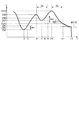
図4は、超音波振動によって把持される処置対象を凝固しながら切開している状態での超音波振動子25のインピーダンスZの経時的な変化の一例を示す図である。図4では、縦軸にインピーダンスZを示し、横軸に時間tを示す。図4に示す一例では、時間t1までは、インピーダンスZは漸増する。そして、インピーダンスZは、漸増した後の時間t1において、漸減を開始する。したがって、時間t1が、インピーダンスZが漸増した後に漸減を開始する漸減開始時となる。また、図4の一例では、時間t1又はその直近で、処置対象において把持される範囲の全体が、切れ分かれる。
FIG. 4 is a diagram illustrating an example of a change with time of the impedance Z of the
また、図4の一例では、漸減開始時である時間t1から所定の時間Tth経過した時点が時間t2となる。そして、時間t2より後の時間t3において、インピーダンスZ(t3)の時間変化率ΔZ(t3)が、所定の閾値ΔZthより大きくなる。すなわち、時間t3において、時間変化率ΔZ(t)が所定の閾値ΔZth以下の状態から時間変化率ΔZ(t)が所定の閾値ΔZthより大きい状態に、切替わる。そして、図4の一例では、時間t3において、摩擦熱によるパッド部材21の変形は、ほとんど発生していない。なお、図4の一例では、時間t2での時間変化率ΔZ(t2)は、所定の閾値ΔZth以下である。また、図4では、時間t2におけるインピーンスZ(t)の接線M(t2)、及び、時間t3におけるインピーダンスZ(t)の接線M(t3)が示される。そして、接線M(t2)の傾きが時間t2での時間変換ΔZ(t2)となり、接線M(t3)の傾きが時間t3での時間変化率ΔZ(t3)となる。
In addition, in the example of FIG. 4, a time point when a predetermined time Tth has elapsed from the time t1 when the gradual decrease is started is the time t2. Then, at time t3 after time t2, the time change rate ΔZ (t3) of the impedance Z (t3) becomes larger than a predetermined threshold value ΔZth. That is, at time t3, the state is changed from a state where the time change rate ΔZ (t) is equal to or smaller than the predetermined threshold value ΔZth to a state where the time change rate ΔZ (t) is larger than the predetermined threshold value ΔZth. In the example of FIG. 4, at time t3, deformation of the
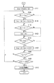
図5は、操作ボタン33での操作入力に基づくエネルギー制御装置3のプロセッサ35での処理を示すフローチャートである。図5に示すように、プロセッサ35の出力制御部45は、スイッチ37がON状態であるか否かに基づいて、操作ボタン33で操作入力が行われたか否か、すなわち操作ボタン33での操作入力がONか又はOFFかを判断する(ステップS101)。操作入力が行われていない場合は(ステップS101−No)、処理は、ステップS101に戻る。すなわち、プロセッサ(制御部)35は、操作ボタン33で操作入力が行われるまで、待機する。
FIG. 5 is a flowchart showing the processing in the
操作入力が行われると(ステップS101−Yes)、プロセッサ35は、判断パラメータであるインピーダンス最大値Zmax及びカウント時間Tをゼロにリセットする(ステップS102)。そして、プロセッサ35の出力制御部45は、エネルギー出力源47から超音波振動子25への電気エネルギーの出力を開始させる(ステップS103)。超音波振動子25へ電気エネルギーの出力が開始された後、所定の条件を満たすと、プロセッサ35の出力制御部45は、エネルギー出力源47から出力される電気エネルギーについてPLL(Phase Locked Loop)制御を開始する(ステップS104)。PLL制御によって、出力電流Iと出力電圧Vとの間の位相差が所定の閾値より小さくなる状態に、エネルギー出力源47からの電気エネルギーの出力における周波数が調整される。
When the operation input is performed (Yes at Step S101), the
PLL制御が開始されると、プロセッサ35の特性値検出部41は、電気エネルギーの電気特性値として超音波振動子25のインピーダンスZの検出を開始する。また、PLL制御の開始時又はその直後において、プロセッサ35は、インピーダンス最大値ZmaxをインピーダンスZ(t)に設定し、カウント時間Tをゼロにリセットする(ステップS105)。PLL制御の開始時以後においては、プロセッサ35の出力制御部45は、出力電流Iの電流値を経時的に一定に保つ前述した定電流制御で、エネルギー出力源47からの電気エネルギーの出力を制御する。出力電流Iの電流値が経時的に一定に保たれることにより、超音波振動子25で発生する超音波振動の振幅及び振動速度も経時的に略一定になり、第1の把持片15での超音波振動の振幅及び振動速度も経時的に略一定になる。
When the PLL control is started, the characteristic
また、PLL制御の開始時より後において、プロセッサ35の漸減検出部42は、特性値検出部41でのインピーダンスZの検出結果に基づいて、時間tでのインピーダンスZ(t)が、設定されているインピーダンス最大値Zmaxより大きいか否かを判断する(ステップS106)。インピーダンスZ(t)がインピーダンス最大値Zmaxより大きい場合は(ステップS106−Yes)、プロセッサ35は、時間tのインピーダンスZ(t)にインピーダンス最大値Zmaxを更新し、カウント時間Tをゼロにリセットする(ステップS107)。そして、処理は、ステップS108に進む。一方、インピーダンスZ(t)がインピーダンス最大値Zmax以下の場合は(ステップS106−No)、プロセッサ35は、インピーダンス最大値Zmaxを更新することなく保持し、カウント時間Tをゼロにリセットしない。そして、処理は、ステップS108に進む。ステップS106,S107の処理が行われることにより、プロセッサ35の漸減検出部42は、インピーダンスZ(t)がインピーダンス最大値Zmaxより大きい状態からインピーダンスZ(t)がインピーダンス最大値Zmax以下の状態に切替わった時点を、インピーダンスZが漸増した後に漸減を開始する漸減開始時として検出する。
Further, after the start of the PLL control, the gradual
そして、プロセッサ35の出力制御部45は、カウント時間Tが所定の時間Tth以上であるか否かを判断する(ステップS108)。カウント時間Tが所定の時間Tthより短い場合は(ステップS108−No)、処理は、ステップS106に戻る。そして、ステップS106以降の処理が順次行われる。一方、カウント時間Tが所定の時間Tth以上の場合は(ステップS108−Yes)、プロセッサ35の算出部43は、インピーダンスZ(t)の時間変化率ΔZ(t)を算出する。そして、プロセッサ35の出力制御部45は、算出された時間tでの時間変化率ΔZ(t)が、所定の閾値ΔZthより大きいか否かを判断する(ステップS109)。ここで、所定の閾値ΔZthは、負の値となり、ゼロに近い値に設定される。ある実施例では、所定の閾値ΔZthは、例えば−1である。
Then, the
なお、ある実施例では、エネルギー制御装置3にタッチパネル等の入力装置(図示しない)及びユーザーインターフェース(図示しない)が設けられ、所定の時間Tth及び所定の閾値ΔZthのそれぞれは、入力装置で術者によって設定される。また、別のある実施例では、超音波処置具2に記憶媒体(図示しない)が設けられ、記憶媒体に所定の時間Tth及び所定の閾値ΔZthが記憶される。この場合、超音波処置具2がケーブル31を介してエネルギー制御装置3に接続されることにより、プロセッサ35は、超音波処置具2の記憶媒体から所定の時間Tth及び所定の閾値ΔZthを読取る。そして、プロセッサ35は、読取った所定の時間Tth及び所定の閾値ΔZthを自動設定する。また、所定の時間Tth及び所定の閾値ΔZthのそれぞれは、既定の値に定まったものでもよい。また、所定の時間Tth及び所定の閾値ΔZthのそれぞれは、インピーダンスZの経時的な変化等に基づいて設定されてもよい。また、ある実施例では、超音波処置具2の種類に対する所定の時間Tth及び所定の閾値ΔZthのそれぞれの関係を示すルックアップテーブル等が記憶媒体36に記憶されてもよい。この場合、超音波処置具2の記憶媒体(図示しない)にシリアル番号等の識別情報が記憶され、超音波処置具2がケーブル31を介してエネルギー制御装置3に接続されることにより、プロセッサ35は、超音波処置具2の記憶媒体から識別情報を読取る。そして、プロセッサ35は、読取った識別情報に基づいて、エネルギー制御装置3に接続される超音波処置具2の種類を検出する。そして、プロセッサ35は、検出した超音波処置具2の種類に対応する所定の時間Tth及び所定の閾値ΔZthを、ルックアップテーブルから読取り、読取った値に所定の時間Tth及び所定の閾値ΔZthのそれぞれを設定する。
In an embodiment, the energy control device 3 is provided with an input device (not shown) such as a touch panel and a user interface (not shown), and the predetermined time Tth and the predetermined threshold value ΔZth are determined by the operator using the input device. Is set by In another embodiment, a storage medium (not shown) is provided in the ultrasonic treatment device 2, and a predetermined time Tth and a predetermined threshold ΔZth are stored in the storage medium. In this case, the
また、ある実施例では、カウント時間Tが所定の時間Tthより短い場合においても、時間変化率ΔZ(t)の算出が行われ、例えばPLL制御の開始時から時間変化率ΔZ(t)の算出が行われてもよい。ただし、この場合も、カウント時間Tが所定の時間Tth以上になるまでは、時間変化率ΔZ(t)が、所定の閾値ΔZthより大きいか否かを判断するステップS109の処理が行われない。 Further, in one embodiment, even when the count time T is shorter than the predetermined time Tth, the time change rate ΔZ (t) is calculated. For example, the time change rate ΔZ (t) is calculated from the start of the PLL control. May be performed. However, also in this case, until the count time T becomes equal to or longer than the predetermined time Tth, the process of step S109 for determining whether the time change rate ΔZ (t) is larger than the predetermined threshold ΔZth is not performed.
時間変化率ΔZ(t)が所定の閾値ΔZthより大きいと判断した場合は(ステップS109−Yes)、プロセッサ35の出力制御部45は、エネルギー出力源47から超音波振動子25への電気エネルギーの出力を強制停止する(ステップS110)。一方、時間変化率ΔZ(t)が所定の閾値ΔZth以下であると判断した場合は(ステップS109−No)、処理は、ステップS106に戻る。そして、ステップS106以降の処理が順次行われる。
If it is determined that the time rate of change ΔZ (t) is greater than the predetermined threshold ΔZth (step S109—Yes), the
なお、ある実施例では、ステップS110においてエネルギー出力源47からの出力を停止する代わりに、出力制御部45は、時間変化率ΔZ(t)が所定の閾値ΔZthより大きいと判断された時点より前に比べて、エネルギー出力源47からの電気エネルギーの出力を低減させてもよい。この場合、出力制御部45は、時間変化率ΔZ(t)が所定の閾値ΔZthより大きいと判断された時点より前に比べて、エネルギー出力源47からの出力電流Iの電流値が小さくする。これにより、時間変化率ΔZ(t)が所定の閾値ΔZthより大きいと判断された時点より前に比べて、超音波振動子25で発生する超音波振動の振幅及び振動速度が小さくなり、第1の把持片15での超音波振動の振幅及び振動速度が小さくなる。第1の把持片15での超音波振動の振幅及び振動速度が小さくなることにより、把持される処置対象の超音波振動による切開性能が小さくなる。
Note that, in one embodiment, instead of stopping the output from the
また、別のある実施例では、ステップS110において、エネルギー出力源47からの電気エネルギーの出力を停止又は低減させる代わりに、又は、電気エネルギーの出力を停止又は低減させることに加えて、プロセッサ35は、告知部55を作動させてもよい。これにより、告知部55によって、時間変化率ΔZ(t)が所定の閾値ΔZthより大きくなったことが、告知される。なお、告知部55による告知のみが行われる場合、術者は、告知部55での告知に基づいて、操作ボタン33での操作入力を解除し、エネルギー出力源47から超音波振動子25への電気エネルギーの出力を停止する。
Further, in another embodiment, in step S110, instead of stopping or reducing the output of the electric energy from the
本実施形態では、前述のように図5に示す処理が行われる。このため、図4のようにインピーダンスZが経時的に変化すると、PLL制御の開始時又はその直後にステップS105の処理によって、インピーダンス最大値ZmaxがインピーダンスZ(t)に設定されるとともに、カウント時間Tがゼロにリセットされる。そして、時間t1までは、ステップS106、S107の処理によって、インピーダンスZ(t)にインピーダンス最大値Zmaxが継続して更新され、カウント時間Tは、継続してゼロにリセットされる。このため、時間t1までは、ステップS108の処理によって、カウント時間Tが所定の時間Tthより小さいと判断される。したがって、時間t1までは、時間変化率ΔZ(t)が所定の閾値ΔZthより大きいか否かを判断するステップS109の処理は、行われない。このため、漸減開始時である時間t1の前において、エネルギー出力源47からの電気エネルギーの出力は、停止されず、かつ低減されない。すなわち、処置対象において把持される範囲の一部のみが切れ分かれている状態において、エネルギー出力源47からの電気エネルギーの出力は、停止されず、かつ、低減されない。したがって、処置対象において把持される範囲の一部が切れ分かれずに切れ残ることが、有効に防止される。
In the present embodiment, the processing shown in FIG. 5 is performed as described above. For this reason, when the impedance Z changes over time as shown in FIG. 4, the maximum impedance Zmax is set to the impedance Z (t) by the process of step S105 at the start of or immediately after the PLL control, and the count time T is reset to zero. Until time t1, the impedance Z (t) is continuously updated with the impedance maximum value Zmax by the processing of steps S106 and S107, and the count time T is continuously reset to zero. For this reason, until the time t1, it is determined that the count time T is smaller than the predetermined time Tth by the process of step S108. Therefore, until time t1, the process of step S109 for determining whether or not the time change rate ΔZ (t) is larger than the predetermined threshold ΔZth is not performed. Therefore, before time t1, which is the start of the gradual decrease, the output of the electric energy from the
そして、時間t1の直後において、漸減検出部42が、ステップS106の処理によって、インピーダンスZ(t)がインピース最大値ZmaxであるインピーダンスZ(t1)以下であると、判断する。これにより、漸減検出部42は、時間t1をインピーダンスZの漸減開始時として検出する。また、時間t1以後において、プロセッサ35は、時間t1をゼロとするカウント時間Tをカウントする。時間t1以後においては、インピーダンスZは、継続して漸減する。このため、時間t1以後は、時間t1でのインピーダンスZ(t1)がインピーダンス最大値Zmaxとして保持され、カウント時間Tはゼロにリセットされない。
Then, immediately after the time t1, the gradual
そして、時間t1から所定の時間Tth経過した時点である時間t2より前においては、プロセッサ35は、ステップS108の処理によって、カウント時間Tが所定の時間Tthより小さいと判断する。したがって、時間t2までは、時間変化率ΔZ(t)が所定の閾値ΔZthより大きいか否かを判断するステップS109の処理は、行われない。ここで、漸減開始時である時間t1の直後では、インピーダンスZ(t)の単位時間当たりの減少量は小さく、時間変化率ΔZ(t)は、ゼロに近い値となる。このため、時間t1の直後では、時間変化率ΔZ(t)が所定の閾値ΔZthより大きくなる可能性がある。ただし、本実施形態では、時間t1から所定の時間Tth経過した時点である時間t2より前においては、ステップS109の判断は行われない。このため、漸減開始時である時間t1の直後において、エネルギー出力源47からの電気エネルギーの出力は、停止されず、かつ低減されない。漸減開始時から所定の時間Tthが経過するまで時間変化率ΔZ(t)に基づく判断が行われないことにより、漸減開始時が処置対象において把持される範囲の全体が切れ分かれた時点であるか否かが、適切に判断される。すなわち、インピーダンスZのピークが切れ分かれに起因するものであるか否かが、適切に判断される。
Then, before the time t2 when the predetermined time Tth has elapsed from the time t1, the
そして、時間t1から所定の時間Tth経過した時点である時間t2以後においては、ステップS109の処理によって、出力制御部45は、時間変化率ΔZ(t)が所定の閾値ΔZthより大きいか否かを判断する。ここで、時間t2においては、時間変化率ΔZ(t2)は、所定の閾値ΔZth以下であると判断される。このため、エネルギー出力源47からの電気エネルギーの出力は、低減されることなく維持される。また、時間t2では、告知部55による告知も、行われない。
Then, after the time t2, which is a point in time when the predetermined time Tth has elapsed from the time t1, the
そして、時間t3又はその直後において、ステップS109の処理によって、時間変化率ΔZ(t3)は、所定の閾値ΔZthより大きいと判断される。これにより、時間t3又はその直後に、ステップS110の処理によって、エネルギー出力源47からの電気エネルギーの出力が停止又は低減される。また、時間t3又はその直後に、告知部55が告知を行い、術者は、告知に基づいて、エネルギー出力源47からの電気エネルギーの出力を停止してもよい。なお、エネルギー出力源47からの電気エネルギーの出力が停止又は低減されるタイミングは、漸減開始時である時間t1より後であり、かつ、時間t1から所定の時間Tth経過した時点である時間t2以後である。
Then, at or immediately after the time t3, the time change rate ΔZ (t3) is determined to be greater than the predetermined threshold ΔZth by the processing of step S109. Thus, at or immediately after the time t3, the output of the electric energy from the
前述のように、図4の一例では、時間t3において、摩擦熱によるパッド部材21の変形は、ほとんど発生していない。このため、時間t3又はその直後に、エネルギー出力源47からの電気エネルギーの出力が停止又は低減されることにより、処置対象において把持される範囲の全体が切れ分かれた後で、かつ、摩擦熱によってパッド部材21が変形する前に、エネルギー出力源47からの電気エネルギーの出力が停止又は低減される。すなわち、本実施形態では、大きい振幅及び振動速度で第1の把持片15が振動する状態において第1の把持片15へ第2の把持片16のパッド部材21が接触し続けることが、有効に防止され、第2の把持片16のパッド部材21の摩耗及び変形等が、有効に防止される。
As described above, in the example of FIG. 4, the deformation of the
前述のように、本実施形態では、処置対象が切れ分かれるタイミングが、適切に検出される。そして、検出された適切なタイミングに基づいて、エネルギー出力源47からの電気エネルギーの出力が停止又は低減される。
As described above, in the present embodiment, the timing at which the treatment target is cut off is appropriately detected. Then, based on the detected appropriate timing, the output of the electric energy from the
(第2の実施形態)
次に、本発明の第2の実施形態について図6乃至図8を参照にして説明する。第2の実施形態は、第1の実施形態の構成を次の通り変形したものである。なお、第1の実施形態と同一の部分については同一の符号を付して、その説明は省略する。(Second embodiment)
Next, a second embodiment of the present invention will be described with reference to FIGS. In the second embodiment, the configuration of the first embodiment is modified as follows. The same portions as those in the first embodiment are denoted by the same reference numerals, and description thereof will be omitted.
図6及び図7は、エネルギー制御装置3のプロセッサ35での処理を示すフローチャートである。図6及び図7に示すように、本実施形態でも第1の実施形態と同様に、操作入力が行われると(ステップS101−Yes)、プロセッサ35は、判断パラメータであるインピーダンス最大値Zmax及びカウント時間Tをゼロにリセットする(ステップS111)。さらに、本実施形態では、インピーダンス最大値Zmax及びカウント時間Tに加えて、インピーダンス最小値Zminが判断パラメータとして用いられる。インピーダンス最小値Zminは、条件により規定されたある時点からインピーダンスZ(t)になる時点までのインピーダンスZの最小値である。操作入力が行われると(ステップS101−Yes)、プロセッサ35は、インピーダンス最小値Zminもゼロにリセットする(ステップS111)。
FIG. 6 and FIG. 7 are flowcharts showing processing in the
そして、第1の実施形態と同様に、プロセッサ35の出力制御部45は、エネルギー出力源47から超音波振動子25への電気エネルギーの出力を開始させる(ステップS103)。そして、超音波振動子25へ電気エネルギーの出力が開始された後、所定の条件を満たすと、プロセッサ35の出力制御部45は、エネルギー出力源47から出力される電気エネルギーについてPLL制御を開始する(ステップS104)。また、本実施形態でも第1の実施形態と同様に、PLL制御が開始されると、特性値検出部41は、インピーダンスZの検出を開始し、出力制御部45は、出力電流Iの電流値を経時的に一定に保つ前述した定電流制御で、エネルギー出力源47からの電気エネルギーの出力を制御する。
Then, similarly to the first embodiment, the
本実施形態では、PLL制御が開始されると、プロセッサ35の漸減検出部42は、時間tでのインピーダンスZ(t)が、設定されているインピーダンス最大値Zmaxより大きいか否かを判断する(ステップS112)。インピーダンスZ(t)がインピーダンス最大値Zmaxより大きい場合は(ステップS112−Yes)、プロセッサ35は、時間tのインピーダンスZ(t)にインピーダンス最大値Zmaxを更新し、インピーダンスZ(t)にインピーダンス最小値Zminを更新する(ステップS113)。そして、処理は、ステップS114に進む。一方、インピーダンスZ(t)がインピーダンス最大値Zmax以下の場合は(ステップS112−No)、プロセッサ35は、インピーダンス最大値Zmax及びインピーダンス最小値Zminのそれぞれを更新することなく保持する。そして、処理は、ステップS114に進む。
In the present embodiment, when the PLL control is started, the gradually decreasing
そして、プロセッサ35の漸増検出部46は、特性値検出部41でのインピーダンスZの検出結果に基づいて、時間tでのインピーダンスZ(t)が、設定されているインピーダンス最小値Zminより小さいか否かを判断する(ステップS114)。インピーダンスZ(t)がインピーダンス最小値Zminより小さい場合は(ステップS114−Yes)、プロセッサ35は、時間tのインピーダンスZ(t)にインピーダンス最小値Zminを更新する(ステップS115)。そして、処理は、ステップS116に進む。一方、インピーダンスZ(t)がインピーダンス最小値Zmin以上の場合は(ステップS114−No)、プロセッサ35は、インピーダンス最小値Zminを更新することなく保持する。そして、処理は、ステップS116に進む。ステップS114,S115の処理が行われることにより、プロセッサ35の漸増検出部46は、インピーダンスZ(t)がインピーダンス最小値Zminより小さい状態からインピーダンスZ(t)がインピーダンス最小値Zmin以上の状態に切替わった時点を、インピーダンスZが漸減した後に漸増を開始する漸増開始時として検出する。
Then, the gradual
そして、プロセッサ35の出力制御部45及び漸増検出部46は、時間tでのインピーダンスZ(t)から設定されているインピーダンス最小値Zminを減算した算出値(Z(t)−Zmin)が所定の閾値Zth1より大きいか否かを判断する(ステップS116)。ここで、所定の閾値Zth1は、正の値である。また、所定の閾値Zth1は、第1の実施形態で前述した所定の時間Tth及び所定の閾値ΔZthと同様にして、設定可能である。算出値(Z(t)−Zmin)が所定の閾値Zth1以下の場合は(ステップS116−No)、処理は、ステップS112に戻る。そして、ステップS112以降の処理が、順次行われる。一方、算出値(Z(t)−Zmin)が所定の閾値Zth1より大きい場合は(ステップS116−Yes)、プロセッサ35は、インピーダンス最大値ZmaxをインピーダンスZ(t)に更新し、インピーダンス最小値ZminをZ(t)に更新する(ステップS117)。
Then, the
ステップS117の処理が行われると、第1の実施形態のPLL開始時以後と同様に、漸減検出部42は、インピーダンスZ(t)が、設定されているインピーダンス最大値Zmaxより大きいか否かを判断する(ステップS106)。本実施形態でも、インピーダンスZ(t)がインピーダンス最大値Zmaxより大きい場合は(ステップS106−Yes)、プロセッサ35は、時間tのインピーダンスZ(t)にインピーダンス最大値Zmaxを更新し、カウント時間Tをゼロにリセットする(ステップS118)。また、本実施形態では、インピーダンスZ(t)がインピーダンス最大値Zmaxより大きい場合は(ステップS106−Yes)、インピーダンスZ(t)にインピーダンス最小値Zminを更新する(ステップS118)。そして、処理は、ステップS119に進む。一方、インピーダンスZ(t)がインピーダンス最大値Zmax以下の場合は(ステップS106−No)、プロセッサ35は、インピーダンス最大値Zmax及びインピーダンス最小値Zminのそれぞれを更新することなく保持し、カウント時間Tをゼロにリセットしない。そして、処理は、ステップS119に進む。ステップS106,S118の処理が行われることにより、第1の実施形態と同様に、プロセッサ35の漸減検出部42は、インピーダンスZ(t)がインピーダンス最大値Zmaxより大きい状態からインピーダンスZ(t)がインピーダンス最大値Zmax以下の状態に切替わった時点を、インピーダンスZが漸増した後に漸減を開始する漸減開始時として検出する。
When the processing in step S117 is performed, the gradual
そして、プロセッサ35の漸増検出部46は、時間tでのインピーダンスZ(t)が、設定されているインピーダンス最小値Zminより小さいか否かを判断する(ステップS119)。インピーダンスZ(t)がインピーダンス最小値Zminより小さい場合は(ステップS119−Yes)、プロセッサ35は、時間tのインピーダンスZ(t)にインピーダンス最小値Zminを更新する(ステップS120)。そして、処理は、ステップS121へ進む。一方、インピーダンスZ(t)がインピーダンス最小値Zmin以上の場合は(ステップS119−No)、プロセッサ35は、インピーダンス最小値Zminを更新することなく保持する。そして、処理は、ステップS121に進む。ステップS119,S120の処理が行われることにより、プロセッサ35の漸増検出部46は、インピーダンスZ(t)がインピーダンス最小値Zminより小さい状態からインピーダンスZ(t)がインピーダンス最小値Zmin以上の状態に切替わった時点を、インピーダンスZが漸減した後に漸増を開始する漸増開始時として検出する。
Then, the gradual
そして、プロセッサ35の出力制御部45及び漸増検出部46は、時間tでのインピーダンスZ(t)から設定されているインピーダンス最小値Zminを減算した算出値(Z(t)−Zmin)が所定の閾値Zth2より大きいか否かを判断する(ステップS121)。ここで、所定の閾値Zth2は、正の値である。所定の閾値Zth2は、所定の閾値Zth1と同一の値であってもよく、所定の閾値Zth2とは異なる値であってもよい。また、所定の閾値Zth2は、第1の実施形態で前述した所定の時間Tth及び所定の閾値ΔZthと同様にして、設定可能である。算出値(Z(t)−Zmin)が所定の閾値Zth2より大きい場合は(ステップS121−Yes)、プロセッサ35は、インピーダンス最大値ZmaxをインピーダンスZ(t)に更新し、インピーダンス最小値ZminをZ(t)に更新する(ステップS122)。また、算出値(Z(t)−Zmin)が所定の閾値Zth2より大きい場合は(ステップS121−Yes)、プロセッサ35は、カウント時間Tをゼロにリセットする(ステップS122)。そして、処理は、ステップS108へ進む。一方、算出値(Z(t)−Zmin)が所定の閾値Zth2以下の場合は(ステップS121−No)、プロセッサ35は、インピーダンス最大値Zmax及びインピーダンス最小値Zminのそれぞれを更新することなく保持し、カウント時間Tをゼロにリセットしない。そして、処理は、ステップS108に進む。
Then, the
そして、第1の実施形態のPLL開始時以後と同様に、プロセッサ35の出力制御部45は、カウント時間Tが所定の時間Tth以上であるか否かを判断する(ステップS108)。カウント時間Tが所定の時間Tthより短い場合は(ステップS108−No)、処理は、ステップS106に戻る。そして、ステップS106以降の処理が順次行われる。一方、カウント時間Tが所定の時間Tth以上の場合は(ステップS108−Yes)、第1の実施形態と同様に、プロセッサ35の出力制御部45は、算出された時間tでの時間変化率ΔZ(t)が、所定の閾値ΔZthより大きいか否かを判断する(ステップS109)。
Then, similarly to the time after the start of the PLL of the first embodiment, the
時間変化率ΔZ(t)が所定の閾値ΔZthより大きいと判断した場合は(ステップS109−Yes)、第1の実施形態と同様に、プロセッサ35の出力制御部45は、エネルギー出力源47から超音波振動子25への電気エネルギーの出力を強制停止する(ステップS110)。この際、第1の実施形態と同様に、エネルギー出力源47から超音波振動子25への電気エネルギーの出力を低減させてもよく、告知部55による告知を行ってもよい。また、電気エネルギーの出力の停止又は低減と告知部55による告知を組み合わせてもよい。一方、時間変化率ΔZ(t)が所定の閾値ΔZth以下であると判断した場合は(ステップS109−No)、処理は、ステップS106に戻る。そして、ステップS106以降の処理が順次行われる。
If it is determined that the time rate of change ΔZ (t) is greater than the predetermined threshold ΔZth (step S109-Yes), the
図8は、超音波振動によって把持される処置対象を凝固しながら切開している状態での超音波振動子25のインピーダンスZの経時的な変化の図4とは別の一例を示す図である。図8でも、縦軸にインピーダンスZを示し、横軸に時間tを示す。ここで、前述のように、PLL制御が開始されると、出力電流Iと出力電圧Vとの間の位相差が所定の閾値より小さくなる状態に、電気エネルギーの出力における周波数が調整される。このため、PLL制御の開始時からしばらくの間は、インピーダンスZは漸減することがある。この場合、PLL制御の開始時からしばらくの間インピーダンスZが漸減した後に、インピーダンスZが漸増する。図8の一例では、PLL制御の開始時から時間t4までは、インピーダンスZが漸減し、時間t4からしばらくの間は、インピーダンスZが漸増する。
FIG. 8 is a diagram illustrating another example of the temporal change of the impedance Z of the
本実施形態では、図6及び図7に示す処理が行われる。このため、図8のようにインピーダンスZが経時的に変化すると、PLL制御の開始時又はその直後に、ステップS112、S113の処理によって、インピーダンス最大値Zmax及びインピーダンス最小値ZminのそれぞれがインピーダンスZ(t)に更新される。そして、時間t4までは、ステップS114、S115の処理によって、インピーダンスZ(t)にインピーダンス最小値Zminが継続して更新される。このため、時間t4までは、算出値(Z(t)−Zmin)が負の値のなり、ステップS116の処理によって、算出値(Z(t)−Zmin)が所定の閾値Zth1以下であると判断される。したがって、時間t4までは、処理は、ステップS117に進まず、時間変化率ΔZ(t)が所定の閾値ΔZthより大きいか否かを判断するステップS109の処理は、行われない。 In the present embodiment, the processing shown in FIGS. 6 and 7 is performed. For this reason, when the impedance Z changes over time as shown in FIG. 8, the maximum impedance Zmax and the minimum impedance Zmin are respectively changed to the impedance Z (by the processing of steps S112 and S113 at or immediately after the start of the PLL control. Updated to t). Until time t4, the impedance Z (t) is continuously updated with the impedance minimum value Zmin by the processing of steps S114 and S115. Therefore, until time t4, the calculated value (Z (t) -Zmin) becomes a negative value, and as a result of the processing in step S116, the calculated value (Z (t) -Zmin) is equal to or smaller than the predetermined threshold value Zth1. Is determined. Therefore, until time t4, the process does not proceed to step S117, and the process of step S109 for determining whether or not the time change rate ΔZ (t) is greater than the predetermined threshold ΔZth is not performed.
図8の一例では、時間t4からインピーダンスZがしばらくの間継続して漸増し、時間t5においてインピーダンスZ(t5)は、時間t4のインピーダンスZ(t4)から所定の閾値Zth1増加した値となる。そして、時間t5からしばらくの間、インピーダンスZは、漸増する。本実施形態では、図6及び図7に示す処理が行われるため、時間t4からインピーダンスZが漸増している間は、ステップS114の処理によって、時間t4でのインピーダンスZ(t4)がインピーダンス最小値Zminとして保持される。そして、時間t5までは、算出値(Z(t)−Zmin)が所定の閾値Zth1以下であると判断される。したがって、時間t4までは、処理は、ステップS117に進まない。そして、時間t5又はその直後において、プロセッサ35は、算出値(Z(t)−Zmin)が所定の閾値Zth1より大きいと判断し、処理が、ステップS117に進む。そして、時間t5又はその直後において、ステップS117の処理によって、インピーダンス最大値Zmax及びインピーダンス最小値ZminのそれぞれがインピーダンスZ(t)に更新される。
In the example of FIG. 8, the impedance Z gradually increases for a while from time t4, and at time t5, the impedance Z (t5) becomes a value obtained by increasing the impedance Z (t4) at time t4 by a predetermined threshold value Zth1. Then, the impedance Z gradually increases for a while from the time t5. In the present embodiment, since the processes shown in FIGS. 6 and 7 are performed, while the impedance Z gradually increases from the time t4, the impedance Z (t4) at the time t4 becomes the minimum impedance by the process of step S114. It is held as Zmin. Until time t5, it is determined that the calculated value (Z (t) -Zmin) is equal to or smaller than a predetermined threshold value Zth1. Therefore, the process does not proceed to step S117 until time t4. Then, at or immediately after time t5, the
前述のように、本実施形態では、インピーダンスZがPLL制御の開始時からしばらくの間漸減した後に漸増した場合でも、インピーダンスZが漸増開始時からの増加量が所定の閾値Zth1より大きくなるまでは、処理はステップS117に進まない。すなわち、インピーダンスZが漸増開始時からある程度の増加量だけ増加するまでは、時間変化率ΔZ(t)が所定の閾値ΔZthより大きいか否かを判断するステップS109の処理は、行われない。したがって、PLL制御の開始時から超音波インピーダンスZが漸減している間において、エネルギー出力源47からの電気エネルギーの出力は、停止されず、かつ、低減されない。
As described above, in the present embodiment, even if the impedance Z gradually decreases for a while after the start of the PLL control and then gradually increases, the impedance Z does not increase until the amount of increase from the start of the gradually increasing becomes larger than the predetermined threshold value Zth1. Does not proceed to step S117. That is, the process of step S109 for determining whether the time rate of change ΔZ (t) is greater than the predetermined threshold ΔZth is not performed until the impedance Z increases by a certain amount from the start of the gradual increase. Therefore, while the ultrasonic impedance Z is gradually decreasing from the start of the PLL control, the output of the electric energy from the
また、把持される処置対象が厚い場合、又は、処置対象の濡れ度が高い場合は、処置対象の把持片15又は16との接触表面が切開され始めた瞬間に、インピーダンスZのピークが発生することがある。この場合、切れ分かれに起因する前述のピークより前に、処置対象の接触表面が切開され始めたこと起因するインピーダンスZのピークが発生する。図8に示す一例では、時間t10において切れ分かれに起因するインピーダンスZのピークが発生し、時間t10より前の時間t6においても、インピーダンスZのピークが発生する。そして、時間t6から時間t7までは、インピーダンスZが漸減し、時間t7から時間t10まではインピーダンスZが漸増する。
In addition, when the treatment target to be gripped is thick or the treatment target has a high wettability, a peak of the impedance Z occurs at the moment when the contact surface with the treatment
本実施形態では、図6及び図7に示す処理が行われるため、図8に示す一例では、時間t5の後において時間t6までは、ステップS106、S118の処理によって、インピーダンスZ(t)にインピーダンス最大値Zmaxが継続して更新され、カウント時間Tは、継続してゼロにリセットされる。また、時間t6までは、ステップS119においてインピーダンスZ(t)は、インピーダンス最小値Zmin以上と判断され、ステップS121において、算出値(Z(t)−Zmin)は、所定の閾値Zth2以下であると判断される。このため、時間t6までは、ステップS108の処理によって、カウント時間Tが所定の時間Tthより小さいと判断される。したがって、時間t6までは、時間変化率ΔZ(t)が所定の閾値ΔZthより大きいか否かを判断するステップS109の処理は、行われない。 In the present embodiment, since the processing shown in FIGS. 6 and 7 is performed, in the example shown in FIG. 8, the impedance Z (t) is added to the impedance Z (t) by the processing of steps S106 and S118 after time t5 until time t6. The maximum value Zmax is continuously updated, and the count time T is continuously reset to zero. Until time t6, the impedance Z (t) is determined to be equal to or more than the minimum impedance value Zmin in step S119, and in step S121, the calculated value (Z (t) -Zmin) is equal to or less than the predetermined threshold value Zth2. Is determined. Therefore, until the time t6, it is determined that the count time T is smaller than the predetermined time Tth by the process of step S108. Therefore, until time t6, the processing of step S109 for determining whether or not the time change rate ΔZ (t) is greater than the predetermined threshold ΔZth is not performed.
そして、時間t6の直後において、漸減検出部42が、ステップS106の処理によって、インピーダンスZ(t)がインピース最大値ZmaxであるインピーダンスZ(t6)以下であると、判断する。これにより、漸減検出部42は、時間t6をインピーダンスZの漸減開始時として検出する。これにより、カウント時間Tが、カウントアップされる。
Immediately after the time t6, the gradual
また、図8の一例では、時間t7からインピーダンスZがしばらくの間継続して漸増し、時間t8においてインピーダンスZ(t8)は、時間t7のインピーダンスZ(t7)から所定の閾値Zth2増加した値となる。そして、時間t8からしばらくの間、インピーダンスZは、漸増する。また、漸減開始時である時間t6から所定の時間Tth経過した時点である時間t9を規定する。時間t7及び時間t8は、時間t9より前である。 In the example of FIG. 8, the impedance Z gradually increases for a while from time t7, and at time t8, the impedance Z (t8) is a value obtained by increasing the impedance Z (t7) at time t7 by a predetermined threshold value Zth2. Become. Then, for a while from time t8, the impedance Z gradually increases. In addition, a time t9, which is a point in time when a predetermined time Tth has elapsed from the time t6, which is the start of the gradual decrease, is defined. Time t7 and time t8 are before time t9.
本実施形態では、図6及び図7に示す処理が行われるため、時間t6より後において時間t7までは、ステップS119、S120の処理によって、インピーダンスZ(t)にインピーダンス最小値Zminが継続して更新される。そして、時間t7からインピーダンスZが漸増している間は、ステップS119の処理によって、時間t7でのインピーダンスZ(t7)がインピーダンス最小値Zminとして保持される。そして、時間t8までは、算出値(Z(t)−Zmin)が所定の閾値Zth2以下であると判断される。ここで、時間t8は、漸減開始時(時間t6)から所定の時間Tth経過した時点である時間9より前である。このため、時間t8までは、ステップS108の処理によって、カウント時間Tが所定の時間Tthより小さいと判断される。したがって、時間t8までは、時間変化率ΔZ(t)が所定の閾値ΔZthより大きいか否かを判断するステップS109の処理は、行われない。 In the present embodiment, since the processes shown in FIGS. 6 and 7 are performed, the impedance Z (t) is continuously reduced to the impedance Z (t) by the processes of steps S119 and S120 after time t6 until time t7. Be updated. Then, while the impedance Z gradually increases from the time t7, the impedance Z (t7) at the time t7 is held as the impedance minimum value Zmin by the process of step S119. Until time t8, it is determined that the calculated value (Z (t) -Zmin) is equal to or less than a predetermined threshold value Zth2. Here, the time t8 is before the time 9 when a predetermined time Tth has elapsed from the start of the gradual decrease (time t6). Therefore, until the time t8, it is determined that the count time T is smaller than the predetermined time Tth by the process of step S108. Therefore, until time t8, the process of step S109 for determining whether or not the time change rate ΔZ (t) is larger than the predetermined threshold ΔZth is not performed.
そして、時間t8又はその直後において、プロセッサ35は、算出値(Z(t)−Zmin)が所定の閾値Zth2より大きいと判断する。そして、時間t8又はその直後において、ステップS122の処理によって、インピーダンス最大値Zmax及びインピーダンス最小値ZminのそれぞれがインピーダンスZ(t)に更新されるとともに、カウント時間Tがゼロにリセットされる。
Then, at or immediately after time t8, the
また、時間t8と時間t10との間においては、ステップS106、S118の処理によって、インピーダンスZ(t)にインピーダンス最大値Zmaxが継続して更新され、カウント時間Tは、継続してゼロにリセットされる。また、時間t10までは、ステップS119においてインピーダンスZ(t)は、インピーダンス最小値Zmin以上と判断され、ステップS121において、算出値(Z(t)−Zmin)は、所定の閾値Zth2以下であると判断される。このため、時間t10までは、ステップS108の処理によって、カウント時間Tが所定の時間Tthより小さいと判断される。したがって、時間t10までは、時間変化率ΔZ(t)が所定の閾値ΔZthより大きいか否かを判断するステップS109の処理は、行われない。 Also, between the time t8 and the time t10, the impedance Z (t) is continuously updated with the impedance maximum value Zmax by the processing of steps S106 and S118, and the count time T is continuously reset to zero. You. Until time t10, it is determined in step S119 that the impedance Z (t) is equal to or greater than the minimum impedance Zmin, and in step S121, the calculated value (Z (t) -Zmin) is equal to or less than the predetermined threshold Zth2. Is determined. Therefore, until the time t10, it is determined that the count time T is smaller than the predetermined time Tth by the process of step S108. Therefore, until time t10, the process of step S109 for determining whether or not the time change rate ΔZ (t) is greater than the predetermined threshold value ΔZth is not performed.
前述のように本実施形態では、インピーダンスZの漸減開始時から所定の時間経過Tthするまでの間において、インピーダンスZの漸増開始時を検出するそして、漸増開始時が検出され、かつ、漸増開始時からのインピーダンスZの増加量が所定の増加量(Zth2)より大きくなった場合は、プロセッサ35は、インピーダンスZが再び漸減を開始するまで、時間変化率ΔZが所定の閾値ΔZthより大きいか否かの判断を行わない。このため、本実施形態では、切れ分かれに起因するインピーダンスZのピークより前に別のピークが発生した場合でも、別のピークの発生時から所定の時間Tth経過する前に所定の閾値Zth2より大きい増加量だけインピーダンスZが漸増すれば、時間変化率ΔZ(t)が所定の閾値ΔZthより大きいか否かを判断するステップS109の処理は、行われない。したがって、切れ分かれに起因するインピーダンスZのピークの発生時より前において、別のピークに起因してエネルギー出力源47からの電気エネルギーの出力が停止又は低減されることが、有効に防止される。
As described above, in the present embodiment, during the period from the start of the gradual decrease of the impedance Z to the lapse of a predetermined time Tth, the start of the gradual increase of the impedance Z is detected, and the start of the gradual increase is detected. When the increase amount of the impedance Z from the threshold value becomes larger than the predetermined increase amount (Zth2), the
また、図8の一例では、時間t10以後において、インピーダンスZが再び漸減する。そして、漸減開始時である時間t10から所定の時間Tth経過した時点が時間t11となる。そして、時間t11より後の時間t12において、インピーダンスZ(t12)の時間変化率ΔZ(t12)が、所定の閾値ΔZthより大きくなる。また、図8の一例では、時間t10又はその直近で、処置対象において把持される範囲の全体が切れ分かれ、時間t12において、摩擦熱によるパッド部材21の変形は、ほとんど発生していない。なお、図8の一例では、時間t11での時間変化率ΔZ(t11)は、所定の閾値ΔZth以下である。また、図8では、時間t11におけるインピーンスZ(t)の接線M(t11)、及び、時間t12におけるインピーダンスZ(t)の接線M(t12)が示される。
In the example of FIG. 8, after time t10, the impedance Z gradually decreases again. Then, a point in time when a predetermined time Tth has elapsed from the time t10, which is the start of the gradual decrease, is the time t11. Then, at time t12 after time t11, the time change rate ΔZ (t12) of the impedance Z (t12) becomes larger than a predetermined threshold value ΔZth. In addition, in the example of FIG. 8, the entire area grasped by the treatment target is cut at or immediately before time t10, and the deformation of the
本実施形態では、図6及び図7の処理が行われる。このため、図8の一例では、時間t10の直後において、漸減検出部42が、ステップS106の処理によって、インピーダンスZ(t)がインピース最大値ZmaxであるインピーダンスZ(t10)以下であると、判断する。これにより、漸減検出部42は、時間t10をインピーダンスZの漸減開始時として更新する。すなわち、漸増開始時からのインピーダンスZの増加量が所定の増加量(Zth2)より大きくなった後において、インピーダンスZが再び漸減を開始したことに基づいて、漸減検出部42は、再び漸減を開始した時点に漸減開始時を更新する。
In the present embodiment, the processing of FIGS. 6 and 7 is performed. For this reason, in the example of FIG. 8, immediately after the time t10, the gradual
そして、時間t10以後においては、図4の一例の時間t1以後と同様の処理が行われる。したがって、図8の一例では、更新された漸減開始時(t10)から所定の時間Tth経過した時点である時間t11より前においては、ステップS109の判断は行われない。そして、時間t11以後においては、ステップS109の処理によって、出力制御部45は、時間変化率ΔZ(t)が所定の閾値ΔZthより大きいか否かを判断する。時間t11においては、接線M(t11)の傾きである時間変化率ΔZ(t11)は、所定の閾値ΔZth以下であると判断される。このため、エネルギー出力源47からの電気エネルギーの出力は、低減されることなく維持される。また、時間t11では、告知部55による告知も、行われない。
Then, after time t10, the same processing as after time t1 in the example of FIG. 4 is performed. Therefore, in the example of FIG. 8, the determination in step S109 is not performed before the time t11 when a predetermined time Tth has elapsed from the updated gradually decreasing start time (t10). Then, after the time t11, the
そして、時間t12又はその直後において、ステップS109の処理によって、接線M(t12)の傾きである時間変化率ΔZ(t12)は、所定の閾値ΔZthより大きいと判断される。これにより、時間t12又はその直後に、ステップS110の処理によって、エネルギー出力源47からの電気エネルギーの出力が停止又は低減される。また、時間t12又はその直後に、告知部55が告知を行ってもよい。
Then, at or immediately after time t12, by the process of step S109, it is determined that the time change rate ΔZ (t12), which is the slope of the tangent M (t12), is larger than the predetermined threshold value ΔZth. Thus, at or immediately after the time t12, the output of the electric energy from the
図8の一例では、前述のように、時間t12において、摩擦熱によるパッド部材21の変形は、ほとんど発生していない。このため、時間t12又はその直後にエネルギー出力源47からの電気エネルギーの出力が停止又は低減されることにより、処置対象において把持される範囲の全体が切れ分かれた後で、かつ、摩擦熱によってパッド部材21が変形する前に、エネルギー出力源47からの電気エネルギーの出力が停止又は低減される。
In the example of FIG. 8, as described above, the deformation of the
前述のように、本実施形態では、インピーダンスZがPLL制御の開始時からしばらくの間漸減した後に漸増した場合、及び、切れ分かれに起因するインピーダンスZのピークより前に別のピークが発生した場合のそれぞれにおいても、処置対象が切れ分かれるタイミングが、適切に検出される。そして、検出された適切なタイミングに基づいて、エネルギー出力源47からの電気エネルギーの出力が停止又は低減される。
As described above, in the present embodiment, when the impedance Z gradually decreases for a while after the start of the PLL control and then gradually increases, and when another peak occurs before the peak of the impedance Z caused by the disconnection. In each case, the timing at which the treatment target is cut off is appropriately detected. Then, based on the detected appropriate timing, the output of the electric energy from the
(変形例)
なお、ある変形例では、図6及び図7においてステップS112〜S116の処理が行われず、代わりにカウント時間Tとは別のカウント時間T´に基づく処理が行われる。この場合、カウント時間T´は、PLL制御の開始時がゼロとなり、PLL制御の開始時からの経過時間を示す。本変形例では、ステップS104においてPLL制御が開始されると、プロセッサ35は、カウント時間T´が所定の時間T´th以上であるか否かを判断する。そして、カウント時間T´が所定の時間T´th以上の場合のみ、処理は、ステップS117に進む。これにより、PLL制御の開始時から所定の時間T´th経過するまでは、時間変化率ΔZ(t)が所定の閾値ΔZthより大きいか否かを判断するステップS109の処理は、行われない。したがって、本変形例でも第2の実施形態と同様に、PLL制御の開始時から超音波インピーダンスZが漸減している間において、エネルギー出力源47からの電気エネルギーの出力は、停止されず、かつ、低減されない。なお、所定の時間T´thは、前述した所定の時間Tth及び所定の閾値ΔZth等と同様にして、設定可能である。(Modification)
In a modification, the processes of steps S112 to S116 are not performed in FIGS. 6 and 7, and a process based on a count time T ′ different from the count time T is performed instead. In this case, the count time T ′ is zero when the PLL control is started, and indicates the elapsed time from the start of the PLL control. In the present modification, when the PLL control is started in step S104, the
また、ある変形例では、時間変化率ΔZ(t)が所定の閾値ΔZthより大きいか否かを判断するステップS109の処理をプロセッサ35が行う状態とプロセッサ35がステップS109の処理を行わない状態との間が、術者の操作によって切替えられる。この場合、エネルギー制御装置3にタッチパネル等の入力装置(図示しない)及びユーザーインターフェース(図示しない)が設けられる。そして、入力装置での操作に基づいて、時間変化率ΔZ(t)が所定の閾値ΔZthより大きいか否かの判断をプロセッサ35が行うか否かが、切替えられる。なお、プロセッサ35がステップS109の判断を行わない状態では、時間変化率ΔZに基づいて、エネルギー出力源47からの電気エネルギーの出力は、停止されず、かつ、低減されない。
Further, in a modified example, a state in which the
また、ある変形例では、インピーダンスZの代わりに又はインピーダンスZに加えて、エネルギー出力源47から超音波振動子25への出力電圧V及び出力電力Pのいずれかが、エネルギー出力源47から出力される電気エネルギーの電気特性値として用いられてもよい。前述のように、エネルギー出力源47から超音波振動子25に電気エネルギーが供給されている状態では、出力電流Iの電流値を経時的に一定に保つ定電流制御で、エネルギー出力源47からの電気エネルギーの出力が制御される。そして、定電流制御では、インピーダンスZの変化に対応させて、出力電圧V及び出力電力Pを調整する。このため、PLL制御の開始時以後においては、出力電圧V及び出力電力Pのそれぞれの経時的な変化は、インピーダンスZの経時的な変化と同様の傾向を示す。したがって、インピーダンスZの代わりに出力電圧V及び出力電力Pのいずれかを用いて、図3に示す処理、及び、図6及び図7に示す処理が行われても、前述の実施形態等と同様の作用及び効果を奏する。この場合、時間変化率ΔZの代わりに、出力電圧Vの時間変化率ΔV及び出力電力Pの時間変化率ΔPのいずれかが用いられる。また、所定の閾値ΔZthの代わりに、所定の閾値ΔVth及び所定の閾値ΔPthが用いられる。
In a modification, any one of the output voltage V and the output power P from the
また、ある変形例では、エネルギー出力源47は、超音波振動子25に電気エネルギーを出力することに加えて、超音波振動子25に供給される電気エネルギーとは別の電気エネルギーを超音波処置具2に出力してもよい。この場合、例えば、第1の把持片15及び第2の把持片16のホルダ部材22に、高周波電力が電気エネルギーとしてエネルギー出力源47から供給される。これにより、把持される処置対象を通して第1の把持片15とホルダ部材22との間に高周波電流が流れる。高周波電流によって発生する熱により、処置対象が変性され、凝固が促進される。
In a modification, in addition to outputting electric energy to the
前述の実施形態等のエネルギー制御装置(3)では、漸減検出部(42)は、エネルギー出力源(47)から超音波振動子(25)へ出力される電気エネルギーに関する電気特性値(Z;V;P)の検出結果に基づいて、電気特性値(Z;V;P)が漸増した後に漸減を開始する漸減開始時を検出する。制御部(45)は、漸減開始時より後において電気特性値(Z;V;P)の時間変化率(ΔZ;ΔV;ΔP)が所定の閾値(ΔZth;ΔVth;ΔPth)より大きくなったことに基づいて、エネルギー出力源(47)に超音波振動子(25)への電気エネルギーの出力を停止又は低減させること、及び、時間変化率(ΔZ;ΔV;ΔP)が所定の閾値(ΔZth;ΔVth;ΔPth)より大きくなったことを告知することの少なくとも一方を行う。 In the energy control device (3) according to the above-described embodiment and the like, the gradual decrease detection unit (42) includes the electric characteristic value (Z; V) related to the electric energy output from the energy output source (47) to the ultrasonic transducer (25). P), based on the detection result, detects when the electrical characteristic value (Z; V; P) gradually increases and then starts to gradually decrease. The control unit (45) determines that the time change rate (ΔZ; ΔV; ΔP) of the electric characteristic value (Z; V; P) has become larger than a predetermined threshold value (ΔZth; ΔVth; ΔPth) after the start of the gradual decrease. The energy output source (47) to stop or reduce the output of electrical energy to the ultrasonic transducer (25), and the time rate of change (ΔZ; ΔV; ΔP) to a predetermined threshold (ΔZth; ΔVth; ΔPth).
以上、本発明の実施形態等について説明したが、本発明は前述の実施形態等に限定されるものではなく、本発明の要旨を逸脱しない範囲で種々の変形ができることは勿論である。 Although the embodiments of the present invention have been described above, the present invention is not limited to the above-described embodiments and the like, and needless to say, various modifications can be made without departing from the gist of the present invention.
Claims (10)
前記超音波振動子へ前記電気エネルギーを出力するエネルギー出力源と、
前記超音波振動子へ出力される前記電気エネルギーに関する電気特性値を検出する特性値検出部と、
前記特性値検出部での検出結果に基づいて、前記電気特性値が漸増した後に漸減を開始する漸減開始時を検出する漸減検出部と、
前記電気特性値の時間変化率を算出する算出部と、
前記漸減開始時より後において前記電気特性値の前記時間変化率が所定の閾値より大きくなったことに基づいて、前記エネルギー出力源に前記超音波振動子への前記電気エネルギーの出力を停止又は低減させること、及び、前記時間変化率が前記所定の閾値より大きくなったことを術者に報知することの少なくとも一方を行う制御部と、
を具備するエネルギー制御装置。 Ultrasonic transducer that generates ultrasonic vibration by the supply of electrical energy, and an end effector that performs treatment using the ultrasonic vibration generated by the ultrasonic transducer, used with an ultrasonic treatment tool Energy control device,
An energy output source that outputs the electric energy to the ultrasonic transducer,
A characteristic value detection unit that detects an electric characteristic value related to the electric energy output to the ultrasonic transducer,
Based on the detection result in the characteristic value detection unit, a gradual decrease detection unit that detects a gradual decrease start time when the electrical characteristic value gradually starts to decrease after a gradual increase,
A calculating unit that calculates a time change rate of the electric characteristic value,
The energy output source stops or reduces the output of the electrical energy to the ultrasonic vibrator based on that the time rate of change of the electrical characteristic value becomes greater than a predetermined threshold after the start of the gradual decrease. And a control unit that performs at least one of notifying an operator that the time change rate has become larger than the predetermined threshold,
An energy control device comprising:
前記算出部は、前記漸増開始時からの前記電気特性値の増加量を算出し、
前記制御部は、前記漸減開始時から前記所定の時間経過するまでの間において、前記漸増開始時が検出され、かつ、前記漸増開始時からの前記電気特性値の前記増加量が所定の増加量より大きくなった場合は、前記電気特性値が再び漸減を開始するまで、前記時間変化率が前記所定の閾値より大きいか否かの判断を行わない、
請求項2のエネルギー制御装置。 The electrical characteristic value further includes a gradual increase detection unit that detects a gradual increase start time when the gradual increase starts,
The calculation unit calculates an increase amount of the electrical characteristic value from the time of the gradually increasing start,
The control unit is configured to detect the start of the gradual increase during the time from the start of the gradual decrease to the lapse of the predetermined time, and to increase the increase amount of the electrical characteristic value from the start of the gradual increase by a predetermined increase amount. If it has become larger, until the electrical characteristic value starts to gradually decrease again, it is not determined whether the time change rate is greater than the predetermined threshold,
The energy control device according to claim 2.
前記超音波振動子及び前記エンドエフェクタを備える前記超音波処置具と、
を具備する処置システム。 An energy control device according to claim 1,
The ultrasonic treatment tool including the ultrasonic transducer and the end effector,
Treatment system comprising:
前記第2の把持片は、前記第1の把持片と前記第2の把持片との間が閉じた状態において前記第1の把持片に当接可能なパッド部材を備える、
請求項6の処置システム。 The end effector includes a first gripping piece to which the ultrasonic vibration is transmitted, and a second gripping piece that can be opened and closed between the first gripping piece,
The second gripping piece includes a pad member that can abut on the first gripping piece in a state where the space between the first gripping piece and the second gripping piece is closed,
The treatment system according to claim 6.
前記制御部は、前記超音波処置具が前記エネルギー制御装置に接続されることにより、前記記憶媒体から前記所定の閾値を読取る、
請求項6の処置システム。 The ultrasonic treatment device includes a storage medium in which the predetermined threshold is stored,
The control unit is configured to read the predetermined threshold from the storage medium by the ultrasonic treatment tool being connected to the energy control device,
The treatment system according to claim 6.
前記制御部は、前記超音波処置具が前記エネルギー制御装置に接続されることにより、前記記憶媒体から前記識別情報を読取り、読取った前記識別情報に基づいて前記所定の閾値を設定する、
請求項6の処置システム。 The ultrasonic treatment device includes a storage medium in which identification information for identifying a type of the ultrasonic treatment device connected to the energy control device is stored,
The control unit, the ultrasonic treatment tool is connected to the energy control device, reads the identification information from the storage medium, and sets the predetermined threshold based on the read identification information,
The treatment system according to claim 6.
前記エネルギー制御装置が、前記超音波振動子へ前記電気エネルギーを出力することと、
前記超音波振動子へ出力される前記電気エネルギーに関する電気特性値を検出することと、
前記電気特性値の検出結果に基づいて、前記電気特性値が漸増した後に漸減を開始する漸減開始時を検出することと、
前記電気特性値の時間変化率を算出することと、
前記漸減開始時より後において前記電気特性値の前記時間変化率が所定の閾値より大きくなったことに基づいて、前記エネルギー制御装置が、前記超音波振動子への前記電気エネルギーの出力を停止又は低減させること、及び、前記時間変化率が前記所定の閾値より大きくなったことを術者に報知することの少なくとも一方を行うことと、
を具備する作動方法。 Ultrasonic transducer that generates ultrasonic vibration by the supply of electrical energy, and an end effector that performs treatment using the ultrasonic vibration generated by the ultrasonic transducer, used with an ultrasonic treatment tool Operating method of the energy control device,
The energy control device outputs the electric energy to the ultrasonic transducer,
Detecting an electrical characteristic value related to the electrical energy output to the ultrasonic transducer,
Based on the detection result of the electrical characteristic value, to detect a gradual start time to start gradual decrease after the electrical characteristic value gradually increases,
Calculating a time rate of change of the electrical characteristic value;
The energy control device stops the output of the electrical energy to the ultrasonic vibrator based on the time change rate of the electrical characteristic value being greater than a predetermined threshold after the start of the gradual decrease or Reducing, and performing at least one of notifying the operator that the time change rate has become greater than the predetermined threshold,
An operating method comprising:
Applications Claiming Priority (1)
| Application Number | Priority Date | Filing Date | Title |
|---|---|---|---|
| PCT/JP2016/071866 WO2018020577A1 (en) | 2016-07-26 | 2016-07-26 | Energy control device and treatment system |
Publications (2)
| Publication Number | Publication Date |
|---|---|
| JPWO2018020577A1 JPWO2018020577A1 (en) | 2019-05-16 |
| JP6665299B2 true JP6665299B2 (en) | 2020-03-13 |
Family
ID=61016981
Family Applications (1)
| Application Number | Title | Priority Date | Filing Date |
|---|---|---|---|
| JP2018530233A Active JP6665299B2 (en) | 2016-07-26 | 2016-07-26 | Energy control device, treatment system, and method of operating energy control device |
Country Status (3)
| Country | Link |
|---|---|
| US (1) | US11583309B2 (en) |
| JP (1) | JP6665299B2 (en) |
| WO (1) | WO2018020577A1 (en) |
Families Citing this family (82)
| Publication number | Priority date | Publication date | Assignee | Title |
|---|---|---|---|---|
| US11871901B2 (en) | 2012-05-20 | 2024-01-16 | Cilag Gmbh International | Method for situational awareness for surgical network or surgical network connected device capable of adjusting function based on a sensed situation or usage |
| US11504192B2 (en) | 2014-10-30 | 2022-11-22 | Cilag Gmbh International | Method of hub communication with surgical instrument systems |
| US11311342B2 (en) | 2017-10-30 | 2022-04-26 | Cilag Gmbh International | Method for communicating with surgical instrument systems |
| US11564756B2 (en) | 2017-10-30 | 2023-01-31 | Cilag Gmbh International | Method of hub communication with surgical instrument systems |
| US11045197B2 (en) | 2017-10-30 | 2021-06-29 | Cilag Gmbh International | Clip applier comprising a movable clip magazine |
| US11510741B2 (en) | 2017-10-30 | 2022-11-29 | Cilag Gmbh International | Method for producing a surgical instrument comprising a smart electrical system |
| US11793537B2 (en) | 2017-10-30 | 2023-10-24 | Cilag Gmbh International | Surgical instrument comprising an adaptive electrical system |
| US11317919B2 (en) | 2017-10-30 | 2022-05-03 | Cilag Gmbh International | Clip applier comprising a clip crimping system |
| US11291510B2 (en) | 2017-10-30 | 2022-04-05 | Cilag Gmbh International | Method of hub communication with surgical instrument systems |
| US11911045B2 (en) | 2017-10-30 | 2024-02-27 | Cllag GmbH International | Method for operating a powered articulating multi-clip applier |
| US11801098B2 (en) | 2017-10-30 | 2023-10-31 | Cilag Gmbh International | Method of hub communication with surgical instrument systems |
| US11464559B2 (en) | 2017-12-28 | 2022-10-11 | Cilag Gmbh International | Estimating state of ultrasonic end effector and control system therefor |
| US11410259B2 (en) | 2017-12-28 | 2022-08-09 | Cilag Gmbh International | Adaptive control program updates for surgical devices |
| US11419630B2 (en) | 2017-12-28 | 2022-08-23 | Cilag Gmbh International | Surgical system distributed processing |
| US11832899B2 (en) | 2017-12-28 | 2023-12-05 | Cilag Gmbh International | Surgical systems with autonomously adjustable control programs |
| US11857152B2 (en) | 2017-12-28 | 2024-01-02 | Cilag Gmbh International | Surgical hub spatial awareness to determine devices in operating theater |
| US11364075B2 (en) | 2017-12-28 | 2022-06-21 | Cilag Gmbh International | Radio frequency energy device for delivering combined electrical signals |
| US11179175B2 (en) | 2017-12-28 | 2021-11-23 | Cilag Gmbh International | Controlling an ultrasonic surgical instrument according to tissue location |
| US11633237B2 (en) | 2017-12-28 | 2023-04-25 | Cilag Gmbh International | Usage and technique analysis of surgeon / staff performance against a baseline to optimize device utilization and performance for both current and future procedures |
| US11696760B2 (en) | 2017-12-28 | 2023-07-11 | Cilag Gmbh International | Safety systems for smart powered surgical stapling |
| US10758310B2 (en) | 2017-12-28 | 2020-09-01 | Ethicon Llc | Wireless pairing of a surgical device with another device within a sterile surgical field based on the usage and situational awareness of devices |
| US20190200981A1 (en) | 2017-12-28 | 2019-07-04 | Ethicon Llc | Method of compressing tissue within a stapling device and simultaneously displaying the location of the tissue within the jaws |
| US11446052B2 (en) | 2017-12-28 | 2022-09-20 | Cilag Gmbh International | Variation of radio frequency and ultrasonic power level in cooperation with varying clamp arm pressure to achieve predefined heat flux or power applied to tissue |
| US11132462B2 (en) | 2017-12-28 | 2021-09-28 | Cilag Gmbh International | Data stripping method to interrogate patient records and create anonymized record |
| US11540855B2 (en) | 2017-12-28 | 2023-01-03 | Cilag Gmbh International | Controlling activation of an ultrasonic surgical instrument according to the presence of tissue |
| US11529187B2 (en) | 2017-12-28 | 2022-12-20 | Cilag Gmbh International | Surgical evacuation sensor arrangements |
| US11612444B2 (en) | 2017-12-28 | 2023-03-28 | Cilag Gmbh International | Adjustment of a surgical device function based on situational awareness |
| US11864728B2 (en) | 2017-12-28 | 2024-01-09 | Cilag Gmbh International | Characterization of tissue irregularities through the use of mono-chromatic light refractivity |
| US11423007B2 (en) | 2017-12-28 | 2022-08-23 | Cilag Gmbh International | Adjustment of device control programs based on stratified contextual data in addition to the data |
| US11109866B2 (en) | 2017-12-28 | 2021-09-07 | Cilag Gmbh International | Method for circular stapler control algorithm adjustment based on situational awareness |
| US11678881B2 (en) | 2017-12-28 | 2023-06-20 | Cilag Gmbh International | Spatial awareness of surgical hubs in operating rooms |
| US11571234B2 (en) | 2017-12-28 | 2023-02-07 | Cilag Gmbh International | Temperature control of ultrasonic end effector and control system therefor |
| US11311306B2 (en) | 2017-12-28 | 2022-04-26 | Cilag Gmbh International | Surgical systems for detecting end effector tissue distribution irregularities |
| US11744604B2 (en) | 2017-12-28 | 2023-09-05 | Cilag Gmbh International | Surgical instrument with a hardware-only control circuit |
| US11589888B2 (en) | 2017-12-28 | 2023-02-28 | Cilag Gmbh International | Method for controlling smart energy devices |
| US11896443B2 (en) | 2017-12-28 | 2024-02-13 | Cilag Gmbh International | Control of a surgical system through a surgical barrier |
| US11771487B2 (en) | 2017-12-28 | 2023-10-03 | Cilag Gmbh International | Mechanisms for controlling different electromechanical systems of an electrosurgical instrument |
| US11832840B2 (en) | 2017-12-28 | 2023-12-05 | Cilag Gmbh International | Surgical instrument having a flexible circuit |
| US11659023B2 (en) | 2017-12-28 | 2023-05-23 | Cilag Gmbh International | Method of hub communication |
| US11666331B2 (en) | 2017-12-28 | 2023-06-06 | Cilag Gmbh International | Systems for detecting proximity of surgical end effector to cancerous tissue |
| US11786245B2 (en) | 2017-12-28 | 2023-10-17 | Cilag Gmbh International | Surgical systems with prioritized data transmission capabilities |
| US11324557B2 (en) | 2017-12-28 | 2022-05-10 | Cilag Gmbh International | Surgical instrument with a sensing array |
| US20190201113A1 (en) | 2017-12-28 | 2019-07-04 | Ethicon Llc | Controls for robot-assisted surgical platforms |
| US11308075B2 (en) | 2017-12-28 | 2022-04-19 | Cilag Gmbh International | Surgical network, instrument, and cloud responses based on validation of received dataset and authentication of its source and integrity |
| US11432885B2 (en) | 2017-12-28 | 2022-09-06 | Cilag Gmbh International | Sensing arrangements for robot-assisted surgical platforms |
| US11576677B2 (en) | 2017-12-28 | 2023-02-14 | Cilag Gmbh International | Method of hub communication, processing, display, and cloud analytics |
| US11818052B2 (en) | 2017-12-28 | 2023-11-14 | Cilag Gmbh International | Surgical network determination of prioritization of communication, interaction, or processing based on system or device needs |
| US11896322B2 (en) | 2017-12-28 | 2024-02-13 | Cilag Gmbh International | Sensing the patient position and contact utilizing the mono-polar return pad electrode to provide situational awareness to the hub |
| US11903601B2 (en) | 2017-12-28 | 2024-02-20 | Cilag Gmbh International | Surgical instrument comprising a plurality of drive systems |
| US11389164B2 (en) | 2017-12-28 | 2022-07-19 | Cilag Gmbh International | Method of using reinforced flexible circuits with multiple sensors to optimize performance of radio frequency devices |
| US11602393B2 (en) | 2017-12-28 | 2023-03-14 | Cilag Gmbh International | Surgical evacuation sensing and generator control |
| US11026751B2 (en) | 2017-12-28 | 2021-06-08 | Cilag Gmbh International | Display of alignment of staple cartridge to prior linear staple line |
| US11419667B2 (en) | 2017-12-28 | 2022-08-23 | Cilag Gmbh International | Ultrasonic energy device which varies pressure applied by clamp arm to provide threshold control pressure at a cut progression location |
| US11424027B2 (en) | 2017-12-28 | 2022-08-23 | Cilag Gmbh International | Method for operating surgical instrument systems |
| US11166772B2 (en) | 2017-12-28 | 2021-11-09 | Cilag Gmbh International | Surgical hub coordination of control and communication of operating room devices |
| US11464535B2 (en) | 2017-12-28 | 2022-10-11 | Cilag Gmbh International | Detection of end effector emersion in liquid |
| US11937769B2 (en) | 2017-12-28 | 2024-03-26 | Cilag Gmbh International | Method of hub communication, processing, storage and display |
| US11202570B2 (en) | 2017-12-28 | 2021-12-21 | Cilag Gmbh International | Communication hub and storage device for storing parameters and status of a surgical device to be shared with cloud based analytics systems |
| US11559308B2 (en) | 2017-12-28 | 2023-01-24 | Cilag Gmbh International | Method for smart energy device infrastructure |
| US11317937B2 (en) | 2018-03-08 | 2022-05-03 | Cilag Gmbh International | Determining the state of an ultrasonic end effector |
| US10892995B2 (en) | 2017-12-28 | 2021-01-12 | Ethicon Llc | Surgical network determination of prioritization of communication, interaction, or processing based on system or device needs |
| US11291495B2 (en) | 2017-12-28 | 2022-04-05 | Cilag Gmbh International | Interruption of energy due to inadvertent capacitive coupling |
| US11559307B2 (en) | 2017-12-28 | 2023-01-24 | Cilag Gmbh International | Method of robotic hub communication, detection, and control |
| US11786251B2 (en) | 2017-12-28 | 2023-10-17 | Cilag Gmbh International | Method for adaptive control schemes for surgical network control and interaction |
| US11589915B2 (en) | 2018-03-08 | 2023-02-28 | Cilag Gmbh International | In-the-jaw classifier based on a model |
| EP4233752A3 (en) * | 2018-03-08 | 2023-10-11 | Ethicon LLC | Smart blade and power pulsing |
| EP3536260B1 (en) * | 2018-03-08 | 2023-06-21 | Ethicon LLC | Smart blade and power pulsing |
| US11298148B2 (en) | 2018-03-08 | 2022-04-12 | Cilag Gmbh International | Live time tissue classification using electrical parameters |
| US11259830B2 (en) | 2018-03-08 | 2022-03-01 | Cilag Gmbh International | Methods for controlling temperature in ultrasonic device |
| US11129611B2 (en) | 2018-03-28 | 2021-09-28 | Cilag Gmbh International | Surgical staplers with arrangements for maintaining a firing member thereof in a locked configuration unless a compatible cartridge has been installed therein |
| US11259806B2 (en) | 2018-03-28 | 2022-03-01 | Cilag Gmbh International | Surgical stapling devices with features for blocking advancement of a camming assembly of an incompatible cartridge installed therein |
| US11090047B2 (en) | 2018-03-28 | 2021-08-17 | Cilag Gmbh International | Surgical instrument comprising an adaptive control system |
| US11278280B2 (en) | 2018-03-28 | 2022-03-22 | Cilag Gmbh International | Surgical instrument comprising a jaw closure lockout |
| US11471156B2 (en) | 2018-03-28 | 2022-10-18 | Cilag Gmbh International | Surgical stapling devices with improved rotary driven closure systems |
| US11317915B2 (en) | 2019-02-19 | 2022-05-03 | Cilag Gmbh International | Universal cartridge based key feature that unlocks multiple lockout arrangements in different surgical staplers |
| US11464511B2 (en) | 2019-02-19 | 2022-10-11 | Cilag Gmbh International | Surgical staple cartridges with movable authentication key arrangements |
| US11272931B2 (en) | 2019-02-19 | 2022-03-15 | Cilag Gmbh International | Dual cam cartridge based feature for unlocking a surgical stapler lockout |
| US11369377B2 (en) | 2019-02-19 | 2022-06-28 | Cilag Gmbh International | Surgical stapling assembly with cartridge based retainer configured to unlock a firing lockout |
| US11357503B2 (en) | 2019-02-19 | 2022-06-14 | Cilag Gmbh International | Staple cartridge retainers with frangible retention features and methods of using same |
| USD950728S1 (en) | 2019-06-25 | 2022-05-03 | Cilag Gmbh International | Surgical staple cartridge |
| USD952144S1 (en) | 2019-06-25 | 2022-05-17 | Cilag Gmbh International | Surgical staple cartridge retainer with firing system authentication key |
| USD964564S1 (en) | 2019-06-25 | 2022-09-20 | Cilag Gmbh International | Surgical staple cartridge retainer with a closure system authentication key |
Family Cites Families (16)
| Publication number | Priority date | Publication date | Assignee | Title |
|---|---|---|---|---|
| JPS5851664B2 (en) * | 1979-03-28 | 1983-11-17 | 株式会社日立製作所 | Sample image display device |
| US7273483B2 (en) * | 2000-10-20 | 2007-09-25 | Ethicon Endo-Surgery, Inc. | Apparatus and method for alerting generator functions in an ultrasonic surgical system |
| ES2928065T3 (en) * | 2006-06-28 | 2022-11-15 | Medtronic Ardian Luxembourg | Thermally induced renal neuromodulation systems |
| US8435257B2 (en) * | 2007-12-03 | 2013-05-07 | Covidien Ag | Cordless hand-held ultrasonic cautery cutting device and method |
| US20090259221A1 (en) | 2008-04-15 | 2009-10-15 | Naoko Tahara | Power supply apparatus for operation |
| US8372070B2 (en) * | 2008-06-26 | 2013-02-12 | Olympus Medical Systems Corp. | Surgical system and surgical operation method |
| US9089360B2 (en) * | 2008-08-06 | 2015-07-28 | Ethicon Endo-Surgery, Inc. | Devices and techniques for cutting and coagulating tissue |
| US8303579B2 (en) | 2008-12-31 | 2012-11-06 | Olympus Medical Systems Corp. | Surgical operation system and surgical operation method |
| US10039588B2 (en) * | 2009-12-16 | 2018-08-07 | Covidien Lp | System and method for tissue sealing |
| CN103260539B (en) | 2011-02-10 | 2016-02-17 | 奥林巴斯株式会社 | High frequency surgical device and operation device |
| US9924993B2 (en) | 2013-04-28 | 2018-03-27 | Kogent Surgical, LLC | Electrosurgical system for tissue cauterization |
| JP5911650B2 (en) * | 2014-02-17 | 2016-04-27 | オリンパス株式会社 | Grasping treatment device |
| CN105828733B (en) * | 2014-02-17 | 2019-03-01 | 奥林巴斯株式会社 | Ultrasonic treating device |
| JP5851664B1 (en) * | 2014-02-17 | 2016-02-03 | オリンパス株式会社 | Ultrasonic treatment device |
| CN106028990B (en) * | 2014-02-17 | 2018-10-16 | 奥林巴斯株式会社 | Ultrasonic treating device |
| WO2015138781A1 (en) | 2014-03-12 | 2015-09-17 | The Regents Of The University Of Michigan | Frequency compounding ultrasound pulses for imaging and therapy |
-
2016
- 2016-07-26 JP JP2018530233A patent/JP6665299B2/en active Active
- 2016-07-26 WO PCT/JP2016/071866 patent/WO2018020577A1/en active Application Filing
-
2019
- 2019-01-25 US US16/258,045 patent/US11583309B2/en active Active
Also Published As
| Publication number | Publication date |
|---|---|
| JPWO2018020577A1 (en) | 2019-05-16 |
| US20190167296A1 (en) | 2019-06-06 |
| US11583309B2 (en) | 2023-02-21 |
| WO2018020577A1 (en) | 2018-02-01 |
Similar Documents
| Publication | Publication Date | Title |
|---|---|---|
| JP6665299B2 (en) | Energy control device, treatment system, and method of operating energy control device | |
| WO2015122306A1 (en) | Ultrasonic treatment device | |
| JP5911650B2 (en) | Grasping treatment device | |
| WO2017187524A1 (en) | Energy treatment tool, treatment system, and control device | |
| US9597106B2 (en) | Ultrasonic treatment apparatus | |
| JP6132991B2 (en) | Energy treatment device and energy control device | |
| US11564704B2 (en) | Energy treatment system | |
| WO2017051563A1 (en) | Power device, surgery system including power device, and method for operating power device | |
| JP6665300B2 (en) | Energy control device, treatment system, and method of operating energy control device | |
| JP6214833B1 (en) | Treatment system and control device | |
| US11547430B2 (en) | Energy treatment system, controller of power supply to treatment device, and controlling method of power supply to treatment device | |
| CN108135650B (en) | Energy treatment instrument, treatment system, and control device | |
| US11399859B2 (en) | Energy control device and treatment system | |
| JP2020203216A (en) | Energy treatment system | |
| JP6214831B1 (en) | Treatment system and control device | |
| CN108135651B (en) | Energy treatment instrument, treatment system, and control device | |
| WO2018016016A1 (en) | Energy control apparatus and treatment system | |
| JP6064103B1 (en) | Power supply device, surgical system including power supply device, and method of operating power supply device | |
| JP2020114485A (en) | Energy control device and treatment system | |
| WO2018011972A1 (en) | Energy treatment tool, control device, and treatment system |
Legal Events
| Date | Code | Title | Description |
|---|---|---|---|
| A521 | Request for written amendment filed |
Free format text: JAPANESE INTERMEDIATE CODE: A523 Effective date: 20190125 |
|
| A621 | Written request for application examination |
Free format text: JAPANESE INTERMEDIATE CODE: A621 Effective date: 20190125 |
|
| A131 | Notification of reasons for refusal |
Free format text: JAPANESE INTERMEDIATE CODE: A131 Effective date: 20191112 |
|
| A521 | Request for written amendment filed |
Free format text: JAPANESE INTERMEDIATE CODE: A523 Effective date: 20191227 |
|
| TRDD | Decision of grant or rejection written | ||
| A01 | Written decision to grant a patent or to grant a registration (utility model) |
Free format text: JAPANESE INTERMEDIATE CODE: A01 Effective date: 20200121 |
|
| A61 | First payment of annual fees (during grant procedure) |
Free format text: JAPANESE INTERMEDIATE CODE: A61 Effective date: 20200219 |
|
| R151 | Written notification of patent or utility model registration |
Ref document number: 6665299 Country of ref document: JP Free format text: JAPANESE INTERMEDIATE CODE: R151 |
|
| R250 | Receipt of annual fees |
Free format text: JAPANESE INTERMEDIATE CODE: R250 |
|
| R250 | Receipt of annual fees |
Free format text: JAPANESE INTERMEDIATE CODE: R250 |