JP2007175231A - Medical system - Google Patents
Medical system Download PDFInfo
- Publication number
- JP2007175231A JP2007175231A JP2005376238A JP2005376238A JP2007175231A JP 2007175231 A JP2007175231 A JP 2007175231A JP 2005376238 A JP2005376238 A JP 2005376238A JP 2005376238 A JP2005376238 A JP 2005376238A JP 2007175231 A JP2007175231 A JP 2007175231A
- Authority
- JP
- Japan
- Prior art keywords
- panel
- display
- unit
- graphical user
- gui
- Prior art date
- Legal status (The legal status is an assumption and is not a legal conclusion. Google has not performed a legal analysis and makes no representation as to the accuracy of the status listed.)
- Pending
Links
Images


Classifications
-
- A—HUMAN NECESSITIES
- A61—MEDICAL OR VETERINARY SCIENCE; HYGIENE
- A61B—DIAGNOSIS; SURGERY; IDENTIFICATION
- A61B90/00—Instruments, implements or accessories specially adapted for surgery or diagnosis and not covered by any of the groups A61B1/00 - A61B50/00, e.g. for luxation treatment or for protecting wound edges
- A61B90/50—Supports for surgical instruments, e.g. articulated arms
-
- A—HUMAN NECESSITIES
- A61—MEDICAL OR VETERINARY SCIENCE; HYGIENE
- A61B—DIAGNOSIS; SURGERY; IDENTIFICATION
- A61B90/00—Instruments, implements or accessories specially adapted for surgery or diagnosis and not covered by any of the groups A61B1/00 - A61B50/00, e.g. for luxation treatment or for protecting wound edges
- A61B90/36—Image-producing devices or illumination devices not otherwise provided for
- A61B90/37—Surgical systems with images on a monitor during operation
Abstract
Description
本発明は、複数の医療用装置の状態の表示及び操作入力するパネルを備えた医療用システムに関する。 The present invention relates to a medical system provided with a panel for displaying and operating the states of a plurality of medical devices.
複数の被制御装置を備えた医療用システムとして、例えば内視鏡を備えた医療用内視鏡システムが挙げられる。
一般的な医療用内視鏡システムでは、観察を行うための内視鏡、内視鏡に接続されるカメラヘッド、カメラヘッドで撮影した画像信号を処理する医療用カメラ装置、被写体へ照明光を供給する光源装置、被写体の画像を表示するモニタなどの被制御装置が備えられている。
そして、体腔内等に内視鏡を挿入し、光源装置から照明光を被写体へ照射して内視鏡で被写体の光学像を得て、カメラヘッドで撮像した被写体像の画像信号を内視鏡用カメラ装置で信号処理してモニタに被写体画像を映し出すようになっている。このような内視鏡システムにより、体腔内等の観察、検査が行われている。
An example of a medical system that includes a plurality of controlled devices is a medical endoscope system that includes an endoscope.
In a general medical endoscope system, an endoscope for observation, a camera head connected to the endoscope, a medical camera device that processes an image signal captured by the camera head, and illumination light to the subject Controlled devices such as a light source device to be supplied and a monitor for displaying an image of a subject are provided.
Then, an endoscope is inserted into a body cavity or the like, illumination light is irradiated onto the subject from the light source device, an optical image of the subject is obtained by the endoscope, and an image signal of the subject image captured by the camera head is obtained by the endoscope Signal processing is performed by a camera device and a subject image is displayed on a monitor. With such an endoscope system, observation and inspection of the inside of a body cavity and the like are performed.
近年では内視鏡を用いた外科手術なども行われており、この内視鏡下外科手術では、前述の装置に加えて、腹腔内を膨張させるために用いる気腹器や、手技を行うための処置装置、生体組織を切除する高周波焼灼装置などが手術機器として用いられ、内視鏡で処置部位を観察しながら各種処置が行われる。
また前述のような複数の装置を同時に使用して各種処置などが行われるため、医療スタッフは、各装置を処置に適した状態に設定操作を行ったり、各装置の設定状態を容易に確認できるように、各装置を集中的に操作する操作手段と、各装置の状態を集中的に表示する表示手段とを設けた医療用システムが例えば特開2003−175044号公報に開示されている。
In recent years, surgery using an endoscope is also performed, and in this endoscopic surgery, in addition to the above-described devices, a pneumo-abdominal device used for inflating the abdominal cavity and a procedure are performed. Such a treatment apparatus, a high-frequency ablation apparatus for excising living tissue, and the like are used as surgical instruments, and various treatments are performed while observing a treatment site with an endoscope.
In addition, since various treatments and the like are performed using a plurality of devices as described above, the medical staff can perform setting operations for each device in a state suitable for the treatment, and can easily check the setting state of each device. As described above, for example, Japanese Patent Application Laid-Open No. 2003-175044 discloses a medical system provided with operation means for intensively operating each device and display means for intensively displaying the state of each device.
この従来例においては、手術ベッドの両側に、複数の装置をそれぞれ搭載すると共に、集中表示する集中表示パネルも搭載した2つのトロリを配置している。また、一方のトロリには、集中操作パネルを搭載している。そして、これら複数の装置と共に、集中表示パネル及び集中操作パネルをシステムコントローラに接続して、このシステムコントローラにより、システムを集中制御して、内視鏡観察下での外科手術等を円滑に行い易い環境を実現している。
しかしながら、狭い手術室のように収納或いは設置するスペースが広くないような場合には上記のように集中表示パネルと集中操作パネルをそれぞれ別体で設けていると、それらが突出するように占有するため、術者に圧迫感を与えると共に、操作性を低下させる場合もある。
また、集中表示パネルと集中操作パネルをそれぞれ別体で設けるために、システムがコストアップしてしまう欠点があった。
However, when there is not a large space for storage or installation such as in a narrow operating room, if the central display panel and the central operation panel are provided separately as described above, they occupy so as to protrude. Therefore, there is a case where the operator feels pressure and the operability is lowered.
In addition, since the central display panel and the central operation panel are provided separately, there is a drawback that the cost of the system increases.
(発明の目的)
本発明は上述した点に鑑みてなされたもので、コストを低減でき、かつ狭い設置スペースにも対応できる医療用システムを提供することを目的とする。
(Object of invention)
The present invention has been made in view of the above-described points, and an object thereof is to provide a medical system that can reduce the cost and can cope with a narrow installation space.
本発明は、複数の医療用装置を備えた医療用システムにおいて、
表示を行う表示部及び操作入力を検出するセンサ部を備えたパネル部と、
表示用グラフィカルユーザインタフェース情報及び操作用グラフィカルユーザインタフェース情報とを記録する情報記録手段と、
前記パネル部が少なくとも1つの所定位置にあるか否かを検出する検出手段と、
前記検出手段による検出信号に基づき、前記情報記録手段に記録された前記表示用グラフィカルユーザインタフェース情報及び操作用グラフィカルユーザインタフェース情報を切り替えて前記表示部に表示させる制御を行う表示切替制御手段と、
を具備したことを特徴とする。
上記構成において、表示用グラフィカルユーザインタフェース情報及び操作用グラフィカルユーザインタフェース情報をパネル部で切り替えて表示させることにより、コストを低減でき、かつ狭い設置スペースにも対応できるようにしている。
The present invention provides a medical system including a plurality of medical devices,
A panel unit having a display unit for displaying and a sensor unit for detecting an operation input;
Information recording means for recording graphical user interface information for display and graphical user interface information for operation;
Detecting means for detecting whether or not the panel portion is at least one predetermined position;
Display switching control means for performing control for switching the display graphical user interface information and the operation graphical user interface information recorded in the information recording means and displaying them on the display unit based on a detection signal by the detection means;
It is characterized by comprising.
In the above configuration, the graphical user interface information for display and the graphical user interface information for operation are switched and displayed on the panel unit, so that the cost can be reduced and a narrow installation space can be dealt with.
本発明によれば、コストを低減でき、かつ狭い狭い設置スペースにも対応できる。 According to the present invention, it is possible to reduce the cost and to cope with a narrow and narrow installation space.
以下、図面を参照して本発明の実施例を説明する。 Embodiments of the present invention will be described below with reference to the drawings.
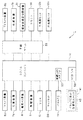
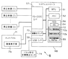
図1ないし図6は本発明の実施例1に係り、図1は本発明の実施例1の医療用内視鏡システムの全体構成を示し、図2は図1の構成の主要部をブロック図で示し、図3はパネルPCが着脱自在に取り付けられるトロリなどを示し、図4はシステムコントローラ及びパネルPCの内部構成を示し、図5はセンサの検出結果により表示用GUIと操作用GUIとが切り替えられて表示されるパネルPCでの画像表示例を示し、図6は表示画面切替制御の動作説明のフローチャートを示す。
図1に示すように本発明の医療用システム、より具体的には医療用内視鏡システム1は、手術台2に横たわる患者3の両側には第1のトロリ4及び第2のトロリ5とが配置され、これらの両トロリ4、5には観察、検査、処置、記録等を行う複数の医療装置(内視鏡周辺機器)が搭載されている。
1 to 6 relate to the first embodiment of the present invention, FIG. 1 shows the overall configuration of the medical endoscope system according to the first embodiment of the present invention, and FIG. 2 is a block diagram showing the main part of the configuration of FIG. 3 shows a trolley on which the panel PC can be detachably attached, FIG. 4 shows the internal configuration of the system controller and the panel PC, and FIG. 5 shows the display GUI and the operation GUI depending on the detection result of the sensor. An example of image display on the panel PC displayed by switching is shown, and FIG. 6 is a flowchart for explaining the operation of the display screen switching control.
As shown in FIG. 1, the medical system of the present invention, more specifically, the
本実施例では、第1のトロリ4にはTVカメラ装置(或いはカメラコントロールユニット)6a、光源装置7a、高周波焼灼装置(以下、電気メス装置)8、気腹装置9、VTR10、第1の内視鏡モニタ12a、これら複数の医療装置の状態を表示する集中表示パネル機能とこれら複数の医療装置に対する操作入力を集中して行う集中操作パネル機能とを兼ねるパネル型コンピュータ(パネルPCと略記)13、これらの医療装置を集中制御するシステムコントローラ14等が搭載されている。パネルPC13を除く各医療装置は、図示しないケーブルを介してシステムコントローラ14と接続され、双方向通信が可能になっている。
また、光源装置7aは、照明光を伝送するライトガイドケーブル15aを介して内視鏡16aに接続され、光源装置7aの照明光を内視鏡16a(のライトガイド)に供給し、この内視鏡16aの挿入部が刺入された患者3の腹部内の患部等を照明する。
In the present embodiment, the
The light source device 7a is connected to the endoscope 16a via a light guide cable 15a that transmits illumination light, and supplies the illumination light of the light source device 7a to the endoscope 16a (light guide thereof). The affected part in the abdomen of the patient 3 into which the insertion part of the mirror 16a is inserted is illuminated.
この内視鏡16aの接眼部には撮像素子を備えたカメラヘッド18aが装着され、内視鏡16aの観察光学系による患部等の光学像をカメラヘッド18a内の撮像素子で撮像し、カメラケーブル19aを介してTVカメラ装置6aに伝送し、TVカメラ装置6a内の信号処理回路で信号処理して、映像信号を生成し、内視鏡モニタ12aに出力して患部等の内視鏡画像を表示できるようにしている。
また、気腹装置9には例えば炭酸ガスボンベ(以下、ガスボンベと略記)20が接続され、このガスボンベに接続された気腹装置9から患者3に延びた気腹チューブ21を介して患者3の腹腔内に炭酸ガスを供給できるようにしている。この場合、気腹チューブ21は、患者3の腹部に刺入されるガイド管22を介して、その腹腔内に炭酸ガスを供給する。
A camera head 18a equipped with an image sensor is attached to the eyepiece of the endoscope 16a, and an optical image of the affected part or the like by the observation optical system of the endoscope 16a is captured by the image sensor in the camera head 18a. The video signal is transmitted to the
Further, for example, a carbon dioxide gas cylinder (hereinafter abbreviated as a gas cylinder) 20 is connected to the
また、電気メス装置8は、ガイド管22を介して腹腔内に挿入される処置具23とケーブル24を介して接続されると共に、患者3の背面側に広い面積で当接する患者プレート25ともリターンケーブル26で接続される。
なお、内視鏡16aは、手術台2の側面に取り付けた内視鏡用ホルダ27により保持されている。
また、システムコントローラ14には、マイクセット28が接続され、術者はマイクセット28を装着して、音声によりシステムコントローラ14に指示入力などを行うことができるようにしている。
また、第2のトロリ5には、医療装置として内視鏡用TVカメラ装置6b、光源装置7b、超音波凝固切開装置31、ビデオプリンタ32、第2の内視鏡モニタ12b、中継ユニット33等が搭載され、それぞれの装置は図示しないケーブルで中継ユニット33に接続され、双方向の通信を可能としている。
The
The endoscope 16 a is held by an
In addition, a
Further, the
光源装置7bは、照明光を伝送するライトガイドケーブル15b介して内視鏡16bに接続され、光源装置7bの照明光を内視鏡16b(のライトガイド)に供給し、この内視鏡16bの挿入部が刺入された患者3の腹部内の患部等を照明する。
この内視鏡16bの接眼部には撮像素子を備えたカメラヘッド18bが装着され、内視鏡16bの観察光学系による患部等の光学像をカメラヘッド18b内の撮像素子で撮像し、カメラケーブル19bを介してTVカメラ装置6bに伝送し、TVカメラ装置6b内の信号処理回路で信号処理して、映像信号を生成し、内視鏡モニタ12bに出力して患部等の内視鏡画像を表示できるようにしている。
The
A
また、超音波凝固切開装置31は、ケーブル34を介して処置具23と接続され、超音波凝固切開装置31から処置具23に設けた超音波振動子を駆動して、超音波による凝固或いは切開を行うことができるようにしている。この処置具は、上記電気メス装置8からの高周波信号により、電気メスとして処置を行うこともできる。
また、中継ユニット33は、システムコントローラ14とケーブル35で接続されており、双方向の通信を可能にしている。
また、中継ユニット33にはリモートコトローラ(リモコンと略記)36が接続され、術者は、このリモコン36を滅菌域から操作することにより、中継ユニット33を介してシステムコントローラ14にその操作信号を伝送することができる。そして、システムコントローラ14からその操作に対応して、各種の装置をリモート制御を行えるようにしている。
Further, the ultrasonic coagulation /
In addition, the
Further, a remote controller (abbreviated as “remote control”) 36 is connected to the
また、トロリ4には、パネルPC13を着脱自在に取付可能とするパネルPC取付マウント41が設けてある。
図2は、図1に示した医療用内視鏡システム1におけるシステムコントローラ14及びシステムコントローラ14に接続される機器の構成をブロック図で示している。TVカメラ装置6a、6b、光源装置7a、7b、電気メス装置8、気腹装置9、VTR10、内視鏡モニタ12a、12b、音声入力を行うマイクセット28、超音波凝固切開装置31、リモコン36は、例えばRS232Cのシリアルインタフェースでシステムコントローラ14に、或いは中継ユニット33を介して接続され、それらを制御できるようにしている。
The
FIG. 2 is a block diagram showing a configuration of the
また、TVカメラ装置6a、6b、VTR10、内視鏡モニタ12a、12bは、図示しない映像ケーブル等を介してシステムコントローラ14に、或いは中継ユニット33を介して接続され、TVカメラ装置6a、6bにより生成した映像信号をVTR10、内視鏡モニタ12a、12bに出力できるようにしている。
また、本実施例においては、図3(A)に示すようにトロリ4における例えば上面から突出したアーム42には平板状のパネルPC取付マウント41が設けてある。このパネルPC取付マウント41における例えばその中央位置には、このパネルPC取付マウント41の中央位置にパネルPC13が取り付けられているか否かを検出するパネルPC取付検出センサ43が設けてあり、その周囲の複数箇所にパネルPC13を固定するパネルPC取付用ネジ穴44が設けてある。
The
In this embodiment, as shown in FIG. 3A, a flat panel
このパネルPC取付マウント41には、その上部側に示すパネルPC13を着脱自在に取り付けられるようにしている。また、パネルPC取付マウント41にパネルPC13を取り付けた状態をその右側の図3(B)に示している。なお、図3(B)においては、パネルPC取付マウント41周辺部以外は、図3(A)と同じであるため、省略している。 なお、パネルPC取付検出センサ43は、後述する金属センサ等を用いて構成されている。勿論、金属センサに限らず、例えばマイクロスイッチ等により構成して、パネルPC取付マウント41にパネルPC13が取り付けられた際に、そのパネルPC13の裏面による押圧でマイクロスイッチがOFFからONになることにより、パネルPC13が所定位置に取り付けられたか否かの検出信号が出力されるようにしても良い。
A
図4は、システムコントローラ14及びパネルPC13周辺部の構成の詳細を示す。 システムコントローラ14は、システム全体の集中制御処理を行う中央演算処理装置としてのMPU51と、このMPU51のワークエリアやデータの一時記憶等に利用されるメモリ52と、無線LANを構成する無線LANアダプタ53と、オペレーティングシシテム(OSと略記)54及び周辺装置制御プログラム55等を格納するためのハードディスク(HDDと略記)56と、周辺装置(1)、(2)、…と双方向の通信を行う例えばシリアル通信手段としてのRS−232C インタフェース(I/F)57と、パネルPC取付検出センサ43と双方向の通信を行う例えばシリアル通信手段としてのUSB I/F58とを備え、これらはバスにより接続されている。
FIG. 4 shows details of the configuration of the
なお、周辺装置(1)、(2)、…は、図2のTVカメラ装置6a等を表わしている。 また、パネルPC13は、携帯ないしは把持して操作がし易いパネル型コンピュータにより構成されている。このパネルPC13は、このパネルPC13各部を制御するMPU61と、このMPU61のワークエリアやデータの一時記憶等に利用されるメモリ62と、無線LANを構成する無線LANアダプタ63と、オペレーティングシシテム(OSと略記)64及び制御プログラム65等を格納するためのハードディスク(HDDと略記)66と、画像等を表示する機能とユーザによるタッチ操作を検出する機能とを有する画像表示部&タッチセンサ部67とを有し、これらはバスにより接続されている。
The peripheral devices (1), (2),... Represent the
なお、画像表示部&タッチセンサ部67は、例えば画像表示部としての液晶ディスプレイ(LCDと略記)と、このLCDの表示面にタッチ操作とそのタッチ操作位置を検出するタッチセンサパネルとが設けられたものである。
また、制御プログラム65内には、表示用グラフィカルユーザインタフェース(GUIと略記)情報と操作用GUI情報とを格納(記録)したGUI情報格納部(図4ではGUI情報格納と略記)65aと、このGUI情報格納部65aに格納された表示用GUI情報と操作用GUI情報との一方を読み出して画像表示部&タッチセンサ部67(の画像表示部)に表示することにより、画像表示部&タッチセンサ部67の表示画面を切り替える画面切替処理機能(図4では画面切替処理と略記、以下他の図7等でも流用)65bとを有する。
The image display unit &
Further, in the
MPU61は、制御プログラム65に従って制御操作を行い、GUI情報格納部65aから表示用GUIと操作用GUIの一方の情報を読み出し、読み出した一方の情報を画像表示部&タッチセンサ部67(の画像表示部)に切り替えて表示する表示画面切替制御を行う。
なお、表示用GUIと操作用GUIの情報をメモリ62に格納(記録)しておき、このメモリ62から表示する表示用GUI或いは操作用GUIの情報を読み出すアドレスを切り替えて表示画面切替制御を行うようにしても良い。
パネルPC13及びシステムコントローラ14は、動作状態においては、無線LANにより双方向で無線通信を行う。また、システムコントローラ14は、パネルPC取付検出センサ42によるパネルPC取付の検出信号により、パネルPC13の表示内容を切り替える制御信号を無線LANを介してパネルPC13に送信する。
The
The display GUI and the operation GUI information are stored (recorded) in the
The
そして、パネルPC13は制御信号に対応して画像表示部&タッチセンサ部67(の画像表示部)に切り替えて表示する表示画面切替制御を行う。
この場合、システムコントローラ14は、パネルPC取付が検出されない場合には、操作パネルとして操作し易い表示内容を表示させ、パネルPC取付検出信号が検出された場合には表示パネルの表示内容を表示させる制御信号をパネルPC13に送る。
従って、パネルPC13は、パネルPC取付検出信号により、このパネルPC13における画像表示部&タッチセンサ部67の表示内容を変更すると共に、タッチ操作に対する制御内容を変更する。
具体的には、パネルPC取付検出信号の検出結果に応じて、図5に示すように画像表示部&タッチセンサ部67(画像表示部)の表示内容として、表示用GUIと操作用GUIを切り替えて表示する。
The
In this case, the
Accordingly, the
Specifically, according to the detection result of the panel PC attachment detection signal, the display GUI and the operation GUI are switched as display contents of the image display unit & touch sensor unit 67 (image display unit) as shown in FIG. To display.
パネルPC取付検出センサ43が設けられた所定位置、本実施例ではパネルPC取付マウント41の位置にパネルPC13が取り付けられていない場合には、図5の右側に示す操作用GUIの表示画面Daとなり、パネルPC取付マウント41に取り付けられた場合には、図5の左側に示す表示用GUIの表示画面Dbとなる。換言すると、パネルPC取付検出センサ43が設けられた所定位置からパネルPCの位置が取り外されて移動されると、パネルPC13の表示内容が変更される。
図5の右側の操作用GUIの表示画面Daの場合には、看護師などがこのパネルPC13を携帯して、周辺装置の操作や設定を行い易いように、周辺装置(具体例では気腹装置、VTRなど)の表示とその周辺装置の動作のON/OFFを行う操作用ボタン、周辺装置(具体例では電気メス)の動作モードの切替用ボタン、周辺装置の出力を変更する出力Up/Downボタンが表示されるようにしている。
When the
In the case of the operation GUI display screen Da on the right side of FIG. 5, a peripheral device (in the specific example, a pneumoperitoneum device) is provided so that a nurse or the like can carry the
また、複数の表示内容を選択するメニュー、設定を行うセットアップ、マニュアルで表示用GUI(表示パネルとも言う)に切り替える表示画面切替のボタンも表示している。 一方、パネルPC取付マウント41に取り付けられた場合に表示される左側の表示用GUIの表示画面Dbにおいては、周辺装置における設定状態、出力値等と、VTR10等の画像記録装置にキャプチャーしている画像を表示する。術者は、これを見ることにより、周辺装置の設定状態を把握することができる。
また、複数の表示内容を選択するメニュー、設定を行うセットアップ、マニュアルで操作用GUI(操作パネルとも言う)に切り替える表示画面切替のボタンも表示している。 このような構成における本実施例の動作を以下に説明する。
患者3に対して内視鏡下の外科手術を行う場合、看護師は、図1に示すようにトロリ4及び5に、TVカメラ装置6a等、この外科手術に使用する周辺装置を搭載する。
In addition, a menu for selecting a plurality of display contents, a setup for setting, and a display screen switching button for manually switching to a display GUI (also referred to as a display panel) are also displayed. On the other hand, the display screen Db of the left display GUI that is displayed when mounted on the panel
A menu for selecting a plurality of display contents, a setup for setting, and a display screen switching button for manually switching to an operation GUI (also referred to as an operation panel) are also displayed. The operation of this embodiment in such a configuration will be described below.
When performing an endoscopic surgical operation on the patient 3, the nurse mounts peripheral devices used for this surgical operation, such as a
また、TVカメラ装置6aに内視鏡16aを接続などして内視鏡検査を行えるようにすると共に、処置を行う処置具23もこれに対応する周辺装置に接続する。そして、医療用内視鏡システム1の電源を投入し、看護師等は、使用する周辺装置の設定を行う。
電源が投入されると、システムコントローラ14は、接続された周辺装置を認識して周辺装置の動作を集中制御する状態になる。また、システムコントローラ14は、無線LANを介してパネルPC13を制御する状態になる。
この場合、システムコントローラ14は、パネルPC取付検出センサ43の検出信号を監視して、パネルPC13の画像表示部&タッチセンサ部67での表示画面切替を制御する動作を行う。この切替制御の動作を図6に示す。
Further, the endoscope 16a is connected to the
When the power is turned on, the
In this case, the
最初のステップS1においてシステムコントローラ14のMPU51は、パネルPC取付検出センサ43の検出信号をモニタしてパネルPC13がパネルPC取付検出センサ43の所定位置に取り付けられているかの判定を行う。
そして、MPU51は、取り付けられていないと判定した場合にはステップS2に進み、取り付けられていると判定した場合にはステップS5に進む。ステップS2においてMPU51は、パネルPC13のMPU61に操作用GUIを表示させる制御信号を無線で送る。MPU61は、この制御信号を受けてGUI情報格納部65aから操作用GUIの情報を読み出す。
そして、次のステップS3においてこのMPU61は、ステップS2で読み出した操作用GUIの情報を画像表示部&タッチセンサ部67で表示する制御を行う。つまり、画像表示部&タッチセンサ部67の画像表示部には、操作用GUIが表示された図5の左側に示すような表示画面Daとなる。
In the first step S <b> 1, the
The
In the next step S3, the
周辺装置の初期設定等の操作を行う場合には、看護師等は、パネルPC13を把持して操作を行う。この場合、パネルPC13は、上記の処理により自動的に操作用GUIの表示画面Daとなっているので操作性が良い。
ステップS3の処理の後、次のステップS4においてシステムコントローラ14のMPU51は、(ステップS1と同様に)パネルPC取付検出センサ43の検出信号をモニタしてパネルPC13がパネルPC取付検出センサ43の位置に取り付けられているかの判定を行う。
そして、MPU51は、取り付けられていない、つまり取り付けられていない状態のままで変化しないと判定した場合には、操作用GUIを表示した状態のままステップS4の処理を繰り返し行い、取り付けられている(つまり取り付けられていない状態から取り付けられた状態に変化した)と判定した場合にはステップS5に移る。
When performing operations such as initial setting of peripheral devices, a nurse or the like holds the
After the process of step S3, in the next step S4, the
If it is determined that the
周辺装置の初期設定等の操作を終了した場合、看護師等は、設定操作していたパネルPC13をパネルPC取付マウント41に取り付ける。すると、このパネルPC13の取付がパネルPC取付検出センサ43により検出され、パネルPC取付検出センサ43は検出信号をMPU51に送り、MPU51は、ステップS5の処理を行う。
ステップS5においてMPU51は、パネルPC取付検出センサ43からの検出信号により、パネルPC13のMPU61に対して表示用GUIを表示させる制御信号を無線で送る。
MPU61は、この制御信号を受けてGUI情報格納部65aから表示用GUIの情報を読み出す。そして次のステップS6においてMPU61は、画像表示部&タッチセンサ部67に表示用GUIの情報を表示する制御を行う。つまり、画像表示部&タッチセンサ部67の画像表示部には、図5の左側に示す表示用GUIが表示される表示画面Dbとなる。これにより、術者は周辺装置の設定状態を把握することができる。
When the operation such as the initial setting of the peripheral device is completed, the nurse or the like attaches the
In step S <b> 5, the
In response to this control signal, the
このように、パネルPC13をパネルPC取付マウント41に取り付けることにより、自動的に表示用GUIの表示画面Dbに切り替えられるので、看護師等は切替操作を行わなくても済み、操作性が良い。
ステップS6の処理が行われた後、次のステップS7においてシステムコントローラ14のMPU51は、(ステップS1と同様に)パネルPC取付検出センサ43の検出信号をモニタしてパネルPC13がパネルPC取付検出センサ43の位置に取り付けられているかの判定を行う。
そして、MPU51は、取り付けられていない、つまり取り外されたと判定した場合にはステップS2に戻り、取り付けられていると判定した場合にはこのステップS7の処理を継続する。
Thus, by attaching the
After the process of step S6 is performed, in the next step S7, the
The
このように動作する本実施例によれば、1つのパネルPC13を用いて表示パネルの機能と操作パネルの機能を切り替えて使用できる構成にすると共に、表示パネルとして表示させるのに適した所定位置にパネルPC13があるか否か、或いはこの所定位置から取り外されて移動されているか否かを検出することにより、表示用GUIと操作用GUIとを切り替えて表示するようにしているので、操作性を確保して、かつ狭い設置スペースでも使用(対応)できる。
また、1つのパネルPC13を兼用しているので、2つを用いる場合よりもコストを削減することができる。また、表示パネルと操作パネルとを両方設置していた従来例の場合よりも、空きスペースが確保できるため、術者に与えていた圧迫感を軽減できる。
According to this embodiment that operates as described above, the structure of the display panel and the function of the operation panel can be switched using one
Further, since one
次に図7から図10を参照して本発明の実施例2を説明する。実施例1においては、パネルPC13を用いてその表示画面の表示内容を切り替える構成にしていたが、本実施例においては実施例1における画像表示部&タッチセンサ部67の構成に相当するタッチパネル71を用いる。
本実施例は、図1に示す医療用内視鏡システム1において、システムコントローラ14と一部構成が異なるシステムコントローラ14BとパネルPC13の代わりにタッチパネル71が採用された構成である。
図7は本実施例の医療用内視鏡システム1Bにおけるシステムコントローラ14B及びタッチパネル71の内部構成を示す。
Next, a second embodiment of the present invention will be described with reference to FIGS. In the first embodiment, the display content of the display screen is switched using the
In this embodiment, in the
FIG. 7 shows the internal configuration of the
本実施例におけるシステムコントローラ14Bは、図4に示したシステムコントローラ14において、例えばハードディスク56内には、さらにタッチパネル制御プログラム72を設けている。このタッチパネル制御プログラム72は、表示用GUIと操作用GUIとを含むGUI情報格納部72aと、タッチパネル71の表示画面を切り替える画面切替処理機能72bとを有する。
また、本実施例では、システムコントローラ14Bには、タッチパネル71における画像表示部71aに表示用GUI及び操作用GUIの情報を出力する画像出力I/F73が設けてある。また、このシステムコントローラ14BにおけるRS−232C I/F57には、周辺装置(1)、周辺装置(2)、…、周辺装置(n)と共に、タッチパネル71も接続されている。そして、タッチパネル71(のタッチセンサ部)を操作した場合には、その操作信号がMPU51に送られ、MPU51は対応する制御動作を行う。
The
In the present embodiment, the
また、USBI/F58には、パネル取付位置検出センサ74が接続されており、このパネル取付位置検出センサ74により検出された検出信号は、MPU51に入力される。そして、このMPU51は、この検出信号に応じて、タッチパネル71の画像表示部71aにおける表示内容を切り替える制御を行う。
本実施例におけるタッチパネル71は、図8(A)、図8(B)に示すように、トロリ4から上方に突出するように設けたアーム75に沿ってスライド自在に固定される構造にしている。なお、図8(A)はトロリ4の正面側から見た正面図を示し、図8(B)は側面側から見た側面図を示す。
図8(B)及びその拡大図に示すようにこのタッチパネル71における背面側の取付部材76には、アーム75をスライド自在に通す孔部77と、固定ねじ78を設けてアーム75における任意の高さ位置に固定できるようにしている。また、この取付部材76にはチルト機構79を設けてそのノブ79aを操作することにより、タッチパネル71の表示面を傾けることができるようにしている。
Further, a panel mounting
As shown in FIGS. 8A and 8B, the
As shown in FIG. 8B and its enlarged view, the
また、パネル取付位置検出センサ74は、アーム75における表示パネルとして表示するのに適した高さ位置、この例ではアーム42の上端に固定されている。このパネル取付位置検出センサ74は、例えば金属センサにより構成され、この金属センサは拡大図に示すように取付部材76に突出するように設けた金属製の検出片76aの有無を検出して、タッチパネル71が、表示パネルとして使用される所定の高さ位置に設定されているか否かを検出する。
そして、図8(A)、図8(B)の実線で示す位置にタッチパネル71が設定されていると、パネル取付位置検出センサ74の検出信号により、システムコントローラ14BのMPU51は、表示用GUIを表示するように制御を行う。また、2点鎖線で示すようにタッチパネル71が下側に移動されて、この検出信号が出力されていない場合には、システムコントローラ14BのMPU51は操作用GUIを表示するように制御を行う。
Further, the panel mounting
When the
なお、ここでは、タッチセンサ71が表示パネルとして使用する高さの位置に設定されているか否かを検出する1つのパネル取付位置検出センサ74のみとしているが、さらに操作パネルとして操作するのに適した高さ位置、具体的にはアーム75の上端よりは下方側の高さ位置に、第2のパネル取付位置検出センサを設けるようにしても良い。そして、両センサの検出信号で表示画面切替を行う構成にしても良い。
本実施例におけるタッチパネル71の画像表示部71aで表示する表示用GUIと操作用GUIの表示例を図9に示す。図9に示す表示例は、例えば図5と同じ表示例で示している。
実施例1においてはシステムコントローラ14の制御信号により、パネルPC13側で表示する表示用GUIと操作用GUIを切り替える制御動作を行っていたが、本実施例ではシステムコントローラ14Bにより、タッチパネル71の画像表示部71aで表示する表示用GUIと操作用GUIを切り替える制御動作を行うようにしている。
Here, only one panel mounting
A display example of the display GUI and the operation GUI displayed on the image display unit 71a of the
In the first embodiment, the control operation for switching between the display GUI and the operation GUI displayed on the
その他の構成は実施例1と同様である。
次に本実施例における画面切替の制御動作を説明する。
タッチパネルの表示画面切替制御の動作がスタートすると、最初のステップS11においてMPU51は、パネル取付位置検出センサ74の検出信号によりタッチパネル71が所定位置としての表示用位置に設定されているか否かの判定を行う。
そして、タッチパネル71が表示用位置に設定されていないと、次のステップS12においてMPU51は、操作用GUIの情報をGUI情報格納部72aから読み出す。そして、次のステップS13においてMPU51は、操作用GUIをタッチパネル71の画像表示部71aで表示させる。
Other configurations are the same as those of the first embodiment.
Next, the screen switching control operation in this embodiment will be described.
When the operation of the display screen switching control of the touch panel is started, in the first step S11, the
If the
その後、次のステップS14においてMPU51は、ステップS11の判定処理と同様にパネル取付位置検出センサ74の検出信号によりタッチパネル71が表示用位置に設定されているか否かの判定を行う。そして、タッチパネル71が表示用位置に設定されていないと、このステップS14の処理を繰り返し行う。
一方、タッチパネル71が表示用位置に設定されていると判定した場合にはステップS15に進む。
このステップS15においてMPU51は、表示用GUIの情報をGUI情報格納部72aから読み出す。そして、次のステップS16においてMPU51は、表示用GUIをタッチパネル71の画像表示部71aで表示させる。その後、次のステップS17においてMPU51は、ステップS11の判定処理と同様にパネル取付位置検出センサ74の検出信号によりタッチパネル71が表示用位置に設定されているか否かの判定を行う。
Thereafter, in the next step S14, the
On the other hand, when it determines with the
In step S15, the
そして、タッチパネル71が表示用位置に設定されていると、このステップS17の処理を繰り返し行う。
一方、タッチパネル71が表示用位置に設定されていないと判定した場合にはステップS12に戻る。
このような動作を行う本実施例によれば、実施例1の場合と類似して共通のパッチパネル71により、表示パネルの表示機能と操作パネルの表示及び操作機能を切り替えて表示するようにしているので、コストを削減できると共に、狭い設置スペースでも使用できるようになる。
また、実施例1におけるパネルPC13の代わりにタッチパネル71で兼用するようにしているので、よりコスト削減が可能となる。その他、実施例1とほぼ同様の効果を有する。
次に本実施例の変形例を説明する。図11は変形例におけるシステムコントローラ14C及びタッチパネル71の構成を示す。
If the
On the other hand, when it determines with the
According to the present embodiment performing such an operation, the display function of the display panel and the display and operation functions of the operation panel are switched and displayed by the
Further, since the
Next, a modification of this embodiment will be described. FIG. 11 shows the configuration of the
本変形例においては、実施例2のシステムコントローラ14Bにおいて、ハードディスク56におけるタッチパネル制御プログラム72内に、さらにタイマ処理機能72cを設け、パネル取付位置検出センサ74により画面切替を行う機能を無効とする選択を行った場合には、タイマー処理機能72cにより表示画面の切替制御を行うことができるようにしている。
その他の構成は実施例2と同様である。本変形例による動作を図12を参照して説明する。
画面切替制御がスタートすると、最初のステップS21においてMPU51は、パネル取付位置検出センサ74による検出信号で画面切替制御を行う機能を無効にするか否かの判定を行う。術者等のユーザは、都合の良い方を選択することができる。
In this modification, in the
Other configurations are the same as those of the second embodiment. The operation according to this modification will be described with reference to FIG.
When the screen switching control is started, in the first step S21, the
そして、このパネル取付位置検出センサ74による検出信号で画面切替制御を行う場合にはステップS22の処理に進み、この検出信号で画面切替制御を行うことを無効にした場合にはステップS23に移る。ステップS22においては、図10で説明したステップS11からステップS16の処理を行う。このため、ステップS22の処理の説明は省略する。
一方、ステップS23においてMPU51は、ハードディスク56に格納されたGUI情報から表示用GUIの情報を読み出し、タッチパネル71の画像表示部71aに表示用GUIを表示する。そして、次のステップS24においてMPU51は、タッチパネル71からのタッチ入力の有無を判定する。タッチ入力が無い場合には、この処理を継続して行い、タッチ入力があると判定した場合には、次のステップS25においてMPU25は、タイマー処理機能72cによりタイマーの計時動作をスタートさせる。
When the screen switching control is performed using the detection signal from the panel mounting
On the other hand, in step S <b> 23, the
また、MPU25はステップS26に示すようにハードディスク56に格納されたGUI情報から操作用GUIの情報を読み出し、タッチパネル71の画像表示部71aに操作用GUIを表示する。
また、次のステップS27においてMPU51は、タッチパネル71からのタッチ入力の有無を判定する。タッチ入力がある場合には、ステップS25に戻り、タイマーの計時動作をスタートさせる。なお、このタイミング以前にタイマーの計時動作がスタートしている場合には、MPU51はリセットして計時動作をスタートさせる。
ステップS27においてMPU51は、タッチ入力が無いと判定した場合には、次のステップS28において、タイマーによる計時動作で一定時間が経過したか否かの判定を行う。
Further, the
In the next step S <b> 27, the
If it is determined in step S27 that there is no touch input, the
そして、まだ一定時間経過していない場合には、ステップS27に戻り、操作用GUIの表示画面の状態でステップS27の処理を行う。一方、一定時間経過している場合には、ステップS23に戻り、タッチパネル71の画像表示部71aに表示用GUIを表示する。
本変形例によれば、術者等は外科手術等を行う場合、タッチパネル71による表示画面を切り替える制御を行う場合の選択肢が広がるので、操作性或いは使い勝手がより向上する。その他は実施例2と同様の効果を有する。
If the fixed time has not yet elapsed, the process returns to step S27, and the process of step S27 is performed in the state of the display screen of the operation GUI. On the other hand, if the predetermined time has elapsed, the process returns to step S23, and the display GUI is displayed on the image display unit 71a of the
According to this modified example, when the surgeon or the like performs a surgical operation or the like, options for performing a control for switching the display screen by the
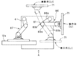
次に図13から図15を参照して本発明の実施例3を説明する。本実施例は、タッチパネル71の表示面の方向を検出して、表示画面の切替制御を行うようにしたものである。 本実施例の医療用内視鏡システム1Dにおけるシステムコントローラ14D及びタッチパネル71の周辺部の構成を図13に示す。
図13に示すようにタッチパネル71には、このタッチパネル71を回転駆動するモータ駆動部81と、このモータ駆動部81(のモータ81a)を制御するモータ制御部82が設けてある。
また、このタッチパネル71には、その表示面の表示方向を、複数の角度位置における検出信号で検出する角度位置検出センサ83が設けてある。
また、本実施例では術者等が音声入力するマイク84が設けてあり、このマイク84による音声入力に対する信号処理を行うサウンドカード85が、システムコントローラ14Dに設けてある。
Next, Embodiment 3 of the present invention will be described with reference to FIGS. In the present embodiment, the direction of the display surface of the
As shown in FIG. 13, the
In addition, the
Further, in this embodiment, a
また、このシステムコントローラ14Dは、図7に示すシステムコントローラ14Bにおいてハードディスク56内に設けたタッチパネル制御プログラム72に、サウンドカード85で信号処理された音声に基づき、モータ駆動部81のモータ81aを回転駆動させる音声制御機能72dと、この音声制御機能72dによりモータ81aの回転制御を行う回転制御機能72eとを設けている。
また、本実施例では、GUI情報格納部72aは、上述した表示用GUIと操作用GUIの情報の他に、さらに麻酔を担う麻酔医が観察する場合に適切なGUI情報となる麻酔用GUIの情報も格納している。
なお、上記モータ制御部82はRS−232C I/F57に接続されている。図14は、トロリ4の上面に設けたタッチパネル保持機構86を示す。
The
In addition, in this embodiment, the GUI
The
トロリ4の上面には内視鏡モニタ12aを保持するアーム機構87と、タッチパネル71の表示方向を変更可能に保持するタッチパネル保持機構86とが設けてある。
このタッチパネル保持機構86は、トロリ4の上面に一端が連結される第1のアーム88aと、この第1のアーム88aの他端にその一端が回動自在に連結され、その他端にタッチパネル71が取り付けられる第2のアーム88bとを有し、第1のアーム88aと第2のアームの連結部にモータ駆動部81を構成するモータ81aが設けてある。
そして、このモータ81aを回転駆動することにより、この図14に示すように第1のアーム88aの他端を回転中心として第2のアーム88bを回転して、タッチパネル71の表示面の方向を変更できるようにしている。
On the upper surface of the
The touch
Then, by rotating the motor 81a, the
また、第1のアーム88aと第2のアーム88bとの連結部付近における回転方向の2箇所には、図13で示した角度位置検出センサ83を構成する2つの第1及び第2センサ83a、83bと、これら第1及び第2センサ83a、83bにより検出される2つの検出片89a、89bが設けてある。なお、両センサ83a、83bは、例えば金属で構成された検出片89a、89bを検出する金属センサで構成される。
図15は図14における矢視A方向からタッチパネル保持機構86を見た側面図の概略を示す。なお、図14における矢視A方向と反対側(紙面の下側)に手術台が配置される。
従って、手術台側の術者は、矢視A方向に対向する状態のタッチパネル71の表示面を見た場合、つまり図14の2点鎖線で示す状態が、観察し易い状態となる。そして、以下に説明するようにタッチパネル71の表示面がこの方向を向いていると検出した場合には、MPU51は表示用GUIを表示するように制御する。
In addition, two first and second sensors 83a constituting the angular
15 schematically shows a side view of the touch
Accordingly, when the operator on the operating table side looks at the display surface of the
また、看護師は、図14におけるトロリ4の右側にて周辺装置の設定操作を行う場合が多く、これに対応して、図14の実線で示すようにタッチパネル71の表示面が右側に対向する方向を向いていると検出した場合には、操作用GUIを表示するように制御する。 また、麻酔医は、図14におけるトロリ4の位置の上側となる位置にて周辺装置の設定状態を観察して麻酔の処置を担う場合が多く、これに対応して、図14の2点鎖線で示すようにタッチパネル71の表示面がこの方向に対向する方向を向いていると検出した場合には、麻酔用GUIを表示するように制御する。
図15に示すように第1のアーム88aと第2のアーム88bの連結部には第1のアーム88aに固定されたモータ制御部82と、モータ駆動部81におけるステータ部分とが固定され、その上部にモータ駆動部81におけるステータ部分となる周方向の2箇所に第1及び第2センサ83a、83bが設けられている。また、モータ81a(のロータ)側における周方向の2箇所には、第1及び第2センサ83a、83bにより検出される検出片89a、89bが取り付けられている。
Further, the nurse often performs the peripheral device setting operation on the right side of the
As shown in FIG. 15, a
図15に示すように第1センサ83aには検出片89aが、第2センサ83bには検出片89bが近接して対向する状態の場合には、各センサ83a、83bはそれぞれ検出信号をMPU51に出力する。この場合には、MPU51は、タッチパネル71の表示面に操作用GUIを表示する制御を行う。
また、図15の状態において、モータ81aが例えば符号B側に回転されると、第2センサ83bが検出片89aを検出するのみの状態になる。この場合には、MPU51は、タッチパネル71の表示面に表示用GUIを表示する制御を行う。
また、図15の状態において、モータ81aが例えば符号Bと反対側に回転(逆転)されると、第1センサ83aが検出片89bのみを検出する状態になる。この場合には、MPU51は、タッチパネル71の表示面に麻酔用GUIを表示する制御を行う。
As shown in FIG. 15, when the detection piece 89a is in close proximity to the first sensor 83a and the
Further, in the state of FIG. 15, when the motor 81a is rotated, for example, to the sign B side, the
Further, in the state of FIG. 15, when the motor 81a is rotated (reversely rotated) to the opposite side to the symbol B, for example, the first sensor 83a detects only the
本実施例では、モータ81aの回転をマイク84からの音声入力により制御することができるようにしている。
このような構成による本実施例における画面表示切替の動作を以下に説明する。
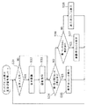
この動作が開始すると、最初のステップS31においてMPU51は、マイク84からサウンドカード85を介しての音声入力ありか否かを判定する。音声入力ありと判定した場合には、次のステップS32においてMPU51は、音声制御機能72dにより、いずれの向きに回転させるコマンドか、或いは回転状態の場合その回転を停止させるコマンドか等の音声認識を行う。
そして、音声認識結果に基づいて、次のステップS33においてMPU51は、回転制御機能72eにより、モータ81aを正転或いは逆転するように回転駆動させたり、回転駆動していた場合にその回転を停止させる制御を行い、次のステップS34に進む。
In the present embodiment, the rotation of the motor 81a can be controlled by voice input from the
The screen display switching operation in the present embodiment having such a configuration will be described below.
When this operation starts, the
Based on the voice recognition result, in the next step S33, the
一方、ステップS31において、音声入力なしと判定した場合にはステップS34に移る。このステップS34においてMPU51は、第1センサ83a及び第2センサ83bの検出ありか否かを判定する。
そして、両センサ83a、83bの検出信号がある場合には、ステップS35に示すようにMPU51は、タッチパネル71の表示面に操作用GUIを表示する制御を行い、その後ステップS31に戻る。
一方、ステップS34において両センサ83a、83bの検出信号が無い場合には、ステップS36においてMPU51は、第1センサ83aのみの検出ありか否かの判定を行う。そして、第1センサ83aのみの検出ありと判定した場合には、ステップS37に示すようにMPU51は、タッチパネル71の表示面に麻酔用GUIを表示する制御を行い、その後ステップS31に戻る。
On the other hand, if it is determined in step S31 that there is no voice input, the process proceeds to step S34. In step S34, the
If there is a detection signal from both the
On the other hand, if there is no detection signal from both
一方、ステップS36において第1センサ83aのみの検出信号が無いと判定した場合には、ステップS38においてMPU51は、第2センサ83bのみの検出状態と判定して、タッチパネル71の表示面に表示用GUIを表示する制御を行い、その後ステップS31に戻る。そして、上述した処理を繰り返す。
このように動作する本実施例によれば、音声に基づいてモータ81aによりタッチパネル71を回転制御し、その際タッチパネル71が所定の回転角度位置に設定された場合には、センサ83a、83bによりその回転角度位置を検出して、その回転角度位置の場合に適した表示画面に切り替えるようにしているので、コストを削減して、狭い設置スペースで使用できると共に、操作性を大幅に向上することができる。
また、本実施例においては、3つの表示画面を切り替えて表示することができるようにしているので、コストも大幅に削減することができる。
On the other hand, if it is determined in step S36 that there is no detection signal for only the first sensor 83a, the
According to this embodiment that operates as described above, when the
Further, in this embodiment, since the three display screens can be switched and displayed, the cost can be greatly reduced.
なお、上述の動作説明において、例えば操作用GUIを表示していた状態において、モータ81aを回転させて例えば表示用GUIを表示させる回転角度位置に設定した場合、2つのセンサ83a、83bの検出信号により表示用GUIに表示内容を切り替える動作が行われるが、この動作に連動して、モータ81aの回転を停止させるようにしても良い。
なお、上記説明では、音声入力により表示画面切替を行う例で説明したが、スイッチ操作によりモータ81aを回転させたり、或いはモータ駆動部81等を設けないでマニュアル操作で例えば第2アーム88bを回転し、その場合に第1センサ83a及び第2センサ83の検出信号で表示画面切替を行うようにしても良い。また、ばねを用いてマニュアル操作の場合よりも簡単に回転できる構造にしても良い。
In the above description of the operation, when the operation GUI is displayed, for example, when the motor 81a is rotated and set to the rotation angle position where the display GUI is displayed, for example, the detection signals of the two
In the above description, the display screen is switched by voice input. However, the motor 81a is rotated by a switch operation, or the
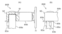
図17(A)及び図17(B)は変形例のタッチパネル保持機構86Bにおける第1アーム88aと第2アーム88bの連結部付近の構成を示す。なお、図17(A)は第2アーム88aの後端付近を断面図で示し、図17(B)は側面図で示している。
図17(A)に示すように第1アーム88aの上端には樹脂カラー91を介挿して第2アーム88bの後端(基端)が、第1アーム88aの中心軸の回りで回転自在に保持された回転保持部92が形成されている。なお、この回転保持部92は、第2アーム88bを回転自在に支持する構造で、その際第2アーム88bをマニュアルで回転(回動)させるようにしても良いし、モータなどを用いてスイッチの操作で回転駆動できる構造にしても良い。
また、図17(B)に示すように第1アーム88aにおける周方向には第1センサ83aと第2センサ83bとが、例えば90°なす角度で図示しない固定ネジ等で取り付けられており、かつ第2アーム88bの後端には検出片89aと89bとが、周方向に例えば90°なす角度で図示しない固定ネジ等で固定されて設けてある。
FIG. 17A and FIG. 17B show a configuration in the vicinity of the connecting portion of the first arm 88a and the
As shown in FIG. 17A, a
Further, as shown in FIG. 17B, in the circumferential direction of the first arm 88a, the first sensor 83a and the
本変形例では、各センサ83a、83bは、各センサの取付位置からー45°〜+45°の範囲内に検出片が存在するか否かを検出する。そして、MPU51は、両センサ83a、83bの検出信号により、タッチパネル71の表示面が設定されている向き或いは方向(その向きの中心角度をθ)を検出して表示画面の切替制御を行う。なお、図17(A)及び図17(B)においては、トロリ4の正面は紙面の垂直方向手前となる。
図18は本変形例におけるタッチパネル71の表示面の切替制御の動作を示す。以下の説明では、タッチパネル71の表示面の方向がトロリ4の正面と同じ向きの時を角度0として説明する。
この動作が開始すると、最初のステップS41においてMPU51は、タッチパネル71の表示面が正面側の向き(換言するとー45°≦θ≦+45°)かの判定を、第1及び第2センサ83a、83bの検出信号により行う。
In this modification, each of the
FIG. 18 shows an operation of switching the display surface of the
When this operation is started, in the first step S41, the
そして、表示面が正面側の向きであると判定した場合には、次のステップS42においてMPU51は、タッチパネル71の表示面に表示用GUIを表示する制御を行った後、ステップS41に戻る。
一方、ステップS41の判定において、表示面が正面側の向きでないと判定した場合には、ステップS43においてMPU51は、タッチパネル71の表示面が右側面側の向き(換言すると+45°<θ≦+135°)かの判定を、第1及び第2センサ83a、83bの検出信号により行う。
そして、表示面が右側面側の向きであると判定した場合には、次のステップS44においてMPU51は、タッチパネル71の表示面に操作用GUIを表示する制御を行った後、ステップS41に戻る。
If it is determined that the display surface is facing the front side, the
On the other hand, if it is determined in step S41 that the display surface is not directed to the front side, the
If it is determined that the display surface is oriented to the right side, the
一方、ステップS43の判定において、表示面が右側面側の向きでないと判定した場合には、ステップS45においてMPU51は、タッチパネル71の表示面が背面側の向き(換言するとー135°≦θ<+135°)かの判定を、第1及び第2センサ83a、83bの検出信号により行う。
そして、表示面が背面側の向きであると判定した場合には、次のステップS46においてMPU51は、タッチパネル71の表示面に麻酔用GUIを表示する制御を行った後、ステップS41に戻る。
一方、ステップS45の判定において、表示面が背面側の向きでないと判定した場合には、ステップS41に戻る。
このように動作する変形例によれば、コストを削減できると共に、狭い設置スペースで使用することができる。
On the other hand, if it is determined in step S43 that the display surface is not oriented on the right side, in step S45, the
If it is determined that the display surface is oriented toward the back side, the
On the other hand, if it is determined in step S45 that the display surface is not directed to the back side, the process returns to step S41.
According to the modified example that operates in this way, the cost can be reduced and the apparatus can be used in a small installation space.
なお、本実施例及びその変形例においては、回転自在に保持されたタッチパネル71の表示面の方向(向き)を2つのセンサ83a、83bにより検出するセンサ手段を用いているが、これに限定されるものでなく、例えば回転自在な軸にロータリエンコーダを取り付けてその検出信号により、所定の方向を検出するようにしても良い。
また、本実施例及び変形例において、タッチパネル71の代わりにパネルPC13等を用いても良い。
なお、上述した各実施例等を部分的に組み合わせる等して構成される実施例等も本発明に属する。
In the present embodiment and its modifications, sensor means for detecting the direction (orientation) of the display surface of the
In the present embodiment and the modification, the
It should be noted that embodiments configured by partially combining the above-described embodiments and the like also belong to the present invention.
内視鏡による観察下で、複数の周辺装置を用いて外科手術等を行う場合、操作パネルと表示パネルとの機能をその表示画面を切り替えて表示させる制御を行う構成とすることにより、コスト削減を可能にすると共に、狭い設置スペースで使用可能にしている。 Cost reduction by switching the display screen to display the functions of the operation panel and display panel when performing surgery, etc. using multiple peripheral devices under observation with an endoscope. As well as being usable in a small installation space.
1…医療用内視鏡システム
2…手術台
3…患者
4、5…トロリ
6a、6b…TVカメラ装置
13…パネルPC
14…システムコントローラ
16a、16b…内視鏡
41…パネルPC取付マウント
42…アーム
43…パネルPC取付検出センサ
51、61…MPU
52、62…メモリ
53、63…無線LANアダプタ
56、66…ハードディスク
65…制御プログラム
65a…GUI情報格納部
65b…画面切替処理機能
67…画像表示部&タッチセンサ部
DESCRIPTION OF
DESCRIPTION OF
52, 62 ...
Claims (6)
表示を行う表示部及び操作入力を検出するセンサ部を備えたパネル部と、
表示用グラフィカルユーザインタフェース情報及び操作用グラフィカルユーザインタフェース情報とを記録する情報記録手段と、
前記パネル部が少なくとも1つの所定位置にあるか否かを検出する検出手段と、
前記検出手段による検出信号に基づき、前記情報記録手段に記録された前記表示用グラフィカルユーザインタフェース情報及び操作用グラフィカルユーザインタフェース情報を切り替えて前記表示部に表示させる制御を行う表示切替制御手段と、
を具備したことを特徴とする医療用システム。 In a medical system comprising a plurality of medical devices,
A panel unit having a display unit for displaying and a sensor unit for detecting an operation input;
Information recording means for recording graphical user interface information for display and graphical user interface information for operation;
Detecting means for detecting whether or not the panel portion is at least one predetermined position;
Display switching control means for performing control for switching the display graphical user interface information and the operation graphical user interface information recorded in the information recording means and displaying them on the display unit based on a detection signal by the detection means;
A medical system characterized by comprising:
Priority Applications (2)
| Application Number | Priority Date | Filing Date | Title |
|---|---|---|---|
| JP2005376238A JP2007175231A (en) | 2005-12-27 | 2005-12-27 | Medical system |
| US11/715,001 US20070225690A1 (en) | 2005-12-27 | 2007-03-07 | Medical system and medical display apparatus |
Applications Claiming Priority (1)
| Application Number | Priority Date | Filing Date | Title |
|---|---|---|---|
| JP2005376238A JP2007175231A (en) | 2005-12-27 | 2005-12-27 | Medical system |
Publications (1)
| Publication Number | Publication Date |
|---|---|
| JP2007175231A true JP2007175231A (en) | 2007-07-12 |
Family
ID=38301008
Family Applications (1)
| Application Number | Title | Priority Date | Filing Date |
|---|---|---|---|
| JP2005376238A Pending JP2007175231A (en) | 2005-12-27 | 2005-12-27 | Medical system |
Country Status (2)
| Country | Link |
|---|---|
| US (1) | US20070225690A1 (en) |
| JP (1) | JP2007175231A (en) |
Cited By (4)
| Publication number | Priority date | Publication date | Assignee | Title |
|---|---|---|---|---|
| JP2017070477A (en) * | 2015-10-07 | 2017-04-13 | オリンパス株式会社 | Endoscope |
| US10130240B2 (en) | 2014-08-04 | 2018-11-20 | Olympus Corporation | Medical system |
| US10667670B2 (en) | 2011-11-30 | 2020-06-02 | Fujifilm Corporation | Medical system |
| JP2021509057A (en) * | 2017-12-28 | 2021-03-18 | エシコン エルエルシーEthicon LLC | Surgical system for presenting information interpreted from external data |
Families Citing this family (123)
| Publication number | Priority date | Publication date | Assignee | Title |
|---|---|---|---|---|
| AU2009231779B2 (en) | 2008-04-01 | 2015-01-15 | Amo Development, Llc | System and method of iris-pupil contrast enhancement |
| CA2731810C (en) * | 2008-04-01 | 2017-07-04 | Amo Development, Llc | Ophthalmic laser system with high resolution imaging and kit therefor |
| DE502008002472D1 (en) | 2008-04-16 | 2011-03-10 | Siemens Ag | Support frame for receiving a control panel |
| US8758234B2 (en) | 2008-07-08 | 2014-06-24 | Karl Storz Imaging, Inc. | Solid state variable direction of view endoscope |
| US8771177B2 (en) * | 2008-07-08 | 2014-07-08 | Karl Storz Imaging, Inc. | Wide angle flexible endoscope |
| US10092169B2 (en) | 2008-07-08 | 2018-10-09 | Karl Storz Imaging, Inc. | Solid state variable direction of view endoscope |
| KR101023655B1 (en) * | 2008-10-08 | 2011-03-25 | 주식회사 메디슨 | Ultrasound system |
| CN102579139A (en) * | 2011-01-18 | 2012-07-18 | 研华股份有限公司 | Integrated mobile medical system |
| CN103890765A (en) * | 2011-09-07 | 2014-06-25 | 皇家飞利浦有限公司 | Contactless remote control system and method for medical devices |
| US11871901B2 (en) | 2012-05-20 | 2024-01-16 | Cilag Gmbh International | Method for situational awareness for surgical network or surgical network connected device capable of adjusting function based on a sensed situation or usage |
| US11504192B2 (en) | 2014-10-30 | 2022-11-22 | Cilag Gmbh International | Method of hub communication with surgical instrument systems |
| US11051836B2 (en) | 2017-10-30 | 2021-07-06 | Cilag Gmbh International | Surgical clip applier comprising an empty clip cartridge lockout |
| US11564756B2 (en) | 2017-10-30 | 2023-01-31 | Cilag Gmbh International | Method of hub communication with surgical instrument systems |
| US11510741B2 (en) | 2017-10-30 | 2022-11-29 | Cilag Gmbh International | Method for producing a surgical instrument comprising a smart electrical system |
| US11229436B2 (en) | 2017-10-30 | 2022-01-25 | Cilag Gmbh International | Surgical system comprising a surgical tool and a surgical hub |
| US11801098B2 (en) | 2017-10-30 | 2023-10-31 | Cilag Gmbh International | Method of hub communication with surgical instrument systems |
| US11291510B2 (en) | 2017-10-30 | 2022-04-05 | Cilag Gmbh International | Method of hub communication with surgical instrument systems |
| US11317919B2 (en) | 2017-10-30 | 2022-05-03 | Cilag Gmbh International | Clip applier comprising a clip crimping system |
| US11911045B2 (en) | 2017-10-30 | 2024-02-27 | Cllag GmbH International | Method for operating a powered articulating multi-clip applier |
| US11311342B2 (en) | 2017-10-30 | 2022-04-26 | Cilag Gmbh International | Method for communicating with surgical instrument systems |
| US11406390B2 (en) | 2017-10-30 | 2022-08-09 | Cilag Gmbh International | Clip applier comprising interchangeable clip reloads |
| US11304745B2 (en) | 2017-12-28 | 2022-04-19 | Cilag Gmbh International | Surgical evacuation sensing and display |
| US11166772B2 (en) | 2017-12-28 | 2021-11-09 | Cilag Gmbh International | Surgical hub coordination of control and communication of operating room devices |
| US11659023B2 (en) | 2017-12-28 | 2023-05-23 | Cilag Gmbh International | Method of hub communication |
| US11160605B2 (en) | 2017-12-28 | 2021-11-02 | Cilag Gmbh International | Surgical evacuation sensing and motor control |
| US11633237B2 (en) | 2017-12-28 | 2023-04-25 | Cilag Gmbh International | Usage and technique analysis of surgeon / staff performance against a baseline to optimize device utilization and performance for both current and future procedures |
| US11666331B2 (en) | 2017-12-28 | 2023-06-06 | Cilag Gmbh International | Systems for detecting proximity of surgical end effector to cancerous tissue |
| US11612444B2 (en) | 2017-12-28 | 2023-03-28 | Cilag Gmbh International | Adjustment of a surgical device function based on situational awareness |
| US11937769B2 (en) | 2017-12-28 | 2024-03-26 | Cilag Gmbh International | Method of hub communication, processing, storage and display |
| US11786245B2 (en) | 2017-12-28 | 2023-10-17 | Cilag Gmbh International | Surgical systems with prioritized data transmission capabilities |
| US11419630B2 (en) | 2017-12-28 | 2022-08-23 | Cilag Gmbh International | Surgical system distributed processing |
| US11234756B2 (en) | 2017-12-28 | 2022-02-01 | Cilag Gmbh International | Powered surgical tool with predefined adjustable control algorithm for controlling end effector parameter |
| US11744604B2 (en) | 2017-12-28 | 2023-09-05 | Cilag Gmbh International | Surgical instrument with a hardware-only control circuit |
| US11896443B2 (en) | 2017-12-28 | 2024-02-13 | Cilag Gmbh International | Control of a surgical system through a surgical barrier |
| US11672605B2 (en) | 2017-12-28 | 2023-06-13 | Cilag Gmbh International | Sterile field interactive control displays |
| US11678881B2 (en) | 2017-12-28 | 2023-06-20 | Cilag Gmbh International | Spatial awareness of surgical hubs in operating rooms |
| US11266468B2 (en) | 2017-12-28 | 2022-03-08 | Cilag Gmbh International | Cooperative utilization of data derived from secondary sources by intelligent surgical hubs |
| US11324557B2 (en) | 2017-12-28 | 2022-05-10 | Cilag Gmbh International | Surgical instrument with a sensing array |
| US20190201042A1 (en) | 2017-12-28 | 2019-07-04 | Ethicon Llc | Determining the state of an ultrasonic electromechanical system according to frequency shift |
| US11096693B2 (en) | 2017-12-28 | 2021-08-24 | Cilag Gmbh International | Adjustment of staple height of at least one row of staples based on the sensed tissue thickness or force in closing |
| US11424027B2 (en) | 2017-12-28 | 2022-08-23 | Cilag Gmbh International | Method for operating surgical instrument systems |
| US11576677B2 (en) | 2017-12-28 | 2023-02-14 | Cilag Gmbh International | Method of hub communication, processing, display, and cloud analytics |
| US20190201039A1 (en) | 2017-12-28 | 2019-07-04 | Ethicon Llc | Situational awareness of electrosurgical systems |
| US11304763B2 (en) | 2017-12-28 | 2022-04-19 | Cilag Gmbh International | Image capturing of the areas outside the abdomen to improve placement and control of a surgical device in use |
| US11832899B2 (en) | 2017-12-28 | 2023-12-05 | Cilag Gmbh International | Surgical systems with autonomously adjustable control programs |
| US11432885B2 (en) | 2017-12-28 | 2022-09-06 | Cilag Gmbh International | Sensing arrangements for robot-assisted surgical platforms |
| US10892995B2 (en) | 2017-12-28 | 2021-01-12 | Ethicon Llc | Surgical network determination of prioritization of communication, interaction, or processing based on system or device needs |
| US11571234B2 (en) | 2017-12-28 | 2023-02-07 | Cilag Gmbh International | Temperature control of ultrasonic end effector and control system therefor |
| US11818052B2 (en) | 2017-12-28 | 2023-11-14 | Cilag Gmbh International | Surgical network determination of prioritization of communication, interaction, or processing based on system or device needs |
| US11864728B2 (en) | 2017-12-28 | 2024-01-09 | Cilag Gmbh International | Characterization of tissue irregularities through the use of mono-chromatic light refractivity |
| US11857152B2 (en) | 2017-12-28 | 2024-01-02 | Cilag Gmbh International | Surgical hub spatial awareness to determine devices in operating theater |
| US11419667B2 (en) | 2017-12-28 | 2022-08-23 | Cilag Gmbh International | Ultrasonic energy device which varies pressure applied by clamp arm to provide threshold control pressure at a cut progression location |
| US11903601B2 (en) | 2017-12-28 | 2024-02-20 | Cilag Gmbh International | Surgical instrument comprising a plurality of drive systems |
| US11464559B2 (en) | 2017-12-28 | 2022-10-11 | Cilag Gmbh International | Estimating state of ultrasonic end effector and control system therefor |
| US20190201118A1 (en) | 2017-12-28 | 2019-07-04 | Ethicon Llc | Display arrangements for robot-assisted surgical platforms |
| US11253315B2 (en) | 2017-12-28 | 2022-02-22 | Cilag Gmbh International | Increasing radio frequency to create pad-less monopolar loop |
| US11132462B2 (en) | 2017-12-28 | 2021-09-28 | Cilag Gmbh International | Data stripping method to interrogate patient records and create anonymized record |
| US11529187B2 (en) | 2017-12-28 | 2022-12-20 | Cilag Gmbh International | Surgical evacuation sensor arrangements |
| US11832840B2 (en) | 2017-12-28 | 2023-12-05 | Cilag Gmbh International | Surgical instrument having a flexible circuit |
| US11364075B2 (en) | 2017-12-28 | 2022-06-21 | Cilag Gmbh International | Radio frequency energy device for delivering combined electrical signals |
| US11540855B2 (en) | 2017-12-28 | 2023-01-03 | Cilag Gmbh International | Controlling activation of an ultrasonic surgical instrument according to the presence of tissue |
| US11423007B2 (en) | 2017-12-28 | 2022-08-23 | Cilag Gmbh International | Adjustment of device control programs based on stratified contextual data in addition to the data |
| US11257589B2 (en) | 2017-12-28 | 2022-02-22 | Cilag Gmbh International | Real-time analysis of comprehensive cost of all instrumentation used in surgery utilizing data fluidity to track instruments through stocking and in-house processes |
| US11304720B2 (en) | 2017-12-28 | 2022-04-19 | Cilag Gmbh International | Activation of energy devices |
| US11596291B2 (en) | 2017-12-28 | 2023-03-07 | Cilag Gmbh International | Method of compressing tissue within a stapling device and simultaneously displaying of the location of the tissue within the jaws |
| US11786251B2 (en) | 2017-12-28 | 2023-10-17 | Cilag Gmbh International | Method for adaptive control schemes for surgical network control and interaction |
| US11559307B2 (en) | 2017-12-28 | 2023-01-24 | Cilag Gmbh International | Method of robotic hub communication, detection, and control |
| US10758310B2 (en) | 2017-12-28 | 2020-09-01 | Ethicon Llc | Wireless pairing of a surgical device with another device within a sterile surgical field based on the usage and situational awareness of devices |
| US11389164B2 (en) | 2017-12-28 | 2022-07-19 | Cilag Gmbh International | Method of using reinforced flexible circuits with multiple sensors to optimize performance of radio frequency devices |
| US11589888B2 (en) | 2017-12-28 | 2023-02-28 | Cilag Gmbh International | Method for controlling smart energy devices |
| US11602393B2 (en) | 2017-12-28 | 2023-03-14 | Cilag Gmbh International | Surgical evacuation sensing and generator control |
| US11410259B2 (en) | 2017-12-28 | 2022-08-09 | Cilag Gmbh International | Adaptive control program updates for surgical devices |
| US11317937B2 (en) | 2018-03-08 | 2022-05-03 | Cilag Gmbh International | Determining the state of an ultrasonic end effector |
| US11464535B2 (en) | 2017-12-28 | 2022-10-11 | Cilag Gmbh International | Detection of end effector emersion in liquid |
| US11291495B2 (en) | 2017-12-28 | 2022-04-05 | Cilag Gmbh International | Interruption of energy due to inadvertent capacitive coupling |
| US11696760B2 (en) | 2017-12-28 | 2023-07-11 | Cilag Gmbh International | Safety systems for smart powered surgical stapling |
| US11278281B2 (en) | 2017-12-28 | 2022-03-22 | Cilag Gmbh International | Interactive surgical system |
| US11446052B2 (en) | 2017-12-28 | 2022-09-20 | Cilag Gmbh International | Variation of radio frequency and ultrasonic power level in cooperation with varying clamp arm pressure to achieve predefined heat flux or power applied to tissue |
| US11376002B2 (en) | 2017-12-28 | 2022-07-05 | Cilag Gmbh International | Surgical instrument cartridge sensor assemblies |
| US11109866B2 (en) | 2017-12-28 | 2021-09-07 | Cilag Gmbh International | Method for circular stapler control algorithm adjustment based on situational awareness |
| US11273001B2 (en) | 2017-12-28 | 2022-03-15 | Cilag Gmbh International | Surgical hub and modular device response adjustment based on situational awareness |
| US20190201113A1 (en) | 2017-12-28 | 2019-07-04 | Ethicon Llc | Controls for robot-assisted surgical platforms |
| US11311306B2 (en) | 2017-12-28 | 2022-04-26 | Cilag Gmbh International | Surgical systems for detecting end effector tissue distribution irregularities |
| US11179208B2 (en) | 2017-12-28 | 2021-11-23 | Cilag Gmbh International | Cloud-based medical analytics for security and authentication trends and reactive measures |
| US11202570B2 (en) | 2017-12-28 | 2021-12-21 | Cilag Gmbh International | Communication hub and storage device for storing parameters and status of a surgical device to be shared with cloud based analytics systems |
| US11559308B2 (en) | 2017-12-28 | 2023-01-24 | Cilag Gmbh International | Method for smart energy device infrastructure |
| US11896322B2 (en) | 2017-12-28 | 2024-02-13 | Cilag Gmbh International | Sensing the patient position and contact utilizing the mono-polar return pad electrode to provide situational awareness to the hub |
| US11304699B2 (en) | 2017-12-28 | 2022-04-19 | Cilag Gmbh International | Method for adaptive control schemes for surgical network control and interaction |
| US11308075B2 (en) | 2017-12-28 | 2022-04-19 | Cilag Gmbh International | Surgical network, instrument, and cloud responses based on validation of received dataset and authentication of its source and integrity |
| US11284936B2 (en) | 2017-12-28 | 2022-03-29 | Cilag Gmbh International | Surgical instrument having a flexible electrode |
| US11844545B2 (en) | 2018-03-08 | 2023-12-19 | Cilag Gmbh International | Calcified vessel identification |
| US20190274662A1 (en) | 2018-03-08 | 2019-09-12 | Ethicon Llc | Adjustment of complex impedance to compensate for lost power in an articulating ultrasonic device |
| US11259830B2 (en) | 2018-03-08 | 2022-03-01 | Cilag Gmbh International | Methods for controlling temperature in ultrasonic device |
| US10512191B2 (en) * | 2018-03-26 | 2019-12-17 | Augustine Biomedical + Design, LLC | Relocation module for patient monitors and surgical equipment |
| US11426318B2 (en) | 2020-05-20 | 2022-08-30 | Augustine Biomedical + Design, LLC | Medical module including automated dose-response record system |
| US11219570B2 (en) | 2018-03-26 | 2022-01-11 | Augustine Biomedical + Design, LLC | Relocation module and methods for surgical equipment |
| US10869800B2 (en) * | 2018-03-26 | 2020-12-22 | Augustine Biomedical + Design, LLC | Relocation module and methods for surgical equipment |
| US10507153B2 (en) | 2018-03-26 | 2019-12-17 | Augustine Biomedical + Design, LLC | Relocation modules and methods for surgical field |
| US11291602B2 (en) | 2018-03-26 | 2022-04-05 | Augustine Biomedical + Design, LLC | Relocation module and methods for surgical equipment |
| US11446196B2 (en) | 2018-03-26 | 2022-09-20 | Augustine Biomedical + Design, LLC | Relocation module and methods for surgical equipment |
| US11160710B1 (en) | 2020-05-20 | 2021-11-02 | Augustine Biomedical + Design, LLC | Relocation module and methods for surgical equipment |
| US11432982B2 (en) | 2018-03-26 | 2022-09-06 | Augustine Biomedical + Design, LLC | Relocation module and methods for surgical equipment |
| US11259806B2 (en) | 2018-03-28 | 2022-03-01 | Cilag Gmbh International | Surgical stapling devices with features for blocking advancement of a camming assembly of an incompatible cartridge installed therein |
| US11471156B2 (en) | 2018-03-28 | 2022-10-18 | Cilag Gmbh International | Surgical stapling devices with improved rotary driven closure systems |
| US11090047B2 (en) | 2018-03-28 | 2021-08-17 | Cilag Gmbh International | Surgical instrument comprising an adaptive control system |
| US11197668B2 (en) | 2018-03-28 | 2021-12-14 | Cilag Gmbh International | Surgical stapling assembly comprising a lockout and an exterior access orifice to permit artificial unlocking of the lockout |
| US11207067B2 (en) | 2018-03-28 | 2021-12-28 | Cilag Gmbh International | Surgical stapling device with separate rotary driven closure and firing systems and firing member that engages both jaws while firing |
| US11278280B2 (en) | 2018-03-28 | 2022-03-22 | Cilag Gmbh International | Surgical instrument comprising a jaw closure lockout |
| US11219453B2 (en) | 2018-03-28 | 2022-01-11 | Cilag Gmbh International | Surgical stapling devices with cartridge compatible closure and firing lockout arrangements |
| US11464511B2 (en) | 2019-02-19 | 2022-10-11 | Cilag Gmbh International | Surgical staple cartridges with movable authentication key arrangements |
| US11317915B2 (en) | 2019-02-19 | 2022-05-03 | Cilag Gmbh International | Universal cartridge based key feature that unlocks multiple lockout arrangements in different surgical staplers |
| US11369377B2 (en) | 2019-02-19 | 2022-06-28 | Cilag Gmbh International | Surgical stapling assembly with cartridge based retainer configured to unlock a firing lockout |
| US11357503B2 (en) | 2019-02-19 | 2022-06-14 | Cilag Gmbh International | Staple cartridge retainers with frangible retention features and methods of using same |
| US11517309B2 (en) | 2019-02-19 | 2022-12-06 | Cilag Gmbh International | Staple cartridge retainer with retractable authentication key |
| USD964564S1 (en) | 2019-06-25 | 2022-09-20 | Cilag Gmbh International | Surgical staple cartridge retainer with a closure system authentication key |
| USD950728S1 (en) | 2019-06-25 | 2022-05-03 | Cilag Gmbh International | Surgical staple cartridge |
| USD952144S1 (en) | 2019-06-25 | 2022-05-17 | Cilag Gmbh International | Surgical staple cartridge retainer with firing system authentication key |
| US20220104806A1 (en) * | 2020-10-02 | 2022-04-07 | Ethicon Llc | Surgical instrument with adaptive configuration control |
| US11672534B2 (en) | 2020-10-02 | 2023-06-13 | Cilag Gmbh International | Communication capability of a smart stapler |
| US11748924B2 (en) | 2020-10-02 | 2023-09-05 | Cilag Gmbh International | Tiered system display control based on capacity and user operation |
| US11877897B2 (en) | 2020-10-02 | 2024-01-23 | Cilag Gmbh International | Situational awareness of instruments location and individualization of users to control displays |
| US11830602B2 (en) | 2020-10-02 | 2023-11-28 | Cilag Gmbh International | Surgical hub having variable interconnectivity capabilities |
| US11963683B2 (en) | 2020-10-02 | 2024-04-23 | Cilag Gmbh International | Method for operating tiered operation modes in a surgical system |
Family Cites Families (5)
| Publication number | Priority date | Publication date | Assignee | Title |
|---|---|---|---|---|
| US6437836B1 (en) * | 1998-09-21 | 2002-08-20 | Navispace, Inc. | Extended functionally remote control system and method therefore |
| US6597374B1 (en) * | 1998-11-12 | 2003-07-22 | Microsoft Corporation | Activity based remote control unit |
| US6480762B1 (en) * | 1999-09-27 | 2002-11-12 | Olympus Optical Co., Ltd. | Medical apparatus supporting system |
| US6975968B2 (en) * | 2001-02-08 | 2005-12-13 | Olympus Corporation | Medical system control apparatus, and method for dealing with trouble with the medical system control apparatus |
| US20050162399A1 (en) * | 2004-01-23 | 2005-07-28 | Kabushiki Kaisha Toshiba | Displaying and inputting apparatus |
-
2005
- 2005-12-27 JP JP2005376238A patent/JP2007175231A/en active Pending
-
2007
- 2007-03-07 US US11/715,001 patent/US20070225690A1/en not_active Abandoned
Cited By (5)
| Publication number | Priority date | Publication date | Assignee | Title |
|---|---|---|---|---|
| US10667670B2 (en) | 2011-11-30 | 2020-06-02 | Fujifilm Corporation | Medical system |
| US10130240B2 (en) | 2014-08-04 | 2018-11-20 | Olympus Corporation | Medical system |
| JP2017070477A (en) * | 2015-10-07 | 2017-04-13 | オリンパス株式会社 | Endoscope |
| JP2021509057A (en) * | 2017-12-28 | 2021-03-18 | エシコン エルエルシーEthicon LLC | Surgical system for presenting information interpreted from external data |
| JP7330980B2 (en) | 2017-12-28 | 2023-08-22 | エシコン エルエルシー | Surgical system for presenting information interpreted from external data |
Also Published As
| Publication number | Publication date |
|---|---|
| US20070225690A1 (en) | 2007-09-27 |
Similar Documents
| Publication | Publication Date | Title |
|---|---|---|
| JP2007175231A (en) | Medical system | |
| JP4813349B2 (en) | Endoscope system | |
| US20050283138A1 (en) | Operating room control system | |
| JP2006218129A (en) | Surgery supporting system | |
| JP2008000282A (en) | Procedure image recording control system and surgery system | |
| JP2003325543A (en) | Medical operation system and medical operation apparatus thereof | |
| JP2001314411A (en) | Surgical operation system | |
| US20060200354A1 (en) | Medical practice support system | |
| US10130240B2 (en) | Medical system | |
| JP5165338B2 (en) | Endoscope system | |
| EP2119413B1 (en) | Medical system and medical display device | |
| JP2007080094A (en) | Application starting management system | |
| JP2006223374A (en) | Apparatus, system and method for surgery supporting | |
| JP2006198031A (en) | Surgery support system | |
| JP2006221583A (en) | Medical treatment support system | |
| JP5010778B2 (en) | Endoscopic surgery system | |
| JPH07303654A (en) | System control device | |
| JP2001120492A (en) | Endoscope system device | |
| JP4727066B2 (en) | Endoscope system | |
| JP2002336194A (en) | Medical system | |
| JP4533638B2 (en) | Virtual image display system | |
| JP2001238205A (en) | Endoscope system | |
| JP2006288956A (en) | Surgery system | |
| JP3866990B2 (en) | Control system | |
| JP4127769B2 (en) | Medical control system |