US11249285B2 - Imaging lens with five lenses of --+-+ refractive powers - Google Patents
Imaging lens with five lenses of --+-+ refractive powers Download PDFInfo
- Publication number
- US11249285B2 US11249285B2 US16/663,388 US201916663388A US11249285B2 US 11249285 B2 US11249285 B2 US 11249285B2 US 201916663388 A US201916663388 A US 201916663388A US 11249285 B2 US11249285 B2 US 11249285B2
- Authority
- US
- United States
- Prior art keywords
- lens
- refractive index
- represented
- imaging
- temperature coefficient
- Prior art date
- Legal status (The legal status is an assumption and is not a legal conclusion. Google has not performed a legal analysis and makes no representation as to the accuracy of the status listed.)
- Active, expires
Links
Images


Classifications
-
- G—PHYSICS
- G02—OPTICS
- G02B—OPTICAL ELEMENTS, SYSTEMS OR APPARATUS
- G02B13/00—Optical objectives specially designed for the purposes specified below
- G02B13/04—Reversed telephoto objectives
-
- G—PHYSICS
- G02—OPTICS
- G02B—OPTICAL ELEMENTS, SYSTEMS OR APPARATUS
- G02B13/00—Optical objectives specially designed for the purposes specified below
- G02B13/001—Miniaturised objectives for electronic devices, e.g. portable telephones, webcams, PDAs, small digital cameras
- G02B13/0015—Miniaturised objectives for electronic devices, e.g. portable telephones, webcams, PDAs, small digital cameras characterised by the lens design
- G02B13/002—Miniaturised objectives for electronic devices, e.g. portable telephones, webcams, PDAs, small digital cameras characterised by the lens design having at least one aspherical surface
- G02B13/0045—Miniaturised objectives for electronic devices, e.g. portable telephones, webcams, PDAs, small digital cameras characterised by the lens design having at least one aspherical surface having five or more lenses
-
- G—PHYSICS
- G02—OPTICS
- G02B—OPTICAL ELEMENTS, SYSTEMS OR APPARATUS
- G02B7/00—Mountings, adjusting means, or light-tight connections, for optical elements
- G02B7/02—Mountings, adjusting means, or light-tight connections, for optical elements for lenses
- G02B7/028—Mountings, adjusting means, or light-tight connections, for optical elements for lenses with means for compensating for changes in temperature or for controlling the temperature; thermal stabilisation
-
- G—PHYSICS
- G02—OPTICS
- G02B—OPTICAL ELEMENTS, SYSTEMS OR APPARATUS
- G02B9/00—Optical objectives characterised both by the number of the components and their arrangements according to their sign, i.e. + or -
- G02B9/60—Optical objectives characterised both by the number of the components and their arrangements according to their sign, i.e. + or - having five components only
Definitions
- the present application relates to an imaging lens having a configuration of five lenses in five groups.
- an imaging lens for the surveillance cameras and in-vehicle cameras for example, an imaging lens having a configuration of five lenses in five groups has been described (JP2003-307674A, JP3943988B (corresponding to U.S. Pat. No. 6,833,967B2), JP5065159B (corresponding to U.S. Pat. No. 7,684,127B2), and JP2016-057563A). Since the in-vehicle cameras, etc.
- JP5272614B (corresponding to U.S. Pat. No. 8,830,298B2)
- JP2014-197130A corresponding to U.S. Pat. No. 9,310,589B2
- an imaging lens having a configuration of five lenses in five groups to be used other than the in-vehicle cameras, etc. for example, an imaging lens has been described in each of JPH05-045583A and JPH09-090213A. Further, as an imaging lens performing temperature compensation to be used other than the in-vehicle cameras, etc., an imaging lens has been described in each of JP2016-114648A (corresponding to U.S. Pat. No. 9,411,135B2), JP2016-126133A and JP2016-142767A.
- the in-vehicle cameras, etc. are used in a harsh environment, the in-vehicle cameras, etc. are required to have durability against changes in environmental temperature and so on (hereinafter referred to as the environmental resistance).
- the environmental temperature may be minus degrees Celsius on the low temperature side, and may be 100 degrees Celsius or higher on the high temperature side.
- the imaging lens constituting the in-vehicle cameras, etc. is required to perform the temperature compensation in a very large range.
- the imaging lens is required to have a simple configuration with lower cost and excellent mass productivity.
- the number of lenses to be configured is as small as possible.
- error amounts with respect to design values such as thickness or inclination due to temperature change (including manufacturing errors) has little impact to the optical performance such as aberrations of the imaging lens (hereinafter referred to as “low error sensitivity”).
- An object of the present application is to provide a imaging lens suitable for in-vehicle cameras, etc., with lower cost and excellent mass productivity.
- An imaging lens may include, in order from an object side, a first lens, a second lens, a third lens, a fourth lens, a fifth lens, and aperture stop.
- the first lens may have negative power.
- the second lens may have negative power.
- the third lens may have positive power.
- the fourth lens may have negative power.
- the fifth lens may have positive power.
- the aperture stop may be disposed between the second lens and the third lens. At least one of the third lens and the fifth lens may be formed of glass having a negative temperature coefficient of refractive index.
- a focal length of an entire system of the imaging lens is represented by f
- the temperature coefficient of refractive index of the at least one of the third lens and the fifth lens formed of glass having a negative temperature coefficient of refractive index is represented by dn/dt
- the following conditions may be satisfied: dn/dt ⁇ 0.5 and ⁇ 2.90 ⁇ f /( dn/dt ) ⁇ 0.65.
- the third lens may be formed of glass having a negative temperature coefficient of refractive index, and the focal length of the entire system of the imaging lens is represented by f, the temperature coefficient of refractive index of the third lens is represented by dn 3 /dt, and a following condition may be satisfied: ⁇ 2.90 ⁇ f /( dn 3 /dt ) ⁇ 0.80.
- the third lens may be formed of glass having a negative temperature coefficient of refractive index, and a focal length of the third lens is represented by f 3 , the temperature coefficient of refractive index of the third lens is represented by dn 3 /dt, and a following condition may be satisfied: ⁇ 6.50 ⁇ f 3 /( dn 3 /dt ) ⁇ 0.80.
- Third lens may be formed of glass having a negative temperature coefficient of refractive index, and a focal length of the third lens is represented by f 3 ; a focal length of a rear group including the third lens, the fourth lens, and the fifth lens is represented by f 35 ; and a following condition may be satisfied: 0.60 ⁇ f 3 /f 35 ⁇ 2.05.
- the fifth lens may be formed of glass having a negative temperature coefficient of refractive index, and the focal length of the entire system of the imaging lens is represented by f, the temperature coefficient of refractive index of the fifth lens is represented by dn 5 /dt, and a following condition may be satisfied: ⁇ 2.50 ⁇ f /( dn 5 /dt ) ⁇ 0.65.
- the fifth lens may be formed of glass having a negative temperature coefficient of refractive index, and a focal length of the fifth lens is represented by f 5 , the temperature coefficient of refractive index of the fifth lens is represented by dn 5 /dt, and a following condition may be satisfied: ⁇ 8.50 ⁇ f 5 /( dn 5 /dt ) ⁇ 0.85.
- the fifth lens may be formed of glass having a negative temperature coefficient of refractive index, and a focal length of the fifth lens is represented by f 5 ; a focal length of a rear group including the third lens, the fourth lens, and the fifth lens is represented by f 35 ; and a following condition may be satisfied: 0.70 ⁇ f 5 /f 35 ⁇ 7.00.
- a focal length of the rear group including the third lens, the fourth lens, and the fifth lens is represented by f 35 ; a distance from an object side surface of the third lens to an image side surface of the fifth lens is represented by D 35 ; and a following condition may be satisfied: 0.90 ⁇ D 35 /f 35 ⁇ 1.40.
- a focal length of the rear group including the third lens, the fourth lens, and the fifth lens is represented by f 35 ; a distance from an object side surface of the first lens to an image side surface of the fifth lens is represented by TT; and a following condition may be satisfied: 2.50 ⁇ TT/f 35 ⁇ 4.50.
- the first lens may have negative power
- the second lens may have negative power
- the third lens may have positive power
- the fourth lens may have negative power
- the fifth lens may have positive power in order from an object side, in which at least one of the third lens and the fifth lens may be formed of glass having a negative temperature coefficient of refractive index, and the focal length of the entire system of the imaging lens is represented by f
- the temperature coefficient of refractive index of the at least one of the third lens and the fifth lens formed of glass having a negative temperature coefficient of refractive index is represented by dn/dt
- the condition ⁇ 2.90 ⁇ f/(dn/dt) ⁇ 0.65 may be satisfied. Accordingly, an imaging lens suitable for in-vehicle cameras, etc., with lower cost and excellent mass productivity can be provided.
- FIG. 1 is an external side view of an imaging lens.
- FIG. 2 is an external side view of an imaging lens of Example 1.
- FIG. 3A is a graph which illustrates astigmatism at 20° C. in Example 1.
- FIG. 3B is a graph which illustrates distortion at 20° C. in Example 1.
- FIG. 4 is a graph which illustrates MTF at 20° C. in Example 1.
- FIG. 5 is a graph which illustrates MTF at 110° C. in Example 1.
- FIG. 6 is an external side view of an imaging lens of Example 2.
- FIG. 7A is a graph which illustrates astigmatism at 20° C. in Example 2.
- FIG. 7B is a graph which illustrates distortion at 20° C. in Example 2.
- FIG. 8 is a graph which illustrates MTF at 20° C. in Example 2.
- FIG. 9 is a graph which illustrates MTF at 110° C. in Example 2.
- FIG. 10 is an external side view of an imaging lens of Example 3.
- FIG. 11A is a graph which illustrates astigmatism at 20° C. in Example 3.
- FIG. 11B is a graph which illustrates distortion at 20° C. in Example 3.
- FIG. 12 is an external side view of an imaging lens of Example 4.
- FIG. 13A is a graph which illustrates astigmatism at 20° C. in Example 4.
- FIG. 13B is a graph which illustrates distortion at 20° C. in Example 4.
- FIG. 14 is an external side view of an imaging lens of Example 5.
- FIG. 15A is a graph which illustrates astigmatism at 20° C. in Example 5.
- FIG. 15B is a graph which illustrates distortion at 20° C. in Example 5.
- FIG. 16 is an external side view of an imaging lens of Example 6.
- FIG. 17A is a graph which illustrates astigmatism at 20° C. in Example 6.
- FIG. 17B is a graph which illustrates distortion at 20° C. in Example 6.
- FIG. 18 is an external side view of an imaging lens of Example 7.
- FIG. 19A is a graph which illustrates astigmatism at 20° C. in Example 7.
- FIG. 19B is a graph which illustrates distortion at 20° C. in Example 7.
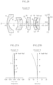
- FIG. 20 is an external side view of an imaging lens of Example 8.
- FIG. 21A is a graph which illustrates astigmatism at 20° C. in Example 8.
- FIG. 21B is a graph which illustrates distortion at 20° C. in Example 8.
- FIG. 22 is an external side view of an imaging lens of Example 9.
- FIG. 23A is a graph which illustrates astigmatism at 20° C. in Example 9.
- FIG. 23B is a graph which illustrates distortion at 20° C. in Example 9.
- FIG. 24 is an external side view of an imaging lens of Example 10.
- FIG. 25A is a graph which illustrates astigmatism at 20° C. in Example 10.
- FIG. 25B is a graph which illustrates distortion at 20° C. in Example 10.
- FIG. 26 is an external side view of an imaging lens of Example 11.
- FIG. 27A is a graph which illustrates astigmatism at 20° C. in Example 11.
- FIG. 27B is a graph which illustrates distortion at 20° C. in Example 11.
- FIG. 28 is an external side view of an imaging lens of Example 12.
- FIG. 29A is a graph which illustrates astigmatism at 20° C. in Example 12.
- FIG. 29B is a graph which illustrates distortion at 20° C. in Example 12.
- FIG. 30 is a graph which illustrates MTF at 20° C. in Example 12.
- FIG. 31 is a graph which illustrates MTF at 110° C. in Example 12.
- an imaging lens 10 is a lens for forming an image of an object on an imaging surface S 14 of an image sensor 11 , for imaging the object.
- the imaging lens 10 has a configuration of five lenses in five groups, including a first lens L 1 having negative power, a second lens L 2 having negative power, a third lens L 3 having positive power, a fourth lens L 4 having negative power, and a fifth lens L 5 having positive power, arranged in order from the object side along an optical axis Z 1 .
- the imaging lens 10 includes an aperture stop S 5 between the second lens L 2 and the third lens L 3 . Since the imaging surface S 14 of the image sensor 11 is protected with a cover glass CG, the imaging lens 10 forms an image of an object on the imaging surface S 14 via the cover glass CG.
- the first lens L 1 is formed of a material having excellent durability so that it may be exposed to the installation environment.
- the second lens L 2 has less power than the first lens L 1 , the third lens L 3 , the fourth lens L 4 , and the fifth lens L 5 , but contributes to correction of distortion and chromatic aberration.
- the third lens L 3 mainly contributes to correction of spherical aberration.
- the fourth lens L 4 mainly contributes to correction of astigmatism and chromatic aberration by forming a so-called air lens formed with air between the fourth lens L 5 .
- the fifth lens L 5 mainly contributes to correction of astigmatism and field curvature.
- the first lens L 1 , the second lens L 2 , the third lens L 3 , the fourth lens L 4 , and the fifth lens L 5 are all made of glass. Accordingly, the first lens L 1 , the second lens L 2 , the third lens L 3 , the fourth lens L 4 , and the fifth lens L 5 have higher environmental resistance than in case they are made of a resin that easily expands or contracts due to temperature changes. Note that any one or more of the first lens L 1 , the second lens L 2 , the third lens L 3 , the fourth lens L 4 , and the fifth lens L 5 can be made of resin.
- One or a plurality of lens frames and spacers (not shown) of the imaging lens 10 are made of resin, but these can be changed to a material (metal or the like) having higher environmental resistance.
- the first lens L 1 , the second lens L 2 , and the fourth lens L 4 are spherical lenses in which both the object side and the image side are formed as spherical surfaces.
- the first lens L 1 has a meniscus shape convex to the object side.
- the second lens L 2 has a meniscus shape convex to the image side.
- the fourth lens L 4 has a meniscus shape convex to the object side.
- the first lens L 1 , the second lens L 2 , and the fourth lens L 4 are all so-called concave lenses having negative power.
- the temperature coefficient of refractive index of each of the first lens L 1 , the second lens L 2 , and the fourth lens L 4 is positive.
- the second lens L 2 has less power than the first lens L 1 , the third lens L 3 , the fourth lens L 4 , and the fifth lens L 5 .
- the third lens L 3 and the fifth lens L 5 are both so-called convex lenses having positive power.
- the third lens L 3 and the fifth lens L 5 may have a meniscus shape convex to the object side or the image side, or a biconvex shape convex to both the object side and the image side.
- Each of the third lens L 3 and the fifth lens L 5 is an aspherical lens in which at least one of the object side or the image side surface is aspherical.
- At least one of the third lens L 3 and the fifth lens L 5 is formed of glass having a negative temperature coefficient of refractive index.
- the focal length of the entire system of the imaging lens 10 (unit is mm, the same applies hereinafter) is represented by f
- the temperature coefficient of refractive index of the at least one of the third lens L 3 and the fifth lens L 5 formed of glass having a negative temperature coefficient of refractive index is represented by dn/dt (That is, the temperature coefficient of refractive index of at least one of the third lens L 3 and the fifth lens L 5 is represented by dn/dt)
- the temperature coefficient dn/dt is the temperature coefficient dn 3 /dt of the refractive index n3 of the third lens L 3 in case the third lens L 3 is made of glass having a negative temperature coefficient of refractive index (see condition (3)), and is the temperature coefficient dn 5 /dt of the refractive index n5 of the fifth lens L 5 in case the fifth lens L 5 is made of glass having a negative temperature coefficient of refractive index (see condition (7)).
- both the temperature coefficient dn 3 /dt of the refractive index n3 of the third lens L 3 and the temperature coefficient dn 5 /dt of the refractive index n5 of the fifth lens L 5 satisfy the conditions (1) and (2): dn/dt ⁇ 0.5 (1) ⁇ 2.90 ⁇ f /( dn/dt ) ⁇ 0.65 (2).
- the imaging lens 10 changes its back focus BF according to partial or total expansion of the imaging lens 10 or a unit including the imaging lens 10 due to a temperature change in an environment where the imaging lens 10 is placed.
- the imaging lens 10 maintains suitable imaging performance in a wide temperature range from a low temperature (eg, 0° C. or lower) to a high temperature (eg, 100° C. or higher).
- the condition (1) represents that the temperature coefficient of refractive index is substantially negative. Therefore, the condition (1) is the condition for excluding those in which dn/dt is ⁇ 0.5 or more and hardly contributes to the adjustment of the back focus BF even if the temperature coefficient of refractive index is negative.
- the condition (2) is the condition for keeping the change of the back focus BF of the imaging lens 10 caused by the temperature change of the environment where the imaging lens 10 is placed, within a range where a suitable imaging performance can be maintained in a wide temperature range from low temperature to high temperature.
- the value off/(dn/dt) is more than the upper limit of condition (2), the back focus BF becomes too short at high temperatures, making it difficult to obtain suitable imaging performance.
- the value off/(dn/dt) is less than the lower limit of condition (2), the back focus BF becomes too long at high temperatures, making it difficult to obtain suitable imaging performance.
- the temperature compensation by adjusting the back focus BF is more effective or more accurate in case a lens having a positive power is formed of glass having a negative temperature coefficient of refractive index. Therefore, in the imaging lens 10 , since the third lens L 3 and the fifth lens L 5 have positive power, the third lens L 3 and/or the fifth lens L 5 is formed of glass having a negative temperature coefficient of refractive index.
- the back focus BF of the imaging lens 10 is the distance from the image side surface of the fifth lens L 5 to the imaging surface S 14 .
- “suitable imaging performance” means that an MTF (Modulation Transfer Function) of a line pair of 60 lines/mm (cycle/mm) (hereinafter simply referred to as the MTF) 150.4 or more (40% or more).
- MTF Modulation Transfer Function
- the imaging lens 10 can withstand practical use, and in case the MTF is about 0.4 or more, the imaging lens 10 can be used suitably.
- the imaging lens 10 satisfies at least a following condition (3), and may alternatively satisfy a following condition (4): ⁇ 2.90 ⁇ f /( dn 3 /dt ) ⁇ 0.65 (3) ⁇ 2.90 ⁇ f /( dn 3 /dt ) ⁇ 0.80 (4).
- the imaging lens 10 satisfies a following condition (5): ⁇ 6.50 ⁇ f 3 /( dn 3 /dt ) ⁇ 0.80 (5).
- the focal length of the third lens L 3 is represented by f 3
- the focal length of the rear group including the third lens L 3 , the fourth lens L 4 and the fifth lens L 5 is represented by f 35
- the imaging lens 10 satisfies a following condition (6): 0.60 ⁇ f 3 /f 35 ⁇ 2.05 (6).
- the rear group refers to a lens group included in the image plane side with respect to the aperture stop S 5 provided between the second lens L 2 and the third lens L 3 .
- the imaging lens 10 satisfies at least a following condition (7), and may alternatively satisfy a following condition (8): ⁇ 2.90 ⁇ f /( dn 5 /dt ) ⁇ 0.65 (7) ⁇ 2.50 ⁇ f /( dn 5 /dt ) ⁇ 0.65 (8).
- the imaging lens 10 satisfies a following condition (9): ⁇ 8.50 ⁇ f 5 /( dn 5 /dt ) ⁇ 0.85 (9).
- the focal length of the fifth lens L 5 is represented by f 5
- the focal length of the rear group including the third lens L 3 , the fourth lens L 4 and the fifth lens L 5 is represented by f 35
- the imaging lens 10 satisfies a following condition (10): 0.70 ⁇ f 5 /f 35 ⁇ 7.00 (10).
- the imaging lens 10 satisfies both the condition (3) or (4) for the case that the third lens L 3 is formed using glass with a negative temperature coefficient of refractive index and the condition (7) or (8) for the case that the fifth lens L 5 is formed using glass with a negative temperature coefficient of refractive index. Further, in case that both the third lens L 3 and the fifth lens L 5 are formed using glass with a negative temperature coefficient of refractive index, the imaging lens 10 satisfies the condition (5), (6), (9) or (10) in addition to the above.
- the imaging lens 10 satisfies a following condition (11): 0.90 ⁇ D 35 /f 35 ⁇ 1.40 (11).
- the imaging lens 10 satisfies a following condition (12).
- the condition (12) is a condition for configuring the imaging lens 10 to be compact. In case that the value of TT/f 35 is more than the upper limit of the condition (12), the imaging lens 10 becomes larger, and in case that the value of TT/f 35 is less than the lower limit of the condition (12), it becomes difficult to obtain good imaging performance. 2.50 ⁇ TT/f 35 ⁇ 4.50 (12).
- FIG. 2 is an external side view of an imaging lens of Example 1.
- S 5 is the aperture stop
- S 12 is the object side surface of the cover glass CG
- S 13 is the image side surface of the cover glass CG
- S 14 is the imaging surface of the image sensor 11 .
- Lens data of Example 1 is shown in Tables 1 and 2 below.
- the “*” mark attached to the surface number “i” indicates that it is an aspherical surface. Surfaces that does not have the “*” mark in the surface number “i” are spherical. Note that the temperature coefficient of the refractive index dn/dt is a value in the temperature range of 20° C. or more and 40° C. or less (the same applies to other examples described later).
- the aspheric surface is represented by a following aspheric expression of Equation 1.
- Z is the depth (mm) of the aspheric surface
- h is the distance from the optical axis to the lens surface (mm)
- K is the conic constant
- Ai is the aspherical coefficient.
- Table 2 “K” and “Ai” of each aspherical surface (see “*” mark in Table 1) of Example 1 are shown.
- the third lens L 3 is formed of glass having a negative temperature coefficient of refractive index. And, as shown in Table 3 below, the imaging lens 10 of Example 1 satisfies the conditions of the conditions (1) and (4) (the conditions (2) to (4)), the condition (5), the condition (6), the condition (11) and the condition (12).
- FIG. 3A shows astigmatism S in the sagittal (radical) direction and astigmatism T in the tangential (meridional) direction at 20° C. in Example 1, and FIG. 3B shows distortion at 20° C. in Example 1.
- FIG. 4 shows MTF at 20° C. in Example 1
- FIG. 5 shows MTF at 110° C. in Example 1.
- the reference F 0 represents the MTF at the theoretical limit (diffraction limit)
- the reference F 1 represents the MTF on the optical axis Z 1 .
- the reference F 2 R is the MTF of sagittal direction at a point of 10 degrees from the optical axis Z 1
- the reference F 2 T is the MTF of tangential direction at a point of 10 degrees from the optical axis Z 1
- the reference F 3 R is the MTF of sagittal direction at a point of 20 degrees from the optical axis Z 1
- the reference F 3 T is the MTF of tangential direction at a point of 20 degrees from the optical axis Z 1 .
- the reference F 4 R is the MTF of sagittal direction at a point of 30 degrees from the optical axis Z 1
- the reference F 4 T is the MTF of tangential direction at a point of 30 degrees from the optical axis Z 1
- the reference F 5 R is the MTF of sagittal direction at a point of 40 degrees from the optical axis Z 1
- the reference F 5 T is the MTF of tangential direction at a point of 40 degrees from the optical axis Z 1 .
- the graphs that overlap are shown with parentheses.
- the imaging lens 10 in Example 1 has the configuration of five lenses in five groups which features lower cost and excellent mass productivity, stable and good optical performance can be maintained in a wide range of temperature environments. Therefore, the imaging lens 10 of Example 1 has a good temperature compensation performance in a temperature environment where in-vehicle cameras, etc. are placed.
- Example 4 Example 4, Example 7, Example 8, and Example 12
- the third lens L 3 in the imaging lens 10 is formed of glass having a negative temperature coefficient of refractive index, as same as in Example 1. Therefore, in Example 3, Example 4, Example 7 and Example 8, the conditions of the conditions (1) to (4), the condition (5), the condition (6), the condition (11) and the condition (12) are satisfied.
- Example 12 the conditions of the condition (1), the condition (3) (the condition (2)), the condition (5), the condition (6), the condition (11) and the condition (12) are satisfied, but the condition of the condition (4) is not satisfied.
- Example 2 Example 5, Example 6, Example 9, and Example 10 use the imaging lens 10 in which the fifth lens L 5 is formed of abnormal dispersion glass. Therefore, in Example 2, Example 5, Example 6, Example 9, and Example 10, the conditions of the condition (1), and the condition (2), the condition (5), and the condition (8), the condition (9), the condition (10), the condition (11), and the condition (12) are satisfied.
- Example 11 uses the imaging lens 10 in which both the third lens L 3 and the fifth lens L 5 are formed of abnormal dispersion glass. Therefore, in Example 11, the conditions of the conditions (1) to (4), the condition (5) and the condition (6) are satisfied for the third lens L 3 , and the condition (1), and the condition (2), the condition (7), and the condition (8), the condition (9) and the condition (10), the condition (11) and the condition (12) are satisfied for the fifth lens L 5 .
- Example 2 see FIG. 8 and FIG. 9
- Example 12 see FIG. 30 and FIG. 31
- the MTFs of Examples 3 to 11 are omitted.
Applications Claiming Priority (4)
| Application Number | Priority Date | Filing Date | Title |
|---|---|---|---|
| JP2017087567 | 2017-04-26 | ||
| JPJP2017-087567 | 2017-04-26 | ||
| JP2017-087567 | 2017-04-26 | ||
| PCT/JP2018/016188 WO2018198943A1 (fr) | 2017-04-26 | 2018-04-19 | Objectif d'magerie |
Related Parent Applications (1)
| Application Number | Title | Priority Date | Filing Date |
|---|---|---|---|
| PCT/JP2018/016188 Continuation WO2018198943A1 (fr) | 2017-04-26 | 2018-04-19 | Objectif d'magerie |
Publications (2)
| Publication Number | Publication Date |
|---|---|
| US20200057280A1 US20200057280A1 (en) | 2020-02-20 |
| US11249285B2 true US11249285B2 (en) | 2022-02-15 |
Family
ID=63920416
Family Applications (1)
| Application Number | Title | Priority Date | Filing Date |
|---|---|---|---|
| US16/663,388 Active 2038-08-21 US11249285B2 (en) | 2017-04-26 | 2019-10-25 | Imaging lens with five lenses of --+-+ refractive powers |
Country Status (5)
| Country | Link |
|---|---|
| US (1) | US11249285B2 (fr) |
| EP (1) | EP3605180B1 (fr) |
| JP (2) | JP6707714B2 (fr) |
| CN (1) | CN110603471B (fr) |
| WO (1) | WO2018198943A1 (fr) |
Families Citing this family (7)
| Publication number | Priority date | Publication date | Assignee | Title |
|---|---|---|---|---|
| JP6982276B2 (ja) * | 2018-01-12 | 2021-12-17 | コニカミノルタ株式会社 | 撮像光学系及び撮像装置 |
| WO2020262553A1 (fr) * | 2019-06-26 | 2020-12-30 | 京セラ株式会社 | Lentille d'imagerie et dispositif de capture d'image |
| US11360292B2 (en) * | 2020-02-04 | 2022-06-14 | United States Of America, As Represented By The Secretary Of The Army | Compact objective lens with enhanced distortion for near-infrared imaging |
| CN114660762A (zh) * | 2020-12-23 | 2022-06-24 | 宁波舜宇车载光学技术有限公司 | 光学镜头及电子设备 |
| TWI787082B (zh) * | 2022-02-14 | 2022-12-11 | 紘立光電股份有限公司 | 光學成像透鏡組、成像裝置及電子裝置 |
| CN114895432A (zh) * | 2022-04-13 | 2022-08-12 | 舜宇光学(中山)有限公司 | 玻塑混合定焦光学系统 |
| WO2024062563A1 (fr) * | 2022-09-21 | 2024-03-28 | 株式会社日立ハイテク | Dispositif optique d'éclairage et dispositif d'inspection |
Citations (18)
| Publication number | Priority date | Publication date | Assignee | Title |
|---|---|---|---|---|
| JPH0545583A (ja) | 1991-08-08 | 1993-02-23 | Ricoh Co Ltd | 原稿読取用レンズ |
| JPH0990213A (ja) | 1995-09-20 | 1997-04-04 | Casio Comput Co Ltd | 撮影レンズ |
| JP2003307674A (ja) | 2002-04-18 | 2003-10-31 | Kyocera Corp | 超広角レンズ |
| US6833967B2 (en) | 2002-05-15 | 2004-12-21 | Canon Ka-Ushiki | Lens system and image pickup device having the same |
| US7684127B2 (en) | 2007-07-05 | 2010-03-23 | Fujinon Corporation | Imaging lens and imaging device |
| JP5065159B2 (ja) | 2007-07-05 | 2012-10-31 | 富士フイルム株式会社 | 撮像レンズおよび撮像装置 |
| JP2013109052A (ja) | 2011-11-18 | 2013-06-06 | Nikon Corp | 撮影レンズ及びこの撮影レンズを有する撮像装置 |
| JP5272614B2 (ja) | 2008-09-26 | 2013-08-28 | 株式会社リコー | 広角レンズ及びこの広角レンズを用いた撮像装置 |
| US8699150B1 (en) * | 2012-12-10 | 2014-04-15 | Largan Precision Co., Ltd. | Wide-angle image capturing lens assembly |
| JP2014197130A (ja) | 2013-03-29 | 2014-10-16 | キヤノン株式会社 | 撮像装置 |
| JP2014209226A (ja) | 2013-03-29 | 2014-11-06 | 株式会社シグマ | 防振機能を備えた変倍結像光学系 |
| US20150168692A1 (en) * | 2013-12-17 | 2015-06-18 | Fujifilm Corporation | Imaging lens and imaging apparatus |
| JP2016057563A (ja) | 2014-09-12 | 2016-04-21 | 日本電産サンキョー株式会社 | 広角レンズ |
| CN105705980A (zh) | 2013-11-12 | 2016-06-22 | 松下知识产权经营株式会社 | 单焦点透镜系统、摄像机以及汽车 |
| JP2016114648A (ja) | 2014-12-11 | 2016-06-23 | 株式会社タムロン | 結像光学系 |
| JP2016126133A (ja) | 2014-12-26 | 2016-07-11 | 日本電産コパル株式会社 | 撮影レンズ及び光学機器 |
| JP2016142767A (ja) | 2015-01-29 | 2016-08-08 | 株式会社リコー | 撮像光学系、ステレオカメラ装置、車載カメラ装置および各種装置 |
| CN108254858A (zh) | 2016-12-28 | 2018-07-06 | 株式会社腾龙 | 光学系统及拍摄装置 |
Family Cites Families (22)
| Publication number | Priority date | Publication date | Assignee | Title |
|---|---|---|---|---|
| JPH09297264A (ja) * | 1996-05-08 | 1997-11-18 | Konica Corp | レトロフォーカス型レンズ |
| JPH10260348A (ja) * | 1997-03-19 | 1998-09-29 | Fuji Photo Optical Co Ltd | 内視鏡用対物レンズ |
| CN100390597C (zh) * | 2004-05-17 | 2008-05-28 | 松下电器产业株式会社 | 投射透镜及背面投射型投影装置 |
| JP2008134494A (ja) * | 2006-11-29 | 2008-06-12 | Topcon Corp | 超広角光学系、撮像レンズ装置 |
| JP5047605B2 (ja) * | 2006-12-22 | 2012-10-10 | オリンパスイメージング株式会社 | 結像光学系及びそれを用いた撮像装置 |
| JP5064154B2 (ja) * | 2007-09-07 | 2012-10-31 | 日本電産ニッシン株式会社 | 超広角レンズ |
| JP5501022B2 (ja) * | 2009-05-09 | 2014-05-21 | キヤノン株式会社 | ズームレンズ及びそれを有する撮像装置 |
| JP5283575B2 (ja) * | 2009-06-25 | 2013-09-04 | 富士フイルム株式会社 | 画像読取レンズ及び画像読取装置 |
| CN102483512B (zh) * | 2009-09-02 | 2015-01-14 | 柯尼卡美能达株式会社 | 单焦点光学系统、摄像装置及数字设备 |
| TWI424188B (zh) * | 2010-09-20 | 2014-01-21 | Largan Precision Co Ltd | 廣視角取像鏡組 |
| JP2012141464A (ja) * | 2010-12-29 | 2012-07-26 | Ricoh Co Ltd | 画像読取レンズ、画像読取装置及び画像形成装置 |
| JP5893437B2 (ja) * | 2012-02-24 | 2016-03-23 | 日立マクセル株式会社 | 広角レンズおよび撮像装置 |
| TWI440883B (zh) * | 2012-08-30 | 2014-06-11 | Largan Precision Co Ltd | 結像鏡頭 |
| JP6128673B2 (ja) * | 2012-10-29 | 2017-05-17 | 株式会社オプトロジック | 撮像レンズ |
| JP6125796B2 (ja) * | 2012-10-30 | 2017-05-10 | 日本電産サンキョー株式会社 | 広角レンズおよび広角レンズユニット |
| JP2014228570A (ja) * | 2013-05-20 | 2014-12-08 | 富士フイルム株式会社 | 広角撮像レンズおよび撮像装置 |
| KR101547461B1 (ko) * | 2013-12-31 | 2015-08-27 | 주식회사 코렌 | 광학 렌즈계 |
| CN105874372B (zh) * | 2014-01-20 | 2018-09-28 | 松下知识产权经营株式会社 | 单焦点透镜系统、相机以及机动车 |
| JP6225040B2 (ja) * | 2014-01-31 | 2017-11-01 | Hoya株式会社 | 広角レンズ |
| JP2015190999A (ja) * | 2014-03-27 | 2015-11-02 | 株式会社タムロン | 結像光学系 |
| TWI512327B (zh) * | 2014-10-30 | 2015-12-11 | Largan Precision Co Ltd | 攝影透鏡系統、取像裝置及電子裝置 |
| CN108882892A (zh) * | 2016-03-31 | 2018-11-23 | Zoll医疗公司 | 跟踪患者运动的系统和方法 |
-
2018
- 2018-04-19 JP JP2019514448A patent/JP6707714B2/ja active Active
- 2018-04-19 CN CN201880027311.3A patent/CN110603471B/zh active Active
- 2018-04-19 WO PCT/JP2018/016188 patent/WO2018198943A1/fr unknown
- 2018-04-19 EP EP18791144.1A patent/EP3605180B1/fr active Active
-
2019
- 2019-10-25 US US16/663,388 patent/US11249285B2/en active Active
-
2020
- 2020-05-20 JP JP2020088415A patent/JP7075441B2/ja active Active
Patent Citations (24)
| Publication number | Priority date | Publication date | Assignee | Title |
|---|---|---|---|---|
| JPH0545583A (ja) | 1991-08-08 | 1993-02-23 | Ricoh Co Ltd | 原稿読取用レンズ |
| JPH0990213A (ja) | 1995-09-20 | 1997-04-04 | Casio Comput Co Ltd | 撮影レンズ |
| JP2003307674A (ja) | 2002-04-18 | 2003-10-31 | Kyocera Corp | 超広角レンズ |
| US6833967B2 (en) | 2002-05-15 | 2004-12-21 | Canon Ka-Ushiki | Lens system and image pickup device having the same |
| JP3943988B2 (ja) | 2002-05-15 | 2007-07-11 | キヤノン株式会社 | レンズ系及びそれを有する光学機器 |
| US7684127B2 (en) | 2007-07-05 | 2010-03-23 | Fujinon Corporation | Imaging lens and imaging device |
| JP5065159B2 (ja) | 2007-07-05 | 2012-10-31 | 富士フイルム株式会社 | 撮像レンズおよび撮像装置 |
| JP5272614B2 (ja) | 2008-09-26 | 2013-08-28 | 株式会社リコー | 広角レンズ及びこの広角レンズを用いた撮像装置 |
| US8830298B2 (en) | 2008-09-26 | 2014-09-09 | Ricoh Company, Ltd. | Wide-angle lens and imaging apparatus using the same |
| JP2013109052A (ja) | 2011-11-18 | 2013-06-06 | Nikon Corp | 撮影レンズ及びこの撮影レンズを有する撮像装置 |
| US8699150B1 (en) * | 2012-12-10 | 2014-04-15 | Largan Precision Co., Ltd. | Wide-angle image capturing lens assembly |
| JP2014209226A (ja) | 2013-03-29 | 2014-11-06 | 株式会社シグマ | 防振機能を備えた変倍結像光学系 |
| JP2014197130A (ja) | 2013-03-29 | 2014-10-16 | キヤノン株式会社 | 撮像装置 |
| US9310589B2 (en) | 2013-03-29 | 2016-04-12 | Canon Kabushiki Kaisha | Image pickup apparatus |
| CN105705980A (zh) | 2013-11-12 | 2016-06-22 | 松下知识产权经营株式会社 | 单焦点透镜系统、摄像机以及汽车 |
| US20160252707A1 (en) | 2013-11-12 | 2016-09-01 | Panasonic Intellectual Property Management Co., Ltd. | Single focal length lens system, camera, and automobile |
| US20150168692A1 (en) * | 2013-12-17 | 2015-06-18 | Fujifilm Corporation | Imaging lens and imaging apparatus |
| JP2016057563A (ja) | 2014-09-12 | 2016-04-21 | 日本電産サンキョー株式会社 | 広角レンズ |
| JP2016114648A (ja) | 2014-12-11 | 2016-06-23 | 株式会社タムロン | 結像光学系 |
| US9411135B2 (en) | 2014-12-11 | 2016-08-09 | Tamron Co., Ltd. | Imaging optical system |
| JP2016126133A (ja) | 2014-12-26 | 2016-07-11 | 日本電産コパル株式会社 | 撮影レンズ及び光学機器 |
| JP2016142767A (ja) | 2015-01-29 | 2016-08-08 | 株式会社リコー | 撮像光学系、ステレオカメラ装置、車載カメラ装置および各種装置 |
| CN108254858A (zh) | 2016-12-28 | 2018-07-06 | 株式会社腾龙 | 光学系统及拍摄装置 |
| JP2018109667A (ja) | 2016-12-28 | 2018-07-12 | 株式会社タムロン | 光学系及び撮像装置 |
Also Published As
| Publication number | Publication date |
|---|---|
| JPWO2018198943A1 (ja) | 2019-12-26 |
| JP7075441B2 (ja) | 2022-05-25 |
| CN110603471B (zh) | 2022-05-31 |
| JP6707714B2 (ja) | 2020-06-10 |
| JP2020122992A (ja) | 2020-08-13 |
| EP3605180A1 (fr) | 2020-02-05 |
| EP3605180B1 (fr) | 2021-11-17 |
| CN110603471A (zh) | 2019-12-20 |
| US20200057280A1 (en) | 2020-02-20 |
| WO2018198943A1 (fr) | 2018-11-01 |
| EP3605180A4 (fr) | 2020-04-15 |
Similar Documents
| Publication | Publication Date | Title |
|---|---|---|
| US11249285B2 (en) | Imaging lens with five lenses of --+-+ refractive powers | |
| US11604335B2 (en) | Imaging lens | |
| US7035023B2 (en) | Lens system | |
| JP6827299B2 (ja) | 撮像レンズ | |
| JP5252842B2 (ja) | 撮像レンズ | |
| US11914113B2 (en) | Imaging lens | |
| CN113640951A (zh) | 摄像镜头 | |
| JP5699636B2 (ja) | 光学ユニットおよび撮像装置 | |
| CN111443458B (zh) | 摄像镜头 | |
| CN113640954A (zh) | 摄像镜头 | |
| JP2007322656A (ja) | 広角撮像レンズ | |
| US9411135B2 (en) | Imaging optical system | |
| US11460679B2 (en) | Imaging lens | |
| CN113640953B (zh) | 摄像镜头 | |
| CN110618519A (zh) | 摄像镜头 | |
| US20210373295A1 (en) | Imaging lens | |
| US7599132B1 (en) | Wide-angle lens system | |
| JP6868424B2 (ja) | 撮像レンズ | |
| CN112444953B (zh) | 摄像镜头 | |
| JP5034419B2 (ja) | 撮影レンズ | |
| JP2022110290A (ja) | 撮像レンズ系及び撮像装置 | |
| KR20230059116A (ko) | 광학 이미징 렌즈 |
Legal Events
| Date | Code | Title | Description |
|---|---|---|---|
| FEPP | Fee payment procedure |
Free format text: ENTITY STATUS SET TO UNDISCOUNTED (ORIGINAL EVENT CODE: BIG.); ENTITY STATUS OF PATENT OWNER: LARGE ENTITY |
|
| AS | Assignment |
Owner name: KYOCERA CORPORATION, JAPAN Free format text: ASSIGNMENT OF ASSIGNORS INTEREST;ASSIGNOR:KOSUGE, MASANORI;REEL/FRAME:050836/0101 Effective date: 20190523 |
|
| STPP | Information on status: patent application and granting procedure in general |
Free format text: APPLICATION DISPATCHED FROM PREEXAM, NOT YET DOCKETED |
|
| STPP | Information on status: patent application and granting procedure in general |
Free format text: DOCKETED NEW CASE - READY FOR EXAMINATION |
|
| STPP | Information on status: patent application and granting procedure in general |
Free format text: NON FINAL ACTION MAILED |
|
| STPP | Information on status: patent application and granting procedure in general |
Free format text: RESPONSE TO NON-FINAL OFFICE ACTION ENTERED AND FORWARDED TO EXAMINER |
|
| STPP | Information on status: patent application and granting procedure in general |
Free format text: NOTICE OF ALLOWANCE MAILED -- APPLICATION RECEIVED IN OFFICE OF PUBLICATIONS |
|
| STPP | Information on status: patent application and granting procedure in general |
Free format text: PUBLICATIONS -- ISSUE FEE PAYMENT VERIFIED |
|
| STCF | Information on status: patent grant |
Free format text: PATENTED CASE |