US11233531B2 - Methods and apparatus for processing LDPC coded data - Google Patents
Methods and apparatus for processing LDPC coded data Download PDFInfo
- Publication number
- US11233531B2 US11233531B2 US16/790,046 US202016790046A US11233531B2 US 11233531 B2 US11233531 B2 US 11233531B2 US 202016790046 A US202016790046 A US 202016790046A US 11233531 B2 US11233531 B2 US 11233531B2
- Authority
- US
- United States
- Prior art keywords
- bit sequence
- sequence
- bit
- master
- ncb
- Prior art date
- Legal status (The legal status is an assumption and is not a legal conclusion. Google has not performed a legal analysis and makes no representation as to the accuracy of the status listed.)
- Active
Links
Images


Classifications
-
- H—ELECTRICITY
- H03—ELECTRONIC CIRCUITRY
- H03M—CODING; DECODING; CODE CONVERSION IN GENERAL
- H03M13/00—Coding, decoding or code conversion, for error detection or error correction; Coding theory basic assumptions; Coding bounds; Error probability evaluation methods; Channel models; Simulation or testing of codes
- H03M13/03—Error detection or forward error correction by redundancy in data representation, i.e. code words containing more digits than the source words
- H03M13/05—Error detection or forward error correction by redundancy in data representation, i.e. code words containing more digits than the source words using block codes, i.e. a predetermined number of check bits joined to a predetermined number of information bits
- H03M13/11—Error detection or forward error correction by redundancy in data representation, i.e. code words containing more digits than the source words using block codes, i.e. a predetermined number of check bits joined to a predetermined number of information bits using multiple parity bits
- H03M13/1102—Codes on graphs and decoding on graphs, e.g. low-density parity check [LDPC] codes
- H03M13/1148—Structural properties of the code parity-check or generator matrix
- H03M13/116—Quasi-cyclic LDPC [QC-LDPC] codes, i.e. the parity-check matrix being composed of permutation or circulant sub-matrices
-
- H—ELECTRICITY
- H03—ELECTRONIC CIRCUITRY
- H03M—CODING; DECODING; CODE CONVERSION IN GENERAL
- H03M13/00—Coding, decoding or code conversion, for error detection or error correction; Coding theory basic assumptions; Coding bounds; Error probability evaluation methods; Channel models; Simulation or testing of codes
- H03M13/25—Error detection or forward error correction by signal space coding, i.e. adding redundancy in the signal constellation, e.g. Trellis Coded Modulation [TCM]
- H03M13/255—Error detection or forward error correction by signal space coding, i.e. adding redundancy in the signal constellation, e.g. Trellis Coded Modulation [TCM] with Low Density Parity Check [LDPC] codes
-
- H—ELECTRICITY
- H03—ELECTRONIC CIRCUITRY
- H03M—CODING; DECODING; CODE CONVERSION IN GENERAL
- H03M13/00—Coding, decoding or code conversion, for error detection or error correction; Coding theory basic assumptions; Coding bounds; Error probability evaluation methods; Channel models; Simulation or testing of codes
- H03M13/03—Error detection or forward error correction by redundancy in data representation, i.e. code words containing more digits than the source words
- H03M13/05—Error detection or forward error correction by redundancy in data representation, i.e. code words containing more digits than the source words using block codes, i.e. a predetermined number of check bits joined to a predetermined number of information bits
- H03M13/11—Error detection or forward error correction by redundancy in data representation, i.e. code words containing more digits than the source words using block codes, i.e. a predetermined number of check bits joined to a predetermined number of information bits using multiple parity bits
- H03M13/1102—Codes on graphs and decoding on graphs, e.g. low-density parity check [LDPC] codes
- H03M13/1148—Structural properties of the code parity-check or generator matrix
- H03M13/118—Parity check matrix structured for simplifying encoding, e.g. by having a triangular or an approximate triangular structure
-
- H—ELECTRICITY
- H03—ELECTRONIC CIRCUITRY
- H03M—CODING; DECODING; CODE CONVERSION IN GENERAL
- H03M13/00—Coding, decoding or code conversion, for error detection or error correction; Coding theory basic assumptions; Coding bounds; Error probability evaluation methods; Channel models; Simulation or testing of codes
- H03M13/27—Coding, decoding or code conversion, for error detection or error correction; Coding theory basic assumptions; Coding bounds; Error probability evaluation methods; Channel models; Simulation or testing of codes using interleaving techniques
- H03M13/2703—Coding, decoding or code conversion, for error detection or error correction; Coding theory basic assumptions; Coding bounds; Error probability evaluation methods; Channel models; Simulation or testing of codes using interleaving techniques the interleaver involving at least two directions
- H03M13/2707—Simple row-column interleaver, i.e. pure block interleaving
-
- H—ELECTRICITY
- H03—ELECTRONIC CIRCUITRY
- H03M—CODING; DECODING; CODE CONVERSION IN GENERAL
- H03M13/00—Coding, decoding or code conversion, for error detection or error correction; Coding theory basic assumptions; Coding bounds; Error probability evaluation methods; Channel models; Simulation or testing of codes
- H03M13/63—Joint error correction and other techniques
- H03M13/6306—Error control coding in combination with Automatic Repeat reQuest [ARQ] and diversity transmission, e.g. coding schemes for the multiple transmission of the same information or the transmission of incremental redundancy
-
- H—ELECTRICITY
- H03—ELECTRONIC CIRCUITRY
- H03M—CODING; DECODING; CODE CONVERSION IN GENERAL
- H03M13/00—Coding, decoding or code conversion, for error detection or error correction; Coding theory basic assumptions; Coding bounds; Error probability evaluation methods; Channel models; Simulation or testing of codes
- H03M13/63—Joint error correction and other techniques
- H03M13/635—Error control coding in combination with rate matching
-
- H—ELECTRICITY
- H03—ELECTRONIC CIRCUITRY
- H03M—CODING; DECODING; CODE CONVERSION IN GENERAL
- H03M13/00—Coding, decoding or code conversion, for error detection or error correction; Coding theory basic assumptions; Coding bounds; Error probability evaluation methods; Channel models; Simulation or testing of codes
- H03M13/65—Purpose and implementation aspects
- H03M13/6508—Flexibility, adaptability, parametrability and configurability of the implementation
-
- H—ELECTRICITY
- H04—ELECTRIC COMMUNICATION TECHNIQUE
- H04L—TRANSMISSION OF DIGITAL INFORMATION, e.g. TELEGRAPHIC COMMUNICATION
- H04L1/00—Arrangements for detecting or preventing errors in the information received
- H04L1/004—Arrangements for detecting or preventing errors in the information received by using forward error control
- H04L1/0041—Arrangements at the transmitter end
-
- H—ELECTRICITY
- H04—ELECTRIC COMMUNICATION TECHNIQUE
- H04L—TRANSMISSION OF DIGITAL INFORMATION, e.g. TELEGRAPHIC COMMUNICATION
- H04L1/00—Arrangements for detecting or preventing errors in the information received
- H04L1/004—Arrangements for detecting or preventing errors in the information received by using forward error control
- H04L1/0056—Systems characterized by the type of code used
- H04L1/0057—Block codes
-
- H—ELECTRICITY
- H04—ELECTRIC COMMUNICATION TECHNIQUE
- H04L—TRANSMISSION OF DIGITAL INFORMATION, e.g. TELEGRAPHIC COMMUNICATION
- H04L1/00—Arrangements for detecting or preventing errors in the information received
- H04L1/004—Arrangements for detecting or preventing errors in the information received by using forward error control
- H04L1/0056—Systems characterized by the type of code used
- H04L1/0067—Rate matching
-
- H—ELECTRICITY
- H04—ELECTRIC COMMUNICATION TECHNIQUE
- H04L—TRANSMISSION OF DIGITAL INFORMATION, e.g. TELEGRAPHIC COMMUNICATION
- H04L1/00—Arrangements for detecting or preventing errors in the information received
- H04L1/004—Arrangements for detecting or preventing errors in the information received by using forward error control
- H04L1/0056—Systems characterized by the type of code used
- H04L1/0071—Use of interleaving
-
- H—ELECTRICITY
- H04—ELECTRIC COMMUNICATION TECHNIQUE
- H04L—TRANSMISSION OF DIGITAL INFORMATION, e.g. TELEGRAPHIC COMMUNICATION
- H04L1/00—Arrangements for detecting or preventing errors in the information received
- H04L1/12—Arrangements for detecting or preventing errors in the information received by using return channel
- H04L1/16—Arrangements for detecting or preventing errors in the information received by using return channel in which the return channel carries supervisory signals, e.g. repetition request signals
- H04L1/18—Automatic repetition systems, e.g. Van Duuren systems
- H04L1/1812—Hybrid protocols; Hybrid automatic repeat request [HARQ]
- H04L1/1819—Hybrid protocols; Hybrid automatic repeat request [HARQ] with retransmission of additional or different redundancy
-
- H—ELECTRICITY
- H04—ELECTRIC COMMUNICATION TECHNIQUE
- H04L—TRANSMISSION OF DIGITAL INFORMATION, e.g. TELEGRAPHIC COMMUNICATION
- H04L1/00—Arrangements for detecting or preventing errors in the information received
- H04L1/12—Arrangements for detecting or preventing errors in the information received by using return channel
- H04L1/16—Arrangements for detecting or preventing errors in the information received by using return channel in which the return channel carries supervisory signals, e.g. repetition request signals
- H04L1/18—Automatic repetition systems, e.g. Van Duuren systems
- H04L1/1867—Arrangements specially adapted for the transmitter end
- H04L1/1893—Physical mapping arrangements
Definitions
- the disclosure relates generally to communication systems and, more particularly, to methods and apparatus for processing data encoded by low density parity check (LDPC) in a communication system.
- LDPC low density parity check
- a digital communication system typically includes three parts: a transmitting end, a channel, and a receiving end.
- the transmitting end may encode an information sequence to obtain encoded codewords, interleave the encoded codewords, and map the interleaved bits into modulation symbols, and then may process and transmit the modulation symbols according to communication channel information.
- communication channel information In the channel, multipath, movement and other factors can lead to a specific channel response, which will make the data transmission distorted. In addition, noise and interference will further deteriorate the data transmission.
- the receiving end receives the modulated symbol data that pass through the channel. At the receiving end, data are distorted and specific processing is needed to restore the original information sequence.
- the receiving end can process the received data accordingly to reliably restore the original information sequence.
- the encoding method is based on forward error correction (FEC) that adds some redundant information to the information sequence.
- FEC forward error correction
- the receiving end can utilize the redundant information to reliably restore the original information sequence.
- FEC codes include: convolutional code, Turbo code, and Low Density Parity Check (LDPC) code.
- LDPC code is a linear block code that can be defined by a very sparse parity check matrix or binary map. Due to the sparsity of its parity check matrix, LDPC achieves a low complexity of codec and becomes practical.
- LDPC codes are the most well-behaved channel codes in an Additive White Gaussian Noise (AWGN) channel, and its performance is very close to the Shannon limit.
- AWGN Additive White Gaussian Noise
- each row is a parity check code. If a bit value of an index position element is equal to 1 in a row, it indicates that the bit is participating in the parity check code. If it is equal to 0, then the bit at this position does not participate in the parity check code.
- quasi-cyclic LDPC code Due to its structural characteristic, quasi-cyclic LDPC code becomes popular in many applications, such as IEEE802.11ac, IEEE802.11ad, IEEE802.11aj, IEEE802.16e, IEEE802.11n, microwave communications, optical fiber communications, and so on.
- the 5G NR (new radio) mobile communication has adopted the quasi-cyclic LDPC code as a channel coding scheme.
- a codeword is resized before being sent over the channel, in order to match a transmission rate consistent with the allocated transmission resources.
- rate matching may mean that a portion of bits in a cache storing the LDPC codewords are read out for transmission, according to a redundancy version.
- a bit selection is made from a starting bit in the cache storing the LDPC codewords, where an index of the starting bit is typically indicated by the redundancy version.
- exemplary embodiments disclosed herein are directed to solving the issues relating to one or more of the problems presented in the prior art, as well as providing additional features that will become readily apparent by reference to the following detailed description when taken in conjunction with the accompany drawings.
- exemplary systems, methods, devices and computer program products are disclosed herein. It is understood, however, that these embodiments are presented by way of example and not limitation, and it will be apparent to those of ordinary skill in the art who read the present disclosure that various modifications, to the disclosed embodiments can be made while remaining within the scope of the present disclosure.
- a method performed by a first node comprises: encoding an information bit sequence based on a low density parity check (LDPC) coding scheme to obtain an encoded bit sequence; generating a master bit sequence based on the encoded bit sequence; selecting a subset of the master bit sequence according to a rate matching rule to obtain a rate matched bit sequence; interleaving the rate matched bit sequence according to a predetermined index sequence to obtain a to-be-transmitted bit sequence; and transmitting the to-be-transmitted bit sequence to a second node.
- LDPC low density parity check
- a communication node configured to carry out a disclosed method in some embodiment is disclosed.
- a non-transitory computer-readable medium having stored thereon computer-executable instructions for carrying out a disclosed method in some embodiment is disclosed.
- FIG. 1 illustrates an exemplary rate matching scheme for LDPC code with a circular buffer, in accordance with some embodiments of the present disclosure.
- FIG. 2 illustrates a block diagram of a communication node, in accordance with some embodiments of the present disclosure.
- FIG. 3 illustrates a flow chart for a method performed by a communication node for transmitting data encoded by LDPC, in accordance with some embodiments of the present disclosure.
- FIG. 4 illustrates a flow chart for a method performed by a communication node for retransmitting data encoded by LDPC, in accordance with some embodiments of the present disclosure.
- FIG. 5 illustrates a flow chart for a method performed by a communication node for receiving and decoding data encoded by LDPC, in accordance with some embodiments of the present disclosure.
- FIG. 6 illustrates an exemplary interleaving scheme performed on LDPC coded bits, in accordance with some embodiments of the present disclosure.
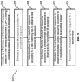
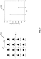
- FIG. 7 illustrates a constellation of 16 QAM (Quadrature Amplitude Modulation) and its corresponding demodulated log likelihood ratios (LLRs), in accordance with some embodiments of the present disclosure.
- QAM Quadrature Amplitude Modulation
- LLRs demodulated log likelihood ratios
- FIG. 8 illustrates a constellation of 64 QAM and its corresponding demodulated LLRs, in accordance with some embodiments of the present disclosure.
- FIG. 9 illustrates demodulated LLRs corresponding to a constellation of 256 QAM, in accordance with some embodiments of the present disclosure.
- FIG. 10 illustrates another exemplary interleaving scheme performed on LDPC coded bits, in accordance with some embodiments of the present disclosure.
- FIG. 11 illustrates an exemplary limited buffer rate matching scheme for LDPC code, in accordance with some embodiments of the present disclosure.
- FIG. 12 illustrates exemplary starting bit locations for redundancy versions RV0, RV1, RV2, in accordance with some embodiments of the present disclosure.
- FIG. 13 illustrates an exemplary starting bit location for redundancy version RV3, in accordance with some embodiments of the present disclosure.
- FIG. 14 illustrates exemplary starting bit locations for redundancy versions RV0, RV1, RV2, RV3, in accordance with some embodiments of the present disclosure.
- the present teaching discloses methods and apparatus for selecting starting bit location corresponding to each redundancy version (RV) and discloses a bit interleaving method to solve the problem of poor performance of quasi-cyclic LDPC coding under high order modulation or fading channels.
- RV redundancy version
- a parity check matrix H of the quasi-cyclic LDPC code is a matrix of M ⁇ Z rows and N ⁇ Z columns, which is composed of M ⁇ N sub-matrices.
- Each sub-matrix is a different power of the basic permutation matrix of size Z ⁇ Z. That is, each sub-matrix is obtained by cyclically shifting the unit matrix of size Z ⁇ Z by a number of values.
- the parity check matrix of the quasi-cyclic LDPC code can be described with the following mathematical formula:
- Z and power hb ij can uniquely identify each block matrix. If a block matrix is an all 0 matrix, it can be represented by “ ⁇ 1”, null, or other forms. If a block matrix is obtained by a cyclic shift s of the unit matrix, then it can be represented by s. All hb ij can form a quasi-cyclic LDPC-coded base matrix Hb, and the base matrix Hb of the LDPC code may be expressed as follows:
- Hb [ h ⁇ b 1 ⁇ 1 h ⁇ b l ⁇ 2 h ⁇ b 1 ⁇ 3 ⁇ L h ⁇ b l ⁇ N h ⁇ b 2 ⁇ 1 h ⁇ b 2 ⁇ 2 h ⁇ b 2 ⁇ 3 ⁇ L h ⁇ b 2 ⁇ N L L L L h ⁇ b M ⁇ ⁇ 1 h ⁇ b M ⁇ 2 h ⁇ b M ⁇ 3 ⁇ L h ⁇ b MN ] .
- the base matrix Hb contains two types of elements: elements that indicate the all-zero square matrices; and elements that indicate the sizes of cyclic shift relative to the unit matrix, which are generally expressed as integers between 0 and (Z ⁇ 1).
- the base matrix Hb may be referred to as a basic check matrix or a shift value matrix or a permutation value matrix.
- a quasi-cyclic LDPC-encoded template matrix (called base graph or BG) can be obtained.
- the base matrix Hb of the quasi-cyclic LDPC code can be determined according to the base graph of the quasi-cyclic LDPC code and a set of shift values (or coefficients).
- the dimension Z of the basic permutation matrix or the all-zero square matrix may be defined as a shift size, a lifting size, an expansion factor, or a sub-matrix size.
- the structured LDPC code can be uniquely determined by the base check matrix Hb and the lifting size Z.
- a base matrix Hb (2 rows and 4 columns) is shown as follows, where the corresponding lift size z is equal to 4.
- Hb [ 0 1 0 - 1 2 1 2 1 ]
- the corresponding base graph (BG) is:
- the parity check matrix H is obtained from the base matrix Hb and the lifting size Z, as follows:
- H includes [Hs Hp], where Hs is the system column partial matrix of the parity check matrix, and Hp is the check column partial matrix of the parity check matrix.
- C may include [Cs Cp], where Cs is the system bit sequence of the LDPC code (information bits, known bits), and Cp is the parity bit sequence (unknown bit) of the LDPC code.
- the quasi-cyclic LDPC coding sequence can be obtained as [Cs Cp].
- the quasi-cyclic LDPC coding sequence can also be calculated according to the cyclic shift of each Z-bit block.
- the present teaching discloses a method for selecting starting bit based on redundancy version (RV) in rate matching.
- RV redundancy version
- the starting bit locations may not be evenly distributed.
- One possible goal of selecting starting bit locations may be to avoid transmitting repetitive bits for different RVs.
- the present teaching also discloses a method for retransmission of LDPC coded data. After receiving a feedback signal indicating a retransmission is needed, the transmitting end may re-select a new starting bit location based on a scheme corresponding to a RV that is determined based on the feedback signal.
- the present teaching discloses an interleaving method to interleave the bit sequences after rate matching, e.g. based on block interleaving, where the number of rows of the block interleaver is equal to positive integer multiple of the modulation order.
- the block interleaver may also perform column permutations according to a predetermined column index sequence, to further mix information bits and parity bits and improve average transmission performance.
- the predetermined column index sequence has a length that is less than or equal to the number of columns of the block interleaver.
- the methods disclosed herein for processing quasi-cyclic LDPC coded data can be applied to a new radio access technology (NR) communication system, an LTE mobile communication system, a fifth generation (5G) mobile communication system, or other wireless/wired communication system.
- the methods may be applied to either downlink transmission (for the base station to transmit data to the mobile user) or uplink transmission (for the mobile user to transmit data to the base station).
- mobile users may refer to: mobile devices, access terminals, user terminals, subscriber stations, subscriber units, mobile stations, remote stations, remote terminals, user agents, user equipment, user devices, or some other terminology; and a base station may refer to: an access point (AP), a Node B, a radio network controller (RNC), an evolved Node B (eNB), a base station controller (BSC), a Base Transceiver Station (BTS), a Base Station (BS), a Transceiver Function (TF), a Radio Router, a Radio Transceiver, a Basic Service Unit, an Extended Service Unit, a radio base station (RBS), or some other terminology.
- RNC radio network controller
- eNB evolved Node B
- BSC base station controller
- BTS Base Transceiver Station
- BS Base Station
- TF Transceiver Function
- Radio Router a Radio Transceiver
- Basic Service Unit an Extended Service Unit
- RBS radio base station
- the quasi-cyclic LDPC coded data processing method disclosed in the present teaching can be applied to the following scenarios in a new radio access technology (new RAT): an Enhanced Mobile Broadband (eMBB) scenario, a Ultra-Reliable and Low Latency Communications (URLLC) scenario, or a massive machine type communication (mMTC) scenario.
- new RAT new radio access technology
- eMBB Enhanced Mobile Broadband
- URLLC Ultra-Reliable and Low Latency Communications
- mMTC massive machine type communication
- FIG. 1 illustrates an exemplary rate matching scheme 100 for LDPC code with a circular buffer 110 , in accordance with some embodiments of the present disclosure.
- the first 2Z bits of the LDPC encoded bits are not included in the circular buffer 110 .
- the circular buffer 110 includes a circular bit sequence that serves as a master bit sequence from which a to-be-transmitted bit sequence may be selected for transmission.
- the to-be-transmitted bit sequence is a sub-sequence of the master bit sequence and starts from a position corresponding to a current RV index. In this example, there are four RVs each of which has a fixed starting bit position in the circular buffer.
- RV0 corresponds to a starting bit position 0 of the master bit sequence; and the starting bit positions of the other three RVs (RV1, RV2 and RV3) are evenly distributed in the master bit sequence.
- RV0 is self-decodable, and the starting position of each RV is an integer multiple of Z. More types of selection of starting bit positions will be described later in the present teaching.
- FIG. 2 illustrates a block diagram of a communication node 200 , in accordance with some embodiments of the present disclosure.
- the communication node 200 is an example of a device that can be configured to implement the various methods described herein.
- the communication node 200 includes a housing 240 containing a system clock 202 , a processor 204 , a memory 206 , a transceiver 210 comprising a transmitter 212 and receiver 214 , a power module 208 , an LDPC encoder 220 , a block interleaver 222 , a rate matcher 224 , a bit interleaver 226 , a modulator 228 , and an LDPC decoder 229 .
- the system clock 202 provides the timing signals to the processor 204 for controlling the timing of all operations of the communication node 200 .
- the processor 204 controls the general operation of the communication node 200 and can include one or more processing circuits or modules such as a central processing unit (CPU) and/or any combination of general-purpose microprocessors, microcontrollers, digital signal processors (DSPs), field programmable gate array (FPGAs), programmable logic devices (PLDs), controllers, state machines, gated logic, discrete hardware components, dedicated hardware finite state machines, or any other suitable circuits, devices and/or structures that can perform calculations or other manipulations of data.
- CPU central processing unit
- DSPs digital signal processors
- FPGAs field programmable gate array
- PLDs programmable logic devices
- controllers state machines, gated logic, discrete hardware components, dedicated hardware finite state machines, or any other suitable circuits, devices and/or structures that can perform calculations or other manipulations of data.
- the memory 206 which can include both read-only memory (ROM) and random access memory (RAM), can provide instructions and data to the processor 204 .
- a portion of the memory 206 can also include non-volatile random access memory (NVRAM).
- the processor 204 typically performs logical and arithmetic operations based on program instructions stored within the memory 206 .
- the instructions (a.k.a., software) stored in the memory 206 can be executed by the processor 204 to perform the methods described herein.
- the processor 204 and memory 206 together form a processing system that stores and executes software.
- “software” means any type of instructions, whether referred to as software, firmware, middleware, microcode, etc. which can configure a machine or device to perform one or more desired functions or processes. Instructions can include code (e.g., in source code format, binary code format, executable code format, or any other suitable format of code). The instructions, when executed by the one or more processors, cause the processing system to perform the various functions described herein.
- the transceiver 210 which includes the transmitter 212 and receiver 214 , allows the communication node 200 to transmit and receive data to and from a remote device (e.g., the BS or another UE).
- An antenna 250 is typically attached to the housing 240 and electrically coupled to the transceiver 210 .
- the communication node 200 includes (not shown) multiple transmitters, multiple receivers, multiple transceivers, and/or multiple antennas.
- the transmitter 212 can be configured to wirelessly transmit packets having different packet types or functions, such packets being generated by the processor 204 .
- the receiver 214 is configured to receive packets having different packet types or functions
- the processor 204 is configured to process packets of a plurality of different packet types. For example, the processor 204 can be configured to determine the type of packet and to process the packet and/or fields of the packet accordingly.
- the 200 may be a base station or a mobile user in a wireless network.
- the 200 can serve as a transmitting end and/or a receiving end in a wireless communication.
- the LDPC encoder 220 can encode an information bit sequence based on an LDPC coding scheme to obtain an encoded bit sequence.
- the LDPC encoding may be based on a base matrix Hb and a lifting size Z.
- the information bit sequence includes information bits carrying original information the communication node 200 wants to transmit.
- the encoded bit sequence includes both information bits carrying the original information and parity bits for error correction.
- the 220 may send the encoded bit sequence, which may be referred as a codeword, to the rate matcher 224 for rate matching.
- the 224 in this example can perform rate matching to resize the codeword for transmission over the channel, in order to match a transmission rate consistent with the allocated transmission resources by the communication system.
- the 224 can generate a master bit sequence based on the encoded bit sequence.
- an exemplary master bit sequence may be obtained by removing some heading bits in the encoded bit sequence and storing the remaining bits into a circular buffer. It can be understood that a master bit sequence may also be generated according to other methods based on the encoded bit sequence.
- the master bit sequence serves as a master or mother LDPC codeword for the rate matcher 224 to select a portion of it for transmission according to the rate matching rule or the transmission rate requirement.
- the rate matcher 224 selects a subset of the master bit sequence to obtain a rate matched bit sequence, based on a redundancy version that is included in a set of redundancy versions.
- the 224 can send each rate matched bit sequence to the bit interleaver 226 and/or the block interleaver 222 for interleaving.
- the 226 may perform a bit-level interleaving on the rate matched bit sequence to enhance LDPC coding performance, especially for high order modulation.
- the bit interleaver 226 may interleave the rate matched bit sequence according to a predetermined index sequence to obtain a to-be-transmitted bit sequence.
- the block interleaver 222 may determine the predetermined index sequence for the bit interleaver 226 based on a matrix having R subblock number of rows.
- R subblock is chosen to be a positive integer multiple of the modulation order.
- R subblock may be 16, 32, 48, 64, etc. for a 16 QAM modulation.
- the block interleaver 222 may perform column permutations on the matrix before the to-be-transmitted bit sequence is obtained.
- the column permutations may be performed according to a predetermined column index sequence.
- the predetermined column index sequence has a length that is less than or equal to the number of columns of the matrix of the block interleaver 222 .
- the 226 or the block interleaver 222 may send the to-be-transmitted bit sequence after interleaving to the modulator 228 for modulation and transmission.
- the 228 can modulate the to-be-transmitted bit sequence to obtain a modulated symbol sequence according to a modulation order that is a positive integer, e.g. 16 QAM, 64 QAM, 256 QAM, etc.
- the 228 then transmits, via the transmitter 212 , the modulated symbol sequence to another communication node that serves as a receiving end.
- the modulator 228 can receive, via the receiver 214 , a modulated symbol sequence from another communication node that serves as a transmitting end.
- the modulator 228 may demodulate the modulated symbol sequence according to the modulation order to obtain a bit sequence, and send the bit sequence to the LDPC decoder 229 for decoding.
- the communication node 200 further includes a separate demodulator (not shown) for demodulating the modulated symbol sequence according to the modulation order to obtain a bit sequence, and send the bit sequence to the LDPC decoder 229 for decoding.
- the 229 may try to decode the bit sequence based on the LDPC coding scheme to obtain the original information bits sent by the transmitting end.
- the LDPC decoder 229 can determine whether there is transmission error of the modulated symbol sequence, e.g. based on the parity bits in the bit sequence.
- the LDPC decoder 229 may generate a feedback signal associated with the bit sequence.
- the feedback signal may indicate an acknowledgement (ACK), a negative acknowledgement (NACK), or a discontinuous transmission (DTX).
- ACK acknowledgement
- NACK negative acknowledgement
- DTX discontinuous transmission
- the 229 can transmit, via the transmitter 212 , the feedback signal to the transmitting end.
- the rate matcher 224 may receive, via the receiver 214 , the feedback signal, associated with a previously transmitted bit sequence, from the receiving end.
- the rate matcher 224 may reselect a subset of the master bit sequence based on a scheme corresponding to a RV that is determined based on the feedback signal. Then, the rate matcher 224 can send the reselected bit sequence, that is rate matched, to the bit interleaver 226 for bit interleaving.
- the modulator 228 can perform modulation and retransmission, via the transmitter 212 , to the receiving end.
- the power module 208 can include a power source such as one or more batteries, and a power regulator, to provide regulated power to each of the above-described modules in FIG. 2 .
- a power source such as one or more batteries
- a power regulator to provide regulated power to each of the above-described modules in FIG. 2 .
- the power module 208 can include a transformer and a power regulator.
- the various modules discussed above are coupled together by a bus system 230 .
- the bus system 230 can include a data bus and, for example, a power bus, a control signal bus, and/or a status signal bus in addition to the data bus. It is understood that the modules of the communication node 200 can be operatively coupled to one another using any suitable techniques and mediums.
- FIG. 2 Although a number of separate modules or components are illustrated in FIG. 2 , persons of ordinary skill in the art will understand that one or more of the modules can be combined or commonly implemented.
- the processor 204 can implement not only the functionality described above with respect to the processor 204 , but also implement the functionality described above with respect to the LDPC encoder 220 .
- each of the modules illustrated in FIG. 2 can be implemented using a plurality of separate components or elements.
- FIG. 3 illustrates a flow chart for a method 300 performed by a communication node, e.g. the communication node 200 as shown in FIG. 2 , for transmitting data encoded by LDPC, in accordance with some embodiments of the present disclosure.
- a communication node referred to as the first node, encodes an information bit sequence based on an LDPC coding scheme to obtain an encoded bit sequence.
- the first node generates at 304 a master bit sequence based on the encoded bit sequence.
- the first node selects at 306 a subset of the master bit sequence according to a rate matching rule to obtain a rate matched bit sequence.
- the first node interleaves the rate matched bit sequence according to a predetermined index sequence to obtain a to-be-transmitted bit sequence.
- the first node then modulates at 310 the to-be-transmitted bit sequence to obtain a modulated symbol sequence according to a modulation order that is a positive integer.
- the first node transmits at 312 the modulated symbol sequence to a second node.
- FIG. 4 illustrates a flow chart for a method 400 performed by a communication node e.g. the communication node 200 as shown in FIG. 2 , for retransmitting data encoded by LDPC, in accordance with some embodiments of the present disclosure.
- the first node receives a feedback signal associated with the to-be-transmitted bit sequence from the second node.
- the first node reselects at 404 a subset of the master bit sequence based on a scheme corresponding to a redundancy version determined based on the feedback signal.
- the first node interleaves at 406 the reselected subset according to the predetermined index sequence to obtain a to-be-retransmitted bit sequence.
- the first node transmits at 408 the to-be-retransmitted bit sequence to the second node.
- FIG. 5 illustrates a flow chart for a method 500 performed by a communication node e.g. the communication node 200 as shown in FIG. 2 , for receiving and decoding data encoded by LDPC, in accordance with some embodiments of the present disclosure.
- a communication node referred to as the second node
- receives the modulated symbol sequence from the first node demodulates at 504 the modulated symbol sequence according to the modulation order to obtain a bit sequence.
- the second node decodes at 506 the bit sequence based on the LDPC coding scheme.
- the second node generates at 508 a feedback signal associated with the bit sequence based on the decoding.
- the second node transmits at 510 the feedback signal to the first node.
- a method performed by a first node is disclosed.
- An information bit sequence is encoded based on an LDPC coding scheme to obtain an encoded bit sequence.
- the information bit sequence is encoded based on a base matrix Hb and a lifting size Z.
- the first node then generates a master bit sequence based on the encoded bit sequence.
- the master bit sequence includes Ncb bits ( 0 to Ncb ⁇ 1) that are selected from bits 2 *Z to 2 *Z+Ncb ⁇ 1 in the encoded bit sequence.
- the first node selects a subset of the master bit sequence according to a rate matching rule to obtain a rate matched bit sequence.
- the subset of the master bit sequence is selected based on a redundancy version that is included in a set of redundancy versions comprising at least (RV0, RV1, RV2, and RV3).
- the first node interleaves the rate matched bit sequence according to a predetermined index sequence to obtain a to-be-transmitted bit sequence; and transmits the to-be-transmitted bit sequence to a second node.
- the first node modulates the to-be-transmitted bit sequence to obtain a modulated symbol sequence according to a modulation order that is a positive integer; and transmits the modulated symbol sequence to the second node.
- the predetermined index sequence is determined based on a block interleaver that has R subblock number of rows, where R subblock is a positive integer multiple of the modulation order.
- the to-be-transmitted bit sequence is obtained based on column permutations performed by the block interleaver according to a predetermined column index sequence.
- the rate matched bit sequence is obtained based on at least one of the following schemes, each of which corresponds to at least one of the redundancy versions in the set of redundancy versions: scheme 1: selecting a sub-sequence starting from bit 0 in the master bit sequence; scheme 2: selecting a sub-sequence starting from bit (function( ⁇ Ncb/( ⁇ 3 ⁇ Z))+ ⁇ ) ⁇ Z in the master bit sequence, wherein a is a positive real number, ⁇ is a positive real number, ⁇ is an integer greater than ⁇ 10 and less than 10, and function ( ⁇ ) means taking a closest upper integer, taking a closest lower integer, or taking an integer by rounding; scheme 3: selecting a sub-sequence starting from bit (function( ⁇ Ncb/( ⁇ 3 ⁇ Z)) ⁇ 2+ ⁇ ) ⁇ Z in the master bit sequence; scheme 4: selecting a sub-sequence starting from bit Ncb ⁇ x0 in the master bit sequence, wherein x0 is a positive integer less than
- the set of redundancy versions comprise at least four redundancy versions (RV0, RV1, RV2, and RV3) and at most two of the redundancy versions RV1, RV2, and RV3 correspond to the scheme 6.
- RV0, RV1, RV2, and RV3 correspond to the scheme 6
- the two redundancy versions correspond to two different values of x2.
- at least one of the redundancy versions RV1, RV2, and RV3 correspond to at least one of the scheme 2 and the scheme 3.
- the redundancy version RV0 corresponds to the scheme 1; the redundancy version RV1 corresponds to at least one of the scheme 2, the scheme 5, and the scheme 7; the redundancy version RV2 corresponds to the scheme 3; and the redundancy version RV3 corresponds to at least one of the scheme 4 and the scheme 6.
- a transmitting end may retransmit data when either one of the two states happens: a NACK state and a DTX state.
- the NACK state means the transmitting end is sure that the receiving end has received the data but the receiving end did not decode correctly. As such, the transmitting end may retransmit more parity bits to obtain performance gain for the NACK state.
- the DTX state means that the transmitting end is not sure whether the receiving end has received the data or not.
- the transmitting end can retransmit the data of RV0. But in case that the receiving end has received the data but there was decoding error, retransmission of the data of other redundancy versions will provide more performance gain. Therefore, for DTX state, it is better for one of the redundancy versions to be defined with a self-decodable feature.
- a self-decodable RV can satisfactorily solve the problem of the DTX state.
- at least one of [RV1, RV2, RV3] is self-decodable and contains additional parity bits that are not in RV0.
- the first node receives a NACK signal associated with the to-be-transmitted bit sequence from the second node; reselects a subset of the master bit sequence based on a scheme corresponding to at least one of the redundancy version RV1 and the redundancy version RV2; interleaves the reselected subset according to the predetermined index sequence to obtain a to-be-retransmitted bit sequence; and transmits the to-be-retransmitted bit sequence to the second node.
- the redundancy versions RV1 and RV2 here can carry more parity bits, with a smaller effective code rate for retransmission data, to achieve performance gain for the retransmission. But the redundancy versions RV1 and RV2 may not be self-decodable.
- the first node receives a DTX signal associated with the to-be-transmitted bit sequence from the second node; reselects a subset of the master bit sequence based on a scheme corresponding to at least one of the redundancy version RV0 and the redundancy version RV3; interleaves the reselected subset according to the predetermined index sequence to obtain a to-be-retransmitted bit sequence; and transmits the to-be-retransmitted bit sequence to the second node.
- the redundancy versions RV0 and RV3 here are self-decodable, such that the receiving end can directly decode the retransmitted data without receiving the previously transmitted data.
- the information bit sequence is encoded based on a quasi-cyclic LDPC code
- the parity check matrix in the quasi-cyclic LDPC code has two types of base graphs: base graph 1 (BG1) and base graph 2 (BG2).
- the BG1 includes 46 rows and 68 columns; and the BG2 includes 42 rows and 52 columns.
- Table 1 shows the “1” positions corresponding to the row index of i, in the base graph matrices (BG1 and BG2). That is, the “1” positions can be replaced by a cyclic permutation unit matrix.
- the first column corresponds to an indication of the row index i of the BG1 and the BG2;
- the second column corresponds to an indication of the column index j of the BG1, where the combination of i and j [i, j] determines the “1” position of the BG1;
- the third column corresponds to an indication of column index j of the BG2, where the combination of i and j [i,j] determines the “1” position of the BG2.
- Table 2 and Table 3 respectively illustrate the eight shift value matrices corresponding to the BG1, and the eight shift value matrices corresponding to the BG2, where i is used to indicate the row index, j is used to indicate the column index, and is the index number corresponding to the set of lifting sizes.
- Table 4 corresponds to the lifting sizes supported by the BG1 and the BG2, including eight sets of lifting sizes, where the index numbers of the eight sets of lifting sizes are in the order of 0 to 7.
- a base graph matrix can be determined based on the length information of the information packet and the rate information of the quasi-cyclic LDPC code.
- the BG2 is selected; otherwise, the BG1 is selected.
- redundancy version set ⁇ RV0, RV1, RV2, RV3 ⁇
- the redundancy version is an element of the redundancy version set.
- the starting bit index is A1 ⁇ Z, wherein A1 is equal to kb0 ⁇ 1, kb0, kb0+1, kb0+2, Kb0+3, kb0+4, or kb0+5, where kb0 is the number of system columns of the base matrix.
- R max there is a code rate threshold R max, such that in the redundant version set, for the bit selection corresponding to the redundancy version RV1, the starting bit index is A1 ⁇ Z, wherein A1 is determined by the code rate threshold R max.
- R max may be a real number greater than 0.4 and less than 1.
- the A1 is equal to function( ⁇ kb/R max)+2+ ⁇ , wherein kb is a positive integer less than or equal to the number of system columns of the base matrix, a is a real number greater than 0, 8 is an integer greater than ⁇ 10 and less than 10, function( ⁇ ) means taking a closest upper integer, taking a closest lower integer, or taking an integer by rounding.
- the base graph matrix of the base matrix is BG1, and the code rate threshold R max is a real number greater than or equal to 8/9 and less than 1; or the base graph matrix of the base matrix is BG2, and the code rate threshold R max is a real number greater than or equal to 2 ⁇ 3 and less than 1.
- the starting bit indices are A2 ⁇ Z and A3 ⁇ Z, respectively, wherein the specific values of the A2 and A3 are determined according to A1 and nb0, where nb0 is a positive integer less than or equal to the total number of columns of the base matrix.
- the A2 is equal to A1+function( ⁇ (nb0 ⁇ 2)/( ⁇ 3))+ ⁇
- A3 is equal to A1+function( ⁇ (nb0 ⁇ 2)/( ⁇ 3)) ⁇ 2+ ⁇
- ⁇ is a real number greater than
- ⁇ is a real number greater than
- ⁇ is an integer greater than ⁇ 10 and less than
- function( ⁇ ) means taking a closest upper integer, taking a closest lower integer, or taking an integer by rounding.
- the starting bit indices are A1 ⁇ Z and A2 ⁇ Z, respectively, wherein the specific values of the A1 and A2 are determined according to nb0, where nb0 is a positive integer less than or equal to the total number of columns of the base matrix.
- the A1 is equal to function( ⁇ (nb0 ⁇ 2)/( ⁇ 3))+ ⁇
- the A2 is equal to function( ⁇ (nb0 ⁇ 2)/( ⁇ 3)) ⁇ 2+ ⁇ .
- nb0 68
- the starting bit index is A3 ⁇ Z, wherein A3 is equal to nb0 ⁇ B, where the nb0 is a positive integer less than or equal to the total number of columns in the base matrix, B is a positive integer less than nb0/4.
- nb0 a positive integer less than or equal to the total number of columns in the base matrix
- B is a positive integer less than nb0/4.
- the starting bit indices are A0 ⁇ Z, A1 ⁇ Z, A2 ⁇ Z and A3 ⁇ Z, respectively.
- the starting bit indices are function(nb1/(nb ⁇ 2) ⁇ A0) ⁇ Z, function(nb1/(nb ⁇ 2) ⁇ A1) ⁇ Z, function(nb1/(nb ⁇ 2) ⁇ A2) ⁇ Z and function(nb1/(nb ⁇ 2) ⁇ A3) ⁇ Z, respectively, where the nb is a positive integer equal to the total number of columns in the base matrix, and nb1 is a positive integer less than nb ⁇ 2.
- the bit selection is performed in a scaling down manner to determine a starting bit index for each redundant version of the limited circular buffer.
- the operation is simple and convenient.
- the nb1 is smaller than nb ⁇ 2, indicating that the cyclic cache is limited and cannot completely store the LDPC codeword sequence. This can be used in some low-power or low-complexity devices, and in some high-throughput devices as well.
- the redundancy version of the sequence to be transmitted for the first transmission is RV0 and the redundancy version of the first retransmission is determined according to the code rate R, which is a real number greater than 0 and less than 1.
- the first retransmission means that it is necessary to retransmit the data corresponding to the information packet bit sequence for the first time when the sequence to be transmitted is not correctly decoded at the first transmission. If the first retransmission data cannot be decoded correctly, it is necessary to perform a second retransmission. If there is still a decoding error, even a third retransmission is required.
- the code rate R is a value obtained by dividing the length of the information packet bit sequence by the length of the bit sequence to be transmitted, or the code rate R is determined by a modulation coding scheme index.
- the preset code rate range 1 corresponds to the redundancy version value RV2 or RV3 of a retransmission
- the preset code rate range 2 corresponds to the redundancy version value RV1 of a retransmission.
- the R0 is a real number greater than 0 and less than 1.
- R0 when the base graph matrix of the base matrix is BG1, then R0 is a real number greater than or equal to 1 ⁇ 2 and less than or equal to 3 ⁇ 4; and when the base graph matrix of the base matrix is BG2, then R0 is a real number greater than or equal to 1 ⁇ 3 and less than or equal to 1 ⁇ 2.
- a preset code rate range 1 including code rate greater than 0 and less than R0 a preset code rate range 2 including code rate greater than or equal to R0 and less than R1
- the preset code rate range 1 corresponds to the redundancy version value RV3 of a retransmission
- the preset code rate range 2 corresponds to the redundancy version value RV2 of a retransmission
- the preset code rate range 3 corresponds to the redundancy version value RV1 of a retransmission.
- Each of the R0 and R1 is a real number greater than 0 and less than 1, and R0 is less than R1.
- R0 when the base graph matrix of the base matrix is BG1, then R0 is a real number less than or equal to 1 ⁇ 2 and greater than 0, R1 is a real number greater than 1 ⁇ 2 and less than 1; and when the base graph matrix of the base matrix is BG2, then R0 is a real number less than or equal to 1 ⁇ 3 and greater than 0, R1 is a real number greater than 1 ⁇ 3 and less than 1.
- the R0 is determined on the basis of kb1 and A3, and the R1 is determined based on kb1 and A2, wherein the kb1 is a positive integer less than or equal to the number of system columns of the base matrix.
- the R0 is equal to kb1/A3 ⁇
- the R1 is equal to kb1/A2 ⁇
- each of ⁇ and ⁇ is a real number greater than zero.
- the redundancy version of the bit sequence to be transmitted in the first transmission is RV0 and the redundancy version value of the first retransmission is determined based on the length and the lifting size of bit sequence to be transmitted in the first transmission.
- each of the preset integer ranges corresponding to a redundancy version value of a retransmission.
- a preset integer range 1 including integers greater than 0 and less than C0
- a preset integer range 2 including integers greater than or equal to C0 and less than C1
- a preset integer range 3 including integers greater than or equal to C1 and less than C.
- the preset integer range 1 corresponds to the redundancy version value RV1 of a retransmission
- the preset integer range 2 corresponds to the redundancy version value RV2 of a retransmission
- the preset integer range 3 corresponds to the redundancy version value RV3 of a retransmission.
- the C0, C1, and C are positive integers, and C0 is less than C1, both C0 and C1 are less than C.
- the C is equal to nb2-2, wherein the nb2 is a positive integer less than or equal to the total number of columns of the base matrix.
- nb2 is a positive integer less than or equal to the total number of columns of the base matrix.
- C0 is an integer greater than 27 or less than 37
- C1 is an integer greater than 44 or less than 53
- C is equal to 66
- C0 is an integer greater than 19 or less than 29
- C1 is an integer greater than 30 or less than 42
- C is equal to 50.
- the rate matched bit sequence is interleaved according to a predetermined index number sequence to obtain a bit sequence to be transmitted corresponding to the redundancy version index.
- Bit-level interleaving can be used by LDPC code to improve high code rate performance and/or to counter burst error.
- An exemplary interleaving for BG1 is shown in FIG. 6 , where one LDPC codeword 610 is organized into 66 units, and each unit contains Z bits. Then an interleaving among these units is performed before writing the interleaved codeword 620 into a circular buffer.
- the bit sequence before interleaving is: x 0 , x 1 , x 2 , . . . , x N-1
- the bit sequence after interleaving is: y 0 , y 1 , y 2 , . . . , y N-15
- the predetermined index number sequence is obtained according to a block interleaver, wherein the number of rows of the block interleaver is R subblock .
- One can determine the number of columns of the block interleaver is C subblock based on the length N of the rate matched bit sequence and the R subblock .
- the C subblock is the smallest integer that satisfies N ⁇ (R subblock ⁇ C subblock ).
- the block interleaver is in a “row-in column-out” manner. When N ⁇ (R subblock ⁇ C subblock ) it is necessary to fill (R subblock ⁇ C subblock ) ⁇ N bits in the last row.
- the column permutation is also performed and then the interleaved bit sequence is read out in the order of the columns.
- the number of rows R subblock of the block interleaver is a positive integer multiple of the modulation order, wherein the modulation order is an integer greater than zero.
- the modulation order refers to the number of bits carried by the constellation modulation symbol.
- the constellation symbol modulation includes: BPSK, QPSK, 16 QAM, 64 QAM and 256 QAM, and their corresponding modulation orders (the number of bits carried by each constellation symbol) are: 1, 2, 4, 6 and 8, respectively.
- the block interleaver also performs column permutations according to a sequence of the predetermined column index numbers, the length of the predetermined column index sequence being less than or equal to the number of columns of the block interleaver.
- a constellation symbol In a QAM modulation, a constellation symbol consists of an in-phase signal and a quadrature signal. According to the orthogonality of the two signals, a constellation symbol can carry two parallel data (I and Q). For example, 4 QAM carries 2 bits, 16 QAM carries 4 bits, 64 QAM carries 6 bits, and 256 QAM carries 8 bits, and so on.
- Constellation diagrams 710 , 810 of high order modulation (i.e. modulation order ⁇ 16) of 16 QAM and 64 QAM are shown in FIG. 7 and FIG. 8 , respectively.
- the normalized amplitude of demodulated LLRs 720 with 4 bits for 16 QAM are also depicted.
- the LLRs for 16 QAM can be divided into two groups: first 2 LLRs with larger amplitude and the remaining 2 LLRs with smaller amplitude.
- three different amplitude groups can be observed in demodulated LLRs 820 of 64 QAM as shown in FIG. 8 .
- the value of LLRs amplitude indicates a confidence degree or reliability. The larger LLRs amplitude is, the more reliable the LLR is. Therefore, the amplitude of demodulated LLRs for high order modulation has inherent variation even in AWGN channel. This unequal bit reliability of high order modulation may impair the performance for LDPC code.
- the 8 mapped bits 920 of 256 QAM can be divided into 4 groups: group-1 including the 1 st and the 2 nd bit, group-2 including the 3 rd and the 4 th bit, group-3 including the 5 th and the 6 th bit, and group-4 including the 7 th and the 8 th bit.
- group-1 including the 1 st and the 2 nd bit
- group-2 including the 3 rd and the 4 th bit
- group-3 including the 5 th and the 6 th bit
- group-4 including the 7 th and the 8 th bit.
- the demodulated LLR for group-1 has largest amplitude with highest reliability
- group-2 has the second highest reliability
- group-3 has the third reliability
- group-4 has the least reliability.
- the LDPC coded bits 1010 are divided into 4 groups.
- the bits in 1 st group are mapped in group-1 for all 256 QAM constellation symbols.
- bits in 2 nd group are mapped in group-2
- bits in 3 rd group are mapped in group-3
- bits in 4 th group are mapped in group-4.
- Limited buffer rate matching may be supported for NR-LDPC.
- LBRM buffer rate matching
- the size of the circular buffer can be set small.
- the starting bit locations for [RV0, RV1, RV2] are defined as shown in FIG. 12 .
- An LDPC codeword 1210 has a natural order in the circular buffer.
- the LDPC codeword in the circular buffer includes Ncb bits ( 0 to Ncb ⁇ 1) that are selected from bits 2 *Z to 2 *Z+Ncb ⁇ 1 in the mother LDPC codeword.
- the retransmission data is selected from an interleaved LDPC codeword 1310 , as shown in FIG. 13 .
- the interleaved LDPC codeword 1310 in the circular buffer includes Ncb bits ( 0 to Ncb ⁇ 1) that are selected from bits 2 *Z to 2 *Z+Ncb ⁇ 1 in the interleaved mother LDPC codeword.
- a block interleaving scheme with Z columns can be used to generate the interleaved mother LDPC codeword to make data corresponding to RV3 self-decodable.
- the starting bit location design for [RV0, RV1, RV2] is the same as that in the first embodiment; and the starting bit location for the RV3 is set near the end of the LDPC codeword 1410 .
- the LDPC codeword 1410 has a natural order.
- the starting bit location of RV3 is equal to 56 ⁇ Z for BG1 and is equal to 43 ⁇ Z for BG2.
- any reference to an element herein using a designation such as “first,” “second,” and so forth does not generally limit the quantity or order of those elements. Rather, these designations can be used herein as a convenient means of distinguishing between two or more elements or instances of an element. Thus, a reference to first and second elements does not mean that only two elements can be employed, or that the first element must precede the second element in some manner.
- any of the various illustrative logical blocks, modules, processors, means, circuits, methods and functions described in connection with the aspects disclosed herein can be implemented by electronic hardware (e.g., a digital implementation, an analog implementation, or a combination of the two), firmware, various forms of program or design code incorporating instructions (which can be referred to herein, for convenience, as “software” or a “software module), or any combination of these techniques.
- a processor, device, component, circuit, structure, machine, module, etc. can be configured to perform one or more of the functions described herein.
- IC integrated circuit
- DSP digital signal processor
- ASIC application specific integrated circuit
- FPGA field programmable gate array
- the logical blocks, modules, and circuits can further include antennas and/or transceivers to communicate with various components within the network or within the device.
- a general purpose processor can be a microprocessor, but in the alternative, the processor can be any conventional processor, controller, or state machine.
- a processor can also be implemented as a combination of computing devices, e.g., a combination of a DSP and a microprocessor, a plurality of microprocessors, one or more microprocessors in conjunction with a DSP core, or any other suitable configuration to perform the functions described herein.
- Computer-readable media includes both computer storage media and communication media including any medium that can be enabled to transfer a computer program or code from one place to another.
- a storage media can be any available media that can be accessed by a computer.
- such computer-readable media can include RAM, ROM, EEPROM, CD-ROM or other optical disk storage, magnetic disk storage or other magnetic storage devices, or any other medium that can be used to store desired program code in the form of instructions or data structures and that can be accessed by a computer.
- module refers to software, firmware, hardware, and any combination of these elements for performing the associated functions described herein. Additionally, for purpose of discussion, the various modules are described as discrete modules; however, as would be apparent to one of ordinary skill in the art, two or more modules may be combined to form a single module that performs the associated functions according embodiments of the present disclosure.
- memory or other storage may be employed in embodiments of the present disclosure.
- memory or other storage may be employed in embodiments of the present disclosure.
- any suitable distribution of functionality between different functional units, processing logic elements or domains may be used without detracting from the present disclosure.
- functionality illustrated to be performed by separate processing logic elements, or controllers may be performed by the same processing logic element, or controller.
- references to specific functional units are only references to a suitable means for providing the described functionality, rather than indicative of a strict logical or physical structure or organization.
Landscapes
- Engineering & Computer Science (AREA)
- Physics & Mathematics (AREA)
- Computer Networks & Wireless Communication (AREA)
- Signal Processing (AREA)
- Probability & Statistics with Applications (AREA)
- Theoretical Computer Science (AREA)
- Mathematical Physics (AREA)
- Error Detection And Correction (AREA)
- Detection And Prevention Of Errors In Transmission (AREA)
Priority Applications (1)
| Application Number | Priority Date | Filing Date | Title |
|---|---|---|---|
| US17/566,846 US11728830B2 (en) | 2017-09-11 | 2021-12-31 | Methods and apparatus for processing LDPC coded data |
Applications Claiming Priority (1)
| Application Number | Priority Date | Filing Date | Title |
|---|---|---|---|
| PCT/CN2017/101278 WO2019047230A1 (en) | 2017-09-11 | 2017-09-11 | METHOD AND APPARATUS FOR PROCESSING LOW DENSITY PARITY CONTROL CODED DATA |
Related Parent Applications (1)
| Application Number | Title | Priority Date | Filing Date |
|---|---|---|---|
| PCT/CN2017/101278 Continuation WO2019047230A1 (en) | 2017-09-11 | 2017-09-11 | METHOD AND APPARATUS FOR PROCESSING LOW DENSITY PARITY CONTROL CODED DATA |
Related Child Applications (1)
| Application Number | Title | Priority Date | Filing Date |
|---|---|---|---|
| US17/566,846 Continuation US11728830B2 (en) | 2017-09-11 | 2021-12-31 | Methods and apparatus for processing LDPC coded data |
Publications (2)
| Publication Number | Publication Date |
|---|---|
| US20200212937A1 US20200212937A1 (en) | 2020-07-02 |
| US11233531B2 true US11233531B2 (en) | 2022-01-25 |
Family
ID=65634605
Family Applications (2)
| Application Number | Title | Priority Date | Filing Date |
|---|---|---|---|
| US16/790,046 Active US11233531B2 (en) | 2017-09-11 | 2020-02-13 | Methods and apparatus for processing LDPC coded data |
| US17/566,846 Active US11728830B2 (en) | 2017-09-11 | 2021-12-31 | Methods and apparatus for processing LDPC coded data |
Family Applications After (1)
| Application Number | Title | Priority Date | Filing Date |
|---|---|---|---|
| US17/566,846 Active US11728830B2 (en) | 2017-09-11 | 2021-12-31 | Methods and apparatus for processing LDPC coded data |
Country Status (7)
| Country | Link |
|---|---|
| US (2) | US11233531B2 (zh) |
| EP (1) | EP3682546A4 (zh) |
| JP (2) | JP7464521B2 (zh) |
| KR (1) | KR102450664B1 (zh) |
| CN (2) | CN116054843A (zh) |
| CA (1) | CA3073980C (zh) |
| WO (1) | WO2019047230A1 (zh) |
Families Citing this family (11)
| Publication number | Priority date | Publication date | Assignee | Title |
|---|---|---|---|---|
| CN111741311B (zh) | 2014-10-31 | 2024-04-02 | 三星电子株式会社 | 用于对运动矢量进行编码/解码的方法和装置 |
| JP2019165269A (ja) * | 2016-07-28 | 2019-09-26 | シャープ株式会社 | 基地局装置、端末装置および通信方法 |
| CN112994844B (zh) * | 2017-06-23 | 2023-02-14 | 华为技术有限公司 | 一种信道编码方法、数据接收方法及相关设备 |
| WO2019090468A1 (en) * | 2017-11-07 | 2019-05-16 | Qualcomm Incorporated | Methods and apparatus for crc concatenated polar encoding |
| WO2021214788A1 (en) * | 2020-04-21 | 2021-10-28 | Khitish Chandra Behera | Method and system for efficient low latency rate-matching and bit-interleaving for 5g nr |
| EP4226537A1 (en) * | 2020-10-09 | 2023-08-16 | Qualcomm Incorporated | Starting bit determination for pusch repetition with transport block size scaling |
| CN112653473B (zh) * | 2020-12-11 | 2021-08-13 | 天津大学 | 一种基于渐进弦边增长的非二进制ldpc码优化方法 |
| KR20230037264A (ko) * | 2021-09-09 | 2023-03-16 | 삼성전자주식회사 | 통신 시스템에서 신호 송수신 방법 및 장치 |
| WO2023057046A1 (en) * | 2021-10-05 | 2023-04-13 | Nokia Technologies Oy | Reduced complexity ldpc encoding |
| CN116318552B (zh) * | 2023-03-15 | 2023-09-22 | 归芯科技(深圳)有限公司 | Turbo码的交织或解交织方法及其器件、通信芯片和装置 |
| CN117081607B (zh) * | 2023-08-30 | 2024-03-19 | 白盒子(上海)微电子科技有限公司 | 一种nr ldpc部分校验矩阵编译码指示信息获取方法 |
Citations (17)
| Publication number | Priority date | Publication date | Assignee | Title |
|---|---|---|---|---|
| US20040153934A1 (en) | 2002-08-20 | 2004-08-05 | Hui Jin | Methods and apparatus for encoding LDPC codes |
| CN101005334A (zh) | 2007-01-12 | 2007-07-25 | 中兴通讯股份有限公司 | 一种低密度奇偶校验码的混合自动请求重传包生成方法 |
| CN101188428A (zh) | 2007-12-10 | 2008-05-28 | 中兴通讯股份有限公司 | 一种ldpc码的有限长度循环缓存的速率匹配方法 |
| CN101277118A (zh) | 2007-03-28 | 2008-10-01 | 北京三星通信技术研究有限公司 | 基于ldpc码的级联码的编码方法 |
| CN101489135A (zh) | 2009-01-22 | 2009-07-22 | 航天恒星科技有限公司 | 一种方便ldpc长码在fpga实现的编码器及编码方法 |
| US20090304111A1 (en) | 2005-09-13 | 2009-12-10 | Osamu Shinya | Decoding Device and Method |
| CN101867443A (zh) | 2009-04-14 | 2010-10-20 | 中兴通讯股份有限公司 | 速率匹配方法和装置 |
| US20120320880A1 (en) | 2010-01-17 | 2012-12-20 | Lg Electronics Inc. | Method and apparatus for transmitting control information in a wireless communication system |
| CN103597748A (zh) | 2011-06-16 | 2014-02-19 | 松下电器产业株式会社 | 发送处理方法、发送机、接收处理方法和接收机 |
| CN107026709A (zh) | 2016-02-01 | 2017-08-08 | 中兴通讯股份有限公司 | 一种数据包编码处理方法及装置、基站及用户设备 |
| WO2018144560A1 (en) | 2017-02-03 | 2018-08-09 | Idac Holdings, Inc. | Code block segmentation depending on ldpc base matrix selection |
| WO2018171043A1 (zh) | 2017-03-24 | 2018-09-27 | 中兴通讯股份有限公司 | 一种准循环低密度奇偶校验编码处理方法及装置 |
| CN109120374A (zh) | 2017-06-26 | 2019-01-01 | 中兴通讯股份有限公司 | 准循环低密度奇偶校验编码设计方法及装置 |
| WO2019029309A1 (zh) | 2017-08-11 | 2019-02-14 | 中兴通讯股份有限公司 | 数据编码方法、装置、存储介质及处理器 |
| US20190356341A1 (en) * | 2017-02-06 | 2019-11-21 | Huawei Technologies Co., Ltd. | Data processing method and device |
| US20200162196A1 (en) * | 2017-03-22 | 2020-05-21 | Samsung Electronics Co., Ltd. | Apparatus and method of transmission using harq in communication or broadcasting system |
| US10735134B2 (en) * | 2017-08-11 | 2020-08-04 | Qualcomm Incorporated | Self-decodable redundancy versions for low-density parity-check codes |
Family Cites Families (12)
| Publication number | Priority date | Publication date | Assignee | Title |
|---|---|---|---|---|
| US6029264A (en) * | 1997-04-28 | 2000-02-22 | The Trustees Of Princeton University | System and method for error correcting a received data stream in a concatenated system |
| DE60114849T2 (de) * | 2001-11-16 | 2006-04-20 | Matsushita Electric Industrial Co., Ltd., Kadoma | ARQ Sendewiederholung mit Anforderungswiederholungs-Schema das mehrere Redundanz-Versionen verwendet und Empfänger/Sender dafür |
| US7139964B2 (en) * | 2002-05-31 | 2006-11-21 | Broadcom Corporation | Variable modulation with LDPC (low density parity check) coding |
| US7346832B2 (en) * | 2004-07-21 | 2008-03-18 | Qualcomm Incorporated | LDPC encoding methods and apparatus |
| CN101350695B (zh) * | 2007-07-20 | 2012-11-21 | 电子科技大学 | 低密度奇偶校验码译码方法及系统 |
| US7865813B2 (en) * | 2007-07-30 | 2011-01-04 | Marvell International Ltd. | Rate matching for a wireless communications systems |
| US8781006B2 (en) * | 2010-05-21 | 2014-07-15 | Qualcomm Incorporated | Link adaptation in multi-carrier communication systems |
| US10541781B2 (en) | 2016-01-29 | 2020-01-21 | Intel IP Corporation | Rate matching using low-density parity-check codes |
| US10523386B2 (en) * | 2016-06-24 | 2019-12-31 | Lg Electronics Inc. | Method of processing data block in wireless communication system and apparatus therefor |
| ES2787907T3 (es) | 2016-08-12 | 2020-10-19 | Ericsson Telefon Ab L M | Métodos de adaptación de velocidad para códigos LDPC |
| US10804933B2 (en) | 2016-09-30 | 2020-10-13 | Lg Electronics Inc. | QC LDPC code rate matching method and device therefor |
| WO2018169339A1 (ko) | 2017-03-16 | 2018-09-20 | 엘지전자 주식회사 | 채널 코딩을 수행하는 방법 및 이를 위한 장치 |
-
2017
- 2017-09-11 JP JP2020514239A patent/JP7464521B2/ja active Active
- 2017-09-11 EP EP17924512.1A patent/EP3682546A4/en active Pending
- 2017-09-11 KR KR1020207010380A patent/KR102450664B1/ko active IP Right Grant
- 2017-09-11 CN CN202310037330.7A patent/CN116054843A/zh active Pending
- 2017-09-11 CN CN201780094816.7A patent/CN111066252B/zh active Active
- 2017-09-11 CA CA3073980A patent/CA3073980C/en active Active
- 2017-09-11 WO PCT/CN2017/101278 patent/WO2019047230A1/en unknown
-
2020
- 2020-02-13 US US16/790,046 patent/US11233531B2/en active Active
-
2021
- 2021-12-31 US US17/566,846 patent/US11728830B2/en active Active
-
2023
- 2023-12-25 JP JP2023217949A patent/JP2024029096A/ja active Pending
Patent Citations (21)
| Publication number | Priority date | Publication date | Assignee | Title |
|---|---|---|---|---|
| US20040153934A1 (en) | 2002-08-20 | 2004-08-05 | Hui Jin | Methods and apparatus for encoding LDPC codes |
| US6961888B2 (en) * | 2002-08-20 | 2005-11-01 | Flarion Technologies, Inc. | Methods and apparatus for encoding LDPC codes |
| US20090304111A1 (en) | 2005-09-13 | 2009-12-10 | Osamu Shinya | Decoding Device and Method |
| CN101005334A (zh) | 2007-01-12 | 2007-07-25 | 中兴通讯股份有限公司 | 一种低密度奇偶校验码的混合自动请求重传包生成方法 |
| CN101277118A (zh) | 2007-03-28 | 2008-10-01 | 北京三星通信技术研究有限公司 | 基于ldpc码的级联码的编码方法 |
| CN101188428A (zh) | 2007-12-10 | 2008-05-28 | 中兴通讯股份有限公司 | 一种ldpc码的有限长度循环缓存的速率匹配方法 |
| CN101489135A (zh) | 2009-01-22 | 2009-07-22 | 航天恒星科技有限公司 | 一种方便ldpc长码在fpga实现的编码器及编码方法 |
| CN101867443A (zh) | 2009-04-14 | 2010-10-20 | 中兴通讯股份有限公司 | 速率匹配方法和装置 |
| US20120320880A1 (en) | 2010-01-17 | 2012-12-20 | Lg Electronics Inc. | Method and apparatus for transmitting control information in a wireless communication system |
| CN103597748A (zh) | 2011-06-16 | 2014-02-19 | 松下电器产业株式会社 | 发送处理方法、发送机、接收处理方法和接收机 |
| CN107026709A (zh) | 2016-02-01 | 2017-08-08 | 中兴通讯股份有限公司 | 一种数据包编码处理方法及装置、基站及用户设备 |
| WO2018144560A1 (en) | 2017-02-03 | 2018-08-09 | Idac Holdings, Inc. | Code block segmentation depending on ldpc base matrix selection |
| JP2020511030A (ja) | 2017-02-03 | 2020-04-09 | アイディーエーシー ホールディングス インコーポレイテッド | Ldpc基底行列の選択によるコードブロックのセグメント化 |
| US20190356341A1 (en) * | 2017-02-06 | 2019-11-21 | Huawei Technologies Co., Ltd. | Data processing method and device |
| US20200162196A1 (en) * | 2017-03-22 | 2020-05-21 | Samsung Electronics Co., Ltd. | Apparatus and method of transmission using harq in communication or broadcasting system |
| WO2018171043A1 (zh) | 2017-03-24 | 2018-09-27 | 中兴通讯股份有限公司 | 一种准循环低密度奇偶校验编码处理方法及装置 |
| CN109120374A (zh) | 2017-06-26 | 2019-01-01 | 中兴通讯股份有限公司 | 准循环低密度奇偶校验编码设计方法及装置 |
| US20200145026A1 (en) | 2017-06-26 | 2020-05-07 | Zte Corporation | Design method and apparatus for quasi-cyclic low-density parity-check |
| WO2019029309A1 (zh) | 2017-08-11 | 2019-02-14 | 中兴通讯股份有限公司 | 数据编码方法、装置、存储介质及处理器 |
| CN109391360A (zh) | 2017-08-11 | 2019-02-26 | 中兴通讯股份有限公司 | 数据编码方法及装置 |
| US10735134B2 (en) * | 2017-08-11 | 2020-08-04 | Qualcomm Incorporated | Self-decodable redundancy versions for low-density parity-check codes |
Non-Patent Citations (8)
| Title |
|---|
| Fang "Crossover probability Estimation using mean-intrinsic-LLR of LDPC syndrome" IEEE Communications Letters, 13(9), Oct. 9, 2009, 679-681. |
| Gao Xiang, et al. "Coded cooperation relay scheme based on low density lattice code" Systems Engineering and Electronics, 39(5), Dec. 19, 2016, 1126-1133. |
| InterDigital Inc., LDPC Rate Matching Design, 3GPP TSG RAN WG1 #90, R1-1714168, Prague, Czech Republic, Aug. 2017, 9 pages. |
| LG Eletronics, "Redundancy version addressing for circular buffer", 3GPP TSG RAN WG1 Meeting #90, R1-1713210, Prague, Czech Republic, Aug. 21-25, 2017, 4 pages. |
| MediaTek Inc., "eMBB Encoding Chain", 3GPP TSG RAN WG1 NR, R1-1702732, Athens, Greece, Feb. 13-17, 2017, 9 pages. |
| Nokia, Nokia Shanghai Bell, "Rate Matching for LDPC", 3GPP TSG RAN WG1 #90, R1, 1714375, Prague, Czech Republic, Aug. 21-25, 2017, 4 pages. |
| Qualcomm Incorporated, "LDPC Rate Matching", 3GPP TSG RAN WG1 #90, R1-1713462, Prague, Czech Republic, Aug. 21-25, 2017, 7 pages. |
| Samsung, "Rate Matching for Data Channel Coding", 3GPP TSG RAN WG1 #90, R1-1714590, Prague, Czechia, Aug. 21-25, 2017, 4 pages. |
Also Published As
| Publication number | Publication date |
|---|---|
| CA3073980C (en) | 2022-11-01 |
| JP2024029096A (ja) | 2024-03-05 |
| KR20200054249A (ko) | 2020-05-19 |
| CN111066252A (zh) | 2020-04-24 |
| CA3073980A1 (en) | 2019-03-14 |
| EP3682546A1 (en) | 2020-07-22 |
| KR102450664B1 (ko) | 2022-10-04 |
| EP3682546A4 (en) | 2020-09-23 |
| CN111066252B (zh) | 2023-01-06 |
| JP2021502718A (ja) | 2021-01-28 |
| WO2019047230A1 (en) | 2019-03-14 |
| CN116054843A (zh) | 2023-05-02 |
| US11728830B2 (en) | 2023-08-15 |
| US20200212937A1 (en) | 2020-07-02 |
| US20220158658A1 (en) | 2022-05-19 |
| JP7464521B2 (ja) | 2024-04-09 |
Similar Documents
| Publication | Publication Date | Title |
|---|---|---|
| US11233531B2 (en) | Methods and apparatus for processing LDPC coded data | |
| US11838125B2 (en) | Apparatus and method for encoding and decoding using polar code in wireless communication system | |
| US11677497B2 (en) | Apparatus and method of transmission using HARQ in communication or broadcasting system | |
| CN109863705B (zh) | 用于递增冗余混合自动重传请求重传的方法和设备 | |
| RU2716044C1 (ru) | Способы и системы кодирования и декодирования ldpc кодов | |
| RU2752420C2 (ru) | Способ и устройство для обработки информации, устройство связи и система связи | |
| KR102343780B1 (ko) | 데이터 인코딩 방법 및 디바이스, 저장 매체, 및 프로세서 | |
| US11271594B2 (en) | Transmitting device, receiving device and methods thereof using an interleaved codeword | |
| US11251813B2 (en) | System and method for processing control information | |
| US20240031058A1 (en) | Encoding and modulation method, demodulation and decoding method, and apparatus | |
| CN111357218A (zh) | 用于在通信或广播系统中对信道进行编码和解码的方法和设备 | |
| US20220021479A1 (en) | Methods, apparatus and systems for transmitting data based on polar code | |
| EP3910827B1 (en) | Polar coding and decoding method and apparatus | |
| US20230253984A1 (en) | Method and apparatus for data decoding in communication or broadcasting system |
Legal Events
| Date | Code | Title | Description |
|---|---|---|---|
| FEPP | Fee payment procedure |
Free format text: ENTITY STATUS SET TO UNDISCOUNTED (ORIGINAL EVENT CODE: BIG.); ENTITY STATUS OF PATENT OWNER: LARGE ENTITY |
|
| STPP | Information on status: patent application and granting procedure in general |
Free format text: DOCKETED NEW CASE - READY FOR EXAMINATION |
|
| AS | Assignment |
Owner name: ZTE CORPORATION, CHINA Free format text: ASSIGNMENT OF ASSIGNORS INTEREST;ASSIGNORS:LI, LIGUANG;XU, JUN;XU, JIN;REEL/FRAME:052689/0238 Effective date: 20200220 |
|
| STPP | Information on status: patent application and granting procedure in general |
Free format text: NON FINAL ACTION MAILED |
|
| STPP | Information on status: patent application and granting procedure in general |
Free format text: RESPONSE TO NON-FINAL OFFICE ACTION ENTERED AND FORWARDED TO EXAMINER |
|
| STPP | Information on status: patent application and granting procedure in general |
Free format text: NOTICE OF ALLOWANCE MAILED -- APPLICATION RECEIVED IN OFFICE OF PUBLICATIONS |
|
| STPP | Information on status: patent application and granting procedure in general |
Free format text: PUBLICATIONS -- ISSUE FEE PAYMENT RECEIVED |
|
| STPP | Information on status: patent application and granting procedure in general |
Free format text: AWAITING TC RESP, ISSUE FEE PAYMENT VERIFIED |
|
| STPP | Information on status: patent application and granting procedure in general |
Free format text: PUBLICATIONS -- ISSUE FEE PAYMENT VERIFIED |
|
| STCF | Information on status: patent grant |
Free format text: PATENTED CASE |