US11208266B2 - Automated storeroom system - Google Patents
Automated storeroom system Download PDFInfo
- Publication number
- US11208266B2 US11208266B2 US16/971,651 US201916971651A US11208266B2 US 11208266 B2 US11208266 B2 US 11208266B2 US 201916971651 A US201916971651 A US 201916971651A US 11208266 B2 US11208266 B2 US 11208266B2
- Authority
- US
- United States
- Prior art keywords
- travelling
- restriction member
- automated
- rack
- restriction
- Prior art date
- Legal status (The legal status is an assumption and is not a legal conclusion. Google has not performed a legal analysis and makes no representation as to the accuracy of the status listed.)
- Active, expires
Links
Images


Classifications
-
- B—PERFORMING OPERATIONS; TRANSPORTING
- B65—CONVEYING; PACKING; STORING; HANDLING THIN OR FILAMENTARY MATERIAL
- B65G—TRANSPORT OR STORAGE DEVICES, e.g. CONVEYORS FOR LOADING OR TIPPING, SHOP CONVEYOR SYSTEMS OR PNEUMATIC TUBE CONVEYORS
- B65G1/00—Storing articles, individually or in orderly arrangement, in warehouses or magazines
- B65G1/02—Storage devices
- B65G1/04—Storage devices mechanical
- B65G1/0471—Storage devices mechanical with access from beneath
-
- B—PERFORMING OPERATIONS; TRANSPORTING
- B65—CONVEYING; PACKING; STORING; HANDLING THIN OR FILAMENTARY MATERIAL
- B65G—TRANSPORT OR STORAGE DEVICES, e.g. CONVEYORS FOR LOADING OR TIPPING, SHOP CONVEYOR SYSTEMS OR PNEUMATIC TUBE CONVEYORS
- B65G1/00—Storing articles, individually or in orderly arrangement, in warehouses or magazines
- B65G1/02—Storage devices
- B65G1/04—Storage devices mechanical
- B65G1/0407—Storage devices mechanical using stacker cranes
-
- B—PERFORMING OPERATIONS; TRANSPORTING
- B65—CONVEYING; PACKING; STORING; HANDLING THIN OR FILAMENTARY MATERIAL
- B65G—TRANSPORT OR STORAGE DEVICES, e.g. CONVEYORS FOR LOADING OR TIPPING, SHOP CONVEYOR SYSTEMS OR PNEUMATIC TUBE CONVEYORS
- B65G1/00—Storing articles, individually or in orderly arrangement, in warehouses or magazines
- B65G1/02—Storage devices
- B65G1/04—Storage devices mechanical
- B65G1/0485—Check-in, check-out devices
-
- B—PERFORMING OPERATIONS; TRANSPORTING
- B65—CONVEYING; PACKING; STORING; HANDLING THIN OR FILAMENTARY MATERIAL
- B65G—TRANSPORT OR STORAGE DEVICES, e.g. CONVEYORS FOR LOADING OR TIPPING, SHOP CONVEYOR SYSTEMS OR PNEUMATIC TUBE CONVEYORS
- B65G1/00—Storing articles, individually or in orderly arrangement, in warehouses or magazines
- B65G1/02—Storage devices
- B65G1/04—Storage devices mechanical
- B65G1/137—Storage devices mechanical with arrangements or automatic control means for selecting which articles are to be removed
-
- B—PERFORMING OPERATIONS; TRANSPORTING
- B65—CONVEYING; PACKING; STORING; HANDLING THIN OR FILAMENTARY MATERIAL
- B65G—TRANSPORT OR STORAGE DEVICES, e.g. CONVEYORS FOR LOADING OR TIPPING, SHOP CONVEYOR SYSTEMS OR PNEUMATIC TUBE CONVEYORS
- B65G1/00—Storing articles, individually or in orderly arrangement, in warehouses or magazines
- B65G1/02—Storage devices
- B65G1/04—Storage devices mechanical
- B65G1/0492—Storage devices mechanical with cars adapted to travel in storage aisles
-
- B—PERFORMING OPERATIONS; TRANSPORTING
- B65—CONVEYING; PACKING; STORING; HANDLING THIN OR FILAMENTARY MATERIAL
- B65G—TRANSPORT OR STORAGE DEVICES, e.g. CONVEYORS FOR LOADING OR TIPPING, SHOP CONVEYOR SYSTEMS OR PNEUMATIC TUBE CONVEYORS
- B65G2207/00—Indexing codes relating to constructional details, configuration and additional features of a handling device, e.g. Conveyors
- B65G2207/40—Safety features of loads, equipment or persons
Definitions
- This disclosure relates to an automated storeroom system.
- an automated storeroom system includes a plurality of automated storerooms each having racks and a stacker crane, and transport vehicles configured to travel along a preset route to load and unload articles into and from the automated storerooms (e.g., see JP-A-Hei 11-116004).
- the lowest shelf of the rack is open toward the crane passage so that the stacker crane can transfer an article to and from racks on both sides. Therefore, when the stacker crane is under maintenance, the worker in the crane passage may mistakenly travel to the next crane passage through the lowest shelf of the rack.
- An automated storeroom system includes a plurality of automated storerooms, a transport vehicle, and a travelling restriction member.
- the automated storerooms include a rack and a stacker crane.
- the rack extends in a first horizontal direction and has a plurality of shelves.
- the stacker crane travels on a crane passage along the rack.
- the automated storerooms are disposed adjacent to each other in a second horizontal direction perpendicular to the first horizontal direction with back parts of the racks being close to each other.
- the transport vehicle travels along a transport vehicle travelling passage provided in a lower portion of the rack and extending in the first horizontal direction.
- the travelling restriction member is disposed between the crane passage and a front part of the rack facing the crane passage.
- the travelling restriction member moves between a travelling restriction position for restricting travelling of a worker and a travelling non-restriction position for removing the restriction.
- the travelling restriction member when the stacker crane is under maintenance, the travelling restriction member can be positioned at the travelling restriction position. Accordingly, the worker who is maintaining the stacker crane cannot travel from the crane passage where he or she stands to a next crane passage. In addition, the worker cannot travel to the transport vehicle travelling passage in the rack lower portion, which ensures the safety of the worker. As a result, it is possible to operate stacker cranes other than a stacker crane under maintenance.
- the travelling restriction member is positioned at the travelling restriction position” means that the travelling restriction member is in a condition to completely or partially restrict travelling of the worker.
- the automated storeroom system may further include a controller that performs automatic operation of the stacker cranes.
- the controller may perform the automatic operation of the stacker crane when the controller determines that the travelling restriction member is positioned at the travelling restriction position even if an automated storeroom disposed next to the concerned automated storeroom is under maintenance.
- the controller can confirm the safety of the worker by the travelling restriction member. As a result, it is possible to decrease bad effects to the whole operation of the automated storeroom system due to the maintenance.
- the controller may perform following steps of:
- the automated storeroom system may further include a controller that performs the automatic operation of the transport vehicle.
- the controller determines that the travelling restriction member is positioned at the travelling restriction position, the controller allows the transport vehicle to travel along the transport vehicle travelling passage provided in a lower portion of the rack even if an automated storeroom disposed next to the concerned automated storeroom is under maintenance.
- the travelling restriction member may be in a retreated position lower than an opening portion of the lowest shelf of the rack when the travelling restriction member is positioned at the travelling non-restriction position.
- the travelling restriction member may be in a partition position to form a partition at the opening portion of the lowest shelf of the rack when the travelling restriction member is positioned at the travelling restriction position.
- the travelling restriction member may be a member flexible with a predetermined rigidity.
- the travelling restriction member may take a wound posture at the travelling non-restriction position, and take an upwardly unwound posture at the travelling restriction position.
- the travelling restriction member may be stick-like member.
- the travelling restriction member may take a standing posture near a side frame of the opening portion of the lowest shelf of the rack when the travelling restriction member is positioned at the travelling non-restriction position, and may take a lying posture partitioning the opening portion of the lowest shelf of the rack off the crane passage when the travelling restriction member is positioned at the travelling restriction position.
- the automated storeroom system may further include a second travelling restriction member.
- the second travelling restriction member may be disposed between the crane passage and a front part of the rack facing the crane passage where the travelling restriction member is not provided.
- the second travelling restriction member is fixed to a portion facing the crane passage. According to the system, providing the second travelling restriction member makes it possible to decrease the location of the travelling restriction member.
- FIG. 1 is a schematic plan view illustrating an arrangement structure of an automated storeroom system according to a first example.
- FIG. 2 is a schematic front view illustrating the automated storeroom system.
- FIG. 3 is a front view illustrating loading ports of the automated storeroom system.
- FIG. 4 is another front view illustrating the other loading ports of the automated storeroom system.
- FIG. 5 is a view illustrating the lowest shelf of the rack seen from the crane passage side.
- FIG. 6 is a view illustrating the lowest shelf of the rack seen from the crane passage side.
- FIG. 7 is a block diagram illustrating a control configuration of the automated storeroom system.
- FIG. 8 is a flowchart illustrating a basic control operation of the automated storeroom system.
- FIG. 9 is a schematic plan view illustrating an arrangement structure of an automated storeroom system according to a second example.
- FIG. 10 is a schematic plan view illustrating an arrangement structure of an automated storeroom system according to a third example.
- FIG. 11 is a schematic plan view illustrating an arrangement structure of an automated storeroom system according to a fourth example.
- FIG. 12 is a view illustrating a loading port of the rack seen from the crane passage in the automated storeroom system according to a fifth example.
- FIG. 13 is a view illustrating a loading port of the rack seen from the crane passage in the automated storeroom system according to the fifth example.
- FIG. 14 is a schematic plan view illustrating a loading port of the rack of the automated storeroom system according to the fifth example.
- FIG. 1 is a schematic plan view illustrating an arrangement structure of an automated storeroom system according to a first example.
- FIG. 2 is a schematic front view illustrating the automated storeroom system.
- the automated storeroom system 1 includes a plurality of automated storerooms 3 , and a plurality of transport vehicles 5 .
- Each automated storeroom 3 includes a pair of racks 7 (a first rack 7 A and a second rack 7 B), and a stacker crane 9 .
- the automated storerooms 3 are disposed so that back parts of the racks are adjacent to each other.
- the transport vehicle 5 loads or unloads an article A to or from the automated storerooms 3 .
- the longitudinal direction of the rack 7 is a first horizontal direction shown by an arrow X.
- the direction in which the automated storerooms 3 are arranged is a second horizontal direction shown by an arrow Y, which is perpendicular to the first horizontal direction.
- the automated storeroom 3 uses the corresponding stacker crane 9 to automatically store therein an article A conveyed by a transport vehicle 5 and also uses the stacker crane 9 to automatically take out therefrom the stored article A.
- the automated storerooms 3 are disposed in parallel along the second horizontal direction.
- Each automated storeroom 3 includes a first rack 7 A and a second rack 7 B.
- the longitudinal direction of the first rack 7 A and the second rack 7 B corresponds to the first horizontal direction. They are disposed in a manner spaced apart from each other in the second horizontal direction.
- Each rack 7 has a plurality of shelves 7 a , in each of which an article A is to be placed, in the first horizontal direction and in the vertical direction. Accordingly, the rack 7 stores the articles A in a matrix constituted of the first horizontal direction and the vertical direction.
- a first rack 7 A that is a rack 7 in one automated storeroom 3 of an adjacent pair of automated storerooms 3 and a second rack 7 B that is a rack 7 in the other automated storeroom 3 thereof are disposed closely back to back.
- Each stacker crane 9 travels on a travelling rail 12 that extends at the crane passage 11 along the first horizontal direction between racks 7 that are opposed in the second horizontal direction in the corresponding automated storeroom 3 .
- the stacker crane 9 includes: a travelling vehicle (not shown) that can travel along the travelling rail 12 ; and a lifting platform (not shown) that can ascend and descend along a mast on this travelling vehicle and is provided with a transfer device.
- the stacker crane 9 conveys an article A among the shelves 7 a of the racks 7 and a loading port 13 and an unloading port 15 described later.
- the transfer device of the stacker crane 90 transfers (loads or unloads) an article A onto or from the shelves 7 a of the rack 7 , the loading port 13 , and the unloading port 15 .
- a transfer device of the stacker crane 9 is known.
- Each transport vehicle 5 is a vehicle that transports the article that travels without a driver.
- the transport vehicle 5 travels along a preset route 21 .
- the transport vehicle 5 can transfer an article A between the loading port 13 and the unloading port 15 .
- an automatic guided vehicle (AGV) is used as a transport vehicle 5 .
- the transport vehicle 5 includes a vehicle body 23 configured to be guided by the route 21 to travel and a lifter 25 as a transfer device provided on the vehicle body 23 and configured to raise and lower an article A.
- a guiding system employed by the transport vehicle 5 is known.
- the route 21 along which the transport vehicle 5 travels, includes first routes 21 A, second routes 21 B, connection routes 21 C, and a circulation route 21 D.
- Each group of the first route 21 A, the second route 21 B, and the connection routes 21 C belongs to different automated storeroom 3 , and is provided in the second rack 7 B and the first rack 7 A that are adjacent to each other back to back.
- Each first route 21 A passes through a lower portion of the corresponding first rack 7 A in the first horizontal direction.
- the lower portion of the second rack 7 B corresponds to, as shown in FIG. 2 , the lowest shelves 7 a of the second rack 7 B and a space lower than the lowest shelves 7 a , and is a space part extending over a predetermined length above a floor F in the second rack 7 B. This space part extends to pass through along the first horizontal direction. In this space part, structural members such as lattices are not provided.
- the first route 21 A is a one-way traffic route along which each transport vehicle 5 travels only in one direction.
- the one-way traffic directions of the respective first routes 21 A of the automated storerooms 3 are the same direction.
- each first route 21 A is provided from one end of the lower portion of the corresponding first rack 7 A to a central position thereof in the first horizontal direction.
- each first route 21 A the transport vehicle 5 travels to the first rack 7 A and transfers an article A to or from the first rack 7 A.
- loading ports 13 and unloading ports 15 are provided in a lower portion of the first rack 7 A into which an article A is to be transferred from the first route 21 A by the transport vehicle 5 .
- the loading port 13 is, at a level corresponding to the lowest shelf 7 a of the first rack 7 A, provided in plurality (herein, three) in a row to be adjacent to each other in the first horizontal direction.
- the unloading port 15 is, at a level corresponding to the lowest shelf 7 a of the first rack 7 A, provided in plurality (herein, three) in a row to be adjacent to each other in the first horizontal direction.
- a group of the loading ports 13 is adjacent to a group of the unloading ports 15 in the first horizontal direction.
- transfer spaces are provided each of which is a space allowing the transport vehicle 5 to travel.
- Each transfer space extends to pass through in the second horizontal direction.
- structural members such as lattices and back-side braces are not provided.
- Each second route 21 B passes through the lower portion of the corresponding first rack 7 A in the first horizontal direction.
- Each second route 21 B is provided from the other end (the end opposite to the first route side) of the lower portion of the corresponding first rack 7 A to a central position thereof in the first horizontal direction.
- the second route 21 B is the same as the first route 21 A, and the explanation thereof will be omitted.
- connection route 21 C connects the first route 21 A and the second route 21 B to each other. Specifically, each connection route 21 C is provided at the lower portions of the first rack 7 A and 7 B that are arranged in the second horizontal direction. More specifically, the connection route 21 C is provided midway (at a center, herein) between the first rack 7 A and the second rack 7 A in the first horizontal direction.
- connection route 21 C is a one-way traffic route along which each transport vehicle 5 travels only in one direction.
- a connecting space for a transport vehicle 5 to pass therethrough is formed above each connection route 21 C.
- the connecting space extends to pass through in the second horizontal direction.
- structural members such as lattices and back-side braces are not provided.
- the first route 21 A, the second route 21 B, and the connection route 21 C may allow bidirectional passage.
- the circulation route 21 D is connected to the first routes 21 A and the second routes 21 B outside the racks 7 .
- the circulation route 21 D is a one-way traffic route along which each transport vehicle 5 travels in one direction.
- the circulation route 21 D is connected to upstream sides of the first routes 21 A outside the racks 7 .
- the circulation route 21 D is also connected to downstream sides of the second routes 21 B outside the racks 7 .
- the circulation route 21 D extends continuously from the downstream sides of the second routes 21 B to the upstream sides of the first routes 21 A.
- each transport vehicle 5 enters the first route 21 A from the circulation route 21 D, travels along the first route 21 A, and travels to the corresponding second route 21 B through the corresponding connection route 21 C.
- the transport vehicle 5 travels along the second route 21 B and exits into the circulation route 21 D. Subsequently, the transport vehicle 5 travels along the circulation route 21 D to enter the first route 21 A again.
- FIG. 3 is a front view illustrating loading ports of the automated storeroom system.
- FIG. 4 is another front view illustrating the loading ports of the automated storeroom system.
- the loading port 13 is provided with a placement platform 31 on which an article A is to be placed.
- the placement platform 31 has an underneath entering space 31 a allowing a transport vehicle 5 to enter below the placement platform 31 .
- the placement platform 31 is configured with article support members 35 that are each provided to a pair of posts 33 adjacent to each other in the first horizontal direction in the rack 7 .
- the posts 33 are provided in a manner spaced apart from each other by a distance greater than the width of the transport vehicle 5 in the first horizontal direction.
- the distance between the article support members 35 is greater than the width of the lifter 25 in the first horizontal direction.
- the distance between the article support members 35 is smaller than the width of the article A in the first horizontal direction.
- the underneath entering space 31 a is formed by a space between the article support members 35 and the floor F.
- a transport vehicle 5 conveying an article A placed on the lifter 25 thereof that has been raised enters a loading port 13 from the corresponding first route 21 A.
- the transport vehicle 5 moves to a position where the vehicle body 23 has completely entered the corresponding underneath entering space 31 a to stop, and then the lifter 25 is lowered, whereby the article A is transferred from the transport vehicle 5 onto the corresponding placement platform 31 , as shown in FIG. 4 . Thus, the loading of the article A is completed.
- the transport vehicle 5 returns to the first route 21 A with the lifter 25 left being lowered, e.g., and travels along the first route 21 A.
- the transport vehicle 5 can travel in a crank-like manner routed from the lower portion of the first rack 7 A to the lower portion of the second rack 7 B. At this time, the transport vehicle 5 can transfer an article A from the first route 21 A onto the second rack 7 B, and can transfer an article A from the second route 21 B onto the first rack 7 A.
- the automated storeroom system 1 by using the lower portions of the racks 7 , passing of a transport vehicle 5 and loading and unloading by the transport vehicle 5 can be performed. This enables many articles A to be loaded and unloaded in a small space. Furthermore, the footprint of the automated storeroom system 1 can be reduced.
- FIG. 5 is a view illustrating the lowest shelf of the rack seen from the crane passage side.
- FIG. 6 is a view illustrating the lowest shelf of the rack seen from the crane passage side.
- the travelling restriction device 41 is a device that restricts the worker W performing the maintenance or recovery of the stacker crane 9 from travelling from the crane passage 11 to a next crane passage 11 .
- the loading ports 13 and the unloading ports 15 have an opening portion 7 b on the side of the crane passage 11 so that the stacker crane 9 can access the loading ports 13 and the unloading ports 15 .
- the opening portion 7 b has to be open while the stacker crane 9 normally operates. Therefore, when abnormalities occur in the stacker crane 9 and the worker W maintains the stacker crane 9 , it may happen that worker W travels from the opening portion 7 b to the other crane passage 11 .
- the travelling restriction device 41 includes a travelling restriction member 43 .
- the travelling restriction member 43 is, as shown in FIG. 2 , provided between the crane passage 11 and a front part of the rack 7 facing the crane passage 11 . More specifically, the travelling restriction member 43 is provided at the front part where the opening portions 7 b of the loading ports 13 and the unloading ports 15 of the rack 7 are formed.
- the travelling restriction member 43 can move between a travelling restriction position for restricting travelling of the worker W, and a travelling non-restriction position for removing the restriction. Accordingly, the travelling restriction member 43 functions as an invasion prevention fence or barrier at the travelling restriction position. More specifically, the travelling restriction member 43 is provided closer to the crane passage 11 than a space of the lower portion of the rack 7 through which the transport vehicle 5 passes, and is provided closer to the rack 7 than the space through which the stacker crane 9 passes.
- the travelling restriction member 43 is a net flexible with a predetermined rigidity.
- the travelling restriction member 43 is, as shown in FIGS. 2 and 5 , in a retreated position that is lower than the lowest opening portions 7 b of the rack 7 when it is positioned at the travelling non-restriction position, and is more specifically in a wound state. As mentioned above, since the travelling restriction member 43 is in a retreated position lower than the lowest opening portion 7 b of the rack 7 when the travelling restriction member 43 is positioned at the travelling non-restriction position, a lower dead space can be effectively used.
- the travelling restriction member 43 is, as shown in FIGS. 2 and 6 , in a position where the travelling restriction member 43 covers the lowest opening portions 7 b of the rack 7 (including the opening portions 7 b of the loading ports 13 and the unloading ports 15 ) at the travelling restriction position. Accordingly, the travelling restriction member 43 also covers the underneath entering space 31 a below the opening portions 7 b.
- the travelling restriction device 41 includes a driving device 45 , as shown in FIG. 7 , configured to drive the travelling restriction member 43 .
- the driving device 45 includes a motor (not shown) for winding and unwinding the travelling restriction member 43 . Accordingly, the travelling restriction member 43 can take a wound posture at the travelling non-restriction position, and an upwardly unwound posture at the travelling restriction position.
- “Travelling restriction member 43 is positioned at the travelling restriction position” means a state in which the travelling restriction member 43 completely or partially restricts travelling of the worker W. Accordingly, although the travelling restriction member 43 in a previous example completely covers the lowest opening portions 7 b of the rack 7 at the travelling restriction position, the travelling restriction member may partially cover the opening portions 7 b.
- a fixed travelling restriction member 47 is provided between the first rack 7 A and the second rack 7 B whose back parts are adjacent to each other, wherein the first rack 7 A and the second rack 7 B do not include a transport route of the transport vehicles 5 .
- FIG. 7 is a block diagram illustrating a control configuration of the automated storeroom system.
- the automated storeroom system 1 includes a controller 50 .
- the controller 50 is a device that controls the automated storeroom system 1 .
- the controller 50 is a computer system including a processor (e.g. a CPU), a storage device (e.g. a ROM, a RAM, an HDD, an SSD and the like), and various interfaces (e.g. an A/D converter, a D/A converter, a communication interface and the like).
- the controller 50 executes a program stored in a storage unit (corresponding to a part or the whole of storage area of the storage device) to perform various control operations.
- the controller 50 may be constituted of a single processor or a plurality of processors independent of each other for individual controls.
- Some or the whole of functions of individual elements of the controller 50 may be realized as a program that can be executed by the computer system constituting the controller 50 .
- some of functions of individual elements of the controller may be constituted of a custom IC.
- the controller 50 is connected with the stacker cranes 9 by cable or wireless.
- the controller 50 controls the travelling of the stacker cranes 9 and the transfer of articles A by the stacker cranes 9 .
- the controller 50 is connected with the transport vehicles 5 by cable or wireless.
- the controller 50 controls the travelling of the transport vehicles 5 and the operation of the lifter 25 of the transport vehicle 5 .
- the controller 50 is connected with the travelling restriction device 41 , specifically with the driving device 45 .
- the controller 50 is connected with sensors that detect a size, a shape and a position of an article, sensors and switches that detect conditions of the devices, and an information input device.
- FIG. 8 is a flowchart illustrating a basic control operation of the automated storeroom system.
- control flowchart described below is an example, and each step can be omitted and replaced as necessary. Further, a plurality of steps may be simultaneously executed, or some or all of the steps may be executed in an overlapping manner.
- each block of the control flowchart is not limited to a single control operation, but can be replaced with a plurality of control operations represented by a plurality of blocks.
- An operation of each device is a result of a command from the controller to each device, and the operation is represented by each step of software/application.
- step S 1 the controller 50 determines whether or not the stacker crane 9 has abnormalities. If the stacker crane 9 does not have abnormalities, the normal operations of the stacker cranes 9 and the transport vehicles 5 continue. If the stacker crane 9 has abnormalities, the process proceeds to step S 2 .
- step S 2 the controller 50 stops the operation of the stacker crane 9 having abnormalities.
- step S 3 the controller 50 stops the automatic operation of other stacker cranes 9 adjacent to the abnormally stopped stacker crane 9 .
- the automatic operations of the transport vehicles 5 may be stopped that travels in the rack 7 next to the abnormally stopped stacker crane 9 .
- the controller 50 controls the driving device 45 of the travelling restriction device 41 to move the travelling restriction member 43 of the travelling restriction device 41 to the travelling restriction position.
- the travelling of the worker is restricted. Accordingly, after step S 4 , the worker W can enter the crane passage 11 of the stacker crane 9 having abnormalities, and maintain the abnormal stacker crane 9 .
- the travelling of the travelling restriction member 43 to the travelling restriction position may be performed while the above-described devices are operated by the worker W.
- step S 5 the controller 50 determines whether or not the travelling restriction member 43 is positioned at the travelling restriction position. This determination is based on a sensor (not shown) or a switch operation by the worker W. If the travelling restriction member 43 is positioned at the travelling restriction position, the process proceeds to step S 6 . If the travelling restriction member 43 is not positioned at the travelling restriction position, the process proceeds to step S 10 .
- the controller 50 restarts the automatic operation of the other stacker cranes 9 .
- the automatic operation of the transport vehicles 5 may be restarted, too. Specifically, the transport vehicle 5 travels along a travelling route in the rack 7 of the abnormal automated storeroom 3 to load or unload the articles A to or from the other stacker cranes 9 whose automatic operation has been restarted.
- the controller 50 determines whether or not the stacker crane 9 returns to normal. “The stacker crane 9 returns to normal” means a state in which the abnormalities are eliminated and the worker W has gone out of the crane passage 11 .
- the controller 50 controls the driving device 45 of the travelling restriction device 41 to move the travelling restriction member 43 of the travelling restriction device 41 to the travelling non-restriction position. In other words, the travelling restriction is removed.
- the movement of the travelling restriction member 43 may be performed while the above-described devices are operated by the worker W.
- step S 9 the controller 50 restarts the operation of the stacker crane 9 that had abnormalities in the past.
- Steps S 10 and S 11 correspond to step S 7 and S 8 , respectively.
- step S 12 the controller 50 restarts the automatic operations of the other stacker cranes 9 .
- the controller 50 restarts the automatic operations of the other stacker cranes 9 .
- the travelling restriction member 43 is not positioned at the travelling restriction position, the automatic operations of the other stacker cranes 9 are not restarted until the concerned automated storeroom 3 is recovered.
- the automatic operation of the transport vehicles 5 may be restarted.
- the controller 50 performs the automatic operations of the other stacker cranes 9 (step S 6 ) if the controller 50 determines that the travelling restriction member 43 is positioned at the travelling restriction member 43 (Yes at step S 5 ) even if the next automated storeroom 3 is under maintenance. In this configuration, the controller 50 also performs the operations of the transport vehicles 5 .
- the performed control is not limited to the stop of the automatic operation.
- the transport vehicle 5 may be prohibited from travelling along the travelling routes by the high-order controller at step S 3 .
- a transport vehicle 5 is allowed to travel along the above-described travelling routes by the high-order controller.
- the number of the stacker crane 9 is one in each of the automated storerooms 3 .
- a plurality of the stacker cranes 9 may be installed in the automated storeroom.
- FIG. 9 is a schematic plan view illustrating an arrangement structure of an automated storeroom system according to a second example.
- points different from the first example will be explained.
- each automated storeroom 3 includes two stacker cranes 9 arranged in series.
- the route 21 along which the transport vehicles 5 travel includes two first routes 21 A, two second routes 21 B, and three connection routes 21 C.
- the first routes 21 A are disposed at a first end of the lower portion of the first rack 7 A and a central vicinity near a second end in the first horizontal direction.
- the second routes 21 B are disposed at the second end and a central vicinity near the first end of the second rack 7 B in the first horizontal direction.
- the connection routes 21 C are disposed at positions dividing the first rack 7 A and the second rack 7 B by four in the first horizontal direction.
- the transport vehicle 5 travels through the lower portions of the first rack 7 A and the lower portions of the second rack 7 B.
- the transport vehicle 5 travels along the first route 21 A, shifts to the second route 21 B via the connection route 21 C, travels along the second route 21 B, and then shifts to the first route 21 A via the connection route 21 C, travels again along the first route 21 A, shifts to the second route 21 B via the connection route 21 C, and travels along the second route 21 B.
- the transport vehicle 5 travels between the lower portions of the first rack 7 A and the lower portions of the second rack 7 B in a square wave.
- the automated storeroom system 1 A it is possible to load or unload the articles A to or from the storeroom 3 having the two stacker cranes 9 , and to load or unload more articles A to or from the automated storeroom 3 .
- the number of cranks (connection routes 21 C) constituted of the first route 21 A and the second route 21 is configured to increase according to the number of the stacker cranes 9 , thereby fully demonstrating the loading and unloading capability of the introduced number of the stacker cranes 9 .
- Each automated storeroom 3 may include three or more stacker cranes 9 .
- a route 21 along which the transport vehicle 5 travels includes three or more first routes 21 A, three or more second routes 21 B, and four or more connection routes 21 C.
- the travelling restriction device 41 is provided, thereby obtaining the same effects.
- the travelling restriction device 41 is provided generally between the crane passage 11 and the front part of the rack 7 facing the crane passage 11 .
- the travelling restriction device 41 since the travelling restriction device 41 has only to be provided at the opening portions 7 b corresponding to the loading ports 13 and the unloading ports 15 of the rack 7 , the travelling restriction device is not limited to one in the first example.
- FIG. 10 is a schematic plan view illustrating an arrangement structure of an automated storeroom system according to a third example.
- points different from the first example will be explained.
- An automated storeroom system 1 B includes a travelling restriction device 41 A.
- the travelling restriction device 41 A is provided, in plan view, only at the opening portions 7 b of the loading ports 13 and the unloading ports 15 near the crane passage 11 .
- the travelling restriction device 41 A is disposed only at the front parts of the loading ports 13 and the unloading ports 15 to or from which the stacker cranes 9 transfer the article A. Accordingly, during the normal operation, the travelling restriction member is positioned at the travelling non-restriction position so that the stacker crane 9 can access the loading ports 13 and unloading ports 15 .
- the stacker crane 9 is abnormally stopped, the worker W cannot travel to the other crane passage 11 because the travelling restriction member is positioned at the travelling restriction position.
- the automated storeroom system 1 B includes a fixed travelling restriction member 53 (one example of the second travelling restriction member).
- the fixed travelling restriction member 53 is disposed between the crane passage 11 and the front part of the rack 7 facing the crane passage 11 , where the travelling restriction device 41 A does not exist.
- the fixed travelling restriction member 53 is, specifically, fixed at a portion facing the crane passage 11 . As long as the travelling of the worker W is limited, it is satisfactory. Accordingly, a part of the fixed travelling restriction member 53 is provided at the back part and the side parts of the lowest shelves 7 a where the travelling route of the transport vehicle 5 a as well as the loading port 13 and the unloading port 15 do not exist. Accordingly, the stacker crane 9 can access the lowest shelf 7 a of those ports. If the above-described lowest shelves 7 a are not used, the fixed travelling restriction member 53 may be disposed between the crane passage 11 and a front face of the rack facing the crane passage 11 with a simple structure.
- providing the fixed travelling restriction member 53 makes it possible to decrease the location of the travelling restriction devices 41 A.
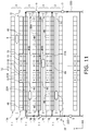
- FIG. 11 is a schematic plan view illustrating an arrangement structure of an automated storeroom system according to a fourth example.
- the automated storeroom system 1 C includes a route 22 along which the transport vehicle 5 travels.
- the route 22 includes a plurality of fourth routes 22 A and a circulation route 22 D.
- Each fourth route 22 A is provided in the first rack 7 A that is disposed adjacent to the second rack 7 B, wherein the first rack 7 A and the second rack 7 B belong to different automated storerooms 3 and disposed adjacent to each other back to back.
- the fourth route 22 A passes through the lower portions of the first rack 7 A in the first horizontal direction.
- the fourth route 22 A is provided from one end of the lower portion of the first rack 7 A to the other end of the first rack 7 A in the first horizontal direction.
- a passing space is provided to allow the transport vehicles 5 to pass therethrough.
- the passing space extends passing through the first rack 7 A in the first horizontal direction.
- structural members such as lattices are not provided.
- the transport vehicle 5 can travel to the second rack 7 B and transfer the article A from or to the second rack 7 B.
- the loading ports 13 and the unloading ports 15 are provided.
- the loading port 13 is, at a level corresponding to the lowest shelf 7 a of the rack 7 , provided in plurality (herein, three) in a row to be adjacent to each other in the first horizontal direction.
- the unloading port 15 is, at a level corresponding to the lowest shelf 7 a of the rack 7 , provided in plurality (herein, three) in a row to be adjacent to each other in the first horizontal direction.
- a group consisting of the unloading ports 15 and a group consisting of the loading ports 13 are adjacent to each other in the first horizontal direction.
- a transfer space is defined between the lower portions of the first rack 7 A and the lower portions of the second rack 7 B through which the transport vehicle 5 can travel.
- the transfer space extends passing through the first rack 7 A and the second rack 7 B in the second horizontal direction.
- structural members such as lattices and back-side braces are not provided.
- the circulation route 22 D is connected with the fourth route 22 A outside the rack 7 .
- the circulation route 22 D is a one-way route along which the transport vehicle 5 travels in one direction.
- the circulation route 22 D is connected with upstream sides of the fourth routes 22 A outside the rack 7 .
- the circulation route 22 D is connected with the downstream sides of the fourth routes 22 A outside the rack 7 .
- the circulation route 22 D continuously extends from the downstream sides of the fourth routes 22 A to the upstream sides of the fourth routes 22 A.
- the automated storeroom system 1 C includes a travelling restriction device 41 B.
- the travelling restriction device 41 B is provided, in plan view, only at the opening portions 7 b of the loading ports 13 and the unloading ports 15 near the crane passage 11 .
- the travelling restriction device 41 B is disposed only at the front parts of the loading ports 13 and the unloading ports 15 , where the stacker crane 9 has to perform the transfer. Accordingly, during the normal operation, the travelling restriction member 43 is positioned at the travelling non-restriction position so that the stacker crane 9 can access the loading ports 13 and the unloading ports 15 . If the stacker crane 9 is abnormally stopped, the travelling restriction member 43 is moved to the travelling restriction position so that worker W cannot travel to the other crane passage 11 .
- the automated storeroom system 1 C includes a first fixed travelling restriction member 48 (one example of the second travelling restriction member).
- the first fixed travelling restriction member 48 is provided at a rear part and side parts of the lowest shelf 7 a of the second rack 7 B where the loading port 13 and the unloading port 15 do not exist.
- the first fixed travelling restriction member 48 straight with a simple structure.
- the automated storeroom system 1 C includes a second fixed travelling restriction member 49 (one example of the second travelling restriction member).
- the second fixed travelling restriction member 49 is disposed in linear generally between the crane passage 11 and the front part of the first rack 7 A.
- providing the first fixed travelling restriction member 48 and the second fixed travelling restriction member 49 makes it possible to decrease the location of the travelling restriction devices 41 B.
- travelling restriction member of the travelling restriction device is a net in the first example, the travelling restriction member may be any one as long as it restricts the travelling of the worker W in any way.
- FIGS. 12 through 14 such a modification will be explained as a fifth example.
- FIGS. 12 and 13 are views illustrating a loading port of the rack seen from the crane passage in the automated storeroom system according to a fifth example.
- FIG. 14 is a schematic plan view illustrating a loading port of the rack of the automated storeroom system according to the fifth example.
- This automated storeroom system includes a travelling restriction device 61 .
- the travelling restriction device 61 includes a plurality of travelling restriction members 63 .
- the travelling restriction member 63 is disposed, as shown in FIG. 14 , in plan view, between the crane passage 11 and a front part of the rack 7 facing the crane passage 11 .
- the travelling restriction member 63 can move between a travelling restriction position for restricting the travelling of the worker W and a travelling non-restriction position for removing the restriction.
- the travelling restriction member 63 is a stick-like member, and has one end rotatably supported by a post 33 . More specifically, the travelling restriction member 63 has a pair of stick-like members 63 a , and a support portion 63 b fixed to the post 33 and rotatably supporting the stick-like members 63 a .
- the travelling restriction members 63 are disposed at a level corresponding to the opening portions 7 b of the loading ports 13 and at a level corresponding to the underneath entering space 31 a , along one post 33 . As shown in FIG. 14 , the travelling restriction member 63 is disposed out of a boundary line P of the crane passage 11 .
- the travelling restriction member 63 takes, as shown in FIG. 12 , a standing posture along the post 33 at the travelling non-restriction position.
- the travelling restriction member 63 takes, as shown in FIG. 13 , a lying posture to form a partition at the lowest opening portion 7 b (the opening portion 7 b of the loading port 13 ) of the rack 7 and the underneath entering space 31 a at the travelling restriction position.
- the pair of travelling restriction members 63 is open sideward, and their ends are close to each other in the first horizontal direction.
- the travelling restriction device 41 includes a driving device (not shown) that drives the travelling restriction member 63 .
- the driving device has a motor that rotates the travelling restriction member 63 . Accordingly, the travelling restriction member 43 can take a standing posture at the travelling non-restriction position and a lying posture at the travelling restriction position.
- a sensor may be provided that detects invasion by hands or legs of the worker W through gaps of the travelling restriction member 63 .
- the dangerous state is notified to the worker W based on the detected information, thereby improving the safety.
- An automated storeroom system (e.g., automated storeroom systems 1 , 1 A, 1 B, and 1 C) includes a plurality of automated storerooms (e.g., a plurality of automated storerooms 3 ), a transport vehicle (e.g., a transport vehicle 5 ), a travelling restriction member (e.g., travelling restriction members 43 and 63 ).
- the automated storerooms extend in a first horizontal direction (e.g., an arrow X), and have a rack (e.g., a rack 7 ) having a plurality of shelves (e.g., shelves 7 a ), and a stacker crane (e.g., a stacker crane 9 ) that can travel along a passage (e.g., a crane passage 11 ) along the rack.
- the automated storerooms are arranged in a second horizontal direction (e.g., an arrow Y) perpendicular to the first horizontal direction such that back parts of the racks are adjacent to each other.
- the transport vehicle can travel along a transport vehicle travelling passage (e.g., a route 21 ) provided in a lower portion of the rack and extending in the first horizontal direction.
- the travelling restriction member is disposed between the crane passage and a front part of the rack facing the crane passage.
- the travelling restriction member can move between a travelling restriction position for restricting the travelling of the worker (e.g., a worker W) and a travelling non-restriction position for removing the restriction.
- the fifth example can be applied to any of the first through fourth examples.
- the travelling restriction device may be a device configured to move a plurality of bars in the vertical direction.
- the bars extend in a horizontal direction.
- the bars can switch a travelling restriction position to and from a travelling non-restriction position.
- the transport vehicle may have a transfer device such as a slide fork to transfer the article when the transport vehicle is on the route.
- the travelling restriction member in the first example may be a sheet-like member other than a net.
- My systems can be widely applied to the automated storeroom system.
Landscapes
- Engineering & Computer Science (AREA)
- Mechanical Engineering (AREA)
- Warehouses Or Storage Devices (AREA)
- Devices That Are Associated With Refrigeration Equipment (AREA)
Applications Claiming Priority (4)
| Application Number | Priority Date | Filing Date | Title |
|---|---|---|---|
| JP2018050650 | 2018-03-19 | ||
| JPJP2018-050650 | 2018-03-19 | ||
| JP2018-050650 | 2018-03-19 | ||
| PCT/JP2019/005010 WO2019181283A1 (ja) | 2018-03-19 | 2019-02-13 | 自動倉庫システム |
Publications (2)
| Publication Number | Publication Date |
|---|---|
| US20200391944A1 US20200391944A1 (en) | 2020-12-17 |
| US11208266B2 true US11208266B2 (en) | 2021-12-28 |
Family
ID=67986935
Family Applications (1)
| Application Number | Title | Priority Date | Filing Date |
|---|---|---|---|
| US16/971,651 Active 2039-02-27 US11208266B2 (en) | 2018-03-19 | 2019-02-13 | Automated storeroom system |
Country Status (6)
| Country | Link |
|---|---|
| US (1) | US11208266B2 (ja) |
| JP (1) | JP6954450B2 (ja) |
| KR (1) | KR102343008B1 (ja) |
| CN (1) | CN111741910B (ja) |
| TW (1) | TWI774939B (ja) |
| WO (1) | WO2019181283A1 (ja) |
Cited By (2)
| Publication number | Priority date | Publication date | Assignee | Title |
|---|---|---|---|---|
| US20210122571A1 (en) * | 2019-10-25 | 2021-04-29 | Jungheinrich Aktiengesellschaft | Stacking storage arrangement |
| US20210122570A1 (en) * | 2019-10-25 | 2021-04-29 | Jungheinrich Aktiengesellschaft | Stacking storage arrangement and method for operating a stacking storage arrangement |
Families Citing this family (7)
| Publication number | Priority date | Publication date | Assignee | Title |
|---|---|---|---|---|
| CN111731728A (zh) * | 2019-04-30 | 2020-10-02 | 北京京东乾石科技有限公司 | 物品运送系统 |
| ES2946082T3 (es) * | 2019-10-25 | 2023-07-12 | Jungheinrich Ag | Disposición de almacenamiento por apilamiento |
| CN111301357A (zh) * | 2020-03-04 | 2020-06-19 | 博众精工科技股份有限公司 | 换电系统、换电方法和换电站 |
| CN111232530A (zh) * | 2020-03-27 | 2020-06-05 | 上海快仓智能科技有限公司 | 货架和仓储装置 |
| DE102020124809A1 (de) * | 2020-09-23 | 2022-03-24 | Still Gesellschaft Mit Beschränkter Haftung | Verfahren zum Betreiben eines Regallagersystems und Regallagersystem |
| CN112623600A (zh) * | 2021-01-19 | 2021-04-09 | 长江智能科技(广东)股份有限公司 | 超声波人工智能胎模存储库 |
| EP4238901A1 (de) * | 2022-03-03 | 2023-09-06 | Jungheinrich Aktiengesellschaft | Verfahren zum betreiben einer blocklageranordnung und blockanordnung |
Citations (22)
| Publication number | Priority date | Publication date | Assignee | Title |
|---|---|---|---|---|
| US5340262A (en) * | 1990-05-17 | 1994-08-23 | Daifuku Co., Ltd. | Automatic warehousing system and operating file therefor |
| US5564528A (en) * | 1994-02-07 | 1996-10-15 | Daifuku Co., Ltd. | Inward/outward delivery device of automated warehouse |
| JPH11116006A (ja) | 1997-10-17 | 1999-04-27 | Murata Mach Ltd | 自動倉庫システム |
| JPH11116004A (ja) | 1997-10-17 | 1999-04-27 | Murata Mach Ltd | 自動倉庫システム |
| JPH11116005A (ja) | 1997-10-17 | 1999-04-27 | Murata Mach Ltd | 自動倉庫システム |
| JPH11165811A (ja) | 1997-12-05 | 1999-06-22 | Oomu Denki:Kk | 立体自動倉庫 |
| JP2002154607A (ja) | 2000-11-22 | 2002-05-28 | Sumitomo Heavy Ind Ltd | 背面ピッキング式パレット自動倉庫の安全装置 |
| JP3317551B2 (ja) | 1993-07-09 | 2002-08-26 | マツダ株式会社 | 自動倉庫 |
| JP2007217116A (ja) | 2006-02-16 | 2007-08-30 | Dainippon Printing Co Ltd | 倉庫システム |
| US7729797B2 (en) * | 2005-09-09 | 2010-06-01 | Daifuku Co., Ltd. | Article transport apparatus for an article storage system, and a method of operating the apparatus |
| US7787985B2 (en) * | 2005-05-27 | 2010-08-31 | Daifuku Co., Ltd. | Article storage facility and method for operating the facility |
| US20110097182A1 (en) * | 2008-04-14 | 2011-04-28 | SSI Shaefer Noell GmbH Lager-und Systemtechnik | Article separation directly on storage and retrieval device |
| US8670861B2 (en) * | 2009-07-14 | 2014-03-11 | Daifu Co., Ltd. | Article storage facility |
| US20140301810A1 (en) * | 2011-10-26 | 2014-10-09 | Ssi Schaefer Noell Gmbh Lager- Und Systemtechnik | Warehouse system having several aisles and automated method for operating same while the aisle is in a maintenance mode |
| US9452886B2 (en) * | 2012-08-06 | 2016-09-27 | Dematic Systems Gmbh | Method for providing transport units from a storage facility |
| WO2016181734A1 (ja) | 2015-05-11 | 2016-11-17 | 村田機械株式会社 | 自動運転機器システム、非常停止端末、及び操作端末の制御方法 |
| US20170152106A1 (en) * | 2014-08-11 | 2017-06-01 | Ssi Schaefer Noell Gmbh Lager- Und Systemtechnik | Storage and order-picking system and method for providing articles in a particular order |
| US20170203920A1 (en) * | 2016-01-14 | 2017-07-20 | Crown Equipment Corporation | Goods-to-man warehousing comprising multilevel racking, mobile storage units, storage unit transporters, and pick-place vehicle |
| US20170203921A1 (en) * | 2014-08-11 | 2017-07-20 | Ssi Schaefer Noell Gmbh Lager- Und Systemtechnik | Storage and order-picking system and method for providing articles in a particular order |
| US10067501B2 (en) * | 2006-06-19 | 2018-09-04 | Amazon Technologies, Inc. | Method and system for transporting inventory items |
| WO2019008999A1 (ja) | 2017-07-07 | 2019-01-10 | 村田機械株式会社 | 自動倉庫システム |
| US10710803B2 (en) * | 2015-04-22 | 2020-07-14 | Tgw Mechanics Gmbh | Method for transferring part-load consignments to a storage rack for storage, and storage system |
Family Cites Families (9)
| Publication number | Priority date | Publication date | Assignee | Title |
|---|---|---|---|---|
| US3873902A (en) * | 1970-06-15 | 1975-03-25 | Clark Equipment Co | Positioning control system for material handling vehicles |
| JP2865403B2 (ja) * | 1990-09-07 | 1999-03-08 | 株式会社金田機械製作所 | 巻取紙用紙庫及び巻取紙の貯蔵方法 |
| JP2906836B2 (ja) | 1992-06-12 | 1999-06-21 | 村田機械株式会社 | スタッカクレーン |
| JPH07172505A (ja) * | 1993-12-21 | 1995-07-11 | Murata Mach Ltd | 自動倉庫の安全装置 |
| JPH1045212A (ja) * | 1996-08-02 | 1998-02-17 | Toyota Autom Loom Works Ltd | 搬送システム及び搬送システムの移載制御装置 |
| JP4458164B2 (ja) * | 2007-12-28 | 2010-04-28 | 村田機械株式会社 | 自動倉庫 |
| JP4706938B2 (ja) * | 2008-11-21 | 2011-06-22 | 村田機械株式会社 | クリーンルーム用の自動倉庫と自動倉庫での物品の保管方法 |
| US9334115B2 (en) * | 2013-02-27 | 2016-05-10 | Vanderlande Industries B.V. | Device and method for the handling of luggage |
| JP6032239B2 (ja) * | 2014-04-30 | 2016-11-24 | 村田機械株式会社 | 天井走行車用ストッパ |
-
2019
- 2019-02-13 CN CN201980014178.2A patent/CN111741910B/zh active Active
- 2019-02-13 WO PCT/JP2019/005010 patent/WO2019181283A1/ja active Application Filing
- 2019-02-13 US US16/971,651 patent/US11208266B2/en active Active
- 2019-02-13 JP JP2020507424A patent/JP6954450B2/ja active Active
- 2019-02-13 KR KR1020207023515A patent/KR102343008B1/ko active IP Right Grant
- 2019-03-11 TW TW108108057A patent/TWI774939B/zh active
Patent Citations (24)
| Publication number | Priority date | Publication date | Assignee | Title |
|---|---|---|---|---|
| US5340262A (en) * | 1990-05-17 | 1994-08-23 | Daifuku Co., Ltd. | Automatic warehousing system and operating file therefor |
| JP3317551B2 (ja) | 1993-07-09 | 2002-08-26 | マツダ株式会社 | 自動倉庫 |
| US5564528A (en) * | 1994-02-07 | 1996-10-15 | Daifuku Co., Ltd. | Inward/outward delivery device of automated warehouse |
| JPH11116006A (ja) | 1997-10-17 | 1999-04-27 | Murata Mach Ltd | 自動倉庫システム |
| JPH11116004A (ja) | 1997-10-17 | 1999-04-27 | Murata Mach Ltd | 自動倉庫システム |
| JPH11116005A (ja) | 1997-10-17 | 1999-04-27 | Murata Mach Ltd | 自動倉庫システム |
| JPH11165811A (ja) | 1997-12-05 | 1999-06-22 | Oomu Denki:Kk | 立体自動倉庫 |
| JP2002154607A (ja) | 2000-11-22 | 2002-05-28 | Sumitomo Heavy Ind Ltd | 背面ピッキング式パレット自動倉庫の安全装置 |
| US7787985B2 (en) * | 2005-05-27 | 2010-08-31 | Daifuku Co., Ltd. | Article storage facility and method for operating the facility |
| US7729797B2 (en) * | 2005-09-09 | 2010-06-01 | Daifuku Co., Ltd. | Article transport apparatus for an article storage system, and a method of operating the apparatus |
| JP2007217116A (ja) | 2006-02-16 | 2007-08-30 | Dainippon Printing Co Ltd | 倉庫システム |
| US10067501B2 (en) * | 2006-06-19 | 2018-09-04 | Amazon Technologies, Inc. | Method and system for transporting inventory items |
| US20110097182A1 (en) * | 2008-04-14 | 2011-04-28 | SSI Shaefer Noell GmbH Lager-und Systemtechnik | Article separation directly on storage and retrieval device |
| US8670861B2 (en) * | 2009-07-14 | 2014-03-11 | Daifu Co., Ltd. | Article storage facility |
| US20140301810A1 (en) * | 2011-10-26 | 2014-10-09 | Ssi Schaefer Noell Gmbh Lager- Und Systemtechnik | Warehouse system having several aisles and automated method for operating same while the aisle is in a maintenance mode |
| US9452886B2 (en) * | 2012-08-06 | 2016-09-27 | Dematic Systems Gmbh | Method for providing transport units from a storage facility |
| US20170152106A1 (en) * | 2014-08-11 | 2017-06-01 | Ssi Schaefer Noell Gmbh Lager- Und Systemtechnik | Storage and order-picking system and method for providing articles in a particular order |
| US20170203921A1 (en) * | 2014-08-11 | 2017-07-20 | Ssi Schaefer Noell Gmbh Lager- Und Systemtechnik | Storage and order-picking system and method for providing articles in a particular order |
| US10710803B2 (en) * | 2015-04-22 | 2020-07-14 | Tgw Mechanics Gmbh | Method for transferring part-load consignments to a storage rack for storage, and storage system |
| WO2016181734A1 (ja) | 2015-05-11 | 2016-11-17 | 村田機械株式会社 | 自動運転機器システム、非常停止端末、及び操作端末の制御方法 |
| US20180141751A1 (en) | 2015-05-11 | 2018-05-24 | Murata Machinery, Ltd. | Automated equipment system, emergency stop terminal, and operation terminal control method |
| US20170203920A1 (en) * | 2016-01-14 | 2017-07-20 | Crown Equipment Corporation | Goods-to-man warehousing comprising multilevel racking, mobile storage units, storage unit transporters, and pick-place vehicle |
| WO2019008999A1 (ja) | 2017-07-07 | 2019-01-10 | 村田機械株式会社 | 自動倉庫システム |
| US20200087070A1 (en) | 2017-07-07 | 2020-03-19 | Murata Machinery, Ltd. | Automated storeroom system |
Cited By (3)
| Publication number | Priority date | Publication date | Assignee | Title |
|---|---|---|---|---|
| US20210122571A1 (en) * | 2019-10-25 | 2021-04-29 | Jungheinrich Aktiengesellschaft | Stacking storage arrangement |
| US20210122570A1 (en) * | 2019-10-25 | 2021-04-29 | Jungheinrich Aktiengesellschaft | Stacking storage arrangement and method for operating a stacking storage arrangement |
| US11834269B2 (en) * | 2019-10-25 | 2023-12-05 | Jungheinrich Aktiengesellschaft | Stacking storage arrangement and method for operating a stacking storage arrangement |
Also Published As
| Publication number | Publication date |
|---|---|
| TW201938465A (zh) | 2019-10-01 |
| CN111741910A (zh) | 2020-10-02 |
| CN111741910B (zh) | 2021-12-07 |
| TWI774939B (zh) | 2022-08-21 |
| KR102343008B1 (ko) | 2021-12-24 |
| JPWO2019181283A1 (ja) | 2021-02-12 |
| KR20200105937A (ko) | 2020-09-09 |
| JP6954450B2 (ja) | 2021-10-27 |
| US20200391944A1 (en) | 2020-12-17 |
| WO2019181283A1 (ja) | 2019-09-26 |
Similar Documents
| Publication | Publication Date | Title |
|---|---|---|
| US11208266B2 (en) | Automated storeroom system | |
| US11084656B2 (en) | Automated storeroom system | |
| CN105966822B (zh) | 升降输送装置 | |
| US7575407B2 (en) | Article storage facility | |
| KR102276842B1 (ko) | 층간 반송 설비 | |
| JP6304045B2 (ja) | 物品保管設備 | |
| US20220363477A1 (en) | Automated storage and retrieval system comprising a barrier | |
| JPH0571483B2 (ja) | ||
| US10081491B2 (en) | Article storage facility | |
| JP5549868B2 (ja) | 物品収納設備 | |
| JP6954076B2 (ja) | 搬送装置 | |
| JP3568014B2 (ja) | 物品保管設備 | |
| JP2000264406A (ja) | 横渡し機能付き自動倉庫 | |
| JP3531720B2 (ja) | 物品保管設備 | |
| JP6448945B2 (ja) | パズル式格納庫の制御装置、及びその制御方法並びに制御プログラム | |
| US20230415991A1 (en) | Article Storage Facility | |
| JP4396887B2 (ja) | 自動倉庫 | |
| KR0129582Y1 (ko) | 물품저장설비 | |
| JP2555112Y2 (ja) | スタッカクレーンの荷異常検出装置 | |
| JP2003278396A (ja) | 立体駐車場 | |
| JPS6175174A (ja) | 立体駐車場 |
Legal Events
| Date | Code | Title | Description |
|---|---|---|---|
| AS | Assignment |
Owner name: MURATA MACHINERY, LTD., JAPAN Free format text: ASSIGNMENT OF ASSIGNORS INTEREST;ASSIGNOR:KAKINUKI, TSUYOSHI;REEL/FRAME:053556/0834 Effective date: 20200722 |
|
| FEPP | Fee payment procedure |
Free format text: ENTITY STATUS SET TO UNDISCOUNTED (ORIGINAL EVENT CODE: BIG.); ENTITY STATUS OF PATENT OWNER: LARGE ENTITY |
|
| STPP | Information on status: patent application and granting procedure in general |
Free format text: DOCKETED NEW CASE - READY FOR EXAMINATION |
|
| STPP | Information on status: patent application and granting procedure in general |
Free format text: NOTICE OF ALLOWANCE MAILED -- APPLICATION RECEIVED IN OFFICE OF PUBLICATIONS |
|
| STPP | Information on status: patent application and granting procedure in general |
Free format text: PUBLICATIONS -- ISSUE FEE PAYMENT VERIFIED |
|
| STCF | Information on status: patent grant |
Free format text: PATENTED CASE |