KR20180098421A - Substrate processing systems, apparatus, and methods with factory interface environmental controls - Google Patents
Substrate processing systems, apparatus, and methods with factory interface environmental controls Download PDFInfo
- Publication number
- KR20180098421A KR20180098421A KR1020187024379A KR20187024379A KR20180098421A KR 20180098421 A KR20180098421 A KR 20180098421A KR 1020187024379 A KR1020187024379 A KR 1020187024379A KR 20187024379 A KR20187024379 A KR 20187024379A KR 20180098421 A KR20180098421 A KR 20180098421A
- Authority
- KR
- South Korea
- Prior art keywords
- factory interface
- electronic device
- processing system
- chamber
- device processing
- Prior art date
- Legal status (The legal status is an assumption and is not a legal conclusion. Google has not performed a legal analysis and makes no representation as to the accuracy of the status listed.)
- Granted
Links
Images


Classifications
-
- H01L21/67253—
-
- H—ELECTRICITY
- H10—SEMICONDUCTOR DEVICES; ELECTRIC SOLID-STATE DEVICES NOT OTHERWISE PROVIDED FOR
- H10P—GENERIC PROCESSES OR APPARATUS FOR THE MANUFACTURE OR TREATMENT OF DEVICES COVERED BY CLASS H10
- H10P72/00—Handling or holding of wafers, substrates or devices during manufacture or treatment thereof
- H10P72/04—Apparatus for manufacture or treatment
- H10P72/0451—Apparatus for manufacturing or treating in a plurality of work-stations
- H10P72/0468—Apparatus for manufacturing or treating in a plurality of work-stations comprising a chamber adapted to a particular process
-
- H01L21/67028—
-
- H01L21/67207—
-
- H01L21/67248—
-
- H01L21/67772—
-
- H01L22/30—
-
- H—ELECTRICITY
- H10—SEMICONDUCTOR DEVICES; ELECTRIC SOLID-STATE DEVICES NOT OTHERWISE PROVIDED FOR
- H10P—GENERIC PROCESSES OR APPARATUS FOR THE MANUFACTURE OR TREATMENT OF DEVICES COVERED BY CLASS H10
- H10P72/00—Handling or holding of wafers, substrates or devices during manufacture or treatment thereof
- H10P72/04—Apparatus for manufacture or treatment
- H10P72/0402—Apparatus for fluid treatment
- H10P72/0406—Apparatus for fluid treatment for cleaning followed by drying, rinsing, stripping, blasting or the like
-
- H—ELECTRICITY
- H10—SEMICONDUCTOR DEVICES; ELECTRIC SOLID-STATE DEVICES NOT OTHERWISE PROVIDED FOR
- H10P—GENERIC PROCESSES OR APPARATUS FOR THE MANUFACTURE OR TREATMENT OF DEVICES COVERED BY CLASS H10
- H10P72/00—Handling or holding of wafers, substrates or devices during manufacture or treatment thereof
- H10P72/06—Apparatus for monitoring, sorting, marking, testing or measuring
- H10P72/0602—Temperature monitoring
-
- H—ELECTRICITY
- H10—SEMICONDUCTOR DEVICES; ELECTRIC SOLID-STATE DEVICES NOT OTHERWISE PROVIDED FOR
- H10P—GENERIC PROCESSES OR APPARATUS FOR THE MANUFACTURE OR TREATMENT OF DEVICES COVERED BY CLASS H10
- H10P72/00—Handling or holding of wafers, substrates or devices during manufacture or treatment thereof
- H10P72/06—Apparatus for monitoring, sorting, marking, testing or measuring
- H10P72/0604—Process monitoring, e.g. flow or thickness monitoring
-
- H—ELECTRICITY
- H10—SEMICONDUCTOR DEVICES; ELECTRIC SOLID-STATE DEVICES NOT OTHERWISE PROVIDED FOR
- H10P—GENERIC PROCESSES OR APPARATUS FOR THE MANUFACTURE OR TREATMENT OF DEVICES COVERED BY CLASS H10
- H10P74/00—Testing or measuring during manufacture or treatment of wafers, substrates or devices
- H10P74/27—Structural arrangements therefor
-
- H—ELECTRICITY
- H10—SEMICONDUCTOR DEVICES; ELECTRIC SOLID-STATE DEVICES NOT OTHERWISE PROVIDED FOR
- H10P—GENERIC PROCESSES OR APPARATUS FOR THE MANUFACTURE OR TREATMENT OF DEVICES COVERED BY CLASS H10
- H10P72/00—Handling or holding of wafers, substrates or devices during manufacture or treatment thereof
- H10P72/30—Handling or holding of wafers, substrates or devices during manufacture or treatment thereof for conveying, e.g. between different workstations
- H10P72/34—Handling or holding of wafers, substrates or devices during manufacture or treatment thereof for conveying, e.g. between different workstations the wafers being stored in a carrier, involving loading and unloading
- H10P72/3406—Handling or holding of wafers, substrates or devices during manufacture or treatment thereof for conveying, e.g. between different workstations the wafers being stored in a carrier, involving loading and unloading involving removal of lid, door or cover
Landscapes
- Container, Conveyance, Adherence, Positioning, Of Wafer (AREA)
- Engineering & Computer Science (AREA)
- Manufacturing & Machinery (AREA)
- Exposure Of Semiconductors, Excluding Electron Or Ion Beam Exposure (AREA)
- Cleaning Or Drying Semiconductors (AREA)
- Drying Of Semiconductors (AREA)
- Physics & Mathematics (AREA)
- General Physics & Mathematics (AREA)
- Automation & Control Theory (AREA)
Abstract
팩토리 인터페이스의 환경 제어를 포함하는 전자 디바이스 프로세싱 시스템들이 설명된다. 하나의 전자 디바이스 프로세싱 시스템은, 팩토리 인터페이스 챔버를 갖는 팩토리 인터페이스, 팩토리 인터페이스에 커플링된 로드 락 장치, 팩토리 인터페이스에 커플링된 하나 또는 그 초과의 기판 캐리어들, 및 팩토리 인터페이스에 커플링된 환경 제어 시스템을 가지며, 환경 제어 시스템은, 팩토리 인터페이스 챔버 내의, 상대 습도, 온도, 산소의 양, 또는 비활성 가스의 양 중 하나를 모니터링하거나 또는 제어하도록 동작한다. 다른 양상에서, 팩토리 인터페이스 챔버 내의 캐리어 퍼지 챔버의 퍼징이 제공된다. 기판들을 프로세싱하기 위한 방법들이 설명되고, 다수의 다른 양상들이 설명된다.Electronic device processing systems including environmental control of a factory interface are described. One electronic device processing system includes a factory interface having a factory interface chamber, a load lock device coupled to the factory interface, one or more substrate carriers coupled to the factory interface, and an environmental control coupled to the factory interface System and the environmental control system operates to monitor or control one of the relative humidity, temperature, amount of oxygen, or amount of inert gas in the factory interface chamber. In another aspect, purging of the carrier purge chamber within the factory interface chamber is provided. Methods for processing substrates are described, and a number of other aspects are described.
Description
관련 출원Related application
[0001] 본원은, 발명의 명칭이 "팩토리 인터페이스 환경 제어들을 갖는 기판 프로세싱 시스템들, 장치, 및 방법들(SUBSTRATE PROCESSING SYSTEMS, APPARATUS, AND METHODS WITH FACTORY INTERFACE ENVIRONMENTAL CONTROLS)"이고, 2013년 8월 12일자로 출원된 미국 가특허 출원 번호 제 61/865,046 호(대리인 도켓 번호 제 21149/USA/L 호)를 우선권으로 주장하며, 그 미국 가특허 출원은, 이로써, 모든 목적들에 대해 그 전체가 인용에 의해 본원에 포함된다.[0001] This application is a continuation-in-part of application Ser. No. 12 / 12,133, titled "SUBSTRATE PROCESSING SYSTEMS, APPARATUS AND METHODS WITH FACTORY INTERFACE ENVIRONMENTAL CONTROLS" US patent application Ser. No. 61 / 865,046 (Attorney Docket No. 21149 / USA / L), filed on the same date, claims that the US patent application is hereby incorporated by reference in its entirety for all purposes Which is incorporated herein by reference.
[0002] 실시예들은 전자 디바이스 제조에 관련되고, 더 구체적으로는, EFEM(equipment front end module)들, 및 기판들을 프로세싱하기 위한 장치, 시스템들 및 방법들에 관련된다.[0002] Embodiments relate to the manufacture of electronic devices, and more particularly to equipment front ends modules (EFEMs), and devices, systems and methods for processing substrates.
[0003] 전자 디바이스 제조 시스템들은, 이송 챔버를 갖는 메인프레임 하우징(housing) 주위에 배열된 다수의 프로세스 챔버들, 및 이송 챔버 내로 기판들을 전달하도록 구성된 하나 또는 그 초과의 로드 락 챔버들을 포함할 수 있다. 이러한 시스템들은, 예컨대, 이송 챔버에 하우징될 수 있는 이송 로봇을 채용할 수 있다. 이송 로봇은 SCARA(selectively compliant articulated robot arm) 로봇 등일 수 있고, 하나 또는 그 초과의 로드 락 챔버들과 다양한 챔버들 사이에서 기판들을 운송하도록 적응될 수 있다. 예컨대, 이송 로봇은, 기판들을, 프로세스 챔버로부터 프로세스 챔버로, 로드 락 챔버로부터 프로세스 챔버로, 그리그 그 반대로 운송할 수 있다.[0003] Electronic device manufacturing systems may include a plurality of process chambers arranged around a mainframe housing having a transfer chamber, and one or more load lock chambers configured to transfer substrates into the transfer chamber have. Such systems may employ, for example, a transfer robot that can be housed in a transfer chamber. The transfer robot can be a SCARA (optionally compliant articulated robot arm) robot or the like, and can be adapted to transport substrates between one or more load lock chambers and various chambers. For example, the transport robot can transport substrates from a process chamber to a process chamber, from a load lock chamber to a process chamber, and vice versa.
[0004] 반도체 컴포넌트 제조에서의 기판들의 프로세싱은 일반적으로, 다수의 툴들에서 수행되며, 여기에서, 기판들은, 기판 캐리어들(예컨대, 전방 개방 통합 포드(Front Opening Unified Pod)들 또는 FOUP들)로, 툴들 사이를 이동한다. FOUP들은 EFEM(종종, "팩토리 인터페이스 또는 FI"라고 지칭됨)에 도킹될(docked) 수 있고, EFEM은 내부에 로드/언로드 로봇을 포함하고, 로드/언로드 로봇은, 툴의 하나 또는 그 초과의 로드 락들과 FOUP들 사이에서 기판들을 이송하고, 그에 따라, 프로세싱을 위한 기판들의 통과를 허용하도록 동작가능하다. 기존의 시스템들은 효율 및/또는 프로세스 품질 개선들로부터 이익을 얻을 수 있다.[0004] The processing of substrates in the manufacture of semiconductor components is generally performed in a number of tools, wherein the substrates are transferred to substrate carriers (e.g., Front Opening Unified Pods or FOUPs) , And moves between tools. FOUPs may be docked to EFEM (often referred to as a "factory interface or FI"), EFEMs include load / unload robots therein, and load / unload robots may include one or more of the tools Is operable to transfer substrates between the load locks and the FOUPs and thus allow the passage of substrates for processing. Existing systems may benefit from efficiency and / or process quality improvements.
[0005] 따라서, 기판들의 프로세싱에서 개선된 효율 및/또는 능력을 갖는 시스템들, 장치, 및 방법들이 요구된다.[0005] Accordingly, there is a need for systems, apparatus, and methods that have improved efficiency and / or capability in processing substrates.
[0006] 일 양상에서, 전자 디바이스 프로세싱 시스템이 제공된다. 전자 디바이스 프로세싱 시스템은, 팩토리 인터페이스 챔버를 포함하는 팩토리 인터페이스, 팩토리 인터페이스에 커플링된 로드 락 장치, 팩토리 인터페이스에 커플링된 하나 또는 그 초과의 기판 캐리어들, 및 팩토리 인터페이스에 커플링된 환경 제어 시스템을 포함하며, 환경 제어 시스템은, 팩토리 인터페이스 챔버 내의, 상대 습도, 온도, O2의 양, 또는 비활성 가스의 양 중 하나를 모니터링하거나 또는 제어하도록 동작한다.[0006] In an aspect, an electronic device processing system is provided. The electronic device processing system includes a factory interface including a factory interface chamber, a load lock device coupled to the factory interface, one or more substrate carriers coupled to the factory interface, and an environmental control system coupled to the factory interface Wherein the environmental control system is operative to monitor or control one of the relative humidity, temperature, amount of O 2 , or amount of inert gas in the factory interface chamber.
[0007] 다른 양상에서, 전자 디바이스 프로세싱 시스템 내에서 기판들을 프로세싱하는 방법이 제공된다. 방법은, 팩토리 인터페이스 챔버를 포함하는 팩토리 인터페이스, 팩토리 인터페이스에 도킹된 하나 또는 그 초과의 기판 캐리어들, 팩토리 인터페이스에 커플링된, 하나 또는 그 초과의 로드 락 챔버들을 포함하는 로드 락 장치, 및 가능하게는, 접근 도어(access door)를 제공하는 단계, 및 환경 전제 조건(environmental precondition)들을 만족시키기 위해, 팩토리 인터페이스 챔버에서의 환경 조건들을 제어하는 단계를 포함한다.[0007] In another aspect, a method of processing substrates within an electronic device processing system is provided. The method may include a factory interface including a factory interface chamber, one or more substrate carriers docked to the factory interface, a load lock device coupled to the factory interface, the load lock device including one or more load lock chambers, , Providing an access door, and controlling environmental conditions in the factory interface chamber to satisfy environmental preconditions.
[0008] 또 다른 방법 양상에서, 전자 디바이스 프로세싱 시스템 내에서 기판들을 프로세싱하는 방법이 제공된다. 방법은, 팩토리 인터페이스 챔버를 포함하는 팩토리 인터페이스, 팩토리 인터페이스에 도킹된 하나 또는 그 초과의 기판 캐리어들, 팩토리 인터페이스 챔버 내의 하나 또는 그 초과의 캐리어 퍼지 챔버들, 및 팩토리 인터페이스에 커플링된 하나 또는 그 초과의 로드 락 챔버들을 제공하는 단계, 및 팩토리 인터페이스 챔버 및 하나 또는 그 초과의 캐리어 퍼지 챔버들에서의 환경 조건들을 제어하는 단계를 포함한다.[0008] In another aspect, a method of processing substrates within an electronic device processing system is provided. The method may include a factory interface including a factory interface chamber, one or more substrate carriers docked to a factory interface, one or more carrier purge chambers in a factory interface chamber, and one or more And controlling environmental conditions in the factory interface chamber and one or more of the carrier purge chambers.
[0009] 다수의 다른 양상들이, 본 발명의 이러한 그리고 다른 실시예들에 따라 제공된다. 본 발명의 실시예들의 다른 특징들 및 양상들은, 다음의 상세한 설명, 첨부된 청구항들, 및 첨부 도면들로부터 더 완전히 명백하게 될 것이다.[0009] A number of other aspects are provided in accordance with these and other embodiments of the present invention. Other features and aspects of embodiments of the present invention will become more fully apparent from the following detailed description, the appended claims, and the accompanying drawings.
[00010] 아래에서 설명되는 도면들은 예시적인 목적들만을 위한 것이고, 반드시 실척대로 도시된 것은 아니다. 도면들은, 어떠한 방식으로도, 본 발명의 범위를 제한하는 것으로 의도되지 않는다.
[00011] 도 1은, 실시예들에 따른, 팩토리 인터페이스 환경 제어들을 포함하는 전자 디바이스 프로세싱 시스템의 개략적인 상면도를 예시한다.
[00012] 도 2는, 실시예들에 따른, 전자 디바이스 프로세싱 시스템 내에서 기판들을 프로세싱하는 방법을 도시하는 흐름도를 예시한다.
[00013] 도 3은, 실시예들에 따른, 비활성 가스 재순환(recirculation) 시스템을 포함하는 전자 디바이스 프로세싱 시스템의 개략적인 상면도를 예시한다.
[00014] 도 4는, 실시예들에 따른, 환경 제어들 및 비활성 가스 재순환을 포함하는 다른 전자 디바이스 프로세싱 시스템의 개략적인 상면도를 예시한다.
[00015] 도 5a는, 실시예들에 따른 캐리어 퍼지 어셈블리의 측단면도를 예시한다.
[00016] 도 5b는, 실시예들에 따른 캐리어 퍼지 어셈블리의 정면도를 예시한다.
[00017] 도 6은, 실시예들에 따른, 전자 디바이스 프로세싱 시스템 내에서 기판들을 프로세싱하는 방법을 도시하는 다른 흐름도를 예시한다.[00010] The drawings described below are for illustrative purposes only and are not necessarily drawn to scale. The drawings are not intended to limit the scope of the invention in any way.
[00011] Figure 1 illustrates a schematic top view of an electronic device processing system including factory interface environment controls, in accordance with embodiments.
[00012] Figure 2 illustrates a flow diagram illustrating a method of processing substrates within an electronic device processing system, in accordance with embodiments.
[00013] Figure 3 illustrates a schematic top view of an electronic device processing system including an inert gas recirculation system, in accordance with embodiments.
[00014] FIG. 4 illustrates a schematic top view of another electronic device processing system, including environmental controls and inert gas recirculation, in accordance with embodiments.
[00015] FIG. 5A illustrates a side cross-sectional view of a carrier purge assembly according to embodiments.
[00016] Figure 5b illustrates a front view of a carrier purge assembly according to embodiments.
[00017] FIG. 6 illustrates another flow diagram illustrating a method of processing substrates within an electronic device processing system, in accordance with embodiments.
[00018] 이제, 첨부 도면들에서 예시되는, 본 개시의 예시적인 실시예들이 상세히 참조될 것이다. 가능한 경우에, 수개의 도면들 전반에 걸쳐 동일한 또는 유사한 부분들을 지칭하기 위해, 도면들 전반에 걸쳐, 동일한 참조 번호들이 사용될 것이다. 본원에서 설명되는 다양한 실시예들의 특징들은, 구체적으로 다르게 기재되지 않는 한, 서로 조합될 수 있다.[00018] Reference will now be made in detail to the exemplary embodiments of the present disclosure, illustrated in the accompanying drawings. Wherever possible, the same reference numbers will be used throughout the drawings to refer to the same or like parts throughout the several views. The features of the various embodiments described herein may be combined with one another, unless specifically stated otherwise.
[00019] 전자 디바이스 제조는, 매우 정밀한 프로세싱, 뿐만 아니라, 다양한 위치들 사이의 기판들의 신속한 운송을 요구할 수 있다. 특히, 기존의 시스템들은, 기판들을, FOUP들과 로드 락들 사이에서 이송할 수 있고, 그 후에, 프로세싱 챔버들 내로 이송할 수 있다. 그러나, 기존의 시스템들은, 비교적 더 높은 습도, 온도, 또는 다른 환경 인자들, 예컨대 너무 높은 산소(O2) 레벨이 관찰되는 경우에 문제들을 겪을 수 있다. 특히, 비교적 높은 습도 레벨들 또는 비교적 높은 O2 레벨들에 대한 노출은 기판 특성들에 대해 악영향을 미칠 수 있다.[00019] Electronic device fabrication can require very precise processing, as well as rapid transport of substrates between various locations. In particular, existing systems can transport substrates between FOUPs and loadlocks, and then transfer them into processing chambers. Existing systems, however, can experience problems when relatively higher humidity, temperature, or other environmental factors are observed, such as too high an oxygen (O 2 ) level. In particular, exposure to relatively high humidity levels or relatively high O 2 levels can adversely affect substrate properties.
[00020] 본 발명의 하나 또는 그 초과의 실시예들에 따르면, 개선된 기판 프로세싱을 제공하도록 적응된 전자 디바이스 프로세싱 시스템들이 제공된다. 본원에서 설명되는 시스템들 및 방법들은, 팩토리 인터페이스의 팩토리 인터페이스 챔버 내의 환경 조건들을 제어함으로써, 기판들의 프로세싱에서의 효율 및/또는 프로세싱 개선들을 제공할 수 있다. 팩토리 인터페이스는, 팩토리 인터페이스에 도킹된(예컨대, 팩토리 인터페이스의 전방(front) 표면에 도킹된) 하나 또는 그 초과의 기판 캐리어들로부터 기판들을 수용하고, 로드/언로드 로봇은, 팩토리 인터페이스의 다른 표면(예컨대, 팩토리 인터페이스의 후방 표면) 상에 커플링된 하나 또는 그 초과의 로드 락들에 기판들을 전달한다. 몇몇 실시예들에서, 하나 또는 그 초과의 환경 파라미터들(예컨대, 상대 습도, 온도, O2의 양, 또는 비활성 가스의 양)이 모니터링되고, 팩토리 인터페이스의 팩토리 인터페이스 챔버에서의 환경에 관한 특정한 전제-조건들이 만족되지 않는 한, 팩토리 인터페이스에 도킹된 임의의 FOUP, 또는 하나 또는 그 초과의 로드 락들이 개방되지 않을 수 있다.[00020] According to one or more embodiments of the present invention, electronic device processing systems adapted to provide improved substrate processing are provided. The systems and methods described herein can provide efficiency and / or processing improvements in the processing of substrates by controlling environmental conditions in the factory interface chamber of the factory interface. The factory interface accepts substrates from one or more substrate carriers docked to the factory interface (e.g., docked to the front surface of the factory interface), and the load / For example, the rear surface of the factory interface). In some embodiments, one or more environmental parameters (e.g., relative humidity, temperature, amount of O 2 , or amount of inert gas) are monitored and the specific premise regarding the environment in the factory interface chamber of the factory interface - Any FOUP docked to the factory interface, or one or more load locks, may not be opened unless the conditions are satisfied.
[00021] 본 발명의 예시적인 방법 및 장치 실시예들의 추가적인 세부사항들이, 여기에서, 도 1 내지 도 6에 관하여 설명된다.Additional details of exemplary methods and apparatus embodiments of the present invention are now described with respect to FIGS. 1-6.
[00022] 도 1은, 본 발명의 하나 또는 그 초과의 실시예들에 따른 전자 디바이스 프로세싱 시스템(100)의 예시적인 실시예의 개략도이다. 전자 디바이스 프로세싱 시스템(100)은, 이송 챔버(102)를 정의하는 하우징 벽들을 갖는 메인프레임 하우징(101)을 포함할 수 있다. 이송 로봇(103)(점선 원으로 도시됨)은, 적어도 부분적으로, 이송 챔버(102) 내에 하우징될 수 있다. 이송 로봇(103)은, 이송 로봇(103)의 암들의 동작을 통해, 기판들을 목적지들에 배치하거나 또는 목적지들로부터 꺼내도록 구성 및 적응될 수 있다. 본원에서 사용되는 바와 같은 기판들은, 실리카-함유 웨이퍼들, 패터닝된 웨이퍼들 등과 같은, 전자 디바이스들 또는 회로 컴포넌트들을 제조하기 위해 사용되는 물건(article)들을 의미할 것이다.[0002] FIG. 1 is a schematic diagram of an exemplary embodiment of an electronic
[00023] 도시된 실시예에서, 이송 로봇(103)은, 예컨대, 미국 특허 공개 번호 제 2010/0178147 호에서 개시된 로봇과 같은, 이송 챔버(102)에 커플링되고 이송 챔버(102)로부터 접근 가능한 다양한 트윈 챔버들을 서비싱(service)하도록 적응된 임의의 적합한 타입의 오프-액시스 로봇(off-axis robot)일 수 있다. 다른 오프-액시스 로봇들이 사용될 수 있다. 오프-액시스 로봇은, 일반적으로 이송 챔버(102)의 중심에 센터링된(centered), 방사상으로, 로봇의 숄더(shoulder) 회전 축을 향하여 또는 로봇의 숄더 회전 축으로부터 떨어지게 연장시키는 것 이외에, 엔드 이펙터(end effector)를 연장시키도록 동작할 수 있는 임의의 로봇 구성이다.[00023] In the illustrated embodiment, the
[00024] 이송 로봇(103)의 다양한 암 컴포넌트들의 모션은, 제어기(125)로부터 지시되는 바와 같은, 이송 로봇(103)의 복수의 구동 모터들을 포함하는 구동 어셈블리(미도시)로의 적합한 커맨드(command)들에 의해 제어될 수 있다. 제어기(125)로부터의 신호들은 이송 로봇(103)의 다양한 컴포넌트들의 모션을 야기할 수 있다. 포지션 인코더(position encoder)들 등과 같은 다양한 센서들에 의해, 컴포넌트들 중 하나 또는 그 초과에 대해, 적합한 피드백 메커니즘들이 제공될 수 있다.The motion of the various arm components of the
[00025] 이송 로봇(103)은, 이송 챔버(102)에서 대략 중심에 위치될 수 있는 숄더 축을 중심으로 회전가능한 암들을 포함할 수 있다. 이송 로봇(103)은, 이송 챔버(102)의 하부 부분을 형성하는 하우징 벽(예컨대, 플로어)에 부착되도록 적응된 베이스를 포함할 수 있다. 그러나, 몇몇 실시예들에서, 이송 로봇(103)은 천장에 부착될 수 있다. 로봇(103)은, 트윈 챔버들(예컨대, 나란히 있는(side-by-side) 챔버들)을 서비싱하도록 적응된, 듀얼 SCARA 로봇 또는 다른 타입의 듀얼 로봇일 수 있다. 다른 타입들의 프로세싱 챔버 배향(orientation)들, 뿐만 아니라, 이송 로봇들이 사용될 수 있다.The
[00026] 이송 로봇(103)의 암 컴포넌트들의 회전은, 종래의 가변 릴럭턴스(reluctance) 또는 영구 자석 전기 모터와 같은 임의의 적합한 구동 모터에 의해 제공될 수 있다. 암들은 베이스에 관하여 X-Y 평면에서 회전되도록 적응될 수 있다. 기판들을 운반하도록 적응된 임의의 적합한 수의 암 컴포넌트들 및 엔드 이펙터들이 사용될 수 있다.The rotation of the arm components of the
[00027] 부가적으로, 몇몇 실시예들에서, 이송 로봇(103)의 구동 어셈블리는 Z-축 모션 능력을 포함할 수 있다. 특히, 모터 하우징은, 모션 리스트릭터(motion restrictor)에 의해, 외측 케이싱에 관한 회전이 제약될 수 있다. 모션 리스트릭터는, 외측 케이싱에 관한 모터 하우징의 회전을 억제하지만, 수직 방향을 따르는, 모터 하우징 및 연결된 암들의 Z-축(수직) 모션을 허용하도록 기능하는, 2개 또는 그 초과의 선형 베어링들, 또는 다른 타입의 베어링 또는 슬라이드 메커니즘들일 수 있다. 수직 모션은 수직 모터에 의해 제공될 수 있다. 수직 모터의 회전은, 모터 하우징에 커플링되거나 또는 모터 하우징과 일체화된 리시버(receiver)에서 리드 스크류를 회전시키도록 동작할 수 있다. 이러한 회전은, 모터 하우징, 그리고 따라서, 암들, 하나 또는 그 초과의 부착된 엔드 이펙터들, 및 그 위에 지지되는 기판들을 수직으로 평행 이동(translate)시킬 수 있다. 몇몇 실시예들에서, 적합한 밀봉이 모터 하우징과 베이스 사이를 밀봉할 수 있고, 그에 의해, 수직 모션이 수용될 수 있고, 이송 챔버(102) 내에 진공이 보유될 수 있다.[00027] Additionally, in some embodiments, the drive assembly of the
[00028] 도시된 실시예에서의 이송 챔버(102)는, 형상이 대체로 정사각형 또는 약간 직사각형일 수 있고, 제 1 면(facet)(102A), 제 1 면(102A)과 대향하는 제 2 면(102B), 제 3 면(102C), 및 제 3 면(102C)과 대향하는 제 4 면(102D)을 포함할 수 있다. 이송 로봇(103)은 바람직하게, 챔버 세트들 내로 동시에 듀얼 기판들을 이송하고 그리고/또는 리트랙팅(retracting)하는 것에 능숙할 수 있다. 제 1 면(102A), 제 2 면(102B), 제 3 면(102C), 및 제 4 면(102D)은 대체로 평탄할 수 있고, 챔버 세트들 내로의 진입로(entryway)들은 각각의 면들을 따라 놓여 있을 수 있다. 그러나, 다른 적합한 형상의 메인프레임 하우징(101), 및 다른 적합한 수의 면들 및 프로세싱 챔버들이 가능하다.[00028] The
[00029] 이송 로봇(103)에 대한 목적지들은 제 1 프로세싱 챔버 세트(108A, 108B)일 수 있고, 제 1 프로세싱 챔버 세트(108A, 108B)는 제 1 면(102A)에 커플링되고, 제 1 프로세싱 챔버 세트(108A, 108B)에 전달되는 기판들에 대해 프로세스를 수행하도록 구성될 수 있고 동작가능할 수 있다. 프로세스는, 임의의 적합한 프로세스, 예컨대, 플라즈마 기상 증착(PVD) 또는 화학 기상 증착(CVD), 에칭, 어닐링, 사전-세정, 금속 또는 금속 산화물 제거 등일 수 있다. 다른 프로세스들이, 제 1 프로세싱 챔버 세트(108A, 108B)에서 기판들에 대해 수행될 수 있다.The destinations for the
[00030] 이송 로봇(103)에 대한 목적지들은 또한, 일반적으로, 제 1 프로세스 챔버 세트(108A, 108B) 반대편에 있을 수 있는 제 2 프로세스 챔버 세트(108C, 108D)일 수 있다. 제 2 프로세스 챔버 세트(108C, 108D)는 제 2 면(102B)에 커플링될 수 있고, 기판들에 대해, 위에서 언급된 프로세스들 중 임의의 프로세스와 같은 임의의 적합한 프로세스를 수행하도록 구성될 수 있고 적응될 수 있다. 마찬가지로, 이송 로봇(103)에 대한 목적지들은 또한, 일반적으로, 제 3 면(102C)에 커플링된 로드 락 장치(112) 반대편에 있을 수 있는 제 3 프로세스 챔버 세트(108E, 108F)일 수 있다. 제 3 프로세스 챔버 세트(108E, 108F)는, 기판들에 대해, 위에서 언급된 프로세스들 중 임의의 프로세스와 같은 임의의 적합한 프로세스를 수행하도록 구성될 수 있고 적응될 수 있다.The destinations for the
[00031] 기판들은 팩토리 인터페이스(114)로부터 이송 챔버(102) 내로 수용될 수 있고, 또한, 팩토리 인터페이스(114)의 표면(예컨대, 후방 벽)에 커플링된 로드 락 장치(112)를 통해, 이송 챔버(102)에서 팩토리 인터페이스(114)로 빠져나갈 수 있다. 로드 락 장치(112)는 하나 또는 그 초과의 로드 락 챔버들(예컨대, 로드 락 챔버들(112A, 112B))을 포함할 수 있다. 로드 락 장치(112)에 포함된 로드 락 챔버들(112A, 112B)은 SWLL(single wafer load locks) 챔버들 또는 다중-웨이퍼(multi-wafer) 챔버들일 수 있다. 몇몇 실시예들에서, 로드 락 장치(112)는, 인입되는(incoming) 기판들이 팩토리 인터페이스(114)로부터 이송 챔버(102) 내로 통과되기 전에, 인입되는 기판들에 대해 탈기(degassing) 프로세스가 수행될 수 있도록, 기판을 섭씨 약 200 도 초과로 가열하기 위한 가열 플랫폼/장치를 포함할 수 있다.Substrates may be received from the
[00032] 팩토리 인터페이스(114)는, 팩토리 인터페이스 챔버(114C)를 형성하는 (전방, 후방, 2개의 측면 벽들, 상단, 및 바닥을 포함하는) 측벽 표면들을 갖는 임의의 인클로저(enclosure)일 수 있다. 하나 또는 그 초과의 로드 포트들(115)이 팩토리 인터페이스(114)의 표면들(예컨대, 전방 표면들) 상에 제공될 수 있고, 하나 또는 그 초과의 로드 포트들(115)에서 하나 또는 그 초과의 기판 캐리어들(116)(예컨대, 전방 개방 통합 포드들 또는 FOUP들)을 수용하도록 구성될 수 있고 적응될 수 있다.The
[00033] 팩토리 인터페이스(114)는, 팩토리 인터페이스(114)의 팩토리 인터페이스 챔버(114C) 내에 종래의 구조(construction)의 적합한 로드/언로드 로봇(117)(점선으로 도시됨)을 포함할 수 있다. 로드/언로드 로봇(117)은, 기판 캐리어들(116)의 도어들이 개방되면, 하나 또는 그 초과의 기판 캐리어들(116)로부터 기판들을 꺼내고, 팩토리 인터페이스 챔버(114C)를 통해, 그리고 로드 락 장치(112)에 제공될 수 있는 바와 같은 하나 또는 그 초과의 로드 락 챔버들(112A, 112B) 내로 기판들을 공급하도록 구성될 수 있고 동작할 수 있다. 이송 챔버(102)와 팩토리 인터페이스 챔버(114C) 사이의 기판들의 이송을 허용하는 임의의 적합한 구조의 로드 락 장치(112)가 사용될 수 있다.The
[00034] 이송 챔버(102)는, 다양한 프로세스 챔버들(108A 내지 108F)에 대한 입구/출구에서 슬릿 밸브들(134)을 포함할 수 있다. 마찬가지로, 하나 또는 그 초과의 로드 락 장치(112)에서의 로드 락 챔버들(112A, 112B)은 내측 및 외측 로드 락 슬릿 밸브들(136, 138)을 포함할 수 있다. 슬릿 밸브들(134, 136, 138)은, 다양한 프로세스 챔버들(108A 내지 108F) 및 로드 락 챔버들(112A, 112B)에 기판들을 배치하거나, 또는 다양한 프로세스 챔버들(108A 내지 108F) 및 로드 락 챔버들(112A, 112B)로부터 기판들을 꺼내는 경우에, 개방 및 폐쇄되도록 적응된다. 슬릿 밸브들(134, 136, 138)은 L-모션 슬릿 밸브들과 같은 임의의 적합한 종래의 구조로 이루어질 수 있다.[00034] The
[00035] 도시된 실시예에서, 팩토리 인터페이스 챔버(114C)에는, 환경적으로-제어되는 분위기(atmosphere)를 제공하는 환경 제어들이 제공될 수 있다. 특히, 환경 제어 시스템(118)이 팩토리 인터페이스(114)에 커플링되고, 팩토리 인터페이스 챔버(114C) 내의 환경 조건들을 모니터링하고 그리고/또는 제어하도록 동작한다. 몇몇 실시예들에서, 그리고 특정한 시간들에서, 팩토리 인터페이스 챔버(114C)는, 비활성 가스 공급부(118A)로부터의, 아르곤(Ar), 질소(N2), 또는 헬륨(He)과 같은 비활성 가스를 팩토리 인터페이스 챔버(114C)에 수용할 수 있다. 다른 실시예들에서, 또는 다른 시간들에서, 공기(air)(예컨대, 필터링된 공기)가 공기 공급부(118B)로부터 제공될 수 있다.[00035] In the illustrated embodiment, the
[00036] 더 상세히, 환경 제어 시스템(118)은, 팩토리 인터페이스 챔버(114C) 내의, 1) 상대 습도(RH), 2) 온도(T), 3) O2의 양, 또는 4) 비활성 가스의 양 중 적어도 하나를 제어할 수 있다. 가스 유량 또는 압력 또는 이들 양자 모두와 같은, 팩토리 인터페이스의 다른 환경 조건들이 모니터링될 수 있고 그리고/또는 제어될 수 있다.[00036] More specifically, the
[00037] 몇몇 실시예들에서, 환경 제어 시스템(118)은 제어기(125)를 포함한다. 제어기(125)는, 적합한 프로세서, 메모리, 및 다양한 센서들로부터 입력들을 수신하고 하나 또는 그 초과의 밸브들을 제어하기 위한 전자 컴포넌트들을 포함할 수 있다. 하나 또는 그 초과의 실시예들에서, 환경 제어 시스템(118)은, 상대 습도(RH)를 감지하도록 구성되고 적응된 상대 습도 센서(130)를 이용하여, 팩토리 인터페이스 챔버(114C)에서 RH를 감지함으로써, 상대 습도(RH)를 모니터링할 수 있다. 용량성-타입(capacitive-type) 센서와 같은 임의의 적합한 타입의 상대 습도 센서(130)가 사용될 수 있다. 몇몇 실시예들에서, 제어기(125)는 RH를 모니터링하고, 제어기(125)에 제공된 측정된 RH 값이, 미리 정의된 RH 임계치(threshold) 값을 초과하는 경우에, 팩토리 인터페이스(114)의 로드 포트들에 커플링된 하나 또는 그 초과의 기판 캐리어들(116)의 캐리어 도어들(116D)은 폐쇄된 상태로 유지된다. 측정된 RH 값이, 미리 정의된 RH 임계치 값 아래로 떨어지는 경우에, 기판 캐리어들(116)의 캐리어 도어들(116D)이 개방될 수 있다. RH는, 환경 제어 시스템(118)의 비활성 가스 공급부(118A)로부터 팩토리 인터페이스 챔버(114C) 내로 적합한 양의 비활성 가스를 유동시킴으로써, 낮게 될 수 있다. 본원에서 설명되는 바와 같이, 비활성 가스 공급부(118A)로부터의 비활성 가스는, 아르곤, N2, 헬륨, 또는 이들의 혼합물들일 수 있다. 건성 질소 가스(N2)의 공급이 상당히 효과적일 수 있다. 낮은 H2O 레벨들(예컨대, 5 ppm 미만)을 갖는 압축된 벌크(compressed bulk) 비활성 가스들이, 환경 제어 시스템(118)에서 비활성 가스 공급부(118A)로서 사용될 수 있다.[00037] In some embodiments, the
[00038] 다른 양상에서, 환경 제어 시스템(118)은 상대 습도 센서(130)를 이용하여 상대 습도 값을 측정하고, 측정된 상대 습도 값이, 미리-정의된 레퍼런스(reference) 상대 습도 값을 초과하는 경우에, 팩토리 인터페이스(114)에 커플링된 하나 또는 그 초과의 로드 락 장치(112)의 외측 로드 락 슬릿 밸브(138)는 폐쇄된 상태로 유지된다. 하나 또는 그 초과의 로드 락 장치(112)는, 상대 습도가, 미리-정의된 레퍼런스 상대 습도 값 아래로 떨어질 때까지, 폐쇄된 상태로 유지될 수 있다. 위에서 논의된 바와 같이, RH는, 비활성 가스 공급부(118A)로부터 팩토리 인터페이스 챔버(114C)로의 적합한 양의 비활성 가스의 유동을 개시하는, 제어기(125)로부터 환경 제어 시스템(118)으로의 제어 신호에 의해, 낮게 될 수 있다. 하나 또는 그 초과의 실시예들에서, 미리-정의된 레퍼런스 상대 습도 값은, 전자 디바이스 프로세싱 시스템(100)에서 수행되고 있는 특정한 프로세스에 대해 허용가능한 습기의 레벨에 따라, 1000 ppm의 습기 미만, 500 ppm의 습기 미만, 또는 심지어, 100 ppm의 습기 미만일 수 있다.[00038] In another aspect, the
[00039] 몇몇 실시예들에서, 전자 디바이스 프로세싱 시스템(100)의 환경 제어 시스템(118)은, 팩토리 인터페이스 챔버(114C)에 커플링된 공기 공급부(118B)를 포함할 수 있다. 공기 공급부(118B)는, 적합한 도관들 및 하나 또는 그 초과의 밸브들에 의해, 팩토리 인터페이스 챔버(114C)에 커플링될 수 있다. 환경 제어 시스템(118)은, 팩토리 인터페이스 챔버(114C) 내의 산소(O2)의 레벨을 감지하도록 구성되고 적응된 산소 센서(132)를 포함할 수 있다. 일 실시예에서, 사람이 팩토리 인터페이스 챔버(114C)에 진입하려고 시도하고, 진입 요청을 개시하는 경우에, 환경 제어 시스템(118)의 제어기(125)는, 비활성 가스 환경의 적어도 일부가 배기되고(exhausted), 공기로 대체되도록, 공기 공급부(118B)로부터의 공기의 유동을 개시할 수 있다. 팩토리 인터페이스 챔버(114C) 내에서 검출된 산소의 레벨이, 적합한 미리-정의된 O2 레벨에 도달하는 경우에, 접근 도어(142)를 폐쇄된 상태로 유지시키는 도어 인터로크(interlock)(140)는, 접근 도어(142)가 (점선으로 도시된 바와 같이) 개방되게 허용하고, 따라서, 사람이 팩토리 인터페이스 챔버(114C)에 접근하게 허용하도록, 언래칭될(unlatched) 수 있다.[00039] In some embodiments, the
[00040] 몇몇 실시예들에서, 전자 디바이스 프로세싱 시스템(100)의 팩토리 인터페이스(114)는 냉각 스테이션(144)을 포함할 수 있다. 냉각 스테이션(144)은, 하나 또는 그 초과의 플랫폼들, 선반들, 또는 다른 지지 피처(feature)들을 포함할 수 있고, 그 위에, 로드 락 장치(112)에서 빠져나가는 하나 또는 그 초과의 기판들(145)이 놓일 수 있고, 기판 캐리어(116) 내로의 삽입 전에 냉각될 수 있다.[00040] In some embodiments, the
[00041] 하나 또는 그 초과의 실시예들에서, 팩토리 인터페이스 챔버(114C) 내의 온도를 감지하도록 구성되고 적응된 온도 센서(135)가 사용될 수 있다. 몇몇 실시예들에서, 온도 센서(135)는 기판(145) 근처에 배치될 수 있다. 몇몇 실시예들에서, 온도 센서(135)는, 기판(145)이 냉각된 정도를 결정하기 위해 사용될 수 있는 레이저 센서와 같은 지향성 센서(directional sensor)일 수 있다. 온도 센서(135)로부터의 이러한 입력은, 냉각 스테이션(144)으로부터의 이송이 언제 발생할 수 있는지를 결정하기 위해 사용될 수 있다.[00041] In one or more embodiments, a
[00042] 본원에서의 도시된 실시예들에서, 제어기(125)는, 적합한 프로세서, 메모리, 및 다양한 센서들(예컨대, 상대 습도 센서(130), 산소 센서(132), 및/또는 온도 센서(135))로부터 제어 입력들을 수신하고 폐루프 또는 다른 적합한 제어 체계(scheme)를 실행시키도록 적응된 주변 컴포넌트들을 갖는 임의의 적합한 제어기일 수 있다. 일 실시예에서, 제어 체계는, 팩토리 인터페이스 챔버(114C) 내로 도입되는 가스의 유량을 변화시킬 수 있다. 다른 실시예에서, 제어 체계는, 팩토리 인터페이스 챔버(114C) 내로 기판들(145)을 언제 이송할지를 결정할 수 있다.[00042] In the illustrated embodiments herein, the
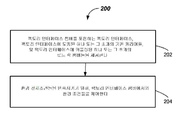
[00043] 이제 도 2를 참조하면, 전자 디바이스 프로세싱 시스템(예컨대, 전자 디바이스 프로세싱 시스템(100)) 내에서 기판들을 프로세싱하는 하나의 방법이 설명될 것이다. 방법(200)은, 202에서, 팩토리 인터페이스 챔버(예컨대, 팩토리 인터페이스 챔버(114C))를 갖는 팩토리 인터페이스(예컨대, 팩토리 인터페이스(114)), 및 팩토리 인터페이스에 도킹된 하나 또는 그 초과의 기판 캐리어들(예컨대, 기판 캐리어들(116)), 및 팩토리 인터페이스에 커플링된 하나 또는 그 초과의 로드 락 챔버들(예컨대, 로드 락 챔버들(112A, 112B))을 제공하는 단계를 포함한다.[00043] Referring now to FIG. 2, one method of processing substrates within an electronic device processing system (e.g., electronic device processing system 100) will be described. The
[00044] 방법(200)은, 204에서, 환경 전제 조건들을 만족시키기 위해, 환경 조건들을 제어하는 단계를 포함한다. 예컨대, 환경 전제 조건들을 만족시키기 위해, 환경 조건들을 제어하는 것은, (예컨대, 로드 락 챔버들(112A, 112B)의 외측 로드 락 슬릿 밸브들(138)을 개방시키는 것과 같은) 하나 또는 그 초과의 로드 락 챔버들, 또는 하나 또는 그 초과의 기판 캐리어 도어들(예컨대, 캐리어 도어들(116D)) 중 임의의 것을 개방시키기 전에, 발생할 수 있다.The
[00045] 본 발명의 하나 또는 그 초과의 실시예들에 따르면, 외측 로드 락 슬릿 밸브들(138)과 캐리어 도어들(116D) 중 하나 또는 그 초과는, 특정한 환경 전제 조건들이 만족되는 경우에, 개방될 수 있다. 예컨대, 일 예에서, 환경 전제 조건들은, 팩토리 인터페이스 챔버(114C)에서의 측정된 상대 습도(RH) 레벨이, 미리 정의된 상대 습도 레벨 임계치 아래로(예컨대, 1000 ppm의 습기 미만으로, 500 ppm의 습기 미만으로, 100 ppm의 습기 미만으로, 또는 심지어 더 낮게) 떨어지는 경우에, 만족될 수 있다. 발생되는 프로세싱에 따라, 다른 적합한 임계치들이 사용될 수 있다.[00045] According to one or more embodiments of the present invention, one or more of the outer load lock slit
[00046] 이전에-달성되지 않은(previously-failed) 환경 전제 조건들을 만족시키기 위해, 즉, 이전에-달성되지 않은 환경 전제 조건들 아래로 떨어지기 위해, 비활성 가스 공급부(118A)로부터 팩토리 인터페이스 챔버(114C) 내로 비활성 가스(예컨대, 건성 N2 가스 또는 다른 비활성 가스)가 유동될 수 있다. 비활성 가스 공급부(118A)는, 예컨대, 압력 하의 비활성 가스의 적합한 캐니스터(canister)일 수 있다. 팩토리 인터페이스 챔버(114C) 내로 제공되는 비활성 가스의 유량들은, 팩토리 인터페이스 챔버(114C) 내에 위치된 압력 센서(133), 및/또는 전달 라인 상의 적합한 유동 센서(미도시), 또는 이들 양자 모두에 의해, 모니터링될 수 있다. 제어기(125)에 의해 제공된 제어 신호들에 응답하여, 비활성 가스 공급부(118A)에 커플링된 밸브를 조정함으로써, 400 SLM 또는 그 초과의 유량들이 제공될 수 있다. 약 500 Pa 초과의 압력들이 팩토리 인터페이스 챔버(114C) 내에서 유지될 수 있다. 팩토리 인터페이스 챔버(114C) 내로의 비활성 가스(예컨대, N2 또는 다른 비활성 가스)의 유동은 상대 습도(RH) 레벨을 낮게 하도록 작용하고, 하나 또는 그 초과의 로드 락 챔버들(112A, 112B)의 외측 로드 락 슬릿 밸브들(138) 및/또는 캐리어 도어(116D)는, 상대 습도 임계치 값이 만족되는 경우에, 개방될 수 있다. 이는, 개방된 기판 캐리어들(116) 내의 기판들, 개방된 임의의 로드 락 챔버들(112A, 112B), 뿐만 아니라, 팩토리 인터페이스 챔버(114C)를 통과하는 임의의 기판들이, 적합하게 낮은 습도 환경에만 노출되는 것을 보장하는 것을 돕는다.[00046] In order to meet previously-failed environmental preconditions, that is, to fall below previously-not-achieved environmental preconditions, the
[00047] 다른 예에서, 환경 전제 조건들은, 예컨대, 산소 센서(132)에 의해 감지되는 바와 같은, 팩토리 인터페이스 챔버(114C)에서의 측정된 산소(O2) 레벨이, 미리 정의된 산소 임계치 레벨 아래로(예컨대, 50 ppm의 O2 미만으로, 10 ppm의 O2 미만으로, 5 ppm의 O2 미만으로, 또는 심지어 3 ppm의 O2 미만으로, 또는 심지어 더 낮게) 떨어지는 경우에, 만족될 수 있다. 발생되는 프로세싱에 따라, 다른 적합한 산소 레벨 임계치들이 사용될 수 있다. 팩토리 인터페이스 챔버(114C)에서의 미리 정의된 산소 임계치 레벨이 만족되지 않는 경우에, 제어기(125)는, 비활성 가스 공급부(118A)에 커플링된 밸브로의 제어 신호를 개시할 것이고, 제어기(125)에 의해 결정되는 바와 같이, 미리 정의된 산소 임계치 레벨이 만족될 때까지, 팩토리 인터페이스 챔버(114C) 내로 비활성 가스를 유동시킬 것이다. 미리 정의된 산소 임계치 레벨이 만족되는 경우에, 하나 또는 그 초과의 로드 락 챔버들(112A, 112B)의 외측 로드 락 슬릿 밸브들(138) 및/또는 캐리어 도어(116D)가 개방될 수 있다. 이는, 개방된 기판 캐리어들(116) 내의 기판들, 개방된 임의의 로드 락 챔버들(112A, 112B), 뿐만 아니라, 팩토리 인터페이스 챔버(114C)를 통과하는 임의의 기판들이, 비교적 낮은 산소 레벨들에 노출되는 것을 보장하는 것을 돕는다.[00047] In another example, environmental preconditions may be set so that the measured oxygen (O 2 ) level in the
[00048] 다른 예에서, 환경 전제 조건들은, 예컨대, 온도 센서(135)에 의해 감지되는 바와 같은, 냉각 스테이션(144)에서의 기판들(145)의 온도와 같은, 팩토리 인터페이스 챔버(114C)에서의 측정된 온도 레벨이, 미리 정의된 온도 임계치 레벨 아래로(예컨대, 섭씨 100 도 미만으로, 또는 심지어 더 낮게) 떨어지는 경우에, 만족될 수 있다. 미리 정의된 온도 임계치 레벨이 만족되면, 냉각된 기판들(145)은 운송을 위해 기판 캐리어(116) 내로 로딩될 수 있다. 냉각 스테이션(144)은, 냉각 플랫폼들, 비활성 가스 유동, 또는 이들의 조합들을 포함할 수 있다.[00048] In another example, the environmental prerequisites may be stored in the
[00049] 몇몇 실시예들에서, 팩토리 인터페이스(114)의 접근 도어(142)는, 특정한 환경 전제 조건들이 만족되는 경우에만, 개방될 수 있다. 예컨대, 환경 전제 조건들은, 안전한 것으로 결정된, 미리 결정된 산소 레벨 값을 초과하는, 팩토리 인터페이스 챔버(114C)에서의 산소 값에 도달하는 것을 포함할 수 있다. 산소 레벨 값은, 예컨대, 산소 센서(132)에 의해 감지될 수 있다. 도어 인터로크(140)(예컨대, 전기 기계적 로크)는, 제어기(125)가, 안전한 것으로 간주되는 미리 결정된 산소 레벨이 만족되었다고 결정하고, 도어 인터로크(140)를 개방시키기 위한 신호를 전송하지 않는 한, 접근 도어(142)가 개방되는 것을 방지할 수 있다. 달성되지 않은 경우에, 환경 전제 조건들은, 밸브로의 제어 신호를 통해, 공기 공급부(118B)로부터 팩토리 인터페이스 챔버(114C) 내로 공기를 유동시키고, 배기 도관(150)을 통해 팩토리 인터페이스 챔버(114C) 밖으로 비활성 가스를 유동시킴으로써, 만족될 수 있다. 공기 공급부(118B)는, 팬(fan) 또는 공기 펌프에 의해 제공되는 필터링된 공기의 공급부일 수 있다.[00049] In some embodiments, the
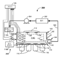
[00050] 도 3에서 도시된 바와 같이, 전자 디바이스 프로세싱 시스템(300)의 다른 실시예가 제공된다(메인프레임 하우징, 프로세싱 챔버들, 및 로드 락 챔버들은 명료성을 위해 도시되지 않음). 전자 디바이스 프로세싱 시스템(300)의 환경 제어 시스템(318)은, 이전에 언급된 컴포넌트들을 포함할 수 있지만, 또한, 비활성 가스 재순환을 포함할 수 있다. 특히, 팩토리 인터페이스(114)의 더 효율적인 환경 제어들을 제공하기 위해, 비활성 가스가 재활용될 수 있고 재사용될 수 있다. 예컨대, 도시된 실시예에서, 팩토리 인터페이스 챔버(114C)로부터의 비활성 가스는, 팩토리 인터페이스 챔버(114C)로부터 배기 도관(350)으로 배기될 수 있고, 습기-감소(moisture-reducing) 필터일 수 있고 또한 미립자들을 필터링할 수 있는 필터(352)를 통해 필터링될 수 있고, 그 후에, 펌프(354)에 의해, 비활성 가스 공급부(118A) 내로 펌핑되어 회귀될(pumped back) 수 있다. 필터(352)는, 흡수성 재료들의 다수의 층들을 포함할 수 있는 습기 흡수성(moisture absorbent) 필터일 수 있다. 그러나, 콘덴서(condenser)들 또는 다른 습기 제거기(moisture remover)들과 같은, 습기 함유량을 감소시키기 위한 다른 메커니즘들 또는 디바이스들이 사용될 수 있다. 몇몇 실시예들에서, 비활성 가스는 또한 냉각될 수 있다.[00050] As shown in FIG. 3, another embodiment of an electronic
[00051] 몇몇 실시예들에서, 비활성 가스 소비(consumption)가, 예컨대, 비활성 가스 공급부(118A)로부터의 전달 라인에서의 유동 센서(미도시)의 사용에 의해, 모니터링될 수 있고, 측정된 유량은, 팩토리 인터페이스 챔버(114C) 내의 특정된 RH 값의 도달과 상관될 수 있다. 비활성 가스 소비의 양이, 미리-설정된 제한 외부에 있는 경우에, 팩토리 인터페이스 챔버(114C)에서의 누설이, 예컨대, 오퍼레이터에 대한 메시지, 시각적인 표시자, 알람 등에 의해, 플래깅될(flagged) 수 있다. 선택적으로, 팩토리 인터페이스 챔버(114C) 내의 압력이, 미리-설정된 제한 외부에(예컨대, 아래에) 있는 경우에, 팩토리 인터페이스 챔버(114C)에서의 누설이, 위에서와 같이, 플래깅될 수 있다.[00051] In some embodiments, an inert gas consumption can be monitored, for example, by use of a flow sensor (not shown) at the transfer line from the
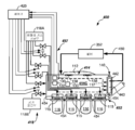
[00052] 도 4는, 환경 제어 시스템(418)을 포함하는 전자 디바이스 프로세싱 시스템(400)의 다른 실시예를 예시한다. 본 실시예에서, 환경 제어 시스템(418)은, 하나 또는 그 초과의 캐리어 퍼지 챔버들(454)의 환경 제어와 커플링된, 팩토리 인터페이스 챔버(414C)의 환경 제어의 조합을 포함한다. 그 외에, 본 실시예는, 캐리어 퍼지 시스템(452)이 제공되는 것을 제외하고, 도 3의 실시예와 유사하다.[00052] FIG. 4 illustrates another embodiment of an electronic
[00053] 팩토리 인터페이스 챔버(414C)의 환경 제어와 별도로 독립적인 사용이 가능할 수 있는 캐리어 퍼지 시스템(452)은, 가스 퍼지 시스템(457)을 포함한다. 가스 퍼지 시스템(457)은, 비활성 가스 공급부(예컨대, 비활성 가스 공급부(118A)), 및 비활성 가스 공급부에 커플링된 복수의 공급 도관들 및 밸브들을 포함한다. 가스 퍼지 시스템(457)의 복수의 공급 도관들 및 밸브들은, 제어기(425)로부터의 제어 신호들에 응답하여, 특정한 시간들에서, 비활성 가스를 캐리어 퍼지 챔버들(454)에 공급한다. 예컨대, 비활성 가스의 공급은, 기판 캐리어(116)로부터 팩토리 인터페이스 챔버(114C) 내로 기판들(545)을 이송하기 전에, 특정한 환경 전제 조건들을 만족시키기 위하여, 캐리어 퍼지 챔버(454) 및 기판 캐리어(116)의 환경(562)(도 5a)을 퍼징하기 위해, 기판 캐리어(116)의 캐리어 도어(116D)를 개방시킨 직후에, 캐리어 퍼지 챔버(454)에 제공될 수 있다.The
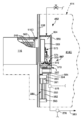
[00054] 이제, 팩토리 인터페이스(414)의 캐리어 퍼지 시스템(452)의 세부사항들 및 컴포넌트들 및 동작이 도 4, 도 5a, 및 도 5b에 관하여 설명될 것이다. 캐리어 퍼지 시스템(452)은, 퍼지 능력을 포함하여, 각각의 기판 캐리어(116)에 대해, 캐리어 퍼지 하우징(556)을 포함한다. 그러한 퍼지 능력은 기판 캐리어들(116)의 일부 또는 모두에 대해 포함될 수 있다. 캐리어 퍼지 하우징(556)은 각각의 캐리어 퍼지 챔버(454)의 일부를 형성한다. 캐리어 퍼지 하우징(556)은 팩토리 인터페이스(114)의 내부 벽(558)(예컨대, 전방 벽)의 표면에 대하여 밀봉될 수 있고, 캐리어 퍼지 챔버(454)를 형성할 수 있다. 캐리어 퍼지 하우징(556)은, 캐리어 도어(116D)가 개방된 동안에, 내부 벽(558)의 표면에 대하여 밀봉된 상태로 유지된다. 개스킷(gasket) 또는 O-링과 같은 임의의 적합한 밀봉이 사용될 수 있다.[00054] Now, the details and components and operation of the
[00055] 캐리어 퍼지 시스템(452)은, 도어 오프너(565) 및 도어 리트랙션(retraction) 메커니즘(567)의 동작을 통해, 기판 캐리어(116)의 캐리어 도어(116D)를 개방시킬 시에, 캐리어 퍼지 챔버(454) 내에 기판 캐리어(116)의 환경(562)을 수용하도록 적응된다. 캐리어 도어(116D)가 개방되면, 바람직하지 않은 레벨들의 O2 또는 습기를 함유할 수 있는 환경(562)이 팩토리 인터페이스 챔버(114C)에 진입하지 않도록, 캐리어 퍼지 챔버(454)의 퍼징이 발생할 수 있다. 캐리어 퍼지 챔버(454)의 퍼징은, 특정한 미리 정의된 환경 조건들이 만족될 때까지, 계속된다. 퍼징은, 가스 퍼지 시스템(457)으로부터 제공되는 비활성 가스를 통해 제공될 수 있다. 캐리어 퍼지 챔버(454) 내로 비활성 가스를 공급하는 가스 퍼지 시스템(457)의 도관(557C)으로부터의 출구들에, 하나 또는 그 초과의 디퓨저(diffuser)들(559)이 포함될 수 있다.The
[00056] 환경 조건들은, 예컨대, 미리 정의된 상대 습도 RH 임계치 레벨, 및/또는 미리 정의된 O2 임계치 레벨에 기초할 수 있다. 예컨대, 캐리어 퍼지 하우징(556)을 내부 벽(558)으로부터 떨어지게 리트랙팅하고, 캐리어 퍼지 하우징(556)을 하강시켜서, 로드/언로드 로봇(117)이 기판들(545)에 접근하고 기판들(545)을 제거하게 허용하기 전에, 미리 정의된 RH 임계치 레벨 미만(예컨대, 약 5 %의 습기 미만 - 약 50,000 ppm 미만)의 상대 습도가 추구될 수 있다. 산소 레벨이 환경 기준들인 경우에, 캐리어 퍼지 하우징(556)을 리트랙팅하고 하강시키기 전에, 미리 정의된 임계치 레벨 미만(예컨대, 약 500 ppm의 O2 미만)의 O2 임계치 레벨이 추구될 수 있다. 다른 미리 정의된 임계치 레벨들이 사용될 수 있다.[00056] Environmental conditions may be based, for example, on a predefined relative humidity RH threshold level, and / or a predefined O 2 threshold level. For example, the
[00057] 이러한 임계치 레벨들 중 하나 또는 양자 모두를 달성하기 위해, 제어기(425)와 상호연결된, 챔버 상대 습도 센서(576) 및/또는 챔버 산소 센서(578)가 제공될 수 있다. 챔버 상대 습도 센서(576) 및/또는 챔버 산소 센서(578)는, 캐리어 퍼지 하우징(556) 상에 있을 수 있거나, 팩토리 인터페이스 챔버(114C) 내에서 챔버 배기 도관(580)에 있을 수 있거나, 또는 심지어, 팩토리 인터페이스(114) 외부에, 예컨대 챔버 배기 도관(580) 상에 있을 수 있다. 가스 퍼지 시스템(457)으로부터의 비활성 가스에 의한 퍼징은, 환경 전제 조건들이 만족될 때까지, 계속될 수 있다. 몇몇 실시예들에서, 환경 전제 조건들이 만족되는 것을 보장하기 위해, 이전에-수행된 실험들에 기초한, 특정한 미리-설정된 시간 또는 볼륨에 대한 퍼징이 사용될 수 있다.[00057] To achieve one or both of these threshold levels, a chamber
[00058] 동작 시에, 캐리어 퍼지 하우징(556)은 도어 오프너(565)를 둘러싼다. 도어 오프너(565)는 캐리어 퍼지 하우징(556)의 내부 내에서 리트랙팅 가능하도록 적응된다. 도어 오프너(565)의 리트랙션은, 랙(rack) 및 피니언(pinion) 메커니즘(570) 및 선형 슬라이드(569)와 같은, 도어 리트랙션 메커니즘(567)에 의해 이루어질 수 있다. 랙 및 피니언 메커니즘(570)은, 랙(572), 피니언(574), 및 피니언(574)에 커플링된 구동 모터(575)를 포함할 수 있다. 제어기(425)로부터 구동 모터(575)로의 구동 신호들은, 캐리어 도어(116D)의 리트랙션, 및 캐리어 퍼지 챔버(454)에서의 환경과 환경(562)의 혼합을 야기한다. 통상적인 바와 같이, 캐리어 도어(116D)를 그래스핑(grasp)하고 개방시키기 위해, 도어 오프너(565) 상에서, 임의의 도어 언로크 및 그래스프 메커니즘(573)이 사용될 수 있다.[00058] In operation, the
[00059] 캐리어 퍼지 하우징(556)에 의한, 내부 벽(558)에 대한 폐쇄(예컨대, 밀봉), 및 내부 벽(558)으로부터의 리트랙션은, 하우징 구동 시스템(581) 및 슬라이드 메커니즘(582)에 의해 제공될 수 있다. 슬라이드 메커니즘(582)은, 엘리베이터(585)에 부착된 지지 프레임(584)에 관하여, 내부 벽(558)을 향하는 그리고 내부 벽(558)으로부터 떨어지는 선형 모션을 허용한다. 하우징 구동 시스템(581)은, 내부 벽(558)을 향하는 그리고 내부 벽(558)으로부터 떨어지는 모션을 야기하기 위해, 적합한 모터 및 전달 메커니즘을 포함할 수 있다. 도시된 실시예에서, 캐리어 퍼지 하우징(556)에 커플링된 하우징 랙(586), 하우징 피니언(588), 및 하우징 구동 모터(589)를 포함하는 랙 및 피니언 메커니즘이 도시된다. 하우징 구동 모터(589)를 구동시키는 것은, 내부 벽(558) 및 엘리베이터(585)에 관하여, 수평으로 안쪽으로 또는 바깥쪽으로(in or out), 캐리어 퍼지 하우징(556)을 평행 이동시킨다.The retraction from the
[00060] 캐리어 퍼지 하우징(556)의 하강은 엘리베이터(585)에 의해 제공될 수 있다. 엘리베이터(585)는, 캐리어 퍼지 하우징(556)의 수직 모션을 제공하기 위한 임의의 적합한 메커니즘 구조를 포함할 수 있다. 예컨대, 도시된 바와 같이, 엘리베이터(585)는, 베어링 슬라이드(591), 레일(592), 및 마운팅 블록(mounting block)들(593)을 포함하는 선형 베어링 어셈블리(590)를 포함한다. 마운팅 블록들(593)은 내부 벽(558)에 레일(592)을 체결(fasten)시킬 수 있다. 베어링 슬라이드(591)는 수직 액추에이터(594)에 체결될 수 있다. 수직 액추에이터 레일(595)이 또한 제공될 수 있고, 내부 벽(558)에 체결될 수 있다. 수직 액추에이터(594)의 작동은, 지지 프레임(584) 및 커플링된 캐리어 퍼지 하우징(556)을 상승시키거나 또는 하강시키는, 수직 액추에이터 레일(595)에 관한 수직 모션을 야기한다. 수직 액추에이터(594)는, 공압식, 전기식 등과 같은 임의의 적합한 액추에이터 타입일 수 있다. 따라서, 도어 그래스프 및 언로크 메커니즘(573)의 동작이 캐리어 도어(116D)를 그래스핑하고 개방시키고, 랙 및 피니언 메커니즘(570)이 캐리어 도어(116D)를 리트랙팅하고, 캐리어 퍼지 시스템(452)이, 환경 전제 조건들을 만족시키기 위해, 캐리어 퍼지 챔버(454)를 퍼징하고, 하우징 구동 시스템(581)이 캐리어 퍼지 하우징(556)을 리트랙팅하고, 엘리베이터(585)가, 로드/언로드 로봇(117)이 기판 캐리어(116)에서의 기판들(545)에 접근할 수 있도록, 캐리어 도어(116D) 및 캐리어 퍼지 하우징(556)을 하강시키는 것이 명백해야 한다.[00060] The descent of the
[00061] 다시 도 4를 참조하면, 환경 제어 시스템(418)은 이전에 언급된 컴포넌트들을 포함할 수 있고, 또한, 비활성 가스 재순환을 포함할 수 있다. 예컨대, 비활성 가스는, 팩토리 인터페이스 챔버(414C)로부터 배기 도관(450)으로 배기될 수 있고, 습기-감소 필터일 수 있지만, 또한 미립자들을 필터링할 수 있고, 위에서 논의된 타입일 수 있는 필터(352)를 통해 필터링될 수 있다. 본 실시예에서, 필터링된 비활성 가스는, 팩토리 인터페이스 챔버(414C) 내로 바로 재순환되어 회귀될 수 있다.[00061] Referring again to FIG. 4, the
[00062] 예컨대, 도시된 실시예에서, 배기 순환 루트의 일부는 챔버 도어(442)를 통하는 것일 수 있다. 예컨대, 팩토리 인터페이스 챔버(414C)로부터의 배기는, 챔버 도어(442)에 형성된 채널(443)(예컨대, 덕트) 내로 진입할 수 있다. 몇몇 실시예들에서, 채널(443)은, 챔버 도어(442)의 바닥에 또는 그 근처에, 팩토리 인터페이스 챔버(414C)로부터의 입구를 가질 수 있고, 팩토리 인터페이스 챔버(414C)의 상부 부분 내에 있을 수 있는 필터(352) 위로 진행될 수 있다. 따라서, 채널(443)은 배기 도관(450)의 일부일 수 있다. 몇몇 실시예들에서, 채널(443)과 같은 내부 채널을 포함하는, 챔버 도어(442)와 유사한 도어가, 팩토리 인터페이스(414)의 다른 측 상에 제공될 수 있다.[00062] For example, in the illustrated embodiment, a portion of the exhaust circulation route may be through the
[00063] 이제 도 6을 참조하면, 전자 디바이스 프로세싱 시스템(예컨대, 전자 디바이스 프로세싱 시스템(400)) 내에서 기판들을 프로세싱하는 다른 방법이 설명될 것이다. 방법(600)은, 602에서, 팩토리 인터페이스 챔버(예컨대, 팩토리 인터페이스 챔버(414C))를 갖는 팩토리 인터페이스(예컨대, 팩토리 인터페이스(414)), 팩토리 인터페이스에 도킹된 하나 또는 그 초과의 기판 캐리어들(예컨대, 기판 캐리어들(116)), 팩토리 인터페이스 챔버 내의 하나 또는 그 초과의 캐리어 퍼지 챔버들(예컨대, 캐리어 퍼지 챔버들(454)), 및 팩토리 인터페이스에 커플링된 하나 또는 그 초과의 로드 락 챔버들(예컨대, 로드 락 장치(112)의 로드 락 챔버들(112A, 112B))을 제공하는 단계를 포함한다.[00063] Referring now to FIG. 6, another method of processing substrates within an electronic device processing system (e.g., electronic device processing system 400) will be described. The
[00064] 방법(600)은, 604에서, 팩토리 인터페이스(예컨대, 팩토리 인터페이스(414)) 내의 그리고 하나 또는 그 초과의 캐리어 퍼지 챔버들(예컨대, 캐리어 퍼지 챔버들(454)) 내의 환경 조건들을 제어하는 단계를 포함한다. 팩토리 인터페이스 내의 환경 조건들을 제어하는 것은, 하나 또는 그 초과의 로드 락 챔버들(예컨대, 로드 락 챔버들(112A, 112B)의 외측 로드 락 슬릿 밸브들(138)) 중 임의의 것, 또는 하나 또는 그 초과의 기판 캐리어 도어들(예컨대, 캐리어 도어들(116D)) 중 임의의 것의 개방을 허용하기 전에, 팩토리 인터페이스 챔버에서 환경 전제 조건들을 만족시키는 것을 포함할 수 있다. 하나 또는 그 초과의 캐리어 퍼지 챔버들(예컨대, 캐리어 퍼지 챔버들(454)) 내의 환경 조건들을 제어하는 것은, 위에서 논의된 바와 같이, 캐리어 퍼지 하우징(556)의 리트랙션 및 하강을 통해 개봉(unsealing)하기 전에, (예컨대, RH 임계치 레벨 또는 O2 임계치 레벨에 대한) 특정한 환경 전제 조건들을 만족시키는 것을 포함할 수 있다. 본 발명의 실시예들에 따른 그러한 환경 제어들을 제공하는 것은, 비교적 높은 O2 레벨들을 갖는 환경들 또는 비교적 습한 환경들과 같은, 유해할 수 있는 환경 조건들에 대한, 프로세싱 후에 로드 락 챔버들(112A, 112B)에서 빠져나가는 또는 기판 캐리어들(116)에서 빠져나가는 기판들(545)의 노출을 감소시킬 수 있다.The
[00065] 전술한 설명은 본 발명의 단지 예시적인 실시예들을 개시한다. 본 발명의 범위 내에 속하는, 위에서 개시된 장치, 시스템들, 및 방법들의 변형들이, 당업자에게 쉽게 명백하게 될 것이다. 따라서, 본 발명이 예시적인 실시예들에 관련하여 개시되었지만, 다른 실시예들이, 다음의 청구항들에 의해 정의되는 바와 같은, 본 발명의 범위 내에 속할 수 있다는 것이 이해되어야 한다.[00065] The foregoing description discloses only exemplary embodiments of the invention. Modifications of the above-disclosed apparatus, systems, and methods within the scope of the present invention will be readily apparent to those skilled in the art. Thus, while the present invention has been disclosed with respect to exemplary embodiments, it is to be understood that other embodiments may be within the scope of the invention, as defined by the following claims.
Claims (20)
팩토리 인터페이스 챔버를 포함하는 팩토리 인터페이스;
상기 팩토리 인터페이스에 커플링된 로드 락 장치;
상기 팩토리 인터페이스에 커플링된 하나 또는 그 초과의 기판 캐리어들; 및
상기 팩토리 인터페이스에 커플링된 환경 제어 시스템
을 포함하며,
상기 환경 제어 시스템은:
상기 팩토리 인터페이스 챔버 내로의 비활성 가스의 양을 제어하고; 그리고
상기 팩토리 인터페이스 챔버로부터 배기되는 상기 비활성 가스를 다시 상기 팩토리 인터페이스 챔버 내로 재순환시키도록 동작하는,
전자 디바이스 프로세싱 시스템.An electronic device processing system,
A factory interface including a factory interface chamber;
A load lock device coupled to the factory interface;
One or more substrate carriers coupled to the factory interface; And
An environmental control system coupled to the factory interface
/ RTI >
The environment control system comprising:
Controlling the amount of inert gas into the factory interface chamber; And
And to recycle the inert gas exhausted from the factory interface chamber back into the factory interface chamber.
Electronic device processing system.
배기 도관을 더 포함하고, 상기 비활성 가스는 상기 배기 도관을 거쳐 적어도 부분적으로 재순환되는,
전자 디바이스 프로세싱 시스템.The method according to claim 1,
Further comprising an exhaust conduit, wherein the inert gas is at least partially recirculated through the exhaust conduit,
Electronic device processing system.
상기 배기 도관에 직렬로 연결된 필터를 더 포함하는,
전자 디바이스 프로세싱 시스템.3. The method of claim 2,
Further comprising a filter coupled in series with the exhaust conduit,
Electronic device processing system.
상기 필터는 미립자들을 필터링하도록 구성되는,
전자 디바이스 프로세싱 시스템.The method of claim 3,
Wherein the filter is configured to filter particulates,
Electronic device processing system.
상기 필터는 습기-감소(moisture-reducing) 필터인,
전자 디바이스 프로세싱 시스템.The method of claim 3,
Wherein the filter is a moisture-reducing filter,
Electronic device processing system.
상기 필터는 습기-흡수성(moisture-absorbent) 필터인,
전자 디바이스 프로세싱 시스템.The method of claim 3,
Wherein the filter is a moisture-absorbent filter,
Electronic device processing system.
상기 필터는 상기 팩토리 인터페이스 챔버 내에 있는,
전자 디바이스 프로세싱 시스템.The method of claim 3,
Said filter being located within said factory interface chamber,
Electronic device processing system.
상기 팩토리 인터페이스 챔버 상의 챔버 도어; 및
상기 챔버 도어 내의 채널
을 더 포함하고, 상기 채널은 상기 팩토리 인터페이스 챔버로부터의 입구를 가지며, 상기 채널은 상기 배기 도관에 커플링되는,
전자 디바이스 프로세싱 시스템.3. The method of claim 2,
A chamber door on the factory interface chamber; And
The channel in the chamber door
Wherein the channel has an inlet from the factory interface chamber and the channel is coupled to the exhaust conduit,
Electronic device processing system.
상기 챔버 도어는 바닥을 가지며, 상기 채널의 입구는 상기 챔버 도어의 상기 바닥에 인접한,
전자 디바이스 프로세싱 시스템.9. The method of claim 8,
The chamber door having a bottom and an inlet of the channel adjacent the bottom of the chamber door,
Electronic device processing system.
상기 배기 도관 내에 직렬로 연결된 필터를 더 포함하고, 상기 챔버 도어와 상기 필터 사이의 상기 배기 도관은 상기 필터 위에서 진행하는,
전자 디바이스 프로세싱 시스템.10. The method of claim 9,
Further comprising a filter coupled in series within the exhaust conduit, wherein the exhaust conduit between the chamber door and the filter is a < RTI ID = 0.0 >
Electronic device processing system.
팩토리 인터페이스 챔버를 포함하는 팩토리 인터페이스;
상기 팩토리 인터페이스에 커플링된 로드 락 장치;
상기 팩토리 인터페이스에 커플링된 하나 또는 그 초과의 기판 캐리어들;
상기 팩토리 인터페이스 챔버에 커플링되는 비활성 가스 공급부;
상기 팩토리 인터페이스 챔버 내로의 비활성 가스 유동 및 상기 팩토리 인터페이스 챔버 내의 가스 압력 중 적어도 하나를 나타내는 하나 또는 그 초과의 신호들을 생성하도록 동작하는 하나 또는 그 초과의 센서들; 및
상기 하나 또는 그 초과의 센서들에 커플링되는 제어기를 더 포함하고,
상기 제어기는:
상기 하나 또는 그 초과의 신호들을 모니터링하고; 그리고
상기 하나 또는 그 초과의 신호들이 미리-설정된 제한 밖에 있는 경우에 응답하여 신호를 생성하는 것에 의해
누설을 결정하도록 동작하는,
전자 디바이스 프로세싱 시스템.An electronic device processing system,
A factory interface including a factory interface chamber;
A load lock device coupled to the factory interface;
One or more substrate carriers coupled to the factory interface;
An inert gas supply coupled to the factory interface chamber;
One or more sensors operative to generate one or more signals indicative of at least one of an inert gas flow into the factory interface chamber and a gas pressure in the factory interface chamber; And
Further comprising a controller coupled to said one or more sensors,
The controller comprising:
Monitoring said one or more signals; And
By generating a signal in response to the one or more signals being outside a pre-established limit
Operating to determine leakage,
Electronic device processing system.
상기 비활성 가스 공급부와 상기 팩토리 인터페이스 챔버 사이에 커플링되는 전달 라인을 더 포함하고, 상기 하나 또는 그 초과의 센서들은 상기 전달 라인 내의 유동 센서인,
전자 디바이스 프로세싱 시스템.12. The method of claim 11,
Further comprising a delivery line coupled between the inert gas supply and the factory interface chamber, wherein the one or more sensors are flow sensors in the delivery line,
Electronic device processing system.
상기 유동 센서는 상기 전달 라인을 통해 비활성 가스를 나타내는 하나 또는 그 초과의 신호들을 생성하고, 신호를 생성하는 것은 상기 비활성 가스 유동이 미리-설정된 제한 밖에 있는 경우에 응답하여 신호를 생성하는 것을 포함하는,
전자 디바이스 프로세싱 시스템.13. The method of claim 12,
Wherein the flow sensor generates one or more signals representative of an inert gas through the delivery line and generating a signal comprises generating a signal in response to the inactive gas flow being outside a pre- ,
Electronic device processing system.
상기 하나 또는 그 초과의 센서들은 상기 팩토리 인터페이스 챔버 내에 위치된 압력 센서를 포함하는,
전자 디바이스 프로세싱 시스템.12. The method of claim 11,
Said one or more sensors including a pressure sensor located within said factory interface chamber,
Electronic device processing system.
상기 압력 센서는 상기 팩토리 인터페이스 챔버 내의 압력을 나타내는 하나 또는 그 초과의 신호들을 생성하고, 신호를 생성하는 것은 상기 압력이 미리-설정된 제한 밖에 있는 경우에 응답하여 신호를 생성하는 것을 포함하는,
전자 디바이스 프로세싱 시스템.15. The method of claim 14,
Wherein the pressure sensor generates one or more signals representative of a pressure within the factory interface chamber and generating a signal comprises generating a signal in response to the pressure being outside a pre-
Electronic device processing system.
신호를 생성하는 것은 상기 압력이 미리-설정된 제한 아래에 있는 경우에 응답하여 신호를 생성하는 것을 포함하는,
전자 디바이스 프로세싱 시스템.16. The method of claim 15,
Generating a signal comprises generating a signal in response to the pressure being below a pre-
Electronic device processing system.
상기 미리-설정된 제한은 500 Pa인,
전자 디바이스 프로세싱 시스템.17. The method of claim 16,
Wherein the pre-set limit is 500 Pa,
Electronic device processing system.
상기 비활성 가스 공급부 및 상기 팩토리 인터페이스 챔버 사이에 커플링되는 전달 라인을 더 포함하고, 상기 하나 또는 그 초과의 센서들은 상기 전달 라인 내의 유동 센서이고, 하나 또는 그 초과의 센서들은 상기 팩토리 인터페이스 챔버 내의 압력 센서인,
전자 디바이스 프로세싱 시스템.12. The method of claim 11,
Further comprising a transfer line coupled between the inert gas supply and the factory interface chamber, wherein the one or more sensors are flow sensors in the delivery line, one or more sensors are located within the factory interface chamber The sensor,
Electronic device processing system.
신호를 생성하는 것은 상기 압력이 미리-설정된 제한 아래에 있거나 또는 상기 비활성 가스 유동이 미리-설정된 제한 밖에 있는 경우에 응답하여 신호를 생성하는 것을 포함하는,
전자 디바이스 프로세싱 시스템.19. The method of claim 18,
Generating a signal comprises generating a signal in response to the pressure being below a pre-set limit or when the inert gas flow is outside a pre-
Electronic device processing system.
상기 비활성 가스는 아르곤(Ar), 질소(N2) 가스, 또는 헬륨(He)을 포함하는,
전자 디바이스 프로세싱 시스템.19. The method of claim 18,
The inert gas containing argon (Ar), nitrogen (N 2) gas or helium (He),
Electronic device processing system.
Priority Applications (1)
| Application Number | Priority Date | Filing Date | Title |
|---|---|---|---|
| KR1020197024815A KR102297447B1 (en) | 2013-08-12 | 2014-08-11 | Substrate processing systems, apparatus, and methods with factory interface environmental controls |
Applications Claiming Priority (3)
| Application Number | Priority Date | Filing Date | Title |
|---|---|---|---|
| US201361865046P | 2013-08-12 | 2013-08-12 | |
| US61/865,046 | 2013-08-12 | ||
| PCT/US2014/050561 WO2015023591A1 (en) | 2013-08-12 | 2014-08-11 | Substrate processing systems, apparatus, and methods with factory interface environmental controls |
Related Parent Applications (1)
| Application Number | Title | Priority Date | Filing Date |
|---|---|---|---|
| KR1020167006455A Division KR20160043027A (en) | 2013-08-12 | 2014-08-11 | Substrate processing systems, apparatus, and methods with factory interface environmental controls |
Related Child Applications (1)
| Application Number | Title | Priority Date | Filing Date |
|---|---|---|---|
| KR1020197024815A Division KR102297447B1 (en) | 2013-08-12 | 2014-08-11 | Substrate processing systems, apparatus, and methods with factory interface environmental controls |
Publications (2)
| Publication Number | Publication Date |
|---|---|
| KR20180098421A true KR20180098421A (en) | 2018-09-03 |
| KR102234464B1 KR102234464B1 (en) | 2021-03-30 |
Family
ID=52449296
Family Applications (6)
| Application Number | Title | Priority Date | Filing Date |
|---|---|---|---|
| KR1020197024815A Active KR102297447B1 (en) | 2013-08-12 | 2014-08-11 | Substrate processing systems, apparatus, and methods with factory interface environmental controls |
| KR1020167006455A Ceased KR20160043027A (en) | 2013-08-12 | 2014-08-11 | Substrate processing systems, apparatus, and methods with factory interface environmental controls |
| KR1020227028568A Ceased KR20220120714A (en) | 2013-08-12 | 2014-08-11 | Substrate processing systems, apparatus, and methods with factory interface environmental controls |
| KR1020247033706A Pending KR20240152961A (en) | 2013-08-12 | 2014-08-11 | Substrate processing systems, apparatus, and methods with factory interface environmental controls |
| KR1020187024379A Active KR102234464B1 (en) | 2013-08-12 | 2014-08-11 | Substrate processing systems, apparatus, and methods with factory interface environmental controls |
| KR1020217027565A Active KR102435429B1 (en) | 2013-08-12 | 2014-08-11 | Substrate processing systems, apparatus, and methods with factory interface environmental controls |
Family Applications Before (4)
| Application Number | Title | Priority Date | Filing Date |
|---|---|---|---|
| KR1020197024815A Active KR102297447B1 (en) | 2013-08-12 | 2014-08-11 | Substrate processing systems, apparatus, and methods with factory interface environmental controls |
| KR1020167006455A Ceased KR20160043027A (en) | 2013-08-12 | 2014-08-11 | Substrate processing systems, apparatus, and methods with factory interface environmental controls |
| KR1020227028568A Ceased KR20220120714A (en) | 2013-08-12 | 2014-08-11 | Substrate processing systems, apparatus, and methods with factory interface environmental controls |
| KR1020247033706A Pending KR20240152961A (en) | 2013-08-12 | 2014-08-11 | Substrate processing systems, apparatus, and methods with factory interface environmental controls |
Family Applications After (1)
| Application Number | Title | Priority Date | Filing Date |
|---|---|---|---|
| KR1020217027565A Active KR102435429B1 (en) | 2013-08-12 | 2014-08-11 | Substrate processing systems, apparatus, and methods with factory interface environmental controls |
Country Status (6)
| Country | Link |
|---|---|
| US (4) | US10192765B2 (en) |
| JP (6) | JP6526660B6 (en) |
| KR (6) | KR102297447B1 (en) |
| CN (6) | CN105453246A (en) |
| TW (6) | TWI902104B (en) |
| WO (1) | WO2015023591A1 (en) |
Families Citing this family (57)
| Publication number | Priority date | Publication date | Assignee | Title |
|---|---|---|---|---|
| CN105453246A (en) | 2013-08-12 | 2016-03-30 | 应用材料公司 | Substrate processing system, apparatus and method with factory interface environmental control |
| US9698041B2 (en) | 2014-06-09 | 2017-07-04 | Applied Materials, Inc. | Substrate temperature control apparatus including optical fiber heating, substrate temperature control systems, electronic device processing systems, and methods |
| JP6608923B2 (en) * | 2014-07-02 | 2019-11-20 | アプライド マテリアルズ インコーポレイテッド | TEMPERATURE CONTROL DEVICE INCLUDING HEATING WITH OPTICAL FIBER PATHED TO GROOVE, SUBSTRATE TEMPERATURE CONTROL SYSTEM, ELECTRONIC DEVICE PROCESSING SYSTEM, AND PROCESSING METHOD |
| JP6822953B2 (en) * | 2014-11-25 | 2021-01-27 | アプライド マテリアルズ インコーポレイテッドApplied Materials,Incorporated | Substrate processing systems, equipment, and methods with environmental control of substrate carriers and purge chambers |
| JP6458595B2 (en) * | 2015-03-27 | 2019-01-30 | 東京エレクトロン株式会社 | Film forming apparatus, film forming method, and storage medium |
| WO2016190982A1 (en) | 2015-05-22 | 2016-12-01 | Applied Materials, Inc | Substrate carrier door assemblies, substrate carriers, and methods including magnetic door seal |
| TWI727562B (en) * | 2015-08-04 | 2021-05-11 | 日商昕芙旎雅股份有限公司 | Load port |
| TWI878060B (en) | 2015-08-04 | 2025-03-21 | 日商昕芙旎雅股份有限公司 | Door opening and closing system and loading port having door opening and closing system |
| TWI780030B (en) * | 2015-10-05 | 2022-10-11 | 德商布魯克斯Ccs有限公司 | Method and system for forming a clean environment for semiconductor substrates with low humidity level |
| US10520371B2 (en) | 2015-10-22 | 2019-12-31 | Applied Materials, Inc. | Optical fiber temperature sensors, temperature monitoring apparatus, and manufacturing methods |
| US10119191B2 (en) | 2016-06-08 | 2018-11-06 | Applied Materials, Inc. | High flow gas diffuser assemblies, systems, and methods |
| US10684159B2 (en) | 2016-06-27 | 2020-06-16 | Applied Materials, Inc. | Methods, systems, and apparatus for mass flow verification based on choked flow |
| JP6903883B2 (en) * | 2016-09-09 | 2021-07-14 | Tdk株式会社 | Container cleaning device |
| JP6842156B2 (en) * | 2016-10-25 | 2021-03-17 | 株式会社システック | Explosion-proof constant temperature bath |
| US10159169B2 (en) | 2016-10-27 | 2018-12-18 | Applied Materials, Inc. | Flexible equipment front end module interfaces, environmentally-controlled equipment front end modules, and assembly methods |
| US10453727B2 (en) | 2016-11-10 | 2019-10-22 | Applied Materials, Inc. | Electronic device manufacturing load port apparatus, systems, and methods |
| US10262884B2 (en) * | 2016-11-10 | 2019-04-16 | Applied Materials, Inc. | Systems, apparatus, and methods for an improved load port |
| US10541165B2 (en) | 2016-11-10 | 2020-01-21 | Applied Materials, Inc. | Systems, apparatus, and methods for an improved load port backplane |
| US10453726B2 (en) | 2016-11-10 | 2019-10-22 | Applied Materials, Inc. | Electronic device manufacturing load port apparatus, systems, and methods |
| US10741432B2 (en) * | 2017-02-06 | 2020-08-11 | Applied Materials, Inc. | Systems, apparatus, and methods for a load port door opener |
| JP7158133B2 (en) * | 2017-03-03 | 2022-10-21 | アプライド マテリアルズ インコーポレイテッド | Atmosphere-controlled transfer module and processing system |
| US10446428B2 (en) | 2017-03-14 | 2019-10-15 | Applied Materials, Inc. | Load port operation in electronic device manufacturing apparatus, systems, and methods |
| US10796935B2 (en) * | 2017-03-17 | 2020-10-06 | Applied Materials, Inc. | Electronic device manufacturing systems, methods, and apparatus for heating substrates and reducing contamination in loadlocks |
| US11133208B2 (en) * | 2017-05-31 | 2021-09-28 | Tdk Corporation | EFEM and method of introducing dry air thereinto |
| US10388547B2 (en) * | 2017-06-23 | 2019-08-20 | Applied Materials, Inc. | Side storage pods, equipment front end modules, and methods for processing substrates |
| TWI717034B (en) | 2017-06-23 | 2021-01-21 | 美商應用材料股份有限公司 | Side storage pod, electronic device processing systems, and methods of processing substrates |
| US10361099B2 (en) * | 2017-06-23 | 2019-07-23 | Applied Materials, Inc. | Systems and methods of gap calibration via direct component contact in electronic device manufacturing systems |
| US10763134B2 (en) * | 2018-02-27 | 2020-09-01 | Applied Materials, Inc. | Substrate processing apparatus and methods with factory interface chamber filter purge |
| JP7125589B2 (en) * | 2018-03-15 | 2022-08-25 | シンフォニアテクノロジー株式会社 | EFEM system and gas supply method in EFEM system |
| US10403514B1 (en) * | 2018-04-12 | 2019-09-03 | Asm Ip Holding B.V. | Substrate transporting system, storage medium and substrate transporting method |
| US20190362989A1 (en) * | 2018-05-25 | 2019-11-28 | Applied Materials, Inc. | Substrate manufacturing apparatus and methods with factory interface chamber heating |
| JP6876020B2 (en) * | 2018-07-27 | 2021-05-26 | 株式会社Kokusai Electric | Substrate processing equipment and semiconductor equipment manufacturing methods and programs |
| US10529602B1 (en) * | 2018-11-13 | 2020-01-07 | Applied Materials, Inc. | Method and apparatus for substrate fabrication |
| US11189511B2 (en) * | 2018-10-26 | 2021-11-30 | Applied Materials, Inc. | Side storage pods, equipment front end modules, and methods for operating EFEMs |
| US11373891B2 (en) * | 2018-10-26 | 2022-06-28 | Applied Materials, Inc. | Front-ducted equipment front end modules, side storage pods, and methods of operating the same |
| US11244844B2 (en) * | 2018-10-26 | 2022-02-08 | Applied Materials, Inc. | High flow velocity, gas-purged, side storage pod apparatus, assemblies, and methods |
| KR102728796B1 (en) * | 2019-03-20 | 2024-11-12 | 삼성전자주식회사 | Heat treatment apparatus for semiconductor substrate |
| JP7221110B2 (en) * | 2019-03-28 | 2023-02-13 | 株式会社Screenホールディングス | Substrate processing equipment |
| TWI737996B (en) * | 2019-05-16 | 2021-09-01 | 華景電通股份有限公司 | Load port monitoring system and monitoring method thereof |
| JP7379042B2 (en) * | 2019-09-20 | 2023-11-14 | 東京エレクトロン株式会社 | Vacuum transfer device and vacuum transfer device control method |
| CN111090295A (en) * | 2019-12-31 | 2020-05-01 | 北京海岚科技有限公司 | Control method and control system for environmental parameters in EFEM (electronic flash memory) |
| CN113113326B (en) * | 2020-01-10 | 2024-12-27 | 台湾积体电路制造股份有限公司 | Semiconductor processing equipment |
| US20210407837A1 (en) * | 2020-06-30 | 2021-12-30 | Applied Materials, Inc. | Robot apparatus and systems, and methods for transporting substrates in electronic device manufacturing |
| US11810805B2 (en) * | 2020-07-09 | 2023-11-07 | Applied Materials, Inc. | Prevention of contamination of substrates during gas purging |
| US11996307B2 (en) * | 2020-12-23 | 2024-05-28 | Applied Materials, Inc. | Semiconductor processing tool platform configuration with reduced footprint |
| JP7154325B2 (en) * | 2021-01-20 | 2022-10-17 | 株式会社Kokusai Electric | SUBSTRATE PROCESSING APPARATUS, SEMICONDUCTOR DEVICE MANUFACTURING METHOD AND PROGRAM |
| US12159802B2 (en) * | 2021-03-04 | 2024-12-03 | Applied Materials, Inc. | Shortened load port for factory interface |
| US11854851B2 (en) * | 2021-03-05 | 2023-12-26 | Taiwan Semiconductor Manufacturing Company, Ltd. | Interface tool |
| WO2022201831A1 (en) * | 2021-03-25 | 2022-09-29 | 株式会社Screenホールディングス | Exhaust control method for processing liquid cabinet and substrate processing device |
| KR102592612B1 (en) | 2021-08-24 | 2023-10-24 | (주)옵토레인 | Molecular diagnostic cartridge |
| JP7698198B2 (en) * | 2021-08-26 | 2025-06-25 | シンフォニアテクノロジー株式会社 | EFEM, inert gas supply control method |
| JP7430677B2 (en) * | 2021-09-21 | 2024-02-13 | 株式会社Kokusai Electric | Substrate processing equipment, semiconductor device manufacturing method and program |
| US11756925B2 (en) * | 2021-10-22 | 2023-09-12 | Applied Materials, Inc. | Methods and apparatus for vacuum processing a substrate |
| KR20250086703A (en) * | 2022-10-10 | 2025-06-13 | 램 리써치 코포레이션 | Purge of toxic and corrosive materials from substrate processing chambers |
| KR20250073237A (en) * | 2022-11-07 | 2025-05-27 | 주식회사 히타치하이테크 | Wafer return device |
| US20240153787A1 (en) * | 2022-11-07 | 2024-05-09 | Taiwan Semiconductor Manufacturing Co., Ltd. | Control of environment within processing modules |
| KR102925708B1 (en) * | 2023-12-18 | 2026-02-10 | (주)아이디온 | System and method of real time monitering wafer transfer carrier for semiconductor process |
Citations (4)
| Publication number | Priority date | Publication date | Assignee | Title |
|---|---|---|---|---|
| JPH07138092A (en) * | 1993-11-15 | 1995-05-30 | Nec Corp | Molecular-beam apparatus for growing crystal |
| KR100505061B1 (en) * | 2003-02-12 | 2005-08-01 | 삼성전자주식회사 | Substrate transfer module |
| JP2009117554A (en) * | 2007-11-05 | 2009-05-28 | Hitachi Kokusai Electric Inc | Substrate processing equipment |
| WO2012133441A1 (en) * | 2011-03-28 | 2012-10-04 | 株式会社日立国際電気 | Substrate processing device, method for manufacturing semiconductor device, and substrate processing method |
Family Cites Families (116)
| Publication number | Priority date | Publication date | Assignee | Title |
|---|---|---|---|---|
| US3688540A (en) * | 1969-07-29 | 1972-09-05 | Superior Tube Co | Tube rolling mill employing a tapered mandrel and a cluster of rolls that each have specially designed tube contacting grooves |
| JPS62222625A (en) * | 1986-03-25 | 1987-09-30 | Shimizu Constr Co Ltd | Semiconductor manufacturing equipment |
| US5186594A (en) | 1990-04-19 | 1993-02-16 | Applied Materials, Inc. | Dual cassette load lock |
| JPH05326421A (en) * | 1992-05-20 | 1993-12-10 | Fujitsu Ltd | Film-formation method |
| JPH0634479A (en) | 1992-07-16 | 1994-02-08 | Toshiba Ceramics Co Ltd | Method and device for detecting gas leak from heat-treatment furnace for semiconductor |
| US5527390A (en) * | 1993-03-19 | 1996-06-18 | Tokyo Electron Kabushiki | Treatment system including a plurality of treatment apparatus |
| KR100221983B1 (en) * | 1993-04-13 | 1999-09-15 | 히가시 데쓰로 | A treating apparatus for semiconductor process |
| JPH07226382A (en) * | 1994-02-10 | 1995-08-22 | Tokyo Electron Ltd | Heat treatment equipment |
| JP2885142B2 (en) * | 1995-08-16 | 1999-04-19 | 日本電気株式会社 | Vacuum processing apparatus and method for detecting atmospheric contamination in vacuum processing apparatus |
| JP2806919B2 (en) | 1996-12-25 | 1998-09-30 | 日本電気ファクトリエンジニアリング株式会社 | Constant temperature bath |
| JPH10270535A (en) | 1997-03-25 | 1998-10-09 | Nikon Corp | Moving stage device and circuit device manufacturing method using the stage device |
| JP3839555B2 (en) * | 1997-06-05 | 2006-11-01 | 高砂熱学工業株式会社 | Locally sealed cleaning device |
| JP3425592B2 (en) * | 1997-08-12 | 2003-07-14 | 東京エレクトロン株式会社 | Processing equipment |
| JPH11312640A (en) | 1998-02-25 | 1999-11-09 | Canon Inc | Processing apparatus and device manufacturing method using the processing apparatus |
| JP2000058619A (en) * | 1998-08-07 | 2000-02-25 | Kokusai Electric Co Ltd | Substrate processing apparatus and substrate processing method |
| JP2000150613A (en) * | 1998-11-17 | 2000-05-30 | Tokyo Electron Ltd | Object transfer device |
| JP2000296309A (en) | 1999-04-12 | 2000-10-24 | Daikin Ind Ltd | Semiconductor manufacturing system |
| US6877219B1 (en) * | 1999-10-26 | 2005-04-12 | Air Liquide America, L.P. | Apparatus for placing components on printed circuit boards |
| JP2001284433A (en) | 2000-01-28 | 2001-10-12 | Sony Corp | Substrate transfer device and substrate transfer method |
| US7147424B2 (en) | 2000-07-07 | 2006-12-12 | Applied Materials, Inc. | Automatic door opener |
| KR100745867B1 (en) * | 2000-08-23 | 2007-08-02 | 동경 엘렉트론 주식회사 | Vertical heat treatment system and method for transferring object to be treated |
| US6690993B2 (en) | 2000-10-12 | 2004-02-10 | R. Foulke Development Company, Llc | Reticle storage system |
| JP3939101B2 (en) * | 2000-12-04 | 2007-07-04 | 株式会社荏原製作所 | Substrate transport method and substrate transport container |
| JP2002350925A (en) * | 2001-05-30 | 2002-12-04 | Fuji Photo Film Co Ltd | Diaphragm switching device for camera |
| US6585470B2 (en) | 2001-06-19 | 2003-07-01 | Brooks Automation, Inc. | System for transporting substrates |
| US20030031538A1 (en) | 2001-06-30 | 2003-02-13 | Applied Materials, Inc. | Datum plate for use in installations of substrate handling systems |
| US8796589B2 (en) | 2001-07-15 | 2014-08-05 | Applied Materials, Inc. | Processing system with the dual end-effector handling |
| US6819517B2 (en) * | 2001-07-31 | 2004-11-16 | Seagate Technology Llc | Disc drive servo track writer gas leak detector and method |
| JP3880343B2 (en) * | 2001-08-01 | 2007-02-14 | 株式会社ルネサステクノロジ | Load port, substrate processing apparatus, and atmosphere replacement method |
| US6672864B2 (en) * | 2001-08-31 | 2004-01-06 | Applied Materials, Inc. | Method and apparatus for processing substrates in a system having high and low pressure areas |
| JP3950698B2 (en) | 2002-02-08 | 2007-08-01 | キヤノン株式会社 | Semiconductor exposure equipment |
| US6828234B2 (en) * | 2002-03-26 | 2004-12-07 | Applied Materials, Inc. | RTP process chamber pressure control |
| JP4218821B2 (en) | 2002-06-11 | 2009-02-04 | 株式会社日立国際電気 | Substrate processing equipment |
| US6846380B2 (en) * | 2002-06-13 | 2005-01-25 | The Boc Group, Inc. | Substrate processing apparatus and related systems and methods |
| TW554421B (en) * | 2002-08-22 | 2003-09-21 | Promos Technologies Inc | A front open unified pod door opener with a dust-proof means |
| US7258520B2 (en) | 2002-08-31 | 2007-08-21 | Applied Materials, Inc. | Methods and apparatus for using substrate carrier movement to actuate substrate carrier door opening/closing |
| US6955197B2 (en) | 2002-08-31 | 2005-10-18 | Applied Materials, Inc. | Substrate carrier having door latching and substrate clamping mechanisms |
| US20040081546A1 (en) | 2002-08-31 | 2004-04-29 | Applied Materials, Inc. | Method and apparatus for supplying substrates to a processing tool |
| US20040069409A1 (en) * | 2002-10-11 | 2004-04-15 | Hippo Wu | Front opening unified pod door opener with dust-proof device |
| KR100486690B1 (en) * | 2002-11-29 | 2005-05-03 | 삼성전자주식회사 | Substrate processing apparatus and method for controlling contamination in substrate transfer module |
| KR20040064326A (en) | 2003-01-10 | 2004-07-19 | 삼성전자주식회사 | Substrate processing apparatus for controlling contamination in substrate transfer module |
| JP2004235516A (en) | 2003-01-31 | 2004-08-19 | Trecenti Technologies Inc | Method for purging wafer storage jig, load port and method for manufacturing semiconductor device |
| KR100562500B1 (en) | 2003-02-25 | 2006-03-21 | 삼성전자주식회사 | Substrate Transfer System and Substrate Transfer Method |
| TWI228750B (en) | 2003-02-25 | 2005-03-01 | Samsung Electronics Co Ltd | Apparatus and method for processing wafers |
| JP4468021B2 (en) | 2003-03-25 | 2010-05-26 | キヤノン株式会社 | Load lock system, exposure processing system, and device manufacturing method |
| JP3902583B2 (en) * | 2003-09-25 | 2007-04-11 | Tdk株式会社 | Purge system and purge method inside portable airtight container |
| US7654221B2 (en) | 2003-10-06 | 2010-02-02 | Applied Materials, Inc. | Apparatus for electroless deposition of metals onto semiconductor substrates |
| US7827930B2 (en) * | 2004-01-26 | 2010-11-09 | Applied Materials, Inc. | Apparatus for electroless deposition of metals onto semiconductor substrates |
| KR100583726B1 (en) * | 2003-11-12 | 2006-05-25 | 삼성전자주식회사 | Substrate processing apparatus and substrate processing method |
| JP4451221B2 (en) | 2004-06-04 | 2010-04-14 | 東京エレクトロン株式会社 | Gas processing apparatus and film forming apparatus |
| US7611319B2 (en) | 2004-06-16 | 2009-11-03 | Applied Materials, Inc. | Methods and apparatus for identifying small lot size substrate carriers |
| US9010384B2 (en) * | 2004-06-21 | 2015-04-21 | Right Mfg. Co. Ltd. | Load port |
| US20090169342A1 (en) | 2004-06-21 | 2009-07-02 | Takehiko Yoshimura | Load port |
| JP2006019726A (en) | 2004-06-29 | 2006-01-19 | Samsung Electronics Co Ltd | Wafer transfer system and pressure adjustment method in the system |
| KR100583730B1 (en) | 2004-06-29 | 2006-05-26 | 삼성전자주식회사 | Substrate transfer system and method of regulating the pressure in the frame of the system |
| WO2006014411A1 (en) * | 2004-07-02 | 2006-02-09 | Strasbaugh | Method and system for processing wafers |
| FR2874744B1 (en) | 2004-08-30 | 2006-11-24 | Cit Alcatel | VACUUM INTERFACE BETWEEN A MINI-ENVIRONMENT BOX AND EQUIPMENT |
| JP4516966B2 (en) * | 2004-09-15 | 2010-08-04 | 株式会社日立国際電気 | Semiconductor manufacturing apparatus, substrate loading / unloading method, and semiconductor device manufacturing method |
| US20060240680A1 (en) * | 2005-04-25 | 2006-10-26 | Applied Materials, Inc. | Substrate processing platform allowing processing in different ambients |
| JP4541232B2 (en) | 2005-06-16 | 2010-09-08 | 東京エレクトロン株式会社 | Processing system and processing method |
| US20070116545A1 (en) | 2005-11-21 | 2007-05-24 | Applied Materials, Inc. | Apparatus and methods for a substrate carrier having an inflatable seal |
| US20070140822A1 (en) | 2005-12-16 | 2007-06-21 | Applied Materials, Inc. | Methods and apparatus for opening and closing substrate carriers |
| TWI367539B (en) | 2006-01-11 | 2012-07-01 | Applied Materials Inc | Methods and apparatus for purging a substrate carrier |
| KR100765850B1 (en) | 2006-04-18 | 2007-10-29 | 뉴영엠테크 주식회사 | Hoop Opener for Nitrogen Gas Filling in Semiconductor Manufacturing Equipment |
| US7833351B2 (en) | 2006-06-26 | 2010-11-16 | Applied Materials, Inc. | Batch processing platform for ALD and CVD |
| KR101217516B1 (en) * | 2006-07-11 | 2013-01-02 | 주성엔지니어링(주) | cluster tool |
| JP4832276B2 (en) | 2006-12-25 | 2011-12-07 | 株式会社アルバック | Substrate adsorption system and semiconductor manufacturing apparatus |
| JP4973267B2 (en) * | 2007-03-23 | 2012-07-11 | 東京エレクトロン株式会社 | Substrate transport apparatus, substrate transport module, substrate transport method, and storage medium |
| US20080276867A1 (en) * | 2007-05-09 | 2008-11-13 | Jason Schaller | Transfer chamber with vacuum extension for shutter disks |
| JP6027303B2 (en) | 2007-05-17 | 2016-11-16 | ブルックス オートメーション インコーポレイテッド | Side opening substrate carrier and load port |
| TWI475627B (en) * | 2007-05-17 | 2015-03-01 | 布魯克斯自動機械公司 | Substrate conveyor, substrate processing apparatus and system, method of reducing particulate contamination of substrate during substrate processing, and method of combining conveyor and processor |
| JP4309935B2 (en) | 2007-07-31 | 2009-08-05 | Tdk株式会社 | Closed container lid opening / closing system and substrate processing method using the system |
| US8443484B2 (en) | 2007-08-14 | 2013-05-21 | Hitachi Kokusai Electric Inc. | Substrate processing apparatus |
| JP4359640B2 (en) * | 2007-09-25 | 2009-11-04 | 東京エレクトロン株式会社 | Substrate transfer apparatus and downflow control method |
| JP2009088437A (en) | 2007-10-03 | 2009-04-23 | Tokyo Electron Ltd | Introducing port mechanism and processing system for workpiece |
| WO2009055507A1 (en) | 2007-10-26 | 2009-04-30 | Applied Materials, Inc. | Methods and apparatus for sealing a slit valve door |
| WO2009055612A1 (en) | 2007-10-27 | 2009-04-30 | Applied Materials, Inc. | Sealed substrate carriers and systems and methods for transporting substrates |
| US20090179366A1 (en) | 2008-01-16 | 2009-07-16 | Sokudo Co., Ltd. | Apparatus for supporting a substrate during semiconductor processing operations |
| KR20100106608A (en) * | 2008-01-31 | 2010-10-01 | 어플라이드 머티어리얼스, 인코포레이티드 | Closed loop mocvd deposition control |
| US9091491B2 (en) * | 2008-02-22 | 2015-07-28 | Applied Materials, Inc. | Cooling plates and semiconductor apparatus thereof |
| JP4577663B2 (en) * | 2008-03-04 | 2010-11-10 | Tdk株式会社 | Purge control device and load boat device including the same |
| US8827695B2 (en) * | 2008-06-23 | 2014-09-09 | Taiwan Semiconductor Manufacturing Company, Ltd. | Wafer's ambiance control |
| US8070408B2 (en) * | 2008-08-27 | 2011-12-06 | Applied Materials, Inc. | Load lock chamber for large area substrate processing system |
| KR20100060513A (en) | 2008-11-27 | 2010-06-07 | 세메스 주식회사 | Equipment for manufacturing display having pressure leak monitoring unit |
| KR20100062392A (en) | 2008-12-02 | 2010-06-10 | 삼성전자주식회사 | Equipment for manufacturing semiconductor devices and manufacturing method at the same |
| CN102326244B (en) | 2009-01-11 | 2014-12-17 | 应用材料公司 | Manipulator system, apparatus and method for transferring substrates in electronic device manufacturing |
| CN102414786B (en) * | 2009-04-28 | 2016-08-24 | 应用材料公司 | Decontamination of MOCVD chambers with NH3 purge after in-situ cleaning |
| CN102194730B (en) | 2010-03-15 | 2015-08-05 | 三星电子株式会社 | Substrate-transfer container, gas purification adviser tool and there is its semiconductor manufacturing facility |
| US8564237B2 (en) * | 2010-06-17 | 2013-10-22 | General Electric Company | Seal leakage and seal oil contamination detection in generator |
| FR2961946B1 (en) * | 2010-06-29 | 2012-08-03 | Alcatel Lucent | TREATMENT DEVICE FOR TRANSPORT AND STORAGE BOXES |
| JP5768337B2 (en) | 2010-07-07 | 2015-08-26 | シンフォニアテクノロジー株式会社 | Load port |
| KR20120013588A (en) | 2010-08-05 | 2012-02-15 | 한국과학기술연구원 | CO2 recovery device |
| JP2012069542A (en) | 2010-09-21 | 2012-04-05 | Hitachi High-Technologies Corp | Vacuum processing system |
| JP2012094822A (en) | 2010-09-30 | 2012-05-17 | Shibaura Mechatronics Corp | Hermetic type container and semiconductor manufacturing device |
| EP2444993A1 (en) * | 2010-10-21 | 2012-04-25 | Applied Materials, Inc. | Load lock chamber, substrate processing system and method for venting |
| JP5617708B2 (en) | 2011-03-16 | 2014-11-05 | 東京エレクトロン株式会社 | Lid opening / closing device |
| JP2012204645A (en) | 2011-03-25 | 2012-10-22 | Tokyo Electron Ltd | Lid opening/closing device |
| JP5729148B2 (en) | 2011-06-07 | 2015-06-03 | 東京エレクトロン株式会社 | Opening / closing device for substrate transfer container, opening / closing device for lid and semiconductor manufacturing device |
| KR20120136881A (en) | 2011-06-10 | 2012-12-20 | 동우 화인켐 주식회사 | Texture etching solution composition and texture etching method of crystalline silicon wafers |
| JP5925474B2 (en) * | 2011-12-06 | 2016-05-25 | 株式会社日立ハイテクマニファクチャ&サービス | Wafer processing equipment |
| JP5527624B2 (en) | 2012-01-05 | 2014-06-18 | 株式会社ダイフク | Inert gas injector for storage shelves |
| CN202888140U (en) | 2012-07-05 | 2013-04-17 | 圣凰科技有限公司 | Wafer carrier gas filling device with the function of monitoring the gas characteristics of the exhaust end |
| JP2014038888A (en) | 2012-08-10 | 2014-02-27 | Hitachi High-Tech Control Systems Corp | Mini-environment device, and inner atmosphere replacement method of the same |
| JP5993252B2 (en) | 2012-09-06 | 2016-09-14 | 東京エレクトロン株式会社 | Lid opening / closing device, heat treatment apparatus using the same, and lid opening / closing method |
| US9695509B2 (en) * | 2012-10-23 | 2017-07-04 | Hitachi Kokusai Electric Inc. | Substrate processing apparatus, purging apparatus, method of manufacturing semiconductor device, and recording medium |
| JP6099945B2 (en) | 2012-11-22 | 2017-03-22 | 東京エレクトロン株式会社 | Lid opening / closing mechanism, shielding mechanism and internal purging method of container |
| US20140262028A1 (en) | 2013-03-13 | 2014-09-18 | Intermolecular, Inc. | Non-Contact Wet-Process Cell Confining Liquid to a Region of a Solid Surface by Differential Pressure |
| US20140271097A1 (en) | 2013-03-15 | 2014-09-18 | Applied Materials, Inc. | Processing systems and methods for halide scavenging |
| US10115616B2 (en) | 2013-07-18 | 2018-10-30 | Applied Materials, Inc. | Carrier adapter insert apparatus and carrier adapter insert detection methods |
| CN105453246A (en) * | 2013-08-12 | 2016-03-30 | 应用材料公司 | Substrate processing system, apparatus and method with factory interface environmental control |
| US9214340B2 (en) | 2014-02-05 | 2015-12-15 | Applied Materials, Inc. | Apparatus and method of forming an indium gallium zinc oxide layer |
| JP6822953B2 (en) | 2014-11-25 | 2021-01-27 | アプライド マテリアルズ インコーポレイテッドApplied Materials,Incorporated | Substrate processing systems, equipment, and methods with environmental control of substrate carriers and purge chambers |
| US10159169B2 (en) | 2016-10-27 | 2018-12-18 | Applied Materials, Inc. | Flexible equipment front end module interfaces, environmentally-controlled equipment front end modules, and assembly methods |
| US10388547B2 (en) | 2017-06-23 | 2019-08-20 | Applied Materials, Inc. | Side storage pods, equipment front end modules, and methods for processing substrates |
| US10763134B2 (en) | 2018-02-27 | 2020-09-01 | Applied Materials, Inc. | Substrate processing apparatus and methods with factory interface chamber filter purge |
| US20190362989A1 (en) | 2018-05-25 | 2019-11-28 | Applied Materials, Inc. | Substrate manufacturing apparatus and methods with factory interface chamber heating |
-
2014
- 2014-08-11 CN CN201480043188.6A patent/CN105453246A/en active Pending
- 2014-08-11 KR KR1020197024815A patent/KR102297447B1/en active Active
- 2014-08-11 CN CN202311056239.6A patent/CN117174611A/en active Pending
- 2014-08-11 CN CN201910759977.4A patent/CN110600399B/en active Active
- 2014-08-11 WO PCT/US2014/050561 patent/WO2015023591A1/en not_active Ceased
- 2014-08-11 KR KR1020167006455A patent/KR20160043027A/en not_active Ceased
- 2014-08-11 KR KR1020227028568A patent/KR20220120714A/en not_active Ceased
- 2014-08-11 KR KR1020247033706A patent/KR20240152961A/en active Pending
- 2014-08-11 KR KR1020187024379A patent/KR102234464B1/en active Active
- 2014-08-11 CN CN202010179211.1A patent/CN111508871A/en active Pending
- 2014-08-11 KR KR1020217027565A patent/KR102435429B1/en active Active
- 2014-08-11 US US14/456,631 patent/US10192765B2/en not_active Expired - Fee Related
- 2014-08-11 CN CN202311052262.8A patent/CN117174610A/en active Pending
- 2014-08-11 CN CN201810979534.1A patent/CN109671643B/en active Active
- 2014-08-11 JP JP2016533494A patent/JP6526660B6/en not_active Expired - Fee Related
- 2014-08-12 TW TW112151230A patent/TWI902104B/en active
- 2014-08-12 TW TW108133924A patent/TWI768244B/en active
- 2014-08-12 TW TW103127667A patent/TWI632629B/en not_active IP Right Cessation
- 2014-08-12 TW TW111125070A patent/TW202245114A/en unknown
- 2014-08-12 TW TW107123451A patent/TWI712096B/en active
- 2014-08-12 TW TW109146416A patent/TWI784380B/en active
-
2018
- 2018-08-24 US US16/112,197 patent/US11450539B2/en active Active
- 2018-08-27 JP JP2018158341A patent/JP6765398B2/en active Active
-
2019
- 2019-08-07 US US16/534,948 patent/US11282724B2/en active Active
- 2019-09-10 JP JP2019164458A patent/JP6968131B2/en active Active
-
2021
- 2021-10-26 JP JP2021174257A patent/JP7453951B2/en active Active
-
2022
- 2022-08-19 US US17/821,073 patent/US20220392789A1/en not_active Abandoned
-
2023
- 2023-11-27 JP JP2023199614A patent/JP7736765B2/en active Active
-
2025
- 2025-08-28 JP JP2025142213A patent/JP2025186276A/en active Pending
Patent Citations (4)
| Publication number | Priority date | Publication date | Assignee | Title |
|---|---|---|---|---|
| JPH07138092A (en) * | 1993-11-15 | 1995-05-30 | Nec Corp | Molecular-beam apparatus for growing crystal |
| KR100505061B1 (en) * | 2003-02-12 | 2005-08-01 | 삼성전자주식회사 | Substrate transfer module |
| JP2009117554A (en) * | 2007-11-05 | 2009-05-28 | Hitachi Kokusai Electric Inc | Substrate processing equipment |
| WO2012133441A1 (en) * | 2011-03-28 | 2012-10-04 | 株式会社日立国際電気 | Substrate processing device, method for manufacturing semiconductor device, and substrate processing method |
Also Published As
Similar Documents
| Publication | Publication Date | Title |
|---|---|---|
| JP7736765B2 (en) | Systems, apparatus, and methods for substrate processing with factory interface environmental control | |
| KR20200111294A (en) | Substrate processing apparatus and methods using factory interface chamber filter purge |
Legal Events
| Date | Code | Title | Description |
|---|---|---|---|
| A107 | Divisional application of patent | ||
| PA0104 | Divisional application for international application |
St.27 status event code: A-0-1-A10-A18-div-PA0104 St.27 status event code: A-0-1-A10-A16-div-PA0104 |
|
| A201 | Request for examination | ||
| PA0201 | Request for examination |
St.27 status event code: A-1-2-D10-D11-exm-PA0201 |
|
| PG1501 | Laying open of application |
St.27 status event code: A-1-1-Q10-Q12-nap-PG1501 |
|
| D13-X000 | Search requested |
St.27 status event code: A-1-2-D10-D13-srh-X000 |
|
| PA0104 | Divisional application for international application |
St.27 status event code: A-0-1-A10-A18-div-PA0104 St.27 status event code: A-0-1-A10-A16-div-PA0104 |
|
| D14-X000 | Search report completed |
St.27 status event code: A-1-2-D10-D14-srh-X000 |
|
| E902 | Notification of reason for refusal | ||
| PE0902 | Notice of grounds for rejection |
St.27 status event code: A-1-2-D10-D21-exm-PE0902 |
|
| E13-X000 | Pre-grant limitation requested |
St.27 status event code: A-2-3-E10-E13-lim-X000 |
|
| P11-X000 | Amendment of application requested |
St.27 status event code: A-2-2-P10-P11-nap-X000 |
|
| P13-X000 | Application amended |
St.27 status event code: A-2-2-P10-P13-nap-X000 |
|
| E90F | Notification of reason for final refusal | ||
| PE0902 | Notice of grounds for rejection |
St.27 status event code: A-1-2-D10-D21-exm-PE0902 |
|
| P11-X000 | Amendment of application requested |
St.27 status event code: A-2-2-P10-P11-nap-X000 |
|
| P13-X000 | Application amended |
St.27 status event code: A-2-2-P10-P13-nap-X000 |
|
| E701 | Decision to grant or registration of patent right | ||
| PE0701 | Decision of registration |
St.27 status event code: A-1-2-D10-D22-exm-PE0701 |
|
| GRNT | Written decision to grant | ||
| PR0701 | Registration of establishment |
St.27 status event code: A-2-4-F10-F11-exm-PR0701 |
|
| PR1002 | Payment of registration fee |
St.27 status event code: A-2-2-U10-U12-oth-PR1002 Fee payment year number: 1 |
|
| PG1601 | Publication of registration |
St.27 status event code: A-4-4-Q10-Q13-nap-PG1601 |
|
| PR1001 | Payment of annual fee |
St.27 status event code: A-4-4-U10-U11-oth-PR1001 Fee payment year number: 4 |
|
| PR1001 | Payment of annual fee |
St.27 status event code: A-4-4-U10-U11-oth-PR1001 Fee payment year number: 5 |
|
| R17 | Change to representative recorded |
Free format text: ST27 STATUS EVENT CODE: A-5-5-R10-R17-OTH-X000 (AS PROVIDED BY THE NATIONAL OFFICE) |
|
| R17-X000 | Change to representative recorded |
St.27 status event code: A-5-5-R10-R17-oth-X000 |
|
| PR1001 | Payment of annual fee |
St.27 status event code: A-4-4-U10-U11-oth-PR1001 Fee payment year number: 6 |
|
| U11 | Full renewal or maintenance fee paid |
Free format text: ST27 STATUS EVENT CODE: A-4-4-U10-U11-OTH-PR1001 (AS PROVIDED BY THE NATIONAL OFFICE) Year of fee payment: 6 |
|
| P22-X000 | Classification modified |
St.27 status event code: A-4-4-P10-P22-nap-X000 |