JP2012204645A - Lid opening/closing device - Google Patents
Lid opening/closing device Download PDFInfo
- Publication number
- JP2012204645A JP2012204645A JP2011068399A JP2011068399A JP2012204645A JP 2012204645 A JP2012204645 A JP 2012204645A JP 2011068399 A JP2011068399 A JP 2011068399A JP 2011068399 A JP2011068399 A JP 2011068399A JP 2012204645 A JP2012204645 A JP 2012204645A
- Authority
- JP
- Japan
- Prior art keywords
- lid
- foup
- opening
- carrier
- gas
- Prior art date
- Legal status (The legal status is an assumption and is not a legal conclusion. Google has not performed a legal analysis and makes no representation as to the accuracy of the status listed.)
- Pending
Links
Images


Classifications
-
- H—ELECTRICITY
- H01—ELECTRIC ELEMENTS
- H01L—SEMICONDUCTOR DEVICES NOT COVERED BY CLASS H10
- H01L21/00—Processes or apparatus adapted for the manufacture or treatment of semiconductor or solid state devices or of parts thereof
- H01L21/02—Manufacture or treatment of semiconductor devices or of parts thereof
-
- H—ELECTRICITY
- H01—ELECTRIC ELEMENTS
- H01L—SEMICONDUCTOR DEVICES NOT COVERED BY CLASS H10
- H01L21/00—Processes or apparatus adapted for the manufacture or treatment of semiconductor or solid state devices or of parts thereof
- H01L21/67—Apparatus specially adapted for handling semiconductor or electric solid state devices during manufacture or treatment thereof; Apparatus specially adapted for handling wafers during manufacture or treatment of semiconductor or electric solid state devices or components ; Apparatus not specifically provided for elsewhere
- H01L21/683—Apparatus specially adapted for handling semiconductor or electric solid state devices during manufacture or treatment thereof; Apparatus specially adapted for handling wafers during manufacture or treatment of semiconductor or electric solid state devices or components ; Apparatus not specifically provided for elsewhere for supporting or gripping
- H01L21/687—Apparatus specially adapted for handling semiconductor or electric solid state devices during manufacture or treatment thereof; Apparatus specially adapted for handling wafers during manufacture or treatment of semiconductor or electric solid state devices or components ; Apparatus not specifically provided for elsewhere for supporting or gripping using mechanical means, e.g. chucks, clamps or pinches
- H01L21/68714—Apparatus specially adapted for handling semiconductor or electric solid state devices during manufacture or treatment thereof; Apparatus specially adapted for handling wafers during manufacture or treatment of semiconductor or electric solid state devices or components ; Apparatus not specifically provided for elsewhere for supporting or gripping using mechanical means, e.g. chucks, clamps or pinches the wafers being placed on a susceptor, stage or support
- H01L21/68735—Apparatus specially adapted for handling semiconductor or electric solid state devices during manufacture or treatment thereof; Apparatus specially adapted for handling wafers during manufacture or treatment of semiconductor or electric solid state devices or components ; Apparatus not specifically provided for elsewhere for supporting or gripping using mechanical means, e.g. chucks, clamps or pinches the wafers being placed on a susceptor, stage or support characterised by edge profile or support profile
-
- H—ELECTRICITY
- H01—ELECTRIC ELEMENTS
- H01L—SEMICONDUCTOR DEVICES NOT COVERED BY CLASS H10
- H01L21/00—Processes or apparatus adapted for the manufacture or treatment of semiconductor or solid state devices or of parts thereof
- H01L21/67—Apparatus specially adapted for handling semiconductor or electric solid state devices during manufacture or treatment thereof; Apparatus specially adapted for handling wafers during manufacture or treatment of semiconductor or electric solid state devices or components ; Apparatus not specifically provided for elsewhere
- H01L21/673—Apparatus specially adapted for handling semiconductor or electric solid state devices during manufacture or treatment thereof; Apparatus specially adapted for handling wafers during manufacture or treatment of semiconductor or electric solid state devices or components ; Apparatus not specifically provided for elsewhere using specially adapted carriers or holders; Fixing the workpieces on such carriers or holders
-
- H—ELECTRICITY
- H01—ELECTRIC ELEMENTS
- H01L—SEMICONDUCTOR DEVICES NOT COVERED BY CLASS H10
- H01L21/00—Processes or apparatus adapted for the manufacture or treatment of semiconductor or solid state devices or of parts thereof
- H01L21/67—Apparatus specially adapted for handling semiconductor or electric solid state devices during manufacture or treatment thereof; Apparatus specially adapted for handling wafers during manufacture or treatment of semiconductor or electric solid state devices or components ; Apparatus not specifically provided for elsewhere
- H01L21/677—Apparatus specially adapted for handling semiconductor or electric solid state devices during manufacture or treatment thereof; Apparatus specially adapted for handling wafers during manufacture or treatment of semiconductor or electric solid state devices or components ; Apparatus not specifically provided for elsewhere for conveying, e.g. between different workstations
- H01L21/67763—Apparatus specially adapted for handling semiconductor or electric solid state devices during manufacture or treatment thereof; Apparatus specially adapted for handling wafers during manufacture or treatment of semiconductor or electric solid state devices or components ; Apparatus not specifically provided for elsewhere for conveying, e.g. between different workstations the wafers being stored in a carrier, involving loading and unloading
- H01L21/67772—Apparatus specially adapted for handling semiconductor or electric solid state devices during manufacture or treatment thereof; Apparatus specially adapted for handling wafers during manufacture or treatment of semiconductor or electric solid state devices or components ; Apparatus not specifically provided for elsewhere for conveying, e.g. between different workstations the wafers being stored in a carrier, involving loading and unloading involving removal of lid, door, cover
-
- Y—GENERAL TAGGING OF NEW TECHNOLOGICAL DEVELOPMENTS; GENERAL TAGGING OF CROSS-SECTIONAL TECHNOLOGIES SPANNING OVER SEVERAL SECTIONS OF THE IPC; TECHNICAL SUBJECTS COVERED BY FORMER USPC CROSS-REFERENCE ART COLLECTIONS [XRACs] AND DIGESTS
- Y10—TECHNICAL SUBJECTS COVERED BY FORMER USPC
- Y10T—TECHNICAL SUBJECTS COVERED BY FORMER US CLASSIFICATION
- Y10T137/00—Fluid handling
- Y10T137/794—With means for separating solid material from the fluid
-
- Y—GENERAL TAGGING OF NEW TECHNOLOGICAL DEVELOPMENTS; GENERAL TAGGING OF CROSS-SECTIONAL TECHNOLOGIES SPANNING OVER SEVERAL SECTIONS OF THE IPC; TECHNICAL SUBJECTS COVERED BY FORMER USPC CROSS-REFERENCE ART COLLECTIONS [XRACs] AND DIGESTS
- Y10—TECHNICAL SUBJECTS COVERED BY FORMER USPC
- Y10T—TECHNICAL SUBJECTS COVERED BY FORMER US CLASSIFICATION
- Y10T137/00—Fluid handling
- Y10T137/8376—Combined
Landscapes
- Engineering & Computer Science (AREA)
- Physics & Mathematics (AREA)
- Condensed Matter Physics & Semiconductors (AREA)
- General Physics & Mathematics (AREA)
- Manufacturing & Machinery (AREA)
- Computer Hardware Design (AREA)
- Microelectronics & Electronic Packaging (AREA)
- Power Engineering (AREA)
- Container, Conveyance, Adherence, Positioning, Of Wafer (AREA)
Abstract
Description
本発明は、FOUPの一部を構成する基板の取り出し口を塞ぐ蓋体を開閉する蓋体開閉装置に関する。 The present invention relates to a lid opening / closing device that opens and closes a lid that closes an extraction port of a substrate that constitutes a part of a FOUP.
半導体製造装置の一つとして、例えば多数の半導体ウエハ(以下ウエハという)に対してバッチで熱処理を行う縦型熱処理装置がある。この縦型熱処理装置は大気雰囲気中に設けられており、ウエハを格納したFOUPと呼ばれるキャリアが搬送されるキャリア搬送領域と、前記ウエハを基板保持具であるウエハボートに移載して熱処理炉への搬送を行うウエハ搬送領域と、これらの領域間に設けられる隔壁と、を備えている。処理中にウエハにパーティクルが付着することを防ぐために、ウエハ搬送領域はキャリア搬送領域よりも高清浄度に保たれている。 As one example of a semiconductor manufacturing apparatus, there is a vertical heat treatment apparatus that performs heat treatment in batch on a large number of semiconductor wafers (hereinafter referred to as wafers). This vertical heat treatment apparatus is provided in an air atmosphere. A carrier transportation area called a FOUP in which a wafer is stored is transported, and the wafer is transferred to a wafer boat which is a substrate holder and transferred to a heat treatment furnace. And a partition wall provided between these regions. In order to prevent particles from adhering to the wafer during processing, the wafer transfer area is kept more clean than the carrier transfer area.
前記隔壁にはウエハの搬送口が形成され、この搬送口はFIMS(Front-opening Interface Mechanical Standard)規格に従った開閉ドアにより開閉される。前記開閉ドアは、キャリア前面に設けられる蓋体を取り外すための取り外し機構を備えている。つまり開閉ドアには、キャリア内とウエハ搬送領域との間でウエハを受け渡すために前記蓋体を開閉する役割と、ウエハ搬送領域をキャリア搬送領域から隔離する役割とが求められる。 A wafer transfer port is formed in the partition wall, and the transfer port is opened and closed by an open / close door according to FIMS (Front-opening Interface Mechanical Standard) standards. The opening / closing door includes a removal mechanism for removing a lid provided on the front surface of the carrier. In other words, the open / close door is required to have a role of opening and closing the lid for delivering the wafer between the inside of the carrier and the wafer transfer region and a role of isolating the wafer transfer region from the carrier transfer region.
ところで半導体デバイスの高機能化及び小型化が漸次進められており、このため当該デバイスに用いられる配線幅、デザインルール等がより狭められ、従来であれば問題とならなかった大きさや量のパーティクルにも留意する必要が生じてきている。つまり、ウエハ搬送領域をより高清浄度に保つ要請がある。その一方で半導体デバイスの製造コストを抑える観点から、装置の設置環境即ち前記キャリア搬送領域は低清浄度にすることが有効である。しかし、キャリア搬送領域の清浄度が低いと、キャリアにパーティクルが付着しやすくなってしまう。そして、前記搬送口の開閉ドアは、キャリアの蓋体を保持した状態でウエハ搬送領域側に開くため、この蓋体に付着したパーティクルがウエハ搬送領域に持ち込まれてしまいウエハ搬送領域の清浄度が低下してしまうおそれがある。 By the way, higher functionality and smaller size of semiconductor devices are gradually being advanced, and therefore, the wiring width and design rules used for the devices are further narrowed down to the size and amount of particles that were not a problem in the past. There is also a need to pay attention to. In other words, there is a demand to keep the wafer transfer area with a higher cleanliness. On the other hand, from the viewpoint of reducing the manufacturing cost of the semiconductor device, it is effective to make the installation environment of the apparatus, that is, the carrier conveyance area, low clean. However, if the cleanliness of the carrier transport area is low, particles are likely to adhere to the carrier. The opening / closing door of the transfer opening opens to the wafer transfer area side with the carrier lid held, so that particles adhering to the lid are brought into the wafer transfer area and the cleanliness of the wafer transfer area is increased. May decrease.
特許文献1には、前記隔壁においてキャリアの蓋体にガスを吐出するノズルを設けて蓋体に付着するパーティクルを除去する装置について示されているが、上記のような事情から、より確実にキャリアの蓋体に付着したパーティクルを除去する装置が求められる。
本発明はこのような事情の下になされたものであり、その目的は、FOUPの搬送領域のパーティクルが当該FOUPの蓋体を介して基板搬送領域に混入することを防ぐことができる技術を提供することである。 The present invention has been made under such circumstances, and an object of the present invention is to provide a technique capable of preventing particles in the FOUP transport region from entering the substrate transport region through the FOUP lid. It is to be.
本発明の蓋体開閉装置は、FOUPの搬送領域の雰囲気と基板搬送領域の雰囲気とを区画する隔壁に形成され、開閉ドアにより開閉される搬送口の口縁部に、FOUPの基板取り出し口の口縁部を密着させ、前記開閉ドアにおける前記FOUPに対向する対向面部に設けられた蓋体取り外し機構を、FOUPの蓋体の前面側の開口部を介して蓋体内に進入させて蓋体とFOUP本体との係合を解除し、当該蓋体を保持するように構成されたFOUPの開閉装置において、
前記蓋体の前面が前記搬送口に向くようにFOUPを載置する載置台と、
前記対向面部に設けられ、前記蓋体に付着したパーティクルを除去するためのパージガスを供給するためのガス吐出口と、
前記載置台に載置されたFOUPを、前記対向面部に対して相対的に進退させる進退機構と、
前記ガス吐出口から前記FOUPの蓋体までの距離が5mm以下である第1の位置まで当該FOUPが前記進退機構により前記対向面部に対して相対的に前進したときに、当該ガス吐出口から前記蓋体へパージガスを供給するように制御信号を出力する制御部と、
を備えたことを特徴とする。
The lid opening / closing device of the present invention is formed in a partition wall that divides the atmosphere of the FOUP transfer region and the atmosphere of the substrate transfer region, and is provided at the edge of the transfer port that is opened and closed by the open / close door. A lid removing mechanism provided on the facing surface of the opening / closing door facing the FOUP is brought into contact with the lid through the opening on the front side of the lid of the FOUP. In the FOUP opening and closing device configured to release the engagement with the FOUP body and hold the lid,
A mounting table on which the FOUP is mounted so that the front surface of the lid faces the transport port;
A gas discharge port for supplying a purge gas provided on the facing surface portion for removing particles attached to the lid;
An advancing / retreating mechanism for advancing and retracting the FOUP placed on the mounting table relative to the facing surface part;
When the FOUP moves forward relative to the opposing surface portion by the advance / retreat mechanism to a first position where the distance from the gas discharge port to the FOUP lid is 5 mm or less, the gas discharge port A control unit that outputs a control signal so as to supply purge gas to the lid;
It is provided with.
上記の蓋体開閉装置は例えば具体的に下記のように構成される。
(a)前記制御部は、前記第1の位置まで第1の速度でFOUPを前進させた後、
パージガスの供給を続けたまま、当該FOUPを前記第1の位置で停止させるか、第1の速度よりも遅い第2の速度で、前記第1の位置よりも前記対向面部に近い第2の位置へ、前記進退機構により対向面部に対して相対的に前進させるように制御信号を出力する。
(b)前記進退機構は、前記載置台を前記隔壁の搬送口に対して進退させる機構である。
(c)前記対向面部には、前記ガス吐出口から当該ガス吐出口の外方へと伸びる旋回溝が設けられる。
(d)前記ガス吐出口から吐出されるパージガスをイオン化させるための第1のイオナイザを備える。
(e)前記載置台の上方に設けられると共にフィルタを備え、前記フィルタを通過して清浄化された大気を下方へ向けて供給して下降気流を形成するフィルタユニットと、
前記フィルタユニットから供給される大気をイオン化させる第2のイオナイザと、を備える。
For example, the lid opening / closing device is specifically configured as follows.
(A) After the control unit advances the FOUP at a first speed to the first position,
While continuing to supply the purge gas, the FOUP is stopped at the first position, or at a second speed that is slower than the first speed, the second position that is closer to the facing surface portion than the first position. Then, a control signal is outputted so as to be moved forward relative to the facing surface portion by the advance / retreat mechanism.
(B) The advancing / retreating mechanism is a mechanism for advancing / retreating the mounting table with respect to the conveyance port of the partition wall.
(C) The opposing surface portion is provided with a turning groove extending from the gas discharge port to the outside of the gas discharge port.
(D) A first ionizer for ionizing the purge gas discharged from the gas discharge port is provided.
(E) a filter unit that is provided above the mounting table and includes a filter, and supplies the air that has passed through the filter and is purified downward to form a downward airflow;
A second ionizer that ionizes the atmosphere supplied from the filter unit.
本発明の他の蓋体開閉装置は、FOUPの搬送領域の雰囲気と基板搬送領域の雰囲気とを区画する隔壁に形成され、開閉ドアにより開閉される搬送口の口縁部に、FOUPの基板取り出し口の口縁部を密着させ、前記開閉ドアにおける前記FOUPに対向する対向面部に設けられた蓋体取り外し機構を、FOUPの蓋体の前面側の開口部を介して蓋体内に進入させて蓋体とFOUP本体との係合を解除し、当該蓋体を保持するように構成されたFOUPの開閉装置において、
前記蓋体の前面が前記搬送口に向くようにFOUPを載置する載置台と、
前記対向面部に設けられ、前記蓋体に付着したパーティクルを除去するためのパージガスを供給するためのガス吐出口と、
前記載置台に載置されたFOUPを、前記対向面部に対して相対的に進退させる進退機構と、
前記ガス吐出口から吐出されるパージガスをイオン化させるための第1のイオナイザと、
を備えることを特徴とする。
Another lid opening / closing device of the present invention is formed in a partition wall that divides the atmosphere of the FOUP transfer area and the atmosphere of the substrate transfer area, and takes out the substrate of the FOUP at the opening edge of the transfer port that is opened and closed by the open / close door. A lid removing mechanism provided on a facing surface portion of the opening / closing door facing the FOUP is caused to enter the lid body through the opening on the front side of the FOUP lid, and the lid is closed. In a FOUP opening and closing device configured to release the engagement between the body and the FOUP body and hold the lid,
A mounting table on which the FOUP is mounted so that the front surface of the lid faces the transport port;
A gas discharge port for supplying a purge gas provided on the facing surface portion for removing particles attached to the lid;
An advancing / retreating mechanism for advancing and retracting the FOUP placed on the mounting table relative to the facing surface part;
A first ionizer for ionizing a purge gas discharged from the gas discharge port;
It is characterized by providing.
ところで、FOUPとはFront-Opening Unified Podの略であり、一般的にはその径が300mmであるウエハ用の搬送、保管を目的としたキャリアであるが、ここでいうFOUPの収納対象となる基板は、後述するようにウエハに限られるものではないし、その径が300mmに限られることもない。また、FOUP本体と蓋体とを係合する機構は、実施の形態で述べるような回動部の回動により直動部が昇降する構成であることに限られず、蓋体の内部に進入した蓋体取り外し機構により係合の解除がなされるものすべてが含まれる。 By the way, FOUP is an abbreviation for Front-Opening Unified Pod, and is generally a carrier for transporting and storing wafers having a diameter of 300 mm. As described later, the diameter is not limited to a wafer, and the diameter is not limited to 300 mm. Further, the mechanism for engaging the FOUP main body and the lid is not limited to the configuration in which the linear movement portion is raised and lowered by the rotation of the rotation portion as described in the embodiment, but has entered the inside of the lid. This includes everything that is disengaged by the lid removal mechanism.
本発明の蓋体開閉装置においては、隔壁の搬送口を開閉する開閉ドアのFOUPに対向する対向面部にガス吐出口を設け、前記対向面部とFOUPの蓋体との距離を5mm以下に制御して、前記ガス吐出口からパージガスの吐出を行っている。それによって、前記蓋体と前記対向面部との間に形成される気流の流速が大きくなり、蓋体に付着したパーティクルの除去率が高くなる。その結果として、基板の搬送領域の雰囲気へ当該パーティクルが混入することを抑えることができる。また、本発明の他の蓋体開閉装置においては、前記ガス吐出口からイオナイザによりイオン化されたパージガスを供給しているため、前記パーティクルが除去されやすくなる。結果として、基板の搬送領域の雰囲気へ当該パーティクルが混入することを抑えることができる。 In the lid opening / closing device of the present invention, a gas discharge port is provided in a facing surface portion facing the FOUP of the opening / closing door that opens and closes the conveyance port of the partition wall, and the distance between the facing surface portion and the FOUP lid body is controlled to 5 mm or less. Thus, the purge gas is discharged from the gas discharge port. As a result, the flow velocity of the airflow formed between the lid and the facing surface portion increases, and the removal rate of particles adhering to the lid increases. As a result, it is possible to prevent the particles from entering the atmosphere of the substrate transfer area. In the other lid opening / closing device of the present invention, since the purge gas ionized by the ionizer is supplied from the gas discharge port, the particles are easily removed. As a result, it is possible to prevent the particles from entering the atmosphere of the substrate transfer area.
(第1の実施形態)
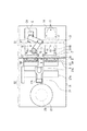
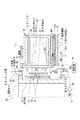
本発明に係る蓋体開閉装置が組み込まれた縦型熱処理装置について説明する。図1は縦型熱処理装置1の縦断側面図、図2は縦型熱処理装置1の平面図である。図中11は縦型熱処理装置1の外装体を構成する筐体であり、この筐体11内には、被処理体であるウエハWを収納した容器であるキャリアCが装置に対して搬入、搬出されるためのキャリア搬送領域S1と、キャリアC内のウエハWを搬送して後述の熱処理炉内に搬入するための移載領域であるウエハ搬送領域S2とが形成されている。キャリアCは既述のFOUPである。
(First embodiment)
A vertical heat treatment apparatus incorporating the lid opening / closing apparatus according to the present invention will be described. FIG. 1 is a vertical side view of the vertical
キャリア搬送領域S1とウエハ搬送領域S2とは隔壁2により仕切られている。キャリア搬送領域S1は大気雰囲気である。一方、ウエハ搬送領域S2は搬入されたウエハWに酸化膜が形成されることを防ぐために、不活性ガス雰囲気例えば窒素(N2)ガス雰囲気とされており、キャリアS1よりも清浄度が高く且つ低酸素濃度に維持されている。以降の装置の説明では、キャリア搬送領域S1及びウエハ搬送領域S2の配列方向を縦型熱処理装置1の前後方向とする。
The carrier transfer area S1 and the wafer transfer area S2 are partitioned by a
キャリア搬送領域S1について説明する。キャリア搬送領域S1は、第1の搬送領域12と、第1の搬送領域12の後方側(ウエハ搬送領域S2側)に位置する第2の搬送領域13とからなる。第1の搬送領域12の左右方向には、キャリアCを各々載置する2つの第1の載置台14が設けられている。各第1の載置台14の載置面には、キャリアCを位置決めするピン15が例えば3個所に設けられている。
The carrier transport area S1 will be described. The carrier transfer area S1 includes a
第2の搬送領域13には、第1の載置台14に対して前後に並ぶように、左右に2つの第2の載置台16が配置されている。各第2の載置台16は進退機構17により前後に移動自在に構成されており、後述のキャリアCからウエハWをウエハ搬送領域S2に受け渡すための受け渡し位置と、後述のキャリア搬送機構21からキャリアCを受け取る受け取り位置との間で当該キャリアCを搬送する。第2の載置台16の載置面にも第1の載置台14と同様にキャリアCを位置決めするピン15が、3個所に設けられている。また、前記載置面にはキャリアCを固定するためのフック16aが設けられている。第2の搬送領域13の上部側にはキャリアCを保管するキャリア保管部18が設けられている。キャリア保管部18は2段の棚により構成されており、各棚は左右に2つのキャリアCを載置することができる。
In the
そして、第2の搬送領域13には、キャリアCを第1の載置台14と第2の載置台16とキャリア保管部18との間で搬送するキャリア搬送機構21が設けられている。このキャリア搬送機構21は左右に伸び、且つ昇降自在なガイド部21aと、このガイド部21aにガイドされながら左右に移動する移動部21bと、この移動部21bに設けられ、キャリアCを保持して水平方向に搬送する関節アーム21cと、を備えている。
In the
第2の搬送領域13の天井部にはHEPAフィルタまたはULPAフィルタを備えたフィルタユニット31が設けられており、上記のフィルタを通過することにより清浄化されたエアを下方に向けて供給する。フィルタユニット31の下方にはイオナイザ32が設けられ、前記フィルタユニット31から供給されたエアをイオン化する。イオン化されたエアは、第2の載置台16へ向けて供給される。
A
図3はイオナイザ32の上面を示している。イオナイザ32は、例えばこのように横方向に複数配列された棒状の電極34により構成され、前記エアは電極34間を通過して下方へ供給される。電極34には電源35より交流電圧が印加される。交流電圧が印加された電極34の周囲に形成される電界にエアが接触することで、当該エアがイオン化され、プラスのエアのイオンとマイナスのエアのイオンとが発生する。このイオン化されたエアが帯電物に当たると同極性のイオンとは反発し、反対極性のイオンを吸引する結果、帯電物が除電されることになる。
FIG. 3 shows the top surface of the
隔壁2には、キャリア搬送領域S1とウエハ搬送領域S2とを連通させるウエハWの搬送口20が設けられている。搬送口20には、当該搬送口20をウエハ搬送領域S2側から塞ぐ開閉ドア5が設けられている。開閉ドア5には駆動機構50が接続されており、駆動機構50により開閉ドア5は前後方向及び上下方向に移動自在に構成され、搬送口20が開閉される。この開閉ドア5及び搬送口20の周囲の構成については後に詳述する。
The
ウエハ搬送領域S2には、下端が炉口として開口された縦型の熱処理炉22が設けられ、この熱処理炉22の下方側には、多数枚のウエハWを棚状に保持するウエハボート23が断熱部24を介してキャップ25の上に載置されている。キャップ25は昇降機構26の上に支持されており、この昇降機構26によりウエハボート23が熱処理炉22に対して搬入あるいは搬出される。
In the wafer transfer region S2, a vertical
またウエハボート23と隔壁2の搬送口20との間には、ウエハ搬送機構27が設けられている。このウエハ搬送機構27は、左右に伸びるガイド機構27aに沿って移動すると共に鉛直軸回りに回動する移動体27bに、5枚の進退自在なアーム27cを設けて構成され、ウエハボート23と第2の載置台16上のキャリアCとの間でウエハWを搬送する。
A
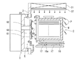
図4、図5は夫々キャリアC、ウエハWの搬送口20及び開閉ドア5の縦断側面図、横断平面図であり、図6は搬送口20及びキャリアCの斜視図である。これら図4〜図6を用いてキャリアCについて説明すると、キャリアCは容器本体であるキャリア本体41と、蓋体42とからなる。キャリア本体41内の左右には、ウエハWの裏面側周縁部を支持する支持部41aが多段に設けられる。キャリア本体41の前面にはウエハWの取り出し口43が形成されている。図中44は前記取り出し口43の開口縁部であり、開口縁部44の内周側の左右の上下には各々係合溝44aが形成されている。
4 and 5 are a longitudinal sectional side view and a transverse plan view of the carrier C, the
キャリア本体41の上部には、既述のキャリア搬送機構21がキャリアCを搬送するために把持する把持部41bが設けられる。また、図4に示すようにキャリア本体41の下部には凹部45aと溝部45bとが設けられ、凹部45aは第1の載置台14及び第2の載置台16のピン15に嵌合する。溝部45bは、第2の載置台16のフック16aに係合し、この係合によってキャリア本体41が第2の載置台16に固定される。
On the upper part of the carrier
キャリアCの蓋体42について説明すると、蓋体42の内部には左右に回動部46が設けられている。回動部46の上下には垂直方向に伸びる直動部47が設けられる。この直動部47は、回動部46の回動に応じて昇降し、その先端が蓋体42の側面から突出した状態と、蓋体42内に引き込んだ状態とで切り替わるように構成されている。図6は前記直動部47の先端が突出した状態を示している。この先端は前記キャリア本体41の係合溝44aに係合し、それによって蓋体42がキャリア本体41に係合される。蓋体42の前面には後述のキー69を蓋体42の内部に差し込むための開口部48が設けられている。
The
続いて、開閉ドア5及びウエハWの搬送口20の構成について説明する。搬送口20におけるキャリア搬送領域S1側の口縁部には、キャリア本体41の開口縁部44が当接する位置にシール部材51が設けられている。また、搬送口20における側縁部側には図5に示すようにN2ガス供給管52が垂直に設けられている。このN2ガス供給管52は上下にガス供給口53を備えている。このガス供給口53は、キャリアCがウエハ搬送領域S2との間でウエハWを受け渡すために、シール部材51に開口縁部44が密着する位置(受け渡し位置とする)に移動したときに、キャリアCと開閉ドア5とに囲まれて形成される閉塞空間にN2ガスを供給する。また搬送口20の下端部には、横長の排気口55が設けられている。図中55aは横方向における排気の偏りを抑えるために排気口55に設けられた多孔質体である。
Next, the configuration of the opening /
開閉ドア5は、その周縁部がキャリア搬送領域S1側へ向けて屈曲された箱体として形成されており、この箱体の開口縁にはシール部材56が設けられ、当該シール部材56を介して開閉ドア5は搬送口20の縁部に密着する。
The opening /
開閉ドア5のキャリア搬送領域S1側には、蓋体42の取り外し機構6が設けられている。この取り外し機構6は、対向板61と対向板61を前後方向に移動させる進退機構62とを備えている。対向板61は、第2の載置台16に載置された蓋体42の前面に対向する対向面部60を備えている。図6に示すように対向面部60には例えば横方向の中央の上下に夫々ガス吐出口63が開口している。ガス吐出口63には配管64の一端が接続され、配管64の他端はN2ガス供給機構65に接続されており、N2ガス供給機構65は下流側へパージガスであるN2ガスを圧送する。配管64にはイオナイザ66が介設されている。このイオナイザ66は既述のイオナイザ32と同様に電極を備え、当該電極の周囲に生じた電界に曝され、イオン化されたN2ガスが前記ガス吐出口63から吐出される。図4中dは、対向面部60と蓋体42の前面との距離である。後述のようにキャリアCが取り外し機構6に近づき、この距離dが5mm以下になるとガス吐出口63からN2ガスが吐出される。
A
対向面部60には、ガス吐出口63から当該ガス吐出口63の外側へと旋回しながら伸びる旋回溝67が設けられている。例えば旋回溝67は、各ガス吐出口63の周方向に4本形成され、夫々左向きに旋回するように形成されている。図7はガス吐出口63及び旋回溝67の正面図である。キャリアCの蓋体42と対向面部60とが対向した状態でガス吐出口63からN2ガスを吐出するときに、図7に矢印で示すように、当該N2ガスが旋回溝67によりガイドされる。それによって、ガス吐出口63を中心とするN2ガスの旋回流が生じる。なお、ガス吐出口63の配置や個数はこの例に限られるものではなく、例えば対向面部60の中央に一つ設けてもよい。また、旋回溝67は右向きに旋回するように形成してもよい。
The opposing
図4〜図6に戻って、対向面部60からその厚さ方向に棒状の接続部68が伸びており、接続部68の先端には円い棒状のキー(ラッチピン)69が設けられている。接続部68はその軸回りに回動し、それによってキー69も回動する。キー69は上記の蓋体42の回動部46に係合し、当該回動部46を回動させることができるように形成されている。キー69の形状としてはこの係合が行えるものであればよいので図示した円柱形状には限られず、例えば角柱形状であったり、これら円柱または角柱の角部を丸く形成したものであってもよい。
Returning to FIGS. 4 to 6, a rod-
この縦型熱処理装置1には、例えばコンピュータからなる制御部1Aが設けられている。制御部1Aはプログラム、メモリ、CPUからなるデータ処理部などを備えており、前記プログラムには制御部1Aから縦型熱処理装置1の各部に制御信号を送り、後述の各処理工程を進行させるように命令(各ステップ)が組み込まれている。その制御信号によりキャリアCの搬送、第2の載置台16の進退、取り外し機構6の進退、ウエハWの搬送、蓋体42の開閉、開閉ドア5の開閉、蓋体42へのN2ガスの供給などの動作が制御され、後述のようにウエハWの搬送及び処理が行われる。このプログラムは、コンピュータ記憶媒体例えばフレキシブルディスク、コンパクトディスク、ハードディスク、MO(光磁気ディスク)及びメモリーカードなどの記憶媒体に格納されて制御部1Aにインストールされる。
The vertical
次に上述の実施の形態の作用について説明する。フィルタユニット31から下方へ向けてエアが供給され、このエアがイオナイザ32によりイオン化されて、さらに下方へ供給され、第2の載置台16が設けられる第2の搬送領域13に下降気流が形成される。この下降気流により、前記第2の搬送領域13に存在するパーティクルは除電され、キャリアCへの付着力が弱まる。
Next, the operation of the above embodiment will be described. Air is supplied downward from the
そして、クリーンルームの天井部に沿って移動する図示しない自動搬送ロボットにより、キャリアCが第1の載置台14に載置される。続いてキャリア搬送機構21により前記キャリアCが第2の載置台16に搬送され、フック16aにより第2の載置台16に固定される。
Then, the carrier C is mounted on the first mounting table 14 by an automatic transfer robot (not shown) that moves along the ceiling of the clean room. Subsequently, the carrier C is transported to the second mounting table 16 by the
進退機構17により、第2の載置台16は隔壁2の搬送口20へ向けて前進し、キャリアCは前記下降気流に曝されながら移動する。キャリアCに付着しているパーティクルPは、前記下降気流により除電され、当該パーティクルPのキャリアCに対する付着力が弱まり、当該気流に押し流されてキャリアCから除去される(図8)。対向面部60とキャリアCの蓋体42との距離dが5mmになると、第2の載置台16の移動速度が低下すると共に当該ガス吐出口63から蓋体42へイオナイザ65によりイオン化されたN2ガスが吐出される。ガス吐出口63から吐出されたN2ガスは、蓋体42の前面と取り外し機構6の対向面部60との隙間を流れ、蓋体42の前面に付着しているパーティクルPを除電し、このパーティクルPの蓋体42への付着力が弱まる。そして、付着力が弱まったパーティクルPはこのN2ガスにより蓋体42から押し流されて除去される(図9)。
By the advance /
キャリアCの前進が続けられ、取り外し機構6のキー69が蓋体42の開口部48を介して蓋体42内に進入し、上記の距離dが所定の大きさになると、ガス吐出口63からN2ガスの吐出が停止する。さらにキャリアCが前進し、ウエハを受け渡すための受け渡し位置に移動し、隔壁2の搬送口20の周りのシール部材51にキャリアCの開口縁部44が当接して、キャリアCと開閉ドア5との間に閉塞空間54が形成されると共に、前記取り外し機構6のキー69が蓋体42内の回動部46に係合する(図10)。
When the carrier C continues to advance, the key 69 of the
前記閉塞空間54の大気雰囲気が排気口55から排気されると共に、ガス供給口53からN2ガスが当該閉塞空間54に供給され、当該閉塞空間54にN2ガス雰囲気が形成される。キー69が90度回動し、蓋体42とキャリア本体41との係合が解除されると共にキー69に蓋体42が保持され、キー69が蓋体42を保持した状態で対向板61が開閉ドア5へ向けて後退して、キャリア本体41のウエハWの取り出し口43が開放される(図11)。
The atmospheric atmosphere in the enclosed
開閉ドア5が後退した後、下降して搬送口20から退避し、キャリアC内がウエハ搬送領域S2に開放され(図12)、ウエハ搬送機構27によりキャリアC内のウエハWが順次取り出されてウエハボート23に移載される。キャリアC内のウエハWが空になると、上述と逆の動作でキャリアCの蓋体42が閉じられると共にキャリア本体41に固定される。然る後、第2の載置台16が後退してキャリアCが隔壁2から離れ、キャリア搬送機構21によりキャリア保管部18に搬送されて一時的に保管される。一方、ウエハWが搭載されたウエハボート23は熱処理炉22内に搬入されて、ウエハWに熱処理例えばCVD、アニール処理、酸化処理などが行われる。その後、処理を終えたウエハWをキャリアCに戻すときも、キャリアCからウエハWを払い出すときと同様の手順で蓋体42が開放される。
After the open /
この縦型熱処理装置1は、隔壁の搬送口20を開閉する開閉ドア5に設けられ、キャリアCの蓋体42の前面に対向する対向板61と、当該対向板61の対向面部60に設けられたガス吐出口63と、を備え、前記対向面部60と前記蓋体42との距離dを5mmにして、ガス吐出口63からN2ガスを吐出している。このように距離dを調整することで、後述の実験にも示すように前記N2ガスの流速を大きくし、蓋体42に付着したパーティクルを確実に除去することができる。従って、パーティクルが蓋体42を介してキャリア搬送領域S1からウエハ搬送領域S2に混入することを抑えることができる。後述の実験より前記距離dは5mmに限られず、5mm以下であればよい。
The vertical
前記N2ガスはイオナイザ65によりイオン化されているため、より確実に蓋体42のパーティクルを除去できる。また、前記対向面部60に設けられた旋回溝67により、対向板61の厚さ方向に見て、旋回するようにN2ガスの流れが形成される。このような流れを形成することでパーティクルに作用する風圧が大きくなるので、蓋体42のパーティクルの除去率を高くすることができる。さらに、イオン化されたN2ガスによる下降気流をキャリアCに供給しているため、キャリアCのパーティクルの付着を抑えると共にキャリアCからのパーティクルの除去率が高くなるため、より確実にウエハ搬送領域S2へのパーティクルの混入を抑えることができる。
Since the N2 gas is ionized by the
また、ガス吐出口63からN2ガスを吐出する位置に至るまでは第2の載置台16の移動速度を大きくし、前記位置からさらにキャリアCを前進させるときには、当該第2の載置台16の移動速度を低下させている。これによって十分な時間、蓋体42がN2ガスに曝されてパーティクルが蓋体に残留することを防ぎ、且つキャリアCが前記閉塞空間54を形成するウエハの受け渡し位置に移動するまでの時間を抑え、スループットの低下を抑えることができる。また、上記の実施形態では、ガス吐出口63からガスを吐出するときに第2の載置台16の速度が低下させているが、速度を低下させる代わりに一旦第2の載置台16の前進を停止させてもよい。つまり、第2の載置台16の前進を止めた状態で、前記N2ガスの供給を続け、N2ガスの供給停止後に再度第2の載置台16を前進させてもよい。
Further, the moving speed of the second mounting table 16 is increased until reaching the position where the N2 gas is discharged from the
上記の例ではキャリアCを前進させるときにガス吐出口63からN2ガスの吐出を行っているが、対向板61を前進させるときにN2ガスの吐出を行ってもよい。例えば図13に示すように、先ずキャリアCを前記受け渡し位置に移動させる。そして、対向板61をキャリアCに向けて前進させ、上記のように距離dが5mm以下になったときにN2ガスを吐出する。蓋体42から除去されたパーティクルPは、排気口55から排気されて除去される。この場合にも上記の例と同様にN2ガスの供給開始前は対向板61の前進速度を大きくし、N2ガスの供給開始後は対向板61の前進速度を小さくすることで、スループットの向上とパーティクルの除去率の上昇とを図ることができる。また、この場合にも前進速度を小さくする代わりに、一旦対向板61の前進を止めてガス供給を行ってもよい。
In the above example, N2 gas is discharged from the
被処理体が半導体ウエハである例について説明したが、被処理体はこれに限られずガラス基板やLCD基板であってもよい。また、開閉ドア5及び隔壁2は大気雰囲気と不活性ガス雰囲気とを区画することに限られず、例えば互いに湿度が異なるように制御された領域を区画する構成であってもよい。また、ガス吐出口63から吐出するパージガスはN2ガスに限られず、エアやArなど他の不活性ガスであってもよい。
Although an example in which the object to be processed is a semiconductor wafer has been described, the object to be processed is not limited to this and may be a glass substrate or an LCD substrate. In addition, the opening /
(評価試験1)
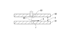
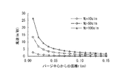
本発明に関連する評価試験1について説明する。図14、15に示すように2つの板81、82を対向させた。板82の中心にはN2ガスの吐出口83が形成され、ガス供給管84から供給されたN2ガスを板の厚さ方向に供給できるようになっている。図中Xは板81、82の隙間を示している。板81の表面に測定ポイントAを設定し、当該測定ポイントAの風速について、前記隙間Xの大きさ及び吐出口83からのN2ガス流量を夫々変更して測定した。図中rは、吐出口83の中心軸85から前記測定ポイントAの距離を示し、この評価試験1ではr=150mmに設定した。N2ガスの流量は、10slm(L/分)、50slm、100slmに夫々設定した。
(Evaluation Test 1)
The
図16のグラフに実験結果を示している。グラフ中の縦軸は測定ポイントAの風速(単位:m/秒)を示し、横軸は前記隙間Xの大きさ(単位:mm)を示している。N2ガスの流量が10slm、50slm、100slmのいずれの場合であっても隙間Xが大きくなるにつれて風速が低下していき、Xが5mmでは0に近くなる。5mmを越えると風速は略0になると考えられ、上記の実施形態に適用した場合にパーティクルの除去能力が低くなってしまうと考えられることから、上記の実施形態で説明したように、蓋体42と対向面部60との距離を5mm以下に近接させることが必要であることが分かる。また、この評価試験1でN2ガスの流量がいずれの場合であっても、Xが1mm以下になると、風速の上昇率が高くなる。従って、上記の実施形態で、距離dが1mm以下であるときにガス吐出口63からN2ガスを吐出することが特に有効である。
The experimental results are shown in the graph of FIG. The vertical axis in the graph indicates the wind speed (unit: m / second) at the measurement point A, and the horizontal axis indicates the size of the gap X (unit: mm). Even if the flow rate of N2 gas is any of 10 slm, 50 slm, and 100 slm, the wind speed decreases as the gap X increases, and near 0 when X is 5 mm. If it exceeds 5 mm, the wind speed is considered to be substantially zero, and when applied to the above-described embodiment, it is considered that the ability to remove particles becomes low. Therefore, as described in the above-described embodiment, the
なお、クリーンルームに持ち込まれる資材などにエアを吐出し、パーティクルを除去するエアシャワーは、前記エアの風速が20〜30m/秒となるように設計されている。この実験で測定した範囲ではN2ガスの流量を100slmに設定し、前記Xが0mmに近づいたときに風速が20m/秒となっている。従って、このエアシャワーと同等の性能を得るためには、上記の実施形態でガス吐出口63から吐出するN2ガスを100slm以上の流量に設定することが有効である。
In addition, the air shower which discharges air to the material etc. which are brought into a clean room, and removes a particle is designed so that the wind speed of the said air may be 20-30 m / sec. In the range measured in this experiment, the flow rate of N2 gas is set to 100 slm, and when the X approaches 0 mm, the wind speed is 20 m / sec. Therefore, in order to obtain the same performance as this air shower, it is effective to set the N2 gas discharged from the
(評価試験2)
評価試験1と同様の装置を用い、前記測定ポイントAの位置、つまり前記rの大きさを変えて風速の測定を行った。前記隙間Xの大きさは1mmに設定した。N2ガスの流量は、評価試験1と同様に10slm、50slm、100slmに夫々設定した。
(Evaluation test 2)
Using the same apparatus as in
図17は、この実験の結果を示すグラフである。グラフ中の縦軸は測定ポイントAの風速(単位m/秒)を示し、横軸は前記rの大きさ(単位mm)を示している。グラフに示すようにrが小さいほど、各流量間で風速の差が大きい。そして、rが大きくなるほど各流量間で風速の差が小さくなり、次第に0に近づいていく。従って、対向板61において、確実にパーティクルを除去するために当該対向板61のガス吐出口63は複数設けることが好ましい。
FIG. 17 is a graph showing the results of this experiment. The vertical axis in the graph indicates the wind speed (unit m / second) at the measurement point A, and the horizontal axis indicates the size of r (unit mm). As shown in the graph, the smaller r is, the greater the difference in wind speed between the flow rates. As r increases, the difference in wind speed between the flow rates decreases, and gradually approaches zero. Therefore, it is preferable to provide a plurality of
C キャリア
W ウエハ
S1 キャリア搬送領域
S2 ウエハ搬送領域
1 縦型熱処理装置
1A 制御部
16 第2の載置台
17 進退機構
2 隔壁
20 搬送口
31 フィルタユニット
32 イオナイザ
5 開閉ドア
6 取り外し機構
61 対向板
60 対向面部
63 ガス吐出口
66 イオナイザ
C Carrier W Wafer S1 Carrier transfer area S2
図17は、この実験の結果を示すグラフである。グラフ中の縦軸は測定ポイントAの風速(単位m/秒)を示し、横軸は前記rの大きさ(単位m)を示している。グラフに示すようにrが小さいほど、各流量間で風速の差が大きい。そして、rが大きくなるほど各流量間で風速の差が小さくなり、次第に0に近づいていく。従って、対向板61において、確実にパーティクルを除去するために当該対向板61のガス吐出口63は複数設けることが好ましい。
FIG. 17 is a graph showing the results of this experiment. The vertical axis in the graph represents the wind speed (unit m / second) at the measurement point A, and the horizontal axis represents the magnitude of r (unit m 2 ). As shown in the graph, the smaller r is, the greater the difference in wind speed between the flow rates. As r increases, the difference in wind speed between the flow rates decreases, and gradually approaches zero. Therefore, it is preferable to provide a plurality of
Claims (7)
前記蓋体の前面が前記搬送口に向くようにFOUPを載置する載置台と、
前記対向面部に設けられ、前記蓋体に付着したパーティクルを除去するためのパージガスを供給するためのガス吐出口と、
前記載置台に載置されたFOUPを、前記対向面部に対して相対的に進退させる進退機構と、
前記対向面部から前記FOUPの蓋体までの距離が5mm以下であり、且つ蓋体と対向面部とが離間しているガス供給有効位置にFOUPが置かれている状態で前記ガス吐出口から前記蓋体へパージガスを供給し、その後蓋体をFOUPから取り外すように制御信号を出力する制御部と、
を備えたことを特徴とする蓋体開閉装置。 Formed in a partition wall that divides the atmosphere of the FOUP transfer area and the atmosphere of the substrate transfer area, the opening edge of the FOUP substrate take-out opening is brought into close contact with the opening edge of the transfer opening that is opened and closed by the open / close door. The lid removing mechanism provided on the surface of the door facing the FOUP is made to enter the lid through the opening on the front side of the lid of the FOUP to release the engagement between the lid and the FOUP body. In the FOUP opening and closing device configured to hold the lid,
A mounting table on which the FOUP is mounted so that the front surface of the lid faces the transport port;
A gas discharge port for supplying a purge gas provided on the facing surface portion for removing particles attached to the lid;
An advancing / retreating mechanism for advancing and retracting the FOUP placed on the mounting table relative to the facing surface part;
The distance from the opposed surface portion to the lid of the FOUP is 5 mm or less, and the lid from the gas discharge port in the state where the FOUP is placed at a gas supply effective position where the lid and the opposed surface portion are separated from each other. A control unit that supplies a purge gas to the body and then outputs a control signal to remove the lid from the FOUP;
A lid opening and closing device comprising:
パージガスの供給を続けたまま、当該FOUPを前記ガス供給有効位置で停止させるか、あるいは第1の速度よりも遅い第2の速度で、前記ガス供給有効位置よりも前記対向面部に接近させるように制御信号を出力することを特徴とする請求項1記載の蓋体開閉装置。 The control unit advances the FOUP at the first speed to the gas supply effective position,
While continuing the supply of the purge gas, the FOUP is stopped at the gas supply effective position, or at a second speed slower than the first speed, the FOUP is moved closer to the opposed surface portion than the gas supply effective position. 2. The lid opening / closing device according to claim 1, wherein a control signal is output.
前記蓋体の前面が前記搬送口に向くようにFOUPを載置する載置台と、
前記対向面部に設けられ、前記蓋体に付着したパーティクルを除去するためのパージガスを供給するためのガス吐出口と、
前記載置台に載置されたFOUPを、前記対向面部に対して相対的に進退させる進退機構と、
前記ガス吐出口から吐出されるパージガスをイオン化させるための第1のイオナイザと、
を備えることを特徴とする蓋体開閉装置。 Formed in a partition wall that divides the atmosphere of the FOUP transfer area and the atmosphere of the substrate transfer area, the opening edge of the FOUP substrate take-out opening is brought into close contact with the opening edge of the transfer opening that is opened and closed by the open / close door. The lid removing mechanism provided on the surface of the door facing the FOUP is made to enter the lid through the opening on the front side of the lid of the FOUP to release the engagement between the lid and the FOUP body. In the FOUP opening and closing device configured to hold the lid,
A mounting table on which the FOUP is mounted so that the front surface of the lid faces the transport port;
A gas discharge port for supplying a purge gas provided on the facing surface portion for removing particles attached to the lid;
An advancing / retreating mechanism for advancing and retracting the FOUP placed on the mounting table relative to the facing surface part;
A first ionizer for ionizing a purge gas discharged from the gas discharge port;
A lid opening / closing device comprising:
前記フィルタユニットから供給される大気をイオン化させる第2のイオナイザと、を備えたことを特徴とする請求項1ないし6のいずれか一つに記載の蓋体開閉装置。 A filter unit that is provided above the mounting table and includes a filter, and supplies the air that has passed through the filter and purified downward to form a downward airflow;
The lid opening / closing device according to any one of claims 1 to 6, further comprising a second ionizer that ionizes the atmosphere supplied from the filter unit.
Priority Applications (5)
| Application Number | Priority Date | Filing Date | Title |
|---|---|---|---|
| JP2011068399A JP2012204645A (en) | 2011-03-25 | 2011-03-25 | Lid opening/closing device |
| TW101109108A TWI533386B (en) | 2011-03-25 | 2012-03-16 | Lid opening and closing device |
| US13/426,006 US9082807B2 (en) | 2011-03-25 | 2012-03-21 | Lid opening and closing device |
| CN201210077097.7A CN102693926B (en) | 2011-03-25 | 2012-03-21 | cover body opening/closing apparatus |
| KR20120030169A KR20120109413A (en) | 2011-03-25 | 2012-03-23 | Lid opening and closing device |
Applications Claiming Priority (1)
| Application Number | Priority Date | Filing Date | Title |
|---|---|---|---|
| JP2011068399A JP2012204645A (en) | 2011-03-25 | 2011-03-25 | Lid opening/closing device |
Related Child Applications (1)
| Application Number | Title | Priority Date | Filing Date |
|---|---|---|---|
| JP2014144393A Division JP5807708B2 (en) | 2014-07-14 | 2014-07-14 | Lid opening / closing device |
Publications (1)
| Publication Number | Publication Date |
|---|---|
| JP2012204645A true JP2012204645A (en) | 2012-10-22 |
Family
ID=46859288
Family Applications (1)
| Application Number | Title | Priority Date | Filing Date |
|---|---|---|---|
| JP2011068399A Pending JP2012204645A (en) | 2011-03-25 | 2011-03-25 | Lid opening/closing device |
Country Status (5)
| Country | Link |
|---|---|
| US (1) | US9082807B2 (en) |
| JP (1) | JP2012204645A (en) |
| KR (1) | KR20120109413A (en) |
| CN (1) | CN102693926B (en) |
| TW (1) | TWI533386B (en) |
Cited By (6)
| Publication number | Priority date | Publication date | Assignee | Title |
|---|---|---|---|---|
| JP2014112631A (en) * | 2012-10-31 | 2014-06-19 | Tdk Corp | Load port unit and EFEM system |
| KR20160113013A (en) | 2015-03-20 | 2016-09-28 | 도쿄엘렉트론가부시키가이샤 | Clamp apparatus, substrate carry-in/out apparatus using the same, and substrate processing apparatus |
| KR20190067106A (en) | 2017-12-06 | 2019-06-14 | 도쿄엘렉트론가부시키가이샤 | Substrate carrying in and out apparatus, substrate processing apparatus and antistatic method of substrate conveying container |
| JP2020510320A (en) * | 2017-03-14 | 2020-04-02 | アプライド マテリアルズ インコーポレイテッドApplied Materials,Incorporated | Load port operation in electronic device manufacturing apparatus, system, and method |
| JP2021090072A (en) * | 2015-08-04 | 2021-06-10 | シンフォニアテクノロジー株式会社 | Load port with door opening and closing system and door opening and closing system |
| JP2021521656A (en) * | 2018-05-11 | 2021-08-26 | ベイジン・ナウラ・マイクロエレクトロニクス・イクイップメント・カンパニー・リミテッドBeijing NAURA Microelectronics Equipment Co.,LTD | Door openers, transport chambers, and semiconductor processing devices |
Families Citing this family (24)
| Publication number | Priority date | Publication date | Assignee | Title |
|---|---|---|---|---|
| JP5617708B2 (en) * | 2011-03-16 | 2014-11-05 | 東京エレクトロン株式会社 | Lid opening / closing device |
| CN102889791B (en) * | 2012-09-27 | 2014-11-19 | 北京七星华创电子股份有限公司 | Furnace exhaust control device |
| CN103625926B (en) * | 2013-01-16 | 2015-12-02 | 世源科技工程有限公司 | Self-cleaning method for carrying |
| JP6198043B2 (en) * | 2013-06-06 | 2017-09-20 | Tdk株式会社 | Load port unit and EFEM system |
| WO2015023591A1 (en) | 2013-08-12 | 2015-02-19 | Applied Materials, Inc | Substrate processing systems, apparatus, and methods with factory interface environmental controls |
| CN103600875B (en) * | 2013-11-15 | 2015-08-19 | 嘉兴景焱智能装备技术有限公司 | Take off and cover lid arrangement |
| JP6263407B2 (en) * | 2014-02-10 | 2018-01-17 | 光洋サーモシステム株式会社 | Heat treatment equipment |
| US20150311100A1 (en) * | 2014-04-23 | 2015-10-29 | Tdk Corporation | Load port unit and efem system |
| WO2016085622A1 (en) | 2014-11-25 | 2016-06-02 | Applied Materials, Inc. | Substrate processing systems, apparatus, and methods with substrate carrier and purge chamber environmental controls |
| JP6451453B2 (en) * | 2015-03-31 | 2019-01-16 | Tdk株式会社 | GAS PURGE DEVICE, LOAD PORT DEVICE, PURGE CONTAINER CONTAINER STAND, AND GAS PURGE METHOD |
| JP6554872B2 (en) * | 2015-03-31 | 2019-08-07 | Tdk株式会社 | GAS PURGE DEVICE, LOAD PORT DEVICE, PURGE CONTAINER CONTAINER STAND, AND GAS PURGE METHOD |
| CN107851597B (en) * | 2015-08-04 | 2021-10-01 | 株式会社国际电气 | Substrate processing apparatus, method of manufacturing semiconductor device, and recording medium |
| TWI727562B (en) * | 2015-08-04 | 2021-05-11 | 日商昕芙旎雅股份有限公司 | Load port |
| JP6561700B2 (en) * | 2015-09-04 | 2019-08-21 | シンフォニアテクノロジー株式会社 | Gas injection equipment |
| JP6632403B2 (en) * | 2016-02-02 | 2020-01-22 | 東京エレクトロン株式会社 | Connection mechanism and connection method for substrate storage container |
| JP6675948B2 (en) * | 2016-08-03 | 2020-04-08 | 東京エレクトロン株式会社 | Lid and substrate processing apparatus using the same |
| US10741432B2 (en) * | 2017-02-06 | 2020-08-11 | Applied Materials, Inc. | Systems, apparatus, and methods for a load port door opener |
| US10388547B2 (en) | 2017-06-23 | 2019-08-20 | Applied Materials, Inc. | Side storage pods, equipment front end modules, and methods for processing substrates |
| TWI676089B (en) | 2017-06-23 | 2019-11-01 | 美商應用材料股份有限公司 | Side storage pod, electronic device processing systems, and methods of processing substrates |
| US10763134B2 (en) | 2018-02-27 | 2020-09-01 | Applied Materials, Inc. | Substrate processing apparatus and methods with factory interface chamber filter purge |
| TWI742826B (en) * | 2020-08-28 | 2021-10-11 | 樂華科技股份有限公司 | Wafer carrier vacuum moving device and method |
| US11302552B1 (en) * | 2021-01-07 | 2022-04-12 | Taiwan Semiconductor Manufacturing Company, Ltd. | Multiple transport carrier docking device |
| US11302553B1 (en) * | 2021-01-07 | 2022-04-12 | Taiwan Semiconductor Manufacturing Company, Ltd. | Transport carrier docking device |
| CN114420616A (en) * | 2022-03-28 | 2022-04-29 | 西安奕斯伟材料科技有限公司 | Groove type cleaning device |
Citations (11)
| Publication number | Priority date | Publication date | Assignee | Title |
|---|---|---|---|---|
| JPH09320914A (en) * | 1996-05-30 | 1997-12-12 | Tokyo Electron Ltd | Treatment system |
| JP2002118161A (en) * | 2000-10-12 | 2002-04-19 | Hitachi Ltd | Method for fabricating semiconductor integrated circuit device |
| JP2002368061A (en) * | 2001-06-12 | 2002-12-20 | Sony Corp | Device for opening/closing storage container and storage container |
| US20040168742A1 (en) * | 2003-02-12 | 2004-09-02 | Kim Hyun-Joon | Module for transferring a substrate |
| JP2005187967A (en) * | 2003-12-25 | 2005-07-14 | Paper Documents Conservation Studio Inc | Preservation and restoration method and apparatus for paper data |
| JP2007294938A (en) * | 2006-03-31 | 2007-11-08 | Hitachi Chem Co Ltd | Method and device for cleaning workpiece, and method and device for manufacturing printed wiring board |
| JP2008104929A (en) * | 2006-10-24 | 2008-05-08 | Ikeuchi:Kk | Nozzle |
| JP2009018250A (en) * | 2007-07-11 | 2009-01-29 | East Japan Railway Co | Cleaning method, cleaning device, and cleaning nozzle |
| US20090169342A1 (en) * | 2004-06-21 | 2009-07-02 | Takehiko Yoshimura | Load port |
| JP2010056296A (en) * | 2008-08-28 | 2010-03-11 | Tdk Corp | System and method for opening/closing lid of sealed vessel |
| JP2010165741A (en) * | 2009-01-13 | 2010-07-29 | Hitachi High-Tech Control Systems Corp | Mini-environment substrate transport device, load port and method of eliminating electricity in substrate within transport container |
Family Cites Families (22)
| Publication number | Priority date | Publication date | Assignee | Title |
|---|---|---|---|---|
| US4687542A (en) * | 1985-10-24 | 1987-08-18 | Texas Instruments Incorporated | Vacuum processing system |
| US5169272A (en) * | 1990-11-01 | 1992-12-08 | Asyst Technologies, Inc. | Method and apparatus for transferring articles between two controlled environments |
| DE4035312A1 (en) * | 1990-11-07 | 1992-05-14 | Bosch Gmbh Robert | DEVICE FOR INJECTING A FUEL-GAS MIXTURE |
| JP3796782B2 (en) * | 1995-11-13 | 2006-07-12 | アシスト シンコー株式会社 | Mechanical interface device |
| TW333658B (en) * | 1996-05-30 | 1998-06-11 | Tokyo Electron Co Ltd | The substrate processing method and substrate processing system |
| JPH11214479A (en) * | 1998-01-23 | 1999-08-06 | Tokyo Electron Ltd | Apparatus and method of treating substrate and apparatus for transporting substrate |
| US6261044B1 (en) * | 1998-08-06 | 2001-07-17 | Asyst Technologies, Inc. | Pod to port door retention and evacuation system |
| JP2002118131A (en) * | 2000-10-05 | 2002-04-19 | Mitsubishi Plastics Ind Ltd | Solder ball |
| JP2002184831A (en) * | 2000-12-11 | 2002-06-28 | Hirata Corp | Foup opener |
| JP3369165B1 (en) * | 2002-04-09 | 2003-01-20 | 東京エレクトロン株式会社 | Vertical heat treatment equipment |
| WO2006030849A1 (en) * | 2004-09-15 | 2006-03-23 | Hitachi Kokusai Electric Inc. | Semiconductor manufacturing equipment and semiconductor device manufacturing method |
| JP4012190B2 (en) * | 2004-10-26 | 2007-11-21 | Tdk株式会社 | Closed container lid opening and closing system and opening and closing method |
| US20080107507A1 (en) * | 2005-11-07 | 2008-05-08 | Bufano Michael L | Reduced capacity carrier, transport, load port, buffer system |
| US7896602B2 (en) * | 2006-06-09 | 2011-03-01 | Lutz Rebstock | Workpiece stocker with circular configuration |
| JP4994724B2 (en) * | 2006-07-07 | 2012-08-08 | 株式会社東芝 | Film forming apparatus and film forming method |
| US7860379B2 (en) * | 2007-01-15 | 2010-12-28 | Applied Materials, Inc. | Temperature measurement and control of wafer support in thermal processing chamber |
| WO2009008047A1 (en) * | 2007-07-09 | 2009-01-15 | Kondoh Industries, Ltd. | Device for charging dry air or nitrogen gas into semiconductor wafer storage container and wafer static charge removing apparatus utilizing the device |
| JP4309935B2 (en) * | 2007-07-31 | 2009-08-05 | Tdk株式会社 | Closed container lid opening / closing system and substrate processing method using the system |
| JP4343253B1 (en) * | 2008-03-27 | 2009-10-14 | Tdk株式会社 | Lid opening / closing device for closed container and gas replacement device using the opening / closing device |
| JP5338335B2 (en) * | 2008-08-13 | 2013-11-13 | 東京エレクトロン株式会社 | Opening / closing device and probe device of transfer container |
| JP5273245B2 (en) * | 2009-05-12 | 2013-08-28 | 村田機械株式会社 | Purge apparatus and purge method |
| JP5617708B2 (en) * | 2011-03-16 | 2014-11-05 | 東京エレクトロン株式会社 | Lid opening / closing device |
-
2011
- 2011-03-25 JP JP2011068399A patent/JP2012204645A/en active Pending
-
2012
- 2012-03-16 TW TW101109108A patent/TWI533386B/en not_active IP Right Cessation
- 2012-03-21 US US13/426,006 patent/US9082807B2/en not_active Expired - Fee Related
- 2012-03-21 CN CN201210077097.7A patent/CN102693926B/en not_active Expired - Fee Related
- 2012-03-23 KR KR20120030169A patent/KR20120109413A/en not_active Application Discontinuation
Patent Citations (11)
| Publication number | Priority date | Publication date | Assignee | Title |
|---|---|---|---|---|
| JPH09320914A (en) * | 1996-05-30 | 1997-12-12 | Tokyo Electron Ltd | Treatment system |
| JP2002118161A (en) * | 2000-10-12 | 2002-04-19 | Hitachi Ltd | Method for fabricating semiconductor integrated circuit device |
| JP2002368061A (en) * | 2001-06-12 | 2002-12-20 | Sony Corp | Device for opening/closing storage container and storage container |
| US20040168742A1 (en) * | 2003-02-12 | 2004-09-02 | Kim Hyun-Joon | Module for transferring a substrate |
| JP2005187967A (en) * | 2003-12-25 | 2005-07-14 | Paper Documents Conservation Studio Inc | Preservation and restoration method and apparatus for paper data |
| US20090169342A1 (en) * | 2004-06-21 | 2009-07-02 | Takehiko Yoshimura | Load port |
| JP2007294938A (en) * | 2006-03-31 | 2007-11-08 | Hitachi Chem Co Ltd | Method and device for cleaning workpiece, and method and device for manufacturing printed wiring board |
| JP2008104929A (en) * | 2006-10-24 | 2008-05-08 | Ikeuchi:Kk | Nozzle |
| JP2009018250A (en) * | 2007-07-11 | 2009-01-29 | East Japan Railway Co | Cleaning method, cleaning device, and cleaning nozzle |
| JP2010056296A (en) * | 2008-08-28 | 2010-03-11 | Tdk Corp | System and method for opening/closing lid of sealed vessel |
| JP2010165741A (en) * | 2009-01-13 | 2010-07-29 | Hitachi High-Tech Control Systems Corp | Mini-environment substrate transport device, load port and method of eliminating electricity in substrate within transport container |
Cited By (14)
| Publication number | Priority date | Publication date | Assignee | Title |
|---|---|---|---|---|
| JP2014112631A (en) * | 2012-10-31 | 2014-06-19 | Tdk Corp | Load port unit and EFEM system |
| KR20160113013A (en) | 2015-03-20 | 2016-09-28 | 도쿄엘렉트론가부시키가이샤 | Clamp apparatus, substrate carry-in/out apparatus using the same, and substrate processing apparatus |
| US9857124B2 (en) | 2015-03-20 | 2018-01-02 | Tokyo Electron Limited | Clamp apparatus, substrate carry-in/out apparatus using the same, and substrate processing apparatus |
| JP2021090072A (en) * | 2015-08-04 | 2021-06-10 | シンフォニアテクノロジー株式会社 | Load port with door opening and closing system and door opening and closing system |
| JP7164824B2 (en) | 2015-08-04 | 2022-11-02 | シンフォニアテクノロジー株式会社 | Loadport with door opening system and door opening system |
| JP2022058408A (en) * | 2017-03-14 | 2022-04-12 | アプライド マテリアルズ インコーポレイテッド | Load port operation in electronic device manufacturing device, system, and method |
| US11081379B2 (en) | 2017-03-14 | 2021-08-03 | Applied Materials, Inc. | Load port operation in electronic device manufacturing apparatus, systems, and methods |
| JP7000447B2 (en) | 2017-03-14 | 2022-01-19 | アプライド マテリアルズ インコーポレイテッド | Load port operation in electronic device manufacturing equipment, systems, and methods |
| JP2020510320A (en) * | 2017-03-14 | 2020-04-02 | アプライド マテリアルズ インコーポレイテッドApplied Materials,Incorporated | Load port operation in electronic device manufacturing apparatus, system, and method |
| US11637029B2 (en) | 2017-03-14 | 2023-04-25 | Applied Materials, Inc. | Load port operation in electronic device manufacturing apparatus, systems, and methods |
| JP7441208B2 (en) | 2017-03-14 | 2024-02-29 | アプライド マテリアルズ インコーポレイテッド | Load port operation in electronic device manufacturing equipment, systems, and methods |
| KR20190067106A (en) | 2017-12-06 | 2019-06-14 | 도쿄엘렉트론가부시키가이샤 | Substrate carrying in and out apparatus, substrate processing apparatus and antistatic method of substrate conveying container |
| JP2021521656A (en) * | 2018-05-11 | 2021-08-26 | ベイジン・ナウラ・マイクロエレクトロニクス・イクイップメント・カンパニー・リミテッドBeijing NAURA Microelectronics Equipment Co.,LTD | Door openers, transport chambers, and semiconductor processing devices |
| JP7223123B2 (en) | 2018-05-11 | 2023-02-15 | ベイジン・ナウラ・マイクロエレクトロニクス・イクイップメント・カンパニー・リミテッド | Door openers, transport chambers, and semiconductor processing devices |
Also Published As
| Publication number | Publication date |
|---|---|
| TWI533386B (en) | 2016-05-11 |
| CN102693926B (en) | 2015-12-09 |
| US20120241032A1 (en) | 2012-09-27 |
| KR20120109413A (en) | 2012-10-08 |
| CN102693926A (en) | 2012-09-26 |
| TW201243981A (en) | 2012-11-01 |
| US9082807B2 (en) | 2015-07-14 |
Similar Documents
| Publication | Publication Date | Title |
|---|---|---|
| JP2012204645A (en) | Lid opening/closing device | |
| JP5617708B2 (en) | Lid opening / closing device | |
| JP4251580B1 (en) | Containment transport system | |
| EP3605598B1 (en) | Thin-plate substrate holding finger and transfer robot provided with said finger | |
| WO2019168662A1 (en) | Substrate processing apparatus and methods with factory interface chamber filter purge | |
| JP2010166077A (en) | Method of loading and unloading substrate, and method of manufacturing semiconductor device | |
| JP2022162002A (en) | Efem, and gas replacement method in efem | |
| JP2006228808A (en) | Apparatus and method of transporting substrate, and semiconductor fabrication apparatus | |
| CN110010535B (en) | Substrate carrying in/out device, processing device, and method for removing electricity from substrate carrying container | |
| TWI606536B (en) | Substrate processing apparatus and substrate processing method | |
| JP4790326B2 (en) | Processing system and processing method | |
| JP2005079250A (en) | Substrate processing apparatus | |
| JP5807708B2 (en) | Lid opening / closing device | |
| JP2011159834A (en) | Substrate carrier device with gas replacement device, substrate carrier system, and replacement method | |
| TWI495032B (en) | Transfer mechanism for target item for processing, and processing system for target item for processing | |
| JP2014203918A (en) | Substrate transport box and substrate transport apparatus | |
| JP2014181880A (en) | Magnetic annealing device | |
| JP4359109B2 (en) | Substrate processing apparatus and substrate processing method | |
| JP2016066689A (en) | Container cleaning device and container cleaning method | |
| JP4877980B2 (en) | Vertical heat treatment apparatus and particle adhesion prevention method | |
| JP2005347667A (en) | Semiconductor fabrication device | |
| JP2002246436A (en) | Substrate processor | |
| JP5090291B2 (en) | Substrate processing equipment | |
| JP2023173972A (en) | Substrate processing apparatus | |
| JP2009111404A (en) | Substrate processor, and manufacturing method of semiconductor device |
Legal Events
| Date | Code | Title | Description |
|---|---|---|---|
| A621 | Written request for application examination |
Free format text: JAPANESE INTERMEDIATE CODE: A621 Effective date: 20130910 |
|
| A977 | Report on retrieval |
Free format text: JAPANESE INTERMEDIATE CODE: A971007 Effective date: 20140430 |
|
| A131 | Notification of reasons for refusal |
Free format text: JAPANESE INTERMEDIATE CODE: A131 Effective date: 20140513 |
|
| A521 | Written amendment |
Free format text: JAPANESE INTERMEDIATE CODE: A523 Effective date: 20140714 |
|
| A02 | Decision of refusal |
Free format text: JAPANESE INTERMEDIATE CODE: A02 Effective date: 20150127 |