JP7635648B2 - 定着装置 - Google Patents
定着装置 Download PDFInfo
- Publication number
- JP7635648B2 JP7635648B2 JP2021100088A JP2021100088A JP7635648B2 JP 7635648 B2 JP7635648 B2 JP 7635648B2 JP 2021100088 A JP2021100088 A JP 2021100088A JP 2021100088 A JP2021100088 A JP 2021100088A JP 7635648 B2 JP7635648 B2 JP 7635648B2
- Authority
- JP
- Japan
- Prior art keywords
- heater
- sheet member
- temperature detection
- fixing device
- length
- Prior art date
- Legal status (The legal status is an assumption and is not a legal conclusion. Google has not performed a legal analysis and makes no representation as to the accuracy of the status listed.)
- Active
Links
- 238000001514 detection method Methods 0.000 claims description 119
- 238000010438 heat treatment Methods 0.000 claims description 54
- 239000000758 substrate Substances 0.000 claims description 40
- 239000000314 lubricant Substances 0.000 claims description 39
- 239000000463 material Substances 0.000 claims description 36
- 238000003780 insertion Methods 0.000 claims description 23
- 230000037431 insertion Effects 0.000 claims description 23
- 239000004642 Polyimide Substances 0.000 claims description 5
- 229920001721 polyimide Polymers 0.000 claims description 5
- 230000032258 transport Effects 0.000 description 39
- 238000007639 printing Methods 0.000 description 10
- 238000011144 upstream manufacturing Methods 0.000 description 10
- 229910052751 metal Inorganic materials 0.000 description 5
- 239000002184 metal Substances 0.000 description 5
- 230000002093 peripheral effect Effects 0.000 description 5
- 239000000919 ceramic Substances 0.000 description 4
- 239000011347 resin Substances 0.000 description 4
- 229920005989 resin Polymers 0.000 description 4
- 239000004020 conductor Substances 0.000 description 3
- 239000004519 grease Substances 0.000 description 3
- 238000010586 diagram Methods 0.000 description 2
- 239000011888 foil Substances 0.000 description 2
- 230000000630 rising effect Effects 0.000 description 2
- 229910000838 Al alloy Inorganic materials 0.000 description 1
- OKTJSMMVPCPJKN-UHFFFAOYSA-N Carbon Chemical compound [C] OKTJSMMVPCPJKN-UHFFFAOYSA-N 0.000 description 1
- RYGMFSIKBFXOCR-UHFFFAOYSA-N Copper Chemical compound [Cu] RYGMFSIKBFXOCR-UHFFFAOYSA-N 0.000 description 1
- 229910000831 Steel Inorganic materials 0.000 description 1
- 229910052782 aluminium Inorganic materials 0.000 description 1
- XAGFODPZIPBFFR-UHFFFAOYSA-N aluminium Chemical compound [Al] XAGFODPZIPBFFR-UHFFFAOYSA-N 0.000 description 1
- 238000005452 bending Methods 0.000 description 1
- 239000010949 copper Substances 0.000 description 1
- 229910052802 copper Inorganic materials 0.000 description 1
- 230000005611 electricity Effects 0.000 description 1
- 238000005516 engineering process Methods 0.000 description 1
- 239000011521 glass Substances 0.000 description 1
- 229910002804 graphite Inorganic materials 0.000 description 1
- 239000010439 graphite Substances 0.000 description 1
- 150000002739 metals Chemical class 0.000 description 1
- 230000000149 penetrating effect Effects 0.000 description 1
- 239000010935 stainless steel Substances 0.000 description 1
- 229910001220 stainless steel Inorganic materials 0.000 description 1
- 239000010959 steel Substances 0.000 description 1
Images


Classifications
-
- G—PHYSICS
- G03—PHOTOGRAPHY; CINEMATOGRAPHY; ANALOGOUS TECHNIQUES USING WAVES OTHER THAN OPTICAL WAVES; ELECTROGRAPHY; HOLOGRAPHY
- G03G—ELECTROGRAPHY; ELECTROPHOTOGRAPHY; MAGNETOGRAPHY
- G03G15/00—Apparatus for electrographic processes using a charge pattern
- G03G15/20—Apparatus for electrographic processes using a charge pattern for fixing, e.g. by using heat
- G03G15/2003—Apparatus for electrographic processes using a charge pattern for fixing, e.g. by using heat using heat
- G03G15/2014—Apparatus for electrographic processes using a charge pattern for fixing, e.g. by using heat using heat using contact heat
- G03G15/2017—Structural details of the fixing unit in general, e.g. cooling means, heat shielding means
- G03G15/2028—Structural details of the fixing unit in general, e.g. cooling means, heat shielding means with means for handling the copy material in the fixing nip, e.g. introduction guides, stripping means
-
- G—PHYSICS
- G03—PHOTOGRAPHY; CINEMATOGRAPHY; ANALOGOUS TECHNIQUES USING WAVES OTHER THAN OPTICAL WAVES; ELECTROGRAPHY; HOLOGRAPHY
- G03G—ELECTROGRAPHY; ELECTROPHOTOGRAPHY; MAGNETOGRAPHY
- G03G15/00—Apparatus for electrographic processes using a charge pattern
- G03G15/20—Apparatus for electrographic processes using a charge pattern for fixing, e.g. by using heat
- G03G15/2003—Apparatus for electrographic processes using a charge pattern for fixing, e.g. by using heat using heat
- G03G15/2014—Apparatus for electrographic processes using a charge pattern for fixing, e.g. by using heat using heat using contact heat
- G03G15/2039—Apparatus for electrographic processes using a charge pattern for fixing, e.g. by using heat using heat using contact heat with means for controlling the fixing temperature
Landscapes
- Physics & Mathematics (AREA)
- General Physics & Mathematics (AREA)
- Fixing For Electrophotography (AREA)
Description
シート部材の、記録材の搬送方向における長さは、ヒータの搬送方向における長さよりも長い。
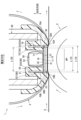
図1に示すように、定着装置Fは、電子写真方式の画像形成装置や、熱により箔を転写する箔転写装置などに使用されるものであり、加熱ユニット1と、加圧ユニットの一例としての加圧ローラ2とを備えている。定着装置Fは、加熱ユニット1と加圧ローラ2とで紙などの記録材Sを所定の方向に向けて搬送するように構成されている。以下では、定着装置Fにおける記録材Sの搬送方向を単に「搬送方向」といい、搬送方向に直交する記録材Sの幅方向を単に「幅方向」(図2参照)という。
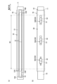
基板11は、セラミックの細長い長方形の板からなる。ヒータ10は、いわゆるセラミックヒータである。
支持部21は、ヒータ10、熱伝導部材30およびシート部材70を支持する部分であり、ヒータ10の形状に対応した幅方向に長い形状を有する。
案内部22は、支持部21の搬送方向における両側に設けられている。各案内部22は、ベルト3の内周面3Bに沿った案内面22Gを有する。案内部22は、幅方向に並ぶ複数の案内リブ22Aを有する。
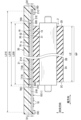
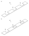
本体部71は、搬送方向に沿うように延びる部分である。シート部材70は、本体部71がヒータ10の裏側面16とホルダ20の支持部21との間に位置している。本体部71は、熱伝導部材30の反対面32とホルダ20の支持部21との間に位置している。熱伝導部材30は、ヒータ10の裏側面16と本体部71との間に位置している。
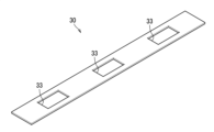
図7に示すように、第3実施形態において、熱伝導部材30は、対向方向に貫通する貫通穴33を有している。そして、温度検知部材50は、貫通穴33を通って、接触面51がシート部材70に接触している。詳しくは、接触面51は、シート部材70(本体部71)のシート裏側面71Bに第2シート部材52を介して接触している。
2 加圧ローラ
3 ベルト
3B 内周面
10 ヒータ
11 基板
12 抵抗発熱体
15 表側面
16 裏側面
20 ホルダ
21A 第1面
21B 第2面
23 挿入部
30 熱伝導部材
50 温度検知部材
51 接触面
70 シート部材
72 延出部
F 定着装置
NP ニップ部
S 記録材
Claims (15)
- 加熱ユニットと加圧ユニットとで記録材を搬送する定着装置であって、
前記加熱ユニットは、
基板と、前記基板に支持された抵抗発熱体とを有するヒータと、
前記ヒータの表側面に潤滑剤を介して接触する内周面を有し、前記ヒータの周りを回転する無端状のベルトと、
前記ヒータを保持するホルダと、
前記ヒータの前記表側面とは反対側の裏側面と前記ホルダとの間に位置し、前記基板よりも熱伝導率が小さいシート部材と、
前記ヒータの温度を検知するための温度検知部材であって、前記シート部材に対し前記ヒータの前記裏側面と反対側に位置する温度検知部材と、を備え、
前記シート部材の、記録材の搬送方向における長さは、前記ヒータの前記搬送方向における長さよりも長く、
前記シート部材は、前記搬送方向における少なくとも一方の端部に、前記ヒータの前記裏側面と前記シート部材とが向かい合う対向方向において前記表側面から離れる方向に延びる延出部を有し、
前記ホルダは、前記延出部が挿入される挿入部を有することを特徴とする定着装置。 - 前記延出部は、少なくとも、前記シート部材の前記搬送方向における下流側の端部に設けられていることを特徴とする請求項1に記載の定着装置。
- 前記挿入部は、底を有する溝であることを特徴とする請求項1または請求項2に記載の定着装置。
- 前記温度検知部材は、温度検知対象に接触する接触面を有し、
前記延出部は、前記対向方向において、前記接触面よりも、前記表側面から遠い位置まで延びていることを特徴とする請求項1から請求項3のいずれか1項に記載の定着装置。 - 加熱ユニットと加圧ユニットとで記録材を搬送する定着装置であって、
前記加熱ユニットは、
基板と、前記基板に支持された抵抗発熱体とを有するヒータと、
前記ヒータの表側面に潤滑剤を介して接触する内周面を有し、前記ヒータの周りを回転する無端状のベルトと、
前記ヒータを保持するホルダと、
前記ヒータの前記表側面とは反対側の裏側面と前記ホルダとの間に位置し、前記基板よりも熱伝導率が小さいシート部材と、
前記ヒータの温度を検知するための温度検知部材であって、前記シート部材に対し前記ヒータの前記裏側面と反対側に位置する温度検知部材と、
前記ヒータの前記裏側面と前記シート部材との間に位置し、前記基板よりも熱伝導率が大きい熱伝導部材と、を備え、
前記シート部材の、記録材の搬送方向における長さは、前記ヒータの前記搬送方向における長さよりも長く、かつ、前記熱伝導部材の前記搬送方向における長さよりも長く、
前記温度検知部材は、温度検知対象に接触する接触面が前記シート部材に接触していることを特徴とする定着装置。 - 前記シート部材と前記熱伝導部材との接触面積は、前記ヒータと前記熱伝導部材との接触面積以上であることを特徴とする請求項5に記載の定着装置。
- 前記シート部材は、前記ヒータの前記裏側面と接触し、
定着装置は、前記シート部材の、前記ヒータの前記裏側面と接触する面とは反対側の面と、前記ホルダとの間に位置し、前記基板よりも熱伝導率が大きい熱伝導部材を備え、
前記シート部材の前記搬送方向における長さは、前記熱伝導部材の前記搬送方向における長さよりも長いことを特徴とする請求項1から請求項4のいずれか1項に記載の定着装置。 - 前記ヒータは、前記熱伝導部材と接触していないことを特徴とする請求項7に記載の定着装置。
- 前記温度検知部材は、温度検知対象に接触する接触面が前記熱伝導部材に接触していることを特徴とする請求項7または請求項8に記載の定着装置。
- 加熱ユニットと加圧ユニットとで記録材を搬送する定着装置であって、
前記加熱ユニットは、
基板と、前記基板に支持された抵抗発熱体とを有するヒータと、
前記ヒータの表側面に潤滑剤を介して接触する内周面を有し、前記ヒータの周りを回転する無端状のベルトと、
前記ヒータを保持するホルダと、
前記ヒータの前記表側面とは反対側の裏側面と前記ホルダとの間に位置し、前記基板よりも熱伝導率が小さいシート部材と、
前記ヒータの温度を検知するための温度検知部材であって、前記シート部材に対し前記ヒータの前記裏側面と反対側に位置する温度検知部材と、
前記シート部材の、前記ヒータの前記裏側面と接触する面とは反対側の面と、前記ホルダとの間に位置し、前記基板よりも熱伝導率が大きい熱伝導部材と、を備え、
前記シート部材は、前記ヒータの前記裏側面と接触し、
前記シート部材の、記録材の搬送方向における長さは、前記ヒータの前記搬送方向における長さよりも長く、かつ、前記熱伝導部材の前記搬送方向における長さよりも長く、
前記熱伝導部材は、貫通穴または切欠を有し、
前記温度検知部材は、前記貫通穴または前記切欠を通って、温度検知対象に接触する接触面が前記シート部材に接触していることを特徴とする定着装置。 - 前記ホルダは、
前記シート部材と前記熱伝導部材を支持する第1面と、
前記搬送方向に直交する記録材の幅方向における前記第1面の外側に位置し、かつ、前記第1面よりも前記ヒータに近い位置に位置する第2面であって、前記ヒータの前記裏側面を支持する第2面とを有することを特徴とする請求項5から請求項10のいずれか1項に記載の定着装置。 - 前記第1面と前記第2面との段差は、前記シート部材の厚さと前記熱伝導部材の厚さの和以下であることを特徴とする請求項11に記載の定着装置。
- 加熱ユニットと加圧ユニットとで記録材を搬送する定着装置であって、
前記加熱ユニットは、
基板と、前記基板に支持された抵抗発熱体とを有するヒータと、
前記ヒータの表側面に潤滑剤を介して接触する内周面を有し、前記ヒータの周りを回転する無端状のベルトと、
前記ヒータを保持するホルダと、
前記ヒータの前記表側面とは反対側の裏側面と前記ホルダとの間に位置し、前記基板よりも熱伝導率が小さいシート部材と、
前記ヒータの温度を検知するための温度検知部材であって、前記シート部材に対し前記ヒータの前記裏側面と反対側に位置する温度検知部材と、を備え、
前記加圧ユニットは、前記ヒータとの間で前記ベルトを挟むことでニップ部を形成し、
前記シート部材の、記録材の搬送方向における長さは、前記ヒータの前記搬送方向における長さよりも長く、
前記シート部材の、前記搬送方向に直交する記録材の幅方向における長さは、前記ニップ部の前記幅方向における長さよりも長いことを特徴とする定着装置。 - 加熱ユニットと加圧ユニットとで記録材を搬送する定着装置であって、
前記加熱ユニットは、
基板と、前記基板に支持された抵抗発熱体とを有するヒータと、
前記ヒータの表側面に潤滑剤を介して接触する内周面を有し、前記ヒータの周りを回転する無端状のベルトと、
前記ヒータを保持するホルダと、
前記ヒータの前記表側面とは反対側の裏側面と前記ホルダとの間に位置し、前記基板よりも熱伝導率が小さいシート部材と、
前記ヒータの温度を検知するための温度検知部材であって、前記シート部材に対し前記ヒータの前記裏側面と反対側に位置する温度検知部材と、を備え、
前記シート部材の、記録材の搬送方向における長さは、前記ヒータの前記搬送方向における長さよりも長く、
前記温度検知部材は、複数設けられ、
複数の前記温度検知部材は、前記ヒータの前記裏側面と前記シート部材とが向かい合う対向方向から見て、同一の前記シート部材の輪郭の内側に配置されていることを特徴とする定着装置。 - 前記シート部材は、ポリイミドを含むフィルムであることを特徴とする請求項1から請求項14のいずれか1項に記載の定着装置。
Priority Applications (2)
| Application Number | Priority Date | Filing Date | Title |
|---|---|---|---|
| JP2021100088A JP7635648B2 (ja) | 2021-06-16 | 2021-06-16 | 定着装置 |
| US17/807,036 US11829090B2 (en) | 2021-06-16 | 2022-06-15 | Fixing device |
Applications Claiming Priority (1)
| Application Number | Priority Date | Filing Date | Title |
|---|---|---|---|
| JP2021100088A JP7635648B2 (ja) | 2021-06-16 | 2021-06-16 | 定着装置 |
Publications (2)
| Publication Number | Publication Date |
|---|---|
| JP2022191704A JP2022191704A (ja) | 2022-12-28 |
| JP7635648B2 true JP7635648B2 (ja) | 2025-02-26 |
Family
ID=84490361
Family Applications (1)
| Application Number | Title | Priority Date | Filing Date |
|---|---|---|---|
| JP2021100088A Active JP7635648B2 (ja) | 2021-06-16 | 2021-06-16 | 定着装置 |
Country Status (2)
| Country | Link |
|---|---|
| US (1) | US11829090B2 (ja) |
| JP (1) | JP7635648B2 (ja) |
Families Citing this family (2)
| Publication number | Priority date | Publication date | Assignee | Title |
|---|---|---|---|---|
| JP2023178543A (ja) * | 2022-06-06 | 2023-12-18 | キヤノン株式会社 | 像加熱装置、画像形成装置 |
| JP2025088111A (ja) * | 2023-11-30 | 2025-06-11 | ブラザー工業株式会社 | 加熱ユニット |
Citations (9)
| Publication number | Priority date | Publication date | Assignee | Title |
|---|---|---|---|---|
| JP2000172104A (ja) | 1998-12-01 | 2000-06-23 | Konica Corp | 定着装置 |
| JP2011145626A (ja) | 2010-01-18 | 2011-07-28 | Canon Inc | 像加熱装置及び画像形成装置 |
| JP2015197653A (ja) | 2014-04-03 | 2015-11-09 | コニカミノルタ株式会社 | 定着装置および画像形成装置 |
| JP2015219393A (ja) | 2014-05-19 | 2015-12-07 | キヤノン株式会社 | 画像加熱装置 |
| JP2017194719A (ja) | 2017-08-02 | 2017-10-26 | キヤノン株式会社 | 像加熱装置及びこの像加熱装置に用いられるヒータ |
| JP2019091028A (ja) | 2017-11-10 | 2019-06-13 | 富士ゼロックス株式会社 | 定着装置及び画像形成装置 |
| JP2019194649A (ja) | 2018-05-02 | 2019-11-07 | キヤノン株式会社 | 定着装置 |
| JP2020003611A (ja) | 2018-06-27 | 2020-01-09 | 株式会社沖データ | 定着装置及び画像形成装置 |
| JP2021039192A (ja) | 2019-09-02 | 2021-03-11 | 東芝テック株式会社 | 加熱装置、画像処理装置および加熱装置の製造方法 |
Family Cites Families (9)
| Publication number | Priority date | Publication date | Assignee | Title |
|---|---|---|---|---|
| KR101992768B1 (ko) * | 2012-10-30 | 2019-06-27 | 휴렛-팩커드 디벨롭먼트 컴퍼니, 엘.피. | 정착장치와 이를 가지는 화상형성장치 |
| JP6253508B2 (ja) | 2014-05-21 | 2017-12-27 | キヤノン株式会社 | 像加熱装置及び、この像加熱装置を搭載する画像形成装置 |
| JP6289344B2 (ja) | 2014-11-06 | 2018-03-07 | キヤノン株式会社 | 定着装置 |
| JP6579754B2 (ja) | 2015-01-27 | 2019-09-25 | キヤノン株式会社 | 定着装置 |
| JP6436447B2 (ja) | 2017-11-29 | 2018-12-12 | キヤノン株式会社 | 像加熱装置 |
| JP2020016825A (ja) | 2018-07-27 | 2020-01-30 | キヤノン株式会社 | 定着装置 |
| JP7172349B2 (ja) | 2018-09-20 | 2022-11-16 | 富士フイルムビジネスイノベーション株式会社 | 定着装置および画像形成装置 |
| JP2020086278A (ja) * | 2018-11-29 | 2020-06-04 | 株式会社リコー | 加熱装置、定着装置及び画像形成装置 |
| US10935912B1 (en) * | 2020-03-12 | 2021-03-02 | Toshiba Tec Kabushiki Kaisha | Heating device having first and second heat transfer units for an image forming unit |
-
2021
- 2021-06-16 JP JP2021100088A patent/JP7635648B2/ja active Active
-
2022
- 2022-06-15 US US17/807,036 patent/US11829090B2/en active Active
Patent Citations (9)
| Publication number | Priority date | Publication date | Assignee | Title |
|---|---|---|---|---|
| JP2000172104A (ja) | 1998-12-01 | 2000-06-23 | Konica Corp | 定着装置 |
| JP2011145626A (ja) | 2010-01-18 | 2011-07-28 | Canon Inc | 像加熱装置及び画像形成装置 |
| JP2015197653A (ja) | 2014-04-03 | 2015-11-09 | コニカミノルタ株式会社 | 定着装置および画像形成装置 |
| JP2015219393A (ja) | 2014-05-19 | 2015-12-07 | キヤノン株式会社 | 画像加熱装置 |
| JP2017194719A (ja) | 2017-08-02 | 2017-10-26 | キヤノン株式会社 | 像加熱装置及びこの像加熱装置に用いられるヒータ |
| JP2019091028A (ja) | 2017-11-10 | 2019-06-13 | 富士ゼロックス株式会社 | 定着装置及び画像形成装置 |
| JP2019194649A (ja) | 2018-05-02 | 2019-11-07 | キヤノン株式会社 | 定着装置 |
| JP2020003611A (ja) | 2018-06-27 | 2020-01-09 | 株式会社沖データ | 定着装置及び画像形成装置 |
| JP2021039192A (ja) | 2019-09-02 | 2021-03-11 | 東芝テック株式会社 | 加熱装置、画像処理装置および加熱装置の製造方法 |
Also Published As
| Publication number | Publication date |
|---|---|
| JP2022191704A (ja) | 2022-12-28 |
| US11829090B2 (en) | 2023-11-28 |
| US20220404746A1 (en) | 2022-12-22 |
Similar Documents
| Publication | Publication Date | Title |
|---|---|---|
| US9766578B2 (en) | Fixing device | |
| US9513586B2 (en) | Image heating apparatus having film, back-up member forming a nip with the film, a heater, and heat conductive members configured to be brought into contact with heater surface opposite to the surface of the heater brought into contact with the film | |
| US10095165B2 (en) | Fixing apparatus for fixing a toner image to a recording medium | |
| CN100437387C (zh) | 加热定影装置及图像形成装置 | |
| US20150023704A1 (en) | Image fixing apparatus | |
| JP7635648B2 (ja) | 定着装置 | |
| CN105388738A (zh) | 定影装置 | |
| JP2020016825A (ja) | 定着装置 | |
| JP6882079B2 (ja) | 定着装置 | |
| CN111948927B (zh) | 定影装置 | |
| JP7600751B2 (ja) | 加熱ユニット | |
| JP7004395B2 (ja) | ヒータ | |
| JPH05313528A (ja) | 熱定着装置 | |
| JP7625866B2 (ja) | 加熱ユニット | |
| US11640129B2 (en) | Heating unit | |
| JP7643157B2 (ja) | 加熱ユニット | |
| JP7625893B2 (ja) | 加熱ユニット | |
| JP7813650B2 (ja) | 定着装置 | |
| JP7563233B2 (ja) | 加熱ユニット | |
| JP2025034950A (ja) | 定着装置 | |
| JP2025034949A (ja) | 定着装置 | |
| JP2025033884A (ja) | 定着装置及び画像形成装置 | |
| JP2022163870A (ja) | 加熱ユニット | |
| JP2025034948A (ja) | 定着装置 | |
| JP7613225B2 (ja) | 加熱ユニット |
Legal Events
| Date | Code | Title | Description |
|---|---|---|---|
| A621 | Written request for application examination |
Free format text: JAPANESE INTERMEDIATE CODE: A621 Effective date: 20240514 |
|
| A977 | Report on retrieval |
Free format text: JAPANESE INTERMEDIATE CODE: A971007 Effective date: 20241120 |
|
| A131 | Notification of reasons for refusal |
Free format text: JAPANESE INTERMEDIATE CODE: A131 Effective date: 20241203 |
|
| A521 | Request for written amendment filed |
Free format text: JAPANESE INTERMEDIATE CODE: A523 Effective date: 20241226 |
|
| TRDD | Decision of grant or rejection written | ||
| A01 | Written decision to grant a patent or to grant a registration (utility model) |
Free format text: JAPANESE INTERMEDIATE CODE: A01 Effective date: 20250114 |
|
| A61 | First payment of annual fees (during grant procedure) |
Free format text: JAPANESE INTERMEDIATE CODE: A61 Effective date: 20250127 |
|
| R150 | Certificate of patent or registration of utility model |
Ref document number: 7635648 Country of ref document: JP Free format text: JAPANESE INTERMEDIATE CODE: R150 |