JP6861425B2 - H形鋼の接合構造 - Google Patents
H形鋼の接合構造 Download PDFInfo
- Publication number
- JP6861425B2 JP6861425B2 JP2019548235A JP2019548235A JP6861425B2 JP 6861425 B2 JP6861425 B2 JP 6861425B2 JP 2019548235 A JP2019548235 A JP 2019548235A JP 2019548235 A JP2019548235 A JP 2019548235A JP 6861425 B2 JP6861425 B2 JP 6861425B2
- Authority
- JP
- Japan
- Prior art keywords
- web
- shaped steel
- steel
- plate
- connecting plate
- Prior art date
- Legal status (The legal status is an assumption and is not a legal conclusion. Google has not performed a legal analysis and makes no representation as to the accuracy of the status listed.)
- Active
Links
Images


Classifications
-
- E—FIXED CONSTRUCTIONS
- E04—BUILDING
- E04B—GENERAL BUILDING CONSTRUCTIONS; WALLS, e.g. PARTITIONS; ROOFS; FLOORS; CEILINGS; INSULATION OR OTHER PROTECTION OF BUILDINGS
- E04B1/00—Constructions in general; Structures which are not restricted either to walls, e.g. partitions, or floors or ceilings or roofs
- E04B1/18—Structures comprising elongated load-supporting parts, e.g. columns, girders, skeletons
- E04B1/24—Structures comprising elongated load-supporting parts, e.g. columns, girders, skeletons the supporting parts consisting of metal
- E04B1/2403—Connection details of the elongated load-supporting parts
-
- E—FIXED CONSTRUCTIONS
- E04—BUILDING
- E04B—GENERAL BUILDING CONSTRUCTIONS; WALLS, e.g. PARTITIONS; ROOFS; FLOORS; CEILINGS; INSULATION OR OTHER PROTECTION OF BUILDINGS
- E04B1/00—Constructions in general; Structures which are not restricted either to walls, e.g. partitions, or floors or ceilings or roofs
- E04B1/38—Connections for building structures in general
- E04B1/58—Connections for building structures in general of bar-shaped building elements
- E04B1/5806—Connections for building structures in general of bar-shaped building elements with a cross-section having an open profile
- E04B1/5812—Connections for building structures in general of bar-shaped building elements with a cross-section having an open profile of substantially I - or H - form
-
- E—FIXED CONSTRUCTIONS
- E04—BUILDING
- E04B—GENERAL BUILDING CONSTRUCTIONS; WALLS, e.g. PARTITIONS; ROOFS; FLOORS; CEILINGS; INSULATION OR OTHER PROTECTION OF BUILDINGS
- E04B1/00—Constructions in general; Structures which are not restricted either to walls, e.g. partitions, or floors or ceilings or roofs
- E04B1/18—Structures comprising elongated load-supporting parts, e.g. columns, girders, skeletons
- E04B1/24—Structures comprising elongated load-supporting parts, e.g. columns, girders, skeletons the supporting parts consisting of metal
- E04B1/2403—Connection details of the elongated load-supporting parts
- E04B2001/2415—Brackets, gussets, joining plates
-
- E—FIXED CONSTRUCTIONS
- E04—BUILDING
- E04B—GENERAL BUILDING CONSTRUCTIONS; WALLS, e.g. PARTITIONS; ROOFS; FLOORS; CEILINGS; INSULATION OR OTHER PROTECTION OF BUILDINGS
- E04B1/00—Constructions in general; Structures which are not restricted either to walls, e.g. partitions, or floors or ceilings or roofs
- E04B1/18—Structures comprising elongated load-supporting parts, e.g. columns, girders, skeletons
- E04B1/24—Structures comprising elongated load-supporting parts, e.g. columns, girders, skeletons the supporting parts consisting of metal
- E04B1/2403—Connection details of the elongated load-supporting parts
- E04B2001/2418—Details of bolting
-
- E—FIXED CONSTRUCTIONS
- E04—BUILDING
- E04B—GENERAL BUILDING CONSTRUCTIONS; WALLS, e.g. PARTITIONS; ROOFS; FLOORS; CEILINGS; INSULATION OR OTHER PROTECTION OF BUILDINGS
- E04B1/00—Constructions in general; Structures which are not restricted either to walls, e.g. partitions, or floors or ceilings or roofs
- E04B1/18—Structures comprising elongated load-supporting parts, e.g. columns, girders, skeletons
- E04B1/24—Structures comprising elongated load-supporting parts, e.g. columns, girders, skeletons the supporting parts consisting of metal
- E04B1/2403—Connection details of the elongated load-supporting parts
- E04B2001/2448—Connections between open section profiles
-
- E—FIXED CONSTRUCTIONS
- E04—BUILDING
- E04B—GENERAL BUILDING CONSTRUCTIONS; WALLS, e.g. PARTITIONS; ROOFS; FLOORS; CEILINGS; INSULATION OR OTHER PROTECTION OF BUILDINGS
- E04B1/00—Constructions in general; Structures which are not restricted either to walls, e.g. partitions, or floors or ceilings or roofs
- E04B1/18—Structures comprising elongated load-supporting parts, e.g. columns, girders, skeletons
- E04B1/24—Structures comprising elongated load-supporting parts, e.g. columns, girders, skeletons the supporting parts consisting of metal
- E04B1/2403—Connection details of the elongated load-supporting parts
- E04B2001/2457—Beam to beam connections
-
- E—FIXED CONSTRUCTIONS
- E04—BUILDING
- E04B—GENERAL BUILDING CONSTRUCTIONS; WALLS, e.g. PARTITIONS; ROOFS; FLOORS; CEILINGS; INSULATION OR OTHER PROTECTION OF BUILDINGS
- E04B1/00—Constructions in general; Structures which are not restricted either to walls, e.g. partitions, or floors or ceilings or roofs
- E04B1/38—Connections for building structures in general
- E04B1/58—Connections for building structures in general of bar-shaped building elements
- E04B2001/5875—Connections for building structures in general of bar-shaped building elements using exterior clamping plates or shells
Landscapes
- Engineering & Computer Science (AREA)
- Architecture (AREA)
- Physics & Mathematics (AREA)
- Electromagnetism (AREA)
- Civil Engineering (AREA)
- Structural Engineering (AREA)
- Joining Of Building Structures In Genera (AREA)
Description
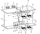
<第1実施形態>
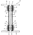
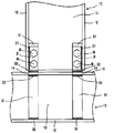
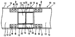
図1及び図2に示す第1実施形態のH形鋼の接合構造では、H形鋼10と、隣り合う鋼材としてのH形鋼11とを接合する状態を示しており、伝達プレート2がフランジ12の裏面に長手方向に沿って溶接されるとともに、ウエッブ13の表面に密着するように設けられている。
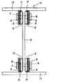
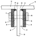
<第2実施形態>
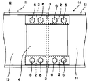
本発明においては、図4、図5に示すような第2実施形態のH形鋼の接合構造とすることもできる。第2実施形態では、伝達プレート2がウエッブ13の表面から連結プレート3の厚み分の間隔を空けてフランジ12の裏面に溶接されて設けられ、連結プレート3が伝達プレート2とウエッブ13の間に密着して設けられている。即ち、連結プレート3は伝達プレート2とウエッブ13で挟まれる構成となっている。
<第3−1実施形態>
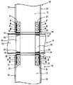
更に本発明においては、伝達プレート2が連結プレート3の厚み分の間隔を空けて複数設け、連結プレート3をウエッブ13と伝達プレート2の間及び/又は複数の伝達プレート2の間に密着して挟むように設けることができる。
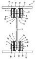
<第3−2実施形態>
また、第3−2実施形態として、図7に示すように、伝達プレート2aを第2実施形態と同様にウエッブ13の表面から連結プレート3aの厚み分の間隔を空けてフランジ12の裏面に溶接して設け、更に、その外側に連結プレート3bの厚み分の間隔を空けて伝達プレート2bを設け、連結プレート3aを伝達プレート2aとウエッブ13の間に密着して設けるとともに、伝達プレート2aと2枚目の伝達プレート2bの間にさらに連結プレート3bを設ける構成とすることもできる。この構成によれば、ウエッブ13の両側で4枚の連結プレート3が接合され、合計8面の摩擦面により8面剪断摩擦接合されるため、より強力に接合することができる。
<第4実施形態>
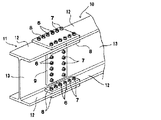
本発明において、連結プレート3の断面だけで剪断力を伝達できない場合や、更に高い剪断力の伝達の要請があるような場合には、図8、図9に示すように、上下の連結プレート3の間又は連結プレートの外に各々を繋ぐ剪断連結プレート4を挟んで設けることができる。これにより、大きい剪断力を伝達することが可能となる。
<第5実施形態>
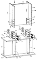
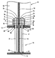
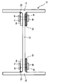
図10は第5実施形態の分解斜視図を示しており、図11は、図10の接合後のB−B断面図を示している。第5実施形態では、水平に配設された構造物としての梁状のH形鋼15のフランジ12に、垂直に柱状のH形鋼10を接合する状態を示している。垂直に配設するH形鋼10の端部には、第1実施形態と同様に伝達プレート2がフランジ12の裏面に長手方向に沿って溶接され、ウエッブ13の表面に密着するように設けられている。伝達プレート2のフランジ12の裏面への溶接は第1実施形態と同様の構成で行うことができる。
<第6実施形態>
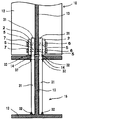
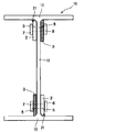
本発明においては、図12、図13に示すような第6実施形態のH形鋼の接合構造とすることもできる。第6実施形態では、垂直に配設するH形鋼10の端部には第2実施形態と同様に伝達プレート2がウエッブ13の表面から連結プレート31の厚み分の間隔を空けてフランジ12の裏面に溶接されて設けられ、連結プレート31の端部が伝達プレート2とウエッブ13の間に密着して設けられている。即ち、連結プレート3は伝達プレート2とウエッブ13で挟まれて、これをボルト接合した構成となっている。また、連結プレート31は、水平に配設されるH形鋼15の上側のフランジ12に設けた挿通孔14に挿通してウエッブ13に密着して設けられ、さらに上下のフランジ12に溶接されている。
<第7−1実施形態>
更に本発明においては、第7−1実施形態として、垂直に配設されるH形鋼の端部において、第3−1実施形態と同様に、伝達プレート2が連結プレート3の厚み分の間隔を空けて複数設けられており、連結プレート3が、ウエッブ13と伝達プレート2の間及び/又は複数の伝達プレート2の間に密着して挟まれるように設けることができる。
<第7−2実施形態>
また、図示しない他の第7−2実施形態として、第3−2実施形態と同様に、伝達プレート2をウエッブ13の表面から連結プレート31の厚み分の間隔を空けてフランジ12の裏面に溶接して設け、更に、その外側に連結プレート31の厚み分の間隔を空けて伝達プレート2を設け、連結プレート31を伝達プレート2とウエッブ13の間に密着して設けるとともに、2枚の伝達プレート2の間にさらに連結プレート31を設ける構成とすることもできる。この構成によれば、ウエッブ13の両側で4枚の連結プレート31が接合され、合計8面の摩擦面により8面剪断摩擦接合されるため、より強力に接合することができる。なお、水平に配設されるH形鋼15に対する連結プレート31の溶接位置は、上記の状態となる位置である。
<第8実施形態>
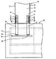
また、第8実施形態として図15に示すように、基礎16の構造物の柱脚アンカーとしての基礎定着板18に、連結プレート31を垂直方向に向けて溶接し、これを鉄筋17などで囲み、コンクリートで強固に一体にすることもできる。そして、基礎16から突出させた連結プレート31の端を垂直に配設されたH形鋼10のウエッブ13及び連結プレート2を合わせてボルト結合する。なお、この際、H形鋼10の伝達プレート2及び基礎16に埋込まれた構造物である基礎定着板18に溶接された連結プレート31の配置構成は、設計等に応じて上記第5実施形態〜第7実施形態のいずれの構成とすることもできる。<第9実施形態>
さらに、第9実施形態として、図16に示すように、水平に配設したH形鋼15において、連結プレート31を上下のフランジ12に設けた挿通孔14に挿通させて溶接し、水平に配設したH形鋼15に対し垂直に配設したH形鋼10で上下から挟むように接合することもできる。なお、この構成においても、H形鋼10の伝達プレート2及びH形鋼15に溶接された連結プレート31の配置構成は、設計等に応じて上記第5実施例〜第7実施例の何れの構成とすることができる。
<第10実施形態>
さらに第10実施形態として、図17に示すように、水平に配設したH形鋼15のウエッブ13に対して垂直方向にスチフナ19を設けるとともに、ウエッブ13に挿通させた連結プレート31をスチフナ19に溶接又はボルト接合し、水平に配設したH形鋼15に対し水平、直角に配設したH形鋼10、11で左右から挟むようにボルト接合することもできる。
<第11実施形態>
図18に示す第11実施形態のH形鋼の接合構造では、伝達プレート2がフランジ12の裏面に長手方向に沿って溶接されるとともに、ウエッブ13の表面に密着するように設けられている。そして、伝達プレート2が配設されたウエッブ13の反対側に、連結プレート3がウエッブ13の表面に密着するように設けられている。
<第12実施形態>
さらに、図19に示す第12実施形態のH形鋼の接合構造では、図18に示す連結プレート3とウエッブ13の片面の一面剪断摩擦接合において、フランジ12に溶接される伝達プレート2及び連結プレート3の配設位置を上下でウエッブの13の反対側に設けている。第12実施形態によれば、連結プレート3とウエッブ13の片面の一面剪断摩擦接合が上下でバランスがとれ、芯ずれ(応力の中心のずれ)を解消することが可能となる。
Claims (13)
- H形鋼と隣り合う少なくともフランジとウエッブを有する鋼材の端部同士を接合するH形鋼の接合構造であって、
前記H形鋼と前記鋼材の少なくともウエッブの片側で、かつ、該ウエッブの表面に対して平行に配設され、フランジの裏面に溶接された伝達プレートと、
該伝達プレートに密着して設けられ、前記H形鋼と前記鋼材を繋ぐ連結プレートを備え、
前記H形鋼と前記鋼材のウエッブ及び前記伝達プレートが、前記連結プレートを介してボルト接合されていることを特徴とするH形鋼の接合構造。 - H形鋼と隣り合う少なくともフランジとウエッブを有する鋼材の端部同士を接合するH形鋼の接合構造であって、
前記H形鋼と前記鋼材の少なくともウエッブの片側で、かつ、該ウエッブの表面に対して平行に配設され、フランジの裏面に溶接された伝達プレートと、
該伝達プレートが配設された側のウエッブとは反対側に、前記H形鋼と前記鋼材を繋ぐ連結プレートを備え、
前記H形鋼と前記鋼材のウエッブ及び前記伝達プレートが、前記連結プレートを介してボルト接合されていることを特徴とするH形鋼の接合構造。 - 前記H形鋼と前記鋼材の前記伝達プレートが、前記ウエッブの表面に密着して配設されており、前記連結プレートが、前記伝達プレートの表面又は前記ウエッブの表面に密着して配設されていることを特徴とする請求項1又は2に記載のH形鋼の接合構造。
- 前記H形鋼と前記鋼材の前記伝達プレートが、前記ウエッブの表面から前記連結プレートの厚み分の間隔を空けてフランジの裏面に溶接されて配設されており、
前記連結プレートが、前記伝達プレートと前記ウエッブの間に密着して挟まれるように配設されていることを特徴とする請求項1又は2に記載のH形鋼の接合構造。 - 前記H形鋼と前記鋼材の前記伝達プレートが前記連結プレートの厚み分の間隔を空けて複数配設されており、
前記連結プレートが、前記ウエッブと前記伝達プレートの間、及び/又は、前記複数の伝達プレートの間に密着して挟まれるように配設されていることを特徴とする請求項1又は2に記載のH形鋼の接合構造。 - 前記H形鋼と前記鋼材の上下の前記伝達プレートと上下の前記連結プレートの間に、各々を繋ぐ剪断連結プレートが設けられていることを特徴とする請求項1又は2に記載のH形鋼の接合構造。
- 前記鋼材が、H形鋼、溝形鋼、Z形鋼、I形鋼のいずれかであることを特徴とする請求項1から6のいずれか一項に記載のH形鋼の接合構造。
- H形鋼と構造物を接合するH形鋼の接合構造であって、
前記H形鋼の少なくともウエッブの片側で、かつ、該ウエッブの表面に対して平行に配設され、フランジの裏面に溶接された伝達プレートと、
該伝達プレートに密着して設けられ、前記H形鋼と前記構造物を繋ぐ連結プレートを備え、
前記連結プレートの一部が前記構造物に溶接またはボルト接合されており、少なくとも一端部が前記H形鋼のウエッブ及び前記伝達プレートとボルト接合されていることを特徴とするH形鋼の接合構造。 - H形鋼と構造物を接合するH形鋼の接合構造であって、
前記H形鋼の少なくともウエッブの片側で、かつ、該ウエッブの表面に対して平行に配設され、フランジの裏面に溶接された伝達プレートと、
該伝達プレートが配設された側のウエッブとは反対側に、前記H形鋼と前記構造物を繋ぐ連結プレートを備え、
前記連結プレートの一部が前記構造物に溶接またはボルト接合されており、少なくとも一端部が前記H形鋼のウエッブ及び前記伝達プレートとボルト接合されていることを特徴とするH形鋼の接合構造。 - 前記H形鋼の前記伝達プレートが、前記ウエッブの表面に密着して配設されており、
前記連結プレートが前記構造物に溶接され、少なくとも一端部が前記伝達プレートの表面又は前記ウエッブの表面に密着して配設されていることを特徴とする請求項8又は9に記載のH形鋼の接合構造。 - 前記H形鋼の前記伝達プレートが、前記ウエッブの表面から前記連結プレートの厚み分の間隔を空けてフランジの裏面に溶接されて配設されており、
前記連結プレートが前記構造物に溶接され、少なくとも一端部が前記伝達プレートと前記ウエッブの間に密着して挟まれるように配設されていることを特徴とする請求項8又は9に記載のH形鋼の接合構造。 - 前記H形鋼の前記伝達プレートが前記連結プレートの厚み分の間隔を空けて複数配設されており、
前記連結プレートが前記構造物に溶接され、少なくとも一端部が前記ウエッブと前記伝達プレートの間、及び/又は、前記複数の伝達プレートの間に密着して挟まれるように配設されていることを特徴とする請求項8又は9に記載のH形鋼の接合構造。 - 前記構造物が、H形鋼、溝形鋼、Z形鋼、I形鋼、角形鋼管、基礎定着板のいずれかであることを特徴とする請求項8から12のいずれか一項に記載のH形鋼の接合構造。
Applications Claiming Priority (3)
| Application Number | Priority Date | Filing Date | Title |
|---|---|---|---|
| JP2017199349 | 2017-10-13 | ||
| JP2017199349 | 2017-10-13 | ||
| PCT/JP2018/037911 WO2019074050A1 (ja) | 2017-10-13 | 2018-10-11 | H形鋼の接合構造 |
Publications (2)
| Publication Number | Publication Date |
|---|---|
| JPWO2019074050A1 JPWO2019074050A1 (ja) | 2020-12-10 |
| JP6861425B2 true JP6861425B2 (ja) | 2021-04-21 |
Family
ID=66100749
Family Applications (1)
| Application Number | Title | Priority Date | Filing Date |
|---|---|---|---|
| JP2019548235A Active JP6861425B2 (ja) | 2017-10-13 | 2018-10-11 | H形鋼の接合構造 |
Country Status (6)
| Country | Link |
|---|---|
| US (1) | US11598086B2 (ja) |
| EP (1) | EP3696336B1 (ja) |
| JP (1) | JP6861425B2 (ja) |
| CN (1) | CN111433416B (ja) |
| SG (1) | SG11202003238SA (ja) |
| WO (1) | WO2019074050A1 (ja) |
Families Citing this family (13)
| Publication number | Priority date | Publication date | Assignee | Title |
|---|---|---|---|---|
| CN110439112B (zh) * | 2019-08-20 | 2024-05-28 | 华南理工大学 | 一种由铰接柱与弹性复位梁组合的免预应力韧性钢结构 |
| JP2021165462A (ja) * | 2020-04-06 | 2021-10-14 | 構法開発株式会社 | 溝形鋼の接合構造 |
| CN111441621A (zh) * | 2020-05-11 | 2020-07-24 | 上海森松制药设备工程有限公司 | 模块化厂房 |
| CN112031163A (zh) * | 2020-08-13 | 2020-12-04 | 上海现代建筑设计集团工程建设咨询有限公司 | 一种便于拆装的结构节点及连接方法 |
| JP7704337B2 (ja) * | 2020-10-29 | 2025-07-08 | 構法開発株式会社 | 鋼材の接合構造 |
| JP7713812B2 (ja) * | 2021-06-14 | 2025-07-28 | 戸田建設株式会社 | 鋼コンクリート合成構造に用いられる鋼材の接合構造 |
| JP7437367B2 (ja) * | 2021-10-22 | 2024-02-22 | 日本コンクリート工業株式会社 | 継手装置および被接続部材の接続方法 |
| FI131985B1 (en) * | 2022-11-10 | 2026-03-25 | Konecranes Global Oy | Connection arrangement and method for connecting main beam parts |
| CN117266361B (zh) * | 2023-11-15 | 2024-02-02 | 中铁九局集团有限公司 | 一种基于bim技术的钢结构节点连接结构 |
| JP7687378B1 (ja) | 2023-12-20 | 2025-06-03 | 積水ハウス株式会社 | 鋼材の接続構造及び建築物 |
| US12091879B1 (en) * | 2024-03-12 | 2024-09-17 | King Saud University | Beam-column moment connection structure |
| CN119593501B (zh) * | 2024-11-08 | 2025-09-26 | 浙江融商绿色制造有限公司 | 一种高强度钢结构组件及激光焊接工艺 |
| US12535116B1 (en) * | 2024-12-31 | 2026-01-27 | University Of Sharjah | Radially perforated damper for beam to column damping |
Family Cites Families (48)
| Publication number | Priority date | Publication date | Assignee | Title |
|---|---|---|---|---|
| GB1253033A (ja) * | 1968-01-23 | 1971-11-10 | ||
| US3977801A (en) * | 1974-11-22 | 1976-08-31 | Thomas Philip Murphy | Connector for structural members |
| US4014089A (en) * | 1975-02-21 | 1977-03-29 | Kajima Corporation | Method of connecting beams and columns of steel frame construction |
| JPH05179703A (ja) | 1992-01-07 | 1993-07-20 | Sekisui House Ltd | H型鋼の接合装置 |
| JPH06173340A (ja) | 1992-12-07 | 1994-06-21 | Taisei Corp | 鉄骨梁の接合構造 |
| JPH0734551A (ja) * | 1993-07-09 | 1995-02-03 | Hirobumi Furukawa | 鉄骨構造の継手における接合材及び接合法 |
| US5660017A (en) * | 1994-12-13 | 1997-08-26 | Houghton; David L. | Steel moment resisting frame beam-to-column connections |
| US5577353A (en) * | 1995-01-27 | 1996-11-26 | Simpson; William G. | Steel frame building system and truss assembly for use therein |
| US6237303B1 (en) * | 1995-04-11 | 2001-05-29 | Seismic Structural Design | Steel frame stress reduction connection |
| US6073405A (en) * | 1995-12-22 | 2000-06-13 | Icf Kaiser Engineers, Inc. | Fitting for effecting bolted connection between a beam and a column in a steel frame structure |
| JPH11210093A (ja) * | 1998-01-21 | 1999-08-03 | Nippon Steel Corp | 構造部材の接合構造 |
| US6138427A (en) * | 1998-08-28 | 2000-10-31 | Houghton; David L. | Moment resisting, beam-to-column connection |
| US7155874B2 (en) * | 2001-02-15 | 2007-01-02 | Dae-Jun Lee | Tubular structure and modular building assembly using the same |
| US6739099B2 (en) * | 2001-06-06 | 2004-05-25 | Nippon Steel Corporation | Column-and-beam join structure |
| US7497054B2 (en) * | 2001-06-06 | 2009-03-03 | Nippon Steel Corporation | Column-and-beam join structure |
| US6591573B2 (en) * | 2001-07-12 | 2003-07-15 | David L. Houghton | Gusset plates connection of beam to column |
| US6802169B2 (en) * | 2002-03-18 | 2004-10-12 | Robert J. Simmons | Building frame structure |
| US20050055969A1 (en) * | 2002-03-18 | 2005-03-17 | Simmons Robert J. | Building frame structure |
| US6829872B2 (en) * | 2002-03-19 | 2004-12-14 | William J. Wahlsteen | Process and device for connecting I-beams |
| JP4197460B2 (ja) * | 2002-09-12 | 2008-12-17 | 新日本製鐵株式会社 | 無耐火被覆高力ボルト接合部構造 |
| JP4376088B2 (ja) * | 2003-02-28 | 2009-12-02 | 新日本製鐵株式会社 | 梁継手構造 |
| US7178296B2 (en) * | 2004-03-19 | 2007-02-20 | Houghton David L | Structural joint connection providing blast resistance and a beam-to-beam connection resistant to moments, tension and torsion across a column |
| JP2006051522A (ja) * | 2004-08-11 | 2006-02-23 | Okudo Kinzoku:Kk | H型鋼溶接継手構造 |
| JP4754397B2 (ja) * | 2006-04-24 | 2011-08-24 | 新日本製鐵株式会社 | H形鋼同士の接合構造および接合方法 |
| US20080022624A1 (en) * | 2006-07-25 | 2008-01-31 | Hanson Courtney J | Joist support |
| US7607273B2 (en) * | 2006-09-08 | 2009-10-27 | Henderson Andrew G | Building member |
| JP4203533B1 (ja) * | 2008-03-05 | 2009-01-07 | 株式会社アイ.テック | 鉄骨柱及び鉄骨梁の接合構造 |
| JP2009280971A (ja) * | 2008-05-19 | 2009-12-03 | Shimizu Corp | プレキャストコンクリート柱とプレキャストコンクリート梁との接合構造。 |
| US8146322B2 (en) * | 2008-08-21 | 2012-04-03 | Mitek Holdings, Inc. | Building structure, method of making, and components |
| CN201687086U (zh) * | 2010-05-06 | 2010-12-29 | 福州大学 | 新型钢梁柱连接结构 |
| US9540801B2 (en) * | 2012-07-09 | 2017-01-10 | Oz-Post International, LLC | Multi-piece truss plate for use in joining two structural members |
| US20140083042A1 (en) * | 2012-09-27 | 2014-03-27 | Best Nature Co., Ltd. | Junction structure between structures and beam junction method |
| CA2898340C (en) * | 2012-11-30 | 2018-02-13 | Mitek Holdings, Inc. | Gusset plate connection of beam to column |
| US9506239B2 (en) * | 2012-11-30 | 2016-11-29 | Mitek Holdings, Inc. | Gusset plate connection in bearing of beam to column |
| WO2014144212A1 (en) * | 2013-03-15 | 2014-09-18 | Green James E | Self-supporting and load bearing structural joint |
| US9249593B2 (en) * | 2013-03-28 | 2016-02-02 | Magnum Piering, Inc. | Systems for elevating a building structure above grade, and related methods |
| TWI509167B (zh) * | 2013-12-10 | 2015-11-21 | China Steel Corp | Energy dissipation joint assembly and the use of its seismic structure |
| KR101658020B1 (ko) * | 2014-02-07 | 2016-09-30 | 한국해양대학교 산학협력단 | 콘크리트 구조물용 파일 접합 구조체 |
| CA3007316C (en) * | 2015-12-09 | 2020-07-21 | Brigham Young University | Beam-to-column connection systems and moment-resisting frames including the same |
| US10689876B2 (en) * | 2015-12-09 | 2020-06-23 | Durafuse Frames, Llc | Beam-to-column connection systems and moment-resisting frames including the same |
| CN105569204B (zh) * | 2016-02-01 | 2018-05-18 | 中国地震局工程力学研究所 | 一种可更换的梁柱节点地震损伤控制装置 |
| CN205822453U (zh) * | 2016-05-13 | 2016-12-21 | 三一住工有限公司 | 型钢的连接结构 |
| CN206034642U (zh) * | 2016-08-25 | 2017-03-22 | 中冶建筑研究总院有限公司 | 一种钢柱法兰式拼接节点 |
| CN206052956U (zh) * | 2016-08-31 | 2017-03-29 | 江西杭萧钢构有限公司 | 一种h型悬臂钢梁柱拼接结构 |
| JP6863776B2 (ja) * | 2017-03-07 | 2021-04-21 | 積水化学工業株式会社 | 継手構造および建築用構造体 |
| KR101848699B1 (ko) * | 2017-09-22 | 2018-04-16 | (주)피에스테크 | 용접 없이 기둥과 보의 접합이 가능한 접합부 코어 및 이를 이용한 기둥과 보의 접합 방법 |
| US10323430B1 (en) * | 2017-12-15 | 2019-06-18 | Avtar Pall | Friction damper for a building structure |
| CN108193832A (zh) * | 2017-12-29 | 2018-06-22 | 上海建工集团股份有限公司 | 一种工字型钢梁装配式连接节点及其施工方法 |
-
2018
- 2018-10-11 CN CN201880066586.8A patent/CN111433416B/zh active Active
- 2018-10-11 SG SG11202003238SA patent/SG11202003238SA/en unknown
- 2018-10-11 EP EP18867126.7A patent/EP3696336B1/en active Active
- 2018-10-11 WO PCT/JP2018/037911 patent/WO2019074050A1/ja not_active Ceased
- 2018-10-11 US US16/754,867 patent/US11598086B2/en active Active
- 2018-10-11 JP JP2019548235A patent/JP6861425B2/ja active Active
Also Published As
| Publication number | Publication date |
|---|---|
| WO2019074050A1 (ja) | 2019-04-18 |
| EP3696336A4 (en) | 2021-06-23 |
| CN111433416A (zh) | 2020-07-17 |
| US20200318342A1 (en) | 2020-10-08 |
| EP3696336A1 (en) | 2020-08-19 |
| SG11202003238SA (en) | 2020-05-28 |
| EP3696336B1 (en) | 2024-04-17 |
| CN111433416B (zh) | 2021-09-28 |
| JPWO2019074050A1 (ja) | 2020-12-10 |
| US11598086B2 (en) | 2023-03-07 |
Similar Documents
| Publication | Publication Date | Title |
|---|---|---|
| JP6861425B2 (ja) | H形鋼の接合構造 | |
| CN107208413B (zh) | 钢梁接合结构 | |
| CN107407086A (zh) | 具备预制板与锚通道的预制混凝土构件 | |
| KR101509100B1 (ko) | 시공성이 우수한 에이치빔 어댑터 | |
| JP2016176216A (ja) | 仕口部の接合装置、仕口部の接合構造、及び仕口部の接合方法 | |
| KR20130139029A (ko) | H 형강을 이용한 건축 모듈러 기둥 접합구조 | |
| JP2020037774A (ja) | 柱梁接合構造及びその柱梁接合構造を備えた建物 | |
| KR20040020444A (ko) | 철골건축물의 기둥과 h형강 보의 접합구조 및 그 접합방법 | |
| JP2018084052A (ja) | 複合梁における異種材料の接合方法と接合構造 | |
| JP2020076226A (ja) | 形鋼、床構造及び床構造の施工方法 | |
| JP2010159565A (ja) | 柱梁接合部および柱梁接合部の補強金物 | |
| JP6954222B2 (ja) | 小梁端接合構造、および小梁端接合構造の施工方法 | |
| JP2024041990A (ja) | 溝形鋼の接合構造 | |
| JP4710067B2 (ja) | 柱梁接合構造 | |
| JP2014214497A (ja) | 木質梁接合構造及び木質梁接合方法 | |
| JP7406764B2 (ja) | 鋼管柱の接合構造 | |
| JP6645328B2 (ja) | H形鋼の接合構造及びそれに用いられるh形鋼 | |
| JP2024048567A (ja) | 大梁と小梁の接合構造 | |
| JP7704337B2 (ja) | 鋼材の接合構造 | |
| JP6353647B2 (ja) | 免震装置接合構造 | |
| JP2019027151A (ja) | 梁接合構造 | |
| JP6886830B2 (ja) | 座屈拘束ブレース、柱梁接続部の補強構造、及び建物 | |
| JPH09189075A (ja) | 角形鋼管柱とh形断面梁の接合構造 | |
| JP7394381B2 (ja) | H形鋼の接合構造 | |
| HK40029093B (en) | Joint structure for h-beam |
Legal Events
| Date | Code | Title | Description |
|---|---|---|---|
| A621 | Written request for application examination |
Free format text: JAPANESE INTERMEDIATE CODE: A621 Effective date: 20200610 |
|
| A521 | Request for written amendment filed |
Free format text: JAPANESE INTERMEDIATE CODE: A523 Effective date: 20200624 |
|
| AA64 | Notification of invalidation of claim of internal priority (with term) |
Free format text: JAPANESE INTERMEDIATE CODE: A241764 Effective date: 20200811 |
|
| A521 | Request for written amendment filed |
Free format text: JAPANESE INTERMEDIATE CODE: A523 Effective date: 20200826 |
|
| TRDD | Decision of grant or rejection written | ||
| A01 | Written decision to grant a patent or to grant a registration (utility model) |
Free format text: JAPANESE INTERMEDIATE CODE: A01 Effective date: 20210302 |
|
| A61 | First payment of annual fees (during grant procedure) |
Free format text: JAPANESE INTERMEDIATE CODE: A61 Effective date: 20210322 |
|
| R150 | Certificate of patent or registration of utility model |
Ref document number: 6861425 Country of ref document: JP Free format text: JAPANESE INTERMEDIATE CODE: R150 |
|
| R250 | Receipt of annual fees |
Free format text: JAPANESE INTERMEDIATE CODE: R250 |
|
| R250 | Receipt of annual fees |
Free format text: JAPANESE INTERMEDIATE CODE: R250 |
|
| R250 | Receipt of annual fees |
Free format text: JAPANESE INTERMEDIATE CODE: R250 |