JP6861425B2 - H-section steel joint structure - Google Patents
H-section steel joint structure Download PDFInfo
- Publication number
- JP6861425B2 JP6861425B2 JP2019548235A JP2019548235A JP6861425B2 JP 6861425 B2 JP6861425 B2 JP 6861425B2 JP 2019548235 A JP2019548235 A JP 2019548235A JP 2019548235 A JP2019548235 A JP 2019548235A JP 6861425 B2 JP6861425 B2 JP 6861425B2
- Authority
- JP
- Japan
- Prior art keywords
- web
- shaped steel
- steel
- plate
- connecting plate
- Prior art date
- Legal status (The legal status is an assumption and is not a legal conclusion. Google has not performed a legal analysis and makes no representation as to the accuracy of the status listed.)
- Active
Links
Images


Classifications
-
- E—FIXED CONSTRUCTIONS
- E04—BUILDING
- E04B—GENERAL BUILDING CONSTRUCTIONS; WALLS, e.g. PARTITIONS; ROOFS; FLOORS; CEILINGS; INSULATION OR OTHER PROTECTION OF BUILDINGS
- E04B1/00—Constructions in general; Structures which are not restricted either to walls, e.g. partitions, or floors or ceilings or roofs
- E04B1/18—Structures comprising elongated load-supporting parts, e.g. columns, girders, skeletons
- E04B1/24—Structures comprising elongated load-supporting parts, e.g. columns, girders, skeletons the supporting parts consisting of metal
- E04B1/2403—Connection details of the elongated load-supporting parts
-
- E—FIXED CONSTRUCTIONS
- E04—BUILDING
- E04B—GENERAL BUILDING CONSTRUCTIONS; WALLS, e.g. PARTITIONS; ROOFS; FLOORS; CEILINGS; INSULATION OR OTHER PROTECTION OF BUILDINGS
- E04B1/00—Constructions in general; Structures which are not restricted either to walls, e.g. partitions, or floors or ceilings or roofs
- E04B1/38—Connections for building structures in general
- E04B1/58—Connections for building structures in general of bar-shaped building elements
- E04B1/5806—Connections for building structures in general of bar-shaped building elements with a cross-section having an open profile
- E04B1/5812—Connections for building structures in general of bar-shaped building elements with a cross-section having an open profile of substantially I - or H - form
-
- E—FIXED CONSTRUCTIONS
- E04—BUILDING
- E04B—GENERAL BUILDING CONSTRUCTIONS; WALLS, e.g. PARTITIONS; ROOFS; FLOORS; CEILINGS; INSULATION OR OTHER PROTECTION OF BUILDINGS
- E04B1/00—Constructions in general; Structures which are not restricted either to walls, e.g. partitions, or floors or ceilings or roofs
- E04B1/18—Structures comprising elongated load-supporting parts, e.g. columns, girders, skeletons
- E04B1/24—Structures comprising elongated load-supporting parts, e.g. columns, girders, skeletons the supporting parts consisting of metal
- E04B1/2403—Connection details of the elongated load-supporting parts
- E04B2001/2415—Brackets, gussets, joining plates
-
- E—FIXED CONSTRUCTIONS
- E04—BUILDING
- E04B—GENERAL BUILDING CONSTRUCTIONS; WALLS, e.g. PARTITIONS; ROOFS; FLOORS; CEILINGS; INSULATION OR OTHER PROTECTION OF BUILDINGS
- E04B1/00—Constructions in general; Structures which are not restricted either to walls, e.g. partitions, or floors or ceilings or roofs
- E04B1/18—Structures comprising elongated load-supporting parts, e.g. columns, girders, skeletons
- E04B1/24—Structures comprising elongated load-supporting parts, e.g. columns, girders, skeletons the supporting parts consisting of metal
- E04B1/2403—Connection details of the elongated load-supporting parts
- E04B2001/2418—Details of bolting
-
- E—FIXED CONSTRUCTIONS
- E04—BUILDING
- E04B—GENERAL BUILDING CONSTRUCTIONS; WALLS, e.g. PARTITIONS; ROOFS; FLOORS; CEILINGS; INSULATION OR OTHER PROTECTION OF BUILDINGS
- E04B1/00—Constructions in general; Structures which are not restricted either to walls, e.g. partitions, or floors or ceilings or roofs
- E04B1/18—Structures comprising elongated load-supporting parts, e.g. columns, girders, skeletons
- E04B1/24—Structures comprising elongated load-supporting parts, e.g. columns, girders, skeletons the supporting parts consisting of metal
- E04B1/2403—Connection details of the elongated load-supporting parts
- E04B2001/2448—Connections between open section profiles
-
- E—FIXED CONSTRUCTIONS
- E04—BUILDING
- E04B—GENERAL BUILDING CONSTRUCTIONS; WALLS, e.g. PARTITIONS; ROOFS; FLOORS; CEILINGS; INSULATION OR OTHER PROTECTION OF BUILDINGS
- E04B1/00—Constructions in general; Structures which are not restricted either to walls, e.g. partitions, or floors or ceilings or roofs
- E04B1/18—Structures comprising elongated load-supporting parts, e.g. columns, girders, skeletons
- E04B1/24—Structures comprising elongated load-supporting parts, e.g. columns, girders, skeletons the supporting parts consisting of metal
- E04B1/2403—Connection details of the elongated load-supporting parts
- E04B2001/2457—Beam to beam connections
-
- E—FIXED CONSTRUCTIONS
- E04—BUILDING
- E04B—GENERAL BUILDING CONSTRUCTIONS; WALLS, e.g. PARTITIONS; ROOFS; FLOORS; CEILINGS; INSULATION OR OTHER PROTECTION OF BUILDINGS
- E04B1/00—Constructions in general; Structures which are not restricted either to walls, e.g. partitions, or floors or ceilings or roofs
- E04B1/38—Connections for building structures in general
- E04B1/58—Connections for building structures in general of bar-shaped building elements
- E04B2001/5875—Connections for building structures in general of bar-shaped building elements using exterior clamping plates or shells
Landscapes
- Engineering & Computer Science (AREA)
- Architecture (AREA)
- Physics & Mathematics (AREA)
- Electromagnetism (AREA)
- Civil Engineering (AREA)
- Structural Engineering (AREA)
- Joining Of Building Structures In Genera (AREA)
Description
本発明は、H形鋼の接合構造に関する。 The present invention relates to a bonded structure of H-section steel.
ビル等の建築物では、その骨組に鉄骨等の構造材が使用されている。このような構造材としては、曲げ剛性や曲げ強度等の観点から一般的にH形鋼が多く用いられており、これらを建築物の設計に応じて接合することで建築用構造体としている。 In buildings such as buildings, structural materials such as steel frames are used for the framework. As such a structural material, H-shaped steel is generally often used from the viewpoint of flexural rigidity, bending strength, etc., and these are joined according to the design of the building to form a building structure.
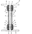
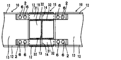
建築用構造体の施工においてH形鋼を接合する場合、従来より、図20に示すような接合構造が用いられている。この接合構造では、隣り合うH形鋼10、11の端部にかかる曲げモーメントが主にフランジ12断面に軸力となって伝達するため、隣り合うH形鋼10、11のフランジ12同士を軸力方向に軸力が伝達するように、フランジ12の表裏面に各々添え板8を当てて挟み込み、ボルト6とナット7で締付けて2面の摩擦面で摩擦接合している。
When joining H-section steels in the construction of building structures, a joining structure as shown in FIG. 20 has been conventionally used. In this joint structure, the bending moment applied to the ends of the adjacent H-
また、H形鋼10、11にかかる剪断力が主にウエッブ13断面に鉛直方向のせん断力となって伝達するため、隣り合うH形鋼10、11のウエッブ13に剪断力が伝達するように、ウエッブ13の両面に各々添え板9を当てて挟み込み、ボルト6とナット7で締付けて2面の摩擦面で摩擦接合している。さらに、H形鋼10、11にかかる軸力はフランジ12同士、ウエッブ13同士の両方の接合で伝達している。
Further, since the shearing force applied to the H-
このような従来の接合構造で、隣り合うH形鋼10、11の高い接合強度を保持させるためには、多数の添え板8、9と、各々の添え板8、9を固定するための多くのボルト6及びナット7が必要となる。そのため、使用する部品点数が非常に多くなりコストがかかるとともに、接合するのに多大な手間がかかるという問題があった。
In order to maintain the high joining strength of the adjacent H-
このような問題に対して、H形鋼のフランジの内側面とウエッブの側面に当接して接合するL形材を用い、ボルトにより接合する方法が提案されている(特許文献1を参照)。この提案によれば、接合強度を維持したまま添え板の枚数を減らすことができる。しかしながら、使用するボルトの数は従来と同程度であるためコストがかかり、施工性も従来と同様に低いものであった。 To solve such a problem, a method of joining with bolts using an L-shaped member that abuts and joins the inner side surface of the flange of the H-shaped steel and the side surface of the web has been proposed (see Patent Document 1). According to this proposal, the number of side plates can be reduced while maintaining the joint strength. However, since the number of bolts used is about the same as the conventional one, the cost is high and the workability is also low as in the conventional one.
一方、図20に示す隣り合うH形鋼10、11のフランジ12の表面と裏面を2枚の添え板で挟み込み、ボルト6とナット7により締付けて接合する従来の接合構造では、必然的にフランジ12の表面側にボルト6の頭やナット7、添え板8が突出する。ここで、このような接合構造において接合部のフランジ12表面側に、床など他部位の施工をする場合には、突出したボルト6の頭やナット7、添え板8が邪魔になり、これらを避けるための設計が必要となるため、フランジ12の表面側はフラットであることが望まれていた。
On the other hand, in the conventional joining structure in which the front surface and the back surface of the
このような問題に対して上記特許文献1では、フランジ裏側の添板とウエッブ添板の半分を一体化し、L型にしているが、フランジの添板として兼用しているので、フランジとのボルトの接合は必須になっており、フランジ外面へのボルト突起は解決されていない。 In response to such a problem, in Patent Document 1, half of the flange backside plate and the web plate are integrated to form an L shape, but since they are also used as the flange plate, bolts with the flange are bolted. Joining is mandatory, and bolt protrusions on the outer surface of the flange have not been resolved.
そこで、接合するH形鋼の端面にエンドプレートを溶接し、エンドプレート同士をボルトとナットで固定する提案がなされている(特許文献2を参照)。この提案によれば、部品点数を少なくし、作業性に優れ、フランジ表面にボルトの頭やナットの突出がない構造とすることができる。 Therefore, it has been proposed to weld end plates to the end faces of H-shaped steels to be joined and fix the end plates to each other with bolts and nuts (see Patent Document 2). According to this proposal, it is possible to reduce the number of parts, to have excellent workability, and to have a structure in which the head of the bolt and the nut do not protrude on the flange surface.
また、フランジ表面からの突起を無くすための他の方法として、上フランジの先端に、ボルト頭を沈める凹みを加工した厚い板材を完全溶け込み溶接で一体に形成し、現場でフランジの力を伝達する添板をフランジ内側に配置して貫通ボルトで接合する提案がなされている(特許文献3を参照)。 In addition, as another method for eliminating protrusions from the flange surface, a thick plate material with a recess that sinks the bolt head is integrally formed at the tip of the upper flange by complete penetration welding, and the force of the flange is transmitted on site. It has been proposed to arrange the splicing plate inside the flange and join it with a through bolt (see Patent Document 3).
しかしながら、上記特許文献2の提案の、H形鋼の端部に設けたエンドプレート同士をボルトで接合する方法では、ボルトの軸方向がエンドプレートの面外方向であるため、厚板にして変形を少なくしても微少な変形は避けられず、また高力ボルトの引張接合における微少変形も加わり、図20に示す従来の添板方式のような完全剛接合は困難であった。
However, in the method of joining the end plates provided at the ends of the H-shaped steel with bolts, which is proposed in
また、上記特許文献3の提案では、凹加工した厚い板材が高価であること、部品とH形鋼フランジの完全溶け込み溶接が高コストであること、また、添板との摩擦面が1面剪断摩擦接合であるため、従来の2面剪断摩擦接合にくらべてボルトの本数が2倍近く必要であること等の問題があった。
Further, in the proposal of
本発明は以上のような事情に鑑みてなされたものであり、従来のH形鋼の接合構造と同程度の接合強度を有するとともに、部品点数を少なくでき、接合施工が容易であり、さらに、フランジの表面側をフラットにすることが可能なH形鋼の接合構造を提供することを課題としている。 The present invention has been made in view of the above circumstances, has a joining strength equivalent to that of a conventional H-section steel joining structure, can reduce the number of parts, is easy to join, and further. An object of the present invention is to provide a joint structure of H-shaped steel capable of flattening the surface side of a flange.
本発明のH形鋼の接合構造は、上記の技術的課題を解決するためになされたものであって、以下のことを特徴としている。 The joint structure of the H-section steel of the present invention has been made in order to solve the above technical problems, and is characterized by the following.
第1に、本発明のH形鋼の接合構造は、H形鋼と隣り合う少なくともフランジとウエッブを有する鋼材の端部同士を接合するH形鋼の接合構造であって、前記H形鋼と前記鋼材の少なくともウエッブの片側で、かつ、該ウエッブの表面に対して平行に配設され、フランジの裏面に溶接された伝達プレートと、該伝達プレートに密着して設けられ、前記H形鋼と前記鋼材を繋ぐ連結プレートを備え、前記H形鋼と前記鋼材のウエッブ及び前記伝達プレートが、前記連結プレートを介してボルト接合されていることを特徴とする。 First, the joining structure of the H-shaped steel of the present invention is a joining structure of the H-shaped steel that joins the ends of the steel material having at least a flange and a web adjacent to the H-shaped steel, and is the same as the H-shaped steel. A transmission plate disposed on at least one side of the web of the steel material and parallel to the surface of the web and welded to the back surface of the flange, and a transmission plate provided in close contact with the transmission plate to form the H-beam. A connecting plate for connecting the steel materials is provided, and the H-shaped steel, the web of the steel materials, and the transmission plate are bolted to each other via the connecting plates.
第2に、本発明のH形鋼の接合構造は、H形鋼と隣り合う少なくともフランジとウエッブを有する鋼材の端部同士を接合するH形鋼の接合構造であって、前記H形鋼と前記鋼材の少なくともウエッブの片側で、かつ、該ウエッブの表面に対して平行に配設され、フランジの裏面に溶接された伝達プレートと、該伝達プレートが配設された側のウエッブとは反対側に、前記H形鋼と前記鋼材を繋ぐ連結プレートを備え、前記H形鋼と前記鋼材のウエッブ及び前記伝達プレートが、前記連結プレートを介してボルト接合されていることを特徴とする。 Secondly, the joining structure of the H-shaped steel of the present invention is a joining structure of the H-shaped steel that joins the ends of the steel material having at least a flange and a web adjacent to the H-shaped steel, and is the same as the H-shaped steel. A transmission plate arranged on at least one side of the steel material and parallel to the surface of the web and welded to the back surface of the flange, and a side opposite to the web on the side on which the transmission plate is arranged. A connecting plate for connecting the H-shaped steel and the steel material is provided, and the web of the H-shaped steel and the steel material and the transmission plate are bolted to each other via the connecting plate.
第3に、上記第1又は第2の発明のH形鋼の接合構造において、前記H形鋼と前記鋼材の前記伝達プレートが、前記ウエッブの表面に密着して配設されており、前記連結プレートが、前記伝達プレートの表面又は前記ウエッブの表面に密着して配設されていることが好ましい。 Thirdly, in the joint structure of the H-shaped steel of the first or second invention, the H-shaped steel and the transmission plate of the steel material are arranged in close contact with the surface of the web, and the connection is made. It is preferable that the plate is arranged in close contact with the surface of the transmission plate or the surface of the web.
第4に、上記第1又は第2の発明のH形鋼の接合構造において、前記H形鋼と前記鋼材の前記伝達プレートが、前記ウエッブの表面から前記連結プレートの厚み分の間隔を空けてフランジの裏面に溶接されて配設されており、前記連結プレートが、前記伝達プレートと前記ウエッブの間に密着して挟まれるように配設されていることが好ましい。 Fourth, in the joint structure of the H-shaped steel of the first or second invention, the H-shaped steel and the transmission plate of the steel material are spaced from the surface of the web by the thickness of the connecting plate. It is preferable that the connecting plate is welded to the back surface of the flange and is arranged so as to be closely sandwiched between the transmission plate and the web.
第5に、上記第1又は第2の発明のH形鋼の接合構造において、前記H形鋼と前記鋼材の前記伝達プレートが前記連結プレートの厚み分の間隔を空けて複数配設されており、前記連結プレートが、前記ウエッブと前記伝達プレートの間、及び/又は、前記複数の伝達プレートの間に密着して挟まれるように配設されていることが好ましい。 Fifth, in the joint structure of the H-shaped steel of the first or second invention, a plurality of the H-shaped steel and the transmission plate of the steel material are arranged at intervals corresponding to the thickness of the connecting plate. It is preferable that the connecting plate is arranged so as to be closely sandwiched between the web and the transmission plate and / or between the plurality of transmission plates.
第6に、上記第1又は第2の発明のH形鋼の接合構造において、前記H形鋼と前記鋼材の上下の前記伝達プレートと上下の前記連結プレートの間に、各々を繋ぐ剪断連結プレートが設けられていることが好ましい。 Sixth, in the joint structure of the H-shaped steel of the first or second invention, a shear connecting plate that connects the H-shaped steel and the upper and lower transmission plates of the steel material and the upper and lower connecting plates, respectively. Is preferably provided.
第7に、上記第1から第6の発明のH形鋼の接合構造において、前記鋼材が、H形鋼、溝形鋼、Z形鋼、I形鋼のいずれかであることが好ましい。 Seventh, in the joint structure of the H-section steels of the first to sixth inventions, it is preferable that the steel material is any one of H-section steel, channel steel, Z-section steel, and I-section steel.
第8に、本発明のH形鋼の接合構造は、H形鋼と構造物を接合するH形鋼の接合構造であって、前記H形鋼の少なくともウエッブの片側で、かつ、該ウエッブの表面に対して平行に配設され、フランジの裏面に溶接された伝達プレートと、該伝達プレートに密着して設けられ、前記H形鋼と前記構造物を繋ぐ連結プレートを備え、前記連結プレートの一部が前記構造物に溶接またはボルト接合されており、少なくとも一端部が前記H形鋼のウエッブ及び前記伝達プレートとボルト接合されていることを特徴とする。 Eighth, the joining structure of the H-shaped steel of the present invention is a joining structure of the H-shaped steel that joins the H-shaped steel and the structure, and is at least one side of the web of the H-shaped steel and of the web. The connecting plate is provided with a transmission plate arranged parallel to the front surface and welded to the back surface of the flange, and a connecting plate provided in close contact with the transmission plate to connect the H-shaped steel and the structure. A part thereof is welded or bolted to the structure, and at least one end thereof is bolted to the web of the H-section steel and the transmission plate.
第9に、本発明のH形鋼の接合構造は、H形鋼と構造物を接合するH形鋼の接合構造であって、前記H形鋼の少なくともウエッブの片側で、かつ、該ウエッブの表面に対して平行に配設され、フランジの裏面に溶接された伝達プレートと、該伝達プレートが配設された側のウエッブとは反対側に、前記H形鋼と前記構造物を繋ぐ連結プレートを備え、前記連結プレートの一部が前記構造物に溶接またはボルト接合されており、少なくとも一端部が前記H形鋼のウエッブ及び前記伝達プレートとボルト接合されていることを特徴とする。 Ninth, the joining structure of the H-shaped steel of the present invention is a joining structure of the H-shaped steel that joins the H-shaped steel and the structure, and is at least one side of the web of the H-shaped steel and of the web. A transmission plate arranged parallel to the front surface and welded to the back surface of the flange, and a connecting plate connecting the H-shaped steel and the structure on the opposite side of the web on the side where the transmission plate is arranged. A part of the connecting plate is welded or bolted to the structure, and at least one end thereof is bolted to the web of the H-section steel and the transmission plate.
第10に、上記第8又は第9の発明のH形鋼の接合構造において、前記H形鋼の前記伝達プレートが、前記ウエッブの表面に密着して配設されており、前記連結プレートが前記構造物に溶接され、少なくとも一端部が前記伝達プレートの表面又は前記ウエッブの表面に密着して配設されていることが好ましい。 Tenth, in the joint structure of the H-shaped steel of the eighth or ninth invention, the transmission plate of the H-shaped steel is arranged in close contact with the surface of the web, and the connecting plate is the connecting plate. It is preferable that the structure is welded and at least one end thereof is arranged in close contact with the surface of the transmission plate or the surface of the web.
第11に、上記第8又は第9の発明のH形鋼の接合構造において、前記H形鋼の前記伝達プレートが、前記ウエッブの表面から前記連結プレートの厚み分の間隔を空けてフランジの裏面に溶接されて配設されており、前記連結プレートが前記構造物に溶接され、少なくとも一端部が前記伝達プレートと前記ウエッブの間に密着して挟まれるように配設されていることが好ましい。 Eleventh, in the welded structure of the H-shaped steel of the eighth or ninth invention, the transmission plate of the H-shaped steel is spaced from the front surface of the web by the thickness of the connecting plate to the back surface of the flange. It is preferable that the connecting plate is welded to the structure and at least one end thereof is closely sandwiched between the transmission plate and the web.
第12に、上記第8又は第9の発明のH形鋼の接合構造において、前記H形鋼の前記伝達プレートが前記連結プレートの厚み分の間隔を空けて複数配設されており、前記連結プレートが前記構造物に溶接され、少なくとも一端部が前記ウエッブと前記伝達プレートの間、及び/又は、前記複数の伝達プレートの間に密着して挟まれるように配設されていることが好ましい。 Twelvely, in the joint structure of the H-shaped steel of the eighth or ninth invention, a plurality of the transmission plates of the H-shaped steel are arranged at intervals corresponding to the thickness of the connecting plate, and the connecting. It is preferable that the plate is welded to the structure and at least one end thereof is arranged so as to be closely sandwiched between the web and the transmission plate and / or between the plurality of transmission plates.
第13に、上記第8から第12の発明のH形鋼の接合構造において、前記構造物が、H形鋼、溝形鋼、Z形鋼、I形鋼、角形鋼管、基礎定着板のいずれかであることが好ましい。 Thirteenth, in the joint structure of H-section steels of the eighth to twelfth inventions, the structure is any of H-section steel, channel steel, Z-section steel, I-section steel, square steel pipe, and foundation fixing plate. Is preferable.
本発明のH形鋼の接合構造によれば、従来のH形鋼の接合構造と同程度の接合強度を有するとともに、部品点数を少なくでき、接合施工が容易であり、さらに、フランジの表面側をフラットにすることが可能となる。 According to the joining structure of the H-shaped steel of the present invention, the joining strength is about the same as that of the conventional H-shaped steel joining structure, the number of parts can be reduced, the joining work is easy, and the surface side of the flange. Can be flattened.
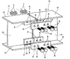
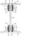
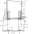
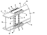
本発明のH形鋼の接合構造について図面に基づいて以下に詳述する。図1は、本発明のH形鋼の接合構造の一実施形態を示す分解斜視図であり、図2は図1の実施形態の接合後のA−A断面図である。 The joint structure of the H-section steel of the present invention will be described in detail below based on the drawings. FIG. 1 is an exploded perspective view showing an embodiment of an H-section steel joining structure of the present invention, and FIG. 2 is a cross-sectional view taken along the line AA after joining of the embodiment of FIG.
本実施形態のH形鋼の接合構造は、H形鋼10と隣り合う少なくともフランジ12とウエッブ13を有する鋼材11の端部同士を接合するH形鋼の接合構造であって、H形鋼10と鋼材11の少なくともウエッブ13の片側で、かつ、ウエッブ13の表面に対して平行に配設され、フランジ12の裏面に溶接された伝達プレート2と、該伝達プレート2に密着して設けられ、H形鋼10と鋼材11を繋ぐ連結プレート3を備えている。そして、H形鋼10と鋼材11のウエッブ13及び伝達プレート2が、連結プレート3を介してボルト接合されている。
<第1実施形態>
図1及び図2に示す第1実施形態のH形鋼の接合構造では、H形鋼10と、隣り合う鋼材としてのH形鋼11とを接合する状態を示しており、伝達プレート2がフランジ12の裏面に長手方向に沿って溶接されるとともに、ウエッブ13の表面に密着するように設けられている。The joining structure of the H-shaped steel of the present embodiment is a joining structure of the H-shaped steel that joins the ends of the
<First Embodiment>
The joining structure of the H-shaped steel of the first embodiment shown in FIGS. 1 and 2 shows a state in which the H-shaped
H形鋼10は、上下のフランジ12と、各フランジ12の断面中央部を垂直に繋ぐ1本のウエッブ13から構成されている。また、接合する隣り合うH形鋼11は、各々がほぼ同じ断面のH形状を有している。なお、本発明における隣り合うH形鋼11は、H形鋼10と異なった断面形状でもよい。また、各々が長尺のH形鋼や、片方が柱状の鋼材から水平又は所定の角度をもって接合されている短尺のH形鋼でもよい。このようなH形鋼の接合は、例えば梁や柱、また、筋交い等の直線的な接合に用いることができる。
The H-
伝達プレート2の断面形状は、フランジ12とウエッブ13の接合部の断面形状に密着する形状となっており、例えば、フランジ12とウエッブ13の接合部が断面円弧形状に形成されている場合には、伝達プレート2の対応縁部の形状もこれに密着する断面円弧形状又は面取り形状に形成されている。
The cross-sectional shape of the
伝達プレート2とフランジ12の溶接は、伝達プレート2の縁部とフランジ12の相互に力が伝わるように溶接されている。なお、片方の伝達プレートとフランジの溶接強度は、フランジ12断面の許容強度からウエッブ13からの伝達強度を差し引いた値の1/2以上の強度となるように溶接するのが好ましい。
The
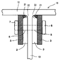
また、第1実施形態では、伝達プレート2の表面に連結プレート3を密着して設ける構成であるため、伝達プレート2とフランジ12の溶接部21が伝達プレート2の縁に沿って盛り上がる所謂ビードが突出しないように溶接されていることが望ましい。このような溶接状態とするために、例えば、図3に示すように、予め伝達プレート2の溶接部21の縁に面取り部22を形成させておくことができる。溶接は、通常、面取部22内を埋めるように部分溶け込み溶接するが、余盛り部分はカットすることで伝達プレート2と連結プレート3を密着して設けることが可能となる。また、密着させる連結プレート3の縁に面取り部を形成してビードの盛り上がりとの接触を逃がすこともできる。フランジ12と伝達プレート2の溶接部21の溶接形態は特に限定されるものではないが、上記のことを考慮した場合、部分溶け込み溶接で余盛りカットが望ましい。
Further, in the first embodiment, since the connecting
また、隣り合うH形鋼10、11との接合における、各々の伝達プレート2の配設対応箇所に、同じ幅の伝達プレート2を配設する。具体的には、ウエッブ13を挟んだ両側で、上下のフランジ12の裏側の合計4カ所に配設することができる。また、伝達プレート2は、フランジ12の裏側と伝達プレート2の上記溶接強度が十分に得られる厚さと溶接長さが必要である。溶接長さは、ボルト6の本数と間隔で決るが、伝達プレート2の厚さが薄い方がボルト6の長さが短くなり経済的であるため、ボルト6の間隔を広げるなどして溶接長さを大きくとることが好ましい。
Further, in the joint with the adjacent H-shaped
連結プレート3は、隣り合うH形鋼10、11の対応する伝達プレート2を介してウエッブ13同士を繋ぐ部材である。伝達プレート2を介してのウエッブ13の接合は、ボルト6等による摩擦接合により行われる。具体的には、伝達プレート2と連結プレート3が重なり合う部分の所定の位置に、連結プレート3、伝達プレート2及びウエッブ13を同軸に貫通する貫通孔5を設け、その貫通孔5にボルト6を挿通してナット7で締め付けて摩擦接合する。このとき、連結プレート3の強度とボルト接合の強度は、H形鋼の許容曲げモーメントをボルト軸間距離で除した大きさの1/2、又はH形鋼の許容軸力の1/4のいずれか大きい方の強度が必要になる。
The connecting
ボルト6は、必要な強度に応じて高力ボルトの太さと強度及び本数を決める。このとき、ボルト6のピッチや本数を変えることで伝達プレート2の長さと厚さを設計することができる。また、伝達プレート2が長い方がウエッブ13とフランジ12の接合部から伝達される強度が大きくなるとともにフランジ12との溶接長が多くとれるので溶接サイズが小さく伝達プレート2を薄くすることができ、ボルト6の長さを短くすることができるため経済的である。
For the
連結プレート3は、必要な強度に応じて材料強度と断面積を決定する。このとき、連結プレート3の厚さが薄い方がボルト6の長さを短くすることができるため経済的であるが、必要な断面積を得るために幅が広くなりボルト軸芯からのズレに注意が必要である。このとき、ボルト6の列をウエッブ13方向に複数列にすることでボルト6の軸間距離が短くなり必要強度が増加する。また、伝達プレート2も短くなるが、連結プレート3の幅を広くすることができる。また、連結プレート3の伝達プレート2との接合面は、摩擦接合の強度を大きくする観点から、赤錆処理又はブラスト処理を施しておくことが望ましい。
The connecting
いずれも設計における選択肢であるが、接合するH形鋼10、11の大きさに応じて、適切な設計するのが望ましい。図1に示す第1実施形態では、伝達プレート1枚に付き2本のボルト6が用いられている。
Both are design options, but it is desirable to design appropriately according to the size of the H-section steels 10 and 11 to be joined. In the first embodiment shown in FIG. 1, two
また、摩擦接合においては一般的に摩擦面が多いほど接合強度は大きくなる。例えば建築基準において高力ボルトの1面剪断摩擦接合に対して2面剪断摩擦接合は2倍の強度が与えられている。第1実施形態のH形鋼の接合構造では、伝達プレート2と連結プレート3の1摩擦面をウエッブ13の両側から一つの高力ボルトで接合するので、H形鋼10とH形鋼11の高力ボルト接合は2面剪断摩擦接合になる。
Further, in friction stir welding, generally, the larger the friction surface, the higher the bonding strength. For example, according to building standards, two-sided shear friction welding is twice as strong as one-sided shear friction welding of high-strength bolts. In the joining structure of the H-shaped steel of the first embodiment, since one friction surface of the
ウエッブ13を挟んだ両側かつ上下のフランジ12の裏面4カ所に溶接した伝達プレート2に伝わった力は、溶接21からフランジ12に伝わるが、伝達プレート2とウエッブ13は高力ボルト6で共締めしているので伝達プレート2に伝わった力はウエッブ13にも伝達されて、ウエッブ13とフランジ12の接合部からフランジ12に力が伝わる。
The force transmitted to the
H形鋼10とH形鋼11の接合により、連結プレート3から伝達プレート2に伝わった力は、ウエッブ13と伝達プレート2の溶接部21を経由してフランジ12に伝わる。よって、フランジ12の裏側とウエッブ13で囲まれたエリア内のみで、H形鋼10、11にかかる曲げモーメント、軸力、剪断力を伝達できる接合とすることができ、少ない部品点数で従来と同程度の強度を有する接合が可能となる。これは、伝達プレート2とフランジ12との溶接21による接合と、ウエッブ13、伝達プレート2及び連結プレート3を高力ボルト6で共締めする総合的な結合力によるものである。
The force transmitted from the connecting
また、第1実施形態のH形鋼の接合機構では、フランジ12の裏面に伝達プレート2を溶接しているため、ボルト6による突起や添え板等による段差のないフラットな面とすることができ、フランジ12の表面側への施工性を向上させることができる。
<第2実施形態>
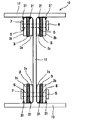
本発明においては、図4、図5に示すような第2実施形態のH形鋼の接合構造とすることもできる。第2実施形態では、伝達プレート2がウエッブ13の表面から連結プレート3の厚み分の間隔を空けてフランジ12の裏面に溶接されて設けられ、連結プレート3が伝達プレート2とウエッブ13の間に密着して設けられている。即ち、連結プレート3は伝達プレート2とウエッブ13で挟まれる構成となっている。Further, in the joining mechanism of the H-shaped steel of the first embodiment, since the
<Second Embodiment>
In the present invention, the H-shaped steel joint structure of the second embodiment as shown in FIGS. 4 and 5 can also be used. In the second embodiment, the
伝達プレート2の溶接は、ウエッブ13とフランジ12の接合部から伝達される強度の1/2以上の強度で溶接されていればよく、連結プレート3と溶接余盛りの干渉を避けるために、フランジ12の裏面と伝達プレート2を外側から隅肉溶接が望ましいが、必要に応じて外側から部分溶け込み溶接にしてもよい。
The
また、ウエッブ13と密着して設けられる連結プレート3の断面形状は、フランジ12とウエッブ13の接合部の断面形状に密着する形状となっており、例えば、フランジ12とウエッブ13の接合部が断面円弧形状に形成されている場合には、連結プレート3の対応当接部の形状もこれに密着する断面円弧状に形成又は面取されている。
Further, the cross-sectional shape of the connecting
第2実施形態によれば、ウエッブ13の両側で、各々2面の摩擦面になり、この連結プレート2枚をウエッブ13の両側から高力ボルト6及びナット7で一緒にボルト接合するので、H形鋼10とH形鋼11を結ぶ連結プレート3は、高力ボルト6による4面剪断摩擦接合になる。そのため第1実施形態の2面剪断摩擦接合に比べてボルト6の本数を半減させることができる。
<第3−1実施形態>
更に本発明においては、伝達プレート2が連結プレート3の厚み分の間隔を空けて複数設け、連結プレート3をウエッブ13と伝達プレート2の間及び/又は複数の伝達プレート2の間に密着して挟むように設けることができる。According to the second embodiment, there are two friction surfaces on both sides of the
<Third 3-1 Embodiment>
Further, in the present invention, a plurality of
具体的には、例えば、図6に示すような第3−1実施形態のH形鋼の接合構造構成とすることができる。この第3−1実施形態のH形鋼の接合構造では、ウエッブ13と伝達プレート2aを第1実施形態と同様に密着して設け、その外側に連結プレート3の厚み分の間隔を空けて更に伝達プレート2bを設けている。なお、伝達プレート2a、2bは各々フランジ12の裏側に溶接部21で溶接されている。そして、ウエッブ13に密着した伝達プレート2aと外側に間隔を空けて設けた伝達プレート2bの間に連結プレート3を密着して挟むように設けている。
Specifically, for example, the joint structure of the H-section steel of the third embodiment as shown in FIG. 6 can be used. In the joint structure of the H-shaped steel of the 3-1 embodiment, the
第3−1実施形態の構成では、ウエッブ13の片側において、伝達プレート2aと連結プレート3の摩擦面及び連結プレート3と伝達プレート2bの摩擦面の2面の摩擦面となり、ウエッブ13の両側では合計4面の摩擦面による4面剪断摩擦接合で連結される。これにより、第1実施形態の2面剪断摩擦接合に比べてボルト6の本数を半減させることができる。
<第3−2実施形態>
また、第3−2実施形態として、図7に示すように、伝達プレート2aを第2実施形態と同様にウエッブ13の表面から連結プレート3aの厚み分の間隔を空けてフランジ12の裏面に溶接して設け、更に、その外側に連結プレート3bの厚み分の間隔を空けて伝達プレート2bを設け、連結プレート3aを伝達プレート2aとウエッブ13の間に密着して設けるとともに、伝達プレート2aと2枚目の伝達プレート2bの間にさらに連結プレート3bを設ける構成とすることもできる。この構成によれば、ウエッブ13の両側で4枚の連結プレート3が接合され、合計8面の摩擦面により8面剪断摩擦接合されるため、より強力に接合することができる。
<第4実施形態>
本発明において、連結プレート3の断面だけで剪断力を伝達できない場合や、更に高い剪断力の伝達の要請があるような場合には、図8、図9に示すように、上下の連結プレート3の間又は連結プレートの外に各々を繋ぐ剪断連結プレート4を挟んで設けることができる。これにより、大きい剪断力を伝達することが可能となる。In the configuration of the third 3-1 embodiment, on one side of the
<Third 3-2 Embodiment>
Further, as the 3-2nd embodiment, as shown in FIG. 7, the
<Fourth Embodiment>
In the present invention, when the shearing force cannot be transmitted only by the cross section of the connecting
本発明のH形鋼の接合構造では、上記第1実施形態から第4実施形態に代表される、H形鋼の端部と他の部材の端部同士を接合する構成のほか、H形鋼の端部と他の構造物の端部以外の部位とを接合する構成とすることもできる。
<第5実施形態>
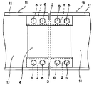
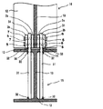
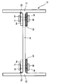
図10は第5実施形態の分解斜視図を示しており、図11は、図10の接合後のB−B断面図を示している。第5実施形態では、水平に配設された構造物としての梁状のH形鋼15のフランジ12に、垂直に柱状のH形鋼10を接合する状態を示している。垂直に配設するH形鋼10の端部には、第1実施形態と同様に伝達プレート2がフランジ12の裏面に長手方向に沿って溶接され、ウエッブ13の表面に密着するように設けられている。伝達プレート2のフランジ12の裏面への溶接は第1実施形態と同様の構成で行うことができる。In the joining structure of the H-shaped steel of the present invention, in addition to the configuration of joining the ends of the H-shaped steel and the ends of other members represented by the first to fourth embodiments, the H-shaped steel It is also possible to form a structure in which the end portion of the steel is joined to a portion other than the end portion of another structure.
<Fifth Embodiment>
FIG. 10 shows an exploded perspective view of the fifth embodiment, and FIG. 11 shows a cross-sectional view taken along the line BB after joining of FIG. In the fifth embodiment, a state in which the columnar H-shaped
また、水平に配設されたH形鋼15には、予め、長手方向に対して垂直に、フランジ12から突出するように連結プレート31が設けられている。具体的には、上側のフランジ12のウエッブ13を隔てた両側に設けた挿通孔14に連結プレート31を挿通して、一端部を下側のフランジ12の裏側の溶接部32に溶接して固定している。なお、本実施形態では、上側のフランジ12と連結プレート31も溶接されている。
Further, the horizontally arranged H-shaped
水平に配設されるH形鋼15に溶接された連結プレート31と、垂直に配設されるH形鋼10の伝達プレート2は、各々を密着して嵌合させた状態で接合される。即ち、水平に配設されるH形鋼15に溶接された連結プレート31のウエッブ13を隔てた間隔は、垂直に配設されるH形鋼10のウエッブ13と伝達プレート2枚分の合計の厚みとなっており、嵌合させた状態で連結プレート31と伝達プレート2の表面が密着する間隔となっている。
The connecting
また、連結プレート31の溶接されていない他端部に、垂直に配設されるH形鋼10を嵌合させた状態において、伝達プレート2と連結プレート31が重なり合う部分の所定の位置に、連結プレート31、伝達プレート2及びウエッブ13を同軸に貫通する貫通孔5を設け、その貫通孔5にボルト6を挿通してナット7で締め付けて摩擦接合する。なお、ボルト接合の条件等についても第1実施形態と同様の条件で決定することができる。これにより、水平に配設されるH形鋼15と、垂直に配設されるH形鋼10を従来の接合構造と同程度の接合強度で接合できるとともに、部品点数を少なくでき、接合施工が容易であり、各々のフランジ12の表面側をフラットにすることが可能となる。
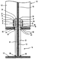
<第6実施形態>
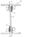
本発明においては、図12、図13に示すような第6実施形態のH形鋼の接合構造とすることもできる。第6実施形態では、垂直に配設するH形鋼10の端部には第2実施形態と同様に伝達プレート2がウエッブ13の表面から連結プレート31の厚み分の間隔を空けてフランジ12の裏面に溶接されて設けられ、連結プレート31の端部が伝達プレート2とウエッブ13の間に密着して設けられている。即ち、連結プレート3は伝達プレート2とウエッブ13で挟まれて、これをボルト接合した構成となっている。また、連結プレート31は、水平に配設されるH形鋼15の上側のフランジ12に設けた挿通孔14に挿通してウエッブ13に密着して設けられ、さらに上下のフランジ12に溶接されている。Further, in a state where the H-shaped
<Sixth Embodiment>
In the present invention, the H-shaped steel joint structure of the sixth embodiment as shown in FIGS. 12 and 13 can also be used. In the sixth embodiment, as in the second embodiment, the
第6実施形態によれば、垂直に配設されるH形鋼10の端部において、第2実施形態と同様に、ウエッブ13の片側では、連結プレート31と伝達プレート2の接触面が2面の摩擦面、ウエッブ13の両側で合計4面の摩擦面になり、この連結プレート2枚をウエッブ13の両側から高力ボルト6及びナット7で一緒にボルト接合するのでH形鋼10と連結プレート31は、高力ボルトによる4面剪断摩擦接合になる。そのため第5実施形態の2面剪断接合に比べてボルト6の本数を半減させることができる。
<第7−1実施形態>
更に本発明においては、第7−1実施形態として、垂直に配設されるH形鋼の端部において、第3−1実施形態と同様に、伝達プレート2が連結プレート3の厚み分の間隔を空けて複数設けられており、連結プレート3が、ウエッブ13と伝達プレート2の間及び/又は複数の伝達プレート2の間に密着して挟まれるように設けることができる。According to the sixth embodiment, at the end of the vertically arranged H-shaped
<Section 7-1 Embodiment>
Further, in the present invention, as the 7-1th embodiment, at the end of the vertically arranged H-shaped steel, the
具体的には、例えば、図14に示すようなH形鋼の接合構造構成とすることができる。この第7−1実施形態のH形鋼の接合構造では、ウエッブ13と伝達プレート2aを第3−1実施形態と同様に密着して設け、その外側に連結プレート31の厚み分の間隔を空けて更に伝達プレート2bを設けている。そして、ウエッブ13に密着した伝達プレート2aと外側に間隔を空けて設けた伝達プレート2bの間に連結プレート31を密着して挟み込み、これをボルト接合した構成となっている。また、連結プレート31は、垂直に配設されるH形鋼10のウエッブ13と伝達プレート2a2枚分の合計の厚みの間隔を隔てて、水平に配設されるH形鋼の上側のフランジ12に設けた挿通孔14に挿通して、上下のフランジ12に溶接されている。
Specifically, for example, the joint structure of H-shaped steel as shown in FIG. 14 can be used. In the joint structure of the H-shaped steel of the 7-1 embodiment, the
第7−1実施形態の構成では、ウエッブ13の片側において、伝達プレート2aと連結プレート31の摩擦面、更に連結プレート31と伝達プレート2bの摩擦面の合計2面の摩擦面になり、この連結プレート2枚をウエッブ13の両側から高力ボルト6及びナット7で一緒にボルト接合するのでH形鋼10と連結プレート31は、高力ボルトによる4面剪断摩擦接合になる。そのため第6実施形態と同様に、第5実施形態の2面剪断摩擦接合に比べてボルト6の本数を半減させることができる。
<第7−2実施形態>
また、図示しない他の第7−2実施形態として、第3−2実施形態と同様に、伝達プレート2をウエッブ13の表面から連結プレート31の厚み分の間隔を空けてフランジ12の裏面に溶接して設け、更に、その外側に連結プレート31の厚み分の間隔を空けて伝達プレート2を設け、連結プレート31を伝達プレート2とウエッブ13の間に密着して設けるとともに、2枚の伝達プレート2の間にさらに連結プレート31を設ける構成とすることもできる。この構成によれば、ウエッブ13の両側で4枚の連結プレート31が接合され、合計8面の摩擦面により8面剪断摩擦接合されるため、より強力に接合することができる。なお、水平に配設されるH形鋼15に対する連結プレート31の溶接位置は、上記の状態となる位置である。
<第8実施形態>
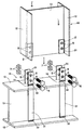
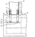
また、第8実施形態として図15に示すように、基礎16の構造物の柱脚アンカーとしての基礎定着板18に、連結プレート31を垂直方向に向けて溶接し、これを鉄筋17などで囲み、コンクリートで強固に一体にすることもできる。そして、基礎16から突出させた連結プレート31の端を垂直に配設されたH形鋼10のウエッブ13及び連結プレート2を合わせてボルト結合する。なお、この際、H形鋼10の伝達プレート2及び基礎16に埋込まれた構造物である基礎定着板18に溶接された連結プレート31の配置構成は、設計等に応じて上記第5実施形態〜第7実施形態のいずれの構成とすることもできる。<第9実施形態>
さらに、第9実施形態として、図16に示すように、水平に配設したH形鋼15において、連結プレート31を上下のフランジ12に設けた挿通孔14に挿通させて溶接し、水平に配設したH形鋼15に対し垂直に配設したH形鋼10で上下から挟むように接合することもできる。なお、この構成においても、H形鋼10の伝達プレート2及びH形鋼15に溶接された連結プレート31の配置構成は、設計等に応じて上記第5実施例〜第7実施例の何れの構成とすることができる。
<第10実施形態>
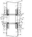
さらに第10実施形態として、図17に示すように、水平に配設したH形鋼15のウエッブ13に対して垂直方向にスチフナ19を設けるとともに、ウエッブ13に挿通させた連結プレート31をスチフナ19に溶接又はボルト接合し、水平に配設したH形鋼15に対し水平、直角に配設したH形鋼10、11で左右から挟むようにボルト接合することもできる。In the configuration of the 7-1th embodiment, on one side of the
<7-2nd Embodiment>
Further, as another 7-2 embodiment (not shown), the
<8th Embodiment>
Further, as shown in FIG. 15 as the eighth embodiment, the connecting
Further, as a ninth embodiment, as shown in FIG. 16, in the horizontally arranged H-shaped
<10th Embodiment>
Further, as a tenth embodiment, as shown in FIG. 17, a
これにより、H形鋼10、11にかかる剪断力がH形鋼15に伝達されるとともに、連結プレート31により軸力と曲げモーメントが対抗するH形鋼10、11相互に伝達される。なお、この構成においてもH形鋼10、11の伝達プレート2及びH形鋼15のスチフナに溶接された連結プレート31の配置構成は、設計等に応じて上記第5実施形態〜第7実施形態のいずれの構成とすることもできる。
As a result, the shearing force applied to the H-shaped
また、本発明のH形鋼の接合構造においては、他の実施形態として、H形鋼10と隣り合う少なくともフランジ12とウエッブ13を有する鋼材11の端部同士を接合するH形鋼の接合構造であって、H形鋼10と鋼材11の少なくともウエッブ13の片側で、かつ、ウエッブ13の表面に対して平行に配設され、フランジ12の裏面に溶接された伝達プレート2と、該伝達プレート2が配設された側のウエッブ13とは反対側に、H形鋼10鋼材11を繋ぐ連結プレート3を備えており、H形鋼10と鋼材11のウエッブ13及び伝達プレート2が、連結プレート3を介してボルト接合されている構成とすることができる。上記の構成の一実施形態として、図18に第11実施形態のH形鋼の接合構造を示す。
<第11実施形態>
図18に示す第11実施形態のH形鋼の接合構造では、伝達プレート2がフランジ12の裏面に長手方向に沿って溶接されるとともに、ウエッブ13の表面に密着するように設けられている。そして、伝達プレート2が配設されたウエッブ13の反対側に、連結プレート3がウエッブ13の表面に密着するように設けられている。Further, in the joining structure of the H-shaped steel of the present invention, as another embodiment, the joining structure of the H-shaped steel that joins the ends of the
<11th Embodiment>
In the joint structure of the H-shaped steel of the eleventh embodiment shown in FIG. 18, the
第11実施形態によれば、伝達プレート2、ウエッブ13及び連結プレート3が高力ボルト6及びナット7で一緒にボルト接合されており、ウエッブ13の片側において、連結プレート3とウエッブ13の片面の一面剪断摩擦接合となっているので、連結プレート3とH形鋼10の芯ズレが最も小さいシンプルで低コストの接合構造とすることができる。
<第12実施形態>
さらに、図19に示す第12実施形態のH形鋼の接合構造では、図18に示す連結プレート3とウエッブ13の片面の一面剪断摩擦接合において、フランジ12に溶接される伝達プレート2及び連結プレート3の配設位置を上下でウエッブの13の反対側に設けている。第12実施形態によれば、連結プレート3とウエッブ13の片面の一面剪断摩擦接合が上下でバランスがとれ、芯ずれ(応力の中心のずれ)を解消することが可能となる。According to the eleventh embodiment, the
<12th Embodiment>
Further, in the joining structure of the H-section steel of the twelfth embodiment shown in FIG. 19, the
以上、本発明のH形鋼の継手構造について実施形態に基づいて説明したが、本発明は上記の実施形態に何ら限定されるものではなく、その要旨を逸脱しない範囲内において各種の変更が可能である。 The joint structure of the H-section steel of the present invention has been described above based on the embodiment, but the present invention is not limited to the above embodiment, and various modifications can be made without departing from the gist thereof. Is.
例えば、上記実施形態ではボルト6とナット7により摩擦接合しているが、リベットやボルトなどの締結具により剪断接合にすることもできる。また、ボルト6は通常高力ボルトが用いられるが、超高力ボルトを用いることができ、これによりボルト6の本数を減らすことができる。さらに、摩擦接合の強度を大きくする観点から、伝達プレート2又はウエッブ13と連結プレート3、13の密着する面には赤錆処理又はブラスト処理を施しておくこともできる。
For example, in the above embodiment, the
また、フランジ12とウエッブ13の接合部が断面円弧形状に形成されている場合に、これと密着する伝達プレート2や連結プレート3、31の対応縁部の形状も断面円弧形状又は面取り形状に形成したが、フランジ12とウエッブ13の接合部の円弧形状を避ける厚さの座金をウエッブ13に当てて干渉を避けることもできる。
Further, when the joint portion between the
また、第4実施形態では、剪断連結プレート4をウエッブ13の片側に1枚、両側で2枚設けているが、片側に複数枚設けることもできる。また、上下の連結プレート3と剪断プレート4を一体にしてもよい。
Further, in the fourth embodiment, one
また、上記第1実施形態〜第4実施形態では、H形鋼10と隣り合う鋼材としてH形鋼11を用い、上記第5実施形態〜第7実施形態、第9実施形態では、構造物として水平に配設したH形鋼15を用いているが、これらはH形鋼に限定されるものではなく、H形鋼、溝形鋼、Z形鋼、I形鋼、角形鋼管であってもよい。また、H形鋼10を溝形鋼、Z形鋼、I形鋼としてもよい。
Further, in the first to fourth embodiments, the H-shaped
さらに、第1実施形態〜第4実施形態では、H形鋼10と隣り合うH形鋼11を水平の梁として接合したが、各々を垂直の柱として接合してもよい。また、上記第5実施形態〜第9実施形態では、伝達プレート2を設けたH形鋼10を垂直に配設する構成としたが、伝達プレート2を設けたH形鋼10を水平に配設する構成とすることもできる。
Further, in the first to fourth embodiments, the H-shaped
さらにまた、上記第1実施形態〜第3−2実施形態、第5実施形態〜第10実施形態では、ウエッブ13の両側に伝達プレート2及び連結プレート3(31)を対称に設ける構成、第4実施形態では、ウエッブ13の両側に伝達プレート2及び剪断連結プレート4を対称に設ける構成としているが、本発明では、第1実施形態〜第10実施形態の何れの構成においても、ウエッブ13の片側のみに伝達プレート2及び連結プレート3、31(剪断連結プレート4)を設ける構成とすることもできる。
Furthermore, in the first to third to third embodiments and the fifth to tenth embodiments, the
さらにまた、第1実施形態〜第10実施形態の何れかの構成において、ウエッブ13の片側のみに伝達プレート2及び連結プレート3、31(剪断連結プレート4)を設け、それらを設けたウエッブ13とは反対側の面に、別途連結プレート3のみを設ける構成とすることもできる。
Furthermore, in any of the configurations of the first embodiment to the tenth embodiment, the
上記の構成を有する本発明のH形鋼の継手構造によれば、従来のH形鋼の継手構造と同様の接合強度を有するとともに、部品点数を少なくでき、接合施工が容易であり、さらに、フランジ表面をフラットにすることが可能となる。 According to the joint structure of the H-shaped steel of the present invention having the above configuration, the joint structure has the same strength as that of the conventional H-shaped steel joint structure, the number of parts can be reduced, the joining work is easy, and further. The flange surface can be flattened.
Claims (13)
前記H形鋼と前記鋼材の少なくともウエッブの片側で、かつ、該ウエッブの表面に対して平行に配設され、フランジの裏面に溶接された伝達プレートと、
該伝達プレートに密着して設けられ、前記H形鋼と前記鋼材を繋ぐ連結プレートを備え、
前記H形鋼と前記鋼材のウエッブ及び前記伝達プレートが、前記連結プレートを介してボルト接合されていることを特徴とするH形鋼の接合構造。It is a joining structure of H-shaped steel that joins the ends of steel materials having at least a flange and a web adjacent to the H-shaped steel.
A transmission plate arranged on at least one side of the H-section steel and the steel material and parallel to the surface of the web and welded to the back surface of the flange.
A connecting plate provided in close contact with the transmission plate and connecting the H-shaped steel and the steel material is provided.
A joining structure of H-shaped steel, wherein the web of the H-shaped steel, the web of the steel material, and the transmission plate are bolted to each other via the connecting plate.
前記H形鋼と前記鋼材の少なくともウエッブの片側で、かつ、該ウエッブの表面に対して平行に配設され、フランジの裏面に溶接された伝達プレートと、
該伝達プレートが配設された側のウエッブとは反対側に、前記H形鋼と前記鋼材を繋ぐ連結プレートを備え、
前記H形鋼と前記鋼材のウエッブ及び前記伝達プレートが、前記連結プレートを介してボルト接合されていることを特徴とするH形鋼の接合構造。It is a joining structure of H-shaped steel that joins the ends of steel materials having at least a flange and a web adjacent to the H-shaped steel.
A transmission plate arranged on at least one side of the H-section steel and the steel material and parallel to the surface of the web and welded to the back surface of the flange.
A connecting plate for connecting the H-shaped steel and the steel material is provided on the side opposite to the web on the side where the transmission plate is arranged.
A joining structure of H-shaped steel, wherein the web of the H-shaped steel, the web of the steel material, and the transmission plate are bolted to each other via the connecting plate.
前記連結プレートが、前記伝達プレートと前記ウエッブの間に密着して挟まれるように配設されていることを特徴とする請求項1又は2に記載のH形鋼の接合構造。The H-shaped steel and the transmission plate of the steel material are welded to the back surface of the flange at intervals of the thickness of the connecting plate from the surface surface of the web.
The H-section steel joint structure according to claim 1 or 2, wherein the connecting plate is arranged so as to be closely sandwiched between the transmission plate and the web.
前記連結プレートが、前記ウエッブと前記伝達プレートの間、及び/又は、前記複数の伝達プレートの間に密着して挟まれるように配設されていることを特徴とする請求項1又は2に記載のH形鋼の接合構造。A plurality of the H-shaped steel and the transmission plate of the steel material are arranged at intervals corresponding to the thickness of the connecting plate.
The first or second claim, wherein the connecting plate is arranged so as to be closely sandwiched between the web and the transmission plate and / or between the plurality of transmission plates. H-shaped steel joint structure.
前記H形鋼の少なくともウエッブの片側で、かつ、該ウエッブの表面に対して平行に配設され、フランジの裏面に溶接された伝達プレートと、
該伝達プレートに密着して設けられ、前記H形鋼と前記構造物を繋ぐ連結プレートを備え、
前記連結プレートの一部が前記構造物に溶接またはボルト接合されており、少なくとも一端部が前記H形鋼のウエッブ及び前記伝達プレートとボルト接合されていることを特徴とするH形鋼の接合構造。It is a joint structure of H-shaped steel that joins the H-shaped steel and the structure.
A transmission plate arranged on at least one side of the web of the H-section steel and parallel to the surface of the web and welded to the back surface of the flange.
A connecting plate provided in close contact with the transmission plate and connecting the H-section steel and the structure is provided.
A bonded structure of H-shaped steel, characterized in that a part of the connecting plate is welded or bolted to the structure, and at least one end thereof is bolted to the web of the H-shaped steel and the transmission plate. ..
前記H形鋼の少なくともウエッブの片側で、かつ、該ウエッブの表面に対して平行に配設され、フランジの裏面に溶接された伝達プレートと、
該伝達プレートが配設された側のウエッブとは反対側に、前記H形鋼と前記構造物を繋ぐ連結プレートを備え、
前記連結プレートの一部が前記構造物に溶接またはボルト接合されており、少なくとも一端部が前記H形鋼のウエッブ及び前記伝達プレートとボルト接合されていることを特徴とするH形鋼の接合構造。It is a joint structure of H-shaped steel that joins the H-shaped steel and the structure.
A transmission plate arranged on at least one side of the web of the H-section steel and parallel to the surface of the web and welded to the back surface of the flange.
A connecting plate for connecting the H-section steel and the structure is provided on the side opposite to the web on the side where the transmission plate is arranged.
A bonded structure of H-shaped steel, characterized in that a part of the connecting plate is welded or bolted to the structure, and at least one end thereof is bolted to the web of the H-shaped steel and the transmission plate. ..
前記連結プレートが前記構造物に溶接され、少なくとも一端部が前記伝達プレートの表面又は前記ウエッブの表面に密着して配設されていることを特徴とする請求項8又は9に記載のH形鋼の接合構造。The transmission plate of the H-shaped steel is arranged in close contact with the surface of the web.
The H-section steel according to claim 8 or 9, wherein the connecting plate is welded to the structure and at least one end thereof is arranged in close contact with the surface of the transmission plate or the surface of the web. Joint structure.
前記連結プレートが前記構造物に溶接され、少なくとも一端部が前記伝達プレートと前記ウエッブの間に密着して挟まれるように配設されていることを特徴とする請求項8又は9に記載のH形鋼の接合構造。The transmission plate of the H-shaped steel is welded to the back surface of the flange at a distance corresponding to the thickness of the connecting plate from the surface surface of the web.
The H according to claim 8 or 9, wherein the connecting plate is welded to the structure and at least one end thereof is arranged so as to be closely sandwiched between the transmission plate and the web. Joint structure of shaped steel.
前記連結プレートが前記構造物に溶接され、少なくとも一端部が前記ウエッブと前記伝達プレートの間、及び/又は、前記複数の伝達プレートの間に密着して挟まれるように配設されていることを特徴とする請求項8又は9に記載のH形鋼の接合構造。A plurality of the transmission plates of the H-shaped steel are arranged at intervals corresponding to the thickness of the connecting plate.
The connecting plate is welded to the structure, and at least one end thereof is arranged so as to be closely sandwiched between the web and the transmission plate and / or between the plurality of transmission plates. The H-section steel welded structure according to claim 8 or 9.
Applications Claiming Priority (3)
| Application Number | Priority Date | Filing Date | Title |
|---|---|---|---|
| JP2017199349 | 2017-10-13 | ||
| JP2017199349 | 2017-10-13 | ||
| PCT/JP2018/037911 WO2019074050A1 (en) | 2017-10-13 | 2018-10-11 | Joint structure for h-beam |
Publications (2)
| Publication Number | Publication Date |
|---|---|
| JPWO2019074050A1 JPWO2019074050A1 (en) | 2020-12-10 |
| JP6861425B2 true JP6861425B2 (en) | 2021-04-21 |
Family
ID=66100749
Family Applications (1)
| Application Number | Title | Priority Date | Filing Date |
|---|---|---|---|
| JP2019548235A Active JP6861425B2 (en) | 2017-10-13 | 2018-10-11 | H-section steel joint structure |
Country Status (6)
| Country | Link |
|---|---|
| US (1) | US11598086B2 (en) |
| EP (1) | EP3696336B1 (en) |
| JP (1) | JP6861425B2 (en) |
| CN (1) | CN111433416B (en) |
| SG (1) | SG11202003238SA (en) |
| WO (1) | WO2019074050A1 (en) |
Families Citing this family (13)
| Publication number | Priority date | Publication date | Assignee | Title |
|---|---|---|---|---|
| CN110439112B (en) * | 2019-08-20 | 2024-05-28 | 华南理工大学 | A prestress-free ductile steel structure composed of hinged columns and elastic reset beams |
| JP2021165462A (en) * | 2020-04-06 | 2021-10-14 | 構法開発株式会社 | Channel steel joint structure |
| CN111441621A (en) * | 2020-05-11 | 2020-07-24 | 上海森松制药设备工程有限公司 | Modularization factory building |
| CN112031163A (en) * | 2020-08-13 | 2020-12-04 | 上海现代建筑设计集团工程建设咨询有限公司 | Structure node convenient to disassemble and assemble and connection method |
| JP7704337B2 (en) * | 2020-10-29 | 2025-07-08 | 構法開発株式会社 | Steel joint structure |
| JP7713812B2 (en) * | 2021-06-14 | 2025-07-28 | 戸田建設株式会社 | Joint structure of steel members used in steel-concrete composite structures |
| JP7437367B2 (en) * | 2021-10-22 | 2024-02-22 | 日本コンクリート工業株式会社 | How to connect coupling devices and connected members |
| FI131985B1 (en) * | 2022-11-10 | 2026-03-25 | Konecranes Global Oy | Joint arrangement and method for connecting main girder parts |
| CN117266361B (en) * | 2023-11-15 | 2024-02-02 | 中铁九局集团有限公司 | Steel construction node connection structure based on BIM technique |
| JP7687378B1 (en) | 2023-12-20 | 2025-06-03 | 積水ハウス株式会社 | Steel connection structure and building |
| US12091879B1 (en) * | 2024-03-12 | 2024-09-17 | King Saud University | Beam-column moment connection structure |
| CN119593501B (en) * | 2024-11-08 | 2025-09-26 | 浙江融商绿色制造有限公司 | A high-strength steel structure component and laser welding process |
| US12535116B1 (en) * | 2024-12-31 | 2026-01-27 | University Of Sharjah | Radially perforated damper for beam to column damping |
Family Cites Families (48)
| Publication number | Priority date | Publication date | Assignee | Title |
|---|---|---|---|---|
| GB1253033A (en) * | 1968-01-23 | 1971-11-10 | ||
| US3977801A (en) * | 1974-11-22 | 1976-08-31 | Thomas Philip Murphy | Connector for structural members |
| US4014089A (en) * | 1975-02-21 | 1977-03-29 | Kajima Corporation | Method of connecting beams and columns of steel frame construction |
| JPH05179703A (en) | 1992-01-07 | 1993-07-20 | Sekisui House Ltd | Connector for h-steels |
| JPH06173340A (en) | 1992-12-07 | 1994-06-21 | Taisei Corp | Steel beam joint structure |
| JPH0734551A (en) * | 1993-07-09 | 1995-02-03 | Hirobumi Furukawa | Junction member in joint of steel skeleton structure and junction method |
| US5660017A (en) * | 1994-12-13 | 1997-08-26 | Houghton; David L. | Steel moment resisting frame beam-to-column connections |
| US5577353A (en) * | 1995-01-27 | 1996-11-26 | Simpson; William G. | Steel frame building system and truss assembly for use therein |
| US6237303B1 (en) * | 1995-04-11 | 2001-05-29 | Seismic Structural Design | Steel frame stress reduction connection |
| US6073405A (en) * | 1995-12-22 | 2000-06-13 | Icf Kaiser Engineers, Inc. | Fitting for effecting bolted connection between a beam and a column in a steel frame structure |
| JPH11210093A (en) * | 1998-01-21 | 1999-08-03 | Nippon Steel Corp | Joining structure of structural members |
| US6138427A (en) * | 1998-08-28 | 2000-10-31 | Houghton; David L. | Moment resisting, beam-to-column connection |
| US7155874B2 (en) * | 2001-02-15 | 2007-01-02 | Dae-Jun Lee | Tubular structure and modular building assembly using the same |
| US6739099B2 (en) * | 2001-06-06 | 2004-05-25 | Nippon Steel Corporation | Column-and-beam join structure |
| US7497054B2 (en) * | 2001-06-06 | 2009-03-03 | Nippon Steel Corporation | Column-and-beam join structure |
| US6591573B2 (en) * | 2001-07-12 | 2003-07-15 | David L. Houghton | Gusset plates connection of beam to column |
| US6802169B2 (en) * | 2002-03-18 | 2004-10-12 | Robert J. Simmons | Building frame structure |
| US20050055969A1 (en) * | 2002-03-18 | 2005-03-17 | Simmons Robert J. | Building frame structure |
| US6829872B2 (en) * | 2002-03-19 | 2004-12-14 | William J. Wahlsteen | Process and device for connecting I-beams |
| JP4197460B2 (en) * | 2002-09-12 | 2008-12-17 | 新日本製鐵株式会社 | Fireproof coated high strength bolt joint structure |
| JP4376088B2 (en) * | 2003-02-28 | 2009-12-02 | 新日本製鐵株式会社 | Beam joint structure |
| US7178296B2 (en) * | 2004-03-19 | 2007-02-20 | Houghton David L | Structural joint connection providing blast resistance and a beam-to-beam connection resistant to moments, tension and torsion across a column |
| JP2006051522A (en) * | 2004-08-11 | 2006-02-23 | Okudo Kinzoku:Kk | H-shaped steel welded joint structure |
| JP4754397B2 (en) * | 2006-04-24 | 2011-08-24 | 新日本製鐵株式会社 | H-shaped steel joint structure and joining method |
| US20080022624A1 (en) * | 2006-07-25 | 2008-01-31 | Hanson Courtney J | Joist support |
| US7607273B2 (en) * | 2006-09-08 | 2009-10-27 | Henderson Andrew G | Building member |
| JP4203533B1 (en) * | 2008-03-05 | 2009-01-07 | 株式会社アイ.テック | Steel column and steel beam joint structure |
| JP2009280971A (en) * | 2008-05-19 | 2009-12-03 | Shimizu Corp | Joint structure of precast concrete pole and precast concrete beam |
| US8146322B2 (en) * | 2008-08-21 | 2012-04-03 | Mitek Holdings, Inc. | Building structure, method of making, and components |
| CN201687086U (en) * | 2010-05-06 | 2010-12-29 | 福州大学 | A new type of steel beam-column connection structure |
| US9540801B2 (en) * | 2012-07-09 | 2017-01-10 | Oz-Post International, LLC | Multi-piece truss plate for use in joining two structural members |
| US20140083042A1 (en) * | 2012-09-27 | 2014-03-27 | Best Nature Co., Ltd. | Junction structure between structures and beam junction method |
| US9506239B2 (en) * | 2012-11-30 | 2016-11-29 | Mitek Holdings, Inc. | Gusset plate connection in bearing of beam to column |
| SG11201503568UA (en) * | 2012-11-30 | 2015-06-29 | Mitek Holdings Inc | Gusset plate connection of beam to column |
| NZ713263A (en) * | 2013-03-15 | 2018-10-26 | James E Green | Self-supporting and load bearing structural joint |
| US9249593B2 (en) * | 2013-03-28 | 2016-02-02 | Magnum Piering, Inc. | Systems for elevating a building structure above grade, and related methods |
| TWI509167B (en) * | 2013-12-10 | 2015-11-21 | China Steel Corp | Energy dissipation joint assembly and the use of its seismic structure |
| KR101658020B1 (en) * | 2014-02-07 | 2016-09-30 | 한국해양대학교 산학협력단 | Joint Structure of Pile-to-Pile cap Connection for Concrete Structure |
| US10689876B2 (en) * | 2015-12-09 | 2020-06-23 | Durafuse Frames, Llc | Beam-to-column connection systems and moment-resisting frames including the same |
| PE20181371A1 (en) * | 2015-12-09 | 2018-08-28 | Univ Brigham Young | BEAM-TO-COLUMN CONNECTION SYSTEMS AND MOMENT-RESISTANT FRAMES THAT INCLUDE THEM |
| CN105569204B (en) * | 2016-02-01 | 2018-05-18 | 中国地震局工程力学研究所 | A kind of replaceable bean column node seismic Damage control device |
| CN205822453U (en) * | 2016-05-13 | 2016-12-21 | 三一住工有限公司 | The attachment structure of shaped steel |
| CN206034642U (en) * | 2016-08-25 | 2017-03-22 | 中冶建筑研究总院有限公司 | Steel column flange formula splicing joint |
| CN206052956U (en) * | 2016-08-31 | 2017-03-29 | 江西杭萧钢构有限公司 | A kind of H types cantilever beam-column splicing construction |
| JP6863776B2 (en) * | 2017-03-07 | 2021-04-21 | 積水化学工業株式会社 | Fitting structures and building structures |
| KR101848699B1 (en) * | 2017-09-22 | 2018-04-16 | (주)피에스테크 | Weldless connecting core for column-beam joint and connection method using the same |
| US10323430B1 (en) * | 2017-12-15 | 2019-06-18 | Avtar Pall | Friction damper for a building structure |
| CN108193832A (en) * | 2017-12-29 | 2018-06-22 | 上海建工集团股份有限公司 | A kind of i-shape steel beam assembled connecting node and its construction method |
-
2018
- 2018-10-11 CN CN201880066586.8A patent/CN111433416B/en active Active
- 2018-10-11 JP JP2019548235A patent/JP6861425B2/en active Active
- 2018-10-11 EP EP18867126.7A patent/EP3696336B1/en active Active
- 2018-10-11 US US16/754,867 patent/US11598086B2/en active Active
- 2018-10-11 SG SG11202003238SA patent/SG11202003238SA/en unknown
- 2018-10-11 WO PCT/JP2018/037911 patent/WO2019074050A1/en not_active Ceased
Also Published As
| Publication number | Publication date |
|---|---|
| EP3696336B1 (en) | 2024-04-17 |
| EP3696336A4 (en) | 2021-06-23 |
| JPWO2019074050A1 (en) | 2020-12-10 |
| CN111433416B (en) | 2021-09-28 |
| CN111433416A (en) | 2020-07-17 |
| SG11202003238SA (en) | 2020-05-28 |
| US20200318342A1 (en) | 2020-10-08 |
| WO2019074050A1 (en) | 2019-04-18 |
| EP3696336A1 (en) | 2020-08-19 |
| US11598086B2 (en) | 2023-03-07 |
Similar Documents
| Publication | Publication Date | Title |
|---|---|---|
| JP6861425B2 (en) | H-section steel joint structure | |
| CN107407086A (en) | Precast concrete elements with precast slabs and anchor channels | |
| KR101509100B1 (en) | Excellent workability H-beam adapter | |
| JP2016176216A (en) | Joint device, joint structure, and joint method for joint section | |
| KR20130139029A (en) | Modular column joint structure using h shape steel plate | |
| JP2020037774A (en) | Column-beam joining structure and building having column-beam joining structure | |
| KR20040020444A (en) | Column-Beam Connection Detail and Construction Method for the Steel Structure | |
| JP2018084052A (en) | Heterogeneous material junction method and junction structure in composite beam | |
| JP2020076226A (en) | Shape steel, floor structure, and construction method of floor structure | |
| JP2010159565A (en) | Column-beam joint part and reinforcing hardware for column-beam joint part | |
| JP6954222B2 (en) | Construction method of beam end joint structure and beam end joint structure | |
| JP2008291567A (en) | Joint structure of reinforced concrete column and steel beam | |
| JP2024041990A (en) | Joint structure of channel steel | |
| JP4710067B2 (en) | Beam-column joint structure | |
| JP2014214497A (en) | Wooden beam joint structure and wooden beam joint method | |
| JP7406764B2 (en) | Joint structure of steel pipe columns | |
| JP6645328B2 (en) | Joint structure of H-section steel and H-section steel used therefor | |
| JP2024048567A (en) | Joint structure between main beam and sub-beam | |
| JP7704337B2 (en) | Steel joint structure | |
| JP6353647B2 (en) | Seismic isolation device joint structure | |
| JP2019027151A (en) | Beam joint structure | |
| JP6886830B2 (en) | Buckling restraint brace, reinforcement structure of column-beam connection, and building | |
| JPH09189075A (en) | Joint structure of square steel tubular column and H-section beam | |
| JP7394381B2 (en) | Joint structure of H-beam steel | |
| HK40029093A (en) | Joint structure for h-beam |
Legal Events
| Date | Code | Title | Description |
|---|---|---|---|
| A621 | Written request for application examination |
Free format text: JAPANESE INTERMEDIATE CODE: A621 Effective date: 20200610 |
|
| A521 | Request for written amendment filed |
Free format text: JAPANESE INTERMEDIATE CODE: A523 Effective date: 20200624 |
|
| AA64 | Notification of invalidation of claim of internal priority (with term) |
Free format text: JAPANESE INTERMEDIATE CODE: A241764 Effective date: 20200811 |
|
| A521 | Request for written amendment filed |
Free format text: JAPANESE INTERMEDIATE CODE: A523 Effective date: 20200826 |
|
| TRDD | Decision of grant or rejection written | ||
| A01 | Written decision to grant a patent or to grant a registration (utility model) |
Free format text: JAPANESE INTERMEDIATE CODE: A01 Effective date: 20210302 |
|
| A61 | First payment of annual fees (during grant procedure) |
Free format text: JAPANESE INTERMEDIATE CODE: A61 Effective date: 20210322 |
|
| R150 | Certificate of patent or registration of utility model |
Ref document number: 6861425 Country of ref document: JP Free format text: JAPANESE INTERMEDIATE CODE: R150 |
|
| R250 | Receipt of annual fees |
Free format text: JAPANESE INTERMEDIATE CODE: R250 |
|
| R250 | Receipt of annual fees |
Free format text: JAPANESE INTERMEDIATE CODE: R250 |
|
| R250 | Receipt of annual fees |
Free format text: JAPANESE INTERMEDIATE CODE: R250 |