JP6767937B2 - ダンパ装置 - Google Patents
ダンパ装置 Download PDFInfo
- Publication number
- JP6767937B2 JP6767937B2 JP2017128686A JP2017128686A JP6767937B2 JP 6767937 B2 JP6767937 B2 JP 6767937B2 JP 2017128686 A JP2017128686 A JP 2017128686A JP 2017128686 A JP2017128686 A JP 2017128686A JP 6767937 B2 JP6767937 B2 JP 6767937B2
- Authority
- JP
- Japan
- Prior art keywords
- rotating member
- posture
- seat
- outer peripheral
- contact
- Prior art date
- Legal status (The legal status is an assumption and is not a legal conclusion. Google has not performed a legal analysis and makes no representation as to the accuracy of the status listed.)
- Active
Links
Images


Classifications
-
- F—MECHANICAL ENGINEERING; LIGHTING; HEATING; WEAPONS; BLASTING
- F16—ENGINEERING ELEMENTS AND UNITS; GENERAL MEASURES FOR PRODUCING AND MAINTAINING EFFECTIVE FUNCTIONING OF MACHINES OR INSTALLATIONS; THERMAL INSULATION IN GENERAL
- F16F—SPRINGS; SHOCK-ABSORBERS; MEANS FOR DAMPING VIBRATION
- F16F15/00—Suppression of vibrations in systems; Means or arrangements for avoiding or reducing out-of-balance forces, e.g. due to motion
- F16F15/10—Suppression of vibrations in rotating systems by making use of members moving with the system
- F16F15/12—Suppression of vibrations in rotating systems by making use of members moving with the system using elastic members or friction-damping members, e.g. between a rotating shaft and a gyratory mass mounted thereon
- F16F15/131—Suppression of vibrations in rotating systems by making use of members moving with the system using elastic members or friction-damping members, e.g. between a rotating shaft and a gyratory mass mounted thereon the rotating system comprising two or more gyratory masses
- F16F15/133—Suppression of vibrations in rotating systems by making use of members moving with the system using elastic members or friction-damping members, e.g. between a rotating shaft and a gyratory mass mounted thereon the rotating system comprising two or more gyratory masses using springs as elastic members, e.g. metallic springs
- F16F15/134—Wound springs
- F16F15/13469—Combinations of dampers, e.g. with multiple plates, multiple spring sets, i.e. complex configurations
- F16F15/13476—Combinations of dampers, e.g. with multiple plates, multiple spring sets, i.e. complex configurations resulting in a staged spring characteristic, e.g. with multiple intermediate plates
- F16F15/13484—Combinations of dampers, e.g. with multiple plates, multiple spring sets, i.e. complex configurations resulting in a staged spring characteristic, e.g. with multiple intermediate plates acting on multiple sets of springs
- F16F15/13492—Combinations of dampers, e.g. with multiple plates, multiple spring sets, i.e. complex configurations resulting in a staged spring characteristic, e.g. with multiple intermediate plates acting on multiple sets of springs the sets of springs being arranged at substantially the same radius
-
- F—MECHANICAL ENGINEERING; LIGHTING; HEATING; WEAPONS; BLASTING
- F16—ENGINEERING ELEMENTS AND UNITS; GENERAL MEASURES FOR PRODUCING AND MAINTAINING EFFECTIVE FUNCTIONING OF MACHINES OR INSTALLATIONS; THERMAL INSULATION IN GENERAL
- F16F—SPRINGS; SHOCK-ABSORBERS; MEANS FOR DAMPING VIBRATION
- F16F15/00—Suppression of vibrations in systems; Means or arrangements for avoiding or reducing out-of-balance forces, e.g. due to motion
- F16F15/10—Suppression of vibrations in rotating systems by making use of members moving with the system
- F16F15/12—Suppression of vibrations in rotating systems by making use of members moving with the system using elastic members or friction-damping members, e.g. between a rotating shaft and a gyratory mass mounted thereon
- F16F15/131—Suppression of vibrations in rotating systems by making use of members moving with the system using elastic members or friction-damping members, e.g. between a rotating shaft and a gyratory mass mounted thereon the rotating system comprising two or more gyratory masses
- F16F15/133—Suppression of vibrations in rotating systems by making use of members moving with the system using elastic members or friction-damping members, e.g. between a rotating shaft and a gyratory mass mounted thereon the rotating system comprising two or more gyratory masses using springs as elastic members, e.g. metallic springs
- F16F15/134—Wound springs
-
- G—PHYSICS
- G01—MEASURING; TESTING
- G01M—TESTING STATIC OR DYNAMIC BALANCE OF MACHINES OR STRUCTURES; TESTING OF STRUCTURES OR APPARATUS, NOT OTHERWISE PROVIDED FOR
- G01M13/00—Testing of machine parts
- G01M13/02—Gearings; Transmission mechanisms
- G01M13/022—Power-transmitting couplings or clutches
-
- F—MECHANICAL ENGINEERING; LIGHTING; HEATING; WEAPONS; BLASTING
- F16—ENGINEERING ELEMENTS AND UNITS; GENERAL MEASURES FOR PRODUCING AND MAINTAINING EFFECTIVE FUNCTIONING OF MACHINES OR INSTALLATIONS; THERMAL INSULATION IN GENERAL
- F16F—SPRINGS; SHOCK-ABSORBERS; MEANS FOR DAMPING VIBRATION
- F16F15/00—Suppression of vibrations in systems; Means or arrangements for avoiding or reducing out-of-balance forces, e.g. due to motion
- F16F15/10—Suppression of vibrations in rotating systems by making use of members moving with the system
- F16F15/12—Suppression of vibrations in rotating systems by making use of members moving with the system using elastic members or friction-damping members, e.g. between a rotating shaft and a gyratory mass mounted thereon
- F16F15/131—Suppression of vibrations in rotating systems by making use of members moving with the system using elastic members or friction-damping members, e.g. between a rotating shaft and a gyratory mass mounted thereon the rotating system comprising two or more gyratory masses
- F16F15/133—Suppression of vibrations in rotating systems by making use of members moving with the system using elastic members or friction-damping members, e.g. between a rotating shaft and a gyratory mass mounted thereon the rotating system comprising two or more gyratory masses using springs as elastic members, e.g. metallic springs
- F16F15/134—Wound springs
- F16F15/1343—Wound springs characterised by the spring mounting
- F16F15/13438—End-caps for springs
-
- F—MECHANICAL ENGINEERING; LIGHTING; HEATING; WEAPONS; BLASTING
- F16—ENGINEERING ELEMENTS AND UNITS; GENERAL MEASURES FOR PRODUCING AND MAINTAINING EFFECTIVE FUNCTIONING OF MACHINES OR INSTALLATIONS; THERMAL INSULATION IN GENERAL
- F16F—SPRINGS; SHOCK-ABSORBERS; MEANS FOR DAMPING VIBRATION
- F16F15/00—Suppression of vibrations in systems; Means or arrangements for avoiding or reducing out-of-balance forces, e.g. due to motion
- F16F15/10—Suppression of vibrations in rotating systems by making use of members moving with the system
- F16F15/12—Suppression of vibrations in rotating systems by making use of members moving with the system using elastic members or friction-damping members, e.g. between a rotating shaft and a gyratory mass mounted thereon
- F16F15/131—Suppression of vibrations in rotating systems by making use of members moving with the system using elastic members or friction-damping members, e.g. between a rotating shaft and a gyratory mass mounted thereon the rotating system comprising two or more gyratory masses
- F16F15/139—Suppression of vibrations in rotating systems by making use of members moving with the system using elastic members or friction-damping members, e.g. between a rotating shaft and a gyratory mass mounted thereon the rotating system comprising two or more gyratory masses characterised by friction-damping means
-
- F—MECHANICAL ENGINEERING; LIGHTING; HEATING; WEAPONS; BLASTING
- F16—ENGINEERING ELEMENTS AND UNITS; GENERAL MEASURES FOR PRODUCING AND MAINTAINING EFFECTIVE FUNCTIONING OF MACHINES OR INSTALLATIONS; THERMAL INSULATION IN GENERAL
- F16F—SPRINGS; SHOCK-ABSORBERS; MEANS FOR DAMPING VIBRATION
- F16F15/00—Suppression of vibrations in systems; Means or arrangements for avoiding or reducing out-of-balance forces, e.g. due to motion
- F16F15/30—Flywheels
- F16F15/315—Flywheels characterised by their supporting arrangement, e.g. mountings, cages, securing inertia member to shaft
Description
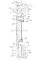
フライホイール組立体1は、エンジンで発生した動力を、クラッチ装置(図示せず)を介してトランスミッションに伝達するための装置である。図1及び図2に示すように、フライホイール組立体1は、第1フライホイール2(第1回転部材の一例)と、第2フライホイール3と、ダンパ機構4と、を備えている。
第1フライホイール2は、エンジンで発生した動力が入力される部材である。第1フライホイール2は、エンジンのクランクシャフト(図示せず)に固定されている。図1及び図2に示すように、第1フライホイール2は、第1プレート21と、第2プレート22と、支持部材23と、を有している。
第2フライホイール3は、第1フライホイール2に対して回転可能に配置されている。第2フライホイール3は、第2フライホイール本体31と、出力プレート33(第2回転部材の一例)と、を有している。出力プレート33は、リベット32により第2フライホイール本体31に固定されている。第2フライホイール3は、軸受39により第1フライホイール2に対して回転可能に支持されている。
ダンパ機構4は、第1フライホイール2と第2フライホイール3とを回転方向に弾性的に連結する機構である。ダンパ機構4は、4つの第1トーションスプリング41と、4つの第2トーションスプリング42と、4つの第1スプリングシート45(シート部材の一例)と、6つの第2スプリングシート46と、を有している。第1トーションスプリング41及び第2トーションスプリング42は、弾性部材の一例である。これらのトーションスプリング41,42及びスプリングシート45,46によって、2つのユニットが構成されている。図1では、一方のユニットのみを示している。
図1に示すように、それぞれ2つの第1及び第2トーションスプリング41,42は、第1フライホイール2及び第2フライホイール3の間で直列に作用するように配置されている。第1トーションスプリング41は比較的剛性の低いトーションスプリングであり、第2トーションスプリング42は比較的剛性の高いトーションスプリングである。そして、2つの第1トーションスプリング41で2つの第2トーションスプリング42を回転方向に挟むように配置されている。
第1スプリングシート45は、各収容空間Sの回転方向の端部に配置されている。すなわち、第1スプリングシート45は、第1及び第2側方部21b,22bの端部である外周部21e,22eに当接可能であるとともに、出力プレート33の伝達部33bに当接可能である。
第2スプリングシート46は、第1トーションスプリング41の他方の端部及び第2トーションスプリング42の両端部を、径方向及び軸方向に支持している。具体的には、第1トーションスプリング41の他端部と第2トーションスプリング42の一端部との間、及び2つの第2トーションスプリング42の間に、それぞれ配置されている。第2スプリングシート46は、樹脂製でブロック状に形成されている。第2スプリングシート46の回転方向の両側には、それぞれ第1トーションスプリング41の端部及び第2トーションスプリング42の端部を支持する凹部が形成されている。
前述のように、ダンパ機構4は2つのユニットによって構成されているが、ここでは、説明を容易にするために、一方のユニットに注目して説明を行う。
本発明はかかる実施形態に限定されるものではなく、本発明の範囲を逸脱することなく種々の変形及び修正が可能である。
2 第1フライホイール(第1回転部材の一例)
3 第2フライホイール
33 出力プレート(第2回転部材の一例)
33b 伝達部
33c 係合突起
41,42 トーションスプリング
45 第1スプリングシート(シート部材)
45a 凹部
45b 支持面
45c 当接面
45d 係合凹部
451 第1当接面
452 第2当接面
Claims (9)
- エンジンの動力が入力される第1回転部材と、
前記第1回転部材に対して相対回転可能に配置された第2回転部材と、
前記第1回転部材と前記第2回転部材とを回転方向に弾性的に連結する複数の弾性部材と、
前記第1回転部材及び前記第2回転部材の少なくともいずれか一方と前記弾性部材との間に配置され、前記弾性部材の伸縮に伴って回転方向に移動可能なシート部材と、
前記第1回転部材と前記第2回転部材との間の動力伝達時に、前記シート部材の姿勢を変更して前記弾性部材を所定量だけ圧縮する予備圧縮機構と、
を備えたダンパ装置。 - 前記予備圧縮機構は、前記シート部材に前記第1回転部材又は前記第2回転部材を当接させることにより前記シート部材の姿勢を変更し、前記弾性部材を圧縮する、請求項1に記載のダンパ装置。
- 前記シート部材は、前記第1回転部材又は前記第2回転部材の一部に択一的に当接可能な第1当接面及び第2当接面を有し、
前記予備圧縮機構は、前記シート部材の第1当接面及び第2当接面のいずれか一方を前記第1回転部材又は前記第2回転部材に当接させることにより前記シート部材の姿勢を変更し、前記弾性部材を圧縮する、
請求項2に記載のダンパ装置。 - 前記シート部材は、前記弾性部材の端面を支持する支持面を有し、
前記予備圧縮機構は、前記支持面の姿勢を変更することにより前記弾性部材を圧縮する、
請求項2又は3に記載のダンパ装置。 - 前記シート部材は、前記第1回転部材又は前記第2回転部材と当接する面に第1係合部を有し、
前記第1回転部材又は前記第2回転部材は、前記シート部材の第1係合部に係合可能であり、前記第1係合部に係合することにより前記シート部材の姿勢を変更する第2係合部を有している、
請求項3又は4に記載のダンパ装置。 - 前記第1係合部は回転方向に凹む凹部であり、
前記第2係合部は、回転方向に突出し前記凹部に係合可能な突起である、
請求項5に記載のダンパ装置。 - 前記第1回転部材は軸方向に凹む環状の収容部を有し、前記収容部は外周側内壁面を有し、
前記複数の弾性部材及び前記シート部材は、前記第1回転部材の収容部に収容されており、
前記シート部材は、前記弾性部材の回転方向の端部が外周側に移動するのを規制するための外周側支持部を有し、
前記シート部材の第1当接面及び第2当接面は、前記外周側支持部の外周面に形成され、前記収容部の外周側内壁面に択一的に当接可能であり、
前記シート部材は、前記第1当接面が前記外周側内壁面に当接する第1姿勢と、前記第2当接面が前記外周側内壁面に当接する第2姿勢とを取り得る、
請求項3から6のいずれかに記載のダンパ装置。 - 前記シート部材は、前記弾性部材の端面を支持する支持面を有し、
前記支持面は、前記シート部材が第1姿勢のときと前記第2姿勢のときとで姿勢が変化し、
前記弾性部材は、前記シート部材が前記第1姿勢から前記第2姿勢に変化するときに所定量だけ圧縮される、
請求項7に記載のダンパ装置。 - 前記シート部材は、回転方向の作動領域の全領域において前記第1回転部材の外周側内壁面に接している、請求項7又は8に記載のダンパ装置。
Priority Applications (4)
| Application Number | Priority Date | Filing Date | Title |
|---|---|---|---|
| JP2017128686A JP6767937B2 (ja) | 2017-06-30 | 2017-06-30 | ダンパ装置 |
| US15/995,425 US10895303B2 (en) | 2017-06-30 | 2018-06-01 | Damper device |
| CN201810581981.1A CN109210134B (zh) | 2017-06-30 | 2018-06-07 | 减震装置 |
| DE102018114645.0A DE102018114645A1 (de) | 2017-06-30 | 2018-06-19 | Dämpfervorrichtung |
Applications Claiming Priority (1)
| Application Number | Priority Date | Filing Date | Title |
|---|---|---|---|
| JP2017128686A JP6767937B2 (ja) | 2017-06-30 | 2017-06-30 | ダンパ装置 |
Publications (3)
| Publication Number | Publication Date |
|---|---|
| JP2019011816A JP2019011816A (ja) | 2019-01-24 |
| JP2019011816A5 JP2019011816A5 (ja) | 2019-06-27 |
| JP6767937B2 true JP6767937B2 (ja) | 2020-10-14 |
Family
ID=64661974
Family Applications (1)
| Application Number | Title | Priority Date | Filing Date |
|---|---|---|---|
| JP2017128686A Active JP6767937B2 (ja) | 2017-06-30 | 2017-06-30 | ダンパ装置 |
Country Status (4)
| Country | Link |
|---|---|
| US (1) | US10895303B2 (ja) |
| JP (1) | JP6767937B2 (ja) |
| CN (1) | CN109210134B (ja) |
| DE (1) | DE102018114645A1 (ja) |
Families Citing this family (1)
| Publication number | Priority date | Publication date | Assignee | Title |
|---|---|---|---|---|
| DE102019202254A1 (de) * | 2019-02-19 | 2020-08-20 | Volkswagen Aktiengesellschaft | Zweimassenschwungrad für den Antriebsstrang eines Fahrzeugs, insbesondere eines Kraftfahrzeugs |
Family Cites Families (10)
| Publication number | Priority date | Publication date | Assignee | Title |
|---|---|---|---|---|
| DE3407524A1 (de) | 1984-03-01 | 1985-09-05 | Fichtel & Sachs Ag, 8720 Schweinfurt | Torsionsschwingungsdaempfer mit weichem uebergang zwischen zwei federsystemen |
| FR2718813B1 (fr) | 1994-04-14 | 1996-07-12 | Valeo | Volant amortisseur, notamment pour véhicule automobile. |
| DE9414314U1 (de) | 1993-12-22 | 1994-11-24 | Fichtel & Sachs Ag | Torsionsschwingungsdämpfer mit einem Planetengetriebe |
| DE19830432A1 (de) * | 1998-07-08 | 2000-01-13 | Rohs Voigt Patentverwertungsge | Verfahren zur Dämpfung von Torsionsschwingungen sowie Torsionsschwingungsdämpfer |
| JP3848508B2 (ja) * | 1999-07-19 | 2006-11-22 | 株式会社エクセディ | ダンパー機構 |
| JP4016398B2 (ja) | 2003-03-20 | 2007-12-05 | 現代自動車株式会社 | ねじれ振動ダンパー |
| JP4490721B2 (ja) | 2004-04-12 | 2010-06-30 | 三菱自動車工業株式会社 | エンジンの失火検出装置及びエンジンの燃焼制御装置 |
| JP2015086965A (ja) * | 2013-10-31 | 2015-05-07 | 株式会社エクセディ | フライホイール組立体 |
| JP6460950B2 (ja) * | 2015-09-24 | 2019-01-30 | トヨタ自動車株式会社 | ダンパ装置 |
| JP2017166656A (ja) * | 2016-03-18 | 2017-09-21 | 本田技研工業株式会社 | トルク伝達装置 |
-
2017
- 2017-06-30 JP JP2017128686A patent/JP6767937B2/ja active Active
-
2018
- 2018-06-01 US US15/995,425 patent/US10895303B2/en active Active
- 2018-06-07 CN CN201810581981.1A patent/CN109210134B/zh active Active
- 2018-06-19 DE DE102018114645.0A patent/DE102018114645A1/de active Pending
Also Published As
| Publication number | Publication date |
|---|---|
| US20190003553A1 (en) | 2019-01-03 |
| DE102018114645A1 (de) | 2019-01-03 |
| CN109210134B (zh) | 2021-04-06 |
| CN109210134A (zh) | 2019-01-15 |
| JP2019011816A (ja) | 2019-01-24 |
| US10895303B2 (en) | 2021-01-19 |
Similar Documents
| Publication | Publication Date | Title |
|---|---|---|
| JP4489822B2 (ja) | フライホイール組立体 | |
| WO2010010896A1 (ja) | 動力伝達部品、ダンパー機構およびフライホイール組立体 | |
| JP6356652B2 (ja) | 変動減衰装置 | |
| JP2015086965A (ja) | フライホイール組立体 | |
| JP4625791B2 (ja) | スプリングシート及びスプリング組立体 | |
| WO2011138894A1 (ja) | ダンパー機構 | |
| JP6767937B2 (ja) | ダンパ装置 | |
| JP4932922B2 (ja) | フライホイール組立体 | |
| JP2017125579A (ja) | 車両用ダンパ装置 | |
| JP5388628B2 (ja) | ダンパー機構 | |
| KR100861761B1 (ko) | 더블 매스 플라이휠 | |
| JP6167839B2 (ja) | 車両用ダンパ装置 | |
| JP4451912B2 (ja) | ダンパー機構 | |
| KR100560095B1 (ko) | 플라이휠 조립체 | |
| JP4435249B2 (ja) | 動力伝達部品およびそれを備えたダンパー機構 | |
| JP4512654B2 (ja) | ダンパー機構 | |
| KR100855653B1 (ko) | 플라이휠 조립체 | |
| JP2005207552A (ja) | フライホイール組立体 | |
| JP5508874B2 (ja) | ダンパー | |
| JP4445249B2 (ja) | フライホイール組立体 | |
| WO2018051705A1 (ja) | ダンパ装置 | |
| JP2009174720A (ja) | トーションダンパ | |
| WO2005028915A1 (ja) | フレキシブルフライホイール | |
| JP4402934B2 (ja) | フレキシブルフライホイール | |
| JP2016142339A (ja) | トルク変動吸収装置 |
Legal Events
| Date | Code | Title | Description |
|---|---|---|---|
| A621 | Written request for application examination |
Free format text: JAPANESE INTERMEDIATE CODE: A621 Effective date: 20190319 |
|
| A521 | Request for written amendment filed |
Free format text: JAPANESE INTERMEDIATE CODE: A523 Effective date: 20190522 |
|
| A977 | Report on retrieval |
Free format text: JAPANESE INTERMEDIATE CODE: A971007 Effective date: 20200117 |
|
| A131 | Notification of reasons for refusal |
Free format text: JAPANESE INTERMEDIATE CODE: A131 Effective date: 20200128 |
|
| A521 | Request for written amendment filed |
Free format text: JAPANESE INTERMEDIATE CODE: A523 Effective date: 20200318 |
|
| TRDD | Decision of grant or rejection written | ||
| A01 | Written decision to grant a patent or to grant a registration (utility model) |
Free format text: JAPANESE INTERMEDIATE CODE: A01 Effective date: 20200901 |
|
| A61 | First payment of annual fees (during grant procedure) |
Free format text: JAPANESE INTERMEDIATE CODE: A61 Effective date: 20200918 |
|
| R150 | Certificate of patent or registration of utility model |
Ref document number: 6767937 Country of ref document: JP Free format text: JAPANESE INTERMEDIATE CODE: R150 |
|
| R250 | Receipt of annual fees |
Free format text: JAPANESE INTERMEDIATE CODE: R250 |