JP6637765B2 - Thermoelectric based thermal management system - Google Patents
Thermoelectric based thermal management system Download PDFInfo
- Publication number
- JP6637765B2 JP6637765B2 JP2015556085A JP2015556085A JP6637765B2 JP 6637765 B2 JP6637765 B2 JP 6637765B2 JP 2015556085 A JP2015556085 A JP 2015556085A JP 2015556085 A JP2015556085 A JP 2015556085A JP 6637765 B2 JP6637765 B2 JP 6637765B2
- Authority
- JP
- Japan
- Prior art keywords
- thermoelectric
- battery
- printed circuit
- circuit board
- thermoelectric device
- Prior art date
- Legal status (The legal status is an assumption and is not a legal conclusion. Google has not performed a legal analysis and makes no representation as to the accuracy of the status listed.)
- Expired - Fee Related
Links
- 239000004020 conductor Substances 0.000 claims description 83
- 238000001816 cooling Methods 0.000 claims description 60
- 239000002918 waste heat Substances 0.000 claims description 59
- 238000004891 communication Methods 0.000 claims description 57
- 238000010438 heat treatment Methods 0.000 claims description 47
- 238000000034 method Methods 0.000 claims description 39
- 238000012546 transfer Methods 0.000 claims description 34
- 239000000463 material Substances 0.000 claims description 14
- 238000007599 discharging Methods 0.000 claims description 11
- 239000004519 grease Substances 0.000 claims description 6
- 230000003247 decreasing effect Effects 0.000 claims description 5
- 238000004519 manufacturing process Methods 0.000 claims description 5
- 230000000712 assembly Effects 0.000 claims description 4
- 238000000429 assembly Methods 0.000 claims description 4
- 230000007423 decrease Effects 0.000 claims description 4
- 239000006260 foam Substances 0.000 claims description 4
- 239000000758 substrate Substances 0.000 claims description 4
- 238000009826 distribution Methods 0.000 claims description 3
- 238000007789 sealing Methods 0.000 claims description 2
- 210000004027 cell Anatomy 0.000 description 60
- 229920003258 poly(methylsilmethylene) Polymers 0.000 description 59
- 239000003570 air Substances 0.000 description 53
- 239000007788 liquid Substances 0.000 description 15
- 230000007246 mechanism Effects 0.000 description 13
- 230000008901 benefit Effects 0.000 description 11
- 239000007787 solid Substances 0.000 description 10
- 239000012530 fluid Substances 0.000 description 4
- 239000007789 gas Substances 0.000 description 4
- RYGMFSIKBFXOCR-UHFFFAOYSA-N Copper Chemical compound [Cu] RYGMFSIKBFXOCR-UHFFFAOYSA-N 0.000 description 3
- 239000008280 blood Substances 0.000 description 3
- 210000004369 blood Anatomy 0.000 description 3
- 230000007613 environmental effect Effects 0.000 description 3
- 230000036541 health Effects 0.000 description 3
- 238000009434 installation Methods 0.000 description 3
- 230000000670 limiting effect Effects 0.000 description 3
- 230000007257 malfunction Effects 0.000 description 3
- 238000012544 monitoring process Methods 0.000 description 3
- 238000013021 overheating Methods 0.000 description 3
- 230000004044 response Effects 0.000 description 3
- 230000015556 catabolic process Effects 0.000 description 2
- 239000000919 ceramic Substances 0.000 description 2
- 238000007906 compression Methods 0.000 description 2
- 230000006835 compression Effects 0.000 description 2
- 230000001143 conditioned effect Effects 0.000 description 2
- 239000002826 coolant Substances 0.000 description 2
- 239000010949 copper Substances 0.000 description 2
- 229910052802 copper Inorganic materials 0.000 description 2
- 238000006731 degradation reaction Methods 0.000 description 2
- 238000010586 diagram Methods 0.000 description 2
- 238000005516 engineering process Methods 0.000 description 2
- 238000012423 maintenance Methods 0.000 description 2
- 230000036961 partial effect Effects 0.000 description 2
- 239000004065 semiconductor Substances 0.000 description 2
- 238000005476 soldering Methods 0.000 description 2
- 239000007921 spray Substances 0.000 description 2
- 239000002699 waste material Substances 0.000 description 2
- 229910001369 Brass Inorganic materials 0.000 description 1
- HBBGRARXTFLTSG-UHFFFAOYSA-N Lithium ion Chemical compound [Li+] HBBGRARXTFLTSG-UHFFFAOYSA-N 0.000 description 1
- 230000006978 adaptation Effects 0.000 description 1
- 239000000853 adhesive Substances 0.000 description 1
- 230000001070 adhesive effect Effects 0.000 description 1
- 230000002411 adverse Effects 0.000 description 1
- 238000004378 air conditioning Methods 0.000 description 1
- XAGFODPZIPBFFR-UHFFFAOYSA-N aluminium Chemical compound [Al] XAGFODPZIPBFFR-UHFFFAOYSA-N 0.000 description 1
- 229910052782 aluminium Inorganic materials 0.000 description 1
- 239000012080 ambient air Substances 0.000 description 1
- 230000033228 biological regulation Effects 0.000 description 1
- 239000010951 brass Substances 0.000 description 1
- 238000004364 calculation method Methods 0.000 description 1
- 210000003850 cellular structure Anatomy 0.000 description 1
- 239000011889 copper foil Substances 0.000 description 1
- 238000013480 data collection Methods 0.000 description 1
- 230000001419 dependent effect Effects 0.000 description 1
- 238000013461 design Methods 0.000 description 1
- 230000006866 deterioration Effects 0.000 description 1
- 238000002296 dynamic light scattering Methods 0.000 description 1
- 230000000694 effects Effects 0.000 description 1
- 230000005611 electricity Effects 0.000 description 1
- 239000003822 epoxy resin Substances 0.000 description 1
- 238000000605 extraction Methods 0.000 description 1
- 239000002828 fuel tank Substances 0.000 description 1
- 230000017525 heat dissipation Effects 0.000 description 1
- 238000002955 isolation Methods 0.000 description 1
- 229910001416 lithium ion Inorganic materials 0.000 description 1
- 238000012986 modification Methods 0.000 description 1
- 230000004048 modification Effects 0.000 description 1
- 238000004806 packaging method and process Methods 0.000 description 1
- 239000004033 plastic Substances 0.000 description 1
- 229920000647 polyepoxide Polymers 0.000 description 1
- 238000013061 process characterization study Methods 0.000 description 1
- 238000004080 punching Methods 0.000 description 1
- 230000009467 reduction Effects 0.000 description 1
- 230000002829 reductive effect Effects 0.000 description 1
Images


Classifications
-
- H—ELECTRICITY
- H01—ELECTRIC ELEMENTS
- H01M—PROCESSES OR MEANS, e.g. BATTERIES, FOR THE DIRECT CONVERSION OF CHEMICAL ENERGY INTO ELECTRICAL ENERGY
- H01M10/00—Secondary cells; Manufacture thereof
- H01M10/60—Heating or cooling; Temperature control
- H01M10/65—Means for temperature control structurally associated with the cells
- H01M10/657—Means for temperature control structurally associated with the cells by electric or electromagnetic means
- H01M10/6572—Peltier elements or thermoelectric devices
-
- H—ELECTRICITY
- H01—ELECTRIC ELEMENTS
- H01M—PROCESSES OR MEANS, e.g. BATTERIES, FOR THE DIRECT CONVERSION OF CHEMICAL ENERGY INTO ELECTRICAL ENERGY
- H01M10/00—Secondary cells; Manufacture thereof
- H01M10/60—Heating or cooling; Temperature control
- H01M10/62—Heating or cooling; Temperature control specially adapted for specific applications
- H01M10/627—Stationary installations, e.g. power plant buffering or backup power supplies
-
- H—ELECTRICITY
- H01—ELECTRIC ELEMENTS
- H01M—PROCESSES OR MEANS, e.g. BATTERIES, FOR THE DIRECT CONVERSION OF CHEMICAL ENERGY INTO ELECTRICAL ENERGY
- H01M10/00—Secondary cells; Manufacture thereof
- H01M10/60—Heating or cooling; Temperature control
- H01M10/65—Means for temperature control structurally associated with the cells
- H01M10/655—Solid structures for heat exchange or heat conduction
-
- H—ELECTRICITY
- H02—GENERATION; CONVERSION OR DISTRIBUTION OF ELECTRIC POWER
- H02J—CIRCUIT ARRANGEMENTS OR SYSTEMS FOR SUPPLYING OR DISTRIBUTING ELECTRIC POWER; SYSTEMS FOR STORING ELECTRIC ENERGY
- H02J7/00—Circuit arrangements for charging or depolarising batteries or for supplying loads from batteries
- H02J7/0068—Battery or charger load switching, e.g. concurrent charging and load supply
-
- H—ELECTRICITY
- H05—ELECTRIC TECHNIQUES NOT OTHERWISE PROVIDED FOR
- H05K—PRINTED CIRCUITS; CASINGS OR CONSTRUCTIONAL DETAILS OF ELECTRIC APPARATUS; MANUFACTURE OF ASSEMBLAGES OF ELECTRICAL COMPONENTS
- H05K3/00—Apparatus or processes for manufacturing printed circuits
- H05K3/30—Assembling printed circuits with electric components, e.g. with resistor
- H05K3/32—Assembling printed circuits with electric components, e.g. with resistor electrically connecting electric components or wires to printed circuits
- H05K3/325—Assembling printed circuits with electric components, e.g. with resistor electrically connecting electric components or wires to printed circuits by abutting or pinching, i.e. without alloying process; mechanical auxiliary parts therefor
-
- H—ELECTRICITY
- H01—ELECTRIC ELEMENTS
- H01M—PROCESSES OR MEANS, e.g. BATTERIES, FOR THE DIRECT CONVERSION OF CHEMICAL ENERGY INTO ELECTRICAL ENERGY
- H01M10/00—Secondary cells; Manufacture thereof
- H01M10/60—Heating or cooling; Temperature control
- H01M10/61—Types of temperature control
- H01M10/613—Cooling or keeping cold
-
- H—ELECTRICITY
- H01—ELECTRIC ELEMENTS
- H01M—PROCESSES OR MEANS, e.g. BATTERIES, FOR THE DIRECT CONVERSION OF CHEMICAL ENERGY INTO ELECTRICAL ENERGY
- H01M10/00—Secondary cells; Manufacture thereof
- H01M10/60—Heating or cooling; Temperature control
- H01M10/61—Types of temperature control
- H01M10/615—Heating or keeping warm
-
- Y—GENERAL TAGGING OF NEW TECHNOLOGICAL DEVELOPMENTS; GENERAL TAGGING OF CROSS-SECTIONAL TECHNOLOGIES SPANNING OVER SEVERAL SECTIONS OF THE IPC; TECHNICAL SUBJECTS COVERED BY FORMER USPC CROSS-REFERENCE ART COLLECTIONS [XRACs] AND DIGESTS
- Y02—TECHNOLOGIES OR APPLICATIONS FOR MITIGATION OR ADAPTATION AGAINST CLIMATE CHANGE
- Y02E—REDUCTION OF GREENHOUSE GAS [GHG] EMISSIONS, RELATED TO ENERGY GENERATION, TRANSMISSION OR DISTRIBUTION
- Y02E60/00—Enabling technologies; Technologies with a potential or indirect contribution to GHG emissions mitigation
- Y02E60/10—Energy storage using batteries
-
- Y—GENERAL TAGGING OF NEW TECHNOLOGICAL DEVELOPMENTS; GENERAL TAGGING OF CROSS-SECTIONAL TECHNOLOGIES SPANNING OVER SEVERAL SECTIONS OF THE IPC; TECHNICAL SUBJECTS COVERED BY FORMER USPC CROSS-REFERENCE ART COLLECTIONS [XRACs] AND DIGESTS
- Y10—TECHNICAL SUBJECTS COVERED BY FORMER USPC
- Y10T—TECHNICAL SUBJECTS COVERED BY FORMER US CLASSIFICATION
- Y10T29/00—Metal working
- Y10T29/49—Method of mechanical manufacture
- Y10T29/49002—Electrical device making
- Y10T29/49108—Electric battery cell making
- Y10T29/49112—Electric battery cell making including laminating of indefinite length material
-
- Y—GENERAL TAGGING OF NEW TECHNOLOGICAL DEVELOPMENTS; GENERAL TAGGING OF CROSS-SECTIONAL TECHNOLOGIES SPANNING OVER SEVERAL SECTIONS OF THE IPC; TECHNICAL SUBJECTS COVERED BY FORMER USPC CROSS-REFERENCE ART COLLECTIONS [XRACs] AND DIGESTS
- Y10—TECHNICAL SUBJECTS COVERED BY FORMER USPC
- Y10T—TECHNICAL SUBJECTS COVERED BY FORMER US CLASSIFICATION
- Y10T29/00—Metal working
- Y10T29/49—Method of mechanical manufacture
- Y10T29/49002—Electrical device making
- Y10T29/49117—Conductor or circuit manufacturing
- Y10T29/49124—On flat or curved insulated base, e.g., printed circuit, etc.
- Y10T29/4913—Assembling to base an electrical component, e.g., capacitor, etc.
- Y10T29/49131—Assembling to base an electrical component, e.g., capacitor, etc. by utilizing optical sighting device
Landscapes
- Engineering & Computer Science (AREA)
- Manufacturing & Machinery (AREA)
- General Chemical & Material Sciences (AREA)
- Chemical & Material Sciences (AREA)
- Chemical Kinetics & Catalysis (AREA)
- Electrochemistry (AREA)
- Physics & Mathematics (AREA)
- Electromagnetism (AREA)
- Power Engineering (AREA)
- Metallurgy (AREA)
- Microelectronics & Electronic Packaging (AREA)
- Secondary Cells (AREA)
- Battery Mounting, Suspending (AREA)
- Connection Of Batteries Or Terminals (AREA)
Description
本開示は概して、電気装置の熱電(TE)冷却および加熱に関する。 The present disclosure relates generally to thermoelectric (TE) cooling and heating of electrical devices.
パワーエレクトロニクスおよびバッテリなどの他の電気装置は、過熱、低温、極端な温度、および動作温度制限に敏感であり得る。このような機器の性能は、機器が推奨温度範囲外で動作される場合には、場合によっては大幅に低下し得る。半導体装置では、集積回路ダイが過熱し、誤作動し得る。例えば、電気自動車などの自動車への用途で用いられるバッテリを含むバッテリでは、バッテリセルおよびその構成部品は、過熱または過冷却されると劣化し得る。このような劣化は、バッテリの蓄電量の低下、および/または、複数のデューティーサイクルにわたって充電されるバッテリの充電能力の低下となって現れ得る。 Other electrical devices, such as power electronics and batteries, can be sensitive to overheating, low temperatures, extreme temperatures, and operating temperature limitations. The performance of such equipment can be significantly reduced in some cases if the equipment is operated outside the recommended temperature range. In semiconductor devices, integrated circuit dies can overheat and malfunction. For example, in batteries, including batteries used in automotive applications such as electric vehicles, the battery cells and their components may degrade when overheated or overcooled. Such deterioration may be manifested as a decrease in the charge of the battery and / or a decrease in the charging capacity of the battery charged over a plurality of duty cycles.
パワーエレクトロニクスおよび他の電気装置の熱的状態を管理することが有利であり得る。熱管理は、過熱、過冷却、および電気装置の劣化の発生率を低下させることができる。本明細書に記載される、ある実施形態は、多大な電力を運び、および/または、大電流および高い効率を要する機器(例えば、電力増幅器、トランジスタ、変圧器、電力インバータ、絶縁ゲートバイポーラトランジスタ(IGBT)、電気モータ、高出力レーザ、発光ダイオード、バッテリおよび他の機器)の熱管理を提供する。対流空気および液体の冷却、伝導冷却、液体ジェットによるスプレー冷却、ボードおよびチップケースの熱電冷却、ならびに他の解決策を含む、広範囲の解決策がこのような機器の熱管理に用いることができる。本明細書に開示される少なくともいくつかの実施形態は、電気装置を加熱または冷却する既存の技術と比較して、高電力効率、低いかゼロの維持コスト、高い信頼性、長寿命、少数の構成部品、少ないかゼロの可動部品、加熱および冷却動作モード、他の利点、または利点の組み合わせといった利点の、少なくとも1つを提供する。 It may be advantageous to manage the thermal state of power electronics and other electrical devices. Thermal management can reduce the incidence of overheating, subcooling, and degradation of electrical devices. Certain embodiments described herein are devices that carry large amounts of power and / or require large currents and high efficiencies (eg, power amplifiers, transistors, transformers, power inverters, insulated gate bipolar transistors ( IGBT), electric motors, high power lasers, light emitting diodes, batteries and other equipment). A wide range of solutions can be used for thermal management of such equipment, including convection air and liquid cooling, conduction cooling, spray cooling with liquid jets, thermoelectric cooling of boards and chip cases, and other solutions. At least some embodiments disclosed herein have high power efficiency, low or zero maintenance cost, high reliability, long life, low number of components compared to existing technologies for heating or cooling electrical devices. It provides at least one of the advantages of components, few or zero moving parts, heating and cooling modes of operation, other advantages, or a combination of advantages.
電気装置において、通常機器の電気的活性部分および/または温度敏感領域は、導電体を介して、例えば外部回路または機器などの外界に接続される。たとえば、バッテリセルの電極は、大きな損失(例えば、ジュールの法則による、電流の二乗に比例する熱損失)なしに大電力を運ぶように設計され得る。このような電極に用いられる導電体のワイヤゲージは、通常このような機器を流れる大電流に釣り合うものである。バッテリのサイズが大きいほど、外部回路と接続するための電極端子も大きくなる。 In an electrical device, the electrically active part and / or the temperature-sensitive area of the equipment are usually connected via conductors to the outside world, for example external circuits or equipment. For example, the electrodes of a battery cell can be designed to carry large amounts of power without significant loss (eg, heat loss proportional to the square of the current according to Joule's law). The wire gauge of the conductor used for such an electrode is usually proportional to the large current flowing through such a device. The larger the size of the battery, the larger the electrode terminals for connecting to an external circuit.
電極および多くの他の種類の導電体の高い導電率は、このような導電体が、通常高い熱伝導率を有するということも意味している。高い熱伝導率は、様々な熱管理の問題を解決するために用いることができ、機器の熱に鈍感な素子をバイパスして電極を加熱および/または冷却することによって、所望の熱出力(例えば、冷却、加熱など)を機器の敏感な素子に直接送ることができる。人体の内部深くに熱を伝えるために、輸血の間、熱的に調整された血液を用いるのと同様に、電極を通して熱を送り込むことは、所望の熱状態を電気装置の内部深くに効率的に伝えるために用いることができる。例として、高度な自動車用バッテリの電極冷却は、バッテリの熱管理に関して最も有利な技術の1つであることがわかっている。例えば、電極は、個体、液体または気体の冷却技術を用いて冷却することができる。ある意味では、電極はそのような熱管理配置においてコールドフィンガ(cold finger)として働く。 The high conductivity of the electrodes and many other types of conductors also means that such conductors typically have high thermal conductivity. High thermal conductivity can be used to solve various thermal management problems, and by heating and / or cooling the electrodes by bypassing the heat-insensitive elements of the equipment, the desired heat output (eg, , Cooling, heating, etc.) can be sent directly to the sensitive elements of the equipment. Sending heat through electrodes, as well as using thermally conditioned blood during a blood transfusion to transfer heat deep inside the human body, effectively transfers the desired thermal state deep inside the electrical device. Can be used to communicate to As an example, advanced automotive battery electrode cooling has proven to be one of the most advantageous techniques for battery thermal management. For example, the electrodes can be cooled using solid, liquid or gas cooling techniques. In a sense, the electrode acts as a cold finger in such a thermal management arrangement.
本明細書に開示される実施形態は、電力構成部品、電子機器、および他の電気装置の電流を流す導電体(例えば、電極)に直接的または間接的に熱電(TE)冷却および/または加熱を加えることによって、電気装置を熱的に管理することが可能なシステムおよび方法を含む。このような機器はしばしば、熱管理による利益を受けることができる。いくつかの実施形態は、例えばバッテリなどの特定の電気装置に関して記載される。しかしながら、本明細書に開示される少なくともいくつかの実施形態は、例えば、絶縁ゲートバイポーラトランジスタ(IGBT)、他の電気装置、または機器の組み合わせなど、他の電気装置に対して熱管理を提供することができる。少なくともいくつかのこのような機器は、大電流を流すことができ、好ましい温度範囲外の動作を被るおそれがある。いくつかの実施形態の動作は、冷却動作モードに関して記載される。しかしながら、本明細書に開示されるいくつかまたは全ての実施形態は、加熱動作モードも同様に有し得る。いくつかの状況においては、加熱動作モードは、電気装置の温度を、それ未満では電気装置が劣化するか正常に動作しないおそれのある閾値温度を上回って維持するために用いることができる。TE装置は、システム構造に関する複雑さを最小限にして加熱機能および冷却機能の両方を提供するのに特に適している。 Embodiments disclosed herein provide for direct or indirect thermoelectric (TE) cooling and / or heating of current carrying conductors (eg, electrodes) of power components, electronics, and other electrical devices. Include systems and methods capable of thermally managing electrical devices. Such equipment can often benefit from thermal management. Some embodiments are described with respect to certain electrical devices, such as, for example, a battery. However, at least some embodiments disclosed herein provide thermal management for other electrical devices, such as, for example, insulated gate bipolar transistors (IGBTs), other electrical devices, or combinations of equipment. be able to. At least some such devices are capable of carrying large currents and may experience operation outside of the preferred temperature range. The operation of some embodiments is described with respect to a cooling mode of operation. However, some or all embodiments disclosed herein may have a heating mode of operation as well. In some situations, the heating mode of operation can be used to maintain the temperature of the electrical device above a threshold temperature below which the electrical device may degrade or malfunction. TE devices are particularly suitable for providing both heating and cooling functions with minimal complexity regarding the system structure.
本明細書に開示される実施形態は、熱電ベースの熱管理システムおよび方法を含む。いくつかの実施形態において、熱管理システムは電気装置の温度敏感領域の温度を管理するように構成される。熱管理システムは、熱電装置への電力印加時に、主面と廃熱面との間で熱エネルギーを伝達するように構成される熱電装置を含み得る。いくつかの実施形態において、熱電装置の主面は導電体の熱交換面と実質的に熱連通している。導電体は、電気装置の温度敏感領域と熱電装置との間で熱エネルギーを伝える導管として働くように、電気装置へ、または電気装置から電力を送るように構成される。 Embodiments disclosed herein include thermoelectric-based thermal management systems and methods. In some embodiments, the thermal management system is configured to manage the temperature of a temperature-sensitive area of the electrical device. The thermal management system may include a thermoelectric device configured to transfer thermal energy between the main surface and the waste heat surface when power is applied to the thermoelectric device. In some embodiments, a major surface of the thermoelectric device is in substantial thermal communication with a heat exchange surface of the electrical conductor. The electrical conductor is configured to transmit power to and from the electrical device to act as a conduit for transferring thermal energy between the temperature-sensitive region of the electrical device and the thermoelectric device.
特定の実施形態において、電気装置を熱的に管理する方法は、導電部分および非導電部分を備える熱伝達装置を、電気装置の複数の導電体に接続することを含んでいる。この方法は、熱伝達装置と熱電装置の主面との間で、実質的な熱エネルギーの交換を導くことを含み得る。 In certain embodiments, a method for thermally managing an electrical device includes connecting a heat transfer device comprising a conductive portion and a non-conductive portion to a plurality of electrical conductors of the electrical device. The method may include directing a substantial exchange of thermal energy between the heat transfer device and a major surface of the thermoelectric device.
いくつかの実施形態において、電気装置を熱的に管理する方法は、熱電装置と、電気装置と熱連通および電気連通している導電体の熱交換面との間で、実質的な熱連通を確立することを含む。この方法は、熱電装置内または熱電装置外に送られる電流を調節することにより、電気装置を加熱または冷却することを含み得る。 In some embodiments, a method of thermally managing an electrical device includes providing substantial thermal communication between the thermoelectric device and a heat exchange surface of a conductor in thermal communication with and electrical communication with the electrical device. Including establishing. The method may include heating or cooling the electrical device by adjusting an electrical current sent into or out of the thermoelectric device.
特定の実施形態において、バッテリセルの充電および放電を制御するように構成されるバッテリ管理制御装置を備えるバッテリセルの温度敏感領域の温度を管理するように構成される、熱電バッテリの熱管理システムが提供される。システムは、熱電装置に送られる電力を制御するように構成される熱電管理制御装置を備え、熱電装置は、熱電装置への電力印加時に、主面と廃熱面との間で熱エネルギーを伝達するように構成される。熱電装置の主面はバスバーに取り付けられており、バスバーはバッテリセルの導電体と実質的に熱連通している。導電体は、バッテリセルへ、またはバッテリセルから電力を送るように構成され、バッテリセルの温度敏感領域と熱電装置との間で熱エネルギーを伝える導管として働く。システムは、バッテリセルを収納するバッテリ筐体を備える。システムは、バッテリ管理制御装置と、熱電管理制御装置と、バッテリ管理制御装置および熱電管理制御装置の間のデータ接続部とを含むプリント回路基板を備える。プリント回路基板は、バッテリ筐体内に配置され、熱電装置に電力を供給するための電力接続部を備える。 In certain embodiments, a thermoelectric battery thermal management system configured to manage the temperature of a temperature sensitive region of a battery cell comprising a battery management controller configured to control charging and discharging of the battery cell is provided. Provided. The system includes a thermoelectric management controller configured to control power sent to the thermoelectric device, the thermoelectric device transferring thermal energy between the main surface and the waste heat surface when power is applied to the thermoelectric device. It is configured to The main surface of the thermoelectric device is attached to a bus bar, which is in substantial thermal communication with the conductors of the battery cells. The electrical conductor is configured to transfer power to and from the battery cell and acts as a conduit for transferring thermal energy between the temperature-sensitive region of the battery cell and the thermoelectric device. The system includes a battery housing that houses the battery cells. The system includes a printed circuit board that includes a battery management controller, a thermoelectric management controller, and a data connection between the battery management controller and the thermoelectric management controller. The printed circuit board is disposed in the battery housing and includes a power connection for supplying power to the thermoelectric device.
いくつかの実施形態において、熱電バッテリの熱管理システムは、熱電管理制御装置と電気連通し、熱電装置に提供される電流の極性を制御するように構成される制御装置を備える。電流の第1の極性は、システム動作の冷却モードにおいて提供され、第1の極性とは反対の電流の第2の極性は、システム動作の加熱モードにおいて提供される。 In some embodiments, the thermoelectric battery thermal management system includes a controller in electrical communication with the thermoelectric management controller and configured to control the polarity of the current provided to the thermoelectric device. A first polarity of current is provided in a cooling mode of system operation, and a second polarity of current opposite to the first polarity is provided in a heating mode of system operation.
いくつかの実施形態において、バッテリ管理制御装置は、バッテリセルに制御機能を与えるように構成される。 In some embodiments, the battery management controller is configured to provide control functions to the battery cells.
いくつかの実施形態において、熱電バッテリの熱管理システムは、バッテリセルと熱連通し、熱電管理制御装置と電気連通する温度センサを備える。 In some embodiments, the thermoelectric battery thermal management system includes a temperature sensor in thermal communication with the battery cell and in electrical communication with the thermoelectric management controller.
いくつかの実施形態において、プリント回路基板は、熱電装置を受け取るように構成される切欠部を備える。 In some embodiments, the printed circuit board includes a notch configured to receive the thermoelectric device.
いくつかの実施形態において、バスバーの表面は、導電体の表面と直接的に物理接触している。 In some embodiments, the busbar surface is in direct physical contact with the conductor surface.
いくつかの実施形態において、熱電バッテリの熱管理システムは、プリント回路基板に取り付けられ、熱電装置の廃熱面を横切って空気を押し出すように、または引き出すように構成されるブロワおよびダクトのアセンブリを備える。ブロワおよびダクトのアセンブリは、バッテリ管理制御装置および熱電管理制御装置の少なくとも1つが、ブロワからの空気流がバッテリセルの冷却要求または加熱要求に合致するように増加または減少されるようシステム効率を最適化するように構成されるように、バッテリ管理制御装置および熱電管理制御装置の少なくとも1つと電気連通している制御装置を備える。 In some embodiments, the thermoelectric battery thermal management system includes a blower and duct assembly attached to the printed circuit board and configured to push or pull air across the waste heat surface of the thermoelectric device. Prepare. The blower and duct assembly optimizes system efficiency such that at least one of the battery management controller and the thermoelectric management controller is increased or decreased so that airflow from the blower is matched to the cooling or heating requirements of the battery cells. A control device in electrical communication with at least one of the battery management control device and the thermoelectric management control device.
いくつかの実施形態において、バスバーは、プリント回路基板および導電体にバスバーを装着するための1つまたは2つ以上の装着孔を備える。 In some embodiments, the busbar includes one or more mounting holes for mounting the busbar to a printed circuit board and a conductor.
いくつかの実施形態において、バッテリセルは、筐体内にシールされ、筐体は、熱電装置に当接する高い熱伝導性材料のウィンドウを備え、ウィンドウは、ウィンドウの外部に配置される廃棄熱除去システムの部分と、熱電装置の廃熱面との間に、実質的な熱連通のためのアクセスを提供するように構成される。 In some embodiments, the battery cells are sealed within a housing, the housing comprising a window of a highly thermally conductive material abutting the thermoelectric device, wherein the window is disposed outside the window. And a waste heat surface of the thermoelectric device is configured to provide access for substantial thermal communication.
いくつかの実施形態において、熱電装置は、バスバーの上面および底面の両方に取り付けられている。 In some embodiments, thermoelectric devices are mounted on both the top and bottom surfaces of the busbar.
特定の実施形態において、バッテリセルを熱的に管理する方法は、プリント回路基板に取り付けられるバッテリ管理制御装置を用いて、バッテリセルの充電および放電を制御することを含んでいる。方法は、プリント回路基板に取り付けられる熱電管理制御装置を用いて、熱電装置に送られる電力を制御することを含んでいる。方法は、プリント回路基板に取り付けられる電力接続部から熱電装置へ電力を供給することを含んでいる。熱電装置は、熱電装置への電力印加時に、主面と廃熱面との間で熱エネルギーを伝達するように構成される。熱電装置の主面は、バスバーと物理接触している。バスバーは、バッテリセルの電極と熱連通および電気連通している。電極は、バッテリセルへ、またはバッテリセルから電力を送り、バッテリセルの温度敏感領域と熱電装置との間で熱エネルギーを伝える導管として働くように構成される。バッテリセルは、熱電装置に送られる電流の極性を調節することによって、加熱または冷却されることが可能である。 In certain embodiments, a method of thermally managing a battery cell includes controlling charging and discharging of the battery cell using a battery management controller attached to a printed circuit board. The method includes controlling power delivered to the thermoelectric device using a thermoelectric management controller attached to the printed circuit board. The method includes providing power to the thermoelectric device from a power connection attached to the printed circuit board. The thermoelectric device is configured to transfer thermal energy between the main surface and the waste heat surface when power is applied to the thermoelectric device. The main surface of the thermoelectric device is in physical contact with the bus bar. The busbar is in thermal and electrical communication with the battery cell electrodes. The electrodes are configured to transmit power to and from the battery cells and to serve as conduits for transferring thermal energy between the temperature-sensitive regions of the battery cells and the thermoelectric device. Battery cells can be heated or cooled by adjusting the polarity of the current sent to the thermoelectric device.
いくつかの実施形態において、熱電管理制御装置は、熱電装置に提供される電流の極性を制御するように構成され、電流の第1の極性は、システム動作の冷却モードにおいて提供され、第1の極性とは反対の電流の第2の極性は、システム動作の加熱モードにおいて提供される。 In some embodiments, the thermoelectric management controller is configured to control a polarity of a current provided to the thermoelectric device, wherein the first polarity of the current is provided in a cooling mode of system operation; A second polarity of current, opposite the polarity, is provided in a heating mode of system operation.
いくつかの実施形態において、バッテリ管理制御装置は、バッテリセルの充電および放電を管理するように構成される。 In some embodiments, the battery management controller is configured to manage charging and discharging of the battery cells.
いくつかの実施形態において、バッテリセルと熱連通し、熱電管理制御装置と電気連通する温度センサが設けられる。 In some embodiments, a temperature sensor is provided in thermal communication with the battery cell and in electrical communication with the thermoelectric management controller.
いくつかの実施形態において、プリント回路基板は、熱電装置を受け取るように構成される切欠部を備える。 In some embodiments, the printed circuit board includes a notch configured to receive the thermoelectric device.
いくつかの実施形態において、バスバーの表面は、導電体の表面と直接的に物理接触している。 In some embodiments, the busbar surface is in direct physical contact with the conductor surface.
いくつかの実施形態において、ブロワおよびダクトのアセンブリは、プリント回路基板に取り付けられ、熱電装置の廃熱面を横切って空気を押し出すように、または引き出すように構成される。ブロワおよびダクトのアセンブリは、バッテリ管理制御装置および熱電管理制御装置の少なくとも1つが、ブロワからの空気流がバッテリセルの冷却要求または加熱要求に合致するように増加または減少されるようシステム効率を最適化するように構成されるように、バッテリ管理制御装置および熱電管理制御装置の少なくとも1つと電気連通している制御装置を備える。 In some embodiments, the blower and duct assembly is attached to a printed circuit board and configured to push or pull air across the waste heat surface of the thermoelectric device. The blower and duct assembly optimizes system efficiency such that at least one of the battery management controller and the thermoelectric management controller is increased or decreased so that airflow from the blower is matched to the cooling or heating requirements of the battery cells. A control device in electrical communication with at least one of the battery management control device and the thermoelectric management control device.
いくつかの実施形態において、バスバーは、プリント回路基板および導電体にバスバーを装着するための1つまたは2つ以上の装着孔を備える。 In some embodiments, the busbar includes one or more mounting holes for mounting the busbar to a printed circuit board and a conductor.
いくつかの実施形態において、バッテリセルは、筐体内にシールされ、筐体は、熱電装置に当接するウィンドウを備え、ウィンドウは、ウィンドウの外部に配置される廃棄熱除去システムの部分と、熱電装置の廃熱面との間に、実質的な熱連通のためのアクセスを提供するように構成される。 In some embodiments, the battery cells are sealed within a housing, the housing comprising a window abutting the thermoelectric device, the window comprising a portion of a waste heat removal system located outside the window; And is configured to provide access for substantial thermal communication with the waste heat surface.
いくつかの実施形態において、熱電装置は、バスバーの上面および底面の両方に取り付けられている。 In some embodiments, thermoelectric devices are mounted on both the top and bottom surfaces of the busbar.
特定の実施形態において、バッテリセルの充電および放電を制御するように構成されるバッテリ管理システムと、熱電装置に送られる電力を制御するように構成される熱電管理システムとに、プリント回路基板を接続することを含む、熱電バッテリの熱管理システムを製造する方法が提供される。熱電装置は、熱電装置への電力印加時に、主面と廃熱面との間で熱エネルギーを伝達するように構成される。方法は、熱電装置の主面をバスバーに取り付け、バッテリセルと熱連通および電気連通している導電体にバスバーを接続することを含んでいる。導電体は、バッテリセルの温度敏感領域と熱電装置との間で熱エネルギーを伝える導管として働くように、バッテリセルへ、またはバッテリセルから電力を送るように構成される。方法は、熱電装置に電力を供給するために、プリント回路基板上に配置される電力接続部を熱電装置に接続することを含んでいる。 In certain embodiments, a printed circuit board is connected to a battery management system configured to control charging and discharging of battery cells and a thermoelectric management system configured to control power delivered to a thermoelectric device. A method of manufacturing a thermal management system for a thermoelectric battery is provided. The thermoelectric device is configured to transfer thermal energy between the main surface and the waste heat surface when power is applied to the thermoelectric device. The method includes attaching a major surface of the thermoelectric device to the busbar and connecting the busbar to an electrical conductor in thermal and electrical communication with the battery cell. The electrical conductor is configured to transmit power to and from the battery cell to act as a conduit for transferring thermal energy between the temperature sensitive region of the battery cell and the thermoelectric device. The method includes connecting a power connection located on a printed circuit board to the thermoelectric device to supply power to the thermoelectric device.
いくつかの実施形態において、方法は、制御装置を熱電管理システムに接続することを含み、制御装置は、熱電装置に提供される電流の極性を制御するように構成される。電流の第1の極性は、システム動作の冷却モードにおいて提供され、第1の極性と反対の電流の第2の極性は、システム動作の加熱モードにおいて提供される。 In some embodiments, the method includes connecting the controller to a thermoelectric management system, wherein the controller is configured to control the polarity of the current provided to the thermoelectric device. A first polarity of current is provided in a cooling mode of system operation, and a second polarity of current opposite to the first polarity is provided in a heating mode of system operation.
いくつかの実施形態において、方法は、制御装置を、バッテリセルに制御機能を与えるように構成されるバッテリ管理システムに接続することを含んでいる。 In some embodiments, the method includes connecting the controller to a battery management system configured to provide control functions to the battery cells.
いくつかの実施形態において、方法は、温度センサを、バッテリセルと熱連通して接続し、熱電管理制御装置と電気連通して接続することを含んでいる。 In some embodiments, the method includes connecting the temperature sensor in thermal communication with the battery cell and in electrical communication with the thermoelectric management controller.
いくつかの実施形態において、方法は、熱電装置を受け取るように構成されるプリント回路に切欠部を形成することを含んでいる。 In some embodiments, the method includes forming a cutout in the printed circuit configured to receive the thermoelectric device.
いくつかの実施形態において、方法は、バスバーの表面が導電体の表面と直接的に物理接触するように、バスバーを導電体に接続することを含んでいる。 In some embodiments, the method includes connecting the busbar to the electrical conductor such that the surface of the busbar is in direct physical contact with the surface of the electrical conductor.
いくつかの実施形態において、方法は、ブロワおよびダクトのアセンブリをプリント回路基板に取り付けることを含み、ブロワおよびダクトのアセンブリは、熱電装置の廃熱面を横切って空気を押し出すように、または引き出すように構成されている。ブロワおよびダクトのアセンブリは、バッテリ管理システムおよび熱電管理システムの少なくとも1つが、ブロワからの空気流がバッテリセルの冷却要求または加熱要求に合致するように増加または減少されるようシステム効率を最適化するように構成されるように、バッテリ管理システムおよび熱電管理システムの少なくとも1つと電気連通する制御装置を備える。 In some embodiments, the method includes attaching the blower and duct assembly to a printed circuit board, wherein the blower and duct assembly pushes or pulls air across the waste heat surface of the thermoelectric device. Is configured. The blower and duct assembly optimizes system efficiency such that at least one of the battery management system and the thermoelectric management system is increased or decreased so that airflow from the blower is matched to the cooling or heating requirements of the battery cells. And a controller in electrical communication with at least one of the battery management system and the thermoelectric management system.
いくつかの実施形態において、方法は、プリント回路基板および導電体にバスバーを取り付けることを含んでいる。 In some embodiments, the method includes attaching a bus bar to the printed circuit board and the conductor.
いくつかの実施形態において、方法は、バッテリセルを筐体内にシールすることを含み、筐体は、熱電装置に当接するウィンドウを備え、ウィンドウは、ウィンドウの外部に配置される廃棄熱除去システムの部分と、熱電装置の廃熱面との間の実質的な熱連通のためのアクセスを提供するように構成される。 In some embodiments, the method includes sealing the battery cell within a housing, the housing comprising a window abutting the thermoelectric device, wherein the window is disposed outside the window. It is configured to provide access for substantial thermal communication between the portion and a waste heat surface of the thermoelectric device.
いくつかの実施形態において、方法は、バスバーの上面および底面の両方に熱電装置を取り付けることを含んでいる。 In some embodiments, the method includes attaching thermoelectric devices to both the top and bottom surfaces of the busbar.
例示を目的として様々な実施形態が付随する図面に記されているが、これらは決して本明細書に記載される熱電アセンブリまたはシステムの範囲を限定するものとは理解されるべきではない。また、開示される異なる実施形態の様々な特徴は、互いに組み合わせられて別の実施形態を形成してもよく、これも本開示の一部である。任意の特徴または構成が除去、変更または省略されてもよい。図面を通して、参照番号は参照要素間の対応を示すために再利用されてもよい。 Although various embodiments are illustrated in the accompanying drawings for purposes of illustration, they should in no way be understood as limiting the scope of the thermoelectric assemblies or systems described herein. Also, various features of the different disclosed embodiments may be combined with one another to form alternative embodiments, which are also part of the present disclosure. Any features or configurations may be removed, changed or omitted. Throughout the drawings, reference numbers may be reused to indicate correspondence between reference elements.
いくつかの実施形態および例が本明細書に開示されるが、本主題は、詳細に開示された実施形態における例を超えて、別の実施形態および/または使用、ならびに、その変形および均等物にまで及ぶ。したがって、本明細書に添付の請求項の範囲は、以下に説明される特定の実施形態のいずれにも限定されない。例えば、本明細書に開示される任意の方法または工程において、この方法または工程の作用または動作は、任意の適切な順番で実行でき、任意の特定の開示された順番に必ずしも限定されるものではない。さまざまな動作が、いくつかの実施形態を理解するのに有用なように、複数の個別の動作として、順番に説明される。しかし、説明の順番は、これらの動作が順番に依存することを意味すると解釈されるべきではない。さらに、本明細書に記載される構造、システムおよび/または装置は、一体化された構成品または分離した構成品として実装されるであろう。さまざまな実施形態を比較する目的で、これらの実施形態の特定の態様および利点が説明される。必ずしも、すべてのそれらの態様または利点が、任意の特定の実施形態によって達成されるとは限らない。したがって、例えば、さまざまな実施形態は、本明細書に教示され、または示唆されるであろう他の態様または利点を達成することなく、本明細書に説明されるように、1つの利点または一群の利点を達成するか、または最適化するように実現される。 Although several embodiments and examples are disclosed herein, the present subject matter may extend beyond the examples in the specifically disclosed embodiments to other embodiments and / or uses, and variations and equivalents thereof. Up to. Accordingly, the scope of the claims appended hereto is not limited to any of the specific embodiments described below. For example, in any method or step disclosed herein, the acts or acts of the method or step may be performed in any suitable order, and are not necessarily limited to any particular disclosed order. Absent. The various operations are described in turn as a plurality of individual operations, to help in understanding some embodiments. However, the order of description should not be construed as meaning that these operations are order-dependent. Further, the structures, systems and / or devices described herein may be implemented as an integrated component or a separate component. For purposes of comparing various embodiments, certain aspects and advantages of these embodiments are described. Not all those aspects or advantages are achieved by any particular embodiment. Thus, for example, various embodiments may provide one advantage or group of features, as described herein, without achieving other aspects or advantages as taught or suggested herein. To achieve or optimize.
電子機器および電気装置の熱状態を管理することは有利であり得る。そのような熱管理は、過熱、過冷却および電気装置の劣化の機会を減らすことができる。本明細書に記載されるいくつかの実施形態は、大電力を運び、および/または、大電流および高効率を必要とする装置(例えば、電力増幅器、トランジスタ、変圧器、電力インバータ、絶縁ゲートバイポーラトランジスタ(IGBT)、電気モータ、高出力レーザおよび発光ダイオード、バッテリ、および他の装置)の熱管理を提供する。対流空気および液体による冷却、伝導冷却(conductive cooling)、液体ジェットを使ったスプレー冷却、ボードおよびチップケースの熱電冷却および他の解決策を含む、広範囲の解決策がこのような装置を熱的に管理するために用いられ得る。本明細書に開示される少なくともいくつかの実施形態は、電気装置を加熱または冷却するための既存の技術と比較して、高い電力効率、より低いか、またはゼロの維持コスト、より大きい信頼性、より長い寿命、より少ない構成品、より少ないか、もしくはまったく存在しない可動部品、加熱および冷却動作モード、他の利点、または利点の組み合わせの少なくとも1つを提供する。 Managing the thermal state of electronics and electrical devices can be advantageous. Such thermal management can reduce the chances of overheating, subcooling, and degradation of electrical equipment. Some embodiments described herein are devices that carry high power and / or require high current and high efficiency (eg, power amplifiers, transistors, transformers, power inverters, insulated gate bipolar devices). Provides thermal management of transistors (IGBTs), electric motors, high power lasers and light emitting diodes, batteries, and other devices). A wide range of solutions, including convection air and liquid cooling, conductive cooling, spray cooling using liquid jets, thermoelectric cooling of boards and chip cases, and other solutions, have thermally enabled such devices. Can be used to manage. At least some embodiments disclosed herein have higher power efficiency, lower or zero maintenance costs, greater reliability, as compared to existing technologies for heating or cooling electrical devices. Providing at least one of a longer life, fewer components, fewer or no moving parts, heating and cooling modes of operation, other advantages, or a combination of advantages.
電気装置において、通常、装置の電気的活性部分および/または温度敏感領域は、導電体を介して、例えば外部回路または装置などの外界に接続される。例えば、バッテリセルの電極は、大きな損失(例えば、ジュールの法則にしたがって、電流の2乗に比例する熱損失)なしに、大電力を運ぶように設計されてもよい。そのような電極に用いられる導電体のワイヤゲージは、通常そのような装置に流れる大電流に耐えられるようになっている。バッテリのサイズが大きくなるにつれ、外部回路と接続するための電極端子は大きくなる。 In electrical devices, typically the electrically active portion of the device and / or the temperature-sensitive region is connected via conductors to the outside world, such as an external circuit or device. For example, the electrodes of a battery cell may be designed to carry large amounts of power without large losses (eg, heat loss proportional to the square of the current according to Joule's law). Conductor wire gauges used in such electrodes are typically capable of withstanding large currents flowing in such devices. As the size of the battery increases, the electrode terminal for connecting to an external circuit increases.
電極および多くの他の種類の導電体の高い導電率は、そのような導電体が通常高い熱伝導率を有していることも意味している。高い熱伝導率は、さまざまな熱管理問題を解決するために用いることができ、装置の熱に鈍感な要素をバイパスして電極を加熱および/または冷却することにより、装置の敏感な要素に直接に、所望の熱出力(例えば、冷却、加熱など)を伝達することを可能にする。人体の内部深くに熱を伝達するために、輸血の間、熱的に調整された血液を用いるのと同様に、電極を介して熱を送り込むことは、電気装置内の深くに、所望の熱状態を効率的に伝達するのに使うことができる。一例として、高度な自動車バッテリの電極冷却は、バッテリの熱管理のための最も有効な技術の一つであることが分かっている。例えば、電極は、固体、液体または気体の冷却技術を用いて冷却することができる。ある意味では、電極は、そのような熱管理配置においてコールドフィンガとして働く。 The high conductivity of the electrodes and many other types of conductors also means that such conductors typically have high thermal conductivity. High thermal conductivity can be used to solve a variety of thermal management problems, and by heating and / or cooling the electrodes, bypassing the heat-insensitive elements of the device, directly on sensitive elements of the device. The desired heat output (eg, cooling, heating, etc.). Sending heat through the electrodes, as well as using thermally conditioned blood during transfusion to transfer heat deep inside the human body, requires the desired heat deep within the electrical device. Can be used to communicate state efficiently. As an example, advanced automotive battery electrode cooling has been found to be one of the most effective techniques for battery thermal management. For example, the electrodes can be cooled using solid, liquid or gas cooling techniques. In a sense, the electrodes act as cold fingers in such a thermal management arrangement.
本明細書に開示される実施形態は、電力構成品、電子機器および他の電気装置の、電流を流す導電体(例えば、電極)に、直接的または間接的に熱電(TE)冷却および/または加熱を加えることにより、電気装置を熱的に管理することができるシステムおよび方法を含んでいる。そのような装置は、しばしば熱管理による利益を得ることができる。いくつかの実施形態は、例えばバッテリなどの特定の電気装置を参照して説明される。しかしながら、本明細書に開示される少なくともいくつかの実施形態は、例えば、絶縁ゲートバイポーラトランジスタ(IGBT)、他の電気装置または装置の組み合わせなど、他の電気装置に対して熱管理を提供することができる。少なくともいくつかのそのような装置は、大電流を流す能力を持ち、好適な温度範囲外の動作によって悪影響を受けるであろう。いくつかの実施形態の動作は、冷却動作モードを参照して説明される。しかしながら、本明細書に開示される実施形態のいくつかまたは全ては、加熱動作モードも有することができる。いくつかの状況において、加熱動作モードは、電気装置の温度を、それ未満では電気装置が劣化するか正常に動作しないおそれのある閾値温度を上回って維持するために用いられ得る。TE装置は、システム構造に対する複雑性を最小にしつつ、加熱および冷却の両方の機能を提供するのに特に適している。 Embodiments disclosed herein provide for direct or indirect thermoelectric (TE) cooling and / or cooling of current carrying conductors (eg, electrodes) of power components, electronics, and other electrical devices. Included are systems and methods that can provide thermal management of electrical devices by applying heating. Such devices can often benefit from thermal management. Some embodiments are described with reference to a particular electrical device, such as a battery. However, at least some embodiments disclosed herein provide thermal management for other electrical devices, such as, for example, insulated gate bipolar transistors (IGBTs), other electrical devices or combinations of devices. Can be. At least some such devices are capable of carrying large currents and will be adversely affected by operation outside of the preferred temperature range. The operation of some embodiments will be described with reference to a cooling mode of operation. However, some or all of the embodiments disclosed herein may also have a heating mode of operation. In some situations, the heating mode of operation may be used to maintain the temperature of the electrical device above a threshold temperature below which the electrical device may degrade or malfunction. TE devices are particularly suitable for providing both heating and cooling functions while minimizing complexity for the system structure.
TE装置が、導電体を冷却および/または加熱するというタスクのために使用されるさまざまな方法がある。本明細書に記載されるように、TE装置は、1つまたは2つ以上のTE素子、TE組み立て品、および/またはTEモジュールを含み得る。いくつかの実施形態では、TEシステムは、第1の側と、第1の側と反対側の第2の側とを含むTE装置を含み得る。いくつかの実施形態では、第1の側および第2の側は、主面および廃熱面、または、加熱面および冷却面であってもよい。TE装置は、電源と動作可能に結合され得る。電源は、TE装置に電圧を印加するように構成され得る。電圧が一方向に印加されると、一方の側(例えば、第1の側)は、熱を発生し、他方の側(例えば、第2の側)は、熱を吸収する。回路の極性を切り替えることにより、反対の効果が発生する。典型的な配置では、TE装置は、異種材料を含む閉回路を備える。DC電圧が閉回路に印加されると、異種材料の接合部分に温度差が生じる。電流の方向に依存して、熱は、特定の接合部分において放射されるか、または吸収される。いくつかの実施形態では、TE装置は、直列に接続された、いくつかの固体PおよびN型半導体素子を含む。いくつかの実施形態では、接合部分は、TE装置の低温側と高温側とを形成し得る2つの電気隔離部材(例えば、セラミックス板)の間に挟まれる。低温側は、冷却されるべき対象(例えば、導電体、熱管理下の電気装置など)に熱的に結合され、高温側は、熱を環境に発散するヒートシンクに熱的に結合されてもよい。いくつかの実施形態では、高温側が、加熱されるべき対象(例えば、導電体、熱管理下の電気装置など)に結合されてもよい。特定の非限定的な実施形態が以下に記載される。 There are various ways in which TE devices are used for the task of cooling and / or heating conductors. As described herein, a TE device may include one or more TE elements, TE assemblies, and / or TE modules. In some embodiments, a TE system may include a TE device that includes a first side and a second side opposite the first side. In some embodiments, the first side and the second side may be major surfaces and waste heat surfaces, or heating and cooling surfaces. The TE device may be operatively coupled to a power supply. The power supply may be configured to apply a voltage to the TE device. When a voltage is applied in one direction, one side (e.g., a first side) generates heat and the other side (e.g., a second side) absorbs heat. Switching the polarity of the circuit has the opposite effect. In a typical arrangement, the TE device comprises a closed circuit containing a dissimilar material. When a DC voltage is applied to the closed circuit, a temperature difference occurs at the junction between different materials. Depending on the direction of the current, heat is radiated or absorbed at a particular junction. In some embodiments, the TE device includes several solid-state P and N-type semiconductor elements connected in series. In some embodiments, the joint is sandwiched between two electrical isolation members (eg, ceramic plates) that can form the cold and hot sides of the TE device. The cold side may be thermally coupled to the object to be cooled (eg, electrical conductors, electrical devices under thermal management, etc.) and the hot side may be thermally coupled to a heat sink that dissipates heat to the environment. . In some embodiments, the hot side may be coupled to the object to be heated (eg, electrical conductors, thermally controlled electrical devices, etc.). Certain non-limiting embodiments are described below.
「実質的な熱連通」との用語は、本明細書においては広くかつ通常の意味で用いられており、例えば、熱連通境界での面間のぴったりとした接触;熱連通している面間の1つまたは2つ以上の熱伝達材料または装置;パッド、熱グリース、ペースト、1つまたは2つ以上の作業流体または面間に高い熱伝導率を有する他の構造を含む熱伝導材料システムを用いた固体面間の接続;他の適切な構造;または構造の組み合わせを含む。実質的な熱連通は、1つまたは2つ以上の境界材料を介して、直接的または間接的に接続される面間に発生し得る。 The term "substantially thermal communication" is used broadly and in a conventional sense herein, for example, for tight contact between surfaces at a thermal communication boundary; A heat transfer material system including one or more heat transfer materials or devices; pads, heat grease, paste, one or more working fluids or other structures having high thermal conductivity between surfaces. Connections between solid surfaces used; other suitable structures; or combinations of structures. Substantial thermal communication may occur between surfaces that are directly or indirectly connected via one or more boundary materials.
いくつかの実施形態においては、電気装置の効率的な動作を促進するために、電気装置に熱管理(加熱および/または冷却)を提供することが有利であり得る。例えば、導電体(例えば、バッテリまたはセルの電極)を通して電気装置(例えば、バッテリ、バッテリパック、単一または複数のバッテリモジュール、バッテリパックまたはモジュールのセルなど)を加熱および冷却することは、このような熱管理を実施する効率的な方法であり得る。バッテリパックのセルに分散される迅速な熱管理を提供するオプションの1つは、本明細書の特定の実施形態に記載されるように、熱電装置を1つまたは2つ以上のバッテリ電極と実質的に熱連通させることによって、バッテリに入る熱およびバッテリから出る熱の流れを制御することである。 In some embodiments, it may be advantageous to provide thermal management (heating and / or cooling) to the electrical device to facilitate efficient operation of the electrical device. For example, heating and cooling an electrical device (eg, a battery, battery pack, single or multiple battery modules, battery pack or module cells, etc.) through electrical conductors (eg, battery or cell electrodes) can be performed in this manner. It can be an efficient way to implement efficient thermal management. One option for providing rapid thermal management distributed to the cells of a battery pack is to connect the thermoelectric device to one or more battery electrodes substantially as described in certain embodiments herein. The purpose of this is to control the flow of heat into and out of the battery by thermal communication.
現在の多くの種類の再充電可能なバッテリ(例えば、ハイブリッド自動車のバッテリ、リチウムイオンバッテリ、スマートバッテリ)は、温度、充電状態および他の条件に応じて、変動する速度または異なる速度で充電および放電するように構成される。これらの種類のバッテリは、充電および/または放電中に、バッテリに加えられ、またはバッテリから引き出される電流または電圧を変更する制御装置を含み得る。制御装置は、バッテリの状態に基づき、電気の充電および/または放電を調節し得る。同一の制御装置または異なる制御装置が、セルの平衡化、環境管理、安全な動作領域の保護、データ収集、計算、報告などの、バッテリの他の側面を管理し得る。これらのバッテリ動作の側面を管理する1つまたは2つ以上の制御装置を含むシステムは、バッテリ管理システム(BMS)と呼ばれ得る。BMSは、損傷、極端な温度、および/または、バッテリ性能を劣化させる条件からバッテリを保護するために、バッテリおよび環境条件の状態を監視し得る。BMSは、バッテリまたはバッテリセルの、温度、電圧、充電または放電状態、健康状態、エネルギー容量および/または電流、他の環境条件を監視するために、1つまたは2つ以上の制御装置、センサ(例えば、サーミスタ、サーモカップル)、プロセッサ、集積回路、外部の通信データバス、変圧器、調整回路、電圧タップ、プリント回路基板(例えば、プリント回路板またはフレキシブルプリント回路)(PCS)を含み得る。 Many types of rechargeable batteries today (eg, hybrid vehicle batteries, lithium-ion batteries, smart batteries) charge and discharge at varying or different rates, depending on temperature, state of charge and other conditions. It is configured to These types of batteries may include a controller that changes the current or voltage applied to or drawn from the battery during charging and / or discharging. The controller may regulate the charging and / or discharging of electricity based on the state of the battery. The same controller or a different controller may manage other aspects of the battery, such as cell balancing, environmental management, safe operating area protection, data collection, calculation, reporting, and the like. Systems that include one or more controllers that manage these aspects of battery operation may be referred to as a battery management system (BMS). The BMS may monitor the condition of the battery and environmental conditions to protect the battery from damage, extreme temperatures, and / or conditions that degrade battery performance. The BMS may include one or more controllers, sensors, and / or sensors for monitoring the temperature, voltage, charge or discharge status, health, energy capacity and / or current, and other environmental conditions of a battery or battery cell. For example, it may include a thermistor, a thermocouple), a processor, an integrated circuit, an external communication data bus, a transformer, a regulation circuit, a voltage tap, a printed circuit board (eg, a printed circuit board or a flexible printed circuit) (PCS).
このような種類のバッテリまたはバッテリモジュールが熱電装置を用いて冷却または加熱されるとき、これらは熱電ベースの熱管理システム(TMS)に動作可能に接続され得る。このようなバッテリのBMSおよびTMSは、分離または個別のシステムであり得る(例えば、BMSおよびTMSの制御装置は異なるPCSに位置付けられてもよい)。いくつかの実施形態において、バッテリまたはバッテリモジュールは、一体型のBMSおよびTMSを含んでいる(例えば、BMSおよびTMSの制御装置は、バッテリ筐体内および/または同一のPCS上に位置付けられてもよい)。 As these types of batteries or battery modules are cooled or heated using thermoelectric devices, they can be operably connected to a thermoelectric-based thermal management system (TMS). The BMS and TMS of such a battery may be separate or separate systems (eg, the BMS and TMS controllers may be located in different PCSs). In some embodiments, the battery or battery module includes an integrated BMS and TMS (eg, the BMS and TMS controllers may be located in the battery housing and / or on the same PCS). ).
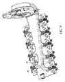
図1は、全体または一部において、本明細書に記載される実施形態、特徴、構造および動作モードのいずれかの特徴および態様を備え、または包含し得る電気装置を冷却および/または加熱するように構成される例示的な熱電バッテリの熱管理システム(TBTMS)1の概略図を示す。いくつかの実施形態において、TBTMS1は、一体型バッテリ管理システム2(BMS)と、一体型熱電管理システム4(TMS)と、1つまたは2つ以上の一体型バスバー6と、1つまたは2つ以上の導電体14(例えば、電極)を介してバッテリモジュール12に加熱および/または冷却をもたらす(全体として、および/または、所望の個別のセルまたはモジュールの特定の部分へ)ように構成される一体型のエアダクト8およびブロワ10のシステムとを備え得る。いくつかの実施形態において、エアダクト8は、空気以外の流体(例えば、液体、ガスなど)を流すように構成され得る。いくつかの実施形態において、TBTMS1は、以下にさらに記載されるように、1つまたは2つ以上の一体型バスバー6を介してバッテリモジュール12の少なくとも1つの導電体14(例えば、電流を流すコネクタ、電極、セルの一部、端子ワイヤ、電極間またはセルの部分間の配線、リード、正極および/または負極など)の熱交換面と実質的に熱連通している少なくとも1つのTE装置16を備え得る。TBTMS1の構成要素の1つまたは2つ以上は、以下にさらに詳細に記載されるように、バッテリモジュール12の様々な状態を制御および監視するため、および/または、バッテリモジュール12により電力(例えば、電圧、電流など)が供給されるために、プリント回路基板(PCS)30と一体化され得る。
FIG. 1 illustrates, in whole or in part, cooling and / or heating an electrical device that may comprise or include any of the features and aspects of the embodiments, features, structures and modes of operation described herein. 1 shows a schematic diagram of an exemplary thermoelectric battery thermal management system (TBTMS) 1 configured in FIG. In some embodiments, the TBTMS 1 includes an integrated battery management system 2 (BMS), an integrated thermoelectric management system 4 (TMS), one or more
いくつかの実施形態において、TE装置16は、TE装置16への電力(例えば、電圧および/または電流)印加時に、熱電装置の主面または主側と廃熱面または廃熱側との間で熱エネルギーを伝達するように構成される。熱電装置16の主面または廃熱面のいずれかは、1つまたは2つ以上の導電体14と実質的に熱連通するように構成され得る。1つまたは2つ以上の導電体14は、バッテリモジュール12のセルへ、またはバッテリモジュール12のセルから電力を送るように構成される。導電体14は、バッテリモジュール12のセルの温度敏感領域と、熱電装置16との間で、熱エネルギーを伝える導管として働くように動作可能である。
In some embodiments, the
このような例では、1つまたは2つ以上の導電体14は、バッテリモジュール12の温度敏感領域と、1つまたは2つ以上の外部装置との間で、電気エネルギーおよび熱エネルギーの両方を伝達することができる。冷却モードで動作するとき、熱Qは、1つまたは2つ以上の導電体14から送り出され、空気、液体、別の固体構成要素または構成要素の組み合わせである外部環境に発散される。加熱モードで動作するとき、熱出力は、反対方向に送られ、1つまたは2つ以上の導電体14を介して、熱をバッテリモジュール12内に送る。
In such an example, one or
図1に関して、いくつかの実施形態では、TBTMS1のバッテリモジュール12は、単機能のバッテリモジュール12を提供するために、互いに対して電気接続される複数のセル20を備え得る。いくつかの実施形態において、複数のバッテリモジュール12(例えば、2つまたは3つ以上)は、直列および/または並列のいずれかで電気連通するように互いに組み立てられ得る。いくつかの実施形態において、1つまたは2つ以上のバッテリモジュール12は、互いに隣接しておよび/または上下に配置または積層され得る。図1に示されるように、いくつかの実施形態において、バッテリモジュール12は、直列に電気接続された10の個別のセル20を備える。いくつかの実施形態において、バッテリモジュール12の個別のセル20は、導電性のバスバー6または他のコネクタもしくはコンダクタを介して、直列および/または並列に互いに電気接続され得る。いくつかの実施形態において、熱管理システム4は、1つまたは2つ以上のバスバー6を介してバッテリモジュール12の1つまたは2つ以上のセル20の1つまたは2つ以上の導電体14に一体化または接続される(例えば、実質的に熱連通する)1つまたは2つ以上の熱電装置16を含み得る。
With reference to FIG. 1, in some embodiments, the
図1に示されるように、一実施形態において、直列接続されるセル20は、バッテリモジュール12の上面に沿って延びる、2つの導電体14の平行列を有し得る。いくつかの実施形態において、1つまたは2つ以上の熱電装置16は、セラミック基板24の上面および底面に重ねられる銅基板または銅箔22か、または任意の他の適切な構成または材料を有するように構成され得る。いくつかの実施形態において、各熱電装置16の一方の側または一部は、少なくとも1つの一体型バスバー6に接続されるか、取り付けられるか、または一体化(例えば、はんだづけ、クリップ止め、粘着、接着、クランプ止め、または別の方法での取り付け)され得る。図1に示されるように、いくつかの実施形態において、第1の熱電装置16の第1の側は、バスバー6の上面に接続または一体化され、第2の熱電装置16の第1の側は、バスバー6の底面に接続または一体化され得る。
As shown in FIG. 1, in one embodiment, cells 20 connected in series may have two parallel rows of
いくつかの実施形態において、少なくとも1つの一体型バスバー6は、熱電装置16が1つまたは2つ以上の導電体と実質的に熱連通するように、2つまたは3つ以上のセル20(例えば、直列接続される2つの隣接するセル)の1つまたは2つ以上の導電体14に連結される。いくつかの実施形態において、少なくとも1つの導電体14は、少なくとも1つのTE装置16と実質的に熱連通していないか、または接続されていない。各熱電装置16の第2の側または部分は、少なくとも1つの熱伝達装置26に接続、はんだづけ、クリップ止め、粘着、接着、クランプ止め、または別の方法で取り付けられ得る。少なくとも1つの熱伝達装置26(例えば、熱交換器)は、フィン28を備え得る。いくつかの実施形態では、1つの熱伝達装置26が、各熱電装置16に取り付けられ得る。他の実施形態では、複数の熱伝達装置26が、各熱電装置16に取り付けられるか、または実質的に熱連通していてもよい。熱伝達装置26は、以下に記載されるような任意の廃棄熱除去システム(例えば、液体ループまたは導管、ダクトおよびブロワ)と熱連通し得る。
In some embodiments, at least one
いくつかの実施形態において、電気装置(例えば、電気自動車のバッテリまたはバッテリモジュール12)の既存の構成部品、セル、および/または回路、ならびに、電気装置の放電/充電速度、温度または他の状態を監視する電気装置の制御または管理システム(例えば、BMS2および/またはTMS4)と一体化されるように構成されるTBTMS1が提供される。このような一体型のTBTMS1は、組み立てや設置の問題を容易にし、構成要素やこのようなシステムに関わる複雑性を最小限にできる。いくつかの実施形態において、1つまたは2つ以上の構成要素は、組み立ておよび/または設置を容易にするために、単一の構成要素を電気装置に取り付ける前に、既存のまたは要求される構成要素(例えば、PCS30)と一体化され得る。図1に示されるように、バッテリモジュール12のTBTMS1は、例えばPCS30などの1つまたは2つ以上の構成要素に一体化されるように構成される、バッテリモジュール12のTMS4およびBMS2の両方、1つまたは2つ以上のバスバー6、1つまたは2つ以上の熱電装置16、1つまたは2つ以上の熱伝達装置26、ならびにエアダクト8およびブロワシステム10を備え得る。1つまたは2つ以上の構成要素がPCS30上に設置され一体化される(例えば、接続されまたは電気連通される)と、PCSはその後、バッテリモジュール12に連結され得る。このような例において、TBTMS1は、様々なシステムまたは構成要素(例えば、BMS2、TMS4、TE装置16など)への電気接続(例えば、バッテリモジュール12そのものや外部の電力源)のみを必要とし、これらの構成要素に電力を提供する。これらの種類のシステムまたはアセンブリは、このようなシステムの製造、設置および/または組み立てに関連する複雑性、構成要素、困難性、ステップ、および/またはコストを減少させ得る。
In some embodiments, existing components, cells, and / or circuits of an electrical device (eg, a battery or
いくつかの実施形態において、TBTMS1は、PCS30に一体化されるBMS2およびTMS4を備える(例えば、PCS30がBMS2をTMS4に接続するか、またはBMS2およびTMS4がPCSおよび/または集積回路を共有する)。BMS2は、バッテリモジュール12の充電および放電を制御するように構成される。TMS4は、1つまたは2つ以上のTE装置16に送られる電力(例えば、電流、電圧)を制御するように構成される制御装置(例えば、ECU)を含み得る。TE装置16は、主側および廃熱側を含み得る。主側は、TE装置16の、温度が制御される側であり得る。廃熱側は、TE装置16の、TMS4用の熱源またはヒートシンクとして働く側であり得る。いくつかの実施形態において、TMS4は、TE装置16の廃熱側に接続される熱源またはヒートシンクの温度を制御しない。TE装置16の主側は、バスバー6と実質的に熱連通し得る(例えば、直接的または間接的な物理接触または接着)。以下にさらに記載するように、各バスバー6は、バッテリセル、パックまたはモジュール12の1つまたは2つ以上の導電体14(例えば、電流を流すコネクタ、電極、セルの一部、端子ワイヤ、電極間またはセルの部分間の配線、リードなど)の熱交換面と実質的に熱連通し得る(例えば、直接的または間接的な物理接触または接着)。また、以下に記載するように、PCS30は、TE装置16への電力接続部(例えば、熱管理下にある電気装置(例えば、バッテリモジュール12)または外部の装置もしくは電力源から電力を供給するように構成される電気コネクタ50)を含み得る。例えば、TE装置16は、PCS30上に位置付けられる電気コネクタ50内へ「差し込まれ(plugged)」得る。
In some embodiments, TBTMS1 comprises BMS2 and TMS4 integrated into PCS30 (eg, PCS30 connects BMS2 to TMS4, or BMS2 and TMS4 share a PCS and / or integrated circuit). The BMS 2 is configured to control charging and discharging of the
図1に示し上述したように、いくつかの実施形態において、TMS4は、少なくとも1つのTE装置16を含み得る。TE装置16の表面(例えば、主側)は、バスバー6の表面と実質的に熱連通するか、またはバスバー6の表面に取り付けられ得る。バスバー6の表面は、少なくとも1つの導電体14の固体表面と直接的または間接的に接触し得る。導電体14は、バッテリモジュール12のセルの温度敏感領域とTE装置16との間で熱エネルギーを伝える導管としても働くように、バッテリモジュール12のセルに電力を送るよう構成され得る。いくつかの実施形態において、バスバー6の表面と導電体14の固体表面との間の界面は、表面間の実質的な熱連通を容易にするように構成される熱伝導性材料(図示せず)を含み得る。例えば、熱伝導性材料は、グリース、ペースト、パッド、高熱伝導率の材料、約100W/(m×K)以上の熱伝導率の材料、他の適した材料、または材料の組み合わせを含み得る。いくつかの実施形態では、熱伝導性材料は、熱伝達装置またはバスバーの1つまたは2つ以上の表面と、TE装置および/または導電体の表面との間の界面に配置され得る。
As shown in FIG. 1 and described above, in some embodiments, the TMS 4 may include at least one
上述のように、制御装置(例えば、ECU)は、TE装置16を制御して加熱機能または冷却機能のいずれかを実施し、および/または、TE装置16に送られる電力を調節するために、TMS4の一部として設けられ得る。TE装置16は、熱管理下の装置(例えば、バッテリモジュール12)とインラインで、または外部の電力供給装置もしくは電力源を介して動力が供給され得る。いくつかの実施形態において、TE装置16は、熱管理下の装置への、および/または、熱管理下の装置からの、熱ポンプ機能を実施するように電気的に動力が供給され制御される。動力供給および制御の機能は、個別の電子制御ユニット、ECUによって実施され得る。ECUは、バッテリモジュール12のTE管理に関連付けられるTE装置16へ送られる電力を調節することができる。いくつかの実施形態において、ECUは、直接的または導電体14を介してバッテリモジュール12の熱状態を感知する1つまたは2つ以上の温度センサからの入力を取り込み、これらをアルゴリズムと比較し、TE装置16が加熱機能または冷却機能のいずれかを実施するように制御信号を発する。いくつかの実施形態において、ECUは、他のセンサ(図示せず)から温度以外の入力(例えば、TE装置17および/もしくはバッテリモジュール12に押し込まれ、ならびに/または、TE装置17および/もしくはバッテリモジュール12から押し出される電流または電圧など)を取り込み、バッテリモジュール12への、および/または、バッテリモジュール12からの、冷却および/または加熱出力を調節するように構成され得る。TMS4は、熱管理下のバッテリモジュール12を支持する電子機器の残りと一体化されてもよい。例えば、BMS2は、バッテリの健康状態を監視するように、ならびに/または、内部および/もしくは外部の変化に応じて制御機能を与えるように構成される。TMS4の機能性は、BMS2内に統合されてもよく、同一のPCS30上に同一場所に位置付けられてもよいし、BMS2の機能を実施する同一のチップセットまたは集積回路を用いて同一場所に位置付けられてもよい。
As described above, a controller (eg, an ECU) controls the
図2〜11に関して、図1に示される例示的なTBTMS1を形成するために1つまたは2つ以上の構成要素をバッテリモジュール12上に組み付ける例示的な実施形態は、図2に示されるような1つまたは2つ以上のバスバー6を製造する(例えば、打ち抜く)ステップを含む少なくとも1つまたは2つ以上のステップを含み得る。バスバー6は、以下にさらに記載するような他の特徴および構成を備えていてもよい。別のステップは、図3に示されるように、1つまたは2つ以上の熱電装置16の第1の側(例えば、主側)を、1つまたは2つ以上のバスバー6の上面および/または底面に取り付ける(例えば、はんだづけなど)ことにより、熱電モジュール32を形成することを含んでいる。TE装置16の第2の側(例えば、廃熱側)は、上述のように熱伝達装置26(例えば、フィン、熱交換器)に取り付けられてもよい。TEモジュール32は、以下にさらに記載するような他の特徴を備えていてもよい。別のステップは、図4に示されるように、PCS30を一体型のBMS2およびTMS4に組み付け、ならびに/または、一体型のBMS2およびTMS4と共に製造することを含んでいる。PCS30は、以下にさらに記載するような他の特徴を備えていてもよい。
Referring to FIGS. 2-11, an exemplary embodiment of assembling one or more components on the
別のステップにおいて、係合機構34(例えば、押しピン、ねじ、釘、ボルト、超音波杭、リベットなど)は、図3のTEモジュール32を図4のPCS30に固定し、図6のアセンブリ40を形成するために用いられ得る。いくつかの実施形態では、図6に示されるように、1つまたは2つ以上の係合機構34は、バスバー6の装着孔または切欠部36および対応するPCS30の装着孔または切欠部38を介して、各バスバー6の1つまたは2つ以上の部分をPCS30の底面または下側に固定または組み付ける。係合機構34は、バスバー6をPCS30に固定するために位置合わせされるように構成される装着孔または切欠部36、38内に挿入されるように、または装着孔もしくは切欠部36、38を通って延伸するように構成される押しピンを備え得る。係合機構34は、以下にさらに記載されるような他の特徴を備えていてもよい。TEモジュール32は、TE装置16およびPCS30上の1つまたは2つ以上の電気コネクタ50に取り付けられる接続ケーブルまたはワイヤ48を介して、PCS30により、またはPCS30を通って電力(例えば、電流、電圧など)が供給され得る。電気コネクタ50は、熱管理下の電気装置(例えば、バッテリモジュール12)または外部の装置もしくは電源から電力を供給するように構成され得る。
In another step, the engagement mechanism 34 (eg, push pins, screws, nails, bolts, ultrasonic piles, rivets, etc.) secures the
別のステップでは、エアブロワ8は、図7に示されるように、ダクトシステム10に組み付けられ得る。エアブロワ8およびダクトシステム10は、その後、図8に示されるように、図6に示されるアセンブリ40に組み付けられ得る。エアブロワ8およびダクトシステム10は、以下にさらに記載されるような他の特徴を備えていてもよい。いくつかの実施形態では、図9に示されるように、エアブロワ8およびダクトシステム10は、位置合わせされるように構成される、ダクトシステム10の取り付け構造98の対応する装着孔または切欠部42およびPCS30の装着孔または切欠部44内に挿入されるように、またはそれらを通して延伸するように構成される係合機構34を介してアセンブリ40のPCS30の底面に固定でき、これにより図10に示されるようなアセンブリ46が形成される。他の実施形態において、エアブロワ8およびダクトシステム10は、アセンブリ40のPCS30の上面に固定され得る。
In another step, the air blower 8 can be assembled to the
いくつかの実施形態において、1つまたは2つ以上の熱電モジュール32、TMS4、BMS2、ならびにエアブロワ8およびダクトシステム10に統合または組み付けられるPCS30を備えるアセンブリ46はその後、導電体14上に組み付けられ、固定されて、図1に示されるようなTBTMS1を形成する。図11に示されるように、アセンブリ46の各バスバー6は、1つまたは2つ以上の導電体14およびPCS30に同時に装着され得る。いくつかの実施形態において、各バスバー6の1つまたは2つ以上の装着孔または切欠部54は、導電体14の1つまたは2つ以上の装着孔または切欠部56、およびPCS30の1つまたは2つ以上の装着孔または切欠部58と位置合わせされるように構成される。いくつかの実施形態において、係合機構52(例えば、ボルト、ナット、ねじ、押しピン、超音波杭、リベットなど)は、対応する、位置合わせされた装着孔または切欠部54、56および58内に挿入され、またはそれらを通って延伸し、バスバー6をPCS30および導電体14に固定するように構成される。いくつかの実施形態において、アセンブリ46は、TE装置16が隣接するセル20上に配置される導電体14の間に装着されるように、導電体14に固定され得る。いくつかの実施形態において、各バスバー6の1つまたは2つ以上の装着孔または切欠部54は、導電体14と位置合わせされ、導電体14に装着され、または導電体14に取り付けられるように構成される。
In some embodiments, the assembly 46 comprising one or more
図2に示されるように、バスバー6は、様々な断面形状(例えば、平らなストリップ、中空チューブなど)および材料(例えば、銅、真鍮、アルミニウムなど)を備え得る。いくつかの実施形態において、バスバー6は、上述のように構成要素を共に固定するために、PCS30の対応する装着孔または切欠部、ダクトシステム10および導電体14と位置合わせされるように構成される1つまたは2つ以上の装着孔または切欠部を備え得る。バスバー6は、それぞれ、PCS30の装着孔または切欠部38と位置合わせされるように構成される第1および第2の装着孔または切欠部36を備える第1のタブおよび第2のタブを、第1の端部および第2の端部に備え得る。バスバー6は、バスバー6の端部に配置される装着孔または切欠部よりも、内側に、および/または、バスバーの中心により近接して配置される、導電体14およびPCS30の対応する装着孔または切欠部56および58と位置合わせされるように構成される第1および第2の装着孔または切欠部54を備え得る。
As shown in FIG. 2, the
いくつかの実施形態において、バスバー6は、導電体14に取り付けられるように構成されるバスバー6の領域に対して、TE装置に取り付けられるように構成されるいくつかの領域において広い幅を備え得る。バスバー6は、中心部分60から第1の端部62および第2の端部64へとテーパー状の幅を有していてもよい。いくつかの実施形態において、TE装置16へ取り付けられるように構成される場所においてバスバー6の表面積を最大にすることは、バスバー6とTE装置16との間の熱伝導性および/または熱管理を改善する。いくつかの実施形態において、バスバー6のこのようなTE装置16取付領域は、バスバー6の他の部分よりも寸法が大きくてもよい。
In some embodiments, the
いくつかの実施形態において、バスバー6の断面形状は、バスバー6がPCS30またはバッテリモジュール12上で梱包されまたは互いに近くに配置されるような構成を備え得る。例えば図2では、バスバー6は、第1のバスバー6の第2の端部64と、隣接する第2のバスバー6の第1の端部62との間の要求される隙間が最小化されるように、非対称または傾斜されるように構成される。いくつかの構成において、バスバー6は、隣接するバスバー6と入れ子状にされるように構成される。いくつかの実施形態において、バスバー6の装着孔または切欠部は、バスバー6の中心線に対して非ゼロ値の角度で配置される。
In some embodiments, the cross-sectional shape of the
図3に示し上述したように、TEモジュール32は、バスバー6の上面および底面にそれぞれ取り付けられるように構成される第1および第2のTE装置16の少なくとも1つの側を含み得る。いくつかの実施形態では、バスバー6の上面および底面の一方のみがTE装置16に取り付けられる。TE装置16は、接着剤(例えば、エポキシ樹脂など)を介してバスバー6および/または熱伝達装置26に接着され得る。いくつかの実施形態において、TE装置は、それぞれの熱伝達装置またはバスバーにはんだづけされ得る。いくつかの実施形態において、境界層(例えば、泡状物質、熱グリースなど)が、TE装置16とフィン28および/またはバスバー6との間に設けられ得る。上部および底部のケーブルまたはワイヤ48は、第1および第2のTE装置16にそれぞれ取り付けられるか、または電気連通し、さらに上部および底部のTE装置16に電力を供給するために、第1および第2の電気コネクタ50に取り付けられるか、または電気連通し得る。いくつかの実施形態において、PCSは、電気コネクタ50を通して電力を供給するために一体型の制御部を備え得るので、ワイヤ48は単に電気コネクタ50に接続されまたは電気コネクタ50内に差し込まれるだけでよい。電力はその後バッテリモジュール12または接続部70を介してPCSに電気接続される外部の電源を通して供給され得る。フィン28を備える熱伝達装置26は、TE装置16の第2の側に取り付けられ得る。図1に示されるように、これらのフィン28は、PCS30の上下に配置され得る。いくつかの実施形態において、TE装置16はバスバー6上に直接的に製造され得る。
As shown in FIG. 3 and described above, the
図4に示されるように、PCS30は、上述の他の構成要素(例えば、導電体14、バスバー6および/またはダクトシステム10の取り付け構造48など)の装着機構または孔と位置合わせされるように構成される様々な開口、孔、チャネルまたは切欠部を備え得る。切欠部は、導電体14(例えば、正極および/または負極)がPCSに固定されるべきPCS上の隙間を有するような大きさにされ、PCS30上に配置され得る。
As shown in FIG. 4, the
PCSは、外部の電源および/または他の構成要素(例えば、センサまたは制御システム)に取り付けられるように構成されるコネクタ70を備え得る。PCS30は、TE装置16に電力を供給するために、ワイヤ48に接続するように構成される1つまたは2つ以上の電気コネクタ50を備え得る。
The PCS may include a
1つまたは2つ以上の制御管理システム(例えば、TMS4、BMS2、エアブロワ8の制御装置など)は、PCS30と一体化され得る。PCS30は、バッテリモジュール12に設置または組み付けるためのアセンブリ46の「骨格」となるように構成され得る。
One or more control management systems (eg, TMS4, BMS2, control of air blower 8, etc.) may be integrated with PCS30. The
いくつかの実施形態では、図4に示されるように、PCS30は、異なる構成要素がPCS30上に一体化されるような空間および/または充分な隙間を与えるように構成される設計特性を備え得る。例えば、PCS30は、以下にさらに記載されるダクトシステム10の出口74用の隙間を与えるように構成される切欠部72(例えば、凹部、間隙)を備え得る。他の切欠部76は、PCS30に取り付けられるTE装置16用の隙間を提供するために、PCS30に設けられ得る。このような切欠部76は、TE装置16が導電体14間に配置され得るように、導電体14間に配置されるように構成され得る。いくつかの実施形態において、これらの切欠部は、均一な断面積を有する。他の実施形態において、これらの切欠部は、図4に示されるように不均一な断面積を有する。
In some embodiments, as shown in FIG. 4, the
図5に示されるように、係合機構34は、コストを削減するため、および/または、PCS30へ張力緩和または応力減少を提供するために、いくつかの実施形態においてはプラスティックの押しピンを備え得る。係合機構は、リベットまたはねじ山を備え得る。他の実施形態では、PCS30への応力または圧縮力を低減するために、圧縮リミッタ(例えば、リング)が様々な装着孔または切欠部内に配置され得る。
As shown in FIG. 5, the
上述のように、BMS2の少なくとも一部はPCS30上に一体化され得る。いくつかの実施形態において、BMS2は、電気装置またはバッテリモジュール12の状態(例えば、充電状態、放電状態など)を管理するように構成される。BMS2は、当該技術の当業者に理解されるような他の特徴または機能を含み得る。TMS4は、電気装置または電気負荷の温度の監視を提供し、またTE装置16を介して必要に応じた適切な加熱または冷却を提供するために、同一のPCS30上に一体化され、または同一のPCS30に電気接続され得る。一体型のTMS4は、以下にさらに記載されるような様々な特徴を含み得る。
As described above, at least a portion of the BMS 2 may be integrated on the
いくつかの実施形態において、TBTMS1は、TE装置16のそれぞれの第1の側または第2の側を横切って空気を引き出し、および/または、空気を押し出すように構成されるエアブロワ8およびダクトシステム10を備え得る。ブロワ8およびダクトシステム10は、バッテリモジュール12の2つのセル20の列の間に延伸するように構成される中央または主要ダクト84を備え得る。いくつかの実施形態において、ダクト84は、PCS30の底面に取り付けられ得る。他の実施形態において、ダクト84は、PCS30の上面に取り付けられ得る。いくつかの実施形態では、図7に示されるように、ダクト84は、第1の端部82と第2の端部80との間でテーパー状の幅を有するように構成される。いくつかの実施形態において、第2の端部80よりもエアブロワ8により近接して配置される第1の端部82は、より幅が広く、第2の端部80に向かう方向において次第にテーパー状となる。いくつかの実施形態において、ダクト84および他の空気流構成要素は、TEモジュールまたはダクト84にわたって圧力損失を減少し、均一な空気分配または空気の取り出しをももたらすように最適化されるか、またはそのような大きさにされ得る。
In some embodiments, the TBTMS 1 includes an air blower 8 and a
いくつかの実施形態においては、用途に応じて(例えば、マニホールド型の構成)、複数の出口(または入口)74が、中央のダクト84に沿って配置され、そこから分岐している。いくつかの実施形態において、出口74は、中央のダクト84のエアブロワ8へおよび/またはエアブロワ8から導かれる空気流に概して横切る方向に向けられる開口部88を備え得る。TMS4が複数のTEモジュール32に接続されるダクト84を備えるように、出口開口部88は、熱伝達装置26のフィン28の外周に付着するように、および/または、外周を取り囲むように構成され得る。開口部88は、上部および底部のTE装置16のフィン28の周りにぴったりと合うような大きさにされ得る。出口74とフィン28との間にシールを形成するために、熱グリースまたは泡状物質が開口上に重ねられ得る。いくつかの実施形態において、TEモジュール32のそれぞれは、局所的な対応する出口/入口74を備える。他の実施形態においては、TEモジュール32の全てが単一の結合された出口/入口74を備える。
In some embodiments, depending on the application (e.g., a manifold-type configuration), a plurality of outlets (or inlets) 74 are located along and branch off the
いくつかの実施形態において、エアブロワ8は、出口74を介して複数のTEモジュール32間で空気を分配または押し出すために、ダクトシステム10に取り付けられ、または接続され得る。いくつかの実施形態において、エアブロワ8は、TEモジュール32のそれぞれを横切って空気を引き出し、または取り出し得る。一体型の制御装置は、フィン28を横切って空気を押し出し、または取り出すためのスウィッチを設け得る。冷却モードにおいて、加熱された廃棄空気は、ブロワ8に向かって取り出され、エアブロワ8の出口86を通って出され、または逃され得る。いくつかの実施形態において、廃棄空気は、バッテリモジュール12が配置されるハウジング、シェルまたは筐体外部の外部環境へと放出され得るか、または、必要に応じて(例えば、座席および/または乗客用区画などを加熱するために)加熱された空気を提供するために出口86に接続される別の導管(例えば、排気熱除去システム)内に放出され得る。
In some embodiments, the air blower 8 may be attached or connected to the
いくつかの実施形態において、空気は、TEモジュール32のそれぞれを横切って、押し出されるよりも、引き出されるのみである。空気がファンまたはエアブロワ8によって押し出されずに引き出される場合、空気は、TEモジュールの熱交換器またはフィン28に到達する前に、バッテリモジュール12が電力を供給するブロワまたは装置を通って移動する必要がない。空気は代わりに、フィン28を横切って引き出され、出口86で排出される。例えば、空気が引き出される場合、空気は、ブロワ8のモータからの熱により加熱されない。車に関連して、空気は、引き出される場合、TEモジュール32の廃熱側を横切って押し出される前には、排気システムによって加熱されない。このような実施形態において、空気用の入口は、TEモジュール32の熱交換器またはフィン28にあり(例えば、入口74)、空気用の出口86は、ブロワ8にある。空気が押し出される場合、入口はブロワ8の出口86にあり、出口はTEモジュール32の熱交換器またはフィン28にある(例えば、入口74)。いくつかの実施形態において、その後空気が押し出され、出口はTEモジュール32の熱交換器またはフィン28にあり、付加的な導管は、廃棄熱をTEモジュール32、バッテリモジュール12、および/またはバッテリモジュール12が中に配置されるハウジングから離して搬送することを求められる。空気が引き出される場合、空気はブロワ8の出口86から外に排出され得る。いくつかの実施形態において、空気が付加的な導管または廃棄熱除去システムなしに出口86から外に排出され得るので、これはシステムの複雑性を軽減する。いくつかの実施形態において、TEモジュール32の熱交換器またはフィン28を横切って押し出されるのに対して、引き出される場合は、空気の温度は半分程度低い。
In some embodiments, air is only drawn out rather than pushed out across each of the
いくつかの実施形態において、エアブロワ8およびダクトシステム10は、システムを熱管理下の電気装置(例えば、バッテリモジュール12)に固定するために、1つまたは2つ以上の取り付け機構78を備え得る。いくつかの実施形態においては、ブロワ8を管理するための接続部および制御部がPCS30上に一体化され得る。いくつかの実施形態では、上述のように、TBTMS1のTMSまたはBMSは、ブロワ8の出力を調節してシステム効率を最適化し得る(例えば、バッテリモジュール12の冷却または加熱要求に合致させるために、ブロワ8の空気流、電力またはモータ速度を増減する)。いくつかの実施形態では、TBSおよび/またはBMSにより監視されるデータまたは状態が、ブロワの出力を調節してシステム効率を最適化するために用いられ得るように、TMS、BMSおよび/またはブロワは接続され得る。いくつかの実施形態においては、導電体を通したバッテリモジュール12の冷却または加熱により生じる熱勾配が、バッテリモジュール12の充電または放電中に生じる熱勾配を減少させ、または除去するように、ブロワ8は制御装置によって調節される。
In some embodiments, air blower 8 and
図11に示されるように、係合機構52は、PCS30、導電体14およびバスバー6を所定位置で接続および固定するためのボルト、ピン、リベットまたはねじを備え得る。いくつかの実施形態において、ボルトは、これらの構成要素間に電気接続を形成するために設けられる。係合機構52はそれゆえ、導電性および熱伝導性であり得る。いくつかの実施形態において、これらの係合機構52は、導電体14とバスバー6との間での電気抵抗を最小化するように構成され得る。
As shown in FIG. 11, the
上述の1つまたは2つ以上の特徴または構成要素は、特定の熱電バッテリの熱管理システムにおいて、存在しない(例えば、PCS30、TE装置16)か、または異なっていてもよい。いくつかの実施形態では、図12〜14に示されるように、ダクトシステム10、TEモジュール32およびバスバー6などの1つまたは2つ以上の構成要素は、PCS30に取り付けられることなく直接バッテリモジュール12の電極14に取り付けられ得る。いくつかの実施形態では、1つのTE装置16またはモジュール32のみがバスバー6上に配置される。いくつかの実施形態において、係合機構52は、バスバー6を電極14に固定する。いくつかの実施形態では、図13に示されるように、空気は、TE装置16を横切ってダクトシステム10内に引き出され得る(矢印66で示す)。
One or more features or components described above may be absent (eg,
いくつかの実施形態において、TMS4は、熱エネルギーが導電体14を介して電気装置(例えば、バッテリモジュール12)の温度敏感領域に、または温度敏感領域から離れて伝達される(例えば、加熱および/または冷却)ように、熱電装置16に送られる電力(例えば、電圧/電流の極性)を調節するように構成される制御装置または制御システムを備え得る。
In some embodiments, the TMS 4 transmits heat energy to the electrical device (eg, the battery module 12) to or away from the temperature-sensitive region via the electrical conductor 14 (eg, heating and / or heating). Or cooling (or cooling) may be provided with a controller or control system configured to regulate the power (eg, voltage / current polarity) delivered to the
いくつかの実施形態において、制御装置または制御システムは、所望の加熱レベルおよび冷却レベルを提供するために熱電装置16に、または熱電装置16から離れて送られる電力レベル(例えば、電圧および/または電流など)を調節することができる。
In some embodiments, the controller or control system may control the power level (eg, voltage and / or current) sent to or away from
いくつかの実施形態において、熱電装置16の熱処理能力は、動作中の電気装置(例えば、バッテリモジュール12)のセルまたは領域において生じる熱を除去するのに適切となるように設計または構成される。制御装置または制御システム(例えば、電子制御ユニットなど)は、セルの熱状態、その現在の動作モード、パックレベルの信号からの入力、センサからの入力、および/または、本明細書に記載されるような他の入力に応じて、熱電装置16の動作を調節する。結果として熱電装置16は、セル内に生じた熱をポンプで送り出すことができる。いくつかの実施形態において、熱電装置16は必要に応じてセルに熱をポンプで送り出すことができる。
In some embodiments, the heat treatment capability of the
いくつかの実施形態において、上述のように、熱電装置16および/または制御装置(例えば、電子制御ユニット)は、熱状態が管理されている特定のセルまたは電気装置によって完全または部分的に動力供給され得る。他の実施形態において、電力は、前述の実施形態に関して上述した外部の電力供給装置などの他の供給源から供給され得る。
In some embodiments, as described above, the
いくつかの実施形態において、熱電管理システム4は、1つまたは複数のセンサを含み得る。1つまたは複数のセンサは、電気装置と熱連通し、制御装置と電気連通し、制御装置または制御システムによって監視されるべき上述の入力のいずれかを提供し得る。他のセンサ(図示せず)からの入力または信号も、充分な加熱および/または冷却を提供して熱勾配または他の不均一な温度分布を減少、最小化または除去するために、制御アルゴリズムの一部として監視される制御装置または制御システムに提供され得る。 In some embodiments, thermoelectric management system 4 may include one or more sensors. The one or more sensors may be in thermal communication with the electrical device, in electrical communication with the controller, and provide any of the above-described inputs to be monitored by the controller or control system. Inputs or signals from other sensors (not shown) may also be controlled by control algorithms to provide sufficient heating and / or cooling to reduce, minimize or eliminate thermal gradients or other non-uniform temperature distributions. It may be provided to a controller or control system that is monitored as part.
上述のように、いくつかの実施形態において、TMSは、熱管理下の装置を支持する電子装置の残りと一体化され得る。例えば、このような装置がバッテリモジュールであれば、装置は通常、内部および/または外部の変化に応じてバッテリの健康状態を監視し、および/または、制御機能を与えるように構成されるバッテリ管理システム、すなわちBMS2が備えられる。TMSの機能性は、BMS内に統合でき、同一のプリント回路基板上で同一の場所に配置され、またはBMS機能を実施する同一のチップセットを用いて同一の場所に配置され得る。 As mentioned above, in some embodiments, the TMS may be integrated with the rest of the electronic device supporting the device under thermal management. For example, if such a device is a battery module, the device is typically configured to monitor battery health in response to internal and / or external changes and / or provide control functions. A system, BMS2, is provided. The functionality of the TMS can be integrated into the BMS, co-located on the same printed circuit board, or co-located with the same chipset performing the BMS function.
いくつかの実施形態において、図15のブロック図に概略的に示されるように、バッテリモジュール12は、筐体、ハウジングおよび/またはシェル68内にシールされる。いくつかの実施形態において、バッテリモジュール12は、図1〜14に示されるように、筐体にシールされない。いくつかの実施形態において、バッテリモジュール12が筐体68内にシールされると、TE装置16は、バスバー6の上面に装着されるだけであって、底面には装着されない。
In some embodiments, the
いくつかの実施形態において、バッテリモジュール12がシールされる場合、TBTMSは、バッテリモジュール12のケーシング、筐体68またはシェルに1つまたは2つ以上のウィンドウ70または開口部を備える。TE装置16は、バスバー6の上面に装着または取り付けられるだけであって、底面には装着されない。TE装置16の少なくとも一部(例えば、1つまたは2つ以上の面、側、要素、および/または材料)は、ウィンドウ70内に配置されるか、またはウィンドウ70に当接する。筐体68内に配置されるPCS30は、TE装置16用にのみ切欠部を含み、ダクトまたは出口用には含まない。上述のようにいくつかの実施形態において、バスバー6は、バッテリモジュール12の導電体14(例えば、電極)および/またはPCS30に取り付けられる。いくつかの実施形態において、TE装置16の廃熱面または廃熱側は、熱ウィンドウ70および/または筐体68の外部に配置される廃棄熱搬送または除去システム72の熱交換面(例えば、フィン、ヒートシンク)と、直接的に熱連通し得る(例えば、面同士の接触)か、または間接的に熱連通し得る。いくつかの実施形態において、廃棄熱除去システム72は、廃棄熱を熱電装置から離して搬送し、または熱電装置の廃熱側から熱を発散するように構成される。上述のように、熱グリースまたは他の間質材料も、構成要素およびシステムの表面の間に用いられ得る。熱ウィンドウ70は、廃棄熱除去システム72(例えば、ダクトおよびブロワアセンブリ)の装着部または取り付け部に、筐体68内のTE装置16の廃熱側へのアクセスを提供する。いくつかの実施形態において、ウィンドウ70は、一方の側で熱電装置の廃熱側に取り付けられ、他方の側で廃棄熱除去システム72に取り付けられる、高い熱伝導性の材料を含む。いくつかの実施形態において、廃棄熱除去システム72は、以下にさらに記載されるように、TE装置16の廃熱側およびヒートシンク(例えば、ラジエータ)と熱連通する流体ループまたは導管を備える。いくつかの実施形態において、廃棄熱除去システム72は、以下にさらに記載されるように、TE装置16の廃熱側およびヒートシンク(例えば、ラジエータ)と熱連通する液体ループまたは導管を備える。上述のように、TE装置16は、個別に制御されてもよいし、および/または、共通の廃棄熱除去システム72を共有してもよい。各TE装置16は、それぞれのウィンドウ70を通してアクセス可能であってもよいし、ウィンドウ70は、廃棄熱除去システム72に1つまたは2つ以上のTE装置16へのアクセスを提供するような大きさにされてもよい。いくつかの実施形態において、TE装置16はそれぞれ、個別の廃棄熱除去システム72を備える。
In some embodiments, when the
いくつかの実施形態では、廃棄熱搬送または除去機構72として、熱パイプが設けられ得る。いくつかの実施形態において、TE装置16からの廃棄熱は、ヒートシンクに発散され得る。ヒートシンクの例としては、熱交換器(例えば、液体熱交換器、フィン)、廃棄熱の流れ、熱を発散する他の構造および構造の組み合わせが挙げられる。ヒートシンクは、各TE装置16の廃熱側または廃熱面、および/または、廃棄熱除去システム72に取り付けられ得る。ヒートシンクは、空気、液体によって冷却されてもよいし、代替的には、バッテリケース、車体フレーム、または熱を効率的に発散する他の構造要素などのより大きな固体のヒートシンクにTE装置16を接続する固体の部材であってもよい。しかしながら、例えばバッテリの熱管理システムなどの、実際の適用においては、冷却媒体をTE装置の廃熱側に近づける可能性を制限する梱包の制約がある場合がある。代替的には、熱または温度搬送装置は、TE装置の廃熱側から、熱の発散が効果的に実施され得る別の場所へと熱を移動させるために用いられ得る。
In some embodiments, a waste heat transfer or
いくつかの実施形態において、熱伝達装置は、TE装置16の廃熱側または廃熱面を、図15に示されるように、例えば気体、液体または固体によって熱が最終的に放出されるヒートシンクへと接続するために用いられ得る。このようなヒートシンクは例えば、車の液体冷却回路、ラジエータ、主要ラジエータとは異なる補助的(例えば、空気調整システム用)もしくは第2のラジエータ(例えば、ヒータコア)、または空気冷却ヒートシンク、周囲空気、作動流体、液タンク、または固体(例えば、バッテリケースまたは車体フレーム)であってもよい。
In some embodiments, the heat transfer device transfers the waste heat side or surface of the
特定の実施形態において、廃棄熱除去システムの1つまたは2つ以上の導管は、1つまたは2つ以上のバルブによって、自動車のエンジン冷却剤ループまたは補助的な冷却ラジエータに選択的に流体結合される。特定の実施形態において、1つまたは2つ以上の導管は、1つまたは2つ以上のバルブによって、自動車のバッテリまたは自動車の燃料タンクと熱連通する熱交換器に流体結合される。 In certain embodiments, one or more conduits of the waste heat removal system are selectively fluidly coupled by one or more valves to an automotive engine coolant loop or an auxiliary cooling radiator. You. In certain embodiments, one or more conduits are fluidly coupled by one or more valves to a heat exchanger that is in thermal communication with a vehicle battery or a vehicle fuel tank.
ここでのさまざまな実施形態の説明は、概して、図に模式的に示された実施形態に従ってきた。しかし、ここで説明した任意の実施形態の特定の特徴、構造、または特性は、明示的に図示や説明しなかった1つまたは2つ以上の個別の実施形態において、任意の適切な方法で組み合わされてもよいと考えられる。多くの場合、一体または隣接しているとして説明され、または図示された構造は、一体構造の機能を実行しながら、分離されることが可能である。多くの場合、分離されているとして説明され、または図示された構造は、分離構造の機能を実行しながら、結合され、または組み合わされることが可能である。 The description of the various embodiments herein has generally followed the embodiments schematically illustrated in the figures. However, the particular features, structures, or characteristics of any of the embodiments described herein may be combined in any suitable manner in one or more individual embodiments not explicitly shown or described. It is thought that it may be done. In many cases, structures described or illustrated as being integral or contiguous can be separated while performing the function of the integral structure. In many cases, structures described or illustrated as being separate may be combined or combined while performing the function of the separate structure.
さまざまな実施形態を上述した。本発明は、これらの特定の実施形態を参照して説明されたが、本説明は、例示を意図するものであり、限定することを意図するものではない。さまざまな変形や応用が、ここに説明された本発明の精神と範囲から逸脱することなく、当業者によってなされるであろう。 Various embodiments have been described above. Although the invention has been described with reference to these specific embodiments, the description is intended to be illustrative and not limiting. Various modifications and adaptations may be made by those skilled in the art without departing from the spirit and scope of the invention described herein.
Claims (21)
複数のバッテリセルの充電および放電を制御するように構成されるバッテリ管理制御装置と、
熱電装置に送られる電力を制御するように構成される熱電管理制御装置であって、前記熱電装置は、前記熱電装置への電力印加時に、主面と廃熱面との間で熱エネルギーを伝達するように構成され、前記熱電装置の前記主面は、バスバーに取り付けられており、前記バスバーは、前記複数のバッテリセルの複数の導電体と実質的に熱連通し、前記導電体は、前記バッテリセルへ、または前記バッテリセルから電力を送るように構成され、前記導電体は、前記バッテリセルの温度敏感領域と前記熱電装置との間で熱エネルギーを伝える導管として働く、熱電管理制御装置と、
前記バッテリ管理制御装置、前記熱電管理制御装置、ならびに前記バッテリ管理制御装置および前記熱電管理制御装置の間のデータ接続部を含むプリント回路基板であって、前記熱電装置に電力を供給するための電力接続部を備えるプリント回路基板と
を備え、
前記バスバーは、前記複数のバッテリセル、前記熱電装置、前記バッテリ管理制御装置および前記熱電管理制御装置が一体化されるように、前記プリント回路基板に取り付けられる、熱電バッテリの熱管理システム。 A thermoelectric battery thermal management system configured to manage the temperature of a temperature sensitive region of a plurality of battery cells,
A battery management control device configured to control charging and discharging of the plurality of battery cells;
A thermoelectric management and control device configured to control power sent to a thermoelectric device, wherein the thermoelectric device transfers thermal energy between a main surface and a waste heat surface when power is applied to the thermoelectric device. The main surface of the thermoelectric device is attached to a bus bar, the bus bar is substantially in thermal communication with a plurality of conductors of the plurality of battery cells, and the conductor is A thermoelectric management and control device configured to deliver power to or from a battery cell, wherein the electrical conductor acts as a conduit for transferring thermal energy between a temperature sensitive region of the battery cell and the thermoelectric device; ,
Before SL battery management control system, the thermoelectric management controller, and a printed circuit board including a data connection between the battery management control system and the thermoelectric management controller, to supply power before Kinetsu collector A printed circuit board having a power connection portion of
The thermal management system for a thermoelectric battery, wherein the bus bar is attached to the printed circuit board such that the plurality of battery cells, the thermoelectric device, the battery management control device, and the thermoelectric management control device are integrated.
前記ブロワおよびダクトのアセンブリは、均一な空気分配または空気の取り出しをもたらすように、前記ブロワおよびダクトのアセンブリの第1の端部と前記第1の端部と反対の第2の端部との間でテーパー状を有するダクトを備え、
前記ダクトは、前記熱電装置の周りに適合するように構成される開口部を備え、前記開口部の出口と前記熱電装置との間にシールを形成するために、熱グリースまたは泡状物質が前記開口部上に重ねられる、請求項1〜4のいずれか1項に記載の熱電バッテリの熱管理システム。 A blower and duct assembly mounted on a bottom or top surface of the printed circuit board and configured to push or pull air across the waste heat surface of the thermoelectric device, the blower and duct assembly Wherein at least one of the battery management controller and the thermoelectric management controller is increased or decreased such that airflow from the blower of the blower and duct assembly meets cooling or heating requirements of the battery cell. A controller in electrical communication with at least one of the battery management controller and the thermoelectric management controller, such that the controller is configured to optimize system efficiency.
The blower and duct assembly may include a first end of the blower and duct assembly and a second end opposite the first end to provide uniform air distribution or air removal. With a duct having a tapered shape between,
The duct has an opening configured to fit around the thermoelectric device, and thermal grease or foam is applied to form a seal between the outlet of the opening and the thermoelectric device. superimposed on the opening, the thermal management system of the thermoelectric battery according to any one of claims 1-4.
プリント回路基板に取り付けられるバッテリ管理制御装置を用いて、バッテリセルの充電および放電を制御することと、
前記プリント回路基板に取り付けられる熱電管理制御装置を用いて、熱電装置に送られる電力を制御することと、
前記プリント回路基板に取り付けられる電力接続部から前記熱電装置へ電力を供給することと
を含み、
前記熱電装置は、前記熱電装置への電力印加時に、主面と廃熱面との間で熱エネルギーを伝達するように構成され、
前記熱電装置の前記主面は、バスバーと物理接触し、
前記バスバーは、前記複数のバッテリセルの複数の電極と熱連通および電気連通し、
前記電極は、前記バッテリセルへ、または前記バッテリセルから電力を送り、前記バッテリセルの温度敏感領域と前記熱電装置との間で熱エネルギーを伝える導管として働くように構成され、
前記バッテリセルは、前記熱電装置に送られる電流の極性を調節することによって、加熱または冷却されることが可能であり、
前記バスバーは、前記複数のバッテリセル、前記熱電装置、前記バッテリ管理制御装置および前記熱電管理制御装置が一体化されるように、前記プリント回路基板に取り付けられる、方法。 A method of thermally managing a plurality of battery cells, the method comprising:
Controlling the charging and discharging of the battery cells using a battery management controller mounted on the printed circuit board;
Using a thermoelectric management control device attached to the printed circuit board, to control the power transmitted to the thermoelectric device,
Supplying power to the thermoelectric device from a power connection attached to the printed circuit board,
The thermoelectric device is configured to transmit heat energy between the main surface and the waste heat surface when power is applied to the thermoelectric device,
The main surface of the thermoelectric device makes physical contact with a bus bar,
The bus bar is in thermal and electrical communication with a plurality of electrodes of the plurality of battery cells,
The electrode is configured to transmit power to or from the battery cell and to act as a conduit for transferring thermal energy between a temperature-sensitive region of the battery cell and the thermoelectric device;
The battery cell can be heated or cooled by adjusting a polarity of a current sent to the thermoelectric device,
The method, wherein the bus bar is attached to the printed circuit board such that the plurality of battery cells, the thermoelectric device, the battery management controller, and the thermoelectric management controller are integrated.
複数のバッテリセルの充電および放電を制御するように構成されるバッテリ管理システムと、熱電装置に送られる電力を制御するように構成される熱電管理システムとに、プリント回路基板を接続することであって、前記熱電装置は、前記熱電装置への電力印加時に、主面と廃熱面との間で熱エネルギーを伝達するように構成される、バッテリ管理システムと熱電管理システムとにプリント回路基板を接続することと、
前記熱電装置の前記主面をバスバーに取り付けることと、
前記複数のバッテリセルとそれぞれ熱連通および電気連通している複数の導電体に前記バスバーを接続することであって、前記導電体は、前記バッテリセルの温度敏感領域と前記熱電装置との間で熱エネルギーを伝える導管として働くように、前記バッテリセルへ、または前記バッテリセルから電力を送るように構成される、複数の導電体にバスバーを接続することと、
前記熱電装置に電力を供給するために、前記プリント回路基板上に配置される電力接続部を前記熱電装置に接続することと、
前記複数のバッテリセル、前記熱電装置、前記バッテリ管理システムおよび前記熱電管理システムが一体化されるように、前記バスバーを、前記プリント回路基板に取り付けることと、
を含む方法。 A method of manufacturing a thermal management system for a thermoelectric battery, comprising:
Connecting a printed circuit board to a battery management system configured to control charging and discharging of the plurality of battery cells and a thermoelectric management system configured to control power sent to the thermoelectric device. The thermoelectric device is configured to transfer heat energy between the main surface and the waste heat surface when power is applied to the thermoelectric device.The printed circuit board is connected to a battery management system and a thermoelectric management system. Connecting,
Attaching the main surface of the thermoelectric device to a bus bar;
Connecting the bus bar to a plurality of conductors that are in thermal and electrical communication with the plurality of battery cells, respectively, wherein the conductor is between a temperature-sensitive region of the battery cells and the thermoelectric device. Connecting a busbar to a plurality of electrical conductors configured to transmit power to or from the battery cell to act as a conduit for conducting thermal energy;
Connecting a power connection disposed on the printed circuit board to the thermoelectric device to supply power to the thermoelectric device;
Attaching the bus bar to the printed circuit board so that the plurality of battery cells, the thermoelectric device, the battery management system, and the thermoelectric management system are integrated;
A method that includes
前記ブロワおよびダクトのアセンブリの開口部の出口と前記熱電装置との間にシールを形成するために、熱グリースまたは泡状物質を前記開口部上に重ねることを含む、請求項17または18記載の方法。 Attaching the blower and duct assembly to the printed circuit board, wherein the blower and duct assembly is configured to push or pull air across the waste heat surface of the thermoelectric device; And at least one of the battery management system and the thermoelectric management system increases or decreases such that airflow from the blower of the blower and duct assembly matches cooling or heating requirements of the battery cell. A controller in electrical communication with at least one of the battery management system and the thermoelectric management system to be configured to optimize system efficiency.
19. The method of claim 17 or 18 , comprising overlaying thermal grease or foam over the opening to form a seal between an outlet of an opening of the blower and duct assembly and the thermoelectric device. Method.
Applications Claiming Priority (3)
| Application Number | Priority Date | Filing Date | Title |
|---|---|---|---|
| US201361758637P | 2013-01-30 | 2013-01-30 | |
| US61/758,637 | 2013-01-30 | ||
| PCT/US2014/013452 WO2014120688A1 (en) | 2013-01-30 | 2014-01-28 | Thermoelectric-based thermal management system |
Publications (3)
| Publication Number | Publication Date |
|---|---|
| JP2016513337A JP2016513337A (en) | 2016-05-12 |
| JP2016513337A5 JP2016513337A5 (en) | 2018-09-20 |
| JP6637765B2 true JP6637765B2 (en) | 2020-01-29 |
Family
ID=51262882
Family Applications (1)
| Application Number | Title | Priority Date | Filing Date |
|---|---|---|---|
| JP2015556085A Expired - Fee Related JP6637765B2 (en) | 2013-01-30 | 2014-01-28 | Thermoelectric based thermal management system |
Country Status (6)
| Country | Link |
|---|---|
| US (2) | US10270141B2 (en) |
| JP (1) | JP6637765B2 (en) |
| KR (2) | KR102253247B1 (en) |
| CN (2) | CN104956539B (en) |
| DE (1) | DE112014000607T5 (en) |
| WO (1) | WO2014120688A1 (en) |
Families Citing this family (60)
| Publication number | Priority date | Publication date | Assignee | Title |
|---|---|---|---|---|
| US7743614B2 (en) | 2005-04-08 | 2010-06-29 | Bsst Llc | Thermoelectric-based heating and cooling system |
| US20100155018A1 (en) | 2008-12-19 | 2010-06-24 | Lakhi Nandlal Goenka | Hvac system for a hybrid vehicle |
| CN102105757A (en) | 2008-06-03 | 2011-06-22 | Bsst有限责任公司 | Thermoelectric heat pump |
| EP2433321B1 (en) | 2009-05-18 | 2014-10-22 | Bsst Llc | Battery thermal management system |
| JP6203175B2 (en) | 2011-07-11 | 2017-09-27 | ジェンサーム インコーポレイテッドGentherm Incorporated | Thermoelectric-based thermal management of electrical equipment |
| US10170811B2 (en) | 2013-01-14 | 2019-01-01 | Gentherm Incorporated | Thermoelectric-based thermal management of electrical devices |
| KR102253247B1 (en) | 2013-01-30 | 2021-05-17 | 젠썸 인코포레이티드 | Thermoelectric-based thermal management system |
| JP5861657B2 (en) * | 2013-04-01 | 2016-02-16 | 株式会社デンソー | Battery pack |
| EP3041706B1 (en) * | 2013-10-02 | 2021-07-07 | Lt350, Llc | Solar canopy with integral storage compartment to receive high capacity batteries |
| US10069456B2 (en) | 2013-10-02 | 2018-09-04 | Lt 350, Llc | Methods for loading battery storage compartments into a solar canopy support structure |
| US11916205B2 (en) | 2013-10-02 | 2024-02-27 | Lt 350, Llc | Energy storage canopy |
| US10587015B2 (en) | 2013-10-02 | 2020-03-10 | Lt350, Llc | Energy storage canopy |
| US9590282B2 (en) | 2013-10-29 | 2017-03-07 | Gentherm Incorporated | Battery thermal management systems including heat spreaders with thermoelectric devices |
| US10464651B2 (en) | 2014-05-06 | 2019-11-05 | Pure Watercraft, Inc. | Sternboard drive for marine electric propulsion |
| CN110233308A (en) * | 2014-09-12 | 2019-09-13 | 詹思姆公司 | Graphite thermoelectricity and/or resistance heat management system and method |
| DE102014114021A1 (en) * | 2014-09-26 | 2016-03-31 | Obrist Technologies Gmbh | battery case |
| DE102014114023A1 (en) * | 2014-09-26 | 2016-03-31 | Obrist Technologies Gmbh | battery system |
| DE102014114020A1 (en) * | 2014-09-26 | 2016-03-31 | Obrist Technologies Gmbh | battery system |
| US10658717B2 (en) * | 2014-09-30 | 2020-05-19 | Cps Technology Holdings Llc | Battery module active thermal management features and positioning |
| JP6011949B2 (en) * | 2015-01-16 | 2016-10-25 | 富士重工業株式会社 | Automotive battery |
| WO2016164410A1 (en) * | 2015-04-10 | 2016-10-13 | Maxwell Technologies, Inc. | Reduced temperature energy storage device |
| US9584061B1 (en) | 2015-09-17 | 2017-02-28 | Toyota Motor Engineering & Manufacturing North America, Inc. | Electric drive systems including smoothing capacitor cooling devices and systems |
| US11342761B2 (en) | 2015-10-22 | 2022-05-24 | Pure Watercraft, Inc. | Battery fleet charging system |
| CN106848166B (en) * | 2015-12-07 | 2024-03-08 | 泰科电子(上海)有限公司 | Lead frame assembly of battery module and battery module |
| DE112017000526T5 (en) * | 2016-01-27 | 2018-10-18 | Gentherm Incorporated | Thermoelectric module for vehicle battery with simplified installation |
| US10661663B2 (en) | 2016-02-04 | 2020-05-26 | Cps Technology Holdings, Llc | Battery system temperature and charge adjustment system and method |
| US10868344B2 (en) | 2016-02-25 | 2020-12-15 | Ford Global Technologies, Llc | Entropy driven thermal and electrical management |
| US10251234B2 (en) * | 2016-06-24 | 2019-04-02 | David Hirshberg | Thermoelectric thermal management system |
| EP3478570A4 (en) | 2016-08-01 | 2020-01-22 | Pure Watercraft, Inc. | Electric marine propulsion systems with drive trains, and associated systems and methods |
| US9914368B1 (en) | 2017-02-01 | 2018-03-13 | Ford Global Technologies, Llc | Thermal management system for a hybrid vehicle |
| FR3070549B1 (en) * | 2017-08-29 | 2020-12-04 | Delphi Int Operations Luxembourg Sarl | ELECTRICAL CONNECTION AND COOLING DEVICE FOR THIS CI |
| JP6470804B1 (en) * | 2017-08-31 | 2019-02-13 | 株式会社ソフトエナジーコントロールズ | Multi-channel charge / discharge power supply with contact function |
| TW201914086A (en) * | 2017-09-08 | 2019-04-01 | 莫仕有限公司 | Battery connection module |
| USD884644S1 (en) | 2017-11-13 | 2020-05-19 | Pure Watercraft, Inc. | Power connector |
| EP3692604A4 (en) | 2017-11-13 | 2021-06-02 | Pure Watercraft, Inc. | Cable connection assemblies for marine propulsion, and associated systems and methods |
| USD880427S1 (en) | 2017-11-13 | 2020-04-07 | Pure Watercraft, Inc. | Cable connector |
| USD891362S1 (en) | 2017-11-13 | 2020-07-28 | Pure Watercraft, Inc. | Battery pack |
| US11183739B2 (en) | 2017-11-13 | 2021-11-23 | Pure Watercraft, Inc. | Batteries for electric marine propulsion systems, and associated systems and methods |
| DE102018104935B4 (en) * | 2018-03-05 | 2023-02-09 | Dr. Ing. H.C. F. Porsche Aktiengesellschaft | Method, system and battery module for cooling power electronics contacted by spring action |
| US10873116B2 (en) * | 2018-05-18 | 2020-12-22 | Lee Fei Chen | Charging device having thermoelectric module |
| JP7202806B2 (en) * | 2018-07-25 | 2023-01-12 | 克行 廣中 | Secondary battery system |
| US11075331B2 (en) | 2018-07-30 | 2021-07-27 | Gentherm Incorporated | Thermoelectric device having circuitry with structural rigidity |
| US11688899B2 (en) | 2018-08-21 | 2023-06-27 | Pure Watercraft, Inc. | Batteries for electric marine propulsion systems, and associated systems and methods |
| US10714736B2 (en) * | 2018-08-29 | 2020-07-14 | International Business Machines Corporation | Battery pack system with integrated battery disconnect mechanism |
| EP3878042A4 (en) * | 2018-11-08 | 2022-08-10 | TVS Motor Company Limited | Heat dissipating structure |
| KR20210095206A (en) | 2018-11-30 | 2021-07-30 | 젠썸 인코포레이티드 | Thermoelectric air conditioning system and method |
| US11107964B2 (en) * | 2018-12-06 | 2021-08-31 | Applied Thermoelectric Solutions, LLC | System and method for wireless power transfer using thermoelectric generators |
| USD912614S1 (en) | 2019-01-04 | 2021-03-09 | Pure Watercraft, Inc. | Battery pack |
| US11596059B2 (en) | 2019-01-18 | 2023-02-28 | Samsung Sdi Co., Ltd. | Circuit carrier for a battery system and battery system |
| PL3683914T3 (en) * | 2019-01-18 | 2024-07-01 | Samsung Sdi Co., Ltd. | Circuit carrier for a battery system and battery system |
| US11152557B2 (en) | 2019-02-20 | 2021-10-19 | Gentherm Incorporated | Thermoelectric module with integrated printed circuit board |
| US11670813B2 (en) | 2019-04-01 | 2023-06-06 | Applied Thermoelectric Solutions, LLC | Electrically insulative and thermally conductive parallel battery cooling and temperature control system |
| KR20200124996A (en) | 2019-04-25 | 2020-11-04 | 주식회사 엘지화학 | Bms circuit and battery pack including the bms circuit |
| DE112021001136T5 (en) | 2020-02-19 | 2023-04-06 | Continental Automotive Systems, Inc. | Mechanism and control for balance heat transfer for automotive communication systems |
| CN112531239B (en) * | 2020-05-12 | 2021-11-19 | 西华大学 | Distributed temperature equalization method for battery pack in electric vehicle with good heat dissipation |
| US11951857B2 (en) * | 2020-11-04 | 2024-04-09 | Ford Global Technologies, Llc | Liquid cooled electrical connectors |
| CN112993438A (en) * | 2021-02-08 | 2021-06-18 | 中电科创智联(武汉)有限责任公司 | Semiconductor thermal management system for lithium battery of forklift |
| US20220359925A1 (en) * | 2021-05-07 | 2022-11-10 | Apple Inc. | System and method for cooling battery cells |
| US11772513B1 (en) * | 2021-07-26 | 2023-10-03 | Paul M Janson | Smart battery communication system for vehicle |
| WO2023235492A1 (en) * | 2022-06-01 | 2023-12-07 | Ignik Outdoors, Inc. | A system and method for controlling a portable heated product |
Family Cites Families (379)
| Publication number | Priority date | Publication date | Assignee | Title |
|---|---|---|---|---|
| US3126116A (en) | 1964-03-24 | Check valveb nipple | ||
| GB817077A (en) | 1956-08-22 | 1959-07-22 | Gen Electric | Improvements in or relating to thermoelectric cooling units |
| DE281459C (en) | 1912-04-03 | |||
| GB231192A (en) | 1924-03-21 | 1926-05-06 | Alice Sandberg | Improvements in regenerative preheaters for air or other media |
| US2499901A (en) | 1946-08-31 | 1950-03-07 | Brown Fintube Co | Fin tube assembly |
| DE1071177B (en) | 1958-01-17 | |||
| US2992538A (en) | 1959-02-13 | 1961-07-18 | Licentia Gmbh | Thermoelectric system |
| US3006979A (en) | 1959-04-09 | 1961-10-31 | Carrier Corp | Heat exchanger for thermoelectric apparatus |
| US2938357A (en) | 1959-05-08 | 1960-05-31 | Carrier Corp | Method and apparatus for mounting thermoelectric element |
| US3129116A (en) | 1960-03-02 | 1964-04-14 | Westinghouse Electric Corp | Thermoelectric device |
| US3004393A (en) | 1960-04-15 | 1961-10-17 | Westinghouse Electric Corp | Thermoelectric heat pump |
| FR1280711A (en) | 1960-11-23 | 1962-01-08 | Csf | Improvements to thermoelectric refrigeration devices |
| US3019609A (en) | 1960-12-21 | 1962-02-06 | Gen Electric | Thermoelectric air conditioning arrangement |
| GB952678A (en) | 1961-01-23 | 1964-03-18 | Wfstinghouse Electric Corp | Composite thermoelectric elements and devices |
| US3137142A (en) | 1962-09-24 | 1964-06-16 | Borg Warner | Heat transfer system as it pertains to thermoelectrics |
| CH413018A (en) | 1963-04-30 | 1966-05-15 | Du Pont | Thermoelectric generator |
| US3178895A (en) | 1963-12-20 | 1965-04-20 | Westinghouse Electric Corp | Thermoelectric apparatus |
| DE1904492A1 (en) | 1968-02-14 | 1969-09-18 | Westinghouse Electric Corp | Thermoelectric arrangement |
| US3527621A (en) | 1964-10-13 | 1970-09-08 | Borg Warner | Thermoelectric assembly |
| US3508974A (en) | 1964-11-12 | 1970-04-28 | Reinhard G Bressler | Thermoelectric device with fluid thermoelectric element |
| FR1444177A (en) | 1965-05-19 | 1966-07-01 | Commissariat Energie Atomique | Thermoelectric generator |
| NL6709712A (en) | 1966-08-02 | 1969-01-14 | ||
| DE1539330A1 (en) | 1966-12-06 | 1969-11-06 | Siemens Ag | Thermoelectric arrangement |
| JPS458280Y1 (en) | 1967-02-03 | 1970-04-20 | ||
| US3561224A (en) | 1967-06-07 | 1971-02-09 | Trw Inc | Thermoelectric temperature controller |
| SE329870B (en) | 1967-10-31 | 1970-10-26 | Asea Ab | |
| DE1944453B2 (en) | 1969-09-02 | 1970-11-19 | Buderus Eisenwerk | Peltier battery with heat exchanger |
| SE337227B (en) | 1969-11-24 | 1971-08-02 | Asea Ab | |
| DE1963023A1 (en) | 1969-12-10 | 1971-06-16 | Siemens Ag | Thermoelectric device |
| US3626704A (en) | 1970-01-09 | 1971-12-14 | Westinghouse Electric Corp | Thermoelectric unit |
| BE791951A (en) | 1971-12-10 | 1973-03-16 | Int Promotion Eng Sa | IMPROVEMENTS IN COLD PRODUCTION MEANS AND APPLICATIONS |
| FR2261638B1 (en) | 1974-02-15 | 1976-11-26 | Cit Alcatel | |
| GB1464843A (en) | 1975-01-09 | 1977-02-16 | Markman M A | Tubular thermoelectric generator module |
| FR2315771A1 (en) | 1975-06-27 | 1977-01-21 | Air Ind | IMPROVEMENTS TO THERMO-ELECTRICAL INSTALLATIONS |
| FR2316557A1 (en) | 1975-07-02 | 1977-01-28 | Air Ind | Thermoelectric equipment heat exchanger - has elements each with two rigid walls enclosing heat exchange surfaces |
| US4055053A (en) | 1975-12-08 | 1977-10-25 | Elfving Thore M | Thermoelectric water cooler or ice freezer |
| US4065936A (en) | 1976-06-16 | 1978-01-03 | Borg-Warner Corporation | Counter-flow thermoelectric heat pump with discrete sections |
| US4199953A (en) | 1978-01-19 | 1980-04-29 | Texaco Inc. | Temperature stabilization system |
| FR2419479A1 (en) | 1978-03-07 | 1979-10-05 | Comp Generale Electricite | Heat pump for air conditioning system - has thermal semi-conductor units in contact with electrically conducting heat exchanger bodies |
| GB2027534B (en) | 1978-07-11 | 1983-01-19 | Air Ind | Thermoelectric heat exchangers |
| US4242778A (en) | 1978-07-26 | 1981-01-06 | Kay Alan F | Press fit intelligent fasteners for random or lightly constrained assembly |
| FR2452796A1 (en) | 1979-03-26 | 1980-10-24 | Cepem | THERMOELECTRIC HEAT TRANSFER DEVICE WITH LIQUID CIRCUIT |
| US4229687A (en) | 1979-05-07 | 1980-10-21 | Utah Research & Development Corporation | Temperature maintained battery system |
| US4297849A (en) | 1979-06-22 | 1981-11-03 | Air Industrie | Heat exchangers for thermo-electric installations comprising thermo-elements |
| US4402188A (en) | 1979-07-11 | 1983-09-06 | Skala Stephen F | Nested thermal reservoirs with heat pumping therebetween |
| US4297841A (en) | 1979-07-23 | 1981-11-03 | International Power Technology, Inc. | Control system for Cheng dual-fluid cycle engine system |
| FR2481786A1 (en) | 1980-04-30 | 1981-11-06 | Buffet Jean | Thermoelectric pump heat exchange sleeve - surrounds pipe containing working fluid and has built in expansion bellows with thermoelectric elements connected to it |
| US4324845A (en) | 1980-06-30 | 1982-04-13 | Communications Satellite Corp. | Metal-oxide-hydrogen cell with variable conductant heat pipe |
| US4314008A (en) | 1980-08-22 | 1982-02-02 | General Electric Company | Thermoelectric temperature stabilized battery system |
| EP0055175B1 (en) | 1980-12-23 | 1984-06-13 | Air Industrie | Thermo-electrical plants |
| US4448028A (en) | 1982-04-29 | 1984-05-15 | Ecd-Anr Energy Conversion Company | Thermoelectric systems incorporating rectangular heat pipes |
| US4444851A (en) | 1982-06-28 | 1984-04-24 | Energy Research Corporation | Fuel cell stack |
| JPS5997457A (en) | 1982-11-26 | 1984-06-05 | Shinenerugii Sogo Kaihatsu Kiko | Solar heat utilizing device |
| SU1142711A1 (en) | 1983-01-26 | 1985-02-28 | Институт технической теплофизики АН УССР | Non-stationary thermoelectric cooler |
| FR2542855B1 (en) | 1983-03-17 | 1985-06-28 | France Etat Armement | THERMOELECTRIC INSTALLATION |
| FR2543275B1 (en) | 1983-03-23 | 1985-09-27 | Buffet Jean | IMPROVEMENTS IN THERMOELECTRICAL INSTALLATIONS WITH THERMOELEMENTS INTERPOSED BETWEEN HOT AND COLD CONDUITS |
| FR2550324B1 (en) | 1983-08-05 | 1986-02-28 | Buffet Jean | IMPROVEMENTS IN THERMOELECTRICAL INSTALLATIONS WITH THERMOELEMENTS INTERPOSED BETWEEN HOT AND COLD CONDUITS |
| JPS6080044A (en) | 1983-10-07 | 1985-05-07 | Matsushita Electric Ind Co Ltd | Ventilating device |
| JPS6080044U (en) | 1983-11-07 | 1985-06-04 | 川崎製鉄株式会社 | Fixed short side wall of continuous thin slab casting machine |
| SU1170234A1 (en) | 1984-01-11 | 1985-07-30 | Институт технической теплофизики АН УССР | Method of non-stationary thermoelectric cooling |
| US4494380A (en) | 1984-04-19 | 1985-01-22 | Bilan, Inc. | Thermoelectric cooling device and gas analyzer |
| FR2570169B1 (en) | 1984-09-12 | 1987-04-10 | Air Ind | IMPROVEMENTS IN THERMOELECTRIC MODULES WITH MULTIPLE THERMOELEMENTS FOR THERMOELECTRIC INSTALLATION, AND THERMOELECTRIC INSTALLATION COMPRISING SUCH THERMOELECTRIC MODULES |
| US4651019A (en) | 1984-11-16 | 1987-03-17 | Pennsylvania Power & Light Company | Dual fueled thermoelectric generator |
| US4634803A (en) | 1985-02-25 | 1987-01-06 | Midwest Research Institute | Method of obtaining optimum performance from a thermoelectric heating/cooling device |
| US4802929A (en) | 1986-12-19 | 1989-02-07 | Fairchild Industries, Inc. | Compliant thermoelectric converter |
| JPH0777273B2 (en) | 1986-12-24 | 1995-08-16 | キヤノン株式会社 | Switching element and driving method thereof |
| JPS63262076A (en) | 1987-04-16 | 1988-10-28 | Yaskawa Electric Mfg Co Ltd | Optothermal rotary driving device |
| US4907060A (en) | 1987-06-02 | 1990-03-06 | Nelson John L | Encapsulated thermoelectric heat pump and method of manufacture |
| DE3735931A1 (en) | 1987-10-23 | 1989-05-03 | Asea Brown Boveri | HIGH TEMPERATURE STORAGE BATTERY |
| JPH01131830A (en) | 1987-11-14 | 1989-05-24 | Matsushita Electric Works Ltd | Dehumidifier |
| JPH01200122A (en) | 1988-02-04 | 1989-08-11 | Fujita Corp | Local cooling heating device |
| NL8801093A (en) | 1988-04-27 | 1989-11-16 | Theodorus Bijvoets | THERMO-ELECTRICAL DEVICE. |
| JPH0814337B2 (en) | 1988-11-11 | 1996-02-14 | 株式会社日立製作所 | Opening / closing control valve and opening / closing control method for flow path using phase change of fluid itself |
| JPH03263382A (en) | 1989-04-17 | 1991-11-22 | Nippondenso Co Ltd | Thermoelectric conversion device |
| US4999576A (en) | 1989-07-31 | 1991-03-12 | General Electric Company | Electrical-energy-supplying device having an extended storage life |
| JPH03102219A (en) | 1989-09-14 | 1991-04-26 | Futaba Denki Kogyo Kk | Apparatus for packing measured quantity of meat |
| US5015545A (en) | 1990-01-03 | 1991-05-14 | General Motors Corporation | Method and apparatus for cooling an array of rechargeable batteries |
| US5121047A (en) | 1990-06-01 | 1992-06-09 | Motorola, Inc. | Battery charging system |
| US5171372A (en) | 1990-09-17 | 1992-12-15 | Marlow Industries, Inc. | Thermoelectric cooler and fabrication method |
| DE4029901A1 (en) | 1990-09-21 | 1992-03-26 | Licentia Gmbh | HIGH-ENERGY BATTERY |
| JP3166228B2 (en) | 1990-10-30 | 2001-05-14 | 株式会社デンソー | Thermoelectric converter |
| JPH04165234A (en) | 1990-10-30 | 1992-06-11 | Nippondenso Co Ltd | Thermoelectric conversion device |
| US5197291A (en) | 1990-11-13 | 1993-03-30 | General Electric Company | Solar powered thermoelectric cooling apparatus |
| US5071652A (en) | 1990-12-11 | 1991-12-10 | Globe-Union Inc. | Metal oxide hydrogen battery having improved heat transfer properties |
| DE69231205T2 (en) | 1991-01-15 | 2001-02-22 | Hydrocool Pty. Ltd., Fremantle | Thermoelectric system |
| JPH056687A (en) | 1991-02-14 | 1993-01-14 | Hitachi Ltd | Analog signal storage device |
| US5232516A (en) | 1991-06-04 | 1993-08-03 | Implemed, Inc. | Thermoelectric device with recuperative heat exchangers |
| US5229702A (en) | 1991-06-26 | 1993-07-20 | Boehling Daniel E | Power system battery temperature control |
| JPH056687U (en) * | 1991-07-09 | 1993-01-29 | 株式会社ユアサコーポレーシヨン | Battery connection conductor |
| US5228923A (en) | 1991-12-13 | 1993-07-20 | Implemed, Inc. | Cylindrical thermoelectric cells |
| US5180293A (en) | 1992-03-20 | 1993-01-19 | Hewlett-Packard Company | Thermoelectrically cooled pumping system |
| GB2267338A (en) | 1992-05-21 | 1993-12-01 | Chang Pen Yen | Thermoelectric air conditioning |
| WO1994001893A2 (en) | 1992-07-01 | 1994-01-20 | Technobeam Corporation | Thermoelectric device and method of fabrication and thermoelectric generator and vehicle |
| JPH0689955A (en) | 1992-09-08 | 1994-03-29 | Fujitsu Ltd | Thermoelectric cooler |
| JP2636119B2 (en) | 1992-09-08 | 1997-07-30 | 工業技術院長 | Thermoelectric element sheet and manufacturing method thereof |
| US5592363A (en) | 1992-09-30 | 1997-01-07 | Hitachi, Ltd. | Electronic apparatus |
| JPH06207771A (en) | 1992-10-19 | 1994-07-26 | Mitsubishi Electric Corp | Cold and hot storage chamber |
| JPH06342940A (en) | 1993-05-31 | 1994-12-13 | Mitsubishi Materials Corp | Thermoelectric generator and manufacture thereof |
| JPH077187A (en) | 1993-06-17 | 1995-01-10 | Aisin Seiki Co Ltd | Thermoelectric converter |
| JPH07202275A (en) | 1993-06-28 | 1995-08-04 | Kiyoshi Yanagimachi | Aggregate of electronic cooling element |
| JP3446146B2 (en) | 1993-09-01 | 2003-09-16 | 株式会社アライドマテリアル | Thermoelectric generation method and device |
| US5561981A (en) | 1993-10-05 | 1996-10-08 | Quisenberry; Tony M. | Heat exchanger for thermoelectric cooling device |
| US5429680A (en) | 1993-11-19 | 1995-07-04 | Fuschetti; Dean F. | Thermoelectric heat pump |
| JPH07226538A (en) | 1993-12-13 | 1995-08-22 | Nippondenso Co Ltd | Thermoelectric transducer |
| JP3424692B2 (en) | 1993-12-28 | 2003-07-07 | 昭和電工株式会社 | Heat exchanger |
| US5395708A (en) | 1994-01-14 | 1995-03-07 | Space Systems/Loral, Inc. | Bimodal electric vehicle battery system |
| AU1744695A (en) | 1994-02-08 | 1995-08-29 | Marlow Industries, Inc. | Fault tolerant thermoelectric device circuit |
| US5584183A (en) | 1994-02-18 | 1996-12-17 | Solid State Cooling Systems | Thermoelectric heat exchanger |
| JPH07253264A (en) | 1994-03-17 | 1995-10-03 | Hitachi Ltd | Refrigerator |
| US5456081A (en) | 1994-04-01 | 1995-10-10 | International Business Machines Corporation | Thermoelectric cooling assembly with optimized fin structure for improved thermal performance and manufacturability |
| CN2192846Y (en) | 1994-04-23 | 1995-03-22 | 林伟堂 | Structure of thermoelectric cooling couple |
| US5419780A (en) | 1994-04-29 | 1995-05-30 | Ast Research, Inc. | Method and apparatus for recovering power from semiconductor circuit using thermoelectric device |
| US7550794B2 (en) | 2002-09-20 | 2009-06-23 | Idc, Llc | Micromechanical systems device comprising a displaceable electrode and a charge-trapping layer |
| JPH07307493A (en) | 1994-05-10 | 1995-11-21 | Kiyoshi Yanagimachi | Aggregate of thermoelectric elements |
| EP0759141B1 (en) | 1994-05-13 | 2003-04-16 | Hydrocool Pty. Ltd. | Cooling apparatus |
| US5623195A (en) | 1994-06-22 | 1997-04-22 | Lucent Technologies Inc. | Apparatus and method for controlling a charging voltage of a battery based on battery temperature |
| JPH0837322A (en) | 1994-07-21 | 1996-02-06 | Seiko Instr Inc | Thermoelectric module |
| US5576512A (en) | 1994-08-05 | 1996-11-19 | Marlow Industries, Inc. | Thermoelectric apparatus for use with multiple power sources and method of operation |
| US5497625A (en) | 1994-11-03 | 1996-03-12 | Spx Corporation | Thermoelectric refrigerant handling system |
| JPH08222771A (en) | 1995-02-10 | 1996-08-30 | Tokyo Gas Co Ltd | Thermoelectric power generation element and thermoelectric power generation equipment |
| US6082445A (en) | 1995-02-22 | 2000-07-04 | Basf Corporation | Plate-type heat exchangers |
| JPH08293627A (en) | 1995-04-25 | 1996-11-05 | Matsushita Electric Ind Co Ltd | Peltier element system |
| US5682748A (en) | 1995-07-14 | 1997-11-04 | Thermotek, Inc. | Power control circuit for improved power application and temperature control of low voltage thermoelectric devices |
| JPH0942801A (en) | 1995-07-25 | 1997-02-14 | Hitachi Ltd | Cooling panel |
| JPH0997930A (en) | 1995-07-27 | 1997-04-08 | Aisin Seiki Co Ltd | Thermoelectric cooling module and manufacture thereof |
| JPH0989284A (en) | 1995-09-27 | 1997-04-04 | Toshiba Corp | Electric cold/warm air fan |
| JP2000502174A (en) | 1995-12-15 | 2000-02-22 | クリムコン アクティーゼルスカブ | Heat exchanger for air conditioning system |
| JPH09276076A (en) | 1996-04-10 | 1997-10-28 | Matsushita Electric Ind Co Ltd | Temperature regulator |
| JP3598660B2 (en) | 1996-05-28 | 2004-12-08 | 松下電工株式会社 | Thermoelectric unit |
| RU2092753C1 (en) | 1996-06-13 | 1997-10-10 | Григорий Арамович Аракелов | Thermoelectric refrigerating unit |
| JPH1012935A (en) | 1996-06-25 | 1998-01-16 | Matsushita Electric Works Ltd | Electrode bonding structure for thermoelectric conversion element, electrode bonding method therefor theremoelectric conversion module and production thereof |
| JPH1035268A (en) | 1996-07-24 | 1998-02-10 | Zexel Corp | On-vehicle air conditioner |
| JP3676504B2 (en) | 1996-07-26 | 2005-07-27 | 本田技研工業株式会社 | Thermoelectric module |
| JP3459328B2 (en) | 1996-07-26 | 2003-10-20 | 日本政策投資銀行 | Thermoelectric semiconductor and method for manufacturing the same |
| JPH1092394A (en) | 1996-09-11 | 1998-04-10 | Shin Kobe Electric Mach Co Ltd | Mono-block battery |
| JP3531090B2 (en) | 1996-11-07 | 2004-05-24 | 日立マクセル株式会社 | Battery pack |
| CA2278838A1 (en) | 1997-01-30 | 1998-08-06 | Phillip J. Layton | Methods and compositions for ionizing radiation shielding |
| JPH10238406A (en) | 1997-02-25 | 1998-09-08 | Suzuki Motor Corp | Engine cooling water circulation system |
| JP3926424B2 (en) | 1997-03-27 | 2007-06-06 | セイコーインスツル株式会社 | Thermoelectric conversion element |
| JP3556799B2 (en) | 1997-03-28 | 2004-08-25 | 三菱重工業株式会社 | Thermoelectric generator |
| JPH10290590A (en) | 1997-04-15 | 1998-10-27 | Honda Motor Co Ltd | Exhaust heat energy collector |
| US5871859A (en) * | 1997-05-09 | 1999-02-16 | Parise; Ronald J. | Quick charge battery with thermal management |
| US6653002B1 (en) | 1997-05-09 | 2003-11-25 | Ronald J. Parise | Quick charge battery with thermal management |
| JPH1132492A (en) | 1997-05-14 | 1999-02-02 | Nissan Motor Co Ltd | Thermoelectric generation device and its drive method |
| JPH10325561A (en) | 1997-05-23 | 1998-12-08 | Matsushita Electric Works Ltd | Peltier module unit, heat-exchanger, ventilation device |
| WO1998056047A1 (en) | 1997-06-04 | 1998-12-10 | Obschestvo S Ogranichennoi Otvetstvennostyu Mak-Bet | Thermo-electric battery, thermo-electric cooling unit and device for heating and cooling a liquid |
| RU2142178C1 (en) | 1997-06-04 | 1999-11-27 | Ооо Мак-Бэт | Liquid heating and cooling apparatus |
| JP3347977B2 (en) | 1997-07-02 | 2002-11-20 | フリヂスター株式会社 | Liquid circulation type thermoelectric cooling / heating device |
| JPH1146021A (en) | 1997-07-25 | 1999-02-16 | Central Res Inst Of Electric Power Ind | Anisotropic heat conductivity pad, thermoelectric conversion system using the same, and peltier cooling system |
| GB2333352B (en) | 1997-08-22 | 2000-12-27 | Icee Ltd | A heat exchange unit |
| BR9702791A (en) | 1997-08-27 | 2000-05-16 | Eloir Fernando Protasiewytch | Automotive air conditioning generator with electronic refrigeration circuit |
| US5860472A (en) | 1997-09-03 | 1999-01-19 | Batchelder; John Samual | Fluid transmissive apparatus for heat transfer |
| US5966940A (en) | 1997-11-18 | 1999-10-19 | Micro Component Technology, Inc. | Semiconductor thermal conditioning apparatus and method |
| US5867990A (en) | 1997-12-10 | 1999-02-09 | International Business Machines Corporation | Thermoelectric cooling with plural dynamic switching to isolate heat transport mechanisms |
| US5966941A (en) | 1997-12-10 | 1999-10-19 | International Business Machines Corporation | Thermoelectric cooling with dynamic switching to isolate heat transport mechanisms |
| JPH11182907A (en) | 1997-12-22 | 1999-07-06 | Matsushita Electric Works Ltd | Ventilator |
| JP3997582B2 (en) | 1998-01-20 | 2007-10-24 | 松下電器産業株式会社 | Heat transfer device |
| JP3084521B2 (en) | 1998-02-05 | 2000-09-04 | セイコーインスツルメンツ株式会社 | Electronic equipment with generator |
| US6455186B1 (en) | 1998-03-05 | 2002-09-24 | Black & Decker Inc. | Battery cooling system |
| JPH11274574A (en) | 1998-03-20 | 1999-10-08 | Kubota Corp | Manufacture of heat exchange block for thermoelectric power generating device |
| JPH11274575A (en) | 1998-03-20 | 1999-10-08 | Kubota Corp | Therm0electric power generating system |
| US6000225A (en) | 1998-04-27 | 1999-12-14 | International Business Machines Corporation | Two dimensional thermoelectric cooler configuration |
| DE19819247A1 (en) | 1998-04-29 | 1999-11-11 | Valeo Klimatech Gmbh & Co Kg | Vehicle heat exchanger and especially water/air heat exchanger or evaporator |
| US6606866B2 (en) | 1998-05-12 | 2003-08-19 | Amerigon Inc. | Thermoelectric heat exchanger |
| US6050326A (en) | 1998-05-12 | 2000-04-18 | International Business Machines Corporation | Method and apparatus for cooling an electronic device |
| US6294721B1 (en) | 1998-06-05 | 2001-09-25 | Thomas A. Oravetz | Temperature regulating enclosure for telecommunication batteries |
| US5987890A (en) | 1998-06-19 | 1999-11-23 | International Business Machines Company | Electronic component cooling using a heat transfer buffering capability |
| JP2000018095A (en) | 1998-06-30 | 2000-01-18 | Nissan Motor Co Ltd | Exhaust heat power generating set |
| JP2000058930A (en) | 1998-08-06 | 2000-02-25 | Morikkusu Kk | Thermoelement, and its manufacture |
| US6257329B1 (en) | 1998-08-17 | 2001-07-10 | Alfiero Balzano | Thermal management system |
| RU2154875C2 (en) | 1998-10-28 | 2000-08-20 | Общество с ограниченной ответственностью МАК-БЭТ | Gear to heat and cool liquid |
| US6138466A (en) | 1998-11-12 | 2000-10-31 | Daimlerchrysler Corporation | System for cooling electric vehicle batteries |
| JP4121679B2 (en) | 1998-11-18 | 2008-07-23 | 株式会社小松製作所 | Temperature controller and manufacturing method thereof |
| US6094919A (en) | 1999-01-04 | 2000-08-01 | Intel Corporation | Package with integrated thermoelectric module for cooling of integrated circuits |
| JP2000208823A (en) | 1999-01-18 | 2000-07-28 | Nissan Motor Co Ltd | Thermoelectric generator |
| JP4117429B2 (en) | 1999-02-01 | 2008-07-16 | 株式会社デンソー | Heat exchanger fins |
| IT1309710B1 (en) | 1999-02-19 | 2002-01-30 | Pastorino Giorgio | SOLID STATE THERMOELECTRIC DEVICE |
| JP2000274871A (en) | 1999-03-19 | 2000-10-06 | Matsushita Refrig Co Ltd | Thermoelectric unit and thermoelectric manifold |
| JP2000274788A (en) | 1999-03-24 | 2000-10-06 | Hirayama Setsubi Kk | Heating device, cooling device, and air conditioner utilzing the cooling device |
| JP2000274874A (en) | 1999-03-26 | 2000-10-06 | Yamaha Corp | Thermoelectric cooler |
| KR20010053477A (en) | 1999-06-11 | 2001-06-25 | 글렌 에이치. 렌젠, 주니어 | Liquid Carbon Dioxide Cleaning Utilizing Natural and Modified Natural Solvents |
| JP2001024240A (en) | 1999-07-07 | 2001-01-26 | Komatsu Ltd | Temperature regulating apparatus |
| US6446442B1 (en) | 1999-10-07 | 2002-09-10 | Hydrocool Pty Limited | Heat exchanger for an electronic heat pump |
| US6347521B1 (en) | 1999-10-13 | 2002-02-19 | Komatsu Ltd | Temperature control device and method for manufacturing the same |
| JP2001210879A (en) | 1999-11-17 | 2001-08-03 | Sumitomo Metal Ind Ltd | High-output porous thermoelectric conversion element |
| US6282907B1 (en) | 1999-12-09 | 2001-09-04 | International Business Machines Corporation | Thermoelectric cooling apparatus and method for maximizing energy transport |
| DE60042591D1 (en) | 2000-01-07 | 2009-09-03 | Citizen Holdings Co Ltd | THERMOELECTRIC SYSTEM |
| EP1245052A2 (en) | 2000-01-07 | 2002-10-02 | University Of Southern California | Microcombustor and combustion-based thermoelectric microgenerator |
| US6563039B2 (en) | 2000-01-19 | 2003-05-13 | California Institute Of Technology | Thermoelectric unicouple used for power generation |
| US6464027B1 (en) | 2000-02-02 | 2002-10-15 | Visteon Global Technologies, Inc. | Method of thermal management for a hybrid vehicle |
| JP2001267642A (en) | 2000-03-14 | 2001-09-28 | Nissan Motor Co Ltd | Method of manufacturing thermoelectric conversion module |
| FR2806666B1 (en) | 2000-03-21 | 2003-12-12 | Technicatome | PROCESS FOR AIR CONDITIONING A HYBRID SELF-PROPELLED VEHICLE AND VEHICLE USING SUCH A PROCESS |
| JP2001304778A (en) | 2000-04-18 | 2001-10-31 | Sanyo Electric Co Ltd | Heat-storing device |
| JP3685005B2 (en) | 2000-05-31 | 2005-08-17 | 理化工業株式会社 | Peltier device motion detection device |
| JP2002013758A (en) | 2000-06-26 | 2002-01-18 | Daikin Ind Ltd | Air-conditioning device for toilet room |
| JP2002059736A (en) | 2000-08-14 | 2002-02-26 | Nissan Motor Co Ltd | Cooling device |
| US6570362B1 (en) | 2000-08-22 | 2003-05-27 | Motorola, Inc. | Portable electronic device with enhanced battery life and cooling |
| US6385976B1 (en) | 2000-09-08 | 2002-05-14 | Ferrotec (Usa) Corporation | Thermoelectric module with integrated heat exchanger and method of use |
| US6530231B1 (en) | 2000-09-22 | 2003-03-11 | Te Technology, Inc. | Thermoelectric assembly sealing member and thermoelectric assembly incorporating same |
| US6345507B1 (en) | 2000-09-29 | 2002-02-12 | Electrografics International Corporation | Compact thermoelectric cooling system |
| JP3472550B2 (en) | 2000-11-13 | 2003-12-02 | 株式会社小松製作所 | Thermoelectric conversion device and method of manufacturing the same |
| JP3613237B2 (en) | 2000-12-01 | 2005-01-26 | ヤマハ株式会社 | Thermoelectric module |
| US6588217B2 (en) | 2000-12-11 | 2003-07-08 | International Business Machines Corporation | Thermoelectric spot coolers for RF and microwave communication integrated circuits |
| US6598405B2 (en) | 2001-02-09 | 2003-07-29 | Bsst Llc | Thermoelectric power generation utilizing convective heat flow |
| US6539725B2 (en) | 2001-02-09 | 2003-04-01 | Bsst Llc | Efficiency thermoelectrics utilizing thermal isolation |
| US7942010B2 (en) | 2001-02-09 | 2011-05-17 | Bsst, Llc | Thermoelectric power generating systems utilizing segmented thermoelectric elements |
| US6672076B2 (en) | 2001-02-09 | 2004-01-06 | Bsst Llc | Efficiency thermoelectrics utilizing convective heat flow |
| US7946120B2 (en) | 2001-02-09 | 2011-05-24 | Bsst, Llc | High capacity thermoelectric temperature control system |
| US6959555B2 (en) | 2001-02-09 | 2005-11-01 | Bsst Llc | High power density thermoelectric systems |
| US7231772B2 (en) | 2001-02-09 | 2007-06-19 | Bsst Llc. | Compact, high-efficiency thermoelectric systems |
| US6637210B2 (en) | 2001-02-09 | 2003-10-28 | Bsst Llc | Thermoelectric transient cooling and heating systems |
| JP4204237B2 (en) | 2001-03-21 | 2009-01-07 | 日本碍子株式会社 | Lithium secondary cell and connection structure of lithium secondary cell |
| JP2003007356A (en) | 2001-06-25 | 2003-01-10 | Matsushita Refrig Co Ltd | Temperature regulator for storage battery and running vehicle mounting the same |
| US6580025B2 (en) | 2001-08-03 | 2003-06-17 | The Boeing Company | Apparatus and methods for thermoelectric heating and cooling |
| JP2003082589A (en) | 2001-09-07 | 2003-03-19 | Seiko Epson Corp | Staining method, ornament and staining equipment |
| US6812395B2 (en) | 2001-10-24 | 2004-11-02 | Bsst Llc | Thermoelectric heterostructure assemblies element |
| US6700052B2 (en) | 2001-11-05 | 2004-03-02 | Amerigon Incorporated | Flexible thermoelectric circuit |
| US7592776B2 (en) | 2001-11-07 | 2009-09-22 | Quallion Llc | Energy storage device configured to discharge energy in response to unsafe conditions |
| JP2003156297A (en) | 2001-11-16 | 2003-05-30 | Komatsu Ltd | Heat exchanger |
| US20030106677A1 (en) | 2001-12-12 | 2003-06-12 | Stephen Memory | Split fin for a heat exchanger |
| JP4012736B2 (en) | 2002-01-18 | 2007-11-21 | 株式会社ワイ・ワイ・エル | Current introduction terminal |
| JP3634311B2 (en) | 2002-02-26 | 2005-03-30 | 株式会社エヌ・ティ・ティ ファシリティーズ | Power supply system |
| US6705089B2 (en) | 2002-04-04 | 2004-03-16 | International Business Machines Corporation | Two stage cooling system employing thermoelectric modules |
| US6598403B1 (en) | 2002-04-11 | 2003-07-29 | International Business Machines Corporation | Nanoscopic thermoelectric refrigerators |
| JP4472359B2 (en) | 2002-04-15 | 2010-06-02 | ネクストリーム・サーマル・ソリューションズ・インコーポレーテッド | Thermoelectric device using double-sided Peltier junction and manufacturing method thereof |
| AU2003234503A1 (en) | 2002-05-01 | 2003-11-17 | Cryotherm, Inc. | Thermoelectric vaporizers, generators and heaters/coolers |
| JP2003332642A (en) | 2002-05-10 | 2003-11-21 | Komatsu Electronics Inc | Thermoelectric conversion element unit |
| US6718954B2 (en) | 2002-05-23 | 2004-04-13 | Lee S. Ryon | Apparatus for cooling fuel and fuel delivery components |
| JP2004079883A (en) | 2002-08-21 | 2004-03-11 | Citizen Watch Co Ltd | Thermoelement |
| US20110209740A1 (en) | 2002-08-23 | 2011-09-01 | Bsst, Llc | High capacity thermoelectric temperature control systems |
| US8464781B2 (en) | 2002-11-01 | 2013-06-18 | Cooligy Inc. | Cooling systems incorporating heat exchangers and thermoelectric layers |
| ITMI20022548A1 (en) | 2002-12-02 | 2004-06-03 | Peltech Srl | INTEGRATED THERMOELECTRIC MODULE |
| US6658861B1 (en) | 2002-12-06 | 2003-12-09 | Nanocoolers, Inc. | Cooling of high power density devices by electrically conducting fluids |
| US20040155251A1 (en) | 2003-02-07 | 2004-08-12 | Vladimir Abramov | Peltier cooler integrated with electronic device(s) |
| US20040177876A1 (en) | 2003-03-10 | 2004-09-16 | Enhanced Energy Systems, Inc. | Spatially optimized thermoelectric module |
| US20040182600A1 (en) | 2003-03-20 | 2004-09-23 | Fujitsu Limited | Method for growing carbon nanotubes, and electronic device having structure of ohmic connection to carbon element cylindrical structure body and production method thereof |
| JP4366100B2 (en) | 2003-03-24 | 2009-11-18 | パナソニックEvエナジー株式会社 | Battery pack |
| US7100369B2 (en) | 2003-05-06 | 2006-09-05 | Denso Corporation | Thermoelectric generating device |
| JP4196737B2 (en) | 2003-06-03 | 2008-12-17 | トヨタ自動車株式会社 | Exhaust system |
| JP4263052B2 (en) * | 2003-08-01 | 2009-05-13 | 日産ディーゼル工業株式会社 | Temperature control device for electric double layer capacitor |
| KR100552527B1 (en) * | 2003-08-13 | 2006-02-14 | 기아자동차주식회사 | Apparatus for controlling battery temperature of vehicle |
| GB0320852D0 (en) | 2003-09-05 | 2003-10-08 | Creactive Design | Vehicle air conditioning device |
| DE10342653A1 (en) | 2003-09-15 | 2005-04-07 | Miliauskaite, Asta, Dr. | Device for generating electrical energy |
| US7270910B2 (en) | 2003-10-03 | 2007-09-18 | Black & Decker Inc. | Thermal management systems for battery packs |
| JP2007518252A (en) | 2003-12-02 | 2007-07-05 | バッテル メモリアル インスティチュート | Thermoelectric device and its use |
| US20050121065A1 (en) | 2003-12-09 | 2005-06-09 | Otey Robert W. | Thermoelectric module with directly bonded heat exchanger |
| US7384704B2 (en) | 2003-12-18 | 2008-06-10 | General Motors Corporation | Methods and apparatus for controlling the temperature of an automobile battery |
| US9236639B2 (en) | 2003-12-18 | 2016-01-12 | GM Global Technology Operations LLC | Thermoelectric methods to control temperature of batteries |
| US20060028182A1 (en) | 2004-07-23 | 2006-02-09 | Jihui Yang | Thermoelectric methods to control temperature of batteries |
| KR20050089645A (en) * | 2004-03-05 | 2005-09-08 | 엘지전자 주식회사 | Cooling structure for mobile communication terminal and charging apparatus and method using the same |
| JP4305252B2 (en) | 2004-04-02 | 2009-07-29 | 株式会社デンソー | Waste heat recovery device |
| JP2005317648A (en) | 2004-04-27 | 2005-11-10 | Sumitomo Metal Electronics Devices Inc | Thermoelectric conversion module |
| US7380586B2 (en) | 2004-05-10 | 2008-06-03 | Bsst Llc | Climate control system for hybrid vehicles using thermoelectric devices |
| DE112005001273T5 (en) | 2004-05-31 | 2007-04-19 | Denso Corp., Kariya | Thermoelectric converter and method for its production |
| WO2006004059A1 (en) | 2004-07-01 | 2006-01-12 | Aruze Corp. | Thermoelectric conversion module |
| US20060005873A1 (en) | 2004-07-06 | 2006-01-12 | Mitsuru Kambe | Thermoelectric conversion module |
| US6880346B1 (en) | 2004-07-08 | 2005-04-19 | Giga-Byte Technology Co., Ltd. | Two stage radiation thermoelectric cooling apparatus |
| KR20060027578A (en) | 2004-09-23 | 2006-03-28 | 삼성에스디아이 주식회사 | System for controlling temperature of secondary battery module |
| JP2006093526A (en) | 2004-09-27 | 2006-04-06 | Matsushita Electric Ind Co Ltd | Conductive thermally conductive sheet |
| WO2006037178A1 (en) | 2004-10-01 | 2006-04-13 | Hydrocool Pty Limited | Reverse peltier defrost systems |
| WO2006043514A1 (en) | 2004-10-18 | 2006-04-27 | Meidensha Corporation | Structure of peltier element or seebeck element and its manufacturing method |
| US7523617B2 (en) | 2004-10-22 | 2009-04-28 | Nextreme Thermal Solutions, Inc. | Thin film thermoelectric devices for hot-spot thermal management in microprocessors and other electronics |
| US7934384B2 (en) | 2004-10-22 | 2011-05-03 | General Mills, Inc. | Portable cooled merchandizing unit with customer enticement features |
| KR100579377B1 (en) | 2004-10-28 | 2006-05-12 | 삼성에스디아이 주식회사 | Secondary battery |
| JP2006127920A (en) | 2004-10-29 | 2006-05-18 | Sanyo Electric Co Ltd | Power supply device |
| US20060124165A1 (en) | 2004-12-09 | 2006-06-15 | Marlow Industries, Inc. | Variable watt density thermoelectrics |
| CN100592009C (en) | 2004-12-15 | 2010-02-24 | 阿塞里克股份有限公司 | A thermoelectric cooling/heating appliance |
| FR2879728B1 (en) | 2004-12-22 | 2007-06-01 | Acome Soc Coop Production | AUTONOMOUS HEATING AND REFRESHING MODULE |
| US7475551B2 (en) | 2004-12-23 | 2009-01-13 | Nanocoolers, Inc. | System employing temporal integration of thermoelectric action |
| US7296417B2 (en) | 2004-12-23 | 2007-11-20 | Nanocoolers, Inc. | Thermoelectric configuration employing thermal transfer fluid flow(s) with recuperator |
| US7293416B2 (en) | 2004-12-23 | 2007-11-13 | Nanocoolers, Inc. | Counterflow thermoelectric configuration employing thermal transfer fluid in closed cycle |
| CA2606687C (en) * | 2005-01-05 | 2015-08-11 | Tir Technology Lp | Thermally and electrically conductive apparatus |
| US20060168969A1 (en) | 2005-02-03 | 2006-08-03 | Ligong Mei | Compact high-performance thermoelectric device for air cooling applications |
| KR100648698B1 (en) | 2005-03-25 | 2006-11-23 | 삼성에스디아이 주식회사 | Secondary battery module |
| JP4581802B2 (en) | 2005-04-05 | 2010-11-17 | 株式会社デンソー | Thermoelectric converter |
| US7743614B2 (en) | 2005-04-08 | 2010-06-29 | Bsst Llc | Thermoelectric-based heating and cooling system |
| US8039726B2 (en) | 2005-05-26 | 2011-10-18 | General Electric Company | Thermal transfer and power generation devices and methods of making the same |
| US7935882B2 (en) | 2006-02-14 | 2011-05-03 | Hi-Z Technology, Inc. | Self powered electric generating food heater |
| JP3879769B1 (en) | 2006-02-22 | 2007-02-14 | 株式会社村田製作所 | Thermoelectric conversion module and manufacturing method thereof |
| US7870745B2 (en) | 2006-03-16 | 2011-01-18 | Bsst Llc | Thermoelectric device efficiency enhancement using dynamic feedback |
| WO2007109368A2 (en) | 2006-03-22 | 2007-09-27 | Leonardo Technologies, Inc. | Improved electric current carrying substrate for a thermoelectric module |
| US8540466B2 (en) | 2006-04-28 | 2013-09-24 | Ttx Company | Adjustable bulkhead for a railcar |
| US7915516B2 (en) | 2006-05-10 | 2011-03-29 | The Boeing Company | Thermoelectric power generator with built-in temperature adjustment |
| EP2016260B1 (en) | 2006-05-10 | 2009-10-28 | Metal Textiles Corporation | Insulating sleeve with wire mesh and wire cloth |
| FR2903057B1 (en) | 2006-06-30 | 2009-02-20 | Valeo Equip Electr Moteur | COMPACT POWER SUPPLY DEVICE FOR A MOTOR VEHICLE COMPRISING PELTIER-COOLING MEANS |
| EP2378577A3 (en) | 2006-07-28 | 2012-12-05 | Bsst Llc | Thermoelectric power generating systems utilizing segmented thermoelectric elements |
| WO2008013946A2 (en) | 2006-07-28 | 2008-01-31 | Bsst Llc | High capacity thermoelectric temperature control systems |
| US7788933B2 (en) | 2006-08-02 | 2010-09-07 | Bsst Llc | Heat exchanger tube having integrated thermoelectric devices |
| JP5354846B2 (en) * | 2006-08-11 | 2013-11-27 | 株式会社東芝 | Assembled battery and charging / discharging method of assembled battery |
| DE102006040855B3 (en) | 2006-08-31 | 2008-02-14 | Siemens Ag | Thermo-electric generator, to convert heat into electrical energy, has a cooler to prevent overheating |
| DE102006040853B3 (en) | 2006-08-31 | 2008-02-14 | Siemens Ag | Thermoelectric device for a vehicle comprises a thermoelectric generator, a heat source and a heat sink thermally connected together and units for limiting the temperature in the generator |
| US8378205B2 (en) | 2006-09-29 | 2013-02-19 | United Technologies Corporation | Thermoelectric heat exchanger |
| JP2008091183A (en) * | 2006-09-30 | 2008-04-17 | Sanyo Electric Co Ltd | Square battery and battery pack |
| US7531270B2 (en) | 2006-10-13 | 2009-05-12 | Enerdel, Inc. | Battery pack with integral cooling and bussing devices |
| JP2008108509A (en) | 2006-10-24 | 2008-05-08 | Chugoku Electric Power Co Inc:The | Battery mounting apparatus and temperature regulation system |
| US8658881B2 (en) | 2006-11-22 | 2014-02-25 | Kan K. Cheng | Resonant thermoelectric generator |
| JP5119687B2 (en) | 2007-03-07 | 2013-01-16 | 日本電気株式会社 | Uninterruptible power supply, battery temperature adjustment method and battery temperature adjustment control program used for the uninterruptible power supply |
| JP2008226617A (en) | 2007-03-12 | 2008-09-25 | Auto Network Gijutsu Kenkyusho:Kk | Power supply device |
| KR101212362B1 (en) * | 2007-04-04 | 2012-12-13 | 에스케이이노베이션 주식회사 | Temperature controller for electric vehicle using thermoelectric semiconductor |
| JP2008274790A (en) | 2007-04-26 | 2008-11-13 | Toyota Motor Corp | Exhaust heat recovery device |
| US20080289677A1 (en) | 2007-05-25 | 2008-11-27 | Bsst Llc | Composite thermoelectric materials and method of manufacture |
| JP2008300465A (en) | 2007-05-30 | 2008-12-11 | Showa Denko Kk | Bonding method of thermoelectric element and electrode and manufacturing method of thermoelectric module |
| JP2009010138A (en) | 2007-06-27 | 2009-01-15 | Denso Corp | Thermoelectric conversion element circuit |
| WO2009013960A1 (en) | 2007-07-20 | 2009-01-29 | Aruze Corp. | Thermoelectric conversion module |
| US9105809B2 (en) | 2007-07-23 | 2015-08-11 | Gentherm Incorporated | Segmented thermoelectric device |
| JP2009033806A (en) | 2007-07-24 | 2009-02-12 | Toyota Motor Corp | Thermoelectric generator |
| US7863866B2 (en) | 2007-10-23 | 2011-01-04 | Sony Ericsson Mobile Communications Ab | Activating batteries based on environmental conditions |
| KR101511275B1 (en) * | 2007-10-30 | 2015-04-10 | 삼성전자주식회사 | Charge Battery Contact Modulation, Portable Electronic Machine Having the Same and Method for preventing Charge Battery from Exploding by Using the Same |
| JP5119936B2 (en) | 2008-01-16 | 2013-01-16 | トヨタ自動車株式会社 | Power storage device |
| JP4569640B2 (en) | 2008-01-31 | 2010-10-27 | 株式会社デンソー | Battery temperature control device |
| US8591455B2 (en) | 2008-02-21 | 2013-11-26 | Dexcom, Inc. | Systems and methods for customizing delivery of sensor data |
| DE102008011984B4 (en) | 2008-02-29 | 2010-03-18 | O-Flexx Technologies Gmbh | Thermogenerator and solar thermal system with thermogenerator |
| JP2009245730A (en) * | 2008-03-31 | 2009-10-22 | West Japan Railway Co | Battery connection tool |
| JP5285960B2 (en) * | 2008-05-27 | 2013-09-11 | 株式会社ケーヒン | Battery control device for battery pack |
| CN102105757A (en) | 2008-06-03 | 2011-06-22 | Bsst有限责任公司 | Thermoelectric heat pump |
| EP2397790A3 (en) | 2008-06-10 | 2014-03-05 | Phillip C. Watts | Integrated energy system for whole home or building |
| FR2932440B1 (en) | 2008-06-11 | 2015-11-13 | Valeo Systemes Thermiques | MODULE FOR CONTROLLING A TEMPERATURE OF AN ELECTRIC POWER SOURCE OF A MOTOR VEHICLE |
| US20100031987A1 (en) | 2008-08-01 | 2010-02-11 | Bell Lon E | Enhanced thermally isolated thermoelectrics |
| JP5340676B2 (en) * | 2008-08-29 | 2013-11-13 | 三洋電機株式会社 | Battery system |
| US8153290B2 (en) | 2008-10-28 | 2012-04-10 | Tesla Motors, Inc. | Heat dissipation for large battery packs |
| JP5305081B2 (en) | 2008-11-05 | 2013-10-02 | トヨタ自動車株式会社 | Assembled battery |
| US20100128439A1 (en) | 2008-11-24 | 2010-05-27 | General Electric Company | Thermal management system with graphene-based thermal interface material |
| PL211980B1 (en) | 2008-12-16 | 2012-07-31 | Impact Automotive Technologies Społka Z Ograniczoną Odpowiedzialnością | Thermally stabilized module of electric batteries |
| DE102009005853A1 (en) | 2009-01-23 | 2010-07-29 | Li-Tec Battery Gmbh | Temperate battery system II |
| JP5428386B2 (en) * | 2009-02-25 | 2014-02-26 | 株式会社デンソー | Battery system |
| US8377581B2 (en) | 2009-03-27 | 2013-02-19 | GM Global Technology Operations LLC | Battery pack for a vehicle |
| US20120060775A1 (en) | 2009-03-31 | 2012-03-15 | Renault Trucks | Energy recovery system for an internal combustion engine arrangement, comprising thermoelectric devices |
| EP2433321B1 (en) | 2009-05-18 | 2014-10-22 | Bsst Llc | Battery thermal management system |
| JP5518384B2 (en) | 2009-07-14 | 2014-06-11 | 三洋電機株式会社 | Battery pack and vehicle equipped with the same |
| DE102009033613A1 (en) | 2009-07-17 | 2011-01-20 | Emitec Gesellschaft Für Emissionstechnologie Mbh | Thermoelectric device with tube bundles |
| WO2011011795A2 (en) | 2009-07-24 | 2011-01-27 | Bsst Llc | Thermoelectric-based power generation systems and methods |
| WO2011047067A2 (en) * | 2009-10-14 | 2011-04-21 | Johnson Controls - Saft Advanced Power Solutions Llc | Prismatic cell system with thermal management features |
| DE102010012629A1 (en) | 2010-03-24 | 2011-09-29 | Emitec Gesellschaft Für Emissionstechnologie Mbh | Device comprising a catalyst carrier body and a thermoelectric generator arranged in a housing |
| EP2381083A1 (en) | 2010-04-22 | 2011-10-26 | C.R.F. Società Consortile per Azioni | Unit for recovering and converting the thermal energy of the exhaust gases of an internal combustion engine of a vehicle |
| US20110271994A1 (en) | 2010-05-05 | 2011-11-10 | Marlow Industries, Inc. | Hot Side Heat Exchanger Design And Materials |
| KR101108191B1 (en) * | 2010-05-24 | 2012-02-06 | 에스비리모티브 주식회사 | Battery Pack |
| KR101721256B1 (en) | 2010-06-10 | 2017-03-29 | 한온시스템 주식회사 | A battery cooling device for vehicle |
| WO2011159619A2 (en) * | 2010-06-14 | 2011-12-22 | Johnson Controls - Saft Advanced Power Solutions Llc | Thermal management system for a battery system |
| US8392054B2 (en) | 2010-08-17 | 2013-03-05 | GM Global Technology Operations LLC | Automatic engine oil life determination adjusted for volume of oil exposed to a combustion event |
| DE102010034708A1 (en) | 2010-08-18 | 2012-02-23 | Emitec Gesellschaft Für Emissionstechnologie Mbh | Tubular thermoelectric module and method for its production |
| WO2012023249A1 (en) * | 2010-08-19 | 2012-02-23 | 三洋電機株式会社 | Battery system, and electric vehicle, mobile body, electric power storage device and power supply device each equipped with same |
| DE102010035152A1 (en) | 2010-08-23 | 2012-02-23 | Emitec Gesellschaft Für Emissionstechnologie Mbh | Semiconductor element and insulating material in ring form for a thermoelectric module |
| DE102010044461A1 (en) | 2010-09-06 | 2012-03-08 | Emitec Gesellschaft Für Emissionstechnologie Mbh | Thermoelectric module and method for its production |
| KR20170000125U (en) | 2010-10-01 | 2017-01-10 | 그라프텍 인터내셔널 홀딩스 인코포레이티드 | Thermal management structures for battery packs |
| JP5585364B2 (en) | 2010-10-01 | 2014-09-10 | 三菱自動車工業株式会社 | Battery device |
| EP2439799B1 (en) | 2010-10-05 | 2015-04-15 | Siemens Aktiengesellschaft | Thermoelectric converter and heat exchanger tubes |
| US20120111386A1 (en) | 2010-11-05 | 2012-05-10 | Bell Lon E | Energy management systems and methods with thermoelectric generators |
| KR101478785B1 (en) * | 2010-12-06 | 2015-01-05 | 주식회사 엘지화학 | Secondary battery system having thermoelectric power generation device using heat generated from secondary battery operation |
| US9196880B2 (en) | 2011-01-26 | 2015-11-24 | Samsung Sdi Co., Ltd. | Battery module with offset battery cells |
| JP2012174496A (en) * | 2011-02-22 | 2012-09-10 | Panasonic Corp | Battery module |
| JP2012216422A (en) | 2011-03-31 | 2012-11-08 | Toyota Industries Corp | Reduction in temperature variance between batteries |
| JP2012216423A (en) | 2011-03-31 | 2012-11-08 | Toyota Industries Corp | Thermal input/output quantity control system in view of temperature unevenness |
| JP5646046B2 (en) | 2011-04-04 | 2014-12-24 | 日立オートモティブシステムズ株式会社 | Power storage module |
| US8658299B2 (en) | 2011-05-03 | 2014-02-25 | GM Global Technology Operations LLC | Battery pack thermal management system and method |
| JP2012234749A (en) * | 2011-05-07 | 2012-11-29 | Toyota Industries Corp | Battery temperature regulation system |
| WO2012170443A2 (en) | 2011-06-06 | 2012-12-13 | Amerigon Incorporated | Cartridge-based thermoelectric systems |
| US20120305043A1 (en) | 2011-06-06 | 2012-12-06 | Amerigon, Inc. | Thermoelectric devices with reduction of interfacial losses |
| US20130255739A1 (en) | 2011-06-06 | 2013-10-03 | Gentherm, Inc. | Passively cooled thermoelectric generator cartridge |
| US9006557B2 (en) | 2011-06-06 | 2015-04-14 | Gentherm Incorporated | Systems and methods for reducing current and increasing voltage in thermoelectric systems |
| FR2977374B1 (en) | 2011-06-30 | 2014-04-18 | Michel Simonin | ELEMENT, MODULE AND THERMO ELECTRIC DEVICE, IN PARTICULAR FOR GENERATING AN ELECTRICAL CURRENT IN A MOTOR VEHICLE. |
| JP6203175B2 (en) * | 2011-07-11 | 2017-09-27 | ジェンサーム インコーポレイテッドGentherm Incorporated | Thermoelectric-based thermal management of electrical equipment |
| EP2565977A1 (en) | 2011-08-29 | 2013-03-06 | Alcatel Lucent | Battery cooling |
| JP2013077432A (en) | 2011-09-30 | 2013-04-25 | Panasonic Corp | Battery module |
| US20130186448A1 (en) | 2012-01-20 | 2013-07-25 | Gentherm, Inc. | Catalyst-thermoelectric generator integration |
| US9797664B2 (en) | 2012-02-20 | 2017-10-24 | Neograf Solutions, Llc | Composite heat spreader and battery module incorporating the same |
| US20130340802A1 (en) | 2012-06-26 | 2013-12-26 | Gentherm Incorporated | Thermoelectric generator for use with integrated functionality |
| US20140030560A1 (en) * | 2012-07-25 | 2014-01-30 | GM Global Technology Operations LLC | Battery with solid state cooling |
| US9306143B2 (en) | 2012-08-01 | 2016-04-05 | Gentherm Incorporated | High efficiency thermoelectric generation |
| US20140096807A1 (en) | 2012-10-04 | 2014-04-10 | Gentherm Incorporated | Thermoelectric assembly using a cartridge support fixture |
| US10229862B2 (en) | 2012-11-02 | 2019-03-12 | Nanotek Instruments, Inc. | Thermal management system containing a graphene oxide-coated graphitic foil laminate for electronic device application |
| US10170811B2 (en) | 2013-01-14 | 2019-01-01 | Gentherm Incorporated | Thermoelectric-based thermal management of electrical devices |
| KR102253247B1 (en) | 2013-01-30 | 2021-05-17 | 젠썸 인코포레이티드 | Thermoelectric-based thermal management system |
| WO2014134369A1 (en) | 2013-02-27 | 2014-09-04 | Vorbeck Materials | Thermal management device systems |
| KR101558661B1 (en) | 2013-10-10 | 2015-10-07 | 현대자동차주식회사 | Air conditioning system and method for high-voltage battery of vehicle |
| KR20150042104A (en) | 2013-10-10 | 2015-04-20 | 현대자동차주식회사 | Air conditioning system and method for high-voltage battery of vehicle |
| KR20150042103A (en) | 2013-10-10 | 2015-04-20 | 현대자동차주식회사 | Air conditioning system and method for high-voltage battery of vehicle |
| US9590282B2 (en) | 2013-10-29 | 2017-03-07 | Gentherm Incorporated | Battery thermal management systems including heat spreaders with thermoelectric devices |
| WO2016024324A1 (en) | 2014-08-11 | 2016-02-18 | 富士電機株式会社 | Dynamo-electric machine |
| CN110233308A (en) | 2014-09-12 | 2019-09-13 | 詹思姆公司 | Graphite thermoelectricity and/or resistance heat management system and method |
-
2014
- 2014-01-28 KR KR1020207014880A patent/KR102253247B1/en active IP Right Grant
- 2014-01-28 KR KR1020157023593A patent/KR102117141B1/en active IP Right Grant
- 2014-01-28 CN CN201480006684.4A patent/CN104956539B/en active Active
- 2014-01-28 WO PCT/US2014/013452 patent/WO2014120688A1/en active Application Filing
- 2014-01-28 DE DE112014000607.6T patent/DE112014000607T5/en not_active Ceased
- 2014-01-28 US US14/760,680 patent/US10270141B2/en active Active
- 2014-01-28 JP JP2015556085A patent/JP6637765B2/en not_active Expired - Fee Related
- 2014-01-28 CN CN201810454293.9A patent/CN108400410A/en active Pending
-
2019
- 2019-04-18 US US16/388,805 patent/US10784546B2/en active Active
Also Published As
| Publication number | Publication date |
|---|---|
| DE112014000607T5 (en) | 2015-10-22 |
| US10270141B2 (en) | 2019-04-23 |
| KR20150126837A (en) | 2015-11-13 |
| WO2014120688A1 (en) | 2014-08-07 |
| KR102253247B1 (en) | 2021-05-17 |
| CN108400410A (en) | 2018-08-14 |
| KR20200060549A (en) | 2020-05-29 |
| US10784546B2 (en) | 2020-09-22 |
| CN104956539B (en) | 2018-06-12 |
| CN104956539A (en) | 2015-09-30 |
| KR102117141B1 (en) | 2020-05-29 |
| US20150357692A1 (en) | 2015-12-10 |
| JP2016513337A (en) | 2016-05-12 |
| US20190252745A1 (en) | 2019-08-15 |
Similar Documents
| Publication | Publication Date | Title |
|---|---|---|
| JP6637765B2 (en) | Thermoelectric based thermal management system | |
| US10700393B2 (en) | Graphite thermoelectric and/or resistive thermal management systems and methods | |
| US10686232B2 (en) | Thermoelectric-based thermal management of electrical devices | |
| US10337770B2 (en) | Thermoelectric-based thermal management of electrical devices | |
| US9497887B2 (en) | Cooling structure for heating element and power converter | |
| CN112954951A (en) | Power electronic system | |
| EP3729528B1 (en) | Electrical module cooling through waste heat recovery |
Legal Events
| Date | Code | Title | Description |
|---|---|---|---|
| A521 | Request for written amendment filed |
Free format text: JAPANESE INTERMEDIATE CODE: A523 Effective date: 20170110 |
|
| A621 | Written request for application examination |
Free format text: JAPANESE INTERMEDIATE CODE: A621 Effective date: 20170110 |
|
| A977 | Report on retrieval |
Free format text: JAPANESE INTERMEDIATE CODE: A971007 Effective date: 20171130 |
|
| A131 | Notification of reasons for refusal |
Free format text: JAPANESE INTERMEDIATE CODE: A131 Effective date: 20171212 |
|
| A521 | Request for written amendment filed |
Free format text: JAPANESE INTERMEDIATE CODE: A523 Effective date: 20180306 |
|
| A02 | Decision of refusal |
Free format text: JAPANESE INTERMEDIATE CODE: A02 Effective date: 20180327 |
|
| A524 | Written submission of copy of amendment under article 19 pct |
Free format text: JAPANESE INTERMEDIATE CODE: A524 Effective date: 20180727 |
|
| A911 | Transfer to examiner for re-examination before appeal (zenchi) |
Free format text: JAPANESE INTERMEDIATE CODE: A911 Effective date: 20180806 |
|
| A912 | Re-examination (zenchi) completed and case transferred to appeal board |
Free format text: JAPANESE INTERMEDIATE CODE: A912 Effective date: 20180824 |
|
| A521 | Request for written amendment filed |
Free format text: JAPANESE INTERMEDIATE CODE: A523 Effective date: 20191010 |
|
| A61 | First payment of annual fees (during grant procedure) |
Free format text: JAPANESE INTERMEDIATE CODE: A61 Effective date: 20191223 |
|
| R150 | Certificate of patent or registration of utility model |
Ref document number: 6637765 Country of ref document: JP Free format text: JAPANESE INTERMEDIATE CODE: R150 |
|
| R250 | Receipt of annual fees |
Free format text: JAPANESE INTERMEDIATE CODE: R250 |
|
| LAPS | Cancellation because of no payment of annual fees |