JP4366100B2 - Battery pack - Google Patents
Battery pack Download PDFInfo
- Publication number
- JP4366100B2 JP4366100B2 JP2003080874A JP2003080874A JP4366100B2 JP 4366100 B2 JP4366100 B2 JP 4366100B2 JP 2003080874 A JP2003080874 A JP 2003080874A JP 2003080874 A JP2003080874 A JP 2003080874A JP 4366100 B2 JP4366100 B2 JP 4366100B2
- Authority
- JP
- Japan
- Prior art keywords
- passage
- heat
- battery pack
- heat medium
- battery
- Prior art date
- Legal status (The legal status is an assumption and is not a legal conclusion. Google has not performed a legal analysis and makes no representation as to the accuracy of the status listed.)
- Expired - Lifetime
Links
Images


Classifications
-
- H—ELECTRICITY
- H01—ELECTRIC ELEMENTS
- H01M—PROCESSES OR MEANS, e.g. BATTERIES, FOR THE DIRECT CONVERSION OF CHEMICAL ENERGY INTO ELECTRICAL ENERGY
- H01M10/00—Secondary cells; Manufacture thereof
- H01M10/60—Heating or cooling; Temperature control
- H01M10/61—Types of temperature control
- H01M10/613—Cooling or keeping cold
-
- H—ELECTRICITY
- H01—ELECTRIC ELEMENTS
- H01M—PROCESSES OR MEANS, e.g. BATTERIES, FOR THE DIRECT CONVERSION OF CHEMICAL ENERGY INTO ELECTRICAL ENERGY
- H01M10/00—Secondary cells; Manufacture thereof
- H01M10/60—Heating or cooling; Temperature control
- H01M10/62—Heating or cooling; Temperature control specially adapted for specific applications
- H01M10/625—Vehicles
-
- H—ELECTRICITY
- H01—ELECTRIC ELEMENTS
- H01M—PROCESSES OR MEANS, e.g. BATTERIES, FOR THE DIRECT CONVERSION OF CHEMICAL ENERGY INTO ELECTRICAL ENERGY
- H01M10/00—Secondary cells; Manufacture thereof
- H01M10/60—Heating or cooling; Temperature control
- H01M10/61—Types of temperature control
- H01M10/617—Types of temperature control for achieving uniformity or desired distribution of temperature
-
- H—ELECTRICITY
- H01—ELECTRIC ELEMENTS
- H01M—PROCESSES OR MEANS, e.g. BATTERIES, FOR THE DIRECT CONVERSION OF CHEMICAL ENERGY INTO ELECTRICAL ENERGY
- H01M10/00—Secondary cells; Manufacture thereof
- H01M10/60—Heating or cooling; Temperature control
- H01M10/64—Heating or cooling; Temperature control characterised by the shape of the cells
- H01M10/647—Prismatic or flat cells, e.g. pouch cells
-
- H—ELECTRICITY
- H01—ELECTRIC ELEMENTS
- H01M—PROCESSES OR MEANS, e.g. BATTERIES, FOR THE DIRECT CONVERSION OF CHEMICAL ENERGY INTO ELECTRICAL ENERGY
- H01M10/00—Secondary cells; Manufacture thereof
- H01M10/60—Heating or cooling; Temperature control
- H01M10/65—Means for temperature control structurally associated with the cells
- H01M10/655—Solid structures for heat exchange or heat conduction
- H01M10/6556—Solid parts with flow channel passages or pipes for heat exchange
- H01M10/6557—Solid parts with flow channel passages or pipes for heat exchange arranged between the cells
-
- H—ELECTRICITY
- H01—ELECTRIC ELEMENTS
- H01M—PROCESSES OR MEANS, e.g. BATTERIES, FOR THE DIRECT CONVERSION OF CHEMICAL ENERGY INTO ELECTRICAL ENERGY
- H01M10/00—Secondary cells; Manufacture thereof
- H01M10/60—Heating or cooling; Temperature control
- H01M10/65—Means for temperature control structurally associated with the cells
- H01M10/656—Means for temperature control structurally associated with the cells characterised by the type of heat-exchange fluid
- H01M10/6561—Gases
- H01M10/6563—Gases with forced flow, e.g. by blowers
- H01M10/6565—Gases with forced flow, e.g. by blowers with recirculation or U-turn in the flow path, i.e. back and forth
-
- H—ELECTRICITY
- H01—ELECTRIC ELEMENTS
- H01M—PROCESSES OR MEANS, e.g. BATTERIES, FOR THE DIRECT CONVERSION OF CHEMICAL ENERGY INTO ELECTRICAL ENERGY
- H01M10/00—Secondary cells; Manufacture thereof
- H01M10/60—Heating or cooling; Temperature control
- H01M10/65—Means for temperature control structurally associated with the cells
- H01M10/656—Means for temperature control structurally associated with the cells characterised by the type of heat-exchange fluid
- H01M10/6561—Gases
- H01M10/6566—Means within the gas flow to guide the flow around one or more cells, e.g. manifolds, baffles or other barriers
-
- H—ELECTRICITY
- H01—ELECTRIC ELEMENTS
- H01M—PROCESSES OR MEANS, e.g. BATTERIES, FOR THE DIRECT CONVERSION OF CHEMICAL ENERGY INTO ELECTRICAL ENERGY
- H01M10/00—Secondary cells; Manufacture thereof
- H01M10/60—Heating or cooling; Temperature control
- H01M10/65—Means for temperature control structurally associated with the cells
- H01M10/658—Means for temperature control structurally associated with the cells by thermal insulation or shielding
-
- H—ELECTRICITY
- H01—ELECTRIC ELEMENTS
- H01M—PROCESSES OR MEANS, e.g. BATTERIES, FOR THE DIRECT CONVERSION OF CHEMICAL ENERGY INTO ELECTRICAL ENERGY
- H01M50/00—Constructional details or processes of manufacture of the non-active parts of electrochemical cells other than fuel cells, e.g. hybrid cells
- H01M50/20—Mountings; Secondary casings or frames; Racks, modules or packs; Suspension devices; Shock absorbers; Transport or carrying devices; Holders
- H01M50/204—Racks, modules or packs for multiple batteries or multiple cells
- H01M50/207—Racks, modules or packs for multiple batteries or multiple cells characterised by their shape
- H01M50/209—Racks, modules or packs for multiple batteries or multiple cells characterised by their shape adapted for prismatic or rectangular cells
-
- H—ELECTRICITY
- H01—ELECTRIC ELEMENTS
- H01M—PROCESSES OR MEANS, e.g. BATTERIES, FOR THE DIRECT CONVERSION OF CHEMICAL ENERGY INTO ELECTRICAL ENERGY
- H01M50/00—Constructional details or processes of manufacture of the non-active parts of electrochemical cells other than fuel cells, e.g. hybrid cells
- H01M50/20—Mountings; Secondary casings or frames; Racks, modules or packs; Suspension devices; Shock absorbers; Transport or carrying devices; Holders
- H01M50/271—Lids or covers for the racks or secondary casings
- H01M50/273—Lids or covers for the racks or secondary casings characterised by the material
- H01M50/276—Inorganic material
-
- H—ELECTRICITY
- H01—ELECTRIC ELEMENTS
- H01M—PROCESSES OR MEANS, e.g. BATTERIES, FOR THE DIRECT CONVERSION OF CHEMICAL ENERGY INTO ELECTRICAL ENERGY
- H01M50/00—Constructional details or processes of manufacture of the non-active parts of electrochemical cells other than fuel cells, e.g. hybrid cells
- H01M50/20—Mountings; Secondary casings or frames; Racks, modules or packs; Suspension devices; Shock absorbers; Transport or carrying devices; Holders
- H01M50/271—Lids or covers for the racks or secondary casings
- H01M50/273—Lids or covers for the racks or secondary casings characterised by the material
- H01M50/282—Lids or covers for the racks or secondary casings characterised by the material having a layered structure
-
- Y—GENERAL TAGGING OF NEW TECHNOLOGICAL DEVELOPMENTS; GENERAL TAGGING OF CROSS-SECTIONAL TECHNOLOGIES SPANNING OVER SEVERAL SECTIONS OF THE IPC; TECHNICAL SUBJECTS COVERED BY FORMER USPC CROSS-REFERENCE ART COLLECTIONS [XRACs] AND DIGESTS
- Y02—TECHNOLOGIES OR APPLICATIONS FOR MITIGATION OR ADAPTATION AGAINST CLIMATE CHANGE
- Y02E—REDUCTION OF GREENHOUSE GAS [GHG] EMISSIONS, RELATED TO ENERGY GENERATION, TRANSMISSION OR DISTRIBUTION
- Y02E60/00—Enabling technologies; Technologies with a potential or indirect contribution to GHG emissions mitigation
- Y02E60/10—Energy storage using batteries
Landscapes
- Chemical & Material Sciences (AREA)
- Chemical Kinetics & Catalysis (AREA)
- Electrochemistry (AREA)
- General Chemical & Material Sciences (AREA)
- Engineering & Computer Science (AREA)
- Manufacturing & Machinery (AREA)
- Inorganic Chemistry (AREA)
- Secondary Cells (AREA)
- Battery Mounting, Suspending (AREA)
- Arrangement Or Mounting Of Propulsion Units For Vehicles (AREA)
Description
【0001】
【発明の属する技術分野】
本発明は、複数の二次電池から成る電池組立体における各二次電池の温度を所定温度に安定的にかつ均一に制御できるようにした電池パックに関するものである。
【0002】
【従来の技術】
従来から、複数の二次電池から成る電池組立体において、充放電に伴う発熱で二次電池温度が上昇し、電池出力や充放電効率や電池寿命が低下するのを防止するため、複数の二次電池をそれらの間に冷却媒体を通す冷却媒体通路を介して並列配置し、冷却媒体通路に向けて冷却媒体を送給する冷却媒体送給手段を設けたものは知られている(例えば、特許文献1参照。)。
【0003】
また、電池組立体の6側面の内の4側面を断熱材で断熱し、残りの2側面を冷却するようにしたものが知られている(例えば、特許文献2参照。)。
【0004】
また、複数の二次電池を、その周面に接触して熱的に結合された状態で収容する容器を設けるとともに、容器の外周を断熱材で覆い、容器の壁面に配設されて容器に伝達された熱を外部に放出するヒートパイプを備えたものが知られている(例えば、特許文献3参照。)。
【0005】
【特許文献1】
特開2001−167803号公報
【0006】
【特許文献2】
特開平7−192774号公報
【0007】
【特許文献3】
特開2001−76771号公報
【0008】
【発明が解決しようとする課題】
ところで、特許文献1に開示されたような構成では、二次電池間の冷却媒体通路に冷却媒体を流通させて二次電池を冷却するようにしているので、各二次電池を比較的効率的にかつ均一に冷却することができるが、それでも周囲から日光等による輻射熱や車両の排気管からの噴射熱を受けたり、環境温度の影響を大きく受けるため、均一にかつ安定的に所定温度に維持するのが難しく、熱効率も良くないという問題がある。
【0009】
また、特許文献2に開示されたような構成では、電池組立体の4側面を断熱材で覆い、2側面からのみ冷却するようにしているので、外部からの熱影響を受け難いが、冷却能力が小さくかつ均一に冷却することができず、電池温度が特に中央部で上昇し、電池寿命に悪影響を与えるという問題がある。
【0010】
また、特許文献3に開示されたような構成では、断熱材で覆われた容器内に収容した二次電池の熱をヒートパイプによって容器の外部に放熱するようにしているので、同じく外部からの熱影響を受け難いが、全ての二次電池を効果的に冷却するだけの冷却性能をヒートパイプのみで確保しようとすると、多数のヒートパイプや多量の集熱部材が必要になって空間効率が悪くなるとともにコスト高になり、かつそれでも二次電池の各部分を均等に冷却するのは困難であるという問題がある。
【0011】
本発明は、上記従来の問題点に鑑み、複数の二次電池から成る電池組立体における各二次電池の温度を所定温度に安定的にかつ均一に制御できる電池パックを提供することを目的とする。
【0012】
【課題を解決するための手段】
本発明の電池パックは、複数の二次電池をそれらの間に熱媒体を通す熱媒体通路をあけて並列配置した電池組立体と、熱媒体通路に向けて熱媒体を送給、排出する送給通路及び排出通路を電池組立体との間にあけて電池組立体の周囲の略全面を覆う断熱材から成る断熱カバーと、送給通路に熱媒体を送給する送給手段と、熱媒体を加熱する加熱手段及び熱媒体を冷却する冷却手段を有する加熱・冷却手段とを備え、送給手段及び加熱・冷却手段を電池組立体の一側部に配置して断熱カバー内に収容し、送給手段の吐出側を送給通路に加熱・冷却手段を介して接続するか又は送給手段の吸込側を排出通路に加熱・冷却手段を介して接続し、送給通路又は排出通路と送給手段を接続するダクトの外面に水吸収シートを配設したものである。本発明によれば、二次電池間の熱媒体通路に熱媒体を流通させることで各二次電池が略全面で熱交換され、温度制御を効率的かつ均一に行うことができ、かつその電池組立体及び熱媒体通路と排出通路を断熱カバーで覆っているため、外部への熱の逃出を防止できるとともに外部からの輻射熱や環境雰囲気からの熱伝達も防止できて高い熱効率が得られ、環境条件に左右されることなく、電池組立体の全体を所定温度に効率的にかつ均一に制御することができ、温度上昇及び温度ばらつきを低減して電池寿命を向上することができる。
また、必要に応じて電池組立体を加熱または冷却することができ、電池出力を安定して得ることができるとともに、電池寿命を向上することができる。
さらに、熱媒体を閉サイクルで循環させて温度調整する温度調整機能を内蔵した電池パックが構成され、電池組立体を外部の環境条件に左右されずに一層安定的に所定温度に維持できるとともに取扱いの容易な電池パックが得られ、また電池パックの全体が断熱カバーで覆われているので、外部への騒音を低減することができる。
さらに、ダクト内に冷たい熱媒体を流通させた時にその外面に例え結露しても、その結露水が滴下して制御部などに悪影響を与えるのを防止できる。
【0013】
また、断熱カバーの外面に金属箔からなる表皮を設けると、表皮で熱線が反射されるので、内部の熱の外部への逃出及び外部からの輻射熱や伝熱による入熱を一層防止できるので、より熱効率良く温度制御することができる。
【0015】
また、冷却手段は、冷却媒体を流通させて熱媒体を冷却する熱交換器から成ると、車両等で用いられている冷却媒体を利用して、熱効率良く熱媒体を冷却して低温の熱媒体を得ることができる。
【0016】
また、加熱手段は、熱媒体を加熱するPTCヒータやペルチェ素子から成ると、容易に高温の熱媒体を得ることができる。
【0017】
また、排出通路と送給通路の出入口部に、熱媒体の流動方向に開放可能に閉鎖位置に向けて常時付勢された弁部材を設けると、熱媒体が送給されている間は流量を確保でき、運転停止時には排出通路と送給通路の出入口が閉鎖されることで、温度調整された熱媒体が断熱カバーにて外部に対して断熱された状態で閉じ込められるので、電池組立体の温度が外部からの熱影響を受けて高温になったり、過冷却されるのを防止でき、電池寿命を向上できるとともに低温下での出力低下を抑制することができる。また、二次電池から流出した水素ガスやアルカリミストが排出通路と送給通路の外部に流出するのを抑制でき、周囲の機器に悪影響を与えるのを防止できる。
【0018】
また、弁部材にて閉鎖された断熱カバー内の空間の上端部に、ガス逃がし通路を設けると、断熱カバー内の空間の水素ガスを安全に外部に排出させて水素ガス濃度が高くなるのを防止でき、上記効果を奏しながら安全性を確保できる。
【0019】
また、二次電池の充放電制御部を電池組立体の一側部に配置し、断熱カバー内に収容すると、充放電制御部も一体的に内蔵された電池パックが構成され、安全性が高く、取扱いの容易な電池パックが得られる。
【0020】
また、断熱カバーで囲まれた内部空間における充放電制御部近傍の上方部に上方に膨出する膨出空間を設け、この膨出空間の上端部を外部に開放する開放口を設けると、電池組立体から流出した水素ガスなどの軽いガスが膨出空間に溜まって開放口から放出されるので、充放電制御部にガスが流れて点火したり、悪影響を与えたりする恐れを無くして、安全性を確保できる。
【0022】
また、冷却手段で発生した結露水を断熱カバー外に排出するドレン通路を設けると、結露水を円滑に外部に排出でき、熱媒体を閉サイクルで循環させる内部空間の雰囲気を良好に保つことができる。
【0024】
【発明の実施の形態】
(第1の実施形態)
以下、本発明の電池パックの第1の実施形態について、図1〜図6を参照して説明する。
【0025】
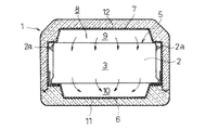
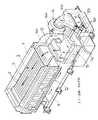
図1〜図4において、1は、ハイブリッド車を含む電気自動車用の駆動電源としての電池パックで、10〜30個の扁平な角形の二次電池2を、その長側面間に熱媒体通路3をあけて並列配置し、並列方向の両端に配設した一対の端板4で挟持し、拘束部材(図示せず)にて一体的に固定して構成された電池組立体5を内蔵している。各二次電池2は、長側面の長手方向に複数の単電池(図示せず)を並列配置するとともに単電池同士を直列接続し、両端に外部との接続端子2aが突設された電池モジュールとして構成され、電池組立体5はこれらの二次電池2の両端の接続端子2aをバス・バー(図示せず)にて順次直列に接続することで所定の出力電圧を得ている。
【0026】
電池組立体5は、二次電池2の長手方向両端部を下部ケース6にて支持した状態で、下部ケース6と上部ケース7にて覆われた収容空間8内に収容配置されている。電池組立体5の上面と上部ケース7の間には熱媒体を熱媒体通路3に送給する送給通路9が形成され、電池組立体5の下面と下部ケース6の間には熱媒体を熱媒体通路3から排出される排出通路10が形成されている。また、下部ケース6と上部ケース7の外面にはそれぞれ、発泡合成樹脂製の断熱材から成る下部断熱カバー11と上部断熱カバー12が装着されている。また、これら断熱カバー11、12の外面にはアルミ箔などの金属箔表皮が装着されている。
【0027】
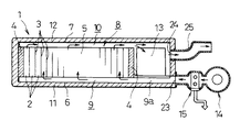
上部ケース7及び下部ケース6は、電池組立体5の配置部の一側方に延出されており、各二次電池2に対する充放電を制御する制御部ユニット13と熱媒体を送給する送給手段14と熱媒体を加熱又は冷却する加熱・冷却手段15が収容配置されている。なお、下部ケース6の一側方への延出部には、電池組立体5の下部の排出通路10に接続された排出通路10aが形成され、下部ケース6の端部で上面に排出口10bが開口されている。
【0028】
送給手段14は、ファン14aと、排出口10bとファン14aの吸入側を接続する吸入ダクト14bと、送給通路9とファン14aの吐出側を接続する送給ダクト14cを備えており、加熱・冷却手段15はファン14aの吐出口と送給ダクト14cとの間に配設されている。
【0029】
加熱・冷却手段15は、図5に示すように、車両の冷却水を導入循環させて熱媒体を冷却する熱交換器16と、結露水を捕集して排出する保護ネット17と、PTCヒータ、ペルチェ素子などを用いた加熱手段18にて構成されている。16aは熱交換器16に対して冷却水を給排する給排管、17aは保護ネット17で捕集された結露水を外部に排出するドレイン通路である。
【0030】
また、上部ケース7には、制御部ユニット13の近傍上方部分に上方に膨出する膨出空間19が形成され、かつその上端部を外部に開放する比較的小さな開口面積の開放口20が形成され、上部断熱カバー12には膨出空間部19が嵌入するとともに開放口20を外部に連通させる開口19aが形成されている。
【0031】
以上の構成によれば、加熱・冷却手段15にて所定温度に温度調整した熱媒体を送給手段14にて送給通路9を介して電池組立体5における二次電池2、2間の熱媒体通路3に流通させ、排出通路10を介して送給手段14に還流させて循環させると、各二次電池2の略全面で熱媒体と熱交換されるので、電池組立体5の全体をコンパクトで安価な構成にて格段に効率的に所定温度に制御できる。かくして、電池組立体5をその温度状態に応じて加熱または冷却することにより、電池出力を安定して得ることができるとともに、電池寿命を向上することができる。
【0032】
しかも、その電池組立体5、送給通路9、及び排出通路10を配置した収容空間8を断熱カバー11、12で覆っているため、収容空間8と外部との間の熱伝達を抑制でき、さらに断熱カバー11、12の外面に金属箔からなる表皮を設けて熱線を反射させるようにしているので、外部への熱の逃出を防止できるとともに外部からの輻射熱や環境雰囲気からの熱伝達を効果的に防止できて高い熱効率が得られる。したがって、環境条件に左右されることなく、電池組立体5の全体を所定温度に効率的にかつ均一に制御することができ、温度上昇及び温度ばらつきを低減して電池寿命を向上することができる。
【0033】
また、加熱・冷却手段15の冷却手段として、車両等で用いられている冷却媒体を流通させて熱媒体を冷却する熱交換器16を適用しているので、車両等で用いられている冷却媒体を利用して、熱効率良く熱媒体を冷却して低温の熱媒体を得ることができる。
【0034】
また、制御部ユニット13を電池組立体5の一側部に配置し、断熱カバー11、12で覆われた収容空間8内に収容しているので、制御部ユニット13の温度も所定温度に制御できてその作動安定性を確保できるとともに、制御部ユニット13が一体的に内蔵された電池パック1が構成され、安全性が高く、取扱いの容易な電池パック1が得られる。その際に、制御部ユニット13の近傍の上方部に上方に膨出する膨出空間19を設け、この膨出空間19の上端部を開放口20にて外部に開放しているので、閉鎖された同一の収容空間8内に電池組立体5と制御部ユニット13を配置しても、電池組立体5から流出した水素ガスなどの軽いガスは膨出空間19に溜まって開放口20から外部に放出されるので、制御部ユニット13にガスが流れて点火したり、悪影響を与えたりする恐れを無くして、安全性を確保できる。
【0035】
さらに、閉鎖された同一の収容空間8内に加熱・冷却手段15も収容配置し、送給手段14の吐出側を加熱・冷却手段15を介して送給通路9に接続しているので、熱媒体を閉サイクルで循環させて温度調整する温度調整機能を内蔵した電池パック1が構成され、電池組立体5を外部の環境条件に左右されずに一層安定的に所定温度に維持できるとともに、取扱いの容易な電池パックが得られる。また、電池パック1の全体が断熱カバー11、12で覆われているので、外部への騒音を低減することができる。また、その際に冷却手段としての熱交換器16で発生した結露水を保護ネット17で捕集してドレイン通路17aにて収容空間8外に排出するようにしているので、結露水を円滑に外部に排出でき、熱媒体を閉サイクルで循環させる収容空間8の雰囲気を良好に保つことができる。
【0036】
以上の説明では、送給ダクト14cが合成樹脂製又は金属製のダクトから成るものを例示したが、この電池パック1を高温多湿環境に長期間放置した後作動を開始した場合、収容空間8の雰囲気がそれよりもかなり高温多湿になっているため、送給ダクト14cには冷却された熱媒体が流通すると送給ダクト14cの外面に結露し、その結露水が制御部ユニット13上に滴下して悪影響を与える恐れかある。そこで、図6(a)に示すように、送給ダクト14cの外面に高分子吸収シート21を貼付けておくのが好適である。また、図6(b)に示すように、送給ダクト14cを断熱材22にて構成しても良い。また、吸入ダクト14bが制御部ユニット13上に配設される場合には、この吸入ダクト14bに同様の手段を講ずるのが好適である。
【0037】
また、上記の説明では、送給手段の吐出側を送給通路に加熱・冷却手段を介して接続した例を示したが、送給手段の吸込側を排出通路に加熱・冷却手段を介して接続しても良い。
【0038】
(第2の実施形態)
次に、本発明の電池パックの第2の実施形態について、図7を参照して説明する。なお、以下の実施形態の説明では、先行する実施形態と同一の構成要素については同一の参照符号を付して説明を省略し、相違点についてのみ説明する。
【0039】
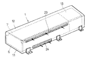
上記第1の実施形態では、断熱カバー11、12で覆われた収容空間8内に、送給手段14及び加熱・冷却手段15も収容配置した例を示したが、本実施形態では下部ケース6及び上部ケース7にて形成された収容空間8内に、電池組立体5と制御部ユニット13を配設し、送給手段14及び加熱・冷却手段15は外部に配設している。また、下部ケース6と電池組立体5の下面の間に送給空間9を、上部ケース7と電池組立体5の上面の間に排出空間10を形成し、電池組立体5の熱媒体通路3を下から上に向けて熱媒体が流通するように構成している。23は、収容空間8の下部に設けられた熱媒体の導入口であり、下部ケース6の延出部に形成された送給通路9aを介して送給通路9に接続されている。24は収容空間8の上部に設けられた熱交換後の熱媒体の排出口であり、排出管25が接続されている。
【0040】
以上の構成によれば、送給手段14及び加熱・冷却手段15を電池パック1の外部に配設しているので、その分コンパクトな構成となり、設置スペースの自由度が高く、また車両等に搭載されている別の送給手段や熱媒体供給手段を利用することができる。
【0041】
(第3の実施形態)
次に、本発明の電池パックの第3の実施形態について、図8を参照して説明する。
【0042】
本実施形態では、上記第2の実施形態の導入口23及び排出口24を、収容空間8の電池組立体5の長手方向と平行な側面に形成している。また、収容空間8の上部に導入口23を、下部に排出口24を形成し、第1の実施形態と同様に電池組立体5の上部に送給通路9を、下部に排出通路10を配設し、熱媒体通路3に上方から下方に熱媒体を流すように構成されている。
【0043】
本実施形態の電池パック1は、電池パック1の長手方向の寸法に制限がある場合に好適に適用できる。
【0044】
(第4の実施形態)
次に、本発明の電池パックの第4の実施形態について、図9を参照して説明する。
【0045】
本実施形態では、下部ケース6と上部ケース7にて形成され、断熱カバー11、12で覆われた収容空間8内に、電池組立体5を配設し、送給通路9の入口の導入口23と排出通路10の出口の排出口24に弁部材26を配設している。この弁部材26は、実線で示すように熱媒体を流通させると、熱媒体の流動方向に開放可能で、かつ常時は仮想線で示すように閉鎖位置に向けて付勢されるように構成されている。また、上部ケース7の上端部の適所に、上部断熱カバー12を貫通して外部に開放される開口27を形成するとともに、その内部に連続気泡を有するスポンジ等など、ガスを外部に逃がすことができるガス逃がし通路形成部材28を配置している。
【0046】
以上の構成によれば、弁部材26を設けたことにより、熱媒体が送給されている間は流量を確保でき、運転停止時には送給通路9と排出通路10の出入口が閉鎖されることで、温度調整された熱媒体が断熱カバー11、12にて外部に対して断熱された状態で閉じ込められるので、電池組立体5の温度が外部からの熱影響を受けて高温になったり、過冷却されるのを防止でき、電池寿命を向上できるとともに低温下での出力低下を抑制することができる。また、電池組立体5の任意の二次電池2から流出した水素ガスやアルカリミストが排出通路10と送給通路9の外部に流出するのを抑制でき、周囲の機器に悪影響を与えるのを防止できる。また、ガス逃がし通路形成部材28から収容空間8内の水素ガスが安全に外部に排出されるので、水素ガス濃度が高くなるのを防止でき、上記効果を奏しながら安全性を確保することができる。
【0047】
なお、本実施形態の弁部材26やガス逃がし通路形成部材28の配置構成は、本実施形態に限らず第1〜第3の実施形態にも適用することができ、適用することで同様の作用効果を奏することができる。
【0048】
【発明の効果】
本発明の電池パックによれば、複数の二次電池から成る電池組立体の各二次電池間の熱媒体通路に熱媒体を流通させることで各二次電池が略全面で熱交換されてその温度制御を効率的かつ均一に行うことができ、かつ電池組立体の周囲を断熱カバーで覆っているため、外部への熱の逃出を防止できるとともに外部からの輻射熱や環境雰囲気からの熱伝達も防止できて高い熱効率が得られ、環境条件に左右されることなく、電池組立体の全体を所定温度に効率的にかつ均一に制御することができ、温度上昇及び温度ばらつきを低減して電池寿命を向上することができる。
【図面の簡単な説明】
【図1】本発明の電池パックの第1の実施形態の縦断正面図である。
【図2】図1のA−A矢視縦断面図である。
【図3】同実施形態の断熱カバーを除去した状態の透視斜視図である。
【図4】同実施形態の分解斜視図である。
【図5】同実施形態における送給手段と加熱・冷却手段の斜視図である。
【図6】同実施形態の送給ダクトの変形例を示し、(a)は第1の変形例の断面図、(b)は第2の変形例の断面図である。
【図7】本発明の電池パックの第2の実施形態の縦断正面図である。
【図8】本発明の電池パックの第3の実施形態の要部の斜視図である。
【図9】本発明の電池パックの第4の実施形態の縦断正面図である。
【符号の説明】
1 電池パック
2 二次電池
3 熱媒体通路
5 電池組立体
6 下部ケース
7 上部ケース
9 送給通路
10 排出通路
11 下部断熱カバー
12 上部断熱カバー
13 制御部ユニット(充放電制御部)
14 送給手段
14b 吸入ダクト
14c 送給ダクト
15 加熱・冷却手段
16 熱交換器(冷却手段)
17a ドレイン通路
18 加熱手段
19 膨出空間
20 開放口
21 高分子吸収シート
22 断熱材
26 弁部材
28 ガス逃がし通路形成部材[0001]
BACKGROUND OF THE INVENTION
The present invention relates to a battery pack in which the temperature of each secondary battery in a battery assembly composed of a plurality of secondary batteries can be stably and uniformly controlled to a predetermined temperature.
[0002]
[Prior art]
Conventionally, in a battery assembly composed of a plurality of secondary batteries, in order to prevent the secondary battery temperature from rising due to heat generated by charging / discharging and reducing the battery output, charging / discharging efficiency and battery life, It is known that the secondary batteries are arranged in parallel via a cooling medium passage for passing the cooling medium between them, and provided with cooling medium feeding means for feeding the cooling medium toward the cooling medium path (for example, (See Patent Document 1).
[0003]
Further, a battery assembly in which four of the six side surfaces are insulated with a heat insulating material and the remaining two side surfaces are cooled (for example, see Patent Document 2).
[0004]
In addition, a container for housing a plurality of secondary batteries in contact with the peripheral surface and being thermally coupled is provided, the outer periphery of the container is covered with a heat insulating material, and the container is disposed on the wall surface of the container. What is provided with the heat pipe which discharge | releases the transmitted heat to the exterior is known (for example, refer patent document 3).
[0005]
[Patent Document 1]
JP-A-2001-167803 [0006]
[Patent Document 2]
JP-A-7-192774 [0007]
[Patent Document 3]
Japanese Patent Laid-Open No. 2001-76771
[Problems to be solved by the invention]
By the way, in the configuration disclosed in
[0009]
Further, in the configuration as disclosed in
[0010]
Further, in the configuration as disclosed in
[0011]
In view of the above-described conventional problems, an object of the present invention is to provide a battery pack capable of stably and uniformly controlling the temperature of each secondary battery in a battery assembly including a plurality of secondary batteries to a predetermined temperature. To do.
[0012]
[Means for Solving the Problems]
The battery pack according to the present invention includes a battery assembly in which a plurality of secondary batteries are arranged in parallel with a heat medium passage through which a heat medium is passed, and a supply that discharges the heat medium toward the heat medium passage. A heat insulating cover made of a heat insulating material that covers a substantially entire surface around the battery assembly by opening a supply passage and a discharge passage between the battery assembly, a feeding means for feeding a heat medium to the feeding passage, and a heat medium A heating means and a heating / cooling means having a cooling means for cooling the heat medium , the feeding means and the heating / cooling means are arranged on one side of the battery assembly and accommodated in the heat insulating cover, Connect the discharge side of the feed means to the feed passage via the heating / cooling means, or connect the suction side of the feed means to the discharge passage via the heating / cooling means, and send it to the feed passage or the discharge passage. A water absorbing sheet is disposed on the outer surface of the duct connecting the feeding means. According to the present invention , each of the secondary batteries is heat-exchanged over substantially the entire surface by circulating the heat medium through the heat medium passage between the secondary batteries, and the temperature control can be performed efficiently and uniformly. Since the assembly and the heat medium passage and the discharge passage are covered with a heat insulating cover, it is possible to prevent the escape of heat to the outside and also prevent the radiant heat from the outside and the heat transfer from the environmental atmosphere, and high thermal efficiency is obtained, The entire battery assembly can be efficiently and uniformly controlled to a predetermined temperature without being influenced by environmental conditions, and the battery life can be improved by reducing temperature rise and temperature variation.
Further, the battery assembly can be heated or cooled as necessary, so that the battery output can be stably obtained and the battery life can be improved.
In addition, a battery pack with a built-in temperature adjustment function that adjusts the temperature by circulating the heat medium in a closed cycle is configured, and the battery assembly can be maintained at a predetermined temperature more stably without being influenced by external environmental conditions. The battery pack can be easily obtained, and since the entire battery pack is covered with the heat insulating cover, noise to the outside can be reduced.
Further, even if condensation occurs on the outer surface when a cold heat medium is circulated in the duct, the condensation water can be prevented from dripping and adversely affecting the control unit or the like.
[0013]
Also, if a skin made of metal foil is provided on the outer surface of the heat insulating cover, the heat rays are reflected by the skin, so that it is possible to further prevent internal heat from escaping to the outside and radiant heat and heat transfer from the outside. Therefore, the temperature can be controlled more efficiently.
[0015]
In addition, when the cooling means includes a heat exchanger that circulates the cooling medium and cools the heat medium, the cooling medium is cooled efficiently by using the cooling medium used in the vehicle or the like. Can be obtained.
[0016]
Further, when the heating means is composed of a PTC heater or a Peltier element for heating the heat medium, a high-temperature heat medium can be easily obtained.
[0017]
In addition, if a valve member that is constantly urged toward the closed position so as to be openable in the flow direction of the heat medium is provided at the entrance and exit of the discharge passage and the feed passage, the flow rate is maintained while the heat medium is being fed. When the operation is stopped, the outlet and outlet of the discharge passage and the supply passage are closed, so that the temperature-adjusted heat medium is confined to the outside by the heat insulation cover. Can be prevented from being heated to a high temperature or being supercooled due to the influence of heat from the outside, and the battery life can be improved and a decrease in output at a low temperature can be suppressed. In addition, hydrogen gas and alkali mist flowing out from the secondary battery can be prevented from flowing out of the discharge passage and the supply passage, and adverse effects on surrounding devices can be prevented.
[0018]
In addition, if a gas escape passage is provided at the upper end of the space in the heat insulating cover closed by the valve member, the hydrogen gas in the space in the heat insulating cover can be safely discharged outside to increase the hydrogen gas concentration. Safety can be ensured while exhibiting the above effects.
[0019]
In addition, when the charge / discharge control unit of the secondary battery is arranged on one side of the battery assembly and accommodated in the heat insulating cover, a battery pack in which the charge / discharge control unit is also integrated is configured, and the safety is high. A battery pack that is easy to handle can be obtained.
[0020]
In addition, if a bulging space that bulges upward is provided in the upper part in the vicinity of the charge / discharge control unit in the internal space surrounded by the heat insulating cover, and an open port that opens the upper end of the bulging space to the outside is provided, the battery Light gas such as hydrogen gas that has flowed out of the assembly accumulates in the expansion space and is released from the open port, so there is no risk of gas flowing into the charge / discharge control unit and igniting or adversely affecting it. Can be secured.
[0022]
In addition, if a drain passage is provided to discharge the condensed water generated by the cooling means to the outside of the heat insulating cover, the condensed water can be discharged smoothly and the atmosphere of the internal space in which the heat medium is circulated in a closed cycle can be kept good. it can.
[0024]
DETAILED DESCRIPTION OF THE INVENTION
(First embodiment)
Hereinafter, a battery pack according to a first embodiment of the present invention will be described with reference to FIGS.
[0025]
1 to 4,
[0026]
The
[0027]
The
[0028]
The feeding means 14 includes a
[0029]
As shown in FIG. 5, the heating / cooling means 15 includes a
[0030]
Further, the
[0031]
According to the above configuration, the heat medium whose temperature is adjusted to a predetermined temperature by the heating / cooling means 15 is supplied to the heat between the
[0032]
Moreover, since the
[0033]
Further, as the cooling means of the heating / cooling means 15, the
[0034]
Further, since the
[0035]
Further, the heating / cooling means 15 is also accommodated in the same
[0036]
In the above description, the
[0037]
In the above description, the discharge side of the feeding unit is connected to the feeding passage via the heating / cooling unit. However, the suction side of the feeding unit is connected to the discharge passage via the heating / cooling unit. You may connect.
[0038]
(Second Embodiment)
Next, a second embodiment of the battery pack of the present invention will be described with reference to FIG. In the following description of the embodiment, the same components as those in the preceding embodiment are denoted by the same reference numerals, description thereof will be omitted, and only differences will be described.
[0039]
In the first embodiment, an example in which the
[0040]
According to the above configuration, the
[0041]
(Third embodiment)
Next, a third embodiment of the battery pack of the present invention will be described with reference to FIG.
[0042]
In the present embodiment, the
[0043]
The
[0044]
(Fourth embodiment)
Next, a fourth embodiment of the battery pack of the present invention will be described with reference to FIG.
[0045]
In the present embodiment, the
[0046]
According to the above configuration, by providing the
[0047]
The arrangement configuration of the
[0048]
【The invention's effect】
According to the battery pack of the present invention, each of the secondary batteries is subjected to heat exchange over substantially the entire surface by circulating the heat medium through the heat medium passage between the secondary batteries of the battery assembly including a plurality of secondary batteries. Temperature control can be performed efficiently and uniformly, and the battery assembly is covered with a heat insulating cover, preventing heat from escaping to the outside, and radiant heat from outside and heat transfer from the environment The battery assembly can be controlled efficiently and uniformly at a predetermined temperature without affecting the environmental conditions, and the temperature rise and temperature variation can be reduced. Lifespan can be improved.
[Brief description of the drawings]
FIG. 1 is a longitudinal front view of a battery pack according to a first embodiment of the present invention.
FIG. 2 is a longitudinal sectional view taken along the line AA in FIG.
FIG. 3 is a see-through perspective view with the heat insulating cover of the embodiment removed.
FIG. 4 is an exploded perspective view of the same embodiment.
FIG. 5 is a perspective view of a feeding unit and a heating / cooling unit in the same embodiment.
6A and 6B show a modification of the feeding duct of the embodiment, wherein FIG. 6A is a cross-sectional view of the first modification, and FIG. 6B is a cross-sectional view of the second modification.
FIG. 7 is a longitudinal front view of a second embodiment of the battery pack of the present invention.
FIG. 8 is a perspective view of an essential part of a third embodiment of a battery pack according to the present invention.
FIG. 9 is a longitudinal front view of a battery pack according to a fourth embodiment of the present invention.
[Explanation of symbols]
DESCRIPTION OF
14 Feeding means
Claims (9)
送給手段及び加熱・冷却手段を電池組立体の一側部に配置して断熱カバー内に収容し、送給手段の吐出側を送給通路に加熱・冷却手段を介して接続するか又は送給手段の吸込側を排出通路に加熱・冷却手段を介して接続し、
送給通路又は排出通路と送給手段を接続するダクトの外面に水吸収シートを配設したことを特徴とする電池パック。A battery assembly in which a plurality of secondary batteries are arranged in parallel with a heat medium passage for passing a heat medium therebetween, and a supply passage and a discharge passage for supplying and discharging the heat medium toward the heat medium passage A heat insulating cover made of a heat insulating material that covers the entire surface of the battery assembly and is opened between the battery assembly, a feeding unit that feeds the heat medium to the feeding passage, a heating unit that heats the heat medium, and heat A heating / cooling means having a cooling means for cooling the medium ,
The feeding means and the heating / cooling means are arranged on one side of the battery assembly and accommodated in the heat insulating cover, and the discharge side of the feeding means is connected to the feeding passage via the heating / cooling means, or is fed. Connect the suction side of the supply means to the discharge passage via heating / cooling means,
A battery pack comprising a water absorbing sheet disposed on an outer surface of a duct connecting a feeding passage or a discharging passage and a feeding means .
Priority Applications (2)
| Application Number | Priority Date | Filing Date | Title |
|---|---|---|---|
| JP2003080874A JP4366100B2 (en) | 2003-03-24 | 2003-03-24 | Battery pack |
| US10/806,116 US7230404B2 (en) | 2003-03-24 | 2004-03-23 | Battery pack apparatus with heat supply and discharge |
Applications Claiming Priority (1)
| Application Number | Priority Date | Filing Date | Title |
|---|---|---|---|
| JP2003080874A JP4366100B2 (en) | 2003-03-24 | 2003-03-24 | Battery pack |
Publications (2)
| Publication Number | Publication Date |
|---|---|
| JP2004288527A JP2004288527A (en) | 2004-10-14 |
| JP4366100B2 true JP4366100B2 (en) | 2009-11-18 |
Family
ID=33294613
Family Applications (1)
| Application Number | Title | Priority Date | Filing Date |
|---|---|---|---|
| JP2003080874A Expired - Lifetime JP4366100B2 (en) | 2003-03-24 | 2003-03-24 | Battery pack |
Country Status (2)
| Country | Link |
|---|---|
| US (1) | US7230404B2 (en) |
| JP (1) | JP4366100B2 (en) |
Families Citing this family (105)
| Publication number | Priority date | Publication date | Assignee | Title |
|---|---|---|---|---|
| KR100853621B1 (en) * | 2004-10-26 | 2008-08-25 | 주식회사 엘지화학 | Battery pack cooling system |
| JP5000851B2 (en) * | 2005-02-16 | 2012-08-15 | プライムアースEvエナジー株式会社 | Fan structure and battery pack |
| US8062780B2 (en) | 2005-03-17 | 2011-11-22 | Nec Corporation | Film-covered electric device and method of manufacturing same |
| US7743614B2 (en) | 2005-04-08 | 2010-06-29 | Bsst Llc | Thermoelectric-based heating and cooling system |
| US20060261783A1 (en) * | 2005-05-23 | 2006-11-23 | Paul Gamboa | Electronic battery module (EBM) with bidirectional DC-DC converter |
| JP5253711B2 (en) * | 2005-06-02 | 2013-07-31 | 本田技研工業株式会社 | Battery cooling structure |
| US9017847B2 (en) | 2005-06-17 | 2015-04-28 | Nec Corporation | Electric device assembly and film-covered electric device structure |
| KR100932214B1 (en) * | 2005-10-14 | 2009-12-16 | 주식회사 엘지화학 | Heat exchange system of battery pack using thermoelectric elements |
| KR100937903B1 (en) * | 2005-11-03 | 2010-01-21 | 주식회사 엘지화학 | Sealed heat exchange system of battery pack |
| JP5046516B2 (en) * | 2005-12-20 | 2012-10-10 | プライムアースEvエナジー株式会社 | Battery pack |
| WO2007077666A1 (en) | 2005-12-28 | 2007-07-12 | Nec Corporation | Field effect transistor, and multilayered epitaxial film for use in preparation of field effect transistor |
| CA2538817C (en) * | 2006-03-08 | 2010-05-18 | Psion Teklogix Inc. | Insulated smart battery pack for low temperature applications |
| US7576513B1 (en) * | 2006-04-26 | 2009-08-18 | Nierescher David S | Battery charger configuration reducing thermal conduction |
| JP4839955B2 (en) * | 2006-05-11 | 2011-12-21 | トヨタ自動車株式会社 | Battery pack and vehicle |
| JP5145663B2 (en) * | 2006-07-05 | 2013-02-20 | トヨタ自動車株式会社 | Secondary battery ventilation channel and secondary battery temperature control device |
| US20100155018A1 (en) | 2008-12-19 | 2010-06-24 | Lakhi Nandlal Goenka | Hvac system for a hybrid vehicle |
| JP4960042B2 (en) * | 2006-08-28 | 2012-06-27 | プライムアースEvエナジー株式会社 | Battery assembly with heater |
| JP5090070B2 (en) * | 2006-10-06 | 2012-12-05 | プライムアースEvエナジー株式会社 | Battery pack |
| US8127876B2 (en) * | 2006-10-26 | 2012-03-06 | Deere & Company | Cooling enclosure for electronic motor control components |
| JP4811240B2 (en) | 2006-11-15 | 2011-11-09 | トヨタ自動車株式会社 | Power supply |
| KR100942985B1 (en) * | 2007-03-21 | 2010-02-17 | 주식회사 엘지화학 | Medium and large battery pack case with improved distribution uniformity of refrigerant flow rate |
| JP5088071B2 (en) * | 2007-09-28 | 2012-12-05 | 三菱自動車工業株式会社 | Battery unit for electric vehicles |
| JP2009227121A (en) * | 2008-03-24 | 2009-10-08 | Sanyo Electric Co Ltd | Battery unit |
| KR101053267B1 (en) * | 2008-06-11 | 2011-08-01 | 주식회사 엘지화학 | U-type battery pack for electric vehicles |
| JP2010040420A (en) * | 2008-08-07 | 2010-02-18 | Sanyo Electric Co Ltd | Power source device for vehicle |
| US8153290B2 (en) * | 2008-10-28 | 2012-04-10 | Tesla Motors, Inc. | Heat dissipation for large battery packs |
| JP5768994B2 (en) * | 2008-11-17 | 2015-08-26 | カルソニックカンセイ株式会社 | Battery cooling system for vehicles |
| DE102009029629B4 (en) * | 2008-12-15 | 2025-06-18 | Hanon Systems | Heat exchangers for temperature control of vehicle batteries |
| WO2010135371A2 (en) | 2009-05-18 | 2010-11-25 | Bsst Llc | Battery thermal management system |
| JP5586202B2 (en) * | 2009-10-06 | 2014-09-10 | 株式会社東芝 | Secondary battery module |
| JP5477571B2 (en) * | 2009-12-24 | 2014-04-23 | 三菱自動車工業株式会社 | Battery pack cooling structure |
| JP5433427B2 (en) * | 2010-01-04 | 2014-03-05 | 三菱重工業株式会社 | Battery pack |
| DE102010011983A1 (en) * | 2010-03-19 | 2011-09-22 | Li-Tec Battery Gmbh | Battery housing for receiving electrochemical energy storage cells |
| JP5464357B2 (en) * | 2010-03-23 | 2014-04-09 | 三菱自動車工業株式会社 | Automotive battery pack |
| JP2011253746A (en) * | 2010-06-03 | 2011-12-15 | Nippon Telegr & Teleph Corp <Ntt> | Storage battery module and storage battery system |
| US8353315B2 (en) | 2010-08-23 | 2013-01-15 | Lg Chem, Ltd. | End cap |
| US8920956B2 (en) | 2010-08-23 | 2014-12-30 | Lg Chem, Ltd. | Battery system and manifold assembly having a manifold member and a connecting fitting |
| US8469404B2 (en) | 2010-08-23 | 2013-06-25 | Lg Chem, Ltd. | Connecting assembly |
| US8758922B2 (en) | 2010-08-23 | 2014-06-24 | Lg Chem, Ltd. | Battery system and manifold assembly with two manifold members removably coupled together |
| JP5198522B2 (en) * | 2010-08-31 | 2013-05-15 | トヨタ自動車株式会社 | Power storage device and vehicle |
| EP2456003A1 (en) * | 2010-11-22 | 2012-05-23 | Saab Automobile Ab | Battery Pack |
| EP2485321B1 (en) * | 2011-02-04 | 2016-10-19 | Sony Ericsson Mobile Communications AB | Electrical connector comprising a temperature control arrangement |
| DE102011077924A1 (en) | 2011-06-21 | 2012-12-27 | Robert Bosch Gmbh | Storage unit for storing electrical energy with a heat pipe |
| AT511669B1 (en) * | 2011-06-30 | 2015-06-15 | Avl List Gmbh | RECHARGEABLE ELECTRIC BATTERY |
| WO2013009759A2 (en) | 2011-07-11 | 2013-01-17 | Amerigon Incorporated | Thermoelectric-based thermal management of electrical devices |
| JP5472493B2 (en) * | 2011-08-31 | 2014-04-16 | トヨタ自動車株式会社 | Busbar module, vehicle power supply device and vehicle |
| EP2787572B1 (en) * | 2011-11-30 | 2016-12-28 | Valeo Japan Co., Ltd. | Battery temperature control unit |
| DE102012020516A1 (en) * | 2011-12-09 | 2013-06-13 | W.E.T. Automotive Systems Ag | Temperature control device for an electrochemical voltage source |
| JP5854129B2 (en) * | 2012-05-17 | 2016-02-09 | トヨタ自動車株式会社 | vehicle |
| WO2014003085A1 (en) | 2012-06-27 | 2014-01-03 | Semiconductor Energy Laboratory Co., Ltd. | Power storage unit and solar power generation unit |
| JP6035967B2 (en) * | 2012-08-03 | 2016-11-30 | スズキ株式会社 | Battery pack for vehicles |
| US8974934B2 (en) | 2012-08-16 | 2015-03-10 | Lg Chem, Ltd. | Battery module |
| AT513127B1 (en) * | 2012-08-21 | 2014-02-15 | Avl List Gmbh | Electric energy storage |
| KR101371739B1 (en) | 2012-09-07 | 2014-03-12 | 기아자동차(주) | Battery system |
| US9793525B2 (en) | 2012-10-09 | 2017-10-17 | Johnson Battery Technologies, Inc. | Solid-state battery electrodes |
| JP6220549B2 (en) * | 2012-10-24 | 2017-10-25 | 株式会社ヴァレオジャパン | Battery temperature adjustment unit and battery module using the same |
| CN104756305B (en) * | 2012-11-05 | 2016-07-20 | 日产自动车株式会社 | Battery temperature control device |
| US20140190568A1 (en) * | 2013-01-08 | 2014-07-10 | GM Global Technology Operations LLC | Coolant Activated Rechargeable Energy Storage System Drain Plug |
| WO2014110524A1 (en) | 2013-01-14 | 2014-07-17 | Gentherm Incorporated | Thermoelectric-based thermal management of electrical devices |
| JP6637765B2 (en) | 2013-01-30 | 2020-01-29 | ジェンサーム インコーポレイテッドGentherm Incorporated | Thermoelectric based thermal management system |
| US9337680B2 (en) * | 2013-03-12 | 2016-05-10 | Ford Global Technologies, Llc | Method and system for controlling an electric vehicle while charging |
| JP5842867B2 (en) | 2013-06-03 | 2016-01-13 | 株式会社デンソー | Battery cooling device |
| JP5942960B2 (en) * | 2013-06-04 | 2016-06-29 | 株式会社デンソー | Calorific value control device |
| JP5846166B2 (en) * | 2013-07-29 | 2016-01-20 | 株式会社デンソー | Battery pack |
| JP6149610B2 (en) * | 2013-08-28 | 2017-06-21 | 株式会社デンソー | Battery cooling device |
| US9067486B2 (en) * | 2013-08-30 | 2015-06-30 | Ford Global Technologies, Llc | Air cooling system for high voltage battery cell arrays |
| DE102013219969A1 (en) * | 2013-10-01 | 2015-04-02 | Continental Automotive Gmbh | Housing for electrical and electronic vehicle components, vehicle battery and power electronics or control electronics module |
| JP6146252B2 (en) * | 2013-10-15 | 2017-06-14 | 株式会社デンソー | Battery pack |
| JP6391583B2 (en) * | 2013-10-17 | 2018-09-19 | 日本碍子株式会社 | Secondary battery |
| CN106030898B (en) | 2013-10-29 | 2019-04-05 | 詹思姆公司 | Battery Thermal Management Using Thermoelectrics |
| JP6156065B2 (en) * | 2013-10-31 | 2017-07-05 | トヨタ自動車株式会社 | Battery cooling structure |
| JP6167933B2 (en) * | 2014-02-24 | 2017-07-26 | 株式会社デンソー | Battery pack |
| US10118502B2 (en) * | 2014-06-11 | 2018-11-06 | Panasonic Intellectual Property Management Co., Ltd. | Temperature conditioning unit, temperature conditioning system, and vehicle provided with temperature conditioning unit |
| US9666915B2 (en) * | 2014-06-11 | 2017-05-30 | Enovate Medical, Llc | Transfer priority for a wireless transfer station |
| JP6401944B2 (en) * | 2014-06-18 | 2018-10-10 | 近畿車輌株式会社 | Railway vehicle |
| DE102014215550A1 (en) * | 2014-08-06 | 2016-02-11 | Robert Bosch Gmbh | Electrical energy storage module and corresponding modular energy storage |
| KR102226353B1 (en) | 2014-09-12 | 2021-03-10 | 젠썸 인코포레이티드 | Graphite thermoelectric and/or resistive thermal management systems and methods |
| JP2016105365A (en) * | 2014-12-01 | 2016-06-09 | マツダ株式会社 | Battery protection device of vehicle |
| US9954260B2 (en) | 2015-03-16 | 2018-04-24 | Thunder Power New Energy Vehicle Development Company Limited | Battery system with heat exchange device |
| US10703211B2 (en) | 2015-03-16 | 2020-07-07 | Thunder Power New Energy Vehicle Development Company Limited | Battery pack, battery charging station, and charging method |
| US9550406B2 (en) | 2015-03-16 | 2017-01-24 | Thunder Power Hong Kong Ltd. | Thermal dissipation system of an electric vehicle |
| US10173687B2 (en) | 2015-03-16 | 2019-01-08 | Wellen Sham | Method for recognizing vehicle driver and determining whether driver can start vehicle |
| CN107615566B (en) | 2015-09-14 | 2021-02-05 | 松下知识产权经营株式会社 | Temperature adjusting unit, temperature adjusting system and vehicle |
| EP3742519A1 (en) | 2015-12-15 | 2020-11-25 | Apple Inc. | Microporous insulators |
| JP6763965B2 (en) | 2015-12-21 | 2020-09-30 | ジョンソン・アイピー・ホールディング・エルエルシー | Solid-state batteries, separators, electrodes and manufacturing methods |
| US10218044B2 (en) | 2016-01-22 | 2019-02-26 | Johnson Ip Holding, Llc | Johnson lithium oxygen electrochemical engine |
| US10828974B2 (en) * | 2016-04-04 | 2020-11-10 | The Raymond Corporation | Energy source enclosure systems and methods with through-air thermal management |
| US10272758B2 (en) | 2016-11-02 | 2019-04-30 | Proterra Inc. | Battery system of an electric vehicle |
| US10756401B2 (en) | 2017-02-08 | 2020-08-25 | Denso Corporation | Power source apparatus and work machine having the same |
| US10818903B1 (en) | 2017-08-15 | 2020-10-27 | Apple Inc. | Polypropylene carbonate and catalysts |
| JP7153834B2 (en) * | 2018-03-08 | 2022-10-17 | パナソニックIpマネジメント株式会社 | Temperature conditioning unit |
| US10873116B2 (en) * | 2018-05-18 | 2020-12-22 | Lee Fei Chen | Charging device having thermoelectric module |
| US11993132B2 (en) | 2018-11-30 | 2024-05-28 | Gentherm Incorporated | Thermoelectric conditioning system and methods |
| CN109638385A (en) * | 2019-01-22 | 2019-04-16 | 海口博澳国兴新能源科技有限公司 | Lithium-ion battery systems and lithium ion battery temprature control method |
| US11152557B2 (en) | 2019-02-20 | 2021-10-19 | Gentherm Incorporated | Thermoelectric module with integrated printed circuit board |
| DE102019120031A1 (en) | 2019-07-24 | 2021-01-28 | Elringklinger Ag | Control device |
| US11850970B2 (en) * | 2019-08-18 | 2023-12-26 | Board Of Regents, The University Of Texas System | J-type air-cooled battery thermal management system and method |
| JP7490964B2 (en) * | 2020-01-23 | 2024-05-28 | 三菱自動車工業株式会社 | battery pack |
| CN216850070U (en) * | 2021-11-29 | 2022-06-28 | 宁德时代新能源科技股份有限公司 | Charging devices and electrical equipment |
| US12249857B2 (en) | 2022-01-13 | 2025-03-11 | Lee Fei Chen | Electric energy management system with thermoelectric power supply conversion function |
| JP7704105B2 (en) * | 2022-08-26 | 2025-07-08 | トヨタ自動車株式会社 | Vehicle-mounted device fixing structure |
| IT202300007914A1 (en) * | 2023-04-21 | 2024-10-21 | Ferrari Spa | HEAT EXCHANGE DEVICE FOR MOTOR VEHICLE AND MOTOR VEHICLE COMPRISING THE SAME |
| US20240421407A1 (en) * | 2023-06-15 | 2024-12-19 | GM Global Technology Operations LLC | Cell stack support for a vehicle battery cell |
| CN118040154B (en) * | 2024-02-22 | 2024-08-09 | 合肥职业技术学院 | A new energy vehicle battery pack |
| CN222940014U (en) * | 2024-06-28 | 2025-06-03 | 武汉亿纬储能有限公司 | Heat exchange components, battery modules and battery packs |
Family Cites Families (6)
| Publication number | Priority date | Publication date | Assignee | Title |
|---|---|---|---|---|
| JP2001076771A (en) | 1999-09-03 | 2001-03-23 | Toshiba Battery Co Ltd | Vehicular battery pack |
| JP4543464B2 (en) | 1999-12-09 | 2010-09-15 | トヨタ自動車株式会社 | Battery pack |
| JP2001196103A (en) | 2000-01-12 | 2001-07-19 | Matsushita Electric Ind Co Ltd | Battery cooling structure |
| JP2003007356A (en) * | 2001-06-25 | 2003-01-10 | Matsushita Refrig Co Ltd | Temperature regulator for storage battery and running vehicle mounting the same |
| JP4242665B2 (en) | 2002-05-13 | 2009-03-25 | パナソニック株式会社 | Battery pack cooling device and secondary battery |
| JP4272387B2 (en) | 2002-05-22 | 2009-06-03 | パナソニック株式会社 | Battery pack cooling device |
-
2003
- 2003-03-24 JP JP2003080874A patent/JP4366100B2/en not_active Expired - Lifetime
-
2004
- 2004-03-23 US US10/806,116 patent/US7230404B2/en not_active Expired - Fee Related
Also Published As
| Publication number | Publication date |
|---|---|
| US7230404B2 (en) | 2007-06-12 |
| JP2004288527A (en) | 2004-10-14 |
| US20040232891A1 (en) | 2004-11-25 |
Similar Documents
| Publication | Publication Date | Title |
|---|---|---|
| JP4366100B2 (en) | Battery pack | |
| EP1178559B1 (en) | Battery cooling system | |
| JP5464168B2 (en) | Power supply | |
| US5730237A (en) | Battery temperature-raising device for electric vehicle | |
| CN108886189B (en) | Battery pack temperature control, power supply system | |
| JP5757502B2 (en) | Battery temperature control unit and battery temperature control device | |
| US20160049702A1 (en) | Battery pack | |
| US20130216888A1 (en) | Battery temperature regulation system and battery temperature regulation unit | |
| KR102568502B1 (en) | A Cooling Structure for cylindrical battery Cells contained cooling Fins | |
| US20100276120A1 (en) | Temperature adjusting mechanism | |
| JP5799912B2 (en) | Power supply temperature control device | |
| KR930006408A (en) | Combined thermoelectric refrigeration / heating device with thermoelectric semiconductor elements | |
| US9573217B2 (en) | Thermal control system for a hybrid welder | |
| CN109818103B (en) | Storage battery module and electric vehicle | |
| US20200313257A1 (en) | Onboard-battery temperature controller | |
| WO2018101144A1 (en) | Hot or cold storage | |
| US20250070303A1 (en) | High density cooling jacket | |
| JP2020166976A (en) | In-vehicle battery temperature control device |
Legal Events
| Date | Code | Title | Description |
|---|---|---|---|
| A621 | Written request for application examination |
Free format text: JAPANESE INTERMEDIATE CODE: A621 Effective date: 20051130 |
|
| RD03 | Notification of appointment of power of attorney |
Free format text: JAPANESE INTERMEDIATE CODE: A7423 Effective date: 20060420 |
|
| RD04 | Notification of resignation of power of attorney |
Free format text: JAPANESE INTERMEDIATE CODE: A7424 Effective date: 20060421 |
|
| A977 | Report on retrieval |
Free format text: JAPANESE INTERMEDIATE CODE: A971007 Effective date: 20070406 |
|
| A131 | Notification of reasons for refusal |
Free format text: JAPANESE INTERMEDIATE CODE: A131 Effective date: 20090519 |
|
| A521 | Request for written amendment filed |
Free format text: JAPANESE INTERMEDIATE CODE: A523 Effective date: 20090717 |
|
| TRDD | Decision of grant or rejection written | ||
| A01 | Written decision to grant a patent or to grant a registration (utility model) |
Free format text: JAPANESE INTERMEDIATE CODE: A01 Effective date: 20090811 |
|
| A01 | Written decision to grant a patent or to grant a registration (utility model) |
Free format text: JAPANESE INTERMEDIATE CODE: A01 |
|
| A61 | First payment of annual fees (during grant procedure) |
Free format text: JAPANESE INTERMEDIATE CODE: A61 Effective date: 20090824 |
|
| FPAY | Renewal fee payment (event date is renewal date of database) |
Free format text: PAYMENT UNTIL: 20120828 Year of fee payment: 3 |
|
| R150 | Certificate of patent or registration of utility model |
Free format text: JAPANESE INTERMEDIATE CODE: R150 Ref document number: 4366100 Country of ref document: JP Free format text: JAPANESE INTERMEDIATE CODE: R150 |
|
| FPAY | Renewal fee payment (event date is renewal date of database) |
Free format text: PAYMENT UNTIL: 20150828 Year of fee payment: 6 |
|
| R250 | Receipt of annual fees |
Free format text: JAPANESE INTERMEDIATE CODE: R250 |
|
| R250 | Receipt of annual fees |
Free format text: JAPANESE INTERMEDIATE CODE: R250 |
|
| R250 | Receipt of annual fees |
Free format text: JAPANESE INTERMEDIATE CODE: R250 |
|
| R250 | Receipt of annual fees |
Free format text: JAPANESE INTERMEDIATE CODE: R250 |
|
| EXPY | Cancellation because of completion of term |