EP1178559B1 - Battery cooling system - Google Patents
Battery cooling system Download PDFInfo
- Publication number
- EP1178559B1 EP1178559B1 EP20010123042 EP01123042A EP1178559B1 EP 1178559 B1 EP1178559 B1 EP 1178559B1 EP 20010123042 EP20010123042 EP 20010123042 EP 01123042 A EP01123042 A EP 01123042A EP 1178559 B1 EP1178559 B1 EP 1178559B1
- Authority
- EP
- European Patent Office
- Prior art keywords
- battery pack
- cells
- housing
- battery
- fan
- Prior art date
- Legal status (The legal status is an assumption and is not a legal conclusion. Google has not performed a legal analysis and makes no representation as to the accuracy of the status listed.)
- Expired - Lifetime
Links
Images


Classifications
-
- H—ELECTRICITY
- H02—GENERATION; CONVERSION OR DISTRIBUTION OF ELECTRIC POWER
- H02J—CIRCUIT ARRANGEMENTS OR SYSTEMS FOR SUPPLYING OR DISTRIBUTING ELECTRIC POWER; SYSTEMS FOR STORING ELECTRIC ENERGY
- H02J7/00—Circuit arrangements for charging or depolarising batteries or for supplying loads from batteries
- H02J7/0042—Circuit arrangements for charging or depolarising batteries or for supplying loads from batteries characterised by the mechanical construction
- H02J7/0044—Circuit arrangements for charging or depolarising batteries or for supplying loads from batteries characterised by the mechanical construction specially adapted for holding portable devices containing batteries
-
- B—PERFORMING OPERATIONS; TRANSPORTING
- B25—HAND TOOLS; PORTABLE POWER-DRIVEN TOOLS; MANIPULATORS
- B25F—COMBINATION OR MULTI-PURPOSE TOOLS NOT OTHERWISE PROVIDED FOR; DETAILS OR COMPONENTS OF PORTABLE POWER-DRIVEN TOOLS NOT PARTICULARLY RELATED TO THE OPERATIONS PERFORMED AND NOT OTHERWISE PROVIDED FOR
- B25F5/00—Details or components of portable power-driven tools not particularly related to the operations performed and not otherwise provided for
- B25F5/008—Cooling means
-
- H—ELECTRICITY
- H01—ELECTRIC ELEMENTS
- H01M—PROCESSES OR MEANS, e.g. BATTERIES, FOR THE DIRECT CONVERSION OF CHEMICAL ENERGY INTO ELECTRICAL ENERGY
- H01M10/00—Secondary cells; Manufacture thereof
- H01M10/42—Methods or arrangements for servicing or maintenance of secondary cells or secondary half-cells
- H01M10/46—Accumulators structurally combined with charging apparatus
-
- H—ELECTRICITY
- H01—ELECTRIC ELEMENTS
- H01M—PROCESSES OR MEANS, e.g. BATTERIES, FOR THE DIRECT CONVERSION OF CHEMICAL ENERGY INTO ELECTRICAL ENERGY
- H01M10/00—Secondary cells; Manufacture thereof
- H01M10/42—Methods or arrangements for servicing or maintenance of secondary cells or secondary half-cells
- H01M10/48—Accumulators combined with arrangements for measuring, testing or indicating the condition of cells, e.g. the level or density of the electrolyte
- H01M10/482—Accumulators combined with arrangements for measuring, testing or indicating the condition of cells, e.g. the level or density of the electrolyte for several batteries or cells simultaneously or sequentially
-
- H—ELECTRICITY
- H01—ELECTRIC ELEMENTS
- H01M—PROCESSES OR MEANS, e.g. BATTERIES, FOR THE DIRECT CONVERSION OF CHEMICAL ENERGY INTO ELECTRICAL ENERGY
- H01M10/00—Secondary cells; Manufacture thereof
- H01M10/42—Methods or arrangements for servicing or maintenance of secondary cells or secondary half-cells
- H01M10/48—Accumulators combined with arrangements for measuring, testing or indicating the condition of cells, e.g. the level or density of the electrolyte
- H01M10/486—Accumulators combined with arrangements for measuring, testing or indicating the condition of cells, e.g. the level or density of the electrolyte for measuring temperature
-
- H—ELECTRICITY
- H01—ELECTRIC ELEMENTS
- H01M—PROCESSES OR MEANS, e.g. BATTERIES, FOR THE DIRECT CONVERSION OF CHEMICAL ENERGY INTO ELECTRICAL ENERGY
- H01M10/00—Secondary cells; Manufacture thereof
- H01M10/60—Heating or cooling; Temperature control
- H01M10/61—Types of temperature control
- H01M10/613—Cooling or keeping cold
-
- H—ELECTRICITY
- H01—ELECTRIC ELEMENTS
- H01M—PROCESSES OR MEANS, e.g. BATTERIES, FOR THE DIRECT CONVERSION OF CHEMICAL ENERGY INTO ELECTRICAL ENERGY
- H01M10/00—Secondary cells; Manufacture thereof
- H01M10/60—Heating or cooling; Temperature control
- H01M10/61—Types of temperature control
- H01M10/615—Heating or keeping warm
-
- H—ELECTRICITY
- H01—ELECTRIC ELEMENTS
- H01M—PROCESSES OR MEANS, e.g. BATTERIES, FOR THE DIRECT CONVERSION OF CHEMICAL ENERGY INTO ELECTRICAL ENERGY
- H01M10/00—Secondary cells; Manufacture thereof
- H01M10/60—Heating or cooling; Temperature control
- H01M10/61—Types of temperature control
- H01M10/617—Types of temperature control for achieving uniformity or desired distribution of temperature
-
- H—ELECTRICITY
- H01—ELECTRIC ELEMENTS
- H01M—PROCESSES OR MEANS, e.g. BATTERIES, FOR THE DIRECT CONVERSION OF CHEMICAL ENERGY INTO ELECTRICAL ENERGY
- H01M10/00—Secondary cells; Manufacture thereof
- H01M10/60—Heating or cooling; Temperature control
- H01M10/62—Heating or cooling; Temperature control specially adapted for specific applications
- H01M10/623—Portable devices, e.g. mobile telephones, cameras or pacemakers
- H01M10/6235—Power tools
-
- H—ELECTRICITY
- H01—ELECTRIC ELEMENTS
- H01M—PROCESSES OR MEANS, e.g. BATTERIES, FOR THE DIRECT CONVERSION OF CHEMICAL ENERGY INTO ELECTRICAL ENERGY
- H01M10/00—Secondary cells; Manufacture thereof
- H01M10/60—Heating or cooling; Temperature control
- H01M10/63—Control systems
-
- H—ELECTRICITY
- H01—ELECTRIC ELEMENTS
- H01M—PROCESSES OR MEANS, e.g. BATTERIES, FOR THE DIRECT CONVERSION OF CHEMICAL ENERGY INTO ELECTRICAL ENERGY
- H01M10/00—Secondary cells; Manufacture thereof
- H01M10/60—Heating or cooling; Temperature control
- H01M10/64—Heating or cooling; Temperature control characterised by the shape of the cells
- H01M10/643—Cylindrical cells
-
- H—ELECTRICITY
- H01—ELECTRIC ELEMENTS
- H01M—PROCESSES OR MEANS, e.g. BATTERIES, FOR THE DIRECT CONVERSION OF CHEMICAL ENERGY INTO ELECTRICAL ENERGY
- H01M10/00—Secondary cells; Manufacture thereof
- H01M10/60—Heating or cooling; Temperature control
- H01M10/65—Means for temperature control structurally associated with the cells
- H01M10/651—Means for temperature control structurally associated with the cells characterised by parameters specified by a numeric value or mathematical formula, e.g. ratios, sizes or concentrations
- H01M10/652—Means for temperature control structurally associated with the cells characterised by parameters specified by a numeric value or mathematical formula, e.g. ratios, sizes or concentrations characterised by gradients
-
- H—ELECTRICITY
- H01—ELECTRIC ELEMENTS
- H01M—PROCESSES OR MEANS, e.g. BATTERIES, FOR THE DIRECT CONVERSION OF CHEMICAL ENERGY INTO ELECTRICAL ENERGY
- H01M10/00—Secondary cells; Manufacture thereof
- H01M10/60—Heating or cooling; Temperature control
- H01M10/65—Means for temperature control structurally associated with the cells
- H01M10/653—Means for temperature control structurally associated with the cells characterised by electrically insulating or thermally conductive materials
-
- H—ELECTRICITY
- H01—ELECTRIC ELEMENTS
- H01M—PROCESSES OR MEANS, e.g. BATTERIES, FOR THE DIRECT CONVERSION OF CHEMICAL ENERGY INTO ELECTRICAL ENERGY
- H01M10/00—Secondary cells; Manufacture thereof
- H01M10/60—Heating or cooling; Temperature control
- H01M10/65—Means for temperature control structurally associated with the cells
- H01M10/655—Solid structures for heat exchange or heat conduction
- H01M10/6551—Surfaces specially adapted for heat dissipation or radiation, e.g. fins or coatings
-
- H—ELECTRICITY
- H01—ELECTRIC ELEMENTS
- H01M—PROCESSES OR MEANS, e.g. BATTERIES, FOR THE DIRECT CONVERSION OF CHEMICAL ENERGY INTO ELECTRICAL ENERGY
- H01M10/00—Secondary cells; Manufacture thereof
- H01M10/60—Heating or cooling; Temperature control
- H01M10/65—Means for temperature control structurally associated with the cells
- H01M10/655—Solid structures for heat exchange or heat conduction
- H01M10/6554—Rods or plates
- H01M10/6555—Rods or plates arranged between the cells
-
- H—ELECTRICITY
- H01—ELECTRIC ELEMENTS
- H01M—PROCESSES OR MEANS, e.g. BATTERIES, FOR THE DIRECT CONVERSION OF CHEMICAL ENERGY INTO ELECTRICAL ENERGY
- H01M10/00—Secondary cells; Manufacture thereof
- H01M10/60—Heating or cooling; Temperature control
- H01M10/65—Means for temperature control structurally associated with the cells
- H01M10/655—Solid structures for heat exchange or heat conduction
- H01M10/6556—Solid parts with flow channel passages or pipes for heat exchange
- H01M10/6557—Solid parts with flow channel passages or pipes for heat exchange arranged between the cells
-
- H—ELECTRICITY
- H01—ELECTRIC ELEMENTS
- H01M—PROCESSES OR MEANS, e.g. BATTERIES, FOR THE DIRECT CONVERSION OF CHEMICAL ENERGY INTO ELECTRICAL ENERGY
- H01M10/00—Secondary cells; Manufacture thereof
- H01M10/60—Heating or cooling; Temperature control
- H01M10/65—Means for temperature control structurally associated with the cells
- H01M10/656—Means for temperature control structurally associated with the cells characterised by the type of heat-exchange fluid
- H01M10/6561—Gases
- H01M10/6563—Gases with forced flow, e.g. by blowers
-
- H—ELECTRICITY
- H01—ELECTRIC ELEMENTS
- H01M—PROCESSES OR MEANS, e.g. BATTERIES, FOR THE DIRECT CONVERSION OF CHEMICAL ENERGY INTO ELECTRICAL ENERGY
- H01M10/00—Secondary cells; Manufacture thereof
- H01M10/60—Heating or cooling; Temperature control
- H01M10/65—Means for temperature control structurally associated with the cells
- H01M10/656—Means for temperature control structurally associated with the cells characterised by the type of heat-exchange fluid
- H01M10/6561—Gases
- H01M10/6566—Means within the gas flow to guide the flow around one or more cells, e.g. manifolds, baffles or other barriers
-
- H—ELECTRICITY
- H01—ELECTRIC ELEMENTS
- H01M—PROCESSES OR MEANS, e.g. BATTERIES, FOR THE DIRECT CONVERSION OF CHEMICAL ENERGY INTO ELECTRICAL ENERGY
- H01M10/00—Secondary cells; Manufacture thereof
- H01M10/60—Heating or cooling; Temperature control
- H01M10/65—Means for temperature control structurally associated with the cells
- H01M10/657—Means for temperature control structurally associated with the cells by electric or electromagnetic means
- H01M10/6572—Peltier elements or thermoelectric devices
-
- H—ELECTRICITY
- H01—ELECTRIC ELEMENTS
- H01M—PROCESSES OR MEANS, e.g. BATTERIES, FOR THE DIRECT CONVERSION OF CHEMICAL ENERGY INTO ELECTRICAL ENERGY
- H01M10/00—Secondary cells; Manufacture thereof
- H01M10/60—Heating or cooling; Temperature control
- H01M10/66—Heat-exchange relationships between the cells and other systems, e.g. central heating systems or fuel cells
- H01M10/667—Heat-exchange relationships between the cells and other systems, e.g. central heating systems or fuel cells the system being an electronic component, e.g. a CPU, an inverter or a capacitor
-
- H—ELECTRICITY
- H01—ELECTRIC ELEMENTS
- H01M—PROCESSES OR MEANS, e.g. BATTERIES, FOR THE DIRECT CONVERSION OF CHEMICAL ENERGY INTO ELECTRICAL ENERGY
- H01M50/00—Constructional details or processes of manufacture of the non-active parts of electrochemical cells other than fuel cells, e.g. hybrid cells
- H01M50/20—Mountings; Secondary casings or frames; Racks, modules or packs; Suspension devices; Shock absorbers; Transport or carrying devices; Holders
- H01M50/204—Racks, modules or packs for multiple batteries or multiple cells
- H01M50/207—Racks, modules or packs for multiple batteries or multiple cells characterised by their shape
- H01M50/213—Racks, modules or packs for multiple batteries or multiple cells characterised by their shape adapted for cells having curved cross-section, e.g. round or elliptic
-
- H—ELECTRICITY
- H01—ELECTRIC ELEMENTS
- H01M—PROCESSES OR MEANS, e.g. BATTERIES, FOR THE DIRECT CONVERSION OF CHEMICAL ENERGY INTO ELECTRICAL ENERGY
- H01M50/00—Constructional details or processes of manufacture of the non-active parts of electrochemical cells other than fuel cells, e.g. hybrid cells
- H01M50/20—Mountings; Secondary casings or frames; Racks, modules or packs; Suspension devices; Shock absorbers; Transport or carrying devices; Holders
- H01M50/247—Mountings; Secondary casings or frames; Racks, modules or packs; Suspension devices; Shock absorbers; Transport or carrying devices; Holders specially adapted for portable devices, e.g. mobile phones, computers, hand tools or pacemakers
-
- H—ELECTRICITY
- H01—ELECTRIC ELEMENTS
- H01M—PROCESSES OR MEANS, e.g. BATTERIES, FOR THE DIRECT CONVERSION OF CHEMICAL ENERGY INTO ELECTRICAL ENERGY
- H01M50/00—Constructional details or processes of manufacture of the non-active parts of electrochemical cells other than fuel cells, e.g. hybrid cells
- H01M50/30—Arrangements for facilitating escape of gases
-
- H—ELECTRICITY
- H02—GENERATION; CONVERSION OR DISTRIBUTION OF ELECTRIC POWER
- H02J—CIRCUIT ARRANGEMENTS OR SYSTEMS FOR SUPPLYING OR DISTRIBUTING ELECTRIC POWER; SYSTEMS FOR STORING ELECTRIC ENERGY
- H02J7/00—Circuit arrangements for charging or depolarising batteries or for supplying loads from batteries
- H02J7/0042—Circuit arrangements for charging or depolarising batteries or for supplying loads from batteries characterised by the mechanical construction
-
- H—ELECTRICITY
- H01—ELECTRIC ELEMENTS
- H01M—PROCESSES OR MEANS, e.g. BATTERIES, FOR THE DIRECT CONVERSION OF CHEMICAL ENERGY INTO ELECTRICAL ENERGY
- H01M10/00—Secondary cells; Manufacture thereof
- H01M10/60—Heating or cooling; Temperature control
- H01M10/66—Heat-exchange relationships between the cells and other systems, e.g. central heating systems or fuel cells
-
- Y—GENERAL TAGGING OF NEW TECHNOLOGICAL DEVELOPMENTS; GENERAL TAGGING OF CROSS-SECTIONAL TECHNOLOGIES SPANNING OVER SEVERAL SECTIONS OF THE IPC; TECHNICAL SUBJECTS COVERED BY FORMER USPC CROSS-REFERENCE ART COLLECTIONS [XRACs] AND DIGESTS
- Y02—TECHNOLOGIES OR APPLICATIONS FOR MITIGATION OR ADAPTATION AGAINST CLIMATE CHANGE
- Y02E—REDUCTION OF GREENHOUSE GAS [GHG] EMISSIONS, RELATED TO ENERGY GENERATION, TRANSMISSION OR DISTRIBUTION
- Y02E60/00—Enabling technologies; Technologies with a potential or indirect contribution to GHG emissions mitigation
- Y02E60/10—Energy storage using batteries
-
- Y—GENERAL TAGGING OF NEW TECHNOLOGICAL DEVELOPMENTS; GENERAL TAGGING OF CROSS-SECTIONAL TECHNOLOGIES SPANNING OVER SEVERAL SECTIONS OF THE IPC; TECHNICAL SUBJECTS COVERED BY FORMER USPC CROSS-REFERENCE ART COLLECTIONS [XRACs] AND DIGESTS
- Y02—TECHNOLOGIES OR APPLICATIONS FOR MITIGATION OR ADAPTATION AGAINST CLIMATE CHANGE
- Y02P—CLIMATE CHANGE MITIGATION TECHNOLOGIES IN THE PRODUCTION OR PROCESSING OF GOODS
- Y02P70/00—Climate change mitigation technologies in the production process for final industrial or consumer products
- Y02P70/50—Manufacturing or production processes characterised by the final manufactured product
-
- Y—GENERAL TAGGING OF NEW TECHNOLOGICAL DEVELOPMENTS; GENERAL TAGGING OF CROSS-SECTIONAL TECHNOLOGIES SPANNING OVER SEVERAL SECTIONS OF THE IPC; TECHNICAL SUBJECTS COVERED BY FORMER USPC CROSS-REFERENCE ART COLLECTIONS [XRACs] AND DIGESTS
- Y10—TECHNICAL SUBJECTS COVERED BY FORMER USPC
- Y10T—TECHNICAL SUBJECTS COVERED BY FORMER US CLASSIFICATION
- Y10T29/00—Metal working
- Y10T29/49—Method of mechanical manufacture
- Y10T29/49002—Electrical device making
- Y10T29/49108—Electric battery cell making
Definitions
- the present invention relates to battery cooling systems for cordless power tools.
- Cordless power tool devices which use rechargeable batteries are prevalent throughout the workplace as well as in the home. Ordinarily, nickel-cadium or nickelmetal-hydride battery cells are used in these devices. Since the devices use a plurality of battery cells, the battery cells are ordinarily packaged as battery packs. These battery packs couple with the cordless devices and secure to the device. The battery pack may be removed from the cordless device and charged in a battery charger or charged in the cordless device itself.
- the cordless power tool device As the cordless power tool device is used, current flows through the batteries to power the cordless device. As current is drawn off the batteries, heat is generated within the battery pack. Also, during charging of the battery pack, heat is likewise accumulated during the charging process. The heat created during discharge of the batteries as well as charging of the batteries which, in turn, leads to increased temperatures, may have a severe effect on the life expectancy and performance of the batteries. In order for batteries to properly charge, the batteries must be below a desired threshold temperature and the differential temperature between the cells in the battery pack should be minimised. Likewise, if the batteries become too hot during use, battery life will be cut short. Also, if a battery is below a certain threshold temperature, it will be too cold to charge and must be warmed before charging. Thus, it is desirous to maintain batteries within a desired temperature range for optimum performance as well as optimum charging.
- battery packs typically contain some battery cells close to the outer walls of the pack, while some battery cells are surrounded by other battery cells. Those cells close to the outer walls have better thermal conductivity to the outside ambient than do the cells that are surrounded by other cells.
- the amount of heat generated is approximately the same in each cell.
- different cells will reach different temperatures.
- different cells reach different temperatures during the charging process. Accordingly, if one cell is at an increased temperature with respect to the other cells, its charge or discharge efficiency will be different, and, therefore, it may charge or discharge faster than the other cells. This will lead to a decline in the performance of the entire pack.
- DE 32 42 901 discloses a high temperature storage battery comprising a plurality of battery cells contained within a housing, a vent system comprising an inlet and an outlet for allowing the movement of cooling air around the battery pack, and a heat sink for dissipating heat from said one or more cells.
- a removable battery pack for a cordless power tool comprising:
- Said mechanism may include air directors for moving air to said one or more cells.
- the mechanism may include a fan for forcing air through said vent system to dissipate heat from the battery pack housing and the fan may be located in said battery pack housing.
- Said mechanism in said housing may be coupled with said plurality of cells for equalising temperature of said plurality of cells and said mechanism may include air directors for moving air around higher temperature cells of said one or more cells.
- a cordless power tool which comprises a tool housing including a mechanism for coupling with a removable battery pack, and a removable battery pack as described above.
- the power tool may include a battery charger for charging said battery pack, said battery charger having a mechanism for moving air through said vent system of said battery pack housing.
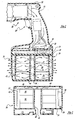
- Figure 1 is a partial cross-section view of a cordless power tool and battery in accordance with the present invention.
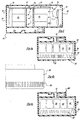
- Figure 2 is a partial cross-section view of a battery pack in accordance with the present invention.
- Figure 3 is a cross-section view of another embodiment of a battery pack in accordance with the present invention.
- Figure 4A is a cross-section view of another battery pack in accordance with the present invention.
- Figure 4B is an elevation view of the battery pack of Figure 4A.
- FIG. 4C is a cross-section view of another battery pack in accordance with the present invention.
- Figure 5 is another cross-section view of a battery pack in accordance with the present invention.
- Figure 6 is an additional cross-section view of another embodiment of a battery pack in accordance with the present invention.
- Figure 7 is an additional cross-section view of a battery pack in accordance with the present invention.
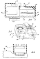
- Figure 8 is a cross-section view of an auxiliary fan module in accordance with the present invention.
- Figure 9 is a perspective view of a charger in accordance with the present invention.
- Figure 10 is a cross-section view of the auxiliary fan module coupled with the charger of Figure 9 in accordance with the present invention.
- Figure 11 is a cross-section view of another embodiment of the present invention of a charger of Figure 9.
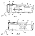
- Figure 12 is a cross-section view like that of Figure 8 of another embodiment of an auxiliary fan in accordance with the present invention.
- Figure 13 is a perspective view of a battery cooler/heater in accordance with the present invention.
- Figure 14 is a longitudinal cross-section view of Figure 13.
- Figure 15 is a view like Figure 14 of an additional embodiment of the battery cooler/heater.
- the cordless device ordinarily includes a clamshell type housing 22.
- the housing 22 includes a mechanism 24 to couple with a portion of a battery pack 26.
- the cordless device 20 includes electrical elements 28 which couple with the battery pack electrical elements 29.
- the device includes a trigger 30 which energizes the motor 32 within the housing 22.
- the battery pack 26 includes a housing 34 which contains a plurality of battery cells 36 within the housing 34. Also, the housing 34 includes a ventilation system 38 which enables fluid to pass through the housing 34 and move around the cells 36 to dissipate heat from the plurality of cells 36 to the ambient air.
- the venting system 38 ordinarily includes at least one inlet 40 and at least one outlet 42. The inlet and outlet are ordinarily apertures or slots in the housing 34.
- a channel 44 is formed within the housing 26 and aligned with the inlet 40 to distribute the fluid flow around the battery cells 36 so that all of the battery cells 36 are cooled.
- the fluid flows coaxially with respect to the axes of the batteries 36.
- the fluid is directed over the battery cells and does not pass over one cell to the next cell, etc., but is passed over a number of cells at one time so that the fluid passing through the housing is not warmed by the first cell and then passed over the second cell.
- fluid could be passed over the battery cells transversely with respect to the battery cells axes.
- the battery pack 26 is like that illustrated in Figure 1, including the housing 34, ventilation system 38 with inlet 40 and outlet 42. Also, cells 36 are positioned within the housing. Additionally, the battery pack includes one or more baffles 46, 48, 50 and 52. The baffles direct the fluid to specific battery cells 36. Ordinarily, the fluid is passed into channel 44 and distributed through the baffles 46 and 48.
- Battery pack 60 includes a housing 62 with a venting system 64 which enables fluid to pass around the battery cells 66.
- the ventilation system 64 includes at least one inlet 68 and at least one outlet 70.
- the battery housing includes a fan 72.
- the fan 72 may include a motor 74 which may run off of the battery cells 36.
- the fan motor 74 may run off of a charging circuit when the battery pack is in a charger.
- the fan 72 moves fluid through the battery pack inlet.
- the fluid is forced over the battery cells 66 and out the outlets 70.
- a positive pressure is created in the battery pack as fluid flows through the battery pack 60.
- a negative pressure could be created in the battery pack sucking fluid through the battery pack.
- the channels 73 direct the fluid through the battery cells so that the fluid does not continue to pass from cell to cell but passes over different cells so that the cells experience the air at about the same temperature.
- the battery housing may include baffles 75, 76, 77, 78 like those described above.
- an auxiliary fan could be positioned in the tool housing itself as illustrated in phantom in Figure 1 to move fluid through the battery housing. Temperature sensors may be positioned in the housing to monitor individual battery cell temperature. Also, the baffles may be designed to direct fluid flow to the hottest battery cells. Thus, the cells would be cooled as well as the temperature being equalized.
- the battery pack includes a housing 80, a plurality of cells 36 which are wrapped in a thermally conductive but electrically insulating substance 83 to remove heat from the battery pack. Also, a heat sink 84 is positioned between the cells for wicking the heat from the battery cells 36. Projecting portions 86 surround the batteries to effectively move heat towards the fins 88 of the heat sink 84. Also, a plurality of slots 90 are formed in the housing 80 to enable the heat to be removed from the battery cells 36.
- the heat sink 84 may be any type of metallic sink with the projecting portion 82 either being metallic or a thermally conductive medium, such as potting compound, gels or grease to extract the heat from the cells to the heat sink 84.
- the heat exits through the fins 88.
- more fins, as well as larger projecting portions surround battery cells which are known to have higher temperatures during charging of the battery as well as discharging when the tool is used. Thus, heat is drawn from the battery cells 36 to the heat sink.
- the ventilation slots 90 enable fluid to pass over the fins 88 to remove heat.
- an inlet 92 may be included in the housing to enable fluid to pass from a fan in the tool housing through the battery pack.
- FIG 4C illustrates an additional embodiment of the present invention.
- the battery pack is similar to that in Figures 4A and 4B, except the housing 800 does not include the plurality of slots.
- the plurality of cells 36 are wrapped in a thermally conductive but electrically insulating substance such as tape 83 to enable heat to move from battery to battery via a heat sink 84.
- the heat sink 84 is positioned between the cells to wick heat from hotter battery cells and transfer the heat to battery cells having a lower temperature so that the temperatures of the cells are equalized within the pack.
- Projecting portions 86 surround the battery cells to effectively remove heat towards the fins of the heat sink 84. Cells which are known to have higher temperatures are designated with 36 ⁇ .
- the heat sink may be a metallic type like that mentioned above, or may include thermally conductive mediums such as potting compound, gels or grease to extract heat from hotter cells and move it to the heat sink which, in turn, distributes the heat to the remaining cells such that the temperature within the cells is equalized.
- thermally conductive mediums such as potting compound, gels or grease to extract heat from hotter cells and move it to the heat sink which, in turn, distributes the heat to the remaining cells such that the temperature within the cells is equalized.
- the battery pack includes a housing 100 surrounding a plurality of cells 36.
- the housing 100 includes a plurality of slots 102 which act as outlets and an inlet 104.
- a heat pump 106 is positioned within the housing 100.
- the heat pump 100 is a Peltier device, which is commonly known in the art.
- the Peltier device is coupled with heat sinks 108 and 110, As the Peltier device is activated, one heat sink becomes cold while the other becomes hot. If the current through the Peltier device is reversed, the cold and hot sides reverse.
- the heat sinks 108, 110 can be used to provide cool air into the battery housing 100 and enable the air to be baffled by baffles 112, 114, 116 and 118 to pass over the battery cells 36 and exit the housing through the outlet slots.
- cool air would be passed into the housing to cool the batteries.
- the Peltier device current could be reversed wherein heated fluid would be passed through the battery pack to warm the battery cells so that they could be charged.
- the Peltier device is coupled to electronics 120 which may function off of the battery cells, a charger, or both, to control the cooling or heating.
- a temperature sensor 122 may be positioned in the housing, with respect to the battery cells, so that heating and cooling may take place as desired.
- Figure 6 is a view like that of Figure 5 including the heat pump 106. Additionally, a fan 124 is positioned within the housing to move the fluid through the battery pack 100. Here, fluid can be channeled throughout the battery enabling the battery to be cooled.
- a battery pack is illustrated and designated with the reference numeral 130.
- the battery pack is similar to that illustrated in Figure 4, however, a fan 132 is positioned within the battery pack. The fan 132 moves fluid across the fins 88 in an attempt to expel the heat from the battery pack housing 130.
- the auxiliary fan module 140 includes a housing 142 which houses a fan 144.
- the housing includes an inlet 146 as well as an outlet 148. Fluid flows through the outlet 148, which is surrounded by seal 149, into the battery pack inlet 40 like that illustrated in Figures 1, 2.
- Electrical contacts 150 are positioned within the housing 142 to couple with the battery electrical contacts 29 to charge the battery cells 36.
- electrical contacts 152 are secured with the housing 142 to mate with electrical contacts in a charger to run the fan during charging of the battery cells.
- an electronic package 154 is within the housing 142 to control charging of the battery as well as operation of the fan 144. The electronic package 154 may be coupled with the temperature sensor to operate the fan as needed.
- the charger 160 includes contacts 162 to couple with a battery pack or auxiliary fan module to charge a battery pack.
- the charger 160 includes a base 164 which includes the electrical contacts coupled with the base. Further a vent system 166, with inlet 167 and outlet 169, is coupled with the base 164 to enable air to pass into and through the battery charger and in turn the battery pack.
- the battery charger includes an electronics package 168 which receives the current from an AC source and converts it into the DC source required to charge the battery pack.
- the charger 160 may be utilized with the disclosed battery packs with or without fans in the battery pack.
- a battery pack which does not include a fan
- convection would be used to enable air flow through the vent system 160 and in turn through the battery pack.
- the contacts 162 would also couple with the fan electronics within the battery pack to for operating the fan.
- the electronics in the charger would electrically couple with the fan electronics to turn on and turn off the fan when needed.
- the charger could be utilized with the auxiliary fan module 140 as illustrated in Figure 10.
- the auxiliary fan module 140 is coupled with the electrical contacts 162 in the charger 160 to operate the fan 144 within the auxiliary fan module 140. Accordingly, the fan 144 may be turned on and off as desired.
- a charger 180 is shown.
- the charger 180 is similar to the battery charger 160 except that the battery charger 180 includes a fan 182 coupled with the venting system 166.
- the fan 182 moves fluid through an inlet 184 and forces the fluid through an outlet 186 into the battery pack.
- the fan 182 would be activated as desired.
- the charger electronics could be coupled with a sensor inside of the battery pack which would be activated through the electrical contacts 162. The sensor would sense the temperature within the battery pack so that the fan could run intermittently. Also, the sensors may be removed and the fan would just run constantly while the charger is operating.
- the auxiliary fan module 190 includes a fan 192, an inlet 194 and an outlet 196 in the housing 198. Also, a heat pump 200 as described above is positioned within the housing 198. The heat pump would produce a cold heat sink 202 which would enable fluid to move in to the housing, via the fan, and pass over the cold heat sink and into the battery pack. The fluid would also pass over the hot side of the heat sink 206, withdrawing heat from the housing, and exhausting the air to ambient through outlet 208. In the event the battery pack is cold, the heat pump 200 may be reversed and heat may be passed into the battery pack to warm the battery pack before charging.
- the fan module 190 also includes electrical contacts 210 to couple with the battery pack. Also, electrical contacts 212 couple with the charger 160. The electronics 214 within the auxiliary fan module 190 couple with the charger and operate the fan to move fluid into the battery pack as desired.
- Figure 13 illustrates a perspective view of a battery cooler/heater device.
- the battery cooler/heater 220 includes a housing 222.
- the housing 222 includes a battery receiving portion 224.
- the battery receiving portion 224 may be a cutout or the like in the battery housing 222 forming a depression to receive a battery housing pack.
- the housing includes an inlet 226 and an outlet 228. The inlet enables fluid to pass into a duct in the housing 222 while the outlet enables the fluid to be passed out of the housing duct and into a battery pack.
- the inlet 226 is generally covered by a filter 230 and a grill 232 is attached to the housing 222 sandwiching the filter between the inlet and the grill 232.
- the grill 232 has slots 234 to enable air to pass through the grill into the filter and turn through the inlet 226.
- An O-ring or some type of seal 236 is positioned around the outlet 228 as shown in Figure 14.
- the seal 236 mates with the battery pack to prohibit fluid from escaping around the battery pack housing while fluid is passed into the battery pack housing.
- the housing 222 includes a fan 240 to move fluid between the inlet 226 and outlet 228.
- the fan 240 is energized and de-energized by a switch 242.
- the switch 242 is a manual switch enabling the user to manually turn on and turn off the fan 240 as desired.
- a power cord 244 is coupled with the fan and switch electronics 246 to provide power to the battery cooler/heater 220.
- a Peltier device 250 (illustrated in phantom) may be positioned near the inlet which may provide cooled or heated fluid which is drawn into the battery pack as described above.
- the Peltier device 250 would be coupled with the electronics 246 so that the Peltier device 250 may deliver cold or hot fluid flow, depending upon if cooling or heating is desired, to the battery cells.
- FIG. 15 an additional embodiment of the battery heater/cooler 220 is shown.
- the battery cooler is like that described above, except that an automatic switch 260 has replaced the manual switch 242.
- the battery pack housing As the battery pack housing is slid into the battery cooler/heater housing, the battery contacts the normally open switch 260 energizing the fan 240. As the battery pack housing is withdrawn from the battery cooler/heater, the switch 260 would return to its normally open position, de-energizing the fan.
- the present invention provides the art with a battery pack which dissipates heat within the battery pack during charging of the cells as well as discharging of the cells while the battery pack is in use. Additionally, the invention provides auxiliary devices for aiding the changing of the battery pack temperature for optimizing charging of the pack. In accordance with the various aspects of the invention, the battery pack life can be increased, battery pack performance can be enhanced and charging time can be reduced.
Description
- The present invention relates to battery cooling systems for cordless power tools.
- Cordless power tool devices which use rechargeable batteries are prevalent throughout the workplace as well as in the home. Ordinarily, nickel-cadium or nickelmetal-hydride battery cells are used in these devices. Since the devices use a plurality of battery cells, the battery cells are ordinarily packaged as battery packs. These battery packs couple with the cordless devices and secure to the device. The battery pack may be removed from the cordless device and charged in a battery charger or charged in the cordless device itself.
- As the cordless power tool device is used, current flows through the batteries to power the cordless device. As current is drawn off the batteries, heat is generated within the battery pack. Also, during charging of the battery pack, heat is likewise accumulated during the charging process. The heat created during discharge of the batteries as well as charging of the batteries which, in turn, leads to increased temperatures, may have a severe effect on the life expectancy and performance of the batteries. In order for batteries to properly charge, the batteries must be below a desired threshold temperature and the differential temperature between the cells in the battery pack should be minimised. Likewise, if the batteries become too hot during use, battery life will be cut short. Also, if a battery is below a certain threshold temperature, it will be too cold to charge and must be warmed before charging. Thus, it is desirous to maintain batteries within a desired temperature range for optimum performance as well as optimum charging.
- Further, battery packs typically contain some battery cells close to the outer walls of the pack, while some battery cells are surrounded by other battery cells. Those cells close to the outer walls have better thermal conductivity to the outside ambient than do the cells that are surrounded by other cells. When a battery pack is discharging on the cordless device, the amount of heat generated is approximately the same in each cell. However, depending on the thermal path to ambient, different cells will reach different temperatures. Further, for the same reasons, different cells reach different temperatures during the charging process. Accordingly, if one cell is at an increased temperature with respect to the other cells, its charge or discharge efficiency will be different, and, therefore, it may charge or discharge faster than the other cells. This will lead to a decline in the performance of the entire pack.
-
DE 32 42 901 discloses a high temperature storage battery comprising a plurality of battery cells contained within a housing, a vent system comprising an inlet and an outlet for allowing the movement of cooling air around the battery pack, and a heat sink for dissipating heat from said one or more cells. - In accordance with a first aspect of the present invention there is provided a removable battery pack for a cordless power tool comprising:
- a housing with one or more cells in said housing; characterised by a vent system in said housing for enabling air passage through said housing; and
- a mechanism associated with said battery pack for dissipating heat in said battery pack housing, characterised in that said mechanism includes a heat sink comprising a plurality of fins for dissipating heat from said one or more cells, and said heat sink has an increased concentration of fins in the area having higher temperature cells.
- Said mechanism may include air directors for moving air to said one or more cells. The mechanism may include a fan for forcing air through said vent system to dissipate heat from the battery pack housing and the fan may be located in said battery pack housing.
- Said mechanism in said housing may be coupled with said plurality of cells for equalising temperature of said plurality of cells and said mechanism may include air directors for moving air around higher temperature cells of said one or more cells.
- According to a second aspect of the present invention there is provided a cordless power tool, which comprises a tool housing including a mechanism for coupling with a removable battery pack, and a removable battery pack as described above. The power tool may include a battery charger for charging said battery pack, said battery charger having a mechanism for moving air through said vent system of said battery pack housing.
- In accordance with further aspects of the invention, several of the above features may be combined with one another to provide additional advantages.
- Additional objects and advantages of the invention will become apparent from the detailed description of the preferred embodiment, and the appended claims and accompanying drawings, or may be learned by practice of the invention.
- The accompanying drawings, which are incorporated in and constitute a part of the specification, illustrate an embodiment of the invention and together with the description serve to explain the principles of the invention. In the drawings the same reference numerals indicate the same parts.
- Figure 1 is a partial cross-section view of a cordless power tool and battery in accordance with the present invention.
- Figure 2 is a partial cross-section view of a battery pack in accordance with the present invention.
- Figure 3 is a cross-section view of another embodiment of a battery pack in accordance with the present invention.
- Figure 4A is a cross-section view of another battery pack in accordance with the present invention.
- Figure 4B is an elevation view of the battery pack of Figure 4A.
- Figure 4C is a cross-section view of another battery pack in accordance with the present invention.
- Figure 5 is another cross-section view of a battery pack in accordance with the present invention.
- Figure 6 is an additional cross-section view of another embodiment of a battery pack in accordance with the present invention.
- Figure 7 is an additional cross-section view of a battery pack in accordance with the present invention.
- Figure 8 is a cross-section view of an auxiliary fan module in accordance with the present invention.
- Figure 9 is a perspective view of a charger in accordance with the present invention.
- Figure 10 is a cross-section view of the auxiliary fan module coupled with the charger of Figure 9 in accordance with the present invention.
- Figure 11 is a cross-section view of another embodiment of the present invention of a charger of Figure 9.
- Figure 12 is a cross-section view like that of Figure 8 of another embodiment of an auxiliary fan in accordance with the present invention.
- Figure 13 is a perspective view of a battery cooler/heater in accordance with the present invention.
- Figure 14 is a longitudinal cross-section view of Figure 13.
- Figure 15 is a view like Figure 14 of an additional embodiment of the battery cooler/heater.
- Turning to the figures, a cordless device is illustrated and designated with the reference numeral 20. The cordless device ordinarily includes a
clamshell type housing 22. Thehousing 22 includes amechanism 24 to couple with a portion of abattery pack 26. The cordless device 20 includeselectrical elements 28 which couple with the battery packelectrical elements 29. Also, the device includes a trigger 30 which energizes themotor 32 within thehousing 22. - The
battery pack 26 includes ahousing 34 which contains a plurality ofbattery cells 36 within thehousing 34. Also, thehousing 34 includes aventilation system 38 which enables fluid to pass through thehousing 34 and move around thecells 36 to dissipate heat from the plurality ofcells 36 to the ambient air. Theventing system 38 ordinarily includes at least oneinlet 40 and at least oneoutlet 42. The inlet and outlet are ordinarily apertures or slots in thehousing 34. Also, achannel 44 is formed within thehousing 26 and aligned with theinlet 40 to distribute the fluid flow around thebattery cells 36 so that all of thebattery cells 36 are cooled. Preferably, the fluid flows coaxially with respect to the axes of thebatteries 36. Thus, as fluid enters into thechannel 44, the fluid is directed over the battery cells and does not pass over one cell to the next cell, etc., but is passed over a number of cells at one time so that the fluid passing through the housing is not warmed by the first cell and then passed over the second cell. However, fluid could be passed over the battery cells transversely with respect to the battery cells axes. - Turning to Figure 2, an additional embodiment of a battery pack is shown. The
battery pack 26 is like that illustrated in Figure 1, including thehousing 34,ventilation system 38 withinlet 40 andoutlet 42. Also,cells 36 are positioned within the housing. Additionally, the battery pack includes one ormore baffles specific battery cells 36. Ordinarily, the fluid is passed intochannel 44 and distributed through thebaffles - Turning to Figure 3, an additional embodiment of a battery pack is shown. Battery pack 60 includes a housing 62 with a
venting system 64 which enables fluid to pass around thebattery cells 66. Theventilation system 64 includes at least oneinlet 68 and at least oneoutlet 70. Also, the battery housing includes afan 72. Thefan 72 may include amotor 74 which may run off of thebattery cells 36. Also, thefan motor 74 may run off of a charging circuit when the battery pack is in a charger. Thefan 72 moves fluid through the battery pack inlet. The fluid is forced over thebattery cells 66 and out theoutlets 70. Thus, a positive pressure is created in the battery pack as fluid flows through the battery pack 60. However, a negative pressure could be created in the battery pack sucking fluid through the battery pack. The channels 73 direct the fluid through the battery cells so that the fluid does not continue to pass from cell to cell but passes over different cells so that the cells experience the air at about the same temperature. - Also, the battery housing may include
baffles - Further, an auxiliary fan could be positioned in the tool housing itself as illustrated in phantom in Figure 1 to move fluid through the battery housing. Temperature sensors may be positioned in the housing to monitor individual battery cell temperature. Also, the baffles may be designed to direct fluid flow to the hottest battery cells. Thus, the cells would be cooled as well as the temperature being equalized.
- Turning to Figures 4A and 4B, an additional embodiment of the present invention is illustrated. Here, the battery pack includes a
housing 80, a plurality ofcells 36 which are wrapped in a thermally conductive but electrically insulating substance 83 to remove heat from the battery pack. Also, aheat sink 84 is positioned between the cells for wicking the heat from thebattery cells 36. Projectingportions 86 surround the batteries to effectively move heat towards thefins 88 of theheat sink 84. Also, a plurality ofslots 90 are formed in thehousing 80 to enable the heat to be removed from thebattery cells 36. Theheat sink 84 may be any type of metallic sink with the projectingportion 82 either being metallic or a thermally conductive medium, such as potting compound, gels or grease to extract the heat from the cells to theheat sink 84. The heat exits through thefins 88. Also, more fins, as well as larger projecting portions, surround battery cells which are known to have higher temperatures during charging of the battery as well as discharging when the tool is used. Thus, heat is drawn from thebattery cells 36 to the heat sink. Theventilation slots 90 enable fluid to pass over thefins 88 to remove heat. Also, aninlet 92 may be included in the housing to enable fluid to pass from a fan in the tool housing through the battery pack. - Figure 4C illustrates an additional embodiment of the present invention. The battery pack is similar to that in Figures 4A and 4B, except the housing 800 does not include the plurality of slots. The plurality of
cells 36 are wrapped in a thermally conductive but electrically insulating substance such as tape 83 to enable heat to move from battery to battery via aheat sink 84. Theheat sink 84 is positioned between the cells to wick heat from hotter battery cells and transfer the heat to battery cells having a lower temperature so that the temperatures of the cells are equalized within the pack. Projectingportions 86 surround the battery cells to effectively remove heat towards the fins of theheat sink 84. Cells which are known to have higher temperatures are designated with 36□. Further, the heat sink may be a metallic type like that mentioned above, or may include thermally conductive mediums such as potting compound, gels or grease to extract heat from hotter cells and move it to the heat sink which, in turn, distributes the heat to the remaining cells such that the temperature within the cells is equalized. Thus, the temperature equalization of the cells enables the cells to be charged and discharged at a substantially equal rate which improves and increases the life of the battery pack. - Turning to Figure 5, an additional embodiment is illustrated. In Figure 5, the battery pack includes a
housing 100 surrounding a plurality ofcells 36. Thehousing 100 includes a plurality ofslots 102 which act as outlets and aninlet 104. Also, aheat pump 106 is positioned within thehousing 100. Theheat pump 100 is a Peltier device, which is commonly known in the art. The Peltier device is coupled withheat sinks heat sinks battery housing 100 and enable the air to be baffled bybaffles battery cells 36 and exit the housing through the outlet slots. Thus, cool air would be passed into the housing to cool the batteries. In the event that the battery cells are cold, the Peltier device current could be reversed wherein heated fluid would be passed through the battery pack to warm the battery cells so that they could be charged. The Peltier device is coupled toelectronics 120 which may function off of the battery cells, a charger, or both, to control the cooling or heating. Also, atemperature sensor 122 may be positioned in the housing, with respect to the battery cells, so that heating and cooling may take place as desired. - Figure 6 is a view like that of Figure 5 including the
heat pump 106. Additionally, afan 124 is positioned within the housing to move the fluid through thebattery pack 100. Here, fluid can be channeled throughout the battery enabling the battery to be cooled. - Turning to Figure 7, a battery pack is illustrated and designated with the
reference numeral 130. Here, the battery pack is similar to that illustrated in Figure 4, however, afan 132 is positioned within the battery pack. Thefan 132 moves fluid across thefins 88 in an attempt to expel the heat from thebattery pack housing 130. - Turning to Figure 8, an auxiliary fan module is illustrated and designated the
reference numeral 140. Theauxiliary fan module 140 includes ahousing 142 which houses afan 144. The housing includes aninlet 146 as well as anoutlet 148. Fluid flows through theoutlet 148, which is surrounded byseal 149, into thebattery pack inlet 40 like that illustrated in Figures 1, 2.Electrical contacts 150 are positioned within thehousing 142 to couple with the batteryelectrical contacts 29 to charge thebattery cells 36. Further,electrical contacts 152 are secured with thehousing 142 to mate with electrical contacts in a charger to run the fan during charging of the battery cells. Further, anelectronic package 154 is within thehousing 142 to control charging of the battery as well as operation of thefan 144. Theelectronic package 154 may be coupled with the temperature sensor to operate the fan as needed. - Turning to Figure 9, a perspective view of a battery charger is illustrated and designated with the
reference numeral 160. Thecharger 160 includescontacts 162 to couple with a battery pack or auxiliary fan module to charge a battery pack. Thecharger 160 includes a base 164 which includes the electrical contacts coupled with the base. Further avent system 166, withinlet 167 andoutlet 169, is coupled with the base 164 to enable air to pass into and through the battery charger and in turn the battery pack. Further, the battery charger includes anelectronics package 168 which receives the current from an AC source and converts it into the DC source required to charge the battery pack. - The
charger 160 may be utilized with the disclosed battery packs with or without fans in the battery pack. In the event a battery pack is used which does not include a fan, convection would be used to enable air flow through thevent system 160 and in turn through the battery pack. In a situation where the battery pack includes a fan, thecontacts 162 would also couple with the fan electronics within the battery pack to for operating the fan. In this event, the electronics in the charger would electrically couple with the fan electronics to turn on and turn off the fan when needed. - Also, the charger could be utilized with the
auxiliary fan module 140 as illustrated in Figure 10. Here, theauxiliary fan module 140 is coupled with theelectrical contacts 162 in thecharger 160 to operate thefan 144 within theauxiliary fan module 140. Accordingly, thefan 144 may be turned on and off as desired. - Turning to Figure 11, a
charger 180 is shown. Thecharger 180 is similar to thebattery charger 160 except that thebattery charger 180 includes afan 182 coupled with theventing system 166. Thefan 182 moves fluid through aninlet 184 and forces the fluid through anoutlet 186 into the battery pack. In this type ofcharger 180, thefan 182 would be activated as desired. Further, the charger electronics could be coupled with a sensor inside of the battery pack which would be activated through theelectrical contacts 162. The sensor would sense the temperature within the battery pack so that the fan could run intermittently. Also, the sensors may be removed and the fan would just run constantly while the charger is operating. - Turning to Figure 12, an auxiliary fan module is illustrated like that in Figure 8. Here, the
auxiliary fan module 190 includes afan 192, aninlet 194 and anoutlet 196 in thehousing 198. Also, a heat pump 200 as described above is positioned within thehousing 198. The heat pump would produce acold heat sink 202 which would enable fluid to move in to the housing, via the fan, and pass over the cold heat sink and into the battery pack. The fluid would also pass over the hot side of theheat sink 206, withdrawing heat from the housing, and exhausting the air to ambient throughoutlet 208. In the event the battery pack is cold, the heat pump 200 may be reversed and heat may be passed into the battery pack to warm the battery pack before charging. Thefan module 190 also includeselectrical contacts 210 to couple with the battery pack. Also,electrical contacts 212 couple with thecharger 160. Theelectronics 214 within theauxiliary fan module 190 couple with the charger and operate the fan to move fluid into the battery pack as desired. - Turning to Figures 13-15, additional embodiments of the present invention are shown. Figure 13 illustrates a perspective view of a battery cooler/heater device. Here, the battery cooler/
heater 220 includes ahousing 222. Thehousing 222 includes abattery receiving portion 224. Thebattery receiving portion 224 may be a cutout or the like in thebattery housing 222 forming a depression to receive a battery housing pack. Further, the housing includes aninlet 226 and anoutlet 228. The inlet enables fluid to pass into a duct in thehousing 222 while the outlet enables the fluid to be passed out of the housing duct and into a battery pack. Theinlet 226 is generally covered by afilter 230 and agrill 232 is attached to thehousing 222 sandwiching the filter between the inlet and thegrill 232. Thegrill 232 hasslots 234 to enable air to pass through the grill into the filter and turn through theinlet 226. - An O-ring or some type of
seal 236 is positioned around theoutlet 228 as shown in Figure 14. Theseal 236 mates with the battery pack to prohibit fluid from escaping around the battery pack housing while fluid is passed into the battery pack housing. - In Figure 14, the
housing 222 includes afan 240 to move fluid between theinlet 226 andoutlet 228. Thefan 240 is energized and de-energized by aswitch 242. In Figure 14, theswitch 242 is a manual switch enabling the user to manually turn on and turn off thefan 240 as desired. Also, apower cord 244 is coupled with the fan and switchelectronics 246 to provide power to the battery cooler/heater 220. - Additionally, a Peltier device 250 (illustrated in phantom) may be positioned near the inlet which may provide cooled or heated fluid which is drawn into the battery pack as described above. The
Peltier device 250 would be coupled with theelectronics 246 so that thePeltier device 250 may deliver cold or hot fluid flow, depending upon if cooling or heating is desired, to the battery cells. - Turning to Figure 15, an additional embodiment of the battery heater/cooler 220 is shown. Here, the battery cooler is like that described above, except that an
automatic switch 260 has replaced themanual switch 242. Here, as the battery pack housing is slid into the battery cooler/heater housing, the battery contacts the normallyopen switch 260 energizing thefan 240. As the battery pack housing is withdrawn from the battery cooler/heater, theswitch 260 would return to its normally open position, de-energizing the fan. - As will be appreciated by those skilled in the art, the present invention provides the art with a battery pack which dissipates heat within the battery pack during charging of the cells as well as discharging of the cells while the battery pack is in use. Additionally, the invention provides auxiliary devices for aiding the changing of the battery pack temperature for optimizing charging of the pack. In accordance with the various aspects of the invention, the battery pack life can be increased, battery pack performance can be enhanced and charging time can be reduced.
- While the above detailed description describes the preferred embodiment of the present invention, the invention is susceptible to modification, variation, and alteration without deviating from the scope and fair meaning of the subjoined claims.
Claims (15)
- A removable battery pack (26) for a cordless power tool (20) comprising:a housing (34) with one or more cells (36) in said housing; characterised bya vent system (38) in said housing for enabling air passage through said housing; anda mechanism (46, 48, 50, 52, 72, 76, 77, 84, 106, 108, 110, 132) associated with said battery pack (26) for dissipating heat in said battery pack housing, characterised in that said mechanism includes a heat sink (84, 108, 110) comprising a plurality of fins (88) for dissipating heat from said one or more cells, and said heat sink (84) has an increased concentration of fins (88) in the area having higher temperature cells.
- A removable battery pack according to claim 1, wherein said mechanism includes air directors (46, 48, 50, 52) for moving air to said one or more cells (36).
- A removable battery pack according to any one of claims 1 or 2, wherein said mechanism includes a fan (72, 132) for forcing air through said vent system (38) to dissipate heat from the battery pack housing (34).
- A removable battery pack according to claim 3 wherein the fan (72, 132) is located in said battery pack housing (34).
- A removable battery pack according to any one of claims 1 to 4, further including a heat pump (100) for providing cooling and heating of said one or more cells (36) in said battery pack housing (34).
- A removable battery pack according to any one of claims 1 to 5, wherein said mechanism includes a sensor (120, 122) for sensing temperature of said one or more cells (36) and a heat dissipater (108, 110) for equalising the temperature of said plurality of cells (36), said dissipater preferably wicking heat from hotter cells to ambient or to other cells (36) to equalise cell temperature.
- A removable battery pack according to any one of claims 1 to 6, wherein said mechanism (84, 100) in said housing (34) is coupled with said plurality of cells (36) for equalising temperature of said plurality of cells.
- A removable battery pack according to any one of claim 1 to 7, wherein said mechanism includes air directors (75, 76, 77, 90) for moving air around higher temperature cells of said one or more cells.
- A removable battery pack according to any one of claims 1 to 8, including a thermally conductive medium (86) surrounding said cells, and a base.
- A cordless power tool (20), which comprises a tool housing (22) including a mechanism for coupling (24) with a removable battery pack, and a removable battery pack (26) according to any one of claims 1 to 9.
- A tool as claimed in claim 10, wherein said power tool further includes a fan (72) in said tool housing (22).
- A tool according to claim 9 or claim 10 which includes a battery charger (140, 160, 180, 190, 220) for charging said battery pack (26), said battery charger (140, 160, 180, 190, 220) having a mechanism for moving air (144, 166, 182, 192, 240) through said vent system (38) of said battery pack housing (34).
- A tool according to claim 12, wherein said charger (140, 160, 180, 190, 220) includes a fan (144, 192, 240) for forcing air through said vent system.
- A tool according to claim 12 or claim 13, wherein said battery pack housing (34) has a fan (72, 124, 132) and said charger has a vent system enabling air to be passed through said battery pack vent system.
- A tool according to claim 12 or claim 13, wherein said charger (140, 160, 180, 190, 220) includes a vent system (148, 166, 196, 228) and an auxiliary fan (144, 124, 72) is coupled with said charger or battery pack housing for moving air through said battery pack housing.
Applications Claiming Priority (3)
| Application Number | Priority Date | Filing Date | Title |
|---|---|---|---|
| US09/035,586 US6455186B1 (en) | 1998-03-05 | 1998-03-05 | Battery cooling system |
| US35586 | 1998-03-05 | ||
| EP19990301505 EP0940864B1 (en) | 1998-03-05 | 1999-03-01 | Battery pack cooling system |
Related Parent Applications (1)
| Application Number | Title | Priority Date | Filing Date |
|---|---|---|---|
| EP19990301505 Division EP0940864B1 (en) | 1998-03-05 | 1999-03-01 | Battery pack cooling system |
Publications (3)
| Publication Number | Publication Date |
|---|---|
| EP1178559A2 EP1178559A2 (en) | 2002-02-06 |
| EP1178559A3 EP1178559A3 (en) | 2003-12-17 |
| EP1178559B1 true EP1178559B1 (en) | 2006-05-31 |
Family
ID=21883595
Family Applications (4)
| Application Number | Title | Priority Date | Filing Date |
|---|---|---|---|
| EP20010123042 Expired - Lifetime EP1178559B1 (en) | 1998-03-05 | 1999-03-01 | Battery cooling system |
| EP20010116259 Expired - Lifetime EP1178556B1 (en) | 1998-03-05 | 1999-03-01 | Battery cooling system |
| EP19990301505 Expired - Lifetime EP0940864B1 (en) | 1998-03-05 | 1999-03-01 | Battery pack cooling system |
| EP20010116272 Expired - Lifetime EP1178557B1 (en) | 1998-03-05 | 1999-03-01 | Battery cooling system |
Family Applications After (3)
| Application Number | Title | Priority Date | Filing Date |
|---|---|---|---|
| EP20010116259 Expired - Lifetime EP1178556B1 (en) | 1998-03-05 | 1999-03-01 | Battery cooling system |
| EP19990301505 Expired - Lifetime EP0940864B1 (en) | 1998-03-05 | 1999-03-01 | Battery pack cooling system |
| EP20010116272 Expired - Lifetime EP1178557B1 (en) | 1998-03-05 | 1999-03-01 | Battery cooling system |
Country Status (4)
| Country | Link |
|---|---|
| US (9) | US6455186B1 (en) |
| EP (4) | EP1178559B1 (en) |
| JP (1) | JPH11288744A (en) |
| DE (3) | DE69936881T2 (en) |
Cited By (1)
| Publication number | Priority date | Publication date | Assignee | Title |
|---|---|---|---|---|
| CN101237070B (en) * | 2007-01-10 | 2010-09-15 | 车王电子股份有限公司 | Battery charger of electric tool |
Families Citing this family (276)
| Publication number | Priority date | Publication date | Assignee | Title |
|---|---|---|---|---|
| US6455186B1 (en) | 1998-03-05 | 2002-09-24 | Black & Decker Inc. | Battery cooling system |
| JP3569152B2 (en) | 1998-10-15 | 2004-09-22 | 株式会社マキタ | battery pack |
| JP4147567B2 (en) | 1999-02-26 | 2008-09-10 | 日立工機株式会社 | Battery charger |
| CN1171350C (en) * | 1999-07-05 | 2004-10-13 | 松下电器产业株式会社 | Battery pack and power tool using the same |
| US6627345B1 (en) * | 1999-07-15 | 2003-09-30 | Black & Decker Inc. | Battery pack |
| JP3742261B2 (en) * | 1999-11-10 | 2006-02-01 | 株式会社マキタ | Battery pack for electric tools |
| JP3741359B2 (en) * | 1999-11-11 | 2006-02-01 | 株式会社マキタ | battery pack |
| JP3778262B2 (en) * | 2000-12-21 | 2006-05-24 | 株式会社マキタ | Charging method and battery pack |
| JP2002025516A (en) * | 2000-07-03 | 2002-01-25 | Toshiba Battery Co Ltd | Battery pack |
| JP3727840B2 (en) * | 2000-09-29 | 2005-12-21 | 株式会社東芝 | Battery pack and portable electronic device |
| US7203730B1 (en) | 2001-02-13 | 2007-04-10 | Network Appliance, Inc. | Method and apparatus for identifying storage devices |
| US6489752B1 (en) * | 2001-05-25 | 2002-12-03 | Black & Decker Inc. | Method and apparatus for charging batteries |
| US7045236B1 (en) | 2001-08-10 | 2006-05-16 | Johnson Controls Technology Company | Heat and gas exchange system for battery |
| TWM278226U (en) * | 2001-08-22 | 2005-10-21 | Honda Motor Co Ltd | Electric lawn mower |
| DE10151604A1 (en) † | 2001-10-18 | 2003-04-30 | Nbt Gmbh | storage battery |
| US20040145344A1 (en) * | 2001-10-19 | 2004-07-29 | Bushong William C. | Method and apparatus for regulating charging of electrochemical cells |
| JP3805664B2 (en) | 2001-11-01 | 2006-08-02 | 株式会社マキタ | Battery pack |
| US7210193B2 (en) * | 2002-04-04 | 2007-05-01 | Moore Glen E | Portable cleaning assembly |
| EP1381134B1 (en) * | 2002-07-12 | 2011-11-16 | HILTI Aktiengesellschaft | Battery charging station |
| US7589500B2 (en) | 2002-11-22 | 2009-09-15 | Milwaukee Electric Tool Corporation | Method and system for battery protection |
| US8471532B2 (en) | 2002-11-22 | 2013-06-25 | Milwaukee Electric Tool Corporation | Battery pack |
| US7157882B2 (en) | 2002-11-22 | 2007-01-02 | Milwaukee Electric Tool Corporation | Method and system for battery protection employing a selectively-actuated switch |
| JP4739183B2 (en) * | 2003-03-06 | 2011-08-03 | フィッシャー−ローズマウント システムズ, インコーポレイテッド | Battery |
| JP2004274875A (en) * | 2003-03-07 | 2004-09-30 | Yamaha Motor Co Ltd | Charging apparatus for motor vehicle |
| JP4078603B2 (en) * | 2003-03-14 | 2008-04-23 | 日立工機株式会社 | DC power supply with charging function |
| US20040196009A1 (en) * | 2003-04-02 | 2004-10-07 | Sheng-I Yang | Battery charger |
| US7512521B2 (en) | 2003-04-30 | 2009-03-31 | Fisher-Rosemount Systems, Inc. | Intrinsically safe field maintenance tool with power islands |
| EP1475876B1 (en) * | 2003-05-03 | 2011-01-05 | Metabowerke GmbH | Charger for a battery assembly and arrangement comprising a charger and a battery assembly |
| US20060113956A1 (en) * | 2003-05-07 | 2006-06-01 | Bublitz Scott D | Battery charger and assembly |
| EP1487080A1 (en) * | 2003-05-21 | 2004-12-15 | Kolvin Industries Ltd | Battery charger |
| US7189473B2 (en) * | 2003-06-03 | 2007-03-13 | Eastway Fair Company Limited | Battery venting system |
| JP3905867B2 (en) * | 2003-07-17 | 2007-04-18 | 東芝テック株式会社 | Rechargeable vacuum cleaner |
| AR045377A1 (en) * | 2003-08-15 | 2005-10-26 | Rovcal Inc | METHOD AND APPLIANCE FOR LOADING ELECTROCHEMICAL CELLS |
| DE10338654A1 (en) | 2003-08-22 | 2005-03-17 | Robert Bosch Gmbh | Battery pack with arrangement for heat extraction has wall of housing enclosing battery cells shaped so to form at least one passage for heat conducting medium that is closed relative to interior of housing |
| US7270910B2 (en) * | 2003-10-03 | 2007-09-18 | Black & Decker Inc. | Thermal management systems for battery packs |
| NL1024744C2 (en) * | 2003-11-07 | 2005-05-10 | Capax B V | Switch unit with ventilation. |
| US7384704B2 (en) * | 2003-12-18 | 2008-06-10 | General Motors Corporation | Methods and apparatus for controlling the temperature of an automobile battery |
| US9236639B2 (en) * | 2003-12-18 | 2016-01-12 | GM Global Technology Operations LLC | Thermoelectric methods to control temperature of batteries |
| JP3882818B2 (en) * | 2004-01-15 | 2007-02-21 | ソニー株式会社 | Battery pack |
| US7846577B2 (en) * | 2004-01-20 | 2010-12-07 | Panasonic Corporation | Battery pack |
| JP4635442B2 (en) * | 2004-01-20 | 2011-02-23 | パナソニック株式会社 | Battery pack |
| JP4662530B2 (en) * | 2004-01-20 | 2011-03-30 | パナソニック株式会社 | Battery pack |
| TWM250446U (en) * | 2004-02-02 | 2004-11-11 | High Tech Comp Corp | Cradle of hand-held electronic device with heat dissipation effect |
| EP1580863B1 (en) * | 2004-03-26 | 2016-11-23 | HTC Corporation | Handheld electronic device cradle with enhanced heat-dissipating capability |
| US7160132B2 (en) * | 2004-03-31 | 2007-01-09 | Black & Decker Inc. | Battery pack—cordless power device interface system |
| US20050218047A1 (en) * | 2004-03-31 | 2005-10-06 | Access Business Group International Llc | Fluid treatment system |
| JP4062273B2 (en) * | 2004-03-31 | 2008-03-19 | 日産自動車株式会社 | Assembled battery |
| KR100612305B1 (en) * | 2004-06-25 | 2006-08-11 | 삼성에스디아이 주식회사 | Secondary battery module |
| TW200612594A (en) * | 2004-10-07 | 2006-04-16 | Pihsiang Machinery Co Ltd | Ventilation structure in a battery case for controlling the temperature therein |
| EP1805863B1 (en) * | 2004-10-18 | 2013-06-26 | Black & Decker, Inc. | Cordless power system |
| WO2006052825A2 (en) * | 2004-11-04 | 2006-05-18 | Milwaukee Electric Tool Corporation | Power tools, battery chargers and batteries |
| US7492125B2 (en) * | 2004-11-04 | 2009-02-17 | Milwaukee Electric Tool Corporation | Power tools, battery chargers and batteries |
| JP2006155989A (en) * | 2004-11-26 | 2006-06-15 | Diacelltec Kk | Portable electric equipment |
| DE102004058435A1 (en) * | 2004-12-03 | 2006-06-14 | Liedtke, Rainer K., Dr. | Devices for protection against overheated operating temperatures of mobile phones |
| CN2762964Y (en) * | 2005-01-10 | 2006-03-08 | 南京德朔实业有限公司 | Electric tool power supplied by battery |
| DE102005005553A1 (en) * | 2005-02-07 | 2006-08-10 | Robert Bosch Gmbh | Electric hand tool |
| KR100766268B1 (en) * | 2005-02-14 | 2007-10-15 | 주식회사 엘지화학 | Auto management system for air filter used in battery pack and auto management method for the same |
| DE102005007545B4 (en) * | 2005-02-18 | 2019-01-31 | Robert Bosch Gmbh | Device and method for cooling an electronics |
| US7604896B2 (en) | 2005-03-16 | 2009-10-20 | Ford Global Technologies, Llc | High voltage battery assembly for a motor vehicle |
| CN101395781B (en) * | 2005-03-16 | 2011-09-14 | 福特全球技术公司 | Power supply temperature sensor and system |
| KR100684760B1 (en) | 2005-03-21 | 2007-02-20 | 삼성에스디아이 주식회사 | Secondary battery module |
| JP4552727B2 (en) * | 2005-03-28 | 2010-09-29 | パナソニック電工株式会社 | Charging device and rechargeable electric tool set |
| US7969116B2 (en) * | 2005-04-04 | 2011-06-28 | Hitachi Koki Co., Ltd. | Power pack and cordless power tool having the same |
| JP2006281401A (en) * | 2005-04-04 | 2006-10-19 | Hitachi Koki Co Ltd | Cordless power tool |
| JP2006288150A (en) | 2005-04-04 | 2006-10-19 | Hitachi Koki Co Ltd | Charging device for lithium battery |
| US7743614B2 (en) | 2005-04-08 | 2010-06-29 | Bsst Llc | Thermoelectric-based heating and cooling system |
| DE102005017057A1 (en) * | 2005-04-13 | 2006-10-19 | Robert Bosch Gmbh | Battery cooling device |
| CN101099260A (en) * | 2005-04-13 | 2008-01-02 | 松下电器产业株式会社 | Larger power supply unit |
| US20070009787A1 (en) | 2005-05-12 | 2007-01-11 | Straubel Jeffrey B | Method and apparatus for mounting, cooling, connecting and protecting batteries |
| US20070218353A1 (en) * | 2005-05-12 | 2007-09-20 | Straubel Jeffrey B | System and method for inhibiting the propagation of an exothermic event |
| US20060261783A1 (en) * | 2005-05-23 | 2006-11-23 | Paul Gamboa | Electronic battery module (EBM) with bidirectional DC-DC converter |
| KR100648704B1 (en) * | 2005-07-29 | 2006-11-23 | 삼성에스디아이 주식회사 | Secondary battery module |
| KR100684768B1 (en) * | 2005-07-29 | 2007-02-20 | 삼성에스디아이 주식회사 | Secondary battery module |
| JP4915061B2 (en) * | 2005-08-08 | 2012-04-11 | トヨタ自動車株式会社 | Power pack structure |
| KR100930475B1 (en) * | 2005-09-02 | 2009-12-09 | 주식회사 엘지화학 | Cooling system of vehicle battery pack including dual filter unit |
| JP4781071B2 (en) * | 2005-09-28 | 2011-09-28 | 三洋電機株式会社 | Power supply and battery cooling method |
| KR100903182B1 (en) * | 2005-09-28 | 2009-06-17 | 주식회사 엘지화학 | Cooling System of Battery Pack for Vehicle |
| KR100932214B1 (en) * | 2005-10-14 | 2009-12-16 | 주식회사 엘지화학 | Heat exchange system of battery pack using thermoelectric elements |
| KR100937902B1 (en) * | 2005-10-21 | 2010-01-21 | 주식회사 엘지화학 | Cooling System of Battery Pack |
| EP1780865B1 (en) * | 2005-10-31 | 2017-02-22 | Black & Decker, Inc. | Thermal management system for a battery pack |
| KR100937903B1 (en) * | 2005-11-03 | 2010-01-21 | 주식회사 엘지화학 | Sealed Type Heat Exchanging System of Battery Pack |
| US8030886B2 (en) * | 2005-12-21 | 2011-10-04 | Nuventix, Inc. | Thermal management of batteries using synthetic jets |
| KR100948003B1 (en) * | 2006-02-27 | 2010-03-18 | 주식회사 엘지화학 | Middle and Large-Sized Battery Pack of Excellent Cooling Efficiency |
| JP2007311124A (en) * | 2006-05-17 | 2007-11-29 | Toyota Motor Corp | Battery pack and vehicle |
| FR2903060B1 (en) * | 2006-06-30 | 2009-02-20 | Valeo Equip Electr Moteur | COMPACT POWER SUPPLY DEVICE FOR A MOTOR VEHICLE EQUIPPED WITH REGULATED COOLING MEANS |
| US20100155018A1 (en) | 2008-12-19 | 2010-06-24 | Lakhi Nandlal Goenka | Hvac system for a hybrid vehicle |
| JP5090070B2 (en) * | 2006-10-06 | 2012-12-05 | プライムアースEvエナジー株式会社 | Battery pack |
| US20110008655A1 (en) * | 2006-10-20 | 2011-01-13 | White Daniel J | Cell connection straps for battery cells of a battery pack |
| US20080299448A1 (en) * | 2006-11-20 | 2008-12-04 | Derrick Scott Buck | Battery unit with temperature control device |
| JP4390802B2 (en) * | 2006-12-15 | 2009-12-24 | トヨタ自動車株式会社 | In-vehicle battery cooling structure |
| CN100533847C (en) * | 2007-01-29 | 2009-08-26 | 车王电子股份有限公司 | Battery of electric tool |
| KR101212362B1 (en) * | 2007-04-04 | 2012-12-13 | 에스케이이노베이션 주식회사 | Temperature controller for electric vehicle using thermoelectric semiconductor |
| GB2449444A (en) * | 2007-05-22 | 2008-11-26 | Mobiletron Electronics Co Ltd | Battery charger having a fan |
| DE102007000290A1 (en) * | 2007-05-24 | 2008-11-27 | Hilti Aktiengesellschaft | Electric hand tool with electronic cooling |
| DE102007024869B4 (en) * | 2007-05-29 | 2021-05-06 | Robert Bosch Gmbh | Energy storage module and electrical device with at least one energy storage module |
| DE102007027898A1 (en) * | 2007-06-18 | 2008-12-24 | Robert Bosch Gmbh | Power tool with cold start function |
| DE102008029552A1 (en) * | 2007-06-27 | 2009-01-08 | Marquardt Gmbh | Power tool, in particular cordless power tool |
| KR20100047246A (en) * | 2007-07-03 | 2010-05-07 | 마이크로링크 디바이시즈, 인크. | Methods for fabricating thin film iii-v compound solar cell |
| JP4508221B2 (en) * | 2007-08-27 | 2010-07-21 | 豊田合成株式会社 | Battery assembly |
| DE102007042399B4 (en) * | 2007-09-06 | 2021-02-04 | Robert Bosch Gmbh | charger |
| DE102007000524A1 (en) * | 2007-10-18 | 2009-04-23 | Hilti Aktiengesellschaft | Electric hand tool machine with engine temperature control |
| US7854274B2 (en) | 2007-11-21 | 2010-12-21 | Black & Decker Inc. | Multi-mode drill and transmission sub-assembly including a gear case cover supporting biasing |
| US7762349B2 (en) | 2007-11-21 | 2010-07-27 | Black & Decker Inc. | Multi-speed drill and transmission with low gear only clutch |
| US7798245B2 (en) | 2007-11-21 | 2010-09-21 | Black & Decker Inc. | Multi-mode drill with an electronic switching arrangement |
| US7717192B2 (en) | 2007-11-21 | 2010-05-18 | Black & Decker Inc. | Multi-mode drill with mode collar |
| US7735575B2 (en) | 2007-11-21 | 2010-06-15 | Black & Decker Inc. | Hammer drill with hard hammer support structure |
| US7717191B2 (en) | 2007-11-21 | 2010-05-18 | Black & Decker Inc. | Multi-mode hammer drill with shift lock |
| US7770660B2 (en) | 2007-11-21 | 2010-08-10 | Black & Decker Inc. | Mid-handle drill construction and assembly process |
| JP5183171B2 (en) * | 2007-11-28 | 2013-04-17 | 三洋電機株式会社 | Battery system |
| GB0723914D0 (en) * | 2007-12-07 | 2008-01-23 | Johnson Electric Sa | A power tool |
| JP4569640B2 (en) * | 2008-01-31 | 2010-10-27 | 株式会社デンソー | Battery temperature control device |
| DE102008007790A1 (en) * | 2008-02-06 | 2009-08-13 | Jungheinrich Ag | Charger for a battery of a vehicle |
| DE102008009277A1 (en) | 2008-02-15 | 2009-08-20 | Metabowerke Gmbh | Electric hand tool with dust protection |
| US8068895B2 (en) | 2008-02-25 | 2011-11-29 | Devicor Medical Products, Inc. | Biopsy site marker deployment instrument |
| DE102008011291A1 (en) * | 2008-02-27 | 2009-09-03 | Marquardt Gmbh | Electrical device i.e. electric power tool, has conducting elements with one end opposite to generating component in housing interior, and other end opposite to housing exterior such that heat is dissipated from interior to exterior |
| CN101543967B (en) | 2008-03-28 | 2011-12-28 | 德昌电机(深圳)有限公司 | Electric drill with cooling system |
| US20090252994A1 (en) * | 2008-04-04 | 2009-10-08 | Alexander Livingston | Battery pack system |
| US20090271943A1 (en) * | 2008-04-24 | 2009-11-05 | Williamson Susan J | Portable cleaning assembly with waste container and anti tip-over protection |
| US9776296B2 (en) | 2008-05-09 | 2017-10-03 | Milwaukee Electric Tool Corporation | Power tool dust collector |
| FR2932440B1 (en) * | 2008-06-11 | 2015-11-13 | Valeo Systemes Thermiques | MODULE FOR CONTROLLING A TEMPERATURE OF AN ELECTRIC POWER SOURCE OF A MOTOR VEHICLE |
| CN101353088B (en) * | 2008-06-20 | 2010-07-28 | 蔡昌开 | Reinforced bar binding machine |
| JP4748193B2 (en) * | 2008-09-01 | 2011-08-17 | ソニー株式会社 | Non-aqueous electrolyte secondary battery insulation plate, non-aqueous electrolyte secondary battery, and method for producing non-aqueous electrolyte secondary battery insulation plate |
| US20100122428A1 (en) * | 2008-10-14 | 2010-05-20 | Williamson Susan J | Portable cleaning assembly with vacuum unit disposed within cavity of waste container |
| DE102008057430A1 (en) * | 2008-11-07 | 2010-05-12 | Dr.Ing.H.C.F.Porsche Aktiengesellschaft | battery system |
| KR20100062576A (en) * | 2008-12-02 | 2010-06-10 | 삼성전자주식회사 | Cooling device of battery pack |
| JP5436850B2 (en) | 2008-12-19 | 2014-03-05 | 株式会社マキタ | Power tool battery pack |
| JP4908490B2 (en) * | 2008-12-26 | 2012-04-04 | 本田技研工業株式会社 | Battery storage box structure for saddle riding type electric vehicle |
| DE102009005853A1 (en) * | 2009-01-23 | 2010-07-29 | Li-Tec Battery Gmbh | Temperate battery system II |
| JP2010171214A (en) * | 2009-01-23 | 2010-08-05 | Power System:Kk | Electric double-layer capacitor module |
| TW201031890A (en) * | 2009-02-19 | 2010-09-01 | Nonaka Tuyoshi | Information output apparatus |
| DE102009012180A1 (en) * | 2009-02-27 | 2010-09-02 | Andreas Stihl Ag & Co. Kg | Battery pack for a power tool |
| KR20170036119A (en) | 2009-05-18 | 2017-03-31 | 젠썸 인코포레이티드 | Battery thermal management system |
| US9124145B2 (en) | 2009-07-03 | 2015-09-01 | Johnson Electric S.A. | Power tool |
| CN101941200B (en) * | 2009-07-03 | 2015-03-25 | 德昌电机(深圳)有限公司 | Electric tool and motor assembly thereof |
| CN201455943U (en) * | 2009-07-08 | 2010-05-12 | 德昌电机(深圳)有限公司 | Electric tool |
| DE102009034675A1 (en) | 2009-07-24 | 2011-01-27 | Li-Tec Battery Gmbh | Electrochemical energy store and method for cooling or heating an electrochemical energy store |
| JP5466906B2 (en) * | 2009-09-18 | 2014-04-09 | パナソニック株式会社 | Battery module |
| TWI445233B (en) * | 2009-10-27 | 2014-07-11 | Ind Tech Res Inst | Battery set with heat conducting jelly |
| US9136518B2 (en) | 2009-12-04 | 2015-09-15 | Brusa Elektronik Ag | Terminal for accumulator cells |
| JP5556184B2 (en) * | 2010-01-13 | 2014-07-23 | オムロン株式会社 | Trigger switch and electric tool using the same |
| KR101256078B1 (en) | 2010-06-10 | 2013-04-18 | 로베르트 보쉬 게엠베하 | Charging appratus |
| EP2580801B1 (en) * | 2010-06-14 | 2018-05-16 | Johnson Controls Advanced Power Solutions LLC | Thermal management system for a battery system |
| DE102010030059A1 (en) * | 2010-06-15 | 2011-12-15 | Hilti Aktiengesellschaft | Hand-guided tacker |
| US9337457B2 (en) * | 2010-06-24 | 2016-05-10 | Samsung Sdi Co., Ltd. | Battery assembly with cooling |
| US20120003510A1 (en) * | 2010-06-30 | 2012-01-05 | Nissan Technical Center North America, Inc. | Vehicle battery temperature control system and method |
| US9196938B2 (en) * | 2010-07-06 | 2015-11-24 | Samsung Sdi Co., Ltd. | Battery module |
| DE102011115561B4 (en) * | 2010-10-11 | 2021-02-25 | GM Global Technology Operations LLC (n. d. Ges. d. Staates Delaware) | THERMAL MANAGEMENT COMPONENT FOR A RESS BATTERY MODULE AND METHOD FOR CONTROLLING THE THERMAL ENERGY OF A RESS BATTERY MODULE |
| KR101338258B1 (en) * | 2010-11-17 | 2013-12-06 | 주식회사 엘지화학 | Battery Pack Providing Improved Distribution Uniformity of Coolant |
| KR101180954B1 (en) * | 2010-12-03 | 2012-09-07 | 기아자동차주식회사 | High voltage battery cooling system of vehicle |
| DE102010064026A1 (en) | 2010-12-23 | 2012-06-28 | Hilti Aktiengesellschaft | Dust with tempered accumulator |
| DE102011015337A1 (en) * | 2011-03-28 | 2012-10-04 | Rehau Ag + Co. | Battery tempering system, motor vehicle with a Batterietemperiersystem and methods for operating a Batterietemperiersystems |
| US9114181B2 (en) | 2011-03-30 | 2015-08-25 | Covidien Lp | Process of cooling surgical device battery before or during high temperature sterilization |
| US9508498B2 (en) | 2011-05-19 | 2016-11-29 | Black & Decker, Inc. | Electronic switching module for a power tool |
| DE102011077850A1 (en) * | 2011-06-21 | 2012-12-27 | Robert Bosch Gmbh | Electric appliance with a battery pack |
| CN102231542B (en) * | 2011-06-24 | 2014-05-07 | 台达电子企业管理(上海)有限公司 | Battery charging device of electromobile |
| CN102364746A (en) * | 2011-06-27 | 2012-02-29 | 湖州剑力金属制品有限公司 | Electromobile battery heat dissipating apparatus |
| KR101950468B1 (en) | 2011-07-11 | 2019-02-20 | 젠썸 인코포레이티드 | Thermoelectric-based thermal management of electrical devices |
| EP2747949B1 (en) * | 2011-08-26 | 2017-11-01 | Husqvarna AB | Portable handheld power tool |
| WO2013046230A1 (en) * | 2011-10-01 | 2013-04-04 | Mahindra Reva Electric Vehicles Pvt. Ltd. | A power pack system and a ventilation system provided therein |
| EP2763816B1 (en) | 2011-10-06 | 2020-02-05 | Husqvarna AB | Battery operated handheld power tool |
| KR101391567B1 (en) | 2011-10-07 | 2014-05-02 | 밀워키 일렉트릭 툴 코포레이션 | battery assembly |
| FR2981510B1 (en) * | 2011-10-14 | 2013-12-06 | Air Liquide | FUEL CELL ELECTRICITY GENERATING DEVICE AND ITS STARTING METHOD |
| DE102011087361B3 (en) * | 2011-11-29 | 2013-01-31 | Hilti Aktiengesellschaft | Suction device and control method |
| CN103959591B (en) * | 2011-11-29 | 2016-06-15 | 胡斯华纳有限公司 | Charging unit |
| JP5797775B2 (en) * | 2011-12-28 | 2015-10-21 | 川崎重工業株式会社 | Straddle-type electric vehicle |
| US20130209838A1 (en) * | 2012-02-15 | 2013-08-15 | Ultralife Corporation | Large format battery packaging system |
| KR20130104615A (en) * | 2012-03-14 | 2013-09-25 | 삼성에스디아이 주식회사 | Battery charging system and method of thereof |
| WO2014021841A1 (en) * | 2012-07-31 | 2014-02-06 | American Power Conversion Corporation | Battery cooling system and method for cooling a battery |
| US9261093B2 (en) * | 2012-08-15 | 2016-02-16 | GM Global Technology Operations LLC | Heater and pump performance diagnostic for a hybrid battery thermal system |
| KR101371739B1 (en) | 2012-09-07 | 2014-03-12 | 기아자동차(주) | Battery system |
| EP2923393B1 (en) * | 2012-11-23 | 2019-04-24 | Husqvarna AB | Apparatus for providing battery pack cooling |
| JP6079787B2 (en) * | 2012-11-30 | 2017-02-15 | トヨタ自動車株式会社 | Power storage device |
| US9273697B2 (en) | 2012-11-30 | 2016-03-01 | Finish Thompson Inc. | Cooling a drum pump motor and/or battery |
| WO2014110524A1 (en) | 2013-01-14 | 2014-07-17 | Gentherm Incorporated | Thermoelectric-based thermal management of electrical devices |
| CN104956539B (en) | 2013-01-30 | 2018-06-12 | 詹思姆公司 | Heat management system based on thermoelectricity |
| JP5829767B2 (en) * | 2013-01-30 | 2015-12-09 | 三菱電機株式会社 | Battery monitoring device, power storage system, and control system |
| DE102013202673A1 (en) * | 2013-02-19 | 2014-08-21 | Robert Bosch Gmbh | Hand machine tool device |
| DE102013202946A1 (en) * | 2013-02-22 | 2014-09-11 | Robert Bosch Gmbh | Hand tool |
| US10734622B2 (en) * | 2013-02-25 | 2020-08-04 | The Boeing Company | Ventilation conduit for an aircraft |
| US9912020B2 (en) * | 2013-03-12 | 2018-03-06 | Milwaukee Electric Tool Corporation | Battery pack with heat sink |
| US20140272516A1 (en) * | 2013-03-15 | 2014-09-18 | Black & Decker Inc. | Battery Pack With Heat Sink |
| DE102013204975A1 (en) * | 2013-03-21 | 2014-10-09 | Robert Bosch Gmbh | Hand tool |
| JP6192329B2 (en) * | 2013-03-27 | 2017-09-06 | コベルコ建機株式会社 | Battery cooling structure |
| JP6085225B2 (en) | 2013-06-27 | 2017-02-22 | 株式会社マキタ | Screw tightening electric tool |
| DE102013218532A1 (en) | 2013-09-16 | 2015-03-19 | Robert Bosch Gmbh | battery pack |
| DE102013218527A1 (en) * | 2013-09-16 | 2015-04-02 | Robert Bosch Gmbh | battery pack |
| US9573217B2 (en) | 2013-09-20 | 2017-02-21 | Lincoln Global, Inc. | Thermal control system for a hybrid welder |
| CN106030898B (en) | 2013-10-29 | 2019-04-05 | 詹思姆公司 | Utilize the battery thermal management of thermoelectricity |
| USD725981S1 (en) | 2013-10-29 | 2015-04-07 | Black & Decker Inc. | Screwdriver with nosepiece |
| US20150151424A1 (en) | 2013-10-29 | 2015-06-04 | Black & Decker Inc. | Power tool with ergonomic handgrip |
| US20150188333A1 (en) * | 2013-12-31 | 2015-07-02 | Chervon Intellectual Property Limited | Battery pack, charging assembly and electric tool |
| JP6287375B2 (en) * | 2014-03-11 | 2018-03-07 | 三菱自動車工業株式会社 | Battery pack temperature control device |
| KR20150108603A (en) * | 2014-03-18 | 2015-09-30 | 현대모비스 주식회사 | Apparatus and method for temperature rising battery module in eco-friendly vehicle |
| DE102015201574A1 (en) * | 2014-04-17 | 2015-10-22 | Robert Bosch Gmbh | battery device |
| KR101552437B1 (en) | 2014-05-12 | 2015-09-10 | 엘지전자 주식회사 | Vacuum cleaner |
| EP2946860A1 (en) * | 2014-05-20 | 2015-11-25 | HILTI Aktiengesellschaft | Suction device |
| US10121997B1 (en) * | 2014-07-30 | 2018-11-06 | Google Llc | Battery module |
| DE102014215361A1 (en) * | 2014-08-05 | 2016-02-11 | Robert Bosch Gmbh | Tool with controllable cooling device |
| DE102014012869A1 (en) * | 2014-08-29 | 2016-03-03 | Andreas Stihl Ag & Co. Kg | Charger for a battery pack |
| JP2016055415A (en) | 2014-09-12 | 2016-04-21 | パナソニックIpマネジメント株式会社 | Power tool |
| CN106717139B (en) | 2014-09-12 | 2019-07-12 | 詹思姆公司 | Graphite thermoelectricity and/or resistance heat management system and method |
| US10720683B2 (en) | 2014-09-30 | 2020-07-21 | Cps Technology Holdings Llc | Battery module thermal management features for internal flow |
| US9825343B2 (en) | 2014-09-30 | 2017-11-21 | Johnson Controls Technology Company | Battery module passive thermal management features and positioning |
| US10658717B2 (en) | 2014-09-30 | 2020-05-19 | Cps Technology Holdings Llc | Battery module active thermal management features and positioning |
| US20160093842A1 (en) * | 2014-09-30 | 2016-03-31 | Google Inc. | Battery module |
| US9559393B2 (en) | 2014-09-30 | 2017-01-31 | Johnson Controls Technology Company | Battery module thermal management fluid guide assembly |
| WO2016054535A1 (en) * | 2014-10-03 | 2016-04-07 | Robert Bosch Gmbh | Inductive charging holster for power tool |
| CN104407643A (en) * | 2014-10-29 | 2015-03-11 | 苏州克兰兹电子科技有限公司 | Intelligent charging system of electromobile |
| US10056642B2 (en) * | 2014-11-20 | 2018-08-21 | Ford Global Technologies, Llc | Battery assembly including battery cells wrapped with thermally conductive film |
| EP3028823A1 (en) | 2014-12-01 | 2016-06-08 | HILTI Aktiengesellschaft | Hand-held machine tool, fan-free battery |
| EP3028822A1 (en) | 2014-12-01 | 2016-06-08 | HILTI Aktiengesellschaft | Hand-held machine tool, fan-free power supply and tool system |
| CN106160036B (en) * | 2015-03-30 | 2019-02-01 | 南京德朔实业有限公司 | The electric tool of charger, charging combination and battery pack |
| EP3085498A1 (en) * | 2015-04-24 | 2016-10-26 | HILTI Aktiengesellschaft | Manual machine tool |
| CN107710547B (en) * | 2015-06-30 | 2021-10-08 | 工机控股株式会社 | Charging device |
| US20170005379A1 (en) * | 2015-06-30 | 2017-01-05 | Hong Michael Dang | Methods, systems and apparatus for battery with thermal transfer layer |
| US10641832B2 (en) * | 2015-09-15 | 2020-05-05 | Toyota Jidosha Kabushiki Kaisha | Battery pack unit testing method and testing apparatus |
| WO2017083405A1 (en) * | 2015-11-09 | 2017-05-18 | Gogoro Inc. | Systems and methods for thermal management of portable electrical energy storage devices |
| US9919411B2 (en) | 2015-12-08 | 2018-03-20 | Nanjing Chervon Industry Co., Ltd. | Active cooling for power tool gripping surfaces |
| CN105762428B (en) * | 2016-03-03 | 2019-06-04 | 宁德时代新能源科技股份有限公司 | Battery pack |
| LU92984B1 (en) * | 2016-03-03 | 2017-09-19 | Proxxon Sa | ELECTRICAL TOOL AND BATTERY ELEMENT |
| US10361577B2 (en) | 2016-04-05 | 2019-07-23 | Adam Gleason | Battery charging and cooling apparatus |
| US10714956B2 (en) | 2016-04-05 | 2020-07-14 | Adam Gleason | Apparatus, system, and method for battery charging |
| DE202016102198U1 (en) * | 2016-04-26 | 2017-07-28 | Makita Corporation | Air filter device for filtering an intake air of a Brennkarftmaschine, in particular for a handheld small working device |
| KR101786350B1 (en) * | 2016-05-26 | 2017-11-16 | 현대자동차주식회사 | Charging system for plug-in hybrid vehicle and method of controlling the same |
| DE102016217895A1 (en) | 2016-09-19 | 2018-03-22 | Audi Ag | Energy storage device for a motor vehicle, motor vehicle and method for producing an energy storage device |
| WO2018067880A1 (en) | 2016-10-05 | 2018-04-12 | Voltu Motor, Inc. | Electric vehicle |
| CN108063196B (en) * | 2016-11-07 | 2021-08-27 | 南京德朔实业有限公司 | Battery pack and electric tool |
| CN108160366A (en) * | 2016-12-06 | 2018-06-15 | 苏州宝时得电动工具有限公司 | Handheld high-voltage cleaning machine |
| DE102016124500A1 (en) | 2016-12-15 | 2018-06-21 | Metabowerke Gmbh | Adapter for tempering a battery pack |
| JP6620337B2 (en) * | 2016-12-20 | 2019-12-18 | 株式会社安川電機 | Battery case and robot |
| JP6557207B2 (en) * | 2016-12-23 | 2019-08-07 | 本田技研工業株式会社 | Battery pack |
| JP2018187699A (en) * | 2017-04-28 | 2018-11-29 | 工機ホールディングス株式会社 | Electric tool |
| JP2018196242A (en) * | 2017-05-17 | 2018-12-06 | 株式会社マキタ | Charger charging battery pack of electric power tool |
| JP6920880B2 (en) | 2017-05-17 | 2021-08-18 | 株式会社マキタ | Charger to charge the battery pack of power tools |
| US10608501B2 (en) | 2017-05-24 | 2020-03-31 | Black & Decker Inc. | Variable-speed input unit having segmented pads for a power tool |
| DE102017210467A1 (en) * | 2017-06-22 | 2018-12-27 | Robert Bosch Gmbh | Hand tool |
| TWM575626U (en) | 2017-06-26 | 2019-03-11 | 美商米沃奇電子工具公司 | battery charger |
| DE102017211205A1 (en) * | 2017-06-30 | 2019-01-03 | Robert Bosch Gmbh | loader |
| DE102017214600A1 (en) | 2017-08-22 | 2019-02-28 | Robert Bosch Gmbh | Method for operating a cooling device of a handheld power tool device |
| US10581038B2 (en) | 2017-12-18 | 2020-03-03 | Irobot Corporation | Battery assembly for autonomous mobile robot |
| DE102018204761A1 (en) | 2018-03-28 | 2019-10-02 | Robert Bosch Gmbh | loader |
| KR102591516B1 (en) * | 2018-04-17 | 2023-10-19 | 삼성에스디아이 주식회사 | Battery pack assembly and Electronic device having the same |
| CN210607347U (en) | 2018-05-07 | 2020-05-22 | 苏州宝时得电动工具有限公司 | Battery pack and electric tool assembly |
| US10873116B2 (en) * | 2018-05-18 | 2020-12-22 | Lee Fei Chen | Charging device having thermoelectric module |
| WO2020028212A1 (en) | 2018-07-30 | 2020-02-06 | Milwaukee Electric Tool Corporation | Battery charger |
| SE1851031A1 (en) * | 2018-08-31 | 2020-03-01 | Husqvarna Ab | Power tool |
| US11117478B2 (en) * | 2018-09-24 | 2021-09-14 | Te Connectivity Corporation | Charging inlet with thermal sensor |
| CN210120406U (en) | 2018-10-17 | 2020-02-28 | 米沃奇电动工具公司 | Battery charger |
| CN109411846B (en) * | 2018-10-30 | 2020-09-08 | 徐州诚凯知识产权服务有限公司 | Intelligent battery structure of electric automobile |
| CN109461991B (en) * | 2018-11-23 | 2023-09-05 | 湖南海铝汽车工业有限公司 | New energy automobile integral type installation battery box |
| CN109742279A (en) * | 2018-12-26 | 2019-05-10 | 周芷若 | A kind of new-energy automobile lithium battery charge protection device |
| US11152557B2 (en) | 2019-02-20 | 2021-10-19 | Gentherm Incorporated | Thermoelectric module with integrated printed circuit board |
| JP2020161219A (en) * | 2019-03-25 | 2020-10-01 | プライムアースEvエナジー株式会社 | Cooling structure of battery pack |
| EP3722051A1 (en) * | 2019-04-08 | 2020-10-14 | Hilti Aktiengesellschaft | Dust hood for a tool assembly |
| DE102019207977A1 (en) * | 2019-05-29 | 2020-12-03 | Robert Bosch Gmbh | Cooling device for a hand machine tool |
| JP7158026B2 (en) * | 2019-06-26 | 2022-10-21 | アイリスオーヤマ株式会社 | vacuum cleaner |
| JP7253462B2 (en) * | 2019-06-28 | 2023-04-06 | 株式会社やまびこ | electric handheld work machine |
| DE102019119242A1 (en) * | 2019-07-16 | 2021-01-21 | Metabowerke Gmbh | Battery pack |
| CN218102609U (en) | 2019-09-17 | 2022-12-20 | 米沃奇电动工具公司 | Charger, field lamp and power adapter subassembly |
| JP7358167B2 (en) * | 2019-09-30 | 2023-10-10 | 株式会社マキタ | battery pack |
| US11695182B2 (en) | 2019-09-30 | 2023-07-04 | Makita Corporation | Battery pack |
| WO2021092550A1 (en) * | 2019-11-08 | 2021-05-14 | Milwaukee Electric Tool Corporation | Cooling arrangements for battery-powered stand-alone motor unit |
| WO2021104723A1 (en) * | 2019-11-25 | 2021-06-03 | Husqvarna Ab | A hand-held electrically powered work tool |
| WO2021107827A1 (en) * | 2019-11-25 | 2021-06-03 | Husqvarna Ab | A hand-held electrically powered work tool |
| WO2021113426A1 (en) | 2019-12-03 | 2021-06-10 | Milwaukee Electric Tool Corporation | Battery pack and charger system |
| CN214411310U (en) * | 2019-12-13 | 2021-10-15 | 苏州宝时得电动工具有限公司 | Battery pack, and electric tool system and charging system including the battery pack |
| CN111130066B (en) * | 2020-01-10 | 2020-11-27 | 安徽沃博源科技有限公司 | Timing charging device capable of prolonging service life of lithium battery |
| CN114902520A (en) * | 2020-01-23 | 2022-08-12 | 胡斯华纳有限公司 | Battery pack charging system, battery pack charger and method for charging battery pack |
| KR20220002785A (en) * | 2020-06-30 | 2022-01-07 | 현대자동차주식회사 | Apparatus for managing battery of vehicle and method thereof |
| EP4256643A2 (en) * | 2020-12-04 | 2023-10-11 | Milwaukee Electric Tool Corporation | Battery pack |
| SE544853C2 (en) * | 2021-02-09 | 2022-12-13 | Husqvarna Ab | Cooling of a Battery Pack in a System Comprising a Tool, a Battery Pack and a Charger |
| WO2022243575A2 (en) * | 2021-05-21 | 2022-11-24 | Edge Mobility Ltd | Battery system and method of assembly |
| CN113386077A (en) * | 2021-06-28 | 2021-09-14 | 江苏瑞力泰铁路科技有限公司 | Lithium battery torque-fixing wrench |
| CN113517492A (en) * | 2021-06-29 | 2021-10-19 | 广西汽车集团有限公司 | System for realizing battery equalizing charge |
| WO2023283429A1 (en) * | 2021-07-08 | 2023-01-12 | Milwaukee Electric Tool Corporation | Power tool system |
| WO2023054446A1 (en) * | 2021-09-29 | 2023-04-06 | 工機ホールディングス株式会社 | Battery pack and electrical device |
Family Cites Families (75)
| Publication number | Priority date | Publication date | Assignee | Title |
|---|---|---|---|---|
| US1036063A (en) | 1911-08-07 | 1912-08-20 | Charles H Bedell | Ventilating and cooling system for batteries. |
| US1152247A (en) | 1915-05-08 | 1915-08-31 | William L Walker | Battery-jar. |
| US2104772A (en) * | 1936-08-21 | 1938-01-11 | American Forging & Socket Co | Storage battery installation |
| US3767468A (en) | 1971-09-20 | 1973-10-23 | Gulton Battery Corp | Air-cooled battery |
| US3814630A (en) * | 1971-11-18 | 1974-06-04 | Occidental Energy Dev Co | Filter/store for electric energy storage device |
| US3999110A (en) * | 1975-02-06 | 1976-12-21 | The Black And Decker Manufacturing Company | Battery pack and latch |
| US4107402A (en) * | 1977-09-22 | 1978-08-15 | Globe-Union Inc. | Battery and battery container having air-flow passages therethrough |
| JPS5688267A (en) | 1979-12-19 | 1981-07-17 | Matsushita Electric Ind Co Ltd | Charge of lead acid battery |
| JPS56126271A (en) | 1980-03-06 | 1981-10-03 | Matsushita Electric Ind Co Ltd | Battery and battery system |
| JPS56126270A (en) | 1980-03-06 | 1981-10-03 | Matsushita Electric Ind Co Ltd | Battery and battery system |
| US4314008A (en) * | 1980-08-22 | 1982-02-02 | General Electric Company | Thermoelectric temperature stabilized battery system |
| JPS57156635A (en) | 1981-03-23 | 1982-09-28 | Matsushita Electric Works Ltd | Charger |
| JPS5819879A (en) | 1981-07-29 | 1983-02-05 | Matsushita Electric Works Ltd | Heat insulation and cooling of battery |
| JPS58164150A (en) | 1982-03-25 | 1983-09-29 | Matsushita Electric Ind Co Ltd | Battery |
| US4474397A (en) | 1982-11-16 | 1984-10-02 | International Business Machines Corporation | Pick-up head utilizing aspirated air flow |
| DE3242901A1 (en) | 1982-11-20 | 1984-05-24 | Brown, Boveri & Cie Ag, 6800 Mannheim | HIGH TEMPERATURE BATTERY |
| DE3247969A1 (en) * | 1982-12-24 | 1984-06-28 | Brown, Boveri & Cie Ag, 6800 Mannheim | HIGH TEMPERATURE STORAGE BATTERY |
| JPS6019148U (en) * | 1983-07-18 | 1985-02-08 | 株式会社ユアサコーポレーション | storage battery device |
| JPS6038043A (en) | 1983-08-08 | 1985-02-27 | バブコツク日立株式会社 | Crushing apparatus |
| JPS60187456A (en) | 1984-03-08 | 1985-09-24 | Kobe Steel Ltd | Detecting element of molten metal level in casting mold |
| JPH0314846Y2 (en) * | 1985-04-05 | 1991-04-02 | ||
| JPS62119131A (en) | 1985-11-18 | 1987-05-30 | Seiko Epson Corp | Production of base material for optical fiber |
| JPS637277A (en) * | 1986-06-24 | 1988-01-13 | 松下電工株式会社 | Power tool |
| JPS63120534A (en) | 1986-11-07 | 1988-05-24 | Matsushita Electric Ind Co Ltd | Optical transmitter |
| JPS63287331A (en) | 1987-05-15 | 1988-11-24 | Matsushita Electric Works Ltd | Power source device |
| US4871629A (en) * | 1988-02-04 | 1989-10-03 | Black & Decker Inc. | Latching arrangement for battery packs |
| US4847513A (en) | 1988-02-26 | 1989-07-11 | Black & Decker Inc. | Power-operated device with a cooling facility |
| JPH02138856U (en) * | 1989-04-26 | 1990-11-20 | ||
| US5173378A (en) * | 1989-12-01 | 1992-12-22 | General Electric Company | Passive cooling device for extending battery life |
| IL94726A (en) * | 1990-06-13 | 1997-02-18 | Univ Ramot | Power source |
| DE4029018A1 (en) | 1990-09-13 | 1992-03-19 | Deta Akkumulatoren | Air-colled electric sec. battery for vehicle - has modular trough in which modules are supported on vertical bars with seals preventing leakage of air around bases |
| JPH089891Y2 (en) * | 1990-11-27 | 1996-03-21 | リオン株式会社 | Hearing aid battery storage |
| JPH04236134A (en) | 1991-01-18 | 1992-08-25 | Matsushita Electric Ind Co Ltd | Charging/discharging device |
| US5229702A (en) | 1991-06-26 | 1993-07-20 | Boehling Daniel E | Power system battery temperature control |
| JPH0537634A (en) | 1991-07-26 | 1993-02-12 | Nec Corp | Private branch of exchange |
| JP2518756B2 (en) * | 1991-11-02 | 1996-07-31 | 東北電力株式会社 | Storage battery heating and rapid heating system for electric vehicles |
| US5204609A (en) * | 1991-12-16 | 1993-04-20 | Alisauski Daryl J | Battery cooling apparatus |
| JPH05326024A (en) | 1992-05-18 | 1993-12-10 | Matsushita Electric Ind Co Ltd | Layered gastight metal oxide-hydrogen secondary battery and battery group system and charging method thereof |
| JP3242153B2 (en) * | 1992-06-08 | 2001-12-25 | 本田技研工業株式会社 | Battery module temperature control structure |
| JPH0654209A (en) | 1992-08-03 | 1994-02-25 | Mitsubishi Electric Corp | Image compressing/expanding circuit |
| DE4234231A1 (en) * | 1992-10-10 | 1994-04-14 | Wuerth Adolf Gmbh & Co Kg | Rechargeable battery |
| JPH06150978A (en) | 1992-11-02 | 1994-05-31 | Shibaura Eng Works Co Ltd | Battery charger |
| JPH0654209U (en) * | 1992-12-22 | 1994-07-22 | 三洋電機株式会社 | Charging system |
| US5343368A (en) * | 1993-01-22 | 1994-08-30 | Welch Allyn, Inc. | Thermally neutral portable power sources |
| JPH06223804A (en) * | 1993-01-26 | 1994-08-12 | Matsushita Electric Works Ltd | Battery pack |
| DE4327391A1 (en) | 1993-08-14 | 1995-02-16 | Varta Batterie | Accumulator battery |
| JP2758348B2 (en) | 1993-10-01 | 1998-05-28 | 内浜化成株式会社 | Battery carrier cover structure |
| JP3347426B2 (en) * | 1993-10-19 | 2002-11-20 | 本田技研工業株式会社 | Cooling structure of electric vehicle charger |
| US5567542A (en) * | 1993-12-21 | 1996-10-22 | Hyundai Motor Company | Holder of rechargeable battery cells and retainer thereof for use in an electric vehicle |
| US5585204A (en) * | 1993-12-27 | 1996-12-17 | Honda Giken Kogyo Kabushiki Kaisha | Temperature control structure for batteries and battery box for housing such batteries |
| DE4416236A1 (en) * | 1994-05-07 | 1995-11-09 | Schmidt Bretten W Gmbh | Heat exchanger |
| JPH07322490A (en) | 1994-05-25 | 1995-12-08 | Matsushita Electric Works Ltd | Load protection device |
| JP3574175B2 (en) * | 1994-05-27 | 2004-10-06 | 本田技研工業株式会社 | Battery for electric vehicle |
| JP3136926B2 (en) | 1994-11-08 | 2001-02-19 | 松下電器産業株式会社 | Storage battery status management system |
| JPH08185899A (en) * | 1994-12-28 | 1996-07-16 | Yamaha Motor Co Ltd | Cooling device for secondary battery |
| JPH08185898A (en) * | 1994-12-28 | 1996-07-16 | Yamaha Motor Co Ltd | Cooling device for secondary battery |
| JPH0963656A (en) | 1995-08-30 | 1997-03-07 | Matsushita Electric Ind Co Ltd | Method for operating storage battery |
| US5603656A (en) * | 1995-09-11 | 1997-02-18 | Zomeworks Corporation | Passive ventilation device and method |
| JP3524237B2 (en) * | 1995-09-27 | 2004-05-10 | ソニー株式会社 | Electric vehicle battery structure |
| JP3152131B2 (en) | 1995-11-02 | 2001-04-03 | 日立工機株式会社 | Battery tool |
| JPH09139195A (en) * | 1995-11-13 | 1997-05-27 | Sanyo Electric Co Ltd | Battery pack |
| JPH09219182A (en) * | 1996-02-13 | 1997-08-19 | Toyota Autom Loom Works Ltd | Holding structure of cylindrical battery and its method |
| JPH09238401A (en) * | 1996-02-29 | 1997-09-09 | Toyota Autom Loom Works Ltd | Auxiliary heater of electric vehicle |
| JP3972383B2 (en) | 1996-03-26 | 2007-09-05 | 日産自動車株式会社 | Battery pack for electric vehicles |
| JP3432079B2 (en) | 1996-06-12 | 2003-07-28 | 松下電器産業株式会社 | Power supply device and heat dissipation method thereof |
| US5886276A (en) * | 1997-01-16 | 1999-03-23 | The Board Of Trustees Of The Leland Stanford Junior University | System and method for multiresolution scalable audio signal encoding |
| US5871859A (en) * | 1997-05-09 | 1999-02-16 | Parise; Ronald J. | Quick charge battery with thermal management |
| JPH11122829A (en) * | 1997-10-15 | 1999-04-30 | Yamaha Motor Co Ltd | Charging equipment for battery |
| JP4314641B2 (en) | 1997-11-25 | 2009-08-19 | パナソニック電工株式会社 | Charger |
| JPH11238638A (en) * | 1998-02-23 | 1999-08-31 | Toyota Autom Loom Works Ltd | Non-contact type charging device |
| US6455186B1 (en) * | 1998-03-05 | 2002-09-24 | Black & Decker Inc. | Battery cooling system |
| JP3527405B2 (en) * | 1998-03-18 | 2004-05-17 | 株式会社マキタ | Power tool charging system |
| JPH11329518A (en) * | 1998-05-21 | 1999-11-30 | Toshiba Battery Co Ltd | Battery system |
| JP3563965B2 (en) * | 1998-06-29 | 2004-09-08 | 本田技研工業株式会社 | Battery charger |
| GB9827780D0 (en) * | 1998-12-18 | 1999-02-10 | Notetry Ltd | Battery pack |
-
1998
- 1998-03-05 US US09/035,586 patent/US6455186B1/en not_active Expired - Fee Related
-
1999
- 1999-03-01 DE DE1999636881 patent/DE69936881T2/en not_active Expired - Lifetime
- 1999-03-01 DE DE1999601973 patent/DE69901973T2/en not_active Expired - Lifetime
- 1999-03-01 EP EP20010123042 patent/EP1178559B1/en not_active Expired - Lifetime
- 1999-03-01 EP EP20010116259 patent/EP1178556B1/en not_active Expired - Lifetime
- 1999-03-01 EP EP19990301505 patent/EP0940864B1/en not_active Expired - Lifetime
- 1999-03-01 EP EP20010116272 patent/EP1178557B1/en not_active Expired - Lifetime
- 1999-03-01 DE DE1999631665 patent/DE69931665T2/en not_active Expired - Lifetime
- 1999-03-04 JP JP5721899A patent/JPH11288744A/en active Pending
-
2000
- 2000-05-08 US US09/566,567 patent/US6645666B1/en not_active Expired - Lifetime
-
2001
- 2001-11-19 US US09/992,633 patent/US7056616B2/en not_active Expired - Fee Related
-
2002
- 2002-08-20 US US10/223,964 patent/US6949309B2/en not_active Expired - Fee Related
- 2002-08-20 US US10/223,908 patent/US7014945B2/en not_active Expired - Fee Related
-
2004
- 2004-03-16 US US10/801,632 patent/US7252904B2/en not_active Expired - Fee Related
- 2004-03-16 US US10/801,633 patent/US7326490B2/en not_active Expired - Fee Related
-
2006
- 2006-01-09 US US11/327,207 patent/US7736792B2/en not_active Expired - Fee Related
-
2007
- 2007-10-23 US US11/877,199 patent/US7939193B2/en not_active Expired - Fee Related
Cited By (1)
| Publication number | Priority date | Publication date | Assignee | Title |
|---|---|---|---|---|
| CN101237070B (en) * | 2007-01-10 | 2010-09-15 | 车王电子股份有限公司 | Battery charger of electric tool |
Also Published As
Similar Documents
| Publication | Publication Date | Title |
|---|---|---|
| EP1178559B1 (en) | Battery cooling system | |
| JP4366100B2 (en) | Battery pack | |
| EP2242125B1 (en) | Battery packs suitable for use with battery powered appliances | |
| CN108886189B (en) | Battery pack temperature control and power supply system | |
| US10505237B2 (en) | Battery, housing structure, method for protecting a cell, movable object and kit thereof | |
| EP1935044B1 (en) | Heat exchanging system of battery pack using thermoelectric element | |
| US20020076213A1 (en) | Portable heater | |
| US20150380780A1 (en) | Battery system and temperature controlling unit thereof | |
| CN219423109U (en) | Portable temperature regulating device | |
| CN218456091U (en) | Battery pack and vehicle | |
| CN117790967A (en) | Battery pack thermal energy management assembly and thermal energy management method |
Legal Events
| Date | Code | Title | Description |
|---|---|---|---|
| PUAI | Public reference made under article 153(3) epc to a published international application that has entered the european phase |
Free format text: ORIGINAL CODE: 0009012 |
|
| 17P | Request for examination filed |
Effective date: 20010926 |
|
| AC | Divisional application: reference to earlier application |
Ref document number: 940864 Country of ref document: EP |
|
| AK | Designated contracting states |
Kind code of ref document: A2 Designated state(s): DE FR GB IT |
|
| PUAL | Search report despatched |
Free format text: ORIGINAL CODE: 0009013 |
|
| AK | Designated contracting states |
Kind code of ref document: A3 Designated state(s): DE FR GB IT |
|
| 17Q | First examination report despatched |
Effective date: 20040506 |
|
| AKX | Designation fees paid |
Designated state(s): DE FR GB IT |
|
| GRAP | Despatch of communication of intention to grant a patent |
Free format text: ORIGINAL CODE: EPIDOSNIGR1 |
|
| GRAS | Grant fee paid |
Free format text: ORIGINAL CODE: EPIDOSNIGR3 |
|
| GRAA | (expected) grant |
Free format text: ORIGINAL CODE: 0009210 |
|
| AC | Divisional application: reference to earlier application |
Ref document number: 0940864 Country of ref document: EP Kind code of ref document: P |
|
| AK | Designated contracting states |
Kind code of ref document: B1 Designated state(s): DE FR GB IT |
|
| PG25 | Lapsed in a contracting state [announced via postgrant information from national office to epo] |
Ref country code: IT Free format text: LAPSE BECAUSE OF FAILURE TO SUBMIT A TRANSLATION OF THE DESCRIPTION OR TO PAY THE FEE WITHIN THE PRESCRIBED TIME-LIMIT;WARNING: LAPSES OF ITALIAN PATENTS WITH EFFECTIVE DATE BEFORE 2007 MAY HAVE OCCURRED AT ANY TIME BEFORE 2007. THE CORRECT EFFECTIVE DATE MAY BE DIFFERENT FROM THE ONE RECORDED. Effective date: 20060531 |
|
| REG | Reference to a national code |
Ref country code: GB Ref legal event code: FG4D |
|
| REF | Corresponds to: |
Ref document number: 69931665 Country of ref document: DE Date of ref document: 20060706 Kind code of ref document: P |
|
| ET | Fr: translation filed | ||
| PLBE | No opposition filed within time limit |
Free format text: ORIGINAL CODE: 0009261 |
|
| STAA | Information on the status of an ep patent application or granted ep patent |
Free format text: STATUS: NO OPPOSITION FILED WITHIN TIME LIMIT |
|
| 26N | No opposition filed |
Effective date: 20070301 |
|
| PGFP | Annual fee paid to national office [announced via postgrant information from national office to epo] |
Ref country code: IT Payment date: 20080326 Year of fee payment: 10 |
|
| PGFP | Annual fee paid to national office [announced via postgrant information from national office to epo] |
Ref country code: FR Payment date: 20080317 Year of fee payment: 10 |
|
| REG | Reference to a national code |
Ref country code: FR Ref legal event code: ST Effective date: 20091130 |
|
| PG25 | Lapsed in a contracting state [announced via postgrant information from national office to epo] |
Ref country code: FR Free format text: LAPSE BECAUSE OF NON-PAYMENT OF DUE FEES Effective date: 20091123 |
|
| PG25 | Lapsed in a contracting state [announced via postgrant information from national office to epo] |
Ref country code: IT Free format text: LAPSE BECAUSE OF NON-PAYMENT OF DUE FEES Effective date: 20090301 |
|
| PGFP | Annual fee paid to national office [announced via postgrant information from national office to epo] |
Ref country code: GB Payment date: 20120326 Year of fee payment: 14 |
|
| PGFP | Annual fee paid to national office [announced via postgrant information from national office to epo] |
Ref country code: DE Payment date: 20130327 Year of fee payment: 15 |
|
| GBPC | Gb: european patent ceased through non-payment of renewal fee |
Effective date: 20130301 |
|
| PG25 | Lapsed in a contracting state [announced via postgrant information from national office to epo] |
Ref country code: GB Free format text: LAPSE BECAUSE OF NON-PAYMENT OF DUE FEES Effective date: 20130301 |
|
| REG | Reference to a national code |
Ref country code: DE Ref legal event code: R119 Ref document number: 69931665 Country of ref document: DE |
|
| REG | Reference to a national code |
Ref country code: DE Ref legal event code: R119 Ref document number: 69931665 Country of ref document: DE Effective date: 20141001 |
|
| PG25 | Lapsed in a contracting state [announced via postgrant information from national office to epo] |
Ref country code: DE Free format text: LAPSE BECAUSE OF NON-PAYMENT OF DUE FEES Effective date: 20141001 |