JP6146252B2 - Battery pack - Google Patents
Battery pack Download PDFInfo
- Publication number
- JP6146252B2 JP6146252B2 JP2013214998A JP2013214998A JP6146252B2 JP 6146252 B2 JP6146252 B2 JP 6146252B2 JP 2013214998 A JP2013214998 A JP 2013214998A JP 2013214998 A JP2013214998 A JP 2013214998A JP 6146252 B2 JP6146252 B2 JP 6146252B2
- Authority
- JP
- Japan
- Prior art keywords
- battery
- passage
- fluid
- pack
- pack case
- Prior art date
- Legal status (The legal status is an assumption and is not a legal conclusion. Google has not performed a legal analysis and makes no representation as to the accuracy of the status listed.)
- Active
Links
Images


Classifications
-
- Y—GENERAL TAGGING OF NEW TECHNOLOGICAL DEVELOPMENTS; GENERAL TAGGING OF CROSS-SECTIONAL TECHNOLOGIES SPANNING OVER SEVERAL SECTIONS OF THE IPC; TECHNICAL SUBJECTS COVERED BY FORMER USPC CROSS-REFERENCE ART COLLECTIONS [XRACs] AND DIGESTS
- Y02—TECHNOLOGIES OR APPLICATIONS FOR MITIGATION OR ADAPTATION AGAINST CLIMATE CHANGE
- Y02E—REDUCTION OF GREENHOUSE GAS [GHG] EMISSIONS, RELATED TO ENERGY GENERATION, TRANSMISSION OR DISTRIBUTION
- Y02E60/00—Enabling technologies; Technologies with a potential or indirect contribution to GHG emissions mitigation
- Y02E60/10—Energy storage using batteries
Description
本発明は、ケース内部に収容した複数個の電池セルを冷却可能な電池パックに関する。 The present invention relates to a battery pack capable of cooling a plurality of battery cells housed inside a case.
従来、電池を冷却する機能を有する電池パックとして、例えば、特許文献1に記載の装置が知られている。特許文献1の装置は、自動車に搭載されたケースの内部に、複数の単電池と対流を発生するファン装置とを備える。特許文献1の装置は、ファン装置から送風された空気がケース内で各単電池に接触するように対流を形成し、ケース内を循環することで複数の単電池を冷却することができる。 Conventionally, for example, an apparatus described in Patent Document 1 is known as a battery pack having a function of cooling a battery. The device of Patent Document 1 includes a plurality of single cells and a fan device that generates convection inside a case mounted on an automobile. The device of Patent Document 1 can cool a plurality of single cells by forming convection so that the air blown from the fan device contacts each single cell in the case and circulating in the case.
特許文献1の装置によれば、ケース内に流体を循環させることによって電池を冷却するため、循環流体が接触するケース壁を介して外部への放熱が行われる。そして、外部への放熱量を増加するには、循環流体の流速を大きくすることが知られている。しかしながら、循環流体の流速を大きくすると、ケース外部へ伝搬する騒音が大きくなるという問題がある。 According to the apparatus of Patent Document 1, since the battery is cooled by circulating the fluid in the case, heat is radiated to the outside through the case wall in contact with the circulating fluid. In order to increase the amount of heat released to the outside, it is known to increase the flow rate of the circulating fluid. However, when the flow rate of the circulating fluid is increased, there is a problem that noise that propagates outside the case increases.
本発明は、上記課題に鑑みてなされたものであり、電池冷却性能の確保と騒音抑制との両立を図ることができる電池パックを提供することを目的とする。 The present invention has been made in view of the above-described problems, and an object of the present invention is to provide a battery pack capable of ensuring both battery cooling performance and noise suppression.
本発明は上記目的を達成するために、下記の技術的手段を採用する。すなわち、開示する電池パックに係る発明のひとつは、通電可能に接続される複数の電池(3)と、複数の電池を収容する筐体(2)と、複数の電池を冷却する流体を筐体の内部に循環させる流体駆動手段(4)と、筐体の内部に形成される流体の循環通路であって、流体駆動手段から吐出された流体が複数の電池と熱交換した後、流体駆動手段に吸入される一連の流通経路をなす循環通路(5)と、を備え、
循環通路は、筐体を形成する壁の一つである天壁(20)と複数の電池との間に設けられる通路である電池上方通路(51)と、筐体を形成する壁の一つである底壁(22)と複数の電池との間に設けられる通路である電池下方通路(53)と、を含み、
電池上方通路と電池下方通路は、流体駆動手段から吐出された流体が電池上方通路及び電池下方通路を経由してから流体駆動手段に吸入されるように、筐体の内部で区画形成された通路を構成し、
電池上方通路は、電池上方通路を流れる流体の流れ方向の全体にわたって上下方向に平行な通路断面の縦断面積が電池下方通路よりも大きく設定されており、
少なくとも電池下方通路を流れるときの流体は、筐体の壁を介して外部に放熱することを特徴とする。
In order to achieve the above object, the present invention employs the following technical means. That is, one of the inventions related to the disclosed battery pack includes a plurality of batteries (3) connected to be energized, a housing (2) for housing the plurality of batteries, and a fluid for cooling the plurality of batteries. A fluid drive means (4) that circulates inside the casing, and a fluid circulation passage formed inside the housing, wherein the fluid discharged from the fluid drive means exchanges heat with a plurality of batteries, and then the fluid drive means And a circulation passage (5) forming a series of distribution paths sucked into the
The circulation passage is a battery upper passage (51) which is a passage provided between the top wall (20) which is one of the walls forming the housing and a plurality of batteries, and one of the walls which forms the housing. A battery lower passage (53) that is a passage provided between the bottom wall (22) and the plurality of batteries,
The battery upper passage and the battery lower passage are defined in the housing so that the fluid discharged from the fluid driving means passes through the battery upper passage and the battery lower passage and then is sucked into the fluid driving means. Configure
The battery upper passage is set such that the vertical cross-sectional area of the passage cross section parallel to the vertical direction over the entire flow direction of the fluid flowing through the battery upper passage is larger than the battery lower passage ,
Fluid it flows at least battery downward path, characterized that you dissipated to the outside through the wall of the housing.
この発明によれば、流体駆動手段からの吐出流体は電池上方通路及び電池下方通路を経由してから流体駆動手段に吸入されるため、流体は、電池上方通路と電池下方通路との間で電池と熱交換しながら、循環通路を循環し続ける。すなわち、流体駆動手段からの吐出流体の主流は、電池上方通路、電池下方通路及び電池をショートカットして流体駆動手段に戻ってくるのではなく、電池上方通路、電池下方通路及び電池を経由して戻る。 According to the present invention, since the fluid discharged from the fluid driving means passes through the battery upper passage and the battery lower passage and then is sucked into the fluid driving means, the fluid flows between the battery upper passage and the battery lower passage. Continue to circulate in the circulation path while exchanging heat with That is, the main flow of the discharge fluid from the fluid driving means does not return to the fluid driving means by shortcutting the battery upper passage, the battery lower passage and the battery, but passes through the battery upper passage, the battery lower passage and the battery. Return.
さらに、電池上方通路が電池下方通路よりも広い通路であるため、循環流体の流速は、電池上方通路において電池下方通路よりも遅くなる。電池上方通路を通るときの流体は、電池下方通路を通る流体に対して流速が遅いため、筐体の壁を介して外部に伝搬する騒音を抑えることができる。一方、電池下方通路を通るときの流体は、電池上方通路を通る流体に対して流速が早いため、筐体の壁に伝わる放熱量が大きくなり、外部への放熱性能を向上させることができる。したがって、循環通路における流体の流通場所によって放熱性能向上と騒音抑制向上の効果を使い分けることにより、電池冷却性能の確保と騒音抑制との両立が図れる電池パックを提供できる。 Further, since the battery upper passage is wider than the battery lower passage, the flow rate of the circulating fluid is slower in the battery upper passage than in the battery lower passage. Since the fluid flowing through the battery upper passage has a slower flow rate than the fluid passing through the battery lower passage, noise propagating to the outside through the wall of the housing can be suppressed. On the other hand, since the fluid flowing through the battery lower passage has a higher flow rate than the fluid passing through the battery upper passage, the amount of heat dissipated to the wall of the housing is increased, and the heat dissipation performance to the outside can be improved. Therefore, by properly using the effects of improving the heat dissipation performance and noise suppression depending on where the fluid flows in the circulation passage, it is possible to provide a battery pack that can ensure both battery cooling performance and noise suppression.
なお、特許請求の範囲及び上記各手段に記載の括弧内の符号ないし説明は、後述する実施形態に記載の具体的手段との対応関係を分かり易く示す一例であり、発明の内容を限定するものではない。 In addition, the code | symbol in parentheses as described in a claim and said each means thru | or description is an example which shows the correspondence with the specific means as described in embodiment mentioned later easily, and limits the content of invention is not.
以下に、図面を参照しながら本発明を実施するための複数の形態を説明する。各形態において先行する形態で説明した事項に対応する部分には同一の参照符号を付して重複する説明を省略する場合がある。各形態において構成の一部のみを説明している場合は、構成の他の部分については先行して説明した他の形態を適用することができる。各実施形態で具体的に組合せが可能であることを明示している部分同士の組合せばかりではなく、特に組合せに支障が生じなければ、明示していなくても実施形態同士を部分的に組合せることも可能である。 A plurality of modes for carrying out the present invention will be described below with reference to the drawings. In each embodiment, parts corresponding to the matters described in the preceding embodiment may be denoted by the same reference numerals, and redundant description may be omitted. When only a part of the configuration is described in each mode, the other modes described above can be applied to the other parts of the configuration. Not only combinations of parts that clearly indicate that the combination is possible in each embodiment, but also the embodiments are partially combined even if they are not clearly specified unless there is a problem with the combination. It is also possible.
(第1実施形態)
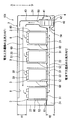
第1実施形態の電池パック1について図1及び図2を参照しながら説明する。図1は、電池パック1の構成及びパックケース2内における流体流れを示している。図2は、電池パック1の車両における搭載場所を示している。
(First embodiment)
The battery pack 1 of 1st Embodiment is demonstrated referring FIG.1 and FIG.2. FIG. 1 shows the configuration of the battery pack 1 and the fluid flow in the
電池パック1は、例えば内燃機関と電池に充電された電力によって駆動されるモータとを組み合わせて走行駆動源とするハイブリッド自動車、モータを走行駆動源とする電気自動車等に用いられる。電池パック1に含まれる複数の電池セル3は、例えばニッケル水素二次電池、リチウムイオン二次電池、有機ラジカル電池である。
The battery pack 1 is used in, for example, a hybrid vehicle that uses a traveling drive source by combining an internal combustion engine and a motor driven by electric power charged in the battery, an electric vehicle that uses a motor as a travel drive source, and the like. The plurality of
電池パック1は、複数の電池セル3と、密閉空間を形成するパックケース2と、パックケース2内で流体を循環させる流体駆動手段と、を備える。パックケース2の内部には、複数の電池セル3と流体駆動手段の一例である送風機4とが収容されている。
The battery pack 1 includes a plurality of
パックケース2は、内部に、複数の電池セル3及び送風機4が収容される筐体である。パックケース2は、通電可能に電気的に直列接続され、かつ積層設置された複数の電池セル3を収容する。パックケース2の内部には、送風機4によって強制的に流れる流体の循環経路をなす循環通路5が形成されている。循環通路5は、パックケース2の内部に形成され、流体が循環する通路である。循環通路5は、送風機4により送風された流体が電池セル3と熱交換した後、送風機4に吸い込まれる一連の流体の流通経路をなす。図1に図示するように、循環通路5は、流入通路54、吹出し通路50、天壁側通路51、電池通路52及び集合通路53を結ぶ一連の流通経路を構成する。
The
複数の電池セル3は、充電及び放電または温度調節に用いられる電子部品によって制御される。当該電子部品は、例えば、DC/DCコンバータ、送風機4を駆動するモータ、インバータによって制御される電子部品、各種の電子式制御装置等である。当該電子部品は、パックケース2に収容する形態でもよいし、パックケース2に直付けられて外部に設置される形態でもよい。また、当該電子部品は、パックケース2の内部において循環通路5に設置される場合には、流体の循環によって電池セル3とともに冷却することができる。
The plurality of
電池パック1は、パックケース2の内部に、少なくとも電池セル3の電圧と温度とを監視する電池監視ユニットを含む制御装置を備える。また、制御装置は、パックケース2に直付けられて外部に設置される形態でもよい。制御装置は、電池パック1に含まれる各電池セル3と通信可能に構成され、各電池セル3からの電池情報を受信することができる。電池監視ユニットは、各電池パック1に含まれる電池セル3について、温度、電圧、電流等の電池状態を監視する監視手段としての機能、また電圧の変化や電圧のばらつき及び電荷の移動量を算出する演算手段としての機能を有する。
The battery pack 1 includes a control device including a battery monitoring unit that monitors at least the voltage and temperature of the
制御装置または電池監視ユニットは、車両ECUと同様に入力回路、マイクロコンピュータ、及び出力回路を備えている。マイクロコンピュータが有する記憶手段には、電池情報がデータとして随時蓄積されている。蓄積される電池情報のデータは、例えば、電池パック1における電池電圧、充電電流、放電電流及び電池温度等である。 The control device or the battery monitoring unit includes an input circuit, a microcomputer, and an output circuit, like the vehicle ECU. Battery information is stored as data in the storage means of the microcomputer. The stored battery information data includes, for example, the battery voltage, the charging current, the discharging current, and the battery temperature in the battery pack 1.
電池パック1において所定本数設けられる通信線は、電池パック1に含まれるすべての電池セル3に関する所定の電池情報を制御装置等へ送信することができる通信部材である。複数の通信線は、電池パック1に含まれる電池セル3に接続されて、電池信号によって電池情報を制御装置等に出力する。例えば、通信線は、電圧検出線、温度検出線を含んで構成され、電池パック1における所定部位の電池温度、電池電圧を制御装置等に出力する。
The predetermined number of communication lines provided in the battery pack 1 are communication members that can transmit predetermined battery information regarding all the
電池監視ユニットは、電池パック1における所定部位間の電池電圧を電圧検出線を介して入力される信号に基づいて検出する。電池監視ユニットは、電池パック1における所定部位の電池温度を温度検出線を介して入力される信号に基づいて検出する。電池監視ユニットは、入力、記憶されたデータを用いて、電池パック1の放電電流の変化に伴うSOC(State of Charge)等の情報を計算、記録し、電池温度、単電池電圧、全電池電圧、及び電池電圧のばらつき等の各種情報を車両ECUに送信する。 The battery monitoring unit detects a battery voltage between predetermined parts in the battery pack 1 based on a signal input via a voltage detection line. The battery monitoring unit detects the battery temperature at a predetermined part in the battery pack 1 based on a signal input via the temperature detection line. The battery monitoring unit uses the input and stored data to calculate and record information such as SOC (State of Charge) associated with changes in the discharge current of the battery pack 1, and the battery temperature, single cell voltage, total battery voltage And various information such as battery voltage variations are transmitted to the vehicle ECU.
パックケース2は、内部の空間を包囲する複数の壁面からなる箱形を呈し、アルミニウム板または鉄板の成型品で形成されている。パックケース2は、例えば少なくとも6面を有するパックケースである。パックケース2は、複数のケース体を接合して組み立てることにより、内部に箱体状の空間を形成して作製することができる。また、パックケース2の複数の壁面のうち、所定の壁面には、放熱面積を大きくするために凸部または凹部を形成するようにしてもよい。
The
電池パック1に含まれる電池セル3は、パックケース2の内部空間において複数のセル積層体を構成する。複数のセル積層体は、図1に図示するように、パックケース2の内部空間において所定の間隔をあけて設置され、それぞれ電池ケース60に周囲を囲まれるように収容されている。各電池ケース60は、パックケース2の天壁20側がパックケース2の内部空間に向けて開口し、パックケース2の底壁22側が集合ダクト61に接続されている。これにより、循環通路5の一部であり、各セル積層体が設置される電池ケース60内に設けられる電池通路52等の各通路は、天壁20側でそれぞれ独立した流体の入口部を備え、底壁22側で一つの集合通路53に集まる流体の出口部を備える。
The
循環通路5は、パックケース2を形成する天壁20と複数の電池セル3との間に設けられる通路である電池上方通路と、パックケース2を形成する底壁22と複数の電池セル3との間に設けられる通路である電池下方通路と、を含む。電池上方通路は、天壁側通路51が相当する。電池下方通路は、底壁22に沿って電池セル3の下方に延びる集合通路53が相当する。天壁側通路51には、循環流体が天壁20に沿って主流方向F1に流れる。集合通路53には、循環流体が底壁22に沿ってF1とは逆向きの主流方向F2に流れる。
The
電池上方通路と電池下方通路は、流体駆動手段から吐出された流体が電池上方通路及び電池下方通路を経由してから流体駆動手段に吸入されるように、パックケース2の内部で区画形成された通路を構成する。図1に示すように、送風機4の吐出部(例えば吹出し通路50)は、天壁側通路51、電池通路52及び集合通路53を経由して、送風機4の吸入部(例えば流入通路54)に連通する。循環通路5は、送風機4の吐出部が天壁側通路51、電池通路52及び集合通路53を経由しないと、送風機4の吸入部に連通できないように、設けられる。具体的には、ケーシング42、電池ケース60及び集合ダクト61の連結構造により、送風機4から吐出された流体は、ショートカットして送風機4の吸入部に吸い込まれないようになっている。
The battery upper passage and the battery lower passage are defined inside the
電池上方通路(例えば天壁側通路51)は、上下方向に平行な通路断面の縦断面積が電池下方通路(例えば集合通路53)よりも大きく設定されている。例えば、比較の対象となる縦断面積は、各通路における最小の縦断面積同士である。つまり、電池上方通路における最小の縦断面積は、電池下方通路における最小の縦断面積よりも大きくなるように設定される。例えば、電池上方通路や電池下方通路に、電子部品、ジャンクションボックス、制御ボックス等の何らかの部材が存在する場合には、各通路の縦断面積は一定でない。この場合には、各通路の最小の縦断面積同士を比較し、電池上方通路の方が大きくなるように設定される。 The battery upper passage (for example, the top wall side passage 51) is set such that the vertical cross-sectional area of the passage cross section parallel to the vertical direction is larger than the battery lower passage (for example, the collecting passage 53). For example, the vertical cross-sectional areas to be compared are the minimum vertical cross-sectional areas in each passage. That is, the minimum vertical cross-sectional area in the battery upper passage is set to be larger than the minimum vertical cross-sectional area in the battery lower passage. For example, when any member such as an electronic component, a junction box, or a control box is present in the battery upper passage and the battery lower passage, the longitudinal sectional area of each passage is not constant. In this case, the minimum vertical cross-sectional areas of the passages are compared with each other, and the battery upper passage is set to be larger.
送風機4の作動時に発生する全騒音SPL(dB)については、以下の数式に示す関係がある。
(数式) SPL=Ks+10log10(ΔP2・Va)
The total noise SPL (dB) generated during the operation of the
(Expression) SPL = Ks + 10 log 10 (ΔP 2 · Va)
ただし、Ksはファン単体が独自に持つ比騒音である。10log10(ΔP2・Va)で求められる値は、有効騒音であり、送風量、送風圧力によって発生する音である。ΔPは、ファン全圧(mmAg)である。Vaは風量(m3/h)である。 However, Ks is a specific noise that the fan alone has. The value obtained by 10 log 10 (ΔP 2 · Va) is effective noise, and is a sound generated by the blowing amount and blowing pressure. ΔP is the fan total pressure (mmAg). Va is the air volume (m 3 / h).
上記の数式の関係から、電池上方通路の縦断面積を大きくすると、風量Vaが一定の場合、ΔPが小さくなるため、有効騒音を小さくすることができる。したがって、外部に伝搬する元の全騒音SPLを小さくすることができる。また、電池下方通路では、電池上方通路よりも縦断面積を小さいため、風量Vaが一定の場合、流速が大きくなる。天壁20を通じた放熱量は、流速に比例するため、電池下方通路の放熱量は電池上方通路より大きくなる。したがって、電池上方通路での流速低下による放熱量低下分は、電池下方通路において補充することができる。
From the relationship of the above mathematical formula, when the vertical cross-sectional area of the battery upper passage is increased, ΔP is decreased when the air volume Va is constant, so that the effective noise can be reduced. Therefore, the original total noise SPL propagating to the outside can be reduced. Further, since the vertical cross-sectional area of the battery lower passage is smaller than that of the battery upper passage, the flow velocity is increased when the air volume Va is constant. Since the heat radiation amount through the
以上の構成によれば、循環通路5を循環する流体は、電池上方通路を流通するときの方が電池下方通路を流通するときよりも流速が小さくなる。両方の通路には、同流量の流体が流通するからである。
According to the above configuration, the flow rate of the fluid circulating in the
電池上方通路は、上下方向に平行な通路断面の上下方向長さH1が電池下方通路の上下方向長さH2よりも大きく設定されることが好ましい。この構成によっても、電池上方通路の縦断面積を電池下方通路の縦断面積をよりも大きく設定することができる。また、電池上方通路の縦断面積が電池下方通路の縦断面積よりも大きく設定されている関係であれば、電池上方通路の上下方向長さH1が電池下方通路の上下方向長さH2以下であってもよい。例えば、図1の紙面奥行き方向の長さが、電池上方通路の方が電池下方通路よりもとても長ければ、上下方向長さH1が上下方向長さH2以下とすることができる。 In the battery upper passage, it is preferable that the vertical length H1 of the passage section parallel to the vertical direction is set larger than the vertical length H2 of the battery lower passage. Also with this configuration, the vertical cross-sectional area of the battery upper passage can be set larger than the vertical cross-sectional area of the battery lower passage. If the vertical cross-sectional area of the battery upper passage is set to be larger than the vertical cross-sectional area of the battery lower passage, the vertical length H1 of the battery upper passage is equal to or less than the vertical length H2 of the battery lower passage. Also good. For example, if the length in the depth direction in FIG. 1 is much longer in the battery upper passage than in the battery lower passage, the vertical length H1 can be made equal to or smaller than the vertical length H2.
集合ダクト61は、各電池セル3の下流側端部31と、ケーシング42の吸入部(流入通路54)と、底壁22と、底壁22に隣接する複数の側壁23,24等とを繋ぐダクトである。集合ダクト61は、各電池通路52を流出した空気が底壁22及び複数の側壁23,24等に接触しうる集合通路53を形成する。したがって、電池パック1が有する集合通路53は、少なくとも、各電池セル3の下流側端部31と、底壁22と、複数の側壁23,24等と、で形成される通路である。
The
集合通路53は、所定の間隔をあけて並ぶすべてのセル積層体の下方からケーシング42の吸込み口までにわたって底壁22に沿って延び、流入通路54に繋がっている。循環通路5に含まれる集合通路53は、複数の電池セル3と熱交換した後の流体が集合して流体駆動手段に向かって同一方向に流れる通路である。したがって、集合通路53を流れる流体から放出される熱は、底壁22等のケース壁に伝達され、底壁22等を通してパックケース2の外部に排出される。
The collecting
さらに、送風機4によって天壁側通路51に達した流体は、電池ケース60上部の入口部から各電池通路52に流入する。電池通路52は、隣り合う電池セル3の間に形成したセル間通路とすることもできる。天壁側通路51は、天壁20と複数の電池セル3との間に形成される通路であり、流体駆動手段から吐出された流体が複数の電池セル3に向かって流れる電池上流側通路でもある。
Further, the fluid that has reached the top
そして、循環通路5を流れる流体は、電池通路52を流れるときに、各電池セル3の外表面から吸熱して各電池セル3を冷却する。各電池セル3を冷却した流体は、それぞれ、電池ケース60下部の出口部から集合通路53に集められ、流入通路54を通して送風機4に吸入される。この場合、電池セル3の放熱手段の一つは、セルの外装パックケース面である。
The fluid flowing through the
また、流体は、パックケース2内を循環する際に、正極端子、負極端子からなる電池セル3の電極端子30や、異極端子間を電気的に接続するバスバーにも接触するため、電極端子30やバスバーも放熱手段の一つを構成しうる。電極端子30やバスバーは、電池ケース60内において、上部側、流体流れの上流側に位置している。したがって、送風機4から流出した流体は、電極端子30やバスバーの周囲を通過した後、集合通路53に流入する。
Further, when the fluid circulates in the
送風機4は、パックケース2に収容された複数個の電池セル3を冷却する流体を、パックケース2に構成された循環通路5に循環させる流体駆動手段の一例である。電池冷却のための流体としては、例えば、空気、各種のガス、水、冷媒を用いることができる。ここでは、送風機4は、循環通路5に空気を強制的に循環させる流体駆動手段とする。送風機4は、モータ41と、モータ41により回転されるシロッコファン40と、シロッコファン40を内蔵するケーシング42とを備える。また、ケーシング42は、循環通路5の一部である流入通路54を形成する。
The
送風機4は、例えば、電池監視ユニットを含む制御装置によって制御される。電池セル3は、電流が取り出される出力時及び充電される入力時に自己発熱する。制御装置は、各電池パック1内の電池セル3の温度を常時モニターし、電池セル3の温度に基づいて送風機4の運転を制御する。
The
流入通路54は、ケーシング42の吸込み口を含み、シロッコファン40の回転軸方向に延びる流体駆動手段の吸入部であり、シロッコファン40によって吸い込まれる空気が通る。シロッコファン40は、図示するように、パックケース2の内部空間の下部であってパックケース2の側壁21に近接するように設置されている。モータ41は、側壁21とシロッコファン40との間に設置されている。シロッコファン40の回転軸は、パックケース2の天壁20及び底壁22に平行となる姿勢で設置される。流入通路54は、電池セル3側に位置する通路であり、集合通路53に接続される。すなわち、ケーシング42の吸込み口は、集合ダクト61に接続されている。
The
さらにケーシング42は、循環通路5の一部である吹出し通路50を形成する。吹出し通路50は、シロッコファン40の回転軸に直交するファンの遠心方向に延びる通路であり、流体駆動手段の吐出部でもある。吹出し通路50は、流入通路54に直交する方向に延びる通路である。したがって、吹出し通路50は、パックケース2の内部空間において上方に延びる。ケーシング42の吐出部は、上方に延びる送風ダクト43に接続される。送風ダクト43は、パックケース2の天壁20近くの部位で開口する。この構成により、吹出し通路50は、パックケース2の内部空間において天壁20近くの部位まで連通する。
Further, the
循環通路5は、送風ダクト43、電池ケース60、及びケーシング42によって形成された通路ではパックケース2の壁面に露出せず、天壁側通路51、集合通路53においてパックケース2の壁面に対して露出する通路を構成する。したがって、循環流体は、天壁側通路51や集合通路53を流れるときに、パックケース2の壁面に接触する。循環通路5は、送風機4の運転によってパックケース2内を循環する循環流体が、パックケース2を形成する複数の壁面のうち、少なくとも一つの壁面に接触しながら流れる通路部分を含む。
The
この流体循環の過程で空気が接触する壁面が天壁20、底壁22であり、天壁20や底壁22に接触しながら空気が流れる通路部分が天壁側通路51や集合通路53である。循環空気は集合通路53を流れる際に、天壁側通路51の流通時よりも流速が増加し、電池セル3と熱交換した直後に、電池セル3から吸熱した熱を底壁22を通してパックケース2の外部に放熱する。
Wall surfaces in contact with air in the course of fluid circulation are the
また、循環空気は天壁側通路51を流れる際に、集合通路53の流通時よりも流速が低下し、電池セル3との熱交換の直前に、天壁20を通してパックケース2の外部に放熱する。天壁20を通して放出された熱は、自然対流によってパックケース2の外部に放熱される。したがって、天壁20の全体や底壁22の全体が、パックケース2内の電池セル3の熱を外部に放出する際の放熱面として機能することになる。
Further, when the circulating air flows through the top
また、底壁22や天壁20は、パックケース2を形成する複数の壁面のうち、最も大きい表面積を有する壁面であることが好ましい。放熱面である底壁22、天壁20がパックケース2の壁面において表面積の最も大きい壁面であることにより、外部への放熱効果を大きくでき、電池の効果的な冷却を実施できるからである。例えば、パックケース2が直方体である場合などでは、底壁22及び天壁20は、最も大きい表面積を有する壁面となる。
The
図2に示すように、電池パック1は、車両7の車室内70に設けられる前部座席73の下方や後部座席74の下方に設置することができる。電池パック1は、底壁22や集合通路53を下側にした姿勢で、前部座席73や後部座席74の下方に設置される。また、電池パック1は、電池冷却のためのダクトの設ける必要がないという特徴を有するため、パックケース2を座席の下方に設置するのに適している。
As shown in FIG. 2, the battery pack 1 can be installed below a
電池パック1のパックケース2は、車両7に設けられた床面に接触するように車両7に搭載することができる。パックケース2内の熱は、ケース壁を介して床面に伝達される。パックケース2の一部である底壁22は、床面に接触するようにしてもよい。パックケース2の内部には、循環流がパックケース2内の電池セル3に接触して電池セル3と熱交換した後、底壁22に接触しながら流下する集合通路53が設けられる。したがって、パックケース2内の熱は、電池セル3と熱交換した後の集合通路53を流れる流体から、底壁22を介して床面に伝達されうる。
The
また、後部座席74の下方の電池パック1を設置する空間は、トランクルーム71よりも下方のトランクルーム裏空間72に連通させるようにしてもよい。また当該設置空間は、車外に連通するようにも構成できる。また、底壁22と床面との接触部には、熱伝導性に優れた放熱シートを介在させるようにしてもよい。パックケース2内の熱は、底壁22から放熱シートを介して床面に伝達される。
Further, the space where the battery pack 1 below the
また、電池パック1は、トランクルーム71に設置してもよい。また、電池パック1は、スペアタイヤ、工具等を収納可能で、トランクルームより下方に設けられたトランクルーム下エリアに設置するようにしてもよい。
Further, the battery pack 1 may be installed in the
次に、電池パック1がもたらす作用効果について説明する。電池パック1は、通電可能に接続される複数の電池セル3と、複数の電池セル3を収容するパックケース2と、パックケース2の内部に循環させる流体駆動手段と、パックケース2の内部に形成される流体の循環通路5と、を備える。
Next, the operational effects brought about by the battery pack 1 will be described. The battery pack 1 includes a plurality of
循環通路5は、パックケース2の天壁20と複数の電池セル3との間に設けられる通路である電池上方通路(天壁側通路51)と、パックケース2の底壁22と複数の電池セル3との間に設けられる通路である電池下方通路(集合通路53)と、を含む。電池上方通路と電池下方通路は、流体駆動手段から吐出された流体が電池上方通路及び電池下方通路を経由してから流体駆動手段に吸入されるように、筐体の内部で区画形成された通路を構成する。電池上方通路は、上下方向に平行な通路断面の縦断面積が電池下方通路よりも大きく設定される。
The
この電池パック1では、流体駆動手段からの吐出流体は電池上方通路及び電池下方通路を経由してから流体駆動手段に吸入される。このため、流体は、電池上方通路と電池下方通路との間で電池セル3と熱交換しながら、循環通路5を循環し続ける。すなわち、流体駆動手段からの吐出流体の主流は、電池上方通路、電池下方通路及び電池セル3をショートカットして流体駆動手段に戻ってくるのではなく、電池上方通路、電池下方通路及び電池セル3を経由して戻ってくる。
In the battery pack 1, the fluid discharged from the fluid driving means is sucked into the fluid driving means after passing through the battery upper passage and the battery lower passage. For this reason, the fluid continues to circulate in the
さらに、電池上方通路が電池下方通路よりも広い通路に設定されているため、循環流体の流速は、電池上方通路では電池下方通路よりも遅くなる。循環流体は、電池上方通路を通るときは電池下方通路を通るときよりも流速が遅いため、パックケース2の壁を介して外部に伝搬する騒音が抑えられる。一方、電池下方通路を通るときの流体は、電池上方通路を通るときよりも流速が早いため、パックケース2の壁に伝わる放熱量が大きくなり、外部への放熱性能が向上する。このように電池パック1によれば、循環通路5の場所によって、放熱性能向上と騒音抑制向上の効果を使い分ける。したがって、電池冷却性能の確保と騒音抑制との両立が図れる電池パック1を提供できる。
Furthermore, since the battery upper passage is set wider than the battery lower passage, the flow rate of the circulating fluid is slower in the battery upper passage than in the battery lower passage. Since the circulating fluid has a slower flow velocity when passing through the battery upper passage than when passing through the battery lower passage, noise propagating to the outside through the wall of the
また、電池上方通路は、上下方向に平行な通路断面の上下方向長さH1が電池下方通路における上下方向長さH2よりも大きく設定される。これによれば、循環流体は、電池上方通路を流通するときに、電池下方通路を流通するときに比べて、パックケース2の壁に衝突しにくい。これにより、流体が電池上方通路を流通するときに天壁20への衝突が軽減されるので、外部への騒音伝搬は、天壁20側で底壁22側よりも容易に抑制される。
In the battery upper passage, the vertical length H1 of the passage cross section parallel to the vertical direction is set larger than the vertical length H2 in the battery lower passage. According to this, the circulating fluid is less likely to collide with the wall of the
また、パックケース2は、着座する乗員の頭部よりも低い位置で車両7に搭載されることが好ましい。この電池パック1によれば、電池上方通路は、電池下方通路よりも乗員の耳に近い位置に設けられる。このため、電池上方通路を流体が流通することによって発生する騒音の方が、電池下方通路を流体が流通することによって発生する騒音よりも乗員に伝わりやすい。そこで、電池パック1では、電池上方通路を通るときの流体の流速の方が小さいため、乗員に近いパックケース2の上部側の壁を介して外部への音の伝搬を抑え、乗員への騒音伝搬を効果的に抑制することができる。
The
パックケース2は、底壁22が車両7に設けられた床面に接触して車両7に搭載される。これによれば、パックケース2が車両7の床面に直付けされた状態であるので、電池下方通路を流れる早い流速の流体の熱が底壁22から床面を介して外部に放熱される。このように、電池セル3を冷却した直後の流速の大きい流体を底壁22に接触させて底壁22に熱移動させ、さらに床面を介して外部に放熱するという熱損失を抑えた伝熱経路を構築できる。また、電池パック1は、パックケース2内の循環流体によって電池セル3を冷却するため、電池冷却のためのダクトを設ける必要がない。したがって、電池パック1は、パックケース2を床面に直付けするのに適したパックである。
The
また、電池パック1に内蔵される流体駆動手段は、電池パック1の内部に流体を循環させる。この構成によれば、電池冷却用の流体をパック内部で循環するので、流体の排出に伴う外部への音の伝搬がない。したがって、流体駆動手段等のパック内部から発生する騒音がパック外部へ伝搬することを抑制することができる。また、電池パック1の内部を循環し続ける循環流体によって、電池冷却を実施するため、電池パック1に接続する冷却用ダクトが不要である。すなわち、ダクトに関する部品費用、部品管理等が不要で、ダクトの接続する工程も要しない。したがって、電池パック1の部品点数を削減できるので、製造にかかるコストを抑制でき、また電池パック1を搭載する際の自由度を向上することができる。 Further, the fluid driving means built in the battery pack 1 circulates the fluid inside the battery pack 1. According to this configuration, since the battery cooling fluid is circulated inside the pack, there is no propagation of sound to the outside due to the discharge of the fluid. Therefore, it is possible to suppress the noise generated from the inside of the pack such as the fluid driving means from propagating to the outside of the pack. Further, since the battery cooling is performed by the circulating fluid that continues to circulate inside the battery pack 1, a cooling duct connected to the battery pack 1 is unnecessary. That is, there is no need for parts costs related to the duct, parts management, etc., and no duct connecting process is required. Therefore, since the number of parts of the battery pack 1 can be reduced, the manufacturing cost can be suppressed, and the degree of freedom in mounting the battery pack 1 can be improved.
また、パックケース2内に循環流体を形成することにより、パックケース2を形成する複数の壁を放熱媒質として活用できるので、パックケース2の外部への放熱を促すことができる。これにより、電池セル3の発熱を効果的にパックケース2の外部に排熱する効率的な放熱経路を構築できる。また、パック内部には埃が侵入しにくく、結露も生じにくい。さらに、パック内部に形成される循環流によって、パック内部の流体を十分にかき混ぜることができるため、複数の電池セル3に対する吸熱効果を高めることにも貢献できる。
In addition, by forming a circulating fluid in the
また、パックケース2は、循環通路5を含む密閉空間を形成する。この構成によれば、従来の冷却用の空気を大量に外部から取り入れ、電池を冷却した後、外部に排気する方式に比べ、パックケース2に流体の流入口及び流出口がなく、また流体の排出に伴って外部へ音が伝搬することがない。したがって、送風機4等から発生する騒音がパックケース2の外部へ伝搬することを抑制することができる。また、パックケース2内に埃等が侵入しにくく、結露も生じにくい。さらに冷却用の流体が密閉空間に設けられた循環通路5を循環するため、電池セル3の熱を十分に吸熱するために必要な空気の循環流量を確保することも可能である。また、密閉空間に形成される循環流によって、パックケース2の内部を十分にかき混ぜることができるため、電池セル3に対する吸熱効果を高めることが可能である。
The
また、パックケース2の内部に設けられた循環通路5は、パックケース2を形成する複数の壁面に囲まれている。このように、循環通路5を取り囲むパックケース2の複数の壁面を放熱媒質として活用することができるので、外部への放熱面積を大きくでき、パックケース2の外部へ放熱を促進することができる。これにより、電池セル3の発熱を効果的にパックケース2の外部に排熱する熱経路を構築するこができる。すなわち、パックケース2の壁面を広く放熱面積として活用する効果的な電池冷却を実現できるのである。
Further, the
集合通路53は、少なくとも、電池セル3の下流側端部31と、底壁22と、底壁22に隣接する複数の側壁23,24等と、で形成される通路である。この構成によれば、循環流体が集合通路53を流れる際に、底壁22、複数の側壁23,24等を通じてパックケース2の外部に放熱させることができる。このようにパックケース2の少なくとも一つの壁面を放熱媒質として活用することができるので、外部への放熱面積を確保でき、電池セル3の発熱を効果的にパックケース2の外部に排熱する熱経路を構築できる。また、この構成によれば、電池セル3から吸熱した後の流体を確実に集合させる流れを形成でき、さらに流体駆動手段に向かって同一方向に流下させる円滑な流れを形成できる。
The collecting
また、底壁22は、パックケース2を形成する複数の壁面のうち、最も大きい表面積を有する壁面を構成することが好ましい。この構成によれば、電池冷却後の流体について、放熱面を構成する壁面がパックケース2の壁面において表面積の最も大きい壁面であることにより、外部への放熱効果を大きくでき、電池冷却の効果を大きくできる。
Moreover, it is preferable that the
また、複数の電池セル3は、少なくとも、パックケース2の天壁20に沿う方向に並んで設けられている。流体駆動手段から流出した流体は、天壁20に沿って流れ、さらに下方に向けて流下して各電池セル3と熱交換する。流体駆動手段から流出した流体を天壁20に接触させ、さらに天壁20に沿って並ぶ複数の電池セル3に向けて流下させるため、各電池セル3へ流れる流量のばらつきを抑制し、均一化が図れる。また、この構成によれば、流体駆動手段から流出した流体の熱を、流体と電池セル3とが熱交換する前に、天壁20を通じてパックケース2の外部に放出することができる。このように、流体駆動手段に吸い込まれる前に外部に放出できなかった電池セル3の熱を電池セル3と熱交換する前にパックケース2の外部に排熱する熱経路を構築するこができる。
Further, the plurality of
(第2実施形態)
第2実施形態では、放熱促進のための放熱促進手段を電池上方通路(天壁側通路51)に備えた電池パック101について図3を参照して説明する。図3において、第1実施形態と同様の構成であるものは同一の符号を付し、同様の作用、効果を奏するものである。第2実施形態で特に説明しない構成、作用、効果については、第1実施形態と同様である。以下、第1実施形態と異なる点についてのみ説明する。また、第2実施形態において第1実施形態と同様の構成を有するものは、第1実施形態で説明した同様の作用、効果を奏するものとする。
(Second Embodiment)
In the second embodiment, a
図3に示すように、天壁20の内面には、天壁側通路51(電池上方通路)を流通する流体と接触するための接触表面積を拡大し、流体から吸収した熱を天壁20に伝達する吸熱促進手段が設けられる。吸熱促進手段は、天壁20に一体に設けられ、天壁20との間で熱移動を可能にする部分である。吸熱促進手段は、天壁20に一体に設けられることで、天壁20を介して伝熱するための表面積を拡大する役割を有する。すなわち、吸熱促進手段は、電池上方通路を流れる流体との天壁20との接触面積を拡大して、パックケース2の外部への放熱量を大きくする放熱促進手段でもある。
As shown in FIG. 3, on the inner surface of the
吸熱促進手段は、例えば、複数のフィン8によって構成することができる。複数のフィン8は、天壁20の内面から突出する凸部である。各フィン8は、天壁側通路51における流体の主流方向F1に延びる凸条部である。したがって、流体は、電池上方通路を流れる際に、各フィン8の外側面に接触しながら、天壁20に沿うように流れる。各フィン8は、流体の流通抵抗を抑える形状の吸熱促進部材である。
The heat absorption promotion means can be constituted by a plurality of fins 8, for example. The plurality of fins 8 are convex portions protruding from the inner surface of the
電池パック101で流体が循環通路5を循環すると、電池通路52に流入して各電池セル3から吸熱して各電池セル3を冷却した流体は、さらに集合通路53を流れる過程で流速が増大し、底壁22や側壁23,24等を通して外部に放熱する。さらに流体は、送風機4の吸入部(流入通路54)に吸入され、吐出部(吹出し通路50)から天壁側通路51を流通し、複数のフィン8に接触することで冷却される。循環流体に含まれる電池セル3の発熱は、複数のフィン8を介して天壁20に伝わり、天壁20の外表面から外部に排出される。循環流体は、天壁20を通して外部に放熱した後、再び電池通路52に流入して各電池セル3を冷却する。
When the fluid circulates in the
第2実施形態の電池パック101によれば、電池下方通路よりも広い電池上方通路に吸熱促進手段を設けることで、低流速によって低下した放熱量を補うことができる。すなわち、電池上方通路の低流速のための構成と吸熱促進手段とによって、第1実施形態で説明した騒音抑制の効果を得るとともに、低速による放熱量の低下を改善することができる。
According to the
(他の実施形態)
上述の実施形態では、本発明の好ましい実施形態について説明したが、本発明は上述した実施形態に何ら制限されることなく、本発明の主旨を逸脱しない範囲において種々変形して実施することが可能である。上記実施形態の構造は、あくまで例示であって、本発明の範囲はこれらの記載の範囲に限定されるものではない。本発明の範囲は、特許請求の範囲の記載によって示され、さらに特許請求の範囲の記載と均等の意味及び範囲内での全ての変更を含むものである。
(Other embodiments)
In the above-described embodiment, the preferred embodiment of the present invention has been described. However, the present invention is not limited to the above-described embodiment, and various modifications can be made without departing from the spirit of the present invention. It is. The structure of the said embodiment is an illustration to the last, Comprising: The scope of the present invention is not limited to the range of these description. The scope of the present invention is indicated by the description of the scope of claims, and further includes meanings equivalent to the description of the scope of claims and all modifications within the scope.
上記実施形態の電池パックでは、電池上方通路は流体駆動手段からの吐出流体が複数の電池セル3に向かって流れる電池上流側通路に相当し、電池下方通路は複数の電池セル3と熱交換後の流体が流体駆動手段に向かって流れる電池下流側通路に相当する。本発明に含まれる電池上方通路及び電池上方通路は、この形態に限定されない。例えば、電池下方通路が流体駆動手段からの吐出流体が複数の電池セル3に向かって流れる電池上流側通路に相当し、電池上方通路が複数の電池セル3と熱交換後の流体が流体駆動手段に向かって流れる電池下流側通路に相当する実施形態であってもよい。
In the battery pack of the above embodiment, the battery upper passage corresponds to the battery upstream passage through which the fluid discharged from the fluid driving means flows toward the plurality of
第2実施形態の吸熱促進手段は、天壁20の内面から突出する複数のフィン8で構成する他、天壁20の内面から突出する様々な形状の凸部、天壁20の内面に形成される凹部などで構成してもよい。
The heat absorption promotion means of the second embodiment is formed of a plurality of fins 8 protruding from the inner surface of the
上記実施形態の電池パック1,101は、パックケース2の内部を密閉空間とするものであるが、完全に密閉する構造でないパックケースを有するものとしてもよい。例えば、電池パック1は、所定値以上の圧力が作用したときに開放する通路を有する圧力弁を備えてもよい。この場合には、パックケース内が所定の圧力以上になったときにパックケースの外部への空気の排出が行われる。これにより、不必要な空気の排出を防止でき、騒音抑制効果を奏する。
The battery packs 1 and 101 of the above embodiment have the inside of the
この圧力弁は、パックケースの内部空間と外部とを連通する開放通路を形成する。開放通路は、なんらかの原因によりパックケースの内部圧力が高まった場合、圧力弁が作動することにより、循環通路5からあふれた空気が外部に排出されるときに通る通路となる。例えば、開放通路は、集合通路53の一部をなさない底壁22の部分を貫通するように設けられる。換言すれば、開放通路は、循環通路5から漏れたパックケース2内部の空気が流出する位置に設けることが好ましい。例えば、開放通路は、循環通路5や集合通路53から外れたケーシング42に直面する位置で、底壁22を貫通してパックケース2の内部と外部とを連通する。開放通路は、パックケースを貫通する小径の穴によって形成され、さらにこの穴の周囲には、他の部分よりも薄肉の円環部が形成されている。この小径の穴は、外部の空気がパックケースの内部に取り込まれず、パックケースの内部空気が循環通路5を循環し続ける状況では、開放通路を通して空気が外部に排出されない大きさに設定されている。したがって、パックケースの内部空間は、開放通路を除き、密閉された空間を形成する。
This pressure valve forms an open passage that communicates the internal space of the pack case with the outside. When the internal pressure of the pack case increases due to some cause, the open passage becomes a passage through which the air overflowing from the
パックケース2の内部に設けられる送風機4には、シロッコファンの他、軸流ファン、ターボファン等を用いることができる。
As the
また、パックケース2において、最も表面積の大きい壁面は、各パックケースの天面や底面に限定されず、側面やその他の面であってもよい。
Further, in the
1,101…電池パック
2…パックケース(筐体)
3…電池セル(電池)
4…送風機(流体駆動手段)
5…循環通路
20…天壁
22…底壁
51…天壁側通路(電池上方通路)
53…集合通路(電池下方通路)
1,101 ...
3. Battery cell (battery)
4 ... Blower (fluid drive means)
5 ...
53 ... Collecting passage (battery lower passage)
Claims (5)
前記複数の電池を収容する筐体(2)と、
前記複数の電池を冷却する流体を前記筐体の内部に循環させる流体駆動手段(4)と、
前記筐体の内部に形成される前記流体の循環通路であって、前記流体駆動手段から吐出された流体が前記複数の電池と熱交換した後、前記流体駆動手段に吸入される一連の流通経路をなす循環通路(5)と、
を備え、
前記循環通路は、前記筐体を形成する壁の一つである天壁(20)と前記複数の電池との間に設けられる通路である電池上方通路(51)と、前記筐体を形成する壁の一つである底壁(22)と前記複数の電池との間に設けられる通路である電池下方通路(53)と、を含み、
前記電池上方通路と前記電池下方通路は、前記流体駆動手段から吐出された前記流体が前記電池上方通路及び前記電池下方通路を経由してから前記流体駆動手段に吸入されるように、前記筐体の内部で区画形成された通路を構成し、
前記電池上方通路は、前記電池上方通路を流れる前記流体の流れ方向の全体にわたって上下方向に平行な通路断面の縦断面積が前記電池下方通路よりも大きく設定されており、
少なくとも前記電池下方通路を流れるときの前記流体は、前記筐体の壁を介して外部に放熱することを特徴とする電池パック。 A plurality of batteries (3) connected to be energized;
A housing (2) for housing the plurality of batteries;
Fluid driving means (4) for circulating a fluid for cooling the plurality of batteries in the housing;
A circulation path of the fluid formed inside the casing, and a series of flow paths through which the fluid discharged from the fluid driving means is sucked into the fluid driving means after exchanging heat with the plurality of batteries. A circulation passage (5),
With
The circulation passage forms the housing with a battery upper passage (51) which is a passage provided between the top wall (20) which is one of the walls forming the housing and the plurality of batteries. A bottom wall (22) that is one of the walls and a battery lower passage (53) that is a passage provided between the plurality of batteries,
The battery upper passage and the battery lower passage are arranged so that the fluid discharged from the fluid driving means is sucked into the fluid driving means after passing through the battery upper passage and the battery lower passage. A passage formed in the interior of
The battery upper passage is set such that a vertical cross-sectional area of a passage cross section parallel to the vertical direction over the entire flow direction of the fluid flowing through the battery upper passage is larger than that of the battery lower passage .
At least the fluid when flowing in the battery lower passage, the battery pack characterized that you dissipated to the outside through the wall of the housing.
Priority Applications (1)
| Application Number | Priority Date | Filing Date | Title |
|---|---|---|---|
| JP2013214998A JP6146252B2 (en) | 2013-10-15 | 2013-10-15 | Battery pack |
Applications Claiming Priority (1)
| Application Number | Priority Date | Filing Date | Title |
|---|---|---|---|
| JP2013214998A JP6146252B2 (en) | 2013-10-15 | 2013-10-15 | Battery pack |
Publications (2)
| Publication Number | Publication Date |
|---|---|
| JP2015079598A JP2015079598A (en) | 2015-04-23 |
| JP6146252B2 true JP6146252B2 (en) | 2017-06-14 |
Family
ID=53010882
Family Applications (1)
| Application Number | Title | Priority Date | Filing Date |
|---|---|---|---|
| JP2013214998A Active JP6146252B2 (en) | 2013-10-15 | 2013-10-15 | Battery pack |
Country Status (1)
| Country | Link |
|---|---|
| JP (1) | JP6146252B2 (en) |
Families Citing this family (2)
| Publication number | Priority date | Publication date | Assignee | Title |
|---|---|---|---|---|
| KR101925978B1 (en) | 2014-08-22 | 2018-12-06 | 엘에스엠트론 주식회사 | Energy storage device module |
| CN114976372A (en) * | 2021-02-22 | 2022-08-30 | 华为数字能源技术有限公司 | Battery energy storage system and electric automobile |
Family Cites Families (5)
| Publication number | Priority date | Publication date | Assignee | Title |
|---|---|---|---|---|
| JP3777981B2 (en) * | 2000-04-13 | 2006-05-24 | トヨタ自動車株式会社 | Vehicle power supply |
| JP4366100B2 (en) * | 2003-03-24 | 2009-11-18 | パナソニックEvエナジー株式会社 | Battery pack |
| JP4788466B2 (en) * | 2006-04-28 | 2011-10-05 | トヨタ自動車株式会社 | Battery cooling structure |
| JP2009170370A (en) * | 2008-01-18 | 2009-07-30 | Toyota Motor Corp | Temperature adjusting mechanism |
| JP2011076967A (en) * | 2009-10-01 | 2011-04-14 | Honda Motor Co Ltd | Battery pack |
-
2013
- 2013-10-15 JP JP2013214998A patent/JP6146252B2/en active Active
Also Published As
| Publication number | Publication date |
|---|---|
| JP2015079598A (en) | 2015-04-23 |
Similar Documents
| Publication | Publication Date | Title |
|---|---|---|
| JP5842867B2 (en) | Battery cooling device | |
| JP6405912B2 (en) | Battery pack | |
| JP6384423B2 (en) | Battery pack | |
| JP6297922B2 (en) | Battery pack | |
| JP5330810B2 (en) | Battery box for storing battery module and railcar equipped with the same | |
| JP6149610B2 (en) | Battery cooling device | |
| JP5776735B2 (en) | Battery temperature control device | |
| JP6187326B2 (en) | Battery pack | |
| JP2015072741A (en) | Battery pack | |
| JP2005349955A (en) | Cooling structure for power storage mechanism | |
| CN107949951B (en) | Battery pack | |
| JP5892119B2 (en) | Battery cooling device | |
| CN107851868B (en) | Battery pack | |
| JP6089980B2 (en) | Battery cooling device | |
| JP6167933B2 (en) | Battery pack | |
| JP2017037755A (en) | Battery pack | |
| JP4742514B2 (en) | Battery pack and its casing | |
| JP6040843B2 (en) | Battery cooling device | |
| JP6507920B2 (en) | Battery pack | |
| JP6146252B2 (en) | Battery pack | |
| JP6136715B2 (en) | Battery cooling device | |
| JP5835394B2 (en) | Battery cooling device | |
| JP6119529B2 (en) | Battery system | |
| JP6390548B2 (en) | Battery pack | |
| JP6206255B2 (en) | Battery pack |
Legal Events
| Date | Code | Title | Description |
|---|---|---|---|
| A621 | Written request for application examination |
Free format text: JAPANESE INTERMEDIATE CODE: A621 Effective date: 20151221 |
|
| A977 | Report on retrieval |
Free format text: JAPANESE INTERMEDIATE CODE: A971007 Effective date: 20161006 |
|
| A131 | Notification of reasons for refusal |
Free format text: JAPANESE INTERMEDIATE CODE: A131 Effective date: 20161025 |
|
| A521 | Request for written amendment filed |
Free format text: JAPANESE INTERMEDIATE CODE: A523 Effective date: 20161222 |
|
| TRDD | Decision of grant or rejection written | ||
| A01 | Written decision to grant a patent or to grant a registration (utility model) |
Free format text: JAPANESE INTERMEDIATE CODE: A01 Effective date: 20170418 |
|
| A61 | First payment of annual fees (during grant procedure) |
Free format text: JAPANESE INTERMEDIATE CODE: A61 Effective date: 20170501 |
|
| R151 | Written notification of patent or utility model registration |
Ref document number: 6146252 Country of ref document: JP Free format text: JAPANESE INTERMEDIATE CODE: R151 |
|
| R250 | Receipt of annual fees |
Free format text: JAPANESE INTERMEDIATE CODE: R250 |
|
| R250 | Receipt of annual fees |
Free format text: JAPANESE INTERMEDIATE CODE: R250 |
|
| R250 | Receipt of annual fees |
Free format text: JAPANESE INTERMEDIATE CODE: R250 |
|
| R250 | Receipt of annual fees |
Free format text: JAPANESE INTERMEDIATE CODE: R250 |