JP6558990B2 - 電子装置およびその製造方法とリペア方法 - Google Patents
電子装置およびその製造方法とリペア方法 Download PDFInfo
- Publication number
- JP6558990B2 JP6558990B2 JP2015142652A JP2015142652A JP6558990B2 JP 6558990 B2 JP6558990 B2 JP 6558990B2 JP 2015142652 A JP2015142652 A JP 2015142652A JP 2015142652 A JP2015142652 A JP 2015142652A JP 6558990 B2 JP6558990 B2 JP 6558990B2
- Authority
- JP
- Japan
- Prior art keywords
- thin film
- wiring
- repair
- insulating film
- film
- Prior art date
- Legal status (The legal status is an assumption and is not a legal conclusion. Google has not performed a legal analysis and makes no representation as to the accuracy of the status listed.)
- Active
Links
- 238000000034 method Methods 0.000 title claims description 78
- 238000004519 manufacturing process Methods 0.000 title claims description 23
- 230000008439 repair process Effects 0.000 claims description 270
- 239000010408 film Substances 0.000 claims description 251
- 239000010409 thin film Substances 0.000 claims description 156
- 230000008569 process Effects 0.000 claims description 34
- 238000005530 etching Methods 0.000 claims description 22
- 238000000206 photolithography Methods 0.000 claims description 16
- 238000001182 laser chemical vapour deposition Methods 0.000 claims description 9
- 229920002120 photoresistant polymer Polymers 0.000 claims description 5
- 239000004020 conductor Substances 0.000 claims description 3
- 230000002950 deficient Effects 0.000 claims description 3
- 230000001678 irradiating effect Effects 0.000 claims description 3
- 238000002834 transmittance Methods 0.000 claims description 2
- 239000011229 interlayer Substances 0.000 description 75
- 239000004973 liquid crystal related substance Substances 0.000 description 50
- 239000010410 layer Substances 0.000 description 25
- 239000000758 substrate Substances 0.000 description 23
- 229910052751 metal Inorganic materials 0.000 description 16
- 239000002184 metal Substances 0.000 description 16
- 230000015572 biosynthetic process Effects 0.000 description 13
- 238000000151 deposition Methods 0.000 description 12
- 238000012986 modification Methods 0.000 description 12
- 230000004048 modification Effects 0.000 description 12
- 239000004065 semiconductor Substances 0.000 description 12
- 230000008021 deposition Effects 0.000 description 11
- WFKWXMTUELFFGS-UHFFFAOYSA-N tungsten Chemical compound [W] WFKWXMTUELFFGS-UHFFFAOYSA-N 0.000 description 11
- 229910052721 tungsten Inorganic materials 0.000 description 11
- 239000010937 tungsten Substances 0.000 description 11
- 230000007547 defect Effects 0.000 description 10
- 230000005540 biological transmission Effects 0.000 description 8
- 230000000694 effects Effects 0.000 description 6
- 230000005684 electric field Effects 0.000 description 6
- 229910021417 amorphous silicon Inorganic materials 0.000 description 5
- 238000005229 chemical vapour deposition Methods 0.000 description 5
- 230000002349 favourable effect Effects 0.000 description 5
- 238000001459 lithography Methods 0.000 description 5
- XKRFYHLGVUSROY-UHFFFAOYSA-N Argon Chemical compound [Ar] XKRFYHLGVUSROY-UHFFFAOYSA-N 0.000 description 4
- 150000001728 carbonyl compounds Chemical class 0.000 description 4
- 239000011651 chromium Substances 0.000 description 4
- 230000006866 deterioration Effects 0.000 description 4
- 239000007789 gas Substances 0.000 description 4
- 239000011159 matrix material Substances 0.000 description 4
- IJGRMHOSHXDMSA-UHFFFAOYSA-N Atomic nitrogen Chemical compound N#N IJGRMHOSHXDMSA-UHFFFAOYSA-N 0.000 description 3
- 229910052581 Si3N4 Inorganic materials 0.000 description 3
- 238000002347 injection Methods 0.000 description 3
- 239000007924 injection Substances 0.000 description 3
- HQVNEWCFYHHQES-UHFFFAOYSA-N silicon nitride Chemical compound N12[Si]34N5[Si]62N3[Si]51N64 HQVNEWCFYHHQES-UHFFFAOYSA-N 0.000 description 3
- 238000004544 sputter deposition Methods 0.000 description 3
- 229910052786 argon Inorganic materials 0.000 description 2
- 239000012159 carrier gas Substances 0.000 description 2
- 229910052804 chromium Inorganic materials 0.000 description 2
- 230000008020 evaporation Effects 0.000 description 2
- 238000001704 evaporation Methods 0.000 description 2
- 239000011521 glass Substances 0.000 description 2
- 230000006872 improvement Effects 0.000 description 2
- 239000012535 impurity Substances 0.000 description 2
- 238000001465 metallisation Methods 0.000 description 2
- 238000000059 patterning Methods 0.000 description 2
- 230000002093 peripheral effect Effects 0.000 description 2
- 229910021420 polycrystalline silicon Inorganic materials 0.000 description 2
- 229920005591 polysilicon Polymers 0.000 description 2
- 238000012545 processing Methods 0.000 description 2
- VYZAMTAEIAYCRO-UHFFFAOYSA-N Chromium Chemical compound [Cr] VYZAMTAEIAYCRO-UHFFFAOYSA-N 0.000 description 1
- OAICVXFJPJFONN-UHFFFAOYSA-N Phosphorus Chemical compound [P] OAICVXFJPJFONN-UHFFFAOYSA-N 0.000 description 1
- 229910052785 arsenic Inorganic materials 0.000 description 1
- RQNWIZPPADIBDY-UHFFFAOYSA-N arsenic atom Chemical compound [As] RQNWIZPPADIBDY-UHFFFAOYSA-N 0.000 description 1
- 238000004380 ashing Methods 0.000 description 1
- 210000004027 cell Anatomy 0.000 description 1
- 230000008859 change Effects 0.000 description 1
- 239000011248 coating agent Substances 0.000 description 1
- 238000000576 coating method Methods 0.000 description 1
- 239000000470 constituent Substances 0.000 description 1
- 238000007796 conventional method Methods 0.000 description 1
- 210000002858 crystal cell Anatomy 0.000 description 1
- 238000005520 cutting process Methods 0.000 description 1
- 238000000354 decomposition reaction Methods 0.000 description 1
- 238000013461 design Methods 0.000 description 1
- 238000011161 development Methods 0.000 description 1
- 238000010586 diagram Methods 0.000 description 1
- 229910001873 dinitrogen Inorganic materials 0.000 description 1
- 238000001035 drying Methods 0.000 description 1
- 238000009429 electrical wiring Methods 0.000 description 1
- 238000005516 engineering process Methods 0.000 description 1
- 238000010438 heat treatment Methods 0.000 description 1
- 230000001771 impaired effect Effects 0.000 description 1
- AMGQUBHHOARCQH-UHFFFAOYSA-N indium;oxotin Chemical compound [In].[Sn]=O AMGQUBHHOARCQH-UHFFFAOYSA-N 0.000 description 1
- 239000011261 inert gas Substances 0.000 description 1
- 238000007689 inspection Methods 0.000 description 1
- 239000012528 membrane Substances 0.000 description 1
- 239000007769 metal material Substances 0.000 description 1
- 229910052757 nitrogen Inorganic materials 0.000 description 1
- 230000001151 other effect Effects 0.000 description 1
- 230000000149 penetrating effect Effects 0.000 description 1
- 229910052698 phosphorus Inorganic materials 0.000 description 1
- 239000011574 phosphorus Substances 0.000 description 1
- 238000006552 photochemical reaction Methods 0.000 description 1
- 239000003566 sealing material Substances 0.000 description 1
- 239000000243 solution Substances 0.000 description 1
- 239000000126 substance Substances 0.000 description 1
Images
Classifications
-
- G—PHYSICS
- G02—OPTICS
- G02F—OPTICAL DEVICES OR ARRANGEMENTS FOR THE CONTROL OF LIGHT BY MODIFICATION OF THE OPTICAL PROPERTIES OF THE MEDIA OF THE ELEMENTS INVOLVED THEREIN; NON-LINEAR OPTICS; FREQUENCY-CHANGING OF LIGHT; OPTICAL LOGIC ELEMENTS; OPTICAL ANALOGUE/DIGITAL CONVERTERS
- G02F1/00—Devices or arrangements for the control of the intensity, colour, phase, polarisation or direction of light arriving from an independent light source, e.g. switching, gating or modulating; Non-linear optics
- G02F1/01—Devices or arrangements for the control of the intensity, colour, phase, polarisation or direction of light arriving from an independent light source, e.g. switching, gating or modulating; Non-linear optics for the control of the intensity, phase, polarisation or colour
- G02F1/13—Devices or arrangements for the control of the intensity, colour, phase, polarisation or direction of light arriving from an independent light source, e.g. switching, gating or modulating; Non-linear optics for the control of the intensity, phase, polarisation or colour based on liquid crystals, e.g. single liquid crystal display cells
- G02F1/133—Constructional arrangements; Operation of liquid crystal cells; Circuit arrangements
- G02F1/136—Liquid crystal cells structurally associated with a semi-conducting layer or substrate, e.g. cells forming part of an integrated circuit
- G02F1/1362—Active matrix addressed cells
- G02F1/136259—Repairing; Defects
-
- H—ELECTRICITY
- H01—ELECTRIC ELEMENTS
- H01L—SEMICONDUCTOR DEVICES NOT COVERED BY CLASS H10
- H01L27/00—Devices consisting of a plurality of semiconductor or other solid-state components formed in or on a common substrate
- H01L27/02—Devices consisting of a plurality of semiconductor or other solid-state components formed in or on a common substrate including semiconductor components specially adapted for rectifying, oscillating, amplifying or switching and having potential barriers; including integrated passive circuit elements having potential barriers
- H01L27/12—Devices consisting of a plurality of semiconductor or other solid-state components formed in or on a common substrate including semiconductor components specially adapted for rectifying, oscillating, amplifying or switching and having potential barriers; including integrated passive circuit elements having potential barriers the substrate being other than a semiconductor body, e.g. an insulating body
- H01L27/1214—Devices consisting of a plurality of semiconductor or other solid-state components formed in or on a common substrate including semiconductor components specially adapted for rectifying, oscillating, amplifying or switching and having potential barriers; including integrated passive circuit elements having potential barriers the substrate being other than a semiconductor body, e.g. an insulating body comprising a plurality of TFTs formed on a non-semiconducting substrate, e.g. driving circuits for AMLCDs
- H01L27/1222—Devices consisting of a plurality of semiconductor or other solid-state components formed in or on a common substrate including semiconductor components specially adapted for rectifying, oscillating, amplifying or switching and having potential barriers; including integrated passive circuit elements having potential barriers the substrate being other than a semiconductor body, e.g. an insulating body comprising a plurality of TFTs formed on a non-semiconducting substrate, e.g. driving circuits for AMLCDs with a particular composition, shape or crystalline structure of the active layer
-
- H—ELECTRICITY
- H01—ELECTRIC ELEMENTS
- H01L—SEMICONDUCTOR DEVICES NOT COVERED BY CLASS H10
- H01L27/00—Devices consisting of a plurality of semiconductor or other solid-state components formed in or on a common substrate
- H01L27/02—Devices consisting of a plurality of semiconductor or other solid-state components formed in or on a common substrate including semiconductor components specially adapted for rectifying, oscillating, amplifying or switching and having potential barriers; including integrated passive circuit elements having potential barriers
- H01L27/12—Devices consisting of a plurality of semiconductor or other solid-state components formed in or on a common substrate including semiconductor components specially adapted for rectifying, oscillating, amplifying or switching and having potential barriers; including integrated passive circuit elements having potential barriers the substrate being other than a semiconductor body, e.g. an insulating body
- H01L27/1214—Devices consisting of a plurality of semiconductor or other solid-state components formed in or on a common substrate including semiconductor components specially adapted for rectifying, oscillating, amplifying or switching and having potential barriers; including integrated passive circuit elements having potential barriers the substrate being other than a semiconductor body, e.g. an insulating body comprising a plurality of TFTs formed on a non-semiconducting substrate, e.g. driving circuits for AMLCDs
- H01L27/124—Devices consisting of a plurality of semiconductor or other solid-state components formed in or on a common substrate including semiconductor components specially adapted for rectifying, oscillating, amplifying or switching and having potential barriers; including integrated passive circuit elements having potential barriers the substrate being other than a semiconductor body, e.g. an insulating body comprising a plurality of TFTs formed on a non-semiconducting substrate, e.g. driving circuits for AMLCDs with a particular composition, shape or layout of the wiring layers specially adapted to the circuit arrangement, e.g. scanning lines in LCD pixel circuits
- H01L27/1244—Devices consisting of a plurality of semiconductor or other solid-state components formed in or on a common substrate including semiconductor components specially adapted for rectifying, oscillating, amplifying or switching and having potential barriers; including integrated passive circuit elements having potential barriers the substrate being other than a semiconductor body, e.g. an insulating body comprising a plurality of TFTs formed on a non-semiconducting substrate, e.g. driving circuits for AMLCDs with a particular composition, shape or layout of the wiring layers specially adapted to the circuit arrangement, e.g. scanning lines in LCD pixel circuits for preventing breakage, peeling or short circuiting
-
- H—ELECTRICITY
- H01—ELECTRIC ELEMENTS
- H01L—SEMICONDUCTOR DEVICES NOT COVERED BY CLASS H10
- H01L27/00—Devices consisting of a plurality of semiconductor or other solid-state components formed in or on a common substrate
- H01L27/02—Devices consisting of a plurality of semiconductor or other solid-state components formed in or on a common substrate including semiconductor components specially adapted for rectifying, oscillating, amplifying or switching and having potential barriers; including integrated passive circuit elements having potential barriers
- H01L27/12—Devices consisting of a plurality of semiconductor or other solid-state components formed in or on a common substrate including semiconductor components specially adapted for rectifying, oscillating, amplifying or switching and having potential barriers; including integrated passive circuit elements having potential barriers the substrate being other than a semiconductor body, e.g. an insulating body
- H01L27/1214—Devices consisting of a plurality of semiconductor or other solid-state components formed in or on a common substrate including semiconductor components specially adapted for rectifying, oscillating, amplifying or switching and having potential barriers; including integrated passive circuit elements having potential barriers the substrate being other than a semiconductor body, e.g. an insulating body comprising a plurality of TFTs formed on a non-semiconducting substrate, e.g. driving circuits for AMLCDs
- H01L27/1248—Devices consisting of a plurality of semiconductor or other solid-state components formed in or on a common substrate including semiconductor components specially adapted for rectifying, oscillating, amplifying or switching and having potential barriers; including integrated passive circuit elements having potential barriers the substrate being other than a semiconductor body, e.g. an insulating body comprising a plurality of TFTs formed on a non-semiconducting substrate, e.g. driving circuits for AMLCDs with a particular composition or shape of the interlayer dielectric specially adapted to the circuit arrangement
-
- H—ELECTRICITY
- H01—ELECTRIC ELEMENTS
- H01L—SEMICONDUCTOR DEVICES NOT COVERED BY CLASS H10
- H01L27/00—Devices consisting of a plurality of semiconductor or other solid-state components formed in or on a common substrate
- H01L27/02—Devices consisting of a plurality of semiconductor or other solid-state components formed in or on a common substrate including semiconductor components specially adapted for rectifying, oscillating, amplifying or switching and having potential barriers; including integrated passive circuit elements having potential barriers
- H01L27/12—Devices consisting of a plurality of semiconductor or other solid-state components formed in or on a common substrate including semiconductor components specially adapted for rectifying, oscillating, amplifying or switching and having potential barriers; including integrated passive circuit elements having potential barriers the substrate being other than a semiconductor body, e.g. an insulating body
- H01L27/1214—Devices consisting of a plurality of semiconductor or other solid-state components formed in or on a common substrate including semiconductor components specially adapted for rectifying, oscillating, amplifying or switching and having potential barriers; including integrated passive circuit elements having potential barriers the substrate being other than a semiconductor body, e.g. an insulating body comprising a plurality of TFTs formed on a non-semiconducting substrate, e.g. driving circuits for AMLCDs
- H01L27/1259—Multistep manufacturing methods
- H01L27/1288—Multistep manufacturing methods employing particular masking sequences or specially adapted masks, e.g. half-tone mask
-
- H—ELECTRICITY
- H01—ELECTRIC ELEMENTS
- H01L—SEMICONDUCTOR DEVICES NOT COVERED BY CLASS H10
- H01L29/00—Semiconductor devices specially adapted for rectifying, amplifying, oscillating or switching and having potential barriers; Capacitors or resistors having potential barriers, e.g. a PN-junction depletion layer or carrier concentration layer; Details of semiconductor bodies or of electrodes thereof ; Multistep manufacturing processes therefor
- H01L29/66—Types of semiconductor device ; Multistep manufacturing processes therefor
- H01L29/68—Types of semiconductor device ; Multistep manufacturing processes therefor controllable by only the electric current supplied, or only the electric potential applied, to an electrode which does not carry the current to be rectified, amplified or switched
- H01L29/76—Unipolar devices, e.g. field effect transistors
- H01L29/772—Field effect transistors
- H01L29/78—Field effect transistors with field effect produced by an insulated gate
- H01L29/786—Thin film transistors, i.e. transistors with a channel being at least partly a thin film
- H01L29/78651—Silicon transistors
- H01L29/7866—Non-monocrystalline silicon transistors
- H01L29/78663—Amorphous silicon transistors
- H01L29/78669—Amorphous silicon transistors with inverted-type structure, e.g. with bottom gate
-
- G—PHYSICS
- G02—OPTICS
- G02F—OPTICAL DEVICES OR ARRANGEMENTS FOR THE CONTROL OF LIGHT BY MODIFICATION OF THE OPTICAL PROPERTIES OF THE MEDIA OF THE ELEMENTS INVOLVED THEREIN; NON-LINEAR OPTICS; FREQUENCY-CHANGING OF LIGHT; OPTICAL LOGIC ELEMENTS; OPTICAL ANALOGUE/DIGITAL CONVERTERS
- G02F1/00—Devices or arrangements for the control of the intensity, colour, phase, polarisation or direction of light arriving from an independent light source, e.g. switching, gating or modulating; Non-linear optics
- G02F1/01—Devices or arrangements for the control of the intensity, colour, phase, polarisation or direction of light arriving from an independent light source, e.g. switching, gating or modulating; Non-linear optics for the control of the intensity, phase, polarisation or colour
- G02F1/13—Devices or arrangements for the control of the intensity, colour, phase, polarisation or direction of light arriving from an independent light source, e.g. switching, gating or modulating; Non-linear optics for the control of the intensity, phase, polarisation or colour based on liquid crystals, e.g. single liquid crystal display cells
- G02F1/133—Constructional arrangements; Operation of liquid crystal cells; Circuit arrangements
- G02F1/1333—Constructional arrangements; Manufacturing methods
- G02F1/133345—Insulating layers
-
- G—PHYSICS
- G02—OPTICS
- G02F—OPTICAL DEVICES OR ARRANGEMENTS FOR THE CONTROL OF LIGHT BY MODIFICATION OF THE OPTICAL PROPERTIES OF THE MEDIA OF THE ELEMENTS INVOLVED THEREIN; NON-LINEAR OPTICS; FREQUENCY-CHANGING OF LIGHT; OPTICAL LOGIC ELEMENTS; OPTICAL ANALOGUE/DIGITAL CONVERTERS
- G02F1/00—Devices or arrangements for the control of the intensity, colour, phase, polarisation or direction of light arriving from an independent light source, e.g. switching, gating or modulating; Non-linear optics
- G02F1/01—Devices or arrangements for the control of the intensity, colour, phase, polarisation or direction of light arriving from an independent light source, e.g. switching, gating or modulating; Non-linear optics for the control of the intensity, phase, polarisation or colour
- G02F1/13—Devices or arrangements for the control of the intensity, colour, phase, polarisation or direction of light arriving from an independent light source, e.g. switching, gating or modulating; Non-linear optics for the control of the intensity, phase, polarisation or colour based on liquid crystals, e.g. single liquid crystal display cells
- G02F1/133—Constructional arrangements; Operation of liquid crystal cells; Circuit arrangements
- G02F1/136—Liquid crystal cells structurally associated with a semi-conducting layer or substrate, e.g. cells forming part of an integrated circuit
- G02F1/1362—Active matrix addressed cells
- G02F1/136259—Repairing; Defects
- G02F1/136263—Line defects
Landscapes
- Engineering & Computer Science (AREA)
- Physics & Mathematics (AREA)
- Power Engineering (AREA)
- Microelectronics & Electronic Packaging (AREA)
- General Physics & Mathematics (AREA)
- Condensed Matter Physics & Semiconductors (AREA)
- Computer Hardware Design (AREA)
- Nonlinear Science (AREA)
- Chemical & Material Sciences (AREA)
- Crystallography & Structural Chemistry (AREA)
- Manufacturing & Machinery (AREA)
- Mathematical Physics (AREA)
- Optics & Photonics (AREA)
- Liquid Crystal (AREA)
- Ceramic Engineering (AREA)
- Devices For Indicating Variable Information By Combining Individual Elements (AREA)
- Electrodes Of Semiconductors (AREA)
- Internal Circuitry In Semiconductor Integrated Circuit Devices (AREA)
Description
実施の形態の説明に先立って従来のリペア方法についてさらに説明する。図1は、一般的なTN(Twisted Nematic)方式の透過型の液晶表示パネル90の1つの画素部の構成を示す平面図であり、薄膜トランジスタ(TFT)30がマトリックス状に配列されるTFT基板側の構成を示している。また、図2は、図1におけるA−A線での断面構成を示す図である。
<装置構成>
以下、本発明に係る電子装置の実施の形態1について説明する。図8は実施の形態1のTN(Twisted Nematic)方式の透過型の液晶表示パネル100の1つの画素部の構成を示す平面図であり、TFT30がマトリックス状に配列されるTFT基板側の構成を示している。また、図9は、図8におけるA−A線での断面構成を示す断面図であり、ソース配線部、TFT部および画素部の断面構成を示している。
<液晶表示パネルの製造方法>
次に、製造工程を順に示す断面図である図15〜図21を用いて、リペア用薄膜部の製造方法を含めて液晶表示パネル100の製造方法について説明する。なお、図15〜図21のそれぞれは、図9に示した断面図に対応し、図8におけるA−A線での断面構成を示している。
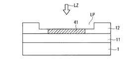
次に、第4のフォトリソグラフィー工程におけるリペア用薄膜部20の形成方法について、図22〜図26を用いてさらに説明する。
以下、本発明に係る電子装置の実施の形態2について図27〜図31を用いて説明する。なお、以下では、実施の形態1と異なる構成について説明し、共通する構成については説明を省略する。
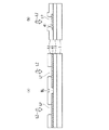
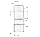
以上説明した実施の形態2においては、図30および図31に示したように、リペア用導電膜RLは、リペア用薄膜部20Aを完全に覆うように形成されていたが、図32に示すように、リペア用薄膜部20Aのうちリペア用導電膜RLで覆われない部分があるように、リペア用導電膜RLの堆積範囲を狭くしても良い。図32におけるC−C線での断面構成を図33に示す。図33に示されるようにソース配線41上はリペア用導電膜RLで覆われるが、リペア用薄膜部20Aの延在部には、リペア用導電膜RLで覆われない部分がある。
以下、本発明に係る電子装置の実施の形態3について図34〜図38を用いて説明する。なお、以下では、実施の形態1と異なる構成について説明し、共通する構成については説明を省略する。
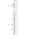
以上説明した実施の形態3においては、図37および図38に示したように、リペア用導電膜RLは、リペア用薄膜部20Bを完全に覆うように形成されていたが、図39に示すように、ソース配線41上はリペア用導電膜RLで覆われるが、リペア用薄膜部20Bのうちリペア用導電膜RLで覆われない部分があるように、リペア用導電膜RLの堆積範囲を狭くしても良い。図39におけるC−C線での断面構成を図40に示す。図40に示されるようにリペア用薄膜部20Bの延在部には、リペア用導電膜RLで覆われない部分がある。
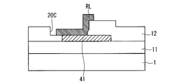
以下、本発明に係る電子装置の実施の形態4について図41〜図45を用いて説明する。なお、以下では、実施の形態1と異なる構成について説明し、共通する構成については説明を省略する。
以上説明した実施の形態4においては、図44および図45に示したように、リペア用導電膜RLは、2組のリペア用薄膜部20Cを完全に覆うように形成されていたが、図46に示すように、2組のリペア用薄膜部20Cのうちリペア用導電膜RLで覆われない部分があるように、リペア用導電膜RLの堆積範囲を狭くしても良い。図46におけるC−C線での断面構成を図47に示す。図47に示されるように、ソース配線41上はリペア用導電膜RLで覆われるが、リペア用薄膜部20Cの延在部には、リペア用導電膜RLで覆われない部分がある。リペア用導電膜RLの堆積範囲を狭くすることで、堆積に費やす時間を短縮でき、生産性が向上する。
以上説明した本発明に係る実施の形態1〜4においては、ソース配線41のリペアについて説明したが、本発明はソース配線のリペアへの適用に限定されるものではなく、ゲート配線21のリペアに適用しても良い。
以上説明した実施の形態5においては、ゲート配線21のリペアのために、ゲート配線21の幅方向の2つの端縁部のうち一方を越えるように形成されたリペア用薄膜部50を設けた構成を示したが、これに限定されるものではなく、実施の形態1、2、4およびそれぞれの変形例で説明した、それぞれのリペア用薄膜部の構成をゲート配線のリペアに適用しても同様の効果が得られる。
以上の説明においては本発明をTN方式の透過型の液晶表示装置に適用した構成について説明したが、本発明はFFS(Fringe Field Switching)方式、IPS(登録商標)方式、MVA(Multi-domain Vertical Alignment)方式などの液晶表示装置にも適用でき、また、透過型に限定されず、反射型、半透過型でも適用可能である。また、カラーフィルタを有さないフィールドシーケンシャル方式の液晶表示装置への適用も可能である。また、TFTもアモルファスシリコンTFTに限定されず、ポリシリコンTFT、低温ポリシリコンTFTなどを使用した液晶表示装置への適用も可能である。
Claims (12)
- 多層配線構造を有する電子装置であって、
下地層と、
前記下地層の上に配設されたパターニングされた配線と、
前記下地層および前記配線の上に形成された絶縁膜と、を備え、
前記絶縁膜は、
少なくとも前記配線の上方に対応する部分の膜厚が周囲より薄くなった、前記配線の接続リペアのための薄膜部を有する、電子装置。 - 前記薄膜部は、
前記薄膜部の前記配線の延在方向とは直交する方向の端縁部が、前記配線の幅方向の2つの端縁部より内側に収まるように設けられる、請求項1記載の電子装置。 - 前記薄膜部は、
前記薄膜部の前記配線の延在方向とは直交する方向の端縁部が、前記配線の幅方向の2つの端縁部の外側まで延在するように設けられる、請求項1記載の電子装置。 - 前記薄膜部は、
前記薄膜部の前記配線の延在方向とは直交する方向の端縁部の一方が、前記配線の幅方向の2つの端縁部のうち一方の外側まで延在するように設けられる、請求項1記載の電子装置。 - 前記薄膜部は、
前記薄膜部の前記配線の延在方向とは直交する方向の端縁部の一方が、前記配線の幅方向の2つの端縁部のうち一方の外側まで延在するように設けられた第1の薄膜部と、
前記薄膜部の前記配線の延在方向とは直交する方向の前記端縁部の他方が、前記配線の幅方向の2つの前記端縁部のうち他方の外側まで延在するように設けられた第2の薄膜部とで一組をなし、前記第1の薄膜部と前記第2の薄膜部とは間を開けて並べて設けられる、請求項1記載の電子装置。 - 前記薄膜部は、
前記配線の幅方向の前記端縁部を越えて延在する延在部の厚みが、前記配線の厚みと同程度に設定される、請求項3から請求項5の何れか1項に記載の電子装置。 - 前記薄膜部は、
前記配線の幅方向の前記端縁部を越えて延在する延在部の長さが、前記絶縁膜の厚み以上に設定される、請求項3から請求項5の何れか1項に記載の電子装置。 - 前記薄膜部は、
前記配線の延在方向に沿って複数設けられる、請求項1記載の電子装置。 - 請求項1記載の電子装置の製造方法であって、
前記絶縁膜に前記薄膜部を形成する工程は、
(a)写真製版工程により、前記絶縁膜上の前記薄膜部に対応する部分が凹部となって他の部分よりも薄くなったレジストパターンを形成する工程と、
(b)前記凹部が消滅して開口部が形成されるように前記レジストパターンの膜厚を減じる工程と、
(c)前記工程(b)の後、膜厚を減じた前記レジストパターンを用いて、エッチングにより、前記開口部下の前記絶縁膜の厚さを薄くして前記薄膜部を形成する工程と、を備える、電子装置の製造方法。 - 前記工程(a)は、
前記薄膜部に対応する部分が、露光光を全て透過させる透過部より透過率の低い半透過部となったグレートーンマスクを用いてフォトレジストを露光する工程を含む、請求項9記載の電子装置の製造方法。 - 請求項8記載の電子装置のリペア方法であって、
(a)前記配線の欠陥部分を挟む少なくとも2箇所の前記薄膜部にそれぞれレーザー光を照射して前記薄膜部の前記絶縁膜を除去し、前記配線に達する貫通孔を形成する工程と、
(b)前記貫通孔に露出する前記配線を少なくとも覆って、前記少なくとも2箇所の前記薄膜部に渡るように導体膜を形成して、前記欠陥部分を電気的に短絡する工程と、を備える、リペア方法。 - 前記工程(b)は、
レーザーCVDにより前記導体膜を形成する、請求項11記載のリペア方法。
Priority Applications (2)
| Application Number | Priority Date | Filing Date | Title |
|---|---|---|---|
| JP2015142652A JP6558990B2 (ja) | 2015-07-17 | 2015-07-17 | 電子装置およびその製造方法とリペア方法 |
| US15/198,534 US11988929B2 (en) | 2015-07-17 | 2016-06-30 | Electronic device, method of manufacturing same and method of repairing same |
Applications Claiming Priority (1)
| Application Number | Priority Date | Filing Date | Title |
|---|---|---|---|
| JP2015142652A JP6558990B2 (ja) | 2015-07-17 | 2015-07-17 | 電子装置およびその製造方法とリペア方法 |
Publications (3)
| Publication Number | Publication Date |
|---|---|
| JP2017028002A JP2017028002A (ja) | 2017-02-02 |
| JP2017028002A5 JP2017028002A5 (ja) | 2018-07-26 |
| JP6558990B2 true JP6558990B2 (ja) | 2019-08-14 |
Family
ID=57775823
Family Applications (1)
| Application Number | Title | Priority Date | Filing Date |
|---|---|---|---|
| JP2015142652A Active JP6558990B2 (ja) | 2015-07-17 | 2015-07-17 | 電子装置およびその製造方法とリペア方法 |
Country Status (2)
| Country | Link |
|---|---|
| US (1) | US11988929B2 (ja) |
| JP (1) | JP6558990B2 (ja) |
Families Citing this family (5)
| Publication number | Priority date | Publication date | Assignee | Title |
|---|---|---|---|---|
| CN104570415B (zh) * | 2014-12-05 | 2017-07-18 | 合肥鑫晟光电科技有限公司 | 金属线的修复方法及修复设备 |
| WO2017170099A1 (ja) * | 2016-03-30 | 2017-10-05 | シャープ株式会社 | 液晶パネルの製造方法 |
| CN105867689B (zh) * | 2016-04-07 | 2018-06-05 | 京东方科技集团股份有限公司 | 一种触控显示基板的制作方法及触控显示装置的阵列基板 |
| CN109164654B (zh) * | 2018-09-27 | 2021-10-22 | 京东方科技集团股份有限公司 | 一种阵列基板及其制作方法、显示装置 |
| GB202010407D0 (en) * | 2020-07-07 | 2020-08-19 | Univ Court Univ Of Glasgow | Micromachined mechcahnical part and methods of fabrication thereof |
Family Cites Families (24)
| Publication number | Priority date | Publication date | Assignee | Title |
|---|---|---|---|---|
| JP2619435B2 (ja) * | 1987-11-27 | 1997-06-11 | 株式会社日立製作所 | イオンビーム加工方法 |
| US5164565A (en) * | 1991-04-18 | 1992-11-17 | Photon Dynamics, Inc. | Laser-based system for material deposition and removal |
| JPH103088A (ja) * | 1996-06-18 | 1998-01-06 | Sharp Corp | アクティブマトリクス基板 |
| JP3474415B2 (ja) * | 1997-11-27 | 2003-12-08 | 株式会社東芝 | 半導体装置 |
| JPH11190858A (ja) | 1997-12-25 | 1999-07-13 | Sharp Corp | アクティブマトリクス型表示装置及びその製造方法 |
| JP2000012541A (ja) * | 1998-06-19 | 2000-01-14 | Toshiba Corp | 半導体装置の製造方法 |
| US7084016B1 (en) * | 1998-07-17 | 2006-08-01 | Semiconductor Energy Laboratory Co., Ltd. | Crystalline semiconductor thin film, method of fabricating the same, semiconductor device, and method of fabricating the same |
| US6180516B1 (en) * | 1998-11-05 | 2001-01-30 | United Microelectronics Corp, | Method of fabricating a dual damascene structure |
| JP3506369B2 (ja) * | 1999-07-06 | 2004-03-15 | 松下電器産業株式会社 | 半導体集積回路装置及びその製造方法 |
| JP2001324725A (ja) * | 2000-05-12 | 2001-11-22 | Hitachi Ltd | 液晶表示装置およびその製造方法 |
| JP3705156B2 (ja) * | 2001-06-04 | 2005-10-12 | 株式会社日立製作所 | 平面ディスプレイパネルの配線欠陥修正方法 |
| JP2004054069A (ja) * | 2002-07-23 | 2004-02-19 | Advanced Display Inc | 表示装置及び表示装置の断線修復方法 |
| US7112288B2 (en) * | 2002-08-13 | 2006-09-26 | Texas Instruments Incorporated | Methods for inspection sample preparation |
| JP4202077B2 (ja) * | 2002-09-11 | 2008-12-24 | パナソニック株式会社 | ヒューズの切断方法 |
| JP2004266224A (ja) * | 2003-03-04 | 2004-09-24 | Seiko Epson Corp | 半導体装置及びその製造方法 |
| JP2005109223A (ja) * | 2003-09-30 | 2005-04-21 | Sanyo Electric Co Ltd | 半導体装置および表示装置 |
| JP4247897B2 (ja) | 2003-12-11 | 2009-04-02 | シャープ株式会社 | 液晶表示パネルおよび液晶表示パネルの製造方法 |
| JP4342969B2 (ja) | 2004-01-30 | 2009-10-14 | 三菱電機株式会社 | 表示装置とその製造方法 |
| JP4100351B2 (ja) * | 2004-02-09 | 2008-06-11 | セイコーエプソン株式会社 | 薄膜トランジスタの製造方法 |
| SG114747A1 (en) * | 2004-02-25 | 2005-09-28 | Mitsubishi Gas Chemical Co | Etching composition for laminated film including reflective electrode and method for forming laminated wiring structure |
| JP4405488B2 (ja) * | 2006-08-30 | 2010-01-27 | 株式会社東芝 | 半導体装置及び半導体装置の製造方法 |
| JP4930095B2 (ja) * | 2007-02-22 | 2012-05-09 | 富士通株式会社 | ウエットエッチング方法および半導体装置の製造方法 |
| CN100501507C (zh) * | 2007-07-09 | 2009-06-17 | 昆山龙腾光电有限公司 | 液晶显示面板及其制造方法和包含其的装置 |
| JP5949257B2 (ja) * | 2012-07-19 | 2016-07-06 | 株式会社ソシオネクスト | 配線加工方法 |
-
2015
- 2015-07-17 JP JP2015142652A patent/JP6558990B2/ja active Active
-
2016
- 2016-06-30 US US15/198,534 patent/US11988929B2/en active Active
Also Published As
| Publication number | Publication date |
|---|---|
| US20170017131A1 (en) | 2017-01-19 |
| JP2017028002A (ja) | 2017-02-02 |
| US11988929B2 (en) | 2024-05-21 |
Similar Documents
| Publication | Publication Date | Title |
|---|---|---|
| JP4777334B2 (ja) | 液晶表示装置及びその製造方法 | |
| JP6181093B2 (ja) | 液晶表示装置アレイ基板及びその製造方法 | |
| JP4299113B2 (ja) | 液晶表示装置用アレイ基板の製造方法 | |
| JP6558990B2 (ja) | 電子装置およびその製造方法とリペア方法 | |
| KR101006434B1 (ko) | 박막 트랜지스터 표시판 및 이를 포함하는 액정 표시장치의 수리 방법 | |
| KR101248005B1 (ko) | 어레이 기판 및 그의 제조방법 | |
| JP4622532B2 (ja) | 表示装置および表示装置の欠陥修復方法 | |
| JP6278633B2 (ja) | 薄膜トランジスタアレイ基板およびその製造方法、並びに、液晶表示装置およびその製造方法 | |
| KR20090112356A (ko) | 액정표시장치용 어레이 기판과 그 제조방법 | |
| JP3884625B2 (ja) | 液晶表示装置及びその欠陥修復方法 | |
| KR102383446B1 (ko) | 표시 기판의 리페어 방법 및 이에 의해 리페어된 표시 기판 | |
| JP4184730B2 (ja) | 液晶表示装置用基板の欠陥修復方法及びそれを含む製造方法 | |
| WO2006126405A1 (ja) | 液晶表示装置用基板、液晶表示装置用基板の製造方法、液晶表示装置および液晶表示装置の製造方法 | |
| US20070097282A1 (en) | Thin film multilayer substrate, manufacturing method thereof, and liquid crystal display having thin film multilayer substrate | |
| KR20070036915A (ko) | 박막 트랜지스터 기판, 액정 표시 장치 및 그 제조 방법 | |
| KR101086121B1 (ko) | 수평전계방식 액정표시소자 및 그 제조방법 | |
| JP2021026166A (ja) | 電子素子と液晶表示装置 | |
| KR100835171B1 (ko) | 액정표시장치용 어레이기판과 그 제조방법 | |
| KR20020053575A (ko) | 액정표시장치와 그 제조방법 | |
| KR100866977B1 (ko) | 리페어 구조를 가지는 액정표시장치용 어레이 기판 | |
| JP6425676B2 (ja) | 表示装置の製造方法 | |
| US20190310506A1 (en) | Liquid crystal display apparatus and method for manufacturing liquid crystal display apparatus | |
| KR20050014059A (ko) | 박막 트랜지스터 표시판 및 이를 포함하는 액정 표시장치의 수리 방법 | |
| KR101012796B1 (ko) | 액정 표시 장치 | |
| KR20050005673A (ko) | 박막 트랜지스터 표시판 및 이를 포함하는 액정 표시장치의 수리 방법 |
Legal Events
| Date | Code | Title | Description |
|---|---|---|---|
| A521 | Request for written amendment filed |
Free format text: JAPANESE INTERMEDIATE CODE: A523 Effective date: 20180615 |
|
| A621 | Written request for application examination |
Free format text: JAPANESE INTERMEDIATE CODE: A621 Effective date: 20180615 |
|
| A977 | Report on retrieval |
Free format text: JAPANESE INTERMEDIATE CODE: A971007 Effective date: 20190226 |
|
| A131 | Notification of reasons for refusal |
Free format text: JAPANESE INTERMEDIATE CODE: A131 Effective date: 20190402 |
|
| A521 | Request for written amendment filed |
Free format text: JAPANESE INTERMEDIATE CODE: A523 Effective date: 20190524 |
|
| TRDD | Decision of grant or rejection written | ||
| A01 | Written decision to grant a patent or to grant a registration (utility model) |
Free format text: JAPANESE INTERMEDIATE CODE: A01 Effective date: 20190618 |
|
| A61 | First payment of annual fees (during grant procedure) |
Free format text: JAPANESE INTERMEDIATE CODE: A61 Effective date: 20190716 |
|
| R150 | Certificate of patent or registration of utility model |
Ref document number: 6558990 Country of ref document: JP Free format text: JAPANESE INTERMEDIATE CODE: R150 |
|
| R250 | Receipt of annual fees |
Free format text: JAPANESE INTERMEDIATE CODE: R250 |
|
| R250 | Receipt of annual fees |
Free format text: JAPANESE INTERMEDIATE CODE: R250 |
|
| R250 | Receipt of annual fees |
Free format text: JAPANESE INTERMEDIATE CODE: R250 |


