JP6232960B2 - 自動二輪車の吸気ダクト装置 - Google Patents
自動二輪車の吸気ダクト装置 Download PDFInfo
- Publication number
- JP6232960B2 JP6232960B2 JP2013238068A JP2013238068A JP6232960B2 JP 6232960 B2 JP6232960 B2 JP 6232960B2 JP 2013238068 A JP2013238068 A JP 2013238068A JP 2013238068 A JP2013238068 A JP 2013238068A JP 6232960 B2 JP6232960 B2 JP 6232960B2
- Authority
- JP
- Japan
- Prior art keywords
- intake duct
- body frame
- head pipe
- vehicle body
- air cleaner
- Prior art date
- Legal status (The legal status is an assumption and is not a legal conclusion. Google has not performed a legal analysis and makes no representation as to the accuracy of the status listed.)
- Active
Links
Images


Classifications
-
- B—PERFORMING OPERATIONS; TRANSPORTING
- B60—VEHICLES IN GENERAL
- B60K—ARRANGEMENT OR MOUNTING OF PROPULSION UNITS OR OF TRANSMISSIONS IN VEHICLES; ARRANGEMENT OR MOUNTING OF PLURAL DIVERSE PRIME-MOVERS IN VEHICLES; AUXILIARY DRIVES FOR VEHICLES; INSTRUMENTATION OR DASHBOARDS FOR VEHICLES; ARRANGEMENTS IN CONNECTION WITH COOLING, AIR INTAKE, GAS EXHAUST OR FUEL SUPPLY OF PROPULSION UNITS IN VEHICLES
- B60K13/00—Arrangement in connection with combustion air intake or gas exhaust of propulsion units
- B60K13/02—Arrangement in connection with combustion air intake or gas exhaust of propulsion units concerning intake
-
- B—PERFORMING OPERATIONS; TRANSPORTING
- B62—LAND VEHICLES FOR TRAVELLING OTHERWISE THAN ON RAILS
- B62K—CYCLES; CYCLE FRAMES; CYCLE STEERING DEVICES; RIDER-OPERATED TERMINAL CONTROLS SPECIALLY ADAPTED FOR CYCLES; CYCLE AXLE SUSPENSIONS; CYCLE SIDE-CARS, FORECARS, OR THE LIKE
- B62K11/00—Motorcycles, engine-assisted cycles or motor scooters with one or two wheels
- B62K11/02—Frames
- B62K11/04—Frames characterised by the engine being between front and rear wheels
- B62K11/06—Frames characterised by the engine being between front and rear wheels the frame being of single-beam type
-
- B—PERFORMING OPERATIONS; TRANSPORTING
- B62—LAND VEHICLES FOR TRAVELLING OTHERWISE THAN ON RAILS
- B62K—CYCLES; CYCLE FRAMES; CYCLE STEERING DEVICES; RIDER-OPERATED TERMINAL CONTROLS SPECIALLY ADAPTED FOR CYCLES; CYCLE AXLE SUSPENSIONS; CYCLE SIDE-CARS, FORECARS, OR THE LIKE
- B62K19/00—Cycle frames
- B62K19/30—Frame parts shaped to receive other cycle parts or accessories
- B62K19/32—Steering heads
-
- F—MECHANICAL ENGINEERING; LIGHTING; HEATING; WEAPONS; BLASTING
- F02—COMBUSTION ENGINES; HOT-GAS OR COMBUSTION-PRODUCT ENGINE PLANTS
- F02M—SUPPLYING COMBUSTION ENGINES IN GENERAL WITH COMBUSTIBLE MIXTURES OR CONSTITUENTS THEREOF
- F02M35/00—Combustion-air cleaners, air intakes, intake silencers, or induction systems specially adapted for, or arranged on, internal-combustion engines
- F02M35/10—Air intakes; Induction systems
- F02M35/10006—Air intakes; Induction systems characterised by the position of elements of the air intake system in direction of the air intake flow, i.e. between ambient air inlet and supply to the combustion chamber
- F02M35/10013—Means upstream of the air filter; Connection to the ambient air
-
- F—MECHANICAL ENGINEERING; LIGHTING; HEATING; WEAPONS; BLASTING
- F02—COMBUSTION ENGINES; HOT-GAS OR COMBUSTION-PRODUCT ENGINE PLANTS
- F02M—SUPPLYING COMBUSTION ENGINES IN GENERAL WITH COMBUSTIBLE MIXTURES OR CONSTITUENTS THEREOF
- F02M35/00—Combustion-air cleaners, air intakes, intake silencers, or induction systems specially adapted for, or arranged on, internal-combustion engines
- F02M35/10—Air intakes; Induction systems
- F02M35/10091—Air intakes; Induction systems characterised by details of intake ducts: shapes; connections; arrangements
- F02M35/10144—Connections of intake ducts to each other or to another device
-
- F—MECHANICAL ENGINEERING; LIGHTING; HEATING; WEAPONS; BLASTING
- F02—COMBUSTION ENGINES; HOT-GAS OR COMBUSTION-PRODUCT ENGINE PLANTS
- F02M—SUPPLYING COMBUSTION ENGINES IN GENERAL WITH COMBUSTIBLE MIXTURES OR CONSTITUENTS THEREOF
- F02M35/00—Combustion-air cleaners, air intakes, intake silencers, or induction systems specially adapted for, or arranged on, internal-combustion engines
- F02M35/16—Combustion-air cleaners, air intakes, intake silencers, or induction systems specially adapted for, or arranged on, internal-combustion engines characterised by use in vehicles
- F02M35/161—Arrangement of the air intake system in the engine compartment, e.g. with respect to the bonnet or the vehicle front face
-
- F—MECHANICAL ENGINEERING; LIGHTING; HEATING; WEAPONS; BLASTING
- F02—COMBUSTION ENGINES; HOT-GAS OR COMBUSTION-PRODUCT ENGINE PLANTS
- F02M—SUPPLYING COMBUSTION ENGINES IN GENERAL WITH COMBUSTIBLE MIXTURES OR CONSTITUENTS THEREOF
- F02M35/00—Combustion-air cleaners, air intakes, intake silencers, or induction systems specially adapted for, or arranged on, internal-combustion engines
- F02M35/16—Combustion-air cleaners, air intakes, intake silencers, or induction systems specially adapted for, or arranged on, internal-combustion engines characterised by use in vehicles
- F02M35/162—Motorcycles; All-terrain vehicles, e.g. quads, snowmobiles; Small vehicles, e.g. forklifts
Description
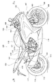
図1は、本発明の適用例としての自動二輪車100の側面図である。先ず、図1を用いて、自動二輪車100の全体構成について説明する。なお、図1を含め、以下の説明で用いる図においては、必要に応じて車両の前方を矢印Frにより、車両の後方を矢印Rrにより示し、また、車両の側方右側を矢印Rにより、車両の側方左側を矢印Lにより示す。
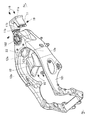
このように吸気ダクト10を車体フレーム101と別体に形成することで、車体フレーム101自体を変更することなくそのままで、吸気ダクト10の断面積を変化させることができる。図6に示したように公道走行車両ではステアリング切れ角θが大きく、且つフォークピッチpが狭く、吸気ダクト10の断面積としては小さくなる。また、レース用車両等ではステアリング切れ角θが小さく、且つフォークピッチpが広く、吸気ダクト10の断面積としては大きくなる。その際、吸気ダクト10側の断面積の調整のみで異なる車種に有効に対応することが可能になる。
上記実施形態において、エンジンユニット116は4気筒以外の多気筒エンジン、即ち例えば並列2気筒あるいは3気筒であっても同様に適用可能である。
Claims (9)
- ステアリングヘッドパイプから車両後方へやや下方に向けて延設した車体フレームにエンジンを搭載し、前記エンジンの上方にエアクリーナが配置されると共に、カウリング前面から取り込んだ走行風を前記ステアリングヘッドパイプの両側面を通過するように前記エアクリーナへと導く吸気ダクトを備えた自動二輪車において、
前記吸気ダクトは前記車体フレームとは別部品で構成され、前吸気ダクト及び後吸気ダクトに2分割され、
前記前吸気ダクトは、単一の前部開口から後方へ延出して左右一対の後部開口が二股状に分岐するように分岐部位が形成され、
前記後吸気ダクトは、二股状に分岐した左右一対の前部開口が後方へ延出して単一の後部開口へと合流するように合流部位が形成され、
これら一対の前記前吸気ダクトの後部開口と前記後吸気ダクトの前部開口同士が接続され、前記前吸気ダクト及び前記後吸気ダクトは、前記ステアリングヘッドパイプを前後から包むように前記車体フレームに締付け固定されていることを特徴とする自動二輪車の吸気ダクト装置。 - 前記前吸気ダクトは前部吸気ダクトを介して、前記カウリング前面に開設された空気取込み口に連通され、取り込まれた走行風は前記ステアリングヘッドパイプの両側面を通過して、前記後吸気ダクトの後部に接続された前記エアクリーナに送風されることを特徴とする請求項1に記載の自動二輪車の吸気ダクト装置。
- 前記車体フレームは前記ステアリングヘッドパイプの上下のステアリングレース取付面と、前記ステアリングレース取付面を支える支柱部と、ツインスパー型ボディフレームによって車体前後方向に貫通する左右の穴部とが形成され、
前記支柱部は、前側に第1締結部を設け、後側に第2締結部を設け、これらの締結部を介して前記支柱部の前方及び後方に前記前吸気ダクト及び前記後吸気ダクトをそれぞれ締結することを特徴とする請求項1又は2に記載の自動二輪車の吸気ダクト装置。 - 前記前吸気ダクトはその内側が前記支柱部の形状に沿うように該支柱部の前側で左右に分岐すると共に、前記後吸気ダクトは前記支柱部の後側で合流し、前記エアクリーナとの接続部付近が一体的に連結される吸入口形状となっていることを特徴とする請求項3に記載の自動二輪車の吸気ダクト装置。
- 前記支柱部は車体前後方向を長辺としたオーバル形状とし、その長辺の前側に前記第1締結部を設け、後側に前記第2締結部を設けることを特徴とする請求項4に記載の自動二輪車の吸気ダクト装置。
- 前記前吸気ダクトは前記分岐部位にて前記第1締結部に、前記後吸気ダクトは前記合流部位にて前記第2締結部に、それぞれ締結固定されることを特徴とする請求項3から5の何れか1項に記載の自動二輪車の吸気ダクト装置。
- ステアリングヘッドパイプから車両後方へやや下方に向けて延設した車体フレームにエンジンを搭載し、前記エンジンの上方にエアクリーナが配置されると共に、カウリング前面から取り込んだ走行風を前記ステアリングヘッドパイプの両側面を通過するように前記エアクリーナへと導く吸気ダクトを備えた自動二輪車において、
前記吸気ダクトは前記車体フレームとは別部品で構成され、前記ステアリングヘッドパイプを前後から包むように前吸気ダクト及び後吸気ダクトに2分割され、
前記車体フレームは前記ステアリングヘッドパイプの上下のステアリングレース取付面と、前記ステアリングレース取付面を支える支柱部とが形成され、
前記支柱部は、前側に第1締結部を設け、後側に第2締結部を設け、これらの締結部を介して前記支柱部の前方及び後方に前記前吸気ダクト及び前記後吸気ダクトをそれぞれ締結することを特徴とする自動二輪車の吸気ダクト装置。 - 前記支柱部は車体前後方向を長辺としたオーバル形状とし、その長辺の前側に第1締結部を設け、後側に第2締結部を設けることを特徴とする請求項7に記載の自動二輪車の吸気ダクト装置。
- 前記前吸気ダクトまたは前記後吸気ダクトは、ダクト内側から前記車体フレームに締付け固定されていることを特徴とする請求項1から8の何れか1項に記載の自動二輪車の吸気ダクト装置。
Priority Applications (5)
| Application Number | Priority Date | Filing Date | Title |
|---|---|---|---|
| JP2013238068A JP6232960B2 (ja) | 2013-11-18 | 2013-11-18 | 自動二輪車の吸気ダクト装置 |
| IN2907DE2014 IN2014DE02907A (ja) | 2013-11-18 | 2014-10-11 | |
| US14/539,090 US9370996B2 (en) | 2013-11-18 | 2014-11-12 | Intake duct device of motorcycle |
| CN201410658072.5A CN104653360B (zh) | 2013-11-18 | 2014-11-18 | 摩托车的进气管装置 |
| DE102014116817.8A DE102014116817B4 (de) | 2013-11-18 | 2014-11-18 | Einlasskanalvorrichtung für ein Motorrad |
Applications Claiming Priority (1)
| Application Number | Priority Date | Filing Date | Title |
|---|---|---|---|
| JP2013238068A JP6232960B2 (ja) | 2013-11-18 | 2013-11-18 | 自動二輪車の吸気ダクト装置 |
Publications (2)
| Publication Number | Publication Date |
|---|---|
| JP2015098220A JP2015098220A (ja) | 2015-05-28 |
| JP6232960B2 true JP6232960B2 (ja) | 2017-11-22 |
Family
ID=53172162
Family Applications (1)
| Application Number | Title | Priority Date | Filing Date |
|---|---|---|---|
| JP2013238068A Active JP6232960B2 (ja) | 2013-11-18 | 2013-11-18 | 自動二輪車の吸気ダクト装置 |
Country Status (5)
| Country | Link |
|---|---|
| US (1) | US9370996B2 (ja) |
| JP (1) | JP6232960B2 (ja) |
| CN (1) | CN104653360B (ja) |
| DE (1) | DE102014116817B4 (ja) |
| IN (1) | IN2014DE02907A (ja) |
Families Citing this family (7)
| Publication number | Priority date | Publication date | Assignee | Title |
|---|---|---|---|---|
| JP6120914B2 (ja) * | 2015-07-15 | 2017-04-26 | 本田技研工業株式会社 | 車両のカウルステー構造 |
| JP6455981B2 (ja) * | 2015-09-28 | 2019-01-23 | 本田技研工業株式会社 | 鞍乗型車両のレゾネータ構造 |
| JP6333873B2 (ja) | 2016-03-03 | 2018-05-30 | 本田技研工業株式会社 | 鞍乗り型車両のエアクリーナ構造 |
| US10352281B2 (en) * | 2016-07-08 | 2019-07-16 | Kawasaki Jukogyo Kabushiki Kaisha | Manufacturing method of head box of motorcycle, and air-intake device of motorcycle |
| DE102016220301B3 (de) * | 2016-10-18 | 2017-06-29 | Bayerische Motoren Werke Aktiengesellschaft | Motorradansaugluftführung für einen Motorradmotor |
| DE102016222441B4 (de) * | 2016-11-16 | 2019-09-12 | Bayerische Motoren Werke Aktiengesellschaft | Motorradansaugluftführung für einen Motorradverbrennungsmotor |
| US10843759B2 (en) * | 2017-10-25 | 2020-11-24 | Yamaha Hatsudoki Kabushiki Kaisha | Vehicle |
Family Cites Families (14)
| Publication number | Priority date | Publication date | Assignee | Title |
|---|---|---|---|---|
| JP2558687Y2 (ja) * | 1991-10-31 | 1997-12-24 | 川崎重工業株式会社 | 自動二輪車の吸気通路 |
| US5577570A (en) * | 1992-04-09 | 1996-11-26 | Yamaha Hatsudoki Kabushiki Kaisha | Wind introducing system for motorcycle |
| JP2001071968A (ja) * | 1999-09-05 | 2001-03-21 | Honda Motor Co Ltd | 自動2輪車の吸気通路構造 |
| JP3122437B1 (ja) * | 1999-09-21 | 2001-01-09 | 川崎重工業株式会社 | 車両用エンジンの吸気装置 |
| JP3723792B2 (ja) * | 2002-09-13 | 2005-12-07 | 川崎重工業株式会社 | 車両用エンジンの空気取入装置 |
| JP4340500B2 (ja) * | 2003-09-09 | 2009-10-07 | 川崎重工業株式会社 | 自動二輪車の吸気装置 |
| JP4490203B2 (ja) * | 2004-08-09 | 2010-06-23 | 川崎重工業株式会社 | 自動二輪車の吸気装置 |
| JP4444868B2 (ja) * | 2005-03-31 | 2010-03-31 | 本田技研工業株式会社 | 吸気ダクト構造 |
| JP2007145130A (ja) * | 2005-11-25 | 2007-06-14 | Yamaha Motor Co Ltd | 自動二輪車 |
| JP4745175B2 (ja) | 2005-12-28 | 2011-08-10 | 本田技研工業株式会社 | 自動二輪車 |
| ATE473909T1 (de) * | 2008-03-19 | 2010-07-15 | Kwang Yang Motor Co | Lufteinlasssystem zur zufuhr von verbrennungsluft in einen motor eines motorrads |
| JP5271696B2 (ja) * | 2008-12-26 | 2013-08-21 | ヤマハ発動機株式会社 | 鞍乗型車両 |
| JP2013238068A (ja) | 2012-05-16 | 2013-11-28 | Daiken Corp | 耐力壁構造 |
| JP5965270B2 (ja) * | 2012-09-28 | 2016-08-03 | 本田技研工業株式会社 | 自動二輪車における前部導風構造 |
-
2013
- 2013-11-18 JP JP2013238068A patent/JP6232960B2/ja active Active
-
2014
- 2014-10-11 IN IN2907DE2014 patent/IN2014DE02907A/en unknown
- 2014-11-12 US US14/539,090 patent/US9370996B2/en active Active
- 2014-11-18 DE DE102014116817.8A patent/DE102014116817B4/de active Active
- 2014-11-18 CN CN201410658072.5A patent/CN104653360B/zh active Active
Also Published As
| Publication number | Publication date |
|---|---|
| US9370996B2 (en) | 2016-06-21 |
| CN104653360A (zh) | 2015-05-27 |
| DE102014116817A1 (de) | 2015-05-21 |
| CN104653360B (zh) | 2017-04-26 |
| DE102014116817B4 (de) | 2016-08-04 |
| US20150136511A1 (en) | 2015-05-21 |
| IN2014DE02907A (ja) | 2015-07-24 |
| JP2015098220A (ja) | 2015-05-28 |
Similar Documents
| Publication | Publication Date | Title |
|---|---|---|
| JP6232960B2 (ja) | 自動二輪車の吸気ダクト装置 | |
| JP5889685B2 (ja) | 鞍乗り型車両のキャニスター配置構造 | |
| JP6447383B2 (ja) | 鞍乗型車両の吸気構造 | |
| JP4829641B2 (ja) | 自動二輪車 | |
| US20140174394A1 (en) | Intake passage structure for vehicle | |
| US9156513B2 (en) | Front cowl stay attachment structure for saddle-ride type vehicle | |
| JP6191250B2 (ja) | 自動二輪車のエアクリーナ構造 | |
| EP2289787B1 (en) | Saddle-ride type vehicle | |
| JP6492940B2 (ja) | 鞍乗型車両 | |
| JP7082561B2 (ja) | 鞍乗り型車両の吸気構造 | |
| JP5292512B2 (ja) | 鞍乗り型車両の吸気系の配置構造 | |
| JP7038035B2 (ja) | 鞍乗り型車両の吸気構造 | |
| JP5625631B2 (ja) | エンジンのスロットル装置 | |
| JP5227839B2 (ja) | 鞍乗り型車両の吸気装置構造 | |
| JP4351584B2 (ja) | 自動二輪車の吸気装置 | |
| US9097223B2 (en) | Air cleaner structure of motorcycle | |
| JP6322909B2 (ja) | 内燃機関の燃料供給装置 | |
| JP5946357B2 (ja) | 鞍乗型車両 | |
| JP2010019200A (ja) | エンジンの燃料噴射装置 | |
| WO2010038586A1 (ja) | 自動二輪車のエンジン懸架構造 | |
| JP6269081B2 (ja) | インジェクタ取付構造 | |
| JP2014069715A (ja) | 自動二輪車用吸気装置 | |
| JP2019151148A (ja) | エンジンハンガ構造 | |
| JP6851409B2 (ja) | 鞍乗型車両用内燃機関 | |
| JP5720675B2 (ja) | エンジンの燃料噴射装置 |
Legal Events
| Date | Code | Title | Description |
|---|---|---|---|
| A621 | Written request for application examination |
Free format text: JAPANESE INTERMEDIATE CODE: A621 Effective date: 20161026 |
|
| A977 | Report on retrieval |
Free format text: JAPANESE INTERMEDIATE CODE: A971007 Effective date: 20170427 |
|
| A131 | Notification of reasons for refusal |
Free format text: JAPANESE INTERMEDIATE CODE: A131 Effective date: 20170509 |
|
| A521 | Request for written amendment filed |
Free format text: JAPANESE INTERMEDIATE CODE: A523 Effective date: 20170704 |
|
| TRDD | Decision of grant or rejection written | ||
| A01 | Written decision to grant a patent or to grant a registration (utility model) |
Free format text: JAPANESE INTERMEDIATE CODE: A01 Effective date: 20170926 |
|
| A61 | First payment of annual fees (during grant procedure) |
Free format text: JAPANESE INTERMEDIATE CODE: A61 Effective date: 20171009 |
|
| R151 | Written notification of patent or utility model registration |
Ref document number: 6232960 Country of ref document: JP Free format text: JAPANESE INTERMEDIATE CODE: R151 |