JP5754398B2 - 半導体装置 - Google Patents
半導体装置 Download PDFInfo
- Publication number
- JP5754398B2 JP5754398B2 JP2012053061A JP2012053061A JP5754398B2 JP 5754398 B2 JP5754398 B2 JP 5754398B2 JP 2012053061 A JP2012053061 A JP 2012053061A JP 2012053061 A JP2012053061 A JP 2012053061A JP 5754398 B2 JP5754398 B2 JP 5754398B2
- Authority
- JP
- Japan
- Prior art keywords
- comb teeth
- electrode
- internal electrode
- semiconductor device
- semiconductor element
- Prior art date
- Legal status (The legal status is an assumption and is not a legal conclusion. Google has not performed a legal analysis and makes no representation as to the accuracy of the status listed.)
- Active
Links
- 239000004065 semiconductor Substances 0.000 title claims description 117
- 239000003990 capacitor Substances 0.000 claims description 32
- 239000011347 resin Substances 0.000 claims description 25
- 229920005989 resin Polymers 0.000 claims description 25
- 244000126211 Hericium coralloides Species 0.000 claims description 12
- 238000001816 cooling Methods 0.000 claims description 8
- 239000000919 ceramic Substances 0.000 claims description 5
- 230000008878 coupling Effects 0.000 claims description 4
- 238000010168 coupling process Methods 0.000 claims description 4
- 238000005859 coupling reaction Methods 0.000 claims description 4
- 239000004020 conductor Substances 0.000 claims description 3
- 229910000679 solder Inorganic materials 0.000 description 10
- 239000000463 material Substances 0.000 description 6
- 230000017525 heat dissipation Effects 0.000 description 3
- 238000010586 diagram Methods 0.000 description 2
- 230000000694 effects Effects 0.000 description 2
- 238000009434 installation Methods 0.000 description 2
- 238000000034 method Methods 0.000 description 2
- 239000000758 substrate Substances 0.000 description 2
- 239000003989 dielectric material Substances 0.000 description 1
- 229910010272 inorganic material Inorganic materials 0.000 description 1
- 239000011147 inorganic material Substances 0.000 description 1
- 239000012212 insulator Substances 0.000 description 1
- 239000011368 organic material Substances 0.000 description 1
- 238000001721 transfer moulding Methods 0.000 description 1
Images


Classifications
-
- H—ELECTRICITY
- H01—ELECTRIC ELEMENTS
- H01L—SEMICONDUCTOR DEVICES NOT COVERED BY CLASS H10
- H01L28/00—Passive two-terminal components without a potential-jump or surface barrier for integrated circuits; Details thereof; Multistep manufacturing processes therefor
- H01L28/40—Capacitors
- H01L28/60—Electrodes
- H01L28/82—Electrodes with an enlarged surface, e.g. formed by texturisation
-
- H—ELECTRICITY
- H01—ELECTRIC ELEMENTS
- H01L—SEMICONDUCTOR DEVICES NOT COVERED BY CLASS H10
- H01L29/00—Semiconductor devices adapted for rectifying, amplifying, oscillating or switching, or capacitors or resistors with at least one potential-jump barrier or surface barrier, e.g. PN junction depletion layer or carrier concentration layer; Details of semiconductor bodies or of electrodes thereof ; Multistep manufacturing processes therefor
- H01L29/66—Types of semiconductor device ; Multistep manufacturing processes therefor
- H01L29/86—Types of semiconductor device ; Multistep manufacturing processes therefor controllable only by variation of the electric current supplied, or only the electric potential applied, to one or more of the electrodes carrying the current to be rectified, amplified, oscillated or switched
- H01L29/92—Capacitors with potential-jump barrier or surface barrier
-
- H—ELECTRICITY
- H01—ELECTRIC ELEMENTS
- H01G—CAPACITORS; CAPACITORS, RECTIFIERS, DETECTORS, SWITCHING DEVICES OR LIGHT-SENSITIVE DEVICES, OF THE ELECTROLYTIC TYPE
- H01G4/00—Fixed capacitors; Processes of their manufacture
- H01G4/002—Details
- H01G4/228—Terminals
- H01G4/232—Terminals electrically connecting two or more layers of a stacked or rolled capacitor
-
- H—ELECTRICITY
- H01—ELECTRIC ELEMENTS
- H01G—CAPACITORS; CAPACITORS, RECTIFIERS, DETECTORS, SWITCHING DEVICES OR LIGHT-SENSITIVE DEVICES, OF THE ELECTROLYTIC TYPE
- H01G4/00—Fixed capacitors; Processes of their manufacture
- H01G4/30—Stacked capacitors
-
- H—ELECTRICITY
- H01—ELECTRIC ELEMENTS
- H01L—SEMICONDUCTOR DEVICES NOT COVERED BY CLASS H10
- H01L23/00—Details of semiconductor or other solid state devices
- H01L23/48—Arrangements for conducting electric current to or from the solid state body in operation, e.g. leads, terminal arrangements ; Selection of materials therefor
- H01L23/488—Arrangements for conducting electric current to or from the solid state body in operation, e.g. leads, terminal arrangements ; Selection of materials therefor consisting of soldered or bonded constructions
- H01L23/495—Lead-frames or other flat leads
- H01L23/49541—Geometry of the lead-frame
- H01L23/49562—Geometry of the lead-frame for devices being provided for in H01L29/00
-
- H—ELECTRICITY
- H01—ELECTRIC ELEMENTS
- H01L—SEMICONDUCTOR DEVICES NOT COVERED BY CLASS H10
- H01L23/00—Details of semiconductor or other solid state devices
- H01L23/48—Arrangements for conducting electric current to or from the solid state body in operation, e.g. leads, terminal arrangements ; Selection of materials therefor
- H01L23/488—Arrangements for conducting electric current to or from the solid state body in operation, e.g. leads, terminal arrangements ; Selection of materials therefor consisting of soldered or bonded constructions
- H01L23/495—Lead-frames or other flat leads
- H01L23/49589—Capacitor integral with or on the leadframe
-
- H—ELECTRICITY
- H01—ELECTRIC ELEMENTS
- H01L—SEMICONDUCTOR DEVICES NOT COVERED BY CLASS H10
- H01L23/00—Details of semiconductor or other solid state devices
- H01L23/58—Structural electrical arrangements for semiconductor devices not otherwise provided for, e.g. in combination with batteries
- H01L23/64—Impedance arrangements
- H01L23/642—Capacitive arrangements
-
- H—ELECTRICITY
- H01—ELECTRIC ELEMENTS
- H01L—SEMICONDUCTOR DEVICES NOT COVERED BY CLASS H10
- H01L24/00—Arrangements for connecting or disconnecting semiconductor or solid-state bodies; Methods or apparatus related thereto
- H01L24/01—Means for bonding being attached to, or being formed on, the surface to be connected, e.g. chip-to-package, die-attach, "first-level" interconnects; Manufacturing methods related thereto
- H01L24/26—Layer connectors, e.g. plate connectors, solder or adhesive layers; Manufacturing methods related thereto
- H01L24/31—Structure, shape, material or disposition of the layer connectors after the connecting process
- H01L24/32—Structure, shape, material or disposition of the layer connectors after the connecting process of an individual layer connector
-
- H—ELECTRICITY
- H01—ELECTRIC ELEMENTS
- H01L—SEMICONDUCTOR DEVICES NOT COVERED BY CLASS H10
- H01L25/00—Assemblies consisting of a plurality of individual semiconductor or other solid state devices ; Multistep manufacturing processes thereof
- H01L25/16—Assemblies consisting of a plurality of individual semiconductor or other solid state devices ; Multistep manufacturing processes thereof the devices being of types provided for in two or more different main groups of groups H01L27/00 - H01L33/00, or in a single subclass of H10K, H10N, e.g. forming hybrid circuits
-
- H—ELECTRICITY
- H01—ELECTRIC ELEMENTS
- H01L—SEMICONDUCTOR DEVICES NOT COVERED BY CLASS H10
- H01L28/00—Passive two-terminal components without a potential-jump or surface barrier for integrated circuits; Details thereof; Multistep manufacturing processes therefor
- H01L28/40—Capacitors
- H01L28/60—Electrodes
- H01L28/82—Electrodes with an enlarged surface, e.g. formed by texturisation
- H01L28/86—Electrodes with an enlarged surface, e.g. formed by texturisation having horizontal extensions
-
- H—ELECTRICITY
- H01—ELECTRIC ELEMENTS
- H01L—SEMICONDUCTOR DEVICES NOT COVERED BY CLASS H10
- H01L28/00—Passive two-terminal components without a potential-jump or surface barrier for integrated circuits; Details thereof; Multistep manufacturing processes therefor
- H01L28/40—Capacitors
- H01L28/60—Electrodes
- H01L28/82—Electrodes with an enlarged surface, e.g. formed by texturisation
- H01L28/90—Electrodes with an enlarged surface, e.g. formed by texturisation having vertical extensions
-
- H—ELECTRICITY
- H01—ELECTRIC ELEMENTS
- H01G—CAPACITORS; CAPACITORS, RECTIFIERS, DETECTORS, SWITCHING DEVICES OR LIGHT-SENSITIVE DEVICES, OF THE ELECTROLYTIC TYPE
- H01G4/00—Fixed capacitors; Processes of their manufacture
- H01G4/33—Thin- or thick-film capacitors
-
- H—ELECTRICITY
- H01—ELECTRIC ELEMENTS
- H01G—CAPACITORS; CAPACITORS, RECTIFIERS, DETECTORS, SWITCHING DEVICES OR LIGHT-SENSITIVE DEVICES, OF THE ELECTROLYTIC TYPE
- H01G4/00—Fixed capacitors; Processes of their manufacture
- H01G4/40—Structural combinations of fixed capacitors with other electric elements, the structure mainly consisting of a capacitor, e.g. RC combinations
-
- H—ELECTRICITY
- H01—ELECTRIC ELEMENTS
- H01L—SEMICONDUCTOR DEVICES NOT COVERED BY CLASS H10
- H01L2924/00—Indexing scheme for arrangements or methods for connecting or disconnecting semiconductor or solid-state bodies as covered by H01L24/00
- H01L2924/10—Details of semiconductor or other solid state devices to be connected
- H01L2924/11—Device type
- H01L2924/13—Discrete devices, e.g. 3 terminal devices
- H01L2924/1304—Transistor
- H01L2924/1305—Bipolar Junction Transistor [BJT]
- H01L2924/13055—Insulated gate bipolar transistor [IGBT]
Description
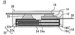
図1は、本発明の実施の形態1に係る半導体装置の断面図である。半導体装置10は、半導体素子12を有している。半導体素子12は上面にエミッタが形成され下面にコレクタが形成されたIGBTである。半導体素子12の上面には、はんだ14を介して第1電極16が電気的に接続されている。第1電極16はエミッタ電極として機能する。
図5は、本発明の実施の形態2に係る半導体装置の断面図である。実施の形態1との相違点を中心に説明する。本発明の実施の形態2に係る半導体装置は、第3内部電極60を有している。第3内部電極60は、複数の第3櫛歯部60aと複数の第3櫛歯部60aを連結する第3連結部60bとを有している。第3内部電極60は、はんだ62を介して第2電極20に電気的に接続されている。具体的には複数の第3櫛歯部60aの1つの櫛歯がはんだを介して第2電極20の上面に接続されている。なお、第3内部電極60は、半導体素子12の上面側に形成されている。
図6は、本発明の実施の形態3に係る半導体装置の断面図である。実施の形態1との相違点を中心に説明する。第1内部電極100と第2内部電極102は上下方向に対向している。具体的には、第1連結部100bは半導体素子12の下面と面接触している。また、複数の第1櫛歯部100aは第1連結部100bから下方に伸びている。第2連結部102bの上面は第1連結部100bに対向している。そして、複数の第2櫛歯部102aは第2連結部102bから上方に伸びている。
図7は、本発明の実施の形態4に係る半導体装置の断面図である。実施の形態3との相違点を中心に説明する。本発明の実施の形態4に係る半導体装置は、第3内部電極124を有している。第3内部電極124は、複数の第3櫛歯部124aと複数の第3櫛歯部を連結する第3連結部124bとを有している。第3内部電極124は、はんだ126を介して第2電極20の上面に電気的に接続されている。この第3内部電極124は、半導体素子12の上面側に形成されている。
Claims (12)
- 半導体素子と、
前記半導体素子の上面に電気的に接続された第1電極と、
複数の第1櫛歯部と前記複数の第1櫛歯部を連結する第1連結部とを有し、前記半導体素子の下面に面接触した第1内部電極と、
前記第1内部電極と電気的に接続された第2電極と、
前記複数の第1櫛歯部に接触せず前記複数の第1櫛歯部の間に進入する複数の第2櫛歯部と、前記複数の第2櫛歯部を連結する第2連結部とを有し、前記第1電極の下面に電気的に接続された第2内部電極と、
前記複数の第1櫛歯部と前記複数の第2櫛歯部の間を埋める下部誘電体と、を備えたことを特徴とする半導体装置。 - 前記半導体素子、前記第1内部電極、及び前記第2内部電極を覆い、前記第1電極の一部、前記第2電極の一部、及び前記下部誘電体の一部を外部に露出させる樹脂を備え、
前記複数の第1櫛歯部の1つの櫛歯が前記半導体素子の下面と面接触したことを特徴とする請求項1に記載の半導体装置。 - 複数の第3櫛歯部と、前記複数の第3櫛歯部を連結する第3連結部とを有し、前記第2電極に電気的に接続され、前記半導体素子の上面側に形成された第3内部電極と、
前記複数の第3櫛歯部に接触せず前記複数の第3櫛歯部の間に進入する複数の第4櫛歯部と、前記複数の第4櫛歯部を連結する第4連結部とを有し、前記第1電極の上面に電気的に接続された第4内部電極と、
前記複数の第3櫛歯部と前記複数の第4櫛歯部の間を埋める上部誘電体と、を備えたことを特徴とする請求項1に記載の半導体装置。 - 前記半導体素子、前記第1内部電極、前記第2内部電極、前記第3内部電極、及び前記第4内部電極を覆い、前記第1電極の一部、前記第2電極の一部、前記下部誘電体の一部、及び前記上部誘電体の一部を外部に露出させる樹脂を備えたことを特徴とする請求項3に記載の半導体装置。
- 前記半導体素子、及び前記第1内部電極を覆い、前記第1電極の一部、及び前記第2電極の一部を外部に露出させる樹脂を備え、
前記第1連結部は前記半導体素子の下面と面接触し、
前記複数の第1櫛歯部は前記第1連結部から下方に伸び、
前記第2連結部の上面は前記第1連結部に対向し、
前記樹脂は、前記第2連結部の下面を外部に露出させることを特徴とする請求項1に記載の半導体装置。 - 前記半導体素子、前記第1内部電極、及び前記第4内部電極を覆い、前記第1電極の一部、及び前記第2電極の一部を外部に露出させる樹脂を備え、
前記第1連結部は前記半導体素子の下面と面接触し、
前記複数の第1櫛歯部は前記第1連結部から下方に伸び、
前記第2連結部の上面は前記第1連結部に対向し
前記第4連結部の下面は前記第1電極の上面と対向しつつ電気的に接続され、
前記複数の第4櫛歯部は前記第4連結部から上方に伸び、
前記第3連結部の下面は前記第4連結部に対向し、
前記樹脂は前記第2連結部の下面、及び前記第3連結部の上面を外部に露出させることを特徴とする請求項3に記載の半導体装置。 - 前記下部誘電体は樹脂フィルム又はセラミックで形成されたことを特徴とする請求項1又は2に記載の半導体装置。
- 前記下部誘電体と前記上部誘電体は樹脂フィルム又はセラミックで形成されたことを特徴とする請求項3又は4に記載の半導体装置。
- 前記第1内部電極、前記下部誘電体、及び前記第2内部電極からなるコンデンサを整流コンデンサとして用いたことを特徴とする請求項1に記載の半導体装置。
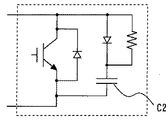
- 前記第1内部電極、前記下部誘電体、及び前記第2内部電極からなるコンデンサをスナバ回路のコンデンサとして用いたことを特徴とする請求項1に記載の半導体装置。
- 前記下部誘電体、前記第1内部電極、又は前記第2内部電極の前記樹脂と接する部分に凹部を有し、
前記凹部に前記樹脂が満たされたことを特徴とする請求項2に記載の半導体装置。 - 冷却体と、
前記冷却体の上に設けられた熱伝導材と、を備え、
前記下部誘電体の下面が前記熱伝導材に接触することを特徴とする請求項1に記載の半導体装置。
Priority Applications (4)
| Application Number | Priority Date | Filing Date | Title |
|---|---|---|---|
| JP2012053061A JP5754398B2 (ja) | 2012-03-09 | 2012-03-09 | 半導体装置 |
| DE102012224354.2A DE102012224354B4 (de) | 2012-03-09 | 2012-12-21 | Halbleitervorrichtung |
| US13/733,723 US8754462B2 (en) | 2012-03-09 | 2013-01-03 | Semiconductor device |
| CN201310074184.1A CN103311191B (zh) | 2012-03-09 | 2013-03-08 | 半导体装置 |
Applications Claiming Priority (1)
| Application Number | Priority Date | Filing Date | Title |
|---|---|---|---|
| JP2012053061A JP5754398B2 (ja) | 2012-03-09 | 2012-03-09 | 半導体装置 |
Publications (3)
| Publication Number | Publication Date |
|---|---|
| JP2013187464A JP2013187464A (ja) | 2013-09-19 |
| JP2013187464A5 JP2013187464A5 (ja) | 2014-10-09 |
| JP5754398B2 true JP5754398B2 (ja) | 2015-07-29 |
Family
ID=49029640
Family Applications (1)
| Application Number | Title | Priority Date | Filing Date |
|---|---|---|---|
| JP2012053061A Active JP5754398B2 (ja) | 2012-03-09 | 2012-03-09 | 半導体装置 |
Country Status (4)
| Country | Link |
|---|---|
| US (1) | US8754462B2 (ja) |
| JP (1) | JP5754398B2 (ja) |
| CN (1) | CN103311191B (ja) |
| DE (1) | DE102012224354B4 (ja) |
Families Citing this family (6)
| Publication number | Priority date | Publication date | Assignee | Title |
|---|---|---|---|---|
| WO2013140503A1 (ja) * | 2012-03-19 | 2013-09-26 | 三菱電機株式会社 | 半導体装置、半導体システム |
| WO2015133024A1 (ja) * | 2014-03-06 | 2015-09-11 | 三菱電機株式会社 | 電力用半導体装置 |
| WO2020218298A1 (ja) * | 2019-04-24 | 2020-10-29 | ローム株式会社 | 半導体装置 |
| US20220165719A1 (en) | 2019-04-24 | 2022-05-26 | Rohm Co., Ltd. | Semiconductor device |
| US11538748B2 (en) | 2020-06-04 | 2022-12-27 | Mediatek Singapore Pte. Ltd. | Semiconductor device with capacitor element |
| DE102022211040A1 (de) | 2022-10-19 | 2024-04-25 | Robert Bosch Gesellschaft mit beschränkter Haftung | Halbleitermodul |
Family Cites Families (23)
| Publication number | Priority date | Publication date | Assignee | Title |
|---|---|---|---|---|
| JPH05299584A (ja) | 1992-02-21 | 1993-11-12 | Toshiba Corp | 薄膜容量素子及び半導体記憶装置 |
| JPH06140446A (ja) | 1992-07-21 | 1994-05-20 | Hitachi Ltd | 半導体装置及びそれを用いた電子装置 |
| JP3340003B2 (ja) * | 1995-11-20 | 2002-10-28 | 京セラ株式会社 | 多層配線基板及び半導体素子収納用パッケージ |
| JPH10174424A (ja) | 1996-10-07 | 1998-06-26 | Toshiba Corp | 電力変換装置 |
| JP2000058372A (ja) | 1998-08-04 | 2000-02-25 | Toshiba Corp | セラミックコンデンサ実装構造 |
| JP2000092847A (ja) | 1998-09-14 | 2000-03-31 | Denso Corp | コンデンサ付き半導体モジュール装置 |
| JP3553849B2 (ja) | 2000-03-07 | 2004-08-11 | 富士電機デバイステクノロジー株式会社 | 半導体装置及びその製造方法 |
| JP4044265B2 (ja) | 2000-05-16 | 2008-02-06 | 三菱電機株式会社 | パワーモジュール |
| US6558169B2 (en) * | 2001-03-29 | 2003-05-06 | Intel Corporation | Shunt power connection for an integrated circuit package |
| JP4060657B2 (ja) * | 2002-07-18 | 2008-03-12 | Necトーキン株式会社 | 固体電解コンデンサとその製造方法 |
| JP2004350400A (ja) | 2003-05-22 | 2004-12-09 | Hitachi Ltd | 電力変換装置 |
| DE10345247B4 (de) | 2003-09-29 | 2007-10-04 | Infineon Technologies Ag | Verwendung von Leiterbahnen als Krallkörper |
| JP2005341643A (ja) * | 2004-05-24 | 2005-12-08 | Toshiba Corp | 電力変換器のブスバー装置 |
| JP2006174566A (ja) * | 2004-12-14 | 2006-06-29 | Toyota Motor Corp | 電流制御素子、昇圧装置およびインバータ装置 |
| JP2006222347A (ja) * | 2005-02-14 | 2006-08-24 | Toyota Motor Corp | 半導体モジュールと半導体モジュールの製造方法 |
| JP4661645B2 (ja) * | 2005-03-23 | 2011-03-30 | トヨタ自動車株式会社 | パワー半導体モジュール |
| KR100876247B1 (ko) * | 2006-10-19 | 2008-12-26 | 삼성에스디아이 주식회사 | 이차전지 및 그 제조방법 |
| JP5061717B2 (ja) | 2007-05-18 | 2012-10-31 | 富士電機株式会社 | 半導体モジュール及び半導体モジュールの製造方法 |
| JP5151338B2 (ja) * | 2007-09-14 | 2013-02-27 | 株式会社Ihi | コンデンサ内蔵絶縁型半導体パワーモジュール |
| US8053865B2 (en) * | 2008-03-10 | 2011-11-08 | Taiwan Semiconductor Manufacturing Company, Ltd. | MOM capacitors integrated with air-gaps |
| JP5169353B2 (ja) * | 2008-03-18 | 2013-03-27 | 三菱電機株式会社 | パワーモジュール |
| JP5332753B2 (ja) | 2009-03-10 | 2013-11-06 | 日産自動車株式会社 | 機電一体型駆動装置 |
| JP5469584B2 (ja) | 2010-10-28 | 2014-04-16 | 株式会社日立製作所 | バスバ間内蔵コンデンサ、電力機器及び電力変換装置 |
-
2012
- 2012-03-09 JP JP2012053061A patent/JP5754398B2/ja active Active
- 2012-12-21 DE DE102012224354.2A patent/DE102012224354B4/de active Active
-
2013
- 2013-01-03 US US13/733,723 patent/US8754462B2/en active Active
- 2013-03-08 CN CN201310074184.1A patent/CN103311191B/zh active Active
Also Published As
| Publication number | Publication date |
|---|---|
| US8754462B2 (en) | 2014-06-17 |
| US20130234291A1 (en) | 2013-09-12 |
| CN103311191B (zh) | 2016-08-10 |
| CN103311191A (zh) | 2013-09-18 |
| DE102012224354B4 (de) | 2021-09-30 |
| JP2013187464A (ja) | 2013-09-19 |
| DE102012224354A1 (de) | 2013-09-12 |
Similar Documents
| Publication | Publication Date | Title |
|---|---|---|
| JP6230660B2 (ja) | 電力用半導体モジュール | |
| US9871463B2 (en) | Power module | |
| JP5754398B2 (ja) | 半導体装置 | |
| JP6233507B2 (ja) | パワー半導体モジュールおよび複合モジュール | |
| JP4613077B2 (ja) | 半導体装置、電極用部材および電極用部材の製造方法 | |
| KR101581610B1 (ko) | 반도체 장치 및 그 제조 방법 | |
| EP3104412B1 (en) | Power semiconductor module | |
| JP5678884B2 (ja) | 電力変換装置 | |
| JP2007073743A (ja) | 半導体装置 | |
| US8373197B2 (en) | Circuit device | |
| WO2015072105A1 (ja) | パワーモジュール | |
| IT201800004209A1 (it) | Dispositivo semiconduttore di potenza con relativo incapsulamento e corrispondente procedimento di fabbricazione | |
| JP2009010252A (ja) | 半導体装置 | |
| KR101734712B1 (ko) | 파워모듈 | |
| JP6813259B2 (ja) | 半導体装置 | |
| JP7176397B2 (ja) | 半導体装置とその製造方法 | |
| JP5619232B2 (ja) | 半導体装置および電極用部材の製造方法 | |
| WO2021029150A1 (ja) | 半導体装置 | |
| JP5151338B2 (ja) | コンデンサ内蔵絶縁型半導体パワーモジュール | |
| JP7155748B2 (ja) | 半導体装置 | |
| JP5485833B2 (ja) | 半導体装置、電極用部材および電極用部材の製造方法 | |
| JP7118204B1 (ja) | 半導体装置 | |
| KR20190085587A (ko) | 고열전도성 반도체 패키지 | |
| WO2024024067A1 (ja) | 電力変換装置、電力変換装置の製造方法 | |
| JP2016214012A (ja) | 電力変換装置 |
Legal Events
| Date | Code | Title | Description |
|---|---|---|---|
| A521 | Request for written amendment filed |
Free format text: JAPANESE INTERMEDIATE CODE: A523 Effective date: 20140430 |
|
| A621 | Written request for application examination |
Free format text: JAPANESE INTERMEDIATE CODE: A621 Effective date: 20140430 |
|
| A521 | Request for written amendment filed |
Free format text: JAPANESE INTERMEDIATE CODE: A523 Effective date: 20140821 |
|
| A977 | Report on retrieval |
Free format text: JAPANESE INTERMEDIATE CODE: A971007 Effective date: 20141212 |
|
| A131 | Notification of reasons for refusal |
Free format text: JAPANESE INTERMEDIATE CODE: A131 Effective date: 20150106 |
|
| A521 | Request for written amendment filed |
Free format text: JAPANESE INTERMEDIATE CODE: A523 Effective date: 20150127 |
|
| TRDD | Decision of grant or rejection written | ||
| A01 | Written decision to grant a patent or to grant a registration (utility model) |
Free format text: JAPANESE INTERMEDIATE CODE: A01 Effective date: 20150428 |
|
| A61 | First payment of annual fees (during grant procedure) |
Free format text: JAPANESE INTERMEDIATE CODE: A61 Effective date: 20150511 |
|
| R150 | Certificate of patent or registration of utility model |
Ref document number: 5754398 Country of ref document: JP Free format text: JAPANESE INTERMEDIATE CODE: R150 |
|
| R250 | Receipt of annual fees |
Free format text: JAPANESE INTERMEDIATE CODE: R250 |
|
| R250 | Receipt of annual fees |
Free format text: JAPANESE INTERMEDIATE CODE: R250 |
|
| R250 | Receipt of annual fees |
Free format text: JAPANESE INTERMEDIATE CODE: R250 |
|
| R250 | Receipt of annual fees |
Free format text: JAPANESE INTERMEDIATE CODE: R250 |
|
| R250 | Receipt of annual fees |
Free format text: JAPANESE INTERMEDIATE CODE: R250 |
|
| R250 | Receipt of annual fees |
Free format text: JAPANESE INTERMEDIATE CODE: R250 |