JP5552589B2 - Bullet ball machine - Google Patents
Bullet ball machine Download PDFInfo
- Publication number
- JP5552589B2 JP5552589B2 JP2008284034A JP2008284034A JP5552589B2 JP 5552589 B2 JP5552589 B2 JP 5552589B2 JP 2008284034 A JP2008284034 A JP 2008284034A JP 2008284034 A JP2008284034 A JP 2008284034A JP 5552589 B2 JP5552589 B2 JP 5552589B2
- Authority
- JP
- Japan
- Prior art keywords
- notice
- hold
- display
- mode
- determination
- Prior art date
- Legal status (The legal status is an assumption and is not a legal conclusion. Google has not performed a legal analysis and makes no representation as to the accuracy of the status listed.)
- Active
Links
Images


Landscapes
- Display Devices Of Pinball Game Machines (AREA)
- Pinball Game Machines (AREA)
Description
本発明は、実行条件が成立した後、開始条件の成立に基づいて識別情報の可変表示を行い、遊技者に有利な特別遊技状態とするか否かを導出結果として表示する弾球遊技機に関するものである。 The present invention relates to a ball game machine that performs variable display of identification information based on establishment of a start condition after an execution condition is established, and displays as a derivation result whether or not a special gaming state is advantageous to the player. Is.
パチンコ遊技機のデジパチは、入球口(始動口)への遊技球の入球を起因として図柄の可変表示を行い、予め定められた表示結果となった場合に遊技者に有利な遊技状態(所謂大当り)となる構成である。またこれらのパチンコ遊技機は、短時間に複数の遊技球が始動口に入球した場合、保留記憶機能によって所定個数まで入球時に取得した情報を記憶し、記憶数に応じて保留記憶表示を行い、開始条件が成立するごとに取得した情報に基づいて可変表示を行い導出結果を表示するものが多い。 The digipachi of pachinko machines performs a variable display of symbols due to the entrance of the game ball to the entrance (starting entrance), and a gaming state advantageous to the player when a predetermined display result is obtained ( This is a so-called big hit. In addition, these pachinko machines store the information acquired at the time of entering a predetermined number of balls when a plurality of game balls enter the starting port in a short time, and display the stored memory display according to the stored number. In many cases, the derivation result is displayed by performing variable display based on the information obtained each time the start condition is satisfied.
この種のデジパチでは、始動口入球時から、可変表示を開始して導出結果が表示される直前までの期間に、大当りを期待させる予告演出を行う機能を備えるものが多い。また、予告演出として保留記憶表示の表示態様を用いる保留予告演出がある。この保留予告演出は、遊技球の始動口への入球を契機に、当該入球に係る保留記憶表示を通常とは異なる態様としたり、当該入球以前に記憶され未だ可変表示の開始条件が成立していない保留記憶表示も含め複数の保留記憶表示の態様を変化させる場合がある。 Many of these types of digipachis have a function of performing a notice effect for expecting a big hit during a period from the time of entering the start opening to the time immediately before starting the variable display and displaying the derived result. In addition, there is a hold notice effect that uses the display mode of the hold memory display as the notice effect. This hold notice effect is triggered by the entry of the game ball into the start opening, and the hold storage display related to the entry is different from the normal, or the variable display start condition stored before the entry is not yet changed. There may be a case where a plurality of hold memory display modes are changed including a hold memory display that is not established.
これらの保留予告演出の具体的な処理として、入球時に取得した情報を該情報の記憶処理時に判定し、その判定結果を基に保留予告演出を実施するものがある。記憶処理時に判定の対象となる情報は、大当りか否かに係る当否判定用乱数の場合が多く、この場合遊技者は保留予告演出の出現を大当りの期待度が高いと認識することになる。加えてこの保留予告演出は、可変表示中に出現する予告演出に比べ、出現から保留予告演出に係る導出結果が表示されるまでに長時間かかり、該保留予告演出以前に未だ可変表示の開始条件が成立していない保留記憶が表示されている場合は更に長時間となる。このように出現してから導出結果が表示されるまでに長時間かかるということがこの保留予告演出の特徴であり、遊技者は期待感の保持を長時間継続することが可能な予告演出といえる。
上記した、保留予告演出は、遊技者の大当りへの期待感が大きい故に、該保留予告演出が出現した時点で遊技者は遊技球の発射操作を該保留予告演出の結果が表示されるまで中断してしまうことが多々ある。これは稼動数の増加を絶えず念頭に置く遊技機設置施設においては好ましい状況ではない。 Since the above-described hold notice effect has a great expectation for the player's jackpot, when the hold notice effect appears, the player interrupts the launch operation of the game ball until the result of the hold notice effect is displayed. There are many things that end up. This is not a favorable situation in a game machine installation facility that constantly keeps in mind the increase in the number of operations.
またこの保留予告演出は、上述したように、出現してから保留予告演出を行った保留記憶が可変表示を経て導出結果を表示するまでの長時間に亘って期待感を継続することが可能な予告演出であり、期待感が大きい故に発射操作を中断した場合、長時間の稼動中断が余儀なくされる予告演出とも言える。加えて、保留予告演出が出現した時点で未だ可変表示に至っていない記憶表示が複数有る場合は、更に稼動中断期間が増加することとなる。 In addition, as described above, this hold notice effect can maintain a sense of expectation over a long period of time from the appearance of the hold notice effect to the display of the derivation result through the variable display. This is a notice effect, and it can be said that if the launch operation is interrupted because the expectation is great, the operation is interrupted for a long time. In addition, when there are a plurality of storage displays that have not yet reached the variable display at the time when the hold notice effect appears, the operation interruption period further increases.
本願発明はそれらの問題に鑑み、遊技球の始動口入球時の判定を基にする保留予告演出を実施しても、長時間の期待感はそのままに、遊技者が発射操作を中断することなく意欲的に継続し、稼動数の減少を抑止することが可能な弾球遊技機を提供することを目的とする。 In view of these problems, the present invention makes it possible for a player to interrupt a launch operation while maintaining a long-term expectation effect even if a hold notice effect based on the determination at the start of a game ball is entered. It aims to provide a ball game machine that can continue eagerly and suppress the decrease in the number of operations.
請求項1記載の弾球遊技機は、
始動口への遊技球の入球により大当り判定用乱数を取得して実行条件が成立した後、開始条件の成立に基づいて識別情報の可変表示を行い、前記大当り判定用乱数の判定結果に基づいて遊技者に有利な特別遊技を実行するか否かを前記識別情報にて示す遊技機であって、
遊技の進行を制御する主制御装置と、該主制御装置から送信されるコマンドを基に、識別情報の表示に関わる演出を制御する演出制御装置と、を備え、
前記主制御装置は、
前記実行条件が成立した時に前記開始条件が成立していない場合は、前記大当り判定用乱数を所定の上限個数まで保留記憶情報として記憶する保留記憶手段と、
前記実行条件が成立した時に記憶した保留記憶数を保留球数指示信号として前記演出制御装置に送信する保留記憶数送信手段と、
前記実行条件の成立時に、前記大当り判定用乱数に基づいて判定を行う実行条件成立時判定手段と、
該実行条件成立時判定手段の判定を基に予告の実行を許可する予告許可信号を前記演出制御装置に送信する予告許可手段と、を含み、
前記演出制御装置は、
前記主制御装置から受信した、前記保留球数指示信号を基に前記保留記憶数と同じ個数の保留記憶表示を行う保留表示制御手段と、
前記予告許可信号を受信した時に予告を行うか否かの判定を行う予告判定手段と、
該予告判定手段により予告を行うと判定した場合、該判定の基となった前記実行条件の成立を示す保留記憶表示の態様を保留予告態様として表示する保留予告態様表示手段と、
該保留予告態様の表示開始から該保留予告態様を示す保留記憶の開始条件成立による可変表示の終了までに前記保留球数指示信号を受信すると、
前記保留予告態様にて表示された前記保留記憶表示以降に保留記憶された保留記憶表示の態様を保留予告期待度態様として表示する保留予告期待度態様表示手段を含み、
該保留予告期待度態様表示手段は、前記保留予告態様にて表示された保留記憶にて前記特別遊技が実行されるかの期待度を文字の組合せにて報知するものであり、前記保留球数指示信号を受信する毎に段階的に該組合せを表示し、最終段階まで表示されることにより文字の組合せが完成する
ことを特徴とする弾球遊技機である。
The ball game machine according to
After the execution condition is established by acquiring the big hit determination random number by entering the game ball into the start port, the identification information is variably displayed based on the establishment of the start condition, and based on the determination result of the big hit determination random number A game machine indicating whether or not to execute a special game advantageous to the player by the identification information,
A main control device that controls the progress of the game, and an effect control device that controls an effect related to the display of the identification information based on a command transmitted from the main control device,
The main controller is
If the start condition is not satisfied when the execution condition is satisfied, the storage unit for storing the jackpot determination random number as the storage information to a predetermined upper limit number,
A reserved memory number transmitting means for transmitting the reserved memory number stored when the execution condition is satisfied to the effect control device as a reserved ball number instruction signal;
An execution condition satisfaction determination means for performing determination based on the jackpot determination random number when the execution condition is satisfied;
Notice permission means for transmitting a notice permission signal for permitting execution of the notice based on the determination of the execution condition establishment time decision means to the effect control device,
The production control device
On-hold display control means for performing the same number of on-hold storage display as the on-hold storage number based on the on-hold ball number instruction signal received from the main control device;
Notice determination means for determining whether to give a notice when the notice permission signal is received;
When it is determined that the advance notice is to be given by the advance notice determining means, a hold notice mode display means for displaying a hold storage display mode indicating the establishment of the execution condition that is the basis of the determination as a hold notice mode;
When the pending ball number instruction signal is received from the start of display of the pending notice mode to the end of variable display due to the establishment of the hold storage start condition indicating the pending notice mode,
Including a hold notice expectation degree display means for displaying a hold notice display form that has been stored on hold after the hold notice display displayed in the hold notice form as a hold notice expectation degree form;
The hold advance notice expectation state display means notifies the expectation degree of whether or not the special game is executed in the hold storage displayed in the hold advance notice form by a combination of characters. The ball game machine is characterized in that the combination is displayed step by step each time an instruction signal is received, and the character combination is completed by displaying the combination to the final step .
実行条件は、始動口へ遊技球が入球した時に成立する条件であり、入球によって遊技に係る各種情報を取得することによって成立してもよく、保留記憶処理で行われる乱数値等抽出処理が実行されたこととしてもよい。識別情報は遊技者が認識可能な情報として特別図柄としてもよく演出図柄でもよい。 The execution condition is a condition that is satisfied when a game ball enters the start port, and may be satisfied by acquiring various information related to the game by entering the ball, or a random number value extraction process performed in the hold storage process May be executed. The identification information may be a special symbol or an effect symbol as information that can be recognized by the player.
開始条件は、前回の特別図柄の可変表示が終了したときに成立する条件であればよく、特別図柄及び演出図柄が可変表示中でなく、保留記憶の記憶数が0でないこととしてもよい。 The start condition may be a condition that is satisfied when the previous variable symbol variable display is completed, and the special symbol and the effect symbol may not be variably displayed, and the number of reserved memories may not be zero.
実行条件成立時判定手段の判定対象となり得るのは、遊技球が始動口入球時に取得する全ての情報であり、大当りとなるか否かの当否結果、変動パターン又は変動時間(可変時間)、導出結果となる識別情報の種類等を決定する情報でもよく、複数の情報を用いて判定してもよい。更に、始動口入球時に予告演出を許可するか否かを判定するために用いる情報(乱数)を取得する構成とし判定対象としてもよい。 What can be determined by the determination means when the execution condition is satisfied is all information that the game ball acquires when entering the start opening, whether or not it is a big hit, variation pattern or variation time (variable time), Information that determines the type of identification information that is a derivation result may be used, or determination may be made using a plurality of pieces of information. Furthermore, it is good also as a determination object as the structure which acquires the information (random number) used in order to determine whether a notice effect is permitted at the time of starting-port entrance.
演出制御装置の予告判定手段は、主制御装置から予告許可信号を受信した際に何らかの判定基準を用いて予告を実行するか否かを判定するものであり、予告許可信号に含まれる情報を判断基準としてもよく、予告許可信号受信時に予告を実施するか否かを判定する乱数を取得する構成としても良い。また、予告を実行するか否かは主制御装置で判定し実行判定となった場合、演出制御装置に予告実行を支持する信号を送信する構成としてもよい。 The notice determining unit of the effect control apparatus determines whether or not to execute the notice using a certain criterion when the notice permission signal is received from the main control apparatus, and determines information included in the notice permission signal. A reference may be used, and a random number for determining whether or not to perform a notice when a notice permission signal is received may be obtained. Moreover, it is good also as a structure which transmits the signal which supports advance notice execution to a production | presentation control apparatus, when it determines with a main control apparatus whether execution of a notice is performed and it becomes execution determination.
保留記憶表示は、遊技者がその数と態様の変化が認識可能であれば表示に用いる部材を限定するものではなく、ランプ・LEDで行ってもよく、LCDを用いた演出図柄表示装置で行ってもよい。保留予告態様は、通常の保留記憶表示の態様と異なるものであれば良いが、一見して態様の差異が認識できるものが望ましい。従って、表示に用いる部材がランプ・LEDの場合、発光色や点滅速度の変化、又はその組合せによって通常時との差異や、保留予告表示態様の変化を表すものとしても良い。 As long as the player can recognize the change in the number and mode, the reserved memory display is not limited to the member used for the display, and may be performed with a lamp / LED, or with an effect symbol display device using an LCD. May be. The hold notice mode may be different from the normal hold storage display mode, but it is desirable that the mode difference can be recognized at a glance. Therefore, when the member used for the display is a lamp / LED, a change from the normal time or a change in the hold notice display mode may be represented by a change in emission color or blinking speed, or a combination thereof.
期待度を表す変化内容とは、数値や文言等の具体的な表現への変化によって期待度を示すだけでなく、暖寒色といった色彩の変化が伝える感覚や、三角形、四角形、☆形といった一般的な図形形状が与える感覚を用いて期待度を示すものでも良く、これらの一般的なイメージは、色の変化においては、温かみを感じさせる暖色系への変化は、期待度が高いことを表し、多角形への形状の変化では角の数が多いほど期待度が高いことを表すといえる。また、期待度を表す表現として、保留予告態様が期待度としてパーセンテージ表示や、レベルメータ表示等に変化し同時に演出用の可動物が期待度を表す作動を実施することまで含む。 The content of change that represents the degree of expectation is not only the degree of expectation due to changes to specific expressions such as numerical values and wordings, but also general senses such as triangles, quadrilaterals, and ☆ shapes that convey color changes such as warm and cold colors It is possible to show the degree of expectation using the sensation given by a simple figure shape, and these general images show that in the color change, the change to the warm color system that makes you feel warm, the degree of expectation is high, In the change of shape to a polygon, it can be said that the greater the number of corners, the higher the degree of expectation. In addition, as an expression representing the degree of expectation, the pending notice mode changes to a percentage display, a level meter display, or the like as the degree of expectation, and at the same time, an effect that the movable object for production represents the degree of expectation is included.
請求項1記載の弾球遊技機によれば、始動口入球時の判定結果を基にした保留記憶表示を用いた予告表示に対して、該予告表示中における始動口への入球が保留予告態様に影響を与えることになるため、大当り確率の高いと思われる保留記憶表示が行われていても、遊技者は発射操作を中止することなく継続し、稼動数の減少を抑止することが可能となる。また、期待度が段階的に明らかになっていく様子は、遊技者が所謂ステップアップ式の予告として捉えることが可能であり、従来の遊技機にはない興趣を付加している。
According to the ball game machine of
以下に本発明の好適な実施形態について図面を参照して説明する。尚、本発明の実施の形態は下記の実施例に何ら限定されるものではなく、本発明の技術的範囲に属する種々の形態を採り得ることができ、各実施例に記載された内容の相違部分を適宜組み合わせることが可能なことはいうまでもない。 Preferred embodiments of the present invention will be described below with reference to the drawings. The embodiments of the present invention are not limited to the following examples, and various forms belonging to the technical scope of the present invention can be adopted. Differences in contents described in the respective examples are possible. Needless to say, the portions can be appropriately combined.
図1は、本実施例のパチンコ機の遊技盤8の正面図である。なお、このパチンコ機の全体的な構成は公知技術に従っているので図示及び説明は省略する。
FIG. 1 is a front view of a
遊技盤8には公知のガイドレール25a、25bによって囲まれた略円形の遊技領域26が設けられ、多数の遊技釘27が植設されている。遊技領域26の略中央には、窓部28aを有する液晶枠飾り28が設けられており、演出図柄表示装置54b(図2参照)のLCD画面が遊技者から視認可能に構成され、図示しない公知のワープ入口、ワープ通路、ステージ等も設けられている。
The
また、窓部28aの上方左には、7セグメントLED等の発光部材により構成される特別図柄表示装置29、上方右には左と同一部材の普通図柄表示装置30が設けられており、窓部28a下には4個の発光部材で構成される特別図柄保留数表示装置29aが設けられている。特別図柄の保留記憶数は、LCD画面の保留記憶表示領域(図11参照)にも遊技者が視認可能に表示される。
Further, a special
液晶枠飾り28の左右両側又は左側には後述する普通図柄作動スイッチ42a(図2参照)を備える普通図柄作動ゲート42が設けられており、下側には始動口31と開放時のみ入賞可能となる普通電動役物40が始動口32として設けられている。普通電動役物40の下方には、アタッカー式の大入賞口33aを備える大入賞口ユニット33が配置され、該大入賞口ユニット33の下方にはアウト口34が設けられている。大入賞口33aの左側には4個のLEDで構成される普通図柄保留数表示装置41aが設けられている。
A normal
また、大入賞口ユニット33の左右両側には、後述する一般入賞口スイッチ35b(図2参照)を備える一般入賞口35aが複数備えられる入賞口ユニット35が設けられている。
In addition, on both the left and right sides of the big
上記のように遊技盤8を構成することによって、普通図柄作動ゲート42に入球(普通図柄作動スイッチ42a(図2参照)にて遊技球を検出)すると、普通図柄表示装置30で普通図柄が変動表示を開始し、所定時間後に停止した普通図柄の態様に応じて、後述する普通電役ソレノイド40b(図2参照)を駆動させる。普通電役ソレノイド40bを駆動させると、ほぼ同期して普通電動役物40の羽根部材が駆動して、普通電動役物40への入球(特別図柄始動スイッチ32a(図2参照)での検出率)が可能となるように構成されている。尚、本実施形態におけるパチンコ機では、普通電動役物40の羽根部材が駆動する開放時間は、通常時は0.3秒(1回)、時短状態(開放延長状態)では5.0秒(1回)である。
By configuring the
始動口31に遊技球が入球(第1特別図柄始動スイッチ31a(図2参照)にて遊技球を検出)すると、特別図柄表示装置29において特別図柄が変動を開始し、所定時間後に停止する。また、普通電動役物40に入球(特別図柄始動スイッチ32a(図2参照)にて遊技球を検出)すると、同様に特別図柄表示装置29において特別図柄が変動表示を開始し、所定時間後に停止する。また、特別図柄の変動中は、窓部28aに配置された演出図柄表示装置54bにおいて特別図柄の変動に連動した演出態様を表示する。
When a game ball enters the start port 31 (a game ball is detected by the first special
変動開始から所定時間後に停止した特別図柄の態様に応じて、後述する大入賞口ソレノイド33c(図2参照)を駆動させる。大入賞口ソレノイド33cを駆動させると、ほぼ同期して大入賞口ユニット33の扉部材が駆動して、大入賞口33aへの入球(カウントスイッチ33b(図2参照)での検出率)が可能となるように構成されている。
A special
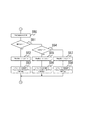
続いて、図2に本実施例におけるパチンコ機の電気配線を示すブロック図を示し説明する。図2には煩雑になる電源の供給系統に関する記載は行わないが、電源が必要な制御装置若しくはアクチュエータ類には、電源装置(図示せず)から直接的又は間接的に供給される構成となっている。尚、遊技盤8を装着するパチンコ機本体に関する部品は図示を省略している。
Subsequently, FIG. 2 will be described with reference to a block diagram showing electrical wiring of the pachinko machine in the present embodiment. FIG. 2 does not describe a complicated power supply system, but is configured to be supplied directly or indirectly from a power supply device (not shown) to a control device or actuator that requires power. ing. Note that the parts relating to the pachinko machine body on which the
図2に示す通り、主制御装置50の入力端には、遊技盤中継端子板62を介して始動口31に入球した遊技球を検出する特別図柄始動スイッチ31aと普通電動役物40に入球した遊技球を検出する特別図柄始動スイッチ32aと、普通図柄作動ゲート42に入球した遊技球を検出する普通図柄作動スイッチ42aと、大入賞口33aに入球した遊技球を検出するカウントスイッチ33bと、一般入賞口35aに入球した遊技球を検出する一般入賞口スイッチ35bとが接続されており、裏配線中継端子板63を介して前面枠が閉鎖していることを検出する前面枠閉鎖スイッチ38と、意匠枠が閉鎖していることを検出する意匠枠閉鎖スイッチ39a、39bと、が接続されている。
As shown in FIG. 2, at the input end of the
主制御装置50の出力端には、遊技盤中継端子板62を介して大入賞口33aの扉部材を駆動する大入賞口ソレノイド33cと、普通電動役物40の羽根部材を駆動する普通電役ソレノイド40bとが接続されており、図柄表示装置中継端子板64を介し特別図柄を表示する特別図柄表示装置29と、特別図柄の保留数を表示する特別図柄保留数表示装置29aと、普通図柄を表示する普通図柄表示装置30と、普通図柄の保留数を表示する普図保留数表示装置30aとが接続されており、裏配線中継端子板63及び外部接続端子板61を介して図示しないホールコンピュータ70と、が接続されている。
At the output end of the
主制御装置50はCPU、ROM、RAM等の電気部品を備えており、搭載するROMに記憶されたプログラムに従ってCPUにて処理を実行し、入力される各種検出信号などに基づいて遊技の進行に関わる各種コマンド等を生成し、払出制御装置51及びサブ統合装置53に出力する。ここで、主制御装置50と払出制御装置51とは双方向通信回路として構成され、主制御装置50とサブ統合制御装置53とは間に演出中継端子板65を介した主制御装置50からサブ統合制御装置53への一方向通信回路として構成されている。
The
払出制御装置51の入力端には、裏配線中継端子板63を介して球タンク(図示せず)又はタンクレール(図示せず)内の遊技球が不足していることを検出する球切れスイッチ22a又は23aと、裏配線中継端子板63及び払出中継端子板66を介して払い出した遊技球を検出する払出スイッチ24bと、各種端子板を介することなく下皿への経路に遊技球が多数あることを検出する満杯スイッチ13aと、が接続されている。払出制御装置51の出力端には、裏配線中継端子板63及び払出中継端子板66を介して遊技球を上皿へと払い出す払出モータ24aが接続されている。
At the input end of the
払出制御装置51はCPU、ROM、RAM等の電気部品を備えており、搭載するROMに記憶されたプログラムに従ってCPUにて処理を実行し、入力される各種検出信号ならびに主制御装置50から入力されるコマンドに基づいて遊技球の払い出しに関わる各種コマンド等を生成し、主制御装置50及び発射制御装置52に出力する。ここで、払出制御装置51と主制御装置50とは双方向通信回路として構成され、払出制御装置51と発射制御装置52とは払出制御装置51から発射制御装置52への一方向通信回路として構成されている。
The
また、払出制御装置51は、外部接続端子板61を介して賞球に関する情報などをホールコンピュータ70に送信するほか、発射制御装置52に対して発射停止信号を送信する。発射制御装置52は発射モータ36を制御して、遊技球を遊技領域26に遊技球を発射させる。なお、発射制御装置52には払出制御装置51以外に発射ハンドル18からの回動量信号、タッチスイッチ20aからのタッチ信号、発射停止スイッチ19aから発射停止スイッチ信号が入力される。回動量信号は、遊技者が発射ハンドル18を操作することで出力され、タッチ信号は遊技者が発射ハンドル18を触ることで出力され、発射停止スイッチ信号は、遊技者が発射停止スイッチ19aを押すことで出力される。なお、タッチ信号が発射制御装置52に入力されていなければ、遊技球は発射できないほか、発射停止スイッチ信号が入力されているときには、遊技者が発射ハンドル18を触っていても遊技球は発射出来ないようになっている。
In addition, the
サブ統合制御装置53の入力端には、遊技者により操作可能な遊技スイッチ14aが接続されている。サブ統合制御装置53の出力端には、図示しない意匠枠及び遊技盤8に備えられる各種LED・ランプ37と、前面枠及びスピーカユニットに備えられるスピーカ10と、が接続されている。尚、サブ統合制御装置53と主制御装置50とは間に演出中継端子板65を介した主制御装置50からサブ統合制御装置53への一方向通信回路として構成され、サブ統合制御装置53と演出図柄制御装置54aとはサブ統合制御装置53から演出図柄制御装置54aへの一方向通信回路として構成されている。
A
サブ統合制御装置53はCPU、ROM、RAM等の電気部品を備えており、搭載するROMに記憶されたプログラムに従ってCPUにて処理を実行し、入力される遊技スイッチ14aの入力ならびに主制御装置50から入力されるコマンドに基づいて演出に関わる各種コマンド等を生成し、演出図柄ユニット54の演出図柄制御装置54aに出力する。
The
また、サブ統合制御装置53には、音量を調節する音量調節スイッチ10aが備えられ、音量調節スイッチ10aの状態(位置)を検出し、その検出結果とスピーカ10へ送信する内容とを判断し、スピーカ10から出力する音量をソフト的に制御するように構成されている。
The sub integrated
演出図柄制御装置54aは、サブ統合制御装置53から受信したデータ及びコマンド(共に主制御装置50から送信されてきたものとサブ統合制御装置53が生成したものとがある)に基づいて演出図柄表示装置54bを制御して、演出図柄等の演出画像を窓部28aに表示させる。
The effect
本実施形態におけるパチンコ機は確率変動機として構成されている。具体的に説明すると、本実施形態のパチンコ機による遊技は、大入賞口33aを閉鎖した遊技と大入賞口33aを開放する大当たり遊技とに大別され、大入賞口33aを閉鎖した遊技には、大きく分類して、通常確率状態(以下、通常状態)と、該通常状態に比べて遊技者にとって有利な状態となる高確率状態(以下、確率変動状態)とが存在する。また通常状態は、特別図柄及び普通図柄の変動時間を短縮する時短状態を含む。
The pachinko machine in the present embodiment is configured as a probability variable machine. More specifically, games by the pachinko machine of the present embodiment are roughly divided into games that close the
特別図柄は、確率変動図柄及び非確率変動図柄とからなり、確率変動状態は確率変動図柄での大当たり遊技終了後に移行可能に設定され、通常状態、確率変動状態のうち、いずれの遊技状態でも確率変動図柄で大当たりすれば、該大当たり遊技終了後、確率変動状態に移行する。同様に通常状態は、非確率変動図柄での大当たり遊技終了後に移行可能に設定され、通常状態、確率変動状態のうち、いずれの遊技状態でも非確率変動図柄で大当たりすれば、該大当たり遊技終了後、通常状態に移行する。 The special symbol consists of a probability variation symbol and a non-probability variation symbol, and the probability variation state is set so as to be able to transition after the jackpot game in the probability variation symbol, and the probability in any game state of the normal state and the probability variation state If it is a big hit with a change symbol, after the jackpot game is over, it shifts to a probability fluctuation state. Similarly, the normal state is set so that it can be transferred after the jackpot game with the non-stochastic variation symbol is finished, and if either of the normal state or the probability variation state is a big hit with the non-probability variation symbol, after the jackpot game ends , Transition to normal state.
通常状態に移行後は、規定回数(例えば、100回)だけ特別図柄及び普通図柄の変動時間が短縮され、かつ普通電動役物40の開放延長機能が作動する時短状態となる。特別図柄及び普通図柄の変動時間(変動開始から結果が表示されるまでの時間)が短縮されると、一定時間内の変動表示回数が増大する。
After shifting to the normal state, the variation time of the special symbol and the normal symbol is shortened by a specified number of times (for example, 100 times), and the open extension function of the normal
具体的には、本実施形態の時短状態では、特別図柄の変動時間の短縮とともに、普通図柄表示装置30に表示される普通図柄の時間短縮も行われるが、この普通図柄の変動表示を短縮させることで、一定時間内で多数回普通図柄の確定表示を行う。従って、一定時間内での普通図柄が当りとなる回数が増大し、これにより普通電動役物40の作動回数も増大する。また、普通電動役物40の開放時間が長くなるように設定されているので、多数の遊技球が入賞し易くなる。このように多数の遊技球が入賞し易くなることにより、特別図柄の変動表示回数が更に増大されるとともに、普通電動役物40入賞による賞球により遊技者の持ち玉が減り難くなり、有利な遊技を行うことができる。
Specifically, in the time-saving state of the present embodiment, the special symbol is displayed in the normal
なお、確率変動状態では、時短状態と同様に、特別図柄及び普通図柄の変動時間が短縮され、普通電動役物40開放延長機能が作動する。各種図柄の短縮と普通電動役物40の開放延長機能に関わる設定は時短状態と同一であるが、確率変動状態は時短状態に加えて特別図柄の大当り確率が高くなる(大当りし易い)。
In the probability variation state, the variation time of the special symbol and the normal symbol is shortened and the normal
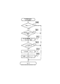
次に、主制御装置50が行う保留記憶処理について図3を用いて説明する。保留記憶処理は、本願発明における保留記憶手段と保留記憶数送信手段と実行条件成立時判定手段と予告許可手段とを含む処理となる。尚、メインルーチンとして行われる各処理は従来技術にそったものであるため、説明は割愛する。
Next, the hold storage process performed by the
保留記憶処理が開始されると、始動口31または普通電動役物40に遊技球が入球(特別図柄始動スイッチ31a又は特別図柄始動スイッチ32aが遊技球を検知)したか否か判定する(S10)。肯定判定であれば(S10:YES)、主制御装置50に既に格納されている保留記憶数が最大値(本願発明では4個)未満であるか否か判定する(S11)。肯定判定であれば(S11:YES)、当否乱数等の各種乱数を抽出し保留記憶として主制御装置50の保留記憶数に応じた記憶領域に記憶する (S12)。この構成が保留記憶手段となる。
When the on-hold storage process is started, it is determined whether or not a game ball enters the
続いて、確率変動フラグが0であるか否か判定する(S13)。確率変動フラグとは、主制御装置50にて記憶される値であり、確率変動フラグが0のときは、大当り確率が通常状態であることを、確率変動フラグが1のときは、確率変動状態であることを主制御装置50が判断するための値である。本願発明では、始動口31、普通電動役物40及び普通図柄作動ゲート42への遊技球入球時に、取得した各種乱数を判定するのは大当り確率が通常状態時のみであるが、確率変動状態時に同様の処理を行う構成でも何ら問題ない。
Subsequently, it is determined whether or not the probability variation flag is 0 (S13). The probability variation flag is a value stored in the
S13が肯定判定(大当り確率が通常状態)であれば(S13:YES)、最も新しく記憶された保留記憶を読み出し、大当り判定用乱数が通常確率時の大当り判定用テーブル1と異なるか否か判定する(S14)。肯定判定(大当り値とは異なる)であれば(S14:YES)、リーチ決定用乱数が通常時にスーパーリーチとなる値か否か判定する(S15)。S15が肯定判定(スーパーリーチとなる)か(S15:YES)、又はS14が否定判定(大当り判定用乱数が大当り値と一致)であれば(S14:NO)、予告許可信号をサブ統合装置53に送信する(S16)。尚、予告許可信号の内容は、大当り判定に基づく許可なのか、スーパーリーチ判定に基づく許可なのかが判断できる構成となっている。上記構成が、本願発明における実行条件成立時判定手段と、該実行条件成立時判定手段に基づく予告許可手段となる。本実施例では、始動口入球時に取得した各種乱数の中で、大当りとスーパーリーチに係る乱数(大当り判定用とリーチ決定用)の判定を基に保留記憶処理時に予告許可信号を送信する構成としたが、同じタイミングで他の乱数(例えば確率変動乱数や大当り図柄決定用乱数や変動パターン選択用乱数)の判定、または他の複数の乱数の判定の組合せを基に送信する構成でもよい。
If S13 is affirmative (the jackpot probability is in a normal state) (S13: YES), the most recently stored pending storage is read, and it is determined whether the jackpot determination random number is different from the jackpot determination table 1 at the normal probability. (S14). If the determination is affirmative (different from the big hit value) (S14: YES), it is determined whether or not the reach determination random number is a value that is super-reach at normal times (S15). If S15 is an affirmative determination (becomes super reach) (S15: YES), or if S14 is a negative determination (the jackpot determination random number matches the jackpot value) (S14: NO), a notice permission signal is sent to the
続いて、S16の処理の後か、S13の否定判定(確率変動状態)(S13:NO)の後か、S15の否定判定(非スーパーリーチ)(S15:NO)の後、S12で記憶処理した数を含む保留記憶数を示す保留記憶数指示信号をサブ統合装置53に送信する(S17)。この構成が本願発明における保留記憶数送信手段となる。 Subsequently, after the processing of S16, after the negative determination (probability variation state) of S13 (S13: NO), or after the negative determination (non-super reach) of S15 (S15: NO), the storage processing is performed in S12. A reserved memory number instruction signal indicating the number of reserved memories including the number is transmitted to the sub-integrating device 53 (S17). This configuration is the reserved memory number transmission means in the present invention.
尚、上記S12で抽出し記憶する乱数の種類には、大当り判定用乱数、確率変動乱数、リーチ決定用乱数、変動パターン選択用乱数及び大当り図柄決定用乱数等があり、各乱数とそれぞれの判定に用いるテーブル構成は従来技術にそったものである。また、始動口入球時に予告を許可するか否かを判定する専用の乱数を取得し記憶する構成としてもよく、それに合わせ予告許可テーブルを備える構成としてもよい。 Note that the types of random numbers extracted and stored in S12 include jackpot determination random numbers, probability variation random numbers, reach determination random numbers, variation pattern selection random numbers, jackpot symbol determination random numbers, and the like. The table configuration used in the above is in accordance with the prior art. Further, it may be configured to acquire and store a dedicated random number for determining whether or not to allow the advance notice when entering the starting opening, and may be provided with a notice allowance table accordingly.
上記処理では、予告許可信号を送信するのは、保留記憶処理時に特別図柄が大当り判定の場合か、若しくは非大当りでスーパーリーチ決定となる判定の場合となる。このような判定基準構成(特にスーパーリーチになるか否かを考慮した点)にした効果を以下に述べる。 In the above process, the notice permission signal is transmitted when the special symbol is a big hit determination at the time of the hold storage process or when the super reach determination is determined by a non-big hit. The effect of such a determination criterion configuration (particularly in consideration of whether or not to become super reach) will be described below.
保留記憶表示を用いた予告の演出効果を考えた場合、始動口31又は普通電動役物40への入球状況即ち保留記憶数の有無にも左右されるが、予告が遊技者に報知されてからその結果が導出されるまでに長い時間を費やす場合が多く、遊技者の期待感もその時間に合わせて長くなることが特徴といえる。しかしながらこれは、期待する時間が長ければ長いほどその結果によっては落胆の度合いも他の予告に比べ大きくなる予告演出ともいえる。
When considering the effect of the advance notice using the hold memory display, the advance notice is notified to the player, although it depends on the state of entering the starting
本願発明ではその解決手段として保留予告演出の結果がハズレの場合、特別図柄の変動の変動パターンはスーパーリーチとなるよう構成した。この構成により、保留予告演出の結果が外れる(大当りしない)ものであっても、最終結果が表示されるまでスーパーリーチの変動態様が遊技者の期待感を大きく振幅させ演出効果を最後まで発揮するとともに、「大当りに近づいた」、「もう少しで大当りだった」という感覚を遊技者に与え再遊技意向を高める構成としている。 In the present invention, as a means for solving the problem, when the result of the holding notice effect is lost, the variation pattern of the special symbol variation is configured to be super reach. With this configuration, even if the result of the hold notice effect is off (not a big hit), the variation mode of super reach greatly amplifies the player's expectation until the final result is displayed, and the effect of the effect is exhibited to the end. At the same time, it is configured to give the player a sense of “coming close to the big hit” or “it was a little more big hit” to increase the player's intention to replay.
図3に示す処理の説明に戻り、S17の処理が終わるか、S10で否定判定(S10:NO)か又はS11で否定判定(S11:NO)の場合、リターンとなる。 Returning to the description of the processing shown in FIG. 3, if the processing of S17 is completed, or if a negative determination is made in S10 (S10: NO) or a negative determination is made in S11 (S11: NO), a return is returned.
次に、サブ統合装置53が実行する保留球数・予告判定処理について説明する。保留球数・予告判定処理は、本願発明における保留表示制御手段と予告判定手段と保留予告態様表示手段と保留予告態様変化手段とを含む処理となる。従ってこの処理が、演出図柄表示装置54bに表示する保留記憶表示の態様を、通常の保留記憶表示態様から保留予告態様へ、更に保留予告態様をその後の始動口への入球(主制御装置50から保留球数指示信号の受信)を起因として変化させることになる。
Next, the number of held balls / notice determination executed by the
図4に示す保留球数・予告判定処理では、主制御装置50から保留球数指示信号を受信したか否か判定する(S20)。肯定判定であれば(S20:YES)、保留球数カウンタの値に1を加え(S21)、主制御装置50から予告許可信号を受信したか否かを判定する(S22)。S22が肯定判定であれば(S22:YES)、予告フラグの値が0か否か判定する(S23)。保留球数カウンタは、新たな変動が開始(主制御装置50から変動指示コマンドを受信)される毎にデクリメントされる従来技術に沿ったカウンタである。 In the retained ball number / notice determination process shown in FIG. 4, it is determined whether or not a retained ball number instruction signal is received from the main controller 50 (S20). If the determination is affirmative (S20: YES), 1 is added to the value of the reserved ball number counter (S21), and it is determined whether a notice permission signal has been received from the main controller 50 (S22). If S22 is affirmative (S22: YES), it is determined whether or not the value of the notice flag is 0 (S23). The reserved ball number counter is a counter according to the prior art that is decremented each time a new change is started (a change instruction command is received from the main controller 50).
予告フラグは、サブ統合装置53で記憶される値であり、図9の(2)予告フラグの値と種類の表が示すように、予告フラグの値が0の時は保留予告が未実施であることを、予告フラグの値が1の時は、保留予告が実施中であり該保留予告は主制御装置50からの大当り判定に基づく予告許可信号受信により実施したことを、保留予告フラグの値が2の時は、保留予告が実施中であり該保留予告は主制御装置50からのスーパーリーチ判定に基づく予告許可信号の受信により実施したことをサブ統合装置53が判断するための値である。尚、予告フラグの値は、保留予告態様の保留記憶表示位置を把握するための予告態様保留球数カウンタ処理によって、該予告態様保留球数カウンタの値が0と判定された時点(保留予告に係る変動が開始した時点即ち保留予告態様の表示を終了した時点)で0がセットされる。
The notice flag is a value stored in the
S23が肯定判定(予告未実施)であれば(S23:YES)、予告判定用乱数の抽出処理を行う(S24)。次にS23で受信した予告許可信号が大当り判定に基づくものか否かを判定し(S25)、肯定判定ならば(S25:YES)、S24で抽出した乱数が、予告判定テーブル1の予告実施値となる値か否かを判定し(S26)、肯定判定ならば(S26:YES)、予告フラグの値に1をセットする(S27)。S25が否定判定の場合(S25:NO、スーパーリーチ判定に基づく予告許可信号を受信した場合)、S24で抽出した乱数が、予告判定テーブル2の予告実施値となる値か否かを判定し(S28)、肯定判定ならば(S28:YES)、予告フラグの値に2をセットする(S29)。 If S23 is affirmative (not notified) (S23: YES), a random number for predicting determination is extracted (S24). Next, it is determined whether or not the notice permission signal received in S23 is based on the jackpot determination (S25). If the determination is affirmative (S25: YES), the random number extracted in S24 is the notice execution value of the notice determination table 1. (S26: YES), the value of the notice flag is set to 1 (S27). When S25 is negative (S25: NO, when a notice permission signal based on super reach determination is received), it is determined whether or not the random number extracted in S24 is a value that is a notice execution value of the notice determination table 2 ( If the determination is affirmative (S28: YES), 2 is set to the value of the notice flag (S29).
図9(1)は予告判定用テーブルを説明するための図である。予告判定用テーブルは、主制御装置50から受信する予告許可信号が大当り判定に基づく場合と、スーパーリーチ判定に基づく場合のそれぞれに対応して設定されている。例えば、主制御装置50から受信した予告許可信号が、大当り判定に基づいて送信されたものであった場合、予告判定用に抽出した乱数は予告判定用テーブル1を用いて判定を行い、その値が「0〜6」ならば予告フラグの値は0のままとし保留予告は行わず、抽出した乱数の値が「7〜9」ならば予告フラグの値に1をセットし保留予告を実施する。
FIG. 9A is a diagram for explaining the notice determination table. The notice determination table is set corresponding to each of the case where the notice permission signal received from the
主制御装置50から受信した予告許可信号が、スーパーリーチ判定に基づいて送信されたものであった場合、予告判定用に抽出した乱数は予告判定用テーブル2を用いて判定を行い、その値が「0〜8」ならば予告フラグの値は0のままとし保留予告は行わず、抽出した乱数の値が「9」ならば予告フラグの値に2をセットし保留予告を実施する。
When the notice permission signal received from the
この設定により、主制御装置50から大当り判定に基づく予告許可信号とスーパーリーチ判定に基づく予告許可信号を受信した場合では保留予告を実施する確率が異り、大当り判定を基にした許可信号を受信した場合の保留予告実施を実施する確率が高くなる。これは、大当り判定及びスーパーリーチ判定となる確率によっても異なるが、保留予告が出現した場合は大当りとなる確率が高く、保留予告出現時の遊技者の期待感を裏切らない構成といえる。尚、各テーブルの設定についてはこの内容に限るものではない。
With this setting, when the notice permission signal based on the jackpot determination and the notice permission signal based on the super reach determination are received from the
図4の処理の説明に戻り、S27又はS29の処理に続き、予告態様保留球数カウンタをセットする(S30)。予告態様保留球数カウンタは、通常の保留記憶表示の表示位置を特定するための保留球数カウンタとは別に、保留予告態様の表示位置を特定するためのカウンタである。当該予告態様保留球数カウンタは、S21で+1した保留球数カウンタの値を初期値としてセットする。従って予告フラグに0以外の値がセットされるのとほぼ同時に予告態様保留球数カウンタがセットされる。 Returning to the explanation of the processing of FIG. 4, following the processing of S27 or S29, a notice mode reserved ball number counter is set (S30). The notice mode reserved ball number counter is a counter for specifying the display position of the hold notice mode separately from the reserved ball number counter for specifying the display position of the normal reserved memory display. The notice mode reserved ball number counter sets the value of the held ball number counter incremented by S21 as an initial value. Accordingly, the notice mode reserved ball number counter is set almost simultaneously with the setting of a value other than 0 to the notice flag.
上記した予告態様保留球数カウンタ処理について図10を用いて説明する。予告態様保留球数カウンタ処理を開始すると予告フラグの値が0とは異なるか否か判定する(S80)。肯定判定(S80:YES、予告実施中)ならば、主制御装置50から特別図柄変動指示コマンドを受信したか否かを判定し(S81)、肯定判定ならば(S81:YES)、予告態様保留球数カウンタの値から−1するデクリメント処理を行い(S82)、続いてデクリメント処理後の予告態様保留球数カウンタの値が0か否かを判定する(S83)。S83で予告態様保留球数カウンタの値が0と判定された時点で保留予告態様を表示した記憶保留が変動を開始したことになる。S83が肯定判定なら(S83:YES)、予告フラグの値に0をセットし(S84)、続いて後述する予告態様フラグの値に0をセットする(S85)。S85の処理後、又はS80の否定判定後(S80:NO)、又はS81の否定判定後(S81:NO)、又はS83の否定判定後(S83:NO)にリターンとなる。 The above-described notice mode reserved ball number counter process will be described with reference to FIG. When the notice mode reserved ball number counter process is started, it is determined whether or not the value of the notice flag is different from 0 (S80). If an affirmative determination is made (S80: YES, during advance notice), it is determined whether a special symbol variation instruction command has been received from the main controller 50 (S81). The decrement process is decremented by -1 from the value of the ball counter (S82), and then it is determined whether or not the value of the notice mode reserve ball counter after the decrement process is 0 (S83). When the value of the notice mode reserved ball number counter is determined to be 0 in S83, the storage hold displaying the hold notice mode has started to change. If S83 is affirmative (S83: YES), 0 is set to the value of the notice flag (S84), and then 0 is set to the value of the notice mode flag described later (S85). Return is made after the processing of S85, after the negative determination of S80 (S80: NO), after the negative determination of S81 (S81: NO), or after the negative determination of S83 (S83: NO).
図4の処理の説明に戻り、S30の処理の後、S21で保留球数カウンタに1を加えた値に該当する表示位置に保留予告態様の表示を指定する信号を演出図柄制御装置54aに送信する(S31)。S22が否定判定(S22:NO)、又はS26が否定判定(S26:NO)、又はS28が否定判定(S28:NO)なら、S21で保留球数カウンタに1を加えた値に該当する表示位置に通常の保留記憶態様を表示指定する信号を演出図柄制御装置54aに送信する(S32)。S31、S32の処理後又はS20が否定判定(S20:NO)ならば、リターンとなる。
Returning to the description of the processing of FIG. 4, after the processing of S30, a signal designating the display of the holding notice mode at the display position corresponding to the value obtained by adding 1 to the holding ball number counter in S21 is transmitted to the effect
図4の処理中において、S32に係る処理の流れが本願発明における保留表示制御手段となり、S24〜S26とS28が予告判定手段となり、S31が保留予告態様表示手段となり、S30と図10に示す処理がカウンタ手段となる。 In the process of FIG. 4, the flow of the process related to S32 becomes the hold display control means in the present invention, S24 to S26 and S28 become the notice determination means, S31 becomes the hold notice mode display means, and the processes shown in S30 and FIG. Is the counter means.
次に図4のS23否定判定(S23:NO)に続く図5の処理を説明する。これ以降の保留球数・予告判定処理に係る処理は、予告フラグの値が0以外の場合に行われる処理、即ち保留予告態様の表示中に保留球数指示信号を主制御装置50から受信(始動口31又は普通電動役物40への新たな入球に起因して)した場合の処理であり、本願発明における保留予告態様変化手段となる。
Next, the process of FIG. 5 following S23 negative determination (S23: NO) of FIG. 4 will be described. Subsequent processing related to the number of held balls / notice determining process is a process performed when the value of the notice flag is other than 0, that is, a hold ball number instruction signal is received from the
図5に示す処理は、前述した予告態様保留球数カウンタの値によって、保留予告態様を示す保留記憶表示がどの位置に表示されているかを判断し(保留記憶表示の表示位置の名称については図11を参照)、且つ通常の保留球数カウンタの値との差を参照することによって、保留予告態様の表示位置から何個目の保留球数指示信号を受信(新たな始動口31(又は普通電動役物40)への入球)したかを判定する処理となる。尚、保留予告態様を図11に示す保留記憶表示4の位置に表示中は、保留記憶数が最大値となるため、サブ統合装置53は主制御装置50から保留記憶数指示信号は受信することが無く、サブ統合装置53が新たな保留記憶数指示信号を受信するのは保留予告態様の表示が保留記憶表示3の位置にシフトしてからとなり、このときの予告態様保留球数カウンタの値は3となる。
In the process shown in FIG. 5, the position of the reserved storage display indicating the reserved advance notice mode is determined based on the value of the above-mentioned notice mode reserved ball number counter (for the names of the display positions of the reserved storage display, refer to FIG. 5). 11), and by referring to the difference from the value of the normal reserved ball number counter, the number of held balls number instruction signal is received from the display position of the hold notice mode (new start port 31 (or normal This is a process for determining whether or not a ball has entered the electric accessory 40). Note that while the hold notice mode is displayed at the position of the
図4のS23が否定判定(S23:NO)なら、予告態様保留球数カウンタの値が3か否か判定する(S40)。肯定判定なら(S40:YES)、図6の処理に進む。この判定内容は、保留予告態様の表示位置が保留記憶されてから時間が最も経過しているものから数えて3番目の位置(保留記憶表示3、図11参照)か否かを判定するものである。尚且つこの3番目の位置に保留予告態様を表示中の場合は、本願弾球遊技機の保留記憶数の最大値が4であるため、主制御装置50から保留球数指示信号を受信した場合は、保留球数カウンタに1が加算された結果としては、必ず4番目の位置(保留記憶表示4)への保留記憶の表示を指定することなる。
If S23 of FIG. 4 is negative determination (S23: NO), it will be determined whether the value of a notice style reservation ball number counter is 3 (S40). If it is affirmation determination (S40: YES), it will progress to the process of FIG. This determination content is to determine whether or not the display position of the hold notice mode is the third position (hold
S40が否定判定ならば(S40:NO)、予告態様保留球数カウンタの値が2か否か判定する(S41)。S41が否定判定なら(S41:NO)、通常の保留球数カウンタの値と予告態様保留球数カウンタの値の差が3か否か判定する(S42)。S42が否定判定(S42:NO)、又はS41が肯定判定なら(S41:YES)、通常の保留球数カウンタの値と予告態様保留球数カウンタの値の差が2か否か判定する(S43)。肯定判定なら(S43:YES)、図7の処理に進み、否定判定なら(S43:NO)、S40の肯定判定と同様に図6の処理に進む。S42が肯定判定なら(S42:YES)、図8の処理に進む。 If S40 is negative (S40: NO), it is determined whether or not the value of the notice mode reserved ball number counter is 2 (S41). If S41 is negative (S41: NO), it is determined whether or not the difference between the value of the normal reserved ball number counter and the value of the notice mode reserved ball number counter is 3 (S42). If S42 is negative (S42: NO) or S41 is positive (S41: YES), it is determined whether or not the difference between the value of the normal reserved ball number counter and the value of the notice mode reserved ball number counter is 2 (S43). ). If the determination is affirmative (S43: YES), the process proceeds to the process of FIG. 7, and if the determination is negative (S43: NO), the process proceeds to the process of FIG. If S42 is affirmative (S42: YES), the process proceeds to FIG.
S41とS43の判定では、保留予告態様の表示位置が保留記憶されてから最も時間が経過しているものから数えて2番目の位置(保留記憶表示2の位置)か否かを判定し(S41)、肯定判定であれば受信した保留球数指示信号分を加算した保留球数カウンタの値を参照(減算)し(S43)、保留予告態様の表示位置と新たに受信した保留球数指示信号の相対的な位置関係を判定する処理となる。 In the determinations in S41 and S43, it is determined whether or not the display position of the hold notice mode is the second position (position of the hold storage display 2) counting from the time that has elapsed most since the hold storage (S41). If the determination is affirmative, the value of the reserved ball number counter obtained by adding the received reserved ball number instruction signal is referred to (subtracted) (S43), the display position of the hold notice mode and the newly received reserved ball number instruction signal This is a process for determining the relative positional relationship of.
具体的には、S41で保留予告態様の表示位置が保留記憶表示2の位置と判定された場合、S43では、保留球数カウンタの値(処理の契機となった新たに受信した保留球数指示信号分の1を加算した値)から予告態様保留球数カウンタの値を減算した値が2か否かを判定するが、この判定が肯定判定であった場合は、新たな保留記憶の表示位置と保留予告態様の表示位置の相対関係は、間に1個の保留記憶表示を挟む関係、即ち保留予告態様が保留記憶表示2の位置ならば新たな保留記憶表示は保留記憶表示4の位置となる。S43の判定が否定判定ならば減算した値は1であり、これは保留予告態様の表示後初めての保留記憶の表示(直ぐ隣への表示)を意味し、S40の肯定判定と同様の処理に続く。
Specifically, when it is determined in S41 that the display position of the hold notice mode is the position of the
S41が否定判定の場合、保留予告態様の表示位置は保留記憶後最も時間が経過しているものとして保留記憶表示1の位置となる。S42の処理ではこのときの新たな保留記憶の表示位置が保留予告態様の表示位置と相対的に3個離れているか(表示間に保留記憶表示を2個挟むか)を判定し、具体的には保留予告態様の表示位置が保留記憶表示1に限定されるため、新たな保留記憶の表示位置が保留記憶表示4の位置か否かを判定するものとなる。保留記憶表示4の位置ではないならば(S42否定判定)、保留記憶表示3又は2かの判定をS43の処理に移行し行う。
When S41 is negative determination, the display position of the hold notice mode is the position of the
次に、図5のS40肯定判定とS43否定判定から続く処理について、図6を用いて説明する。図6の処理は、保留予告態様を表示後に最初の保留球数指示信号を主制御装置50から受信した場合に行われる処理であり、当該保留予告態様を示す保留記憶の大当り期待度報知の期待度の大中小を決定するとともに、保留予告態様の1回目の変化指示(レベル1の変化)を行う処理である。
Next, processing subsequent to S40 positive determination and S43 negative determination in FIG. 5 will be described with reference to FIG. The process of FIG. 6 is a process that is performed when the first held ball number instruction signal is received from the
図6に示す処理では、図5のS40肯定判定(S40:YES)又は、S43否定判定(S43:NO)の後、予告態様乱数の抽出処理を行う(S50)。次にS50での抽出値が0か否かを判定し(S51)、肯定判定なら(S51:YES)、予告態様フラグに1をセットし(S52)、後述する予告態様変化レベルテーブルの内容に従って、表示中の保留予告態様を予告態様フラグの値が1の場合のレベル1に変化させる(1回目の保留球数指示信号受信時の変化)指示信号を演出図柄制御装置54aに送信する(S53)。
In the process shown in FIG. 6, after the S40 affirmative determination (S40: YES) or the S43 negative determination (S43: NO) in FIG. 5, a notice mode random number extraction process is performed (S50). Next, it is determined whether or not the extracted value in S50 is 0 (S51). If the determination is affirmative (S51: YES), 1 is set in the notice mode flag (S52), and according to the contents of the notice form change level table described later. Then, an instruction signal for changing the displayed pending notice mode to
S51が否定判定なら(S51:NO)、S50での抽出値が1か否かを判定し(S54)、肯定判定なら(S54:YES)、予告態様フラグに2をセットし(S55)、予告態様変化レベルテーブルの内容に従って、表示中の保留予告態様を予告態様フラグの値が2の場合のレベル1に変化させる指示信号を演出図柄制御装置54aに送信する(S56)。S54が否定判定なら(S54:NO)、予告態様フラグに3をセットし(S57)、予告態様変化レベルテーブルの内容に従って、表示中の保留予告態様を予告態様フラグの値が3の場合のレベル1に変化させる指示信号を演出図柄制御装置54aに送信する(S58)。
If S51 is negative (S51: NO), it is determined whether or not the extracted value in S50 is 1 (S54). If it is affirmative (S54: YES), the notice mode flag is set to 2 (S55) and notice is given. In accordance with the contents of the mode change level table, an instruction signal for changing the displayed pending notice mode to
図6の処理説明にある、予告態様乱数と予告態様フラグについて図12を用いて説明する。図12(1)は、予告態様判定用テーブルを説明するための図表である。予告態様判定用テーブルは、図6のS50で取得する予告態様判定用乱数(0、1、2)と、保留予告態様の変化が表す期待値の小中大を予告態様フラグ値1、2、3に対応させて設定している。例えば、S50で抽出した乱数が2ならば予告態様フラグの値には3がセットされ、報知する期待度は大となる。同様にS50で抽出した乱数が1ならば予告態様フラグの値には2がセットされ、報知する期待度は中となる。同様にS50で抽出した乱数が0ならば予告態様フラグの値には1がセットされ、報知する期待度は小となる。 The notice mode random number and the notice mode flag in the processing description of FIG. 6 will be described with reference to FIG. FIG. 12A is a chart for explaining the notice mode determination table. The notification mode determination table includes the notification mode determination random numbers (0, 1, 2) acquired in S50 of FIG. 3 is set correspondingly. For example, if the random number extracted in S50 is 2, the value of the notice mode flag is set to 3, and the expected degree of notification becomes large. Similarly, if the random number extracted in S50 is 1, the value of the notice mode flag is set to 2, and the expected degree of notification is medium. Similarly, if the random number extracted in S50 is 0, 1 is set to the value of the notice mode flag, and the expected degree of notification is small.
図12(2)は、予告態様変化レベルテーブルを説明するための図である。セットされた予告態様フラグの値に対応して、新たな保留球数指示信号を受信する場合、該受信する毎に保留予告態様をどのように変化させるか(レベル1からレベル3)の設定を示した図である。レベル1の行にある予告態様フラグ値毎の色変化は、保留予告態様表示後に、新たな1個目の保留球数指示信号を受信したタイミングで行われる保留予告態様の変化を表し、レベル2の行にある予告態様フラグ値毎の形状変化は、保留予告態様表示後に、2個目となる保留球数指示信号を受信したタイミングで行われる保留予告態様の変化を表し、レベル3の行にある予告態様フラグ値毎の数字変化は、保留予告態様表示後に、3個目となる保留球数指示信号を受信したタイミングで行われる保留予告態様の変化を表すものである。また、レベル3の変化では、後述するプレミアム変化のパターンを備えている。尚、変化の態様についてはこれに限るものではなく、遊技者が認識可能のものであれば1個の保留予告態様を複数の図形(文字を含む)や複雑な形状で表現するものでもよく、レベルメータやパーセント表示といった態様に変化してもよい。
FIG. 12 (2) is a diagram for explaining the notice mode change level table. In response to the value of the set notice mode flag, when a new number of held balls instruction signal is received, the setting of how to change the hold notice mode (
レベル1、2、3は、保留予告態様を表示後に主制御装置50から受信する保留球数指示信号の数、言いかえれば該保留球数指示信号の基となる始動口31(又は普通電動役物)への追加入賞の数に対応しており、1個目の保留球数指示信号の受信による保留球数・予告判定処理時(図6の処理)に決定した予告態様フラグの値によって、2個目3個目の受信時の変化も決定される。またフラグ値がどの値となっても、レベルの上昇(受信数の増加)に伴って、保留予告態様の変化は色、形状、数字と徐々に具体的な期待度が認識可能となるように設定されている。
図6の説明に戻り、S53か、S56か、S58の処理後、図4のS32の処理(保留球数表示信号送信)に戻る。 Returning to the description of FIG. 6, after the processing of S53, S56, or S58, the processing returns to the processing of S32 of FIG.
次に、図5のS43の肯定判定から続く図7を説明する。図7の処理は、保留予告態様を表示後に2個目となる保留球数指示信号を主制御装置50から受信した場合に行われ、保留予告態様の2回目の変化指示(レベル2の変化)を行う処理である。
Next, FIG. 7 following the affirmative determination in S43 of FIG. 5 will be described. The process of FIG. 7 is performed when a second holding ball number instruction signal is received from the
図7に示す処理では、図5のS43肯定判定(S43:YES)の後、予告態様フラグの値が3か否か判定する(S60)。肯定判定なら(S60:YES)、予告態様変化レベルテーブルの内容に従って、表示中の保留予告態様(レベル1)を予告態様フラグの値が3の場合のレベル2に変化させる指示信号を演出図柄制御装置54aに送信する(S61)。S60が否定判定なら(S60:NO)、予告態様フラグの値が2か否か判定する(S62)。肯定判定なら(S62:YES)、予告態様変化レベルテーブルの内容に従って、表示中の保留予告態様(レベル1)を予告態様フラグの値が2の場合のレベル2に変化させる指示信号を演出図柄制御装置54aに送信する(S63)。S62が否定判定なら(S62:NO)、予告態様変化レベルテーブルの内容に従って、表示中の保留予告態様(レベル1)を予告態様フラグの値が1の場合のレベル2に変化させる指示信号を演出図柄制御装置54aに送信する(S64)。S61か、S63か、S64の処理後、図4のS32の処理(保留球数表示信号送信)に戻る。
In the process shown in FIG. 7, it is determined whether or not the value of the notice mode flag is 3 after S43 affirmative determination (S43: YES) in FIG. 5 (S60). If the determination is affirmative (S60: YES), the instruction signal for changing the pending notice mode (level 1) being displayed to
次に、図5S42の肯定判定から続く図8を説明する。図8の処理は、保留予告態様を表示後に3個目となる保留球数指示信号を主制御装置50から受信した場合に行われる処理であり、保留予告態様の最終の態様変化となる3回目の変化指示(レベル3の変化)を行う処理となる。加えてこの最終の態様変化処理では、保留予告態様表示を実施することとなった予告許可信号が大当り判定を基にしたものであった場合(予告フラの値が1)、プレミアム態様となるか否かの判定も行う。
Next, FIG. 8 following the affirmative determination in FIG. 5S42 will be described. The process of FIG. 8 is a process that is performed when the third holding ball number instruction signal is received from the
図8に示す処理では、図5のS42肯定判定(S42:YES)の後、予告フラグの値が1か否か判定する(S70)。肯定判定なら(S70:YES)、予告プレミアム態様判定用乱数の抽出処理を行い(S71)、抽出値が予告プレミアム態様の実施値か否かを判定する(S72)。肯定判定なら(S72:YES)、表示中の保留予告態様をプレミアム態様に変化させる指示信号を演出図柄制御装置54aに送信する(S73)。
In the process shown in FIG. 8, after the affirmative determination (S42: YES) in FIG. 5, it is determined whether or not the value of the notice flag is 1 (S70). If the determination is affirmative (S70: YES), a process for extracting a random number for notice premium mode determination is performed (S71), and it is determined whether or not the extracted value is an implementation value of the preview premium form (S72). If the determination is affirmative (S72: YES), an instruction signal for changing the on-hold notification mode being displayed to the premium mode is transmitted to the effect
予告プレミアム態様判定用乱数と予告プレミアム態様について図12の(2)(3)を用いて説明する。図12の(3)は、予告プレミアム態様判定用テーブルを説明するための図である。予告プレミアム態様判定用テーブルは、図8のS71で取得する予告プレミアム態様判定用乱数「0〜9」と、各乱数値が予告プレミアム態様の未実施値と実施値に設定されている。 The random number for determining the premium premium mode and the premium premium mode will be described with reference to (2) and (3) in FIG. (3) of FIG. 12 is a figure for demonstrating the notice premium aspect determination table. In the advance premium mode determination table, the advance premium mode determination random numbers “0 to 9” acquired in S71 of FIG. 8 and the random number values are set as the unexecuted value and the actual value of the advance premium mode.
図12の(2)に示す図表の最下部行(レベル3の行)の右端に、予告プレミアム態様の内容を示す。該態様は数字の99を表し、遊技者に対して該態様を示す保留記憶がほぼ大当りとなることを報知するものである。尚、遊技者にインパクトを与えることが可能(通常時や多くの保留予告時には出現しない)な他の数字又は図形を用いてプレミアム態様としても何ら問題ない。
The content of the notice premium mode is shown at the right end of the bottom row (
図8の説明に戻り、S70が否定判定又はS72が否定判定なら(S70:NO、S72:NO)予告態様フラグの値が3か否か判定する(S74)。肯定判定なら(S74:YES)、予告態様変化レベルテーブルの内容に従って、表示中の保留予告態様(レベル2)を予告態様フラグの値が3の場合のレベル3に変化させる指示信号を演出図柄制御装置54aに送信する(S75)。S74が否定判定なら(S74:NO)、予告態様フラグの値が2か否か判定する(S76)。肯定判定なら(S76:YES)、予告態様変化レベルテーブルの内容に従って、表示中の保留予告態様(レベル2)を予告態様フラグの値が2の場合のレベル3に変化させる指示信号を演出図柄制御装置54aに送信する(S77)。S76が否定判定なら(S76:NO)、予告態様変化レベルテーブルの内容に従って、表示中の保留予告態様(レベル2)を予告態様フラグの値が1の場合のレベル3に変化させる指示信号を演出図柄制御装置54aに送信する(S78)。
Returning to the description of FIG. 8, if S70 is negative or S72 is negative (S70: NO, S72: NO), it is determined whether or not the value of the notice mode flag is 3 (S74). If the determination is affirmative (S74: YES), in accordance with the content of the notice mode change level table, the instruction signal for changing the pending notice mode (level 2) being displayed to
S73か、S75か、S77か、S78の処理後、図4のS32の処理(保留球数表示信号送信)に戻る。 After S73, S75, S77, or S78, the process returns to S32 in FIG. 4 (reserved ball count display signal transmission).
図5、図6、図7、図8の処理が、本願発明におけるカウンタ手段を含む保留予告態様変化手段となる。この一連の処理を行った場合の、演出図柄表示装置54bにおける実際の表示例を図13を用いて説明する。
The processing in FIGS. 5, 6, 7 and 8 is the pending notice mode changing means including the counter means in the present invention. An actual display example in the effect
図13に示す内容は、演出図柄表示装置54bの保留記憶表示領域を表すものであり、保留予告態様の表示位置が保留記憶表示3の位置で、新たに保留記憶が可能となってから、始動口31(又は普通電動役物40)への新たな入賞(主制御装置50からの保留球数指示信号受信)による保留記憶表示の追加と、保留記憶の消化(記憶分の図柄変動の実施)を繰り返す場合の表示例である。
The content shown in FIG. 13 represents the reserved storage display area of the effect
図13(1)は、○で表す保留予告態様が保留記憶表示3の位置に表示され、新たな保留記憶(表示)が可能な状態を示す(保留記憶表示4に表示無し)。図13(2)は、(1)の状態から始動口31(又は普通電動役物40)に入球があった場合(保留球数指示信号を受信)の表示態様である。保留記憶表示4の位置に新たな通常の保留記憶態様の表示が行われるとともに、保留予告態様が白色から橙色に変化する。(予告態様フラグの値が2にセットされた状態)。この時では保留記憶態様の色が白色から橙色の暖色系に変化することにより、遊技者は保留予告態様に対する期待感を増幅させるが、橙色は暖色系としては中間に位置する色のため、その期待度も大中小の中間をイメージさせることになる。
FIG. 13 (1) shows a state in which the hold notice mode indicated by ◯ is displayed at the position of the
図13の(1)から(2)に変化する際に、仮に予告態様フラグの値に1がセットされた場合、図12(2)の図表に示すように、保留予告態様は白色から黄色に変化する。この変化で遊技者は、色が変化したことに対して期待はするが、色のイメージは期待度を大きく上昇させるものではない。また、仮に予告態様フラグの値に3がセットされた場合、保留予告態様は白色から赤色に変化する。この色変化に対して遊技者は、暖色系として最も強い効果を発揮する色であるため大きな期待度を認識することになる。 When changing from (1) to (2) in FIG. 13, if the value of the notice mode flag is set to 1, as shown in the chart of FIG. 12 (2), the pending notice mode changes from white to yellow. Change. Although the player expects that the color has changed due to this change, the image of the color does not greatly increase the degree of expectation. If the value of the notice mode flag is set to 3, the pending notice form changes from white to red. The player recognizes a high degree of expectation for this color change because it is the color that exhibits the strongest effect as a warm color system.
図13(3)は、(2)の状態から、保留記憶表示1の位置に表示された保留記憶の変動が開始され、新たな保留記憶が可能となった状態である(保留記憶表示4に表示無し)。図13(4)は、(3)の状態から始動口31(又は普通電動役物40)に入球があった場合(保留球数指示信号を受信)の表示態様である。保留記憶表示4の位置に新たな通常の保留記憶態様の表示が行われるとともに、保留予告態様が丸型から四角形に形状が変化する。この時点では保留記憶態様の形状が丸形から四角形に変化することにより、遊技者は保留予告態様に対する期待感を橙色で認識した大中小の中間を保持するが、さらに具体的な期待度の報知を求め、新たな保留記憶の発生を目指すことになる。
FIG. 13 (3) shows a state in which a change in the hold memory displayed at the position of the
また、予告態様フラグの値が1であった場合、保留予告態様は丸形から三角形に変化する。この変化で遊技者は、三角形という図形に対して黄色変化時に認識した期待度と同様にあまり期待できないことを認識する。予告態様フラグの値が3であった場合、保留予告態様は丸形から☆(星)形に変化する。この変化で遊技者は、☆(星)形という輝くイメージを持つ図形に対して赤色変化時に認識した期待度と同様に大きな期待度を認識し保持することになる。但し、三角形又は☆(星)形のどちらの図形に変化した場合でも、更に具体的な報知内容を求めて新たな保留記憶の発生を目指すことになる。 When the value of the notice mode flag is 1, the pending notice form changes from a round shape to a triangle shape. With this change, the player recognizes that the triangle shape cannot be expected as much as the degree of expectation recognized when the yellow color changes. When the value of the notice mode flag is 3, the pending notice mode changes from a round shape to a star (star) shape. With this change, the player recognizes and holds a high degree of expectation similar to the degree of expectation recognized at the time of red color change for a figure with a shining image of ☆ (star) shape. However, even when the figure changes to either a triangle or a star (star) shape, more specific notification contents are obtained and a new reserved memory is generated.
次の新たな保留記憶の発生では、プレミアム態様表示の抽選が行われる。これは例え黄色、三角形という流れで期待度報知を行った場合であっても、該当する保留予告態様が大当り判定に基づいて実施された場合なら、抽選結果によって期待度を一気に上昇(逆転)させることになる演出である。従って更に最終形態での報知を求め、遊技者は新たな保留記憶の発生を目指すため、発射装置の中断を抑止することが可能となる(図13(7)参照)。プレミアム態様表示については、該プレミアム態様表示が出現した時点で大当りが確定してしまうため、発射操作をそれ以降も継続させるためには好ましくはないが、現在のパチンコ遊技機には標準的に装備されており、商品価値を保つために稀に出現する仕様とすることが望ましい。 When the next new on-hold storage occurs, a lottery for displaying the premium mode is performed. This is a case where the expected degree is notified in the flow of yellow, triangle, etc., but the expected degree is increased (reversed) at a stretch depending on the lottery result if the corresponding hold notice mode is implemented based on the jackpot determination. It will be a production that will be different. Therefore, further notification is requested in the final form, and the player aims to generate a new reserved memory, so that the suspension of the launching device can be suppressed (see FIG. 13 (7)). As for the premium mode display, since the big hit is fixed when the premium mode display appears, it is not preferable to continue the launch operation after that, but it is equipped as standard on current pachinko machines. It is desirable to make the specification rarely appear in order to maintain the commercial value.
図13(5)は、(4)の状態から、保留記憶表示1の位置に表示された保留記憶の変動か開始され、新たな保留記憶が可能となった状態である(保留記憶表示4に表示無し)。図13(6)は、(5)の状態から始動口31(又は普通電動役物40)に入球があった場合(保留球数指示信号を受信)の表示態様である。保留記憶表示4の位置に新たな通常の保留記憶態様の表示が行われるとともに、保留予告態様が四角形から数字に変化する。この時点では保留記憶態様が四角形から数字の60に変化することにより、遊技者は保留予告態様に対する期待度を具体的に認識することになる。
FIG. 13 (5) shows a state in which the change of the hold memory displayed at the position of the
また、予告態様フラグの値が1であった場合と、予告態様フラグの値が3であった場合も同様にこの段階(3個目の追加入賞)では保留予告態様が数字に変化し、遊技者に具体的な期待度を報知する。 Similarly, when the value of the notice mode flag is 1 and when the value of the notice mode flag is 3, the pending notice mode changes to a number at this stage (the third additional prize), and the game The specific expectation is notified to the person.
以上が実施例1の説明となる。一般的に、大当りの期待が大きい保留記憶を用いた予告演出が出現した際には、遊技者はその保留予告態様となった保留記憶の結果が変動表示の結果として表示されるまで発射操作を中断してしまうことが多い。これは、無駄な遊技球を発射しないという意識からの行為であるが、本実施例の構成を備えることにより、保留予告態様の表示後も始動口31(又は普通電動役物40)への入球毎に当該保留予告態様の変動結果となる大当りの期待度を報知することとなる。又その報知の内容(保留予告態様の変化内容)は、新たに追加される保留記憶の数が最高記憶数を満たすまで徐々に具体化されて行くため、最終的な報知(本実施例では数字)が出現するまで発射操作を中断することがない。 The above is the description of the first embodiment. Generally, when a notice effect using a hold memory with a large jackpot expectation appears, the player performs a firing operation until the result of the hold memory that has become the hold notice mode is displayed as a result of the variable display. Often interrupted. This is an act from the consciousness not to fire a useless game ball, but by providing the configuration of the present embodiment, it is possible to enter the start port 31 (or the ordinary electric accessory 40) even after the display of the pending notice mode. For each ball, the expected degree of jackpot that will be the fluctuation result of the reservation notice mode will be notified. Further, the contents of the notification (change contents of the hold notice mode) are gradually embodied until the number of newly added reserved memories satisfies the maximum number of memories. The firing operation is not interrupted until) appears.
次に実施例2を説明する。本実施例ではパチンコ機を構成する部品とその電気的接続は実施例1と共通であり、特別に説明のない部分については共通内容であり重複する説明は割愛する。 Next, Example 2 will be described. In this embodiment, the parts constituting the pachinko machine and the electrical connection thereof are the same as those in the first embodiment, and the parts not specifically described are the same contents and redundant description is omitted.
本実施例は、実施例1で行ったレベル1、レベル2の保留予告態様の変化を所定時間のみ行い、所定時間経過後に元の態様に戻る(初期の保留予告態様に戻る)という構成である。本実施例の構成とするために実施例1の処理内容と相違する箇所である所定時間のセット処理とセットされた所定時間の監視処理について説明する。
The present embodiment is configured such that the
図14図15は、サブ統合装置53が行うレベル1とレベル2の保留予告態様の変化時間をセットする処理である。ここで用いる保留予告態様変化タイマは、セットした時間を基本処理時間を用いて0とするまで計る従来技術に則ったタイマである。図14に示すレベル1用の保留予告態様変化タイマセット処理は、実施例1で説明した図6のS53、又はS56、又はS58の処理に続きレベルフラグの値に1をセットした後行われる。レベルフラグは、サブ統合装置53で記憶される値であり、レベルフラグの値が1の時は保留予告態様がレベル1の変化を実施中であることを、レベルフラグの値が2の時は保留予告態様がレベル2の変化を実施中であることを、レベルフラグの値が0の時は保留予告態様の変化が未実施であることをサブ統合装置53が判断するための値である。本実施例における変化に要する所定時間は、約0.2秒とし、遊技者が変化の内容を認識するためには極めて短い時間となる。
FIG. 14 is a process for setting the change times of the
図15のレベル2用の保留予告態様変化タイマセット処理は、実施例1で説明した図7のS61、又はS63、又はS64の処理に続きレベルフラグの値に2をセットした後行われる。レベル2における変化に要する所定時間も約0.2秒とし、レベル1と同様に遊技者が変化の内容を認識するためには極めて短い時間となる。
15 is performed after setting the level flag value to 2 following the processing of S61, S63, or S64 of FIG. 7 described in the first embodiment. The predetermined time required for the change in
上記に示したようにレベル1とレベル2の保留予告態様の変化時間を極めて短い時間設定にした理由は、再度保留予告態様を変化させその内容を確認する必要性を感じさせるためであり、これにより遊技球の継続的な発射を促すことになる。
The reason why the change time of the hold notice mode of
次に本実施例における保留予告態様のレベル1の保留予告態様変化タイマ監視処理について図16を用いて説明する。レベル1の保留予告態様変化タイマ監視処理ではレベルフラグの値が1か否か判定する(S100)。肯定判定なら(S100:YES)、レベル1の保留予告態様変化タイマが0か否か判定する(S101)。肯定判定なら(S101:YES)、レベル1の変化態様から初期の保留予告態様(白色丸形状)へ変化させる指示信号を演出図柄制御装置54aに送信し(S102)、レベルフラグの値に0をセットする(S103)。S103の処理後、又はS100の否定判定(S100:NO)又はS101の否定判定(S101:NO)の後リターンとなる。
Next, the hold notice mode change timer monitoring process of
次にレベル2の保留予告態様変化タイマ監視処理について図17を用いて説明する。レベル2の保留予告態様変化タイマ監視処理ではレベルフラグの値が2か否か判定する(S110)。肯定判定なら(S110:YES)、レベル2保留予告態様変化タイマが0か否か判定する(S111)。肯定判定なら(S111:YES)、レベル2の変化態様から初期の保留予告態様(白色丸形状)へ変化させる指示信号を演出図柄制御装置54aに送信し(S112)、レベルフラグの値に0をセットする(S113)。S113の処理後、又はS110の否定判定(S110:NO)又はS111の否定判定(S111:NO)の後リターンとなる。
Next, the
上記処理による具体的な表示例を図18に示して説明する。図18に示す内容は、演出図柄表示装置54bの保留記憶表示領域を表すものであり、保留予告態様の表示位置が保留記憶表示3の位置で、新たに保留記憶が可能となってから、始動口31(又は普通電動役物40)への新たな入賞(主制御装置50からの保留球数指示信号受信)による保留記憶表示の追加と、保留記憶の消化(記憶分の図柄変動の実施)を順じ行う場合の表示例である。
A specific display example by the above processing will be described with reference to FIG. The contents shown in FIG. 18 represent the reserved storage display area of the effect
図18(1)は、○で表す保留予告態様が保留記憶表示3の位置に表示され、新たな保留記憶(表示)が可能な状態を示す(保留記憶表示4に表示無し)。図18(2)は、(1)の状態から始動口31(又は普通電動役物40)に入球があった場合(保留球数指示信号を受信)の表示態様である。保留記憶表示4の位置に新たな通常の保留記憶態様の表示が行われるとともに、保留予告態様が約0.2秒間レベル1の変化として白色から橙色に変化する。
FIG. 18 (1) shows a state in which the hold notice mode indicated by ◯ is displayed at the position of the
図18(3)は、保留予告態様の色変化期間が経過した後、元の白色に戻った状態である。この時点の遊技者の意識としては、限られた時間で行われた保留予告態様の変化が何を意味するのかを確認するために発射操作を継続する意欲を持つことになる。 FIG. 18 (3) shows a state in which the color has returned to the original white color after the color change period of the pending notice mode has elapsed. The player's consciousness at this time is willing to continue the launch operation in order to confirm what the change in the pending notice mode made in a limited time means.
図18(4)は、(3)の状態から、保留記憶表示1の位置に表示された保留記憶の変動が開始され、新たな保留記憶が可能となった状態である(保留記憶表示4に表示無し)。(5)は、(4)の状態から保留記憶表示4の位置に新たな通常の保留記憶を表示するのに伴い、約0.2秒間のレベル2の形状変化(丸から四角)を示し、(6)は(5)から初期の保留予告態様に戻った状態を示している。この時点においても(2)(3)での状況と同じく、遊技者は、限られた時間で行われた不確実な報知(保留予告態様の変化)の内容を確認するために発射操作を継続する意欲を持つことになる。(7)は、(6)の状態から、保留記憶表示1の位置に表示された保留記憶の変動が開始され、新たな保留記憶が可能となった状態である(保留記憶表示4に表示無し)。(8)は、(7)の状態から保留記憶表示4の位置に新たな通常の保留記憶を表示するのに伴い、レベル3の形状変化を示し、この態様は保留記憶分の変動が開始される間で継続表示する。
FIG. 18 (4) shows a state in which a change in the hold memory displayed at the position of the
以上が実施例2の説明となる。保留予告態様のレベル1とレベル2の変化内容と変化契機は実施例1と同じだが、変化時間(期間)を設定した構成となる。この変化時間を短くすることにより、実施例1の効果に加え、遊技者に再度始動口31(又は普通電動役物40)への入球によって保留予告態様の変化を確認させる意欲を持たせ、発射操作を継続させることが可能となる。
The above is the description of the second embodiment. The contents of change and the trigger for
次に、実施例3を説明する。本実施例ではパチンコ機を構成する部品とその電気的接続は実施例1と共通であり、特別に説明のない部分については共通内容であり重複する説明は割愛する。 Next, Example 3 will be described. In this embodiment, the parts constituting the pachinko machine and the electrical connection thereof are the same as those in the first embodiment, and the parts not specifically described are the same contents and redundant description is omitted.
本実施例は、保留予告態様表示中に新たな保留記憶が発生した場合、実施例1、2のように保留予告態様を変化させるのではなく、新たな保留記憶の表示態様を通常の態様とは異なる態様とし、該異なる態様を保留予告態様の期待度として段階的にいわゆるステップアップ形式で報知する構成である。 In the present embodiment, when a new on-hold storage occurs during the display of the on-hold notification mode, the display mode of the new on-hold storage is changed to the normal mode instead of changing the on-hold notification mode as in the first and second embodiments. Are different modes, and the different modes are notified step by step in a so-called step-up format as the expected degree of the hold notice mode.
この段階的な期待度報知は、保留予告態様が表示されてからそれ以降の連続した4個の保留記憶表示を用いて4段階で行い、4個目が表示された時点で期待度の報知を完了するとともに遊技者が期待度の内容を認識することが可能となる(但し4個目の表示が、保留予告態様を示した保留記憶分の図柄変動が終了するまでに行われる場合に限る)。また、該4個目の保留記憶表示は、保留予告態様を示した記憶分の変動、即ち遊技者が大当りを期待する変動が開始された時点で表示可能となる(主制御装置50の保留記憶数4個目に対応した記憶領域に空きが発生するため)。従って、本実施例の構成は、保留予告態様を示した記憶分の変動開始後においても、遊技者に発射操作の継続を促す(中断を抑止する)効果を発揮するものである。 This stepwise expectation notification is performed in four stages using the subsequent four hold storage displays after the hold notice mode is displayed, and the expectation notification is given when the fourth is displayed. Upon completion, the player can recognize the content of the expectation level (however, only when the fourth display is made until the symbol change for the reserved memory indicating the reserved notice mode is completed). . Further, the fourth hold storage display can be displayed at the time when a change of the storage indicating the hold notice mode, that is, a change in which the player expects a big hit is started (the hold storage of the main control device 50). This is because an empty space is generated in the storage area corresponding to the fourth number). Therefore, the configuration of the present embodiment exerts an effect of prompting the player to continue the firing operation (suppressing the interruption) even after the start of fluctuation of the stored amount indicating the hold notice mode.
本実施例の処理内容を図19から図28を用いて説明する。図19に示すサブ統合装置53が行う保留球数・予告判定処理2は、実施例1で図4を用いて説明した保留球数・予告判定処理の内容とほぼ同一であるが、以下の点のみ異なる。
The processing contents of this embodiment will be described with reference to FIGS. The number of reserved balls /
実施例1では保留球数指示信号を受信時に保留予告態様を表示中(予告実施中)ならば(図4、S23:NO)、該保留予告態様を変化させる処理(図5、図6、図7、図8)を行い、受信した保留球数指示信号に応じて通常の保留記憶態様の表示指示処理(図4、S32)を行ったが、本実施例の場合、保留予告態様を表示中(S23:NO)に行う処理は、受信した保留球数指示信号に対応した保留記憶の表示態様を変化させる指示を行う処理となるため、後述する当該処理(図20、図21、図22、図23、図24)は、図4のS32の処理を含む処理となる。従って、実施例1の図4のようにS23の否定判定後の処理が終了後、S32に戻るのではなく、S23の否定判定後の処理が終了後は、リターンに抜ける処理となる(図19のRet前(11→)が図4との相違点)。 In the first embodiment, if the pending notice mode is being displayed when the pending ball number instruction signal is received (predicting is being implemented) (FIG. 4, S23: NO), processing for changing the pending notice mode (FIGS. 5, 6, and FIG. 7 and FIG. 8), and a normal hold storage mode display instruction process (FIG. 4, S32) is performed in accordance with the received hold ball number instruction signal. In the present embodiment, the hold notice mode is being displayed. Since the process performed in (S23: NO) is a process of instructing to change the display mode of the stored memory corresponding to the received reserved ball number instruction signal, the process (FIGS. 20, 21, 22, and 22) described later is performed. 23 and 24) are processing including the processing of S32 of FIG. Therefore, as shown in FIG. 4 of the first embodiment, the process after the negative determination in S23 is not completed and the process returns to S32. After the process after the negative determination in S23 is completed, the process returns to the return (FIG. 19). (Before Ret (11 →) is different from FIG. 4).
次に、本実施例において保留予告態様の表示中に保留球数指示信号を受信した場合の、該保留球数指示信号に対応した保留記憶表示の態様を変化させる段階的な期待度表示の処理について説明する。図20に示す処理は、実施例1で説明した予告態様保留球数カウンタの値によって、保留予告態様を示す保留記憶表示がどの位置に表示されているかを判断し、且つ通常の保留球数カウンタの値との差を参照することによって、保留予告態様の表示から何個目の保留球数指示信号を受信(新たな始動口31(又は普通電動役物40)への入球)したかを判定する処理となる。 Next, in the present embodiment, when the reserved ball number instruction signal is received during the display of the reserved notice mode, a stepwise display process of the expected degree of change that changes the reserved memory display mode corresponding to the reserved ball number instruction signal Will be described. The process shown in FIG. 20 determines the position where the reserved storage display indicating the reserved advance notice mode is displayed based on the value of the advance notice reserved ball number counter described in the first embodiment, and the normal reserved ball number counter. By referring to the difference from the value of the number of balls, it is determined how many reserved balls are instructed from the display of the holding notice mode (entering the new starting port 31 (or the ordinary electric accessory 40)). It becomes a process to determine.
処理内容としては、実施例1で説明した図5の処理と類似するが、実施例1が保留予告態様を表示中に最高3個の保留球数指示信号の受信を処理するのに対して、本実施例では前述したように4段階で期待度の報知を行うため、予告を実施中に最高4回の保留球数指示信号の受信を処理することになり、この最高処理個数の差が図5の処理との相違点となる。具体的には図20の処理は、図5の処理に対して予告態様保留球数カウンタの値、及び通常の保留球数カウンタの値を判定する回数が1回多くなる。 The processing content is similar to the processing of FIG. 5 described in the first embodiment, whereas the first embodiment processes reception of up to three held ball number instruction signals while displaying the hold notice mode. In this embodiment, since the expected degree is notified in four stages as described above, the reception of the number-of-holding ball number instruction signals at the maximum four times is processed during the advance notice. This is a difference from the process No. 5. Specifically, in the process of FIG. 20, the number of times of determining the value of the notice mode reserved ball number counter and the value of the normal reserved ball number counter is one more than the process of FIG. 5.
また、実施例1では保留予告態様の表示が終了した時点(予告態様保留球数カウンタの値が0になった時点)でサブ統合装置53が記憶する予告フラグの値に0をセットし、予告実施期間は終了したが、本実施例では最高4個の保留記憶表示の表示態様を変化させ期待度報知を行うため、保留予告態様の表示が終了した後も保留予告態様を示した記憶分の図柄変動が終了するまでは予告実施期間とし、予告フラグの値に1又は2を保持する必要がある。
Further, in the first embodiment, the notice flag value stored in the
従って、本実施例では予告フラグの値に0をセットする契機が実施例1と異なるため、予告フラグ(及び予行態様フラグ)の値に0をセットする処理(図26予告リセット処理)は、実施例1とは異なる内容となっている。またそれに伴い予告態様保留球数カウンタのデクリメント処理(図25予告態様保留球数カウンタ処理2)の内容も実施例1とは異なるものとなっている。
Accordingly, in the present embodiment, the trigger
本実施例における予告態様保留球数カウンタのデクリメント処理を図25を用いて説明する。予告態様保留球数カウンタ処理2を開始すると予告フラグの値が0とは異なるか否か判定する(S150)。肯定判定(S150:YES、予告実施中)ならば、主制御装置50から特別図柄変動指示コマンドを受信したか否かを判定し(S151)、肯定判定ならば(S151:YES)、予告態様保留球数カウンタの値から−1するデクリメント処理を行う(S152)、S152の処理後、又はS150の否定判定後(S150:NO)、又はS151の否定判定後(S151:NO)リターンとなる。
The decrement process of the notice mode reserved ball number counter in the present embodiment will be described with reference to FIG. When the notice mode reserved ball
この処理は、実施例1の図10で説明した予告態様保留球数カウンタ処理から予告態様保留球数カウンタの値が0か否かの判定部と、それに続く予告フラグの値と予告態様フラグの値に0をセットする処理部を削除した内容となる。また、通常の保留球数カウンタ処理はこの処理とは別に行われるが、従来技術に沿った内容であるため割愛する。 This processing is performed by determining whether or not the value of the notice mode reserved ball number counter is 0 from the notice mode reserved ball number counter processing described in FIG. 10 of the first embodiment, and the value of the subsequent notice flag and the notice mode flag. This is the content obtained by deleting the processing unit that sets 0 to the value. Further, the normal reserved ball number counter process is performed separately from this process, but is omitted because it is a content in accordance with the prior art.
次に図26に示す予告リセット処理を説明する。この処理は、前述したように実施例1とは異なる契機で予告フラグの値と予告態様フラグの値に0をセットする処理となる。予告リセット処理を開始すると、予告フラグの値が0とは異なるか否か判定する(S160)。肯定判定であれば(S160:YES)、予告態様保留球数カウンタの値が0か否か判定する(S161)。肯定判定であれば(S161:YES)、主制御装置50から特別図柄停止指示コマンド(保留予告態様を示した記憶分の図柄変動を終了させるコマンド)を受信したか否かを判定する(S162)。肯定判定であれば(S162:YES)、予告フラグの値に0をセットし(S163)、予告態様フラグの値に0をセットし(S164)、期待度報知として表示中の保留記憶の表示態様を通常の保留記憶の表示態様に変化させる指示信号を演出図柄制御装置54aに送信する(S165)。
Next, the notice reset process shown in FIG. 26 will be described. As described above, this process is a process of setting 0 to the value of the notice flag and the value of the notice mode flag at an opportunity different from the first embodiment. When the notice reset process is started, it is determined whether or not the value of the notice flag is different from 0 (S160). If it is affirmative determination (S160: YES), it will be determined whether the value of a notice mode reservation ball number counter is 0 (S161). If the determination is affirmative (S161: YES), it is determined whether or not a special symbol stop instruction command (a command for ending the stored symbol variation indicating the pending notice mode) has been received from the main controller 50 (S162). . If the determination is affirmative (S162: YES), the value of the notice flag is set to 0 (S163), the value of the notice mode flag is set to 0 (S164), and the display mode of the pending storage that is being displayed as the expectation notification Is transmitted to the effect
この予告リセット処理によって、保留予告態様を示した記憶分の図柄変動が終了するまでは予告実施期間となり、実施例1よりもプラス1個多く4個目の保留球数支持信号受信時の処理が実行可能となる。同時に、保留予告態様を示した記憶分の図柄変動が終了する時点で、期待度報知を行った表示中の保留記憶の表示態様を、通常の保留記憶表示態様に戻す処理を行うため、無意味な表示態様を図柄変動終了後に行うことはない。本実施例では、保留予告態様を示した保留記憶分の変動が終了するまでを予告実施期間としたが、該変動の開始から所定のタイマを設ける構成や、複数ある演出図柄の何れかが停止するのを契機とする構成や、新たな変動の開始までを予告実施期間としてもよい。 By this advance notice reset process, the notice implementation period is continued until the change of the memory portion indicating the advance notice form is completed, and the process at the time of receiving the fourth retained ball number support signal is increased by one more than in the first embodiment. It becomes executable. At the same time, it is meaningless to perform a process of returning the display mode of the pending storage that is being displayed to which the notification of the degree of expectation has been displayed to the normal hold storage display mode at the time when the symbol variation for the memory indicating the hold notice mode ends. The display mode is not performed after the end of symbol variation. In the present embodiment, the period until the end of the change of the reserved storage indicating the hold notice mode is set as the notice execution period. However, a configuration in which a predetermined timer is provided from the start of the change, or any of a plurality of effect designs is stopped. It is good also considering the structure triggered by doing and the start of a new change as a notice implementation period.
図20の説明に戻り、図19のS23が否定判定の場合(予告実施中)(S23:NO)、予告態様保留球数カウンタの値が3か否か判定する(S120)。否定判定なら(S120:NO)、予告態様保留球数カウンタの値が2か否か判定する(S121)。否定判定なら(S121:NO)、予告態様保留球数カウンタの値が1か否か判定する(S122)。否定判定なら(S122:NO)、通常の保留球数カウンタの値と予告態様保留球数カウンタの値の差が4か否か判定する(S123)。肯定判定なら(S123:YES)、図24の処理に進み、否定判定(S123:NO)又はS122が肯定判定なら(S122:YES)、通常の保留球数カウンタの値と予告態様保留球数カウンタの値の差が3か否か判定する(S124)。肯定判定なら(S124:YES)、図23の処理に進み、否定判定(S124:NO)又はS121が肯定判定なら(S121:YES)、通常の保留球数カウンタの値と予告態様保留球数カウンタの値の差が2か否か判定する(S125)。肯定判定なら(S125:YES)、図22の処理に進み、否定判定(S125:NO)又はS120が肯定判定なら(S120:YES)、図21の処理に進む。 Returning to the description of FIG. 20, when S23 of FIG. 19 is negative (during the advance notice) (S23: NO), it is determined whether or not the value of the notice mode reserved ball number counter is 3 (S120). If it is negative determination (S120: NO), it will be determined whether the value of a notice mode reservation ball number counter is 2 (S121). If the determination is negative (S121: NO), it is determined whether or not the value of the notice mode reserved ball number counter is 1 (S122). If a negative determination is made (S122: NO), it is determined whether or not the difference between the value of the normal reserved ball number counter and the value of the notice mode reserved ball number counter is 4 (S123). If the determination is affirmative (S123: YES), the process proceeds to the process of FIG. 24. If the determination is negative (S123: NO) or S122 is affirmative (S122: YES), the value of the normal reserved ball counter and the notice mode reserved ball counter It is determined whether or not the difference between the values is 3 (S124). If the determination is affirmative (S124: YES), the process proceeds to the process of FIG. 23. If the determination is negative (S124: NO) or S121 is affirmative (S121: YES), the value of the normal reserved ball counter and the notice mode reserved ball counter It is determined whether or not the difference between the values is 2 (S125). If the determination is affirmative (S125: YES), the process proceeds to the process of FIG. 22, and if the determination is negative (S125: NO) or S120 is affirmative (S120: YES), the process proceeds to the process of FIG.
次に図20のS120肯定判定(S120:YES)又はS125否定判定(S125:NO)から続く図21の処理について説明する。図21の処理は、保留予告態様を表示後に1個目の保留球数指示信号を主制御装置50から受信した場合に行われる処理であり、以降に実施される4段階の期待度報知の内容を決定する予告態様2乱数を抽出し、決定した内容に従って受信した1個目の保留球数指示信号に対応した表示位置に、1段階目(レベル1)の報知態様として保留記憶を表示する指示を行う処理である。また、期待度報知内容を決定するにあたっては、4段階目(レベル4)の報知で、大当り確定を示す(暗示する)内容とするか否かを判定(プレミアム判定)している。
Next, the process of FIG. 21 following the S120 positive determination (S120: YES) or the S125 negative determination (S125: NO) in FIG. 20 will be described. The process of FIG. 21 is a process performed when the first held ball number instruction signal is received from the
図21の処理は、図20のS120肯定判定(S120:YES)又はS125否定判定(S125:NO)に続いて、予告態様2乱数抽出処理を行い(S130)、抽出した乱数値が4か否か判定する(S131)。肯定判定ならば(S131:YES)、予告フラグの値が1か否か判定(S132)する。このS131、S132の判定処理は、後述する期待度報知態様を選択する場合、4段階目で大当りとなることを示す報知態様を選択することが可能か否か(主制御装置50から受信した予告許可信号が大当り判定を基にしたものであれば可能)の判定である。S132が肯定判定なら(S132:YES)、予告態様フラグの値に5をセットし(S133)、S132が否定判定なら(S132:NO)、予告態様フラグの値に4をセットし(S134)、S131が否定判定なら(S131:NO)、S130で抽出した乱数値に対応した予告態様フラグの値(図27参照)をセットする(S135)。S132が否定判定の場合、強制的に予告態様フラグの値に4をセットしているが、S130の処理に戻る処理としてもよいし、予告態様フラグの値に5以外の何れかの値をセットする処理としてもよい。本実施例における予告態様フラグは、サブ統合装置53が記憶する値であり、保留球数指示信号を受信するごとに実施する保留記憶表示の期待度報知としての態様を示す値である。詳細については図27を用いて後述する。S133、又はS134、又はS135の処理の後、図19のS21で保留球数カウンタに1を加えた値に該当する表示位置に、セットした予告態様フラグの値に対応した1段階目(レベル1)の保留記憶態様の表示を指示する信号を、演出図柄制御装置54aに送信する(S136)。
In the process of FIG. 21, following the S120 affirmative determination (S120: YES) or S125 negative determination (S125: NO) of FIG. 20, a
図21の処理説明にある本実施例における予告態様2乱数と予告態様フラグについて図27を用いて説明する。(1)の図表は予告態様2判定用テーブルの内容を示すものであり、図21のS130で抽出する予告態様2判定用乱数(0、1、2、3、4)と、それに対応した予告態様フラグの値(1、2、3、4、5)の設定を表している。(2)は予告態様テーブルの内容であり、予告フラグの値(1、2、3、4、5)と、それに対応した4段階(レベル1からレベル4)の期待度報知内容(保留記憶表示の態様)の設定を表している。
The
予告態様2判定用乱数の値が「0」の場合、予告態様フラグの値には「1」がセットされ、その値に対応した4段階の期待度報知として保留予告態様の表示以降の保留記憶表示には、主制御装置50からの保留球数指示信号の受信に合わせて1回目「あ」2回目「た」3回目「っ」4回目「て」が表示される。同様に予告態様2判定用乱数の値が「1」の場合、予告態様フラグの値には「2」がセットされ、4段階の期待度報知として「あ」「た」「れ」「よ」が表示される。同様に予告態様2判定用乱数の値が「2」の場合、予告態様フラグの値には「3」がセットされ、4段階の期待度報知として「あ」「た」「る」「の?」が表示される。同様に予告態様2判定用乱数の値が「3」の場合、予告態様フラグの値には「4」がセットされ、4段階の期待度報知として「あ」「た」「る」「かも」が表示される。
When the value of the random number for determining the
予告態様2判定用乱数の値が「4」の場合、予告態様フラグの値には「5」がセットされ、4段階の期待度報知として「あ」「た」「っ」「た!」が表示されるが、これは4段階目の「た!」が表示された時点で変動中の図柄が大当りとなることを報知する報知内容であり、この報知を実施する場合は必ず大当りとなることが条件となるため、図21で説明したS131とS132の判定処理が行われる。
When the value of the random number for determining the
次に図22に示す処理を説明する。図20のS125が肯定判定なら(S125:YES)、図19のS21で保留球数カウンタに1を加えた値に該当する表示位置に、図21の処理でセットした予告態様フラグの値に対応した2段階目(レベル2)の保留記憶態様の表示を指示する信号を、演出図柄制御装置54aに送信する(S140)。この処理は保留予告態様を表示後に2個目となる保留球数指示信号を主制御装置50から受信した時に行われ、該保留球数指示信号に対応した保留記憶表示を2段階目(レベル2)の期待度報知態様として表示する指示を行う処理である。2段階目(レベル2)の期待度報知態様は、1段階目の処理時にセットされた予告態様フラグの値を用いて図27(2)図表の設定に合わせて選択される。
Next, the process shown in FIG. 22 will be described. If S125 in FIG. 20 is affirmative (S125: YES), the display position corresponding to the value obtained by adding 1 to the held ball number counter in S21 in FIG. 19 corresponds to the value of the notice mode flag set in the processing in FIG. The signal which instruct | indicates the display of the hold | maintenance memory | storage aspect of the 2nd step | level (level 2) which was done is transmitted to the production
次に図23に示す処理を説明する。図20のS124が肯定判定なら(S124:YES)、図19のS21で保留球数カウンタに1を加えた値に該当する表示位置に、図21の処理でセットした予告態様フラグの値に対応した3段階目(レベル3)の保留記憶態様の表示を指示する信号を、演出図柄制御装置54aに送信する(S141)。この処理は保留予告態様を表示後に3個目となる保留球数指示信号を主制御装置50から受信した時に行われ、該保留球数指示信号に対応した保留記憶表示を3段階目(レベル3)の期待度報知態様として表示する指示を行う処理である。3段階目(レベル3)の期待度報知態様は、1段階目の処理時にセットされた予告態様フラグの値を用いて図27(2)図表の設定に合わせて選択される。
Next, the process shown in FIG. 23 will be described. If S124 in FIG. 20 is affirmative (S124: YES), the display position corresponding to the value obtained by adding 1 to the held ball number counter in S21 in FIG. 19 corresponds to the value of the notice mode flag set in the process of FIG. The signal which instruct | indicates the display of the hold | maintenance memory | storage aspect of the 3rd step (level 3) which was done is transmitted to the production
次に図24に示す処理を説明する。図20のS123が肯定判定なら(S123:YES)、図19のS21で保留球数カウンタに1を加えた値に該当する表示位置(保留記憶表示4の位置)に、図21の処理でセットした予告態様フラグの値に対応した4段階目(レベル4)の保留記憶態様の表示を指示する信号を、演出図柄制御装置54aに送信する(S142)。この処理は保留予告態様を表示後に4個目となる保留球数指示信号を主制御装置50から受信した時(保留予告態様を示した記憶分の図柄変動を実施中)に行われ、該保留球数指示信号に対応した保留記憶表示を4段階目(レベル4)の期待度報知態様として表示する指示を行う処理である。4段階目(レベル4)の期待度報知態様は、1段階目の処理時にセットされた予告態様フラグの値を用いて図27(2)図表の設定に合わせて選択される。
Next, the process shown in FIG. 24 will be described. If S123 in FIG. 20 is affirmative (S123: YES), the display position corresponding to the value obtained by adding 1 to the held ball number counter in S21 in FIG. 19 (position of the hold storage display 4) is set by the process of FIG. A signal instructing display of the fourth stage (level 4) reserved storage mode corresponding to the value of the previous notification mode flag is transmitted to the effect
次に、図19から図26の処理を行った場合の期待度報知(保留記憶表示態様)の表示例を図28を用いて説明する。図28に示す内容は、演出図柄表示装置54bの保留記憶表示領域を表すものであり、保留予告態様の表示が保留記憶表示4の位置に表示されてから、保留記憶の消化(記憶分の図柄変動の実施)と始動口31(又は普通電動役物40)への遊技球の新たな入球(主制御装置50からの保留球数指示信号受信)による保留記憶表示を順じ行う場合の表示例である。またこの表示例は、予告態様フラグの値に4がセットされた場合のものである。
Next, a display example of the expectation notification (holding storage display mode) when the processes of FIGS. 19 to 26 are performed will be described with reference to FIG. The content shown in FIG. 28 represents the reserved memory display area of the effect
図28(1)は、○で表す保留予告態様が保留記憶表示4の位置に表示された状態を示し、(2)は(1)から保留記憶分の新たな変動表示が開始され、それに伴い残りの保留記憶(表示)が全体に左へシフトし、更に始動口31(又は普通電動役物40)に新たな入球があった場合(新たな保留球数指示信号を受信した場合)の表示態様である。
FIG. 28 (1) shows a state in which the hold notice mode indicated by ○ is displayed at the position of the
(2)の表示内容は、保留記憶表示1、2の位置には通常の保留記憶態様が表示され、保留記憶表示3の位置に保留予告態様が表示され、保留記憶表示4の位置に該保留予告態様の大当りとなる期待度を4段階で期待度報知する1段階目(レベル1)の報知態様として「あ」が表示されたものである。この段階での遊技者は、「あ」自体から期待度を読み取ることはできないため、次にどういった文字が保留記憶として表示されるのか興味を持ち、積極的に始動口31(又は普通電動役物40)への入球を試みることになる。
As for the display contents of (2), the normal hold memory mode is displayed at the positions of the
(3)は(2)から保留記憶分の新たな変動表示が開始され、それに伴い残りの保留記憶(表示)が全体に左へシフトし、更に始動口31(又は普通電動役物40)に新たな入球があった場合(新たな保留球数指示信号を受信した場合)の表示態様である。 In (3), a new change display for the stored memory is started from (2), and the remaining stored memory (display) is shifted to the left as a whole, and further to the starting port 31 (or the ordinary electric accessory 40). This is a display mode when there is a new entry (when a new reserved ball number instruction signal is received).
(3)の表示内容は、保留記憶表示1の位置には通常の保留記憶態様が表示され、保留記憶表示2の位置に保留予告態様が表示され、保留記憶表示3の位置に1段階目(レベル1)の期待度報知「あ」が表示され、保留記憶表示4の位置に2段階目(レベル2)の期待度報知として「た」が表示されたものである。この段階でも「あ」「た」の表示から期待度を読み取ることはできないため、次にどういった文字が保留記憶として表示されるのか興味を持ち、積極的に始動口31(又は普通電動役物40)への入球を試み発射操作を継続することになる。
In the display contents of (3), the normal hold memory mode is displayed at the position of the
(4)は(3)から保留記憶分の新たな変動表示が開始され、それに伴い残りの保留記憶(表示)が全体に左へシフトし、更に始動口31(又は普通電動役物40)に新たな入球があった場合(新たな保留球数指示信号を受信した場合)の表示態様である。 In (4), a new change display for the stored memory is started from (3), and the remaining stored memory (display) is shifted to the left as a whole, and further to the start port 31 (or the ordinary electric accessory 40). This is a display mode when there is a new entry (when a new reserved ball number instruction signal is received).
(4)の表示内容は、保留記憶表示1の位置に保留予告態様が表示され、保留記憶表示2の位置に1段階目(レベル1)の期待度報知「あ」が表示され、保留記憶表示3の位置に2段階目(レベル2)の期待度報知「た」が表示され、保留記憶表示4の位置に3段階目(レベル3)の期待度報知として「る」が表示されたものである。「あ」「た」「る」という文字の組合せが表示された時点で、遊技者は大当りを期待することになるが、次にどのような態様が表示されるかによって成立する言葉の意味が異なるため、興味を持って積極的に始動口31(又は普通電動役物40)への入球を試み発射操作を継続することになる。
As for the display content of (4), the hold notice mode is displayed at the position of the
(5)は(4)から保留予告態様を示した記憶分の新たな変動表示が開始され、それに伴い残りの保留記憶(表示)が全体に左へシフトし、更に始動口31(又は普通電動役物40)に新たな入球があった場合(新たな保留球数指示信号を受信した場合)の表示態様である。 In (5), a new variable display of the memory indicating the hold notice mode is started from (4), and the remaining hold memory (display) is shifted to the left as a whole. This is a display mode when there is a new entry in the accessory 40) (when a new reserved ball number instruction signal is received).
(5)の表示内容は、保留記憶表示1の位置に1段階目(レベル1)の期待度報知「あ」が表示され、保留記憶表示2の位置に2段階目(レベル2)の期待度報知「た」が表示され、保留記憶表示3の位置に3段階目(レベル3)の期待度報知として「る」が表示され、保留記憶表示4の位置に4段階目(レベル4)の期待度報知として「かも」が表示されたものである。「あ」「た」「る」「かも」という文字の組合せが表示された時点で、4段階の報知は完了し遊技者は文字通りの意味で大当りの期待度を認識することになる。
In the display content of (5), the first stage (level 1) expectation level notification “A” is displayed at the position of the
以上が実施例3の内容となる。即ち、本実施例における演出制御装置は、保留予告態様の表示開始から該保留予告態様を示す保留記憶の開始条件成立による可変表示の終了までに保留球数指示信号を受信すると、該保留球数指示信号の受信に応じた保留記憶表示の態様を、保留予告期待度態様として表示する保留予告期待度態様表示手段を含み、該保留予告期待度態様表示手段は、保留予告態様に係る導出結果の期待度を保留球数指示信号を受信する毎に該期待度を表す内容を段階的に報知し、該保留球数指示信号を所定回数受信したときに報知を完了する構成である。 The above is the contents of the third embodiment. That is, when the production control device in the present embodiment receives the reserved ball number instruction signal from the start of display of the reserved notice mode to the end of variable display due to establishment of the start condition of the reserved memory indicating the reserved notice mode, A hold notice expected degree form display means for displaying a hold memory display form in response to reception of the instruction signal as a hold notice expectation degree form, the hold notice expectation degree form display means including a derivation result of the hold notice aspect The content indicating the degree of expectation is notified step by step every time the reserved ball number instruction signal is received, and the notification is completed when the reserved ball number instruction signal is received a predetermined number of times.
本実施例は実施例1、2とは異なり、保留予告表示の態様を変化させる構成ではなく、該保留予告表示に係る期待度を新たに表示する保留記憶表示の態様によって報知する構成であり、この構成でも実施例1、2と同様に、遊技者に発射操作を継続させる効果を備え、更に保留予告態様を示した記憶分の変動が開始後に4段階目の期待度報知を実施するため、実施例1、2よりも長時間遊技者に発射操作の意欲を継続させる構成といえる。また、期待度報知が4段階で徐々に明らかになっていく様子は、遊技者が所謂ステップアップ式の予告として捉えることが可能であり、従来の遊技機にはない興趣を付加している。 Unlike the first and second embodiments, the present embodiment is not configured to change the mode of the hold advance notice display, but is configured to notify the expected degree related to the hold advance notice display according to the hold storage display mode. Even in this configuration, as in the first and second embodiments, the player has the effect of continuing the launch operation, and further, the fourth stage expectation notification is performed after the start of the change in the storage amount indicating the hold notice mode. It can be said that it is the structure which makes the player continue the motivation of launch operation for a long time than Example 1,2. In addition, the state in which the notification of the degree of expectation gradually becomes clear in four stages can be regarded as a so-called step-up type notice by the player, which adds an interest not found in conventional gaming machines.
実施例1、2、3で示した期待度報知の表示態様はこれに限るものではなく、表示態様の変化に加え効果音及び可動役物の動作を組合せることによって更に好適な状態となる。また、実施例1と実施例3又は実施例2と実施例3を組み合わせた構成も可能であり、その結果、長時間の期待度を持続させる保留予告演出に対して、保留予告態様が示す保留記憶分の変動結果が表示されるまで遊技者の発射操作を意欲的に継続させる効果を発揮する構成となる。 The display mode of the expectation notification shown in the first, second, and third embodiments is not limited to this, and a more suitable state is obtained by combining the sound effect and the operation of the movable accessory in addition to the change in the display mode. Moreover, the structure which combined Example 1 and Example 3 or Example 2 and Example 3 is also possible, As a result, with respect to the hold notice effect which maintains the expectation for a long time, the hold notice mode indicates It becomes the structure which exhibits the effect which continues the player's launch operation eagerly until the change result of the memory is displayed.
8:遊技盤 10:スピーカ
10a:音量調節スイッチ 13a:満杯スイッチ
14a:遊技スイッチ 15:精算表示装置
16a:球貸しスイッチ 17a:精算スイッチ
18:発射ハンドル 19a:発射停止スイッチ
20a:タッチスイッチ 22a:球切れスイッチ
23a:球切れスイッチ 24a:払出モータ
24b:払出スイッチ
25a:ガイドレール 25b:ガイドレール
26:遊技領域 27:遊技釘
28:液晶枠飾り 28a:窓部
29:特別図柄表示装置 29a:特別図柄保留数表示装置
30:普通図柄表示装置 30a:普通図柄保留数表示装置
31:始動口 31a:特別図柄始動スイッチ
32:始動口 32a:特別図柄始動スイッチ
33:大入賞口ユニット 33a:大入賞口
33b:カウントスイッチ 33c:大入賞口ソレノイド
34:アウト口 35:入賞口ユニット
35a:一般入賞口 35b:一般入賞口スイッチ
36:発射モータ 37:各種LED・ランプ
38:前面枠閉鎖スイッチ 39a:意匠枠閉鎖スイッチ
39b:意匠枠閉鎖スイッチ 40:普通電動役物
40b:普通電役ソレノイド 41:普通図柄表示装置
41a:普通図柄保留数表示装置 42:普通図柄作動ゲート
42a:普通図柄作動スイッチ 50:主制御装置
51:払出制御装置 52:発射制御装置
53:サブ統合制御装置 54:演出図柄ユニット
54a:演出図柄制御装置 54b:演出図柄表示装置
55:電源装置 55a:電源スイッチ
55b:RAMクリアスイッチ 60:CRユニット端子板
61:外部接続端子板 62:遊技盤中継端子板
63:裏配線中継端子板 64:図柄表示装置中継端子板
65:演出中継端子板 66:払出中継端子盤
70:ホールコンピュータ
8: Game board 10: Speaker 10a: Volume control switch 13a: Full switch 14a: Game switch 15: Settlement display device 16a: Ball lending switch 17a: Settlement switch 18: Launch handle 19a: Launch stop switch 20a: Touch switch 22a: Ball Cutting switch 23a: Ball cutting switch 24a: Discharging motor 24b: Discharging switch 25a: Guide rail 25b: Guide rail 26: Game area 27: Game nail 28: Liquid crystal frame decoration 28a: Window part 29: Special symbol display device 29a: Special symbol Reservation number display device 30: Normal symbol display device 30a: Normal symbol retention number display device 31: Start port 31a: Special symbol start switch 32: Start port 32a: Special symbol start switch 33: Large winning port unit 33a: Large winning port 33b : Count switch 33c: Large Prize opening solenoid 34: Out opening 35: Prize opening unit 35a: General prize opening 35b: General prize opening switch 36: Launch motor 37: Various LEDs / lamps 38: Front frame closing switch 39a: Design frame closing switch 39b: Design frame closing Switch 40: Ordinary electric accessory 40b: Ordinary electric solenoid 41: Ordinary symbol display device 41a: Ordinary symbol hold number display device 42: Ordinary symbol operation gate 42a: Ordinary symbol operation switch 50: Main controller 51: Discharge control device 52 : Launch control device 53: Sub-integrated control device 54: Production symbol unit 54 a: Production symbol control device 54 b: Production symbol display device 55: Power supply device 55 a: Power switch 55 b: RAM clear switch 60: CR unit terminal board 61: External connection Terminal board 62: Game board relay terminal board 63: Back wiring relay end Plate 64: symbol display device relay terminal plate 65: Director relay terminal plate 66: payout relay terminal board 70: hall computer
Claims (1)
遊技の進行を制御する主制御装置と、該主制御装置から送信されるコマンドを基に、識別情報の表示に関わる演出を制御する演出制御装置と、を備え、
前記主制御装置は、
前記実行条件が成立した時に前記開始条件が成立していない場合は、前記大当り判定用乱数を所定の上限個数まで保留記憶情報として記憶する保留記憶手段と、
前記実行条件が成立した時に記憶した保留記憶数を保留球数指示信号として前記演出制御装置に送信する保留記憶数送信手段と、
前記実行条件の成立時に、前記大当り判定用乱数に基づいて判定を行う実行条件成立時判定手段と、
該実行条件成立時判定手段の判定を基に予告の実行を許可する予告許可信号を前記演出制御装置に送信する予告許可手段と、を含み、
前記演出制御装置は、
前記主制御装置から受信した、前記保留球数指示信号を基に前記保留記憶数と同じ個数の保留記憶表示を行う保留表示制御手段と、
前記予告許可信号を受信した時に予告を行うか否かの判定を行う予告判定手段と、
該予告判定手段により予告を行うと判定した場合、該判定の基となった前記実行条件の成立を示す保留記憶表示の態様を保留予告態様として表示する保留予告態様表示手段と、
該保留予告態様の表示開始から該保留予告態様を示す保留記憶の開始条件成立による可変表示の終了までに前記保留球数指示信号を受信すると、
前記保留予告態様にて表示された前記保留記憶表示以降に保留記憶された保留記憶表示の態様を保留予告期待度態様として表示する保留予告期待度態様表示手段を含み、
該保留予告期待度態様表示手段は、前記保留予告態様にて表示された保留記憶にて前記特別遊技が実行されるかの期待度を文字の組合せにて報知するものであり、前記保留球数指示信号を受信する毎に段階的に該組合せを表示し、最終段階まで表示されることにより文字の組合せが完成する
ことを特徴とする弾球遊技機。 After the execution condition is established by acquiring the big hit determination random number by entering the game ball into the start port, the identification information is variably displayed based on the establishment of the start condition, and based on the determination result of the big hit determination random number A game machine indicating whether or not to execute a special game advantageous to the player by the identification information,
A main control device that controls the progress of the game, and an effect control device that controls an effect related to the display of the identification information based on a command transmitted from the main control device,
The main controller is
If the start condition is not satisfied when the execution condition is satisfied, the storage unit for storing the jackpot determination random number as the storage information to a predetermined upper limit number,
A reserved memory number transmitting means for transmitting the reserved memory number stored when the execution condition is satisfied to the effect control device as a reserved ball number instruction signal;
An execution condition satisfaction determination means for performing determination based on the jackpot determination random number when the execution condition is satisfied;
Notice permission means for transmitting a notice permission signal for permitting execution of the notice based on the determination of the execution condition establishment time decision means to the effect control device,
The production control device
On-hold display control means for performing the same number of on-hold storage display as the on-hold storage number based on the on-hold ball number instruction signal received from the main control device;
Notice determination means for determining whether to give a notice when the notice permission signal is received;
When it is determined that the advance notice is to be given by the advance notice determining means, a hold notice mode display means for displaying a hold storage display mode indicating the establishment of the execution condition that is the basis of the determination as a hold notice mode;
When the pending ball number instruction signal is received from the start of display of the pending notice mode to the end of variable display due to the establishment of the hold storage start condition indicating the pending notice mode,
Including a hold notice expectation degree display means for displaying a hold notice display form that has been stored on hold after the hold notice display displayed in the hold notice form as a hold notice expectation degree form;
The hold advance notice expectation state display means notifies the expectation degree of whether or not the special game is executed in the hold storage displayed in the hold advance notice form by a combination of characters. A ball game machine characterized in that the combination is displayed step by step each time an instruction signal is received, and the combination of characters is completed by displaying the combination to the final step .
Priority Applications (1)
| Application Number | Priority Date | Filing Date | Title |
|---|---|---|---|
| JP2008284034A JP5552589B2 (en) | 2008-11-05 | 2008-11-05 | Bullet ball machine |
Applications Claiming Priority (1)
| Application Number | Priority Date | Filing Date | Title |
|---|---|---|---|
| JP2008284034A JP5552589B2 (en) | 2008-11-05 | 2008-11-05 | Bullet ball machine |
Related Child Applications (1)
| Application Number | Title | Priority Date | Filing Date |
|---|---|---|---|
| JP2012251645A Division JP5688774B2 (en) | 2012-11-15 | 2012-11-15 | Bullet ball machine |
Publications (3)
| Publication Number | Publication Date |
|---|---|
| JP2010110402A JP2010110402A (en) | 2010-05-20 |
| JP2010110402A5 JP2010110402A5 (en) | 2012-01-26 |
| JP5552589B2 true JP5552589B2 (en) | 2014-07-16 |
Family
ID=42299455
Family Applications (1)
| Application Number | Title | Priority Date | Filing Date |
|---|---|---|---|
| JP2008284034A Active JP5552589B2 (en) | 2008-11-05 | 2008-11-05 | Bullet ball machine |
Country Status (1)
| Country | Link |
|---|---|
| JP (1) | JP5552589B2 (en) |
Families Citing this family (66)
| Publication number | Priority date | Publication date | Assignee | Title |
|---|---|---|---|---|
| JP5580002B2 (en) * | 2009-06-17 | 2014-08-27 | 株式会社三共 | Game machine |
| JP5368210B2 (en) * | 2009-07-31 | 2013-12-18 | 株式会社オリンピア | Pachinko machine |
| JP5572825B2 (en) * | 2010-05-31 | 2014-08-20 | 株式会社ソフイア | Game machine |
| JP5576201B2 (en) * | 2010-07-15 | 2014-08-20 | 株式会社大都技研 | Amusement stand |
| JP5539086B2 (en) * | 2010-07-22 | 2014-07-02 | 株式会社ニューギン | Game machine |
| JP5344632B2 (en) * | 2010-09-07 | 2013-11-20 | 株式会社大都技研 | Amusement stand |
| JP5596507B2 (en) * | 2010-11-18 | 2014-09-24 | 株式会社平和 | Pachinko machine |
| JP5487096B2 (en) * | 2010-12-24 | 2014-05-07 | 株式会社ニューギン | Game machine |
| JP5654941B2 (en) * | 2011-04-25 | 2015-01-14 | 株式会社ソフイア | Game machine |
| JP5386667B2 (en) * | 2011-05-27 | 2014-01-15 | 株式会社高尾 | Bullet ball machine |
| JP5612541B2 (en) * | 2011-06-09 | 2014-10-22 | 株式会社三共 | Game machine |
| JP5610539B2 (en) * | 2011-06-15 | 2014-10-22 | サミー株式会社 | Bullet ball machine |
| JP5838389B2 (en) * | 2011-06-27 | 2016-01-06 | 株式会社高尾 | Bullet ball machine |
| JP6050929B2 (en) * | 2011-07-04 | 2016-12-21 | 株式会社ニューギン | Game machine |
| JP5819120B2 (en) * | 2011-07-04 | 2015-11-18 | 株式会社ニューギン | Game machine |
| JP5690234B2 (en) * | 2011-07-04 | 2015-03-25 | 株式会社ニューギン | Game machine |
| JP2013078554A (en) * | 2011-09-22 | 2013-05-02 | Sansei R&D:Kk | Game machine |
| JP5875064B2 (en) * | 2011-12-12 | 2016-03-02 | サミー株式会社 | Bullet ball machine |
| JP5954898B2 (en) * | 2012-03-30 | 2016-07-20 | 株式会社高尾 | Bullet ball machine |
| JP5305055B1 (en) * | 2012-03-30 | 2013-10-02 | 株式会社大都技研 | Amusement stand |
| JP5712976B2 (en) * | 2012-07-24 | 2015-05-07 | タイヨーエレック株式会社 | Game machine |
| JP5712977B2 (en) * | 2012-07-24 | 2015-05-07 | タイヨーエレック株式会社 | Game machine |
| JP2014094105A (en) * | 2012-11-08 | 2014-05-22 | Sophia Co Ltd | Game machine |
| JP2014094104A (en) * | 2012-11-08 | 2014-05-22 | Sophia Co Ltd | Game machine |
| JP5832988B2 (en) * | 2012-12-04 | 2015-12-16 | 株式会社ソフイア | Game machine |
| JP5747904B2 (en) * | 2012-12-12 | 2015-07-15 | 株式会社大都技研 | Amusement stand |
| JP6121157B2 (en) * | 2012-12-25 | 2017-04-26 | 株式会社ニューギン | Game machine |
| JP6186751B2 (en) * | 2013-02-28 | 2017-08-30 | 株式会社三洋物産 | Game machine |
| JP6136368B2 (en) * | 2013-02-28 | 2017-05-31 | 株式会社三洋物産 | Game machine |
| JP5403176B1 (en) * | 2013-03-22 | 2014-01-29 | タイヨーエレック株式会社 | Game machine |
| JP2014200584A (en) * | 2013-04-09 | 2014-10-27 | 京楽産業.株式会社 | Game machine |
| JP6199602B2 (en) * | 2013-05-08 | 2017-09-20 | 株式会社三共 | Game machine |
| JP2015008980A (en) * | 2013-06-28 | 2015-01-19 | 株式会社大一商会 | Game machine |
| JP5976607B2 (en) * | 2013-08-09 | 2016-08-23 | 株式会社ニューギン | Game machine |
| JP6155136B2 (en) * | 2013-08-09 | 2017-06-28 | 株式会社ニューギン | Game machine |
| JP6109680B2 (en) * | 2013-08-09 | 2017-04-05 | 株式会社ニューギン | Game machine |
| JP6236707B2 (en) * | 2013-09-11 | 2017-11-29 | 株式会社三共 | Game machine |
| JP6236708B2 (en) * | 2013-09-11 | 2017-11-29 | 株式会社三共 | Game machine |
| JP5841114B2 (en) * | 2013-10-24 | 2016-01-13 | 株式会社ソフイア | Game machine |
| JP2015100498A (en) * | 2013-11-25 | 2015-06-04 | 京楽産業.株式会社 | Game machine |
| JP6163419B2 (en) * | 2013-12-03 | 2017-07-12 | 株式会社三共 | Game machine |
| JP6163420B2 (en) * | 2013-12-03 | 2017-07-12 | 株式会社三共 | Game machine |
| JP6001007B2 (en) * | 2014-06-03 | 2016-10-05 | 株式会社三共 | Game machine |
| JP5981497B2 (en) * | 2014-08-06 | 2016-08-31 | 株式会社平和 | Pachinko machine |
| JP6086507B2 (en) * | 2015-04-24 | 2017-03-01 | 株式会社大都技研 | Amusement stand |
| JP6277366B2 (en) * | 2015-04-27 | 2018-02-14 | 株式会社大都技研 | Amusement stand |
| JP6277443B2 (en) * | 2015-04-27 | 2018-02-14 | 株式会社大都技研 | Amusement stand |
| JP6085001B2 (en) * | 2015-05-12 | 2017-02-22 | 株式会社三共 | Game machine |
| JP6085000B2 (en) * | 2015-05-12 | 2017-02-22 | 株式会社三共 | Game machine |
| JP2017104322A (en) * | 2015-12-10 | 2017-06-15 | 株式会社平和 | Game machine |
| JP6176549B2 (en) * | 2016-01-07 | 2017-08-09 | 株式会社三共 | Game machine |
| JP6224752B2 (en) * | 2016-03-02 | 2017-11-01 | 株式会社三共 | Game machine |
| JP6277235B2 (en) * | 2016-08-09 | 2018-02-07 | 株式会社三共 | Game machine |
| JP6198909B2 (en) * | 2016-08-31 | 2017-09-20 | 株式会社三共 | Game machine |
| JP6360537B2 (en) * | 2016-10-18 | 2018-07-18 | 株式会社三共 | Game machine |
| JP2017124262A (en) * | 2017-04-19 | 2017-07-20 | 株式会社平和 | Game machine |
| JP6451774B2 (en) * | 2017-04-28 | 2019-01-16 | 株式会社三洋物産 | Game machine |
| JP6595530B2 (en) * | 2017-05-12 | 2019-10-23 | 株式会社三共 | Game machine |
| JP6771779B2 (en) * | 2018-12-27 | 2020-10-21 | 株式会社大都技研 | Game table |
| JP6888834B2 (en) * | 2018-12-27 | 2021-06-16 | 株式会社大都技研 | Game table |
| JP7210412B2 (en) * | 2019-10-07 | 2023-01-23 | 株式会社三共 | game machine |
| JP7025390B2 (en) * | 2019-10-07 | 2022-02-24 | 株式会社三共 | Pachinko machine |
| JP7104678B2 (en) * | 2019-10-07 | 2022-07-21 | 株式会社三共 | Pachinko machine |
| JP7025389B2 (en) * | 2019-10-07 | 2022-02-24 | 株式会社三共 | Pachinko machine |
| JP7104677B2 (en) * | 2019-10-07 | 2022-07-21 | 株式会社三共 | Pachinko machine |
| JP7451140B2 (en) | 2019-10-30 | 2024-03-18 | 株式会社平和 | gaming machine |
Family Cites Families (5)
| Publication number | Priority date | Publication date | Assignee | Title |
|---|---|---|---|---|
| JP2001178904A (en) * | 1999-12-27 | 2001-07-03 | Takao:Kk | Game machine |
| JP4046185B2 (en) * | 2002-03-15 | 2008-02-13 | 株式会社藤商事 | Bullet ball machine |
| JP4472276B2 (en) * | 2003-06-11 | 2010-06-02 | 株式会社三共 | Game machine |
| JP2005000441A (en) * | 2003-06-12 | 2005-01-06 | Sankyo Kk | Game machine and control method therefor |
| JP4495937B2 (en) * | 2003-09-25 | 2010-07-07 | 株式会社三共 | Game machine |
-
2008
- 2008-11-05 JP JP2008284034A patent/JP5552589B2/en active Active
Also Published As
| Publication number | Publication date |
|---|---|
| JP2010110402A (en) | 2010-05-20 |
Similar Documents
| Publication | Publication Date | Title |
|---|---|---|
| JP5552589B2 (en) | Bullet ball machine | |
| JP5282226B2 (en) | Bullet ball machine | |
| JP5467258B2 (en) | Game machine | |
| JP4173855B2 (en) | Game machine | |
| JP5650884B2 (en) | Game machine | |
| JP5604634B2 (en) | Bullet ball machine | |
| JP2010131277A (en) | Pinball game machine | |
| JP2009078095A (en) | Game machine | |
| JP4627793B2 (en) | Game machine | |
| JP5688774B2 (en) | Bullet ball machine | |
| JP5786172B2 (en) | Game machine | |
| JP2012217630A (en) | Game machine | |
| JP2014090855A (en) | Game machine | |
| JP2008048823A (en) | Game machine | |
| JP2010234120A (en) | Game machine | |
| JP5606147B2 (en) | Game machine | |
| JP2014090856A (en) | Game machine | |
| JP6762990B2 (en) | Game machine | |
| JP2010029254A (en) | Game machine | |
| JP5688778B2 (en) | Bullet ball machine | |
| JP5878498B2 (en) | Game machine | |
| JP6713008B2 (en) | Amusement machine | |
| JP4878068B2 (en) | Game machine | |
| JP2021078757A (en) | Game machine | |
| JP2009034439A (en) | Pinball game machine |
Legal Events
| Date | Code | Title | Description |
|---|---|---|---|
| A621 | Written request for application examination |
Free format text: JAPANESE INTERMEDIATE CODE: A621 Effective date: 20111026 |
|
| A521 | Written amendment |
Free format text: JAPANESE INTERMEDIATE CODE: A523 Effective date: 20111129 |
|
| A131 | Notification of reasons for refusal |
Free format text: JAPANESE INTERMEDIATE CODE: A131 Effective date: 20120924 |
|
| A521 | Written amendment |
Free format text: JAPANESE INTERMEDIATE CODE: A523 Effective date: 20121115 |
|
| A131 | Notification of reasons for refusal |
Free format text: JAPANESE INTERMEDIATE CODE: A131 Effective date: 20130809 |
|
| A521 | Written amendment |
Free format text: JAPANESE INTERMEDIATE CODE: A523 Effective date: 20130924 |
|
| TRDD | Decision of grant or rejection written | ||
| A01 | Written decision to grant a patent or to grant a registration (utility model) |
Free format text: JAPANESE INTERMEDIATE CODE: A01 Effective date: 20140228 |
|
| A61 | First payment of annual fees (during grant procedure) |
Free format text: JAPANESE INTERMEDIATE CODE: A61 Effective date: 20140228 |
|
| R150 | Certificate of patent or registration of utility model |
Ref document number: 5552589 Country of ref document: JP Free format text: JAPANESE INTERMEDIATE CODE: R150 |
|
| R250 | Receipt of annual fees |
Free format text: JAPANESE INTERMEDIATE CODE: R250 |
|
| R250 | Receipt of annual fees |
Free format text: JAPANESE INTERMEDIATE CODE: R250 |