JP5487084B2 - 電源装置 - Google Patents
電源装置 Download PDFInfo
- Publication number
- JP5487084B2 JP5487084B2 JP2010258716A JP2010258716A JP5487084B2 JP 5487084 B2 JP5487084 B2 JP 5487084B2 JP 2010258716 A JP2010258716 A JP 2010258716A JP 2010258716 A JP2010258716 A JP 2010258716A JP 5487084 B2 JP5487084 B2 JP 5487084B2
- Authority
- JP
- Japan
- Prior art keywords
- voltage
- power supply
- power
- switching
- switching operation
- Prior art date
- Legal status (The legal status is an assumption and is not a legal conclusion. Google has not performed a legal analysis and makes no representation as to the accuracy of the status listed.)
- Expired - Fee Related
Links
Images


Classifications
-
- H—ELECTRICITY
- H02—GENERATION; CONVERSION OR DISTRIBUTION OF ELECTRIC POWER
- H02M—APPARATUS FOR CONVERSION BETWEEN AC AND AC, BETWEEN AC AND DC, OR BETWEEN DC AND DC, AND FOR USE WITH MAINS OR SIMILAR POWER SUPPLY SYSTEMS; CONVERSION OF DC OR AC INPUT POWER INTO SURGE OUTPUT POWER; CONTROL OR REGULATION THEREOF
- H02M3/00—Conversion of dc power input into dc power output
- H02M3/02—Conversion of dc power input into dc power output without intermediate conversion into ac
- H02M3/04—Conversion of dc power input into dc power output without intermediate conversion into ac by static converters
- H02M3/10—Conversion of dc power input into dc power output without intermediate conversion into ac by static converters using discharge tubes with control electrode or semiconductor devices with control electrode
- H02M3/145—Conversion of dc power input into dc power output without intermediate conversion into ac by static converters using discharge tubes with control electrode or semiconductor devices with control electrode using devices of a triode or transistor type requiring continuous application of a control signal
- H02M3/155—Conversion of dc power input into dc power output without intermediate conversion into ac by static converters using discharge tubes with control electrode or semiconductor devices with control electrode using devices of a triode or transistor type requiring continuous application of a control signal using semiconductor devices only
- H02M3/156—Conversion of dc power input into dc power output without intermediate conversion into ac by static converters using discharge tubes with control electrode or semiconductor devices with control electrode using devices of a triode or transistor type requiring continuous application of a control signal using semiconductor devices only with automatic control of output voltage or current, e.g. switching regulators
- H02M3/158—Conversion of dc power input into dc power output without intermediate conversion into ac by static converters using discharge tubes with control electrode or semiconductor devices with control electrode using devices of a triode or transistor type requiring continuous application of a control signal using semiconductor devices only with automatic control of output voltage or current, e.g. switching regulators including plural semiconductor devices as final control devices for a single load
-
- H—ELECTRICITY
- H02—GENERATION; CONVERSION OR DISTRIBUTION OF ELECTRIC POWER
- H02M—APPARATUS FOR CONVERSION BETWEEN AC AND AC, BETWEEN AC AND DC, OR BETWEEN DC AND DC, AND FOR USE WITH MAINS OR SIMILAR POWER SUPPLY SYSTEMS; CONVERSION OF DC OR AC INPUT POWER INTO SURGE OUTPUT POWER; CONTROL OR REGULATION THEREOF
- H02M7/00—Conversion of ac power input into dc power output; Conversion of dc power input into ac power output
- H02M7/02—Conversion of ac power input into dc power output without possibility of reversal
- H02M7/04—Conversion of ac power input into dc power output without possibility of reversal by static converters
- H02M7/12—Conversion of ac power input into dc power output without possibility of reversal by static converters using discharge tubes with control electrode or semiconductor devices with control electrode
- H02M7/21—Conversion of ac power input into dc power output without possibility of reversal by static converters using discharge tubes with control electrode or semiconductor devices with control electrode using devices of a triode or transistor type requiring continuous application of a control signal
- H02M7/217—Conversion of ac power input into dc power output without possibility of reversal by static converters using discharge tubes with control electrode or semiconductor devices with control electrode using devices of a triode or transistor type requiring continuous application of a control signal using semiconductor devices only
- H02M7/2176—Conversion of ac power input into dc power output without possibility of reversal by static converters using discharge tubes with control electrode or semiconductor devices with control electrode using devices of a triode or transistor type requiring continuous application of a control signal using semiconductor devices only comprising a passive stage to generate a rectified sinusoidal voltage and a controlled switching element in series between such stage and the output
Description
<電源装置の利用形態>
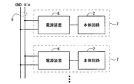
実施の形態1に係る電源装置6の構成例を説明する前に、図1のブロック図を参照して、その利用形態を例示する。
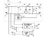
図2は電源装置6の構成を例示するブロック図である。図2に示すように、電源装置6は上記電源機能を実現する電源回路10を含んでいる。図2に例示の電源回路10は、DC/DCコンバータであり、非絶縁型、スイッチング型および降圧型に分類される。電源回路10は、図2の例によれば、電圧入力端部20と、スイッチング回路30と、ダイオード40と、インダクタ50と、コンデンサ60と、電圧検出器70と、電圧出力端部80とを含んでいる。
図2に示すように、電源装置6はさらに、電圧検出器100と、電力情報生成手段310と、電力情報出力端部320とを含んでおり、これらは電力情報生成機能に関連する。なお、図面では「電力情報生成手段」を「電力情報生成」と略記しており、かかる表記方法は他の要素についても用いる場合がある。
電源装置6によれば、電力情報PIの生成にトランジスタ31のスイッチング動作の内容を利用することによって、電流検出器を不要にしている。これにより、コスト、サイズ、消費電力等を削減することができる。
図4は第2の実施の形態に係る電源装置6Bの構成を例示するブロック図である。なお、電源装置6Bも本体回路2(図1参照)と組み合わせ可能である。
図5は第3の実施の形態に係る電源装置6Cの構成を例示するブロック図である。なお、電源装置6Cも本体回路2(図1参照)と組み合わせ可能である。
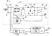
図6は第4の実施の形態に係る電源装置6Dの構成を例示するブロック図である。なお、電源装置6Dも本体回路2(図1参照)と組み合わせ可能である。電源装置6Dは、上記の電源機能および電力情報生成機能に加え、電力線5を利用したPLCを行う通信機能を有している。
図7は第5の実施の形態に係る電源装置6Eの構成を例示するブロック図である。なお、電源装置6Eも本体回路2(図1参照)と組み合わせ可能である。
図9は第6の実施の形態に係る電源装置6Fの構成を例示するブロック図である。なお、電源装置6Fも本体回路2(図1参照)と組み合わせ可能である。
図10は第7の実施の形態に係る電源装置6Gの構成を例示するブロック図である。なお、電源装置6Gも本体回路2(図1参照)と組み合わせ可能である。
なお、上記では電源回路10(図2参照)等が降圧型である場合を例示したが、昇圧型または昇降圧型の電源回路を採用することも可能である。
6,6B〜6G 電源装置
10,10F 電源回路
20 電圧入力端部
31 スイッチング手段
32 制御回路
70,100 電圧検出器
80 電圧出力端部
110 PLC処理回路
310 電力情報生成手段
311,311B,311C 導出手段
S31 スイッチング制御信号
PI 電力情報
Claims (6)
- 電圧入力端部に印加された入力電圧を所定電圧値の電圧に変換する電圧変換を行い、前記電圧変換後の電圧を電圧出力端部に出力する電源回路と、
前記電圧出力端部から出力される電力に関連した電力情報を生成する電力情報生成手段と
を備え、
前記電源回路は、
スイッチング動作によって前記電圧入力端部の側の電圧に対するチョッピングを行うスイッチング手段と、
前記スイッチング手段の前記スイッチング動作を制御する制御回路と
を含み、
前記電力情報生成手段は、前記スイッチング動作の内容に基づいて前記電力情報を生成し、
前記制御回路は、スイッチング制御信号を前記スイッチング手段に与えることによって前記スイッチング動作を制御し、
前記電力情報生成手段は、
前記スイッチング動作の内容を少なくとも含む所定情報と前記電力情報との関係が規定された導出手段を有し、
前記スイッチング制御信号を取得し、前記スイッチング制御信号から得られる前記スイッチング動作の内容を前記導出手段に当てはめることによって前記電力情報を導出し、
前記チョッピングが施された後の電圧を検出するように設けられた電圧検出器
をさらに備え、
前記所定情報は、前記電圧検出器による検出箇所の電圧値をさらに含み、
前記電力情報生成手段は、前記電圧検出器によって検出された電圧値と、前記スイッチング動作の内容とを前記導出手段に当てはめることによって前記電力情報を導出し、
前記制御回路は、前記電圧検出器によって検出された前記電圧値に基づいて前記スイッチング動作をフィードバック制御する、
電源装置。 - 請求項1に記載の電源装置であって、
前記電圧検出器は前記電圧出力端部の電圧を検出するように設けられている、
電源装置。 - 電圧入力端部に印加された入力電圧を所定電圧値の電圧に変換する電圧変換を行い、前記電圧変換後の電圧を電圧出力端部に出力する電源回路と、
前記電圧出力端部から出力される電力に関連した電力情報を生成する電力情報生成手段と
を備え、
前記電源回路は、
スイッチング動作によって前記電圧入力端部の側の電圧に対するチョッピングを行うスイッチング手段と、
前記スイッチング手段の前記スイッチング動作を制御する制御回路と
を含み、
前記電力情報生成手段は、前記スイッチング動作の内容に基づいて前記電力情報を生成し、
前記制御回路は、スイッチング制御信号を前記スイッチング手段に与えることによって前記スイッチング動作を制御し、
前記電力情報生成手段は、
前記スイッチング動作の内容を少なくとも含む所定情報と前記電力情報との関係が規定された導出手段を有し、
前記スイッチング制御信号を取得し、前記スイッチング制御信号から得られる前記スイッチング動作の内容を前記導出手段に当てはめることによって前記電力情報を導出し、
前記電源回路は、DC/DCコンバータであり、
前記所定情報は、前記スイッチング動作の内容のみを含み、
前記電力情報生成手段は、前記導出手段を用いて、前記スイッチング制御信号から得られる前記スイッチング動作の内容のみから前記電力情報を生成する、
電源装置。 - 請求項1ないし請求項3のうちのいずれか1つに記載の電源装置であって、
前記電圧入力端部に通じる電力線を利用して電力線通信(PLC)を行う、
電源装置。 - 請求項1または請求項2に記載の電源装置であって、
前記電圧入力端部に通じる電力線を利用して電力線通信(PLC)を行い、
前記電圧検出器によって検出された前記電圧値から、他の装置によって前記電力線へ送信されたデータを抽出する受信データ抽出処理を行うPLC処理回路
をさらに備える、電源装置。 - 請求項4または請求項5に記載の電源装置であって、
前記制御回路は前記PLCによる送信データに応じて前記スイッチング動作を変調する、
電源装置。
Priority Applications (4)
| Application Number | Priority Date | Filing Date | Title |
|---|---|---|---|
| JP2010258716A JP5487084B2 (ja) | 2010-11-19 | 2010-11-19 | 電源装置 |
| US13/882,896 US20130234690A1 (en) | 2010-11-19 | 2011-05-23 | Power supply device |
| CN201180055261.8A CN103201638B (zh) | 2010-11-19 | 2011-05-23 | 电源装置 |
| PCT/JP2011/061718 WO2012066807A1 (ja) | 2010-11-19 | 2011-05-23 | 電源装置 |
Applications Claiming Priority (1)
| Application Number | Priority Date | Filing Date | Title |
|---|---|---|---|
| JP2010258716A JP5487084B2 (ja) | 2010-11-19 | 2010-11-19 | 電源装置 |
Publications (3)
| Publication Number | Publication Date |
|---|---|
| JP2012108071A JP2012108071A (ja) | 2012-06-07 |
| JP2012108071A5 JP2012108071A5 (ja) | 2013-04-18 |
| JP5487084B2 true JP5487084B2 (ja) | 2014-05-07 |
Family
ID=46083752
Family Applications (1)
| Application Number | Title | Priority Date | Filing Date |
|---|---|---|---|
| JP2010258716A Expired - Fee Related JP5487084B2 (ja) | 2010-11-19 | 2010-11-19 | 電源装置 |
Country Status (4)
| Country | Link |
|---|---|
| US (1) | US20130234690A1 (ja) |
| JP (1) | JP5487084B2 (ja) |
| CN (1) | CN103201638B (ja) |
| WO (1) | WO2012066807A1 (ja) |
Families Citing this family (4)
| Publication number | Priority date | Publication date | Assignee | Title |
|---|---|---|---|---|
| JP2014032176A (ja) * | 2012-07-13 | 2014-02-20 | Ricoh Co Ltd | 電力検知装置 |
| KR102456266B1 (ko) | 2013-07-16 | 2022-10-18 | 라이온 세미컨덕터 인크. | 재구성 가능한 전력 조정기 |
| DE102016219742A1 (de) * | 2016-10-11 | 2018-04-12 | Robert Bosch Gmbh | Regelvorrichtung für einen Gleichspannungswandler, Gleichspannungswandler und Verfahren zur Regelung eines Gleichspannungswandlers |
| JP6536552B2 (ja) * | 2016-12-12 | 2019-07-03 | トヨタ自動車株式会社 | 太陽光発電システム |
Family Cites Families (27)
| Publication number | Priority date | Publication date | Assignee | Title |
|---|---|---|---|---|
| AT392177B (de) * | 1984-05-04 | 1991-02-11 | Siemens Ag | Vorrichtung zur erfassung der momentanleistung an einer phase eines wechselrichters mit vorgegebener eingangsgleichspannung, insbesondere eines pulswechselrichters |
| JPS6151574A (ja) * | 1984-08-21 | 1986-03-14 | Yaskawa Electric Mfg Co Ltd | インバ−タ出力電力検出方式 |
| US5045771A (en) * | 1987-10-15 | 1991-09-03 | Ascom Hasler Ag | Method and circuit for preventing transients from damaging a switching regulator |
| US5359281A (en) * | 1992-06-08 | 1994-10-25 | Motorola, Inc. | Quick-start and overvoltage protection for a switching regulator circuit |
| DE4338714C2 (de) * | 1993-11-12 | 2000-06-21 | Bosch Gmbh Robert | Schaltungsanordnung zur Strommessung über einen Schalttransistor |
| US5877611A (en) * | 1996-10-09 | 1999-03-02 | Lucent Technologies Inc. | Simple and efficient switching regulator for fast transient loads such as microprocessors |
| JP3290946B2 (ja) * | 1998-03-10 | 2002-06-10 | 株式会社東芝 | 電力演算装置 |
| JP2001078439A (ja) * | 1999-09-06 | 2001-03-23 | Murata Mfg Co Ltd | スイッチング電源装置 |
| FR2819364B1 (fr) * | 2001-01-08 | 2003-04-11 | Cit Alcatel | Dispositif de telealementation d'uin terminal dans un reseau de telecommunication, concentrateur, et repeteur comportant un tel dispositif |
| JP2002354510A (ja) * | 2001-05-30 | 2002-12-06 | Matsushita Electric Ind Co Ltd | 消費電力表示装置 |
| KR100484160B1 (ko) * | 2002-09-06 | 2005-04-19 | 삼성전자주식회사 | 소비 전력 표시 장치 |
| JP4310113B2 (ja) * | 2003-01-16 | 2009-08-05 | 三菱電機株式会社 | 電力関連量計測装置 |
| CA2484951A1 (en) * | 2004-09-27 | 2006-03-27 | Veris Industries, Llc | Method and apparatus for phase determination |
| CA2483378A1 (en) * | 2004-10-01 | 2006-04-01 | Aleksandar Prodic | A digital controller for dc-dc switching converters that allows operation at ultra-high constant switching frequencies |
| JP4423157B2 (ja) * | 2004-10-06 | 2010-03-03 | キヤノン株式会社 | 電力線通信装置およびその制御方法 |
| JP2006184063A (ja) * | 2004-12-27 | 2006-07-13 | Matsushita Electric Ind Co Ltd | 電力監視システム |
| US7554473B2 (en) * | 2007-05-02 | 2009-06-30 | Cirrus Logic, Inc. | Control system using a nonlinear delta-sigma modulator with nonlinear process modeling |
| US20080283118A1 (en) * | 2007-05-17 | 2008-11-20 | Larankelo, Inc. | Photovoltaic ac inverter mount and interconnect |
| US7902800B2 (en) * | 2007-07-13 | 2011-03-08 | Chil Semiconductor Corporation | Adaptive power supply and related circuitry |
| US8024138B2 (en) * | 2008-02-01 | 2011-09-20 | International Rectifier Corporation | Power supply circuitry, collection and reporting of power supply parameter information |
| US8085024B2 (en) * | 2008-04-29 | 2011-12-27 | Exar Corporation | Self-tuning digital current estimator for low-power switching converters |
| US20090306914A1 (en) * | 2008-06-04 | 2009-12-10 | Texas Instruments Incorporated | System and method for measuring input power of power supplies |
| JP4755229B2 (ja) * | 2008-07-23 | 2011-08-24 | レノボ・シンガポール・プライベート・リミテッド | 電子機器の電力計測システム |
| US8922189B2 (en) * | 2008-11-18 | 2014-12-30 | Texas Instruments Incorporated | Controlled on-time buck PFC |
| WO2010146676A1 (ja) * | 2009-06-17 | 2010-12-23 | Necディスプレイソリューションズ株式会社 | 液晶モニタの消費電力表示方法および消費電力表示装置 |
| US8390261B2 (en) * | 2010-05-21 | 2013-03-05 | Infineon Technologies Austria Ag | Maximum power point tracker bypass |
| TW201217961A (en) * | 2010-10-20 | 2012-05-01 | Hon Hai Prec Ind Co Ltd | Conversion efficiency testing device and using the same |
-
2010
- 2010-11-19 JP JP2010258716A patent/JP5487084B2/ja not_active Expired - Fee Related
-
2011
- 2011-05-23 US US13/882,896 patent/US20130234690A1/en not_active Abandoned
- 2011-05-23 WO PCT/JP2011/061718 patent/WO2012066807A1/ja active Application Filing
- 2011-05-23 CN CN201180055261.8A patent/CN103201638B/zh not_active Expired - Fee Related
Also Published As
| Publication number | Publication date |
|---|---|
| CN103201638A (zh) | 2013-07-10 |
| CN103201638B (zh) | 2015-08-05 |
| WO2012066807A1 (ja) | 2012-05-24 |
| JP2012108071A (ja) | 2012-06-07 |
| US20130234690A1 (en) | 2013-09-12 |
Similar Documents
| Publication | Publication Date | Title |
|---|---|---|
| JP5498347B2 (ja) | Plc/電源ハイブリッド装置および通信機能付き装置 | |
| JP5487084B2 (ja) | 電源装置 | |
| TWI502865B (zh) | Soft start switching power converter means | |
| JP2009222433A (ja) | 電力測定システム | |
| TW201535947A (zh) | 開關式電源供應器 | |
| JP2010032395A (ja) | 接触不良検出装置およびスイッチング電源 | |
| EP2799948B1 (en) | Power supply device and power supply switching method | |
| TW201417466A (zh) | 具初級側回授控制之返馳式電壓轉換器及其電壓控制方法 | |
| JP4854556B2 (ja) | 電源装置 | |
| GB2578033A (en) | A DC-DC converter | |
| JP6195273B2 (ja) | 電力変換回路の制御装置 | |
| TW201029303A (en) | Current mode DC-DC converter | |
| JP5830966B2 (ja) | 電子機器の消費電力検出回路、消費電力検出方法 | |
| JP2006184063A (ja) | 電力監視システム | |
| KR20140018489A (ko) | 단상 디씨/디씨 벅 컨버터의 인덕터 전류 추정 장치 및 방법 | |
| TWI469484B (zh) | 熱能利用電路、電子裝置及方法 | |
| CN103609011A (zh) | 用于三相交流电压-直流电压转换器的简易控制方法 | |
| CN111025107A (zh) | 故障电弧检测电路、装置及工况检测方法 | |
| JP5194666B2 (ja) | 電源装置 | |
| TWI601366B (zh) | 電源供應器及電壓校正方法 | |
| JP2015095964A (ja) | フライバックコンバータの出力電流検出方法 | |
| JP6890302B2 (ja) | 電力変換システム | |
| TW201015840A (en) | Method and apparatus of input voltage estimation for power factor corrector | |
| JP2019080415A (ja) | Llc構造でのpsr電流制御システム | |
| JP2017192265A (ja) | スイッチング電源装置およびスイッチング制御回路 |
Legal Events
| Date | Code | Title | Description |
|---|---|---|---|
| A521 | Written amendment |
Free format text: JAPANESE INTERMEDIATE CODE: A523 Effective date: 20130301 |
|
| A621 | Written request for application examination |
Free format text: JAPANESE INTERMEDIATE CODE: A621 Effective date: 20130301 |
|
| A131 | Notification of reasons for refusal |
Free format text: JAPANESE INTERMEDIATE CODE: A131 Effective date: 20131126 |
|
| A521 | Written amendment |
Free format text: JAPANESE INTERMEDIATE CODE: A523 Effective date: 20140116 |
|
| TRDD | Decision of grant or rejection written | ||
| A01 | Written decision to grant a patent or to grant a registration (utility model) |
Free format text: JAPANESE INTERMEDIATE CODE: A01 Effective date: 20140204 |
|
| A61 | First payment of annual fees (during grant procedure) |
Free format text: JAPANESE INTERMEDIATE CODE: A61 Effective date: 20140224 |
|
| R150 | Certificate of patent or registration of utility model |
Ref document number: 5487084 Country of ref document: JP Free format text: JAPANESE INTERMEDIATE CODE: R150 |
|
| R250 | Receipt of annual fees |
Free format text: JAPANESE INTERMEDIATE CODE: R250 |
|
| R250 | Receipt of annual fees |
Free format text: JAPANESE INTERMEDIATE CODE: R250 |
|
| R250 | Receipt of annual fees |
Free format text: JAPANESE INTERMEDIATE CODE: R250 |
|
| LAPS | Cancellation because of no payment of annual fees |