JP4635896B2 - 車両用ブレーキ制御装置 - Google Patents
車両用ブレーキ制御装置 Download PDFInfo
- Publication number
- JP4635896B2 JP4635896B2 JP2006037993A JP2006037993A JP4635896B2 JP 4635896 B2 JP4635896 B2 JP 4635896B2 JP 2006037993 A JP2006037993 A JP 2006037993A JP 2006037993 A JP2006037993 A JP 2006037993A JP 4635896 B2 JP4635896 B2 JP 4635896B2
- Authority
- JP
- Japan
- Prior art keywords
- motor
- cylinder pressure
- target
- pressure
- wheel cylinder
- Prior art date
- Legal status (The legal status is an assumption and is not a legal conclusion. Google has not performed a legal analysis and makes no representation as to the accuracy of the status listed.)
- Expired - Fee Related
Links
Images


Classifications
-
- B—PERFORMING OPERATIONS; TRANSPORTING
- B60—VEHICLES IN GENERAL
- B60T—VEHICLE BRAKE CONTROL SYSTEMS OR PARTS THEREOF; BRAKE CONTROL SYSTEMS OR PARTS THEREOF, IN GENERAL; ARRANGEMENT OF BRAKING ELEMENTS ON VEHICLES IN GENERAL; PORTABLE DEVICES FOR PREVENTING UNWANTED MOVEMENT OF VEHICLES; VEHICLE MODIFICATIONS TO FACILITATE COOLING OF BRAKES
- B60T13/00—Transmitting braking action from initiating means to ultimate brake actuator with power assistance or drive; Brake systems incorporating such transmitting means, e.g. air-pressure brake systems
- B60T13/10—Transmitting braking action from initiating means to ultimate brake actuator with power assistance or drive; Brake systems incorporating such transmitting means, e.g. air-pressure brake systems with fluid assistance, drive, or release
- B60T13/12—Transmitting braking action from initiating means to ultimate brake actuator with power assistance or drive; Brake systems incorporating such transmitting means, e.g. air-pressure brake systems with fluid assistance, drive, or release the fluid being liquid
- B60T13/16—Transmitting braking action from initiating means to ultimate brake actuator with power assistance or drive; Brake systems incorporating such transmitting means, e.g. air-pressure brake systems with fluid assistance, drive, or release the fluid being liquid using pumps directly, i.e. without interposition of accumulators or reservoirs
- B60T13/18—Transmitting braking action from initiating means to ultimate brake actuator with power assistance or drive; Brake systems incorporating such transmitting means, e.g. air-pressure brake systems with fluid assistance, drive, or release the fluid being liquid using pumps directly, i.e. without interposition of accumulators or reservoirs with control of pump output delivery, e.g. by distributor valves
-
- B—PERFORMING OPERATIONS; TRANSPORTING
- B60—VEHICLES IN GENERAL
- B60T—VEHICLE BRAKE CONTROL SYSTEMS OR PARTS THEREOF; BRAKE CONTROL SYSTEMS OR PARTS THEREOF, IN GENERAL; ARRANGEMENT OF BRAKING ELEMENTS ON VEHICLES IN GENERAL; PORTABLE DEVICES FOR PREVENTING UNWANTED MOVEMENT OF VEHICLES; VEHICLE MODIFICATIONS TO FACILITATE COOLING OF BRAKES
- B60T8/00—Arrangements for adjusting wheel-braking force to meet varying vehicular or ground-surface conditions, e.g. limiting or varying distribution of braking force
- B60T8/32—Arrangements for adjusting wheel-braking force to meet varying vehicular or ground-surface conditions, e.g. limiting or varying distribution of braking force responsive to a speed condition, e.g. acceleration or deceleration
- B60T8/34—Arrangements for adjusting wheel-braking force to meet varying vehicular or ground-surface conditions, e.g. limiting or varying distribution of braking force responsive to a speed condition, e.g. acceleration or deceleration having a fluid pressure regulator responsive to a speed condition
- B60T8/40—Arrangements for adjusting wheel-braking force to meet varying vehicular or ground-surface conditions, e.g. limiting or varying distribution of braking force responsive to a speed condition, e.g. acceleration or deceleration having a fluid pressure regulator responsive to a speed condition comprising an additional fluid circuit including fluid pressurising means for modifying the pressure of the braking fluid, e.g. including wheel driven pumps for detecting a speed condition, or pumps which are controlled by means independent of the braking system
- B60T8/404—Control of the pump unit
- B60T8/4059—Control of the pump unit involving the rate of delivery
-
- B—PERFORMING OPERATIONS; TRANSPORTING
- B60—VEHICLES IN GENERAL
- B60T—VEHICLE BRAKE CONTROL SYSTEMS OR PARTS THEREOF; BRAKE CONTROL SYSTEMS OR PARTS THEREOF, IN GENERAL; ARRANGEMENT OF BRAKING ELEMENTS ON VEHICLES IN GENERAL; PORTABLE DEVICES FOR PREVENTING UNWANTED MOVEMENT OF VEHICLES; VEHICLE MODIFICATIONS TO FACILITATE COOLING OF BRAKES
- B60T8/00—Arrangements for adjusting wheel-braking force to meet varying vehicular or ground-surface conditions, e.g. limiting or varying distribution of braking force
- B60T8/32—Arrangements for adjusting wheel-braking force to meet varying vehicular or ground-surface conditions, e.g. limiting or varying distribution of braking force responsive to a speed condition, e.g. acceleration or deceleration
- B60T8/34—Arrangements for adjusting wheel-braking force to meet varying vehicular or ground-surface conditions, e.g. limiting or varying distribution of braking force responsive to a speed condition, e.g. acceleration or deceleration having a fluid pressure regulator responsive to a speed condition
- B60T8/40—Arrangements for adjusting wheel-braking force to meet varying vehicular or ground-surface conditions, e.g. limiting or varying distribution of braking force responsive to a speed condition, e.g. acceleration or deceleration having a fluid pressure regulator responsive to a speed condition comprising an additional fluid circuit including fluid pressurising means for modifying the pressure of the braking fluid, e.g. including wheel driven pumps for detecting a speed condition, or pumps which are controlled by means independent of the braking system
- B60T8/4072—Systems in which a driver input signal is used as a control signal for the additional fluid circuit which is normally used for braking
- B60T8/4081—Systems with stroke simulating devices for driver input
-
- B—PERFORMING OPERATIONS; TRANSPORTING
- B60—VEHICLES IN GENERAL
- B60T—VEHICLE BRAKE CONTROL SYSTEMS OR PARTS THEREOF; BRAKE CONTROL SYSTEMS OR PARTS THEREOF, IN GENERAL; ARRANGEMENT OF BRAKING ELEMENTS ON VEHICLES IN GENERAL; PORTABLE DEVICES FOR PREVENTING UNWANTED MOVEMENT OF VEHICLES; VEHICLE MODIFICATIONS TO FACILITATE COOLING OF BRAKES
- B60T2270/00—Further aspects of brake control systems not otherwise provided for
- B60T2270/82—Brake-by-Wire, EHB
Landscapes
- Engineering & Computer Science (AREA)
- Physics & Mathematics (AREA)
- Fluid Mechanics (AREA)
- Transportation (AREA)
- Mechanical Engineering (AREA)
- Regulating Braking Force (AREA)
Description
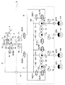
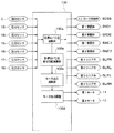
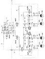
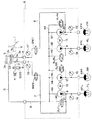
本発明の一実施形態を適用した車両用ブレーキ制御装置の油圧回路構成を図1に示す。また、図2に、本実施形態の車両用ブレーキ制御装置の制御系を司るブレーキECU100の信号の入出力の関係を示す。以下、これらの図を参照して、本実施形態の車両用ブレーキ制御装置の構成について説明する。ここでは右前輪−左後輪、左前輪−右後輪の各配管系統を備えるX配管の油圧回路を構成する車両に本実施形態の車両用ブレーキ制御装置を適用した例について説明する。
第1、第2モータ11、12を安定して回転させられる回転数、言い換えると第1〜第4リニア弁SLFR、SLRL、SLFL、SLRRでの調圧作用が安定して行える回転数(以下、モータ安定回転数という)は、第1、第2モータ11、12の特性などによって決まっている。そして、このモータ安定回転数を得るために必要な第1モータ出力デューティは、第1、第2モータ11、12のトルクに応じて変化する。
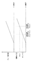
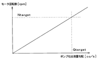
図5は、目標W/C圧とその目標W/C圧を発生させるために必要となるブレーキ液量の関係を示した特性図である。この図に示されるように、目標W/C圧を発生させるために必要となるブレーキ液量が決まっているため、目標W/C圧変化勾配演算部100bで記憶した前回の演算タイミング(n−1)で演算された目標W/C圧P(n−1)および今回の演算タイミングT(n)で演算された目標W/C圧P(n)と対応するブレーキ液量V(n−1)、V(n)を図5から求める。そして、それぞれに対応するブレーキ液量V(n−1)、V(n)の差分ΔVを演算間隔ΔTで割った値ΔV/ΔT[cc/s]として、目標W/C圧変化勾配ΔP/ΔTを達成するために必要なポンプ吐出液量勾配Qtargetが求められる。
Ntarget=Qtarget×60/Vpump[rpm]
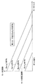
この回転数Ntargetが、目標W/C圧変化勾配演算部100bで演算された目標W/C圧変化勾配ΔP/ΔTを達成するために必要なモータ回転数となる。そして、この回転数Ntargetを達成するために必要な第2モータ出力デューティは、図7に示すモータトルク−モータ回転数の特性図を利用して、目標W/C圧演算部100aにて今回の演算タイミングT(n)で求めた目標W/C圧P(n)に相当するトルクと回転数Ntargetの交差する点が属する特性線として求められる。
通常ブレーキ時には、ブレーキペダル1が踏み込まれて踏力センサ2の検出信号がブレーキECU100に入力されると、ブレーキECU100は、図8に示すような駆動形態となるように各種制御弁SCSS、SNO1、SNO2、SWC1、SWC2、SLFR、SLRL、SLFL、SLRRや第1、第2モータ11、12を駆動する。
異常時には、ブレーキECU100から制御信号が出力できなくなるか、もしくは、各種制御弁SCSS、SNO1、SNO2、SWC1、SWC2、SLFR、SLRL、SLFL、SLRRや第1、第2モータ11、12が正常に駆動されない可能性がある。このため、各種制御弁SCSS、SNO1、SNO2、SWC1、SWC2、SLFR、SLRL、SLFL、SLRRや第1、第2モータ11、12すべてに関して、図8に示されるように通電がOFFされる。
本発明の第2実施形態について説明する。本実施形態は、第1実施形態に対して車両用ブレーキ制御装置の構成を一部変更したものであり、基本的には第1実施形態と同様の構成となっているため、第1実施形態と異なる部分についてのみ説明する。
本発明の第3実施形態について説明する。本実施形態は、第2実施形態に対して車両用ブレーキ制御装置の構成を一部変更したものであり、基本的には第2実施形態と同様の構成となっているため、第2実施形態と異なる部分についてのみ説明する。
図1に示した車両用ブレーキ制御装置は、本発明を適用できるブレーキ構成例として示したものであり、図1に示したものに限定されるものではなく、様々な形態で変更可能である。
Claims (3)
- ドライバによって操作されるブレーキ操作部材(1)と、
前記ブレーキ操作部材の操作量を検出する操作量センサ(2)と、
2つの前輪(FR、FL)それぞれに対応して設けられた前輪用第1、第2ホイールシリンダ(6FR、6FL)、および、2つの後輪(RL、RR)それぞれに対応して設けられた後輪用第1、第2ホイールシリンダ(6RL、6RR)と、
ブレーキ液を貯留しているリザーバ(3f)と、
前記リザーバと前記前輪用第1、第2および前記後輪用第1、第2ホイールシリンダをつなぎ、前記前輪用第1、第2および前記後輪用第1、第2ホイールシリンダそれぞれに接続されるように4つに分岐された主管路(C、G、G1〜G4)と、
前記主管路のうち4つに分岐された部位(G1〜G4)それぞれに対して1つずつ配置され、前記リザーバに貯留されたブレーキ液を吸入・吐出して、前記前輪用第1、第2および後輪用第1、第2ホイールシリンダそれぞれを加圧する第1〜第4ポンプ(7〜10)と、
前記第1、第2ポンプ(7、8)により加圧される系統を第1配管系統として、該第1配管系統に備えられた前記第1、第2ポンプを駆動するための第1モータ(11)と、
前記第3、第4ポンプ(9、10)により加圧される系統を第2配管系統として、該第2配管系統に備えられた前記第3、第4ポンプを駆動するための第2モータ(12)と、
前記第1〜第4ポンプに並列的に配置され、前記リザーバへブレーキ液を返流する管路となる第1〜第4調圧回路(H1〜H4)と、
前記第1〜第4調圧回路にそれぞれ対応して配置された第1〜第4リニア弁(SLFR、SLRL、SLFL、SLRR)と、
前記操作量センサの検出信号に基づいて、前記第1〜第4リニア弁および前記第1、第2モータを駆動し、前記第1、第2モータに流す電流値を前記操作量センサにて検出された操作量に対応する目標ホイールシリンダ圧に応じた値に可変させる制御手段(100)と、を備えた車両用ブレーキ制御装置であって、
前記制御手段は、
前記操作量センサに基づいて前記ブレーキ操作部材が操作されたことを検出したときに、前記操作量センサにて検出された操作量に対応する目標ホイールシリンダ圧(P(n))を求める目標ホイールシリンダ圧演算部(100a)と、
前記目標ホイールシリンダ圧の変化勾配(ΔP/ΔT)を演算する目標ホイールシリンダ圧変化勾配演算部(100b)と、
前記目標ホイールシリンダ圧に基づいて、前記第1〜第4リニア弁が安定して調圧作用を行えるモータ安定回転数を得るために必要な前記第1、第2モータに出力する電流のデューティ比となる第1モータ出力デューティを求めると共に、前記目標ホイールシリンダ圧変化勾配を達成するために必要な前記第1、第2モータに出力する電流のデューティ比となる第2モータ出力デューティを求め、前記第1、第2モータ出力デューティのうちの大きい方を実際に出力するモータ出力デューティとして設定するモータ出力演算部(100c)と、
前記モータ出力演算部にて設定された前記モータ出力デューティに基づいて、前記第1、第2モータに対して流す電流を調整するモータ出力調整部(100d)と、を備えていることを特徴とする車両用ブレーキ制御装置。 - 前記モータ出力演算部は、前記目標ホイールシリンダ圧に対応するモータトルクを求め、モータトルク−モータ回転数特性に基づき、前記モータトルクと前記モータ安定回転数に対応する電流のデューティ比を前記第1モータ出力デューティとすることを特徴とする請求項1に記載の車両用ブレーキ制御装置。
- 前記目標ホイールシリンダ圧演算部は、前記目標ホイールシリンダ圧を演算周期毎に求め、
前記モータ出力演算部は、前記目標ホイールシリンダ圧演算部で演算された前記目標ホイールシリンダ圧に基づいて、前回の演算タイミング(T(n−1))で演算された目標ホイールシリンダ圧(P(n−1))を発生させるために必要となるブレーキ液量(V(n−1))と今回の演算タイミング(T(n))で演算された前記目標ホイールシリンダ圧(P(n))を発生させるために必要となるブレーキ液量(V(n))の差分(ΔV)を前記演算周期における演算間隔(ΔT)で割った値(ΔV/ΔT)を必要なポンプ吐出液量勾配(Qtarget)として求めたのち、該ポンプ吐出液量勾配と前記第1、第2モータの1回転当たりの前記第1〜第4ポンプのブレーキ液吐出量(Vpump)に基づいて、前記目標ホイールシリンダ圧変化勾配を達成するために必要なモータ回転数を求め、さらに、前記今回の演算タイミングで演算された目標ホイールシリンダ圧に対応するモータトルクを求め、モータトルク−モータ回転数特性に基づき、前記モータトルクと前記目標ホイールシリンダ圧変化勾配を達成するために必要なモータ回転数に対応する電流のデューティ比を前記第2モータ出力デューティとすることを特徴とする請求項1または2に記載の車両用ブレーキ制御装置。
Priority Applications (2)
| Application Number | Priority Date | Filing Date | Title |
|---|---|---|---|
| JP2006037993A JP4635896B2 (ja) | 2006-02-15 | 2006-02-15 | 車両用ブレーキ制御装置 |
| US11/702,502 US7621602B2 (en) | 2006-02-15 | 2007-02-06 | Vehicle brake control device |
Applications Claiming Priority (1)
| Application Number | Priority Date | Filing Date | Title |
|---|---|---|---|
| JP2006037993A JP4635896B2 (ja) | 2006-02-15 | 2006-02-15 | 車両用ブレーキ制御装置 |
Publications (2)
| Publication Number | Publication Date |
|---|---|
| JP2007216769A JP2007216769A (ja) | 2007-08-30 |
| JP4635896B2 true JP4635896B2 (ja) | 2011-02-23 |
Family
ID=38367638
Family Applications (1)
| Application Number | Title | Priority Date | Filing Date |
|---|---|---|---|
| JP2006037993A Expired - Fee Related JP4635896B2 (ja) | 2006-02-15 | 2006-02-15 | 車両用ブレーキ制御装置 |
Country Status (2)
| Country | Link |
|---|---|
| US (1) | US7621602B2 (ja) |
| JP (1) | JP4635896B2 (ja) |
Families Citing this family (10)
| Publication number | Priority date | Publication date | Assignee | Title |
|---|---|---|---|---|
| DE102004019511A1 (de) * | 2004-04-22 | 2005-11-10 | Zf Friedrichshafen Ag | Verfahren zur Steuerung einer Druckmittelpumpe in einem Kraftfahrzeug |
| JP4839791B2 (ja) * | 2005-11-18 | 2011-12-21 | 株式会社アドヴィックス | 車両用ブレーキ制御装置 |
| JP4696950B2 (ja) * | 2006-02-15 | 2011-06-08 | 株式会社アドヴィックス | 車両用ブレーキ制御装置 |
| JP4835203B2 (ja) * | 2006-03-01 | 2011-12-14 | 株式会社アドヴィックス | 車両用ブレーキ制御装置 |
| JP4618169B2 (ja) * | 2006-03-13 | 2011-01-26 | 株式会社アドヴィックス | 車両用ブレーキ制御装置 |
| DE102011077313A1 (de) * | 2011-06-09 | 2012-12-13 | Continental Teves Ag & Co. Ohg | Verfahren zum Betreiben einer Bremsanlage sowie Bremsanlage |
| KR101265951B1 (ko) * | 2011-06-28 | 2013-05-21 | 주식회사 만도 | 전자식 주차 브레이크 시스템의 제어 방법 |
| DE102013223861A1 (de) * | 2013-11-21 | 2015-05-21 | Continental Teves Ag & Co. Ohg | Bremsanlage für Kraftahrzeuge |
| US10106137B2 (en) | 2017-01-06 | 2018-10-23 | Ford Global Technologies, Llc | Adjustment of maximum brake pump speed based on rate of change of target deceleration |
| US10300899B2 (en) * | 2017-01-06 | 2019-05-28 | Ford Global Technologies, Llc | Adjustment of maximum brake pump speed based on rate of change of target deceleration |
Family Cites Families (15)
| Publication number | Priority date | Publication date | Assignee | Title |
|---|---|---|---|---|
| JPH0880830A (ja) * | 1994-09-09 | 1996-03-26 | Aisin Seiki Co Ltd | アンチスキッド制御装置 |
| US5487593A (en) * | 1994-11-23 | 1996-01-30 | Alliedsignal Inc. | Anti-lock braking system providing pump motor duty cycle based on deceleration and motor voltage feed back |
| JPH08142847A (ja) * | 1994-11-24 | 1996-06-04 | Toyota Motor Corp | ブレーキシステム |
| JP3828609B2 (ja) * | 1996-04-03 | 2006-10-04 | 本田技研工業株式会社 | アンチロックブレーキ装置 |
| JP3625115B2 (ja) | 1997-01-22 | 2005-03-02 | 株式会社日立ユニシアオートモティブ | 制動装置 |
| US6113197A (en) * | 1996-11-18 | 2000-09-05 | Unisia Jecs Corporation | Wheel braking system |
| DE69918202T2 (de) * | 1998-02-20 | 2005-07-07 | Denso Corp., Kariya | Bremssystem für Kraftfahrzeuge |
| JPH11301435A (ja) * | 1998-02-20 | 1999-11-02 | Denso Corp | ブレ―キ装置 |
| GB2344142B (en) * | 1998-11-27 | 2003-01-22 | Lucas Ind Plc | Pump motor control in electro-hydraulic braking systems |
| JP2001071877A (ja) * | 1999-09-09 | 2001-03-21 | Nissin Kogyo Co Ltd | 車両用アンチロックブレーキ制御装置 |
| US6291960B1 (en) * | 2000-03-22 | 2001-09-18 | Ford Global Technologies, Inc. | Pulse width modulated motor control system and method for reducing noise vibration and harshness |
| JP4276485B2 (ja) * | 2003-08-18 | 2009-06-10 | 株式会社日立製作所 | 車両姿勢制御装置 |
| JP4839791B2 (ja) * | 2005-11-18 | 2011-12-21 | 株式会社アドヴィックス | 車両用ブレーキ制御装置 |
| JP4835203B2 (ja) * | 2006-03-01 | 2011-12-14 | 株式会社アドヴィックス | 車両用ブレーキ制御装置 |
| JP5119646B2 (ja) * | 2006-03-06 | 2013-01-16 | 株式会社アドヴィックス | 車両用ブレーキ制御装置 |
-
2006
- 2006-02-15 JP JP2006037993A patent/JP4635896B2/ja not_active Expired - Fee Related
-
2007
- 2007-02-06 US US11/702,502 patent/US7621602B2/en not_active Expired - Fee Related
Also Published As
| Publication number | Publication date |
|---|---|
| US20070188015A1 (en) | 2007-08-16 |
| JP2007216769A (ja) | 2007-08-30 |
| US7621602B2 (en) | 2009-11-24 |
Similar Documents
| Publication | Publication Date | Title |
|---|---|---|
| JP4839791B2 (ja) | 車両用ブレーキ制御装置 | |
| US7887145B2 (en) | Vehicle brake control device | |
| JP5119646B2 (ja) | 車両用ブレーキ制御装置 | |
| JP4661621B2 (ja) | 車両用ブレーキ制御装置 | |
| JP5969933B2 (ja) | ブレーキ装置 | |
| US7621602B2 (en) | Vehicle brake control device | |
| JP6748537B2 (ja) | 電子式油圧ブレーキ装置 | |
| JP4618169B2 (ja) | 車両用ブレーキ制御装置 | |
| JP4696950B2 (ja) | 車両用ブレーキ制御装置 | |
| US8052226B2 (en) | Electronic control brake system having simulation function | |
| KR102530382B1 (ko) | 전자식 브레이크 시스템 및 제어 방법 | |
| CN106232441A (zh) | 制动控制装置、制动系统及制动液压产生方法 | |
| US20180194332A1 (en) | Brake Control Apparatus and Brake System | |
| JP6245696B2 (ja) | ブレーキ液圧発生装置 | |
| JP2011051494A (ja) | ブレーキ制御装置 | |
| JP2007216772A (ja) | 車両用ブレーキ制御装置 | |
| JP4696949B2 (ja) | 車両用ブレーキ制御装置 | |
| US20070208481A1 (en) | Vehicle brake control device | |
| JP2007216765A (ja) | 制動力保持制御装置 | |
| JP4816121B2 (ja) | 車両用ブレーキ制御装置 | |
| JP5565008B2 (ja) | 制動制御装置 | |
| JP2011100199A (ja) | 電流供給回路およびブレーキ制御装置 | |
| JP4760431B2 (ja) | 車両用ブレーキ制御装置 | |
| JP5977691B2 (ja) | ブレーキ制御装置 | |
| JP2007216770A (ja) | 車両用ブレーキ制御装置 |
Legal Events
| Date | Code | Title | Description |
|---|---|---|---|
| A621 | Written request for application examination |
Free format text: JAPANESE INTERMEDIATE CODE: A621 Effective date: 20080806 |
|
| A977 | Report on retrieval |
Free format text: JAPANESE INTERMEDIATE CODE: A971007 Effective date: 20100915 |
|
| TRDD | Decision of grant or rejection written | ||
| A01 | Written decision to grant a patent or to grant a registration (utility model) |
Free format text: JAPANESE INTERMEDIATE CODE: A01 Effective date: 20101026 |
|
| A01 | Written decision to grant a patent or to grant a registration (utility model) |
Free format text: JAPANESE INTERMEDIATE CODE: A01 |
|
| A61 | First payment of annual fees (during grant procedure) |
Free format text: JAPANESE INTERMEDIATE CODE: A61 Effective date: 20101108 |
|
| FPAY | Renewal fee payment (event date is renewal date of database) |
Free format text: PAYMENT UNTIL: 20131203 Year of fee payment: 3 |
|
| R150 | Certificate of patent or registration of utility model |
Free format text: JAPANESE INTERMEDIATE CODE: R150 |
|
| LAPS | Cancellation because of no payment of annual fees |