JP4635896B2 - Brake control device for vehicle - Google Patents
Brake control device for vehicle Download PDFInfo
- Publication number
- JP4635896B2 JP4635896B2 JP2006037993A JP2006037993A JP4635896B2 JP 4635896 B2 JP4635896 B2 JP 4635896B2 JP 2006037993 A JP2006037993 A JP 2006037993A JP 2006037993 A JP2006037993 A JP 2006037993A JP 4635896 B2 JP4635896 B2 JP 4635896B2
- Authority
- JP
- Japan
- Prior art keywords
- motor
- cylinder pressure
- target
- pressure
- wheel cylinder
- Prior art date
- Legal status (The legal status is an assumption and is not a legal conclusion. Google has not performed a legal analysis and makes no representation as to the accuracy of the status listed.)
- Expired - Fee Related
Links
Images


Classifications
-
- B—PERFORMING OPERATIONS; TRANSPORTING
- B60—VEHICLES IN GENERAL
- B60T—VEHICLE BRAKE CONTROL SYSTEMS OR PARTS THEREOF; BRAKE CONTROL SYSTEMS OR PARTS THEREOF, IN GENERAL; ARRANGEMENT OF BRAKING ELEMENTS ON VEHICLES IN GENERAL; PORTABLE DEVICES FOR PREVENTING UNWANTED MOVEMENT OF VEHICLES; VEHICLE MODIFICATIONS TO FACILITATE COOLING OF BRAKES
- B60T13/00—Transmitting braking action from initiating means to ultimate brake actuator with power assistance or drive; Brake systems incorporating such transmitting means, e.g. air-pressure brake systems
- B60T13/10—Transmitting braking action from initiating means to ultimate brake actuator with power assistance or drive; Brake systems incorporating such transmitting means, e.g. air-pressure brake systems with fluid assistance, drive, or release
- B60T13/12—Transmitting braking action from initiating means to ultimate brake actuator with power assistance or drive; Brake systems incorporating such transmitting means, e.g. air-pressure brake systems with fluid assistance, drive, or release the fluid being liquid
- B60T13/16—Transmitting braking action from initiating means to ultimate brake actuator with power assistance or drive; Brake systems incorporating such transmitting means, e.g. air-pressure brake systems with fluid assistance, drive, or release the fluid being liquid using pumps directly, i.e. without interposition of accumulators or reservoirs
- B60T13/18—Transmitting braking action from initiating means to ultimate brake actuator with power assistance or drive; Brake systems incorporating such transmitting means, e.g. air-pressure brake systems with fluid assistance, drive, or release the fluid being liquid using pumps directly, i.e. without interposition of accumulators or reservoirs with control of pump output delivery, e.g. by distributor valves
-
- B—PERFORMING OPERATIONS; TRANSPORTING
- B60—VEHICLES IN GENERAL
- B60T—VEHICLE BRAKE CONTROL SYSTEMS OR PARTS THEREOF; BRAKE CONTROL SYSTEMS OR PARTS THEREOF, IN GENERAL; ARRANGEMENT OF BRAKING ELEMENTS ON VEHICLES IN GENERAL; PORTABLE DEVICES FOR PREVENTING UNWANTED MOVEMENT OF VEHICLES; VEHICLE MODIFICATIONS TO FACILITATE COOLING OF BRAKES
- B60T8/00—Arrangements for adjusting wheel-braking force to meet varying vehicular or ground-surface conditions, e.g. limiting or varying distribution of braking force
- B60T8/32—Arrangements for adjusting wheel-braking force to meet varying vehicular or ground-surface conditions, e.g. limiting or varying distribution of braking force responsive to a speed condition, e.g. acceleration or deceleration
- B60T8/34—Arrangements for adjusting wheel-braking force to meet varying vehicular or ground-surface conditions, e.g. limiting or varying distribution of braking force responsive to a speed condition, e.g. acceleration or deceleration having a fluid pressure regulator responsive to a speed condition
- B60T8/40—Arrangements for adjusting wheel-braking force to meet varying vehicular or ground-surface conditions, e.g. limiting or varying distribution of braking force responsive to a speed condition, e.g. acceleration or deceleration having a fluid pressure regulator responsive to a speed condition comprising an additional fluid circuit including fluid pressurising means for modifying the pressure of the braking fluid, e.g. including wheel driven pumps for detecting a speed condition, or pumps which are controlled by means independent of the braking system
- B60T8/404—Control of the pump unit
- B60T8/4059—Control of the pump unit involving the rate of delivery
-
- B—PERFORMING OPERATIONS; TRANSPORTING
- B60—VEHICLES IN GENERAL
- B60T—VEHICLE BRAKE CONTROL SYSTEMS OR PARTS THEREOF; BRAKE CONTROL SYSTEMS OR PARTS THEREOF, IN GENERAL; ARRANGEMENT OF BRAKING ELEMENTS ON VEHICLES IN GENERAL; PORTABLE DEVICES FOR PREVENTING UNWANTED MOVEMENT OF VEHICLES; VEHICLE MODIFICATIONS TO FACILITATE COOLING OF BRAKES
- B60T8/00—Arrangements for adjusting wheel-braking force to meet varying vehicular or ground-surface conditions, e.g. limiting or varying distribution of braking force
- B60T8/32—Arrangements for adjusting wheel-braking force to meet varying vehicular or ground-surface conditions, e.g. limiting or varying distribution of braking force responsive to a speed condition, e.g. acceleration or deceleration
- B60T8/34—Arrangements for adjusting wheel-braking force to meet varying vehicular or ground-surface conditions, e.g. limiting or varying distribution of braking force responsive to a speed condition, e.g. acceleration or deceleration having a fluid pressure regulator responsive to a speed condition
- B60T8/40—Arrangements for adjusting wheel-braking force to meet varying vehicular or ground-surface conditions, e.g. limiting or varying distribution of braking force responsive to a speed condition, e.g. acceleration or deceleration having a fluid pressure regulator responsive to a speed condition comprising an additional fluid circuit including fluid pressurising means for modifying the pressure of the braking fluid, e.g. including wheel driven pumps for detecting a speed condition, or pumps which are controlled by means independent of the braking system
- B60T8/4072—Systems in which a driver input signal is used as a control signal for the additional fluid circuit which is normally used for braking
- B60T8/4081—Systems with stroke simulating devices for driver input
-
- B—PERFORMING OPERATIONS; TRANSPORTING
- B60—VEHICLES IN GENERAL
- B60T—VEHICLE BRAKE CONTROL SYSTEMS OR PARTS THEREOF; BRAKE CONTROL SYSTEMS OR PARTS THEREOF, IN GENERAL; ARRANGEMENT OF BRAKING ELEMENTS ON VEHICLES IN GENERAL; PORTABLE DEVICES FOR PREVENTING UNWANTED MOVEMENT OF VEHICLES; VEHICLE MODIFICATIONS TO FACILITATE COOLING OF BRAKES
- B60T2270/00—Further aspects of brake control systems not otherwise provided for
- B60T2270/82—Brake-by-Wire, EHB
Landscapes
- Engineering & Computer Science (AREA)
- Physics & Mathematics (AREA)
- Fluid Mechanics (AREA)
- Transportation (AREA)
- Mechanical Engineering (AREA)
- Regulating Braking Force (AREA)
Description
本発明は、ポンプによる加圧によりホイールシリンダ(以下、W/Cという)に圧力(以下、W/C圧という)を発生させられる車両用ブレーキ制御装置に関するものである。 The present invention relates to a vehicle brake control device capable of generating pressure (hereinafter referred to as W / C pressure) in a wheel cylinder (hereinafter referred to as W / C pressure) by pressurization by a pump.
従来、特許文献1において、各車輪に対応して1つずつポンプを設けると共に、各配管系統毎に1つずつモータを設け、各モータによって各配管系統の2つのポンプを駆動するように構成したブレーキバイワイヤ式の車両用ブレーキ制御装置が提案されている。
上記のようなブレーキバイワイヤ式の車両用ブレーキ制御装置では、基本的にバッテリからの電力供給に基づき、消費電力量の大きいモータを2つも駆動しなければならないため、できる限り各モータの消費電力量を小さくすることが望まれる。このため、制動初期の応答性のみを考慮して、常にモータをフル駆動、つまり一番ポンプがブレーキ液を吐出できる回転数にできる形態でモータを駆動するのは好ましくない。 In the above brake-by-wire vehicle brake control device, basically, two motors with large power consumption must be driven based on the power supply from the battery. It is desirable to reduce the size. For this reason, it is not preferable to drive the motor in such a manner that the motor is always fully driven in consideration of only the responsiveness at the beginning of braking, that is, the number of revolutions at which the pump can discharge brake fluid.
その反面、上記のようなブレーキバイワイヤ式の車両用ブレーキ制御装置において、ドライバの制動要求に対して高い応答性を持ってW/C圧を追従させるためには、常に一番ポンプがブレーキ液を吐出できる回転数にできる形態でモータを駆動するのが好ましい。 On the other hand, in the brake-by-wire vehicle brake control device as described above, in order to follow the W / C pressure with high responsiveness to the driver's braking request, the first pump always uses the brake fluid. It is preferable to drive the motor in a form that allows the number of revolutions to be discharged.
したがって、モータの消費電力量を小さくしつつ、かつ、ドライバの制動要求に対する応答性を高められる手法が必要になる。 Therefore, there is a need for a technique that can reduce the power consumption of the motor and enhance the response to the driver's braking request.
本発明は上記点に鑑みて、ブレーキバイワイヤ式の車両用ブレーキ制御装置において、モータの消費電力量を小さくしつつ、かつ、ドライバの制動要求に対する応答性を高められるようにすることを目的とする。 SUMMARY OF THE INVENTION The present invention has been made in view of the above points, and it is an object of the present invention to provide a brake-by-wire vehicle brake control apparatus that can reduce the power consumption of a motor and increase the response to a driver's braking request. .
上記目的を達成するため、請求項1に記載の発明では、制御手段(100)に、操作量センサに基づいてブレーキ操作部材が操作されたことを検出したときに、操作量センサにて検出された操作量に対応する目標ホイールシリンダ圧(P(n))を求める目標ホイールシリンダ圧演算部(100a)と、目標ホイールシリンダ圧の変化勾配(ΔP/ΔT)を演算する目標ホイールシリンダ圧変化勾配演算部(100b)と、目標ホイールシリンダ圧に基づいて、第1〜第4リニア弁が安定して調圧作用を行えるモータ安定回転数を得るために必要な第1、第2モータに出力する電流のデューティ比となる第1モータ出力デューティを求めると共に、目標ホイールシリンダ圧変化勾配を達成するために必要な第1、第2モータに出力する電流のデューティ比となる第2モータ出力デューティを求め、第1、第2モータ出力デューティのうちの大きい方を実際に出力するモータ出力デューティとして設定するモータ出力演算部(100c)と、モータ出力演算部にて設定されたモータ出力デューティに基づいて、第1、第2モータに対して流す電流を調整するモータ出力調整部(100d)と、を備えることを特徴としている。 In order to achieve the above object, according to the first aspect of the present invention, when the control means (100) detects that the brake operation member has been operated based on the operation amount sensor, it is detected by the operation amount sensor. A target wheel cylinder pressure calculation unit (100a) for calculating a target wheel cylinder pressure (P (n)) corresponding to the manipulated variable, and a target wheel cylinder pressure change gradient for calculating a change gradient (ΔP / ΔT) of the target wheel cylinder pressure Based on the calculation unit (100b) and the target wheel cylinder pressure, the first to fourth linear valves are output to the first and second motors necessary for obtaining a stable motor rotation speed capable of performing a pressure regulation operation stably. The first motor output duty which is the duty ratio of the current is obtained, and the current output to the first and second motors necessary to achieve the target wheel cylinder pressure change gradient is derated. A motor output calculation unit (100c) that obtains a second motor output duty that is a duty ratio and sets a larger one of the first and second motor output duties as a motor output duty that is actually output; and a motor output calculation unit And a motor output adjustment unit (100d) that adjusts the current to be supplied to the first and second motors based on the motor output duty set in the above.
このような構成により、モータ安定回転数を得るために必要となる第1モータ出力デューティと、目標ホイールシリンダ圧変化勾配を達成するために必要な第2モータ出力デューティを求め、これらのうちのいずれか大きい方を実際に出力するモータ出力デューティとしている。これにより、モータ安定回転数を得られ、かつ、目標ホイールシリンダ圧変化勾配を達成することが可能となるため、モータの消費電力量を小さくしつつ、かつ、ドライバの制動要求に対する応答性を高めることができる。 With such a configuration, the first motor output duty necessary for obtaining the motor stable rotational speed and the second motor output duty necessary for achieving the target wheel cylinder pressure change gradient are obtained. The larger motor output duty is actually output. As a result, a stable motor rotation speed can be obtained, and a target wheel cylinder pressure change gradient can be achieved. Therefore, the power consumption of the motor is reduced and the responsiveness to the driver's braking request is enhanced. be able to.
例えば、請求項2に示すように、モータ出力演算部は、目標ホイールシリンダ圧に対応するモータトルクを求め、モータトルク−モータ回転数特性に基づき、モータトルクとモータ安定回転数に対応する電流のデューティ比を第1モータ出力デューティとすることができる。
For example, as shown in
また、請求項3に示すように、モータ出力演算部は、前回の演算タイミング(T(n−1))で演算された目標ホイールシリンダ圧(P(n−1))を発生させるために必要となるブレーキ液量(V(n−1))と今回の演算タイミング(T(n))で演算された目標ホイールシリンダ圧(P(n))を発生させるために必要となるブレーキ液量(V(n))の差分(ΔV)を演算周期における演算間隔(ΔT)で割った値(ΔV/ΔT)を必要なポンプ吐出液量勾配(Qtarget)として求める。また、該ポンプ吐出液量勾配と第1、第2モータの1回転当たりの第1〜第4ポンプのブレーキ液吐出量(Vpump)に基づいて、目標ホイールシリンダ圧変化勾配を達成するために必要なモータ回転数を求める。そして、今回の演算タイミングで演算された目標ホイールシリンダ圧に対応するモータトルクを求め、モータトルク−モータ回転数特性に基づき、モータトルクと目標ホイールシリンダ圧変化勾配を達成するために必要なモータ回転数に対応する電流のデューティ比を第2モータ出力デューティとすることができる。
Further, as shown in
なお、上記各手段の括弧内の符号は、後述する実施形態に記載の具体的手段との対応関係を示すものである。 In addition, the code | symbol in the bracket | parenthesis of each said means shows the correspondence with the specific means as described in embodiment mentioned later.
以下、本発明の実施形態について図に基づいて説明する。なお、以下の各実施形態相互において、互いに同一もしくは均等である部分には、図中、同一符号を付してある。 Hereinafter, embodiments of the present invention will be described with reference to the drawings. In the following embodiments, the same or equivalent parts are denoted by the same reference numerals in the drawings.
(第1実施形態)
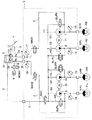
本発明の一実施形態を適用した車両用ブレーキ制御装置の油圧回路構成を図1に示す。また、図2に、本実施形態の車両用ブレーキ制御装置の制御系を司るブレーキECU100の信号の入出力の関係を示す。以下、これらの図を参照して、本実施形態の車両用ブレーキ制御装置の構成について説明する。ここでは右前輪−左後輪、左前輪−右後輪の各配管系統を備えるX配管の油圧回路を構成する車両に本実施形態の車両用ブレーキ制御装置を適用した例について説明する。
(First embodiment)
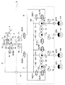
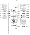
FIG. 1 shows a hydraulic circuit configuration of a vehicle brake control device to which an embodiment of the present invention is applied. FIG. 2 shows the input / output relationship of signals of the
図1に示されるように、車両用ブレーキ制御装置には、上述したブレーキECU100(図2参照)に加えて、ブレーキペダル1、踏力センサ2、マスタシリンダ(以下、M/Cという)3、ストローク制御弁SCSS、ストロークシミュレータ4、ブレーキ液圧制御用アクチュエータ5、ホイールシリンダ(以下、W/Cという)6FL、6FR、6RL、6RRが備えられている。
As shown in FIG. 1, in addition to the brake ECU 100 (see FIG. 2) described above, the vehicle brake control device includes a
ドライバによってブレーキ操作部材に相当するブレーキペダル1が踏み込まれると、ブレーキペダル1に加えられる踏力が踏力センサ2に入力され、踏力センサ2から加えられた踏力に応じた検出信号が出力されるように構成されている。この検出信号はブレーキECU100に入力され、ブレーキECU100でブレーキペダル1に加えられた踏力が検出される。なお、ここではブレーキ操作部材の操作量を検出するための操作量センサとして踏力センサ2を例に挙げているが、ストロークセンサ等であっても良い。また、ストロークセンサの検出信号や後述するM/C圧を検出するための圧力センサ17、18の検出信号に基づいてドライバによるブレーキペダル1の操作状態を検出できるようにしても構わない。
When the driver depresses the
ブレーキペダル1には、加えられた踏力をM/C3に伝達するプッシュロッド等が接続されており、このプッシュロッド等が押されることでM/C3に備えられるプライマリ室3aおよびセカンダリ室3bにM/C圧が発生させられるようになっている。
The
M/C3には、プライマリ室3aとセカンダリ室3bを構成するプライマリピストン3cおよびセカンダリピストン3dが備えられ、これらがスプリング3eの弾性力を受けることで、ブレーキペダル1が踏み込まれていないときには各ピストン3c、3dを押してブレーキペダル1を初期位置側に戻すように構成されている。
The M /
M/C3のプライマリ室3aとセカンダリ室3bからそれぞれブレーキ液圧制御用アクチュエータ5に伸びる管路A、Bが備えられている。
Pipe lines A and B extending from the
また、M/C3には、マスタリザーバ3fが備えられている。マスタリザーバ3fは、ブレーキペダル1が初期位置のときに、プライマリ室3aおよびセカンダリ室3bのそれぞれと図示しない通路を介して接続されるもので、M/C3内にブレーキ液を供給したり、M/C3内の余剰ブレーキ液を貯留する。
The M /
このマスタリザーバ3fからは、ブレーキ液圧制御用アクチュエータ5に向けて直接管路Cが延設されている。
A pipe C is directly extended from the
ストロークシミュレータ4は、管路Bに繋がる管路Dに接続されており、セカンダリ室3b内のブレーキ液を収容する役割を果たす。管路Dには、管路Dの連通・遮断状態を制御できる常閉型の二位置弁により構成されたストローク制御弁SCSSが備えられ、このストローク制御弁SCSSにより、ストロークシミュレータ4へのブレーキ液の流動が制御できるように構成されている。
The
ブレーキ液圧制御用アクチュエータ5は、以下のように構成されている。
The brake fluid
M/C3のプライマリ室3aと前輪FRに対応するW/C(前輪用第1W/C)6FRを接続するように、管路Aに繋げられる管路Eが備えられている。この管路Eには、第1常開弁SNO1が備えられている。第1常開弁SNO1は、非通電時には連通状態、通電時には遮断状態となる二位置弁であり、この第1常開弁SNO1によって管路Eの連通・遮断状態が制御される。
A pipe E connected to the pipe A is provided so as to connect the
また、M/C3のセカンダリ室3bと前輪FLに対応するW/C(前輪用第2W/C)6FLを接続するように、管路Bが繋げられる管路Fが備えられている。この管路Fには、第2常開弁SNO2が備えられている。第2常開弁SNO2は、非通電時には連通状態、通電時には遮断状態となる二位置弁であり、この第2常開弁SNO2によって管路Fの連通・遮断状態が制御される。
Further, a pipe line F to which the pipe line B is connected is provided so as to connect the
また、マスタリザーバ3fから延設された管路Cが接続される管路Gが設けられている。この管路Gは、管路G1、G2、G3、G4という4本の管路に分岐して、上述した前輪FL、FRに対応するW/C6FL、6FR、および、後輪RL、RRに対応するW/C(後輪用第1、第2W/C)6RL、6RRに接続される。
Further, a pipe line G to which a pipe line C extending from the
各管路G1〜G4には、それぞれ1つずつポンプ(第1〜第4ポンプ)7、8、9、10が備えられている。各ポンプ7〜10は、例えば静寂性に有効なトロコイドポンプにより構成されている。ポンプ7〜10のうち、ポンプ7、8は、第1モータ11によって駆動され、ポンプ9、10は、第2モータ12によって駆動される。第1、第2モータ11、12としてどのようなモータを用いても良いが、立上りが早いブラシレスモータを用いると好ましい。
Each of the pipelines G1 to G4 is provided with one pump (first to fourth pump) 7, 8, 9, and 10, respectively. Each pump 7-10 is comprised, for example by the trochoid pump effective for silence. Among the
また、ポンプ7〜10のそれぞれには、並列的に調圧回路を構成する管路H1、H2、H3、H4が備えられている。
In addition, each of the
ポンプ7に対して並列的に接続された管路H1には、直列的に接続された第1常閉弁SWC1と第1リニア弁SLFRが備えられ、第1常閉弁SWC1がポンプ7の吸入ポート側(上流側)に第1リニア弁SLFRが吐出ポート側(下流側)に位置するように配置されている。つまり、第1常閉弁SWC1により、管路H1を通じてマスタリザーバ3f側へのブレーキ液の返流を制御できる構成とされている。
The pipe H1 connected in parallel to the
ポンプ8に対して並列的に接続された管路H2には、第2リニア弁SLRLが備えられている。
A pipe H2 connected in parallel to the
ポンプ9に対して並列的に接続された管路H3には、直列的に接続された第2常閉弁SWC2と第3リニア弁SLFLが備えられ、第2常閉弁SWC2がポンプ9の吸入ポート側(上流側)に第3リニア弁SLFLが吐出ポート側(下流側)に位置するように配置されるている。つまり、第2常閉弁SWC2により、管路H3を通じてマスタリザーバ3f側へのブレーキ液の返流を制御できる構成とされている。
The pipe H3 connected in parallel to the
ポンプ10に対して並列的に接続された管路H4には、第4リニア弁SLRRが備えられている。
A pipe H4 connected in parallel to the
そして、管路G1〜G4のうち、各ポンプ7〜10と各W/C6FR〜6RRの間に圧力センサ(第1〜第4圧力センサ)13、14、15、16が配置されることで、各W/C圧が検出できるように構成されていると共に、管路E、Fのうち第1、第2常開弁SNO1、SNO2よりも上流側(M/C3側)にも圧力センサ17、18が配置されることで、M/C3のプライマリ室3aとセカンダリ室3bに発生しているM/C圧を検出できるように構成されている。
And among the pipe lines G1-G4, pressure sensors (first to fourth pressure sensors) 13, 14, 15, 16 are disposed between the pumps 7-10 and the W / C 6FR-6RR, Each W / C pressure is configured to be detected, and the
さらに、前輪FRに対するW/C6FRを加圧するためのポンプ7の吐出ポートおよび前輪FLに対するW/C6FLを加圧するためのポンプ9の吐出ポートには、それぞれ、逆止弁20、21が備えられている。これら逆止弁20、21は、W/C6FR、6FL側からポンプ7、9側へのブレーキ液の流動を禁止するために備えられている。このような構造により、ブレーキ液圧制御用アクチュエータ5が構成されている。
Further, the discharge port of the
このような車両用ブレーキ制御装置では、上述した管路A、管路Eを通じてプライマリ室3aとW/C6FRを繋ぐ油圧回路(第1補助管路)と、管路C、管路G、G1、G2を通じてマスタリザーバ3fとW/C6FR、6RLを繋ぐ油圧回路(主管路)、および、ポンプ7、8に並列的に接続された管路H1、H2の油圧回路(第1、第2調圧回路)が第1配管系統を構成するものとなる。
In such a vehicle brake control device, a hydraulic circuit (first auxiliary pipeline) connecting the
また、管路B、管路Fを通じてセカンダリ室3bとW/C6FRを繋ぐ油圧回路(第2補助管路)と、管路C、管路G、G3、G4を通じてマスタリザーバ3fとW/C6FL、6RRを繋ぐ油圧回路(主管路)、および、ポンプ9、10に並列的に接続された管路H3、H4の油圧回路(第3、第4調圧回路)が第2配管系統を構成するものとなる。
Also, a hydraulic circuit (second auxiliary pipeline) connecting the
そして、図2に示されるように、上記した踏力センサ2や各圧力センサ13〜18の検出信号がブレーキECU100に入力される。
Then, as shown in FIG. 2, detection signals from the
ブレーキECU100は、CPU、ROM、RAM、I/O等を備えた周知のマイクロコンピュータによって構成され、ROMなどに記憶されたプログラムに従って各種処理を実行する。このブレーキECU100には、例えば、各種制御弁SCSS、SNO1、SNO2、SWC1、SWC2、SLFR、SLRL、SLFL、SLRRや第1、第2モータ11、12への電力供給ラインのON/OFFを制御する半導体スイッチング素子(図示せず)が備えられており、この半導体スイッチング素子のON/OFFを制御すること等により、電力供給のON/OFFや単位時間当たりに供給する電流値(つまり消費電力量)を制御できるようになっている。
The
具体的には、ブレーキECU100は、目標W/C圧演算部100a、目標W/C圧変化勾配演算部100b、モータ出力演算部100cおよびモータ出力調整部100d等を有して構成されている。
Specifically, the
目標W/C圧演算部100aは、目標制動力を発生させるために必要となる目標W/C圧の演算を行うものである。具体的には、目標W/C圧演算部100aは、踏力センサ2の検出信号からブレーキ操作量に相当する踏力の物理値を求めたのち、それに相応した目標W/C圧を求める。このブレーキペダル1の操作量に対する目標W/C圧は、例えば単純な比例関係として示され、予め記憶しておいたブレーキペダル1の操作量−目標W/C圧の関係式もしくは関係を示すマップに基づいて求められる。
The target W / C
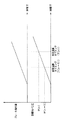
目標W/C圧変化勾配演算部100bは、目標W/C圧演算部100aの演算結果に基づいて目標W/C圧変化勾配を演算するものである。図3は、ブレーキ操作量に対する目標W/C圧と、その変化勾配の求め方を模式的に示した図である。この図に示すように、目標W/C圧変化勾配演算部100bは、目標W/C圧演算部100aで演算周期毎に目標W/Cが求められているため、前回の演算タイミングT(n−1)で演算された目標W/C圧P(n−1)と今回の演算タイミングT(n)で演算された目標W/C圧P(n)の差分ΔPを求め、その差分ΔPを演算間隔ΔT(=T(n)−T(n−1))で割った値(ΔP/ΔTを目標W/C圧変化勾配としている。
The target W / C pressure change
モータ出力演算部100cは、目標W/C圧演算部100aで求められた目標W/C圧に基づいて第1、第2モータ11、12への通電のデューティ比(以下、モータ出力デューティという)を求めると共に、目標W/C圧変化勾配演算部100bで求められた目標W/C圧変化勾配に基づいてモータ出力デューティを求め、前者を第1モータ出力デューティ、後者を第2モータ出力デューティとして、これらから実際に出力するモータ出力デューティを求めるものである。
The motor
具体的には、モータ出力演算部100cは、第1、第2モータ出力デューティを以下のように求めている。
Specifically, the motor
(1)第1モータ出力デューティについて
第1、第2モータ11、12を安定して回転させられる回転数、言い換えると第1〜第4リニア弁SLFR、SLRL、SLFL、SLRRでの調圧作用が安定して行える回転数(以下、モータ安定回転数という)は、第1、第2モータ11、12の特性などによって決まっている。そして、このモータ安定回転数を得るために必要な第1モータ出力デューティは、第1、第2モータ11、12のトルクに応じて変化する。
(1) About the first motor output duty The number of rotations at which the first and
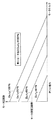
図4は、第1、第2モータ11、12のモータトルク−モータ回転数特性図である。この図に示されるように、モータトルク−モータ回転数特性は、第1モータ出力デューティに応じて変わっている。このため、第1、第2モータ11、12のトルクに応じて、モータ安定回転数を得るために必要とされる第1モータ出力デューティが異なったものとなる。例えば、現在のモータトルクが図4中に示す値であった場合には、モータ安定回転数を得るために必要なデューティ比は60%となる。
FIG. 4 is a motor torque-motor rotational speed characteristic diagram of the first and
そして、第1、第2モータ11、12のトルクは、各W/C6FR〜6RRに発生させるW/C圧と対応するものであるため、目標W/C圧演算部100aで今回の演算タイミングT(n)の目標W/C圧P(n)が求められると、それに基づいて対応するモータトルクが求められる。したがって、目標W/C圧演算部100aで求めた目標W/C圧に基づいて、モータ安定回転数を得るために必要な第1モータ出力デューティを求めることができる。
Since the torques of the first and
(2)第2モータ出力デューティについて
図5は、目標W/C圧とその目標W/C圧を発生させるために必要となるブレーキ液量の関係を示した特性図である。この図に示されるように、目標W/C圧を発生させるために必要となるブレーキ液量が決まっているため、目標W/C圧変化勾配演算部100bで記憶した前回の演算タイミング(n−1)で演算された目標W/C圧P(n−1)および今回の演算タイミングT(n)で演算された目標W/C圧P(n)と対応するブレーキ液量V(n−1)、V(n)を図5から求める。そして、それぞれに対応するブレーキ液量V(n−1)、V(n)の差分ΔVを演算間隔ΔTで割った値ΔV/ΔT[cc/s]として、目標W/C圧変化勾配ΔP/ΔTを達成するために必要なポンプ吐出液量勾配Qtargetが求められる。
(2) Second Motor Output Duty FIG. 5 is a characteristic diagram showing the relationship between the target W / C pressure and the amount of brake fluid required to generate the target W / C pressure. As shown in this figure, since the amount of brake fluid required to generate the target W / C pressure is determined, the previous calculation timing (n− stored in the target W / C pressure change
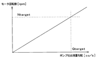
さらに、第1、第2モータ11、12の1回転当たりの第1〜第4ポンプ7〜9でのブレーキ液吐出量をVpumpとすると、第1、第2モータ11、12に必要な回転数Ntargetは、次式により求められ、図6のようにる。
Furthermore, if the brake fluid discharge amount in the first to
(数1)
Ntarget=Qtarget×60/Vpump[rpm]
この回転数Ntargetが、目標W/C圧変化勾配演算部100bで演算された目標W/C圧変化勾配ΔP/ΔTを達成するために必要なモータ回転数となる。そして、この回転数Ntargetを達成するために必要な第2モータ出力デューティは、図7に示すモータトルク−モータ回転数の特性図を利用して、目標W/C圧演算部100aにて今回の演算タイミングT(n)で求めた目標W/C圧P(n)に相当するトルクと回転数Ntargetの交差する点が属する特性線として求められる。
(Equation 1)
Ntarget = Qtarget × 60 / Vpump [rpm]
The rotational speed Ntarget is the motor rotational speed necessary to achieve the target W / C pressure change gradient ΔP / ΔT calculated by the target W / C pressure change
このように求められる第1モータ出力デューティと第2モータ出力デューティは、それぞれ、モータ安定回転数を得るために必要なものと、目標W/C圧変化勾配ΔP/ΔTを達成するために必要なものである。このため、これらのうちのいずれか大きい方を実際に出力するモータ出力デューティとすれば、モータ安定回転数を得られ、かつ、目標W/C圧変化勾配ΔP/ΔTを達成することが可能となる。 The first motor output duty and the second motor output duty thus obtained are respectively necessary for obtaining the stable motor rotation speed and for achieving the target W / C pressure change gradient ΔP / ΔT. Is. Therefore, if the motor output duty that actually outputs the larger one of these is set as the motor output duty, it is possible to obtain the stable motor rotation speed and to achieve the target W / C pressure change gradient ΔP / ΔT. Become.
したがって、モータ出力演算部100cは、上記のようにして第1、第2モータ出力デューティを演算したのち、これらのうちのいずれか大きい方を実際に出力するモータ出力デューティとして選択する。
Therefore, after calculating the first and second motor output duties as described above, the motor
モータ出力調整部100dは、モータ出力演算部100cの演算結果に基づいて、第1、第2モータ11、12に対して流す電流の調整を行うものである。例えば、第1、第2モータ11、12への電力供給ラインに備えられる半導体スイッチング素子のON/OFFを制御することで、単位時間当たりに供給する電流値(つまり消費電力量)を制御し、第1、第2モータ11、12に演算された電流値の電流が供給されるようにする。
The motor
また、ブレーキECU100は、各部100a、100bでの演算結果に基づき、各種制御弁SCSS、SNO1、SNO2、SWC1、SWC2、SLFR、SLRL、SLFL、SLRRや第1、第2モータ11、12を駆動するための制御信号を出力することで、各W/C6FR〜6RRに対してW/C圧を発生させる。そして、ブレーキECU100は、各圧力センサ13〜18の検出信号からW/C圧およびM/C圧を求めることで、実際に発生させられている制動力(実制動力)をフィードバックし、目標制動力に近づけるようにする。
Further, the
なお、ブレーキECU100や各種制御弁SCSS、SNO1、SNO2、SWC1、SWC2、SLFR、SLRL、SLFL、SLRRや第1、第2モータ11、12を駆動するための制御信号の出力は、図示しない車載バッテリからの電力供給に基づいて行われる。
Note that the output of control signals for driving the
続いて、上記のように構成される車両用ブレーキ制御装置の動作について、通常ブレーキ時と車両用ブレーキ制御装置に異常が発生した場合(以下、異常時という)に分けて説明する。 Next, the operation of the vehicle brake control device configured as described above will be described separately for normal braking and when the vehicle brake control device has an abnormality (hereinafter referred to as an abnormality).
図8は、通常ブレーキ時と異常時の各部の駆動状態を示した模式図である。なお、異常が発生したか否かに関しては、従来より行われているイニシャルチェックなどに基づいてブレーキECU100で判定され、一旦異常が発生するとそれが解除されるまでは異常時のブレーキ動作が行われることになる。以下、この図を参照して通常ブレーキ時と異常時の動作について説明する。
FIG. 8 is a schematic diagram showing the driving state of each part during normal braking and during abnormal conditions. Whether or not an abnormality has occurred is determined by the
(1)通常ブレーキ時の動作
通常ブレーキ時には、ブレーキペダル1が踏み込まれて踏力センサ2の検出信号がブレーキECU100に入力されると、ブレーキECU100は、図8に示すような駆動形態となるように各種制御弁SCSS、SNO1、SNO2、SWC1、SWC2、SLFR、SLRL、SLFL、SLRRや第1、第2モータ11、12を駆動する。
(1) Operation during normal braking During normal braking, when the
具体的には、ブレーキECU100は、踏力センサ2の検出信号に基づいて、目標W/C圧演算部100aにて目標W/C圧の演算を行うと共に、目標W/C圧変化勾配演算部100bにて目標W/C圧変化勾配の演算を行う。そして、これらの演算結果に基づいて、モータ出力演算部100cにて、上述した手法によって第1モータ出力デューティと第2モータ出力デューティを求め、これらを大小比較して、いずれか大きい方を実際に出力するモータ出力デューティとして設定する。そして、モータ出力調整部100dにて、求められたモータ出力デューティに基づいて、例えば、第1、第2モータ11、12への電力供給ラインに備えられる半導体スイッチング素子のON/OFFを制御することで、単位時間当たりに供給する電流値を制御する。
Specifically, the
そして、第1、第2モータ11、12に対して電流が流されると、ポンプ7〜10によるブレーキ液の吸入・吐出が行われ、各W/C6FR〜6RRに対してブレーキ液が供給される。
When a current is supplied to the first and
また、第1、第2常開弁SNO1、SNO2への通電は共にONされ、第1、第2常閉弁SWC1、SWC2への通電も共にONされる。これにより、第1、第2常開弁SNO1、SNO2は共に遮断状態、第1、第2常閉弁SWC1、SWC2は共に連通状態とされる。 In addition, energization of the first and second normally open valves SNO1 and SNO2 is both turned on, and energization of the first and second normally closed valves SWC1 and SWC2 are both turned on. As a result, the first and second normally open valves SNO1, SNO2 are both shut off, and the first, second normally closed valves SWC1, SWC2 are both in communication.
第1〜第4リニア弁SLFR、SLRL、SLFL、SLRRは、通電のON/OFFがデューティ制御(もしくはPWM制御)されることで、単位時間当たりの通電量が調整され、上下流間に発生させる差圧量がリニアに制御される。ストローク制御弁SCSSに関しては、通電がONされる。このため、管路B、Dを通じて、ストロークシミュレータ4がセカンダリ室3bと連通状態となり、ブレーキペダル1が踏み込まれたときに、各ピストン3c、3dが移動しても、セカンダリ室3b内のブレーキ液がストロークシミュレータ4に移動することになる。したがって、ドライバがブレーキペダル1を踏み込んだときに踏み込みに応じた反力が得られ、かつ、M/C圧が高圧になり過ぎることでブレーキペダル1に対して硬い板を踏み込むような感覚(板感)が発生することなく、ブレーキペダル1が踏み込めるようになっている。
The first to fourth linear valves SLFR, SLRL, SLFL, SLRR are generated between upstream and downstream by adjusting the energization amount per unit time by ON / OFF of energization being duty controlled (or PWM control). The amount of differential pressure is controlled linearly. The stroke control valve SCSS is energized. For this reason, even if each
このとき、第1、第2常開弁SNO1、SNO2が遮断状態とされているため、ポンプ7〜10によるブレーキ液吐出により、ポンプ7〜10の下流側のブレーキ液圧、つまり各W/C6FR〜6RRのW/C圧が増加させられることになる。 At this time, since the first and second normally open valves SNO1, SNO2 are shut off, the brake fluid discharge by the pumps 7-10 causes the brake fluid pressure downstream of the pumps 7-10, that is, each W / C6FR. The W / C pressure of ~ 6RR will be increased.
また、第1、第2常閉弁SWC1、SWC2が連通状態とされ、かつ、第1〜第4リニア弁SLFR、SLRL、SLFL、SLRRへの単位時間当たりの通電量がデューティ制御されているため、デューティ比に応じて各W/C6FR〜6RRのW/C圧が調整される。 In addition, the first and second normally closed valves SWC1 and SWC2 are in communication, and the energization amount per unit time to the first to fourth linear valves SLFR, SLRL, SLFL, SLRR is duty controlled. The W / C pressure of each W / C 6FR to 6RR is adjusted according to the duty ratio.
そして、ブレーキECU100にて、各圧力センサ13〜16の検出信号に基づいて各車輪FR〜RRのW/C6FR〜6RRに発生しているW/C圧をモニタリングし、第1、第2モータ11、12の通電量を調整することで第1、第2モータ11、12の回転数を制御すると共に、第1〜第4リニア弁SLFR、SLRL、SLFL、SLRRへの通電のON/OFFのデューティ比を制御することで、各W/C圧が所望の値となるようにする。
The
これにより、ブレーキペダル1に加えられた踏力に応じた目標制動力となるように、制動力が発生させられることになる。
As a result, the braking force is generated so that the target braking force corresponding to the pedaling force applied to the
(2)異常時のブレーキ動作
異常時には、ブレーキECU100から制御信号が出力できなくなるか、もしくは、各種制御弁SCSS、SNO1、SNO2、SWC1、SWC2、SLFR、SLRL、SLFL、SLRRや第1、第2モータ11、12が正常に駆動されない可能性がある。このため、各種制御弁SCSS、SNO1、SNO2、SWC1、SWC2、SLFR、SLRL、SLFL、SLRRや第1、第2モータ11、12すべてに関して、図8に示されるように通電がOFFされる。
(2) Brake operation at the time of abnormality When an abnormality occurs, a control signal cannot be output from the
すなわち、第1、第2常開弁SNO1、SNO2への通電が共にOFFとなるため、これらは共に連通状態となる。第1、第2常閉弁SWC1、SWC2への通電も共にOFFとなるため、これらは共に遮断状態とされる。 That is, since the energization to both the first and second normally open valves SNO1, SNO2 is turned off, both are in a communication state. Since the energization of the first and second normally closed valves SWC1 and SWC2 is also turned off, both are cut off.
また、第1〜第4リニア弁SLFR、SLRL、SLFL、SLRRも、すべて通電がOFFとなるため、すべて連通状態となる。ストローク制御弁SCSSも通電がOFFとなるため、ストロークシミュレータ4とセカンダリ室3bの間が遮断状態となる。
In addition, all of the first to fourth linear valves SLFR, SLRL, SLFL, and SLRR are in the communication state because the energization is turned off. Since the energization of the stroke control valve SCSS is also turned off, the
さらに、第1、第2モータ11、12への通電が共にOFFとなり、ポンプ7〜10によるブレーキ液の吸入・吐出も停止される。
Further, the energization of the first and
このような状態になると、M/C3におけるプライマリ室3aは、管路A、E、G1を介して右前輪FRにおけるW/C6FRとつながった状態となり、セカンダリ室3bは、管路B、F、G3を通じて左前輪FLにおけるW/C6FLとつながった状態となる。
In this state, the
このため、ブレーキペダル1が踏み込まれ、加えられた踏力に応じてプッシュロッド等が押されることで、M/C3におけるプライマリ室3aおよびセカンダリ室3bにM/C圧が発生させられると、それが両前輪FL、FRのW/C6FL、6FRに伝えられる。これにより、両前輪FL、FRに対して制動力が発生させられることになる。
For this reason, when the
なお、このような異常時の作動において、前輪側の各W/C6FR、6FLのW/C圧が管路G1、G3に発生することになるが、逆止弁20、21を備えているため、このW/C圧がポンプ7、9に加わることによってポンプ7、9でのブレーキ液漏れが発生し、W/C圧が低下してしまうことを防ぐことが可能となる。
In such an abnormal operation, the W / C pressures of the W / C 6FR and 6FL on the front wheel side are generated in the pipelines G1 and G3, but the
以上説明したように、本実施形態の車両用ブレーキ制御装置によれば、モータ安定回転数を得るために必要となる第1モータ出力デューティと、目標W/C圧変化勾配ΔP/ΔTを達成するために必要な第2モータ出力デューティを求め、これらのうちのいずれか大きい方を実際に出力するモータ出力デューティとしている。 As described above, according to the vehicle brake control device of the present embodiment, the first motor output duty and the target W / C pressure change gradient ΔP / ΔT necessary to obtain the motor stable rotational speed are achieved. The second motor output duty necessary for this purpose is obtained, and the larger one of these is set as the motor output duty that is actually output.
これにより、モータ安定回転数を得られ、かつ、目標W/C圧変化勾配ΔP/ΔTを達成することが可能となるため、モータの消費電力量を小さくしつつ、かつ、ドライバの制動要求に対する応答性を高めることができる。 As a result, it is possible to obtain a stable motor rotation speed and to achieve the target W / C pressure change gradient ΔP / ΔT, so that the power consumption of the motor is reduced and the driver's braking request is met. Responsiveness can be improved.
(第2実施形態)
本発明の第2実施形態について説明する。本実施形態は、第1実施形態に対して車両用ブレーキ制御装置の構成を一部変更したものであり、基本的には第1実施形態と同様の構成となっているため、第1実施形態と異なる部分についてのみ説明する。
(Second Embodiment)
A second embodiment of the present invention will be described. The present embodiment is obtained by partially changing the configuration of the vehicle brake control device with respect to the first embodiment, and basically has the same configuration as the first embodiment. Only different parts will be described.
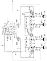
図9は、本実施形態の車両用ブレーキ制御装置の油圧回路構成を示したものである。この図に示されるように、本実施形態の車両用ブレーキ制御装置では、管路Gが2つの管路Ga、Gbに分岐されており、管路Ga(つまり、分岐点よりも下流かつ管路H1、H2の上流側)に第1常閉弁SWC1が備えられ、管路Gb(つまり、分岐点よりも下流かつ管路H3、H4の上流側)に第2常閉弁SWC2が備えられた構成としてある。 FIG. 9 shows a hydraulic circuit configuration of the vehicle brake control device of the present embodiment. As shown in this figure, in the vehicle brake control device of the present embodiment, the pipeline G is branched into two pipelines Ga and Gb, and the pipeline Ga (that is, downstream of the branch point and the pipeline) A first normally closed valve SWC1 is provided on the upstream side of H1 and H2, and a second normally closed valve SWC2 is provided on the pipeline Gb (that is, downstream of the branch point and upstream of the pipelines H3 and H4). As a configuration.
このような構成においても、モータ安定回転数を得るために必要となる第1モータ出力デューティと、目標W/C圧変化勾配ΔP/ΔTを達成するために必要な第2モータ出力デューティを求め、これらのうちのいずれか大きい方を実際に出力するモータ出力デューティとすることで、第1実施形態と同様の効果を得ることができる。 Even in such a configuration, the first motor output duty necessary for obtaining the motor stable rotational speed and the second motor output duty necessary for achieving the target W / C pressure change gradient ΔP / ΔT are obtained, By setting the larger one of these as the motor output duty that is actually output, the same effect as in the first embodiment can be obtained.
また、このような構成によれば、異常時に第1常閉弁SWC1が遮断状態となっても、管路H1、H2の上流側が遮断状態となるだけであるため、ブレーキペダル1の踏み込みによってM/C3のプライマリ室3aにM/C圧が発生させられると、それが右前輪FRのW/C6FRだけでなく左後輪RLのW/C6RLにも伝えられるようにできる。同様に、異常時に第2常閉弁SWC2が遮断状態となっても、管路H3、H4の上流側が遮断状態となるだけであるため、ブレーキペダル1の踏み込みによってM/C3のセカンダリ室3bにM/C圧が発生させられると、それが左前輪FLのW/C6FLだけでなく右後輪RRのW/C6RRにも伝えられるようにできる。
Further, according to such a configuration, even when the first normally closed valve SWC1 is shut off at the time of abnormality, only the upstream side of the pipelines H1 and H2 is shut off. When the M / C pressure is generated in the
このように、本実施形態の車両用ブレーキ制御装置によれば、異常時に4輪FR〜RRのすべてについて、W/C6FR〜6RRにW/C圧を発生させることが可能となる。これにより、よりバランス良い制動力を発生させることができる。
Thus, according to the vehicle brake control device of the present embodiment, it is possible to generate W / C pressures in W /
なお、本実施形態では、第1実施形態に示した逆止弁20、21を設けていないが、仮にポンプ7、9からブレーキ液漏れが発生したとしても、各ポンプ7、9の上流に位置する第1、第2常閉弁SWC1、SWC2によってブレーキ液が止められることになるため、W/C圧の低下は起こらない。
In this embodiment, the
(第3実施形態)
本発明の第3実施形態について説明する。本実施形態は、第2実施形態に対して車両用ブレーキ制御装置の構成を一部変更したものであり、基本的には第2実施形態と同様の構成となっているため、第2実施形態と異なる部分についてのみ説明する。
(Third embodiment)
A third embodiment of the present invention will be described. In the present embodiment, the configuration of the vehicle brake control device is partly changed with respect to the second embodiment, and basically has the same configuration as the second embodiment. Only different parts will be described.
図10は、本実施形態の車両用ブレーキ制御装置の油圧回路構成を示したものである。この図に示すように、本実施形態の車両用ブレーキ制御装置は、第1、第2実施形態のように第1、第2常閉弁SWC1、SWC2の2つを備えた構造ではなく、1つの常閉弁SWCのみを2つの配管系統の双方で共用した構造としている。 FIG. 10 shows a hydraulic circuit configuration of the vehicle brake control device of the present embodiment. As shown in this figure, the vehicle brake control device of this embodiment is not a structure having two first and second normally closed valves SWC1, SWC2 as in the first and second embodiments. Only one normally closed valve SWC is shared by the two piping systems.
このような構成においても、モータ安定回転数を得るために必要となる第1モータ出力デューティと、目標W/C圧変化勾配ΔP/ΔTを達成するために必要な第2モータ出力デューティを求め、これらのうちのいずれか大きい方を実際に出力するモータ出力デューティとすることで、第1実施形態と同様の効果を得ることができる。 Even in such a configuration, the first motor output duty necessary for obtaining the motor stable rotational speed and the second motor output duty necessary for achieving the target W / C pressure change gradient ΔP / ΔT are obtained, By setting the larger one of these as the motor output duty that is actually output, the same effect as in the first embodiment can be obtained.
また、このような構成としても、通常ブレーキ時には、4輪FR〜RRのW/C6FR〜6RRのW/C圧を適宜調圧でき、異常時には、4輪FR〜RRのW/C6FR〜6RRに対してブレーキペダル1の踏み込みに応じてM/C3に発生したM/C圧を伝えることが可能となる。
Also, with such a configuration, the W / C pressure of the W / C6FR to 6RR of the four wheels FR to RR can be adjusted as appropriate during normal braking, and the W / C6FR to 6RR of the four wheels FR to RR can be adjusted when abnormal. On the other hand, it is possible to transmit the M / C pressure generated in the M /
さらに、本実施形態では、異常時に、1つの常閉弁SWCにより、2つの配管系統のすべての車輪FR〜RRに対してM/C圧を伝えることが可能となるため、システムをコンパクトな構成とすることが可能となる。 Furthermore, in this embodiment, since it becomes possible to transmit the M / C pressure to all the wheels FR to RR of the two piping systems by one normally closed valve SWC at the time of abnormality, the system has a compact configuration. It becomes possible.
なお、本実施形態の車両用ブレーキ制御装置において、常閉弁SWCの駆動形態は、図8に示した第1実施形態の車両用ブレーキ制御装置における第1、第2常閉弁SWC1、SWC2と同様である。 In the vehicle brake control device of this embodiment, the drive mode of the normally closed valve SWC is the same as the first and second normally closed valves SWC1 and SWC2 in the vehicle brake control device of the first embodiment shown in FIG. It is the same.
(他の実施形態)
図1に示した車両用ブレーキ制御装置は、本発明を適用できるブレーキ構成例として示したものであり、図1に示したものに限定されるものではなく、様々な形態で変更可能である。
(Other embodiments)
The vehicle brake control device shown in FIG. 1 is shown as an example of a brake configuration to which the present invention can be applied, and is not limited to that shown in FIG. 1 and can be modified in various forms.
また、第1実施形態では、右前輪−左後輪、左前輪−右後輪の各配管系統を備えるX配管の油圧回路を構成する車両に本実施形態の車両用ブレーキ制御装置を適用した例について説明したが、前後配管など他の系統にも本発明を適用可能である。 Further, in the first embodiment, an example in which the vehicle brake control device of the present embodiment is applied to a vehicle that configures an X piping hydraulic circuit including piping systems of a right front wheel—left rear wheel and a left front wheel—right rear wheel. However, the present invention is also applicable to other systems such as front and rear piping.
また、上記各実施形態では、マスタリザーバ3fに繋がるのが管路Cの一本のみで、この管路Cを通じて第1、第2配管系統の双方へのブレーキ液の供給が行われるようにした。しかしながら、管路Cの他にもう一本備え、例えば管路Cにて第1配管系統へのブレーキ液の供給を行い、もう一本の管路にて第2配管系統へのブレーキ液の供給を行うようにしても良い。
In each of the above embodiments, only one pipe C is connected to the
また、上記各実施形態では、第1〜第4ポンプ7〜10による加圧が行えない異常時を考慮して、M/C3と第1、第2配管系統を接続した構成とし、通常ブレーキ時にはマスタリザーバ3fからブレーキ液が供給されるようにしている。しかしながら、これも単なる一例であり、M/C3と第1、第2配管系統が接続される形態でなくても良いし、M/C3自体が無いようなブレーキ構成であっても構わない。また、ブレーキ液の供給もマスタリザーバ3fからでなく、ブレーキ液を貯留できる他のリザーバから行われるようにしても良い。
Moreover, in each said embodiment, it considered as the structure which connected M / C3 and the 1st, 2nd piping system in consideration of the time of the abnormality which cannot pressurize with the 1st-4th pumps 7-10, and at the time of a normal brake Brake fluid is supplied from the
さらに、上記実施形態では、フェールセーフを考慮して、第1〜第4リニア弁SLFR〜SLRRを駆動しなくてもブレーキペダル1の踏み込みに基づいて発生させられたM/C圧がW/C6FL、6FR等に伝えられるようにしている。しかしながら、異常が発生した場所が第1〜第4リニア弁SLFR〜SLRR以外の部位であれば、これらを駆動することができるため、これらに通電を行い管路H1〜H4を遮断状態(もしくは上下流間に最大差圧が発生させられる状態)にできるようにすれば、上記と同様にM/C圧をW/C6FL、6FR等に伝えることが可能となる。このため、必ずしも第1、第2常閉弁SWC1、SWC2および常閉弁SWCを備えなければならない訳ではなく、図11に示す油圧回路構成に示されるように、第1、第2常閉弁SWC1、SWC2および常閉弁SWCを備えない構造であっても構わない。
Further, in the above embodiment, in consideration of fail-safety, the M / C pressure generated based on the depression of the
ただし、すべて機械的にフェールセーフが行えるようにするという意味では、第1、第2常閉弁SWC1、SWC2および常閉弁SWCが重要となる。 However, the first and second normally closed valves SWC1, SWC2 and the normally closed valve SWC are important in the sense that all can be made fail safe mechanically.
このため、図12に示す油圧回路構成のように、第1リニア弁SLFRと第3リニア弁SLFLを常閉型のリニア弁として構成しておけば、機械的にフェールセーフを行うことも可能となるため、より好ましい構造となる。勿論、第2、第4リニア弁SLRL、SLRRに関しても、常閉型のリニア弁としても構わない。 For this reason, if the first linear valve SLFR and the third linear valve SLFL are configured as normally closed linear valves as in the hydraulic circuit configuration shown in FIG. 12, it is possible to perform fail-safe mechanically. Therefore, a more preferable structure is obtained. Of course, the second and fourth linear valves SLRL and SLRR may be normally closed linear valves.
なお、ブレーキ操作部材としてブレーキペダル1を例に挙げたが、ブレーキレバーなどであっても構わない。
In addition, although the
1…ブレーキペダル、2…踏力センサ、3…M/C、3f…マスタリザーバ、4…ストロークシミュレータ、5…ブレーキ液圧制御用アクチュエータ、6FL、6FR、6RL、6RR…W/C、7〜10…ポンプ、11、12…モータ、13〜18…圧力センサ、100…ブレーキECU、100a…目標W/C圧演算部、100b…目標W/C圧変化勾配演算部、100c…モータ出力演算部、100d…モータ出力調整部、A〜F、G1〜G4、H1〜H4…管路、FL、FR、RL、RR…車輪、SCSS…ストローク制御弁、SLFL、SLFR、SLRR、SLRR…第1〜第4リニア弁、SNO1、SNO2…第1、第2常開弁、SWC…常閉弁、SWC1、SWC2…第1、第2常閉弁。
DESCRIPTION OF
Claims (3)
前記ブレーキ操作部材の操作量を検出する操作量センサ(2)と、
2つの前輪(FR、FL)それぞれに対応して設けられた前輪用第1、第2ホイールシリンダ(6FR、6FL)、および、2つの後輪(RL、RR)それぞれに対応して設けられた後輪用第1、第2ホイールシリンダ(6RL、6RR)と、
ブレーキ液を貯留しているリザーバ(3f)と、
前記リザーバと前記前輪用第1、第2および前記後輪用第1、第2ホイールシリンダをつなぎ、前記前輪用第1、第2および前記後輪用第1、第2ホイールシリンダそれぞれに接続されるように4つに分岐された主管路(C、G、G1〜G4)と、
前記主管路のうち4つに分岐された部位(G1〜G4)それぞれに対して1つずつ配置され、前記リザーバに貯留されたブレーキ液を吸入・吐出して、前記前輪用第1、第2および後輪用第1、第2ホイールシリンダそれぞれを加圧する第1〜第4ポンプ(7〜10)と、
前記第1、第2ポンプ(7、8)により加圧される系統を第1配管系統として、該第1配管系統に備えられた前記第1、第2ポンプを駆動するための第1モータ(11)と、
前記第3、第4ポンプ(9、10)により加圧される系統を第2配管系統として、該第2配管系統に備えられた前記第3、第4ポンプを駆動するための第2モータ(12)と、
前記第1〜第4ポンプに並列的に配置され、前記リザーバへブレーキ液を返流する管路となる第1〜第4調圧回路(H1〜H4)と、
前記第1〜第4調圧回路にそれぞれ対応して配置された第1〜第4リニア弁(SLFR、SLRL、SLFL、SLRR)と、
前記操作量センサの検出信号に基づいて、前記第1〜第4リニア弁および前記第1、第2モータを駆動し、前記第1、第2モータに流す電流値を前記操作量センサにて検出された操作量に対応する目標ホイールシリンダ圧に応じた値に可変させる制御手段(100)と、を備えた車両用ブレーキ制御装置であって、
前記制御手段は、
前記操作量センサに基づいて前記ブレーキ操作部材が操作されたことを検出したときに、前記操作量センサにて検出された操作量に対応する目標ホイールシリンダ圧(P(n))を求める目標ホイールシリンダ圧演算部(100a)と、
前記目標ホイールシリンダ圧の変化勾配(ΔP/ΔT)を演算する目標ホイールシリンダ圧変化勾配演算部(100b)と、
前記目標ホイールシリンダ圧に基づいて、前記第1〜第4リニア弁が安定して調圧作用を行えるモータ安定回転数を得るために必要な前記第1、第2モータに出力する電流のデューティ比となる第1モータ出力デューティを求めると共に、前記目標ホイールシリンダ圧変化勾配を達成するために必要な前記第1、第2モータに出力する電流のデューティ比となる第2モータ出力デューティを求め、前記第1、第2モータ出力デューティのうちの大きい方を実際に出力するモータ出力デューティとして設定するモータ出力演算部(100c)と、
前記モータ出力演算部にて設定された前記モータ出力デューティに基づいて、前記第1、第2モータに対して流す電流を調整するモータ出力調整部(100d)と、を備えていることを特徴とする車両用ブレーキ制御装置。 A brake operating member (1) operated by a driver;
An operation amount sensor (2) for detecting an operation amount of the brake operation member;
Front wheel first and second wheel cylinders (6FR, 6FL) provided corresponding to each of the two front wheels (FR, FL), and two rear wheels (RL, RR) provided respectively. Rear wheel first and second wheel cylinders (6RL, 6RR);
A reservoir (3f) storing brake fluid;
The reservoir is connected to the front wheel first, second, and rear wheel first and second wheel cylinders, and is connected to the front wheel first, second, and rear wheel first and second wheel cylinders, respectively. Main pipelines (C, G, G1 to G4) branched into four so that,
One for each of the four branches (G1 to G4) of the main pipeline (G1 to G4), and sucks and discharges the brake fluid stored in the reservoir. And first to fourth pumps (7 to 10) for pressurizing the first and second wheel cylinders for the rear wheels,
A system pressurized by the first and second pumps (7, 8) is defined as a first piping system, and a first motor for driving the first and second pumps provided in the first piping system ( 11) and
A system pressurized by the third and fourth pumps (9, 10) is used as a second piping system, and a second motor for driving the third and fourth pumps provided in the second piping system ( 12)
First to fourth pressure regulating circuits (H1 to H4) which are arranged in parallel to the first to fourth pumps and serve as conduits for returning the brake fluid to the reservoir;
First to fourth linear valves (SLFR, SLRL, SLFL, SLRR) arranged corresponding to the first to fourth pressure regulating circuits,
Based on a detection signal of the operation amount sensor, the first to fourth linear valves and the first and second motors are driven, and a current value flowing through the first and second motors is detected by the operation amount sensor. A vehicle brake control device comprising: control means (100) that varies the value according to the target wheel cylinder pressure corresponding to the operated amount;
The control means includes
A target wheel for obtaining a target wheel cylinder pressure (P (n)) corresponding to the operation amount detected by the operation amount sensor when it is detected that the brake operation member is operated based on the operation amount sensor. A cylinder pressure calculator (100a);
A target wheel cylinder pressure change gradient calculating unit (100b) for calculating a change gradient (ΔP / ΔT) of the target wheel cylinder pressure;
Based on the target wheel cylinder pressure, the duty ratio of the current output to the first and second motors necessary for obtaining a stable motor rotation speed at which the first to fourth linear valves can stably regulate pressure. And a second motor output duty that is a duty ratio of a current output to the first and second motors necessary to achieve the target wheel cylinder pressure change gradient. A motor output calculation unit (100c) that sets a larger one of the first and second motor output duties as a motor output duty to actually output;
A motor output adjustment unit (100d) for adjusting a current to be supplied to the first and second motors based on the motor output duty set by the motor output calculation unit; Brake control device for a vehicle.
前記モータ出力演算部は、前記目標ホイールシリンダ圧演算部で演算された前記目標ホイールシリンダ圧に基づいて、前回の演算タイミング(T(n−1))で演算された目標ホイールシリンダ圧(P(n−1))を発生させるために必要となるブレーキ液量(V(n−1))と今回の演算タイミング(T(n))で演算された前記目標ホイールシリンダ圧(P(n))を発生させるために必要となるブレーキ液量(V(n))の差分(ΔV)を前記演算周期における演算間隔(ΔT)で割った値(ΔV/ΔT)を必要なポンプ吐出液量勾配(Qtarget)として求めたのち、該ポンプ吐出液量勾配と前記第1、第2モータの1回転当たりの前記第1〜第4ポンプのブレーキ液吐出量(Vpump)に基づいて、前記目標ホイールシリンダ圧変化勾配を達成するために必要なモータ回転数を求め、さらに、前記今回の演算タイミングで演算された目標ホイールシリンダ圧に対応するモータトルクを求め、モータトルク−モータ回転数特性に基づき、前記モータトルクと前記目標ホイールシリンダ圧変化勾配を達成するために必要なモータ回転数に対応する電流のデューティ比を前記第2モータ出力デューティとすることを特徴とする請求項1または2に記載の車両用ブレーキ制御装置。
The target wheel cylinder pressure calculation unit obtains the target wheel cylinder pressure for each calculation cycle,
The motor output calculation unit is configured to calculate a target wheel cylinder pressure (P (P ()) calculated at a previous calculation timing (T (n-1)) based on the target wheel cylinder pressure calculated by the target wheel cylinder pressure calculation unit. n-1)) is required to generate the brake fluid amount (V (n-1)) and the target wheel cylinder pressure (P (n)) calculated at the current calculation timing (T (n)). The value (ΔV / ΔT) obtained by dividing the difference (ΔV) in the brake fluid amount (V (n)) required for generating the pressure by the calculation interval (ΔT) in the calculation cycle (ΔV / ΔT) Qtarget), and then, based on the pump discharge fluid amount gradient and the brake fluid discharge amount (Vpump) of the first to fourth pumps per one rotation of the first and second motors, the target wheel cylinder pressure Reaching the change gradient And a motor torque corresponding to the target wheel cylinder pressure calculated at the current calculation timing, and based on the motor torque-motor rotation speed characteristic, the motor torque and the target 3. The vehicle brake control device according to claim 1, wherein a duty ratio of a current corresponding to a motor rotational speed necessary to achieve a wheel cylinder pressure change gradient is set as the second motor output duty. 4.
Priority Applications (2)
| Application Number | Priority Date | Filing Date | Title |
|---|---|---|---|
| JP2006037993A JP4635896B2 (en) | 2006-02-15 | 2006-02-15 | Brake control device for vehicle |
| US11/702,502 US7621602B2 (en) | 2006-02-15 | 2007-02-06 | Vehicle brake control device |
Applications Claiming Priority (1)
| Application Number | Priority Date | Filing Date | Title |
|---|---|---|---|
| JP2006037993A JP4635896B2 (en) | 2006-02-15 | 2006-02-15 | Brake control device for vehicle |
Publications (2)
| Publication Number | Publication Date |
|---|---|
| JP2007216769A JP2007216769A (en) | 2007-08-30 |
| JP4635896B2 true JP4635896B2 (en) | 2011-02-23 |
Family
ID=38367638
Family Applications (1)
| Application Number | Title | Priority Date | Filing Date |
|---|---|---|---|
| JP2006037993A Expired - Fee Related JP4635896B2 (en) | 2006-02-15 | 2006-02-15 | Brake control device for vehicle |
Country Status (2)
| Country | Link |
|---|---|
| US (1) | US7621602B2 (en) |
| JP (1) | JP4635896B2 (en) |
Families Citing this family (10)
| Publication number | Priority date | Publication date | Assignee | Title |
|---|---|---|---|---|
| DE102004019511A1 (en) * | 2004-04-22 | 2005-11-10 | Zf Friedrichshafen Ag | Method for controlling a pressure medium pump in a motor vehicle |
| JP4839791B2 (en) * | 2005-11-18 | 2011-12-21 | 株式会社アドヴィックス | Brake control device for vehicle |
| JP4696950B2 (en) * | 2006-02-15 | 2011-06-08 | 株式会社アドヴィックス | Brake control device for vehicle |
| JP4835203B2 (en) * | 2006-03-01 | 2011-12-14 | 株式会社アドヴィックス | Brake control device for vehicle |
| JP4618169B2 (en) * | 2006-03-13 | 2011-01-26 | 株式会社アドヴィックス | Brake control device for vehicle |
| DE102011077313A1 (en) * | 2011-06-09 | 2012-12-13 | Continental Teves Ag & Co. Ohg | Method for operating a brake system and brake system |
| KR101265951B1 (en) * | 2011-06-28 | 2013-05-21 | 주식회사 만도 | Controlling Method of Electronic Parking Brake System |
| DE102013223861A1 (en) * | 2013-11-21 | 2015-05-21 | Continental Teves Ag & Co. Ohg | Brake system for motor vehicles |
| US10106137B2 (en) | 2017-01-06 | 2018-10-23 | Ford Global Technologies, Llc | Adjustment of maximum brake pump speed based on rate of change of target deceleration |
| US10300899B2 (en) * | 2017-01-06 | 2019-05-28 | Ford Global Technologies, Llc | Adjustment of maximum brake pump speed based on rate of change of target deceleration |
Family Cites Families (15)
| Publication number | Priority date | Publication date | Assignee | Title |
|---|---|---|---|---|
| JPH0880830A (en) * | 1994-09-09 | 1996-03-26 | Aisin Seiki Co Ltd | Anti-skid controller |
| US5487593A (en) * | 1994-11-23 | 1996-01-30 | Alliedsignal Inc. | Anti-lock braking system providing pump motor duty cycle based on deceleration and motor voltage feed back |
| JPH08142847A (en) * | 1994-11-24 | 1996-06-04 | Toyota Motor Corp | Brake system |
| JP3828609B2 (en) * | 1996-04-03 | 2006-10-04 | 本田技研工業株式会社 | Anti-lock brake device |
| JP3625115B2 (en) | 1997-01-22 | 2005-03-02 | 株式会社日立ユニシアオートモティブ | Braking device |
| US6113197A (en) * | 1996-11-18 | 2000-09-05 | Unisia Jecs Corporation | Wheel braking system |
| DE69918202T2 (en) * | 1998-02-20 | 2005-07-07 | Denso Corp., Kariya | Braking system for motor vehicles |
| JPH11301435A (en) * | 1998-02-20 | 1999-11-02 | Denso Corp | Brake device |
| GB2344142B (en) * | 1998-11-27 | 2003-01-22 | Lucas Ind Plc | Pump motor control in electro-hydraulic braking systems |
| JP2001071877A (en) * | 1999-09-09 | 2001-03-21 | Nissin Kogyo Co Ltd | Anti-lock brake control device for vehicles |
| US6291960B1 (en) * | 2000-03-22 | 2001-09-18 | Ford Global Technologies, Inc. | Pulse width modulated motor control system and method for reducing noise vibration and harshness |
| JP4276485B2 (en) * | 2003-08-18 | 2009-06-10 | 株式会社日立製作所 | Vehicle attitude control device |
| JP4839791B2 (en) * | 2005-11-18 | 2011-12-21 | 株式会社アドヴィックス | Brake control device for vehicle |
| JP4835203B2 (en) * | 2006-03-01 | 2011-12-14 | 株式会社アドヴィックス | Brake control device for vehicle |
| JP5119646B2 (en) * | 2006-03-06 | 2013-01-16 | 株式会社アドヴィックス | Brake control device for vehicle |
-
2006
- 2006-02-15 JP JP2006037993A patent/JP4635896B2/en not_active Expired - Fee Related
-
2007
- 2007-02-06 US US11/702,502 patent/US7621602B2/en not_active Expired - Fee Related
Also Published As
| Publication number | Publication date |
|---|---|
| US20070188015A1 (en) | 2007-08-16 |
| JP2007216769A (en) | 2007-08-30 |
| US7621602B2 (en) | 2009-11-24 |
Similar Documents
| Publication | Publication Date | Title |
|---|---|---|
| JP4839791B2 (en) | Brake control device for vehicle | |
| US7887145B2 (en) | Vehicle brake control device | |
| JP5119646B2 (en) | Brake control device for vehicle | |
| JP4661621B2 (en) | Brake control device for vehicle | |
| JP5969933B2 (en) | Brake device | |
| US7621602B2 (en) | Vehicle brake control device | |
| JP6748537B2 (en) | Electronic hydraulic brake device | |
| JP4618169B2 (en) | Brake control device for vehicle | |
| JP4696950B2 (en) | Brake control device for vehicle | |
| US8052226B2 (en) | Electronic control brake system having simulation function | |
| KR102530382B1 (en) | Electric brake system and control method thereof | |
| CN106232441A (en) | Brake control, brakes and brake fluid pressure production method | |
| US20180194332A1 (en) | Brake Control Apparatus and Brake System | |
| JP6245696B2 (en) | Brake fluid pressure generator | |
| JP2011051494A (en) | Brake control device | |
| JP2007216772A (en) | Brake control device for vehicle | |
| JP4696949B2 (en) | Brake control device for vehicle | |
| US20070208481A1 (en) | Vehicle brake control device | |
| JP2007216765A (en) | Braking force maintenance control device | |
| JP4816121B2 (en) | Brake control device for vehicle | |
| JP5565008B2 (en) | Braking control device | |
| JP2011100199A (en) | Current supply circuit and brake control device | |
| JP4760431B2 (en) | Brake control device for vehicle | |
| JP5977691B2 (en) | Brake control device | |
| JP2007216770A (en) | Brake control device for vehicle |
Legal Events
| Date | Code | Title | Description |
|---|---|---|---|
| A621 | Written request for application examination |
Free format text: JAPANESE INTERMEDIATE CODE: A621 Effective date: 20080806 |
|
| A977 | Report on retrieval |
Free format text: JAPANESE INTERMEDIATE CODE: A971007 Effective date: 20100915 |
|
| TRDD | Decision of grant or rejection written | ||
| A01 | Written decision to grant a patent or to grant a registration (utility model) |
Free format text: JAPANESE INTERMEDIATE CODE: A01 Effective date: 20101026 |
|
| A01 | Written decision to grant a patent or to grant a registration (utility model) |
Free format text: JAPANESE INTERMEDIATE CODE: A01 |
|
| A61 | First payment of annual fees (during grant procedure) |
Free format text: JAPANESE INTERMEDIATE CODE: A61 Effective date: 20101108 |
|
| FPAY | Renewal fee payment (event date is renewal date of database) |
Free format text: PAYMENT UNTIL: 20131203 Year of fee payment: 3 |
|
| R150 | Certificate of patent or registration of utility model |
Free format text: JAPANESE INTERMEDIATE CODE: R150 |
|
| LAPS | Cancellation because of no payment of annual fees |