JP4459776B2 - Heat pump device and outdoor unit of heat pump device - Google Patents
Heat pump device and outdoor unit of heat pump device Download PDFInfo
- Publication number
- JP4459776B2 JP4459776B2 JP2004303077A JP2004303077A JP4459776B2 JP 4459776 B2 JP4459776 B2 JP 4459776B2 JP 2004303077 A JP2004303077 A JP 2004303077A JP 2004303077 A JP2004303077 A JP 2004303077A JP 4459776 B2 JP4459776 B2 JP 4459776B2
- Authority
- JP
- Japan
- Prior art keywords
- refrigerant
- expansion valve
- heat exchanger
- compressor
- heat pump
- Prior art date
- Legal status (The legal status is an assumption and is not a legal conclusion. Google has not performed a legal analysis and makes no representation as to the accuracy of the status listed.)
- Active
Links
- 239000003507 refrigerant Substances 0.000 claims description 279
- 238000010438 heat treatment Methods 0.000 claims description 92
- 239000007788 liquid Substances 0.000 claims description 66
- 239000002826 coolant Substances 0.000 claims description 12
- XLYOFNOQVPJJNP-UHFFFAOYSA-N water Substances O XLYOFNOQVPJJNP-UHFFFAOYSA-N 0.000 claims description 5
- 238000005304 joining Methods 0.000 claims description 3
- 238000001514 detection method Methods 0.000 claims 2
- 238000007599 discharging Methods 0.000 claims 1
- 230000005855 radiation Effects 0.000 claims 1
- 238000002347 injection Methods 0.000 description 67
- 239000007924 injection Substances 0.000 description 67
- 230000007423 decrease Effects 0.000 description 27
- 238000001816 cooling Methods 0.000 description 23
- 238000005057 refrigeration Methods 0.000 description 17
- 230000000694 effects Effects 0.000 description 15
- 238000010257 thawing Methods 0.000 description 14
- 238000004378 air conditioning Methods 0.000 description 13
- 238000004781 supercooling Methods 0.000 description 12
- 238000000034 method Methods 0.000 description 11
- 238000010586 diagram Methods 0.000 description 9
- 238000007906 compression Methods 0.000 description 6
- 230000006835 compression Effects 0.000 description 5
- 230000003247 decreasing effect Effects 0.000 description 4
- 238000009826 distribution Methods 0.000 description 4
- 238000009833 condensation Methods 0.000 description 3
- 230000005494 condensation Effects 0.000 description 3
- 230000001276 controlling effect Effects 0.000 description 3
- 238000001704 evaporation Methods 0.000 description 2
- 238000009434 installation Methods 0.000 description 2
- 238000005259 measurement Methods 0.000 description 2
- 238000004904 shortening Methods 0.000 description 2
- 230000015572 biosynthetic process Effects 0.000 description 1
- 230000008020 evaporation Effects 0.000 description 1
- 238000000605 extraction Methods 0.000 description 1
- 238000002844 melting Methods 0.000 description 1
- 230000008018 melting Effects 0.000 description 1
- 230000001105 regulatory effect Effects 0.000 description 1
- 230000000630 rising effect Effects 0.000 description 1
- 238000011144 upstream manufacturing Methods 0.000 description 1
Images


Classifications
-
- F—MECHANICAL ENGINEERING; LIGHTING; HEATING; WEAPONS; BLASTING
- F25—REFRIGERATION OR COOLING; COMBINED HEATING AND REFRIGERATION SYSTEMS; HEAT PUMP SYSTEMS; MANUFACTURE OR STORAGE OF ICE; LIQUEFACTION SOLIDIFICATION OF GASES
- F25B—REFRIGERATION MACHINES, PLANTS OR SYSTEMS; COMBINED HEATING AND REFRIGERATION SYSTEMS; HEAT PUMP SYSTEMS
- F25B13/00—Compression machines, plants or systems, with reversible cycle
-
- F—MECHANICAL ENGINEERING; LIGHTING; HEATING; WEAPONS; BLASTING
- F25—REFRIGERATION OR COOLING; COMBINED HEATING AND REFRIGERATION SYSTEMS; HEAT PUMP SYSTEMS; MANUFACTURE OR STORAGE OF ICE; LIQUEFACTION SOLIDIFICATION OF GASES
- F25B—REFRIGERATION MACHINES, PLANTS OR SYSTEMS; COMBINED HEATING AND REFRIGERATION SYSTEMS; HEAT PUMP SYSTEMS
- F25B40/00—Subcoolers, desuperheaters or superheaters
-
- F—MECHANICAL ENGINEERING; LIGHTING; HEATING; WEAPONS; BLASTING
- F25—REFRIGERATION OR COOLING; COMBINED HEATING AND REFRIGERATION SYSTEMS; HEAT PUMP SYSTEMS; MANUFACTURE OR STORAGE OF ICE; LIQUEFACTION SOLIDIFICATION OF GASES
- F25B—REFRIGERATION MACHINES, PLANTS OR SYSTEMS; COMBINED HEATING AND REFRIGERATION SYSTEMS; HEAT PUMP SYSTEMS
- F25B1/00—Compression machines, plants or systems with non-reversible cycle
- F25B1/10—Compression machines, plants or systems with non-reversible cycle with multi-stage compression
-
- F—MECHANICAL ENGINEERING; LIGHTING; HEATING; WEAPONS; BLASTING
- F25—REFRIGERATION OR COOLING; COMBINED HEATING AND REFRIGERATION SYSTEMS; HEAT PUMP SYSTEMS; MANUFACTURE OR STORAGE OF ICE; LIQUEFACTION SOLIDIFICATION OF GASES
- F25B—REFRIGERATION MACHINES, PLANTS OR SYSTEMS; COMBINED HEATING AND REFRIGERATION SYSTEMS; HEAT PUMP SYSTEMS
- F25B2313/00—Compression machines, plants or systems with reversible cycle not otherwise provided for
- F25B2313/008—Refrigerant heaters
-
- F—MECHANICAL ENGINEERING; LIGHTING; HEATING; WEAPONS; BLASTING
- F25—REFRIGERATION OR COOLING; COMBINED HEATING AND REFRIGERATION SYSTEMS; HEAT PUMP SYSTEMS; MANUFACTURE OR STORAGE OF ICE; LIQUEFACTION SOLIDIFICATION OF GASES
- F25B—REFRIGERATION MACHINES, PLANTS OR SYSTEMS; COMBINED HEATING AND REFRIGERATION SYSTEMS; HEAT PUMP SYSTEMS
- F25B2400/00—General features or devices for refrigeration machines, plants or systems, combined heating and refrigeration systems or heat-pump systems, i.e. not limited to a particular subgroup of F25B
- F25B2400/05—Compression system with heat exchange between particular parts of the system
- F25B2400/053—Compression system with heat exchange between particular parts of the system between the storage receiver and another part of the system
-
- F—MECHANICAL ENGINEERING; LIGHTING; HEATING; WEAPONS; BLASTING
- F25—REFRIGERATION OR COOLING; COMBINED HEATING AND REFRIGERATION SYSTEMS; HEAT PUMP SYSTEMS; MANUFACTURE OR STORAGE OF ICE; LIQUEFACTION SOLIDIFICATION OF GASES
- F25B—REFRIGERATION MACHINES, PLANTS OR SYSTEMS; COMBINED HEATING AND REFRIGERATION SYSTEMS; HEAT PUMP SYSTEMS
- F25B2400/00—General features or devices for refrigeration machines, plants or systems, combined heating and refrigeration systems or heat-pump systems, i.e. not limited to a particular subgroup of F25B
- F25B2400/05—Compression system with heat exchange between particular parts of the system
- F25B2400/054—Compression system with heat exchange between particular parts of the system between the suction tube of the compressor and another part of the cycle
-
- F—MECHANICAL ENGINEERING; LIGHTING; HEATING; WEAPONS; BLASTING
- F25—REFRIGERATION OR COOLING; COMBINED HEATING AND REFRIGERATION SYSTEMS; HEAT PUMP SYSTEMS; MANUFACTURE OR STORAGE OF ICE; LIQUEFACTION SOLIDIFICATION OF GASES
- F25B—REFRIGERATION MACHINES, PLANTS OR SYSTEMS; COMBINED HEATING AND REFRIGERATION SYSTEMS; HEAT PUMP SYSTEMS
- F25B2400/00—General features or devices for refrigeration machines, plants or systems, combined heating and refrigeration systems or heat-pump systems, i.e. not limited to a particular subgroup of F25B
- F25B2400/13—Economisers
-
- F—MECHANICAL ENGINEERING; LIGHTING; HEATING; WEAPONS; BLASTING
- F25—REFRIGERATION OR COOLING; COMBINED HEATING AND REFRIGERATION SYSTEMS; HEAT PUMP SYSTEMS; MANUFACTURE OR STORAGE OF ICE; LIQUEFACTION SOLIDIFICATION OF GASES
- F25B—REFRIGERATION MACHINES, PLANTS OR SYSTEMS; COMBINED HEATING AND REFRIGERATION SYSTEMS; HEAT PUMP SYSTEMS
- F25B2400/00—General features or devices for refrigeration machines, plants or systems, combined heating and refrigeration systems or heat-pump systems, i.e. not limited to a particular subgroup of F25B
- F25B2400/16—Receivers
-
- F—MECHANICAL ENGINEERING; LIGHTING; HEATING; WEAPONS; BLASTING
- F25—REFRIGERATION OR COOLING; COMBINED HEATING AND REFRIGERATION SYSTEMS; HEAT PUMP SYSTEMS; MANUFACTURE OR STORAGE OF ICE; LIQUEFACTION SOLIDIFICATION OF GASES
- F25B—REFRIGERATION MACHINES, PLANTS OR SYSTEMS; COMBINED HEATING AND REFRIGERATION SYSTEMS; HEAT PUMP SYSTEMS
- F25B2500/00—Problems to be solved
- F25B2500/31—Low ambient temperatures
-
- F—MECHANICAL ENGINEERING; LIGHTING; HEATING; WEAPONS; BLASTING
- F25—REFRIGERATION OR COOLING; COMBINED HEATING AND REFRIGERATION SYSTEMS; HEAT PUMP SYSTEMS; MANUFACTURE OR STORAGE OF ICE; LIQUEFACTION SOLIDIFICATION OF GASES
- F25B—REFRIGERATION MACHINES, PLANTS OR SYSTEMS; COMBINED HEATING AND REFRIGERATION SYSTEMS; HEAT PUMP SYSTEMS
- F25B2600/00—Control issues
- F25B2600/02—Compressor control
- F25B2600/027—Compressor control by controlling pressure
- F25B2600/0271—Compressor control by controlling pressure the discharge pressure
-
- F—MECHANICAL ENGINEERING; LIGHTING; HEATING; WEAPONS; BLASTING
- F25—REFRIGERATION OR COOLING; COMBINED HEATING AND REFRIGERATION SYSTEMS; HEAT PUMP SYSTEMS; MANUFACTURE OR STORAGE OF ICE; LIQUEFACTION SOLIDIFICATION OF GASES
- F25B—REFRIGERATION MACHINES, PLANTS OR SYSTEMS; COMBINED HEATING AND REFRIGERATION SYSTEMS; HEAT PUMP SYSTEMS
- F25B2600/00—Control issues
- F25B2600/25—Control of valves
- F25B2600/2509—Economiser valves
-
- F—MECHANICAL ENGINEERING; LIGHTING; HEATING; WEAPONS; BLASTING
- F25—REFRIGERATION OR COOLING; COMBINED HEATING AND REFRIGERATION SYSTEMS; HEAT PUMP SYSTEMS; MANUFACTURE OR STORAGE OF ICE; LIQUEFACTION SOLIDIFICATION OF GASES
- F25B—REFRIGERATION MACHINES, PLANTS OR SYSTEMS; COMBINED HEATING AND REFRIGERATION SYSTEMS; HEAT PUMP SYSTEMS
- F25B2600/00—Control issues
- F25B2600/25—Control of valves
- F25B2600/2513—Expansion valves
-
- F—MECHANICAL ENGINEERING; LIGHTING; HEATING; WEAPONS; BLASTING
- F25—REFRIGERATION OR COOLING; COMBINED HEATING AND REFRIGERATION SYSTEMS; HEAT PUMP SYSTEMS; MANUFACTURE OR STORAGE OF ICE; LIQUEFACTION SOLIDIFICATION OF GASES
- F25B—REFRIGERATION MACHINES, PLANTS OR SYSTEMS; COMBINED HEATING AND REFRIGERATION SYSTEMS; HEAT PUMP SYSTEMS
- F25B2700/00—Sensing or detecting of parameters; Sensors therefor
- F25B2700/21—Temperatures
- F25B2700/2115—Temperatures of a compressor or the drive means therefor
- F25B2700/21151—Temperatures of a compressor or the drive means therefor at the suction side of the compressor
-
- F—MECHANICAL ENGINEERING; LIGHTING; HEATING; WEAPONS; BLASTING
- F25—REFRIGERATION OR COOLING; COMBINED HEATING AND REFRIGERATION SYSTEMS; HEAT PUMP SYSTEMS; MANUFACTURE OR STORAGE OF ICE; LIQUEFACTION SOLIDIFICATION OF GASES
- F25B—REFRIGERATION MACHINES, PLANTS OR SYSTEMS; COMBINED HEATING AND REFRIGERATION SYSTEMS; HEAT PUMP SYSTEMS
- F25B2700/00—Sensing or detecting of parameters; Sensors therefor
- F25B2700/21—Temperatures
- F25B2700/2115—Temperatures of a compressor or the drive means therefor
- F25B2700/21152—Temperatures of a compressor or the drive means therefor at the discharge side of the compressor
-
- F—MECHANICAL ENGINEERING; LIGHTING; HEATING; WEAPONS; BLASTING
- F25—REFRIGERATION OR COOLING; COMBINED HEATING AND REFRIGERATION SYSTEMS; HEAT PUMP SYSTEMS; MANUFACTURE OR STORAGE OF ICE; LIQUEFACTION SOLIDIFICATION OF GASES
- F25B—REFRIGERATION MACHINES, PLANTS OR SYSTEMS; COMBINED HEATING AND REFRIGERATION SYSTEMS; HEAT PUMP SYSTEMS
- F25B2700/00—Sensing or detecting of parameters; Sensors therefor
- F25B2700/21—Temperatures
- F25B2700/2117—Temperatures of an evaporator
-
- F—MECHANICAL ENGINEERING; LIGHTING; HEATING; WEAPONS; BLASTING
- F25—REFRIGERATION OR COOLING; COMBINED HEATING AND REFRIGERATION SYSTEMS; HEAT PUMP SYSTEMS; MANUFACTURE OR STORAGE OF ICE; LIQUEFACTION SOLIDIFICATION OF GASES
- F25B—REFRIGERATION MACHINES, PLANTS OR SYSTEMS; COMBINED HEATING AND REFRIGERATION SYSTEMS; HEAT PUMP SYSTEMS
- F25B41/00—Fluid-circulation arrangements
- F25B41/30—Expansion means; Dispositions thereof
- F25B41/31—Expansion valves
- F25B41/34—Expansion valves with the valve member being actuated by electric means, e.g. by piezoelectric actuators
- F25B41/35—Expansion valves with the valve member being actuated by electric means, e.g. by piezoelectric actuators by rotary motors, e.g. by stepping motors
-
- F—MECHANICAL ENGINEERING; LIGHTING; HEATING; WEAPONS; BLASTING
- F25—REFRIGERATION OR COOLING; COMBINED HEATING AND REFRIGERATION SYSTEMS; HEAT PUMP SYSTEMS; MANUFACTURE OR STORAGE OF ICE; LIQUEFACTION SOLIDIFICATION OF GASES
- F25B—REFRIGERATION MACHINES, PLANTS OR SYSTEMS; COMBINED HEATING AND REFRIGERATION SYSTEMS; HEAT PUMP SYSTEMS
- F25B41/00—Fluid-circulation arrangements
- F25B41/30—Expansion means; Dispositions thereof
- F25B41/385—Dispositions with two or more expansion means arranged in parallel on a refrigerant line leading to the same evaporator
-
- F—MECHANICAL ENGINEERING; LIGHTING; HEATING; WEAPONS; BLASTING
- F25—REFRIGERATION OR COOLING; COMBINED HEATING AND REFRIGERATION SYSTEMS; HEAT PUMP SYSTEMS; MANUFACTURE OR STORAGE OF ICE; LIQUEFACTION SOLIDIFICATION OF GASES
- F25B—REFRIGERATION MACHINES, PLANTS OR SYSTEMS; COMBINED HEATING AND REFRIGERATION SYSTEMS; HEAT PUMP SYSTEMS
- F25B41/00—Fluid-circulation arrangements
- F25B41/30—Expansion means; Dispositions thereof
- F25B41/39—Dispositions with two or more expansion means arranged in series, i.e. multi-stage expansion, on a refrigerant line leading to the same evaporator
-
- Y—GENERAL TAGGING OF NEW TECHNOLOGICAL DEVELOPMENTS; GENERAL TAGGING OF CROSS-SECTIONAL TECHNOLOGIES SPANNING OVER SEVERAL SECTIONS OF THE IPC; TECHNICAL SUBJECTS COVERED BY FORMER USPC CROSS-REFERENCE ART COLLECTIONS [XRACs] AND DIGESTS
- Y02—TECHNOLOGIES OR APPLICATIONS FOR MITIGATION OR ADAPTATION AGAINST CLIMATE CHANGE
- Y02B—CLIMATE CHANGE MITIGATION TECHNOLOGIES RELATED TO BUILDINGS, e.g. HOUSING, HOUSE APPLIANCES OR RELATED END-USER APPLICATIONS
- Y02B30/00—Energy efficient heating, ventilation or air conditioning [HVAC]
- Y02B30/70—Efficient control or regulation technologies, e.g. for control of refrigerant flow, motor or heating
Description
この発明は、冷凍空調装置に関するものであり、特にガスインジェクションを行い低外気温度時の暖房能力を向上させ、効率よく除霜運転ができる冷凍空調装置に関するものである。 The present invention relates to a refrigeration air conditioner, and more particularly to a refrigeration air conditioner that performs gas injection to improve the heating capacity at a low outside air temperature and perform a defrosting operation efficiently.
従来の冷凍空調装置として、凝縮器と蒸発器との間の中間圧部分に気液分離器を設け、気液分離器で分離されたガス冷媒を圧縮機の中間圧部分にインジェクションし、暖房能力の向上をもたらすようにしたものがある(例えば、特許文献1参照)。 As a conventional refrigeration air conditioner, a gas-liquid separator is installed at the intermediate pressure part between the condenser and the evaporator, and the gas refrigerant separated by the gas-liquid separator is injected into the intermediate pressure part of the compressor to increase the heating capacity. (For example, refer to Patent Document 1).
また、気液分離器の代わりに、高圧液冷媒の一部をバイパスし、液圧した後で高圧液冷媒と熱交換し蒸発ガス化させた後で、圧縮機にインジェクションし暖房能力の向上をもたらすようにしたものがある(例えば、特許文献2参照)。 Also, instead of the gas-liquid separator, a part of the high-pressure liquid refrigerant is bypassed, and after the liquid pressure, heat exchange with the high-pressure liquid refrigerant is carried out to evaporate gas, and then injected into the compressor to improve the heating capacity. There are some which are brought about (see, for example, Patent Document 2).
さらに、冷媒加熱用のヒータを設けて除霜運転時の効率改善を図ったものがある(例えば、特許文献3参照)。
しかし、従来の冷凍空調装置には以下のような問題があった。
まず、特許文献1記載の従来例のように、気液分離器を設けたインジェクションを行う場合、気液分離器内の液量がインジェクション量によって変化し、それに伴い冷凍サイクル内の液冷媒量分布が変動し、運転が不安定になるという問題があった。
インジェクションされるガス冷媒流量と気液分離器に流入する二相冷媒のうちのガス冷媒流量とが釣り合っている場合は、蒸発器側に流出するのは液冷媒のみとなり、気液分離器内の液冷媒量は安定するが、インジェクションされる冷媒流量が減少し気液分離器に流入するガス冷媒流量より少なくなると、蒸発器側にガス冷媒も流出する運転となり、気液分離器底部からガスが流出するために、気液分離器内の液はほとんど流出した運転となる。逆にインジェクションされる冷媒流量が増加すると、ガス冷媒が足りないため、ガス冷媒に混じって液冷媒もインジェクションされる状態となり、気液分離器頂部から液が流出するために、気液分離器内の液はほとんど満液となる。
However, the conventional refrigeration and air-conditioning apparatus has the following problems.
First, as in the conventional example described in Patent Document 1, when performing injection with a gas-liquid separator, the amount of liquid in the gas-liquid separator varies depending on the amount of injection, and accordingly, the amount of liquid refrigerant in the refrigeration cycle is distributed. Fluctuated and the operation became unstable.
When the injected gas refrigerant flow rate and the gas refrigerant flow rate of the two-phase refrigerant flowing into the gas-liquid separator are balanced, only the liquid refrigerant flows out to the evaporator side, Although the amount of liquid refrigerant stabilizes, when the flow rate of injected refrigerant decreases and becomes less than the gas refrigerant flow rate flowing into the gas-liquid separator, the gas refrigerant also flows out to the evaporator side, and gas flows from the bottom of the gas-liquid separator. Since the liquid flows out, the liquid in the gas-liquid separator is almost discharged. Conversely, when the flow rate of the injected refrigerant increases, there is not enough gas refrigerant, so liquid refrigerant is also injected into the gas refrigerant and liquid flows out from the top of the gas-liquid separator. The liquid is almost full.
インジェクション流量は冷凍サイクルの高低圧や気液分離器の圧力、および圧縮機の運転容量などによって変動しやすいため、インジェクション流量が気液分離器に流入するガス冷媒流量と釣り合うことはほとんどなく、実際は気液分離器内の液冷媒量はほとんど0か満液の状態となり、運転状況に応じて、気液分離器内の冷媒量変動が生じやすい。その結果、冷凍サイクル内の冷媒量分布が変動し、運転の不安定が生じやすくなる。またヒータについても除霜運転時のみの使用となり暖房運転時の能力改善にはあまり寄与していない。 The injection flow rate is likely to fluctuate depending on the high and low pressures of the refrigeration cycle, the pressure of the gas-liquid separator, the operating capacity of the compressor, etc., so the injection flow rate rarely matches the gas refrigerant flow rate flowing into the gas-liquid separator. The amount of liquid refrigerant in the gas-liquid separator is almost zero or full, and the amount of refrigerant in the gas-liquid separator is likely to vary depending on the operating conditions. As a result, the refrigerant amount distribution in the refrigeration cycle fluctuates and operation instability is likely to occur. The heater is also used only during the defrosting operation, and does not contribute much to improving the capacity during the heating operation.
この発明は以上の課題に鑑み、ヒートポンプ装置及びヒートポンプ装置の室外機の暖房能力を従来のガスインジェクションサイクルよりも向上させ、外気が−10℃以下となるような寒冷地においても十分な暖房能力を発揮できるヒートポンプ装置及びヒートポンプ装置の室外機を得ることを目的とする。 In view of the above problems, the present invention improves the heating capacity of the heat pump apparatus and the outdoor unit of the heat pump apparatus as compared with the conventional gas injection cycle, and has sufficient heating capacity even in a cold district where the outside air is -10 ° C or lower. It aims at obtaining the outdoor unit of the heat pump apparatus and heat pump apparatus which can be exhibited.
この発明に係るヒートポンプ装置は、冷媒に熱を吸熱させる蒸発器(12)と、前記蒸発器(12)から冷媒を吸入する圧縮機(3)と、前記圧縮機(3)から吐出された冷媒が通過する四方弁(4)と、前記圧縮機(3)から吐出された冷媒の熱を放熱させる負荷側熱交換器(6)と、前記負荷側熱交換器(6)から前記蒸発器(12)に流れる冷媒の圧力を下げる第1膨張弁(11)と、が冷媒を循環させるように接続された主冷媒回路を有し、前記負荷側熱交換器(6)から放熱された熱を利用するヒートポンプ装置において、前記負荷側熱交換器(6)から前記蒸発器(12)に向かって流れる冷媒を貯留するとともに、その貯留された冷媒と前記蒸発器(12)から前記圧縮機(3)に向かう冷媒との間で熱交換させるレシーバ(9)と、前記負荷側熱交換器(6)から前記蒸発器(12)に向かって流れる冷媒の一部を、前記蒸発器(12)を経て前記圧縮機(3)に吸入されて中間圧に圧縮された冷媒に合流させるバイパス経路(13)と、前記バイパス経路(13)に設けられ、前記パイパス経路(13)を流れる冷媒の圧力を下げる第2膨張弁(14)と、前記主冷媒回路及び前記バイパス経路(13)に設けられ、前記負荷側熱交換器(6)から前記蒸発器(12)に向かって流れる冷媒の熱を、前記バイパス経路(13)を流れる冷媒に与える内部熱交換器(10)と、前記第1膨張弁(11)及び前記第2膨張弁(14)の開度を制御する制御装置(15)と、を有するものである。 The heat pump device according to the present invention includes an evaporator (12) that absorbs heat into a refrigerant, a compressor (3) that draws refrigerant from the evaporator (12), and a refrigerant discharged from the compressor (3). There the four-way valve to pass (4), the compressor (3) dissipating the heat of the refrigerant discharged from the load-side heat exchanger (6), wherein the evaporator from the load-side heat exchanger (6) ( A first expansion valve (11) for lowering the pressure of the refrigerant flowing to 12) and a main refrigerant circuit connected to circulate the refrigerant, and the heat radiated from the load side heat exchanger (6) In the heat pump device to be used, the refrigerant flowing from the load side heat exchanger (6) toward the evaporator (12) is stored, and the compressor (3) is stored from the stored refrigerant and the evaporator (12). ) Receiver that exchanges heat with refrigerant ( And), a part of the refrigerant flowing toward the evaporator (12) from the load-side heat exchanger (6), the evaporator (12) to an intermediate pressure is sucked into the compressor (3) through the A bypass path (13) for joining the compressed refrigerant; a second expansion valve (14) provided in the bypass path (13) for reducing the pressure of the refrigerant flowing in the bypass path (13); and the main refrigerant circuit And internal heat exchange that is provided in the bypass path (13) and applies heat from the load-side heat exchanger (6) toward the evaporator (12) to the refrigerant flowing through the bypass path (13). And a controller (15) for controlling the opening degree of the first expansion valve (11) and the second expansion valve (14).
以上説明したように本発明によれば、低外気条件などで暖房能力が低下しやすい条件でも十分な暖房能力を確保することができる。As described above, according to the present invention, sufficient heating capacity can be ensured even under conditions in which the heating capacity tends to be reduced under low outside air conditions.
図1はこの発明の実施の形態1による冷凍空調装置(ヒートポンプ装置)を示す冷媒回路図である。図1において、室外機1内には圧縮機3、暖房と冷房とを切替える四方弁4、室外熱交換器12、第1の減圧装置である第1膨張弁11、第2内部熱交換器10、第3の減圧装置である第3膨張弁8、インジェクション回路13(バイパス経路(13))、第2の減圧装置である第2膨張弁14、中圧レシーバ9(レシーバ(9))、冷媒加熱用熱源17が搭載されている。中圧レシーバ9の内部には圧縮機3の吸入配管18が貫通しており、この吸入配管18の貫通部配管18aの冷媒と中圧レシーバ9内の冷媒(以下、便宜的に熱交換冷媒9aと称する)が熱交換可能な構成となっている。室外熱交換器12と、圧縮機3と、室内熱交換器6と、第1膨張弁11と、四方弁4と、が冷媒を循環させるように接続されて主冷媒回路を構成している。また冷媒加熱用熱源17により、インジェクション回路13を流れる冷媒を加熱する事となっている。
1 is a refrigerant circuit diagram showing a refrigerating and air-conditioning apparatus (heat pump apparatus) according to Embodiment 1 of the present invention. In FIG. 1, an outdoor unit 1 includes a
圧縮機3はインバータにより回転数が制御され容量制御されるタイプであり、圧縮機3内の圧縮室内にインジェクション回路13から供給される冷媒をインジェクションすることが可能な構造となっている。また第1膨張弁11、第2膨張弁14、第3膨張弁8は開度が可変に制御される電子膨張弁である。また室外熱交換器12はファンなどで送風される外気と熱交換する。室内機2内には室内熱交換器6(熱交換器(6))が搭載されている。ガス管5、液管7は室外機1と室内機2を接続する接続配管である。この冷凍空調装置の冷媒としてはHFC系の混合冷媒であるR410Aが用いられる。
The
室外機1内には制御装置15、および各温度センサ16が設置されている。第1温度センサ16aが圧縮機3吐出側、第2温度センサ16bが室外熱交換器12と四方弁4の間、第3温度センサ16cが室外熱交換器12中間部の冷媒流路上、第4温度センサ16dが室外熱交換器12と第1膨張弁11の間、第5温度センサ16eが中圧レシーバ9と第3膨張弁8との間、第6温度センサ16fが圧縮機3吸入側に設けられ、それぞれ設置場所の冷媒温度を計測する。また第7温度センサ16gは室外機1周囲の外気温度を計測する。
A
室内機2内には第8温度センサ16h、第9温度センサ16i、第10温度センサ16jが設置されており、第8温度センサ16hは室内熱交換器6中間部の冷媒流路上、第9温度センサ16iは室内熱交換器6と液管7の間に設けられており、それぞれ設置場所での冷媒温度を計測する。第10温度センサ16jは室内熱交換器6に吸気される空気温度を計測する。なお、負荷となる熱媒体が水など他の媒体である場合には第10温度センサ16jはその媒体の流入温度を計測する。
An
第3温度センサ16c、第8温度センサ16hはそれぞれ熱交換器中間で気液二相状態となっている冷媒温度を検知することにより、高低圧の冷媒飽和温度を検知することができる。
The
また室外機1内の計測制御装置15は各温度センサ16a〜16jの計測情報や、冷凍空調装置使用者から指示される運転内容に基づいて、圧縮機3の運転方法、四方弁4の流路切換、室外熱交換器12のファン送風量、第1膨張弁、第2膨張弁、第3各膨張弁の開度などを制御する。
Further, the
次にこの冷凍冷凍空調装置での運転動作について説明する。まず暖房運転時の動作について図1に示す冷媒回路図および図2に示す暖房運転時のPH線図をもとに説明する。暖房運転時には、四方弁4の流路は図1に示す点線方向に設定される。そして圧縮機3から吐出された高温高圧のガス冷媒(図2点1)は四方弁4を経て室外機1を流出しガス管5を経て室内機2に流入する。そして室内熱交換器6に流入し、凝縮器となる室内熱交換器6で放熱しながら凝縮液化し高圧低温の液冷媒となる(図2点2)。冷媒から放熱された熱を負荷側の空気や水などの負荷側媒体に与えることで暖房を行う。室内熱交換器6を出た高圧低温の冷媒は液管7を経由して、室外機1に流入した後で、第3膨張弁8で若干減圧された後(図2点3)で、気液二相冷媒となり中圧レシーバ9に流入する。中圧レシーバ9内で圧縮機3吸入の低温の冷媒に熱を与え冷却され(図2点4)、液となって流出する。そして、インジェクション回路13に一部冷媒をバイパスした後で、第2内部熱交換器10で、インジェクション回路13にバイパスされ第2膨張弁14で減圧され低温となった冷媒と熱交換し、さらに冷却される(図2点5)。その後冷媒は第1膨張弁11で低圧まで減圧され二相冷媒となり(図2点6)、その後蒸発器となる室外熱交換器12に流入し、そこで吸熱し蒸発、ガス化される(図2点7)。その後四方弁4を経て中圧レシーバ9で高圧の冷媒と熱交換し、さらに加熱され(図2点8)、圧縮機3に吸入される。
Next, the operation of the refrigeration / refrigeration air conditioner will be described. First, the operation during the heating operation will be described based on the refrigerant circuit diagram shown in FIG. 1 and the PH diagram during the heating operation shown in FIG. During the heating operation, the flow path of the four-way valve 4 is set in the dotted line direction shown in FIG. The high-temperature and high-pressure gas refrigerant (point 1 in FIG. 2) discharged from the
一方、インジェクション回路13にバイパスされた冷媒は、第2膨張弁14で、中間圧まで減圧され、低温の二相冷媒となり(図2点9)、その後第2内部熱交換器10で高圧冷媒と熱交換し、さらに冷媒加熱用熱源により加熱され(図2点10)、圧縮機3にインジェクションされる。圧縮機3内部では、吸入された冷媒(図2点8)が中間圧まで圧縮、加熱された(図2点11)後で、インジェクションされる冷媒と合流し、温度低下した後で(図2点12)、高圧まで圧縮され吐出される(図2点1)。この際冷媒加熱用熱源17は必要に応じ加熱量を変化させることができる。
On the other hand, the refrigerant bypassed to the
次に冷房運転時の動作について図1に示す冷媒回路図および図3に示す冷房運転時のPH線図をもとに説明する。冷房運転時には、四方弁4の流路は図1の実線方向に設定される。そして圧縮機3から吐出された高温高圧のガス冷媒(図3点1)は四方弁4を経て凝縮器となる室外熱交換器12に流入し、ここで放熱しながら凝縮液化し、高圧低温の冷媒となる(図3点2)。室外熱交換器12を出た冷媒は第1膨張弁11で若干減圧された後で(図3点3)、第2内部熱交換器10で、インジェクション回路13を流れる低温の冷媒と熱交換し冷却され(図3点4)、ここで一部冷媒をインジェクション回路13にバイパスした後、引き続き中圧レシーバ9内で、圧縮機3に吸入される冷媒と熱交換し冷却される(図3点5)。その後第3膨張弁8で低圧まで減圧され二相冷媒となった後で(図3点6)、室外機1を流出し、液管7を経て室内機2に流入する。そして、蒸発器となる室内熱交換器6に流入し、そこで吸熱し、蒸発ガス化(図3点7)しながら室内機2側の空気や水などの負荷側媒体に冷熱を供給する。室内熱交換器6を出た低圧ガス冷媒は室内機2を出て、ガス管5を経て室外機1に流入し、四方弁4を経た後で、中圧レシーバ9で高圧冷媒と熱交換し加熱された後で(図3点8)、圧縮機3に吸入される。
Next, the operation during the cooling operation will be described based on the refrigerant circuit diagram shown in FIG. 1 and the PH diagram during the cooling operation shown in FIG. During the cooling operation, the flow path of the four-way valve 4 is set in the direction of the solid line in FIG. Then, the high-temperature and high-pressure gas refrigerant (point 1 in FIG. 3) discharged from the
一方、インジェクション回路13にバイパスされた冷媒は、第2膨張弁14で、中間圧まで減圧され、低温の二相冷媒となり(図3点9)、その後第2内部熱交換器10で高圧冷媒と熱交換し(図3点10)、圧縮機3にインジェクションされる。圧縮機3内部では、吸入された冷媒(図3点8)が中間圧まで圧縮、加熱された(図3点11)後で、インジェクションされる冷媒と合流し、温度低下した後で(図3点12)、再度高圧まで圧縮され吐出される(図3点1)。この際冷媒加熱用熱源17は必要に応じ加熱量を変化させることができる。
On the other hand, the refrigerant bypassed to the
冷房運転時のPH線図は暖房運転時とほぼ同一になり、どちらの運転モードでも同様の運転を実現できる。 The PH diagram during the cooling operation is almost the same as that during the heating operation, and the same operation can be realized in either operation mode.
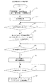
次にこの冷凍冷凍空調装置での運転制御動作について説明する。まず暖房運転時の制御動作について図4に基づいて説明する。図4は暖房運転時の制御動作を示すフローチャートである。暖房運転時には、ステップS1で、まず圧縮機3の容量、第1膨張弁11の開度、第2膨張弁14の開度、第3膨張弁8の開度が初期値に設定される。そして、ステップS2で所定時間経過後そして以降運転状態に応じた各アクチュエータは以下のように制御される。圧縮機3の容量は、基本的に室内機2の第10温度センサ16jで計測される空気温度が、冷凍空調装置使用者が設定する温度になるように制御される。
Next, the operation control operation in this refrigeration / refrigeration air conditioner will be described. First, the control operation during the heating operation will be described with reference to FIG. FIG. 4 is a flowchart showing a control operation during heating operation. During the heating operation, in step S1, the capacity of the
即ち、ステップS3で室内機2の空気温度と設定温度とを比較する。そして、空気温度が設定温度と等しいか或いは近接している場合は、圧縮機3の容量はそのまま維持されて次のステップS5に進み、空気温度が設定温度より大きく低下している場合は、圧縮機3の容量は増加され、空気温度が設定温度に近接している場合には、圧縮機3の容量はそのまま維持され、空気温度が設定温度より高くなる場合には圧縮機3の容量は低下されるというように、ステップS4で圧縮機3の容量を変更する。
That is, in step S3, the air temperature of the indoor unit 2 is compared with the set temperature. If the air temperature is equal to or close to the set temperature, the capacity of the
各膨張弁の制御は以下のように行われる。まず第3膨張弁8は、第8温度センサ16hで検知される高圧冷媒の飽和温度と第9温度センサ16iで検知される室内熱交換器6出口温度との差温で得られる室内熱交換器6出口の冷媒過冷却度SCが予め設定された目標値、例えば10℃になるように制御される。ステップS5で室内熱交換器6出口の冷媒過冷却度SCと目標値とを比較する。ステップS5で冷媒過冷却度SCが目標値より大きい場合には、第3膨張弁8の開度は大きく、冷媒過冷却度SCが目標値より小さい場合には、ステップS6で第3膨張弁8の開度は小さく制御されるように第3膨張弁8の開度を変更する。
Each expansion valve is controlled as follows. First, the third expansion valve 8 is an indoor heat exchanger obtained by the temperature difference between the saturation temperature of the high-pressure refrigerant detected by the
次に第1膨張弁11は、第6温度センサ16fで検知される圧縮機3吸入温度と第3温度センサ16cで検知される低圧冷媒の飽和温度との差温で検知される圧縮機3吸入の冷媒過熱度SHが予め設定された目標値、例えば10℃になるように制御される。即ち、ステップS7で圧縮機3の吸入温度である冷媒過熱度SHと目標値とを比較する。そして、圧縮機3吸入の冷媒過熱度SHが目標値と等しいか或いは近接している場合は、第1膨張弁11の開度はそのまま維持され次のステップS9に進む。また、圧縮機3吸入の冷媒過熱度SHが目標値より大きい場合には、第1膨張弁11の開度は大きく、冷媒過熱度SHが目標値より小さい場合には、第1膨張弁11の開度は小さくされるというように、ステップS8で第1膨張弁11の開度を変更する。
Next, the first expansion valve 11 receives the
次に第2膨張弁14は、第1温度センサ16aで検知される圧縮機3の吐出温度が予め設定された目標値、例えば90℃になるように制御される。即ち、ステップS9で圧縮機3の吐出温度と目標値とを比較する。そして、ステップS9で圧縮機3の吐出温度が目標値と等しいか或いは近接している場合には、第2膨張弁14の開度はそのまま維持されステップ2に戻る。
Next, the
第2膨張弁14の開度を変化させた時の冷媒状態変化は以下のようになる。第2膨張弁14の開度が大きくなると、インジェクション回路13に流れる冷媒流量が増加する。第2内部熱交換器10での熱交換量はインジェクション回路13の流量によって、大きく変化しないので、インジェクション回路13に流れる冷媒流量が増加すると、第2内部熱交換器10でのインジェクション回路13側の冷媒エンタルピ差(図2の点9→10の差)は小さくなり、インジェクションされる冷媒エンタルピ(図2点10)は低下する。
The refrigerant state change when the opening degree of the
従って、インジェクションされた冷媒が合流後の冷媒エンタルピ(図2点12)のエンタルピも低下し、結果、圧縮機3の吐出エンタルピ(図2点1)も低下し、圧縮機3の吐出温度は低下する。逆に第2膨張弁14の開度が小さくなると、圧縮機3の吐出エンタルピは上昇し、圧縮機3の吐出温度は上昇する。従って、第2膨張弁14の開度制御は、圧縮機3の吐出温度が目標値より高い場合には、第2膨張弁14の開度を大きく制御し、逆に吐出温度が目標値より低い場合には第2膨張弁14の開度を小さく制御するようにステップS10で第2膨張弁14の開度を変更し、その後はステップS2に戻る。
Therefore, the enthalpy of the refrigerant enthalpy (
次に冷房運転時の制御動作について図5に基づいて説明する。図5は冷房運転時の制御動作を示すフローチャートである。冷房運転時にはまず、ステップS11で圧縮機3の容量、第1膨張弁11の開度、第2膨張弁14の開度、第3膨張弁8の開度が初期値に設定される。それから、ステップS12で所定時間経過すると、それ以降運転状態に応じた各アクチュエータは以下のように制御される。
Next, the control operation during the cooling operation will be described with reference to FIG. FIG. 5 is a flowchart showing the control operation during the cooling operation. In the cooling operation, first, in step S11, the capacity of the
まず、圧縮機3の容量は、基本的に室内機2の第10温度センサ16jで計測される空気温度が、冷凍空調装置使用者が設定する温度になるように制御される。即ち、ステップS13で室内機2の空気温度と設定温度とを比較する。そして、空気温度が設定温度と等しいか或いは近接している場合には、圧縮機3の容量はそのまま維持されて次のステップS15に進む。また、空気温度が設定温度より大きく上昇している場合は、圧縮機3の容量は増加され、空気温度が設定温度に近接している場合には、圧縮機3の容量はそのまま維持され、空気温度が設定温度より低くなる場合には圧縮機3の容量は低下されるというように、ステップS14で圧縮機3の容量を変更する。
First, the capacity of the
各膨張弁の制御は以下のように行われる。まず第1膨張弁11は、温度センサ16cで検知される高圧冷媒の飽和温度と温度センサ16dで検知される室外熱交換器12出口温度との差温で得られる室外熱交換器12出口の冷媒過冷却度SCが予め設定された目標値、例えば10℃になるように制御される。即ち、ステップS15で室外熱交換器12出口の冷媒過冷却度SCと目標値とを比較する。そして、室外熱交換器12出口の冷媒過冷却度SCが目標値と等しいか或いは近接している場合には、第1膨張弁11の開度はそのまま維持されて次のステップS17に進む。また、室外熱交換器12出口の冷媒過冷却度SCが目標値より大きい場合には、第1膨張弁11の開度は大きく、冷媒過冷却度SCが目標値より小さい場合には、第1膨張弁11の開度は小さく制御されるというようにステップS16で第1膨張弁11の開度を変更する。
Each expansion valve is controlled as follows. First, the first expansion valve 11 is a refrigerant at the outlet of the
次に、第3膨張弁8は、第6温度センサ16fで検知される圧縮機3吸入温度と第8温度センサ16hで検知される低圧冷媒の飽和温度との差温で検知される圧縮機3吸入の冷媒過熱度SHが予め設定された目標値、例えば10℃になるように制御される。即ち、ステップS17で圧縮機3吸入の冷媒過熱度SHと目標値とを比較する。そして、圧縮機3吸入の冷媒過熱度SHと目標値とが等しいか或いは近接している場合には、第3膨張弁8の開度はそのまま維持されて次のステップS9に進む。また、圧縮機3吸入の冷媒過熱度SHが目標値より大きい場合には、第3膨張弁8の開度は大きく、冷媒過熱度SHが目標値より小さい場合には、第3膨張弁8の開度は小さくされるというようにステップS18で変更される。
Next, the third expansion valve 8 is the
次に第2膨張弁14は、第1温度センサ16aで検知される圧縮機3の吐出温度が予め設定された目標値、例えば90℃になるように制御される。即ち、ステップS19で圧縮機3の吐出温度と目標値とを比較する。そして、圧縮機3の吐出温度が目標値と等しいか或いは近接している場合には、第2膨張弁14の開度はそのまま維持されて次のステップS12戻る。また、第2膨張弁14の開度を変化させた時の冷媒状態変化は暖房運転時と同様であるので、圧縮機3の吐出温度が目標値より高い場合には、第2膨張弁14の開度を大きく制御し、逆に吐出温度が目標値より低い場合には第2膨張弁14の開度を小さく制御するというように第2膨張弁14の開度を変更しステップS12に戻る。
Next, the
次にこの実施の形態1の回路構成、および制御によって実現される作用効果について説明する。この装置の構成では、冷暖いずれの運転でも同様の運転を行えるので、以下、特に暖房運転について説明する。この装置の回路構成はいわゆるガスインジェクション回路となっている。即ち、凝縮器となる室内熱交換器6を出た後で中間圧まで減圧された冷媒のうちガス冷媒を圧縮機3にインジェクションする構成となっている。
Next, the circuit configuration of the first embodiment and the operational effects realized by the control will be described. In the configuration of this apparatus, since the same operation can be performed in both the cooling and heating operations, the heating operation will be particularly described below. The circuit configuration of this device is a so-called gas injection circuit. That is, the refrigerant is injected into the
一般には、気液分離器で中間圧の冷媒を液・ガスに分離しインジェクションされる構成が多いが、この装置では、図6に示されるように、第2内部熱交換器10での熱交換により、熱的に液・ガスを分離し、インジェクションする構成としている。
In general, there are many configurations in which an intermediate-pressure refrigerant is separated into liquid and gas by a gas-liquid separator and injected, but in this apparatus, as shown in FIG. 6, heat exchange in the second
ガスインジェクション回路とすることにより以下のような効果が得られる。まずガスインジェクションを行うことにより、圧縮機3から吐出される冷媒流量が増加し、圧縮機3から吐出される冷媒流量Gdis=圧縮機3で吸入される冷媒流量Gsuc+インジェクションされる冷媒流量Ginjとなる。従って凝縮器となる熱交換器に流れる冷媒流量が増加するので、暖房運転の場合には、暖房能力が増加する。
By using a gas injection circuit, the following effects can be obtained. First, by performing gas injection, the refrigerant flow rate discharged from the
一方、第2内部熱交換器10での熱交換により図6に示されるように、蒸発器となる熱交換器に流入する冷媒エンタルピが低下し、蒸発器での冷媒エンタルピ差が増大する。従って冷房運転時においても、冷房能力が増加する。
On the other hand, as shown in FIG. 6 due to heat exchange in the second
また、ガスインジェクションを行う場合は効率改善効果も得られる。蒸発器となる熱交換器に流入する冷媒は、一般に気液二相冷媒であるが、このうちガス冷媒は冷房能力に寄与しない。圧縮機3から見ると、この低圧のガス冷媒も、蒸発器で蒸発したガス冷媒と一緒に高圧に昇圧する仕事を行っている。ガスインジェクションを行うと、蒸発器に流入するガス冷媒のうちのいくらかを中間圧で抜き出して、インジェクションし、中間圧から高圧に昇圧し圧縮することになる。従ってインジェクションされるガス冷媒の流量については、低圧から中間圧まで昇圧する圧縮仕事が不要になり、この分効率改善される。この効果は冷暖房のいずれの運転でも得られる。
In addition, when gas injection is performed, an efficiency improvement effect can be obtained. The refrigerant flowing into the heat exchanger serving as an evaporator is generally a gas-liquid two-phase refrigerant, but among these, the gas refrigerant does not contribute to the cooling capacity. When viewed from the
次にガスインジェクション流量と暖房能力の相関について説明する。ガスインジェクション流量を増加すると、前述したように圧縮機3から吐出される冷媒流量は増加する一方で、圧縮機3吐出温度は低下し凝縮器となる室内熱交換器6に流入する冷媒温度も低下する。凝縮器の熱交換性能を見ると、一般に熱交換器内での温度分布が高い程熱交換量が増加する。同一凝縮温度で凝縮器入口の冷媒温度が異なる場合の冷媒温度変化は図7に示すようになり、凝縮器内で冷媒が過熱ガス状態である部分の温度分布が異なってくる。
Next, the correlation between the gas injection flow rate and the heating capacity will be described. When the gas injection flow rate is increased, the refrigerant flow rate discharged from the
凝縮器では冷媒が凝縮温度で二相状態にあるときの熱交換量が多くを占めるが、過熱ガス状態である部分の熱交換量も全体の20%〜30%程度存在し、熱交換量への影響は大きい。インジェクション流量が多くなりすぎ、過熱ガス部分での冷媒温度の低下が著しいと、凝縮器での熱交換性能が低下し、暖房能力も低下する。上記のガスインジェクション流量と暖房能力の相関を表すと図8のようになり、暖房能力が最大となるガスインジェクション流量が存在する。 In the condenser, the heat exchange amount when the refrigerant is in the two-phase state at the condensation temperature occupies a large amount, but the heat exchange amount of the part that is in the superheated gas state is also about 20% to 30% of the total, and the heat exchange amount The impact of is great. If the injection flow rate is excessively increased and the refrigerant temperature is significantly reduced in the superheated gas portion, the heat exchange performance in the condenser is lowered and the heating capacity is also lowered. The correlation between the gas injection flow rate and the heating capacity is shown in FIG. 8, and there is a gas injection flow rate at which the heating capacity is maximized.
次にこの実施の形態1における中圧レシーバ9内での圧縮機3吸入配管18の貫通配管18aとの熱交換冷媒9aとの作用効果について説明する。中圧レシーバ9では、暖房運転時には第3膨張弁8を出た気液二相冷媒が流入し、中圧レシーバ9内で圧縮機3吸入配管18の貫通配管18aとの熱交換冷媒9aとの熱交換により冷却され液となって流出する。冷房運転時には第2内部熱交換器10出口の気液二相冷媒が流入し、中圧レシーバ9内で冷却され液となって流出することにより、蒸発器となる室内熱交換器6に流入する冷媒のエンタルピは低くなるので、蒸発器での冷媒エンタルピ差が拡大される。従って冷房運転時には冷房能力が増加する。
Next, the effect of the heat exchange refrigerant 9a with the through pipe 18a of the
一方、圧縮機3に吸入される冷媒は加熱され、吸入温度が上昇する。これに伴い圧縮機3の吐出温度も上昇する。また圧縮機3の圧縮行程では、同じ昇圧を行う場合でも一般的に高温の冷媒を圧縮するほどより多くの仕事を必要とする。従って、中圧レシーバ9内での圧縮機3吸入配管18の貫通配管18aとの熱交換冷媒9aとの熱交換による効率面での影響は、蒸発器エンタルピ差拡大による能力増加と、圧縮仕事の増加の両面が表れ、蒸発器エンタルピ差拡大による能力増加の影響が大きい場合には、装置の運転効率が上昇する。
On the other hand, the refrigerant sucked into the
また、中圧レシーバ9内での吸入配管18の貫通配管18aとの熱交換冷媒9aとの熱交換は、主に気液二相冷媒のうちガス冷媒が吸入配管18の貫通配管18aとの熱交換冷媒9aと触れて凝縮液化して熱交換される。従って、中圧レシーバ9内に滞留する液冷媒量が少ないほど、ガス冷媒と吸入配管18の貫通配管18aとの熱交換冷媒9aが接触する面積が多くなり、熱交換量は増加する。逆に、中圧レシーバ9内に滞留する液冷媒量が多いと、ガス冷媒と吸入配管18の貫通配管18aとの熱交換冷媒9aが接触する面積が少なくなり、熱交換量は減少する。
Further, heat exchange with the heat exchange refrigerant 9a with the through pipe 18a of the
このように中圧レシーバ9を備えることで以下の効果を持つ。まず、中圧レシーバ9出口は液となるので、暖房運転時に第2膨張弁14に流入する冷媒は、必ず液冷媒となるので、第2膨張弁14の流量特性が安定し、制御安定性が確保され、安定した装置運転を行うことができる。
By providing the
また中圧レシーバ9内で熱交換を行うことで中圧レシーバ9の圧力が安定的になり、第2膨張弁14入口圧力が安定し、インジェクション回路13に流れる冷媒流量が安定するという効果もある。例えば負荷変動などがあり、高圧が変動したりすると、それに伴い中圧レシーバ9内の圧力変動が生じるが、中圧レシーバ9内の熱交換により圧力変動が抑制される。負荷が増加し、高圧が上昇すると中圧レシーバ9内の圧力も上昇するが、そのときには、低圧との圧力差が広がり、中圧レシーバ9内の熱交換での温度差も広がるので熱交換量が増加する。熱交換量が増加すると、中圧レシーバ9に流入する気液二相冷媒のうちのガス冷媒が凝縮する量が多くなるので、圧力が上がりにくくなり、中圧レシーバ9の圧力上昇が抑制される。逆に、負荷が減少し、高圧が低下すると中圧レシーバ9内の圧力も低下するが、そのときには、低圧との圧力差が狭まり、中圧レシーバ9内の熱交換での温度差も狭まるので熱交換量が減少する。熱交換量が減少すると、中圧レシーバ9に流入する気液二相冷媒のうちのガス冷媒が凝縮する量が少なくなるので、圧力が下がりにくくなり、中圧レシーバ9の圧力は低下が抑制される。
Further, by exchanging heat in the
このように、中圧レシーバ9内で熱交換を行うことにより、運転状態変動に伴う熱交換量変動が自律的に発生し、その結果として中圧レシーバ9内の圧力変動が抑制される。
As described above, by performing heat exchange in the
また中圧レシーバ9内で熱交換を行うことで装置運転そのものが安定するという効果もある。例えば低圧側の状態が変動し、蒸発器である室外熱交換器12出口の冷媒過熱度が大きくなった場合には、中圧レシーバ9内での熱交換の際の温度差が減少するため、熱交換量が減少し、ガス冷媒が凝縮されにくくなるので、中圧レシーバ9内のガス冷媒量が増加し、液冷媒量が減少する。減少した分の液冷媒量は、室外熱交換器12に移動し、室外熱交換器12内の液冷媒量が増加することから、室外熱交換器12出口の冷媒過熱度が大きくなることが抑制され、装置の運転変動が抑制される。逆に、低圧側の状態が変動し、蒸発器である室外熱交換器12出口の冷媒過熱度が小さくなった場合には、中圧レシーバ9内での熱交換の際の温度差が増加するため、熱交換量が増加し、ガス冷媒が凝縮されやすくなるので、中圧レシーバ9内のガス冷媒量が減少し、液冷媒量が増加する。この分の液冷媒量は、室外熱交換器12から移動することになり、室外熱交換器12内の液冷媒量が減少することから、室外熱交換器12出口の冷媒過熱度が小さくなることが抑制され、装置の運転変動が抑制される。
Further, the heat exchange in the
この過熱度変動を抑制する作用も、中圧レシーバ9内で熱交換を行うことにより、運転状態変動に伴う熱交換量変動が自律的に発生することによって生じている。
The action of suppressing the fluctuation in superheat degree is also caused by the fact that the heat exchange amount fluctuation accompanying the fluctuation of the operation state is autonomously generated by performing heat exchange in the
次にこの実施の形態1のように、中圧レシーバ9内での熱交換と、インジェクション回路13によるガスインジェクションを組み合わせた場合の効果について説明する。中圧レシーバ9内での熱交換を行うと、圧縮機3吸入温度が上昇する。従って、インジェクションを行った場合の圧縮機3内部の変化においては、低圧から中間圧に昇圧された冷媒エンタルピ(図2、図3の点11)が高くなり、インジェクションされる冷媒と合流した後の冷媒エンタルピ(図2、図3の点12)も高くなる。従って圧縮機3の吐出エンタルピ(図2、図3の点1)も高くなり、圧縮機3の吐出温度は上昇する。そこで、中圧レシーバ9内での熱交換の有無に伴う、ガスインジェクション流量と暖房能力の相関の変化を表すと図9のようになる。中圧レシーバ9内での熱交換が有る場合には、同一インジェクション量を行った場合の圧縮機3吐出温度は高くなるので、凝縮器入口の冷媒温度も高くなり、凝縮器熱交換量が増加し、暖房能力が増加する。従って暖房能力ピークとなるインジェクション流量が増加し、暖房能力のピーク値そのものも増加し、より多くの暖房能力を得ることができる。
Next, the effect of combining heat exchange in the
ここで更に暖房能力を増加させたい場合には、インジェクション回路13中に電気ヒータ等の冷媒加熱用熱源17を設ける事で、圧縮機3吐出温度の低下を抑制しつつインジェクション流量を増加させる事が可能となり、図9に示す様に暖房能力のピーク値そのものをさらに増加させる事が可能となる。
Here, when it is desired to further increase the heating capacity, it is possible to increase the injection flow rate while suppressing the decrease in the discharge temperature of the
なお、中圧レシーバ9内での熱交換が存在しない場合でも、第1膨張弁11の開度制御により、圧縮機3の吸入過熱度を上昇させて、圧縮機3の吐出温度を上昇させることができる。しかしこの場合は、同時に蒸発器となる室外熱交換器12出口の冷媒過熱度も大きくなることから、室外熱交換器12の熱交換効率が低下する。室外熱交換器12の熱交換効率が低下すると、同一熱交換量を得るためには、蒸発温度を低下させねばならず、低圧の低下する運転となる。低圧が低下すると、圧縮機3で吸入される冷媒流量も減少するため、このような運転を行うと、かえって暖房能力を低下させることになる。逆にいうと、中圧レシーバ9内での熱交換を行うと、蒸発器となる室外熱交換器12出口の冷媒状態が適切な状態とし、熱交換効率のよい状態のまま、圧縮機3吐出温度を上昇させることができ、前記のような低圧の低下を回避し、暖房能力増加を容易に実現できる。
In addition, even when there is no heat exchange in the
また、この実施の形態1の回路構成では、高圧冷媒の一部をバイパスし減圧後、第2内部熱交換器10で過熱ガス化したあとインジェクションを行う構成をとっている。従って、従来例のように気液分離器を用いて分離したガスをインジェクションする場合に比べ、制御や運転状態などに応じてインジェクション量が変化したときの冷媒量分布の変動が発生しないので、より安定した運転を実現できる。
Further, in the circuit configuration of the first embodiment, a part of the high-pressure refrigerant is bypassed and decompressed, and after being superheated and gasified by the second
なお、中圧レシーバ9で熱交換を行う構造であるが、中圧レシーバ9内の冷媒と熱交換する構成であればどのような構成をとっても同様の効果を得ることができる。例えば、中圧レシーバ9容器外周に圧縮機3の吸入配管を接触させて熱交換させる構成を用いてもよい。
In addition, although it is the structure which heat-exchanges with the
また、インジェクション回路13に供給する冷媒を中圧レシーバ9底部から供給してもよい。この場合には、冷暖房の各運転で、第2膨張弁14に液冷媒が流入することになるので、冷暖いずれの運転においても第2膨張弁14の流量特性が安定し、制御安定性が確保される。
Further, the refrigerant supplied to the
なお、第2膨張弁14は圧縮機3の吐出温度が目標値となるように制御すると前述したが、この制御目標値は暖房能力が最大となるように設定する。図9に示したように、ガスインジェクション流量−暖房能力−吐出温度の相関から、暖房能力最大となる吐出温度が存在するので、予めこの吐出温度を求めておいて目標値に設定する。なお、吐出温度の目標値は必ずしも一定値である必要は無く、運転条件や凝縮器などの機器の特性に応じて随時変更してもよい。このように吐出温度制御を行うことで、ガスインジェクション量を暖房能力最大となるように制御できる。
Although the
ガスインジェクション量については暖房能力最大となるようにするだけでなく、運転効率最大となるように制御することもできる。冷凍空調装置起動時のように、多量の暖房能力を必要とする場合は能力最大に制御するが、装置を一定時間運転後、暖房により室温が上昇した場合などには、それほど多くの暖房能力を必要としなくなるので、このような場合には、効率最大となるように制御する。インジェクション流量と暖房能力と運転効率の間には、図10に示すような相関があり、暖房能力最大となる場合に比べ、運転効率最大となるインジェクション流量は少なく、吐出温度は高くなる。暖房能力最大となるインジェクション流量では、吐出温度を低くしていることから、凝縮器の熱交換性能が低下していること、またインジェクション流量を多くするために、中間圧力が低くなり、インジェクション分を圧縮する圧縮仕事が多くなることにより、運転効率最大となる場合に比べ効率が低下する。 The gas injection amount can be controlled not only to maximize the heating capacity but also to maximize the operating efficiency. When a large amount of heating capacity is required, such as when the refrigeration air conditioner is activated, the maximum capacity is controlled. In such a case, control is performed to maximize efficiency. There is a correlation as shown in FIG. 10 between the injection flow rate, the heating capacity, and the operation efficiency. Compared with the case where the heating capacity is maximum, the injection flow rate that maximizes the operation efficiency is small and the discharge temperature is high. At the injection flow rate at which the heating capacity is maximized, the discharge temperature is lowered, so that the heat exchange performance of the condenser is lowered, and in order to increase the injection flow rate, the intermediate pressure is lowered and the injection amount is reduced. By increasing the compression work to be compressed, the efficiency is reduced as compared with the case where the operation efficiency is maximized.
そこで、第2膨張弁14で制御する吐出温度目標値として、暖房能力最大となる目標値だけでなく運転効率最大となる目標値も持ち、運転状況、例えば圧縮機3の運転容量や、室内機側空気温度の状況に応じて、暖房能力が必要とされるときは、暖房能力最大となる目標値に設定し、そうでない場合は運転効率最大となる目標値に設定する。このような運転を行うことにより、多量の暖房能力を実現するとともに、効率の高い装置の運転を行うことができる。
Therefore, the discharge temperature target value controlled by the
また第1膨張弁11は圧縮機3の吸入過熱度が目標値となるように制御するとしたが、この制御により蒸発器となる熱交換器出口の過熱度を最適にでき、蒸発器での熱交換性能を高く確保するとともに、冷媒エンタルピ差も適度に確保するように運転することができ、高効率の運転を行うことができる。このような運転となる蒸発器出口の過熱度は熱交換器の特性によって異なるが、概ね2℃前後であり、それから中圧レシーバ9で冷媒が加熱されるので、圧縮機3の吸入過熱度の目標値はこの値より高くなり、例えば前述した10℃が目標値に設定される。
Further, the first expansion valve 11 is controlled so that the suction superheat degree of the
従って、第1膨張弁11の制御としては、蒸発器出口の過熱度、暖房運転の場合は第2温度センサ16bと第3温度センサ16cの差温で求められる室外熱交換器12出口の過熱度が目標値、例えば、前述した2℃になるように制御してもよい。ただし、蒸発器出口の過熱度を直接制御する場合、その目標値が2℃程度と低い値である場合には過渡的に蒸発器出口が気液二相状態となり、過熱度が適切に検知できず制御が難しくなることが生じる。圧縮機3の吸入過熱度で検知すると、目標値を高く設定できるとともに中圧レシーバ9での加熱により、吸入が気液二相となって過熱度が適切に検知できないという状況は発生しないので、制御としては、より容易に行うことができ、安定した制御を行うことができる。
Therefore, the control of the first expansion valve 11 includes the degree of superheat at the outlet of the evaporator, and the degree of superheat at the outlet of the
また第3膨張弁8は凝縮器となる室内熱交換器6出口の過冷却度が目標値となるように制御するとしたが、この制御により凝縮器での熱交換性能を高く確保するとともに、冷媒エンタルピ差も適度に確保するように運転することができ、高効率の運転を行うことができる。このような運転となる凝縮器出口の過冷却度は熱交換器の特性によって異なるが概ね5〜10℃前後である。なお、過冷却度の目標値はこの値より高く設定する、例えば10〜15℃前後に設定することによって、暖房能力を増加した運転も行うことができる。そこで運転状況に応じて、過冷却度の目標値を変更し、装置起動時は高めの過冷却度目標値で暖房能力確保、室温安定時は低めの過冷却度目標値で高効率運転を行うようにすることもできる。 The third expansion valve 8 is controlled so that the degree of supercooling at the outlet of the indoor heat exchanger 6 serving as a condenser becomes a target value. This control ensures high heat exchanging performance in the condenser and the refrigerant. The operation can be performed so as to ensure an appropriate enthalpy difference, and a highly efficient operation can be performed. The degree of supercooling at the outlet of the condenser for such operation varies depending on the characteristics of the heat exchanger, but is generally around 5 to 10 ° C. In addition, the operation which increased the heating capability can also be performed by setting the target value of a supercooling degree higher than this value, for example, setting to about 10-15 degreeC. Therefore, the target value of the degree of supercooling is changed according to the operating status, heating capacity is secured with a higher target value of supercooling when starting up the device, and high efficiency operation is performed with a lower target value of subcooling when the room temperature is stable. It can also be done.
なお、冷凍空調装置の冷媒としては、R410Aに限るものではなく、他の冷媒、にも用いることができる。 In addition, as a refrigerant | coolant of a refrigerating / air-conditioning apparatus, it can use not only for R410A but another refrigerant | coolant.
また、中圧レシーバ9、第2内部熱交換器10の配置位置は図1に示す冷媒回路構成に限るものではなく、上流下流の位置関係が反対であっても同様の効果を得ることができる。またインジェクション回路13を取り出す位置も図1に示す冷媒回路位置に限るものではなく、他の中間圧部分、および高圧液部から取り出せる位置であれば同様の効果を得ることができる。なお、第2膨張弁14の制御安定性を考慮するとインジェクション回路13を取り出す位置としては、気液二相状態であるよりは完全に液となっている位置の方が望ましい。
Further, the arrangement positions of the
なお、この実施の形態1では、第1膨張弁11、第3膨張弁8の間に中圧レシーバ9、第2内部熱交換器10、およびインジェクション回路13の取り出し位置を配置しているので、冷暖いずれの運転モードでも同様のインジェクションを行った運転を実施できる。
In the first embodiment, since the
また、冷媒の飽和温度を凝縮器、蒸発器中間の冷媒温度センサで検知しているが、高低圧を検知する圧力センサを設け、検出された圧力値を換算して飽和温度を求めてもよい。 Further, the refrigerant saturation temperature is detected by the refrigerant temperature sensor between the condenser and the evaporator. However, a pressure sensor for detecting high and low pressures may be provided, and the detected pressure value may be converted to obtain the saturation temperature. .
図11は、冷凍空調装置での暖房除霜運転時の制御動作を示すフロー図である。図11において、前記に示す暖房運転を実施し、ステップS21で、まず圧縮機3の容量、第1膨張弁11の開度、第2膨張弁14の開度、第3膨張弁8の開度が初期値に設定される。そして、ステップS22で所定時間経過後そして以降運転状態に応じた各アクチュエータは以下のように制御される。圧縮機3の容量は、基本的に室外機1の第2温度センサ16b、第3温度センサ16c、第4温度センサ16dで計測される空外温度が、冷凍空調装置使用者が設定する温度になるように制御される。
FIG. 11 is a flowchart showing a control operation during heating defrosting operation in the refrigeration air conditioner. In FIG. 11, the heating operation described above is performed, and in step S21, first, the capacity of the
即ち、ステップS23で室外機1の室外配管温度と設定温度とを比較する。そして、室外配管温度が設定温度と等しいか或いは所定値以下(例えばー5℃)となった場合には、蒸発器である室外熱交換器12への着霜と判定し、ステップS24へ進み、四方弁を切替え除霜運転開始する。具体的には冷房時と同様のサイクルとし、圧縮機3より吐出された高圧・高温冷媒を室外熱交換器12に流し、除霜運転を実施する。その際、第2膨張弁14を開きかつ冷媒加熱用熱源17により冷媒を加熱することで、吐出温度の低下を抑制しつつガスインジェクションを行い凝縮器へ流れる冷媒循環量を増加させる。このことで除霜運転時間の短縮化が図れる。
That is, in step S23, the outdoor piping temperature of the outdoor unit 1 is compared with the set temperature. If the outdoor pipe temperature is equal to the set temperature or less than a predetermined value (for example, −5 ° C.), it is determined that the
次にステップS25で凝縮器である室外配管温度と設定温度とを比較する。そして、室外配管温度が設定温度と等しいか或いは所定値以上(例えば8℃)となった場合には、ステップS26に進み、着霜の溶解が終了したと判断し四方弁4を切替え暖房運転に復帰し運転を再開する。その際も第2膨張弁14を開きインジェクションを行い、かつ冷媒加熱用熱源17により加熱を行うことにより除霜運転時と同様吐出温度の低下を抑制しつつ凝縮器への冷媒循環量の増加を図れ、暖房能力が増加するため暖房運転の立ち上がりを早めることができる。次に、ステップS27で室内配管温度と設定温度とを比較する。そして、室内配管温度が設定温度と等しいか或いは所定値以下であれば、ステップS28に進み第2膨張弁14を閉じインジェクションを終了するとともに、冷媒加熱用熱源17の加熱も終了とする。
Next, in step S25, the outdoor piping temperature, which is a condenser, is compared with the set temperature. If the outdoor piping temperature is equal to the set temperature or is equal to or higher than a predetermined value (for example, 8 ° C.), the process proceeds to step S26, where it is determined that the melting of frost has ended and the four-way valve 4 is switched to the heating operation. Return and resume operation. At that time, the
次に暖房除霜運転時に実現される作用効果について説明する。暖房運転時における室外熱交換器12の冷媒配管への着霜を冷媒の熱により溶解させる除霜運転は、四方弁4を切り替え冷房運転時と同様に冷媒を流す事で実施される。その際、第2膨張弁14を開き圧縮機3へのガスインジェクションを行う事で、圧縮機3から吐出される冷媒流量が増加し凝縮器である室外熱交換器12に流入する冷媒流量が増える一方、上記の様に圧縮機3吐出温度は低下する傾向となる。従いこの場合も凝縮器での熱交換性能が最大となる、
Next, the effect achieved during the heating defrosting operation will be described. The defrosting operation in which frost formation on the refrigerant pipe of the
すなわち、図12に示すように除霜時間が最短となるガスインジェクション流量が存在することとなる。なお、この実施の形態においては上記の様に中圧レシーバ9での熱交換があるため、より高い改善効果、すなわち除霜時間の短縮化が図れる。
That is, as shown in FIG. 12, there is a gas injection flow rate at which the defrost time is the shortest. In addition, in this embodiment, since there is heat exchange at the
また除霜運転終了後の暖房運転への切り替わりに時にガスインジェクションを行う事で、高い暖房能力すなわち暖房運転の立ち上がりを良くする事が可能となる。 Further, by performing gas injection at the time of switching to the heating operation after the completion of the defrosting operation, it becomes possible to improve the high heating capacity, that is, the rising of the heating operation.
ここでインジェクション回路13に設けた、電気ヒータ等の冷媒加熱用熱源を使用する事で、圧縮機3吐出温度の低下を抑制しつつ、更にインジェクション冷媒量を増加される事が可能となるため、更なる除霜時間の短縮化が図れ、また暖房運転復帰時にも使用する事で、暖房運転立ち上がりの更なる改善が実現できる。
By using a heat source for heating the refrigerant such as an electric heater provided in the
なお、上記説明は暖房復帰時のインジェクション実施期間を暖房能力値がある所定値になるまでと規定したが、凝縮温度での制御や、予め実施期間を規定しておくなどの制御でも同様の効果は得られる。 In addition, although the said description prescribed | regulated that the injection implementation period at the time of heating return was until a heating capability value became a predetermined value, the same effect is also obtained by control at the condensation temperature or control such as prescribing the implementation period in advance. Is obtained.
1 室外機、2 室内機、3 圧縮機、4 四方弁、5 ガス管、6 室内熱交換器、7 液管、8 第3膨張弁、9 中圧レシーバ、9a 熱交換冷媒、10 第2内部熱交換器、11 第1膨張弁、12 室外熱交換器、13 インジェクション回路、14 第2膨張弁、16a 第1温度センサ、16b 第2センサ、16c 第3センサ、16d 第4センサ、16e 第5センサ、16f 第6センサ、16g 第7センサ、16h 第8センサ、16i 第9センサ、16j 第10センサ、17 冷媒加熱用熱源、18 吸入配管、18a 貫通部配管。 DESCRIPTION OF SYMBOLS 1 Outdoor unit, 2 Indoor unit, 3 Compressor, 4 Four way valve, 5 Gas pipe, 6 Indoor heat exchanger, 7 Liquid pipe, 8 3rd expansion valve, 9 Medium pressure receiver, 9a Heat exchange refrigerant, 10 2nd inside 11 heat exchanger, 11 first expansion valve, 12 outdoor heat exchanger, 13 injection circuit, 14 second expansion valve, 16a first temperature sensor, 16b second sensor, 16c third sensor, 16d fourth sensor, 16e fifth Sensor, 16f 6th sensor, 16g 7th sensor, 16h 8th sensor, 16i 9th sensor, 16j 10th sensor, 17 Heat source for refrigerant heating, 18 Intake pipe, 18a Through-hole pipe.
Claims (24)
前記負荷側熱交換器(6)から前記蒸発器(12)に向かって流れる冷媒を貯留するとともに、その貯留された冷媒と前記蒸発器(12)から前記圧縮機(3)に向かう冷媒との間で熱交換させるレシーバ(9)と、
前記負荷側熱交換器(6)から前記蒸発器(12)に向かって流れる冷媒の一部を、前記蒸発器(12)を経て前記圧縮機(3)に吸入されて中間圧に圧縮された冷媒に合流させるバイパス経路(13)と、
前記バイパス経路(13)に設けられ、前記パイパス経路(13)を流れる冷媒の圧力を下げる第2膨張弁(14)と、
前記主冷媒回路及び前記バイパス経路(13)に設けられ、前記負荷側熱交換器(6)から前記蒸発器(12)に向かって流れる冷媒の熱を、前記バイパス経路(13)を流れる冷媒に与える内部熱交換器(10)と、
前記第1膨張弁(11)及び前記第2膨張弁(14)の開度を制御する制御装置(15)と、
を有する
ことを特徴とするヒートポンプ装置。 An evaporator (12) for absorbing heat into the refrigerant, a compressor (3) for sucking the refrigerant from the evaporator (12), and a four-way valve (4) through which the refrigerant discharged from the compressor (3) passes And a load-side heat exchanger (6) that dissipates heat of the refrigerant discharged from the compressor (3), and a pressure of the refrigerant flowing from the load-side heat exchanger (6) to the evaporator (12). a first expansion valve (11) to lower, but has a connected main refrigerant circuit so as to circulate the refrigerant in the heat pump apparatus utilizing the heat radiation thermal from the load-side heat exchanger (6),
While storing the refrigerant | coolant which flows toward the said evaporator (12) from the said load side heat exchanger (6), the stored refrigerant | coolant and the refrigerant | coolant which goes to the said compressor (3) from the said evaporator (12) A receiver (9) for exchanging heat between,
Part of the refrigerant flowing toward the evaporator (12) from the load-side heat exchanger (6), compressed to an intermediate pressure is sucked into the compressor through the evaporator (12) (3) A bypass path (13) for joining the refrigerant;
A second expansion valve (14) provided in the bypass path (13) for reducing the pressure of the refrigerant flowing through the bypass path (13);
Provided in the main refrigerant circuit and the bypass path (13), the heat of the refrigerant flowing from the load side heat exchanger (6) toward the evaporator (12) is converted into the refrigerant flowing through the bypass path (13). Giving internal heat exchanger (10);
A control device (15) for controlling the opening degree of the first expansion valve (11) and the second expansion valve (14);
A heat pump device characterized by comprising:
前記温度センサ(16a)の検知結果に基づき前記第2膨張弁(14)の開度を制御する
ことを特徴とする請求項1に記載のヒートポンプ装置。 A temperature sensor (16a) for detecting the temperature of the refrigerant discharged from the compressor (3), the control device (15),
The heat pump device according to claim 1, wherein the opening degree of the second expansion valve (14) is controlled based on a detection result of the temperature sensor (16a).
前記第2膨張弁(14)の開度を制御して、前記温度センサ(16a)で検知する吐出温度を所定の範囲とする
ことを特徴とする請求項1に記載のヒートポンプ装置。 A temperature sensor (16a) for detecting the temperature of the refrigerant discharged from the compressor (3), the control device (15),
The heat pump apparatus according to claim 1, wherein the opening temperature of the second expansion valve (14) is controlled to set a discharge temperature detected by the temperature sensor (16a) within a predetermined range.
前記第2膨張弁(14)によって気液二相状態になる
ことを特徴とする請求項1〜3のいずれかに記載のヒートポンプ装置。 The refrigerant flowing through the bypass path (13) is
The heat pump device according to any one of claims 1 to 3, wherein a gas-liquid two-phase state is obtained by the second expansion valve (14).
ことを特徴とする請求項1〜4のいずれかに記載のヒートポンプ装置。 The heat pump device according to any one of claims 1 to 4, further comprising a third expansion valve (8) between the load-side heat exchanger (6) and the receiver (9).
前記負荷側熱交換器(6)から前記レシーバ(9)に向かって流れる冷媒の圧力を下げるものである
ことを特徴とする請求項5に記載のヒートポンプ装置。 The third expansion valve (8)
The heat pump device according to claim 5, wherein the pressure of the refrigerant flowing from the load-side heat exchanger (6) toward the receiver (9) is reduced.
前記負荷側熱交換器(6)と前記第1膨張弁(11)との間から分岐している
ことを特徴とする請求項1〜6のいずれかに記載のヒートポンプ装置。 The bypass path (13)
The heat pump device according to any one of claims 1 to 6, wherein the heat pump device is branched from between the load-side heat exchanger (6) and the first expansion valve (11).
前記レシーバ(9)と前記内部熱交換器(10)との間から分岐している
ことを特徴とする請求項7に記載のヒートポンプ装置。 The bypass path (13)
The heat pump device according to claim 7, wherein the heat pump device is branched from between the receiver (9) and the internal heat exchanger (10).
ことを特徴とする請求項1〜8のいずれかに記載のヒートポンプ装置。 The heat pump device according to any one of claims 1 to 8, wherein a heat source (17) for heating the refrigerant is provided in the bypass path (13).
ことを特徴とする請求項1〜9のいずれかに記載のヒートポンプ装置。 The heat pump device according to any one of claims 1 to 9, wherein air is heated by the heat discharged from the compressor (3) in the load-side heat exchanger (6) to dissipate heat.
ことを特徴とする請求項1〜9のいずれかに記載のヒートポンプ装置。 The heat pump device according to any one of claims 1 to 9, wherein water is heated when the refrigerant discharged from the compressor (3) dissipates heat in the load-side heat exchanger (6).
前記制御装置(15)は、
前記吐出温度センサ(16a)によって検知される冷媒の吐出温度が、目標値よりも高い場合には冷媒のエンタルピを下げるように前記第2膨張弁(14)の開度を大きく制御し、目標値よりも低い場合には冷媒のエンタルピを上げるように前記第2膨張弁(14)の開度を小さく制御する
ことを特徴とする請求項2〜11のいずれかに記載のヒートポンプ装置。 A temperature sensor (16a) for detecting the temperature of the refrigerant discharged from the compressor (3);
The control device (15)
When the refrigerant discharge temperature detected by the discharge temperature sensor (16a) is higher than the target value, the opening of the second expansion valve (14) is largely controlled so as to reduce the enthalpy of the refrigerant, and the target value The heat pump device according to any one of claims 2 to 11, wherein the opening degree of the second expansion valve (14) is controlled to be small so that the enthalpy of the refrigerant is increased when the temperature is lower than the lower limit.
前記負荷側熱交換器(6)から前記蒸発器(12)に向かって流れる冷媒を貯留するとともに、その貯留された冷媒と前記蒸発器(12)から前記圧縮機(3)に向かう冷媒との間で熱交換させるレシーバ(9)と、
前記負荷側熱交換器(6)から前記蒸発器(12)に向かって流れる冷媒の一部を、前記蒸発器(12)を経て前記圧縮機(3)に吸入されて中間圧に圧縮された冷媒に合流させるバイパス経路(13)と、
前記バイパス経路(13)に設けられ、前記パイパス経路(13)を流れる冷媒の圧力を下げる第2膨張弁(14)と、
前記主冷媒回路及び前記バイパス経路(13)に設けられ、前記負荷側熱交換器(6)から前記蒸発器(12)に向かって流れる冷媒の熱を、前記バイパス経路(13)を流れる冷媒に与える内部熱交換器(10)と、
前記第1膨張弁(11)及び前記第2膨張弁(14)の開度を制御する制御装置(15)と、
を有する
ことを特徴とするヒートポンプ装置の室外機。 An evaporator (12) that absorbs heat to the refrigerant, and a refrigerant that is drawn into the load side heat exchanger (6) that sucks the refrigerant from the evaporator (12) and radiates the heat of the refrigerant through the four-way valve (4). The compressor (3) for discharging and the first expansion valve (11) for reducing the pressure of the refrigerant flowing from the load side heat exchanger (6) to the evaporator (12) are connected to circulate the refrigerant. In the outdoor unit of the heat pump device that has the main refrigerant circuit and uses the heat radiated from the load side heat exchanger (6),
While storing the refrigerant | coolant which flows toward the said evaporator (12) from the said load side heat exchanger (6), the stored refrigerant | coolant and the refrigerant | coolant which goes to the said compressor (3) from the said evaporator (12) A receiver (9) for exchanging heat between,
Part of the refrigerant flowing toward the evaporator (12) from the load-side heat exchanger (6), compressed to an intermediate pressure is sucked into the compressor through the evaporator (12) (3) A bypass path (13) for joining the refrigerant;
A second expansion valve (14) provided in the bypass path (13) for reducing the pressure of the refrigerant flowing through the bypass path (13);
Provided in the main refrigerant circuit and the bypass path (13), the heat of the refrigerant flowing from the load side heat exchanger (6) toward the evaporator (12) is converted into the refrigerant flowing through the bypass path (13). Giving internal heat exchanger (10);
A control device (15) for controlling the opening degree of the first expansion valve (11) and the second expansion valve (14);
An outdoor unit of a heat pump device characterized by comprising:
前記制御装置(15)は、
前記温度センサ(16a)の検知結果に基づき前記第2膨張弁(14)の開度を制御する
ことを特徴とする請求項13に記載のヒートポンプ装置の室外機。 A temperature sensor (16a) for detecting the temperature of the refrigerant discharged from the compressor (3);
The control device (15)
The outdoor unit of the heat pump device according to claim 13, wherein the opening degree of the second expansion valve (14) is controlled based on a detection result of the temperature sensor (16a).
前記制御装置(15)は、
前記第2膨張弁(14)の開度を制御して、前記温度センサ(16a)で検知する吐出温度を所定の範囲とする
ことを特徴とする請求項13に記載のヒートポンプ装置の室外機。 A temperature sensor (16a) for detecting the temperature of the refrigerant discharged from the compressor (3);
The control device (15)
The outdoor unit of the heat pump apparatus according to claim 13, wherein the opening temperature of the second expansion valve (14) is controlled to set a discharge temperature detected by the temperature sensor (16a) within a predetermined range.
前記第2膨張弁(14)によって気液二相状態になる
ことを特徴とする請求項13〜15のいずれかに記載のヒートポンプ装置の室外機。 The refrigerant flowing through the bypass path (13) is
The outdoor unit of the heat pump apparatus according to any one of claims 13 to 15, wherein the second expansion valve (14) is in a gas-liquid two-phase state.
ことを特徴とする請求項13〜16のいずれかに記載のヒートポンプ装置の室外機。 The outdoor unit of the heat pump device according to any one of claims 13 to 16, further comprising a third expansion valve (8) between the load-side heat exchanger (6) and the receiver (9). .
前記負荷側熱交換器(6)から前記レシーバ(9)に向かって流れる冷媒の圧力を下げるものである
ことを特徴とする請求項17に記載のヒートポンプ装置の室外機。 The third expansion valve (8)
The outdoor unit of the heat pump device according to claim 17, wherein the pressure of the refrigerant flowing from the load side heat exchanger (6) toward the receiver (9) is reduced.
前記負荷側熱交換器(6)と前記第1膨張弁(11)との間から分岐している
ことを特徴とする請求項13〜18のいずれかに記載のヒートポンプ装置の室外機。 The bypass path (13)
The outdoor unit of the heat pump device according to any one of claims 13 to 18, wherein the outdoor unit branches from between the load-side heat exchanger (6) and the first expansion valve (11).
前記レシーバ(9)と前記内部熱交換器(10)との間から分岐している
ことを特徴とする請求項19に記載のヒートポンプ装置の室外機。 The bypass path (13)
The outdoor unit of the heat pump device according to claim 19, wherein the outdoor unit branches from between the receiver (9) and the internal heat exchanger (10).
ことを特徴とする請求項13〜20のいずれかに記載のヒートポンプ装置の室外機。 The outdoor unit of the heat pump device according to any one of claims 13 to 20, wherein a heat source (17) for heating the refrigerant is provided in the bypass path (13).
ことを特徴とする請求項13〜21のいずれかに記載のヒートポンプ装置の室外機。 The air is heated by radiating heat from the refrigerant discharged from the compressor (3) in the load-side heat exchanger (6). The heat pump device according to any one of claims 13 to 21, Outdoor unit.
ことを特徴とする請求項13〜22のいずれかに記載のヒートポンプ装置の室外機。 The heat pump device according to any one of claims 13 to 22, wherein water is heated by radiating heat from the refrigerant discharged from the compressor (3) in the load-side heat exchanger (6). Outdoor unit.
前記制御装置(15)は、
前記吐出温度センサ(16a)によって検知される冷媒の吐出温度が、目標値よりも高い場合には冷媒のエンタルピを下げるように前記第2膨張弁(14)の開度を大きく制御し、目標値よりも低い場合には冷媒のエンタルピを上げるように前記第2膨張弁(14)の開度を小さく制御する
ことを特徴とする請求項14〜23のいずれかに記載のヒートポンプ装置の室外機。 A temperature sensor (16a) for detecting the temperature of the refrigerant discharged from the compressor (3);
The control device (15)
When the refrigerant discharge temperature detected by the discharge temperature sensor (16a) is higher than the target value, the opening of the second expansion valve (14) is largely controlled so as to reduce the enthalpy of the refrigerant, and the target value The outdoor unit of the heat pump apparatus according to any one of claims 14 to 23, wherein the opening degree of the second expansion valve (14) is controlled to be small so that the enthalpy of the refrigerant is increased when the temperature is lower than the lower limit.
Priority Applications (10)
| Application Number | Priority Date | Filing Date | Title |
|---|---|---|---|
| JP2004303077A JP4459776B2 (en) | 2004-10-18 | 2004-10-18 | Heat pump device and outdoor unit of heat pump device |
| EP20090011733 EP2119982A3 (en) | 2004-10-18 | 2005-10-14 | Refrigeration/air conditioning equipment |
| EP05022444A EP1647783B1 (en) | 2004-10-18 | 2005-10-14 | Refrigeration/air conditioning equipment |
| EP09011735A EP2119984A3 (en) | 2004-10-18 | 2005-10-14 | Refrigeration/air conditioning equipment |
| EP10004942A EP2224187A3 (en) | 2004-10-18 | 2005-10-14 | Refrigeration/air conditioning equipment |
| EP09011734A EP2119983A3 (en) | 2004-10-18 | 2005-10-14 | Refrigeration/air conditioning equipment |
| DE602005018305T DE602005018305D1 (en) | 2004-10-18 | 2005-10-14 | Air-conditioning / refrigeration system |
| US11/251,788 US7316120B2 (en) | 2004-10-18 | 2005-10-18 | Refrigeration/air conditioning equipment |
| US12/654,828 USRE43998E1 (en) | 2004-10-18 | 2010-01-05 | Refrigeration/air conditioning equipment |
| US12/654,827 USRE43805E1 (en) | 2004-10-18 | 2010-01-05 | Refrigeration/air conditioning equipment |
Applications Claiming Priority (1)
| Application Number | Priority Date | Filing Date | Title |
|---|---|---|---|
| JP2004303077A JP4459776B2 (en) | 2004-10-18 | 2004-10-18 | Heat pump device and outdoor unit of heat pump device |
Related Child Applications (1)
| Application Number | Title | Priority Date | Filing Date |
|---|---|---|---|
| JP2009192229A Division JP4906894B2 (en) | 2009-08-21 | 2009-08-21 | Heat pump device and outdoor unit of heat pump device |
Publications (2)
| Publication Number | Publication Date |
|---|---|
| JP2006112753A JP2006112753A (en) | 2006-04-27 |
| JP4459776B2 true JP4459776B2 (en) | 2010-04-28 |
Family
ID=35788032
Family Applications (1)
| Application Number | Title | Priority Date | Filing Date |
|---|---|---|---|
| JP2004303077A Active JP4459776B2 (en) | 2004-10-18 | 2004-10-18 | Heat pump device and outdoor unit of heat pump device |
Country Status (4)
| Country | Link |
|---|---|
| US (3) | US7316120B2 (en) |
| EP (5) | EP2119984A3 (en) |
| JP (1) | JP4459776B2 (en) |
| DE (1) | DE602005018305D1 (en) |
Families Citing this family (142)
| Publication number | Priority date | Publication date | Assignee | Title |
|---|---|---|---|---|
| WO2007110908A1 (en) * | 2006-03-27 | 2007-10-04 | Mitsubishi Denki Kabushiki Kaisha | Refrigeration air conditioning device |
| JP2006207974A (en) * | 2005-01-31 | 2006-08-10 | Sanyo Electric Co Ltd | Refrigerating apparatus and refrigerator |
| JP2007139225A (en) * | 2005-11-15 | 2007-06-07 | Hitachi Ltd | Refrigerating device |
| JP4120682B2 (en) * | 2006-02-20 | 2008-07-16 | ダイキン工業株式会社 | Air conditioner and heat source unit |
| US20070251256A1 (en) * | 2006-03-20 | 2007-11-01 | Pham Hung M | Flash tank design and control for heat pumps |
| JP4787070B2 (en) * | 2006-05-30 | 2011-10-05 | サンデン株式会社 | Refrigeration cycle |
| JP2008039273A (en) * | 2006-08-04 | 2008-02-21 | Matsushita Electric Ind Co Ltd | Air conditioner |
| JP5324749B2 (en) * | 2006-09-11 | 2013-10-23 | ダイキン工業株式会社 | Refrigeration equipment |
| JP5055965B2 (en) * | 2006-11-13 | 2012-10-24 | ダイキン工業株式会社 | Air conditioner |
| JP4812606B2 (en) * | 2006-11-30 | 2011-11-09 | 三菱電機株式会社 | Air conditioner |
| JP4974658B2 (en) * | 2006-11-30 | 2012-07-11 | 三菱電機株式会社 | Air conditioner |
| JP2008180429A (en) * | 2007-01-24 | 2008-08-07 | Daikin Ind Ltd | Refrigeration system |
| JP5125116B2 (en) * | 2007-01-26 | 2013-01-23 | ダイキン工業株式会社 | Refrigeration equipment |
| US20100005831A1 (en) * | 2007-02-02 | 2010-01-14 | Carrier Corporation | Enhanced refrigerant system |
| JP2008215697A (en) * | 2007-03-02 | 2008-09-18 | Mitsubishi Electric Corp | Air conditioning device |
| JP4675927B2 (en) * | 2007-03-30 | 2011-04-27 | 三菱電機株式会社 | Air conditioner |
| JP4898556B2 (en) * | 2007-05-23 | 2012-03-14 | 株式会社日立ハイテクノロジーズ | Plasma processing equipment |
| WO2009049096A1 (en) | 2007-10-09 | 2009-04-16 | Advanced Thermal Sciences Corp. | Thermal control system and method |
| JP4948374B2 (en) * | 2007-11-30 | 2012-06-06 | 三菱電機株式会社 | Refrigeration cycle equipment |
| JP2009133579A (en) * | 2007-11-30 | 2009-06-18 | Daikin Ind Ltd | Refrigerating device |
| EP2075519B1 (en) * | 2007-12-26 | 2017-11-15 | LG Electronics Inc. | Air Conditoning system |
| JP5018496B2 (en) * | 2008-01-16 | 2012-09-05 | ダイキン工業株式会社 | Refrigeration equipment |
| KR101402158B1 (en) * | 2008-01-28 | 2014-06-27 | 엘지전자 주식회사 | Air conditioning system |
| JP5042058B2 (en) | 2008-02-07 | 2012-10-03 | 三菱電機株式会社 | Heat pump type hot water supply outdoor unit and heat pump type hot water supply device |
| JP5132354B2 (en) * | 2008-02-21 | 2013-01-30 | 三菱電機株式会社 | Air conditioner |
| JP4931848B2 (en) * | 2008-03-31 | 2012-05-16 | 三菱電機株式会社 | Heat pump type outdoor unit for hot water supply |
| JP5120056B2 (en) * | 2008-05-02 | 2013-01-16 | ダイキン工業株式会社 | Refrigeration equipment |
| JP5407173B2 (en) * | 2008-05-08 | 2014-02-05 | ダイキン工業株式会社 | Refrigeration equipment |
| EP2314953B1 (en) * | 2008-06-13 | 2018-06-27 | Mitsubishi Electric Corporation | Refrigeration cycle device and control method therefor |
| KR101581466B1 (en) | 2008-08-27 | 2015-12-31 | 엘지전자 주식회사 | Air conditioning system |
| JP2010164257A (en) * | 2009-01-16 | 2010-07-29 | Mitsubishi Electric Corp | Refrigerating cycle device and method of controlling the refrigerating cycle device |
| JP5502410B2 (en) * | 2009-01-30 | 2014-05-28 | パナソニック株式会社 | Liquid circulation heating system |
| JP5218107B2 (en) * | 2009-01-30 | 2013-06-26 | 株式会社富士通ゼネラル | Refrigeration air conditioner |
| JP5242434B2 (en) * | 2009-01-30 | 2013-07-24 | パナソニック株式会社 | Liquid circulation heating system |
| US8539785B2 (en) | 2009-02-18 | 2013-09-24 | Emerson Climate Technologies, Inc. | Condensing unit having fluid injection |
| JP5608991B2 (en) * | 2009-03-12 | 2014-10-22 | ダイキン工業株式会社 | Refrigeration apparatus and operation method thereof |
| JP4906885B2 (en) * | 2009-04-28 | 2012-03-28 | 三菱電機株式会社 | Refrigeration cycle equipment |
| US9366452B2 (en) * | 2009-05-12 | 2016-06-14 | Mitsubishi Electric Corporation | Air-conditioning apparatus with primary and secondary heat exchange cycles |
| JP2011007482A (en) * | 2009-05-29 | 2011-01-13 | Daikin Industries Ltd | Air conditioner |
| JP2011094810A (en) * | 2009-09-30 | 2011-05-12 | Fujitsu General Ltd | Heat pump cycle apparatus |
| JP4854779B2 (en) * | 2009-12-09 | 2012-01-18 | シャープ株式会社 | Air conditioner, expansion valve opening control method and program |
| WO2011092742A1 (en) * | 2010-01-29 | 2011-08-04 | ダイキン工業株式会社 | Heat pump system |
| KR101146409B1 (en) * | 2010-02-08 | 2012-05-17 | 엘지전자 주식회사 | A refrigerant system |
| US8117855B2 (en) * | 2010-02-19 | 2012-02-21 | Alexander P Rafalovich | Refrigeration system with consecutive expansions and method |
| DK2545331T3 (en) * | 2010-03-08 | 2017-11-27 | Carrier Corp | DEFROSTING AND DEVICE FOR A TRANSPORT COOLING SYSTEM |
| WO2011112500A2 (en) * | 2010-03-08 | 2011-09-15 | Carrier Corporation | Capacity and pressure control in a transport refrigeration system |
| WO2011112495A2 (en) * | 2010-03-08 | 2011-09-15 | Carrier Corporation | Refrigerant distribution apparatus and methods for transport refrigeration system |
| RU2507328C1 (en) * | 2010-04-28 | 2014-02-20 | ЭлДжи ЭЛЕКТРОНИКС ИНК. | Device for laundry processing |
| WO2011138806A1 (en) * | 2010-05-06 | 2011-11-10 | Brema Ice Makers S.P.A. | Ice forming apparatus and method, with fluid distributor to evaporators |
| JP5601885B2 (en) * | 2010-05-31 | 2014-10-08 | 三菱重工業株式会社 | Heat pump type hot water supply / air conditioner |
| WO2012000501A2 (en) * | 2010-06-30 | 2012-01-05 | Danfoss A/S | A method for operating a vapour compression system using a subcooling value |
| WO2012004992A1 (en) | 2010-07-08 | 2012-01-12 | パナソニック株式会社 | Rotary compressor and refrigeration cycle device |
| JP5631399B2 (en) | 2010-07-08 | 2014-11-26 | パナソニック株式会社 | Rotary compressor and refrigeration cycle apparatus |
| US20120055185A1 (en) * | 2010-09-02 | 2012-03-08 | Ran Luo | Refrigeration apparatus |
| CH703290A1 (en) * | 2010-09-29 | 2011-12-15 | Erik Vincent Granwehr | Heat pump. |
| EP2664867A4 (en) * | 2010-10-22 | 2018-07-11 | Valeo Japan Co., Ltd. | Refrigeration cycle and condenser with supercooling unit |
| JP5278451B2 (en) * | 2011-01-27 | 2013-09-04 | パナソニック株式会社 | Refrigeration cycle apparatus and hot water heater using the same |
| AU2011358037B2 (en) * | 2011-01-31 | 2015-01-22 | Mitsubishi Electric Corporation | Air-conditioning apparatus |
| CN103261815B (en) * | 2011-01-31 | 2015-06-17 | 三菱电机株式会社 | Air-conditioning device |
| CN103415751B (en) * | 2011-03-07 | 2018-06-12 | 三菱电机株式会社 | Air regulator |
| DE102011014943A1 (en) * | 2011-03-24 | 2012-09-27 | Airbus Operations Gmbh | Multifunctional refrigerant container and method for operating such a refrigerant container |
| US20130091874A1 (en) * | 2011-04-07 | 2013-04-18 | Liebert Corporation | Variable Refrigerant Flow Cooling System |
| JP5754627B2 (en) * | 2011-04-25 | 2015-07-29 | 株式会社大気社 | Fluid cooling method and fluid cooling device |
| DE202011102503U1 (en) * | 2011-06-03 | 2012-09-04 | Glen Dimplex Deutschland Gmbh | heat pump system |
| JP5852368B2 (en) * | 2011-08-31 | 2016-02-03 | トヨタ自動車株式会社 | Cooling system |
| JP5452565B2 (en) * | 2011-10-27 | 2014-03-26 | 三菱電機株式会社 | Dehumidifier |
| AU2011380810B2 (en) * | 2011-11-07 | 2015-04-16 | Mitsubishi Electric Corporation | Air-conditioning apparatus |
| EP2787305B1 (en) * | 2011-11-29 | 2019-09-04 | Mitsubishi Electric Corporation | Refrigerating/air-conditioning device |
| DE102011120176B4 (en) * | 2011-12-06 | 2013-06-20 | Robert Bosch Gmbh | Reversible heat pump device and method for its operation |
| WO2013084501A1 (en) * | 2011-12-09 | 2013-06-13 | ダイキン工業株式会社 | Container refrigeration device |
| EP2629030A1 (en) * | 2011-12-12 | 2013-08-21 | Samsung Electronics Co., Ltd | Air Conditioner |
| EP2792959B1 (en) * | 2011-12-12 | 2021-11-03 | Mitsubishi Electric Corporation | Outdoor unit and air-conditioning device |
| JP2013127332A (en) * | 2011-12-19 | 2013-06-27 | Panasonic Corp | Hydronic heating device |
| US10018389B2 (en) * | 2011-12-22 | 2018-07-10 | Mitsubishi Electric Corporation | Air-conditioning apparatus |
| US9618246B2 (en) * | 2012-02-21 | 2017-04-11 | Whirlpool Corporation | Refrigeration arrangement and methods for reducing charge migration |
| CN102645327B (en) * | 2012-03-31 | 2015-01-07 | 宁波奥克斯电气有限公司 | Method for detecting welding blockage of electronic outdoor unit expansion valves of multi-coupled air-conditioning unit |
| JP5774210B2 (en) * | 2012-04-27 | 2015-09-09 | 三菱電機株式会社 | Air conditioner |
| JP5774211B2 (en) * | 2012-04-27 | 2015-09-09 | 三菱電機株式会社 | Air conditioner |
| KR101973202B1 (en) * | 2012-07-11 | 2019-04-26 | 엘지전자 주식회사 | Air conditioner |
| JP5575192B2 (en) * | 2012-08-06 | 2014-08-20 | 三菱電機株式会社 | Dual refrigeration equipment |
| US9982929B2 (en) * | 2012-11-20 | 2018-05-29 | Samsung Electronics Co., Ltd. | Air conditioner |
| US10107537B2 (en) | 2012-11-21 | 2018-10-23 | Mitsubishi Electric Corporation | Air-conditioning apparatus |
| KR102008710B1 (en) * | 2013-01-22 | 2019-08-09 | 엘지전자 주식회사 | An air conditioner and a control method the same |
| WO2014141375A1 (en) * | 2013-03-12 | 2014-09-18 | 三菱電機株式会社 | Air conditioner |
| US9869501B2 (en) * | 2013-03-12 | 2018-01-16 | Mitsubishi Electric Corporation | Air-conditioning apparatus |
| WO2014141374A1 (en) * | 2013-03-12 | 2014-09-18 | 三菱電機株式会社 | Air conditioner |
| KR102163859B1 (en) | 2013-04-15 | 2020-10-12 | 엘지전자 주식회사 | Air Conditioner and Controlling method for the same |
| CN103486780A (en) * | 2013-09-13 | 2014-01-01 | 青岛海信日立空调系统有限公司 | Vapor-injected multi-connected air conditioning system |
| JP6091399B2 (en) * | 2013-10-17 | 2017-03-08 | 三菱電機株式会社 | Air conditioner |
| US20150114018A1 (en) * | 2013-10-30 | 2015-04-30 | Denso International America, Inc. | Viscous heater for heat pump system |
| JP6038382B2 (en) * | 2014-02-18 | 2016-12-07 | 三菱電機株式会社 | Air conditioner |
| CN104896793A (en) * | 2014-03-06 | 2015-09-09 | 珠海格力电器股份有限公司 | Air conditioning hot water heater system |
| WO2015132967A1 (en) * | 2014-03-07 | 2015-09-11 | 三菱電機株式会社 | Refrigeration cycle device |
| KR102240070B1 (en) * | 2014-03-20 | 2021-04-13 | 엘지전자 주식회사 | Air Conditioner and Controlling method for the same |
| KR102242776B1 (en) * | 2014-03-20 | 2021-04-20 | 엘지전자 주식회사 | Air Conditioner and Controlling method for the same |
| DE102014206392B4 (en) * | 2014-04-03 | 2023-02-02 | Bayerische Motoren Werke Aktiengesellschaft | Vehicle with a refrigerant circuit |
| CN104019595B (en) * | 2014-06-24 | 2016-10-26 | 广东美的暖通设备有限公司 | The off-premises station of air-conditioner and the control method of air-conditioner |
| EP3163217B1 (en) | 2014-06-27 | 2022-08-17 | Mitsubishi Electric Corporation | Refrigeration cycle device |
| WO2016046876A1 (en) * | 2014-09-22 | 2016-03-31 | 三菱電機株式会社 | Refrigeration cycle device |
| JP6242321B2 (en) * | 2014-10-03 | 2017-12-06 | 三菱電機株式会社 | Air conditioner |
| SE539671C2 (en) * | 2014-12-23 | 2017-10-31 | Fläkt Woods AB | Apparatus and method for heating air in an air treatment device. |
| JP6402661B2 (en) * | 2015-03-20 | 2018-10-10 | ダイキン工業株式会社 | Refrigeration equipment |
| JP6465711B2 (en) * | 2015-03-25 | 2019-02-06 | 東芝キヤリア株式会社 | Refrigeration cycle equipment |
| CN104896675B (en) * | 2015-06-12 | 2017-12-08 | 广东美的暖通设备有限公司 | The return-air degree of superheat method of testing and multiple on-line system of multiple on-line system |
| WO2017002238A1 (en) * | 2015-07-01 | 2017-01-05 | 三菱電機株式会社 | Refrigeration cycle device |
| US10816245B2 (en) | 2015-08-14 | 2020-10-27 | Danfoss A/S | Vapour compression system with at least two evaporator groups |
| ITUB20155289A1 (en) * | 2015-10-19 | 2017-04-19 | Carpigiani Group Ali Spa | THERMODYNAMIC THERMAL TREATMENT PLANT AND MACHINE FOR LIQUID AND SEMILIQUID PRODUCTS INCLUDING THE PLANT. |
| CA2997660A1 (en) | 2015-10-20 | 2017-04-27 | Danfoss A/S | A method for controlling a vapour compression system in ejector mode for a prolonged time |
| BR112018007382B1 (en) | 2015-10-20 | 2023-03-21 | Danfoss A/S | METHOD FOR CONTROLLING A STEAM COMPRESSION SYSTEM WITH A VARIABLE RECEIVER PRESSURE SETPOINT |
| CN105371548B (en) | 2015-12-11 | 2017-11-21 | 珠海格力电器股份有限公司 | Gas-supplying enthalpy-increasing control method, equipment and the device of double-stage compressor |
| EP3196569A1 (en) * | 2016-01-21 | 2017-07-26 | Vaillant GmbH | Sensor arramgement in a heat pump system |
| JPWO2017145826A1 (en) * | 2016-02-24 | 2018-12-13 | Agc株式会社 | Refrigeration cycle equipment |
| WO2017175014A1 (en) * | 2016-04-07 | 2017-10-12 | ELIE KFOURY ASWAD, Emilie | Refrigeration system control and protection device |
| WO2017205623A1 (en) | 2016-05-25 | 2017-11-30 | Genesys Spine | Stand alone interbody spinal system |
| US11156393B2 (en) * | 2016-07-07 | 2021-10-26 | Mitsubishi Electric Corporation | Air-conditioning apparatus with pressure control for defrosting and heating |
| US20180031282A1 (en) * | 2016-07-26 | 2018-02-01 | Lg Electronics Inc. | Supercritical refrigeration cycle apparatus and method for controlling supercritical refrigeration cycle apparatus |
| JP6319388B2 (en) * | 2016-09-12 | 2018-05-09 | ダイキン工業株式会社 | Refrigeration equipment |
| JP2018059665A (en) * | 2016-10-05 | 2018-04-12 | 三菱重工サーマルシステムズ株式会社 | Refrigerant circuit system and control method |
| CN106642790A (en) * | 2016-12-26 | 2017-05-10 | 广东美的制冷设备有限公司 | Air-conditioning system and control method |
| CN107655233B (en) * | 2017-08-08 | 2020-07-31 | 珠海格力电器股份有限公司 | Air conditioner system and air conditioner with same |
| ES2900352T3 (en) * | 2017-09-07 | 2022-03-16 | Mitsubishi Electric Corp | air conditioning device |
| JP6852642B2 (en) | 2017-10-16 | 2021-03-31 | 株式会社デンソー | Heat pump cycle |
| JP6870570B2 (en) | 2017-10-26 | 2021-05-12 | 株式会社デンソー | Vehicle heat management system |
| AU2017436890B2 (en) * | 2017-10-27 | 2021-12-09 | Mitsubishi Electric Corporation | Refrigeration cycle device |
| JP6811379B2 (en) * | 2018-01-24 | 2021-01-13 | パナソニックIpマネジメント株式会社 | Refrigeration cycle equipment |
| JP7017096B2 (en) * | 2018-02-28 | 2022-02-08 | 株式会社富士通ゼネラル | Air conditioner |
| JP7069831B2 (en) * | 2018-02-28 | 2022-05-18 | 株式会社富士通ゼネラル | Air conditioner |
| CN108592296B (en) * | 2018-06-01 | 2021-03-16 | 青岛海尔空调器有限总公司 | Defrosting control method for air conditioner |
| JP7133817B2 (en) * | 2018-06-29 | 2022-09-09 | パナソニックIpマネジメント株式会社 | Refrigeration cycle device and liquid heating device provided with the same |
| JP7038277B2 (en) * | 2018-06-29 | 2022-03-18 | パナソニックIpマネジメント株式会社 | Refrigeration cycle device and liquid heating device equipped with it |
| JP7303413B2 (en) * | 2018-09-28 | 2023-07-05 | ダイキン工業株式会社 | heat pump equipment |
| DK180146B1 (en) | 2018-10-15 | 2020-06-25 | Danfoss As Intellectual Property | Heat exchanger plate with strenghened diagonal area |
| CN109654782B (en) * | 2018-12-12 | 2020-06-16 | 珠海格力电器股份有限公司 | Control method and device of electronic expansion valve |
| CN109974326B (en) * | 2019-03-11 | 2023-08-01 | 瀚润联合高科技发展(北京)有限公司 | Evaporation cold solar energy and air heat source composite heat pump heat recovery unit |
| CN113646593B (en) * | 2019-04-05 | 2022-11-15 | 三菱电机株式会社 | Refrigeration cycle device |
| CN111907301A (en) * | 2019-05-07 | 2020-11-10 | 开利公司 | Combined heat exchanger, heat exchange system and optimization method thereof |
| CN110470015A (en) * | 2019-08-03 | 2019-11-19 | 青岛海尔空调器有限总公司 | Control method and device, air-conditioning for air-conditioner defrosting |
| CN110940108A (en) * | 2019-12-12 | 2020-03-31 | 珠海格力电器股份有限公司 | Flash evaporation type enthalpy-increasing hot water unit and refrigerant storage and release control method thereof |
| CN111412674A (en) * | 2020-04-01 | 2020-07-14 | 南京东达智慧环境能源研究院有限公司 | Total-heat frostless air source heat pump system based on two-stage centrifugal compressor |
| DE102020126579A1 (en) | 2020-10-09 | 2022-04-14 | Viessmann Climate Solutions Se | Method of operating a refrigeration cycle device |
| DE102020126580B3 (en) | 2020-10-09 | 2022-01-13 | Viessmann Climate Solutions Se | Refrigeration cycle device and method of operating such a refrigeration cycle device |
| DE102021211222A1 (en) | 2021-10-05 | 2023-04-06 | TLK Energy GmbH | Process and refrigeration circuit with cascade control |
Family Cites Families (98)
| Publication number | Priority date | Publication date | Assignee | Title |
|---|---|---|---|---|
| US2893218A (en) * | 1958-02-21 | 1959-07-07 | Borg Warner | Air conditioning systems |
| US3398785A (en) * | 1966-06-03 | 1968-08-27 | Robert V. Anderson | Combination heating and cooling unit |
| US3580005A (en) | 1969-04-01 | 1971-05-25 | Carrier Corp | Refrigeration system |
| DE2252434C3 (en) | 1972-10-21 | 1979-11-15 | Licentia Patent-Verwaltungs-Gmbh, 6000 Frankfurt | Arrangement for monitoring and protecting capacitors connected in series |
| FR2459385A1 (en) | 1979-06-19 | 1981-01-09 | Zimmern Bernard | PROCESS FOR SUPERIMENTING AND ADJUSTING A SINGLE SCREW COMPRESSOR |
| US4313315A (en) * | 1980-02-19 | 1982-02-02 | U.S. Philips Corporation | Compressor refrigeration circuits |
| JPS56144364A (en) | 1980-04-11 | 1981-11-10 | Mitsubishi Heavy Ind Ltd | Refrigerant circuit for air conditioner |
| JPS57118255A (en) | 1981-01-14 | 1982-07-23 | Canon Inc | Electrostatic recorder |
| JPS57131966A (en) * | 1981-02-09 | 1982-08-16 | Hitachi Ltd | Absorption type air conditioner |
| US4644756A (en) | 1983-12-21 | 1987-02-24 | Daikin Industries, Ltd. | Multi-room type air conditioner |
| US4745767A (en) | 1984-07-26 | 1988-05-24 | Sanyo Electric Co., Ltd. | System for controlling flow rate of refrigerant |
| US4760483A (en) | 1986-10-01 | 1988-07-26 | The B.F. Goodrich Company | Method for arc suppression in relay contacts |
| WO1988004100A1 (en) | 1986-11-28 | 1988-06-02 | Budyko Viktor A | Device for arc-free commutation of electrical circuits |
| FR2620205A1 (en) * | 1987-09-04 | 1989-03-10 | Zimmern Bernard | HERMETIC COMPRESSOR FOR REFRIGERATION WITH ENGINE COOLED BY GAS ECONOMIZER |
| JPS6490961A (en) | 1987-09-30 | 1989-04-10 | Daikin Ind Ltd | Refrigeration circuit |
| JPH01239350A (en) | 1988-03-18 | 1989-09-25 | Hitachi Ltd | Refrigerating cycle device |
| JPH03105160A (en) * | 1989-09-18 | 1991-05-01 | Hitachi Ltd | Screw type freezer |
| JPH03294750A (en) | 1990-04-11 | 1991-12-25 | Mitsubishi Electric Corp | Freezing apparatus |
| JPH0418260U (en) | 1990-05-30 | 1992-02-14 | ||
| JPH04295566A (en) * | 1991-03-25 | 1992-10-20 | Aisin Seiki Co Ltd | Engine-driven air-conditioning machine |
| US5095712A (en) * | 1991-05-03 | 1992-03-17 | Carrier Corporation | Economizer control with variable capacity |
| JP2964705B2 (en) | 1991-06-13 | 1999-10-18 | ダイキン工業株式会社 | Air conditioner |
| JPH0518630A (en) * | 1991-07-10 | 1993-01-26 | Toshiba Corp | Air conditioner |
| JPH05106922A (en) | 1991-10-18 | 1993-04-27 | Hitachi Ltd | Control system for refrigerating equipment |
| JP3563094B2 (en) * | 1993-10-14 | 2004-09-08 | サンデン株式会社 | Vehicle air conditioner |
| JP3439178B2 (en) * | 1993-12-28 | 2003-08-25 | 三菱電機株式会社 | Refrigeration cycle device |
| JPH07324844A (en) * | 1994-05-31 | 1995-12-12 | Sanyo Electric Co Ltd | Six-way switching valve and refrigerator using the same |
| US5678419A (en) | 1994-07-05 | 1997-10-21 | Nippondenso Co., Ltd | Evaporator for a refrigerating system |
| JP3509228B2 (en) | 1994-10-31 | 2004-03-22 | 株式会社日本自動車部品総合研究所 | Swash plate compressor and refrigeration cycle |
| JP3341500B2 (en) * | 1994-11-25 | 2002-11-05 | 株式会社日立製作所 | Refrigeration apparatus and operating method thereof |
| US5729985A (en) * | 1994-12-28 | 1998-03-24 | Yamaha Hatsudoki Kabushiki Kaisha | Air conditioning apparatus and method for air conditioning |
| JP3080558B2 (en) | 1995-02-03 | 2000-08-28 | 株式会社日立製作所 | Heat pump air conditioners for cold regions |
| JPH08214709A (en) | 1995-02-08 | 1996-08-27 | Uenishi Sangyo Kk | Raising member for liane |
| JP3655681B2 (en) * | 1995-06-23 | 2005-06-02 | 三菱電機株式会社 | Refrigerant circulation system |
| US5619865A (en) | 1995-08-22 | 1997-04-15 | Maxwell; Ronal J. | Refrigeration subcooler |
| US5836167A (en) * | 1995-09-18 | 1998-11-17 | Nowsco Well Service Ltd. | Method and apparatus for freezing large pipe |
| JP3582185B2 (en) * | 1995-10-24 | 2004-10-27 | ダイキン工業株式会社 | Heat transfer device |
| JPH09159287A (en) | 1995-12-01 | 1997-06-20 | Mitsubishi Heavy Ind Ltd | Refrigerator |
| US6032472A (en) * | 1995-12-06 | 2000-03-07 | Carrier Corporation | Motor cooling in a refrigeration system |
| EP0800940A3 (en) * | 1996-04-10 | 2001-06-06 | Denso Corporation | Vehicular air conditioning system for electric vehicles |
| JPH1054616A (en) * | 1996-08-14 | 1998-02-24 | Daikin Ind Ltd | Air conditioner |
| DE69732206T2 (en) | 1996-08-22 | 2005-12-22 | Denso Corp., Kariya | Refrigeration system of the vapor compression type |
| JP3813702B2 (en) | 1996-08-22 | 2006-08-23 | 株式会社日本自動車部品総合研究所 | Vapor compression refrigeration cycle |
| JP3334507B2 (en) | 1996-09-13 | 2002-10-15 | 三菱電機株式会社 | Refrigeration system device and control method for refrigeration system device |
| JPH10160269A (en) | 1996-11-29 | 1998-06-19 | Matsushita Electric Ind Co Ltd | Refrigerating device |
| JPH10332212A (en) | 1997-06-02 | 1998-12-15 | Toshiba Corp | Refrigeration cycle of air conditioner |
| JPH1130445A (en) | 1997-07-10 | 1999-02-02 | Denso Corp | Refrigerating cycle device |
| JP3952545B2 (en) * | 1997-07-24 | 2007-08-01 | 株式会社デンソー | Air conditioner for vehicles |
| DE69825178T2 (en) | 1997-11-17 | 2005-07-21 | Daikin Industries, Ltd. | COOLING UNIT |
| JP3421915B2 (en) * | 1997-12-19 | 2003-06-30 | 三菱電機株式会社 | Refrigeration cycle |
| JPH11248294A (en) * | 1998-02-27 | 1999-09-14 | Showa Alum Corp | Refrigerating machine |
| JPH11248264A (en) | 1998-03-04 | 1999-09-14 | Hitachi Ltd | Refrigerating machine |
| JP2981561B2 (en) * | 1998-05-29 | 1999-11-22 | 株式会社日立製作所 | Air conditioner |
| JP2000074504A (en) | 1998-08-28 | 2000-03-14 | Fujitsu General Ltd | Method and device for controlling air conditioner |
| JP3985384B2 (en) * | 1998-09-24 | 2007-10-03 | 株式会社デンソー | Refrigeration cycle equipment |
| JP2000234811A (en) * | 1999-02-17 | 2000-08-29 | Matsushita Electric Ind Co Ltd | Refrigerating cycle device |
| JP2000249413A (en) | 1999-03-01 | 2000-09-14 | Daikin Ind Ltd | Refrigeration unit |
| JP4269397B2 (en) | 1999-03-18 | 2009-05-27 | ダイキン工業株式会社 | Refrigeration equipment |
| US6494055B1 (en) * | 1999-05-20 | 2002-12-17 | Specialty Equipment Companies, Inc. | Beater/dasher for semi-frozen, frozen food dispensing machines |
| FR2796336B1 (en) * | 1999-07-12 | 2001-10-05 | Valeo Climatisation | VEHICLE COMPRISING A HEATING AND AIR CONDITIONING SYSTEM |
| US6347528B1 (en) * | 1999-07-26 | 2002-02-19 | Denso Corporation | Refrigeration-cycle device |
| JP3985394B2 (en) * | 1999-07-30 | 2007-10-03 | 株式会社デンソー | Refrigeration cycle equipment |
| CN100449224C (en) | 1999-10-18 | 2009-01-07 | 大金工业株式会社 | Freezing equipment |
| JP3719364B2 (en) | 1999-12-15 | 2005-11-24 | 三菱電機株式会社 | Refrigeration cycle |
| US6260368B1 (en) * | 2000-01-10 | 2001-07-17 | Robert Walter Redlich | Evaporator superheat stabilizer |
| JP2001263882A (en) | 2000-03-17 | 2001-09-26 | Daikin Ind Ltd | Heat pump device |
| JP2001296058A (en) | 2000-04-12 | 2001-10-26 | Zeneral Heat Pump Kogyo Kk | Cooling, heating and hot water feeding heat source machine |
| JP4407000B2 (en) | 2000-04-13 | 2010-02-03 | ダイキン工業株式会社 | Refrigeration system using CO2 refrigerant |
| JP4538892B2 (en) | 2000-04-19 | 2010-09-08 | ダイキン工業株式会社 | Air conditioner using CO2 refrigerant |
| JP2002005536A (en) | 2000-06-20 | 2002-01-09 | Denso Corp | Heat pump cycle |
| JP4059616B2 (en) | 2000-06-28 | 2008-03-12 | 株式会社デンソー | Heat pump water heater |
| NO20005576D0 (en) | 2000-09-01 | 2000-11-03 | Sinvent As | Reversible evaporation process |
| NO20005575D0 (en) | 2000-09-01 | 2000-11-03 | Sinvent As | Method and arrangement for defrosting cold / heat pump systems |
| JP2002081767A (en) | 2000-09-07 | 2002-03-22 | Hitachi Ltd | Air conditioner |
| JP2002120546A (en) | 2000-10-16 | 2002-04-23 | Denso Corp | Air conditioner for vehicle |
| JP4302874B2 (en) * | 2000-12-26 | 2009-07-29 | 東芝キヤリア株式会社 | Air conditioner |
| US6523365B2 (en) | 2000-12-29 | 2003-02-25 | Visteon Global Technologies, Inc. | Accumulator with internal heat exchanger |
| JP4658347B2 (en) | 2001-01-31 | 2011-03-23 | 三菱重工業株式会社 | Supercritical vapor compression refrigeration cycle |
| US6516626B2 (en) | 2001-04-11 | 2003-02-11 | Fmc Corporation | Two-stage refrigeration system |
| JP2002318039A (en) * | 2001-04-20 | 2002-10-31 | Hitachi Ltd | Air conditioner |
| US6718781B2 (en) * | 2001-07-11 | 2004-04-13 | Thermo King Corporation | Refrigeration unit apparatus and method |
| JP2003106693A (en) | 2001-09-26 | 2003-04-09 | Toshiba Corp | Refrigerator |
| JP3811116B2 (en) | 2001-10-19 | 2006-08-16 | 松下電器産業株式会社 | Refrigeration cycle equipment |
| JP2003185286A (en) | 2001-12-19 | 2003-07-03 | Hitachi Ltd | Air conditioner |
| JP2004028485A (en) | 2002-06-27 | 2004-01-29 | Sanyo Electric Co Ltd | Co2 cooling medium cycle device |
| DE10232145A1 (en) | 2002-07-13 | 2004-01-29 | Rexroth Indramat Gmbh | DC link capacitor short-circuit monitoring |
| JP4107926B2 (en) | 2002-09-19 | 2008-06-25 | 三洋電機株式会社 | Transcritical refrigerant cycle equipment |
| JP4045154B2 (en) | 2002-09-11 | 2008-02-13 | 日立アプライアンス株式会社 | Compressor |
| JP2004170048A (en) | 2002-11-22 | 2004-06-17 | Daikin Ind Ltd | Air conditioning system |
| JP4069733B2 (en) | 2002-11-29 | 2008-04-02 | 三菱電機株式会社 | Air conditioner |
| JP2004218964A (en) * | 2003-01-16 | 2004-08-05 | Matsushita Electric Ind Co Ltd | Refrigerating plant |
| US7099169B2 (en) | 2003-02-21 | 2006-08-29 | Distributed Power, Inc. | DC to AC inverter with single-switch bipolar boost circuit |
| US7424807B2 (en) * | 2003-06-11 | 2008-09-16 | Carrier Corporation | Supercritical pressure regulation of economized refrigeration system by use of an interstage accumulator |
| JP4442237B2 (en) | 2004-01-30 | 2010-03-31 | 三菱電機株式会社 | Air conditioner |
| US7137270B2 (en) * | 2004-07-14 | 2006-11-21 | Carrier Corporation | Flash tank for heat pump in heating and cooling modes of operation |
| US7059151B2 (en) | 2004-07-15 | 2006-06-13 | Carrier Corporation | Refrigerant systems with reheat and economizer |
| JP2006112708A (en) | 2004-10-14 | 2006-04-27 | Mitsubishi Electric Corp | Refrigerating air conditioner |
| JP5285286B2 (en) | 2008-01-31 | 2013-09-11 | 株式会社クボタ | Ride type rice transplanter |
-
2004
- 2004-10-18 JP JP2004303077A patent/JP4459776B2/en active Active
-
2005
- 2005-10-14 EP EP09011735A patent/EP2119984A3/en not_active Ceased
- 2005-10-14 DE DE602005018305T patent/DE602005018305D1/en active Active
- 2005-10-14 EP EP05022444A patent/EP1647783B1/en active Active
- 2005-10-14 EP EP10004942A patent/EP2224187A3/en not_active Withdrawn
- 2005-10-14 EP EP09011734A patent/EP2119983A3/en not_active Ceased
- 2005-10-14 EP EP20090011733 patent/EP2119982A3/en not_active Ceased
- 2005-10-18 US US11/251,788 patent/US7316120B2/en not_active Ceased
-
2010
- 2010-01-05 US US12/654,828 patent/USRE43998E1/en active Active
- 2010-01-05 US US12/654,827 patent/USRE43805E1/en active Active
Also Published As
| Publication number | Publication date |
|---|---|
| EP2119984A2 (en) | 2009-11-18 |
| USRE43805E1 (en) | 2012-11-20 |
| EP2224187A3 (en) | 2012-05-23 |
| US7316120B2 (en) | 2008-01-08 |
| EP2224187A2 (en) | 2010-09-01 |
| EP1647783B1 (en) | 2009-12-16 |
| EP2119982A3 (en) | 2011-01-12 |
| EP1647783A3 (en) | 2007-12-26 |
| EP1647783A2 (en) | 2006-04-19 |
| EP2119982A2 (en) | 2009-11-18 |
| EP2119983A2 (en) | 2009-11-18 |
| JP2006112753A (en) | 2006-04-27 |
| EP2119984A3 (en) | 2011-01-12 |
| DE602005018305D1 (en) | 2010-01-28 |
| US20060080989A1 (en) | 2006-04-20 |
| EP2119983A3 (en) | 2011-01-12 |
| USRE43998E1 (en) | 2013-02-19 |
Similar Documents
| Publication | Publication Date | Title |
|---|---|---|
| JP4459776B2 (en) | Heat pump device and outdoor unit of heat pump device | |
| JP4906894B2 (en) | Heat pump device and outdoor unit of heat pump device | |
| WO2007110908A9 (en) | Refrigeration air conditioning device | |
| JP5042058B2 (en) | Heat pump type hot water supply outdoor unit and heat pump type hot water supply device | |
| EP1826513B1 (en) | Refrigerating air conditioner | |
| JP5430667B2 (en) | Heat pump equipment | |
| JP4781390B2 (en) | Refrigeration cycle equipment | |
| JP3861912B2 (en) | Refrigeration equipment | |
| JP4550153B2 (en) | Heat pump device and outdoor unit of heat pump device | |
| JP2006112708A (en) | Refrigerating air conditioner | |
| KR20090098691A (en) | Air conditioning system and accumulator thereof | |
| JP5409715B2 (en) | Air conditioner | |
| US20100192607A1 (en) | Air conditioner/heat pump with injection circuit and automatic control thereof | |
| JP2008175476A (en) | Refrigerating air conditioner | |
| JP2008076017A (en) | Refrigerating device | |
| JP6057871B2 (en) | Heat pump system and heat pump type water heater | |
| JP2011196684A (en) | Heat pump device and outdoor unit of the heat pump device | |
| JP2009243881A (en) | Heat pump device and outdoor unit of heat pump device | |
| JP4767340B2 (en) | Heat pump control device | |
| JP5659908B2 (en) | Heat pump equipment | |
| JP2010159967A (en) | Heat pump device and outdoor unit for the heat pump device | |
| JP2008096072A (en) | Refrigerating cycle device | |
| JP2013053849A (en) | Heat pump device, and outdoor unit thereof | |
| JP5409747B2 (en) | Dual refrigeration equipment | |
| CN111919073B (en) | Refrigerating device |
Legal Events
| Date | Code | Title | Description |
|---|---|---|---|
| A621 | Written request for application examination |
Free format text: JAPANESE INTERMEDIATE CODE: A621 Effective date: 20060830 |
|
| A977 | Report on retrieval |
Free format text: JAPANESE INTERMEDIATE CODE: A971007 Effective date: 20090521 |
|
| RD01 | Notification of change of attorney |
Free format text: JAPANESE INTERMEDIATE CODE: A7421 Effective date: 20090602 |
|
| A131 | Notification of reasons for refusal |
Free format text: JAPANESE INTERMEDIATE CODE: A131 Effective date: 20090623 |
|
| A521 | Request for written amendment filed |
Free format text: JAPANESE INTERMEDIATE CODE: A523 Effective date: 20090821 |
|
| A131 | Notification of reasons for refusal |
Free format text: JAPANESE INTERMEDIATE CODE: A131 Effective date: 20091208 |
|
| A521 | Request for written amendment filed |
Free format text: JAPANESE INTERMEDIATE CODE: A523 Effective date: 20091228 |
|
| TRDD | Decision of grant or rejection written | ||
| A01 | Written decision to grant a patent or to grant a registration (utility model) |
Free format text: JAPANESE INTERMEDIATE CODE: A01 Effective date: 20100202 |
|
| A01 | Written decision to grant a patent or to grant a registration (utility model) |
Free format text: JAPANESE INTERMEDIATE CODE: A01 |
|
| A61 | First payment of annual fees (during grant procedure) |
Free format text: JAPANESE INTERMEDIATE CODE: A61 Effective date: 20100210 |
|
| R150 | Certificate of patent or registration of utility model |
Ref document number: 4459776 Country of ref document: JP Free format text: JAPANESE INTERMEDIATE CODE: R150 Free format text: JAPANESE INTERMEDIATE CODE: R150 |
|
| FPAY | Renewal fee payment (event date is renewal date of database) |
Free format text: PAYMENT UNTIL: 20130219 Year of fee payment: 3 |
|
| FPAY | Renewal fee payment (event date is renewal date of database) |
Free format text: PAYMENT UNTIL: 20130219 Year of fee payment: 3 |
|
| FPAY | Renewal fee payment (event date is renewal date of database) |
Free format text: PAYMENT UNTIL: 20140219 Year of fee payment: 4 |
|
| R250 | Receipt of annual fees |
Free format text: JAPANESE INTERMEDIATE CODE: R250 |
|
| R250 | Receipt of annual fees |
Free format text: JAPANESE INTERMEDIATE CODE: R250 |
|
| R250 | Receipt of annual fees |
Free format text: JAPANESE INTERMEDIATE CODE: R250 |
|
| R250 | Receipt of annual fees |
Free format text: JAPANESE INTERMEDIATE CODE: R250 |
|
| R250 | Receipt of annual fees |
Free format text: JAPANESE INTERMEDIATE CODE: R250 |
|
| R250 | Receipt of annual fees |
Free format text: JAPANESE INTERMEDIATE CODE: R250 |
|
| R250 | Receipt of annual fees |
Free format text: JAPANESE INTERMEDIATE CODE: R250 |
|
| R250 | Receipt of annual fees |
Free format text: JAPANESE INTERMEDIATE CODE: R250 |
|
| R250 | Receipt of annual fees |
Free format text: JAPANESE INTERMEDIATE CODE: R250 |