JP3985384B2 - Refrigeration cycle equipment - Google Patents
Refrigeration cycle equipment Download PDFInfo
- Publication number
- JP3985384B2 JP3985384B2 JP07656399A JP7656399A JP3985384B2 JP 3985384 B2 JP3985384 B2 JP 3985384B2 JP 07656399 A JP07656399 A JP 07656399A JP 7656399 A JP7656399 A JP 7656399A JP 3985384 B2 JP3985384 B2 JP 3985384B2
- Authority
- JP
- Japan
- Prior art keywords
- refrigerant
- pressure
- air
- heat exchanger
- condenser
- Prior art date
- Legal status (The legal status is an assumption and is not a legal conclusion. Google has not performed a legal analysis and makes no representation as to the accuracy of the status listed.)
- Expired - Fee Related
Links
Images


Classifications
-
- F—MECHANICAL ENGINEERING; LIGHTING; HEATING; WEAPONS; BLASTING
- F25—REFRIGERATION OR COOLING; COMBINED HEATING AND REFRIGERATION SYSTEMS; HEAT PUMP SYSTEMS; MANUFACTURE OR STORAGE OF ICE; LIQUEFACTION SOLIDIFICATION OF GASES
- F25B—REFRIGERATION MACHINES, PLANTS OR SYSTEMS; COMBINED HEATING AND REFRIGERATION SYSTEMS; HEAT PUMP SYSTEMS
- F25B5/00—Compression machines, plants or systems, with several evaporator circuits, e.g. for varying refrigerating capacity
-
- B—PERFORMING OPERATIONS; TRANSPORTING
- B60—VEHICLES IN GENERAL
- B60H—ARRANGEMENTS OF HEATING, COOLING, VENTILATING OR OTHER AIR-TREATING DEVICES SPECIALLY ADAPTED FOR PASSENGER OR GOODS SPACES OF VEHICLES
- B60H1/00—Heating, cooling or ventilating [HVAC] devices
- B60H1/00642—Control systems or circuits; Control members or indication devices for heating, cooling or ventilating devices
- B60H1/00814—Control systems or circuits characterised by their output, for controlling particular components of the heating, cooling or ventilating installation
- B60H1/00878—Control systems or circuits characterised by their output, for controlling particular components of the heating, cooling or ventilating installation the components being temperature regulating devices
- B60H1/00899—Controlling the flow of liquid in a heat pump system
- B60H1/00921—Controlling the flow of liquid in a heat pump system where the flow direction of the refrigerant does not change and there is an extra subcondenser, e.g. in an air duct
-
- B—PERFORMING OPERATIONS; TRANSPORTING
- B60—VEHICLES IN GENERAL
- B60H—ARRANGEMENTS OF HEATING, COOLING, VENTILATING OR OTHER AIR-TREATING DEVICES SPECIALLY ADAPTED FOR PASSENGER OR GOODS SPACES OF VEHICLES
- B60H1/00—Heating, cooling or ventilating [HVAC] devices
- B60H1/32—Cooling devices
- B60H1/3204—Cooling devices using compression
- B60H1/3205—Control means therefor
- B60H1/3211—Control means therefor for increasing the efficiency of a vehicle refrigeration cycle
-
- B—PERFORMING OPERATIONS; TRANSPORTING
- B60—VEHICLES IN GENERAL
- B60H—ARRANGEMENTS OF HEATING, COOLING, VENTILATING OR OTHER AIR-TREATING DEVICES SPECIALLY ADAPTED FOR PASSENGER OR GOODS SPACES OF VEHICLES
- B60H1/00—Heating, cooling or ventilating [HVAC] devices
- B60H1/32—Cooling devices
- B60H1/3204—Cooling devices using compression
- B60H1/3205—Control means therefor
- B60H1/3213—Control means therefor for increasing the efficiency in a vehicle heat pump
-
- B—PERFORMING OPERATIONS; TRANSPORTING
- B60—VEHICLES IN GENERAL
- B60H—ARRANGEMENTS OF HEATING, COOLING, VENTILATING OR OTHER AIR-TREATING DEVICES SPECIALLY ADAPTED FOR PASSENGER OR GOODS SPACES OF VEHICLES
- B60H1/00—Heating, cooling or ventilating [HVAC] devices
- B60H1/32—Cooling devices
- B60H1/3204—Cooling devices using compression
- B60H1/3205—Control means therefor
- B60H1/3214—Control means therefor for improving the lubrication of a refrigerant compressor in a vehicle
-
- B—PERFORMING OPERATIONS; TRANSPORTING
- B60—VEHICLES IN GENERAL
- B60H—ARRANGEMENTS OF HEATING, COOLING, VENTILATING OR OTHER AIR-TREATING DEVICES SPECIALLY ADAPTED FOR PASSENGER OR GOODS SPACES OF VEHICLES
- B60H1/00—Heating, cooling or ventilating [HVAC] devices
- B60H1/00642—Control systems or circuits; Control members or indication devices for heating, cooling or ventilating devices
- B60H1/00814—Control systems or circuits characterised by their output, for controlling particular components of the heating, cooling or ventilating installation
- B60H1/00878—Control systems or circuits characterised by their output, for controlling particular components of the heating, cooling or ventilating installation the components being temperature regulating devices
- B60H2001/00942—Control systems or circuits characterised by their output, for controlling particular components of the heating, cooling or ventilating installation the components being temperature regulating devices comprising a plurality of heat exchangers, e.g. for multi zone heating or cooling
-
- B—PERFORMING OPERATIONS; TRANSPORTING
- B60—VEHICLES IN GENERAL
- B60H—ARRANGEMENTS OF HEATING, COOLING, VENTILATING OR OTHER AIR-TREATING DEVICES SPECIALLY ADAPTED FOR PASSENGER OR GOODS SPACES OF VEHICLES
- B60H1/00—Heating, cooling or ventilating [HVAC] devices
- B60H1/00642—Control systems or circuits; Control members or indication devices for heating, cooling or ventilating devices
- B60H1/00814—Control systems or circuits characterised by their output, for controlling particular components of the heating, cooling or ventilating installation
- B60H1/00878—Control systems or circuits characterised by their output, for controlling particular components of the heating, cooling or ventilating installation the components being temperature regulating devices
- B60H2001/00957—Control systems or circuits characterised by their output, for controlling particular components of the heating, cooling or ventilating installation the components being temperature regulating devices comprising locations with heat exchange within the refrigerant circuit itself, e.g. cross-, counter-, or parallel heat exchange
-
- B—PERFORMING OPERATIONS; TRANSPORTING
- B60—VEHICLES IN GENERAL
- B60H—ARRANGEMENTS OF HEATING, COOLING, VENTILATING OR OTHER AIR-TREATING DEVICES SPECIALLY ADAPTED FOR PASSENGER OR GOODS SPACES OF VEHICLES
- B60H1/00—Heating, cooling or ventilating [HVAC] devices
- B60H1/32—Cooling devices
- B60H2001/3236—Cooling devices information from a variable is obtained
- B60H2001/3248—Cooling devices information from a variable is obtained related to pressure
-
- B—PERFORMING OPERATIONS; TRANSPORTING
- B60—VEHICLES IN GENERAL
- B60H—ARRANGEMENTS OF HEATING, COOLING, VENTILATING OR OTHER AIR-TREATING DEVICES SPECIALLY ADAPTED FOR PASSENGER OR GOODS SPACES OF VEHICLES
- B60H1/00—Heating, cooling or ventilating [HVAC] devices
- B60H1/32—Cooling devices
- B60H2001/3236—Cooling devices information from a variable is obtained
- B60H2001/3255—Cooling devices information from a variable is obtained related to temperature
- B60H2001/3257—Cooling devices information from a variable is obtained related to temperature of the refrigerant at a compressing unit
-
- B—PERFORMING OPERATIONS; TRANSPORTING
- B60—VEHICLES IN GENERAL
- B60H—ARRANGEMENTS OF HEATING, COOLING, VENTILATING OR OTHER AIR-TREATING DEVICES SPECIALLY ADAPTED FOR PASSENGER OR GOODS SPACES OF VEHICLES
- B60H1/00—Heating, cooling or ventilating [HVAC] devices
- B60H1/32—Cooling devices
- B60H2001/3236—Cooling devices information from a variable is obtained
- B60H2001/3255—Cooling devices information from a variable is obtained related to temperature
- B60H2001/3261—Cooling devices information from a variable is obtained related to temperature of the air at an evaporating unit
-
- B—PERFORMING OPERATIONS; TRANSPORTING
- B60—VEHICLES IN GENERAL
- B60H—ARRANGEMENTS OF HEATING, COOLING, VENTILATING OR OTHER AIR-TREATING DEVICES SPECIALLY ADAPTED FOR PASSENGER OR GOODS SPACES OF VEHICLES
- B60H1/00—Heating, cooling or ventilating [HVAC] devices
- B60H1/32—Cooling devices
- B60H2001/3236—Cooling devices information from a variable is obtained
- B60H2001/3267—Cooling devices information from a variable is obtained related to the operation of an expansion valve
-
- B—PERFORMING OPERATIONS; TRANSPORTING
- B60—VEHICLES IN GENERAL
- B60H—ARRANGEMENTS OF HEATING, COOLING, VENTILATING OR OTHER AIR-TREATING DEVICES SPECIALLY ADAPTED FOR PASSENGER OR GOODS SPACES OF VEHICLES
- B60H1/00—Heating, cooling or ventilating [HVAC] devices
- B60H1/32—Cooling devices
- B60H2001/3269—Cooling devices output of a control signal
- B60H2001/327—Cooling devices output of a control signal related to a compressing unit
-
- B—PERFORMING OPERATIONS; TRANSPORTING
- B60—VEHICLES IN GENERAL
- B60H—ARRANGEMENTS OF HEATING, COOLING, VENTILATING OR OTHER AIR-TREATING DEVICES SPECIALLY ADAPTED FOR PASSENGER OR GOODS SPACES OF VEHICLES
- B60H1/00—Heating, cooling or ventilating [HVAC] devices
- B60H1/32—Cooling devices
- B60H2001/3286—Constructional features
- B60H2001/3288—Additional heat source
-
- B—PERFORMING OPERATIONS; TRANSPORTING
- B60—VEHICLES IN GENERAL
- B60H—ARRANGEMENTS OF HEATING, COOLING, VENTILATING OR OTHER AIR-TREATING DEVICES SPECIALLY ADAPTED FOR PASSENGER OR GOODS SPACES OF VEHICLES
- B60H1/00—Heating, cooling or ventilating [HVAC] devices
- B60H1/32—Cooling devices
- B60H2001/3286—Constructional features
- B60H2001/3289—Additional cooling source
-
- F—MECHANICAL ENGINEERING; LIGHTING; HEATING; WEAPONS; BLASTING
- F25—REFRIGERATION OR COOLING; COMBINED HEATING AND REFRIGERATION SYSTEMS; HEAT PUMP SYSTEMS; MANUFACTURE OR STORAGE OF ICE; LIQUEFACTION SOLIDIFICATION OF GASES
- F25B—REFRIGERATION MACHINES, PLANTS OR SYSTEMS; COMBINED HEATING AND REFRIGERATION SYSTEMS; HEAT PUMP SYSTEMS
- F25B2400/00—General features or devices for refrigeration machines, plants or systems, combined heating and refrigeration systems or heat-pump systems, i.e. not limited to a particular subgroup of F25B
- F25B2400/13—Economisers
-
- F—MECHANICAL ENGINEERING; LIGHTING; HEATING; WEAPONS; BLASTING
- F25—REFRIGERATION OR COOLING; COMBINED HEATING AND REFRIGERATION SYSTEMS; HEAT PUMP SYSTEMS; MANUFACTURE OR STORAGE OF ICE; LIQUEFACTION SOLIDIFICATION OF GASES
- F25B—REFRIGERATION MACHINES, PLANTS OR SYSTEMS; COMBINED HEATING AND REFRIGERATION SYSTEMS; HEAT PUMP SYSTEMS
- F25B49/00—Arrangement or mounting of control or safety devices
- F25B49/02—Arrangement or mounting of control or safety devices for compression type machines, plants or systems
- F25B49/025—Motor control arrangements
Description
【0001】
【発明の属する技術分野】
本発明は、ガスインジェクションにより暖房能力の向上を図るヒートポンプ式の冷凍サイクル装置に関し、例えば、電気自動車用空調装置に用いて好適なものである。
【0002】
【従来の技術】
従来、電気自動車等の車両では、エンジン廃熱(温水)を熱源として車室内の暖房を行うことができないので、ヒートポンプ式の冷凍サイクル装置を装備して、凝縮器での冷媒凝縮熱により車室内を暖房するようにしている。
しかし、冬季の寒冷地使用のごとく外気温が−10°C以下に低下するような使用環境では、ヒートポンプサイクルにおいて蒸発器として作用する室外熱交換器での吸熱量が低下して、圧縮機吸入圧力が低下するので、冷媒比容積が大きくなり、冷媒循環量が減少するので、暖房能力が低下するという問題があった。このため、寒冷地使用では車室内の暖房能力が不足してしまう。
【0003】
そこで、本出願人では、特開平9−39550号公報において、暖房時に、サイクル高圧冷媒を中間圧に減圧し、この中間圧冷媒を気液分離器にてガス冷媒と液冷媒とに分離し、この中間圧のガス冷媒を圧縮機にガスインジェクションすることにより、暖房時での圧縮機の圧縮仕事量を増大させて、暖房能力を増大させるようにした冷凍サイクル装置を提案している。
【0004】
この従来装置では、室内空調ユニットの空気通路の上流側に冷凍サイクルの蒸発器を、また、その下流側に冷凍サイクルの凝縮器を配置して、除湿運転を実施することにより、車両窓ガラスの曇り止めを行うようにしている。
【0005】
【発明が解決しようとする課題】
しかし、上記の従来装置では、暖房時に、気液分離器で分離された中間圧ガス冷媒を温度式膨張弁により低圧まで減圧し、この低圧冷媒を室外熱交換器で蒸発させ、圧縮機への吸入冷媒の過熱度を温度式膨張弁により調整しているが、中間期での暖房低負荷時には、圧縮機回転数の低下により室外熱交換器を流れる冷媒の流量(流速)が低下して室外熱交換器に冷媒中のオイルが溜まりやすくなる。その結果、圧縮機へのオイル戻りが悪化する恐れがあった。
【0006】
また、上記の従来装置では、圧縮機の吐出側に配置した四方弁により冷房時では圧縮機の吐出ガスを室外熱交換器に流入させ、また、暖房時には圧縮機の吐出ガスを室内凝縮器に流入させるように冷媒の流れ方向を切り替えているので、サイクルの冷媒配管構成が煩雑になり、部品点数が増加する。
本発明は上記点に鑑みて、第1には、圧縮機へのガスインジェクションによる暖房能力の向上と、圧縮機へのオイル戻り性の向上とを両立させることを目的とする。
【0007】
また、本発明は第2には、圧縮機へのガスインジェクションによる暖房能力の向上と、サイクルの冷媒通路構成の簡略化とを両立させることを目的とする。
【0008】
【課題を解決するための手段】
上記目的を達成するため、請求項1記載の発明では、空調通路(2)内に、圧縮機(22)の吐出ポート(22a)から吐出された高圧のガス冷媒が流入して空気を加熱する凝縮器(12)を設置するとともに、空調通路(2)内で、凝縮器(12)の上流側に、冷凍サイクル低圧側の気液2相冷媒が流入して空気を冷却する蒸発器(11)を設置し、
暖房モード時に凝縮器(12)通過後の高圧冷媒の一部をバイパスさせるとともに、この一部の高圧冷媒を第1減圧装置(26)により中間圧に減圧し、凝縮器(12)通過後の残余の高圧冷媒と第1減圧装置(26)通過後の中間圧冷媒とを冷媒−冷媒熱交換器(23)により熱交換させ、この冷媒−冷媒熱交換器(23)にて冷却された高圧冷媒を暖房モード時に第2減圧装置(27)により低圧まで減圧し、この第2減圧装置(27)通過後の低圧冷媒を室外熱交換器(24)にて外気と熱交換させる。
【0009】
暖房モード時に室外熱交換器(24)を通過した低圧冷媒の気液を分離し、また冷房モード時には蒸発器(11)を通過した低圧冷媒の気液を分離するアキュームレータ(25)を備え、このアキュームレータ(25)からオイルが溶け込んだ液冷媒と低圧ガス冷媒とを圧縮機(22)の吸入ポート(22b)に向けて流出させるようにし、さらに冷媒−冷媒熱交換器(23)における熱交換によりガス化した中間圧ガス冷媒を暖房モード時に圧縮機(22)のガスインジェクションポート(22c)に導入することを特徴としている。
【0010】
これによると、空調通路(2)内の凝縮器(12)の放熱作用により暖房機能を、また、空調通路(2)内の蒸発器(11)の冷却作用により冷房機能を、さらに、上流側の蒸発器(11)の冷却除湿した空気を下流側の凝縮器(12)により再加熱することにより除湿暖房機能を発揮できる。
そして、冷媒−冷媒熱交換器(23)における熱交換によりガス化した中間圧ガス冷媒を用いて、圧縮機(22)へのガスインジェクションを実施することにより暖房時での圧縮機(22)の圧縮仕事量を増大させて、暖房能力を増大できる。
【0011】
しかも、冷媒−冷媒熱交換器(23)を用いたガスインジェクションであるため、従来技術のように中間圧冷媒の気液を分離する気液分離器が不要となり、圧縮機(22)吸入側に配置したアキュームレータ(25)から圧縮機(22)の吸入ポート(22b)にサイクル低圧冷媒を送り込むことができ、そして、アキュームレータ(25)によりオイルが溶け込んだ液冷媒を低圧ガス冷媒に確実に混入させることができる。
【0012】
その結果、圧縮機回転数の低下により室外熱交換器(24)を流れる冷媒の流量(流速)が低下して室外熱交換器(24)に冷媒中のオイルが溜まりやすい暖房低負荷時においても、圧縮機(22)へのオイル戻り性を良好に確保でき、圧縮機(22)の耐久性向上に貢献できる。
よって、請求項1記載の発明によれば、暖房、冷房、除湿の各機能を発揮できる冷凍サイクル装置において、圧縮機(22)へのガスインジェクションによる暖房能力の向上と、圧縮機(22)へのオイル戻り性の向上とを両立できる。
【0013】
次に、請求項2記載の発明は、上記請求項1記載の発明と基本的に同一の特徴を有するものであって、これに加え、暖房モード、冷房モードおよび除湿モードでの冷媒循環経路を限定しているものである。
すなわち、請求項2記載の発明では、空調通路(2)内に、圧縮機(22)の吐出ポート(22a)から吐出された高圧のガス冷媒が流入する凝縮器(12)を設置するとともに、空調通路(2)内で凝縮器(12)の側方に、凝縮器(12)をバイパスして空気を流すバイパス通路(12a)を形成し、
空調通路(2)内に、凝縮器(12)への空気流れとバイパス通路(12a)への空気流れを切り替えるドア手段(16、17)を設置し、また、空調通路(2)内で凝縮器(12)の上流側に蒸発器(11)を設置し、凝縮器(12)通過後の高圧冷媒の一部をバイパスさせ、この一部の高圧冷媒を第1減圧装置(26)により中間圧に減圧し、凝縮器(12)通過後の残余の高圧冷媒と第1減圧装置(26)通過後の中間圧冷媒とを冷媒−冷媒熱交換器(23)により熱交換させるようにする。
【0014】
さらに、この冷媒−冷媒熱交換器(23)にて冷却された高圧冷媒を減圧する第2減圧装置(27)と、空調通路(2)の外部に設置され、外気と熱交換をする室外熱交換器(24)と、蒸発器(11)の冷媒流れ入口側に設置された第3減圧装置(29)と、冷凍サイクル低圧側の冷媒の気液を分離して、オイルが溶け込んだ液冷媒と低圧ガス冷媒とを前記吸入ポート(22b)に向けて流出させるアキュームレータ(25)とを備える。
【0015】
そして、▲1▼暖房モード時には、ドア手段(16、17)によりバイパス通路(12a)への空気流れを遮断して凝縮器(12)を空気が通過するようにし、
圧縮機(22)の吐出ポート(22a)→凝縮器(12)→冷媒−冷媒熱交換器(23)→第2減圧装置(27)→室外熱交換器(24)→アキュームレータ(25)→圧縮機(22)の吸入ポート(22b)の経路で冷媒が循環するとともに、圧縮機(22)の吐出ポート(22a)→凝縮器(12)→第1減圧装置(26)→冷媒−冷媒熱交換器(23)→圧縮機(22)のガスインジェクションポート(22c)の経路で冷媒が循環し、
▲2▼冷房モード時には、ドア手段(16、17)により凝縮器(12)への空気流れを遮断してバイパス通路(12a)を空気が通過するようにし、
圧縮機(22)の吐出ポート(22a)→凝縮器(12)→冷媒−冷媒熱交換器(23)を包含する冷媒通路部→室外熱交換器(24)→第3減圧装置(29)→蒸発器(11)→アキュームレータ(25)→圧縮機(22)の吸入ポート(22b)の経路で冷媒が循環し、
▲3▼除湿モード時には、ドア手段(16、17)によりバイパス通路(12a)への空気流れを遮断して凝縮器(12)を空気が通過するようにし、
圧縮機(22)の吐出ポート(22a)→凝縮器(12)→冷媒−冷媒熱交換器(23)→第2減圧装置(27)→室外熱交換器(24)→第3減圧装置(29)→蒸発器(11)→アキュームレータ(25)→圧縮機(22)の吸入ポート(22b)の経路で冷媒が循環することを特徴としている。
【0016】
これによると、上記▲1▼、▲2▼、▲3▼の冷媒循環経路により、暖房、冷房、除湿の各機能を良好に発揮できるとともに、冷房モード時には、ドア手段(16、17)により凝縮器(12)への空気流れを遮断してバイパス通路(12a)を空気が通過するようにしているため、凝縮器(12)は高圧冷媒が流れる冷媒通路の一部としての役割を果たすことになる。
【0017】
そのため、請求項2記載の発明では、暖房、冷房、除湿の全モードを通じて、凝縮器(12)に冷媒が流れたままとなり、圧縮機(22)の吐出ガス冷媒を常に凝縮器(12)を通して室外熱交換器(24)へ向かう一方向に流すことができる。その結果、冷媒流れ方向逆転のための四方弁の廃止、あるいは、冷媒流れ経路切替用の逆止弁、電磁弁等の弁装置の数を低減することが可能となり、冷媒配管構成の簡素化により製品コストを低減できる。
【0018】
特に、請求項3記載の発明では、請求項2において、除湿モード時に、空調通路(2)の吹出口(8、9、10)からの吹出空気温度を高くしたい第1除湿モード(D1 )と、吹出口(8、9、10)からの吹出空気温度を低くしたい第2除湿モード(D2 )とを設定し、
第1除湿モード(D1 )の設定時には、室外熱交換器(24)が外気より吸熱して冷媒を蒸発させる吸熱側となるように第2減圧装置(27)の開度を調整し、第2除湿モード(D2 )の設定時には、室外熱交換器(24)が外気へ放熱して冷媒を凝縮させる放熱側となるように第2減圧装置(27)の開度を調整することを特徴としている。
【0019】
これによると、第2減圧装置(27)の開度調整により、室外熱交換器(24)に対して冷媒蒸発器としての吸熱作用と冷媒凝縮器としての放熱作用とを切替させることができる。そのため、この吸熱作用と放熱作用との切替により、室内凝縮器(12)からの放熱量を調整して、除湿モードでの室内吹出空気温度を良好に調整できる。
【0020】
また、請求項4記載の発明では、請求項2または3において、暖房モード時に、空調通路(2)の吹出口(8、9、10)からの吹出空気温度を高くしたい第1暖房モード(H1 )と、吹出口(8、9、10)からの吹出空気温度を低くしたい第2暖房モード(H2 )とを設定し、
第1暖房モード(H1 )の設定時には前記▲1▼の経路で冷媒を循環し、第2暖房モード(H2 )の設定時には、凝縮器(12)通過後の高圧冷媒の一部が第1減圧装置(26)側へバイパスして流れるのを停止させ、圧縮機(22)のガスインジェクションポート(22c)への中間圧ガス冷媒の導入を停止することを特徴としている。
【0021】
これによると、暖房モード時に、圧縮機(22)へのガスインジェクションの有無を切替えて、室内凝縮器(12)からの放熱量を調整して、暖房モードでの室内吹出空気温度を良好に調整できる。
また、請求項5記載の発明では、請求項2ないし4のいずれか1つにおいて、冷媒−冷媒熱交換器(23)を包含する冷媒通路部に、冷媒−冷媒熱交換器(23)および第2減圧装置(27)をバイパスして、凝縮器(12)の出口側を室外熱交換器(24)の入口側に直接接続する第1バイパス通路(60)を備えるとともに、第1バイパス通路(60)に第1電気的開閉手段(28b)を配置し、冷房モード時に第1電気的開閉手段(28b)を開くようにしたことを特徴としている。
【0022】
これによると、冷房モード時に冷媒−冷媒熱交換器(23)をバイパスして凝縮器(12)の出口側冷媒を室外熱交換器(24)の入口側に直接流入させることができる。そのため、冷房モード時に冷媒−冷媒熱交換器(23)による圧力損失を解消でき、冷房モード時のサイクル効率を向上できる。
また、請求項6記載の発明では請求項1ないし5のいずれか1つにおいて、ガススインジェクションポート(22c)の上流側をアキュームレータ(25)の入口側に直接接続する第2バイパス通路(63)を備えるとともに、第2バイパス通路(63)に第2電気的開閉手段(28d)を配置し、暖房モードの起動時に、第2電気的開閉手段(28d)を開くようにしたことを特徴としている。
【0023】
これによると、暖房モードの起動時にガススインジェクションポート(22c)の上流側通路に寝込んだ液冷媒を第2バイパス通路(63)からアキュームレータ(25)に流入させることができるので、圧縮機(22)への液戻りを良好に回避できる。
また、請求項7記載の発明では、圧縮機(22)のガスインジェクションポート(22c)に導入される中間圧ガス冷媒の過熱度を制御するように第1減圧装置(26)を構成している。従って、サイクルの負荷変動にかかわらず、常に適切な過熱度のガス冷媒を圧縮機(22)にガスインジェクションすることができる。
【0024】
また、請求項8記載の発明のように、第1減圧装置(26)を、電気的に開度が調整される電気式膨張弁により構成すれば、高圧冷媒の一部が第1減圧装置(26)側へバイパスして流れるのを停止させる役割を、他の弁手段によることなく、第1減圧装置(26)自身で達成できる。
なお、第1減圧装置(26)は、請求項9に記載のように温度式膨張弁により構成し、この温度式膨張弁に、冷媒流れを断続する第3電気的開閉手段(28c)を組み合わせるようにしてもよい。
【0025】
また、請求項10記載の発明では、冷媒−冷媒熱交換器(23)にて冷却される高圧冷媒の過冷却度を制御するように第2減圧装置(27)を構成している。従って、サイクルの負荷変動にかかわらず、高圧冷媒の過冷却度を常に適切な値に制御することができ、サイクル効率の向上のために有利である。
第2減圧装置(27)は、請求項11記載のように電気的に開度が調整される電気式膨張弁により構成することができる。
【0026】
なお、上記各手段の括弧内の符号は、後述する実施形態記載の具体的手段との対応関係を示す。
【0027】
【発明の実施の形態】
以下、本発明を図に示す実施形態について説明する。
(第1実施形態)
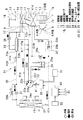
図1は、本発明を電気自動車用空調装置に適用した第1実施形態で、空調ユニット1は電気自動車の車室内に設置されるもので、その空調ダクト2は、車室内に空調空気を導く空調通路を構成するものである。この空調ダクト2の一端側に内外気を吸入する吸入口3、4、5が設けられている。内気吸入口4と外気吸入口5は、内外気切替ドア6により切替開閉される。
【0028】
上記吸入口3〜5に隣接して、空調ダクト2内に空気を送風する送風機7が設置されており、この送風機7は図示しないモ−タとこのモータにより駆動されるファン7a、7bにより構成される。
一方、空調ダクト2の他端側には車室内へ通ずる複数の吹出口、すなわち車室内乗員の足元部に向かって空調空気を吹き出すフット吹出口8、車室内乗員の上半身に向かって空調空気を吹き出すフェイス吹出口9および車両フロントガラスの内面に空調空気を吹き出すデフロスタ吹出口10が形成されている。
【0029】
また、送風機7よりも空気下流側における空調ダクト2内には冷房用蒸発器11が設けられている。この冷房用蒸発器11は、冷凍サイクル21の一部を構成する室内側熱交換器であり、後述する冷房運転および除湿運転モード時に、内部を流れる冷媒の吸熱作用によって、空調ダクト2内の空気を除湿、冷却する冷却器として機能する。
【0030】
また、冷房用蒸発器11よりも空気下流側における空調ダクト2内には暖房用凝縮器12が設けられている。この暖房用凝縮器12は、冷凍サイクル21の一部を構成する室内側熱交換器であり、後述する暖房運転および除湿運転モード時に、内部を流れる冷媒の放熱作用によって、空調ダクト2内の空気を加熱する加熱器として機能する。
【0031】
また、空調ダクト2内の空気流路は、仕切り壁13によりフット吹出口8側の第1空気流路14と、フェイス吹出口9およびデフロスタ吹出口10側の第2空気流路15とに仕切られている。この空気流路14、15の2分割は冬季の暖房時に次の内外気2層モードを実施するためである。すなわち、冬季暖房時にフット吹出口8側の第1空気流路14には内気吸入口3から温度の高い内気を吸入して足元へ温度を吹き出すことにより暖房負荷を軽減すると同時に、デフロスタ吹出口10側の第2空気流路15には外気吸入口5から湿度の低い外気を吸入して、フロントウインドの曇りを確実に防止する内外気2層モードを実施するために、空気流路14、15の2分割を行っている。
【0032】
ドア16、17は凝縮器12を通る空気通路と凝縮器12をバイパスするバイパス通路12aとを切り替える通路切替ドアであり、一方のドア17は空気流路14、15の仕切り部材の役割を兼ねている。また、18は空気流路14、15の下流側に配置されたドアで、空気流路14、15の仕切り作用と空気流路14、15の連通状態とを切り替えるドアである。なお、前記した各吹出口8、9、10は図示しない吹出口切替ドアにより開閉される。
【0033】
ところで、上記冷凍サイクル21は、冷房用の蒸発器11と暖房用の凝縮器12とで冷房および暖房を行うヒートポンプ式冷凍サイクルとして構成されており、蒸発器11と凝縮器12の他に以下の機器を備えている。すなわち、冷媒圧縮機22、気液2相の中間圧冷媒を高圧冷媒と熱交換してガス化する冷媒−冷媒熱交換器23、室外熱交換器24、サイクル低圧冷媒(圧縮機吸入冷媒)の気液を分離して余剰液冷媒を溜めておくアキュムレータ(気液分離器)25、凝縮器12通過後の高圧冷媒の一部をバイパスさせて中間圧に減圧する第1減圧装置26、冷媒−冷媒熱交換器23の出口の高圧冷媒を暖房時に低圧まで減圧する第2減圧装置27、冷房時に室外熱交換器24からの凝縮後の高圧冷媒を低圧まで減圧する第3減圧装置29、および冷房、暖房での冷媒流れを切り替える電磁弁(冷媒経路切替手段)28a、28bが冷凍サイクル21に備えられている。
【0034】
なお、室外熱交換器24は電気自動車の車室外に設置され、電動室外ファン24aにより送風される外気と熱交換するようになっている。また、上記冷媒圧縮機22は、電動式圧縮機であって、図示しない交流モータを一体に密封ケース内に内蔵し、このモータにより駆動されて冷媒の吸入、圧縮、吐出を行う。この冷媒圧縮機22の交流モータにはインバータ30により交流電圧が印加され、このインバータ30により交流電圧の周波数を調整することによってモータ回転速度を連続的に変化させるようになっている。従って、インバータ30は圧縮機22の回転数調整手段をなすものであり、このインバータ30には、車載バッテリ31からの直流電圧が印加される。インバータ30は空調用制御装置40によって通電制御される。
【0035】
冷媒圧縮機22には圧縮した冷媒を吐出する吐出ポート22a、サイクル低圧側の冷媒を吸入する吸入ポート22b、および中間圧のガス冷媒をインジェクションするガスインジェクションポート22cが備えられている。このガスインジェクションポート22cは、ガスインジェクション通路22dを介して冷媒−冷媒熱交換器23に連通している。
【0036】
第1減圧装置26および第2減圧装置27は電気的に弁開度が調整される電気式膨張弁からなり、この電気式膨張弁は例えば、ステップモータのような電気駆動手段を有し、この電気駆動手段により弁体の変位量を調整して、この弁体により冷媒絞り通路の開度を調整するものである。また、第3減圧装置29は固定絞り手段であり、図示の例では、上流側のキャピラリチューブ29aと下流側のオリフィス29bとの組み合わせからなる。
【0037】
アキュムレータ25はU状の冷媒出口管25aを有しており、余剰液冷媒を底部側に溜めてガス冷媒をU状の冷媒出口管25aの上端開口部から吸入することにより圧縮機22への液バックを防止する。また、同時に、アキュムレータ25のU状の冷媒出口管25aの底部に設けた小径のオイル戻し穴(図示せず)から、オイルが一部溶け込んだ液冷媒を吸入してガス冷媒に混合することより、圧縮機22へのオイル戻り性を確保するように構成されている。
【0038】
また、冷媒−冷媒熱交換器23と室外熱交換器24を接続する高圧側の冷媒配管32には、冷媒−冷媒熱交換器23出口の高圧冷媒の温度および圧力を検出するための冷媒温度センサ41aと高圧センサ41bが設置されている。このセンサ41a、41bの出力信号は空調用制御装置40に入力され、第2減圧装置27の開度を制御することで冷媒−冷媒熱交換器23出口の高圧冷媒のサブクール(過冷却度)を制御する。
【0039】
また、前記したインジェクション通路22dには、第1減圧装置26で減圧された中間圧冷媒の温度および圧力を検出する中間圧冷媒温度センサ41f、中間圧センサ41gが設置されている。このセンサ41f、41gの出力信号は空調用制御装置40に入力され、第1減圧装置26の開度を制御することで、冷媒−冷媒熱交換器出口の中間圧冷媒のスーパヒート(過熱度)を制御する。
【0040】
空調用制御装置40はマイクロコンピュータとその周辺回路にて構成されるもので、空調用制御装置40には、上記センサ41a、41b、41f、41gの他に、外気温センサ41c、蒸発器直後の空気温度を検出する蒸発器温度センサ41d、圧縮機22の吐出ガス温度を検出する吐出温度センサ41e、室外熱交換器24出口の冷媒温度センサ41h、インバータ30の電流センサ41i等のセンサ群41からセンサ信号が入力されるようになっている。
【0041】
また、空調用制御装置40には、空調用コントロールパネル50(図2参照)から乗員(ユーザ)により操作される各レバーの設定状況に応じた信号も入力されるようになっている。
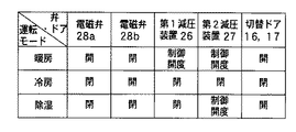
なお、図1にはインバータ30と空調用制御装置40との間の電気的接続のみを示し、他の機器と空調用制御装置40との電気的接続を図示していないが、第1、第2減圧装置26、27、電磁弁28a、28b、ドア6、16、17、18、図示しない吹出口切替ドア、送風機7、および室外ファン24aの作動も制御装置40により制御される。電磁弁28a、28bは、制御装置40により開閉制御されて冷媒循環経路を冷房、暖房、除湿の各運転モードに対応して切り替える。
【0042】
図2に示す空調コントロールパネル50には、乗員により手動操作される以下の操作部材が設けられている。51は車室内への吹出空気の温度の目標値を設定する温度コントロールレバーで、本例では、電動式圧縮機22の回転数調整の目標値を設定するように構成されている。
また、温度コントロールレバー51の操作位置により設定される目標値に対し、電磁弁28a、28bおよび通路切替ドア16、17の開閉を制御し、冷凍サイクルの運転モードの切替および凝縮器12での熱交換量を制御する。
【0043】
各運転モードの切替は例えば図3に示すようにレバー51を左から右に移動させることにより冷房モード、除湿モード、暖房モードを順次設定する。また、図4、5、6に示すように温度コントロールレバー51の操作位置の移動により、冷房時には目標蒸発器吹出温度が設定され、除湿時および暖房時には目標高圧圧力が設定されるようになっている。
【0044】
温度コントロールレバー51の操作位置信号は制御装置40に入力され、そして制御装置40は、センサ群41により検出される実際の蒸発器吹出空気温度または高圧圧力が上記目標値と一致するように圧縮機22の回転数を制御して、吹出空気温度を制御する。
52は送風機7の速度切替レバー、53は圧縮機22の運転を断続するエアコンスイッチ、54は吹出口8、9、10の切替ドア(図示せず)を開閉する空調吹出モード切替レバー、55は内外切替ドア6を開閉する内外気切替レバーである。
【0045】
一方、前記した冷媒−冷媒熱交換器23は例えば図7に示すように、内部通路23aと外部通路23bとを同心状に形成した二重通路構造の円筒形状になっている。内部通路23aは中心部に位置して室外熱交換器24へ向かう主流の冷媒(高圧冷媒)が流れる。これに対し、外部通路23bは、内部通路23aの外周側の円周方向に並列配置された多数の小通路から形成されており、外部通路23bにはインジェクション通路22dを通りインジェクションポート22cに導かれる中間圧冷媒が流れる。
【0046】
ここで、内部通路23aおよび外部通路23bを形成する管状体23cはアルミニウム等の熱伝導性に優れた金属にて成形(例えば、押出し成形)され、かつ、管状体23cの外表面には断熱材23dが固着されているので、内部通路23a内の高圧冷媒と外部通路23b内の中間圧冷媒との相互間のみで良好に熱交換を行うことができる。
【0047】
この冷媒−冷媒熱交換器23は、ガスインジェクションを必要としないときには、第1減圧装置26を全閉することにより、内部通路23aのみに高圧冷媒が流れるので、高圧側配管32の一部として使われる。
次に、上記構成において本第1実施形態の作動を説明する。エアコンスイッチ53が投入されると、その信号が制御装置40に投入され、圧縮機22を起動する。この状態にて温度コントロールレバー51が図3のPH2からPH1の位置にあると、制御装置40は暖房モードと判定して電磁弁28a、28bおよび通路切替ドア16、17を図8の暖房運転時の状態に制御する。
【0048】
この暖房モード時における冷媒流れを図1のサイクルにて説明すると、圧縮機22から吐出された高温高圧の過熱ガス冷媒は、まず、室内に設定された凝縮器12に流入し、ここで送風機7により送風される空気と熱交換(放熱)し、ガス冷媒が凝縮する。ガス冷媒の凝縮により加熱された温風は主にフット吹出口8より車室内へ吹き出され、車室内の暖房を行う。
【0049】
凝縮器12から流出した高圧の二相冷媒の一部はインジェクション通路22dにバイパスされ、ここで第1減圧装置26に流入し、中間圧PMまで減圧される。中間圧PMまで減圧された二相冷媒は冷媒−冷媒熱交換器23の外部通路23bを通り、内部通路23aを通る室内凝縮器12出口の高圧冷媒と熱交換(吸熱)することでガス化されインジェクションポート22cに流入する。
【0050】
一方、冷媒−冷媒熱交換器23の内部通路23aを通る高圧冷媒は外部通路23bを通る冷媒と熱交換(放熱)し、過冷却される。暖房時には冷房用電磁弁28bが閉じているため、この過冷却された高圧冷媒は第2減圧装置27に流入し、第2減圧装置27により低圧PLまで減圧され室外熱交換器24に流入する。そして、この低圧冷媒が室外熱交換器24を通る際に室外ファン24aの送風空気(外気)から吸熱して蒸発する。
【0051】
室外熱交換器24で蒸発したガス冷媒は、暖房用電磁弁28aを通過してアキュムレータ25に流入し、暖房負荷の変動により生じる液冷媒はアキュムレータ25内に溜められる。アキュムレータ25ではそのU状の冷媒出口管25aの上端開口部からガス冷媒を吸入するとともに、U状の冷媒出口管25aの底部に設けたオイル戻し穴(図示せず)から、オイルが一部溶け込んだ液冷媒を吸入してガス冷媒に混合し、このガス冷媒を冷媒吸入通路22fから圧縮機22の吸入ポート22bに吸入させる。これにより、中間期の暖房低負荷時のように冷媒流量が少ない条件のもとでも、圧縮機22へ確実にオイルを戻すことができる。
【0052】
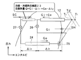
図9は上記した暖房運転時における冷凍サイクルの冷媒の状態を示すモリエル線図であり、図1中の黒色矢印は暖房運転時の冷媒流れ経路を示す。
第1減圧装置(電気式膨張弁)26の開度は、中間圧冷媒の温度センサ41fおよひ圧力センサ41gの検出信号に基づいて制御装置40により制御されて、圧縮機22のインジェクションポート22cに流入するガスインジェクション冷媒のスーパーヒートSHが所定量になるように冷媒流量を制御する。すなわち、ガスインジェクション冷媒のスーパーヒートSHが大きくなれば、第1減圧装置(電気式膨張弁)26の開度を増大し、逆にスーパーヒートSHが小さくなれば、第1減圧装置(電気式膨張弁)26の開度を減少させる。
【0053】
また、第2減圧装置27の開度は制御装置40により制御されて、冷媒−冷媒熱交換器23の内部通路23aを出た高圧冷媒のサブクールSCが所定量になるように冷媒−冷媒熱交換器23での交換熱量を制御する。すなわち、高圧冷媒のサブクールSCが大きくなれば、第2減圧装置27の開度を増大して高圧を低下させてサブクールSCを減少させる。逆に、高圧冷媒のサブクールSCが小さくなれば、第2減圧装置27の開度を減少して高圧を上昇させて、サブクールSCを増加させる。
【0054】
なお、図9において、Giはインジェクション通路22dからインジェクションポート22cにガスインジェクションされる冷媒流量、Geは室外熱交換器(暖房時の蒸発器)24を通して圧縮機22に吸入される冷媒流量、Δi1 は冷媒−冷媒熱交換器23で吸熱するガスインジェクション側の中間圧冷媒のエンタルピ差で、Δi2 は冷媒−冷媒熱交換器23で放熱して、第2減圧装置27に向かう高圧冷媒のエンタルピ差である。
【0055】
また、通路切替ドア16、17は凝縮器12側の空気通路を開いてバイパス通路12aを全閉し、圧縮機22から吐出された高温高圧冷媒と送風機7により送風された空気とを凝縮器12にて熱交換させる。
次に、温度コントロールレバー51が図3のPC1からPC2の位置にあると、制御装置40は冷房モードと判定して電磁弁28a、28bおよびエアミックスドア16、17を図8の冷房運転の状態に制御する。
【0056】
この冷房モードにおける冷媒流れを図1のサイクルにて説明すると、圧縮機22から吐出された高温高圧の過熱ガス冷媒は、まず、室内に設定された凝縮器12に流入するが、通路切替ドア16、17が凝縮器12側の空気通路を全閉するため、凝縮器12でガス冷媒は送風機7により送風される空気と熱交換(放熱)しない。送風機7の送風空気は全量、バイパス通路12aを流れる。そのため、圧縮機22からの吐出ガス冷媒は、高温高圧の過熱状態のまま、冷媒−冷媒熱交換器23の内部通路23aに流入する。
【0057】
このとき、圧縮機22へのインジェクション通路22dに設置されている第1減圧装置(電気式膨張弁)26が全閉状態に制御されているため、圧縮機22からの吐出ガス冷媒はインジェクション通路22dに分岐されることなく、その全量が冷媒−冷媒熱交換器23の内部通路23aに流入する。しかし、外部通路23bに中間圧の低温冷媒が流れないため、内部通路22aを通る冷媒は冷却されず高温高圧の過熱ガス冷媒のまま冷媒−冷媒熱交換器23から流れ出し、開弁状態にある冷房用電磁弁28bを通り室外熱交換器24に流入する。
【0058】
この室外熱交換器24では、室外ファン24aの送風空気(外気)と高圧ガス冷媒とが熱交換(放熱)して冷媒が凝縮する。そして、室外熱交換器24で凝縮した冷媒は、暖房用電磁弁28aの閉弁により第3減圧装置29を通過し、ここで低圧PLまで減圧された後、蒸発器11に流入する。
この蒸発器11にて冷媒が送風機7の送風空気から吸熱して蒸発する。蒸発器11にて吸熱され冷却された冷風は、上記したように下流側の室内凝縮器12は通過せず、そのバイパス通路12aを冷風のまま通過して、主にフェイス吹出口9から車室内へ吹き出して車室内を冷房する。
【0059】
一方、蒸発器11で蒸発したガス冷媒はアキュムレータ25に流入し、このアキュムレータ25からガス冷媒は冷媒吸入通路22fを通過して圧縮機22の吸入ポート22bに吸入される。図1の白抜き矢印は冷房運転時の冷媒流れ経路を示す。
最後に、温度コントロールレバー51が図3のPD1からPD2の位置にあると、制御装置40は除湿モードと判定して電磁弁28a、28bおよび通路切替ドア16、17を図8の除湿運転時の状態に制御する。
【0060】
この除湿モードにおける冷媒流れを図1のサイクルにて説明すると、圧縮機22から吐出された高温高圧の過熱ガス冷媒は、通路切替ドア16、17の開により室内に設定された凝縮器12に流入し、ここで送風機7の送風空気と熱交換(放熱)し、ガス冷媒が凝縮する。
このとき、圧縮機22へのインジェクション通路22dに設定されている第1減圧装置26が全閉状態に制御され、冷媒がインジェクション通路22dを流れないため、凝縮器12で凝縮した高圧冷媒の全量が冷媒−冷媒熱交換器23の内部通路23aを通過する。このとき、内部通路23aを通過する冷媒は冷却されず、室内凝縮器12を出たときの状態のまま、冷媒−冷媒熱交換器23を通過する。このとき、冷房用電磁弁28bの閉弁により、高圧冷媒は第2減圧装置27に流入し、この第2減圧装置27により中間圧に減圧され室外熱交換器24に流入する。
【0061】
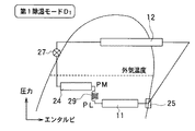
ここで、第2減圧装置27により作られる中間圧は、除湿モードにおいて高い吹出温度が必要な第1除湿モードD1 では、外気温度に対する冷媒の飽和圧力より低く設定することにより、図10のモリエル線図に示すように室外熱交換器24を蒸発器として作用させて吸熱側に設定できる。すなわち、第2減圧装置27の開度を小さくして減圧量を大きくすることにより中間圧が低く設定される。
【0062】
そして、室外熱交換器24を流れ出た中間圧冷媒は、暖房用電磁弁28aの閉弁により第3減圧装置29に流入し、低圧PLまで減圧される。この減圧された低圧冷媒は、蒸発器11に流入し、送風機7の送風空気から吸熱して蒸発した後、アキュムレータ25に流入する。アキュムレータ25からガス冷媒は冷媒吸入通路22fを通過して圧縮機22の吸入ポート22bに吸入される。図1の斜線付き矢印は除湿運転時の冷媒流れ経路を示す。
【0063】
除湿モードでは、室内空調ユニット1内に設定された蒸発器11および凝縮器12にともに冷媒が流れて、送風機7の送風空気はまず蒸発器11で冷却、除湿され、その後に凝縮器12にて再加熱され、温風となる。この温風は主にデフ吹出口10より車室内へ吹き出され、窓ガラスの曇り止めを行うとともに、車室内を除湿暖房する。
【0064】
ところで、除湿モードの中で、高い吹出温度が必要な第2除湿モードD1 では、図10のモリエル線図から理解されるように、圧縮機22の動力L、室外熱交換器24の吸熱量Qeh、および室内蒸発器11での吸熱量Qeの総和が室内凝縮器12から放熱(放熱量Qc)できるため、目的の高い吹出温度を作り出すことができる。この場合、室内凝縮器12からの放熱量Qcは下記数式1で表すことができる。
【0065】
【数1】
Qc=L+Qeh+Qe
一方、除湿モードの中で、低い吹出温度が必要な第1除湿モードD2 では、第2減圧装置27により作られる中間圧を、外気温度に対する冷媒の飽和圧力よりも高く設定することにより、図11のモリエル線図に示すように室外熱交換器24を凝縮器として作用させて放熱側に設定できる。すなわち、第2減圧装置27の弁開度を大きくして減圧量を小さくすることにより中間圧が高く設定される。
【0066】
このように室外熱交換器24が凝縮器となり放熱側として作用するため、圧縮機22の動力Lおよび室内蒸発器11での吸熱量Qeの合計と、室外熱交換器24での放熱量Qehと室内凝縮器11での放熱量Qcの合計とが等しくなる。従って、室内凝縮器11での放熱量Qcは下記の数式2で表すことができ、第1除湿モードD1 の場合より減少するので、目的とする低い吹出温度を作り出すことができる。
【0067】
【数2】
Qc=L+(−Qeh)+Qe
このように、第2減圧装置27の弁開度の調整により中間圧を制御することにより除湿時の吹出温度をリニアに制御できる。
次に、上記した実施形態による効果について説明する。
【0068】
▲1▼暖房能力の向上
従来のヒートポンプシステムでは、暖房時に外気温度が低くなると、吸入圧力が低下して冷媒比容積が大きくなるため、圧縮機22で吸入する冷媒循環量G1が減少し、暖房能力が低下する。また、吸入圧力の低下により圧縮比が大きくなるため、圧縮機22の吐出冷媒温度Tdが図9のT1 点まで上昇する。このため、圧縮機22保護のため、圧縮機22を最大能力(最大回転数)で使用できない。
【0069】
これに対して、本実施形態においては、室内凝縮器12の出口冷媒の一部を減圧し、冷媒−冷媒熱交換器23にて熱交換し、ガス化させ、このガス冷媒をガスインジェクション通路22dを通して圧縮機22の圧縮過程途中に戻す(ガスインジェクション)ため、圧縮機22で吸入する冷媒循環量Geに、ガスインジェクションされる冷媒量Giが加わって、圧縮仕事がなされることになる。これにより、圧縮仕事量が増加し、凝縮器12での冷媒放熱量が増加するので、暖房能力を向上できる。
【0070】
また、同時に、圧縮機22の圧縮過程の途中に中間圧のガス冷媒がインジェクションされるため、途中まで圧縮加熱されたガス冷媒が中間圧ガス冷媒により冷却され、吐出冷媒温度Tdが図9のT2 点まで低下する。このため、圧縮機22を最大能力(最大回転数)で使用することが可能となる。以上により、低外気温時における暖房能力を効果的に向上できる。
【0071】
▲2▼暖房低負荷時(圧縮機低回転数域)でのオイル戻り性の改善効果
圧縮機吸入側の低圧冷媒が温度膨張弁により過熱度制御されている従来技術では、例えば、中間期のような暖房低負荷時でのサイクルバランスを考えると、圧縮機回転数の低下により室外熱交換器を通過する低圧冷媒の流量(流速)の低下により室外熱交換器にオイルが溜まってしまい、圧縮機にオイルが戻りにくくなる場合がある。しかし、本実施形態によると、冷媒−冷媒熱交換器23の採用により、ガスインジョクションのための気液分離器を必要としないため、圧縮機吸入側にアキュムレータ25を設けて、このアキュムレータ25により圧縮機吸入冷媒の過熱度SH=0に制御できる。そして、アキュムレータ25の出口管25aのオイル戻し穴から一定量のオイルを含む液冷媒を圧縮機22に戻すことができるので、圧縮機22へのオイル戻り性を暖房低負荷時でも良好に維持することができる。
【0072】
▲3▼サイクル冷媒循環経路の簡素化
冷房モード時に通路切替ドア16、17により凝縮器12への空気流れを遮断してバイパス通路12aを空気が通過するようにしているため、凝縮器12は高圧冷媒が流れる冷媒通路の一部となる。そのため、暖房、冷房、除湿の全モードを通じて、凝縮器12に冷媒が流れたままとなるので、圧縮機22の吐出ガス冷媒を常に凝縮器12を通して室外熱交換器24へ向かう一方向に流すことができる。その結果、冷媒流れ方向逆転のための四方弁の廃止、あるいは、冷媒流れ経路切替用の逆止弁、電磁弁等の弁装置の数を低減することが可能となり、冷媒配管構成を簡素化できる。
【0073】
(第2実施形態)
図12は第2実施形態であり、第1実施形態ではガスインジェクション通路22dに設ける第1減圧装置26を電気式膨張弁により構成したが、第2実施形態では、第1減圧装置26として、ガスインジェクション通路22dの中間圧冷媒温度を感知する感温筒26aを備えた温度式膨張弁を用いている。そして、この第1減圧装置(温度式膨張弁)26の上流側に電磁弁(第3電気的開閉手段)28cを配置している。この電磁弁28cは、冷房モードおよび除湿モードには制御装置40の出力により閉弁され、暖房モードに開弁される。
【0074】
従って、暖房モード時には、温度式膨張弁からなる第1減圧装置26により高圧冷媒が中間圧に減圧されるとともに、この中間圧冷媒の過熱度が温度式膨張弁により所定値に調整される。他の点は第1実施形態と同じである。
(第3実施形態)
図13、図14は第3実施形態であり、第1、第2実施形態では、圧縮機22の吐出ガス冷媒を暖房、冷房、除湿の全モードにおいて常に室内凝縮器12に流入させる冷媒通路構成としているが、第3実施形態では圧縮機22の吐出ポート22aと室内凝縮器12との間に、制御装置40の出力により切り替えられる四方弁33を設置している。
【0075】
図13は暖房および除湿モードにおける四方弁33の操作位置を示しており、図13の黒色矢印は暖房モードの冷媒流れの経路で、斜線付き矢印は除湿モードの冷媒流れの経路を示している。圧縮機22の吐出ポート22aが四方弁33を介して室内凝縮器12に連通する。なお、室外熱交換器24の冷媒入口部が四方弁33を介してアキュムレータ25の入口部に接続されるが、この室外熱交換器24の冷媒入口部からアキュムレータ25の入口部への冷媒流れは逆止弁34により阻止される。
【0076】
これに対して、図14の白抜き矢印は冷房モードの冷媒流れの経路であり、圧縮機22の吐出ポート22aが四方弁33および逆止弁34を介して室外熱交換器24の冷媒入口部に接続されるので、冷房モード時には圧縮機22の吐出ガス冷媒が直接室外熱交換器24に向かって流れる。従って、冷房モード時に圧縮機22の吐出ガス冷媒が室内凝縮器12に流入することはない。
【0077】
このため、空調ユニット1内の通路切替ドア16、17は室内凝縮器12への空気通路を全閉する位置に限らず、室内凝縮器12への空気通路とバイパス通路12aを両方とも開放する位置に操作してもよい。
(第4実施形態)
図15は第4実施形態であり、第1実施形態では、第2減圧装置27に電磁弁28bを並列接続しているが、第4実施形態では凝縮器12の出口側(冷媒−冷媒熱交換器23の上流側)の部位から室外熱交換器24の入口側(第2減圧装置27の下流側)に直接至るバイパス通路60を設け、このバイパス通路60に電磁弁(請求項5の第1電気的開閉手段)28bを挿入している。
【0078】
第4実施形態によると、冷房モード時に電磁弁28bを開くと、冷媒−冷媒熱交換器23の上流側から高圧冷媒を冷媒−冷媒熱交換器23および第2減圧装置27をバイパスして、直接、室外熱交換器24に流入させることができる。
従って、冷房モード時に第1実施形態では発生していた冷媒−冷媒熱交換器23での圧力損失を第4実施形態では解消することができ、この圧力損失の低減分だけ、冷房モード時のサイクル効率を向上できる。また、冷媒流量が多くなる冷房モード時に高圧冷媒が冷媒−冷媒熱交換器23をバイパスして流れるので、冷媒−冷媒熱交換器23を冷房モード時の圧力損失を考慮せずに設計することができ、そのため、冷媒−冷媒熱交換器23の小型、軽量化が可能であり、冷媒−冷媒熱交換器23の製造コストを低減できる。
【0079】
第4実施形態において、暖房および除湿モード時の作動は第1実施形態と同じであるので、説明は省略する。また、第4実施形態では第1減圧装置26が設置されるバイパス通路61からバイパス通路60を分岐させる構成としているが、凝縮器12の出口を冷媒−冷媒熱交換器23の入口に連結する主流路62からバイパス通路60を分岐させてもよいことはもちろんである。
【0080】
(第5実施形態)
図16は第5実施形態であり、暖房モード時にガスインジェクション通路22dに溜まった液冷媒をアキュムレータ25の上流側に流入させて、圧縮機22への液戻りを防止するようにしたものである。
このため、図16に示すように、ガスインジェクションポート22cの上流側に位置するガスインジェクション通路22dとアキュムレータ25の上流側とを直接接続するバイパス通路63を設けるとともに、このバイパス通路63に電磁弁(請求項6の第2電気的開閉手段)28dを挿入している。
【0081】
第5実施形態では、圧縮機22のポート径(ポート開口面積)に比較して電磁弁28dの弁口径(弁開口面積)を大きくすることにより、電磁弁28dの開弁時にガスインジェクション通路22dの冷媒をバイパス通路63を通過してアキュムレータ25に流入させるようにしている。しかし、ガスインジェクションポート径<電磁弁口径の関係を設定できないときは、バイパス通路63の分岐点63aとガスインジェクションポート22cとの間に電磁弁を追加設置し、この電磁弁を上記電磁弁28dの開弁時に閉弁させればよい。
【0082】
次に、第5実施形態の作動を図17に基づいて説明すると、図17の制御ルーチンは空調装置の起動によりスタートし、ステップS100にて、図2の温度コントロールレバー51の操作位置に基づいて運転モードを図3のごとく決定する。そして、ステップS101にて運転モードが暖房モードであるか判定し、暖房モードであるときはステップS102に進み、暖房モード起動後の経過時間tが予め設定した設定時間t0を越えたか判定する。
【0083】
ここで、経過時間tが設定時間t0に到達していないときはステップS103に進み、電磁弁28dを開弁する。そして、経過時間tが設定時間t0を越えると、ステップS104に進み、電磁弁28dを閉弁する。
上記設定時間t0は、ガスインジェクション通路22dに寝込んだ液冷媒をアキュムレータ25の上流側に排出するのに必要な時間を設定している。従って、暖房モード起動後、上記設定時間t0の間、電磁弁28dを開弁することにより、ガスインジェクション通路22dの寝込み液冷媒をバイパス通路63を通過してアキュムレータ25に流入させることができる。
【0084】
そのため、暖房モード起動時にガスインジェクション通路22dでの寝込み液冷媒に起因する圧縮機22への液戻りを未然に防止できる。これにより、圧縮機22の液圧縮による故障の発生を防止して、圧縮機22の信頼性を向上できるとともに、暖房起動時における液戻りによるトルク上昇を防止して、サイクルを効率的に作動させることができる。
【0085】
そして、ステップS103またはステップS104の次にステップS105に進み、暖房モード時の制御を行う。すなわち、第1減圧装置26の開度等を図8の説明に従って制御する。
また、ステップS101にて暖房モードでないと判定されたとき、すなわち、冷房モードまたは除湿モードであるときはステップS106に進み、冷房モードまたは除湿モードの制御を行う。すなわち、第2減圧装置27の開度等を図8の説明に従って制御する。
【0086】
なお、上述の説明では暖房モード起動後、予め設定した設定時間t0の間、電磁弁28dを開弁することにより、ガスインジェクション通路22dの寝込み液冷媒をバイパス通路63を通過してアキュムレータ25に流入させているが、設定時間t0を設定せずに、以下のような別の手段を用いて電磁弁28dを開閉制御してもよい。
【0087】
例えば、ガスインジェクション通路22dに配置された中間圧冷媒の温度センサ41f、圧力センサ41gにより検出可能な中間圧冷媒の過熱度は暖房モード起動時には通常、0の状態にあり、そして、起動後、冷媒−冷媒熱交換器23における熱交換が進行することにより、中間圧冷媒の過熱度が増大していく。そこで、暖房モード起動後、中間圧冷媒の過熱度が所定値に増大するまでの間、電磁弁28dを開弁し、中間圧冷媒の過熱度が所定値に増大した後に、電磁弁28dを閉弁するようにしてもよい。
【0088】
また、別の手段として、暖房モード起動後、圧縮機22のトルク(=インバータ30の電流→電流センサ41iの検出値)、圧縮機22の回転数、サイクル高圧(高圧センサ41bの検出値)が所定値に増大するまでの間、電磁弁28dを開弁し、これら検出値が所定値に増大した後に、電磁弁28dを閉弁するようにしてもよい。
【0089】
(第6実施形態)
図18は第6実施形態であり、第4実施形態による、冷媒−冷媒熱交換器23をバイパスするバイパス通路60に電磁弁28bを設ける構成と、第5実施形態による、ガスインジェクション通路22dの寝込み液冷媒をアキュムレータ25の上流側に流入させるバイパス通路63に電磁弁28dを設ける構成とを組み合わせたものである。これにより、第4、第5実施形態による作用効果を合わせ奏することができる。
【0090】
(他の実施形態)
なお、第1実施形態にて説明した第1除湿モードD1 時にさらに吹出温度を高く設定したい場合は、暖房運転と同様に第1減圧装置26の開度を制御し、圧縮機22にガス冷媒をインジェクションするようにしてもよい。これによれば、圧縮機動力Lを増加させると同時に、第2減圧装置27入口の高圧冷媒のサブクールを大きくとることで、室内凝縮器12での放熱量を多くとることができるので、車室内への吹出温度をさらに高くすることができる。
【0091】
また、第1実施形態における作動説明では、暖房モード時に常に第1減圧装置26を所定開度に開いて、圧縮機22にガス冷媒をインジェクションしているが、車室内への吹出温度を高くしたい第1暖房モードH1 と、車室内への吹出温度を低くしたい第2暖房モードH2 とを設定し、第1暖房モードH1 では第1減圧装置26を開き、第2暖房モードH2 では第1減圧装置26を閉じて圧縮機22へのガスインジェクションを停止するようにしてもよい。
【0092】
また、第1減圧装置26として、第1実施形態の電気式膨張弁や第2実施形態の温度式膨張弁を使用せず、固定絞りを用い、この固定絞りに第2実施形態のように電磁弁(開閉手段)28cを組み合わせてもよい。
上述の各実施形態では、凝縮器12への空気流れとバイパス通路12aへの空気流れを切り替えるドア手段として、連動操作される2枚の板状の通路切替ドア16、17を用いているが、このドア手段として、1枚の板状ドア、さらにはフィルム状ドア等を用いてもよいことはもちろんである。
【図面の簡単な説明】
【図1】本発明の第1実施形態を示す冷凍サイクル図である。
【図2】第1実施形態で使用する空調制御パネルの正面図である。
【図3】図2の空調制御パネルにおける温度コントロールレバーの作動領域と運転モードとの特性図である。
【図4】同温度コントロールレバーの冷房領域の特性図である。
【図5】同温度コントロールレバーの除湿領域の特性図である。
【図6】同温度コントロールレバーの暖房領域の特性図である。
【図7】第1実施形態で使用する冷媒−冷媒熱交換器の具体例を示す断面図である。
【図8】第1実施形態で使用する弁・ドアの作動説明用の図表である。
【図9】第1実施形態における暖房モードの冷凍サイクルの作動を従来技術と比較して示すモリエル線図である。
【図10】第1実施形態における第1除湿モードD1 の冷凍サイクルの作動を示すモリエル線図である。
【図11】第1実施形態における第2除湿モードD2 の冷凍サイクルの作動を示すモリエル線図である。
【図12】本発明の第2実施形態を示す冷凍サイクル図である。
【図13】本発明の第3実施形態の暖房および除湿モードを示す冷凍サイクル図である。
【図14】本発明の第3実施形態の冷房モードを示す冷凍サイクル図である。
【図15】本発明の第4実施形態の冷房モードを示す冷凍サイクル図である。
【図16】本発明の第5実施形態の冷房モードを示す冷凍サイクル図である。
【図17】第5実施形態の作動を説明するフローチャートである。
【図18】本発明の第6実施形態の冷房モードを示す冷凍サイクル図である。
【符号の説明】
11…蒸発器、12…凝縮器、16、17…通路切替ドア、22…圧縮機、
22c…ガスインジェクションポート、22d…ガスインジェクション用通路、
23…冷媒−冷媒熱交換器、24…室外熱交換器、25…アキュムレータ、
26…第1減圧装置、27…第2減圧装置、29…第3減圧装置。[0001]
BACKGROUND OF THE INVENTION
The present invention relates to a heat pump type refrigeration cycle apparatus that improves heating capacity by gas injection, and is suitable for use in an air conditioner for an electric vehicle, for example.
[0002]
[Prior art]
Conventionally, in a vehicle such as an electric vehicle, the vehicle interior cannot be heated using engine waste heat (hot water) as a heat source. Therefore, a heat pump type refrigeration cycle device is provided and the vehicle interior is heated by the refrigerant condensation heat in the condenser. Like to heat up.
However, in a usage environment in which the outside air temperature drops below -10 ° C as in cold weather in winter, the amount of heat absorbed by the outdoor heat exchanger acting as an evaporator in the heat pump cycle is reduced, and the compressor suction Since the pressure is reduced, the refrigerant specific volume is increased, and the amount of refrigerant circulation is reduced, so that there is a problem that the heating capacity is lowered. For this reason, when used in cold regions, the heating capacity in the passenger compartment is insufficient.
[0003]
Therefore, in the present applicant, in JP-A-9-39550, during heating, the cycle high-pressure refrigerant is reduced to an intermediate pressure, and the intermediate-pressure refrigerant is separated into a gas refrigerant and a liquid refrigerant by a gas-liquid separator, A refrigeration cycle apparatus has been proposed that increases the heating capacity by increasing the amount of compression work of the compressor during heating by gas-injecting this intermediate-pressure gas refrigerant into the compressor.
[0004]
In this conventional apparatus, an evaporator of the refrigeration cycle is disposed upstream of the air passage of the indoor air conditioning unit, and a condenser of the refrigeration cycle is disposed downstream thereof, so that the dehumidifying operation is performed. I try to stop fogging.
[0005]
[Problems to be solved by the invention]
However, in the above-described conventional apparatus, during heating, the intermediate-pressure gas refrigerant separated by the gas-liquid separator is decompressed to a low pressure by the temperature type expansion valve, the low-pressure refrigerant is evaporated by the outdoor heat exchanger, and is supplied to the compressor. Although the degree of superheat of the suction refrigerant is adjusted by a temperature expansion valve, the flow rate (flow velocity) of the refrigerant flowing through the outdoor heat exchanger decreases due to a decrease in the compressor rotation speed during heating and low loads in the intermediate period. Oil in the refrigerant tends to accumulate in the heat exchanger. As a result, the oil return to the compressor may be deteriorated.
[0006]
Further, in the above-described conventional apparatus, the compressor discharge gas flows into the outdoor heat exchanger during cooling by the four-way valve arranged on the discharge side of the compressor, and the compressor discharge gas flows into the indoor condenser during heating. Since the flow direction of the refrigerant is switched so as to flow in, the refrigerant piping configuration of the cycle becomes complicated, and the number of parts increases.
The present invention has been made in view of the above points, and firstly, it is an object of the present invention to achieve both improvement in heating capacity by gas injection into the compressor and improvement in oil return to the compressor.
[0007]
A second object of the present invention is to achieve both improvement in heating capacity by gas injection into the compressor and simplification of the refrigerant passage configuration of the cycle.
[0008]
[Means for Solving the Problems]
In order to achieve the above object, in the first aspect of the present invention, the high-pressure gas refrigerant discharged from the discharge port (22a) of the compressor (22) flows into the air conditioning passage (2) to heat the air. An evaporator (11) in which a condenser (12) is installed, and in the air conditioning passage (2), a gas-liquid two-phase refrigerant on the low-pressure side of the refrigeration cycle flows into the upstream side of the condenser (12) to cool the air. )
In the heating mode, a part of the high-pressure refrigerant after passing through the condenser (12) is bypassed, and the part of the high-pressure refrigerant is reduced to an intermediate pressure by the first pressure reducing device (26), and after passing through the condenser (12). The remaining high-pressure refrigerant and the intermediate-pressure refrigerant that has passed through the first decompression device (26) are heat-exchanged by the refrigerant-refrigerant heat exchanger (23), and are cooled by the refrigerant-refrigerant heat exchanger (23). The refrigerant is decompressed to a low pressure by the second decompression device (27) in the heating mode, and the low-pressure refrigerant that has passed through the second decompression device (27) is exchanged with the outside air by the outdoor heat exchanger (24).
[0009]
An accumulator (25) is provided for separating the gas-liquid of the low-pressure refrigerant that has passed through the outdoor heat exchanger (24) in the heating mode, and for separating the gas-liquid of the low-pressure refrigerant that has passed through the evaporator (11) in the cooling mode. Liquid refrigerant and low-pressure gas refrigerant in which oil is dissolved from the accumulator (25) are caused to flow out toward the suction port (22b) of the compressor (22), and further by heat exchange in the refrigerant-refrigerant heat exchanger (23). The gasified intermediate pressure gas refrigerant is introduced into the gas injection port (22c) of the compressor (22) in the heating mode.
[0010]
According to this, the heating function is performed by the heat radiation action of the condenser (12) in the air conditioning passage (2), the cooling function is performed by the cooling action of the evaporator (11) in the air conditioning passage (2), and the upstream side. The dehumidifying and heating function can be exhibited by reheating the cooled and dehumidified air of the evaporator (11) with the condenser (12) on the downstream side.
Then, by using the intermediate pressure gas refrigerant gasified by heat exchange in the refrigerant-refrigerant heat exchanger (23), gas injection into the compressor (22) is performed, whereby the compressor (22) during heating is performed. Heating capacity can be increased by increasing the compression work.
[0011]
Moreover, since the gas-injection uses the refrigerant-refrigerant heat exchanger (23), a gas-liquid separator for separating the gas-liquid of the intermediate pressure refrigerant as in the prior art becomes unnecessary, and the compressor (22) is connected to the suction side. The cycle low-pressure refrigerant can be sent from the arranged accumulator (25) to the suction port (22b) of the compressor (22), and the liquid refrigerant in which oil is dissolved is surely mixed into the low-pressure gas refrigerant by the accumulator (25). be able to.
[0012]
As a result, the flow rate (flow velocity) of the refrigerant flowing through the outdoor heat exchanger (24) is reduced due to the decrease in the compressor rotation speed, and the oil in the refrigerant is likely to accumulate in the outdoor heat exchanger (24) even at a low heating load. The oil return property to the compressor (22) can be secured satisfactorily, and the durability of the compressor (22) can be improved.
Therefore, according to the first aspect of the present invention, in the refrigeration cycle apparatus capable of exhibiting the functions of heating, cooling, and dehumidification, the heating capacity is improved by gas injection into the compressor (22), and the compressor (22). It is possible to achieve both improved oil return performance.
[0013]
Next, the invention described in
That is, in the invention according to
In the air conditioning passage (2), door means (16, 17) for switching the air flow to the condenser (12) and the air flow to the bypass passage (12a) are installed, and condensation is performed in the air conditioning passage (2). An evaporator (11) is installed upstream of the condenser (12), a part of the high-pressure refrigerant after passing through the condenser (12) is bypassed, and the part of the high-pressure refrigerant is intermediated by the first pressure reducing device (26). The pressure is reduced to a pressure, and the remaining high-pressure refrigerant after passing through the condenser (12) and the intermediate-pressure refrigerant after passing through the first pressure reducing device (26) are heat-exchanged by the refrigerant-refrigerant heat exchanger (23).
[0014]
Further, a second decompression device (27) that decompresses the high-pressure refrigerant cooled by the refrigerant-refrigerant heat exchanger (23), and outdoor heat that is installed outside the air conditioning passage (2) and exchanges heat with the outside air. The refrigerant (24), the third decompressor (29) installed on the refrigerant flow inlet side of the evaporator (11), and the refrigerant of the refrigerant on the low pressure side of the refrigeration cycle are separated, and the liquid refrigerant in which the oil is dissolved And an accumulator (25) for allowing the low-pressure gas refrigerant to flow out toward the suction port (22b).
[0015]
(1) In the heating mode, the air flow to the bypass passage (12a) is blocked by the door means (16, 17) so that the air passes through the condenser (12).
Discharge port (22a) of compressor (22) → condenser (12) → refrigerant-refrigerant heat exchanger (23) → second decompression device (27) → outdoor heat exchanger (24) → accumulator (25) → compression As the refrigerant circulates through the path of the suction port (22b) of the compressor (22), the discharge port (22a) of the compressor (22) → the condenser (12) → the first pressure reducing device (26) → refrigerant-refrigerant heat exchange. The refrigerant circulates in the path of the gas injection port (22c) of the compressor (23) → the compressor (22),
(2) During the cooling mode, the air flow to the condenser (12) is blocked by the door means (16, 17) so that the air passes through the bypass passage (12a).
Discharge port (22a) of compressor (22) → condenser (12) → refrigerant passage including refrigerant-refrigerant heat exchanger (23) → outdoor heat exchanger (24) → third decompression device (29) → Refrigerant circulates in the path of the evaporator (11) → accumulator (25) → suction port (22b) of the compressor (22),
(3) In the dehumidifying mode, the air flow to the bypass passage (12a) is blocked by the door means (16, 17) so that the air passes through the condenser (12).
Discharge port (22a) of compressor (22) → condenser (12) → refrigerant-refrigerant heat exchanger (23) → second decompression device (27) → outdoor heat exchanger (24) → third decompression device (29 ) → Evaporator (11) → Accumulator (25) → Refrigerant circulates along the suction port (22b) of the compressor (22).
[0016]
According to this, each of the heating, cooling and dehumidifying functions can be satisfactorily performed by the refrigerant circulation paths (1), (2) and (3) above, and in the cooling mode, it is condensed by the door means (16, 17). Since the air flow to the condenser (12) is blocked and the air passes through the bypass passage (12a), the condenser (12) serves as a part of the refrigerant passage through which the high-pressure refrigerant flows. Become.
[0017]
Therefore, in the invention described in
[0018]
In particular, the invention according to
First dehumidification mode (D 1 ), The opening degree of the second pressure reducing device (27) is adjusted so that the outdoor heat exchanger (24) absorbs heat from the outside air and evaporates the refrigerant, and the second dehumidifying mode (D 2 ), The opening degree of the second pressure reducing device (27) is adjusted so that the outdoor heat exchanger (24) is on the heat radiation side for radiating heat to the outside air and condensing the refrigerant.
[0019]
According to this, by adjusting the opening degree of the second decompression device (27), the outdoor heat exchanger (24) can be switched between the heat absorption action as the refrigerant evaporator and the heat radiation action as the refrigerant condenser. Therefore, by switching between the heat absorption action and the heat radiation action, the amount of heat released from the indoor condenser (12) can be adjusted, and the indoor blown air temperature in the dehumidifying mode can be adjusted well.
[0020]
Moreover, in invention of Claim 4, in 1st heating mode (H) which wants to make the blowing air temperature from the blower outlet (8, 9, 10) of an air-conditioning channel | path (2) high in heating mode in
1st heating mode (H 1 ) Is set, the refrigerant is circulated through the route (1), and the second heating mode (H 2 ) Is stopped, a part of the high-pressure refrigerant that has passed through the condenser (12) is bypassed to flow to the first pressure reducing device (26) side and stopped, and then to the gas injection port (22c) of the compressor (22). The introduction of the intermediate pressure gas refrigerant is stopped.
[0021]
According to this, in the heating mode, the presence or absence of gas injection to the compressor (22) is switched, the amount of heat released from the indoor condenser (12) is adjusted, and the indoor blown air temperature in the heating mode is well adjusted. it can.
According to a fifth aspect of the invention, in any one of the second to fourth aspects, the refrigerant-refrigerant heat exchanger (23) and the second refrigerant passage part including the refrigerant-refrigerant heat exchanger (23) are provided. (2) A first bypass passage (60) is provided that bypasses the decompression device (27) and directly connects the outlet side of the condenser (12) to the inlet side of the outdoor heat exchanger (24). 60), the first electrical switching means (28b) is arranged, and the first electrical switching means (28b) is opened in the cooling mode.
[0022]
According to this, the refrigerant | coolant-refrigerant heat exchanger (23) can be bypassed at the time of a cooling mode, and the exit side refrigerant | coolant of a condenser (12) can be directly flowed in into the inlet side of an outdoor heat exchanger (24). Therefore, the pressure loss due to the refrigerant-refrigerant heat exchanger (23) can be eliminated during the cooling mode, and the cycle efficiency during the cooling mode can be improved.
According to a sixth aspect of the present invention, in any one of the first to fifth aspects, the second bypass passage (63) directly connects the upstream side of the gas injection port (22c) to the inlet side of the accumulator (25). The second electrical opening / closing means (28d) is disposed in the second bypass passage (63), and the second electrical opening / closing means (28d) is opened when the heating mode is activated. .
[0023]
According to this, since the liquid refrigerant stagnated in the upstream side passage of the gas injection port (22c) at the start of the heating mode can be caused to flow from the second bypass passage (63) to the accumulator (25), the compressor (22 The liquid return to) can be satisfactorily avoided.
In the seventh aspect of the invention, the first pressure reducing device (26) is configured to control the degree of superheat of the intermediate pressure gas refrigerant introduced into the gas injection port (22c) of the compressor (22). . Therefore, it is possible to always inject a gas refrigerant having an appropriate superheat degree into the compressor (22) regardless of cycle load fluctuations.
[0024]
Moreover, if the 1st pressure reduction device (26) is comprised by the electric expansion valve by which an opening degree is electrically adjusted like invention of
The first pressure reducing device (26) is constituted by a temperature type expansion valve as described in
[0025]
In the invention according to
The second pressure reducing device (27) can be constituted by an electric expansion valve whose opening degree is electrically adjusted as described in
[0026]
In addition, the code | symbol in the bracket | parenthesis of each said means shows a corresponding relationship with the specific means as described in embodiment mentioned later.
[0027]
DETAILED DESCRIPTION OF THE INVENTION
DESCRIPTION OF THE PREFERRED EMBODIMENTS Embodiments shown in the drawings will be described below.
(First embodiment)
FIG. 1 is a first embodiment in which the present invention is applied to an air conditioner for an electric vehicle. An
[0028]
A
On the other hand, at the other end of the
[0029]
In addition, a cooling
[0030]
Further, a
[0031]
In addition, the air flow path in the
[0032]
The
[0033]
By the way, the
[0034]
The
[0035]
The
[0036]
The first
[0037]
The
[0038]
A refrigerant temperature sensor for detecting the temperature and pressure of the high-pressure refrigerant at the outlet of the refrigerant-
[0039]
The
[0040]
The air-
[0041]
The air-
FIG. 1 shows only the electrical connection between the
[0042]
The air-
In addition, the opening and closing of the
[0043]
For example, as shown in FIG. 3, the operation mode is switched by sequentially setting the cooling mode, the dehumidifying mode, and the heating mode by moving the
[0044]
The operation position signal of the
52 is a speed switching lever of the
[0045]
On the other hand, the refrigerant-
[0046]
Here, the
[0047]
The refrigerant-
Next, the operation of the first embodiment in the above configuration will be described. When the
[0048]
The refrigerant flow in the heating mode will be described with reference to the cycle of FIG. 1. First, the high-temperature and high-pressure superheated gas refrigerant discharged from the
[0049]
Part of the high-pressure two-phase refrigerant flowing out of the
[0050]
On the other hand, the high-pressure refrigerant passing through the
[0051]
The gas refrigerant evaporated in the
[0052]
FIG. 9 is a Mollier diagram showing the state of the refrigerant in the refrigeration cycle during the heating operation described above, and the black arrows in FIG. 1 indicate the refrigerant flow path during the heating operation.
The opening degree of the first pressure reducing device (electric expansion valve) 26 is controlled by the
[0053]
In addition, the opening degree of the
[0054]
In FIG. 9, Gi is a refrigerant flow rate that is gas-injected from the
[0055]
In addition, the
Next, when the
[0056]
The refrigerant flow in the cooling mode will be described with reference to the cycle of FIG. 1. The high-temperature and high-pressure superheated gas refrigerant discharged from the
[0057]
At this time, since the first pressure reducing device (electric expansion valve) 26 installed in the
[0058]
In the
In the
[0059]
On the other hand, the gas refrigerant evaporated in the
Finally, when the
[0060]
The refrigerant flow in the dehumidifying mode will be described with reference to the cycle of FIG. 1. The high-temperature and high-pressure superheated gas refrigerant discharged from the
At this time, since the first
[0061]
Here, the intermediate pressure produced by the second
[0062]
Then, the intermediate pressure refrigerant that has flowed out of the
[0063]
In the dehumidifying mode, the refrigerant flows through both the
[0064]
By the way, in the dehumidifying mode, the second dehumidifying mode D which requires a high blowing temperature. 1 Then, as understood from the Mollier diagram of FIG. 10, the sum of the power L of the
[0065]
[Expression 1]
Qc = L + Qeh + Qe
On the other hand, in the dehumidification mode, the first dehumidification mode D that requires a low blowing temperature 2 Then, by setting the intermediate pressure produced by the
[0066]
Thus, since the
[0067]
[Expression 2]
Qc = L + (− Qeh) + Qe
Thus, by controlling the intermediate pressure by adjusting the valve opening degree of the second
Next, effects of the above-described embodiment will be described.
[0068]
▲ 1 ▼ Improvement of heating capacity
In the conventional heat pump system, when the outside air temperature decreases during heating, the suction pressure decreases and the refrigerant specific volume increases. Therefore, the refrigerant circulation amount G1 sucked by the
[0069]
On the other hand, in this embodiment, a part of the outlet refrigerant of the
[0070]
At the same time, since the intermediate-pressure gas refrigerant is injected in the middle of the compression process of the
[0071]
(2) Improvement of oil return when heating is under low load (compressor low speed range)
In the conventional technology in which the superheat degree of the low-pressure refrigerant on the compressor suction side is controlled by a temperature expansion valve, for example, when considering the cycle balance at the time of heating and low load such as an intermediate period, outdoor heat is reduced due to a decrease in the compressor rotation speed. Oil may accumulate in the outdoor heat exchanger due to a decrease in the flow rate (flow velocity) of the low-pressure refrigerant that passes through the exchanger, and it may be difficult for the oil to return to the compressor. However, according to the present embodiment, the adoption of the refrigerant-
[0072]
(3) Simplification of cycle refrigerant circulation path
Since the air flow to the
[0073]
(Second Embodiment)
FIG. 12 shows a second embodiment. In the first embodiment, the first
[0074]
Therefore, in the heating mode, the high pressure refrigerant is reduced to an intermediate pressure by the first
(Third embodiment)
FIGS. 13 and 14 show a third embodiment. In the first and second embodiments, the refrigerant passage configuration in which the refrigerant discharged from the
[0075]
FIG. 13 shows the operation position of the four-
[0076]
On the other hand, the white arrow in FIG. 14 is the refrigerant flow path in the cooling mode, and the
[0077]
For this reason, the
(Fourth embodiment)
FIG. 15 shows a fourth embodiment. In the first embodiment, an
[0078]
According to the fourth embodiment, when the
Therefore, the pressure loss in the refrigerant-
[0079]
In 4th Embodiment, since the action | operation at the time of heating and a dehumidification mode is the same as 1st Embodiment, description is abbreviate | omitted. In the fourth embodiment, the
[0080]
(Fifth embodiment)
FIG. 16 shows a fifth embodiment in which the liquid refrigerant accumulated in the
For this reason, as shown in FIG. 16, while providing the
[0081]
In the fifth embodiment, by increasing the valve diameter (valve opening area) of the
[0082]
Next, the operation of the fifth embodiment will be described with reference to FIG. 17. The control routine of FIG. 17 is started by the activation of the air conditioner, and in step S100, based on the operation position of the
[0083]
If the elapsed time t has not reached the set time t0, the process proceeds to step S103, and the
The set time t <b> 0 is set to a time required for discharging the liquid refrigerant stagnated in the
[0084]
Therefore, liquid return to the
[0085]
And after step S103 or step S104, it progresses to step S105 and performs control at the time of heating mode. That is, the opening degree and the like of the first
When it is determined in step S101 that the mode is not the heating mode, that is, in the cooling mode or the dehumidifying mode, the process proceeds to step S106, and the cooling mode or the dehumidifying mode is controlled. That is, the opening degree and the like of the
[0086]
In the above description, after the heating mode is activated, the
[0087]
For example, the degree of superheat of the intermediate pressure refrigerant that can be detected by the
[0088]
As another means, after the heating mode is started, the torque of the compressor 22 (= the current of the
[0089]
(Sixth embodiment)
FIG. 18 shows a sixth embodiment, in which the
[0090]
(Other embodiments)
The first dehumidification mode D described in the first embodiment. 1 In some cases, when it is desired to set the blowing temperature higher, the opening degree of the first
[0091]
In the description of the operation in the first embodiment, the
[0092]
Further, as the first
In each of the embodiments described above, two plate-shaped
[Brief description of the drawings]
FIG. 1 is a refrigeration cycle diagram showing a first embodiment of the present invention.
FIG. 2 is a front view of an air conditioning control panel used in the first embodiment.
3 is a characteristic diagram of an operation region and an operation mode of a temperature control lever in the air conditioning control panel of FIG.
FIG. 4 is a characteristic diagram of a cooling region of the temperature control lever.
FIG. 5 is a characteristic diagram of a dehumidifying region of the temperature control lever.
FIG. 6 is a characteristic diagram of a heating region of the temperature control lever.
FIG. 7 is a cross-sectional view showing a specific example of a refrigerant-refrigerant heat exchanger used in the first embodiment.
FIG. 8 is a chart for explaining operations of valves and doors used in the first embodiment.
FIG. 9 is a Mollier diagram showing the operation of the refrigeration cycle in the heating mode in the first embodiment in comparison with the prior art.
FIG. 10 shows a first dehumidifying mode D in the first embodiment. 1 It is a Mollier diagram which shows the action | operation of the refrigerating cycle.
FIG. 11 shows a second dehumidifying mode D in the first embodiment. 2 It is a Mollier diagram which shows the action | operation of the refrigerating cycle.
FIG. 12 is a refrigeration cycle diagram showing a second embodiment of the present invention.
FIG. 13 is a refrigeration cycle diagram showing a heating and dehumidifying mode according to a third embodiment of the present invention.
FIG. 14 is a refrigeration cycle diagram showing a cooling mode according to a third embodiment of the present invention.
FIG. 15 is a refrigeration cycle diagram showing a cooling mode according to a fourth embodiment of the present invention.
FIG. 16 is a refrigeration cycle diagram showing a cooling mode according to a fifth embodiment of the present invention.
FIG. 17 is a flowchart for explaining the operation of the fifth embodiment.
FIG. 18 is a refrigeration cycle diagram showing a cooling mode according to a sixth embodiment of the present invention.
[Explanation of symbols]
DESCRIPTION OF
22c: Gas injection port, 22d: Gas injection passage,
23 ... Refrigerant-refrigerant heat exchanger, 24 ... Outdoor heat exchanger, 25 ... Accumulator,
26 ... 1st decompression device, 27 ... 2nd decompression device, 29 ... 3rd decompression device.
Claims (11)
前記空調通路(2)に空気を送風する送風機(7)と、
圧縮した冷媒を吐出する吐出ポート(22a)、冷凍サイクル低圧側の冷媒を吸入する吸入ポート(22b)、および冷凍サイクル中間圧側のガス冷媒を導入するガスインジェクションポート(22c)を有する圧縮機(22)と、
前記空調通路(2)内に設置され、前記圧縮機(22)の吐出ポート(22a)から吐出された高圧のガス冷媒が流入して空気を加熱する凝縮器(12)と、
前記空調通路(2)内で、前記凝縮器(12)の上流側に設置され、冷凍サイクル低圧側の気液2相冷媒が流入して空気を冷却する蒸発器(11)と、
前記凝縮器(12)通過後の高圧冷媒の一部をバイパスさせ、この一部の高圧冷媒を暖房モード時に中間圧に減圧する第1減圧装置(26)と、
前記凝縮器(12)通過後の残余の高圧冷媒と前記第1減圧装置(26)通過後の中間圧冷媒とを熱交換する冷媒−冷媒熱交換器(23)と、
前記冷媒−冷媒熱交換器(23)にて冷却された高圧冷媒を前記暖房モード時に低圧まで減圧する第2減圧装置(27)と、
前記暖房モード時に前記第2減圧装置(27)通過後の低圧冷媒と外気とを熱交換するとともに、冷房モード時には前記圧縮機(22)からの高圧ガス冷媒と外気とを熱交換する室外熱交換器(24)と、
前記蒸発器(11)の入口側に設置され、前記冷房モード時に前記蒸発器(11)への流入冷媒を低圧まで減圧する第3減圧装置(29)と、
前記暖房モード時に前記室外熱交換器(24)を通過した低圧冷媒の気液を分離し、また前記冷房モード時には前記蒸発器(11)を通過した低圧冷媒の気液を分離して、オイルが溶け込んだ液冷媒と低圧ガス冷媒とを前記吸入ポート(22b)に向けて流出させるアキュームレータ(25)とを備え、
前記暖房モード時に前記冷媒−冷媒熱交換器(23)における熱交換によりガス化した中間圧ガス冷媒を前記ガスインジェクションポート(22c)に導入することを特徴とする冷凍サイクル装置。An air conditioning passage (2) having an air inlet (3, 4, 5) at one end and an air outlet (8, 9, 10) into the room at the other end;
A blower (7) for blowing air into the air conditioning passage (2);
Compressor (22) having a discharge port (22a) for discharging compressed refrigerant, a suction port (22b) for sucking refrigerant on the low pressure side of the refrigeration cycle, and a gas injection port (22c) for introducing gas refrigerant on the intermediate pressure side of the refrigeration cycle )When,
A condenser (12) that is installed in the air conditioning passage (2) and that heats air by flowing in high-pressure gas refrigerant discharged from a discharge port (22a) of the compressor (22);
An evaporator (11) that is installed upstream of the condenser (12) in the air conditioning passage (2) and cools the air by flowing in a gas-liquid two-phase refrigerant on the low-pressure side of the refrigeration cycle;
A first decompression device (26) for bypassing a part of the high-pressure refrigerant after passing through the condenser (12) and depressurizing the part of the high-pressure refrigerant to an intermediate pressure in the heating mode;
A refrigerant-refrigerant heat exchanger (23) for exchanging heat between the remaining high-pressure refrigerant after passing through the condenser (12) and the intermediate-pressure refrigerant after passing through the first decompression device (26);
A second decompression device (27) for decompressing the high-pressure refrigerant cooled in the refrigerant-refrigerant heat exchanger (23) to a low pressure in the heating mode;
Heat exchange is performed between the low-pressure refrigerant after passing through the second decompression device (27) and the outside air during the heating mode, and heat exchange is performed between the high-pressure gas refrigerant from the compressor (22) and the outside air during the cooling mode. A vessel (24);
A third decompression device (29) installed on the inlet side of the evaporator (11) and decompressing the refrigerant flowing into the evaporator (11) to a low pressure in the cooling mode;
The gas and liquid of the low-pressure refrigerant that has passed through the outdoor heat exchanger (24) in the heating mode are separated, and the gas and liquid of the low-pressure refrigerant that has passed through the evaporator (11) are separated in the cooling mode to An accumulator (25) for causing the melted liquid refrigerant and the low-pressure gas refrigerant to flow toward the suction port (22b);
The refrigeration cycle apparatus, wherein intermediate pressure gas refrigerant gasified by heat exchange in the refrigerant-refrigerant heat exchanger (23) is introduced into the gas injection port (22c) in the heating mode.
前記空調通路(2)に空気を送風する送風機(7)と、
圧縮した冷媒を吐出する吐出ポート(22a)、冷凍サイクル低圧側の冷媒を吸入する吸入ポート(22b)、および冷凍サイクル中間圧側のガス冷媒を導入するガスインジェクションポート(22c)を有する圧縮機(22)と、
前記空調通路(2)内に設置され、前記圧縮機(22)の吐出ポート(22a)から吐出された高圧のガス冷媒が流入する凝縮器(12)と、
前記空調通路(2)内で前記凝縮器(12)の側方に形成され、前記凝縮器(12)をバイパスして空気を流すバイパス通路(12a)と、
前記空調通路(2)内に設置され、前記凝縮器(12)への空気流れと前記バイパス通路(12a)への空気流れを切り替えるドア手段(16、17)と、
前記空調通路(2)内で、前記凝縮器(12)の上流側に設置された蒸発器(11)と、
前記凝縮器(12)通過後の高圧冷媒の一部をバイパスさせ、この一部の高圧冷媒を中間圧に減圧する第1減圧装置(26)と、
前記凝縮器(12)通過後の残余の高圧冷媒と前記第1減圧装置(26)通過後の中間圧冷媒とを熱交換する冷媒−冷媒熱交換器(23)と、
前記冷媒−冷媒熱交換器(23)にて冷却された高圧冷媒を減圧する第2減圧装置(27)と、
前記空調通路(2)の外部に設置され、外気と熱交換をする室外熱交換器(24)と、
前記蒸発器(11)の冷媒流れ入口側に設置された第3減圧装置(29)と、
冷凍サイクル低圧側の冷媒の気液を分離して、オイルが溶け込んだ液冷媒と低圧ガス冷媒とを前記吸入ポート(22b)に向けて流出させるアキュームレータ(25)とを備え、
▲1▼暖房モード時には、前記ドア手段(16、17)により前記バイパス通路(12a)への空気流れを遮断して前記凝縮器(12)を空気が通過するようにし、
前記圧縮機(22)の吐出ポート(22a)→前記凝縮器(12)→前記冷媒−冷媒熱交換器(23)→前記第2減圧装置(27)→前記室外熱交換器(24)→前記アキュームレータ(25)→前記圧縮機(22)の吸入ポート(22b)の経路で冷媒が循環するとともに、前記圧縮機(22)の吐出ポート(22a)→前記凝縮器(12)→前記第1減圧装置(26)→前記冷媒−冷媒熱交換器(23)→前記圧縮機(22)のガスインジェクションポート(22c)の経路で冷媒が循環し、
▲2▼冷房モード時には、前記ドア手段(16、17)により前記凝縮器(12)への空気流れを遮断して前記バイパス通路(12a)を空気が通過するようにし、
前記圧縮機(22)の吐出ポート(22a)→前記凝縮器(12)→前記冷媒−冷媒熱交換器(23)を包含する冷媒通路部→前記室外熱交換器(24)→前記第3減圧装置(29)→前記蒸発器(11)→前記アキュームレータ(25)→前記圧縮機(22)の吸入ポート(22b)の経路で冷媒が循環し、
▲3▼除湿モード時には、前記ドア手段(16、17)により前記バイパス通路(12a)への空気流れを遮断して前記凝縮器(12)を空気が通過するようにし、
前記圧縮機(22)の吐出ポート(22a)→前記凝縮器(12)→前記冷媒−冷媒熱交換器(23)→前記第2減圧装置(27)→前記室外熱交換器(24)→前記第3減圧装置(29)→前記蒸発器(11)→前記アキュームレータ(25)→前記圧縮機(22)の吸入ポート(22b)の経路で冷媒が循環することを特徴とする冷凍サイクル装置。An air conditioning passage (2) having an air inlet (3, 4, 5) at one end and an air outlet (8, 9, 10) into the room at the other end;
A blower (7) for blowing air into the air conditioning passage (2);
Compressor (22) having a discharge port (22a) for discharging compressed refrigerant, a suction port (22b) for sucking refrigerant on the low pressure side of the refrigeration cycle, and a gas injection port (22c) for introducing gas refrigerant on the intermediate pressure side of the refrigeration cycle )When,
A condenser (12) installed in the air conditioning passage (2) and into which a high-pressure gas refrigerant discharged from a discharge port (22a) of the compressor (22) flows;
A bypass passage (12a) that is formed on the side of the condenser (12) in the air conditioning passage (2), and bypasses the condenser (12) to flow air;
Door means (16, 17) installed in the air conditioning passage (2), for switching the air flow to the condenser (12) and the air flow to the bypass passage (12a);
An evaporator (11) installed upstream of the condenser (12) in the air conditioning passage (2);
A first decompression device (26) for bypassing a part of the high-pressure refrigerant after passing through the condenser (12) and depressurizing the part of the high-pressure refrigerant to an intermediate pressure;
A refrigerant-refrigerant heat exchanger (23) for exchanging heat between the remaining high-pressure refrigerant after passing through the condenser (12) and the intermediate-pressure refrigerant after passing through the first decompression device (26);
A second decompression device (27) for decompressing the high-pressure refrigerant cooled in the refrigerant-refrigerant heat exchanger (23);
An outdoor heat exchanger (24) installed outside the air conditioning passage (2) and exchanging heat with the outside air;
A third decompression device (29) installed on the refrigerant flow inlet side of the evaporator (11);
An accumulator (25) that separates the gas-liquid of the refrigerant on the low-pressure side of the refrigeration cycle and causes the liquid refrigerant in which the oil is dissolved and the low-pressure gas refrigerant to flow out toward the suction port (22b);
(1) During the heating mode, the air flow to the bypass passage (12a) is blocked by the door means (16, 17) so that air passes through the condenser (12).
Discharge port (22a) of the compressor (22) → the condenser (12) → the refrigerant-refrigerant heat exchanger (23) → the second decompression device (27) → the outdoor heat exchanger (24) → the above The refrigerant circulates through the path of the accumulator (25) → the suction port (22b) of the compressor (22), and the discharge port (22a) of the compressor (22) → the condenser (12) → the first pressure reduction. The refrigerant circulates in the path of the device (26) → the refrigerant-refrigerant heat exchanger (23) → the gas injection port (22c) of the compressor (22),
(2) During the cooling mode, the air flow to the condenser (12) is blocked by the door means (16, 17) so that air passes through the bypass passage (12a).
Discharge port (22a) of the compressor (22) → the condenser (12) → refrigerant passage including the refrigerant-refrigerant heat exchanger (23) → the outdoor heat exchanger (24) → the third decompression The refrigerant circulates in the path of the apparatus (29) → the evaporator (11) → the accumulator (25) → the suction port (22b) of the compressor (22),
(3) In the dehumidifying mode, the air flow to the bypass passage (12a) is blocked by the door means (16, 17) so that air passes through the condenser (12).
Discharge port (22a) of the compressor (22) → the condenser (12) → the refrigerant-refrigerant heat exchanger (23) → the second decompression device (27) → the outdoor heat exchanger (24) → the above A refrigeration cycle apparatus characterized in that a refrigerant circulates through a path of a third decompression device (29) → the evaporator (11) → the accumulator (25) → the suction port (22b) of the compressor (22).
前記第1除湿モード(D1 )の設定時には、前記室外熱交換器(24)が外気より吸熱して冷媒を蒸発させる吸熱側となるように前記第2減圧装置(27)の開度を調整し、
前記第2除湿モード(D2 )の設定時には、前記室外熱交換器(24)が外気へ放熱して冷媒を凝縮させる放熱側となるように前記第2減圧装置(27)の開度を調整することを特徴とする請求項2に記載の冷凍サイクル装置。In the dehumidifying mode, the first dehumidifying mode (D 1 ) for increasing the temperature of the air blown from the outlet (8, 9, 10) and the temperature of the air blown from the outlet (8, 9, 10) are lowered. Set the second dehumidification mode (D 2 ) you want to
When the first dehumidifying mode (D 1 ) is set, the degree of opening of the second pressure reducing device (27) is adjusted so that the outdoor heat exchanger (24) is on the heat absorption side for absorbing heat from outside air and evaporating the refrigerant. And
When the second dehumidifying mode (D 2 ) is set, the degree of opening of the second pressure reducing device (27) is adjusted so that the outdoor heat exchanger (24) is on the heat radiation side for radiating heat to the outside air and condensing the refrigerant. The refrigeration cycle apparatus according to claim 2, wherein:
前記第1暖房モード(H1 )の設定時には前記▲1▼の経路で冷媒を循環し、前記第2暖房モード(H2 )の設定時には、前記凝縮器(12)通過後の高圧冷媒の一部が前記第1減圧装置(26)側へバイパスして流れるのを停止させ、前記圧縮機(22)のガスインジェクションポート(22c)への中間圧ガス冷媒の導入を停止することを特徴とする請求項2または3に記載の冷凍サイクル装置。At the time of the heating mode, the first heating mode (H 1 ) for increasing the temperature of the air blown from the outlet (8, 9, 10) and the temperature of the air blown from the outlet (8, 9, 10) are lowered. Set the second heating mode (H 2 ) you want to
When the first heating mode (H 1 ) is set, the refrigerant is circulated through the route ( 1 ), and when the second heating mode (H 2 ) is set, one of the high-pressure refrigerants after passing through the condenser (12). And the flow of the intermediate pressure gas refrigerant to the gas injection port (22c) of the compressor (22) is stopped. The refrigeration cycle apparatus according to claim 2 or 3.
前記冷房モード時に前記第1電気的開閉手段(28b)を開くようにしたことを特徴とする請求項2ないし4のいずれか1つに記載の冷凍サイクル装置。The refrigerant passage section including the refrigerant-refrigerant heat exchanger (23) bypasses the refrigerant-refrigerant heat exchanger (23) and the second decompression device (27), and exits from the condenser (12). Is provided with a first bypass passage (60) directly connected to the inlet side of the outdoor heat exchanger (24), and a first electrical switching means (28b) is disposed in the first bypass passage (60),
The refrigeration cycle apparatus according to any one of claims 2 to 4, wherein the first electrical switching means (28b) is opened during the cooling mode.
前記暖房モードの起動時に、前記第2電気的開閉手段(28d)を開くようにしたことを特徴とする請求項1ないし5のいずれか1つに記載の冷凍サイクル装置。A second bypass passage (63) for directly connecting the upstream side of the gas injection port (22c) to the inlet side of the accumulator (25) is provided, and a second electrical opening / closing means ( 28d),
The refrigeration cycle apparatus according to any one of claims 1 to 5, wherein the second electrical switching means (28d) is opened when the heating mode is activated.
Priority Applications (3)
| Application Number | Priority Date | Filing Date | Title |
|---|---|---|---|
| JP07656399A JP3985384B2 (en) | 1998-09-24 | 1999-03-19 | Refrigeration cycle equipment |
| EP99117938A EP0989003A3 (en) | 1998-09-24 | 1999-09-14 | Heat pump type refrigerant cycle system |
| US09/397,187 US6237351B1 (en) | 1998-09-24 | 1999-09-16 | Heat pump type refrigerant cycle system |
Applications Claiming Priority (3)
| Application Number | Priority Date | Filing Date | Title |
|---|---|---|---|
| JP26996498 | 1998-09-24 | ||
| JP10-269964 | 1998-09-24 | ||
| JP07656399A JP3985384B2 (en) | 1998-09-24 | 1999-03-19 | Refrigeration cycle equipment |
Publications (2)
| Publication Number | Publication Date |
|---|---|
| JP2000161809A JP2000161809A (en) | 2000-06-16 |
| JP3985384B2 true JP3985384B2 (en) | 2007-10-03 |
Family
ID=26417701
Family Applications (1)
| Application Number | Title | Priority Date | Filing Date |
|---|---|---|---|
| JP07656399A Expired - Fee Related JP3985384B2 (en) | 1998-09-24 | 1999-03-19 | Refrigeration cycle equipment |
Country Status (3)
| Country | Link |
|---|---|
| US (1) | US6237351B1 (en) |
| EP (1) | EP0989003A3 (en) |
| JP (1) | JP3985384B2 (en) |
Cited By (16)
| Publication number | Priority date | Publication date | Assignee | Title |
|---|---|---|---|---|
| WO2014084343A1 (en) * | 2012-11-30 | 2014-06-05 | サンデン株式会社 | Vehicle air-conditioning device |
| US9797641B2 (en) | 2013-05-28 | 2017-10-24 | Sanden Holdings Corporation | Vehicular air-conditioning device |
| CN107356023A (en) * | 2016-05-10 | 2017-11-17 | 比亚迪股份有限公司 | Heat pump type air conditioning system and electric automobile |
| US9873307B2 (en) | 2013-09-18 | 2018-01-23 | Sanden Holdings Corporation | Vehicular air conditioner |
| US9909794B2 (en) | 2013-05-28 | 2018-03-06 | Sanden Holdings Corporation | Vehicular air-conditioning device |
| US10040337B2 (en) | 2013-08-07 | 2018-08-07 | Sanden Holdings Corporation | Vehicle air conditioner |
| US10047988B2 (en) | 2013-08-23 | 2018-08-14 | Sanden Holdings Corporation | Vehicle air conditioner |
| US10220678B2 (en) | 2013-09-04 | 2019-03-05 | Sanden Holdings Corporation | Air conditioning device for vehicle |
| US10239382B2 (en) | 2013-08-23 | 2019-03-26 | Sanden Holdings Corporation | Vehicle air conditioner |
| US10421338B2 (en) | 2014-09-29 | 2019-09-24 | Sanden Holdings Corporation | Vehicle air-conditioning device |
| US10427495B2 (en) | 2014-05-08 | 2019-10-01 | Sanden Holdings Corporation | Vehicle air conditioning device |
| US10525794B2 (en) | 2013-04-26 | 2020-01-07 | Sanden Holdings Corporation | Vehicle air conditioning device |
| US10562375B2 (en) | 2014-06-03 | 2020-02-18 | Sanden Holdings Corporation | Vehicle air conditioner device |
| US10611213B2 (en) | 2014-05-26 | 2020-04-07 | Sanden Holdings Corporation | Vehicular air-conditioning device having a dehumidifying and heating mode |
| US10703166B2 (en) | 2015-07-01 | 2020-07-07 | Sanden Automotive Climate Systems Corporation | Air conditioner for vehicle |
| US10712066B2 (en) | 2013-08-23 | 2020-07-14 | Sanden Holdings Corporation | Vehicle air conditioner |
Families Citing this family (52)
| Publication number | Priority date | Publication date | Assignee | Title |
|---|---|---|---|---|
| US6347528B1 (en) * | 1999-07-26 | 2002-02-19 | Denso Corporation | Refrigeration-cycle device |
| US6336336B1 (en) * | 2000-03-20 | 2002-01-08 | Hitachi, Ltd. | Rotary piston compressor and refrigerating equipment |
| KR100357112B1 (en) * | 2000-04-18 | 2002-10-19 | 엘지전자 주식회사 | Heat Pump and Control method of operating the heat pump |
| KR100422336B1 (en) * | 2000-09-25 | 2004-03-10 | 김순겸 | Heating apparatus with low compression load |
| DE10126257A1 (en) * | 2001-05-29 | 2002-12-05 | Behr Gmbh & Co | Heating / cooling circuit for an air conditioning system of a motor vehicle, air conditioning system and method for regulating the same |
| DE50212488D1 (en) | 2001-12-21 | 2008-08-21 | Daimler Ag | CONSTRUCTION AND CONTROL OF AIR CONDITIONING FOR A MOTOR VEHICLE |
| US6807820B2 (en) * | 2002-03-06 | 2004-10-26 | Denso Corporation | Heat storage system for vehicle, with adsorbent |
| US6606879B1 (en) * | 2002-05-20 | 2003-08-19 | Delphi Technologies, Inc. | Accumulator assembly having a reversing valve and a heat pump system thereof |
| US7063139B2 (en) * | 2002-09-20 | 2006-06-20 | Webasto Thermosysteme International Gmbh | System for heating and cooling the interior of a motor vehicle |
| US7013955B2 (en) * | 2003-07-28 | 2006-03-21 | Thermal Corp. | Flexible loop thermosyphon |
| DE102004002715A1 (en) * | 2004-01-19 | 2005-09-15 | Webasto Ag | Air conditioning for a motor vehicle |
| US7579805B2 (en) * | 2004-01-26 | 2009-08-25 | Hitachi, Ltd. | Semiconductor device |
| EP1568952A1 (en) * | 2004-02-27 | 2005-08-31 | Delphi Technologies, Inc. | Reversible heat pump system |
| JP2005265381A (en) * | 2004-03-22 | 2005-09-29 | Sanyo Electric Co Ltd | Refrigerant cycle device |
| US20100192607A1 (en) * | 2004-10-14 | 2010-08-05 | Mitsubishi Electric Corporation | Air conditioner/heat pump with injection circuit and automatic control thereof |
| JP4459776B2 (en) | 2004-10-18 | 2010-04-28 | 三菱電機株式会社 | Heat pump device and outdoor unit of heat pump device |
| CN100554820C (en) * | 2006-03-27 | 2009-10-28 | 三菱电机株式会社 | Refrigerating air-conditioning |
| CN101965492B (en) | 2008-05-15 | 2015-02-25 | Xdx创新制冷有限公司 | Surged vapor compression heat transfer system with reduced defrost |
| JP5468982B2 (en) * | 2010-05-14 | 2014-04-09 | カルソニックカンセイ株式会社 | Air conditioner for vehicles |
| EP2577187A4 (en) | 2010-05-27 | 2017-03-29 | XDX Innovative Refrigeration, Llc | Surged heat pump systems |
| JP2012132586A (en) * | 2010-12-20 | 2012-07-12 | Calsonic Kansei Corp | Refrigeration cycle device |
| CN103534539B (en) | 2011-03-03 | 2016-01-20 | 三电有限公司 | Vehicle air conditioning device |
| JP5821756B2 (en) * | 2011-04-21 | 2015-11-24 | 株式会社デンソー | Refrigeration cycle equipment |
| JP5532029B2 (en) * | 2011-08-30 | 2014-06-25 | 株式会社デンソー | Air conditioner for vehicles |
| JP5367186B2 (en) * | 2011-09-06 | 2013-12-11 | 株式会社ヴァレオジャパン | Air conditioner for vehicles |
| US9915453B2 (en) | 2012-02-07 | 2018-03-13 | Systecon, Inc. | Indirect evaporative cooling system with supplemental chiller that can be bypassed |
| KR101873597B1 (en) * | 2012-02-23 | 2018-07-31 | 엘지전자 주식회사 | An air conditioner |
| JP6088753B2 (en) * | 2012-06-13 | 2017-03-01 | サンデンホールディングス株式会社 | Air conditioner for vehicles |
| JP5575192B2 (en) * | 2012-08-06 | 2014-08-20 | 三菱電機株式会社 | Dual refrigeration equipment |
| DE102012108886B4 (en) * | 2012-09-20 | 2019-02-14 | Hanon Systems | Heat exchanger arrangement and air conditioning system of a motor vehicle |
| JP5967022B2 (en) * | 2012-11-16 | 2016-08-10 | 株式会社デンソー | Refrigeration cycle equipment |
| WO2014087645A1 (en) * | 2012-12-06 | 2014-06-12 | パナソニック株式会社 | Vehicle heat pump device, and vehicle air-conditioning device |
| US9459028B2 (en) * | 2013-01-25 | 2016-10-04 | GM Global Technology Operations LLC | Vehicle heat pump system and method utilizing intermediate gas recompression |
| JP6207958B2 (en) | 2013-10-07 | 2017-10-04 | サンデンホールディングス株式会社 | Air conditioner for vehicles |
| CN105683683B (en) * | 2013-10-25 | 2017-10-24 | 三菱电机株式会社 | Refrigerating circulatory device |
| KR101592734B1 (en) * | 2014-07-11 | 2016-02-15 | 현대자동차주식회사 | Heat pump apparatus for vehicle |
| KR102182343B1 (en) * | 2015-01-12 | 2020-11-25 | 한온시스템 주식회사 | Heat pump system for vehicle |
| US10661631B2 (en) * | 2015-02-09 | 2020-05-26 | Denso Corporation | Heat pump cycle |
| JP6710061B2 (en) * | 2016-02-26 | 2020-06-17 | サンデン・オートモーティブクライメイトシステム株式会社 | Air conditioner for vehicle |
| EP3453991A4 (en) * | 2016-05-10 | 2019-05-22 | BYD Company Limited | Heat pump air-conditioning system and electric vehicle |
| CN107356005B (en) * | 2016-05-10 | 2019-12-20 | 比亚迪股份有限公司 | Heat pump air conditioning system and electric automobile |
| CN107356003B (en) | 2016-05-10 | 2021-04-20 | 比亚迪股份有限公司 | Heat pump air conditioning system and electric automobile |
| US10739024B2 (en) | 2017-01-11 | 2020-08-11 | Semco Llc | Air conditioning system and method with chiller and water |
| JP6496434B1 (en) * | 2017-10-02 | 2019-04-03 | カルソニックカンセイ株式会社 | Air conditioner |
| US11267315B2 (en) | 2017-10-02 | 2022-03-08 | Marelli Cabin Comfort Japan Corporation | Air-conditioning device |
| JP6676682B2 (en) * | 2018-03-09 | 2020-04-08 | マレリ株式会社 | Air conditioner |
| US11267318B2 (en) * | 2019-11-26 | 2022-03-08 | Ford Global Technologies, Llc | Vapor injection heat pump system and controls |
| DE102019133489A1 (en) * | 2019-12-09 | 2021-06-10 | Audi Ag | Post-heating method for operating a refrigeration system for a motor vehicle, refrigeration system and motor vehicle with such a refrigeration system |
| DE102019133546A1 (en) * | 2019-12-09 | 2021-06-10 | Audi Ag | Post-heating method for operating a refrigeration system for a motor vehicle, refrigeration system and motor vehicle with such a refrigeration system |
| DE102019133488A1 (en) * | 2019-12-09 | 2021-06-10 | Audi Ag | Post-heating method for operating a refrigeration system for a motor vehicle, refrigeration system and motor vehicle with such a refrigeration system |
| DE102020120687B4 (en) | 2020-08-05 | 2024-03-14 | Audi Aktiengesellschaft | Reheating method for operating a refrigeration system for a motor vehicle, refrigeration system and motor vehicle with such a refrigeration system |
| DE102020133101B4 (en) * | 2020-12-11 | 2023-06-15 | Hanon Systems | Air conditioning device for a motor vehicle |
Family Cites Families (11)
| Publication number | Priority date | Publication date | Assignee | Title |
|---|---|---|---|---|
| JPS61265381A (en) * | 1985-05-20 | 1986-11-25 | Hitachi Ltd | Gas injector for screw compressor |
| US4850197A (en) * | 1988-10-21 | 1989-07-25 | Thermo King Corporation | Method and apparatus for operating a refrigeration system |
| US5056329A (en) * | 1990-06-25 | 1991-10-15 | Battelle Memorial Institute | Heat pump systems |
| US5095712A (en) * | 1991-05-03 | 1992-03-17 | Carrier Corporation | Economizer control with variable capacity |
| US5174123A (en) * | 1991-08-23 | 1992-12-29 | Thermo King Corporation | Methods and apparatus for operating a refrigeration system |
| JP2882184B2 (en) * | 1992-05-25 | 1999-04-12 | 日産自動車株式会社 | Heat pump type air conditioner for vehicles |
| US5598718A (en) * | 1995-07-13 | 1997-02-04 | Westinghouse Electric Corporation | Refrigeration system and method utilizing combined economizer and engine coolant heat exchanger |
| US5704219A (en) * | 1995-08-01 | 1998-01-06 | Nippondenso Co., Ltd. | Air conditioning apparatus |
| JPH09196478A (en) * | 1996-01-23 | 1997-07-31 | Nippon Soken Inc | Refrigerating cycle |
| US5848537A (en) * | 1997-08-22 | 1998-12-15 | Carrier Corporation | Variable refrigerant, intrastage compression heat pump |
| US6047556A (en) * | 1997-12-08 | 2000-04-11 | Carrier Corporation | Pulsed flow for capacity control |
-
1999
- 1999-03-19 JP JP07656399A patent/JP3985384B2/en not_active Expired - Fee Related
- 1999-09-14 EP EP99117938A patent/EP0989003A3/en not_active Withdrawn
- 1999-09-16 US US09/397,187 patent/US6237351B1/en not_active Expired - Lifetime
Cited By (30)
| Publication number | Priority date | Publication date | Assignee | Title |
|---|---|---|---|---|
| US10155430B2 (en) | 2012-11-30 | 2018-12-18 | Sanden Holdings Corporation | Vehicle air-conditioning device |
| DE112013005737B4 (en) | 2012-11-30 | 2021-09-16 | Sanden Holdings Corporation | Vehicle air conditioning system |
| WO2014084343A1 (en) * | 2012-11-30 | 2014-06-05 | サンデン株式会社 | Vehicle air-conditioning device |
| US10112458B2 (en) | 2012-11-30 | 2018-10-30 | Sanden Holdings Corporation | Vehicle air-conditioning device |
| US10131208B2 (en) | 2012-11-30 | 2018-11-20 | Sanden Holdings Corporation | Vehicle air-conditioning device |
| US10131207B2 (en) | 2012-11-30 | 2018-11-20 | Sanden Holdings Corporation | Vehicle air-conditioning device |
| US10525794B2 (en) | 2013-04-26 | 2020-01-07 | Sanden Holdings Corporation | Vehicle air conditioning device |
| US9797641B2 (en) | 2013-05-28 | 2017-10-24 | Sanden Holdings Corporation | Vehicular air-conditioning device |
| US9909794B2 (en) | 2013-05-28 | 2018-03-06 | Sanden Holdings Corporation | Vehicular air-conditioning device |
| US10040337B2 (en) | 2013-08-07 | 2018-08-07 | Sanden Holdings Corporation | Vehicle air conditioner |
| US10703169B2 (en) | 2013-08-23 | 2020-07-07 | Sanden Holdings Corporation | Vehicle air conditioner |
| US10239382B2 (en) | 2013-08-23 | 2019-03-26 | Sanden Holdings Corporation | Vehicle air conditioner |
| DE112014003874B4 (en) | 2013-08-23 | 2022-10-27 | Sanden Corporation | vehicle air conditioning |
| DE112014003867B4 (en) | 2013-08-23 | 2021-09-16 | Sanden Holdings Corporation | Vehicle air conditioning |
| US10047988B2 (en) | 2013-08-23 | 2018-08-14 | Sanden Holdings Corporation | Vehicle air conditioner |
| DE112014003888B4 (en) * | 2013-08-23 | 2021-01-28 | Sanden Holdings Corporation | Vehicle air conditioning |
| US10712066B2 (en) | 2013-08-23 | 2020-07-14 | Sanden Holdings Corporation | Vehicle air conditioner |
| US10279654B2 (en) | 2013-09-04 | 2019-05-07 | Sanden Holdings Corporation | Air conditioning device for vehicle |
| US10220678B2 (en) | 2013-09-04 | 2019-03-05 | Sanden Holdings Corporation | Air conditioning device for vehicle |
| US9873307B2 (en) | 2013-09-18 | 2018-01-23 | Sanden Holdings Corporation | Vehicular air conditioner |
| US10427495B2 (en) | 2014-05-08 | 2019-10-01 | Sanden Holdings Corporation | Vehicle air conditioning device |
| US10538144B2 (en) | 2014-05-08 | 2020-01-21 | Sanden Holdings Corporation | Vehicle air conditioning device |
| US10611213B2 (en) | 2014-05-26 | 2020-04-07 | Sanden Holdings Corporation | Vehicular air-conditioning device having a dehumidifying and heating mode |
| US10562375B2 (en) | 2014-06-03 | 2020-02-18 | Sanden Holdings Corporation | Vehicle air conditioner device |
| US11021044B2 (en) | 2014-06-03 | 2021-06-01 | Sanden Holdings Corporation | Vehicle air conditioner device |
| US10953724B2 (en) | 2014-09-29 | 2021-03-23 | Sanden Holdings Corporation | Vehicle air-conditioning device |
| US10421338B2 (en) | 2014-09-29 | 2019-09-24 | Sanden Holdings Corporation | Vehicle air-conditioning device |
| US10703166B2 (en) | 2015-07-01 | 2020-07-07 | Sanden Automotive Climate Systems Corporation | Air conditioner for vehicle |
| CN107356023B (en) * | 2016-05-10 | 2019-12-10 | 比亚迪股份有限公司 | Heat pump air conditioning system and electric automobile |
| CN107356023A (en) * | 2016-05-10 | 2017-11-17 | 比亚迪股份有限公司 | Heat pump type air conditioning system and electric automobile |
Also Published As
| Publication number | Publication date |
|---|---|
| JP2000161809A (en) | 2000-06-16 |
| US6237351B1 (en) | 2001-05-29 |
| EP0989003A3 (en) | 2002-06-19 |
| EP0989003A2 (en) | 2000-03-29 |
Similar Documents
| Publication | Publication Date | Title |
|---|---|---|
| JP3985384B2 (en) | Refrigeration cycle equipment | |
| JP4048654B2 (en) | Refrigeration cycle equipment | |
| JP3985394B2 (en) | Refrigeration cycle equipment | |
| JP4061820B2 (en) | Refrigeration cycle equipment | |
| JP6794964B2 (en) | Refrigeration cycle equipment | |
| JP6015636B2 (en) | Heat pump system | |
| JP6323489B2 (en) | Heat pump system | |
| JP6079397B2 (en) | Flow control valve for refrigeration cycle | |
| JP2011140291A (en) | Air conditioner for vehicle | |
| JPH09290622A (en) | Vehicular air conditioner | |
| JP2001324237A (en) | Equipment for refrigerating cycle | |
| JP6447232B2 (en) | Refrigeration cycle equipment | |
| JP2013203221A (en) | Air conditioner for vehicle | |
| WO2020050085A1 (en) | Compressor and refrigeration cycle device | |
| WO2020050086A1 (en) | Compressor and refrigeration cycle device | |
| JP5884080B2 (en) | Air conditioner for vehicles | |
| JP5510374B2 (en) | Heat exchange system | |
| JP2019105422A (en) | Joint block for vehicle | |
| JP2020023224A (en) | Heat pump system | |
| JP2001322421A (en) | Refrigerating cycle device | |
| JP7120152B2 (en) | Air conditioner | |
| JP2021124235A (en) | Refrigeration cycle device | |
| JPH1053022A (en) | Air-conditioning device for vehicle | |
| JP3830242B2 (en) | Heat pump type automotive air conditioner | |
| WO2017022421A1 (en) | Heat pump system |
Legal Events
| Date | Code | Title | Description |
|---|---|---|---|
| A621 | Written request for application examination |
Free format text: JAPANESE INTERMEDIATE CODE: A621 Effective date: 20050419 |
|
| A977 | Report on retrieval |
Free format text: JAPANESE INTERMEDIATE CODE: A971007 Effective date: 20070531 |
|
| TRDD | Decision of grant or rejection written | ||
| A01 | Written decision to grant a patent or to grant a registration (utility model) |
Free format text: JAPANESE INTERMEDIATE CODE: A01 Effective date: 20070619 |
|
| A61 | First payment of annual fees (during grant procedure) |
Free format text: JAPANESE INTERMEDIATE CODE: A61 Effective date: 20070702 |
|
| R150 | Certificate of patent or registration of utility model |
Free format text: JAPANESE INTERMEDIATE CODE: R150 |
|
| FPAY | Renewal fee payment (event date is renewal date of database) |
Free format text: PAYMENT UNTIL: 20100720 Year of fee payment: 3 |
|
| FPAY | Renewal fee payment (event date is renewal date of database) |
Free format text: PAYMENT UNTIL: 20110720 Year of fee payment: 4 |
|
| FPAY | Renewal fee payment (event date is renewal date of database) |
Free format text: PAYMENT UNTIL: 20120720 Year of fee payment: 5 |
|
| FPAY | Renewal fee payment (event date is renewal date of database) |
Free format text: PAYMENT UNTIL: 20120720 Year of fee payment: 5 |
|
| FPAY | Renewal fee payment (event date is renewal date of database) |
Free format text: PAYMENT UNTIL: 20130720 Year of fee payment: 6 |
|
| R250 | Receipt of annual fees |
Free format text: JAPANESE INTERMEDIATE CODE: R250 |
|
| S802 | Written request for registration of partial abandonment of right |
Free format text: JAPANESE INTERMEDIATE CODE: R311802 |
|
| R350 | Written notification of registration of transfer |
Free format text: JAPANESE INTERMEDIATE CODE: R350 |
|
| R250 | Receipt of annual fees |
Free format text: JAPANESE INTERMEDIATE CODE: R250 |
|
| R250 | Receipt of annual fees |
Free format text: JAPANESE INTERMEDIATE CODE: R250 |
|
| R250 | Receipt of annual fees |
Free format text: JAPANESE INTERMEDIATE CODE: R250 |
|
| LAPS | Cancellation because of no payment of annual fees |