JP5852368B2 - Cooling system - Google Patents

Cooling system Download PDF

Info

Publication number
JP5852368B2
JP5852368B2 JP2011188837A JP2011188837A JP5852368B2 JP 5852368 B2 JP5852368 B2 JP 5852368B2 JP 2011188837 A JP2011188837 A JP 2011188837A JP 2011188837 A JP2011188837 A JP 2011188837A JP 5852368 B2 JP5852368 B2 JP 5852368B2
Authority
JP
Japan
Prior art keywords
refrigerant
passage
gas
cooling
heat exchanger
Prior art date
Legal status (The legal status is an assumption and is not a legal conclusion. Google has not performed a legal analysis and makes no representation as to the accuracy of the status listed.)
Active
Application number
JP2011188837A
Other languages
Japanese (ja)
Other versions
JP2013049366A (en
Inventor
悠樹 城島
悠樹 城島
芳昭 川上
芳昭 川上
高橋 栄三
栄三 高橋
幸介 佐藤
幸介 佐藤
雄一 大野
雄一 大野
内田 和秀
和秀 内田
Current Assignee (The listed assignees may be inaccurate. Google has not performed a legal analysis and makes no representation or warranty as to the accuracy of the list.)
Toyota Motor Corp
Soken Inc
Original Assignee
Nippon Soken Inc
Toyota Motor Corp
Priority date (The priority date is an assumption and is not a legal conclusion. Google has not performed a legal analysis and makes no representation as to the accuracy of the date listed.)
Filing date
Publication date
Application filed by Nippon Soken Inc, Toyota Motor Corp filed Critical Nippon Soken Inc
Priority to JP2011188837A priority Critical patent/JP5852368B2/en
Priority to US14/241,268 priority patent/US9951973B2/en
Priority to CN201280042233.7A priority patent/CN103764418B/en
Priority to EP12775840.7A priority patent/EP2750908B8/en
Priority to PCT/IB2012/001676 priority patent/WO2013030657A1/en
Publication of JP2013049366A publication Critical patent/JP2013049366A/en
Application granted granted Critical
Publication of JP5852368B2 publication Critical patent/JP5852368B2/en
Active legal-status Critical Current
Anticipated expiration legal-status Critical

Links

Images

Classifications

    • FMECHANICAL ENGINEERING; LIGHTING; HEATING; WEAPONS; BLASTING
    • F25REFRIGERATION OR COOLING; COMBINED HEATING AND REFRIGERATION SYSTEMS; HEAT PUMP SYSTEMS; MANUFACTURE OR STORAGE OF ICE; LIQUEFACTION SOLIDIFICATION OF GASES
    • F25BREFRIGERATION MACHINES, PLANTS OR SYSTEMS; COMBINED HEATING AND REFRIGERATION SYSTEMS; HEAT PUMP SYSTEMS
    • F25B41/00Fluid-circulation arrangements
    • F25B41/20Disposition of valves, e.g. of on-off valves or flow control valves
    • BPERFORMING OPERATIONS; TRANSPORTING
    • B60VEHICLES IN GENERAL
    • B60HARRANGEMENTS OF HEATING, COOLING, VENTILATING OR OTHER AIR-TREATING DEVICES SPECIALLY ADAPTED FOR PASSENGER OR GOODS SPACES OF VEHICLES
    • B60H1/00Heating, cooling or ventilating [HVAC] devices
    • B60H1/00271HVAC devices specially adapted for particular vehicle parts or components and being connected to the vehicle HVAC unit
    • B60H1/00278HVAC devices specially adapted for particular vehicle parts or components and being connected to the vehicle HVAC unit for the battery
    • BPERFORMING OPERATIONS; TRANSPORTING
    • B60VEHICLES IN GENERAL
    • B60HARRANGEMENTS OF HEATING, COOLING, VENTILATING OR OTHER AIR-TREATING DEVICES SPECIALLY ADAPTED FOR PASSENGER OR GOODS SPACES OF VEHICLES
    • B60H1/00Heating, cooling or ventilating [HVAC] devices
    • B60H1/02Heating, cooling or ventilating [HVAC] devices the heat being derived from the propulsion plant
    • B60H1/14Heating, cooling or ventilating [HVAC] devices the heat being derived from the propulsion plant otherwise than from cooling liquid of the plant, e.g. heat from the grease oil, the brakes, the transmission unit
    • B60H1/143Heating, cooling or ventilating [HVAC] devices the heat being derived from the propulsion plant otherwise than from cooling liquid of the plant, e.g. heat from the grease oil, the brakes, the transmission unit the heat being derived from cooling an electric component, e.g. electric motors, electric circuits, fuel cells or batteries
    • BPERFORMING OPERATIONS; TRANSPORTING
    • B60VEHICLES IN GENERAL
    • B60HARRANGEMENTS OF HEATING, COOLING, VENTILATING OR OTHER AIR-TREATING DEVICES SPECIALLY ADAPTED FOR PASSENGER OR GOODS SPACES OF VEHICLES
    • B60H1/00Heating, cooling or ventilating [HVAC] devices
    • B60H1/32Cooling devices
    • B60H1/3204Cooling devices using compression
    • B60H1/323Cooling devices using compression characterised by comprising auxiliary or multiple systems, e.g. plurality of evaporators, or by involving auxiliary cooling devices
    • FMECHANICAL ENGINEERING; LIGHTING; HEATING; WEAPONS; BLASTING
    • F25REFRIGERATION OR COOLING; COMBINED HEATING AND REFRIGERATION SYSTEMS; HEAT PUMP SYSTEMS; MANUFACTURE OR STORAGE OF ICE; LIQUEFACTION SOLIDIFICATION OF GASES
    • F25BREFRIGERATION MACHINES, PLANTS OR SYSTEMS; COMBINED HEATING AND REFRIGERATION SYSTEMS; HEAT PUMP SYSTEMS
    • F25B1/00Compression machines, plants or systems with non-reversible cycle
    • F25B1/005Compression machines, plants or systems with non-reversible cycle of the single unit type
    • BPERFORMING OPERATIONS; TRANSPORTING
    • B60VEHICLES IN GENERAL
    • B60HARRANGEMENTS OF HEATING, COOLING, VENTILATING OR OTHER AIR-TREATING DEVICES SPECIALLY ADAPTED FOR PASSENGER OR GOODS SPACES OF VEHICLES
    • B60H1/00Heating, cooling or ventilating [HVAC] devices
    • B60H1/00271HVAC devices specially adapted for particular vehicle parts or components and being connected to the vehicle HVAC unit
    • B60H2001/00307Component temperature regulation using a liquid flow
    • BPERFORMING OPERATIONS; TRANSPORTING
    • B60VEHICLES IN GENERAL
    • B60HARRANGEMENTS OF HEATING, COOLING, VENTILATING OR OTHER AIR-TREATING DEVICES SPECIALLY ADAPTED FOR PASSENGER OR GOODS SPACES OF VEHICLES
    • B60H1/00Heating, cooling or ventilating [HVAC] devices
    • B60H1/32Cooling devices
    • B60H2001/3286Constructional features
    • B60H2001/3288Additional heat source

Description

本発明は、冷却装置に関し、特に、蒸気圧縮式冷凍サイクルを利用して発熱源を冷却する冷却装置に関する。   The present invention relates to a cooling device, and more particularly to a cooling device that cools a heat generation source using a vapor compression refrigeration cycle.

近年、環境問題対策の一つとして、モータの駆動力により走行するハイブリッド車、燃料電池車、電気自動車などが注目されている。このような車両において、モータ、ジェネレータ、インバータ、コンバータおよびバッテリなどの電気機器は、電力の授受によって発熱する。そのため、これらの電気機器を冷却する必要がある。そこで、車両用空調装置として使用される蒸気圧縮式冷凍サイクルを利用して、発熱体を冷却する技術が提案されている。   In recent years, attention has been focused on hybrid vehicles, fuel cell vehicles, electric vehicles, and the like that travel with the driving force of a motor as one of the environmental countermeasures. In such a vehicle, electric devices such as a motor, a generator, an inverter, a converter, and a battery generate heat when power is transferred. Therefore, it is necessary to cool these electric devices. In view of this, a technique for cooling a heating element using a vapor compression refrigeration cycle used as a vehicle air conditioner has been proposed.

たとえば特開2007−69733号公報(特許文献1)には、膨張弁から圧縮機へ至る冷媒通路に、空調用の空気と熱交換する熱交換器と、発熱体と熱交換する熱交換器と、を並列に配置し、空調装置用の冷媒を利用して発熱体を冷却するシステムが開示されている。また特開2005−90862号公報(特許文献2)には、空調用の冷凍サイクルの減圧器、蒸発器および圧縮機をバイパスするバイパス通路に、発熱体を冷却するための発熱体冷却手段を設けた、冷却システムが開示されている。   For example, JP 2007-69733 A (Patent Document 1) discloses a heat exchanger that exchanges heat with air for air conditioning, a heat exchanger that exchanges heat with a heating element, in a refrigerant passage from an expansion valve to a compressor. , Are arranged in parallel, and a system for cooling a heating element using a refrigerant for an air conditioner is disclosed. Japanese Patent Laying-Open No. 2005-90862 (Patent Document 2) provides a heating element cooling means for cooling the heating element in a bypass passage that bypasses the decompressor, evaporator and compressor of the refrigeration cycle for air conditioning. A cooling system is also disclosed.

一方、車両用空調装置に関し、特開2003−285633号公報(特許文献3)には、圧縮機作動時に蓄冷材を有する蓄冷熱交換器を通過させ、圧縮機停止後に蓄冷材の蓄冷熱により冷媒を冷却してエアコンを作動させる装置が開示されている。特開2011−1048号公報(特許文献4)には、車内用蓄熱ユニットの蓄熱材が熱量を蓄熱し、車内用蓄熱ユニットはその熱量を熱交換媒体に熱交換する、車両用空調システムが開示されている。   On the other hand, regarding a vehicle air conditioner, Japanese Patent Laid-Open No. 2003-285633 (Patent Document 3) discloses that a refrigerant is passed through a cold storage heat exchanger having a cold storage material when the compressor is operated, and the cold storage heat of the cold storage material after the compressor stops An apparatus for operating the air conditioner by cooling the air is disclosed. Japanese Patent Application Laid-Open No. 2011-1048 (Patent Document 4) discloses a vehicle air conditioning system in which a heat storage material of an in-vehicle heat storage unit stores heat, and the in-vehicle heat storage unit exchanges heat with the heat exchange medium. Has been.

特開2007−69733号公報JP 2007-69733 A 特開2005−90862号公報JP-A-2005-90862 特開2003−285633号公報JP 2003-285633 A 特開2011−1048号公報JP 2011-1048 A

特許文献1,2に開示されている冷却装置では、電気機器などの発熱源を冷却するための冷却経路が蒸気圧縮式冷凍サイクル内に組み入れられており、発熱源を冷却するとき、減圧器を通過した後の気液二相状態の冷媒が発熱源を冷却する冷媒経路に導入される。発熱源を冷却するための冷媒の流量が減少すると、発熱源の冷却性能が低下してしまう問題がある。   In the cooling devices disclosed in Patent Documents 1 and 2, a cooling path for cooling a heat generation source such as an electric device is incorporated in the vapor compression refrigeration cycle. The refrigerant in the gas-liquid two-phase state after passing is introduced into the refrigerant path for cooling the heat generation source. When the flow rate of the refrigerant for cooling the heat source is reduced, there is a problem that the cooling performance of the heat source is deteriorated.

本発明は上記の課題に鑑みてなされたものであり、その主たる目的は、発熱源を安定して冷却できる、冷却装置を提供することである。   This invention is made | formed in view of said subject, The main objective is to provide the cooling device which can cool a heat-generation source stably.

本発明に係る冷却装置は、発熱源を冷却する冷却装置であって、冷媒を循環させるための圧縮機と、冷媒と外気との間で熱交換する第一熱交換器と、冷媒を減圧する減圧器と、冷媒と空調用空気との間で熱交換する第二熱交換器と、第一熱交換器と減圧器との間を流れる冷媒を用いて発熱源を冷却する冷却部と、冷却部で発熱源と熱交換して気化した気相冷媒を貯留する蓄ガス器と、を備える。   A cooling device according to the present invention is a cooling device that cools a heat generation source, a compressor for circulating a refrigerant, a first heat exchanger that exchanges heat between the refrigerant and outside air, and a pressure reduction of the refrigerant. A pressure reducer, a second heat exchanger for exchanging heat between the refrigerant and the air for air conditioning, a cooling unit for cooling the heat source using the refrigerant flowing between the first heat exchanger and the pressure reducer, and cooling A gas storage unit that stores vapor phase refrigerant vaporized by heat exchange with a heat generation source.

上記冷却装置において好ましくは、気相冷媒は、圧縮機の運転時に蓄ガス器へ流入して蓄ガス器に貯留され、圧縮機の停止時に蓄ガス器から流出する。   Preferably, in the cooling device, the gas-phase refrigerant flows into the gas accumulator when the compressor is operated, is stored in the gas accumulator, and flows out from the gas accumulator when the compressor is stopped.

上記冷却装置において好ましくは、蓄ガス器から気相冷媒を強制排出する排出部を備える。   Preferably, the cooling device includes a discharge unit that forcibly discharges the gas-phase refrigerant from the gas storage device.

上記冷却装置において好ましくは、蓄ガス器から流出する気相冷媒の冷却部への流れを禁止する逆止弁を備える。   Preferably, the cooling device includes a check valve that prohibits the flow of the gaseous refrigerant flowing out from the gas storage unit to the cooling unit.

上記冷却装置において好ましくは、第一熱交換器と減圧器との間の冷媒の経路において並列に接続された第一通路と第二通路とを備え、発熱源は、第二通路を流れる冷媒により冷却される。   Preferably, the cooling device includes a first passage and a second passage connected in parallel in a refrigerant path between the first heat exchanger and the decompressor, and the heat source is generated by the refrigerant flowing through the second passage. To be cooled.

上記冷却装置において好ましくは、圧縮機と第一熱交換器との間を冷媒が流れる第三通路と、第二通路の冷却部に対し減圧器に近接する側と第三通路とを連通する連通路と、を備える。   Preferably, in the above cooling device, a third passage through which the refrigerant flows between the compressor and the first heat exchanger, and a communication that communicates the third passage with the side closer to the decompressor with respect to the cooling portion of the second passage. And a passage.

上記冷却装置において好ましくは、第二通路の冷却部に対し減圧器に近接する側と、連通路と、の連通状態を切り換える、切換弁を備える。   Preferably, the cooling device includes a switching valve that switches a communication state between the side closer to the decompressor and the communication path with respect to the cooling portion of the second passage.

上記冷却装置において好ましくは、圧縮機の停止時に冷媒が連通路へ流れるように、切換弁の開閉を設定する。   In the cooling device, preferably, the switching valve is opened and closed so that the refrigerant flows into the communication path when the compressor is stopped.

本発明の冷却装置によると、発熱源の冷却能力の低下を抑制し、発熱源を安定して冷却することができる。   According to the cooling device of the present invention, it is possible to suppress a decrease in the cooling capacity of the heat source and stably cool the heat source.

実施の形態1の冷却装置の構成を示す模式図である。2 is a schematic diagram illustrating a configuration of a cooling device according to Embodiment 1. FIG. 蒸気圧縮式冷凍サイクルの冷媒の状態を示すモリエル線図である。It is a Mollier diagram which shows the state of the refrigerant | coolant of a vapor compression refrigeration cycle. 蒸気圧縮式冷凍サイクルの運転中の、HV機器を冷却する冷媒の流れを示す模式図である。It is a schematic diagram which shows the flow of the refrigerant | coolant which cools HV apparatus during the driving | operation of a vapor compression refrigeration cycle. 図3に示す蓄ガス器の詳細を示す拡大図である。It is an enlarged view which shows the detail of the gas storage device shown in FIG. 蒸気圧縮式冷凍サイクルの停止中の、HV機器を冷却する冷媒の流れを示す模式図である。It is a schematic diagram which shows the flow of the refrigerant | coolant which cools HV apparatus in the stop of a vapor compression refrigeration cycle. 図5に示す蓄ガス器の詳細を示す拡大図である。It is an enlarged view which shows the detail of the gas storage device shown in FIG. 実施の形態2の蓄ガス器の詳細を示す模式図である。It is a schematic diagram which shows the detail of the gas storage device of Embodiment 2. FIG. 実施の形態3の蓄ガス器への気相冷媒の流出入を示す第1の模式図である。FIG. 6 is a first schematic diagram illustrating the inflow and outflow of a gas-phase refrigerant to a gas storage device according to a third embodiment. 実施の形態3の蓄ガス器への気相冷媒の流出入を示す第2の模式図である。FIG. 10 is a second schematic diagram illustrating the inflow and outflow of the gas-phase refrigerant to the gas storage device according to the third embodiment.

以下、図面に基づいてこの発明の実施の形態を説明する。なお、以下の図面において、同一または相当する部分には同一の参照番号を付し、その説明は繰返さない。   Embodiments of the present invention will be described below with reference to the drawings. In the following drawings, the same or corresponding parts are denoted by the same reference numerals, and description thereof will not be repeated.

(実施の形態1)
図1は、実施の形態1の冷却装置1の構成を示す模式図である。図1に示すように、冷却装置1は、蒸気圧縮式冷凍サイクル10を備える。蒸気圧縮式冷凍サイクル10は、たとえば、車両の車内の冷房を行なうために、車両に搭載される。蒸気圧縮式冷凍サイクル10を用いた冷房は、たとえば、冷房を行なうためのスイッチがオンされた場合、または、自動的に車両の室内の温度を設定温度になるように調整する自動制御モードが選択されており、かつ、車室内の温度が設定温度よりも高い場合に行なわれる。
(Embodiment 1)
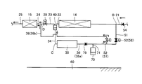
FIG. 1 is a schematic diagram illustrating a configuration of a cooling device 1 according to the first embodiment. As shown in FIG. 1, the cooling device 1 includes a vapor compression refrigeration cycle 10. The vapor compression refrigeration cycle 10 is mounted on a vehicle, for example, to cool the inside of the vehicle. The cooling using the vapor compression refrigeration cycle 10 is selected, for example, when the switch for performing the cooling is turned on or the automatic control mode for automatically adjusting the temperature of the vehicle interior to the set temperature is selected. This is performed when the temperature in the passenger compartment is higher than the set temperature.

蒸気圧縮式冷凍サイクル10は、圧縮機12と、第一熱交換器としての熱交換器14と、熱交換器15と、減圧器の一例としての膨張弁16と、第二熱交換器としての熱交換器18と、を含む。   The vapor compression refrigeration cycle 10 includes a compressor 12, a heat exchanger 14 as a first heat exchanger, a heat exchanger 15, an expansion valve 16 as an example of a decompressor, and a second heat exchanger. And a heat exchanger 18.

圧縮機12は、車両に搭載されたモータまたはエンジンを動力源として作動し、冷媒ガスを断熱的に圧縮して過熱状態冷媒ガスとする。圧縮機12は、蒸気圧縮式冷凍サイクル10の作動時に熱交換器18から流通する冷媒を吸入圧縮して、冷媒通路21に高温高圧の気相冷媒を吐出する。圧縮機12は、冷媒通路21に冷媒を吐出することで、蒸気圧縮式冷凍サイクル10に冷媒を循環させる。   The compressor 12 operates using a motor or engine mounted on the vehicle as a power source, and compresses the refrigerant gas in an adiabatic manner to form an overheated refrigerant gas. The compressor 12 sucks and compresses the refrigerant flowing from the heat exchanger 18 when the vapor compression refrigeration cycle 10 is operated, and discharges a high-temperature and high-pressure gas-phase refrigerant into the refrigerant passage 21. The compressor 12 circulates the refrigerant in the vapor compression refrigeration cycle 10 by discharging the refrigerant into the refrigerant passage 21.

熱交換器14,15は、圧縮機12において圧縮された過熱状態冷媒ガスを、外部媒体へ等圧的に放熱させて冷媒液とする。圧縮機12から吐出された高圧の気相冷媒は、熱交換器14,15において周囲に放熱し冷却されることによって、凝縮(液化)する。熱交換器14,15は、冷媒を流通するチューブと、チューブ内を流通する冷媒と熱交換器14,15の周囲の空気との間で熱交換するためのフィンと、を含む。熱交換器14,15は、車両の走行によって発生する自然の通風またはエンジン冷却用のラジエータファンなどの冷却ファンからの強制通風によって供給された冷却風と冷媒との間で、熱交換を行なう。熱交換器14,15における熱交換によって、冷媒の温度は低下し冷媒は液化する。   The heat exchangers 14 and 15 dissipate the superheated refrigerant gas compressed in the compressor 12 isothermally to an external medium to obtain a refrigerant liquid. The high-pressure gas-phase refrigerant discharged from the compressor 12 is condensed (liquefied) by releasing heat to the surroundings in the heat exchangers 14 and 15 and being cooled. The heat exchangers 14 and 15 include tubes through which the refrigerant flows, and fins for exchanging heat between the refrigerant flowing through the tubes and the air around the heat exchangers 14 and 15. The heat exchangers 14 and 15 exchange heat between the cooling air supplied by natural ventilation generated by traveling of the vehicle or forced ventilation from a cooling fan such as a radiator fan for cooling the engine and the refrigerant. By the heat exchange in the heat exchangers 14 and 15, the temperature of the refrigerant is lowered and the refrigerant is liquefied.

膨張弁16は、冷媒通路25を流通する高圧の液相冷媒を小さな孔から噴射させることにより膨張させて、低温・低圧の霧状冷媒に変化させる。膨張弁16は、熱交換器14,15によって凝縮された冷媒液を減圧して、気液混合状態の湿り蒸気とする。なお、冷媒液を減圧するための減圧器は、絞り膨張する膨張弁16に限られず、毛細管であってもよい。   The expansion valve 16 expands by injecting a high-pressure liquid-phase refrigerant flowing through the refrigerant passage 25 from a small hole, and changes it into a low-temperature / low-pressure mist refrigerant. The expansion valve 16 depressurizes the refrigerant liquid condensed by the heat exchangers 14 and 15 to obtain wet steam in a gas-liquid mixed state. Note that the decompressor for decompressing the refrigerant liquid is not limited to the expansion valve 16 that is squeezed and expanded, and may be a capillary tube.

熱交換器18は、その内部を流通する霧状冷媒が気化することによって、熱交換器18に接触するように導入された周囲の空気の熱を吸収する。熱交換器18は、膨張弁16によって減圧された冷媒を用いて、冷媒の湿り蒸気が蒸発して冷媒ガスとなる際の気化熱を、車両の室内へ流通する空調用空気から吸収して、車両の室内の冷房を行なう。熱が熱交換器18に吸収されることによって温度が低下した空調用空気が車両の室内に再び戻されることによって、車両の室内の冷房が行なわれる。冷媒は、熱交換器18において周囲から吸熱し加熱される。   The heat exchanger 18 absorbs heat of ambient air introduced so as to come into contact with the heat exchanger 18 by vaporizing the mist refrigerant flowing through the heat exchanger 18. The heat exchanger 18 uses the refrigerant depressurized by the expansion valve 16 to absorb the heat of vaporization when the refrigerant's wet vapor evaporates into the refrigerant gas from the air conditioning air flowing into the vehicle interior, Cool the interior of the vehicle. The air-conditioning air whose temperature has been reduced by the heat being absorbed by the heat exchanger 18 is returned again to the vehicle interior, thereby cooling the vehicle interior. The refrigerant absorbs heat from the surroundings in the heat exchanger 18 and is heated.

熱交換器18は、冷媒を流通するチューブと、チューブ内を流通する冷媒と熱交換器18の周囲の空気との間で熱交換するためのフィンと、を含む。チューブ内には、湿り蒸気状態の冷媒が流通する。冷媒は、チューブ内を流通する際に、フィンを経由して車両の室内の空気の熱を蒸発潜熱として吸収することによって蒸発し、さらに顕熱によって過熱蒸気になる。気化した冷媒は、冷媒通路27を経由して圧縮機12へ流通する。圧縮機12は、熱交換器18から流通する冷媒を圧縮する。   The heat exchanger 18 includes a tube through which the refrigerant flows, and fins for exchanging heat between the refrigerant flowing through the tube and the air around the heat exchanger 18. A wet steam refrigerant circulates in the tube. When the refrigerant circulates in the tube, it evaporates by absorbing the heat of the air in the vehicle interior as latent heat of evaporation via the fins, and further becomes superheated steam by sensible heat. The vaporized refrigerant flows to the compressor 12 via the refrigerant passage 27. The compressor 12 compresses the refrigerant flowing from the heat exchanger 18.

蒸気圧縮式冷凍サイクル10はまた、圧縮機12と熱交換器14とを連通する第三通路としての冷媒通路21と、熱交換器14と熱交換器15とを連通する冷媒通路22,23,24と、熱交換器15と膨張弁16とを連通する冷媒通路25と、膨張弁16と熱交換器18とを連通する冷媒通路26と、熱交換器18と圧縮機12とを連通する冷媒通路27と、を含む。   The vapor compression refrigeration cycle 10 also includes a refrigerant passage 21 serving as a third passage for communicating the compressor 12 and the heat exchanger 14, and refrigerant passages 22, 23, communicating the heat exchanger 14 and the heat exchanger 15. 24, a refrigerant passage 25 communicating with the heat exchanger 15 and the expansion valve 16, a refrigerant passage 26 communicating with the expansion valve 16 and the heat exchanger 18, and a refrigerant communicating with the heat exchanger 18 and the compressor 12. And a passage 27.

冷媒通路21は、冷媒を圧縮機12から熱交換器14に流通させるための通路である。冷媒は、冷媒通路21を経由して、圧縮機12と熱交換器14との間を、圧縮機12の出口から熱交換器14の入口へ向かって流れる。冷媒通路22〜25は、冷媒を熱交換器14から膨張弁16に流通させるための通路である。冷媒は、冷媒通路22〜25を経由して、熱交換器14と膨張弁16との間を、熱交換器14の出口から膨張弁16の入口へ向かって流れる。   The refrigerant passage 21 is a passage for circulating the refrigerant from the compressor 12 to the heat exchanger 14. The refrigerant flows between the compressor 12 and the heat exchanger 14 from the outlet of the compressor 12 toward the inlet of the heat exchanger 14 via the refrigerant passage 21. The refrigerant passages 22 to 25 are passages for circulating the refrigerant from the heat exchanger 14 to the expansion valve 16. The refrigerant flows between the heat exchanger 14 and the expansion valve 16 from the outlet of the heat exchanger 14 toward the inlet of the expansion valve 16 via the refrigerant passages 22 to 25.

冷媒通路26は、冷媒を膨張弁16から熱交換器18に流通させるための通路である。冷媒は、冷媒通路26を経由して、膨張弁16と熱交換器18との間を、膨張弁16の出口から熱交換器18の入口へ向かって流れる。冷媒通路27は、冷媒を熱交換器18から圧縮機12に流通させるための通路である。冷媒は、冷媒通路27を経由して、熱交換器18と圧縮機12との間を、熱交換器18の出口から圧縮機12の入口へ向かって流れる。   The refrigerant passage 26 is a passage for circulating the refrigerant from the expansion valve 16 to the heat exchanger 18. The refrigerant flows between the expansion valve 16 and the heat exchanger 18 from the outlet of the expansion valve 16 toward the inlet of the heat exchanger 18 via the refrigerant passage 26. The refrigerant passage 27 is a passage for circulating the refrigerant from the heat exchanger 18 to the compressor 12. The refrigerant flows between the heat exchanger 18 and the compressor 12 from the outlet of the heat exchanger 18 toward the inlet of the compressor 12 via the refrigerant passage 27.

蒸気圧縮式冷凍サイクル10は、圧縮機12、熱交換器14,15、膨張弁16および熱交換器18が、冷媒通路21〜27によって連結されて構成される。なお、蒸気圧縮式冷凍サイクル10の冷媒としては、たとえば二酸化炭素、プロパンやイソブタンなどの炭化水素、アンモニアまたは水などを用いることができる。   The vapor compression refrigeration cycle 10 is configured by connecting a compressor 12, heat exchangers 14 and 15, an expansion valve 16, and a heat exchanger 18 through refrigerant passages 21 to 27. In addition, as a refrigerant of the vapor compression refrigeration cycle 10, for example, carbon dioxide, hydrocarbon such as propane and isobutane, ammonia, water, or the like can be used.

蒸気圧縮式冷凍サイクル10はまた、熱交換器14と膨張弁16との間を流れる冷媒の経路上に配置された、気液分離器40を含む。気液分離器40は、熱交換器14から流出する冷媒を気相冷媒と液相冷媒とに分離する。気液分離器40の内部には、液相冷媒である冷媒液と、気相冷媒である冷媒蒸気と、が蓄蔵されている。気液分離器40には、冷媒通路22,23と、冷媒通路34とが連結されている。   The vapor compression refrigeration cycle 10 also includes a gas-liquid separator 40 disposed on the refrigerant path flowing between the heat exchanger 14 and the expansion valve 16. The gas-liquid separator 40 separates the refrigerant flowing out from the heat exchanger 14 into a gas phase refrigerant and a liquid phase refrigerant. Inside the gas-liquid separator 40, a refrigerant liquid that is a liquid phase refrigerant and a refrigerant vapor that is a gas phase refrigerant are stored. Refrigerant passages 22 and 23 and a refrigerant passage 34 are connected to the gas-liquid separator 40.

熱交換器14の出口側において冷媒は、飽和液と飽和蒸気とが混合した気液二相状態の湿り蒸気の状態にある。熱交換器14から流出した冷媒は、冷媒通路22を通って気液分離器40へ供給される。冷媒通路22から気液分離器40へ流入する気液二相状態の冷媒は、気液分離器40の内部において気相と液相とに分離される。気液分離器40は、熱交換器14によって凝縮された冷媒を液体状の冷媒液とガス状の冷媒蒸気とに分離して、一時的に蓄える。   On the outlet side of the heat exchanger 14, the refrigerant is in a gas-liquid two-phase wet steam state in which a saturated liquid and a saturated steam are mixed. The refrigerant that has flowed out of the heat exchanger 14 is supplied to the gas-liquid separator 40 through the refrigerant passage 22. The gas-liquid two-phase refrigerant flowing into the gas-liquid separator 40 from the refrigerant passage 22 is separated into a gas phase and a liquid phase inside the gas-liquid separator 40. The gas-liquid separator 40 separates the refrigerant condensed by the heat exchanger 14 into a liquid refrigerant liquid and a gaseous refrigerant vapor and temporarily stores them.

分離された冷媒液は、冷媒通路34を経由して、気液分離器40の外部へ流出する。気液分離器40内の液相中に配置された冷媒通路34の端部は、液相冷媒の気液分離器40からの流出口を形成する。分離された冷媒蒸気は、冷媒通路23を経由して、気液分離器40の外部へ流出する。気液分離器40内の気相中に配置された冷媒通路23の端部は、気相冷媒の気液分離器40からの流出口を形成する。気液分離器40から導出された気相の冷媒蒸気は、第三熱交換器としての熱交換器15において周囲に放熱し冷却されることによって、凝縮する。   The separated refrigerant liquid flows out of the gas-liquid separator 40 via the refrigerant passage 34. The end of the refrigerant passage 34 disposed in the liquid phase in the gas-liquid separator 40 forms an outlet for the liquid-phase refrigerant from the gas-liquid separator 40. The separated refrigerant vapor flows out of the gas-liquid separator 40 via the refrigerant passage 23. An end portion of the refrigerant passage 23 arranged in the gas phase in the gas-liquid separator 40 forms an outlet from the gas-liquid separator 40 for the gas-phase refrigerant. The gas-phase refrigerant vapor derived from the gas-liquid separator 40 is condensed by releasing heat to the surroundings and cooling in the heat exchanger 15 as a third heat exchanger.

気液分離器40の内部では、冷媒液が下側、冷媒蒸気が上側に溜まる。気液分離器40から冷媒液を導出する冷媒通路34の端部は、気液分離器40の底部に連結されている。冷媒通路34を経由して、気液分離器40の底側から冷媒液のみが気液分離器40の外部へ送り出される。気液分離器40から冷媒蒸気を導出する冷媒通路23の端部は、気液分離器40の天井部に連結されている。冷媒通路23を経由して、気液分離器40の天井側から冷媒蒸気のみが気液分離器40の外部へ送り出される。これにより、気液分離器40は、気相冷媒と液相冷媒との分離を確実に行なうことができる。   Inside the gas-liquid separator 40, the refrigerant liquid accumulates on the lower side and the refrigerant vapor accumulates on the upper side. The end portion of the refrigerant passage 34 for leading the refrigerant liquid from the gas-liquid separator 40 is connected to the bottom of the gas-liquid separator 40. Only the refrigerant liquid is sent out of the gas-liquid separator 40 from the bottom side of the gas-liquid separator 40 via the refrigerant passage 34. The end portion of the refrigerant passage 23 for leading the refrigerant vapor from the gas-liquid separator 40 is connected to the ceiling portion of the gas-liquid separator 40. Only the refrigerant vapor is sent out of the gas-liquid separator 40 from the ceiling side of the gas-liquid separator 40 via the refrigerant passage 23. As a result, the gas-liquid separator 40 can reliably separate the gas-phase refrigerant and the liquid-phase refrigerant.

熱交換器14の出口から膨張弁16の入口へ向かって流れる冷媒が流通する経路は、熱交換器14の出口側から気液分離器40へ至る冷媒通路22と、気液分離器40から冷媒蒸気を流出させ後述する流量調整弁28を経由する冷媒通路23と、熱交換器15の入口側へ連結される冷媒通路24と、熱交換器15の出口側から冷媒を膨張弁16へ流通させる冷媒通路25と、を含む。第一通路としての冷媒通路23には、気液分離器40で分離された気相冷媒が流れる。   The path through which the refrigerant flowing from the outlet of the heat exchanger 14 toward the inlet of the expansion valve 16 flows is the refrigerant passage 22 extending from the outlet side of the heat exchanger 14 to the gas-liquid separator 40 and from the gas-liquid separator 40 to the refrigerant. The refrigerant flows through the expansion valve 16 from the refrigerant passage 23 through which the steam flows out and passes through a flow rate adjusting valve 28 described later, the refrigerant passage 24 connected to the inlet side of the heat exchanger 15, and the outlet side of the heat exchanger 15. Refrigerant passage 25. The gas phase refrigerant separated by the gas-liquid separator 40 flows through the refrigerant passage 23 as the first passage.

熱交換器14と熱交換器15との間を流通する冷媒の経路はまた、気液分離器40と冷却部30とを連通する冷媒通路34と、冷却部30と冷媒通路24とを連通する冷媒通路36と、を含む。冷媒通路34を経由して、気液分離器40から冷却部30へ冷媒液が流通する。冷却部30を通過した冷媒は、冷媒通路36を経由して、冷媒通路24へ戻る。第二通路としての冷媒通路34,36には、気液分離器40で分離された液相冷媒が流れる。冷却部30は、気液分離器40と膨張弁16との間を熱交換器14から熱交換器15へ向けて流通する冷媒の経路において並列に接続された第一通路と第二通路とのうち、第二通路上に設けられている。   The refrigerant path that flows between the heat exchanger 14 and the heat exchanger 15 also connects the refrigerant passage 34 that connects the gas-liquid separator 40 and the cooling unit 30, and the cooling unit 30 and the refrigerant passage 24. Refrigerant passage 36. The refrigerant liquid flows from the gas-liquid separator 40 to the cooling unit 30 via the refrigerant passage 34. The refrigerant that has passed through the cooling unit 30 returns to the refrigerant passage 24 via the refrigerant passage 36. The liquid phase refrigerant separated by the gas-liquid separator 40 flows through the refrigerant passages 34 and 36 as the second passages. The cooling unit 30 includes a first passage and a second passage that are connected in parallel in a refrigerant path that circulates between the gas-liquid separator 40 and the expansion valve 16 from the heat exchanger 14 toward the heat exchanger 15. Among them, it is provided on the second passage.

図1に示すD点は、冷媒通路23と冷媒通路24と冷媒通路36との連結点を示す。つまりD点は、冷媒通路23の下流側(熱交換器15に近接する側)の端部、冷媒通路24の上流側(熱交換器14に近接する側)の端部、および、冷媒通路36の下流側の端部を示す。冷媒通路23は、気液分離器40から膨張弁16へ向かう冷媒が流通する経路の、気液分離器40からD点へ至る一部を形成する。   A point D shown in FIG. 1 indicates a connection point between the refrigerant passage 23, the refrigerant passage 24, and the refrigerant passage 36. That is, the point D is an end portion on the downstream side (side near the heat exchanger 15) of the refrigerant passage 23, an end portion on the upstream side (side near the heat exchanger 14) of the refrigerant passage 24, and the refrigerant passage 36. The downstream end of is shown. The refrigerant passage 23 forms a part of the path through which the refrigerant from the gas-liquid separator 40 to the expansion valve 16 flows, from the gas-liquid separator 40 to the point D.

冷却装置1は、冷媒通路23と並列に配置された冷媒の経路を備え、冷却部30は、当該冷媒の経路上に設けられている。冷却部30は、車両に搭載される電気機器であるHV(Hybrid Vehicle)機器31と、冷媒が流通する配管である冷却通路32とを含む。HV機器31は、発熱源の一例である。冷却通路32の一方の端部は、冷媒通路34に接続される。冷却通路32の他方の端部は、冷媒通路36に接続される。   The cooling device 1 includes a refrigerant path arranged in parallel with the refrigerant passage 23, and the cooling unit 30 is provided on the refrigerant path. The cooling unit 30 includes an HV (Hybrid Vehicle) device 31 that is an electric device mounted on the vehicle, and a cooling passage 32 that is a pipe through which a refrigerant flows. The HV device 31 is an example of a heat source. One end of the cooling passage 32 is connected to the refrigerant passage 34. The other end of the cooling passage 32 is connected to the refrigerant passage 36.

気液分離器40と図1に示すD点との間の冷媒通路23に並列に接続された冷媒の経路は、冷却部30よりも上流側(気液分離器40に近接する側)の冷媒通路34と、冷却部30に含まれる冷却通路32と、冷却部30よりも下流側(熱交換器15に近接する側)の冷媒通路36と、を含む。冷媒通路34は、気液分離器40から冷却部30に、液相の冷媒を流通させるための通路である。冷媒通路36は、冷却部30からD点に冷媒を流通させるための通路である。D点は、冷媒通路23,24と、冷媒通路36と、の分岐点である。   The refrigerant path connected in parallel to the refrigerant passage 23 between the gas-liquid separator 40 and the point D shown in FIG. 1 is the refrigerant upstream of the cooling unit 30 (the side close to the gas-liquid separator 40). A passage 34, a cooling passage 32 included in the cooling unit 30, and a refrigerant passage 36 on the downstream side (side closer to the heat exchanger 15) than the cooling unit 30 are included. The refrigerant passage 34 is a passage through which a liquid-phase refrigerant flows from the gas-liquid separator 40 to the cooling unit 30. The refrigerant passage 36 is a passage for circulating the refrigerant from the cooling unit 30 to the point D. Point D is a branch point between the refrigerant passages 23 and 24 and the refrigerant passage 36.

気液分離器40から流出した冷媒液は、冷媒通路34を経由して、冷却部30へ向かって流通する。冷却部30へ流通し、冷却通路32を経由して流れる冷媒は、発熱源としてのHV機器31から熱を奪って、HV機器31を冷却させる。冷却部30は、気液分離器40において分離され冷媒通路34を経由して冷却通路32へ流れる液相の冷媒を用いて、HV機器31を冷却する。冷却部30において、冷却通路32内を流通する冷媒と、HV機器31と、が熱交換することにより、HV機器31は冷却され、冷媒は加熱される。冷媒はさらに冷媒通路36を経由して冷却部30からD点へ向かって流通し、冷媒通路24を経由して熱交換器15へ至る。   The refrigerant liquid that has flowed out of the gas-liquid separator 40 flows through the refrigerant passage 34 toward the cooling unit 30. The refrigerant flowing to the cooling unit 30 and flowing through the cooling passage 32 takes heat from the HV device 31 as a heat generation source and cools the HV device 31. The cooling unit 30 cools the HV equipment 31 using a liquid-phase refrigerant that is separated in the gas-liquid separator 40 and flows to the cooling passage 32 via the refrigerant passage 34. In the cooling unit 30, the refrigerant flowing through the cooling passage 32 and the HV equipment 31 exchange heat, whereby the HV equipment 31 is cooled and the refrigerant is heated. The refrigerant further flows from the cooling unit 30 toward the point D via the refrigerant passage 36 and reaches the heat exchanger 15 via the refrigerant passage 24.

冷却部30は、冷却通路32においてHV機器31と冷媒との間で熱交換が可能な構造を有するように設けられる。本実施の形態においては、冷却部30は、たとえば、HV機器31の筐体に冷却通路32の外周面が直接接触するように形成された冷却通路32を有する。冷却通路32は、HV機器31の筐体と隣接する部分を有する。当該部分において、冷却通路32を流通する冷媒と、HV機器31との間で、熱交換が可能となる。   The cooling unit 30 is provided so as to have a structure capable of exchanging heat between the HV device 31 and the refrigerant in the cooling passage 32. In the present embodiment, the cooling unit 30 includes, for example, a cooling passage 32 formed so that the outer peripheral surface of the cooling passage 32 directly contacts the housing of the HV device 31. The cooling passage 32 has a portion adjacent to the housing of the HV device 31. In this part, heat exchange can be performed between the refrigerant flowing through the cooling passage 32 and the HV equipment 31.

HV機器31は、蒸気圧縮式冷凍サイクル10の熱交換器14から熱交換器15に至る冷媒の経路の一部を形成する冷却通路32の外周面に直接接続されて、冷却される。冷却通路32の外部にHV機器31が配置されるので、冷却通路32の内部を流通する冷媒の流れにHV機器31が干渉することはない。そのため、蒸気圧縮式冷凍サイクル10の圧力損失は増大しないので、圧縮機12の動力を増大させることなく、HV機器31を冷却することができる。   The HV device 31 is directly connected to the outer peripheral surface of the cooling passage 32 that forms a part of the refrigerant path from the heat exchanger 14 to the heat exchanger 15 of the vapor compression refrigeration cycle 10 to be cooled. Since the HV device 31 is disposed outside the cooling passage 32, the HV device 31 does not interfere with the flow of the refrigerant flowing through the cooling passage 32. Therefore, since the pressure loss of the vapor compression refrigeration cycle 10 does not increase, the HV equipment 31 can be cooled without increasing the power of the compressor 12.

代替的には、冷却部30は、HV機器31と冷却通路32との間に介在して配置された任意の公知のヒートパイプを備えてもよい。この場合HV機器31は、冷却通路32の外周面にヒートパイプを介して接続され、HV機器31から冷却通路32へヒートパイプを経由して熱伝達することにより、冷却される。HV機器31をヒートパイプの加熱部とし冷却通路32をヒートパイプの冷却部とすることで、冷却通路32とHV機器31との間の熱伝達効率が高められるので、HV機器31の冷却効率を向上できる。たとえばウィック式のヒートパイプを使用することができる。   Alternatively, the cooling unit 30 may include any known heat pipe disposed between the HV device 31 and the cooling passage 32. In this case, the HV device 31 is connected to the outer peripheral surface of the cooling passage 32 via a heat pipe, and is cooled by transferring heat from the HV device 31 to the cooling passage 32 via the heat pipe. Since the heat transfer efficiency between the cooling passage 32 and the HV equipment 31 can be increased by using the HV equipment 31 as the heat pipe heating section and the cooling passage 32 as the heat pipe cooling section, the cooling efficiency of the HV equipment 31 can be increased. It can be improved. For example, a wick-type heat pipe can be used.

ヒートパイプによってHV機器31から冷却通路32へ確実に熱伝達することができるので、HV機器31と冷却通路32との間に距離があってもよく、HV機器31に冷却通路32を接触させるために冷却通路32を複雑に配置する必要がない。その結果、HV機器31の配置の自由度を向上することができる。   Since heat can be reliably transferred from the HV device 31 to the cooling passage 32 by the heat pipe, there may be a distance between the HV device 31 and the cooling passage 32, and the cooling passage 32 is brought into contact with the HV device 31. Therefore, it is not necessary to arrange the cooling passage 32 in a complicated manner. As a result, the degree of freedom of arrangement of the HV device 31 can be improved.

HV機器31は、電力の授受によって発熱する電気機器を含む。電気機器は、たとえば、直流電力を交流電力に変換するためのインバータ、回転電機であるモータジェネレータ、蓄電装置であるバッテリ、バッテリの電圧を昇圧させるためのコンバータ、バッテリの電圧を降圧するためのDC/DCコンバータなどの、少なくともいずれか一つを含む。バッテリは、リチウムイオン電池あるいはニッケル水素電池等の二次電池である。バッテリに代えてキャパシタが用いられてもよい。   The HV device 31 includes an electrical device that generates heat when power is transferred. The electrical equipment includes, for example, an inverter for converting DC power into AC power, a motor generator that is a rotating electrical machine, a battery that is a power storage device, a converter that boosts the voltage of the battery, and a DC that steps down the voltage of the battery. Including at least one of DC / DC converters and the like. The battery is a secondary battery such as a lithium ion battery or a nickel metal hydride battery. A capacitor may be used instead of the battery.

熱交換器18は、空気が流通するダクト90の内部に配置されている。熱交換器18は、冷媒とダクト90内を流通する空調用空気との間で熱交換して、空調用空気の温度を調節する。ダクト90は、ダクト90に空調用空気が流入する入口であるダクト入口91と、ダクト90から空調用空気が流出する出口であるダクト出口92と、を有する。ダクト90の内部の、ダクト入口91の近傍には、ファン93が配置されている。   The heat exchanger 18 is disposed inside a duct 90 through which air flows. The heat exchanger 18 exchanges heat between the refrigerant and the air-conditioning air flowing through the duct 90 to adjust the temperature of the air-conditioning air. The duct 90 has a duct inlet 91 that is an inlet through which air-conditioning air flows into the duct 90, and a duct outlet 92 that is an outlet through which air-conditioning air flows out from the duct 90. A fan 93 is disposed in the vicinity of the duct inlet 91 inside the duct 90.

ファン93が駆動することにより、ダクト90内に空気が流通する。ファン93が稼働すると、ダクト入口91を経由してダクト90の内部へ空調用空気が流入する。ダクト90へ流入する空気は、外気であってもよく、車両の室内の空気であってもよい。図1中の矢印95は、熱交換器18を経由して流通し、蒸気圧縮式冷凍サイクル10の冷媒と熱交換する空調用空気の流れを示す。冷房運転時には、熱交換器18において空調用空気が冷却され、冷媒は空調用空気からの熱伝達を受けて加熱される。矢印96は、熱交換器18で温度調節され、ダクト出口92を経由してダクト90から流出する、空調用空気の流れを示す。   When the fan 93 is driven, air flows in the duct 90. When the fan 93 is in operation, air for air conditioning flows into the duct 90 via the duct inlet 91. The air flowing into the duct 90 may be outside air or air in the vehicle interior. An arrow 95 in FIG. 1 indicates the flow of air-conditioning air that flows through the heat exchanger 18 and exchanges heat with the refrigerant of the vapor compression refrigeration cycle 10. During the cooling operation, the air-conditioning air is cooled in the heat exchanger 18, and the refrigerant is heated by receiving heat transfer from the air-conditioning air. An arrow 96 indicates the flow of air-conditioning air that is temperature-adjusted by the heat exchanger 18 and flows out of the duct 90 via the duct outlet 92.

冷媒は、圧縮機12と熱交換器14,15と膨張弁16と熱交換器18とが冷媒通路21〜27によって順次接続された冷媒循環流路を通って、蒸気圧縮式冷凍サイクル10内を循環する。蒸気圧縮式冷凍サイクル10内を、図1に示すA点、B点、C点、D点、E点およびF点を順に通過するように冷媒が流れ、圧縮機12と熱交換器14,15と膨張弁16と熱交換器18とに冷媒が循環する。   The refrigerant passes through the refrigerant circulation passage in which the compressor 12, the heat exchangers 14 and 15, the expansion valve 16, and the heat exchanger 18 are sequentially connected by the refrigerant passages 21 to 27, and passes through the vapor compression refrigeration cycle 10. Circulate. The refrigerant flows through the vapor compression refrigeration cycle 10 through the points A, B, C, D, E, and F shown in FIG. 1 in order, and the compressor 12 and the heat exchangers 14 and 15 are passed through. The refrigerant circulates through the expansion valve 16 and the heat exchanger 18.

図2は、蒸気圧縮式冷凍サイクル10の冷媒の状態を示すモリエル線図である。図2中の横軸は、冷媒の比エンタルピー(単位:kJ/kg)を示し、縦軸は、冷媒の絶対圧力(単位:MPa)を示す。図中の曲線は、冷媒の飽和蒸気線および飽和液線である。図2中には、熱交換器14の出口の冷媒通路22から気液分離器40を経由して冷媒通路34へ流入し、HV機器31を冷却し、冷媒通路36からD点を経由して熱交換器15の入口の冷媒通路24へ戻る、蒸気圧縮式冷凍サイクル10中の各点(すなわちA,B,C,D,EおよびF点)における冷媒の熱力学状態が示される。   FIG. 2 is a Mollier diagram showing the state of the refrigerant in the vapor compression refrigeration cycle 10. The horizontal axis in FIG. 2 represents the specific enthalpy (unit: kJ / kg) of the refrigerant, and the vertical axis represents the absolute pressure (unit: MPa) of the refrigerant. The curves in the figure are the saturated vapor line and saturated liquid line of the refrigerant. In FIG. 2, the refrigerant flows from the refrigerant passage 22 at the outlet of the heat exchanger 14 to the refrigerant passage 34 via the gas-liquid separator 40, cools the HV equipment 31, and passes through the point D from the refrigerant passage 36. The thermodynamic state of the refrigerant at each point in the vapor compression refrigeration cycle 10 (ie, points A, B, C, D, E, and F) returning to the refrigerant passage 24 at the inlet of the heat exchanger 15 is shown.

図2に示すように、圧縮機12に吸入された過熱蒸気状態の冷媒(A点)は、圧縮機12において等比エントロピー線に沿って断熱圧縮される。圧縮するに従って冷媒の圧力と温度とが上昇し、高温高圧の過熱度の大きい過熱蒸気になって(B点)、冷媒は熱交換器14へと流れる。圧縮機12から吐出された気相冷媒は、熱交換器14において周囲に放熱し冷却されることによって、凝縮(液化)する。熱交換器14における外気との熱交換によって、冷媒の温度は低下し冷媒は液化する。熱交換器14へ入った高圧の冷媒蒸気は、熱交換器14において等圧のまま過熱蒸気から乾き飽和蒸気になり、凝縮潜熱を放出し徐々に液化して気液混合状態の湿り蒸気になる。気液二相状態である冷媒のうち、凝縮した冷媒は飽和液の状態である(C点)。   As shown in FIG. 2, the superheated vapor refrigerant (point A) sucked into the compressor 12 is adiabatically compressed along the isentropic line in the compressor 12. As the compressor is compressed, the pressure and temperature of the refrigerant rise and become high-temperature and high-pressure superheated steam (point B), and the refrigerant flows to the heat exchanger 14. The gas-phase refrigerant discharged from the compressor 12 is condensed (liquefied) by releasing heat to the surroundings in the heat exchanger 14 and being cooled. By the heat exchange with the outside air in the heat exchanger 14, the temperature of the refrigerant is lowered and the refrigerant is liquefied. The high-pressure refrigerant vapor that has entered the heat exchanger 14 changes from superheated steam to dry saturated vapor while maintaining the same pressure in the heat exchanger 14, releases latent heat of condensation, gradually liquefies, and becomes wet vapor in a gas-liquid mixed state. . Of the refrigerant in the gas-liquid two-phase state, the condensed refrigerant is in a saturated liquid state (point C).

冷媒は気液分離器40において気相冷媒と液相冷媒とに分離される。気液分離された冷媒のうち、液相の冷媒液が、気液分離器40から冷媒通路34を経由して冷却部30の冷却通路32へ流れ、HV機器31を冷却する。冷却部30において、熱交換器14を通過して凝縮された飽和液状態の液冷媒に熱を放出することで、HV機器31が冷却される。HV機器31との熱交換により、冷媒が加熱され、冷媒の乾き度が増大する。冷媒は、HV機器31から潜熱を受け取って一部気化することにより、飽和液と飽和蒸気とが混合した湿り蒸気となる(D点)。   The refrigerant is separated into a gas phase refrigerant and a liquid phase refrigerant in the gas-liquid separator 40. Among the gas-liquid separated refrigerant, liquid-phase refrigerant liquid flows from the gas-liquid separator 40 through the refrigerant passage 34 to the cooling passage 32 of the cooling unit 30 to cool the HV equipment 31. In the cooling unit 30, the HV equipment 31 is cooled by releasing heat to the liquid refrigerant in the saturated liquid state that is condensed after passing through the heat exchanger 14. By the heat exchange with the HV equipment 31, the refrigerant is heated and the dryness of the refrigerant increases. The refrigerant receives the latent heat from the HV device 31 and partially evaporates to become wet steam in which the saturated liquid and saturated steam are mixed (point D).

その後冷媒は、熱交換器15に流入する。冷媒の湿り蒸気は、熱交換器15において外気と熱交換して冷却されることにより再度凝縮され、冷媒の全部が凝縮すると飽和液になり、さらに顕熱を放出して過冷却された過冷却液になる(E点)。その後冷媒は、冷媒通路25を経由して膨張弁16に流入する。膨張弁16において、過冷却液状態の冷媒は絞り膨張され、比エンタルピーは変化せず温度と圧力とが低下して、低温低圧の気液混合状態の湿り蒸気となる(F点)。   Thereafter, the refrigerant flows into the heat exchanger 15. The wet steam of the refrigerant is condensed again by exchanging heat with the outside air in the heat exchanger 15 and is condensed again. When all of the refrigerant is condensed, it becomes a saturated liquid and further subcooled by releasing sensible heat. Become liquid (point E). Thereafter, the refrigerant flows into the expansion valve 16 via the refrigerant passage 25. In the expansion valve 16, the refrigerant in the supercooled liquid state is squeezed and expanded, the specific enthalpy does not change, the temperature and pressure are reduced, and the low temperature and low pressure gas-liquid mixed vapor is obtained (point F).

膨張弁16から出た湿り蒸気状態の冷媒は、冷媒通路26を経由して熱交換器18へ流入する。熱交換器18のチューブ内には、湿り蒸気状態の冷媒が流入する。冷媒は、熱交換器18のチューブ内を流通する際に、フィンを経由して車両の室内の空気の熱を蒸発潜熱として吸収することによって、等圧のまま蒸発する。全ての冷媒が乾き飽和蒸気になると、さらに顕熱によって冷媒蒸気は温度上昇して、過熱蒸気となる(A点)。その後冷媒は、冷媒通路27を経由して圧縮機12に吸入される。圧縮機12は、熱交換器18から流通する冷媒を圧縮する。   The wet steam refrigerant that has flowed out of the expansion valve 16 flows into the heat exchanger 18 via the refrigerant passage 26. A wet steam refrigerant flows into the tube of the heat exchanger 18. When the refrigerant circulates in the tube of the heat exchanger 18, it absorbs the heat of the air in the vehicle interior via the fins as latent heat of vaporization, and evaporates at a constant pressure. When all the refrigerants are dry and become saturated vapor, the temperature of the refrigerant vapor further rises due to sensible heat and becomes superheated vapor (point A). Thereafter, the refrigerant is sucked into the compressor 12 via the refrigerant passage 27. The compressor 12 compresses the refrigerant flowing from the heat exchanger 18.

冷媒はこのようなサイクルに従って、圧縮、凝縮、絞り膨張、蒸発の状態変化を連続的に繰り返す。なお、上述した蒸気圧縮式冷凍サイクルの説明では、理論冷凍サイクルについて説明しているが、実際の蒸気圧縮式冷凍サイクル10では、圧縮機12における損失、冷媒の圧力損失および熱損失を考慮する必要があるのは勿論である。   In accordance with such a cycle, the refrigerant continuously repeats the compression, condensation, throttle expansion, and evaporation state changes. In the above description of the vapor compression refrigeration cycle, the theoretical refrigeration cycle is described. However, in the actual vapor compression refrigeration cycle 10, it is necessary to consider the loss in the compressor 12, the pressure loss of the refrigerant, and the heat loss. Of course there is.

蒸気圧縮式冷凍サイクル10の運転中に、冷媒は、蒸発器として作用する熱交換器18において蒸発する際に気化熱を車両の室内の空気から吸収して、車室内の冷房を行なう。加えて、熱交換器14から流出し気液分離器40で気液分離された高圧の液冷媒が冷却部30へ流通し、HV機器31と熱交換することでHV機器31を冷却する。冷却装置1は、車両に搭載された発熱源であるHV機器31を、車両の室内の空調用の蒸気圧縮式冷凍サイクル10を利用して、冷却する。なお、HV機器31を冷却するために必要とされる温度は、少なくともHV機器31の温度範囲として目標となる温度範囲の上限値よりも低い温度であることが望ましい。   During the operation of the vapor compression refrigeration cycle 10, the refrigerant absorbs heat of vaporization from the air in the vehicle interior when evaporating in the heat exchanger 18 acting as an evaporator, thereby cooling the vehicle interior. In addition, the high-pressure liquid refrigerant that has flowed out of the heat exchanger 14 and separated into gas and liquid by the gas-liquid separator 40 flows to the cooling unit 30, and heat-exchanges with the HV device 31 to cool the HV device 31. The cooling device 1 cools the HV equipment 31 that is a heat source mounted on the vehicle by using a vapor compression refrigeration cycle 10 for air conditioning in the vehicle interior. Note that the temperature required for cooling the HV device 31 is desirably at least lower than the upper limit value of the target temperature range as the temperature range of the HV device 31.

熱交換器18において被冷却部を冷却するために設けられた蒸気圧縮式冷凍サイクル10を利用して、HV機器31の冷却が行なわれるので、HV機器31の冷却のために、専用の水循環ポンプまたは冷却ファンなどの機器を設ける必要はない。そのため、HV機器31の冷却装置1のために必要な構成を低減でき、装置構成を単純にできるので、冷却装置1の製造コストを低減することができる。加えて、HV機器31の冷却のためにポンプや冷却ファンなどの動力源を運転する必要がなく、動力源を運転するための消費動力を必要としない。したがって、HV機器31の冷却のための消費動力を低減することができる。   Since the HV equipment 31 is cooled using the vapor compression refrigeration cycle 10 provided to cool the part to be cooled in the heat exchanger 18, a dedicated water circulation pump is used to cool the HV equipment 31. Or it is not necessary to provide equipment, such as a cooling fan. Therefore, the configuration necessary for the cooling device 1 of the HV equipment 31 can be reduced and the device configuration can be simplified, so that the manufacturing cost of the cooling device 1 can be reduced. In addition, there is no need to operate a power source such as a pump or a cooling fan for cooling the HV equipment 31, and no power consumption is required to operate the power source. Therefore, power consumption for cooling the HV equipment 31 can be reduced.

熱交換器14では、冷媒を湿り蒸気の状態にまで冷却すればよく、気液混合状態の冷媒は気液分離器40により分離され、飽和液状態の冷媒液のみが冷却部30へ供給される。HV機器31から蒸発潜熱を受け取り一部気化した湿り蒸気の状態の冷媒は、熱交換器15で再度冷却される。湿り蒸気状態の冷媒を凝縮させ完全に飽和液にするまで、冷媒は一定の温度で状態変化する。熱交換器15はさらに、車両の室内の冷房のために必要な程度の過冷却度にまで、液相冷媒を過冷却する。冷媒の過冷却度を過度に大きくする必要がないので、熱交換器14,15の容量を低減することができる。したがって、車室用の冷房能力を確保でき、かつ、熱交換器14,15のサイズを低減することができるので小型化され車載用に有利な、冷却装置1を得ることができる。   In the heat exchanger 14, it is only necessary to cool the refrigerant to a wet steam state, the refrigerant in the gas-liquid mixed state is separated by the gas-liquid separator 40, and only the refrigerant liquid in the saturated liquid state is supplied to the cooling unit 30. . The refrigerant in the state of wet steam that has received the latent heat of evaporation from the HV device 31 and is partially vaporized is cooled again by the heat exchanger 15. The refrigerant changes its state at a constant temperature until the wet vapor state refrigerant is condensed and completely saturated. The heat exchanger 15 further subcools the liquid refrigerant to a degree of supercooling necessary for cooling the vehicle interior. Since it is not necessary to excessively increase the degree of supercooling of the refrigerant, the capacity of the heat exchangers 14 and 15 can be reduced. Therefore, the cooling capacity for the passenger compartment can be ensured, and the size of the heat exchangers 14 and 15 can be reduced, so that the cooling device 1 that is downsized and advantageous for in-vehicle use can be obtained.

熱交換器14の出口から膨張弁16の入口へ向かう冷媒の経路の一部を形成する冷媒通路23は、熱交換器14と熱交換器15との間に設けられている。気液分離器40から膨張弁16へ向かう冷媒が流通する経路として、冷却部30を通過しない経路である冷媒通路23と、冷却部30を経由してHV機器31を冷却する冷媒の経路である冷媒通路34,36および冷却通路32と、が並列に設けられる。冷媒通路34,36を含むHV機器31の冷却系は、冷媒通路23と並列に接続されている。そのため、熱交換器14から流出した冷媒の一部のみが、冷却部30へ流れる。HV機器31の冷却のために必要な量の冷媒を冷却部30へ流通させ、HV機器31は適切に冷却される。したがって、HV機器31が過冷却されることを防止できる。   A refrigerant passage 23 that forms a part of the refrigerant path from the outlet of the heat exchanger 14 to the inlet of the expansion valve 16 is provided between the heat exchanger 14 and the heat exchanger 15. The refrigerant flow from the gas-liquid separator 40 toward the expansion valve 16 is a refrigerant path 23 that is a path that does not pass through the cooling unit 30 and a refrigerant path that cools the HV equipment 31 via the cooling unit 30. The refrigerant passages 34 and 36 and the cooling passage 32 are provided in parallel. The cooling system of the HV device 31 including the refrigerant passages 34 and 36 is connected in parallel with the refrigerant passage 23. Therefore, only a part of the refrigerant that has flowed out of the heat exchanger 14 flows to the cooling unit 30. An amount of refrigerant necessary for cooling the HV device 31 is circulated to the cooling unit 30, and the HV device 31 is appropriately cooled. Therefore, it is possible to prevent the HV device 31 from being overcooled.

熱交換器14から直接熱交換器15へ流れる冷媒の経路と、熱交換器14から冷却部30を経由して熱交換器15へ流れる冷媒の経路と、を並列に設け、一部の冷媒のみを冷媒通路34,36へ流通させることで、HV機器31の冷却系に冷媒が流れる際の圧力損失を低減することができる。全ての冷媒が冷却部30に流れないので、冷却部30を経由する冷媒の流通に係る圧力損失を低減することができ、それに伴い、冷媒を循環させるための圧縮機12の運転に必要な消費電力を低減することができる。   A refrigerant path flowing directly from the heat exchanger 14 to the heat exchanger 15 and a refrigerant path flowing from the heat exchanger 14 to the heat exchanger 15 via the cooling unit 30 are provided in parallel, and only a part of the refrigerants are provided. Is allowed to flow through the refrigerant passages 34 and 36, so that pressure loss when the refrigerant flows into the cooling system of the HV equipment 31 can be reduced. Since all the refrigerant does not flow to the cooling unit 30, it is possible to reduce pressure loss related to the circulation of the refrigerant passing through the cooling unit 30, and accordingly, consumption necessary for the operation of the compressor 12 for circulating the refrigerant. Electric power can be reduced.

膨張弁16を通過した後の低温低圧の冷媒をHV機器31の冷却に使用すると、熱交換器18における車室内の空気の冷却能力が減少して、車室用の冷房能力が低下する。これに対し、本実施の形態の冷却装置1では、蒸気圧縮式冷凍サイクル10において、圧縮機12から吐出された高圧の冷媒は、第一の凝縮器としての熱交換器14と、第二の凝縮器としての熱交換器15と、の両方によって凝縮される。圧縮機12と膨張弁16との間に二段の熱交換器14,15を配置し、HV機器31を冷却する冷却部30は、熱交換器14と熱交換器15との間に設けられている。熱交換器15は、冷却部30から膨張弁16に向けて流通する冷媒の経路上に設けられている。   If the low-temperature and low-pressure refrigerant after passing through the expansion valve 16 is used for cooling the HV equipment 31, the cooling capacity of the air in the passenger compartment in the heat exchanger 18 decreases, and the cooling capacity for the passenger compartment decreases. On the other hand, in the cooling device 1 of the present embodiment, the high-pressure refrigerant discharged from the compressor 12 in the vapor compression refrigeration cycle 10 is converted into the heat exchanger 14 as the first condenser, and the second It is condensed by both the heat exchanger 15 as a condenser. The two-stage heat exchangers 14 and 15 are disposed between the compressor 12 and the expansion valve 16, and the cooling unit 30 that cools the HV equipment 31 is provided between the heat exchanger 14 and the heat exchanger 15. ing. The heat exchanger 15 is provided on a refrigerant path that circulates from the cooling unit 30 toward the expansion valve 16.

HV機器31から蒸発潜熱を受けて加熱された冷媒を熱交換器15において十分に冷却することにより、膨張弁16の出口において、冷媒は、車両の室内の冷房のために本来必要とされる温度および圧力を有する。そのため、熱交換器18において冷媒が蒸発するときに外部から受け取る熱量を十分に大きくすることができる。このように、冷媒を十分に冷却できる熱交換器15の放熱能力を定めることにより、車室内の空気を冷却する冷房の能力に影響を与えることなく、HV機器31を冷却することができる。したがって、HV機器31の冷却能力と、車室用の冷房能力との両方を、確実に確保することができる。   The refrigerant heated by receiving the latent heat of vaporization from the HV device 31 is sufficiently cooled in the heat exchanger 15, so that the refrigerant at the outlet of the expansion valve 16 has a temperature originally required for cooling the vehicle interior. And having pressure. Therefore, the amount of heat received from the outside when the refrigerant evaporates in the heat exchanger 18 can be sufficiently increased. Thus, by defining the heat dissipation capability of the heat exchanger 15 that can sufficiently cool the refrigerant, the HV device 31 can be cooled without affecting the cooling capability of cooling the air in the passenger compartment. Therefore, both the cooling capacity of the HV device 31 and the cooling capacity for the passenger compartment can be ensured reliably.

熱交換器14から冷却部30へ流れる冷媒は、HV機器31を冷却するときに、HV機器31から熱を受け取り加熱される。冷却部30において冷媒が飽和蒸気温度以上に加熱され冷媒の全量が気化すると、冷媒とHV機器31との熱交換量が減少してHV機器31を効率よく冷却できなくなり、また冷媒が配管内を流れる際の圧力損失が増大する。そのため、HV機器31を冷却した後に冷媒の全量が気化しない程度に、熱交換器14において十分に冷媒を冷却するのが望ましい。   The refrigerant flowing from the heat exchanger 14 to the cooling unit 30 receives heat from the HV device 31 and is heated when the HV device 31 is cooled. When the refrigerant is heated to the saturated vapor temperature or higher in the cooling unit 30 and the entire amount of the refrigerant is vaporized, the amount of heat exchange between the refrigerant and the HV device 31 is reduced, and the HV device 31 cannot be efficiently cooled. Pressure loss during flow increases. Therefore, it is desirable to cool the refrigerant sufficiently in the heat exchanger 14 so that the entire amount of the refrigerant does not vaporize after the HV device 31 is cooled.

具体的には、熱交換器14の出口における冷媒の状態を飽和液に近づけ、典型的には熱交換器14の出口において冷媒が飽和液線上にある状態にする。このように冷媒を十分に冷却できる能力を熱交換器14が有する結果、熱交換器14の冷媒から熱を放出させる放熱能力は、熱交換器15の放熱能力よりも高くなる。放熱能力が相対的に大きい熱交換器14において冷媒を十分に冷却することにより、HV機器31から熱を受け取った冷媒を湿り蒸気の状態に留めることができ、冷媒とHV機器31との熱交換量の減少を回避できるので、HV機器31を十分に効率よく冷却することができる。HV機器31を冷却した後の湿り蒸気の状態の冷媒は、熱交換器15において効率よく再度冷却され、飽和温度を下回る過冷却液の状態にまで冷却される。したがって、車室用の冷房能力とHV機器31の冷却能力との両方を確保した、冷却装置1を提供することができる。   Specifically, the state of the refrigerant at the outlet of the heat exchanger 14 is brought close to the saturated liquid, and typically, the refrigerant is on the saturated liquid line at the outlet of the heat exchanger 14. As a result of the heat exchanger 14 having the ability to sufficiently cool the refrigerant in this way, the heat dissipating ability for releasing heat from the refrigerant of the heat exchanger 14 is higher than the heat dissipating ability of the heat exchanger 15. By sufficiently cooling the refrigerant in the heat exchanger 14 having a relatively large heat dissipation capability, the refrigerant that has received heat from the HV device 31 can be kept in a wet steam state, and heat exchange between the refrigerant and the HV device 31 can be achieved. Since the decrease in the amount can be avoided, the HV device 31 can be cooled sufficiently efficiently. The refrigerant in the state of wet steam after cooling the HV device 31 is efficiently cooled again in the heat exchanger 15 and cooled to the state of the supercooled liquid below the saturation temperature. Therefore, it is possible to provide the cooling device 1 that secures both the cooling capacity for the passenger compartment and the cooling capacity of the HV device 31.

熱交換器14の出口において気液二相状態にある冷媒は、気液分離器40内において、気相と液相とに分離される。気液分離器40で分離された気相冷媒は、冷媒通路23,24を経由して流通し直接熱交換器15に供給される。気液分離器40で分離された液相冷媒は、冷媒通路34を経由して流通し、冷却部30に供給されてHV機器31を冷却する。この液相冷媒は、過不足の全くない真に飽和液状態の冷媒である。気液分離器40から液相の冷媒のみを取り出し冷却部30へ流すことにより、熱交換器14の能力を最大限に活用してHV機器31を冷却することができるので、HV機器31の冷却能力を向上させた冷却装置1を提供することができる。   The refrigerant in a gas-liquid two-phase state at the outlet of the heat exchanger 14 is separated into a gas phase and a liquid phase in the gas-liquid separator 40. The gas-phase refrigerant separated by the gas-liquid separator 40 flows through the refrigerant passages 23 and 24 and is directly supplied to the heat exchanger 15. The liquid phase refrigerant separated by the gas-liquid separator 40 flows through the refrigerant passage 34 and is supplied to the cooling unit 30 to cool the HV equipment 31. This liquid-phase refrigerant is a truly saturated liquid refrigerant with no excess or deficiency. By taking out only the liquid phase refrigerant from the gas-liquid separator 40 and flowing it to the cooling unit 30, the HV equipment 31 can be cooled by utilizing the capacity of the heat exchanger 14 to the maximum, so that the HV equipment 31 is cooled. The cooling device 1 with improved performance can be provided.

気液分離器40の出口で飽和液の状態にある冷媒をHV機器31を冷却する冷却通路32に導入することにより、冷媒通路34,36および冷却通路32を含むHV機器31の冷却系を流れる冷媒のうち、気相状態の冷媒を最小限に抑えることができる。そのため、HV機器31の冷却系を流れる冷媒蒸気の流速が早くなり圧力損失が増大することを抑制でき、冷媒を流通させるための圧縮機12の消費電力を低減できるので、蒸気圧縮式冷凍サイクル10の性能の悪化を回避することができる。   The refrigerant in the saturated liquid state at the outlet of the gas-liquid separator 40 is introduced into the cooling passage 32 that cools the HV equipment 31, thereby flowing through the cooling system of the HV equipment 31 including the refrigerant passages 34 and 36 and the cooling passage 32. Among the refrigerants, the gas-phase refrigerant can be minimized. Therefore, it is possible to suppress an increase in pressure loss due to an increase in the flow rate of the refrigerant vapor flowing through the cooling system of the HV equipment 31, and it is possible to reduce power consumption of the compressor 12 for circulating the refrigerant. The deterioration of the performance can be avoided.

気液分離器40の内部には、飽和液状態の冷媒液が貯留されている。気液分離器40は、その内部に液状の冷媒である冷媒液を一時的に貯留する機能を有する。気液分離器40内に所定量の冷媒液が溜められることにより、負荷変動時にも気液分離器40から冷却部30へ流れる冷媒の流量を維持できる。気液分離器40が液だめ機能を有し、負荷変動に対するバッファとなり負荷変動を吸収できるので、HV機器31の冷却性能を安定させることができる。   A refrigerant liquid in a saturated liquid state is stored inside the gas-liquid separator 40. The gas-liquid separator 40 has a function of temporarily storing a refrigerant liquid that is a liquid refrigerant therein. By storing a predetermined amount of the refrigerant liquid in the gas-liquid separator 40, the flow rate of the refrigerant flowing from the gas-liquid separator 40 to the cooling unit 30 can be maintained even when the load changes. Since the gas-liquid separator 40 has a liquid reservoir function and becomes a buffer against load fluctuations and can absorb the load fluctuations, the cooling performance of the HV equipment 31 can be stabilized.

図1に戻って、冷却装置1は、流量調整弁28を備える。流量調整弁28は、熱交換器14から膨張弁16へ向かう冷媒の経路において、並列に接続された経路のうちの一方を形成する、冷媒通路23に配置されている。流量調整弁28は、その弁開度を変動させ、冷媒通路23を流れる冷媒の圧力損失を増減させることにより、冷媒通路23を流れる冷媒の流量と、冷却通路32を含むHV機器31の冷却系を流れる冷媒の流量と、を任意に調節する。   Returning to FIG. 1, the cooling device 1 includes a flow rate adjusting valve 28. The flow regulating valve 28 is disposed in the refrigerant passage 23 that forms one of the paths connected in parallel in the refrigerant path from the heat exchanger 14 to the expansion valve 16. The flow rate adjusting valve 28 varies the valve opening degree and increases / decreases the pressure loss of the refrigerant flowing through the refrigerant passage 23, thereby cooling the flow rate of the refrigerant flowing through the refrigerant passage 23 and the cooling system of the HV equipment 31 including the cooling passage 32. The flow rate of the refrigerant flowing through is arbitrarily adjusted.

たとえば、流量調整弁28を全閉にして弁開度を0%にすると、熱交換器14を出た冷媒の全量が気液分離器40から冷媒通路34へ流入する。流量調整弁28の弁開度を大きくすれば、熱交換器14から冷媒通路22へ流れる冷媒のうち、冷媒通路23を経由して熱交換器15へ直接流れる流量が大きくなり、冷媒通路34を経由して冷却通路32へ流れHV機器31を冷却する冷媒の流量が小さくなる。流量調整弁28の弁開度を小さくすれば、熱交換器14から冷媒通路22へ流れる冷媒のうち、冷媒通路23を経由して熱交換器15へ直接流れる流量が小さくなり、冷却通路32を経由して流れHV機器31を冷却する冷媒の流量が大きくなる。   For example, when the flow rate adjustment valve 28 is fully closed and the valve opening degree is 0%, the entire amount of the refrigerant that has exited the heat exchanger 14 flows from the gas-liquid separator 40 into the refrigerant passage 34. If the valve opening degree of the flow rate adjustment valve 28 is increased, the flow rate of the refrigerant flowing from the heat exchanger 14 to the refrigerant passage 22 directly flowing to the heat exchanger 15 via the refrigerant passage 23 increases, and the refrigerant passage 34 is The flow rate of the refrigerant that flows to the cooling passage 32 via the route and cools the HV device 31 decreases. If the valve opening degree of the flow rate adjusting valve 28 is reduced, the flow rate of the refrigerant flowing from the heat exchanger 14 to the refrigerant passage 22 directly flowing to the heat exchanger 15 via the refrigerant passage 23 is reduced, and the cooling passage 32 is The flow rate of the refrigerant that flows through and cools the HV device 31 increases.

流量調整弁28の弁開度を大きくするとHV機器31を冷却する冷媒の流量が小さくなり、HV機器31の冷却能力が低下する。流量調整弁28の弁開度を小さくするとHV機器31を冷却する冷媒の流量が大きくなり、HV機器31の冷却能力が向上する。流量調整弁28を使用して、HV機器31に流れる冷媒の量を最適に調節できるので、HV機器31の過冷却を確実に防止することができ、加えて、HV機器31の冷却系の冷媒の流通に係る圧力損失および冷媒を循環させるための圧縮機12の消費電力を、確実に低減することができる。   When the valve opening degree of the flow rate adjusting valve 28 is increased, the flow rate of the refrigerant that cools the HV device 31 is decreased, and the cooling capacity of the HV device 31 is decreased. When the valve opening degree of the flow rate adjusting valve 28 is decreased, the flow rate of the refrigerant that cools the HV device 31 is increased, and the cooling capacity of the HV device 31 is improved. Since the amount of the refrigerant flowing through the HV device 31 can be optimally adjusted using the flow rate adjusting valve 28, the overcooling of the HV device 31 can be surely prevented, and in addition, the refrigerant of the cooling system of the HV device 31 It is possible to reliably reduce the pressure loss and the power consumption of the compressor 12 for circulating the refrigerant.

冷却装置1はまた、連通路51を備える。連通路51は、圧縮機12と熱交換器14との間を冷媒が流通する冷媒通路21と、冷却部30に冷媒を流通させる冷媒通路34,36のうち冷却部30に対し下流側の冷媒通路36と、を連通する。冷媒通路36および連通路51には、連通路51と冷媒通路21,36との連通状態を切り換える切換弁52が設けられている。切換弁52は、その開閉を切り換えることにより、連通路51を経由する冷媒の流通を可能または不可能にする。冷媒通路36は、連通路51との分岐よりも上流側の冷媒通路36aと、連通路51との分岐よりも下流側の冷媒通路36bと、に二分割される。   The cooling device 1 also includes a communication passage 51. The communication passage 51 is a refrigerant downstream of the cooling unit 30 among the refrigerant passage 21 through which the refrigerant flows between the compressor 12 and the heat exchanger 14 and the refrigerant passages 34, 36 through which the refrigerant flows through the cooling unit 30. The passage 36 communicates with the passage 36. The refrigerant passage 36 and the communication passage 51 are provided with a switching valve 52 that switches the communication state between the communication passage 51 and the refrigerant passages 21 and 36. The switching valve 52 enables or disables the circulation of the refrigerant via the communication path 51 by switching its opening and closing. The refrigerant passage 36 is divided into a refrigerant passage 36 a upstream from the branch with the communication passage 51 and a refrigerant passage 36 b downstream from the branch with the communication passage 51.

切換弁52を使用して冷媒の経路を切り換えることにより、HV機器31を冷却した後の冷媒を、冷媒通路36b,24を経由させて熱交換器15へ、または、連通路51および冷媒通路21を経由して熱交換器14へ、のいずれかの経路を任意に選択して、流通させることができる。   By switching the refrigerant path using the switching valve 52, the refrigerant after cooling the HV equipment 31 passes through the refrigerant passages 36 b and 24 to the heat exchanger 15, or the communication passage 51 and the refrigerant passage 21. Any of the paths to the heat exchanger 14 via can be arbitrarily selected and distributed.

より具体的には、切換弁52として二つの弁57,58が設けられている。蒸気圧縮式冷凍サイクル10の冷房運転中には、弁57を全開(弁開度100%)とし弁58を全閉(弁開度0%)とし、流量調整弁28の弁開度を冷却部30に十分な冷媒が流れるように調整する。これにより、HV機器31を冷却した後の冷媒通路36aを流通する冷媒を、冷媒通路36bを経由させて、確実に熱交換器15へ流通させることができる。一方、蒸気圧縮式冷凍サイクル10の停止中には、弁58を全開とし弁57を全閉とし、さらに流量調整弁28を全閉とする。これにより、HV機器31を冷却した後の冷媒通路36aを流通する冷媒を、連通路51を経由させて熱交換器14へ流通させ、冷却部30と熱交換器14との間に冷媒を循環させる環状の経路を形成することができる。   More specifically, two valves 57 and 58 are provided as the switching valve 52. During the cooling operation of the vapor compression refrigeration cycle 10, the valve 57 is fully opened (valve opening degree 100%), the valve 58 is fully closed (valve opening degree 0%), and the valve opening degree of the flow control valve 28 is set to the cooling unit. 30 is adjusted so that sufficient refrigerant flows. Thereby, the refrigerant | coolant which distribute | circulates the refrigerant path 36a after cooling the HV apparatus 31 can be reliably distribute | circulated to the heat exchanger 15 via the refrigerant path 36b. On the other hand, while the vapor compression refrigeration cycle 10 is stopped, the valve 58 is fully opened, the valve 57 is fully closed, and the flow rate adjustment valve 28 is fully closed. Thereby, the refrigerant flowing through the refrigerant passage 36 a after cooling the HV device 31 is circulated to the heat exchanger 14 via the communication path 51, and the refrigerant is circulated between the cooling unit 30 and the heat exchanger 14. An annular path can be formed.

冷却装置1はさらに、冷媒通路36に接続された蓄ガス器70を備える。蓄ガス器70は、冷却部30に対し下流側の冷媒の経路に設けられている。蓄ガス器70は、冷却部30と、冷媒通路36と連通路51との分岐点と、の間に配置されている。つまり、蓄ガス器70は、冷媒通路36aに接続されている。   The cooling device 1 further includes a gas storage unit 70 connected to the refrigerant passage 36. The gas storage unit 70 is provided in the refrigerant path downstream of the cooling unit 30. The gas storage device 70 is disposed between the cooling unit 30 and the branch point between the refrigerant passage 36 and the communication passage 51. That is, the gas storage device 70 is connected to the refrigerant passage 36a.

蓄ガス器70は、冷却部30において冷媒液がHV機器31から伝熱されて気化した後の飽和蒸気状態の気相冷媒を、その内部に貯留する。冷媒通路36を流れる高圧の冷媒が蓄ガス器70の内部へ流入し、蓄ガス器70は流入した冷媒蒸気を蓄積する。冷媒通路36を流れる冷媒の圧力が低下すると、蓄ガス器70の中に入っていた冷媒蒸気を蓄ガス器70から冷媒通路36へ放出して、冷媒通路36を流通する冷媒蒸気の流量の低下を抑制する。   The gas accumulator 70 stores therein the vapor phase refrigerant in a saturated vapor state after the refrigerant liquid is transferred from the HV device 31 and vaporized in the cooling unit 30. The high-pressure refrigerant flowing through the refrigerant passage 36 flows into the gas accumulator 70, and the gas accumulator 70 accumulates the flowing refrigerant vapor. When the pressure of the refrigerant flowing through the refrigerant passage 36 decreases, the refrigerant vapor contained in the gas accumulator 70 is discharged from the gas accumulator 70 to the refrigerant passage 36, and the flow rate of the refrigerant vapor flowing through the refrigerant passage 36 decreases. Suppress.

冷却部30と蓄ガス器70との間に、逆止弁79が配置されている。逆止弁79は、蓄ガス器70から流出する冷媒蒸気が冷却部30へ逆流するのを防止する。逆止弁79は、冷媒蒸気が蓄ガス器70から排出され冷媒通路36へ流れるとき、冷媒蒸気が冷却部30側へ流れることなく、冷却部30に対し下流側の冷媒通路36と連通路51との分岐点へ向かって確実に冷媒蒸気が流れるように、設けられている。逆止弁79は、冷却部30から蓄ガス器70へ向かう気相冷媒の流れを許容するとともに、蓄ガス器70から流出する気相冷媒の冷却部30へ向かう流れを禁止する。   A check valve 79 is disposed between the cooling unit 30 and the gas storage unit 70. The check valve 79 prevents the refrigerant vapor flowing out of the gas storage unit 70 from flowing back to the cooling unit 30. When the refrigerant vapor is discharged from the gas accumulator 70 and flows into the refrigerant passage 36, the check valve 79 does not flow into the cooling portion 30 side, and the refrigerant passage 36 and the communication passage 51 on the downstream side with respect to the cooling portion 30. It is provided so that the refrigerant vapor flows reliably toward the branch point. The check valve 79 allows the flow of the gas-phase refrigerant from the cooling unit 30 toward the gas storage unit 70 and prohibits the flow of the gas-phase refrigerant flowing out from the gas storage unit 70 toward the cooling unit 30.

図3は、蒸気圧縮式冷凍サイクル10の運転中の、HV機器31を冷却する冷媒の流れを示す模式図である。図3には、蒸気圧縮式冷凍サイクル10を運転させる場合、すなわち圧縮機12を運転させて蒸気圧縮式冷凍サイクル10の全体に冷媒を流通させる場合の、冷媒の流れが示される。   FIG. 3 is a schematic diagram showing a refrigerant flow for cooling the HV equipment 31 during operation of the vapor compression refrigeration cycle 10. FIG. 3 shows the flow of the refrigerant when the vapor compression refrigeration cycle 10 is operated, that is, when the compressor 12 is operated and the refrigerant is circulated throughout the vapor compression refrigeration cycle 10.

図3に示すように、圧縮機12を駆動させ蒸気圧縮式冷凍サイクル10が運転している「エアコン運転モード」のときには、流量調整弁28は、冷却部30に十分な冷媒が流れるように、弁開度を調整される。切換弁52は、冷媒を冷却部30から熱交換器15を経由して膨張弁16へ流通させるように操作される。すなわち、弁57を全開にし弁58を全閉にすることで、冷媒が冷却装置1の全体を流れるように冷媒の経路が選択される。そのため、蒸気圧縮式冷凍サイクル10の冷却能力を確保できるとともに、HV機器31を効率よく冷却することができる。   As shown in FIG. 3, when in the “air conditioner operation mode” in which the compressor 12 is driven and the vapor compression refrigeration cycle 10 is operating, the flow rate adjustment valve 28 is configured so that sufficient refrigerant flows through the cooling unit 30. The valve opening is adjusted. The switching valve 52 is operated so that the refrigerant flows from the cooling unit 30 to the expansion valve 16 via the heat exchanger 15. That is, the refrigerant path is selected so that the refrigerant flows through the entire cooling device 1 by fully opening the valve 57 and fully closing the valve 58. Therefore, the cooling capacity of the vapor compression refrigeration cycle 10 can be ensured and the HV equipment 31 can be efficiently cooled.

図4は、図3に示す蓄ガス器70の詳細を示す拡大図である。蓄ガス器70と冷媒通路36とは、接続部71を介して接続されている。冷媒通路36から接続部71を経由して蓄ガス器70の内部へ気相冷媒が流入可能であり、また蓄ガス器70から接続部71を経由して冷媒通路36へ気相冷媒が流出可能である。   FIG. 4 is an enlarged view showing details of the gas storage device 70 shown in FIG. 3. The gas accumulator 70 and the refrigerant passage 36 are connected via a connection portion 71. Gas phase refrigerant can flow into the gas storage unit 70 from the refrigerant passage 36 via the connection portion 71, and gas phase refrigerant can flow out of the gas storage unit 70 to the refrigerant passage 36 via the connection portion 71. It is.

蓄ガス器70は中空に形成され、蓄ガス器70の内部には可動仕切部72が配置されている。可動仕切部72は、冷媒通路36から可動仕切部72までの距離を変更するように、冷媒通路36へ近づきまたは冷媒通路36から離れる方向に、自在に移動可能である。可動仕切部72によって、蓄ガス器70の内部空間は、冷媒蒸気を受け容れる蒸気収容部73と、気体が封入されたガス封入部74と、に分けられている。蒸気収容部73は、接続部71を介して、冷媒通路36と連通する。ガス封入部74は、その内部に注入された窒素などの圧縮性気体の漏洩を防ぐように、密封されている。   The gas storage unit 70 is formed in a hollow shape, and a movable partition 72 is disposed inside the gas storage unit 70. The movable partition portion 72 is freely movable in a direction toward or away from the refrigerant passage 36 so as to change the distance from the refrigerant passage 36 to the movable partition portion 72. The movable partition 72 divides the internal space of the gas accumulator 70 into a steam accommodating part 73 that receives the refrigerant vapor and a gas enclosing part 74 that encloses gas. The vapor storage portion 73 communicates with the refrigerant passage 36 via the connection portion 71. The gas sealing part 74 is sealed so as to prevent leakage of a compressible gas such as nitrogen injected therein.

蒸気収容部73を密封するために、蒸気収容部73に面する側の可動仕切部72の表面の周縁部には、封止材78が配置されている。封止材78は、たとえばゴム材料製のOリング形状に形成されており、蒸気収容部73とガス封入部74とが連通するのを防止する。封止材78は、可動仕切部72と蓄ガス器70の筐体との隙間を通って気相冷媒が蒸気収容部73からガス封入部74へ漏洩することを防止し、かつ、可動仕切部72と蓄ガス器70の筐体との隙間を通ってガス封入部74内の気体が蒸気収容部73へ混入することを防止している。   In order to seal the steam accommodating portion 73, a sealing material 78 is disposed on the peripheral portion of the surface of the movable partition portion 72 on the side facing the steam accommodating portion 73. The sealing material 78 is formed, for example, in an O-ring shape made of a rubber material, and prevents the vapor storage portion 73 and the gas sealing portion 74 from communicating with each other. The sealing material 78 prevents the gas-phase refrigerant from leaking from the vapor storage part 73 to the gas sealing part 74 through the gap between the movable partition part 72 and the housing of the gas storage unit 70, and the movable partition part The gas in the gas sealing part 74 is prevented from being mixed into the vapor accommodating part 73 through the gap between 72 and the housing of the gas storage unit 70.

可動仕切部72が冷媒通路36から離れる方向に移動することにより、蒸気収容部73の容積が相対的に増大し、ガス封入部74の容積が相対的に減少する。このとき、蒸気収容部73内に溜められる冷媒蒸気の量が増大しており、ガス封入部74内の気体が圧縮されてガス封入部74の内圧が増加している。   By moving the movable partition 72 in a direction away from the refrigerant passage 36, the volume of the vapor accommodating portion 73 is relatively increased, and the volume of the gas sealing portion 74 is relatively decreased. At this time, the amount of the refrigerant vapor stored in the vapor storage portion 73 is increased, the gas in the gas enclosure 74 is compressed, and the internal pressure of the gas enclosure 74 is increased.

可動仕切部72が冷媒通路36へ近づく方向に移動することにより、蒸気収容部73の容積が相対的に減少し、ガス封入部74の容積が相対的に増大する。このとき、蒸気収容部73内に溜められる冷媒蒸気の量が減少しており、ガス封入部74内の気体が膨張してガス封入部74の内圧が減少している。   When the movable partition 72 moves in a direction approaching the refrigerant passage 36, the volume of the vapor storage unit 73 is relatively decreased, and the volume of the gas sealing unit 74 is relatively increased. At this time, the amount of the refrigerant vapor stored in the vapor accommodating portion 73 is reduced, the gas in the gas enclosure 74 is expanded, and the internal pressure of the gas enclosure 74 is reduced.

図3に示す「エアコン運転モード」のときには、圧縮機12が運転しているので、冷媒通路36には、高圧の飽和蒸気状態の冷媒が流れる。そのため冷媒は、冷媒通路36を図4に示す矢印方向に流れる。このとき、一部の冷媒は冷却部30から冷媒通路36を経由して熱交換器15へ流れ、一部の冷媒は冷媒通路36から蓄ガス器70の蒸気収容部73へ流入して蒸気収容部73に貯留される。   In the “air conditioner operation mode” shown in FIG. 3, since the compressor 12 is in operation, high-pressure saturated vapor refrigerant flows through the refrigerant passage 36. Therefore, the refrigerant flows through the refrigerant passage 36 in the arrow direction shown in FIG. At this time, a part of the refrigerant flows from the cooling unit 30 via the refrigerant passage 36 to the heat exchanger 15, and a part of the refrigerant flows from the refrigerant passage 36 into the vapor storage unit 73 of the gas accumulator 70 to store the vapor. Stored in the unit 73.

圧縮機12で冷媒の圧力を上昇させ、冷媒通路36と蓄ガス器70の内部との間に圧力差を形成することで、冷媒液を蓄ガス器70に充填することができる。そのため、冷媒蒸気を蓄ガス器70へ流入させるための追加の動力は不要である。高圧の冷媒蒸気が蒸気収容部73へ流入することにより、冷媒蒸気によって可動仕切部72に圧力が加えられ、可動仕切部72は図4の点線矢印に示すように冷媒通路36から離れる側へ移動する。これにより、より多くの冷媒蒸気を蓄ガス器70に溜め込むことができる。   By increasing the pressure of the refrigerant by the compressor 12 and forming a pressure difference between the refrigerant passage 36 and the inside of the gas accumulator 70, the refrigerant liquid can be filled in the gas accumulator 70. Therefore, no additional power is required to flow the refrigerant vapor into the gas accumulator 70. When the high-pressure refrigerant vapor flows into the vapor accommodating portion 73, pressure is applied to the movable partition portion 72 by the refrigerant vapor, and the movable partition portion 72 moves to the side away from the refrigerant passage 36 as shown by the dotted arrow in FIG. To do. As a result, more refrigerant vapor can be stored in the gas accumulator 70.

図5は、蒸気圧縮式冷凍サイクル10の停止中の、HV機器31を冷却する冷媒の流れを示す模式図である。図5には、蒸気圧縮式冷凍サイクル10を停止させる場合、すなわち、圧縮機12を停止させ、冷却部30と熱交換器14とを結ぶ環状の経路を経由させて冷媒を循環させる場合の、冷媒の流れが示される。   FIG. 5 is a schematic diagram showing a refrigerant flow for cooling the HV equipment 31 while the vapor compression refrigeration cycle 10 is stopped. In FIG. 5, when the vapor compression refrigeration cycle 10 is stopped, that is, when the compressor 12 is stopped and the refrigerant is circulated through an annular path connecting the cooling unit 30 and the heat exchanger 14, The refrigerant flow is shown.

図5に示すように、圧縮機12を停止させ蒸気圧縮式冷凍サイクル10が停止している「ヒートパイプ運転モード」のときには、冷媒を冷却部30から熱交換器14へ循環させるように切換弁52を操作する。すなわち、弁57を全閉にし弁58を全開にし、さらに流量調整弁28を全閉にすることで、冷媒は冷媒通路36bへは流れず連通路51を経由して流通する。このように切換弁52の開閉を設定することにより、熱交換器14から、冷媒通路22と冷媒通路34とを順に経由して冷却部30へ至り、さらに冷媒通路36a、連通路51、冷媒通路21を順に経由して熱交換器14へ戻る、閉じられた環状の経路が形成される。   As shown in FIG. 5, in the “heat pipe operation mode” in which the compressor 12 is stopped and the vapor compression refrigeration cycle 10 is stopped, the switching valve is configured to circulate the refrigerant from the cooling unit 30 to the heat exchanger 14. 52 is operated. That is, the valve 57 is fully closed, the valve 58 is fully opened, and the flow rate adjustment valve 28 is fully closed, whereby the refrigerant flows through the communication path 51 without flowing to the refrigerant path 36b. By setting the opening / closing of the switching valve 52 in this way, the heat exchanger 14 reaches the cooling unit 30 via the refrigerant passage 22 and the refrigerant passage 34 in order, and further, the refrigerant passage 36a, the communication passage 51, and the refrigerant passage. A closed annular path is formed, which in turn passes through 21 and returns to the heat exchanger 14.

この環状の経路を経由して、圧縮機12を動作することなく、熱交換器14と冷却部30との間に冷媒を循環させることができる。冷媒は、HV機器31を冷却するとき、HV機器31から蒸発潜熱を受けて蒸発する。HV機器31との熱交換により気化された冷媒蒸気は、冷媒通路36a、連通路51および冷媒通路21を順に経由して、熱交換器14へ流れる。熱交換器14において、車両の走行風またはエンジン冷却用のラジエータファンからの通風により、冷媒蒸気は冷却されて凝縮する。熱交換器14で液化した冷媒液は、冷媒通路22,34を経由して、冷却部30へ戻る。   Via this annular path, the refrigerant can be circulated between the heat exchanger 14 and the cooling unit 30 without operating the compressor 12. When the HV device 31 is cooled, the refrigerant receives evaporation latent heat from the HV device 31 and evaporates. The refrigerant vapor evaporated by heat exchange with the HV device 31 flows to the heat exchanger 14 through the refrigerant passage 36a, the communication passage 51, and the refrigerant passage 21 in order. In the heat exchanger 14, the refrigerant vapor is cooled and condensed by the running air of the vehicle or the ventilation from the radiator fan for cooling the engine. The refrigerant liquid liquefied by the heat exchanger 14 returns to the cooling unit 30 via the refrigerant passages 22 and 34.

このように、冷却部30と熱交換器14とを経由する環状の経路によって、HV機器31を加熱部とし熱交換器14を冷却部とする、ヒートパイプが形成される。したがって、蒸気圧縮式冷凍サイクル10が停止しているとき、すなわち車両用の冷房が停止しているときにも、圧縮機12を起動する必要なく、HV機器31を確実に冷却することができる。HV機器31の冷却のために圧縮機12を常時運転する必要がないことにより、圧縮機12の消費動力を低減して車両の燃費を向上することができ、加えて、圧縮機12を長寿命化できるので圧縮機12の信頼性を向上することができる。   Thus, a heat pipe is formed by the annular path passing through the cooling unit 30 and the heat exchanger 14, with the HV equipment 31 as a heating unit and the heat exchanger 14 as a cooling unit. Therefore, even when the vapor compression refrigeration cycle 10 is stopped, that is, when cooling for the vehicle is stopped, the HV equipment 31 can be reliably cooled without having to start the compressor 12. Since it is not necessary to always operate the compressor 12 for cooling the HV equipment 31, the power consumption of the compressor 12 can be reduced and the fuel consumption of the vehicle can be improved. In addition, the compressor 12 has a long service life. Therefore, the reliability of the compressor 12 can be improved.

図3および図5には、地面60が図示されている。地面60に対して垂直な鉛直方向において、冷却部30は、熱交換器14よりも下方に配置されている。熱交換器14と冷却部30との間に冷媒を循環させる環状の経路において、冷却部30が下方に配置され、熱交換器14が上方に配置される。熱交換器14は、冷却部30よりも高い位置に配置される。   3 and 5 illustrate the ground 60. FIG. The cooling unit 30 is disposed below the heat exchanger 14 in the vertical direction perpendicular to the ground 60. In an annular path for circulating the refrigerant between the heat exchanger 14 and the cooling unit 30, the cooling unit 30 is disposed below and the heat exchanger 14 is disposed above. The heat exchanger 14 is disposed at a position higher than the cooling unit 30.

この場合、冷却部30で加熱され気化した冷媒蒸気は、環状の経路内を上昇して熱交換器14へ到達し、熱交換器14において冷却され、凝縮されて液冷媒となり、重力の作用により環状の経路内を下降して冷却部30へ戻る。つまり、冷却部30と、熱交換器14と、これらを連結する冷媒の経路とによって、サーモサイフォン式のヒートパイプが形成される。ヒートパイプを形成することでHV機器31から熱交換器14への熱伝達効率を向上することができるので、蒸気圧縮式冷凍サイクル10が停止しているときにも、動力を加えることなく、HV機器31をより効率よく冷却することができる。   In this case, the refrigerant vapor heated and vaporized in the cooling unit 30 rises in the annular path and reaches the heat exchanger 14, is cooled in the heat exchanger 14, is condensed and becomes a liquid refrigerant, and acts by gravity. It descends in the annular path and returns to the cooling unit 30. That is, a thermosiphon heat pipe is formed by the cooling unit 30, the heat exchanger 14, and the refrigerant path connecting them. Since the heat transfer efficiency from the HV device 31 to the heat exchanger 14 can be improved by forming the heat pipe, even when the vapor compression refrigeration cycle 10 is stopped, the HV is not applied. The device 31 can be cooled more efficiently.

連通路51と冷媒通路21,36との連通状態を切り換える切換弁52としては、上述した一対の弁57,58を使用してもよく、または、冷媒通路36と連通路51との分岐に配置された三方弁を使用してもよい。いずれの場合でも、蒸気圧縮式冷凍サイクル10の運転時および停止時の両方において、HV機器31を効率よく冷却することができる。弁57,58は、冷媒通路の開閉ができる単純な構造であればよいので安価であり、二つの弁57,58を使用することにより、より低コストな冷却装置1を提供することができる。一方、二つの弁57,58を配置するよりも三方弁の配置に要する空間はより小さくてよいと考えられ、三方弁を使用することにより、より小型化され車両搭載性に優れた冷却装置1を提供することができる。   As the switching valve 52 for switching the communication state between the communication passage 51 and the refrigerant passages 21, 36, the above-described pair of valves 57, 58 may be used, or arranged at a branch between the refrigerant passage 36 and the communication passage 51. It is also possible to use a three-way valve. In any case, the HV equipment 31 can be efficiently cooled both when the vapor compression refrigeration cycle 10 is operated and when it is stopped. The valves 57 and 58 are inexpensive because they only need to have a simple structure capable of opening and closing the refrigerant passage. By using the two valves 57 and 58, the cooling device 1 can be provided at a lower cost. On the other hand, it is considered that the space required for the arrangement of the three-way valve may be smaller than the arrangement of the two valves 57 and 58. By using the three-way valve, the cooling device 1 is further downsized and has excellent vehicle mountability. Can be provided.

冷却装置1はさらに、逆止弁54を備える。逆止弁54は、圧縮機12と熱交換器14との間の冷媒通路21の、冷媒通路21と連通路51との接続箇所よりも圧縮機12に近接する側に、配置されている。逆止弁54は、圧縮機12から熱交換器14へ向かう冷媒の流れを許容するとともに、その逆向きの冷媒の流れを禁止する。このようにすれば、図5に示すヒートパイプ運転モードのとき、熱交換器14と冷却部30との間に冷媒を循環させる閉ループ状の冷媒の経路を、確実に形成することができる。   The cooling device 1 further includes a check valve 54. The check valve 54 is disposed on the refrigerant passage 21 between the compressor 12 and the heat exchanger 14 on the side closer to the compressor 12 than the connection point between the refrigerant passage 21 and the communication passage 51. The check valve 54 allows the refrigerant flow from the compressor 12 to the heat exchanger 14 and prohibits the reverse refrigerant flow. In this way, in the heat pipe operation mode shown in FIG. 5, a closed loop refrigerant path for circulating the refrigerant between the heat exchanger 14 and the cooling unit 30 can be reliably formed.

逆止弁54がない場合、冷媒が連通路51から圧縮機12側の冷媒通路21へ流れる虞がある。逆止弁54を備えることによって、連通路51から圧縮機12側へ向かう冷媒の流れを確実に禁止できるので、環状の冷媒経路で形成するヒートパイプを使用した、蒸気圧縮式冷凍サイクル10の停止時のHV機器31の冷却能力の低下を防止できる。したがって、車両の車室用の冷房が停止しているときにも、HV機器31を効率よく冷却することができる。   If the check valve 54 is not provided, the refrigerant may flow from the communication passage 51 to the refrigerant passage 21 on the compressor 12 side. By providing the check valve 54, the flow of the refrigerant from the communication path 51 toward the compressor 12 can be surely prohibited. Therefore, the stop of the vapor compression refrigeration cycle 10 using the heat pipe formed by the annular refrigerant path is used. It is possible to prevent a decrease in the cooling capacity of the HV device 31 at the time. Therefore, the HV device 31 can be efficiently cooled even when the cooling for the passenger compartment of the vehicle is stopped.

また、蒸気圧縮式冷凍サイクル10の停止中に、閉ループ状の冷媒の経路内の冷媒の量が不足する場合には、圧縮機12を短時間のみ運転することで、逆止弁54を経由して閉ループ経路に冷媒を供給できる。これにより、閉ループ内の冷媒量を増加させ、ヒートパイプの熱交換処理量を増大させることができる。したがって、ヒートパイプの冷媒量を確保することができるので、冷媒量の不足のためにHV機器31の冷却が不十分となることを回避することができる。   In addition, when the amount of refrigerant in the closed loop refrigerant path is insufficient while the vapor compression refrigeration cycle 10 is stopped, the compressor 12 is operated only for a short time, thereby passing through the check valve 54. Thus, the refrigerant can be supplied to the closed loop path. Thereby, the refrigerant | coolant amount in a closed loop can be increased and the heat exchange processing amount of a heat pipe can be increased. Therefore, since the amount of refrigerant in the heat pipe can be secured, it is possible to avoid insufficient cooling of the HV device 31 due to the insufficient amount of refrigerant.

図6は、図5に示す蓄ガス器70の詳細を示す拡大図である。「ヒートパイプ運転モード」のときには、圧縮機12が停止している。サーモサイフォン式のヒートパイプを形成する閉ループ状の冷媒の経路内で冷媒を移動させる駆動力は、液状の冷媒に作用する重力、および、ガス状の冷媒に作用する浮力のみとなる。「エアコン運転モード」のときと比較して、「ヒートパイプ運転モード」のときには、冷媒に作用する駆動力が相対的に小さくなる。そのため、「ヒートパイプ運転モード」のとき、冷媒の駆動力が不足し、閉ループ状の冷媒の経路内に冷媒を流通させるために必要な駆動力が確保できないことが懸念される。   FIG. 6 is an enlarged view showing details of the gas storage device 70 shown in FIG. 5. When in the “heat pipe operation mode”, the compressor 12 is stopped. The driving force for moving the refrigerant in the closed loop refrigerant path forming the thermosiphon heat pipe is only gravity acting on the liquid refrigerant and buoyancy acting on the gaseous refrigerant. Compared to the “air conditioner operation mode”, the driving force acting on the refrigerant is relatively small in the “heat pipe operation mode”. Therefore, in the “heat pipe operation mode”, there is a concern that the driving force of the refrigerant is insufficient, and that the driving force necessary for circulating the refrigerant in the closed loop refrigerant path cannot be ensured.

特に、「エアコン運転モード」から「ヒートパイプ運転モード」への切替のために圧縮機12を停止させた直後、冷媒が循環を開始しHV機器31の冷却が再開されるまでにタイムラグが発生し、HV機器31の冷却性能が低下する問題がある。これは、閉ループ内の気化されたガス冷媒の流量が少ないと、ガス冷媒に作用する浮力が小さく、そのため、ガス状の冷媒がある程度の量に達するまで、初動に必要な冷媒の駆動力が確保できず、閉ループ内での冷媒の循環が行なわれないことが原因と考えられる。   In particular, there is a time lag immediately after the compressor 12 is stopped for switching from the “air conditioner operation mode” to the “heat pipe operation mode”, until the refrigerant starts to circulate and the cooling of the HV equipment 31 is resumed. There is a problem that the cooling performance of the HV equipment 31 is lowered. This is because when the flow rate of the vaporized gas refrigerant in the closed loop is small, the buoyancy acting on the gas refrigerant is small, so that the driving force of the refrigerant necessary for the initial movement is ensured until the gaseous refrigerant reaches a certain amount. This is probably because the refrigerant is not circulated in the closed loop.

本実施の形態の冷却装置1では、冷却部30の下流側に蓄ガス器70が配置され、圧縮機12の運転中に蓄ガス器70内に冷媒蒸気が溜められる。「ヒートパイプ運転モード」への切替が行なわれるとき、圧縮機12が停止するので、冷媒通路36を流れる冷媒の圧力が相対的に低下する。蓄ガス器70に貯留された気相冷媒の圧力よりも冷媒通路36を流れる冷媒の圧力の方が小さくなると、冷媒は、図6に示す矢印方向に、蓄ガス器70の蒸気収容部73から流出して冷媒通路36へ流れる。蓄ガス器70から冷媒液が流出し、蒸気収容部73内に貯留された冷媒蒸気の量が減少することにより、冷媒蒸気から可動仕切部72に作用する圧力が低下する。これにより、可動仕切部72は図6の点線矢印に示すように冷媒通路36へ近づく側へ移動する。   In the cooling device 1 of the present embodiment, the gas storage unit 70 is disposed on the downstream side of the cooling unit 30, and refrigerant vapor is stored in the gas storage unit 70 during the operation of the compressor 12. When the switching to the “heat pipe operation mode” is performed, the compressor 12 is stopped, so that the pressure of the refrigerant flowing through the refrigerant passage 36 is relatively lowered. When the pressure of the refrigerant flowing through the refrigerant passage 36 becomes smaller than the pressure of the gas-phase refrigerant stored in the gas accumulator 70, the refrigerant flows from the vapor storage portion 73 of the gas accumulator 70 in the arrow direction shown in FIG. It flows out to the refrigerant passage 36. As the refrigerant liquid flows out from the gas storage unit 70 and the amount of the refrigerant vapor stored in the vapor storage portion 73 decreases, the pressure acting on the movable partition portion 72 from the refrigerant vapor decreases. Thereby, the movable partition part 72 moves to the side approaching the refrigerant path 36, as shown by the dotted line arrow of FIG.

圧縮機12を停止させ、発熱源であるHV機器31を冷却するための冷媒の駆動力が低下するときに、冷媒蒸気を蓄ガス器70から放出して冷媒通路36へ流通させることで、閉ループ状の経路を流通する気相冷媒の流量の低下を抑制する。このようにして冷媒蒸気を補充することにより、閉ループ状の冷媒の経路内を流れる気相冷媒の流量を確保でき、冷媒の駆動力としての気相冷媒に作用する浮力を十分に確保することができる。そのため、「ヒートパイプ運転モード」の始動時のHV機器31の冷却能力の低下を抑制し、HV機器31の冷却性能を確保して、HV機器31を安定して冷却することができる。したがって、HV機器31の温度上昇を効果的に抑制することができる。   When the compressor 12 is stopped and the driving force of the refrigerant for cooling the HV device 31 that is a heat generation source is reduced, the refrigerant vapor is discharged from the gas accumulator 70 and circulated to the refrigerant passage 36, thereby closing the loop. The decrease in the flow rate of the gas-phase refrigerant flowing through the path is suppressed. By replenishing the refrigerant vapor in this way, the flow rate of the gas-phase refrigerant flowing in the closed-loop refrigerant path can be ensured, and sufficient buoyancy acting on the gas-phase refrigerant as the driving force of the refrigerant can be ensured. it can. Therefore, a decrease in the cooling capacity of the HV device 31 at the start of the “heat pipe operation mode” can be suppressed, the cooling performance of the HV device 31 can be secured, and the HV device 31 can be stably cooled. Therefore, the temperature rise of the HV device 31 can be effectively suppressed.

このとき、逆止弁79が設けられることにより、蓄ガス器70から冷媒通路36へ圧送された冷媒が冷却部30側へ逆流することを防止できる。したがって、蓄ガス器70から気相冷媒を、閉ループ状の経路内の、連通路51を経由して熱交換器14へ向かう冷媒の流通方向に、確実に送り出すことができる。   At this time, by providing the check valve 79, it is possible to prevent the refrigerant pressure-fed from the gas storage unit 70 to the refrigerant passage 36 from flowing backward to the cooling unit 30 side. Therefore, the gas-phase refrigerant can be reliably sent from the gas accumulator 70 in the refrigerant flow direction toward the heat exchanger 14 via the communication path 51 in the closed loop path.

車両の車室内の空調用のエアコンが停止中に、HV機器31の冷却は「ヒートパイプ運転モード」で行なわれることになる。車両の運転開始時に、蓄ガス器70内に気相冷媒が溜められていない状態で、エアコンを作動させなければ、「ヒートパイプ運転モード」での冷媒の循環のための駆動力が不十分になる場合がある。そこで、エアコンを作動しておらず当初から「ヒートパイプ運転モード」でのHV機器31の冷却が必要な場合には、始動時に短時間だけ圧縮機12を運転する。この圧縮機12の運転により、閉ループ内へ冷媒を送り込み、蓄ガス器70内に気相冷媒を溜め込むことができるので、上述した通り冷媒の駆動力を確保でき、HV機器31の冷却性能を確保して、HV機器31を安定して冷却することができる。   While the air conditioner for air conditioning in the passenger compartment of the vehicle is stopped, the HV equipment 31 is cooled in the “heat pipe operation mode”. If the air conditioner is not operated at the start of operation of the vehicle and no gas-phase refrigerant is stored in the gas accumulator 70, the driving force for refrigerant circulation in the “heat pipe operation mode” is insufficient. There is a case. Therefore, when the air conditioner is not operated and the HV equipment 31 needs to be cooled in the “heat pipe operation mode” from the beginning, the compressor 12 is operated for a short time at the start. By operating the compressor 12, the refrigerant can be sent into the closed loop and the gas-phase refrigerant can be stored in the gas accumulator 70, so that the driving force of the refrigerant can be ensured as described above, and the cooling performance of the HV equipment 31 can be ensured. Thus, the HV device 31 can be stably cooled.

(実施の形態2)
図7は、実施の形態2の蓄ガス器70の詳細を示す模式図である。実施の形態1では、ガス封入部74内に充填された圧縮性気体が可動仕切部72に及ぼす圧力によって、可動仕切部72を冷媒通路36へ近づく方向に移動させたが、ガス封入部74に圧縮性気体を封入する代わりに、図7に示すように付勢部材84を設けてもよい。付勢部材84は、冷媒通路36に向く側と反対側の可動仕切部72の表面に当接する一端と、蓄ガス器70の冷媒通路36から離れる側の内壁に当接する他端と、を有する。付勢部材84は、図7に示すコイルばねなどの任意のばね形状を有してもよく、またはゴムなどの弾性材料を付勢部材84として蓄ガス器70の内部に配置してもよい。
(Embodiment 2)
FIG. 7 is a schematic diagram showing details of the gas storage device 70 of the second embodiment. In the first embodiment, the movable partition portion 72 is moved in the direction approaching the refrigerant passage 36 due to the pressure exerted on the movable partition portion 72 by the compressive gas filled in the gas sealing portion 74. Instead of enclosing the compressible gas, an urging member 84 may be provided as shown in FIG. The urging member 84 has one end that comes into contact with the surface of the movable partitioning portion 72 opposite to the side facing the refrigerant passage 36 and the other end that comes into contact with the inner wall on the side away from the refrigerant passage 36 of the gas storage unit 70. . The biasing member 84 may have an arbitrary spring shape such as a coil spring shown in FIG. 7, or an elastic material such as rubber may be disposed inside the gas accumulator 70 as the biasing member 84.

付勢部材84が可動仕切部72に作用する弾性力によって、可動仕切部72は、冷媒通路36から可動仕切部72までの距離を変更するように、冷媒通路36へ近づきまたは冷媒通路36から離れる方向に、自在に移動可能である。そのため、実施の形態1と同様に、「ヒートパイプ運転モード」への切替時に気相冷媒を蓄ガス器70から冷媒通路36へ供給して、閉ループ状の冷媒の経路内を流れる冷媒の流量を確保できる。したがって、HV機器31の冷却性能を確保して、HV機器31を安定して冷却することができる。   Due to the elastic force that the urging member 84 acts on the movable partition portion 72, the movable partition portion 72 approaches or leaves the refrigerant passage 36 so as to change the distance from the refrigerant passage 36 to the movable partition portion 72. It can move freely in any direction. Therefore, as in the first embodiment, the gas-phase refrigerant is supplied from the gas accumulator 70 to the refrigerant passage 36 at the time of switching to the “heat pipe operation mode”, and the flow rate of the refrigerant flowing in the closed loop refrigerant path is changed. It can be secured. Therefore, the cooling performance of the HV device 31 can be ensured and the HV device 31 can be stably cooled.

(実施の形態3)
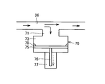
図8および図9は、実施の形態3の蓄ガス器への気相冷媒の流出入を示す模式図である。実施の形態3の冷却装置1では、蓄ガス器70内に配置された可動仕切部75を強制的に駆動するための駆動部77が設けられている点で、実施の形態1と異なっている。実施の形態3の冷却装置1は、駆動部77を備えることにより、冷媒通路36から蓄ガス器70の内部へ冷媒蒸気を積極的に移動させることができ、または、蓄ガス器70の内部から冷媒通路36へ冷媒蒸気を積極的に移動させることができる。
(Embodiment 3)
8 and 9 are schematic diagrams illustrating the inflow and outflow of the gas-phase refrigerant to the gas storage device of the third embodiment. The cooling device 1 according to the third embodiment is different from the first embodiment in that a drive unit 77 for forcibly driving the movable partition unit 75 disposed in the gas storage unit 70 is provided. . The cooling device 1 according to the third embodiment can move the refrigerant vapor from the refrigerant passage 36 to the inside of the gas accumulator 70 by providing the drive unit 77, or from the inside of the gas accumulator 70. The refrigerant vapor can be actively moved to the refrigerant passage 36.

図8および図9に示すように、可動仕切部75は、蒸気収容部73の容積を増減させる。可動仕切部75に対して冷媒通路36から離れる側に、可動仕切部75を駆動するための駆動力を発生する駆動部77が配置されている。なお、実施の形態1の蓄ガス器70では、ガス封入部74に充填された気体の内圧により可動仕切部72を移動させるためにガス封入部74は密閉空間とされたが、実施の形態3では、可動仕切部75は駆動部77により動かされるので、密閉空間のガス封入部を設けなくてもよい。   As shown in FIGS. 8 and 9, the movable partition portion 75 increases or decreases the volume of the steam storage portion 73. A drive unit 77 that generates a driving force for driving the movable partition unit 75 is disposed on the side away from the refrigerant passage 36 with respect to the movable partition unit 75. In the gas accumulator 70 of the first embodiment, the gas enclosure 74 is a sealed space in order to move the movable partition 72 by the internal pressure of the gas filled in the gas enclosure 74. Then, since the movable partition part 75 is moved by the drive part 77, it is not necessary to provide the gas enclosure part of sealed space.

動力伝達軸76は、可動仕切部75から駆動部77へ延在する。動力伝達軸76の一端は可動仕切部75に固定され、動力伝達軸76の他端は駆動部77内に配置される。動力伝達軸76は、その他端側において駆動部77から駆動力を受け、冷媒通路36に近づくまたは冷媒通路36から離れるように可動仕切部75を移動させる。駆動部77はたとえば、電気エネルギーにより動力伝達軸76を移動させることにより、動力伝達軸76を介して可動仕切部75を電気的に駆動してもよい。可動仕切部75、動力伝達軸76および駆動部77は、プランジャポンプを構成してもよい。   The power transmission shaft 76 extends from the movable partition portion 75 to the drive portion 77. One end of the power transmission shaft 76 is fixed to the movable partition portion 75, and the other end of the power transmission shaft 76 is disposed in the drive portion 77. The power transmission shaft 76 receives a driving force from the driving unit 77 on the other end side, and moves the movable partition unit 75 so as to approach the refrigerant passage 36 or leave the refrigerant passage 36. For example, the drive unit 77 may electrically drive the movable partition unit 75 via the power transmission shaft 76 by moving the power transmission shaft 76 with electric energy. The movable partition portion 75, the power transmission shaft 76, and the drive portion 77 may constitute a plunger pump.

たとえば、「エアコン運転モード」から「ヒートパイプ運転モード」への切替を感知することで、冷媒通路36への冷媒蒸気の供給が必要であると判断する。このとき駆動部77によって可動仕切部75を冷媒通路36に近づく方向に移動させ、蓄ガス器70の蒸気収容部73から気相冷媒を冷媒通路36へ圧送して、閉ループ状の冷媒の経路へ冷媒蒸気を供給する。駆動部77は、可動仕切部75を移動させることにより蒸気収容部73の容積を小さくして蓄ガス器70から冷媒蒸気を強制的に排出する、排出部として機能する。   For example, it is determined that the supply of the refrigerant vapor to the refrigerant passage 36 is necessary by detecting the switching from the “air conditioner operation mode” to the “heat pipe operation mode”. At this time, the drive part 77 moves the movable partition part 75 in a direction approaching the refrigerant passage 36 and pumps the gas-phase refrigerant from the vapor storage part 73 of the gas accumulator 70 to the refrigerant passage 36 to the closed-loop refrigerant path. Supply refrigerant vapor. The drive unit 77 functions as a discharge unit that moves the movable partition unit 75 to reduce the volume of the vapor storage unit 73 and forcibly discharge the refrigerant vapor from the gas storage unit 70.

このようにすれば、「ヒートパイプ運転モード」への切替時に、蓄ガス器70から気相冷媒を強制排出してヒートパイプを形成する冷媒の経路に気相冷媒を供給できるので、冷媒の駆動力が不足するのを抑制でき、HV機器31の冷却能力が減少してHV機器31が過熱する不具合を抑制することができる。   In this way, when switching to the “heat pipe operation mode”, the gas-phase refrigerant can be supplied to the refrigerant path that forcibly discharges the gas-phase refrigerant from the gas accumulator 70 to form the heat pipe. Insufficient power can be suppressed, and the cooling capacity of the HV device 31 can be reduced, thereby preventing the HV device 31 from overheating.

なお、これまでの実施の形態においては、HV機器31を例として車両に搭載された電気機器を冷却する冷却装置1について説明した。電気機器としては、少なくとも作動によって熱を発生させる電気機器であれば、インバータ、モータジェネレータなどの例示された電気機器に限定されるものではなく、任意の電気機器であってもよい。冷却の対象となる電気機器が複数個ある場合においては、複数の電気機器は、冷却の目標となる温度範囲が共通していることが望ましい。冷却の目標となる温度範囲は、電気機器を作動させる温度環境として適切な温度範囲である。   In the embodiments described so far, the cooling device 1 that cools the electric device mounted on the vehicle has been described using the HV device 31 as an example. The electric device is not limited to the exemplified electric device such as an inverter and a motor generator as long as it is an electric device that generates heat at least by operation, and may be any electric device. When there are a plurality of electrical devices to be cooled, it is desirable that the plurality of electrical devices have a common temperature range to be cooled. The target temperature range for cooling is a temperature range suitable as a temperature environment for operating the electrical equipment.

以上のように本発明の実施の形態について説明を行なったが、今回開示された実施の形態はすべての点で例示であって、制限的なものではないと考えられるべきである。この発明の範囲は上記した説明ではなくて特許請求の範囲によって示され、特許請求の範囲と均等の意味、および範囲内でのすべての変更が含まれることが意図される。   Although the embodiment of the present invention has been described as above, the embodiment disclosed this time should be considered as illustrative in all points and not restrictive. The scope of the present invention is defined by the terms of the claims, rather than the description above, and is intended to include any modifications within the scope and meaning equivalent to the terms of the claims.

本発明の冷却装置は、モータジェネレータおよびインバータなどの電気機器を搭載するハイブリッド車、燃料電池車、電気自動車などの車両における、車内の冷房を行なうための蒸気圧縮式冷凍サイクルを使用した電気機器の冷却に、特に有利に適用され得る。   The cooling device of the present invention is an electrical device using a vapor compression refrigeration cycle for cooling the interior of a vehicle such as a hybrid vehicle, a fuel cell vehicle, and an electric vehicle equipped with electrical devices such as a motor generator and an inverter. It can be applied particularly advantageously to cooling.

1 冷却装置、10 蒸気圧縮式冷凍サイクル、12 圧縮機、14,15,18 熱交換器、16 膨張弁、21,22,23,24,25,26,27,34,36,36a,36b 冷媒通路、30 冷却部、31 HV機器、32 冷却通路、40 気液分離器、51 連通路、52 切換弁、54,79 逆止弁、57,58 弁、60 地面、70 蓄ガス器、71 接続部、72,75 可動仕切部、73 蒸気収容部、74 ガス封入部、76 動力伝達軸、77 駆動部、78 封止材、84 付勢部材。   DESCRIPTION OF SYMBOLS 1 Cooling device, 10 Vapor compression refrigeration cycle, 12 Compressor, 14, 15, 18 Heat exchanger, 16 Expansion valve, 21, 22, 23, 24, 25, 26, 27, 34, 36, 36a, 36b Refrigerant Passage, 30 cooling section, 31 HV equipment, 32 cooling passage, 40 gas-liquid separator, 51 communication passage, 52 switching valve, 54, 79 check valve, 57, 58 valve, 60 ground, 70 gas storage, 71 connection Part, 72, 75 movable partition part, 73 steam accommodating part, 74 gas enclosing part, 76 power transmission shaft, 77 drive part, 78 sealing material, 84 biasing member.

Claims (7)

発熱源を冷却する冷却装置であって、
冷媒を循環させるための圧縮機と、
前記冷媒と外気との間で熱交換する第一熱交換器と、
前記冷媒を減圧する減圧器と、
前記冷媒と空調用空気との間で熱交換する第二熱交換器と、
前記第一熱交換器と前記減圧器との間を流れる前記冷媒を用いて前記発熱源を冷却する冷却部と、
前記冷却部で前記発熱源と熱交換して気化した気相冷媒を貯留する蓄ガス器と、を備え
前記気相冷媒は、前記圧縮機の運転時に前記蓄ガス器へ流入して前記蓄ガス器に貯留され、前記圧縮機の停止時に前記蓄ガス器から流出する、冷却装置。
A cooling device for cooling a heat source,
A compressor for circulating the refrigerant;
A first heat exchanger for exchanging heat between the refrigerant and outside air;
A decompressor for decompressing the refrigerant;
A second heat exchanger that exchanges heat between the refrigerant and air-conditioning air;
A cooling unit that cools the heat source using the refrigerant flowing between the first heat exchanger and the decompressor;
A gas storage device for storing a gas phase refrigerant vaporized by heat exchange with the heat source in the cooling unit ,
The gas-phase refrigerant, said during the compressor operation flows into the gas accumulator stored in the gas accumulator, you flowing out of the gas accumulator during stopping of the compressor, the cooling device.
前記蓄ガス器から前記気相冷媒を強制排出する排出部を備える、請求項1に記載の冷却装置。 Comprising a discharge portion for forcibly discharging the gas-phase refrigerant from the gas accumulator, the cooling device according to claim 1. 前記蓄ガス器から流出する前記気相冷媒の前記冷却部への流れを禁止する逆止弁を備える、請求項1または請求項に記載の冷却装置。 Comprises a check valve prohibiting flow to the cooling part of the gas-phase refrigerant flowing out of the gas accumulator, the cooling device according to claim 1 or claim 2. 前記第一熱交換器と前記減圧器との間の前記冷媒の経路において並列に接続された第一通路と第二通路とを備え、
前記発熱源は、前記第二通路を流れる前記冷媒により冷却される、請求項1から請求項のいずれかに記載の冷却装置。
A first passage and a second passage connected in parallel in the refrigerant path between the first heat exchanger and the decompressor;
The cooling device according to any one of claims 1 to 3 , wherein the heat generation source is cooled by the refrigerant flowing through the second passage.
前記圧縮機と前記第一熱交換器との間を前記冷媒が流れる第三通路と、
前記第二通路の前記冷却部に対し前記減圧器に近接する側と前記第三通路とを連通する連通路と、を備える、請求項に記載の冷却装置。
A third passage through which the refrigerant flows between the compressor and the first heat exchanger;
The cooling device according to claim 4 , further comprising: a communication passage that communicates the third passage with a side of the second passage that is close to the decompressor.
前記第二通路の前記冷却部に対し前記減圧器に近接する側と、前記連通路と、の連通状態を切り換える、切換弁を備える、請求項に記載の冷却装置。 The cooling device according to claim 5 , further comprising a switching valve that switches a communication state between the side of the second passage closer to the decompressor and the communication passage. 前記圧縮機の停止時に前記冷媒が前記連通路へ流れるように、前記切換弁の開閉を設定する、請求項に記載の冷却装置。 The cooling device according to claim 6 , wherein opening and closing of the switching valve is set so that the refrigerant flows into the communication path when the compressor is stopped.
JP2011188837A 2011-08-31 2011-08-31 Cooling system Active JP5852368B2 (en)

Priority Applications (5)

Application Number Priority Date Filing Date Title
JP2011188837A JP5852368B2 (en) 2011-08-31 2011-08-31 Cooling system
US14/241,268 US9951973B2 (en) 2011-08-31 2012-08-30 Cooling system utilizing a portion of the liquid refrigerant from the condenser
CN201280042233.7A CN103764418B (en) 2011-08-31 2012-08-30 Cooling system
EP12775840.7A EP2750908B8 (en) 2011-08-31 2012-08-30 Cooling system
PCT/IB2012/001676 WO2013030657A1 (en) 2011-08-31 2012-08-30 Cooling system

Applications Claiming Priority (1)

Application Number Priority Date Filing Date Title
JP2011188837A JP5852368B2 (en) 2011-08-31 2011-08-31 Cooling system

Publications (2)

Publication Number Publication Date
JP2013049366A JP2013049366A (en) 2013-03-14
JP5852368B2 true JP5852368B2 (en) 2016-02-03

Family

ID=47071412

Family Applications (1)

Application Number Title Priority Date Filing Date
JP2011188837A Active JP5852368B2 (en) 2011-08-31 2011-08-31 Cooling system

Country Status (5)

Country Link
US (1) US9951973B2 (en)
EP (1) EP2750908B8 (en)
JP (1) JP5852368B2 (en)
CN (1) CN103764418B (en)
WO (1) WO2013030657A1 (en)

Families Citing this family (8)

* Cited by examiner, † Cited by third party
Publication number Priority date Publication date Assignee Title
JP5798402B2 (en) * 2011-08-01 2015-10-21 トヨタ自動車株式会社 Cooling system
CN105684487B (en) 2013-11-01 2020-09-04 三菱电机株式会社 Communication system
CN104640420A (en) * 2013-11-21 2015-05-20 珠海格力电器股份有限公司 Cooling system of heating power device
DE102014226346A1 (en) * 2014-12-18 2016-06-23 Bayerische Motoren Werke Aktiengesellschaft Heating system for an electric or hybrid vehicle
US10375564B2 (en) * 2015-01-14 2019-08-06 Lg Electronics Inc. Method for updating area in wireless communication system, and device therefor
EP3501210A1 (en) * 2016-08-16 2019-06-26 Convida Wireless, LLC Keeping the ue awake
KR20210026705A (en) * 2019-09-02 2021-03-10 현대자동차주식회사 Heat pump system for vehicle
US11267318B2 (en) * 2019-11-26 2022-03-08 Ford Global Technologies, Llc Vapor injection heat pump system and controls

Family Cites Families (24)

* Cited by examiner, † Cited by third party
Publication number Priority date Publication date Assignee Title
US2795374A (en) * 1953-08-13 1957-06-11 Du Pont Fluid flow pulsation damping
US3095012A (en) * 1957-08-13 1963-06-25 Westinghouse Electric Corp Pressure controlling system
US3594131A (en) * 1969-11-10 1971-07-20 Universal Oil Prod Co Catalytic converter
US3838977A (en) * 1972-02-24 1974-10-01 Ethyl Corp Catalytic muffler
NL171084C (en) * 1972-09-13 1983-02-01 Reintjes Eisenwerke HYDRAULICALLY OPERABLE FLAP COUPLER, IN PARTICULAR FOR SHIP-REVERSING GEARS.
US3987708A (en) * 1975-03-10 1976-10-26 The United States Of America As Represented By The Secretary Of The Navy Depth insensitive accumulator for undersea hydraulic systems
US4562036A (en) * 1983-08-26 1985-12-31 The United States Of America As Represented By The United States Department Of Energy Shock wave absorber having apertured plate
JPH02266101A (en) * 1989-04-05 1990-10-30 Nhk Spring Co Ltd Accumulator
JPH1054616A (en) * 1996-08-14 1998-02-24 Daikin Ind Ltd Air conditioner
JP3952545B2 (en) * 1997-07-24 2007-08-01 株式会社デンソー Air conditioner for vehicles
JP2000073763A (en) * 1998-08-26 2000-03-07 Nissan Motor Co Ltd Cooling system of hybrid powered automatic
JP4078812B2 (en) * 2000-04-26 2008-04-23 株式会社デンソー Refrigeration cycle equipment
JP3906724B2 (en) 2002-03-29 2007-04-18 株式会社デンソー Air conditioner for vehicles
JP3928470B2 (en) * 2002-04-26 2007-06-13 株式会社デンソー Air conditioner for vehicles
JP4156353B2 (en) 2002-12-02 2008-09-24 株式会社テージーケー Refrigeration system and operation method thereof
JP2005082066A (en) * 2003-09-10 2005-03-31 Toyota Motor Corp Cooling system
JP2005090862A (en) 2003-09-17 2005-04-07 Toyota Motor Corp Cooling system
JP2006029614A (en) * 2004-07-13 2006-02-02 Nippon Steel Corp Vapor compression type heat pump system
JP4459776B2 (en) * 2004-10-18 2010-04-28 三菱電機株式会社 Heat pump device and outdoor unit of heat pump device
JP2007069733A (en) 2005-09-07 2007-03-22 Valeo Thermal Systems Japan Corp Heating element cooling system using air conditioner for vehicle
JP4940877B2 (en) * 2006-10-10 2012-05-30 トヨタ自動車株式会社 Air conditioning control system
JP2011001048A (en) 2009-05-19 2011-01-06 Toyota Industries Corp Air-conditioning system for vehicle
DE102009056027B4 (en) * 2009-09-11 2014-01-16 Audi Ag Vehicle, in particular electric vehicle
JP5396246B2 (en) * 2009-11-18 2014-01-22 株式会社日立製作所 Air conditioner for vehicles

Also Published As

Publication number Publication date
US9951973B2 (en) 2018-04-24
WO2013030657A1 (en) 2013-03-07
US20150000331A1 (en) 2015-01-01
EP2750908B1 (en) 2015-01-07
CN103764418B (en) 2016-02-10
CN103764418A (en) 2014-04-30
JP2013049366A (en) 2013-03-14
EP2750908B8 (en) 2015-02-18
EP2750908A1 (en) 2014-07-09

Similar Documents

Publication Publication Date Title
JP5798402B2 (en) Cooling system
JP5522275B2 (en) Cooling system
JP5748000B2 (en) Cooling device for electrical equipment
JP5989328B2 (en) Heat exchanger
JP5798416B2 (en) Switching valve and cooling device
JP5852368B2 (en) Cooling system
JP5815284B2 (en) Cooling system
US9681590B2 (en) Cooling system with controlled apportioning of the cooled high pressure refrigerant between the condenser and the expansion valve
JP5531045B2 (en) Cooling system
JP5737424B2 (en) Cooling device for electrical equipment
JP5669778B2 (en) Cooling device and vehicle including the same
WO2013051114A1 (en) Control method for cooling apparatus
JP2013023186A (en) Cooling apparatus
JP2014029232A (en) Cooling device
JP2012245857A (en) Cooling apparatus, and method and device for controlling the same
JP2012245856A (en) Cooling system
JP2012163240A (en) Cooling apparatus
JP2014051118A (en) Cooling device
JP5618011B2 (en) Control method of cooling device
JP5917966B2 (en) Cooling device and vehicle including the same
JP2014059122A (en) Rotary valve, and cooling device
JP2014088997A (en) Cooling device
JP2014081127A (en) Cooling apparatus and control method for the same
JP2014088996A (en) Cooling apparatus
JP2014061787A (en) Cooling device of electric apparatus

Legal Events

Date Code Title Description
A621 Written request for application examination

Free format text: JAPANESE INTERMEDIATE CODE: A621

Effective date: 20140704

A977 Report on retrieval

Free format text: JAPANESE INTERMEDIATE CODE: A971007

Effective date: 20150330

A131 Notification of reasons for refusal

Free format text: JAPANESE INTERMEDIATE CODE: A131

Effective date: 20150331

A521 Request for written amendment filed

Free format text: JAPANESE INTERMEDIATE CODE: A523

Effective date: 20150525

TRDD Decision of grant or rejection written
A01 Written decision to grant a patent or to grant a registration (utility model)

Free format text: JAPANESE INTERMEDIATE CODE: A01

Effective date: 20151117

A61 First payment of annual fees (during grant procedure)

Free format text: JAPANESE INTERMEDIATE CODE: A61

Effective date: 20151204

R151 Written notification of patent or utility model registration

Ref document number: 5852368

Country of ref document: JP

Free format text: JAPANESE INTERMEDIATE CODE: R151

R250 Receipt of annual fees

Free format text: JAPANESE INTERMEDIATE CODE: R250

R250 Receipt of annual fees

Free format text: JAPANESE INTERMEDIATE CODE: R250

R250 Receipt of annual fees

Free format text: JAPANESE INTERMEDIATE CODE: R250