JP4940877B2 - Air conditioning control system - Google Patents
Air conditioning control system Download PDFInfo
- Publication number
- JP4940877B2 JP4940877B2 JP2006276841A JP2006276841A JP4940877B2 JP 4940877 B2 JP4940877 B2 JP 4940877B2 JP 2006276841 A JP2006276841 A JP 2006276841A JP 2006276841 A JP2006276841 A JP 2006276841A JP 4940877 B2 JP4940877 B2 JP 4940877B2
- Authority
- JP
- Japan
- Prior art keywords
- fuel cell
- coolant
- heat exchanger
- conditioning control
- air
- Prior art date
- Legal status (The legal status is an assumption and is not a legal conclusion. Google has not performed a legal analysis and makes no representation as to the accuracy of the status listed.)
- Expired - Fee Related
Links
- 238000004378 air conditioning Methods 0.000 title claims description 66
- 239000000446 fuel Substances 0.000 claims description 139
- 239000002826 coolant Substances 0.000 claims description 72
- 238000001816 cooling Methods 0.000 claims description 53
- 238000010438 heat treatment Methods 0.000 claims description 50
- 239000003507 refrigerant Substances 0.000 claims description 44
- 239000007789 gas Substances 0.000 claims description 11
- 239000002737 fuel gas Substances 0.000 claims description 10
- 239000007800 oxidant agent Substances 0.000 claims description 10
- 230000001590 oxidative effect Effects 0.000 claims description 10
- 210000004027 cell Anatomy 0.000 description 124
- 238000000034 method Methods 0.000 description 12
- 230000001172 regenerating effect Effects 0.000 description 8
- 239000003054 catalyst Substances 0.000 description 6
- 239000000498 cooling water Substances 0.000 description 5
- 239000001257 hydrogen Substances 0.000 description 5
- 229910052739 hydrogen Inorganic materials 0.000 description 5
- 238000009792 diffusion process Methods 0.000 description 4
- 239000003792 electrolyte Substances 0.000 description 4
- 239000002918 waste heat Substances 0.000 description 4
- UFHFLCQGNIYNRP-UHFFFAOYSA-N Hydrogen Chemical compound [H][H] UFHFLCQGNIYNRP-UHFFFAOYSA-N 0.000 description 3
- 239000000110 cooling liquid Substances 0.000 description 3
- -1 hydrogen ions Chemical class 0.000 description 3
- 150000002500 ions Chemical class 0.000 description 3
- 238000010248 power generation Methods 0.000 description 3
- 238000003487 electrochemical reaction Methods 0.000 description 2
- 230000020169 heat generation Effects 0.000 description 2
- 239000007791 liquid phase Substances 0.000 description 2
- 238000007254 oxidation reaction Methods 0.000 description 2
- 238000006722 reduction reaction Methods 0.000 description 2
- 238000010792 warming Methods 0.000 description 2
- XLYOFNOQVPJJNP-UHFFFAOYSA-N water Substances O XLYOFNOQVPJJNP-UHFFFAOYSA-N 0.000 description 2
- 210000005056 cell body Anatomy 0.000 description 1
- 230000006835 compression Effects 0.000 description 1
- 238000007906 compression Methods 0.000 description 1
- 238000010586 diagram Methods 0.000 description 1
- 238000005265 energy consumption Methods 0.000 description 1
- 239000012535 impurity Substances 0.000 description 1
- 238000010030 laminating Methods 0.000 description 1
- 239000007788 liquid Substances 0.000 description 1
- 239000012071 phase Substances 0.000 description 1
- 238000011144 upstream manufacturing Methods 0.000 description 1
Images

Classifications
-
- B—PERFORMING OPERATIONS; TRANSPORTING
- B60—VEHICLES IN GENERAL
- B60H—ARRANGEMENTS OF HEATING, COOLING, VENTILATING OR OTHER AIR-TREATING DEVICES SPECIALLY ADAPTED FOR PASSENGER OR GOODS SPACES OF VEHICLES
- B60H1/00—Heating, cooling or ventilating [HVAC] devices
- B60H1/00357—Air-conditioning arrangements specially adapted for particular vehicles
- B60H1/00385—Air-conditioning arrangements specially adapted for particular vehicles for vehicles having an electrical drive, e.g. hybrid or fuel cell
-
- B—PERFORMING OPERATIONS; TRANSPORTING
- B60—VEHICLES IN GENERAL
- B60H—ARRANGEMENTS OF HEATING, COOLING, VENTILATING OR OTHER AIR-TREATING DEVICES SPECIALLY ADAPTED FOR PASSENGER OR GOODS SPACES OF VEHICLES
- B60H1/00—Heating, cooling or ventilating [HVAC] devices
- B60H1/02—Heating, cooling or ventilating [HVAC] devices the heat being derived from the propulsion plant
- B60H1/14—Heating, cooling or ventilating [HVAC] devices the heat being derived from the propulsion plant otherwise than from cooling liquid of the plant, e.g. heat from the grease oil, the brakes, the transmission unit
- B60H1/143—Heating, cooling or ventilating [HVAC] devices the heat being derived from the propulsion plant otherwise than from cooling liquid of the plant, e.g. heat from the grease oil, the brakes, the transmission unit the heat being derived from cooling an electric component, e.g. electric motors, electric circuits, fuel cells or batteries
-
- B—PERFORMING OPERATIONS; TRANSPORTING
- B60—VEHICLES IN GENERAL
- B60K—ARRANGEMENT OR MOUNTING OF PROPULSION UNITS OR OF TRANSMISSIONS IN VEHICLES; ARRANGEMENT OR MOUNTING OF PLURAL DIVERSE PRIME-MOVERS IN VEHICLES; AUXILIARY DRIVES FOR VEHICLES; INSTRUMENTATION OR DASHBOARDS FOR VEHICLES; ARRANGEMENTS IN CONNECTION WITH COOLING, AIR INTAKE, GAS EXHAUST OR FUEL SUPPLY OF PROPULSION UNITS IN VEHICLES
- B60K1/00—Arrangement or mounting of electrical propulsion units
- B60K1/04—Arrangement or mounting of electrical propulsion units of the electric storage means for propulsion
-
- B—PERFORMING OPERATIONS; TRANSPORTING
- B60—VEHICLES IN GENERAL
- B60L—PROPULSION OF ELECTRICALLY-PROPELLED VEHICLES; SUPPLYING ELECTRIC POWER FOR AUXILIARY EQUIPMENT OF ELECTRICALLY-PROPELLED VEHICLES; ELECTRODYNAMIC BRAKE SYSTEMS FOR VEHICLES IN GENERAL; MAGNETIC SUSPENSION OR LEVITATION FOR VEHICLES; MONITORING OPERATING VARIABLES OF ELECTRICALLY-PROPELLED VEHICLES; ELECTRIC SAFETY DEVICES FOR ELECTRICALLY-PROPELLED VEHICLES
- B60L1/00—Supplying electric power to auxiliary equipment of vehicles
- B60L1/003—Supplying electric power to auxiliary equipment of vehicles to auxiliary motors, e.g. for pumps, compressors
-
- B—PERFORMING OPERATIONS; TRANSPORTING
- B60—VEHICLES IN GENERAL
- B60L—PROPULSION OF ELECTRICALLY-PROPELLED VEHICLES; SUPPLYING ELECTRIC POWER FOR AUXILIARY EQUIPMENT OF ELECTRICALLY-PROPELLED VEHICLES; ELECTRODYNAMIC BRAKE SYSTEMS FOR VEHICLES IN GENERAL; MAGNETIC SUSPENSION OR LEVITATION FOR VEHICLES; MONITORING OPERATING VARIABLES OF ELECTRICALLY-PROPELLED VEHICLES; ELECTRIC SAFETY DEVICES FOR ELECTRICALLY-PROPELLED VEHICLES
- B60L58/00—Methods or circuit arrangements for monitoring or controlling batteries or fuel cells, specially adapted for electric vehicles
- B60L58/30—Methods or circuit arrangements for monitoring or controlling batteries or fuel cells, specially adapted for electric vehicles for monitoring or controlling fuel cells
- B60L58/32—Methods or circuit arrangements for monitoring or controlling batteries or fuel cells, specially adapted for electric vehicles for monitoring or controlling fuel cells for controlling the temperature of fuel cells, e.g. by controlling the electric load
- B60L58/33—Methods or circuit arrangements for monitoring or controlling batteries or fuel cells, specially adapted for electric vehicles for monitoring or controlling fuel cells for controlling the temperature of fuel cells, e.g. by controlling the electric load by cooling
-
- B—PERFORMING OPERATIONS; TRANSPORTING
- B60—VEHICLES IN GENERAL
- B60L—PROPULSION OF ELECTRICALLY-PROPELLED VEHICLES; SUPPLYING ELECTRIC POWER FOR AUXILIARY EQUIPMENT OF ELECTRICALLY-PROPELLED VEHICLES; ELECTRODYNAMIC BRAKE SYSTEMS FOR VEHICLES IN GENERAL; MAGNETIC SUSPENSION OR LEVITATION FOR VEHICLES; MONITORING OPERATING VARIABLES OF ELECTRICALLY-PROPELLED VEHICLES; ELECTRIC SAFETY DEVICES FOR ELECTRICALLY-PROPELLED VEHICLES
- B60L58/00—Methods or circuit arrangements for monitoring or controlling batteries or fuel cells, specially adapted for electric vehicles
- B60L58/30—Methods or circuit arrangements for monitoring or controlling batteries or fuel cells, specially adapted for electric vehicles for monitoring or controlling fuel cells
- B60L58/32—Methods or circuit arrangements for monitoring or controlling batteries or fuel cells, specially adapted for electric vehicles for monitoring or controlling fuel cells for controlling the temperature of fuel cells, e.g. by controlling the electric load
- B60L58/34—Methods or circuit arrangements for monitoring or controlling batteries or fuel cells, specially adapted for electric vehicles for monitoring or controlling fuel cells for controlling the temperature of fuel cells, e.g. by controlling the electric load by heating
-
- B—PERFORMING OPERATIONS; TRANSPORTING
- B60—VEHICLES IN GENERAL
- B60L—PROPULSION OF ELECTRICALLY-PROPELLED VEHICLES; SUPPLYING ELECTRIC POWER FOR AUXILIARY EQUIPMENT OF ELECTRICALLY-PROPELLED VEHICLES; ELECTRODYNAMIC BRAKE SYSTEMS FOR VEHICLES IN GENERAL; MAGNETIC SUSPENSION OR LEVITATION FOR VEHICLES; MONITORING OPERATING VARIABLES OF ELECTRICALLY-PROPELLED VEHICLES; ELECTRIC SAFETY DEVICES FOR ELECTRICALLY-PROPELLED VEHICLES
- B60L58/00—Methods or circuit arrangements for monitoring or controlling batteries or fuel cells, specially adapted for electric vehicles
- B60L58/40—Methods or circuit arrangements for monitoring or controlling batteries or fuel cells, specially adapted for electric vehicles for controlling a combination of batteries and fuel cells
-
- H—ELECTRICITY
- H01—ELECTRIC ELEMENTS
- H01M—PROCESSES OR MEANS, e.g. BATTERIES, FOR THE DIRECT CONVERSION OF CHEMICAL ENERGY INTO ELECTRICAL ENERGY
- H01M8/00—Fuel cells; Manufacture thereof
- H01M8/04—Auxiliary arrangements, e.g. for control of pressure or for circulation of fluids
- H01M8/04007—Auxiliary arrangements, e.g. for control of pressure or for circulation of fluids related to heat exchange
- H01M8/04029—Heat exchange using liquids
-
- H—ELECTRICITY
- H01—ELECTRIC ELEMENTS
- H01M—PROCESSES OR MEANS, e.g. BATTERIES, FOR THE DIRECT CONVERSION OF CHEMICAL ENERGY INTO ELECTRICAL ENERGY
- H01M8/00—Fuel cells; Manufacture thereof
- H01M8/04—Auxiliary arrangements, e.g. for control of pressure or for circulation of fluids
- H01M8/04223—Auxiliary arrangements, e.g. for control of pressure or for circulation of fluids during start-up or shut-down; Depolarisation or activation, e.g. purging; Means for short-circuiting defective fuel cells
- H01M8/04228—Auxiliary arrangements, e.g. for control of pressure or for circulation of fluids during start-up or shut-down; Depolarisation or activation, e.g. purging; Means for short-circuiting defective fuel cells during shut-down
-
- B—PERFORMING OPERATIONS; TRANSPORTING
- B60—VEHICLES IN GENERAL
- B60K—ARRANGEMENT OR MOUNTING OF PROPULSION UNITS OR OF TRANSMISSIONS IN VEHICLES; ARRANGEMENT OR MOUNTING OF PLURAL DIVERSE PRIME-MOVERS IN VEHICLES; AUXILIARY DRIVES FOR VEHICLES; INSTRUMENTATION OR DASHBOARDS FOR VEHICLES; ARRANGEMENTS IN CONNECTION WITH COOLING, AIR INTAKE, GAS EXHAUST OR FUEL SUPPLY OF PROPULSION UNITS IN VEHICLES
- B60K1/00—Arrangement or mounting of electrical propulsion units
- B60K2001/003—Arrangement or mounting of electrical propulsion units with means for cooling the electrical propulsion units
- B60K2001/005—Arrangement or mounting of electrical propulsion units with means for cooling the electrical propulsion units the electric storage means
-
- B—PERFORMING OPERATIONS; TRANSPORTING
- B60—VEHICLES IN GENERAL
- B60Y—INDEXING SCHEME RELATING TO ASPECTS CROSS-CUTTING VEHICLE TECHNOLOGY
- B60Y2200/00—Type of vehicle
- B60Y2200/90—Vehicles comprising electric prime movers
- B60Y2200/91—Electric vehicles
-
- B—PERFORMING OPERATIONS; TRANSPORTING
- B60—VEHICLES IN GENERAL
- B60Y—INDEXING SCHEME RELATING TO ASPECTS CROSS-CUTTING VEHICLE TECHNOLOGY
- B60Y2200/00—Type of vehicle
- B60Y2200/90—Vehicles comprising electric prime movers
- B60Y2200/92—Hybrid vehicles
-
- B—PERFORMING OPERATIONS; TRANSPORTING
- B60—VEHICLES IN GENERAL
- B60Y—INDEXING SCHEME RELATING TO ASPECTS CROSS-CUTTING VEHICLE TECHNOLOGY
- B60Y2306/00—Other features of vehicle sub-units
- B60Y2306/05—Cooling
-
- H—ELECTRICITY
- H01—ELECTRIC ELEMENTS
- H01M—PROCESSES OR MEANS, e.g. BATTERIES, FOR THE DIRECT CONVERSION OF CHEMICAL ENERGY INTO ELECTRICAL ENERGY
- H01M2250/00—Fuel cells for particular applications; Specific features of fuel cell system
- H01M2250/20—Fuel cells in motive systems, e.g. vehicle, ship, plane
-
- H—ELECTRICITY
- H01—ELECTRIC ELEMENTS
- H01M—PROCESSES OR MEANS, e.g. BATTERIES, FOR THE DIRECT CONVERSION OF CHEMICAL ENERGY INTO ELECTRICAL ENERGY
- H01M2250/00—Fuel cells for particular applications; Specific features of fuel cell system
- H01M2250/40—Combination of fuel cells with other energy production systems
- H01M2250/405—Cogeneration of heat or hot water
-
- Y—GENERAL TAGGING OF NEW TECHNOLOGICAL DEVELOPMENTS; GENERAL TAGGING OF CROSS-SECTIONAL TECHNOLOGIES SPANNING OVER SEVERAL SECTIONS OF THE IPC; TECHNICAL SUBJECTS COVERED BY FORMER USPC CROSS-REFERENCE ART COLLECTIONS [XRACs] AND DIGESTS
- Y02—TECHNOLOGIES OR APPLICATIONS FOR MITIGATION OR ADAPTATION AGAINST CLIMATE CHANGE
- Y02B—CLIMATE CHANGE MITIGATION TECHNOLOGIES RELATED TO BUILDINGS, e.g. HOUSING, HOUSE APPLIANCES OR RELATED END-USER APPLICATIONS
- Y02B90/00—Enabling technologies or technologies with a potential or indirect contribution to GHG emissions mitigation
- Y02B90/10—Applications of fuel cells in buildings
-
- Y—GENERAL TAGGING OF NEW TECHNOLOGICAL DEVELOPMENTS; GENERAL TAGGING OF CROSS-SECTIONAL TECHNOLOGIES SPANNING OVER SEVERAL SECTIONS OF THE IPC; TECHNICAL SUBJECTS COVERED BY FORMER USPC CROSS-REFERENCE ART COLLECTIONS [XRACs] AND DIGESTS
- Y02—TECHNOLOGIES OR APPLICATIONS FOR MITIGATION OR ADAPTATION AGAINST CLIMATE CHANGE
- Y02E—REDUCTION OF GREENHOUSE GAS [GHG] EMISSIONS, RELATED TO ENERGY GENERATION, TRANSMISSION OR DISTRIBUTION
- Y02E60/00—Enabling technologies; Technologies with a potential or indirect contribution to GHG emissions mitigation
- Y02E60/30—Hydrogen technology
- Y02E60/50—Fuel cells
-
- Y—GENERAL TAGGING OF NEW TECHNOLOGICAL DEVELOPMENTS; GENERAL TAGGING OF CROSS-SECTIONAL TECHNOLOGIES SPANNING OVER SEVERAL SECTIONS OF THE IPC; TECHNICAL SUBJECTS COVERED BY FORMER USPC CROSS-REFERENCE ART COLLECTIONS [XRACs] AND DIGESTS
- Y02—TECHNOLOGIES OR APPLICATIONS FOR MITIGATION OR ADAPTATION AGAINST CLIMATE CHANGE
- Y02T—CLIMATE CHANGE MITIGATION TECHNOLOGIES RELATED TO TRANSPORTATION
- Y02T10/00—Road transport of goods or passengers
- Y02T10/60—Other road transportation technologies with climate change mitigation effect
- Y02T10/70—Energy storage systems for electromobility, e.g. batteries
-
- Y—GENERAL TAGGING OF NEW TECHNOLOGICAL DEVELOPMENTS; GENERAL TAGGING OF CROSS-SECTIONAL TECHNOLOGIES SPANNING OVER SEVERAL SECTIONS OF THE IPC; TECHNICAL SUBJECTS COVERED BY FORMER USPC CROSS-REFERENCE ART COLLECTIONS [XRACs] AND DIGESTS
- Y02—TECHNOLOGIES OR APPLICATIONS FOR MITIGATION OR ADAPTATION AGAINST CLIMATE CHANGE
- Y02T—CLIMATE CHANGE MITIGATION TECHNOLOGIES RELATED TO TRANSPORTATION
- Y02T90/00—Enabling technologies or technologies with a potential or indirect contribution to GHG emissions mitigation
- Y02T90/40—Application of hydrogen technology to transportation, e.g. using fuel cells
Description
本発明は、燃料電池を利用した空調制御システムに関する。 The present invention relates to an air conditioning control system using a fuel cell.
燃料電池は、低温時では十分な発電能力を得ることができない。このため、燃料電池の始動時などの低温時において、燃料電池の電力でその冷却水を加熱して燃料電池を暖機する技術がある(例えば、特許文献1参照)。また、燃料電池システムには、燃料電池を運転に適した温度に保つために、冷却水を循環させて、燃料電池で生じた不要な熱をラジエータで放熱する冷却装置が設けられる。 A fuel cell cannot obtain sufficient power generation capability at low temperatures. For this reason, there is a technique for warming up the fuel cell by heating the cooling water with the electric power of the fuel cell at a low temperature such as when the fuel cell is started (see, for example, Patent Document 1). Further, in order to keep the fuel cell at a temperature suitable for operation, the fuel cell system is provided with a cooling device that circulates cooling water and radiates unnecessary heat generated in the fuel cell with a radiator.
一方、燃料電池をその動力源として利用する移動体(例えば、ハイブリッド自動車や電気自動車)には、室内の冷暖房を行う空調制御装置が搭載される。空調制御装置には、例えば、低温側の熱を高温側に移動させる蒸気圧縮式ヒートポンプを利用するものがある(例えば、特許文献2参照)。 On the other hand, an air conditioning control device that cools and heats a room is mounted on a mobile body (for example, a hybrid vehicle or an electric vehicle) that uses a fuel cell as a power source. Some air conditioning control devices use, for example, a vapor compression heat pump that moves low-temperature heat to a high-temperature side (see, for example, Patent Document 2).
燃料電池システムと空調制御装置とを独立したシステムとして移動体に搭載すると、部品点数の増加、重量の増大、エネルギーのロスといった問題が生ずる。これらは、移動体の燃費が悪化する一要因となる。また、移動体への搭載スペースには限りがある。 When the fuel cell system and the air conditioning control device are mounted on a moving body as independent systems, problems such as an increase in the number of components, an increase in weight, and energy loss occur. These are factors that deteriorate the fuel consumption of the moving body. Moreover, there is a limit to the space for mounting on a moving body.
そこで、特許文献3〜7には、燃料電池システムで生じる熱を空調制御装置で利用したり、廃熱したりする技術が提案されている。例えば、燃料電池スタックの発生熱を暖房用熱交換器により回収して暖房装置の熱源として利用する技術がある(例えば、特許文献3参照)。また、燃料電池の冷却水をヒータコアに通水して暖房を行う車両用空調装置において、燃料電池で発生した燃料電池で不要な熱量が空調に必要な熱量よりも小さいときは、不足する熱量を補うように電気ヒータを発熱制御する技術がある(例えば、特許文献4参照)。また、燃料電池本体からの余った熱を空調機システムが備える放熱器で大気に放出させる技術がある(例えば、特許文献5参照)。また、回生ブレーキで発生する余剰電力で燃料電池の冷却水を加熱することで余剰電力を消費し、燃料電池の冷却水の熱を空調に利用するシステムがある(例えば、特許文献6参照)。 Therefore, Patent Documents 3 to 7 propose techniques for using heat generated in the fuel cell system in an air conditioning control device or for waste heat. For example, there is a technique in which the heat generated by the fuel cell stack is recovered by a heating heat exchanger and used as a heat source of a heating device (see, for example, Patent Document 3). In a vehicle air conditioner that heats fuel cell cooling water through a heater core, if the amount of heat generated in the fuel cell is less than the amount of heat required for air conditioning, the amount of heat that is insufficient is reduced. There is a technique for controlling heat generation of an electric heater so as to compensate (for example, see Patent Document 4). In addition, there is a technique in which surplus heat from the fuel cell body is released to the atmosphere with a radiator provided in the air conditioner system (see, for example, Patent Document 5). Further, there is a system that consumes surplus power by heating the cooling water of the fuel cell with surplus power generated by the regenerative brake, and uses the heat of the cooling water of the fuel cell for air conditioning (see, for example, Patent Document 6).
ところで、燃料電池の冷却装置と空調制御装置とを複合化させたシステムでは、燃料電池の必要出力が低くなった際に燃料電池を間欠運転することがある。その場合、空調制御装置のエアコンプレッサの周辺温度が高くなり、空調制御装置に不具合が生ずる場合があった。エアコンプレッサの周辺温度を低く保つためには、空調制御装置側に燃料電池の冷却装置で用いられる冷却液を循環させるための大型の循環ポンプを備える必要があった。 By the way, in a system in which a fuel cell cooling device and an air conditioning control device are combined, the fuel cell may be intermittently operated when the required output of the fuel cell becomes low. In that case, the ambient temperature of the air compressor of the air-conditioning control device becomes high, and a problem may occur in the air-conditioning control device. In order to keep the ambient temperature of the air compressor low, it is necessary to provide a large circulation pump for circulating the coolant used in the fuel cell cooling device on the air conditioning control device side.
本発明は、燃料電池に冷却液をメイン循環ポンプにより循環させることによって当該燃料電池の冷却を行う冷却装置と、車両の車室内の空調を制御する空調制御装置と、を含み、前記冷却装置と前記空調制御装置との間において熱交換が可能である空調制御システムであって、前記燃料電池を間欠運転する際に、前記メイン循環ポンプを動作させることを特徴とする。 The present invention includes a cooling device that cools the fuel cell by circulating a coolant in the fuel cell by a main circulation pump, and an air conditioning control device that controls air conditioning in a vehicle interior of the vehicle. An air conditioning control system capable of exchanging heat with the air conditioning control device, wherein the main circulation pump is operated when the fuel cell is intermittently operated.
例えば、前記燃料電池への燃料ガス及び酸化剤ガスの少なくとも1つの供給を停止している間、前記メイン循環ポンプを動作させ続ける。 For example, the main circulation pump is continuously operated while the supply of at least one of the fuel gas and the oxidant gas to the fuel cell is stopped.
また、前記冷却装置と前記空調制御装置との間で熱交換を行う熱交換器と、前記冷却装置から前記熱交換器へ冷却液を循環させる状態と、前記冷却装置とは独立に前記熱交換器へ冷却液を循環させる状態と、を切り替える三方弁と、前記冷却装置とは独立に前記熱交換器へ冷却液を循環させるサブ循環ポンプと、を備え、前記メイン循環ポンプの出力定格は、前記サブ循環ポンプの出力定格の2倍以上であることが好適である。 In addition, a heat exchanger that exchanges heat between the cooling device and the air conditioning control device, a state in which a coolant is circulated from the cooling device to the heat exchanger, and the heat exchange independently of the cooling device. A three-way valve that switches between a state in which the coolant is circulated to the condenser and a sub-circulation pump that circulates the coolant to the heat exchanger independently of the cooling device, and the output rating of the main circulation pump is It is preferable that the output rating of the sub-circulation pump is twice or more.
また、前記冷却装置と前記空調制御装置との間で熱交換を行う熱交換器と、前記冷却装置から前記熱交換器へ冷却液を循環させる状態と、前記冷却装置とは独立に前記熱交換器へ冷却液を循環させる状態と、を切り替える三方弁と、前記冷却装置とは独立に前記熱交換器へ冷却液を循環させるサブ循環ポンプと、を備え、前記メイン循環ポンプの最大出力流量は、前記サブ循環ポンプの最大出力流量の10倍以上であることが好適である。 In addition, a heat exchanger that exchanges heat between the cooling device and the air conditioning control device, a state in which a coolant is circulated from the cooling device to the heat exchanger, and the heat exchange independently of the cooling device. A three-way valve that switches between a state in which the coolant is circulated to the cooler and a sub-circulation pump that circulates the coolant to the heat exchanger independently of the cooling device, and the maximum output flow rate of the main circulation pump is The maximum output flow rate of the sub-circulation pump is preferably 10 times or more.
本発明によれば、燃料電池の冷却装置と空調制御装置とを複合化させた空調制御システムにおいて、空調制御装置側に大型の冷却液循環ポンプを備える必要なく、燃料電池を間欠運転した場合に空調制御装置のエアコンプレッサの温度の上昇を抑制することができる。 According to the present invention, in the air conditioning control system in which the fuel cell cooling device and the air conditioning control device are combined, there is no need to provide a large coolant circulation pump on the air conditioning control device side, and the fuel cell is operated intermittently. An increase in the temperature of the air compressor of the air conditioning control device can be suppressed.
〔構成〕
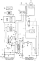
図1は、本発明における空調制御システムの構成を示すブロック図である。空調制御システムは、燃料電池システム及び空調制御装置を含んで構成される。図1には、車両に搭載された燃料電池システム及び空調制御装置が示されている。燃料電池システムは、車両の駆動力となる電力を発電するものである。また、空調制御装置は、車両の室内の温度を調整するためのものである。
〔Constitution〕
FIG. 1 is a block diagram showing a configuration of an air conditioning control system according to the present invention. The air conditioning control system includes a fuel cell system and an air conditioning control device . FIG. 1 shows a fuel cell system and an air conditioning control device mounted on a vehicle. The fuel cell system generates electric power as a driving force for a vehicle. The air conditioning control device is for adjusting the temperature inside the vehicle.
〈燃料電池システム〉
燃料電池システムは、燃料電池10及び燃料電池10の冷却装置を含んで構成される。
<Fuel cell system>
The fuel cell system includes a
燃料電池10は、それぞれが発電の単位となる複数の単セルが積層されて構成される。各セルは、電解質と、電解質を両側から挟む燃料極(アノード)及び空気極(カソード)と、燃料極及び空気極を挟む燃料極側セパレータ及び空気極側セパレータを含んで構成される。
The
燃料極は、拡散層と触媒層とを有する。燃料極には、水素ガス等の燃料ガスが燃料供給装置(図示しない)により供給される。燃料極に供給された燃料ガスは、拡散層で拡散され触媒層に到達する。触媒層では、酸化反応により水素がプロトン(水素イオン)と電子とに分離される。水素イオンは電解質を通って空気極に移動し、電子は外部回路を通って空気極に移動する。 The fuel electrode has a diffusion layer and a catalyst layer. A fuel gas such as hydrogen gas is supplied to the fuel electrode by a fuel supply device (not shown). The fuel gas supplied to the fuel electrode is diffused in the diffusion layer and reaches the catalyst layer. In the catalyst layer, hydrogen is separated into protons (hydrogen ions) and electrons by an oxidation reaction. Hydrogen ions move through the electrolyte to the air electrode, and electrons move through the external circuit to the air electrode.
空気極は、拡散層と触媒層とを有する。空気極には、空気等の酸化剤ガスが酸化剤供給装置(図示しない)により供給される。空気極に供給された酸化剤ガスは、拡散層で拡散され触媒層に到達する。触媒層では、酸化剤ガスと、電解質を通って空気極に到達した水素イオンと、外部回路を通って空気極に到達した電子とによる還元反応が生ずる。これにより水が生成される。 The air electrode has a diffusion layer and a catalyst layer. An oxidant gas such as air is supplied to the air electrode by an oxidant supply device (not shown). The oxidant gas supplied to the air electrode is diffused in the diffusion layer and reaches the catalyst layer. In the catalyst layer, a reduction reaction is caused by the oxidant gas, hydrogen ions that have reached the air electrode through the electrolyte, and electrons that have reached the air electrode through the external circuit. This produces water.
また、燃料極における酸化反応と空気極における還元反応の際に、外部回路を通る電子が燃料電池10のセルスタックの両端子間に接続される負荷に対する電力として取り出される。
Further, during the oxidation reaction at the fuel electrode and the reduction reaction at the air electrode, electrons passing through the external circuit are taken out as electric power for a load connected between both terminals of the cell stack of the
燃料電池10では、発電に伴って熱が発生する。一方、燃料電池10での電気化学反応には適した温度があり、燃料電池10の運転がそれに適した温度で行われるように、燃料電池10には冷却装置が併設される。冷却装置としては、一般的に、燃料電池10に設けられている冷却液通路へ冷却液を循環させる方法が採られる。
In the
本実施の形態における冷却装置は次のように構成される。燃料電池10には、燃料電池10の冷却液通路に通じる冷却液の入口及び出口が設けられる。冷却液の入口は、配管Aを介して、冷却液を循環させる循環ポンプ(ウォータポンプ)12の出口に接続されている。一方、燃料電池10の冷却液の出口は、配管Bを介して、冷却液を冷却するラジエータ(冷却器)16の入口に接続されている。
The cooling device in the present embodiment is configured as follows. The
また、ラジエータ16の冷却液の出口は、配管Cを介して三方弁18の第2の入口に接続されている。配管Bには、その途中から分岐するバイパス管Dの一端が接続されている。バイパス管Dの他端は、三方弁18の第1の入口に接続されている。また、三方弁18の出口は、配管Eを介して循環ポンプ12の入口に接続されている。
The coolant outlet of the
このように、冷却装置は、冷却液がラジエータ16を経由して循環する第1の循環路と、冷却液がラジエータ16を経由することなくバイパス管Dを通って循環する(冷却器をバイパスする)第2の循環路とを含む。第1及び第2の循環路を流れる冷却液の量は、燃料電池10の温度に応じて三方弁18により調整される。
In this way, the cooling device circulates through the first circulation path in which the coolant circulates through the
具体的には、配管A,B,Cには、燃料電池10から排出される冷却液の温度を検知する温度センサ20が設置されており、この温度センサ20で検知される冷却液温度に従って、三方弁18の動作が制御される。
Specifically, a
例えば、第1及び第2の入口の冷却液温度が燃料電池10の暖機を要すると認められる第1の温度を下回る場合には、三方弁18の第1の入口が開かれ、かつ、第2の入口が閉じられて、冷却液がラジエータ16により冷やされないようにされる。また、燃料電池が安定して運転できる上限温度を冷却液温度が超える場合には、三方弁18の第1の入口が閉じられ、かつ、第2の入口が開かれて、冷却液がラジエータ16により冷却される。
For example, if the coolant temperature at the first and second inlets is below a first temperature at which it is deemed necessary to warm up the
また、燃料電池10の冷却液の入口と出口に跨るように、イオン交換器22が設けられる。イオン交換器22は、燃料電池の冷却装置を循環する冷却液に含まれる不純物を除去して冷却液を浄化する。これにより、冷却液の電気的な絶縁耐圧を高めることができる。
An
さらに、冷却装置は、空調制御装置と複合化するための配管系を含んで構成される。三方弁24の第1の入口は配管Bに接続されており、三方弁24の第2の入口は配管Fを介して配管Eに接続されると共に発熱体付き熱交換器14の冷却液出口に接続されている。三方弁24の出口は、配管Gを介して、循環ポンプ26の入口に接続される。循環ポンプ26の出口は、配管Hを介して、第1室内熱交換器(室内ガスクーラGC)28の熱伝達部の入口に接続される。第1室内熱交換器28の熱伝達部の出口は、配管Iを介して、発熱体付き熱交換器14の入口に接続される。第1室内熱交換器28は、室内に送り出される空気の通路30上に配置されており、循環ポンプ26から送られてくる冷却液と送風機32によって室内に送り出される空気との熱交換を行う。
Furthermore, the cooling device is configured to include a piping system to be combined with the air conditioning control device. The first inlet of the three-
〈空調制御装置〉
車室内の空調制御装置は、次のように構成されている。冷媒を吸入圧縮する電動コンプレッサ(圧縮機)34の出口は、配管aを介して、冷房用電磁弁36の入口に接続される。冷房用電磁弁36の出口は、配管bを介して、暖房用膨張弁38の入口に接続される。暖房用膨張弁38の出口は、配管cを介して、室外熱交換器40の入口に接続されている。
<Air conditioning control device>
The air conditioning control device in the passenger compartment is configured as follows. The outlet of the electric compressor (compressor) 34 for sucking and compressing the refrigerant is connected to the inlet of the cooling
また、配管aの途中には、配管aから分岐するように配管dが接続されており、配管dは発熱体付き熱交換器14の冷媒入口に接続されている。発熱体付き熱交換器14の冷媒出口は、配管eを介して、配管bの中間に接続されている。このように、電動コンプレッサ34と室外熱交換器40との間には、並列な二つの冷媒流路が設けられた状態となっている。そして、冷房用電磁弁36の開弁/閉弁動作により、二つの冷媒流路を流れる冷媒の量が調整されるように構成されている。
Moreover, the piping d is connected to the middle of the piping a so that it may branch from the piping a, and the piping d is connected to the refrigerant | coolant inlet_port | entrance of the
室外熱交換器40の出口は、配管fを介して、内部熱交換器42の室外側冷媒入口に接続されている。内部熱交換器42は、室外熱交換器40からの冷媒と、電動コンプレッサ34に吸入される冷媒とを熱交換する。内部熱交換器42の室外側冷媒出口は、配管gを介して冷房用膨張弁44の入口に接続されている。冷房用膨張弁44の出口は、配管hを介して第2室内熱交換器(エバポレータ)46の入口に接続されている。
The outlet of the
第2室内熱交換器46は、空気の通路30上において、第1室内熱交換器28よりも空気の流れの上流側に配置されており、室内に送り出すべき空気と冷媒とを熱交換する。第2室内熱交換器46の出口は、配管iを介して、アキュムレータ(気液分離器)48の入口に接続されている。アキュムレータ48は、冷媒通路(ヒートポンプ)を循環する冷媒を気相冷媒と液相冷媒とに分離して液相冷媒を流出する。アキュムレータ48の出口は、配管jを介して内部熱交換器42の室内側冷媒入口に接続されており、内部熱交換器42の室内側冷媒出口は、配管kを介して電動コンプレッサ34の入口に接続されている。
The second
また、配管iの中間部分には、バイパス管mの一端が接続されており、その他端は暖房用電磁弁50の入口に接続されている。暖房用電磁弁50の出口は、バイパス管nを介して内部熱交換器42の室外側冷媒入口に接続されている。
One end of the bypass pipe m is connected to the middle portion of the pipe i, and the other end is connected to the inlet of the
なお、空気の通路30内には、室内外から導入される空気を空気流れの下流側へ送り出す送風機32が設けられている。また、第1室内熱交換器28には、第1室内熱交換器28を通過する空気の量を調整するためのエアミックスドア(図示しない)が取り付けられている。エアミックスドアの開度が大きくなるほど、第1室内熱交換器28を通過する空気の量が増加するように構成されている。
Note that a
なお、発熱体付き熱交換器14は、通電により発熱するヒータを有する発熱体(図示しない)と、冷却液流路を有する冷却液側部52と、冷媒流路を有する冷媒側部54とを備えている。冷却液流路を流れる冷却液、及び冷媒流路を流れる冷媒の夫々は、発熱体の発熱により加熱されるように構成されている。また、冷却液流路を流れる冷却液と冷媒流路を流れる冷媒との間で熱交換が行われるように構成されている。
The
〈制御部〉
次に、上述した燃料電池システム及び空調制御装置を制御する構成について説明する。図1に示すように、実施形態に係る車両には、燃料電池10と、燃料電池10に対して並列に接続された蓄電池60と、車両の駆動力を供給する電動機(モータ)62と、その駆動回路64と、燃料電池10や蓄電池60からの電力を駆動回路64に供給し、電動機62の作動を制御する制御部66とを備えている。
<Control part>
Next, the structure which controls the fuel cell system and air-conditioning control apparatus which were mentioned above is demonstrated . As shown in FIG. 1, the vehicle according to the embodiment includes a
電動機62は、車両の減速時(車両のブレーキが作動したとき等)において、一時的に発電機として使用される。これにより、車両に回生ブレーキがかかるように構成されている。回生ブレーキによって生じた回生エネルギー(回生電力)は、蓄電池60で回収されるように構成されており、蓄電池60で回収しきれない余剰電力は、発熱体の発熱により消費されるように構成されている。
The
制御部66は、燃料電池10及び蓄電池60と駆動回路64との間に設けられている。制御部66は、電力供給線を介して発熱体付き熱交換器14の各発熱体(図示しない)に接続されている。制御部66は、燃料電池10や蓄電池60からの直流電力を交流電力に変換するインバータ(図示しない)や、燃料電池システム及び空調制御装置の各部からの信号を受け取り、燃料電池システム及び空調制御装置の制御を行う制御装置(ECU(Electric Control Unit))68などから構成されている。
The
蓄電池残存容量計70は、蓄電池60の端子に接続される。蓄電池残存容量計70は、蓄電池の電圧や電流の計測値に基づいて蓄電池60の充電率を制御部66へ送信する。制御部66は、蓄電池60の充電率を監視するように構成されている。回生ブレーキによる電力が発生した場合に、充電率が所定値を上回っていない場合には、制御部66は、駆動回路64から受け取る回生ブレーキにより生じた電力(電流)を蓄電池60側に流して蓄電池60を充電し、充電率が所定値を上回っている場合には、当該電力(電流)を発熱体付き熱交換器14の発熱体側に流して発熱体を発熱させるように構成されている。
The storage battery remaining
ECU68は、CPU(Central Processing Unit)、メモリ、入出力インタフェースなどから構成されており、メモリに記憶された所定の制御プログラムを実行することによって、発熱体の発熱のオン/オフ制御を行うとともに、このオン/オフ制御に関連した燃料電池10の温度調整、室内暖房、余剰な回生エネルギーの消費に係る処理を行う。また、三方弁18,24、冷房用電磁弁36、暖房用膨張弁38、冷房用膨張弁44及び暖房用電磁弁50の開閉又は開度調整を行う。さらに、ラジエータ16のファンの回転数、室外熱交換器40のファンの回転数及び送風機32の風量を制御する
The
[動作説明]
燃料電池の冷却装置と空調制御装置との空調制御システムは、燃料電池の発電による熱を車室内の空調における暖房に利用することを可能とする。以下、本実施の形態における空調制御システムにおける暖房及び冷房の制御について説明する。空調制御システムの制御は、図2に示すフローチャートに沿って行われる。
[Description of operation]
The air conditioning control system of the fuel cell cooling device and the air conditioning control device enables the heat generated by the fuel cell to be used for heating in the air conditioning of the passenger compartment. Hereinafter, heating and cooling control in the air conditioning control system in the present embodiment will be described. The control of the air conditioning control system is performed according to the flowchart shown in FIG.
ステップS10では、冷房又は暖房の選択が行われる。制御部66は、車室内に設けられているエアコン制御パネルの操作信号を受けて、冷房運転又は暖房運転する必要があるか否かを判定する。冷房運転する場合にはステップS12へ処理を移行させ、暖房運転する場合にはステップS14へ処理を移行させる。
In step S10, cooling or heating is selected. The
ステップS12では、空調制御システムにより冷房運転が実行される。制御部66のECU68は、冷房用電磁弁36を開弁させると共に暖房用電磁弁50を閉弁させる。さらに、ECU68は、冷房用膨張弁44を動作させると共に暖房用膨張弁38を停止させる。これにより、電動コンプレッサ34からの冷媒が発熱体付き熱交換器14を経由することなく、また、暖房用膨張弁38の影響を受けることなく室外熱交換器40に到達する状態となる。また、室外熱交換器40からの冷媒が冷房用膨張弁44を通って第2室内熱交換器46へ案内される状態となる。
In step S12, the cooling operation is executed by the air conditioning control system. The
このような状態において、電動コンプレッサ34が冷媒を圧縮して配管aに送り出すことにより、冷媒は、冷房用電磁弁36→暖房用膨張弁38→室外熱交換器40→内部熱交換器42→冷房用膨張弁44→第2室内熱交換器46→アキュムレータ48→室外熱交換器40→電動コンプレッサ34の順で循環する。
In such a state, when the
また、ECU68は、通路30に設けられたエアミックスドアを閉じられた状態に制御する。これにより、通路30を流れる空気が第1室内熱交換器28を通過しないように車室へ誘導される。
Further, the
さらに、ECU68は、三方弁24へ制御信号を送り、配管Fと配管Gとが繋がり、配管Bと配管Gとが遮断された状態となるように三方弁24を切り替える。これにより、燃料電池の冷却装置の冷却液循環系と空調制御装置の冷媒循環系とが切り離された状態となる。
Further, the
このとき、室外熱交換器40において、室外空気と冷媒との熱交換により放熱が行われる。また、第2室内熱交換器46において、室内に送り出されるべき空気と冷媒との熱交換により、冷媒が空気から熱を奪って蒸発する。これによって、冷やされた空気が室内に送り出される。一方、冷却液は、循環ポンプ26→第1室内熱交換器28→発熱体付き熱交換器14→三方弁24→循環ポンプ26の順に、燃料電池10の冷却とは無関係の循環経路を流通する。
At this time, in the
なお、冷房時には、燃料電池10が連続運転であるか間欠運転であるかに関わらず、燃料電池の冷却装置によって冷却液通路へ冷却液を循環させられ、燃料電池10の冷却が行われる。また、燃料電池10が停止されている場合には、燃料電池10への燃料ガス(水素等)の供給及び酸化剤ガス(空気等)の供給を行うポンプと共に、循環ポンプ12が停止させられる。これによって、空調制御システム全体のエネルギー消費が抑制される。
During cooling, regardless of whether the
ステップS14では、燃料電池10の廃熱の大きさに応じて、燃料電池10の冷却装置と空調制御装置との接続が制御される。ECU68は、温度センサ20等により燃料電池10の温度が所定の温度TR以上であると判断される場合、三方弁24に制御信号を送信し、配管Bと配管Gとが繋がり、配管Fと配管Gとが遮断された状態となるように三方弁24を切り替える。このように、燃料電池10の運転状態に応じて、燃料電池10からの廃熱が大きいと判断される場合には、燃料電池の冷却液の循環経路と空調制御装置の冷媒循環経路とが熱的に接続される。
In step S14, the connection between the cooling device of the
一方、温度センサ20等により燃料電池10の温度が所定の温度TR未満であると判断される場合、三方弁24に制御信号を送信し、配管Fと配管Gとが繋がり、配管Bと配管Gとが遮断された状態となるように三方弁24を切り替える。このように、燃料電池10からの廃熱が小さいと判断される場合には、燃料電池の冷却液の循環経路と空調制御装置の冷媒循環経路とが熱的に遮断される。
On the other hand, when the
なお、本実施の形態では、温度センサ20により燃料電池10の温度を検出して処理するものとしたが、これに限定されるものではない。例えば、燃料電池10に温度センサを設置して、燃料電池10の温度を直接測定するものとしてもよい。
In the present embodiment, the
ステップS16では、燃料電池10が連続運転状態であるか、間欠運転状態であるかが判定される。ECU68は、燃料電池10の必要出力に応じて、燃料電池10の運転状態を制御する。例えば、燃料電池10に要求される出力が燃料電池10の定格出力の10%以上であれば連続運転とし、10%未満になった場合に間欠運転状態とする。燃料電池10が連続運転状態であればステップS18へ処理を移行させ、燃料電池10が間欠運転状態であればステップS20へ処理を移行させる。
In step S16, it is determined whether the
ステップS18では、燃料電池10が連続運転されている際の暖房運転が実行される。制御部66のECU68は、冷房用電磁弁36を閉弁させると共に暖房用電磁弁50を開弁させる。さらに、ECU68は、冷房用膨張弁44を停止させると共に暖房用膨張弁38を動作させる。これにより、電動コンプレッサ34からの冷媒が発熱体付き熱交換器14を経由すると共に、暖房用膨張弁38の動作を受けて室外熱交換器40に到達する状態となる。また、室外熱交換器40からの冷媒が暖房用電磁弁50を通って、第2室内熱交換器46へ案内されることなくアキュムレータ48へ案内される。
In step S18, the heating operation when the
このような状態において、電動コンプレッサ34が冷媒を圧縮して配管aに送り出すことにより、冷媒は、熱交換器14→暖房用膨張弁38→室外熱交換器40→暖房用電磁弁50→アキュムレータ48→室外熱交換器40→電動コンプレッサ34の順で循環する。
In such a state, when the
また、ECU68は、通路30に設けられたエアミックスドアを開いた状態に制御する。これにより、通路30を流れる空気が第1室内熱交換器28を通過した上で車室へ誘導される。
Further, the
燃料電池10の温度が所定の温度TR未満であった場合、燃料電池10の冷却液循環経路と第1室内熱交換器28の冷却液循環経路とは三方弁24によって熱的に遮断されている。燃料電池10の出口から出た冷却液はラジエータ16により冷却されて、循環ポンプ12によって再び燃料電池10へ戻される。一方、第1室内熱交換器28を流れる冷却液は、循環ポンプ26により第1室内熱交換器28、熱交換器14、三方弁24を通って循環ポンプ26に戻ってくる。
When the temperature of the
燃料電池10の温度が所定の温度TR以上であった場合、燃料電池10の出口から出た冷却液の一部は、三方弁24、循環ポンプ26、第1室内熱交換器28、熱交換器14を通って循環ポンプ12により再び燃料電池10へ戻される。このとき、第1室内熱交換器28から、送風機32によって車室へ送り込まれる空気に燃料電池10からの排熱が伝達され、車室が暖気される。また、熱交換器14では、冷却液から空調制御装置を循環する冷媒に熱が伝達される。
When the temperature of the
このとき、燃料電池10は連続運転中であるので、燃料電池10へ燃料ガスを供給するための燃料ガス供給用ポンプ(図示しない)及び酸化剤ガス供給用ポンプ(図示しない)も連続運転されている。
At this time, since the
ステップS20では、燃料電池10が間欠運転されている際の暖房運転が実行される。暖房運転時の空調制御装置は、ほぼステップS18と同様である。
In step S20, the heating operation when the
燃料電池10の温度が所定の温度TR未満であった場合、燃料電池10の冷却液循環経路と第1室内熱交換器28の冷却液循環経路とは三方弁24によって熱的に遮断されている。燃料電池10の出口から出た冷却液はラジエータ16により冷却されて、循環ポンプ12によって再び燃料電池10へ戻される。一方、第1室内熱交換器28を流れる冷却液は、循環ポンプ26により第1室内熱交換器28、熱交換器14、三方弁24を通って循環ポンプ26に戻ってくる。
When the temperature of the
燃料電池10の温度が所定の温度TR以上であった場合、燃料電池10の出口から出た冷却液の一部は、三方弁24、循環ポンプ26、第1室内熱交換器28、熱交換器14を通って循環ポンプ12により再び燃料電池10へ戻される。このとき、第1室内熱交換器28から、送風機32によって車室へ送り込まれる空気に燃料電池10からの排熱が伝達され、車室が暖気される。また、熱交換器14では、冷却液から空調制御装置を循環する冷媒に熱が伝達される。
When the temperature of the
このとき、燃料電池10の間欠的な停止に合わせて、燃料電池10へ供給される燃料ガス及び酸化剤ガスの少なくとも一方の供給が間欠的に停止される。すなわち、燃料電池10へ燃料ガスを供給するための燃料ガス供給用ポンプ(図示しない)及び酸化剤ガス供給用ポンプ(図示しない)の少なくとも一方が間欠運転されている。
At this time, the supply of at least one of the fuel gas and the oxidant gas supplied to the
一方、循環ポンプ12は、燃料電池10の間欠的な停止にも関わらず連続的に運転される。循環ポンプ12を連続的に運転させることによって、燃料電池10の停止時にも循環ポンプ12により第1室内熱交換器28へ冷却液を連続的に供給するができ、循環ポンプ26の負荷の負担を軽減させることができる。
On the other hand, the
従来、燃料電池10の停止時には同時に停止させていた循環ポンプ12を燃料電池10の停止時にも動作させることによって、従来は燃料電池10の停止時には循環ポンプ26のみに負担させていた第1室内熱交換器28への冷却液の循環を循環ポンプ12にも負担させることができる。したがって、定格出力が小さい循環ポンプ26を設置するだけでよくなる。具体的には、循環ポンプ26の最大流量を循環ポンプ12の1/10未満とし、循環ポンプ26の定格出力を循環ポンプ12の定格出力の1/2未満にすることができる。
Conventionally, the
このように、循環ポンプ26の定格出力を小さくすることで、燃料電池10を完全に停止させ、燃料電池10の冷却装置と空調制御装置とを熱的に切断した場合において、循環ポンプ26を動作させる際のシステム全体の消費電力を抑えることができる。
Thus, by reducing the rated output of the
一方、燃料電池10を間欠的に運転させ、燃料電池10の排熱を空調制御装置において利用できる場合では、循環ポンプ26の定格出力が小さくとも、燃料電池10の冷却装置の冷却液から空調制御装置の冷媒への充分な熱交換ができる程度に第1室内熱交換器28へ冷却液を循環させることができる。これにより、空調制御装置の電動コンプレッサ34の負担を低減させることができる。
On the other hand, when the
以上のように、暖房時に、燃料電池10の冷却装置の冷却液循環系と空調制御装置の冷媒循環系との間で熱交換可能とする。これによって、燃料電池10からの排熱を車室の空調の暖気に用いることが可能となる。
As described above, heat can be exchanged between the coolant circulation system of the cooling device of the
10 燃料電池、12 循環ポンプ(メイン循環ポンプ)、14 熱交換器、16 ラジエータ、18,24 三方弁、20 温度センサ、22 イオン交換器、26 循環ポンプ(サブ循環ポンプ)、28 第1室内熱交換器、30 通路、32 送風機、34 電動コンプレッサ(エアコンプレッサ)、36 冷房用電磁弁、38 暖房用膨張弁、40 室外熱交換器、42 内部熱交換器、44 冷房用膨張弁、46 第2室内熱交換器、48 アキュムレータ、50 暖房用電磁弁、52 冷却液側部、54 冷媒側部、60 蓄電池、62 電動機、64 駆動回路、66 制御部、70 蓄電池残存容量計。
DESCRIPTION OF
Claims (4)
冷媒を吸入圧縮する電動コンプレッサを備え、冷媒の循環経路を変更することによって車両の車室内の空調を制御する空調制御装置と、
を含む空調制御システムであって、
前記冷却装置の冷却液と前記空調制御装置の冷媒との間で熱交換を行う熱交換器と、
前記熱交換器に冷却液を循環させるサブ循環ポンプと、
三方弁を備え、該三方弁の第1入口と前記燃料電池の冷却液出口とを接続し、該三方弁の第2入口と前記メイン循環ポンプの冷却液入口および前記熱交換器の冷却液出口とを接続し、該三方弁の出口と前記熱交換器の冷却液入口とを接続する配管系と、
を備え、
前記空調制御装置の冷媒を前記熱交換器に循環させる車室内の暖房時において前記燃料電池を間欠運転させるとき、前記三方弁は、前記第1入口と前記出口とが通じるように制御され、
前記暖房時の間欠運転の際に、前記メイン循環ポンプを運転状態に維持し、前記メイン循環ポンプにより前記熱交換器に冷却液を循環させる
ことを特徴とする空調制御システム。 A cooling device for cooling the fuel cell by circulating a coolant in the fuel cell by a main circulation pump;
An air-conditioning control device that includes an electric compressor that sucks and compresses the refrigerant, and controls the air-conditioning of the vehicle interior of the vehicle by changing the circulation path of the refrigerant ;
The a including air-conditioning control system,
A heat exchanger that exchanges heat between the coolant of the cooling device and the refrigerant of the air conditioning control device ;
A sub-circulation pump for circulating a coolant through the heat exchanger;
A three-way valve, connecting a first inlet of the three-way valve and a coolant outlet of the fuel cell, a second inlet of the three-way valve, a coolant inlet of the main circulation pump, and a coolant outlet of the heat exchanger And a piping system for connecting the outlet of the three-way valve and the coolant inlet of the heat exchanger,
With
When the fuel cell is intermittently operated during heating of the passenger compartment that circulates the refrigerant of the air conditioning control device to the heat exchanger, the three-way valve is controlled so that the first inlet and the outlet are communicated with each other,
The air conditioning control system characterized in that, during the intermittent operation during heating, the main circulation pump is maintained in an operating state, and the main circulation pump circulates a coolant through the heat exchanger .
前記燃料電池への燃料ガス及び酸化剤ガスの少なくとも1つの供給を停止した間、前記メイン循環ポンプを動作させることを特徴とする空調制御システム。 In the air-conditioning control system according to claim 1,
An air conditioning control system, wherein the main circulation pump is operated while supply of at least one of fuel gas and oxidant gas to the fuel cell is stopped.
前記メイン循環ポンプの出力定格は、前記サブ循環ポンプの出力定格の2倍以上であることを特徴とする空調制御システム。 In the air-conditioning control system according to claim 1 or 2,
Power rating before Symbol main circulation pump, an air conditioning control system, wherein the at least twice the power rating of the sub circulating pump.
前記暖房時において前記燃料電池を間欠運転させるとき、前記燃料電池の温度が所定温度より低いときには、前記第2入口と前記出口とが通じるように前記三方弁を制御し、前記燃料電池の温度が前記所定温度より高いときには、前記第1入口と前記出口とが通じるように前記三方弁を制御することを特徴とする空調制御システム。When the fuel cell is intermittently operated during the heating, when the temperature of the fuel cell is lower than a predetermined temperature, the three-way valve is controlled so that the second inlet and the outlet communicate with each other, and the temperature of the fuel cell is When the temperature is higher than the predetermined temperature, the three-way valve is controlled so that the first inlet and the outlet communicate with each other.
Priority Applications (6)
| Application Number | Priority Date | Filing Date | Title |
|---|---|---|---|
| JP2006276841A JP4940877B2 (en) | 2006-10-10 | 2006-10-10 | Air conditioning control system |
| DE112007002347.3T DE112007002347B4 (en) | 2006-10-10 | 2007-09-13 | Climate control system |
| KR1020097007193A KR101136897B1 (en) | 2006-10-10 | 2007-09-13 | Air conditioning control system |
| PCT/JP2007/068325 WO2008044446A1 (en) | 2006-10-10 | 2007-09-13 | Air conditioning control system |
| US12/298,984 US8119300B2 (en) | 2006-10-10 | 2007-09-13 | Air conditioning control system |
| CNA200780038023XA CN101522447A (en) | 2006-10-10 | 2007-09-13 | Air conditioning control system |
Applications Claiming Priority (1)
| Application Number | Priority Date | Filing Date | Title |
|---|---|---|---|
| JP2006276841A JP4940877B2 (en) | 2006-10-10 | 2006-10-10 | Air conditioning control system |
Publications (3)
| Publication Number | Publication Date |
|---|---|
| JP2008094207A JP2008094207A (en) | 2008-04-24 |
| JP2008094207A5 JP2008094207A5 (en) | 2009-11-19 |
| JP4940877B2 true JP4940877B2 (en) | 2012-05-30 |
Family
ID=39282651
Family Applications (1)
| Application Number | Title | Priority Date | Filing Date |
|---|---|---|---|
| JP2006276841A Expired - Fee Related JP4940877B2 (en) | 2006-10-10 | 2006-10-10 | Air conditioning control system |
Country Status (6)
| Country | Link |
|---|---|
| US (1) | US8119300B2 (en) |
| JP (1) | JP4940877B2 (en) |
| KR (1) | KR101136897B1 (en) |
| CN (1) | CN101522447A (en) |
| DE (1) | DE112007002347B4 (en) |
| WO (1) | WO2008044446A1 (en) |
Families Citing this family (77)
| Publication number | Priority date | Publication date | Assignee | Title |
|---|---|---|---|---|
| CN101849311A (en) * | 2007-11-06 | 2010-09-29 | 开利公司 | Heat pump with heat recovery |
| US9711808B2 (en) | 2008-03-24 | 2017-07-18 | GM Global Technology Operations LLC | Method for optimized execution of heating tasks in fuel cell vehicles |
| DE102008062176A1 (en) * | 2008-12-13 | 2010-06-17 | Modine Manufacturing Co., Racine | Mechanism for tempering electrical elements in hybrid vehicle, has heat exchanger that is attached to refrigerant line which lies between condenser or gas radiator and expansion valve |
| DE102009029629A1 (en) | 2008-12-15 | 2010-06-17 | Visteon Global Technologies, Inc., Van Buren Township | Heat exchanger for controlling the temperature of vehicle batteries |
| DE102009028648A1 (en) * | 2009-08-19 | 2011-02-24 | Robert Bosch Gmbh | tempering |
| CN102082309B (en) * | 2009-11-27 | 2014-09-17 | 尹学军 | Method for quickly supplementing electric energy of electric vehicle and power supply unit thereof |
| JP5508625B2 (en) * | 2009-12-14 | 2014-06-04 | トヨタ自動車株式会社 | Vehicle control apparatus and vehicle control method |
| JP5528825B2 (en) * | 2010-01-20 | 2014-06-25 | トヨタ自動車株式会社 | Cooling system |
| JP5310875B2 (en) | 2010-01-25 | 2013-10-09 | トヨタ自動車株式会社 | Electric drive vehicle |
| JP5338975B2 (en) * | 2010-04-22 | 2013-11-13 | トヨタ自動車株式会社 | Fuel cell system and method for suppressing reduction in power generation efficiency of fuel cell |
| FR2961445B1 (en) * | 2010-06-17 | 2012-08-10 | Valeo Systemes Thermiques | THERMAL CONDITIONING SYSTEM OF AN ELECTRIC VEHICLE |
| JP5545089B2 (en) * | 2010-07-12 | 2014-07-09 | トヨタ自動車株式会社 | COOLING SYSTEM AND COOLING SYSTEM CONTROL METHOD |
| US9104211B2 (en) | 2010-11-19 | 2015-08-11 | Google Inc. | Temperature controller with model-based time to target calculation and display |
| DE102010042122B4 (en) * | 2010-10-07 | 2019-02-28 | Audi Ag | Cooling device of a vehicle |
| CN102452297B (en) * | 2010-10-29 | 2014-07-09 | 杭州三花研究院有限公司 | Electric automobile and heat management system thereof |
| FR2966776B1 (en) * | 2010-10-29 | 2012-11-16 | Valeo Systemes Thermiques | DEVICE FOR THERMALLY CONDITIONING A TRACTION CHAIN AND A VEHICLE HABITACLE. |
| US9046898B2 (en) | 2011-02-24 | 2015-06-02 | Google Inc. | Power-preserving communications architecture with long-polling persistent cloud channel for wireless network-connected thermostat |
| US9448567B2 (en) | 2010-11-19 | 2016-09-20 | Google Inc. | Power management in single circuit HVAC systems and in multiple circuit HVAC systems |
| US9092039B2 (en) | 2010-11-19 | 2015-07-28 | Google Inc. | HVAC controller with user-friendly installation features with wire insertion detection |
| DE102010056208A1 (en) * | 2010-12-24 | 2012-06-28 | Daimler Ag | Method for heating an interior of a motor vehicle |
| CN102088108B (en) * | 2010-12-28 | 2012-12-12 | 华晨汽车集团控股有限公司 | Power battery of motor vehicle provided with air conditioning system |
| JP6014602B2 (en) * | 2010-12-29 | 2016-10-25 | シェンゼェン ビーワイディー オート アールアンドディー カンパニー リミテッド | Battery temperature management system and vehicle equipped with the system |
| EP2679421B1 (en) * | 2011-02-21 | 2019-11-13 | Hitachi, Ltd. | Vehicle air conditioning system |
| US8944338B2 (en) | 2011-02-24 | 2015-02-03 | Google Inc. | Thermostat with self-configuring connections to facilitate do-it-yourself installation |
| US9141117B2 (en) * | 2011-05-04 | 2015-09-22 | GM Global Technology Operations LLC | Thermal control of multiple devices |
| JP2012245857A (en) * | 2011-05-26 | 2012-12-13 | Nippon Soken Inc | Cooling apparatus, and method and device for controlling the same |
| JP2013023186A (en) * | 2011-07-26 | 2013-02-04 | Toyota Motor Corp | Cooling apparatus |
| DE102011108729A1 (en) * | 2011-07-28 | 2013-01-31 | Volkswagen Aktiengesellschaft | Air conditioning for tempering components and an interior of a motor vehicle |
| JP5798402B2 (en) * | 2011-08-01 | 2015-10-21 | トヨタ自動車株式会社 | Cooling system |
| JP5852368B2 (en) * | 2011-08-31 | 2016-02-03 | トヨタ自動車株式会社 | Cooling system |
| EP2769275B1 (en) | 2011-10-21 | 2021-05-12 | Google LLC | User-friendly, network connected learning programmable device and related method |
| US9237678B2 (en) | 2011-11-16 | 2016-01-12 | Toyota Jidosha Kabushiki Kaisha | Cooling device that uses three fluids to cool electronics |
| CN103958234B (en) | 2011-11-16 | 2016-08-24 | 丰田自动车株式会社 | The chiller of electrical equipment |
| KR101463437B1 (en) * | 2012-07-17 | 2014-11-19 | 두산중공업 주식회사 | Power controlling apparatus of fuel cell system and method thereof |
| FR2993642B1 (en) * | 2012-07-20 | 2014-08-15 | Valeo Systemes Thermiques | METHOD FOR CONTROLLING A THERMAL CONDITIONING SYSTEM FOR A MOTOR VEHICLE AND CORRESPONDING SYSTEM |
| US10183550B2 (en) * | 2013-08-26 | 2019-01-22 | Ford Global Technologies, Llc | Method and system for heating a vehicle |
| US10131205B2 (en) | 2013-08-26 | 2018-11-20 | Ford Global Technologies, Llc | Climate control system |
| US9751381B2 (en) * | 2014-01-24 | 2017-09-05 | Ford Global Technologies, Llc | Method and system for vehicle climate control |
| CN103996890B (en) | 2014-05-26 | 2016-02-10 | 唐山轨道客车有限责任公司 | For the thermal control system of tramcar |
| JP6090246B2 (en) | 2014-07-04 | 2017-03-08 | トヨタ自動車株式会社 | FUEL CELL SYSTEM AND CONTROL METHOD FOR FUEL CELL SYSTEM |
| US20160076795A1 (en) * | 2014-09-15 | 2016-03-17 | Halla Visteon Climate Control Corp. | Heat pump and hvac system architecture for electric vehicles |
| US9527404B2 (en) * | 2014-09-23 | 2016-12-27 | Atieva, Inc. | EV adaptive thermal management system optimized to minimize power consumption |
| US9794522B2 (en) | 2015-02-06 | 2017-10-17 | Google Inc. | Systems, methods, and devices for managing coexistence of multiple transceiver devices by optimizing component layout |
| US9396633B1 (en) | 2015-06-14 | 2016-07-19 | Google Inc. | Systems, methods, and devices for managing coexistence of multiple transceiver devices by optimizing component layout |
| US9543998B2 (en) | 2015-06-14 | 2017-01-10 | Google Inc. | Systems, methods, and devices for managing coexistence of multiple transceiver devices using bypass circuitry |
| DE102016111599A1 (en) * | 2015-07-06 | 2017-01-12 | Ford Global Technologies, Llc | Method and system for heating a vehicle |
| US9950638B2 (en) * | 2015-07-10 | 2018-04-24 | Ford Global Technologies, Llc | Preconditioning an electric vehicle |
| DE102015222978B4 (en) * | 2015-11-20 | 2021-08-26 | Deutsches Zentrum für Luft- und Raumfahrt e.V. | Baggage tractor and method of operating a baggage tractor |
| DE102016200362B4 (en) * | 2016-01-14 | 2022-12-22 | Bayerische Motoren Werke Aktiengesellschaft | Warming system, electric or hybrid vehicle with such and method therefor |
| FR3047844B1 (en) * | 2016-02-11 | 2018-03-16 | Safran Aircraft Engines | METHOD FOR REGULATING THE TEMPERATURE OF A FUEL CELL AND ASSOCIATED SYSTEM |
| US10687184B2 (en) | 2016-05-13 | 2020-06-16 | Google Llc | Systems, methods, and devices for utilizing radar-based touch interfaces |
| CN106004336B (en) * | 2016-07-05 | 2018-03-06 | 重庆长安汽车股份有限公司 | A kind of thermal management system of whole of mixed electrical automobile |
| CN107639993B (en) * | 2016-07-21 | 2021-12-14 | 杭州三花研究院有限公司 | Thermal management system |
| JP6325033B2 (en) * | 2016-07-28 | 2018-05-16 | 本田技研工業株式会社 | Control method of fuel cell system |
| CN106654322B (en) * | 2016-12-08 | 2018-06-19 | 浙江大学 | Fuel cell heat management system and control method with accumulation of heat heating function |
| CN108571834B (en) * | 2017-03-08 | 2021-09-28 | 杭州三花研究院有限公司 | Thermal management system |
| JP6788228B2 (en) * | 2017-03-31 | 2020-11-25 | トヨタ自動車株式会社 | Fuel cell vehicle |
| DE102017217714A1 (en) | 2017-10-05 | 2019-04-11 | Audi Ag | Method for operating a vehicle with a fuel cell assembly |
| JP6885308B2 (en) * | 2017-11-20 | 2021-06-09 | トヨタ自動車株式会社 | Vehicle temperature control system |
| JP2019199113A (en) * | 2018-05-14 | 2019-11-21 | トヨタ自動車株式会社 | Vehicle heat management device |
| CN108819666A (en) * | 2018-07-05 | 2018-11-16 | 沈阳远光科技有限公司 | A kind of new-energy automobile heating installation |
| US10392018B1 (en) * | 2018-09-27 | 2019-08-27 | Ford Global Technologies, Llc | Vehicle and regenerative braking control system for a vehicle |
| CN109278590B (en) * | 2018-09-28 | 2021-07-30 | 奇瑞汽车股份有限公司 | Hydrogen fuel cell automobile thermal management system |
| CN111114263B (en) * | 2018-10-31 | 2021-10-26 | 长城汽车股份有限公司 | Vehicle heat exchange circulation system and vehicle with same |
| KR102614152B1 (en) * | 2018-11-09 | 2023-12-13 | 현대자동차주식회사 | Heat pump system |
| DE102018219203A1 (en) * | 2018-11-12 | 2020-05-14 | Audi Ag | Fuel cell device and method for cooling a fuel cell system |
| JP6836210B2 (en) * | 2018-12-26 | 2021-02-24 | 株式会社デンソー | How to cool vehicle heat management systems, heat transport media, and batteries for vehicle travel |
| CN109802193B (en) * | 2019-01-04 | 2022-03-22 | 东风柳州汽车有限公司 | Cooling method for high-temperature charging of battery pack of electric automobile |
| CN109980243B (en) * | 2019-04-30 | 2023-11-10 | 肇庆学院 | Liquid fuel cell working system and control method |
| CN110481271B (en) * | 2019-08-28 | 2023-04-07 | 重庆长安汽车股份有限公司 | Pure electric vehicle type thermal management system |
| CN110712496B (en) * | 2019-10-21 | 2020-12-11 | 上海捷氢科技有限公司 | Thermal management system of fuel cell vehicle |
| CN110979102A (en) * | 2019-12-12 | 2020-04-10 | 武汉格罗夫氢能汽车有限公司 | Integrated battery thermal management system and hydrogen energy automobile |
| CN111114240A (en) * | 2020-01-07 | 2020-05-08 | 风氢扬科技(杭州)有限公司 | Waste heat utilization control method and device and waste heat utilization system |
| JP6946535B1 (en) * | 2020-10-08 | 2021-10-06 | マレリ株式会社 | Temperature control system |
| KR20230006682A (en) * | 2021-07-01 | 2023-01-11 | 현대자동차주식회사 | Apparatus for controlling energy of fuel cell vehicle |
| DE102021120744A1 (en) * | 2021-08-10 | 2023-02-16 | Man Truck & Bus Se | Vehicle with coupled cooling circuits for cooling an electrochemical cell |
| CN116936883B (en) * | 2023-09-14 | 2023-12-08 | 北京英博新能源有限公司 | Fuel cell stack water temperature control system, method, equipment and medium |
Family Cites Families (9)
| Publication number | Priority date | Publication date | Assignee | Title |
|---|---|---|---|---|
| US5547125A (en) * | 1995-08-01 | 1996-08-20 | Chrysler Corporation | Vehicle climate control system and operating method |
| JP4517529B2 (en) | 2000-07-21 | 2010-08-04 | 株式会社日本自動車部品総合研究所 | Heat pump cycle, heating device, vehicle heating device, heating device, and vapor compression refrigeration cycle |
| JP2002127734A (en) | 2000-10-25 | 2002-05-08 | Denso Corp | Heating device for vehicle |
| JP3659213B2 (en) * | 2001-10-30 | 2005-06-15 | 日産自動車株式会社 | Vehicle cooling system |
| JP4232463B2 (en) * | 2003-01-09 | 2009-03-04 | 株式会社デンソー | Air conditioner |
| KR101015640B1 (en) * | 2003-04-30 | 2011-02-22 | 한라공조주식회사 | Air conditioning system for vehicle |
| JP2005263200A (en) * | 2004-02-18 | 2005-09-29 | Denso Corp | Air conditioner for vehicle |
| DE112005003074B8 (en) * | 2004-12-15 | 2023-07-27 | Toyota Jidosha Kabushiki Kaisha | fuel cell system |
| JP2006286525A (en) | 2005-04-04 | 2006-10-19 | Toyota Motor Corp | Fuel cell system |
-
2006
- 2006-10-10 JP JP2006276841A patent/JP4940877B2/en not_active Expired - Fee Related
-
2007
- 2007-09-13 WO PCT/JP2007/068325 patent/WO2008044446A1/en active Application Filing
- 2007-09-13 US US12/298,984 patent/US8119300B2/en not_active Expired - Fee Related
- 2007-09-13 DE DE112007002347.3T patent/DE112007002347B4/en not_active Expired - Fee Related
- 2007-09-13 KR KR1020097007193A patent/KR101136897B1/en active IP Right Grant
- 2007-09-13 CN CNA200780038023XA patent/CN101522447A/en active Pending
Also Published As
| Publication number | Publication date |
|---|---|
| KR20090057307A (en) | 2009-06-04 |
| DE112007002347B4 (en) | 2021-02-11 |
| US8119300B2 (en) | 2012-02-21 |
| WO2008044446A1 (en) | 2008-04-17 |
| DE112007002347T5 (en) | 2009-07-30 |
| CN101522447A (en) | 2009-09-02 |
| US20090130513A1 (en) | 2009-05-21 |
| JP2008094207A (en) | 2008-04-24 |
| KR101136897B1 (en) | 2012-04-23 |
Similar Documents
| Publication | Publication Date | Title |
|---|---|---|
| JP4940877B2 (en) | Air conditioning control system | |
| US11285783B2 (en) | Circulation system for a fuel cell vehicle | |
| US9649908B2 (en) | Temperature regulation device | |
| JP4872195B2 (en) | Fuel cell and air conditioning control system | |
| JP4341356B2 (en) | Fuel cell system | |
| WO2013139104A1 (en) | Thermal management system for fuel cell, and fuel cell system and vehicle having same | |
| WO2008146718A1 (en) | Fuel cell system | |
| JP2007250374A (en) | Fuel cell system | |
| US20140356748A1 (en) | Waste heat recovery system | |
| JP4984808B2 (en) | Air conditioning control system | |
| JP5272328B2 (en) | Fuel cell system | |
| US20080152976A1 (en) | Fuel cell system | |
| JP2007038950A (en) | Air conditioner of vehicle mounted with fuel cell | |
| JP5772660B2 (en) | Air conditioning control method and air conditioning control system | |
| JP2007328933A (en) | Fuel cell system | |
| CN212195003U (en) | Thermal management system of fuel cell stack automobile and fuel cell stack automobile | |
| JP2011178365A (en) | Air conditioner and air conditioning control method | |
| JP5045072B2 (en) | Coordinated cooling system for fuel cell and air conditioning | |
| CN210926166U (en) | Low-temperature starting heating device of fuel cell system | |
| JP2004345426A (en) | Air conditioner for fuel cell vehicle | |
| JP4186473B2 (en) | Fuel cell thermal air conditioner | |
| JP6262481B2 (en) | Fuel cell vehicle and control method of fuel cell vehicle | |
| JP2011131858A (en) | Air-conditioning system having fuel cell, air-conditioning method using fuel cell, and fuel cell vehicle having air-conditioning system | |
| JP2005050638A (en) | Fuel cell system for vehicle | |
| JP2022179295A (en) | Method for controlling temperature of coolant in fuel cell system |
Legal Events
| Date | Code | Title | Description |
|---|---|---|---|
| A521 | Request for written amendment filed |
Free format text: JAPANESE INTERMEDIATE CODE: A523 Effective date: 20091002 |
|
| A621 | Written request for application examination |
Free format text: JAPANESE INTERMEDIATE CODE: A621 Effective date: 20091002 |
|
| A131 | Notification of reasons for refusal |
Free format text: JAPANESE INTERMEDIATE CODE: A131 Effective date: 20111018 |
|
| A521 | Request for written amendment filed |
Free format text: JAPANESE INTERMEDIATE CODE: A523 Effective date: 20111214 |
|
| TRDD | Decision of grant or rejection written | ||
| A01 | Written decision to grant a patent or to grant a registration (utility model) |
Free format text: JAPANESE INTERMEDIATE CODE: A01 Effective date: 20120131 |
|
| A01 | Written decision to grant a patent or to grant a registration (utility model) |
Free format text: JAPANESE INTERMEDIATE CODE: A01 |
|
| A61 | First payment of annual fees (during grant procedure) |
Free format text: JAPANESE INTERMEDIATE CODE: A61 Effective date: 20120213 |
|
| R151 | Written notification of patent or utility model registration |
Ref document number: 4940877 Country of ref document: JP Free format text: JAPANESE INTERMEDIATE CODE: R151 |
|
| FPAY | Renewal fee payment (event date is renewal date of database) |
Free format text: PAYMENT UNTIL: 20150309 Year of fee payment: 3 |
|
| LAPS | Cancellation because of no payment of annual fees |