JP4136832B2 - 半導体レーザーダイオードチップの検査方法および検査装置 - Google Patents
半導体レーザーダイオードチップの検査方法および検査装置 Download PDFInfo
- Publication number
- JP4136832B2 JP4136832B2 JP2003274511A JP2003274511A JP4136832B2 JP 4136832 B2 JP4136832 B2 JP 4136832B2 JP 2003274511 A JP2003274511 A JP 2003274511A JP 2003274511 A JP2003274511 A JP 2003274511A JP 4136832 B2 JP4136832 B2 JP 4136832B2
- Authority
- JP
- Japan
- Prior art keywords
- wafer
- laser diode
- diode chip
- current
- irradiation
- Prior art date
- Legal status (The legal status is an assumption and is not a legal conclusion. Google has not performed a legal analysis and makes no representation as to the accuracy of the status listed.)
- Expired - Fee Related
Links
Images


Classifications
-
- H—ELECTRICITY
- H01—ELECTRIC ELEMENTS
- H01L—SEMICONDUCTOR DEVICES NOT COVERED BY CLASS H10
- H01L22/00—Testing or measuring during manufacture or treatment; Reliability measurements, i.e. testing of parts without further processing to modify the parts as such; Structural arrangements therefor
-
- G—PHYSICS
- G01—MEASURING; TESTING
- G01R—MEASURING ELECTRIC VARIABLES; MEASURING MAGNETIC VARIABLES
- G01R31/00—Arrangements for testing electric properties; Arrangements for locating electric faults; Arrangements for electrical testing characterised by what is being tested not provided for elsewhere
- G01R31/28—Testing of electronic circuits, e.g. by signal tracer
- G01R31/302—Contactless testing
- G01R31/308—Contactless testing using non-ionising electromagnetic radiation, e.g. optical radiation
- G01R31/311—Contactless testing using non-ionising electromagnetic radiation, e.g. optical radiation of integrated circuits
Description
小沼稔、柴田光義編著、「よくわかる半導体レーザ」、第2版、工学図書株式会社、1998年5月25日、p.107−140
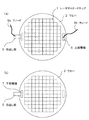
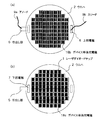
2 ウエハ
6 上部電極
7 下部電極
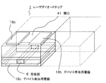
8 発振器
9a アノード
9b カソード
11 レーザ光発生/走査部
12 顕微鏡
13 レーザ光
18a、18b、18c チップ単体用電極
21 試料台
22 電圧供給部
23 電流変化検出/増幅部
24 温度制御部
25 熱媒体用パイプ
31 制御部
32 CRT
41 開口
Claims (10)
- 半導体レーザーダイオードチップが集積されたウエハに、該ウエハを構成する半導体のバンドギャップよりも小さく、かつ該ウエハの内部を透過するだけのエネルギーを有するレーザー光を走査しながら照射する照射工程と、
前記照射により前記ウエハの結晶欠陥に発生する熱起電力を、前記ウエハの上面と下面との間に現れる電圧または電流の変化により検出して表示する表示工程とを有する、
半導体レーザーダイオードチップウエハの検査方法。 - 前記電圧または電流の変化を検出する際に、前記ウエハの上面と下面との間に順バイアスまたは逆バイアスを印加する、請求項1に記載の検査方法。
- 半導体レーザーダイオードチップが集積されたウエハの上面と下面との間に一定の電流を流しながら、該ウエハに、該ウエハを構成する半導体のバンドギャップよりも小さく、かつ該ウエハの内部を透過するだけのエネルギーを有するレーザー光を走査しながら照射する工程と、
前記ウエハの結晶欠陥への前記照射により発生する前記電流の変化を検出して表示する工程とを有する、
半導体レーザーダイオードチップの検査方法。 - 前記表示は、前記レーザー光の照射位置と、該照射位置に対応する前記電圧または電流の変化との関係を画像に表示することにより行う、請求項1から3のいずれか1項に記載の検査方法。
- 前記ウエハの上面または下面のいずれか一つの面のみに、各レーザーダイオードチップのチップ単体用電極をあらかじめ設ける工程をさらに有し、前記チップ単体用電極の設けられていない面から前記照射を行う、請求項1から4のいずれか1項に記載の検査方法。
- 前記ウエハの上面または下面の少なくとも一つの面に、各レーザーダイオードチップの発振器に沿って開口を有するチップ単体用電極をあらかじめ設ける工程をさらに有し、前記開口から前記照射を行う、請求項1から4のいずれか1項に記載の検査方法。
- 半導体レーザーダイオードチップが集積されたウエハに、該ウエハを構成する半導体のバンドギャップよりも小さく、かつ該ウエハの内部を透過するだけのエネルギーを有するレーザー光を走査しながら照射する照射手段と、
前記照射により前記ウエハの結晶欠陥に発生する熱起電力を、前記ウエハの上面と下面との間に現れる電圧または電流の変化により検出して表示する表示手段とを有する、
半導体レーザーダイオードチップの検査装置。 - 前記電圧または電流の変化を検出する際に、前記ウエハの上面と下面との間に順バイアスまたは逆バイアスを印加する手段をさらに有する、請求項7に記載の検査装置。
- 半導体レーザーダイオードチップが集積されたウエハの上面と下面との間に一定の電流を流しながら、該ウエハに、該ウエハを構成する半導体のバンドギャップよりも小さく、かつ該ウエハの内部を透過するだけのエネルギーを有するレーザー光を走査しながら照射する照射手段と、
前記ウエハの結晶欠陥への前記照射により発生する前記電流の変化を検出して表示する表示手段とを有する、
半導体レーザーダイオードチップの検査装置。 - 前記表示手段は、前記レーザー光の照射位置と、該照射位置に対応する前記電圧または電流の変化をモニターに表示する手段である、請求項7から9のいずれか1項に記載の検査装置。
Priority Applications (7)
| Application Number | Priority Date | Filing Date | Title |
|---|---|---|---|
| JP2003274511A JP4136832B2 (ja) | 2003-07-15 | 2003-07-15 | 半導体レーザーダイオードチップの検査方法および検査装置 |
| TW093118671A TWI245356B (en) | 2003-07-15 | 2004-06-25 | Method for inspecting semiconductor device |
| US10/879,060 US7015051B2 (en) | 2003-07-15 | 2004-06-30 | Method for inspecting semiconductor device |
| DE602004020550T DE602004020550D1 (de) | 2003-07-15 | 2004-07-05 | Verfahren zur Untersuchung von Halbleitern |
| EP04015767A EP1498727B1 (en) | 2003-07-15 | 2004-07-05 | Method for inspecting semiconductor device |
| KR1020040054978A KR100633460B1 (ko) | 2003-07-15 | 2004-07-15 | 반도체 디바이스의 검사방법 |
| US11/287,458 US7332362B2 (en) | 2003-07-15 | 2005-11-28 | Method for inspecting semiconductor device |
Applications Claiming Priority (1)
| Application Number | Priority Date | Filing Date | Title |
|---|---|---|---|
| JP2003274511A JP4136832B2 (ja) | 2003-07-15 | 2003-07-15 | 半導体レーザーダイオードチップの検査方法および検査装置 |
Publications (3)
| Publication Number | Publication Date |
|---|---|
| JP2005039054A JP2005039054A (ja) | 2005-02-10 |
| JP2005039054A5 JP2005039054A5 (ja) | 2008-02-14 |
| JP4136832B2 true JP4136832B2 (ja) | 2008-08-20 |
Family
ID=33475552
Family Applications (1)
| Application Number | Title | Priority Date | Filing Date |
|---|---|---|---|
| JP2003274511A Expired - Fee Related JP4136832B2 (ja) | 2003-07-15 | 2003-07-15 | 半導体レーザーダイオードチップの検査方法および検査装置 |
Country Status (6)
| Country | Link |
|---|---|
| US (2) | US7015051B2 (ja) |
| EP (1) | EP1498727B1 (ja) |
| JP (1) | JP4136832B2 (ja) |
| KR (1) | KR100633460B1 (ja) |
| DE (1) | DE602004020550D1 (ja) |
| TW (1) | TWI245356B (ja) |
Families Citing this family (16)
| Publication number | Priority date | Publication date | Assignee | Title |
|---|---|---|---|---|
| US6898138B2 (en) * | 2002-08-29 | 2005-05-24 | Micron Technology, Inc. | Method of reducing variable retention characteristics in DRAM cells |
| JP4334927B2 (ja) * | 2003-06-27 | 2009-09-30 | キヤノン株式会社 | 半導体レーザーダイオードチップの検査方法および検査装置 |
| KR100688551B1 (ko) | 2005-06-07 | 2007-03-02 | 삼성전자주식회사 | 인터록기능을 구비한 반도체 웨이퍼 마킹장치 및 이를이용한 반도체 웨이퍼 마킹방법 |
| JP4363368B2 (ja) * | 2005-06-13 | 2009-11-11 | 住友電気工業株式会社 | 化合物半導体部材のダメージ評価方法、及び化合物半導体部材の製造方法 |
| JP2007081197A (ja) * | 2005-09-15 | 2007-03-29 | Sony Corp | 半導体レーザおよびその製造方法 |
| JP4694970B2 (ja) * | 2006-01-16 | 2011-06-08 | 三洋電機株式会社 | 半導体素子解析方法 |
| FR2902926B1 (fr) * | 2006-06-22 | 2008-10-24 | Commissariat Energie Atomique | Procede et dispositif de suivi d'un traitement thermique d'un substrat microtechnologique. |
| KR100827819B1 (ko) * | 2007-02-21 | 2008-05-07 | 전북대학교산학협력단 | 반도체 나노물질의 캐리어 타입 측정 시스템 및 반도체나노물질의 캐리어 타입의 측정 방법 |
| JP4374552B2 (ja) * | 2007-04-12 | 2009-12-02 | ソニー株式会社 | 基板の製造方法および基板製造システム、並びに表示装置の製造方法 |
| US7919973B2 (en) * | 2007-06-22 | 2011-04-05 | Microchip Technology Incorporated | Method and apparatus for monitoring via's in a semiconductor fab |
| JP2009008626A (ja) * | 2007-06-29 | 2009-01-15 | Nec Electronics Corp | 故障解析方法及び故障解析装置 |
| JP6137536B2 (ja) * | 2013-04-26 | 2017-05-31 | 日本電産リード株式会社 | 基板検査装置、及び基板検査方法 |
| DE102016008509A1 (de) * | 2016-07-13 | 2018-01-18 | Siltectra Gmbh | Laserkonditionierung von Festkörpern mit Vorwissen aus vorherigen Bearbeitungsschritten |
| CN110031188B (zh) * | 2019-03-29 | 2021-08-27 | 上海华岭集成电路技术股份有限公司 | 集成电路光学芯片光圈测试方法 |
| JP7092089B2 (ja) * | 2019-04-10 | 2022-06-28 | 株式会社Sumco | 半導体製品の導電型判別装置および導電型判別方法 |
| JP2022191643A (ja) * | 2021-06-16 | 2022-12-28 | 住友電気工業株式会社 | 面発光レーザの製造方法、面発光レーザの検査方法及び面発光レーザの検査装置 |
Family Cites Families (6)
| Publication number | Priority date | Publication date | Assignee | Title |
|---|---|---|---|---|
| US5422498A (en) | 1993-04-13 | 1995-06-06 | Nec Corporation | Apparatus for diagnosing interconnections of semiconductor integrated circuits |
| US5708371A (en) * | 1995-03-16 | 1998-01-13 | Mitsubishi Denki Kabushiki Kaisha | Scanning photoinduced current analyzer capable of detecting photoinduced current in nonbiased specimen |
| US5952837A (en) | 1995-07-18 | 1999-09-14 | Mitsubishi Denki Kabushiki Kaisha | Scanning photoinduced current analyzer capable of detecting photoinduced current in nonbiased specimen |
| DE19725679A1 (de) | 1997-06-18 | 1999-01-28 | Innomess Elektronik Gmbh | Verfahren und Vorrichtung zur Bestimmung der elektrischen Inhomogenität von Halbleitern |
| EP1580567A3 (en) | 1998-09-28 | 2006-11-29 | NEC Electronics Corporation | Device and method for nondestructive inspection on semiconductor device |
| JP4334927B2 (ja) * | 2003-06-27 | 2009-09-30 | キヤノン株式会社 | 半導体レーザーダイオードチップの検査方法および検査装置 |
-
2003
- 2003-07-15 JP JP2003274511A patent/JP4136832B2/ja not_active Expired - Fee Related
-
2004
- 2004-06-25 TW TW093118671A patent/TWI245356B/zh not_active IP Right Cessation
- 2004-06-30 US US10/879,060 patent/US7015051B2/en not_active Expired - Fee Related
- 2004-07-05 EP EP04015767A patent/EP1498727B1/en not_active Expired - Fee Related
- 2004-07-05 DE DE602004020550T patent/DE602004020550D1/de active Active
- 2004-07-15 KR KR1020040054978A patent/KR100633460B1/ko not_active IP Right Cessation
-
2005
- 2005-11-28 US US11/287,458 patent/US7332362B2/en not_active Expired - Fee Related
Also Published As
| Publication number | Publication date |
|---|---|
| US20050012923A1 (en) | 2005-01-20 |
| EP1498727B1 (en) | 2009-04-15 |
| TWI245356B (en) | 2005-12-11 |
| US7332362B2 (en) | 2008-02-19 |
| KR100633460B1 (ko) | 2006-10-16 |
| JP2005039054A (ja) | 2005-02-10 |
| KR20050008530A (ko) | 2005-01-21 |
| EP1498727A1 (en) | 2005-01-19 |
| DE602004020550D1 (de) | 2009-05-28 |
| TW200504910A (en) | 2005-02-01 |
| US20060079058A1 (en) | 2006-04-13 |
| US7015051B2 (en) | 2006-03-21 |
Similar Documents
| Publication | Publication Date | Title |
|---|---|---|
| US7332362B2 (en) | Method for inspecting semiconductor device | |
| JP4334927B2 (ja) | 半導体レーザーダイオードチップの検査方法および検査装置 | |
| JP5077872B2 (ja) | 太陽電池のフォトルミネセンスによる欠陥検査装置及び方法 | |
| JP6131250B2 (ja) | 光ルミネセンス画像化を使用する発光半導体デバイスの検査の方法および装置 | |
| JP5319593B2 (ja) | 太陽電池の検査方法および検査装置 | |
| US9222970B2 (en) | Fault position analysis method and fault position analysis device for semiconductor device | |
| WO2010116964A1 (ja) | 生体光計測装置及び光ファイバの断線判定方法 | |
| JP2007042492A (ja) | 有機elリペア方法とリペア装置 | |
| JP6317321B2 (ja) | 電界集中位置観察装置および電界集中位置観察方法 | |
| US20210239757A1 (en) | System and method for identifying latent reliability defects in semiconductor devices | |
| JP2010197051A (ja) | 故障解析装置 | |
| JP2005294449A (ja) | 半導体装置の検査方法および検査装置 | |
| KR102170357B1 (ko) | 비파괴 결함 검출방법 | |
| JP7376369B2 (ja) | 半導体素子の検査装置 | |
| JP2019039939A (ja) | マーキング装置 | |
| JPH09266238A (ja) | 電子回路の欠陥検査装置 | |
| JP2016045104A (ja) | マーキング装置及びマーキング方法 | |
| JP2008046101A (ja) | 半導体デバイスの欠陥評価方法及び欠陥評価装置 | |
| JP2005083951A (ja) | エミッション・マイクロスコープ法による有機el素子の検査法 | |
| JP2007078379A (ja) | フラットパネルディスプレイ用パネル回路基板の欠陥検査方法、当該パネル回路基板の製造方法及び欠陥検査装置 | |
| JP2009170757A (ja) | 光半導体素子の検査方法 | |
| JPH05175293A (ja) | 半導体チップの解析方法 |
Legal Events
| Date | Code | Title | Description |
|---|---|---|---|
| A621 | Written request for application examination |
Free format text: JAPANESE INTERMEDIATE CODE: A621 Effective date: 20060711 |
|
| A521 | Written amendment |
Free format text: JAPANESE INTERMEDIATE CODE: A523 Effective date: 20071225 |
|
| A977 | Report on retrieval |
Free format text: JAPANESE INTERMEDIATE CODE: A971007 Effective date: 20080215 |
|
| A131 | Notification of reasons for refusal |
Free format text: JAPANESE INTERMEDIATE CODE: A131 Effective date: 20080220 |
|
| RD03 | Notification of appointment of power of attorney |
Free format text: JAPANESE INTERMEDIATE CODE: A7423 Effective date: 20080328 |
|
| A521 | Written amendment |
Free format text: JAPANESE INTERMEDIATE CODE: A523 Effective date: 20080417 |
|
| TRDD | Decision of grant or rejection written | ||
| A01 | Written decision to grant a patent or to grant a registration (utility model) |
Free format text: JAPANESE INTERMEDIATE CODE: A01 Effective date: 20080514 |
|
| A01 | Written decision to grant a patent or to grant a registration (utility model) |
Free format text: JAPANESE INTERMEDIATE CODE: A01 |
|
| A61 | First payment of annual fees (during grant procedure) |
Free format text: JAPANESE INTERMEDIATE CODE: A61 Effective date: 20080603 |
|
| R150 | Certificate of patent or registration of utility model |
Free format text: JAPANESE INTERMEDIATE CODE: R150 |
|
| FPAY | Renewal fee payment (event date is renewal date of database) |
Free format text: PAYMENT UNTIL: 20110613 Year of fee payment: 3 |
|
| FPAY | Renewal fee payment (event date is renewal date of database) |
Free format text: PAYMENT UNTIL: 20120613 Year of fee payment: 4 |
|
| FPAY | Renewal fee payment (event date is renewal date of database) |
Free format text: PAYMENT UNTIL: 20120613 Year of fee payment: 4 |
|
| FPAY | Renewal fee payment (event date is renewal date of database) |
Free format text: PAYMENT UNTIL: 20130613 Year of fee payment: 5 |
|
| LAPS | Cancellation because of no payment of annual fees |