JP2019108201A - クレーン立組方法 - Google Patents
クレーン立組方法 Download PDFInfo
- Publication number
- JP2019108201A JP2019108201A JP2017242108A JP2017242108A JP2019108201A JP 2019108201 A JP2019108201 A JP 2019108201A JP 2017242108 A JP2017242108 A JP 2017242108A JP 2017242108 A JP2017242108 A JP 2017242108A JP 2019108201 A JP2019108201 A JP 2019108201A
- Authority
- JP
- Japan
- Prior art keywords
- jib
- partial
- tip
- connector
- crane
- Prior art date
- Legal status (The legal status is an assumption and is not a legal conclusion. Google has not performed a legal analysis and makes no representation as to the accuracy of the status listed.)
- Granted
Links
Images


Classifications
-
- B—PERFORMING OPERATIONS; TRANSPORTING
- B66—HOISTING; LIFTING; HAULING
- B66C—CRANES; LOAD-ENGAGING ELEMENTS OR DEVICES FOR CRANES, CAPSTANS, WINCHES, OR TACKLES
- B66C23/00—Cranes comprising essentially a beam, boom, or triangular structure acting as a cantilever and mounted for translatory of swinging movements in vertical or horizontal planes or a combination of such movements, e.g. jib-cranes, derricks, tower cranes
- B66C23/18—Cranes comprising essentially a beam, boom, or triangular structure acting as a cantilever and mounted for translatory of swinging movements in vertical or horizontal planes or a combination of such movements, e.g. jib-cranes, derricks, tower cranes specially adapted for use in particular purposes
- B66C23/26—Cranes comprising essentially a beam, boom, or triangular structure acting as a cantilever and mounted for translatory of swinging movements in vertical or horizontal planes or a combination of such movements, e.g. jib-cranes, derricks, tower cranes specially adapted for use in particular purposes for use on building sites; constructed, e.g. with separable parts, to facilitate rapid assembly or dismantling, for operation at successively higher levels, for transport by road or rail
- B66C23/34—Self-erecting cranes, i.e. with hoisting gear adapted for crane erection purposes
-
- B—PERFORMING OPERATIONS; TRANSPORTING
- B66—HOISTING; LIFTING; HAULING
- B66C—CRANES; LOAD-ENGAGING ELEMENTS OR DEVICES FOR CRANES, CAPSTANS, WINCHES, OR TACKLES
- B66C23/00—Cranes comprising essentially a beam, boom, or triangular structure acting as a cantilever and mounted for translatory of swinging movements in vertical or horizontal planes or a combination of such movements, e.g. jib-cranes, derricks, tower cranes
- B66C23/18—Cranes comprising essentially a beam, boom, or triangular structure acting as a cantilever and mounted for translatory of swinging movements in vertical or horizontal planes or a combination of such movements, e.g. jib-cranes, derricks, tower cranes specially adapted for use in particular purposes
- B66C23/36—Cranes comprising essentially a beam, boom, or triangular structure acting as a cantilever and mounted for translatory of swinging movements in vertical or horizontal planes or a combination of such movements, e.g. jib-cranes, derricks, tower cranes specially adapted for use in particular purposes mounted on road or rail vehicles; Manually-movable jib-cranes for use in workshops; Floating cranes
- B66C23/42—Cranes comprising essentially a beam, boom, or triangular structure acting as a cantilever and mounted for translatory of swinging movements in vertical or horizontal planes or a combination of such movements, e.g. jib-cranes, derricks, tower cranes specially adapted for use in particular purposes mounted on road or rail vehicles; Manually-movable jib-cranes for use in workshops; Floating cranes with jibs of adjustable configuration, e.g. foldable
-
- B—PERFORMING OPERATIONS; TRANSPORTING
- B66—HOISTING; LIFTING; HAULING
- B66C—CRANES; LOAD-ENGAGING ELEMENTS OR DEVICES FOR CRANES, CAPSTANS, WINCHES, OR TACKLES
- B66C23/00—Cranes comprising essentially a beam, boom, or triangular structure acting as a cantilever and mounted for translatory of swinging movements in vertical or horizontal planes or a combination of such movements, e.g. jib-cranes, derricks, tower cranes
- B66C23/62—Constructional features or details
- B66C23/64—Jibs
- B66C23/70—Jibs constructed of sections adapted to be assembled to form jibs or various lengths
- B66C23/701—Jibs constructed of sections adapted to be assembled to form jibs or various lengths telescopic
- B66C23/702—Jibs constructed of sections adapted to be assembled to form jibs or various lengths telescopic with a jib extension boom
-
- B—PERFORMING OPERATIONS; TRANSPORTING
- B66—HOISTING; LIFTING; HAULING
- B66C—CRANES; LOAD-ENGAGING ELEMENTS OR DEVICES FOR CRANES, CAPSTANS, WINCHES, OR TACKLES
- B66C23/00—Cranes comprising essentially a beam, boom, or triangular structure acting as a cantilever and mounted for translatory of swinging movements in vertical or horizontal planes or a combination of such movements, e.g. jib-cranes, derricks, tower cranes
- B66C23/62—Constructional features or details
- B66C23/82—Luffing gear
Abstract
Description
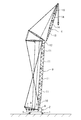
図1に本発明の一実施形態に係るクレーン立組方法よって組み立てられるクレーンの構成を示す。
下部走行体1は、走行装置として一対のクローラー(履帯)5を有する。
上部旋回体2は、操縦者用キャビン6、ブーム3を起伏させるブーム起伏ウインチ7、ジブ4を起伏させるジブ起伏ウインチ8、ジブ4の先端から垂下され、吊り荷を吊り上げるロープを巻上げる巻上げウインチ9等が設けられている。
ブーム3は、下部ブーム10、複数の中間ブーム11及びタワーキャップ12を長手方向に順番に接続して形成され、下部ブーム10が上部旋回体2に取り付けられ、タワーキャップ12にジブ4が連結される。下部ブーム10及び複数の中間ブーム11は、4本の主桁(柱)と、隣接する主桁間を接続する複数の補桁(ラチス)とを有し、概略四角筒状の骨組み構造体とされたラチス構造を有する。
ジブ4は、複数のパーシャルジブ(下部ジブ13、複数の中間ジブ14及び上部ジブ15)を長手方向に接続して形成され、下部ジブ13がブーム3の先端に連結される。これらのパーシャルジブ13,14,15は、4本の主桁(柱)と、隣接する主桁間を接続する複数の補桁(ラチス)とを有し、概略四角筒状又は四角錐状の骨組み構造体とされたラチス構造を有する。
背側コネクタ16及び腹側コネクタ17は、パーシャルジブ13,14,15の主桁の端部から長手方向に突出するよう設けられる1又は複数の板状体とすることができる。互いに接続される背側コネクタ16同士及び腹側コネクタ17同士は、水平方向に隣接して配置されるよう位置をずらして配設される。また、互いに接続される一対の背側コネクタ16及び一対の腹側コネクタ17は、それぞれ少なくとも一方が水平方向に間隔を空けて突設される複数の板状体から形成され、この複数の板状体の間に対をなす背側コネクタ16又は腹側コネクタ17が嵌合するよう構成されることが好ましい。
車輪19は、腹側コネクタ17の固定ピン18が挿入される穴に挿入される軸19aを有し、この軸19aを中心に回転する。このため、軸19aは、例えば軸受け、ブッシング等を介して設けられることが好ましい。また、軸19aは、腹側コネクタ17を貫通して突出する先端部に例えばピン、止め輪等の抜け止めを装着可能に構成されることが好ましい。
本発明の一実施形態に係るクレーン立組方法は、ブーム3を上部旋回体2に組み付けた後、ブーム3の先端にパーシャルジブ13,14,15を1本ずつ順番に接続することによってジブ4を組み立てる。
ブーム組み付け工程は、一般的な平組の場合と同様に、ブーム3を地面上に倒伏した状態で組み立てて上部旋回体2に取り付ける。また、上部旋回体2に下部ブーム10を取り付けた後、複数の中間ブーム11及びタワーキャップ12を順に取り付けてもよい。
下部ジブ接続工程は、組み立て用クレーンを用いて、ブーム3の先端に下部ジブ13を取り付ける。この下部ジブ接続工程は、下部ジブ13を水平に吊り上げて行うことができるよう、ブーム3の先端を僅かに持ち上げた状態で行うことが好ましい。
中間ジブ接続工程は、下部ジブ13を1本目として数える自然数nを用いて表すと、ブーム3にn本のパーシャルジブ(下部ジブ13又は下部ジブ13及び1又は複数の中間ジブ14)が接続された状態で、n本目のパーシャルジブ(下部ジブ13又は下部ジブ13に接続されている中間ジブ14のうち最先端の中間ジブ14)の先端にn+1本目のパーシャルジブ(さらなる中間ジブ14)を接続する工程である。
載置工程では、先ず、図5に示すように、n本目のパーシャルジブ13,14の先端部を組み立て用クレーンで吊り上げながら、ブーム3を僅かに起こしてブーム3の先端が地面から離間した状態とする。
背側コネクタ接続工程では、図7に示すように、組み立て用クレーンでn+1本目のパーシャルジブ14を吊り上げて、n本目のパーシャルジブ13,14の背側コネクタ16にn+1本目のパーシャルジブ14の背側コネクタ16を位置合わせする。この状態で、両者の背側コネクタ16に固定ピン18を挿入することによって、n本目のパーシャルジブ13,14の背側コネクタ16にn+1本目のパーシャルジブ14の背側コネクタ16を接続する。
車輪取付工程では、図8に示すように、組み立て用クレーンにより吊り上げた状態のn+1本目のパーシャルジブ14の先端側の腹側コネクタ17に車輪19を取り付ける。そして、組み立て用クレーンのロープを送出して、図9に示すように、車輪19を接地させる。つまり、車輪19によって+1本目のパーシャルジブ14の先端側の重量を支える。
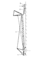
腹側コネクタ接続工程では、図10に示すように、組み立て用クレーンによって、n本目のパーシャルジブ13,14とn+1本目のパーシャルジブ14との接続部の近傍を吊り上げることにより、n本目のパーシャルジブ13,14をブーム3の先端を中心に起立方向に揺動させる。これに伴って、n+1本目のパーシャルジブ14の基端側の背側コネクタ16が持ち上げられるので、n+1本目のパーシャルジブ14は倒伏方向に揺動する。これにより、背側コネクタ16に挿入された固定ピン18を中心として、n本目のパーシャルジブ14の先端側の腹側コネクタ17とn+1本目のパーシャルジブ14の基端側の腹側コネクタ17とが重なり合うよう移動する。重なり合ったn本目のパーシャルジブ14の先端側の腹側コネクタ17とn+1本目のパーシャルジブ14の基端側の腹側コネクタ17との両方を貫通するよう固定ピン18を挿入することで、n本目のパーシャルジブ13,14の先端に、n+1本目のパーシャルジブ14が固定される。
先端移動工程では、図11に示すように、ブーム3を起こすことにより、ブーム3の先端に連結されている複数のパーシャルジブ13,14の接続体の基端部を持ち上げてn+1本目のパーシャルジブ14の先端部を引き寄せる。
上部ジブ接続工程は、ブーム3の先端を地面から離間した状態で、最先端のパーシャルジブ14の先端を地面に配置した台座上に載置する工程<載置工程>と、上部ジブ15を吊り上げた状態で、最先端の中間ジブ14の先端側の背側コネクタ16に上部ジブ15の基端側の背側コネクタ16を接続する工程<背側コネクタ接続工程>と、上部ジブ15の先端部に車輪20を取り付ける工程<車輪取付工程>と、最先端の中間ジブ14の先端側の腹側コネクタ17と上部ジブ15の基端側の腹側コネクタ17とを接続する工程<腹側コネクタ接続工程>とを有する。
当該クレーン立組方法は、上述のようにパーシャルジブ13,14,15を1本ずつブーム3に接続し、ブーム3に接続されたパーシャルジブの合計長さに応じてブーム3を起こすことによって、必要とされる作業スペースの水平方向の長さを小さくすることができる。つまり、当該クレーン組み立て方法は、ブーム3及びジブ4の合計長さよりも長さが小さい場所でもクレーンを組み立てることができる。
上記実施形態は、本発明の構成を限定するものではない。従って、上記実施形態は、本明細書の記載及び技術常識に基づいて上記実施形態各部の構成要素の省略、置換又は追加が可能であり、それらは全て本発明の範囲に属するものと解釈されるべきである。
2 上部旋回体
3 ブーム
4 ジブ
5 クローラー
6 操縦者用キャビン
7 ブーム起伏ウインチ
8 ジブ起伏ウインチ
9 巻上げウインチ
10 下部ブーム
11 中間ブーム
12 タワーキャップ
13 下部ジブ(パーシャルジブ)
14 中間ジブ(パーシャルジブ)
15 上部ジブ(パーシャルジブ)
16 背側コネクタ
17 腹側コネクタ
18 固定ピン
19 車輪
19a 軸
20 車輪
S 台座
Claims (3)
- 水平回転可能な旋回体と、
上記旋回体上に起伏可能に配設されるブームと、
上記ブームの先端に起伏可能に連結されるジブと
を備え、
上記ジブが、複数のパーシャルジブを長手方向に接続して形成され、
上記複数のパーシャルジブが、互いに接続される側の端部の背側及び腹側に突設され、起伏の軸に固定ピンが挿入されることにより互いに接続される背側コネクタ及び腹側コネクタを有するクレーンを組み立てる方法であって、
自然数nを用いて表すと、上記ブームにn本の上記パーシャルジブが接続された状態で、n本目の上記パーシャルジブの先端にn+1本目の上記パーシャルジブを接続する工程を備え、
上記n+1本目の上記パーシャルジブを接続する工程が、
上記ブームの先端を地面から離間した状態で、上記ブームに連結されたn本目の上記パーシャルジブの先端を地面に又は地面から浮かせて載置する工程と、
n+1本目の上記パーシャルジブを吊り上げた状態で、n本目の上記パーシャルジブの先端側の背側コネクタにn+1本目の上記パーシャルジブの基端側の背側コネクタを接続する工程と、
n+1本目の上記パーシャルジブの先端側の腹側コネクタに車輪を取り付ける工程と、
n本目の上記パーシャルジブ及びn+1本目の上記パーシャルジブ間の接続部近傍を吊り上げることにより、n本目の上記パーシャルジブの腹側コネクタとn+1本目の上記パーシャルジブの基端側の上記腹側コネクタとを接続する工程と
を有することを特徴とするクレーン立組方法。 - 上記ブームを起こすことにより、上記n+1本目の上記パーシャルジブの基端側の背側コネクタを接続する工程でn本目の上記パーシャルジブの先端が載置されていた位置の近傍に、上記n+1本目の上記パーシャルジブの先端を移動させる工程をさらに有する請求項1に記載のクレーン立組方法。
- 上記車輪が上記腹側コネクタの上記固定ピンが挿入される穴に挿入される軸を中心に回転する請求項1又は請求項2に記載のクレーン立組方法。
Priority Applications (3)
| Application Number | Priority Date | Filing Date | Title |
|---|---|---|---|
| JP2017242108A JP6638718B2 (ja) | 2017-12-18 | 2017-12-18 | クレーン立組方法 |
| EP18211224.3A EP3498655B1 (en) | 2017-12-18 | 2018-12-10 | Crane assembling method |
| US16/214,579 US10526176B2 (en) | 2017-12-18 | 2018-12-10 | Crane assembling method |
Applications Claiming Priority (1)
| Application Number | Priority Date | Filing Date | Title |
|---|---|---|---|
| JP2017242108A JP6638718B2 (ja) | 2017-12-18 | 2017-12-18 | クレーン立組方法 |
Publications (2)
| Publication Number | Publication Date |
|---|---|
| JP2019108201A true JP2019108201A (ja) | 2019-07-04 |
| JP6638718B2 JP6638718B2 (ja) | 2020-01-29 |
Family
ID=64664095
Family Applications (1)
| Application Number | Title | Priority Date | Filing Date |
|---|---|---|---|
| JP2017242108A Active JP6638718B2 (ja) | 2017-12-18 | 2017-12-18 | クレーン立組方法 |
Country Status (3)
| Country | Link |
|---|---|
| US (1) | US10526176B2 (ja) |
| EP (1) | EP3498655B1 (ja) |
| JP (1) | JP6638718B2 (ja) |
Cited By (1)
| Publication number | Priority date | Publication date | Assignee | Title |
|---|---|---|---|---|
| CN112830400A (zh) * | 2021-02-01 | 2021-05-25 | 浙江三一装备有限公司 | 履带起重机及起重机运输方法 |
Families Citing this family (3)
| Publication number | Priority date | Publication date | Assignee | Title |
|---|---|---|---|---|
| JP7126981B2 (ja) * | 2019-03-29 | 2022-08-29 | 住友重機械建機クレーン株式会社 | クレーン |
| CN111422763B (zh) * | 2019-12-13 | 2021-11-26 | 武汉检安石化工程有限公司 | 组杆区域存在障碍物情况下的吊臂组装方法 |
| DE102021106745A1 (de) * | 2021-03-19 | 2022-09-22 | Liebherr-Werk Nenzing Gmbh | Hebezeug mit einer Vorrichtung zum Unterstützen oder vollautomatischen Durchführen eines Aufricht- und/oder Ablegevorgangs eines Auslegersystems sowie entsprechendes Verfahren |
Citations (8)
| Publication number | Priority date | Publication date | Assignee | Title |
|---|---|---|---|---|
| JPS60122791U (ja) * | 1984-01-27 | 1985-08-19 | 日立建機株式会社 | 分割式クレ−ンブ−ムを備える移動式クレ−ン |
| JPH10194677A (ja) * | 1997-01-14 | 1998-07-28 | Tadano Ltd | ラフィングジブ付きブームクレーンにおけるラフィングジブ支持装置 |
| JPH10316366A (ja) * | 1997-05-21 | 1998-12-02 | Tadano Ltd | ラフィングジブ組み立て方法 |
| JP2012116607A (ja) * | 2010-11-30 | 2012-06-21 | Hitachi Sumitomo Heavy Industries Construction Crane Co Ltd | 移動式クレーンおよび移動式クレーンの組立方法 |
| JP2014065573A (ja) * | 2012-09-26 | 2014-04-17 | Kobelco Cranes Co Ltd | 下部ジブ |
| WO2015069096A1 (en) * | 2013-11-08 | 2015-05-14 | Itrec B.V. | Crane boom segment for assembly of a crane boom, method for assembling a crane boom |
| JP2016040204A (ja) * | 2007-11-29 | 2016-03-24 | マニタウォック クレイン カンパニーズ, エルエルシーManitowoc Crane Companies, Llc | クレーンブームセグメント用の接続システム |
| JP2017137164A (ja) * | 2016-02-03 | 2017-08-10 | コベルコクレーン株式会社 | クレーンのジブ取付方法 |
Family Cites Families (17)
| Publication number | Priority date | Publication date | Assignee | Title |
|---|---|---|---|---|
| US3083837A (en) * | 1961-01-31 | 1963-04-02 | Thew Shovel Co | Crane |
| US3263383A (en) * | 1962-07-16 | 1966-08-02 | Edward T Foster | Safety carriage for crane booms |
| US3306470A (en) * | 1965-01-25 | 1967-02-28 | Robert A Green | Folding boom for mobile cranes |
| US3794184A (en) * | 1973-01-15 | 1974-02-26 | Joyce Burroughs Torregrossa | Crane |
| US3945333A (en) | 1974-12-20 | 1976-03-23 | Harnischfeger Corporation | Means for storing and connecting jib for telescopic boom of mobile crane |
| JP3980123B2 (ja) * | 1996-04-26 | 2007-09-26 | マニタウォック クレイン カンパニーズ インコーポレイテッド | ブームホイストシリンダクレーン |
| US6481202B1 (en) * | 1997-04-16 | 2002-11-19 | Manitowoc Crane Companies, Inc. | Hydraulic system for boom hoist cylinder crane |
| CN1767998A (zh) * | 2003-04-02 | 2006-05-03 | 德雷克斯-德马格股份有限公司 | 桁架吊臂起重机的两件式主吊臂及其架设方法 |
| JP5046599B2 (ja) | 2006-09-27 | 2012-10-10 | 株式会社タダノ | クレーンのラフィングジブ装置 |
| DE102007056289B4 (de) * | 2007-10-29 | 2009-06-04 | Liebherr-Werk Ehingen Gmbh | Verfahren zum Aufrichten eines Kranauslegers |
| DE102007051539C5 (de) * | 2007-10-29 | 2018-04-12 | Liebherr-Werk Ehingen Gmbh | Verfahren zum Aufrichten eines Kranauslegers |
| DE102009010452A1 (de) * | 2009-02-26 | 2010-09-02 | Terex-Demag Gmbh | Verfahren und Einrichtung zum An-und Abbau einer Zusatzeinrichtung am Hauptausleger eines Mobilkrans |
| US8684197B2 (en) * | 2009-05-01 | 2014-04-01 | Manitowoc Crane Companies, Llc | Crane with boom raising assist structure |
| US9206021B2 (en) * | 2012-09-26 | 2015-12-08 | Kobelco Cranes Co., Ltd. | Crane and crane assembling method |
| JP6004537B2 (ja) * | 2013-03-18 | 2016-10-12 | コベルコ建機株式会社 | ジブ |
| DE102014012422B4 (de) * | 2014-08-20 | 2023-02-09 | Liebherr-Werk Ehingen Gmbh | Automatisches Aufrichten eines Krans |
| CN107567426A (zh) * | 2015-02-18 | 2018-01-09 | 苏科夫有限责任公司 | 组装起重机的方法和操作起重机的方法 |
-
2017
- 2017-12-18 JP JP2017242108A patent/JP6638718B2/ja active Active
-
2018
- 2018-12-10 EP EP18211224.3A patent/EP3498655B1/en active Active
- 2018-12-10 US US16/214,579 patent/US10526176B2/en active Active
Patent Citations (8)
| Publication number | Priority date | Publication date | Assignee | Title |
|---|---|---|---|---|
| JPS60122791U (ja) * | 1984-01-27 | 1985-08-19 | 日立建機株式会社 | 分割式クレ−ンブ−ムを備える移動式クレ−ン |
| JPH10194677A (ja) * | 1997-01-14 | 1998-07-28 | Tadano Ltd | ラフィングジブ付きブームクレーンにおけるラフィングジブ支持装置 |
| JPH10316366A (ja) * | 1997-05-21 | 1998-12-02 | Tadano Ltd | ラフィングジブ組み立て方法 |
| JP2016040204A (ja) * | 2007-11-29 | 2016-03-24 | マニタウォック クレイン カンパニーズ, エルエルシーManitowoc Crane Companies, Llc | クレーンブームセグメント用の接続システム |
| JP2012116607A (ja) * | 2010-11-30 | 2012-06-21 | Hitachi Sumitomo Heavy Industries Construction Crane Co Ltd | 移動式クレーンおよび移動式クレーンの組立方法 |
| JP2014065573A (ja) * | 2012-09-26 | 2014-04-17 | Kobelco Cranes Co Ltd | 下部ジブ |
| WO2015069096A1 (en) * | 2013-11-08 | 2015-05-14 | Itrec B.V. | Crane boom segment for assembly of a crane boom, method for assembling a crane boom |
| JP2017137164A (ja) * | 2016-02-03 | 2017-08-10 | コベルコクレーン株式会社 | クレーンのジブ取付方法 |
Cited By (1)
| Publication number | Priority date | Publication date | Assignee | Title |
|---|---|---|---|---|
| CN112830400A (zh) * | 2021-02-01 | 2021-05-25 | 浙江三一装备有限公司 | 履带起重机及起重机运输方法 |
Also Published As
| Publication number | Publication date |
|---|---|
| EP3498655B1 (en) | 2020-06-24 |
| US20190185297A1 (en) | 2019-06-20 |
| US10526176B2 (en) | 2020-01-07 |
| EP3498655A1 (en) | 2019-06-19 |
| JP6638718B2 (ja) | 2020-01-29 |
Similar Documents
| Publication | Publication Date | Title |
|---|---|---|
| JP2019108201A (ja) | クレーン立組方法 | |
| EP1735233B1 (en) | Mobile crane system comprising a mobile crane and an auxiliary device for assembly of a bracing device | |
| JP4857880B2 (ja) | 移動式クレーンのブームの取り付け方法及びブーム取り付け用具 | |
| JP2014144853A (ja) | ブーム及び起伏部材 | |
| JP2019069838A (ja) | クレーン、ジブ組立て方法 | |
| JP2016222359A (ja) | クレーン | |
| US10640341B2 (en) | Method for raising raisable and lowerable member, and crane | |
| JP6645222B2 (ja) | クレーンのジブ取付方法 | |
| JP2010018355A (ja) | ブーム起伏装置 | |
| JP5540875B2 (ja) | ホイールクレーンのフック部保持具及びフック装置 | |
| JP6683086B2 (ja) | 移動式クレーンの組立方法 | |
| JP6984395B2 (ja) | クレーン及びクレーン組み立て方法 | |
| JP6202080B2 (ja) | クレーン | |
| JP2017137171A (ja) | クレーン、およびクレーンのブーム取付方法 | |
| JP7416034B2 (ja) | クレーンの組立方法 | |
| JP6658020B2 (ja) | クレーン、およびクレーンの組立方法 | |
| JP6246707B2 (ja) | ブーム取付装置およびクレーン | |
| JP2017145094A (ja) | クレーンの車輪装置 | |
| JP7234811B2 (ja) | クレーンのストラット、クレーンのストラットの折り畳み方法、および、クレーンのストラットの組立方法 | |
| JP7163607B2 (ja) | クレーンおよびクレーンの組立方法 | |
| JP6579172B2 (ja) | クレーンおよびクレーンのストラット引き起こし方法 | |
| JP6720990B2 (ja) | テンションメンバ支持装置、およびテンションメンバ分解方法 | |
| JP6776740B2 (ja) | 作業機械、及び、作業機械における本体に対するウィンチの着脱方法 | |
| JP2018048015A (ja) | 移動式クレーンの組立方法 | |
| JP6642543B2 (ja) | 吊り具 |
Legal Events
| Date | Code | Title | Description |
|---|---|---|---|
| A621 | Written request for application examination |
Free format text: JAPANESE INTERMEDIATE CODE: A621 Effective date: 20181121 |
|
| A977 | Report on retrieval |
Free format text: JAPANESE INTERMEDIATE CODE: A971007 Effective date: 20190906 |
|
| A131 | Notification of reasons for refusal |
Free format text: JAPANESE INTERMEDIATE CODE: A131 Effective date: 20190917 |
|
| A521 | Request for written amendment filed |
Free format text: JAPANESE INTERMEDIATE CODE: A523 Effective date: 20191113 |
|
| TRDD | Decision of grant or rejection written | ||
| A01 | Written decision to grant a patent or to grant a registration (utility model) |
Free format text: JAPANESE INTERMEDIATE CODE: A01 Effective date: 20191126 |
|
| A61 | First payment of annual fees (during grant procedure) |
Free format text: JAPANESE INTERMEDIATE CODE: A61 Effective date: 20191209 |
|
| R150 | Certificate of patent or registration of utility model |
Ref document number: 6638718 Country of ref document: JP Free format text: JAPANESE INTERMEDIATE CODE: R150 |