JP2019108201A - Vertically assembling method of crane - Google Patents
Vertically assembling method of crane Download PDFInfo
- Publication number
- JP2019108201A JP2019108201A JP2017242108A JP2017242108A JP2019108201A JP 2019108201 A JP2019108201 A JP 2019108201A JP 2017242108 A JP2017242108 A JP 2017242108A JP 2017242108 A JP2017242108 A JP 2017242108A JP 2019108201 A JP2019108201 A JP 2019108201A
- Authority
- JP
- Japan
- Prior art keywords
- jib
- partial
- tip
- connector
- crane
- Prior art date
- Legal status (The legal status is an assumption and is not a legal conclusion. Google has not performed a legal analysis and makes no representation as to the accuracy of the status listed.)
- Granted
Links
Images


Classifications
-
- B—PERFORMING OPERATIONS; TRANSPORTING
- B66—HOISTING; LIFTING; HAULING
- B66C—CRANES; LOAD-ENGAGING ELEMENTS OR DEVICES FOR CRANES, CAPSTANS, WINCHES, OR TACKLES
- B66C23/00—Cranes comprising essentially a beam, boom, or triangular structure acting as a cantilever and mounted for translatory of swinging movements in vertical or horizontal planes or a combination of such movements, e.g. jib-cranes, derricks, tower cranes
- B66C23/18—Cranes comprising essentially a beam, boom, or triangular structure acting as a cantilever and mounted for translatory of swinging movements in vertical or horizontal planes or a combination of such movements, e.g. jib-cranes, derricks, tower cranes specially adapted for use in particular purposes
- B66C23/26—Cranes comprising essentially a beam, boom, or triangular structure acting as a cantilever and mounted for translatory of swinging movements in vertical or horizontal planes or a combination of such movements, e.g. jib-cranes, derricks, tower cranes specially adapted for use in particular purposes for use on building sites; constructed, e.g. with separable parts, to facilitate rapid assembly or dismantling, for operation at successively higher levels, for transport by road or rail
- B66C23/34—Self-erecting cranes, i.e. with hoisting gear adapted for crane erection purposes
-
- B—PERFORMING OPERATIONS; TRANSPORTING
- B66—HOISTING; LIFTING; HAULING
- B66C—CRANES; LOAD-ENGAGING ELEMENTS OR DEVICES FOR CRANES, CAPSTANS, WINCHES, OR TACKLES
- B66C23/00—Cranes comprising essentially a beam, boom, or triangular structure acting as a cantilever and mounted for translatory of swinging movements in vertical or horizontal planes or a combination of such movements, e.g. jib-cranes, derricks, tower cranes
- B66C23/18—Cranes comprising essentially a beam, boom, or triangular structure acting as a cantilever and mounted for translatory of swinging movements in vertical or horizontal planes or a combination of such movements, e.g. jib-cranes, derricks, tower cranes specially adapted for use in particular purposes
- B66C23/36—Cranes comprising essentially a beam, boom, or triangular structure acting as a cantilever and mounted for translatory of swinging movements in vertical or horizontal planes or a combination of such movements, e.g. jib-cranes, derricks, tower cranes specially adapted for use in particular purposes mounted on road or rail vehicles; Manually-movable jib-cranes for use in workshops; Floating cranes
- B66C23/42—Cranes comprising essentially a beam, boom, or triangular structure acting as a cantilever and mounted for translatory of swinging movements in vertical or horizontal planes or a combination of such movements, e.g. jib-cranes, derricks, tower cranes specially adapted for use in particular purposes mounted on road or rail vehicles; Manually-movable jib-cranes for use in workshops; Floating cranes with jibs of adjustable configuration, e.g. foldable
-
- B—PERFORMING OPERATIONS; TRANSPORTING
- B66—HOISTING; LIFTING; HAULING
- B66C—CRANES; LOAD-ENGAGING ELEMENTS OR DEVICES FOR CRANES, CAPSTANS, WINCHES, OR TACKLES
- B66C23/00—Cranes comprising essentially a beam, boom, or triangular structure acting as a cantilever and mounted for translatory of swinging movements in vertical or horizontal planes or a combination of such movements, e.g. jib-cranes, derricks, tower cranes
- B66C23/62—Constructional features or details
- B66C23/64—Jibs
- B66C23/70—Jibs constructed of sections adapted to be assembled to form jibs or various lengths
- B66C23/701—Jibs constructed of sections adapted to be assembled to form jibs or various lengths telescopic
- B66C23/702—Jibs constructed of sections adapted to be assembled to form jibs or various lengths telescopic with a jib extension boom
-
- B—PERFORMING OPERATIONS; TRANSPORTING
- B66—HOISTING; LIFTING; HAULING
- B66C—CRANES; LOAD-ENGAGING ELEMENTS OR DEVICES FOR CRANES, CAPSTANS, WINCHES, OR TACKLES
- B66C23/00—Cranes comprising essentially a beam, boom, or triangular structure acting as a cantilever and mounted for translatory of swinging movements in vertical or horizontal planes or a combination of such movements, e.g. jib-cranes, derricks, tower cranes
- B66C23/62—Constructional features or details
- B66C23/82—Luffing gear
Abstract
Description
本発明はクレーン立組方法に関する。 The present invention relates to a crane erecting method.
ブームの先端にジブを備えるラッフィングジブクレーンやタワークレーン等のクレーンが知られている。ジブを備える大型のクレーンは、ジブが複数の部分(パーシャルジブ)に分割可能に構成され、クレーンを使用する現場においてジブが組み立てられる。 There are known cranes such as luffing jib cranes and tower cranes provided with a jib at the tip of a boom. In a large crane equipped with a jib, the jib can be divided into a plurality of parts (partial jibs), and the jib is assembled at the site where the crane is used.
一般に、大型のクレーンは、ブーム及びジブを一直線に延ばして地面に倒伏した状態で組み立てられる(いわゆる「平組」)。しかしながら、このような平組は、ブーム及びジブを水平に延ばすことができるような水平方向に長いスペースを必要とする。このため、大型のクレーンを使用する場合には、平組することができるような十分なスペースを確保することができない可能性がある。 Generally, large cranes are assembled with the boom and jib straight down and lying on the ground (a so-called "flat"). However, such a pairing requires a horizontally long space where the boom and jib can be extended horizontally. For this reason, in the case of using a large crane, there is a possibility that it is not possible to secure a sufficient space for flat assembly.
このように十分なスペースを確保できず、クレーンを平組できない場合には、ブームを起こした状態でジブを取り付ける「立組」と呼ばれる方法が採用される。例えば特開2008−81242号公報には、ブームの先端にパーシャルジブを1つずつ順次接続してゆくことでクレーンを組み立てることが記載されている。 Thus, when sufficient space can not be secured and the crane can not be assembled, a method called "standing" is used in which the jib is attached with the boom raised. For example, Japanese Patent Laid-Open No. 2008-81242 describes assembling a crane by sequentially connecting partial jibs one by one to the tip of a boom.
上記公報に記載のクレーン立組方法では、先ず、基端ジブ(ブームに連結されるパーシャルジブ)の先端上部と地面上に置いてある中間ジブ(両端以外のパーシャルジブ)の基端上部とをピン結合することで、基端ジブに対して中間ジブが背側に屈曲した仮接続状態とされる。次に、ストラット及び中間ジブの両端間にロープを張り渡して中間ジブを保持しつつブームを起こすことによって、基端ジブ及び中間ジブを屈曲した仮接続状態のまま空中に持ち上げる。そして、中間ジブを保持するロープを緩めることによって、基端ジブに対して中間ジブを自重により回動させて基端ジブの先端下部と中間ジブの基端下部とをピン結合し、基端ジブに対して中間ジブを真っ直ぐに接続する。このときに基端ジブが一定の角度以上下方に垂れ下がらないよう、上記公報に記載のクレーンは、ブームの先端部にバックストッパシリンダを備えている。 In the crane erecting method described in the above publication, first, the upper end of the proximal end jib (the partial jib connected to the boom) and the upper end of the intermediate jib (the partial jib other than the ends) placed on the ground By means of the pin connection, the intermediate jib is bent in the dorsal direction with respect to the proximal jib, and is temporarily connected. Next, the proximal end jib and the intermediate jib are lifted in the air in the bent temporary connection state by stretching the rope between both ends of the strut and the intermediate jib to hold the intermediate jib and raising the boom. Then, by loosening the rope holding the intermediate jib, the intermediate jib is pivoted relative to the proximal jib by its own weight to pin-connect the lower end of the proximal jib and the lower base of the intermediate jib, and the proximal jib Connect the middle jib straight to the. At this time, the crane described in the above-mentioned publication is provided with a back stopper cylinder at the tip of the boom so that the base end jib does not sag downward more than a certain angle.
上記公報に記載のクレーン立組方法は、基端ジブの垂れ下がりを防止するバックストッパシリンダを備える特殊なクレーンにしか適用することができない。 The crane erection method described in the above-mentioned publication can be applied only to special cranes provided with a back stopper cylinder which prevents the sag of the proximal end jib.
ジブを備える大型クレーンを狭いスペースで組み立てる場合、基端ジブの先端上部と地面上に置いてある中間ジブの基端上部とをピン結合してから、中間ジブの両端を別々に吊り上げて、基端ジブに対して中間ジブを真っ直ぐに接続する方法も考えられる。しかしながら、このような方法では、中間ジブの先端側を独立して吊り上げる合判クレーンが必要であり、高度なクレーン操作技術が要求される上、安全確保にも特段の注意を要する。 When assembling a large crane with a jib in a narrow space, pin the upper end of the proximal jib and the proximal upper end of the middle jib placed on the ground, and then lift the both ends of the middle jib separately to It is also conceivable to connect the middle jib straight to the end jib. However, such a method requires a double-sided crane that lifts the front end side of the intermediate jib independently, requires advanced crane operation technology, and requires special attention for securing safety.
そこで、本発明は、ジブを備える大型クレーンを容易に組み立てることができるクレーン立組方法を提供することを課題とする。 Then, this invention makes it a subject to provide the crane erection method which can assemble easily the large sized crane provided with jib.
上記課題を解決するためになされた本発明の一態様に係るクレーン立組方法は、水平回転可能な旋回体と、上記旋回体上に起伏可能に配設されるブームと、上記ブームの先端に起伏可能に連結されるジブとを備え、上記ジブが、複数のパーシャルジブを長手方向に接続して形成され、上記複数のパーシャルジブが、互いに接続される側の端部の背側及び腹側に突設され、起伏の軸に固定ピンが挿入されることにより互いに接続される背側コネクタ及び腹側コネクタを有するクレーンを組み立てる方法であって、自然数nを用いて表すと、上記ブームにn本の上記パーシャルジブが接続された状態で、n本目の上記パーシャルジブの先端にn+1本目の上記パーシャルジブを接続する工程を備え、上記n+1本目の上記パーシャルジブを接続する工程が、上記ブームの先端を地面から離間した状態で、上記ブームに連結されたn本目の上記パーシャルジブの先端を地面に又は地面から浮かせて載置する工程と、n+1本目の上記パーシャルジブを吊り上げた状態で、n本目の上記パーシャルジブの先端側の背側コネクタにn+1本目の上記パーシャルジブの基端側の背側コネクタを接続する工程と、n+1本目の上記パーシャルジブの先端側の腹側コネクタに車輪を取り付ける工程と、n本目の上記パーシャルジブ及びn+1本目の上記パーシャルジブ間の接続部近傍を吊り上げることにより、n本目の上記パーシャルジブの腹側コネクタとn+1本目の上記パーシャルジブの基端側の上記腹側コネクタとを接続する工程とを有することを特徴とする。 A crane erecting method according to an aspect of the present invention made to solve the above problems comprises: a horizontally rotatable swivel body; a boom disposed movably on the swivel body; and a tip end of the boom And a jib connected in a collapsible manner, the jib being formed by connecting a plurality of partial gibbs in the longitudinal direction, and the plurality of partial gibs being connected to each other on the dorsal and ventral sides of the ends connected to each other Method of assembling a crane having a back side connector and a back side connector, which are connected to each other by inserting fixing pins in the shaft of ups and downs, and expressed using the natural number n, And connecting the (n + 1) th partial jib to the tip of the nth partial jib in a state where the partial jibs are connected, and connecting the (n + 1) th partial jib. Placing the tip of the n-th partial jib connected to the boom on the ground or floating from the ground with the tip of the boom being separated from the ground; and (n + 1) -th partial jib Connecting the proximal connector of the (n + 1) th partial jib to the proximal connector of the (n + 1) th partial jib in a lifted state, and the belly of the distal end of the (n + 1) th partial jib The step of attaching the wheel to the side connector, and lifting the vicinity of the connection between the n-th partial jib and the n + 1-th partial jib, the belly-side connector of the n-th partial jib and the n + 1-th partial jib And connecting the ventral connector on the proximal side.
当該クレーン立組方法は、上記パーシャルジブを1本ずつ接続し、接続された上記パーシャルジブの合計長さに応じて上記ブームを起こすことによって、必要とされる作業スペースの水平方向の長さを小さくすることができる。また、当該クレーン立組方法は、新たに接続するn+1本目の上記パーシャルジブの先端側の腹側コネクタに車輪を取り付けることによって、n+1本目の上記パーシャルジブの先端を地面に預けたまま移動させることができる。このため、n本目の上記パーシャルジブの腹側コネクタとn+1本目の上記パーシャルジブの基端側の上記腹側コネクタとを接続する際にn+1本目の上記パーシャルジブの先端側を吊り上げる必要がないので、上記パーシャルジブの接続作業が容易且つ安全である。また、当該クレーン立組方法は、上記腹側コネクタに取り付け可能な車輪を用意するだけで、ジブを備える一般的な大型クレーンの組み立てに適用することができるので、汎用性が高い。 The crane erecting method connects the partial jibs one by one and raises the boom according to the total length of the connected partial jibs, thereby providing the required horizontal length of the working space. It can be made smaller. Further, the crane erecting method is to move the tip of the (n + 1) th partial jib while keeping it on the ground by attaching a wheel to the ventral connector on the tip side of the (n + 1) th partial jib to be newly connected. Can. Therefore, when connecting the belly side connector of the nth partial jib to the belly side connector of the base end side of the n + 1th partial jib, there is no need to lift the distal end side of the n + 1th partial jib. The connection work of the partial jib is easy and safe. Moreover, since the said crane erecting method can be applied to the assembly of a general large crane provided with a jib only by preparing the wheel which can be attached to the said ventral side connector, versatility is high.
当該クレーン立組方法は、上記ブームを起こすことにより、上記n+1本目の上記パーシャルジブの基端側の背側コネクタを接続する工程でn本目の上記パーシャルジブの先端が載置されていた位置の近傍に、上記n+1本目の上記パーシャルジブの先端を移動させる工程をさらに備えてもよい。この方法によれば、n+2本目の上記パーシャルジブを接続する作業領域がn+1本目の上記パーシャルジブを接続したときの作業領域と略同じになるので、水平方向の長さが比較的小さいスペースでクレーンを組み立てることができると共に、組み立て用クレーンが比較的小型で作業可能範囲が小さいものであっても組み立て用クレーンを移動する必要がないので作業効率がよい。 The crane erecting method is the position where the tip of the nth partial jib is placed in the step of connecting the rear side connector of the base end side of the n + 1th partial jib by raising the boom. The method may further include moving the tip of the (n + 1) th partial jib in the vicinity. According to this method, the work area connecting the (n + 2) th partial jib is substantially the same as the work area when the (n + 1) th partial jib is connected. Therefore, even if the assembling crane is relatively small and the working range is small, the assembling crane does not need to be moved, so that the working efficiency is high.
当該クレーン立組方法において、上記車輪が上記腹側コネクタの上記固定ピンが挿入される穴に挿入される軸を中心に回転することが好ましい。この構成によれば、上記車輪の構成を簡素化できると共に、上記車輪の上記腹側コネクタへの取り付けが容易となるので、当該クレーン立組方法の作業効率を向上することができる。 In the crane erecting method, it is preferable that the wheel rotates around an axis inserted into a hole into which the fixing pin of the ventral connector is inserted. According to this configuration, the configuration of the wheel can be simplified, and the attachment of the wheel to the ventral connector can be facilitated, so that the working efficiency of the crane erecting method can be improved.
ここで、「背側」とはブーム及びジブを延ばして倒伏した状態で上になる側を意味し、「腹側」とはブーム及びジブを倒伏した状態で下になる側を意味する。また、「先端」とはブーム及びジブを延ばした状態で旋回体から遠い側を意味し、「基端」とはブーム及びジブを延ばした状態で旋回体に近い側を意味する。また、「地面」とは鉄板等を敷いて養生する場合はこの鉄板等の表面を意味する。 Here, "back side" means the side which extends the boom and the jib in the lying down state, and "ventral side" means the side where the boom and the jib lie down. Further, "tip" means the side far from the swing body in the extended state of the boom and the jib, and "proximal" means the side near the swing body in the extended state of the boom and the jib. Further, "ground" means the surface of the iron plate or the like when it is cured by laying the iron plate or the like.
このように、本発明に係るクレーン立組方法は、ジブを備える大型クレーンを容易に組み立てることができる。 Thus, the crane erecting method according to the present invention can easily assemble a large crane provided with a jib.
以下、適宜図面を参照しつつ、本発明の実施の形態を詳説する。 Hereinafter, embodiments of the present invention will be described in detail with reference to the drawings as appropriate.
[クレーン]
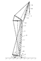
図1に本発明の一実施形態に係るクレーン立組方法よって組み立てられるクレーンの構成を示す。
[crane]
FIG. 1 shows the configuration of a crane assembled by the crane erecting method according to an embodiment of the present invention.
このクレーンは、下部走行体1と、下部走行体1上に水平方向に旋回可能に搭載される上部旋回体2と、上部旋回体2の前部に、前後方向に起伏(前側に倒伏、後側に起立するよう揺動)可能に配設されるブーム3と、ブーム3の先端に前後方向に起伏可能に連結されるジブ4とを備えるラッフィングジブクレーンである。
This crane has a
〔下部走行体〕
下部走行体1は、走行装置として一対のクローラー(履帯)5を有する。
[Lower traveling body]
The lower
〔上部旋回体〕
上部旋回体2は、操縦者用キャビン6、ブーム3を起伏させるブーム起伏ウインチ7、ジブ4を起伏させるジブ起伏ウインチ8、ジブ4の先端から垂下され、吊り荷を吊り上げるロープを巻上げる巻上げウインチ9等が設けられている。
[Upper rotating body]
The upper revolving
〔ブーム〕
ブーム3は、下部ブーム10、複数の中間ブーム11及びタワーキャップ12を長手方向に順番に接続して形成され、下部ブーム10が上部旋回体2に取り付けられ、タワーキャップ12にジブ4が連結される。下部ブーム10及び複数の中間ブーム11は、4本の主桁(柱)と、隣接する主桁間を接続する複数の補桁(ラチス)とを有し、概略四角筒状の骨組み構造体とされたラチス構造を有する。
〔boom〕
The
〔ジブ〕
ジブ4は、複数のパーシャルジブ(下部ジブ13、複数の中間ジブ14及び上部ジブ15)を長手方向に接続して形成され、下部ジブ13がブーム3の先端に連結される。これらのパーシャルジブ13,14,15は、4本の主桁(柱)と、隣接する主桁間を接続する複数の補桁(ラチス)とを有し、概略四角筒状又は四角錐状の骨組み構造体とされたラチス構造を有する。
〔jib〕
The
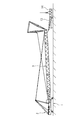
パーシャルジブ13,14,15は、図2に詳しく示すように、互いに接続される側の端部(下部ジブ13の先端、中間ジブ14の両端、上部ジブ15の基端)の背側及び腹側に突設される背側コネクタ16及び腹側コネクタ17を有する。これらのパーシャルジブ13,14,15は、図3にさらに詳しく示すように、背側コネクタ16及び腹側コネクタ17に起伏の軸に平行に、つまり水平方向に固定ピン18が挿入されることにより互いに接続される。また、腹側コネクタ17には、図4に示すように、車輪19を取り付けることができる。
As shown in detail in FIG. 2, the
(コネクタ)
背側コネクタ16及び腹側コネクタ17は、パーシャルジブ13,14,15の主桁の端部から長手方向に突出するよう設けられる1又は複数の板状体とすることができる。互いに接続される背側コネクタ16同士及び腹側コネクタ17同士は、水平方向に隣接して配置されるよう位置をずらして配設される。また、互いに接続される一対の背側コネクタ16及び一対の腹側コネクタ17は、それぞれ少なくとも一方が水平方向に間隔を空けて突設される複数の板状体から形成され、この複数の板状体の間に対をなす背側コネクタ16又は腹側コネクタ17が嵌合するよう構成されることが好ましい。
(connector)
The
(車輪)
車輪19は、腹側コネクタ17の固定ピン18が挿入される穴に挿入される軸19aを有し、この軸19aを中心に回転する。このため、軸19aは、例えば軸受け、ブッシング等を介して設けられることが好ましい。また、軸19aは、腹側コネクタ17を貫通して突出する先端部に例えばピン、止め輪等の抜け止めを装着可能に構成されることが好ましい。
(Wheel)
The
[クレーン立組方法]
本発明の一実施形態に係るクレーン立組方法は、ブーム3を上部旋回体2に組み付けた後、ブーム3の先端にパーシャルジブ13,14,15を1本ずつ順番に接続することによってジブ4を組み立てる。
[Crane assembly method]
In the crane erecting method according to the embodiment of the present invention, the
つまり、当該クレーン立組方法は、ブーム3を上部旋回体2に組み付ける工程〔ブーム組み付け工程〕と、ブーム3の先端に下部ジブ13を起伏可能に連結する工程〔下部ジブ接続工程〕と、下部ジブ13に中間ジブ14を接続又は下部ジブ13に接続された1又は複数の中間ジブ14の最先端にさらなる中間ジブ14を接続する工程〔中間ジブ接続工程〕と、下部ジブ13に接続された複数の中間ジブ14の最先端に上部ジブ15を接続する工程〔上部ジブ接続工程〕とを備える。中間ジブ接続工程は、中間ジブ14の数に応じて複数回繰り返され得る。
That is, the crane erecting method includes a step of assembling the
〔ブーム組み付け工程〕
ブーム組み付け工程は、一般的な平組の場合と同様に、ブーム3を地面上に倒伏した状態で組み立てて上部旋回体2に取り付ける。また、上部旋回体2に下部ブーム10を取り付けた後、複数の中間ブーム11及びタワーキャップ12を順に取り付けてもよい。
Boom Assembly Process
In the boom assembling step, the
〔下部ジブ接続工程〕
下部ジブ接続工程は、組み立て用クレーンを用いて、ブーム3の先端に下部ジブ13を取り付ける。この下部ジブ接続工程は、下部ジブ13を水平に吊り上げて行うことができるよう、ブーム3の先端を僅かに持ち上げた状態で行うことが好ましい。
[Lower jib connection process]
In the lower jib connection process, the
〔中間ジブ接続工程〕
中間ジブ接続工程は、下部ジブ13を1本目として数える自然数nを用いて表すと、ブーム3にn本のパーシャルジブ(下部ジブ13又は下部ジブ13及び1又は複数の中間ジブ14)が接続された状態で、n本目のパーシャルジブ(下部ジブ13又は下部ジブ13に接続されている中間ジブ14のうち最先端の中間ジブ14)の先端にn+1本目のパーシャルジブ(さらなる中間ジブ14)を接続する工程である。
[Intermediate jib connection process]
In the middle jib connection process, n partial jibs (
中間ジブ接続工程(n+1本目のパーシャルジブを接続する工程)は、ブーム3の先端を地面から離間した状態で、ブーム3に連結されたn本目のパーシャルジブ13,14の先端を地面に配置した台座S上に載置する工程<載置工程>と、n+1本目のパーシャルジブ14を吊り上げた状態で、n本目のパーシャルジブ13,14の先端側の背側コネクタ16にn+1本目のパーシャルジブ14の基端側の背側コネクタ16を接続する工程<背側コネクタ接続工程>と、n+1本目のパーシャルジブ14の先端側の腹側コネクタ17に車輪19を取り付ける工程<車輪取付工程>と、n本目のパーシャルジブ13,14の先端側の腹側コネクタ17とn+1本目のパーシャルジブ14の基端側の腹側コネクタ17とを接続する工程<腹側コネクタ接続工程>とを有する。
In the middle jib connecting step (the step of connecting the (n + 1) th partial jib), the distal ends of the nth
中間ジブ接続工程は、次の中間ジブ接続工程又は上部ジブ接続工程のために、腹側コネクタ接続工程後に、ブーム3を起こすことにより、n+1本目のパーシャルジブ14の基端側の背側コネクタを接続する背側コネクタ接続工程でn本目のパーシャルジブ13,14の先端が載置されていた位置の近傍に、n+1本目のパーシャルジブ14の先端を移動させる工程<先端移動工程>をさらに有することが好ましい。
In the middle jib connection step, the rear end connector of the proximal end side of the n + 1st
<載置工程>
載置工程では、先ず、図5に示すように、n本目のパーシャルジブ13,14の先端部を組み立て用クレーンで吊り上げながら、ブーム3を僅かに起こしてブーム3の先端が地面から離間した状態とする。
<Placement process>
In the mounting step, first, as shown in FIG. 5, the
次いで、図6に示すように、組み立て用クレーンのロープを送出して、n本目のパーシャルジブ13,14の先端を地面から浮かせるよう、地面に配置した台座Sの上に載置する。このとき、n本目のパーシャルジブ13,14の先端側の背側コネクタ16の高さが、n+1本目のパーシャルジブ14を地面に直接載置した場合の基端側の背側コネクタ16の高さよりも高くなるよう、台座Sの高さを選択する。
Next, as shown in FIG. 6, the rope of the assembly crane is sent out and placed on the pedestal S disposed on the ground so that the tips of the n-th
<背側コネクタ接続工程>
背側コネクタ接続工程では、図7に示すように、組み立て用クレーンでn+1本目のパーシャルジブ14を吊り上げて、n本目のパーシャルジブ13,14の背側コネクタ16にn+1本目のパーシャルジブ14の背側コネクタ16を位置合わせする。この状態で、両者の背側コネクタ16に固定ピン18を挿入することによって、n本目のパーシャルジブ13,14の背側コネクタ16にn+1本目のパーシャルジブ14の背側コネクタ16を接続する。
<Back side connector connection process>
In the back side connector connecting step, as shown in FIG. 7, the assembling crane lifts the (n + 1) th
<車輪取付工程>
車輪取付工程では、図8に示すように、組み立て用クレーンにより吊り上げた状態のn+1本目のパーシャルジブ14の先端側の腹側コネクタ17に車輪19を取り付ける。そして、組み立て用クレーンのロープを送出して、図9に示すように、車輪19を接地させる。つまり、車輪19によって+1本目のパーシャルジブ14の先端側の重量を支える。
<Wheel mounting process>
In the wheel attachment process, as shown in FIG. 8, the
<腹側コネクタ接続工程>
腹側コネクタ接続工程では、図10に示すように、組み立て用クレーンによって、n本目のパーシャルジブ13,14とn+1本目のパーシャルジブ14との接続部の近傍を吊り上げることにより、n本目のパーシャルジブ13,14をブーム3の先端を中心に起立方向に揺動させる。これに伴って、n+1本目のパーシャルジブ14の基端側の背側コネクタ16が持ち上げられるので、n+1本目のパーシャルジブ14は倒伏方向に揺動する。これにより、背側コネクタ16に挿入された固定ピン18を中心として、n本目のパーシャルジブ14の先端側の腹側コネクタ17とn+1本目のパーシャルジブ14の基端側の腹側コネクタ17とが重なり合うよう移動する。重なり合ったn本目のパーシャルジブ14の先端側の腹側コネクタ17とn+1本目のパーシャルジブ14の基端側の腹側コネクタ17との両方を貫通するよう固定ピン18を挿入することで、n本目のパーシャルジブ13,14の先端に、n+1本目のパーシャルジブ14が固定される。
<Abdominal connector connection process>
In the belly side connector connecting step, as shown in FIG. 10, the assembly crane lifts the vicinity of the connection portion between the nth
このとき、n+1本目のパーシャルジブ14の基端側の背側コネクタ16がブーム3の先端を中心とする円弧を描くように移動するため、n+1本目のパーシャルジブ14の先端部の位置が変化するが、n+1本目のパーシャルジブ14の先端部は車輪19によって支持されているため、n+1本目のパーシャルジブ14の先端部が地面に沿ってスムーズに移動する。これにより、作業が容易となると共に、n+1本目のパーシャルジブ14の先端部の損傷を防止することができる。
At this time, the
<先端移動工程>
先端移動工程では、図11に示すように、ブーム3を起こすことにより、ブーム3の先端に連結されている複数のパーシャルジブ13,14の接続体の基端部を持ち上げてn+1本目のパーシャルジブ14の先端部を引き寄せる。
<Tip movement process>
In the tip moving step, as shown in FIG. 11, by raising the
これにより、n+1本目のパーシャルジブ14の先端にn+2本目のパーシャルジブ14を接続するために上述の中間ジブ接続工程を繰り返す際に、図12に示すように、載置工程において台座Sを略同じ位置に配置して、この台座の上にn+1本目のパーシャルジブ14の先端を載置できるようにする。つまり、この先端移動工程を行うことによって、中間ジブ接続工程を繰り返す度に組み立て用クレーンの配置を変える必要がなくなるので、比較的小型の組み立て用クレーンであっても、組み立て用クレーンを同じ場所に固定したままジブ4の組み立てを行うことができる。なお、台座Sは既に取り付けられているパーシャルジブ13,14の合計長さに応じて適宜高さを変更してもよい。
Thereby, when repeating the above-mentioned middle jib connection process in order to connect the (n + 2) th
また、車輪19は、次の載置工程においてn+1本目のパーシャルジブ14の先端を字面状に配置した台座S上に載置する前に取り外し、車輪取付工程においてn+2本目のパーシャルジブ14の先端に取り付けられる車輪19として繰り返し使用される。
In addition, the
〔上部ジブ接続工程〕
上部ジブ接続工程は、ブーム3の先端を地面から離間した状態で、最先端のパーシャルジブ14の先端を地面に配置した台座上に載置する工程<載置工程>と、上部ジブ15を吊り上げた状態で、最先端の中間ジブ14の先端側の背側コネクタ16に上部ジブ15の基端側の背側コネクタ16を接続する工程<背側コネクタ接続工程>と、上部ジブ15の先端部に車輪20を取り付ける工程<車輪取付工程>と、最先端の中間ジブ14の先端側の腹側コネクタ17と上部ジブ15の基端側の腹側コネクタ17とを接続する工程<腹側コネクタ接続工程>とを有する。
[Upper jib connection process]
The upper jib connecting step is a step of placing the tip of the foremost
上部ジブ接続工程における載置工程、背側コネクタ接続工程、車輪取付工程及び腹側コネクタ接続工程は、車輪取付工程において、例えば図13に示すように、腹側コネクタ17に取り付けられる車輪19とは異なる車輪20を上部ジブ15の先端部に取り付ける点を除いて、中間ジブ接続工程における載置工程、背側コネクタ接続工程、車輪取付工程及び腹側コネクタ接続工程と同様の手順で行うことができる。
The mounting step in the upper jib connecting step, the back side connector connecting step, the wheel mounting step and the ventral side connector connecting step are, for example, as shown in FIG. It can carry out by the procedure similar to the mounting process in the middle jib connection process, the back side connector connection process, the wheel attachment process, and the belly side connector connection process except that
上部ジブ15の先端部に車輪20を取り付けるために上部ジブ15の先端部腹側に専用のブラケット等を設けてもよく、車輪20として上部ジブ15の先端部を支持可能な台車を用いてもよい。また、車輪20は、腹側コネクタ17に取り付けられる車輪19に上部ジブ15の先端部に取り付けるためのアダプターを装着したものであってもよい。
In order to attach the
<利点>
当該クレーン立組方法は、上述のようにパーシャルジブ13,14,15を1本ずつブーム3に接続し、ブーム3に接続されたパーシャルジブの合計長さに応じてブーム3を起こすことによって、必要とされる作業スペースの水平方向の長さを小さくすることができる。つまり、当該クレーン組み立て方法は、ブーム3及びジブ4の合計長さよりも長さが小さい場所でもクレーンを組み立てることができる。
<Advantage>
The crane erecting method connects the
また、当該クレーン立組方法は、新たに接続するn+1本目のパーシャルジブ14の先端側の腹側コネクタ17に車輪19を取り付けることによって、n+1本目のパーシャルジブ14の先端を地面に預けたまま移動させることができる。このため、n本目のパーシャルジブ13の腹側コネクタ17とn+1本目のパーシャルジブ14の基端側の腹側コネクタ17とを接続する際にn+1本目のパーシャルジブ14の先端側を吊上げる必要がないので、組み立て作業が容易且つ安全であると共に、1台の組み立て用クレーンだけで作業を行うことができる。
In addition, the crane erecting method moves the tip of the (n + 1) th
また、図1のクレーンの構成は、一般的なラッフィングジブクレーンの構成である。当該クレーン立組方法は、クレーンに特殊な構成を設けることを必要とせず、腹側コネクタ17に取り付け可能な車輪19を用意するだけでよい。このため、当該クレーン立組方法は、一般的なラッフィングジブクレーンの組み立てに広く適用することができるので、汎用性が高い。
Further, the configuration of the crane in FIG. 1 is a configuration of a general luffing jib crane. The crane erecting method does not require the crane to be provided with a special configuration, and only needs to provide
[その他の実施形態]
上記実施形態は、本発明の構成を限定するものではない。従って、上記実施形態は、本明細書の記載及び技術常識に基づいて上記実施形態各部の構成要素の省略、置換又は追加が可能であり、それらは全て本発明の範囲に属するものと解釈されるべきである。
Other Embodiments
The above embodiment does not limit the configuration of the present invention. Therefore, the above-mentioned embodiment can omit, substitute or add the components of each part of the above-mentioned embodiment based on the description of the present specification and technical common sense, and all of them are interpreted as belonging to the scope of the present invention It should.
当該クレーン立組方法において、1本目のパーシャルジブは、下部ジブと1又は複数の中間ジブを接続したものであってもよく、n+1本目のパーシャルジブは、複数の中間ジブの接続体であってもよい。 In the crane erecting method, the first partial jib may be a connection of the lower jib and one or more intermediate jibs, and the (n + 1) th partial jib is a connection of the plurality of intermediate jibs. It is also good.
当該クレーン立組方法において、先にn+1本目のパーシャルジブの先端側の腹側コネクタに車輪を取り付け、後からn本目のパーシャルジブの先端側の背側コネクタにn+1本目のパーシャルジブの基端側の背側コネクタを接続してもよい。このように、先にn+1本目のパーシャルジブの先端側の腹側コネクタに車輪を取り付ける場合、パーシャルジブを組み立て用クレーンで吊り上げなくても、パーシャルジブを台座等に載置して先端側を浮かせた状態で車輪を取り付けることもできる。 In the crane erecting method, first attach the wheel to the ventral connector on the tip side of the n + 1st partial jib, and then on the proximal end of the n + 1st partial jib on the spine connector on the tip end of the nth partial jib The back connector of may be connected. Thus, when attaching a wheel to the belly side connector of the tip side of the (n + 1) th partial jib first, the partial jib is placed on a pedestal or the like to lift the tip side without lifting the partial jib with the assembly crane. It is also possible to attach the wheel in a state of
当該クレーン立組方法の載置工程では、次の背側コネクタ取り付け工程でn本目のパーシャルジブの先端側の背側コネクタにn+1本目のパーシャルジブの基端側の背側コネクタを接続できるのであれば、n本目のパーシャルジブを直接地面に載置してもよい。 In the mounting step of the crane erecting method, the back connector of the proximal end of the (n + 1) th partial jib can be connected to the back connector of the distal end of the nth partial jib in the subsequent rear connector mounting step. For example, the n-th partial jib may be placed directly on the ground.
当該クレーン立組方法において、複数組の車輪を使用してもよい。このように、複数組の車輪を使用することによって、n+1本目のパーシャルジブの取り付け作業中にn+2本目のパーシャルジブ先端側の腹側コネクタに車輪を取り付けることができるので、作業がスムーズとなる。 In the crane erection method, multiple sets of wheels may be used. As described above, by using a plurality of sets of wheels, the wheels can be attached to the ventral connector on the tip end side of the (n + 2) th partial jib during the attachment work of the (n + 1) th partial jib, so the work becomes smooth.
当該クレーン立組方法において、先端移動工程は、腹側コネクタ接続工程の前に行ってもよく、腹側コネクタ接続工程と同時に行ってもよい。 In the crane erecting method, the tip moving step may be performed before the ventral connector connecting step or may be performed simultaneously with the ventral connector connecting step.
当該クレーン立組方法は、使用中にブームを起伏しないタワークレーンの組み立てにも適用することができる。 The crane erection method can also be applied to the assembly of a tower crane that does not lift the boom during use.
本発明に係るクレーン立組方法は、大型のラッフィングジブクレーンに特に好適に利用される。 The crane erecting method according to the present invention is particularly suitably used for a large luffing jib crane.
1 下部走行体
2 上部旋回体
3 ブーム
4 ジブ
5 クローラー
6 操縦者用キャビン
7 ブーム起伏ウインチ
8 ジブ起伏ウインチ
9 巻上げウインチ
10 下部ブーム
11 中間ブーム
12 タワーキャップ
13 下部ジブ(パーシャルジブ)
14 中間ジブ(パーシャルジブ)
15 上部ジブ(パーシャルジブ)
16 背側コネクタ
17 腹側コネクタ
18 固定ピン
19 車輪
19a 軸
20 車輪
S 台座
14 Middle jib (partial jib)
15 upper jib (partial jib)
16 back
Claims (3)
上記旋回体上に起伏可能に配設されるブームと、
上記ブームの先端に起伏可能に連結されるジブと
を備え、
上記ジブが、複数のパーシャルジブを長手方向に接続して形成され、
上記複数のパーシャルジブが、互いに接続される側の端部の背側及び腹側に突設され、起伏の軸に固定ピンが挿入されることにより互いに接続される背側コネクタ及び腹側コネクタを有するクレーンを組み立てる方法であって、
自然数nを用いて表すと、上記ブームにn本の上記パーシャルジブが接続された状態で、n本目の上記パーシャルジブの先端にn+1本目の上記パーシャルジブを接続する工程を備え、
上記n+1本目の上記パーシャルジブを接続する工程が、
上記ブームの先端を地面から離間した状態で、上記ブームに連結されたn本目の上記パーシャルジブの先端を地面に又は地面から浮かせて載置する工程と、
n+1本目の上記パーシャルジブを吊り上げた状態で、n本目の上記パーシャルジブの先端側の背側コネクタにn+1本目の上記パーシャルジブの基端側の背側コネクタを接続する工程と、
n+1本目の上記パーシャルジブの先端側の腹側コネクタに車輪を取り付ける工程と、
n本目の上記パーシャルジブ及びn+1本目の上記パーシャルジブ間の接続部近傍を吊り上げることにより、n本目の上記パーシャルジブの腹側コネクタとn+1本目の上記パーシャルジブの基端側の上記腹側コネクタとを接続する工程と
を有することを特徴とするクレーン立組方法。 A horizontally rotatable swivel body,
A boom disposed movably on the rotating body;
And a jib which is undulatingly connected to the tip of the boom,
The jib is formed by connecting a plurality of partial jibs in the longitudinal direction,
The plurality of partial jibs are provided on the back and ventral sides of the ends connected to each other, and the back connector and the vent connector are connected to each other by inserting the fixing pin into the shaft of the relief. A method of assembling a crane having
In the state where n pieces of the partial jib are connected to the boom, it is provided with a step of connecting the (n + 1) th partial jib to the tip of the nth partial jib in a state where n natural partial n is used.
The step of connecting the (n + 1) th partial jib
Placing the tip of the n-th partial jib connected to the boom above the ground or on the ground with the tip of the boom being separated from the ground;
connecting the proximal end back connector of the (n + 1) th partial jib to the distal connector of the distal end side of the nth partial jib while lifting the (n + 1) th partial jib;
attaching a wheel to the ventral connector on the tip side of the (n + 1) th partial jib;
By lifting up the vicinity of the connection between the n-th partial jib and the n + 1-th partial jib, the belly-side connector of the n-th partial jib and the belly-side connector at the proximal end of the n + 1-th partial jib And C. connecting the two.
Priority Applications (3)
| Application Number | Priority Date | Filing Date | Title |
|---|---|---|---|
| JP2017242108A JP6638718B2 (en) | 2017-12-18 | 2017-12-18 | Crane erecting method |
| US16/214,579 US10526176B2 (en) | 2017-12-18 | 2018-12-10 | Crane assembling method |
| EP18211224.3A EP3498655B1 (en) | 2017-12-18 | 2018-12-10 | Crane assembling method |
Applications Claiming Priority (1)
| Application Number | Priority Date | Filing Date | Title |
|---|---|---|---|
| JP2017242108A JP6638718B2 (en) | 2017-12-18 | 2017-12-18 | Crane erecting method |
Publications (2)
| Publication Number | Publication Date |
|---|---|
| JP2019108201A true JP2019108201A (en) | 2019-07-04 |
| JP6638718B2 JP6638718B2 (en) | 2020-01-29 |
Family
ID=64664095
Family Applications (1)
| Application Number | Title | Priority Date | Filing Date |
|---|---|---|---|
| JP2017242108A Active JP6638718B2 (en) | 2017-12-18 | 2017-12-18 | Crane erecting method |
Country Status (3)
| Country | Link |
|---|---|
| US (1) | US10526176B2 (en) |
| EP (1) | EP3498655B1 (en) |
| JP (1) | JP6638718B2 (en) |
Cited By (1)
| Publication number | Priority date | Publication date | Assignee | Title |
|---|---|---|---|---|
| CN112830400A (en) * | 2021-02-01 | 2021-05-25 | 浙江三一装备有限公司 | Crawler crane and crane transportation method |
Families Citing this family (3)
| Publication number | Priority date | Publication date | Assignee | Title |
|---|---|---|---|---|
| JP7126981B2 (en) * | 2019-03-29 | 2022-08-29 | 住友重機械建機クレーン株式会社 | crane |
| CN111422763B (en) * | 2019-12-13 | 2021-11-26 | 武汉检安石化工程有限公司 | Suspension arm assembling method under condition that obstacles exist in rod assembling area |
| DE102021106745A1 (en) * | 2021-03-19 | 2022-09-22 | Liebherr-Werk Nenzing Gmbh | Lifting gear with a device for supporting or fully automatically carrying out an erecting and/or laying down process of a boom system and a corresponding method |
Citations (8)
| Publication number | Priority date | Publication date | Assignee | Title |
|---|---|---|---|---|
| JPS60122791U (en) * | 1984-01-27 | 1985-08-19 | 日立建機株式会社 | Mobile crane with split crane boom |
| JPH10194677A (en) * | 1997-01-14 | 1998-07-28 | Tadano Ltd | Luffing jib supporting device in boom crane provided with luffing jib |
| JPH10316366A (en) * | 1997-05-21 | 1998-12-02 | Tadano Ltd | Luffing jib assembling method |
| JP2012116607A (en) * | 2010-11-30 | 2012-06-21 | Hitachi Sumitomo Heavy Industries Construction Crane Co Ltd | Mobile crane, and method of assembling the same |
| JP2014065573A (en) * | 2012-09-26 | 2014-04-17 | Kobelco Cranes Co Ltd | Lower gib |
| WO2015069096A1 (en) * | 2013-11-08 | 2015-05-14 | Itrec B.V. | Crane boom segment for assembly of a crane boom, method for assembling a crane boom |
| JP2016040204A (en) * | 2007-11-29 | 2016-03-24 | マニタウォック クレイン カンパニーズ, エルエルシーManitowoc Crane Companies, Llc | Connection system for crane boom segments |
| JP2017137164A (en) * | 2016-02-03 | 2017-08-10 | コベルコクレーン株式会社 | Method for mounting jib of crane |
Family Cites Families (17)
| Publication number | Priority date | Publication date | Assignee | Title |
|---|---|---|---|---|
| US3083837A (en) * | 1961-01-31 | 1963-04-02 | Thew Shovel Co | Crane |
| US3263383A (en) * | 1962-07-16 | 1966-08-02 | Edward T Foster | Safety carriage for crane booms |
| US3306470A (en) * | 1965-01-25 | 1967-02-28 | Robert A Green | Folding boom for mobile cranes |
| US3794184A (en) * | 1973-01-15 | 1974-02-26 | Joyce Burroughs Torregrossa | Crane |
| US3945333A (en) | 1974-12-20 | 1976-03-23 | Harnischfeger Corporation | Means for storing and connecting jib for telescopic boom of mobile crane |
| JP3980123B2 (en) * | 1996-04-26 | 2007-09-26 | マニタウォック クレイン カンパニーズ インコーポレイテッド | Boom hoist cylinder crane |
| US6481202B1 (en) * | 1997-04-16 | 2002-11-19 | Manitowoc Crane Companies, Inc. | Hydraulic system for boom hoist cylinder crane |
| WO2004087557A1 (en) * | 2003-04-02 | 2004-10-14 | Terex-Demag Gmbh & Co. Kg | Two-piece main boom for a latice-boom crane and method for erection thereof |
| JP5046599B2 (en) | 2006-09-27 | 2012-10-10 | 株式会社タダノ | Crane luffing jib equipment |
| DE102007056289B4 (en) * | 2007-10-29 | 2009-06-04 | Liebherr-Werk Ehingen Gmbh | Method for erecting a crane jib |
| DE102007051539C5 (en) * | 2007-10-29 | 2018-04-12 | Liebherr-Werk Ehingen Gmbh | Method for erecting a crane jib |
| DE102009010452A1 (en) * | 2009-02-26 | 2010-09-02 | Terex-Demag Gmbh | Method and device for mounting and dismounting an attachment on the main boom of a mobile crane |
| US8684197B2 (en) * | 2009-05-01 | 2014-04-01 | Manitowoc Crane Companies, Llc | Crane with boom raising assist structure |
| US9206021B2 (en) * | 2012-09-26 | 2015-12-08 | Kobelco Cranes Co., Ltd. | Crane and crane assembling method |
| JP6004537B2 (en) * | 2013-03-18 | 2016-10-12 | コベルコ建機株式会社 | jib |
| DE102014012422B4 (en) * | 2014-08-20 | 2023-02-09 | Liebherr-Werk Ehingen Gmbh | Automatic erection of a crane |
| EP3259435A2 (en) * | 2015-02-18 | 2017-12-27 | Stoof E EN I B.V. | Method for assembling a crane and method for operating a crane |
-
2017
- 2017-12-18 JP JP2017242108A patent/JP6638718B2/en active Active
-
2018
- 2018-12-10 US US16/214,579 patent/US10526176B2/en active Active
- 2018-12-10 EP EP18211224.3A patent/EP3498655B1/en active Active
Patent Citations (8)
| Publication number | Priority date | Publication date | Assignee | Title |
|---|---|---|---|---|
| JPS60122791U (en) * | 1984-01-27 | 1985-08-19 | 日立建機株式会社 | Mobile crane with split crane boom |
| JPH10194677A (en) * | 1997-01-14 | 1998-07-28 | Tadano Ltd | Luffing jib supporting device in boom crane provided with luffing jib |
| JPH10316366A (en) * | 1997-05-21 | 1998-12-02 | Tadano Ltd | Luffing jib assembling method |
| JP2016040204A (en) * | 2007-11-29 | 2016-03-24 | マニタウォック クレイン カンパニーズ, エルエルシーManitowoc Crane Companies, Llc | Connection system for crane boom segments |
| JP2012116607A (en) * | 2010-11-30 | 2012-06-21 | Hitachi Sumitomo Heavy Industries Construction Crane Co Ltd | Mobile crane, and method of assembling the same |
| JP2014065573A (en) * | 2012-09-26 | 2014-04-17 | Kobelco Cranes Co Ltd | Lower gib |
| WO2015069096A1 (en) * | 2013-11-08 | 2015-05-14 | Itrec B.V. | Crane boom segment for assembly of a crane boom, method for assembling a crane boom |
| JP2017137164A (en) * | 2016-02-03 | 2017-08-10 | コベルコクレーン株式会社 | Method for mounting jib of crane |
Cited By (1)
| Publication number | Priority date | Publication date | Assignee | Title |
|---|---|---|---|---|
| CN112830400A (en) * | 2021-02-01 | 2021-05-25 | 浙江三一装备有限公司 | Crawler crane and crane transportation method |
Also Published As
| Publication number | Publication date |
|---|---|
| EP3498655B1 (en) | 2020-06-24 |
| JP6638718B2 (en) | 2020-01-29 |
| US10526176B2 (en) | 2020-01-07 |
| EP3498655A1 (en) | 2019-06-19 |
| US20190185297A1 (en) | 2019-06-20 |
Similar Documents
| Publication | Publication Date | Title |
|---|---|---|
| JP2019108201A (en) | Vertically assembling method of crane | |
| EP1735233B1 (en) | Mobile crane system comprising a mobile crane and an auxiliary device for assembly of a bracing device | |
| JP4857880B2 (en) | Mobile crane boom mounting method and boom mounting tool | |
| JP2014144853A (en) | Boom and boom hoisting member | |
| JP2019069838A (en) | Crane and jib assembling method | |
| US10640341B2 (en) | Method for raising raisable and lowerable member, and crane | |
| JP6645222B2 (en) | How to attach a crane jib | |
| JP2010018355A (en) | Boom derricking device | |
| JP5540875B2 (en) | Hook part holder and hook device of wheel crane | |
| JP6683086B2 (en) | Mobile crane assembly method | |
| JP6984395B2 (en) | Crane and crane assembly method | |
| JP6202080B2 (en) | crane | |
| JP2017137171A (en) | Crane and method for mounting boom of crane | |
| JP7416034B2 (en) | How to assemble the crane | |
| JP6658020B2 (en) | Crane and crane assembling method | |
| JP6246707B2 (en) | Boom mounting device and crane | |
| JP2017145094A (en) | Wheel device of crane | |
| JP7234811B2 (en) | A crane strut, a method for folding a crane strut, and a method for assembling a crane strut | |
| JP7163607B2 (en) | Crane and crane assembly method | |
| JP6579172B2 (en) | Crane and crane strut raising method | |
| JP6720990B2 (en) | Tension member support device and tension member disassembling method | |
| JP6776740B2 (en) | How to attach / detach the winch to the work machine and the main body of the work machine | |
| JP2018048015A (en) | Method for assembling mobile crane | |
| JP6642543B2 (en) | Hanging tools | |
| JP2019177969A (en) | Crane and crane assembling method |
Legal Events
| Date | Code | Title | Description |
|---|---|---|---|
| A621 | Written request for application examination |
Free format text: JAPANESE INTERMEDIATE CODE: A621 Effective date: 20181121 |
|
| A977 | Report on retrieval |
Free format text: JAPANESE INTERMEDIATE CODE: A971007 Effective date: 20190906 |
|
| A131 | Notification of reasons for refusal |
Free format text: JAPANESE INTERMEDIATE CODE: A131 Effective date: 20190917 |
|
| A521 | Request for written amendment filed |
Free format text: JAPANESE INTERMEDIATE CODE: A523 Effective date: 20191113 |
|
| TRDD | Decision of grant or rejection written | ||
| A01 | Written decision to grant a patent or to grant a registration (utility model) |
Free format text: JAPANESE INTERMEDIATE CODE: A01 Effective date: 20191126 |
|
| A61 | First payment of annual fees (during grant procedure) |
Free format text: JAPANESE INTERMEDIATE CODE: A61 Effective date: 20191209 |
|
| R150 | Certificate of patent or registration of utility model |
Ref document number: 6638718 Country of ref document: JP Free format text: JAPANESE INTERMEDIATE CODE: R150 |