EP1735233B1 - Mobile crane system comprising a mobile crane and an auxiliary device for assembly of a bracing device - Google Patents
Mobile crane system comprising a mobile crane and an auxiliary device for assembly of a bracing device Download PDFInfo
- Publication number
- EP1735233B1 EP1735233B1 EP05748071A EP05748071A EP1735233B1 EP 1735233 B1 EP1735233 B1 EP 1735233B1 EP 05748071 A EP05748071 A EP 05748071A EP 05748071 A EP05748071 A EP 05748071A EP 1735233 B1 EP1735233 B1 EP 1735233B1
- Authority
- EP
- European Patent Office
- Prior art keywords
- guying
- boom
- assembly
- mobile crane
- guying assembly
- Prior art date
- Legal status (The legal status is an assumption and is not a legal conclusion. Google has not performed a legal analysis and makes no representation as to the accuracy of the status listed.)
- Expired - Fee Related
Links
Images


Classifications
-
- B—PERFORMING OPERATIONS; TRANSPORTING
- B66—HOISTING; LIFTING; HAULING
- B66C—CRANES; LOAD-ENGAGING ELEMENTS OR DEVICES FOR CRANES, CAPSTANS, WINCHES, OR TACKLES
- B66C23/00—Cranes comprising essentially a beam, boom, or triangular structure acting as a cantilever and mounted for translatory of swinging movements in vertical or horizontal planes or a combination of such movements, e.g. jib-cranes, derricks, tower cranes
- B66C23/18—Cranes comprising essentially a beam, boom, or triangular structure acting as a cantilever and mounted for translatory of swinging movements in vertical or horizontal planes or a combination of such movements, e.g. jib-cranes, derricks, tower cranes specially adapted for use in particular purposes
- B66C23/36—Cranes comprising essentially a beam, boom, or triangular structure acting as a cantilever and mounted for translatory of swinging movements in vertical or horizontal planes or a combination of such movements, e.g. jib-cranes, derricks, tower cranes specially adapted for use in particular purposes mounted on road or rail vehicles; Manually-movable jib-cranes for use in workshops; Floating cranes
- B66C23/42—Cranes comprising essentially a beam, boom, or triangular structure acting as a cantilever and mounted for translatory of swinging movements in vertical or horizontal planes or a combination of such movements, e.g. jib-cranes, derricks, tower cranes specially adapted for use in particular purposes mounted on road or rail vehicles; Manually-movable jib-cranes for use in workshops; Floating cranes with jibs of adjustable configuration, e.g. foldable
-
- B—PERFORMING OPERATIONS; TRANSPORTING
- B66—HOISTING; LIFTING; HAULING
- B66C—CRANES; LOAD-ENGAGING ELEMENTS OR DEVICES FOR CRANES, CAPSTANS, WINCHES, OR TACKLES
- B66C23/00—Cranes comprising essentially a beam, boom, or triangular structure acting as a cantilever and mounted for translatory of swinging movements in vertical or horizontal planes or a combination of such movements, e.g. jib-cranes, derricks, tower cranes
- B66C23/62—Constructional features or details
- B66C23/82—Luffing gear
- B66C23/821—Bracing equipment for booms
- B66C23/826—Bracing equipment acting at an inclined angle to vertical and horizontal directions
- B66C23/828—Bracing equipment acting at an inclined angle to vertical and horizontal directions where the angle is adjustable
Definitions
- the present invention relates to a mobile crane system.
- a mobile crane has a boom which can be erected in various luffing positions.
- a mobile crane of the mobile crane system according to the present invention is also equipped with a guying assembly adapted for the guying of the crane boom.
- an attachment means is present on the boom with the aid of which the guying assembly can be releasably mounted on the mobile crane boom.
- the invention also relates to a guying assembly of a crane boom of a mobile crane adapted for performing the mounting or removing without the aid of an auxiliary crane.
- the present invention also relates to a mobile transportation apparatus which in turn is intended for the transport of a guying assembly form mobile crane and on the other hand is adapted for the mounting or the removing of the guying assembly without the aid of an auxiliary crane on or from the boom of the mobile crane to be guyed.
- the invention relates to both a method for mounting and a method for removing a guying assembly of a mobile crane.
- This type of guying which reduces bending in the luffing plane, may be applied to a telescopic boom crane alone, but it may also be applied in the context of the arrangement of an additional fly jib mounted on the telescopic boom, such as a rigid or luffing latticework fly jib.
- Such a guying assembly with a gantry is shown, for example, in the prospectus by Mannesmann Demag printechnik, Demac AC 1600; 04/06, pp. 5, 17 and 27 or in DE 31 13 763 A1 .
- the above described superlift guying assembly only reduces bending in the luffing plane of the crane boom, i.e. that plane which is formed by the boom pin the various steep positions.
- Terex-Demag GmbH & Co. KG / Germany has developed the above described guying assembly in such a way that now the boom is also made rigid with respect to lateral deformations, which helps to achieve considerable increases in bearing load, in particular in steep positions of the boom of the telescopic boom crane.
- the guying assembly which is an entirely new development, has two separate guying arms that can be brought into a laterally protruding operational position, in particular, into a "V" position.
- guying arms in their operational position, form an angle of between 0° and 90° to the luffing plane.
- a guying assembly is described, for example, in EP 1 065 166 A1 .
- the references DE 200 23 223 U1 and DE 200 22 790 U1 also show such guying assemblies.
- guying assemblies having laterally protruding guying arms can achieve considerable increases in the hearing load, in particular in steep positions of a boom of a telescopic boom crane when compared with the guying assemblies, as explained above, using a gantry.
- SSL guying assemblies can also function as a gantry when the guying arms have an essentially 0° position with respect to the luffing plane. This is why in due course, modifications of this guying assembly have been developed such as described in DE 202 03 443 U1 or EP 1 342 692 A2 .
- Both the guying assemblies having a gantry and guying assemblies having two separate guying arms which can be brought into laterally protruding positions can be mounted on the boom of a mobile crane as separate guying assemblies.
- the initially mentioned Demag ⁇ C 1600 telescopic boom crane has a guying assembly wherein a frame can be removed from the boom together with the gantry. To do this, it is necessary, however, to use an additional crane for removal or mounting in order to mount or to remove the guying assembly with the gantry on or from the boom of the telescopic boom crane.
- One of the exemplary embodiments of a guying assembly with guying arms which can be brought into laterally protruding positions according to R EP 1 065 166 A2 comprises a frame with the guying arms pivotably arranged thereon. This frame can be bolted to the telescopic boom in a releasable manner.
- an auxiliary crane is necessary, which involves additional cost and also increases rigging times for such modern telescopic boom cranes with lateral guying.
- a hook block or the hoist line must be offset since otherwise the mounting of such prior art guying assemblies is not possible. After the completed mounting of this guying assembly on the buxom, the hoist line must be passed over it to the head of the boom.
- the guying arms lying on a low bed truck or the like are lifted by the telescopic boom on which they arc to be mounted itself and placed on consoles arranged by the telescopic boom crane or its carrier in predetermined positions. Then the telescopic boom is lowered so that it lies between the guying arms positioned on the consoles. Then the guying arms are mounted on the telescopic boom.
- FR 2 759 040 A1 shows a crane of which the boom is mounted to a chassis unit, hinged about a point.
- a trailer carries a transit frame.
- the frame and the chassis unit are connected at release points, and hinged arms are connected to the boom and the trailer bed.
- To dismount the boom it is released at the point and a jack is extended, causing the boom to move on the hinged arms to rise and then drop onto the transit frame, with assistance from the jack.
- a guying assembly for a telescopic boom is not provided.
- a mobile crane comprising a detachable telescopic boom is shown in DE 101 36 263 A1 (corresponds to US 2002027118 A ).
- a part of the telescopic boom rests on a semitrailer and can be connected with a base portion of the telescope boom of the mobile crane by lifting it with the mobile crane boom itself.
- a guying assembly to be mounted on the telescopic boom is not provided.
- US 5,642,821 shows a mobile crane including an undercarriage or lower crane carrying chassis, an upper load lifting and carrying chassis pivotally mounted on the lower chassis, a cab located on the upper chassis for operating the crane, a base section that can be swivelled about a horizontal axis, and a separate boom attachable to a free or operating end of the base section.
- the base section has a special construction such that with it alone especially crane operations can be performed. Attachment devices for attaching the separate boom are provided on the free end of the base section.
- the telescopic boom sections can be deposited on a semitrailer.
- DE 200 02 748 U1 discloses a mobile crane comprising a guying assembly consisting of at least two guying elements.
- the two guying elements are connected to each other by a hinged cross member.
- the guying assembly can be turned over such that it rests on the telescopic boom during transportation. Such a guying assembly cannot be dismounted from the telescopic boom.
- DE 28 33 535 shows a mobile crane comprising two independent mobile transport units which can be combined with each other.
- One mobile transport unit comprises at least one removable boom.
- the other mobile transport unit comprises a mobile crane chassis with a rotating deck arranged thereon.
- the boom can be removably mounted on the rotating deck.
- US 6,089,388 discloses a mobile crane with a rotating deck supported on the vehicle chassis with a hoist mechanism on which rotating deck the fulcrum part of a telescoping jib which can be swivelled by hydraulic rams is supported.
- a counter-jib is provided on which ballast can be hung. To intall the counter-jib, it is placed by an auxiliary crane onto the retracted telescope jib lowered onto the vehicle in such a way that a supporting frame of the counter jib can be bolted to the rotating deck at a connecting point located on the rotating deck in the area of fulcrum of the fulcrum part of the telescoping jib.
- a telescope crane for heavy loads comprising a telescopic boom, which is adapted to be coupled to a revolving superstructure and to be detaches from it for transporting.
- the boom vehicle is provided in its forward portion with a coupling structure for retaining a telescopically extensible part of the telescopic boom, and is provided in its rear portion with a lifting structure for supporting the boom.
- the lifting structure is so arranged that when it has been longitudinally aligned with the revolving superstructure, a coupling yoke, provided at the lower end of the telescopic boom, is adapted to be displaced by expending and retracting cylinders along tracks provided on the revolving superstructure to a position in which bearing eyes of the telescopic beam register with bearing bores oft he revolving superstructure.
- the revolving superstructure is provided with a pivot pin for coupling the boom to the revolving superstructure.
- AT-B-334220 discloses a mounting assistance apparatus for removable assemblies of trucks, trailers or semi-trailers.
- a mobile crane system comprising a mobile crane.
- the mobile crane has a crane boom, a guying assembly with at least one guying element for guying the crane boom and an attachment means on the crane boom with the aid of which the guying assembly can be mounted on the crane boom in a releasable manner.
- the invention is based upon the idea of mounting the guying assembly as a whole on the crane boom in a releasable manner, but to hold the entire guying assembly in a mounting height by means of a mounting assistance apparatus so that the crane boom itself may be introduced underneath it in order to be connected to or released from it.
- a mounting assistance apparatus so that the crane boom itself may be introduced underneath it in order to be connected to or released from it.
- a guying assembly can be one of the various embodiments mentioned above.
- a guying assembly for a mobile crane System according to the present invention can be a gantry.
- a guying assembly may also be used with two guying elements in the form of the two individual guying arms.
- the guying assembly in either variant may comprise all the hydraulic cylinders for erecting the guying elements and/or the electrical or control elements necessary for the Operation of the guying assembly.
- An advantage of the latter exemplary embodiment of the present invention with two guying arms is that, unlike the EP 1 342 692 A2 , each guying arm does not have to be individually mounted, but that the two may be commonly mounted on or removed from the boom in one rigging step.
- a boom of a mobile crane for the mobile crane system according to the present Invention may either he a telescopic boom or a lattice boom of a mobile crane.
- Another aspect of the present invention relates to a method of mounting a guying assembly on a boom of a mobile crane.
- Such a method according to the present invention can comprise, for example, the following process steps.
- the guying assembly is lifted on a hoist line to a mounting height by means of the same mobile crane on the boom of which the guying assembly is to be mounted.
- the guying assembly being lifted to the mounting height is held at this height by means of struts.
- the guying assembly is then released by the hoist line of the mobile crane and the boom introduced underneath the guying assembly. Then the guying assembly is connected to the boom.
- Another exemplary embodiment of the method according to the present invention provides that the struts are pivoted from a transportation position into the supporting position after the guying assembly has been raised.
- Another exemplary embodiment of the method according to the present invention provides that the struts are mounted on the guying assembly after it has been raised.
- the guying assembly is attached at at least three spaced suspension points.
- the suspension points are positioned in such a way that the guying assembly can be lifted in an essentially horizontal position.
- the guying assembly assumes an inclined position and that it is supported in this inclined position.
- Another aspect of the present invention relates to a method of removing a guying assembly from a boom of a mobile crane.
- Such a method according to the present invention can comprise, for example, the following process steps.
- the boom is brought into an essentially horizontal luffing position.
- the guying assembly is brought into a transportation position, and the boom is introduced underneath the mounting assistance apparatus while the guying assembly is in the transportation position. Then the guying assembly is released from the boom and the boom is removed from under the mounting assistance apparatus.
- Another exemplary embodiment of the removing method according to the present invention provides that the guying assembly is lifted with the aid of the same mobile crane and is placed on the mobile transportation apparatus.
- the guying assembly has two guying arms which can be brought into at least one laterally protruding guying position and that the guying arms are folded back into the transportation position.
- the guying assembly can be lifted into an essentially horizontal or inclined position and be supported there. The same also applies to the removing method.
- Another exemplary embodiment of the removing method according to the present invention provides that the guying assembly is lifted to the mounting height by means of a lifting means provided on and attached to a mobile transportation apparatus.
- the guying assembly can be lifted to the mounting height by the same mobile crane on which the guying assembly is to be mounted.
- in can be raised to the mounting height by a lifting means present on the transportation apparatus.
- a boom can principally be a telescopic boom and a lattice boom.
- a telescopic boom comprises a base section arranged on the superstructure of a mobile crane with telescopic sections extensible from and retractable into said base section.
- a lattice boom can consist of a plurality of lattice sections which, mounted one after the other, form the boom.
- Both a telescopic boom and a lattice boom can be extended by a fly jib. The fly jib is in turn attachable on the boom in a rigid or luffable manner.
- FIG. 1 a first group of various exemplary embodiments of the present invention will be described in more detail.
- two or more counterweights 3 are on a semitrailer 1 which are to be mounted on a superstructure 5 of a mobile crane 7.
- a guying assembly 9 is transported on the counterweights 3, which will be described in more detail with reference to the other figures below.
- the semitrailer 1 is transported to the desired worksite of the mobile crane 7 with the aid of a truck 2.
- the mobile crane 7 shown here basically comprises a carrier 11 and the superstructure 5 already mentioned, which can be slewed about a vertical axis D.
- a telescopic boom 13 is luffable into various steep positions about an essentially horizontal axis.
- the telescopic boom 13 comprises a base section 15 attached on the superstructure 5 to be pivoted about the horizontal axis, and a plurality of telescopic sections 17 extensibly and retractably supported at the base section 15.
- the entire mobile crane 7 is supported via hydraulic supporting elements 19 known per se.
- an attachment means for guying assembly 9 is present at base section 15 of telescopic boom 13 of mobile crane 7.
- They may be, for example, four spaced bolting points 21, schematically shown in Fig. 6 , however only on one side of base section 15.
- the two other bolting points 21 are symmetrically arranged with respect to the longitudinal axis of boom 13 and thus hidden.
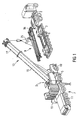
- Guying assembly 9 comprises a frame 9a on which two guying arms 9b are erectable about a transverse axis Q, and which, as will be shown below, are laterally pivotable with respect to the luffing plane.
- the hydraulic cylinders 9c and 9d necessary for erecting and laterally protruding the guying arms 9b are arranged on frame 9a.
- Four eyes 9e are also provided on the frame as attachment points. With the aid of these attachment points, the guying assembly is raised, as shown in Figs. 1 to 3 , from semitrailer 1, for example, in a position which is essentially horizontal so that struts 23 may be extended and folded down as shown in Figs. 2 and 3 .
- the mounting assistance apparatus of struts 23 may also be formed as an independent frame onto which guying assembly 9 is placed.
- struts 23 are arranged at guying assembly 9 and can be pivoted back and forth between transportation and mounting positions.
- a hoist 25 is fixed to the four attachment points 9e suspended from a load hook 27.
- Load hook 27 can be raised and lowered by means of a hoist line 29 of mobile crane 7.
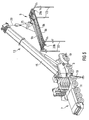
- guying assembly 9 is placed on struts 23.
- Boom 13 of mobile crane 7 is lowered in an essentially horizontal position and is in the process of being introduced underneath guying assembly 9. The introduction process is carried out until the front bolting points 21 on base section 15 come into registration with the corresponding bolting points 29a. Then the front bolting points 29a and 21 on base section 15 are bolted on to the other.
- the rear bolting points 29b on guying assembly 9 are brought into registration with the corresponding bolting points 21 at base section 15 of boom 13, and also bolted.
- struts 23 are lifted off the ground and can either be removed or folded back.
- boom 13 and guying assembly 9 now attached thereto by means of bolts is completely prepared for further rigging. All that remains is that the hydraulic and electrical connections (not shown) of guying assembly 9 be connected to the corresponding connections on mobile crane 7.
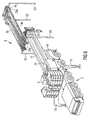
- guying assembly 9 is bolted to base section 15 in an enlarged view.
- the two guying arms 9b are pivoted into an essentially vertical position by means of hydraulic cylinders 9d.
- Guy ropes or back hitches 30, which are either connected to superstructure 5 or guying assembly 9, are pulled up.
- the free ends of guying arms 9b are connected to back hitches 30.
- back hitches 30 can have pivot links 31.
- the guying assembly 9 shown here also comprises further hydraulic cylinders 9c serving to pivot guying arms 9b to the outside, i.e. into a V-like configuration, as shown in Fig. 10 .
- guy ropes 32 connected to the free ends of guying arms 9b are connected to the front end of innermost telescopic section 17, and the telescopic sections are extended. This is followed by the lateral extension of the two guying arms 9b, as shown in Fig. 10 .
- guying assembly 9 it is also common to configure guying assembly 9 without struts 23.
- the mounting assistance apparatus comprises two struts 23 and a separate frame (not shown) on which the struts 23 are laterally pivotable and perhaps also laterally extensible.
- the lateral extension can also be provided when struts 23 are integrated in guying assembly 9.
- the mounting assistance apparatus with struts 23 and the frame is then transported on the semitrailer together with the guying assembly.
- the mounting assistance apparatus also to be placed on guying assembly 9. It is then raised in a similar way as shown in Fig. 1 and placed on struts 23. Then the guying assembly is placed on the mounting assistance apparatus with the aid of mobile crane 7. Otherwise the mounting method is carried out as shown in Figs. 2 to 10 .
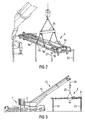
- FIG. 11 Another exemplary embodiment of the present invention is shown in Figs. 11 to 13 .
- a semitrailer 50 is shown in an elevational view, on which a lifting means 51 is mounted.
- Lifting means 51 comprises two spaced pillars 52.
- Guying assembly 9 can be raised from the transportation position as shown in Fig. 11 into the mounting position as shown in Fig. 12 by means of a hydraulic cylinder 53. It should be noted that the counterweights 3 also to be transported are not shown in Fig. 11 .
- Guying assembly 9 additionally rests on these counterweights 3. The additional weights are only shown in phantom in Fig. 11 .
- the two pillars 52 are pivotable about a pivot axis 54.
- the pillars 52 have rest surfaces 58 which are not in abutment with guying assembly 9 in the position shown in Fig. 11 , but serve as resting surfaces for guying assembly 9 in the supporting position, as shown in Fig. 12 .
- Rods 57 are linked to pillars 52 which can be bolted to base section 55.
- rods 54 are bolted to base section 55 by means of bolts 56. This serves to fix pillars 52 in the mounting position as shown in Fig. 12 .
- Guying assembly 9 has two support points or support forks 60 spaced from each other and resting on a support bolt 61 which forms a rotating support of the guying assembly about an essentially horizontal axis.
- An exemplary variant of the embodiment of a transportation apparatus 50 according to the present invention can be that guying assembly 9 rests on pillars 52 rotatably, but also fixed in height.
- a releasable fixing means is present for fixing guying assembly 9 on pillars 52 (for example a transverse bolting in each of forks 60 so that support bolts 61 are locked in forks 60).
- guying assembly 9 By lifting guying assembly 9 by means of the mobile crane (similar to the one shown in Fig. 1 ), guying assembly 9 is brought from the transportation position as shown in Fig. 11 into the mounting position of Fig. 12 and then fixed there. Then the hoist is released from guying assembly 9, and finally the introduction position as shown in Fig. 13 is assumed.
- This exemplary embodiment has the advantage that for bringing the guying assembly from the transportation position into the mounting or removing position, hydraulic cylinders or the like are not necessary, which saves costs.
- Fig. 13 again, the front bolting is carried out first, then the boom is slightly raised and the rear bolting is carried out. Then the entire guying assembly which is now bolted to telescopic boom 13 can be lifted off pillars 52. Then, again, only the hydraulic lines and/or electrical components need be connected, after which rigging can be continued.
- the removal can be done by carrying out the process steps in reversed order.
Landscapes
- Engineering & Computer Science (AREA)
- Mechanical Engineering (AREA)
- Jib Cranes (AREA)
Abstract
Description
- The present invention relates to a mobile crane system. Such a mobile crane has a boom which can be erected in various luffing positions. A mobile crane of the mobile crane system according to the present invention is also equipped with a guying assembly adapted for the guying of the crane boom. Moreover, an attachment means is present on the boom with the aid of which the guying assembly can be releasably mounted on the mobile crane boom.
- The invention also relates to a guying assembly of a crane boom of a mobile crane adapted for performing the mounting or removing without the aid of an auxiliary crane.
- The present invention also relates to a mobile transportation apparatus which in turn is intended for the transport of a guying assembly form mobile crane and on the other hand is adapted for the mounting or the removing of the guying assembly without the aid of an auxiliary crane on or from the boom of the mobile crane to be guyed.
- Finally, the invention relates to both a method for mounting and a method for removing a guying assembly of a mobile crane.
- It has been known for a long time that installing a guying assembly on the base section of the main boom of the telescopic boom crane, also known as "superlift", will increase the bearing load and reduce the bending of an extended telescopic boom of a telescopic boom crane. This well known arrangement comprises a gantry to be folded against the base section, wherein the gantry is connected, for example, to the foot section of the main boom via a guying means (boom stops) which is almost invariable in length, and with the head or collar of one of the inside telescopic sections via anther guying means (the boom pendants) variable in length. This type of guying, which reduces bending in the luffing plane, may be applied to a telescopic boom crane alone, but it may also be applied in the context of the arrangement of an additional fly jib mounted on the telescopic boom, such as a rigid or luffing latticework fly jib. Such a guying assembly with a gantry is shown, for example, in the prospectus by Mannesmann Demag Fördertechnik, Demac AC 1600; 04/06, pp. 5, 17 and 27 or in
DE 31 13 763 A1 . - However, the above described superlift guying assembly only reduces bending in the luffing plane of the crane boom, i.e. that plane which is formed by the boom pin the various steep positions. Terex-Demag GmbH & Co. KG / Germany has developed the above described guying assembly in such a way that now the boom is also made rigid with respect to lateral deformations, which helps to achieve considerable increases in bearing load, in particular in steep positions of the boom of the telescopic boom crane. The guying assembly, which is an entirely new development, has two separate guying arms that can be brought into a laterally protruding operational position, in particular, into a "V" position. This is to say that the guying arms, in their operational position, form an angle of between 0° and 90° to the luffing plane. Such a guying assembly is described, for example, in
EP 1 065 166 A1 . The referencesDE 200 23 223 U1 andDE 200 22 790 U1 also show such guying assemblies. - As has been mentioned, guying assemblies having laterally protruding guying arms can achieve considerable increases in the hearing load, in particular in steep positions of a boom of a telescopic boom crane when compared with the guying assemblies, as explained above, using a gantry. Moreover, such SSL guying assemblies can also function as a gantry when the guying arms have an essentially 0° position with respect to the luffing plane. This is why in due course, modifications of this guying assembly have been developed such as described in
DE 202 03 443 U1 orEP 1 342 692 A2 . - Both the guying assemblies having a gantry and guying assemblies having two separate guying arms which can be brought into laterally protruding positions can be mounted on the boom of a mobile crane as separate guying assemblies. For example, the initially mentioned Demag ΛC 1600 telescopic boom crane has a guying assembly wherein a frame can be removed from the boom together with the gantry. To do this, it is necessary, however, to use an additional crane for removal or mounting in order to mount or to remove the guying assembly with the gantry on or from the boom of the telescopic boom crane. One of the exemplary embodiments of a guying assembly with guying arms which can be brought into laterally protruding positions according to R
EP 1 065 166 A2 comprises a frame with the guying arms pivotably arranged thereon. This frame can be bolted to the telescopic boom in a releasable manner. In either case, for mounting or removing of the guying assembly, an auxiliary crane is necessary, which involves additional cost and also increases rigging times for such modern telescopic boom cranes with lateral guying. Finally, it must be noted that a hook block or the hoist line must be offset since otherwise the mounting of such prior art guying assemblies is not possible. After the completed mounting of this guying assembly on the buxom, the hoist line must be passed over it to the head of the boom. - In the above mentioned
EP 1 342 692 A2 , this problem has been recognized, but the alleged solution proposed therein involves extensive structural changes with respect to the above embodiments. It is proposed, for example, that the separate guying arms are placed, not mounted on a common frame, at first on consoles or comparable supports while the boom is lowered, and that they be released from the telescopic boom. The consoles or supports are arranged next to the telescopic boom at the mobile crane. Then the telescopic boom is luffed into an upper position without the guying arms. The guying arms are then picked up by the telescopic boom itself from their intermediate storage on the consoles and then loaded onto a low bed truck or the like. For the purposes of mounting, the sequence of steps is reversed. The guying arms lying on a low bed truck or the like are lifted by the telescopic boom on which they arc to be mounted itself and placed on consoles arranged by the telescopic boom crane or its carrier in predetermined positions. Then the telescopic boom is lowered so that it lies between the guying arms positioned on the consoles. Then the guying arms are mounted on the telescopic boom. - While with the above approach a separate auxiliary crane could be eliminated, the entire guying assembly had to be structurally changed. Moreover, the rigging is time-consuming since various rigging steps have to be carried out involving a plurality of lifting processes of the mobile crane, since each individual guying arm has to be picked up from the transportation apparatus and placed on the consoles. Moreover with the arrangement according to the
EP 1342 692 A2 , a plurality of hydraulic connections tor hydraulic cylinders associated with the individual guying arms have to be connected to their corresponding counterparts on the telescopic boom crane, which also increases rigging times. - For sake of completeness the following documents are referred to.
FR 2 759 040 A1 - In
US 5,484,069 a method and apparatus for self-assembling and self-disassembling a large capacity crawler crane are disclosed. The method uses the load hoist line of a crane to remove an equalizer from the boom. The method also uses a hydraulic cylinder to support, raise and lower the boom after the equalizer has been removed from the boom. Finally, the boom butt can be disassembled into several parts. - A mobile crane comprising a detachable telescopic boom is shown in
DE 101 36 263 A1 (corresponds toUS 2002027118 A ). A part of the telescopic boom rests on a semitrailer and can be connected with a base portion of the telescope boom of the mobile crane by lifting it with the mobile crane boom itself. A guying assembly to be mounted on the telescopic boom is not provided. -
US 5,642,821 shows a mobile crane including an undercarriage or lower crane carrying chassis, an upper load lifting and carrying chassis pivotally mounted on the lower chassis, a cab located on the upper chassis for operating the crane, a base section that can be swivelled about a horizontal axis, and a separate boom attachable to a free or operating end of the base section. The base section has a special construction such that with it alone especially crane operations can be performed. Attachment devices for attaching the separate boom are provided on the free end of the base section. The telescopic boom sections can be deposited on a semitrailer. - Finally,
DE 200 02 748 U1 discloses a mobile crane comprising a guying assembly consisting of at least two guying elements. The two guying elements are connected to each other by a hinged cross member. The guying assembly can be turned over such that it rests on the telescopic boom during transportation. Such a guying assembly cannot be dismounted from the telescopic boom. -
DE 28 33 535 shows a mobile crane comprising two independent mobile transport units which can be combined with each other. One mobile transport unit comprises at least one removable boom. The other mobile transport unit comprises a mobile crane chassis with a rotating deck arranged thereon. The boom can be removably mounted on the rotating deck. -
US 6,089,388 discloses a mobile crane with a rotating deck supported on the vehicle chassis with a hoist mechanism on which rotating deck the fulcrum part of a telescoping jib which can be swivelled by hydraulic rams is supported. A counter-jib is provided on which ballast can be hung. To intall the counter-jib, it is placed by an auxiliary crane onto the retracted telescope jib lowered onto the vehicle in such a way that a supporting frame of the counter jib can be bolted to the rotating deck at a connecting point located on the rotating deck in the area of fulcrum of the fulcrum part of the telescoping jib. - In
US 4,660,731 a telescope crane for heavy loads is shown comprising a telescopic boom, which is adapted to be coupled to a revolving superstructure and to be detaches from it for transporting. The boom vehicle is provided in its forward portion with a coupling structure for retaining a telescopically extensible part of the telescopic boom, and is provided in its rear portion with a lifting structure for supporting the boom. The lifting structure is so arranged that when it has been longitudinally aligned with the revolving superstructure, a coupling yoke, provided at the lower end of the telescopic boom, is adapted to be displaced by expending and retracting cylinders along tracks provided on the revolving superstructure to a position in which bearing eyes of the telescopic beam register with bearing bores oft he revolving superstructure. The revolving superstructure is provided with a pivot pin for coupling the boom to the revolving superstructure. -
AT-B-334220 - According to a first aspect of the present invention, a mobile crane system is proposed, comprising a mobile crane. In this mobile crane system, the mobile crane has a crane boom, a guying assembly with at least one guying element for guying the crane boom and an attachment means on the crane boom with the aid of which the guying assembly can be mounted on the crane boom in a releasable manner.
- The invention is based upon the idea of mounting the guying assembly as a whole on the crane boom in a releasable manner, but to hold the entire guying assembly in a mounting height by means of a mounting assistance apparatus so that the crane boom itself may be introduced underneath it in order to be connected to or released from it. This means that by using the system according to the present invention the entire guying assembly can be lifted to the desired mounting height in a single lifting operation and supported in this position by the mounting assistance apparatus so that the mounting of the guying assembly on the boom can be carried out quickly.
- A guying assembly can be one of the various embodiments mentioned above. This means that a guying assembly for a mobile crane System according to the present invention, can be a gantry. However, a guying assembly may also be used with two guying elements in the form of the two individual guying arms. In an exemplary embodiment of the present invention, the guying assembly in either variant may comprise all the hydraulic cylinders for erecting the guying elements and/or the electrical or control elements necessary for the Operation of the guying assembly. An advantage of the latter exemplary embodiment of the present invention with two guying arms is that, unlike the
EP 1 342 692 A2 , each guying arm does not have to be individually mounted, but that the two may be commonly mounted on or removed from the boom in one rigging step. It must also be noted that a boom of a mobile crane for the mobile crane system according to the present Invention may either he a telescopic boom or a lattice boom of a mobile crane. - Another aspect of the present invention relates to a method of mounting a guying assembly on a boom of a mobile crane. Such a method according to the present invention can comprise, for example, the following process steps. The guying assembly is lifted on a hoist line to a mounting height by means of the same mobile crane on the boom of which the guying assembly is to be mounted. The guying assembly being lifted to the mounting height is held at this height by means of struts. The guying assembly is then released by the hoist line of the mobile crane and the boom introduced underneath the guying assembly. Then the guying assembly is connected to the boom.
- Another exemplary embodiment of the method according to the present invention provides that the struts are pivoted from a transportation position into the supporting position after the guying assembly has been raised.
- Another exemplary embodiment of the method according to the present invention provides that the struts are mounted on the guying assembly after it has been raised.
- Another exemplary embodiment of the method according to the present invention provides that the guying assembly is attached at at least three spaced suspension points. For example, the suspension points are positioned in such a way that the guying assembly can be lifted in an essentially horizontal position. As an alternative it is conceivable, however, that the guying assembly assumes an inclined position and that it is supported in this inclined position.
- Another exemplary embodiment of a mounting method according to the present invention provides that the guying assembly is lifted to a mounting height by means of a lifting unit arranged on a mobile transportation apparatus. Then the boom of the mobile crane is introduced underneath the guying assembly held by the lifting unit. After this the guying assembly can be connected to the boom, for example, by bolting.
- Another aspect of the present invention relates to a method of removing a guying assembly from a boom of a mobile crane. Such a method according to the present invention can comprise, for example, the following process steps. The boom is brought into an essentially horizontal luffing position. The guying assembly is brought into a transportation position, and the boom is introduced underneath the mounting assistance apparatus while the guying assembly is in the transportation position. Then the guying assembly is released from the boom and the boom is removed from under the mounting assistance apparatus.
- Another exemplary embodiment of the removing method according to the present invention provides that the guying assembly is lifted with the aid of the same mobile crane and is placed on the mobile transportation apparatus.
- Another exemplary embodiment of the removing method according to the present invention provides that the guying assembly has two guying arms which can be brought into at least one laterally protruding guying position and that the guying arms are folded back into the transportation position.
- As already mentioned, according to an exemplary embodiment of the mounting method, the guying assembly can be lifted into an essentially horizontal or inclined position and be supported there. The same also applies to the removing method.
- Another exemplary embodiment of the removing method according to the present invention provides that the guying assembly is lifted to the mounting height by means of a lifting means provided on and attached to a mobile transportation apparatus.
- Basically with respect to both the mounting and the removing method, the guying assembly can be lifted to the mounting height by the same mobile crane on which the guying assembly is to be mounted. As an alternative, in can be raised to the mounting height by a lifting means present on the transportation apparatus.
- For completeness, it should finally be noted that in the present case a boom can principally be a telescopic boom and a lattice boom. A telescopic boom comprises a base section arranged on the superstructure of a mobile crane with telescopic sections extensible from and retractable into said base section. A lattice boom can consist of a plurality of lattice sections which, mounted one after the other, form the boom. Both a telescopic boom and a lattice boom can be extended by a fly jib. The fly jib is in turn attachable on the boom in a rigid or luffable manner.
- For further explanation and for a better understanding of the present invention, a number of exemplary embodiments will be described in the following with reference to the accompanying drawings, in which:
- Fig. 1
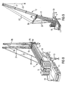
- is a schematic perspective view diagonally from the top of a mobile crane with a telescopic boom in the process of lifting a guying assembly off a semitrailer;
- Fig. 2
- is a schematic view of the guying assembly as shown in
Fig. 1 with the struts folded down; - Fig. 3
- is a schematic elevational view of the guying assembly shown in
Fig. 2 with the struts folded down; - Fig. 4
- is a detailed perspective view of the process step shown in
Fig. 1 ; - Fig. 5
- is an enlarged view of the arrangements shown in
Figs. 2 and 3 ; - Fig. 6
- is a perspective view diagonally from the top of a mobile crane with a lowered telescopic boom being introduced underneath the supported guying assembly;
- Fig. 7
- is a perspective view similar to the one of
Fig. 6 with the guying assembly mounted on the base section of the telescopic boom of the mobile crane; - Fig. 8
- is a perspective view similar to the one of
Fig. 7 with the guying arms erected; - Fig. 9
- is a perspective view similar to the one of
Figs. 7 and8 with an extended telescopic boom; - Fig. 10
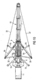
- is a plan view of a mobile crane having a guying assembly according to
Figs. 7 to 9 , with the guying arms protruding laterally, i.e. extended in a V-like configuration; - Fig. 11
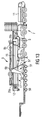
- is a schematic elevational view of a semitrailer on which a lifting means is mounted on which in turn a guying assembly lies in a transportation position;
- Fig. 12
- is an elevational view corresponding to the one of
Fig. 11 , wherein the lifting means 4 is shown in a mounting position in which the guying assembly is raised; and - Fig. 13
- is an elevational view similar to the one of
Fig. 12 , wherein the boom of a mobile crane is introduced underneath the guying assembly raised with the aid of the lifting means. - With reference to
Figs. 1 to 10 , a first group of various exemplary embodiments of the present invention will be described in more detail. In the perspective view shown inFig. 1 , two ormore counterweights 3 are on a semitrailer 1 which are to be mounted on asuperstructure 5 of amobile crane 7. A guyingassembly 9 is transported on thecounterweights 3, which will be described in more detail with reference to the other figures below. The semitrailer 1 is transported to the desired worksite of themobile crane 7 with the aid of a truck 2. - The
mobile crane 7 shown here basically comprises acarrier 11 and thesuperstructure 5 already mentioned, which can be slewed about a vertical axis D. On thesuperstructure 5, atelescopic boom 13 is luffable into various steep positions about an essentially horizontal axis. Thetelescopic boom 13 comprises abase section 15 attached on thesuperstructure 5 to be pivoted about the horizontal axis, and a plurality oftelescopic sections 17 extensibly and retractably supported at thebase section 15. In the configuration shown here, the entiremobile crane 7 is supported via hydraulic supportingelements 19 known per se. - With the exemplary embodiment of the present invention shown here, an attachment means for guying
assembly 9 is present atbase section 15 oftelescopic boom 13 ofmobile crane 7. They may be, for example, four spaced bolting points 21, schematically shown inFig. 6 , however only on one side ofbase section 15. The two other bolting points 21 are symmetrically arranged with respect to the longitudinal axis ofboom 13 and thus hidden. -
Guying assembly 9 comprises aframe 9a on which two guyingarms 9b are erectable about a transverse axis Q, and which, as will be shown below, are laterally pivotable with respect to the luffing plane. Thehydraulic cylinders arms 9b are arranged onframe 9a. Foureyes 9e are also provided on the frame as attachment points. With the aid of these attachment points, the guying assembly is raised, as shown inFigs. 1 to 3 , from semitrailer 1, for example, in a position which is essentially horizontal so that struts 23 may be extended and folded down as shown inFigs. 2 and 3 . As an alternative, the mounting assistance apparatus ofstruts 23 may also be formed as an independent frame onto which guyingassembly 9 is placed. - With the embodiment shown here, struts 23 are arranged at guying
assembly 9 and can be pivoted back and forth between transportation and mounting positions. - The individual technical details can be seen even better from the perspective view in
Fig. 4 . A hoist 25 is fixed to the fourattachment points 9e suspended from aload hook 27.Load hook 27 can be raised and lowered by means of a hoistline 29 ofmobile crane 7. - With reference to
Fig. 6 , guyingassembly 9 is placed onstruts 23.Boom 13 ofmobile crane 7 is lowered in an essentially horizontal position and is in the process of being introduced underneath guyingassembly 9. The introduction process is carried out until the front bolting points 21 onbase section 15 come into registration with thecorresponding bolting points 29a. Then thefront bolting points base section 15 are bolted on to the other. By slightly luffing upboom 13, the rear bolting points 29b on guyingassembly 9 are brought into registration with the corresponding bolting points 21 atbase section 15 ofboom 13, and also bolted. By further luffing up the boom, struts 23 are lifted off the ground and can either be removed or folded back. Then boom 13 and guyingassembly 9 now attached thereto by means of bolts is completely prepared for further rigging. All that remains is that the hydraulic and electrical connections (not shown) of guyingassembly 9 be connected to the corresponding connections onmobile crane 7. - The condition in which guying
assembly 9 is bolted tobase section 15 is also shown inFig. 7 in an enlarged view. From the basic position as shown inFig. 7 , after connecting the hydraulic connections, the two guyingarms 9b are pivoted into an essentially vertical position by means ofhydraulic cylinders 9d. Guy ropes or back hitches 30, which are either connected tosuperstructure 5 or guyingassembly 9, are pulled up. The free ends of guyingarms 9b are connected to back hitches 30. For example, back hitches 30 can havepivot links 31. - As also shown in
Fig. 8 , the guyingassembly 9 shown here also comprises furtherhydraulic cylinders 9c serving to pivot guyingarms 9b to the outside, i.e. into a V-like configuration, as shown inFig. 10 . - Once the position according to
Fig. 8 has been assumed,guy ropes 32 connected to the free ends of guyingarms 9b are connected to the front end of innermosttelescopic section 17, and the telescopic sections are extended. This is followed by the lateral extension of the two guyingarms 9b, as shown inFig. 10 . - As already mentioned, it is also common to configure guying
assembly 9 withoutstruts 23. Then the mounting assistance apparatus comprises twostruts 23 and a separate frame (not shown) on which thestruts 23 are laterally pivotable and perhaps also laterally extensible. The lateral extension can also be provided when struts 23 are integrated in guyingassembly 9. The mounting assistance apparatus withstruts 23 and the frame is then transported on the semitrailer together with the guying assembly. - It makes sense for the mounting assistance apparatus also to be placed on guying
assembly 9. It is then raised in a similar way as shown inFig. 1 and placed onstruts 23. Then the guying assembly is placed on the mounting assistance apparatus with the aid ofmobile crane 7. Otherwise the mounting method is carried out as shown inFigs. 2 to 10 . - Another exemplary embodiment of the present invention is shown in
Figs. 11 to 13 . Here, asemitrailer 50 is shown in an elevational view, on which a lifting means 51 is mounted. Lifting means 51 comprises two spacedpillars 52.Guying assembly 9 can be raised from the transportation position as shown inFig. 11 into the mounting position as shown inFig. 12 by means of ahydraulic cylinder 53. It should be noted that thecounterweights 3 also to be transported are not shown inFig. 11 .Guying assembly 9 additionally rests on thesecounterweights 3. The additional weights are only shown in phantom inFig. 11 . - The two
pillars 52 are pivotable about apivot axis 54. Thepillars 52 haverest surfaces 58 which are not in abutment with guyingassembly 9 in the position shown inFig. 11 , but serve as resting surfaces for guyingassembly 9 in the supporting position, as shown inFig. 12 .Rods 57 are linked topillars 52 which can be bolted tobase section 55. For this purpose,rods 54 are bolted tobase section 55 by means ofbolts 56. This serves to fixpillars 52 in the mounting position as shown inFig. 12 .Guying assembly 9 has two support points orsupport forks 60 spaced from each other and resting on asupport bolt 61 which forms a rotating support of the guying assembly about an essentially horizontal axis. - An exemplary variant of the embodiment of a
transportation apparatus 50 according to the present invention can be that guyingassembly 9 rests onpillars 52 rotatably, but also fixed in height. For this purpose, a releasable fixing means is present for fixing guyingassembly 9 on pillars 52 (for example a transverse bolting in each offorks 60 so thatsupport bolts 61 are locked in forks 60). By lifting guyingassembly 9 by means of the mobile crane (similar to the one shown inFig. 1 ), guyingassembly 9 is brought from the transportation position as shown inFig. 11 into the mounting position ofFig. 12 and then fixed there. Then the hoist is released from guyingassembly 9, and finally the introduction position as shown inFig. 13 is assumed. This exemplary embodiment has the advantage that for bringing the guying assembly from the transportation position into the mounting or removing position, hydraulic cylinders or the like are not necessary, which saves costs. - In
Fig. 13 , again, the front bolting is carried out first, then the boom is slightly raised and the rear bolting is carried out. Then the entire guying assembly which is now bolted totelescopic boom 13 can be lifted offpillars 52. Then, again, only the hydraulic lines and/or electrical components need be connected, after which rigging can be continued. - As has been made obvious from the explanations of the various exemplary embodiments of the present invention, the removal can be done by carrying out the process steps in reversed order.
Claims (32)
- A mobile crane system, comprising- a mobile crane (7), having:- a crane boom (13),- a guying assembly (9) with at least one guying element (9b) for guying said crane boom (13),- an attachment means (21) on the crane boom (13) with the aid of which said guying assembly (9) is releasably attachable on the crane boom (13),characterized by- a mounting assistance apparatus (23) adapted for holding said guying assembly (9) in a state apart from the crane boom (13) in a mounting position making it possible for the crane boom (13) to be introduced underneath the guying assembly (9), wherein said mounting assistance apparatus and said guying assembly (9) are configured as a structural unit which can be mounted on or removed from the crane boom (13).
- The mobile crane system according to claim 1, wherein said mounting assistance apparatus and said guying assembly (9) are separate structural units and only said guying assembly (9) is adapted to be mounted and removed.
- The mobile crane system according to claim 2, wherein said mounting assistance apparatus (52) is arranged on a mobile transportation apparatus (50).
- The mobile crane system according to any one of the preceding claims, wherein said mounting assistance apparatus has a plurality of spaced struts (23).
- The mobile crane system according to claim 4, wherein said struts (23) can be brought from a transportation position into a supporting position.
- The mobile crane system according to claim 4 or claim 5, wherein said struts (23) are pivotable at said mounting assistance apparatus (9a).
- The mobile crane system according to any one of claims 1 to 5, wherein said mounting assistance apparatus comprises a frame on which said struts (23) can be brought from a transportation position into a supporting position.
- The mobile crane system according to any one of the preceding claims, wherein said mounting assistance apparatus bas a resting means on which said guying assembly (9) can be placed.
- The mobile crane system according to any one of the preceding claims, wherein said mounting assistance apparatus comprises a pick-up means (9e) at which said mounting assistance apparatus can be raised.
- The mobile crane system according to any one of claims 1 to 9,
wherein the crane boom is a telescopic crane boom (13) having a base section (15) and a plurality of telescopic sections (17) retractable and extensible in it. - The mobile crane system according to any one of claims 1 to 9, wherein said crane boom is a lattice boom.
- The mobile crane system according to any one of claims 1 to 11, wherein said guying assembly (9) has two guying arms (9b) which can be brought from the transportation position into at least one guying position laterally protruding from said boom (13).
- The mobile crane system according to any one of claims 1 to 11, wherein said guying assembly (9) comprises a gantry which can be brought from a transportation position into at least one guying position.
- The mobile crane system according to claim 3 wherein said mounting assistance apparatus comprises a lifting means (52, 53) which is mounted on said mobile transportation apparatus (50).
- The mobile crane system according to claim 14, wherein said lifting means comprises two spaced adjustable-height pillars (52) which arc mounted on the mobile transportation apparatus (50).
- The mobile crane system according to any one of the preceding claims, wherein the guying assembly (9) is equipped with the mounting assistance apparatus in form of a support means adapted to hold the guying assembly (9) in a mounting position apart from the crane boom (13) and making it possible for the crane boom (13) to be introduced underneath the guying assembly (9).
- The mobile crane system according to claim 16, wherein the support means comprises a plurality of spaced struts (23).
- The mobile crane system according to claim 16 or claim 17, wherein said struts (23) can be brought from a transportation position into a supporting position.
- The mobile crane system according to claim 16 or claim 17, wherein said struts (23) are releasably attachable at the guying assembly (9).
- The mobile crane system according to claim 17 or claim 18, wherein said struts (23) are pivotable at said guying assembly (9).
- The mobile crane system according to any one of claims 16 to 20, wherein said guying assembly (9) comprises a pick-up means (9e) by which said guying assembly (9) can be raised.
- The mobile crane system according to claim 4, wherein said struts (23) are pivotable at the guying assembly (9).
- A method for mounting a guying assembly (9) on a boom (13) of a mobile crane (7), comprising the steps of:a) raising the guying assembly (9) to a mounting height by a hoist line (29) with the aid of the same mobile crane (7) which has the boom (13) on which the guying assembly is to be mounted;b) holding, at the mounting height, by means of struts (23), the guying assembly (9) lifted to said mounting height;c) releasing the guying assembly (9) from the hoist line (29) of the mobile crane (7);d) introducing the boom (13) of the mobile crane (7) underneath the guying assembly (9);e) connecting the guying assembly (9) to the boom (13).
- The method according to claim 23, wherein the struts (23) are pivoted from a transportation position into the supporting position after the guying assembly (9) has been raised.
- The method according to claim 23, wherein said struts (23) are attached to the guying assembly (9) after it has been raised.
- The method according to any one of claims 23 to 25, wherein the guying assembly (9) is raised while it is held at, at least, three spaced suspension points (9e) in an essentially horizontal position.
- A method of mounting a guying assembly (9) on a boom (13) of a mobile crane (7), comprising the steps of:a) lifting the guying assembly (9) to a mounting height with the aid of a lifting unit (52, 53) arranged on a mobile transportation apparatus (50);b) introducing the boom (13) of the mobile crane (7) underneath the guying assembly (9) held by the lifting unit (52, 53);c) connecting the guying assembly (9) to the boom.
- A method of mounting a guying assembly (9) on a boom (13) of a mobile crane (7), comprising the steps of:a) lifting to a mounting height the guying assembly (9) and the lifting unit (52) coupled to it, which are arranged on a mobile transportation apparatus (50), with the aid of the mobile crane (7);b) introducing the boom (13) of the mobile crane (7) underneath the guying assembly, (9) held by the lifting unit (52) fixed at said height;c) connecting the guying assembly (9) to the boom (13) and releasing the coupling between the guying assembly (9) and the lifting unit (52).
- A method for removing a guying assembly (9) mounted on a boom (13) of a mobile crane (7), comprising the steps of:a) bringing the boom (13) into an essentially horizontal luffing position;b) bringing the guying assembly (9) into a transportation position;c) introducing the boom (13) with the guying assembly (9) in the transportation position underneath a mounting assistance apparatus (23);d) releasing the guying assembly (9) from the boom (13);e) removing the boom (13) from under the mounting assistance apparatus (23).
- The method according to claim 29, wherein after step e) the guying assembly (9) is raised with the aid of the same mobile crane (7) and placed on a mobile transportation apparatus (50).
- The method according to claim 29 or claim 30, wherein the guying assembly comprise two guying arms (9b) which can be brought into at least one laterally protruding guying position, and wherein said guying arms (9b) are brought into the transportation position before step c).
- The method according to any one of claims 29 to 31, wherein the guying assembly (9) is picked up by at least three spaced suspension points (9e) in an essentially horizontal position.
Applications Claiming Priority (2)
| Application Number | Priority Date | Filing Date | Title |
|---|---|---|---|
| US55691104P | 2004-03-26 | 2004-03-26 | |
| PCT/EP2005/003121 WO2005092775A1 (en) | 2004-03-26 | 2005-03-23 | Mobile crane sytsem comprising a mobile crane and an auxiliary device for assembly of a bracing device |
Publications (2)
| Publication Number | Publication Date |
|---|---|
| EP1735233A1 EP1735233A1 (en) | 2006-12-27 |
| EP1735233B1 true EP1735233B1 (en) | 2010-09-01 |
Family
ID=34969588
Family Applications (1)
| Application Number | Title | Priority Date | Filing Date |
|---|---|---|---|
| EP05748071A Expired - Fee Related EP1735233B1 (en) | 2004-03-26 | 2005-03-23 | Mobile crane system comprising a mobile crane and an auxiliary device for assembly of a bracing device |
Country Status (3)
| Country | Link |
|---|---|
| EP (1) | EP1735233B1 (en) |
| DE (2) | DE602005023289D1 (en) |
| WO (1) | WO2005092775A1 (en) |
Families Citing this family (13)
| Publication number | Priority date | Publication date | Assignee | Title |
|---|---|---|---|---|
| DE202006007486U1 (en) * | 2006-05-10 | 2007-09-13 | Liebherr-Werk Ehingen Gmbh | Crane arm for mobile crane, has supports for supporting arm in mounting position against soil, where supports have hydro cylinder for adjusting arm length, and mounting side detachably connected with mobile crane |
| DE102008032739B4 (en) * | 2008-01-25 | 2021-10-21 | Liebherr-Werk Ehingen Gmbh | Mobile crane and method of assembly |
| DE102009020338B4 (en) | 2009-05-07 | 2011-07-21 | Manitowoc Crane Group France Sas | Telescopic crane with self-assembling guying fixture and mounting method for a guying fixture |
| US9284168B2 (en) * | 2009-10-01 | 2016-03-15 | Mw Industries, Inc. | Guyless service rig with side-mounted, pivotally deployable rear outriggers |
| US8678210B1 (en) * | 2010-11-17 | 2014-03-25 | Link-Belt Construction Equipment Co., L.P., Lllp | Telescoping boom assembly with base section having primary shell and secondary formed shell |
| US11111115B2 (en) | 2017-03-02 | 2021-09-07 | Maniitowoc Crane Companies, LLC | Wear pad with insert for telescoping boom assembly |
| DE102018115632B3 (en) | 2018-06-28 | 2019-10-10 | Manitowoc Crane Group France Sas | Telescopic boom bracing device |
| DE102018119316A1 (en) * | 2018-08-08 | 2020-02-13 | Terex Global Gmbh | Attachment part transport unit for a guy device, in particular a lateral superlift, of a mobile crane |
| DE102018133493A1 (en) | 2018-12-21 | 2020-06-25 | Tadano Demag Gmbh | Arrangement with a jib that can be luffed using two luffing cylinders and a suitably equipped mobile crane |
| DE102019120134B3 (en) * | 2019-07-25 | 2020-09-10 | Tadano Demag Gmbh | Vehicle crane and vehicle crane system as well as method for upgrading and dismantling a vehicle crane with a guy device |
| DE102020101101B3 (en) * | 2020-01-17 | 2021-05-20 | Tadano Demag Gmbh | Boom system for a vehicle crane with anchoring device as well as a method for upgrading and dismantling an anchoring device of a vehicle crane |
| DE102020119728B4 (en) | 2020-07-27 | 2022-05-25 | Manitowoc Crane Group France Sas | Crane boom transport frame |
| DE102021111922B3 (en) * | 2021-05-07 | 2022-11-03 | Liebherr-Werk Ehingen Gmbh | Guying system and method for a mobile crane telescopic boom |
Family Cites Families (14)
| Publication number | Priority date | Publication date | Assignee | Title |
|---|---|---|---|---|
| AT334220B (en) | 1974-04-30 | 1976-01-10 | Bussing & Sohn H | MECHANICAL EXCHANGE SYSTEM FOR PARKING BODIES OF TRUCKS, TRAILERS OR SEMI-TRAILERS |
| DE2833535C2 (en) | 1978-07-31 | 1983-05-11 | Mannesmann AG, 4000 Düsseldorf | Mobile crane with removable telescopic boom |
| DE3113763A1 (en) | 1981-04-04 | 1982-10-28 | Mannesmann AG, 4000 Düsseldorf | Vehicle crane with telescopic jib |
| DE3139596A1 (en) | 1981-10-05 | 1983-04-21 | Liebherr-Werk Ehingen Gmbh, 7930 Ehingen | HEAVY DUTY TELESCOPIC CRANE |
| US5484069A (en) | 1991-09-20 | 1996-01-16 | The Manitowoc Company, Inc. | Process for self-disassembling a crawler crane |
| CH686365A5 (en) | 1992-10-06 | 1996-03-15 | Werner Hofliger | Mobile crane. |
| GB2316383B (en) | 1996-08-23 | 2000-04-05 | Liebherr Werk Ehingen | Mobile crane |
| FR2759040B1 (en) | 1997-02-04 | 1999-04-30 | Ppm | METHOD AND EQUIPMENT FOR RELATIONAL FUNCTIONALITY BETWEEN THE BOOM OF A HANDLING MACHINE AND ITS CARRIER STRUCTURE |
| DE20022790U1 (en) | 1999-06-28 | 2002-07-04 | Demag Mobile Cranes Gmbh & Co | telescopic crane |
| DE20018742U1 (en) | 1999-06-28 | 2001-03-08 | Mannesmann Ag | Telescopic crane |
| DE20002748U1 (en) | 2000-02-16 | 2000-08-03 | Liebherr Werk Ehingen | Mobile crane |
| DE20013893U1 (en) | 2000-08-11 | 2001-12-13 | Liebherr Werk Ehingen | Mobile crane |
| DE20203443U1 (en) | 2002-01-02 | 2003-05-15 | Liebherr Werk Ehingen | Telescopic jib has bracing supports pivotable around only one single respective pivot point inclined do that supports spread out in V-form during orientation into operating position |
| DE50309991D1 (en) | 2002-03-04 | 2008-07-31 | Liebherr Werk Ehingen | Mobile crane with a telescopic boom and method for mounting or dismounting of guy supports of the telescopic boom |
-
2005
- 2005-03-23 DE DE602005023289T patent/DE602005023289D1/en active Active
- 2005-03-23 EP EP05748071A patent/EP1735233B1/en not_active Expired - Fee Related
- 2005-03-23 DE DE202005015044U patent/DE202005015044U1/en not_active Expired - Lifetime
- 2005-03-23 WO PCT/EP2005/003121 patent/WO2005092775A1/en not_active Application Discontinuation
Also Published As
| Publication number | Publication date |
|---|---|
| DE202005015044U1 (en) | 2005-12-22 |
| WO2005092775A1 (en) | 2005-10-06 |
| DE602005023289D1 (en) | 2010-10-14 |
| EP1735233A1 (en) | 2006-12-27 |
Similar Documents
| Publication | Publication Date | Title |
|---|---|---|
| EP1735233B1 (en) | Mobile crane system comprising a mobile crane and an auxiliary device for assembly of a bracing device | |
| US5642821A (en) | Mobile crane with improved boom construction | |
| US5484069A (en) | Process for self-disassembling a crawler crane | |
| US8839966B2 (en) | Folding jib main strut and transportable reeved strut caps | |
| CA2697321C (en) | Telescopic crane with self-mounting bracing device and method of mounting a bracing device | |
| JP5297624B2 (en) | Self-propelled lift crane equipped with variable position counterweight unit and its operating method | |
| US4700851A (en) | Lightweight, self-powered, transportable crane assembly | |
| US8690514B2 (en) | Heavy duty vehicle recovery system | |
| US3938670A (en) | Tower crane | |
| JPH1087278A (en) | Mobile crane | |
| US6702132B1 (en) | Crane self-assembly system | |
| US5348171A (en) | Removable outrigger for mobile crane | |
| US7686174B2 (en) | Vehicle crane with a telescopic boom, as well as process for assembling and disassembling the anchor supports of the telescopic boom | |
| US11753282B2 (en) | Jib system for a vehicle crane comprising a bracing apparatus and method for rigging and de-rigging a bracing apparatus of a vehicle crane | |
| US7213716B2 (en) | Crane | |
| EP2377804B1 (en) | Mobile crane, in particular mobile construction crane | |
| JPS5973352A (en) | Beam device for car and its use | |
| US20240076169A1 (en) | Vehicle crane having a detachable attachment superstructure and method for rigging the same | |
| US20220315395A1 (en) | Mobile crane, mobile crane system and method for adding and removing guying equipment to and from a mobile crane | |
| NL2030208B1 (en) | Erecting a self-climbing tower crane | |
| US4988009A (en) | Telescopic boom mobile cranes | |
| JP7146032B2 (en) | Mobile crane with separable A-frame | |
| RU2754370C1 (en) | Method for installing a crane-manipulator installation on the chassis of a truck | |
| JP2022173092A (en) | Guy system of telescopic boom of mobile crane and method thereof | |
| SU1270100A1 (en) | Device for raising and setting self-propelled boom cranes on overhead travelling crane |
Legal Events
| Date | Code | Title | Description |
|---|---|---|---|
| PUAI | Public reference made under article 153(3) epc to a published international application that has entered the european phase |
Free format text: ORIGINAL CODE: 0009012 |
|
| 17P | Request for examination filed |
Effective date: 20060724 |
|
| AK | Designated contracting states |
Kind code of ref document: A1 Designated state(s): BE DE FR GB LU NL |
|
| RBV | Designated contracting states (corrected) |
Designated state(s): BE DE FR GB LU NL |
|
| DAX | Request for extension of the european patent (deleted) | ||
| 17Q | First examination report despatched |
Effective date: 20071026 |
|
| RAP1 | Party data changed (applicant data changed or rights of an application transferred) |
Owner name: TEREX DEMAG GMBH |
|
| GRAP | Despatch of communication of intention to grant a patent |
Free format text: ORIGINAL CODE: EPIDOSNIGR1 |
|
| GRAS | Grant fee paid |
Free format text: ORIGINAL CODE: EPIDOSNIGR3 |
|
| GRAA | (expected) grant |
Free format text: ORIGINAL CODE: 0009210 |
|
| AK | Designated contracting states |
Kind code of ref document: B1 Designated state(s): BE DE FR GB LU NL |
|
| REG | Reference to a national code |
Ref country code: GB Ref legal event code: FG4D |
|
| REF | Corresponds to: |
Ref document number: 602005023289 Country of ref document: DE Date of ref document: 20101014 Kind code of ref document: P |
|
| REG | Reference to a national code |
Ref country code: NL Ref legal event code: T3 |
|
| PLBE | No opposition filed within time limit |
Free format text: ORIGINAL CODE: 0009261 |
|
| STAA | Information on the status of an ep patent application or granted ep patent |
Free format text: STATUS: NO OPPOSITION FILED WITHIN TIME LIMIT |
|
| 26N | No opposition filed |
Effective date: 20110606 |
|
| REG | Reference to a national code |
Ref country code: DE Ref legal event code: R097 Ref document number: 602005023289 Country of ref document: DE Effective date: 20110606 |
|
| REG | Reference to a national code |
Ref country code: FR Ref legal event code: ST Effective date: 20111130 |
|
| PG25 | Lapsed in a contracting state [announced via postgrant information from national office to epo] |
Ref country code: FR Free format text: LAPSE BECAUSE OF NON-PAYMENT OF DUE FEES Effective date: 20110331 |
|
| PGFP | Annual fee paid to national office [announced via postgrant information from national office to epo] |
Ref country code: GB Payment date: 20120322 Year of fee payment: 8 Ref country code: BE Payment date: 20120329 Year of fee payment: 8 |
|
| PG25 | Lapsed in a contracting state [announced via postgrant information from national office to epo] |
Ref country code: LU Free format text: LAPSE BECAUSE OF NON-PAYMENT OF DUE FEES Effective date: 20110323 |
|
| BERE | Be: lapsed |
Owner name: TEREX DEMAG G.M.B.H. Effective date: 20130331 |
|
| GBPC | Gb: european patent ceased through non-payment of renewal fee |
Effective date: 20130323 |
|
| PG25 | Lapsed in a contracting state [announced via postgrant information from national office to epo] |
Ref country code: BE Free format text: LAPSE BECAUSE OF NON-PAYMENT OF DUE FEES Effective date: 20130331 Ref country code: GB Free format text: LAPSE BECAUSE OF NON-PAYMENT OF DUE FEES Effective date: 20130323 |
|
| REG | Reference to a national code |
Ref country code: DE Ref legal event code: R082 Ref document number: 602005023289 Country of ref document: DE Representative=s name: MOSER GOETZE & PARTNER PATENTANWAELTE MBB, DE |
|
| PGFP | Annual fee paid to national office [announced via postgrant information from national office to epo] |
Ref country code: NL Payment date: 20160321 Year of fee payment: 12 |
|
| PGFP | Annual fee paid to national office [announced via postgrant information from national office to epo] |
Ref country code: DE Payment date: 20160330 Year of fee payment: 12 |
|
| REG | Reference to a national code |
Ref country code: DE Ref legal event code: R082 Ref document number: 602005023289 Country of ref document: DE Representative=s name: MOSER GOETZE & PARTNER PATENTANWAELTE MBB, DE Ref country code: DE Ref legal event code: R081 Ref document number: 602005023289 Country of ref document: DE Owner name: TEREX GLOBAL GMBH, CH Free format text: FORMER OWNER: TEREX-DEMAG GMBH, 66482 ZWEIBRUECKEN, DE |
|
| REG | Reference to a national code |
Ref country code: DE Ref legal event code: R119 Ref document number: 602005023289 Country of ref document: DE |
|
| REG | Reference to a national code |
Ref country code: NL Ref legal event code: MM Effective date: 20170401 |
|
| PG25 | Lapsed in a contracting state [announced via postgrant information from national office to epo] |
Ref country code: DE Free format text: LAPSE BECAUSE OF NON-PAYMENT OF DUE FEES Effective date: 20171003 Ref country code: NL Free format text: LAPSE BECAUSE OF NON-PAYMENT OF DUE FEES Effective date: 20170401 |