JP2011527830A - 導体間隙が縮小された超小型電子相互接続素子 - Google Patents
導体間隙が縮小された超小型電子相互接続素子 Download PDFInfo
- Publication number
- JP2011527830A JP2011527830A JP2011517428A JP2011517428A JP2011527830A JP 2011527830 A JP2011527830 A JP 2011527830A JP 2011517428 A JP2011517428 A JP 2011517428A JP 2011517428 A JP2011517428 A JP 2011517428A JP 2011527830 A JP2011527830 A JP 2011527830A
- Authority
- JP
- Japan
- Prior art keywords
- metal
- metal line
- layer
- lines
- line
- Prior art date
- Legal status (The legal status is an assumption and is not a legal conclusion. Google has not performed a legal analysis and makes no representation as to the accuracy of the status listed.)
- Pending
Links
Images


Classifications
-
- H—ELECTRICITY
- H01—ELECTRIC ELEMENTS
- H01L—SEMICONDUCTOR DEVICES NOT COVERED BY CLASS H10
- H01L23/00—Details of semiconductor or other solid state devices
- H01L23/52—Arrangements for conducting electric current within the device in operation from one component to another, i.e. interconnections, e.g. wires, lead frames
-
- B—PERFORMING OPERATIONS; TRANSPORTING
- B81—MICROSTRUCTURAL TECHNOLOGY
- B81B—MICROSTRUCTURAL DEVICES OR SYSTEMS, e.g. MICROMECHANICAL DEVICES
- B81B7/00—Microstructural systems; Auxiliary parts of microstructural devices or systems
- B81B7/0006—Interconnects
-
- H—ELECTRICITY
- H01—ELECTRIC ELEMENTS
- H01L—SEMICONDUCTOR DEVICES NOT COVERED BY CLASS H10
- H01L21/00—Processes or apparatus adapted for the manufacture or treatment of semiconductor or solid state devices or of parts thereof
- H01L21/02—Manufacture or treatment of semiconductor devices or of parts thereof
- H01L21/04—Manufacture or treatment of semiconductor devices or of parts thereof the devices having at least one potential-jump barrier or surface barrier, e.g. PN junction, depletion layer or carrier concentration layer
- H01L21/48—Manufacture or treatment of parts, e.g. containers, prior to assembly of the devices, using processes not provided for in a single one of the subgroups H01L21/06 - H01L21/326
- H01L21/4814—Conductive parts
- H01L21/4846—Leads on or in insulating or insulated substrates, e.g. metallisation
-
- B—PERFORMING OPERATIONS; TRANSPORTING
- B81—MICROSTRUCTURAL TECHNOLOGY
- B81C—PROCESSES OR APPARATUS SPECIALLY ADAPTED FOR THE MANUFACTURE OR TREATMENT OF MICROSTRUCTURAL DEVICES OR SYSTEMS
- B81C1/00—Manufacture or treatment of devices or systems in or on a substrate
- B81C1/00436—Shaping materials, i.e. techniques for structuring the substrate or the layers on the substrate
- B81C1/00523—Etching material
- B81C1/00539—Wet etching
-
- H—ELECTRICITY
- H01—ELECTRIC ELEMENTS
- H01L—SEMICONDUCTOR DEVICES NOT COVERED BY CLASS H10
- H01L21/00—Processes or apparatus adapted for the manufacture or treatment of semiconductor or solid state devices or of parts thereof
- H01L21/70—Manufacture or treatment of devices consisting of a plurality of solid state components formed in or on a common substrate or of parts thereof; Manufacture of integrated circuit devices or of parts thereof
- H01L21/71—Manufacture of specific parts of devices defined in group H01L21/70
- H01L21/768—Applying interconnections to be used for carrying current between separate components within a device comprising conductors and dielectrics
-
- H—ELECTRICITY
- H01—ELECTRIC ELEMENTS
- H01L—SEMICONDUCTOR DEVICES NOT COVERED BY CLASS H10
- H01L23/00—Details of semiconductor or other solid state devices
- H01L23/48—Arrangements for conducting electric current to or from the solid state body in operation, e.g. leads, terminal arrangements ; Selection of materials therefor
- H01L23/488—Arrangements for conducting electric current to or from the solid state body in operation, e.g. leads, terminal arrangements ; Selection of materials therefor consisting of soldered or bonded constructions
- H01L23/498—Leads, i.e. metallisations or lead-frames on insulating substrates, e.g. chip carriers
-
- H—ELECTRICITY
- H01—ELECTRIC ELEMENTS
- H01L—SEMICONDUCTOR DEVICES NOT COVERED BY CLASS H10
- H01L23/00—Details of semiconductor or other solid state devices
- H01L23/52—Arrangements for conducting electric current within the device in operation from one component to another, i.e. interconnections, e.g. wires, lead frames
- H01L23/538—Arrangements for conducting electric current within the device in operation from one component to another, i.e. interconnections, e.g. wires, lead frames the interconnection structure between a plurality of semiconductor chips being formed on, or in, insulating substrates
-
- H—ELECTRICITY
- H01—ELECTRIC ELEMENTS
- H01L—SEMICONDUCTOR DEVICES NOT COVERED BY CLASS H10
- H01L24/00—Arrangements for connecting or disconnecting semiconductor or solid-state bodies; Methods or apparatus related thereto
- H01L24/01—Means for bonding being attached to, or being formed on, the surface to be connected, e.g. chip-to-package, die-attach, "first-level" interconnects; Manufacturing methods related thereto
- H01L24/18—High density interconnect [HDI] connectors; Manufacturing methods related thereto
- H01L24/19—Manufacturing methods of high density interconnect preforms
-
- H—ELECTRICITY
- H01—ELECTRIC ELEMENTS
- H01L—SEMICONDUCTOR DEVICES NOT COVERED BY CLASS H10
- H01L24/00—Arrangements for connecting or disconnecting semiconductor or solid-state bodies; Methods or apparatus related thereto
- H01L24/01—Means for bonding being attached to, or being formed on, the surface to be connected, e.g. chip-to-package, die-attach, "first-level" interconnects; Manufacturing methods related thereto
- H01L24/18—High density interconnect [HDI] connectors; Manufacturing methods related thereto
- H01L24/23—Structure, shape, material or disposition of the high density interconnect connectors after the connecting process
- H01L24/24—Structure, shape, material or disposition of the high density interconnect connectors after the connecting process of an individual high density interconnect connector
-
- H—ELECTRICITY
- H01—ELECTRIC ELEMENTS
- H01L—SEMICONDUCTOR DEVICES NOT COVERED BY CLASS H10
- H01L2224/00—Indexing scheme for arrangements for connecting or disconnecting semiconductor or solid-state bodies and methods related thereto as covered by H01L24/00
- H01L2224/01—Means for bonding being attached to, or being formed on, the surface to be connected, e.g. chip-to-package, die-attach, "first-level" interconnects; Manufacturing methods related thereto
- H01L2224/18—High density interconnect [HDI] connectors; Manufacturing methods related thereto
- H01L2224/23—Structure, shape, material or disposition of the high density interconnect connectors after the connecting process
- H01L2224/24—Structure, shape, material or disposition of the high density interconnect connectors after the connecting process of an individual high density interconnect connector
- H01L2224/244—Connecting portions
-
- H—ELECTRICITY
- H01—ELECTRIC ELEMENTS
- H01L—SEMICONDUCTOR DEVICES NOT COVERED BY CLASS H10
- H01L2924/00—Indexing scheme for arrangements or methods for connecting or disconnecting semiconductor or solid-state bodies as covered by H01L24/00
- H01L2924/0001—Technical content checked by a classifier
- H01L2924/0002—Not covered by any one of groups H01L24/00, H01L24/00 and H01L2224/00
-
- H—ELECTRICITY
- H01—ELECTRIC ELEMENTS
- H01L—SEMICONDUCTOR DEVICES NOT COVERED BY CLASS H10
- H01L2924/00—Indexing scheme for arrangements or methods for connecting or disconnecting semiconductor or solid-state bodies as covered by H01L24/00
- H01L2924/10—Details of semiconductor or other solid state devices to be connected
- H01L2924/11—Device type
- H01L2924/12—Passive devices, e.g. 2 terminal devices
- H01L2924/1204—Optical Diode
- H01L2924/12042—LASER
Abstract
Description
本願は、2008年7月9日付け出願の米国仮特許出願第61/134,457号の出願日の利益を主張し、この出願の開示内容は参照によって本明細書に組み込まれる。
本願の主題は、超小型電子組立体およびその製造方法に関し、より具体的には、多層相互接続素子の構造体および製造方法に関する。
Claims (18)
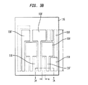
- 基準平面内に延在する幅および長さをもつ下方表面と、前記基準表面から離れている上方表面と、前記上方表面と下方表面との間に延在するエッジとを第1の金属線毎に有し、この第1の金属線の前記上方表面と前記下方表面との間の第1の距離がこの第1の金属線の厚さを画定する複数の第1の金属線と、
前記第1の金属線の前記幅の方向に前記第1の金属線とインターリーブされる複数の第2の金属線であって、前記基準平面内に延在する幅および長さをもつ上方表面と、前記基準平面から離れている下方表面とを第2の金属線毎に有し、この第2の金属線の前記上方表面と前記下方表面との間の第2の距離がこの第2の金属線の厚さを画定する複数の第2の金属線と、
前記第1の金属線のうちの金属線を前記第2の金属線のうちの隣接する金属線から分離する誘電体層と、
を備える、超小型電子相互接続素子。 - 前記第1の金属線と該第1の金属線に隣接する前記第2の金属線との間のピッチが前記第1の金属線のうちの隣接する金属線の間の第1のピッチより小さく、前記第2の金属線のうちの隣接する金属線の間の第2のピッチより小さくされている、請求項1に記載の超小型電子相互接続素子。
- 前記第1のピッチは前記第1の金属線のうちの1つの金属線の幅の少なくとも約2倍に等しく、前記第2のピッチは前記第2の金属線のうちの1つの金属線の幅の少なくとも約2倍に等しく、前記第1の金属線の前記幅の方向で、前記第1の金属線のうちの少なくとも一部は、前記第2の金属線のうちの少なくとも一部から絶縁され、前記第1の金属線のうちの1つの前記幅より遙かに小さい幅で離間されている、請求項1に記載の超小型電子相互接続素子。
- 前記第1の金属線および前記第2の金属線は、エッチングによって画定されている、請求項1に記載の超小型電子相互接続素子。
- 前記第1の金属線および前記第2の金属線のうちの少なくとも一部は、めっきによって画定されている、請求項1に記載の超小型電子相互接続素子。
- 前記第1の金属線の前記幅および前記第2の金属線の前記幅は、約60ミクロン未満である、請求項1に記載の超小型電子相互接続素子。
- 前記第1の金属線の前記幅および前記第2の金属線の前記幅は、最大で約20ミクロンである、請求項1に記載の超小型電子相互接続素子。
- 前記第1の金属線の前記幅および前記第2の金属線の前記幅は、最大で約10ミクロンである、請求項1に記載の超小型電子相互接続素子。
- 前記第2の金属線のそれぞれは、この第2の金属線の前記上方表面と前記下方表面との間に延在するエッジを有し、前記第1の金属線のうちの1つのエッジと前記第2の金属線のうちの1つの隣接するエッジとの間の間隙は、隣接する前記第1の金属線の前記幅および前記第2の金属線の前記幅より小さくされている、請求項1に記載の超小型電子相互接続素子。
- 前記基準平面の方向に延在する導電性パッドと、前記導電性パッドから前記誘電体層を通って延在する導電性ビアとをさらに備える、請求項1に記載の超小型電子相互接続素子。
- 前記導電性ビアは中実金属バンプを含み、前記導電性パッドは、前記第1の金属線のうちの少なくとも1つに接続されている金属リングと、前記金属リング内部の導電性接合剤とを含み、前記中実金属バンプは、前記導電性接合剤に接合されている、請求項10に記載の超小型電子相互接続素子。
- 前記中実金属バンプは、エッチングされた金属バンプである、請求項11に記載の超小型電子相互接続素子。
- 前記金属リングおよび前記第1の金属線は、同じ金属層から形成されている、請求項11に記載の超小型電子相互接続素子。
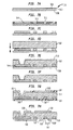
- (a)第1の露出金属層および第2の露出金属層と、前記第1の金属層と前記第2の金属層との間に挟まれたエッチングバリア層とを含む積層素子を提供するステップと、
(b)前記第1の金属線を覆う誘電体層を形成するステップと、
(c)前記第2の露出金属層をエッチングすることを含むプロセスによって第2の金属線を画定するステップと、
を含む、超小型電子相互接続素子を形成する方法。 - エッチングバリア層は導電性であり、ステップ(b)の前に前記第1の金属線の間の前記エッチングバリア層の一部分を除去するステップと、ステップ(c)の後に前記第2の金属線の間の前記エッチングバリア層の一部分を除去するステップとをさらに含む、請求項14に記載の超小型電子相互接続素子を形成する方法。
- 前記第1の金属線のうちの金属線と前記第2の金属線のうちの隣接する金属線との間のピッチが、前記第1の露出金属層をエッチングすることにより得られる前記第1の金属線の間の第1のピッチより小さく、前記第2の露出金属層をエッチングすることにより得られる前記第2の金属線の間のピッチより小さくされる、請求項14に記載の超小型電子相互接続素子を形成する方法。
- (a)第1の厚さを有する第1の露出金属薄層と、前記第1の厚さより実質的に大きい第2の厚さを有する第2の露出金属層と、前記第1の金属層と前記第2の金属層との間に挟まれた剥離可能層と含む積層素子が与えられ、複数の第1の金属線を前記第1の金属層の第1の表面にめっきするステップと、
(b)前記第1の金属線を覆う誘電体層を形成するステップと、
(c)前記第1の金属層の第2の表面を露出させるため少なくとも前記第2の金属層および前記剥離可能層を除去するステップと、
(d)複数の第2の金属線を前記第1の金属層の前記第2の表面にめっきするステップと、
(e)前記第1の金属線と前記第2の金属線との間で露出した前記第1の金属層の少なくとも一部分を除去するステップと、
を含む、超小型電子相互接続素子を形成する方法。 - 前記第1の金属線のうちの金属線と前記第2の金属線のうちの隣接する金属線との間のピッチが、めっきすることにより得られる前記第1の金属線の間のピッチより小さく、めっきにより得られる前記第2の金属線の間のピッチより小さくされる、請求項17に記載の超小型電子相互接続素子を形成する方法。
Applications Claiming Priority (3)
| Application Number | Priority Date | Filing Date | Title |
|---|---|---|---|
| US13445708P | 2008-07-09 | 2008-07-09 | |
| US61/134,457 | 2008-07-09 | ||
| PCT/US2009/004033 WO2010005592A2 (en) | 2008-07-09 | 2009-07-08 | Microelectronic interconnect element with decreased conductor spacing |
Publications (2)
| Publication Number | Publication Date |
|---|---|
| JP2011527830A true JP2011527830A (ja) | 2011-11-04 |
| JP2011527830A5 JP2011527830A5 (ja) | 2012-09-13 |
Family
ID=41396280
Family Applications (1)
| Application Number | Title | Priority Date | Filing Date |
|---|---|---|---|
| JP2011517428A Pending JP2011527830A (ja) | 2008-07-09 | 2009-07-08 | 導体間隙が縮小された超小型電子相互接続素子 |
Country Status (4)
| Country | Link |
|---|---|
| US (4) | US8461460B2 (ja) |
| JP (1) | JP2011527830A (ja) |
| KR (1) | KR101654820B1 (ja) |
| WO (1) | WO2010005592A2 (ja) |
Families Citing this family (13)
| Publication number | Priority date | Publication date | Assignee | Title |
|---|---|---|---|---|
| US7914296B1 (en) * | 2010-01-05 | 2011-03-29 | Exatron, Inc. | Interconnecting assembly with conductive lever portions on a support film |
| US9761489B2 (en) | 2013-08-20 | 2017-09-12 | Applied Materials, Inc. | Self-aligned interconnects formed using substractive techniques |
| US9159670B2 (en) * | 2013-08-29 | 2015-10-13 | Qualcomm Incorporated | Ultra fine pitch and spacing interconnects for substrate |
| US9263349B2 (en) * | 2013-11-08 | 2016-02-16 | Globalfoundries Inc. | Printing minimum width semiconductor features at non-minimum pitch and resulting device |
| US9609751B2 (en) | 2014-04-11 | 2017-03-28 | Qualcomm Incorporated | Package substrate comprising surface interconnect and cavity comprising electroless fill |
| CN105097758B (zh) * | 2014-05-05 | 2018-10-26 | 日月光半导体制造股份有限公司 | 衬底、其半导体封装及其制造方法 |
| ITUB20155408A1 (it) * | 2015-11-10 | 2017-05-10 | St Microelectronics Srl | Substrato di packaging per dispositivi a semiconduttore, dispositivo e procedimento corrispondenti |
| US11063758B1 (en) | 2016-11-01 | 2021-07-13 | F5 Networks, Inc. | Methods for facilitating cipher selection and devices thereof |
| US10636758B2 (en) * | 2017-10-05 | 2020-04-28 | Texas Instruments Incorporated | Expanded head pillar for bump bonds |
| CN109673112B (zh) * | 2017-10-13 | 2021-08-20 | 鹏鼎控股(深圳)股份有限公司 | 柔性电路板以及柔性电路板的制作方法 |
| US11018024B2 (en) * | 2018-08-02 | 2021-05-25 | Nxp Usa, Inc. | Method of fabricating embedded traces |
| US11251117B2 (en) * | 2019-09-05 | 2022-02-15 | Intel Corporation | Self aligned gratings for tight pitch interconnects and methods of fabrication |
| US11791320B2 (en) * | 2021-11-22 | 2023-10-17 | Qualcomm Incorporated | Integrated circuit (IC) packages employing a package substrate with a double side embedded trace substrate (ETS), and related fabrication methods |
Citations (7)
| Publication number | Priority date | Publication date | Assignee | Title |
|---|---|---|---|---|
| JPH03110849A (ja) * | 1989-09-25 | 1991-05-10 | Nec Corp | 半導体装置 |
| JPH08330473A (ja) * | 1995-05-31 | 1996-12-13 | Samsung Electron Co Ltd | ソルダーボールの装着溝を有する印刷回路基板とこれを使用したボールグリッドアレイパッケージ |
| US5846876A (en) * | 1996-06-05 | 1998-12-08 | Advanced Micro Devices, Inc. | Integrated circuit which uses a damascene process for producing staggered interconnect lines |
| US5854128A (en) * | 1996-04-29 | 1998-12-29 | Micron Technology, Inc. | Method for reducing capacitive coupling between conductive lines |
| JP2000031280A (ja) * | 1998-06-17 | 2000-01-28 | Siemens Ag | 集積回路のためのメタライゼ―ション装置 |
| JP2002198422A (ja) * | 2000-12-26 | 2002-07-12 | Toshiba Corp | 半導体装置およびその製造方法 |
| JP2002246466A (ja) * | 2001-02-08 | 2002-08-30 | Samsung Electronics Co Ltd | 多層配線構造を有する半導体素子及びその製造方法 |
Family Cites Families (13)
| Publication number | Priority date | Publication date | Assignee | Title |
|---|---|---|---|---|
| US5072075A (en) * | 1989-06-28 | 1991-12-10 | Digital Equipment Corporation | Double-sided hybrid high density circuit board and method of making same |
| US5440805A (en) | 1992-03-09 | 1995-08-15 | Rogers Corporation | Method of manufacturing a multilayer circuit |
| US5287619A (en) | 1992-03-09 | 1994-02-22 | Rogers Corporation | Method of manufacture multichip module substrate |
| US5509553A (en) * | 1994-04-22 | 1996-04-23 | Litel Instruments | Direct etch processes for the manufacture of high density multichip modules |
| US5995328A (en) * | 1996-10-03 | 1999-11-30 | Quantum Corporation | Multi-layered integrated conductor trace array interconnect structure having optimized electrical parameters |
| US6222136B1 (en) * | 1997-11-12 | 2001-04-24 | International Business Machines Corporation | Printed circuit board with continuous connective bumps |
| US6849923B2 (en) * | 1999-03-12 | 2005-02-01 | Kabushiki Kaisha Toshiba | Semiconductor device and manufacturing method of the same |
| JP3384995B2 (ja) * | 2000-05-18 | 2003-03-10 | 株式会社ダイワ工業 | 多層配線基板及びその製造方法 |
| US7670962B2 (en) | 2002-05-01 | 2010-03-02 | Amkor Technology, Inc. | Substrate having stiffener fabrication method |
| US20040011555A1 (en) * | 2002-07-22 | 2004-01-22 | Chiu Tsung Chin | Method for manufacturing printed circuit board with stacked wires and printed circuit board manufacturing according to the mehtod |
| JP4133560B2 (ja) * | 2003-05-07 | 2008-08-13 | インターナショナル・ビジネス・マシーンズ・コーポレーション | プリント配線基板の製造方法およびプリント配線基板 |
| TWI286916B (en) * | 2004-10-18 | 2007-09-11 | Via Tech Inc | Circuit structure |
| US20080001297A1 (en) * | 2006-06-30 | 2008-01-03 | Stefanie Lotz | Laser patterning and conductive interconnect/materials forming techniques for fine line and space features |
-
2009
- 2009-07-08 KR KR1020117003020A patent/KR101654820B1/ko active IP Right Grant
- 2009-07-08 WO PCT/US2009/004033 patent/WO2010005592A2/en active Application Filing
- 2009-07-08 US US12/459,864 patent/US8461460B2/en active Active
- 2009-07-08 JP JP2011517428A patent/JP2011527830A/ja active Pending
-
2013
- 2013-06-10 US US13/914,616 patent/US8900464B2/en active Active
-
2014
- 2014-12-01 US US14/557,120 patent/US9524947B2/en active Active
-
2016
- 2016-12-15 US US15/380,391 patent/US9856135B2/en active Active
Patent Citations (7)
| Publication number | Priority date | Publication date | Assignee | Title |
|---|---|---|---|---|
| JPH03110849A (ja) * | 1989-09-25 | 1991-05-10 | Nec Corp | 半導体装置 |
| JPH08330473A (ja) * | 1995-05-31 | 1996-12-13 | Samsung Electron Co Ltd | ソルダーボールの装着溝を有する印刷回路基板とこれを使用したボールグリッドアレイパッケージ |
| US5854128A (en) * | 1996-04-29 | 1998-12-29 | Micron Technology, Inc. | Method for reducing capacitive coupling between conductive lines |
| US5846876A (en) * | 1996-06-05 | 1998-12-08 | Advanced Micro Devices, Inc. | Integrated circuit which uses a damascene process for producing staggered interconnect lines |
| JP2000031280A (ja) * | 1998-06-17 | 2000-01-28 | Siemens Ag | 集積回路のためのメタライゼ―ション装置 |
| JP2002198422A (ja) * | 2000-12-26 | 2002-07-12 | Toshiba Corp | 半導体装置およびその製造方法 |
| JP2002246466A (ja) * | 2001-02-08 | 2002-08-30 | Samsung Electronics Co Ltd | 多層配線構造を有する半導体素子及びその製造方法 |
Also Published As
| Publication number | Publication date |
|---|---|
| US8461460B2 (en) | 2013-06-11 |
| US9524947B2 (en) | 2016-12-20 |
| KR101654820B1 (ko) | 2016-09-06 |
| WO2010005592A8 (en) | 2011-02-10 |
| WO2010005592A3 (en) | 2010-10-07 |
| US20100009554A1 (en) | 2010-01-14 |
| US8900464B2 (en) | 2014-12-02 |
| US20150087146A1 (en) | 2015-03-26 |
| KR20110039337A (ko) | 2011-04-15 |
| US9856135B2 (en) | 2018-01-02 |
| WO2010005592A2 (en) | 2010-01-14 |
| US20130341299A1 (en) | 2013-12-26 |
| US20170096329A1 (en) | 2017-04-06 |
Similar Documents
| Publication | Publication Date | Title |
|---|---|---|
| US9856135B2 (en) | Microelectronic interconnect element with decreased conductor spacing | |
| US7911805B2 (en) | Multilayer wiring element having pin interface | |
| KR101376265B1 (ko) | 배선 기판 및 그 제조 방법 | |
| JP5010737B2 (ja) | プリント配線板 | |
| US8610268B2 (en) | Semiconductor element, semiconductor element mounted board, and method of manufacturing semiconductor element | |
| JP2007311688A (ja) | 電子装置用基板およびその製造方法、並びに電子装置およびその製造方法 | |
| JP2014229689A (ja) | モジュールおよびその製造方法 | |
| JP4170266B2 (ja) | 配線基板の製造方法 | |
| JP2015144157A (ja) | 回路基板、電子装置及び電子装置の製造方法 | |
| KR100908986B1 (ko) | 코어리스 패키지 기판 및 제조 방법 | |
| JP2011035296A (ja) | 半導体パッケージ及びその製造方法、並びに電子装置 | |
| JP5295211B2 (ja) | 半導体モジュールの製造方法 | |
| KR100925669B1 (ko) | 코어리스 패키지 기판 제조 공법에 의한 솔더 온 패드 제조방법 | |
| KR100934107B1 (ko) | 미세 피치의 금속 범프를 제공하는 인쇄회로기판 제조 방법 | |
| KR101574019B1 (ko) | 인쇄회로기판의 제조 방법 | |
| TWI420989B (zh) | 印刷電路板及其製造方法 | |
| KR100997880B1 (ko) | 칩 내장 기판의 패드와 기판을 접속 제조하는 방법 및 이를적용한 다기능 인쇄회로기판 | |
| JP2004207262A (ja) | 薄膜多層回路基板及びその製造方法 | |
| JP2012204732A (ja) | 配線基板およびその製造方法 | |
| KR20200105031A (ko) | 미세 피치 회로구조를 갖는 인쇄회로기판 및 그 제조 방법 | |
| JP2013009006A (ja) | 配線基板とその製造方法 | |
| KR20100104244A (ko) | 인쇄회로기판 및 그 제조 방법 |
Legal Events
| Date | Code | Title | Description |
|---|---|---|---|
| A711 | Notification of change in applicant |
Free format text: JAPANESE INTERMEDIATE CODE: A712 Effective date: 20120516 |
|
| A521 | Request for written amendment filed |
Free format text: JAPANESE INTERMEDIATE CODE: A523 Effective date: 20120629 |
|
| A521 | Request for written amendment filed |
Free format text: JAPANESE INTERMEDIATE CODE: A523 Effective date: 20120709 |
|
| A621 | Written request for application examination |
Free format text: JAPANESE INTERMEDIATE CODE: A621 Effective date: 20120709 |
|
| A131 | Notification of reasons for refusal |
Free format text: JAPANESE INTERMEDIATE CODE: A131 Effective date: 20130903 |
|
| A601 | Written request for extension of time |
Free format text: JAPANESE INTERMEDIATE CODE: A601 Effective date: 20131203 |
|
| A602 | Written permission of extension of time |
Free format text: JAPANESE INTERMEDIATE CODE: A602 Effective date: 20131210 |
|
| A521 | Request for written amendment filed |
Free format text: JAPANESE INTERMEDIATE CODE: A523 Effective date: 20140303 |
|
| A02 | Decision of refusal |
Free format text: JAPANESE INTERMEDIATE CODE: A02 Effective date: 20140430 |