JP2010143733A - Substrate handling system and substrate handling method - Google Patents
Substrate handling system and substrate handling method Download PDFInfo
- Publication number
- JP2010143733A JP2010143733A JP2008324405A JP2008324405A JP2010143733A JP 2010143733 A JP2010143733 A JP 2010143733A JP 2008324405 A JP2008324405 A JP 2008324405A JP 2008324405 A JP2008324405 A JP 2008324405A JP 2010143733 A JP2010143733 A JP 2010143733A
- Authority
- JP
- Japan
- Prior art keywords
- substrate
- glass substrate
- arm
- transport path
- blowing
- Prior art date
- Legal status (The legal status is an assumption and is not a legal conclusion. Google has not performed a legal analysis and makes no representation as to the accuracy of the status listed.)
- Pending
Links
- 239000000758 substrate Substances 0.000 title claims abstract description 241
- 238000000034 method Methods 0.000 title claims description 12
- 238000007667 floating Methods 0.000 claims abstract description 36
- 238000007664 blowing Methods 0.000 claims description 25
- 238000005339 levitation Methods 0.000 claims description 24
- 238000012546 transfer Methods 0.000 claims description 11
- 239000011521 glass Substances 0.000 abstract description 105
- 230000007246 mechanism Effects 0.000 abstract description 17
- 230000000452 restraining effect Effects 0.000 abstract 2
- 238000012545 processing Methods 0.000 description 7
- 230000000694 effects Effects 0.000 description 4
- 238000011144 upstream manufacturing Methods 0.000 description 3
- 238000013459 approach Methods 0.000 description 1
- 230000002238 attenuated effect Effects 0.000 description 1
- 238000004891 communication Methods 0.000 description 1
- 230000008878 coupling Effects 0.000 description 1
- 238000010168 coupling process Methods 0.000 description 1
- 238000005859 coupling reaction Methods 0.000 description 1
- 238000010586 diagram Methods 0.000 description 1
- 238000006073 displacement reaction Methods 0.000 description 1
- 239000004973 liquid crystal related substance Substances 0.000 description 1
- 238000012423 maintenance Methods 0.000 description 1
- 238000004519 manufacturing process Methods 0.000 description 1
- 238000012856 packing Methods 0.000 description 1
- 239000004065 semiconductor Substances 0.000 description 1
- 230000035945 sensitivity Effects 0.000 description 1
- 238000001179 sorption measurement Methods 0.000 description 1
Images
Landscapes
- Manipulator (AREA)
- Container, Conveyance, Adherence, Positioning, Of Wafer (AREA)
Abstract
Description
本発明は、基板ハンドリングシステム及び基板ハンドリング方法に関し、特に、大型の基板を搬送等する基板ハンドリングシステム及び基板ハンドリング方法に関する。 The present invention relates to a substrate handling system and a substrate handling method, and more particularly to a substrate handling system and a substrate handling method for conveying a large substrate.
従来の基板ハンドリングシステムとしては、例えば特許文献1に記載されたものが知られている。この基板ハンドリングシステムでは、搬送路上の基板の下面に向けて送風ファンでエアを供給し、基板を浮上させる。そして、この状態で、駆動ローラによって搬送方向に基板を移動させる。これにより、基板の主面との接触を抑制しつつ、基板を搬送路上にて搬送方向に搬送することが図られている。
ここで、上述したような基板ハンドリングシステムでは、例えば基板を高速度で搬送すると、場合によっては、基板が振動して損傷してしまうおそれがある。さらに、近年の基板の大型化に伴って、搬送する基板に振動やたわみ等の変形が生じ易いという問題もある。 Here, in the substrate handling system as described above, for example, when the substrate is transported at a high speed, the substrate may vibrate and be damaged in some cases. Furthermore, with the recent increase in size of the substrate, there is a problem that deformation such as vibration and deflection is likely to occur on the substrate to be transported.
そこで、本発明は、基板の振動や変形を抑制しつつ基板を高速度で非接触に搬送することができる基板ハンドリングシステム及び基板ハンドリング方法を提供することを課題とする。 Therefore, an object of the present invention is to provide a substrate handling system and a substrate handling method that can transport a substrate in a non-contact manner at a high speed while suppressing vibration and deformation of the substrate.
上記課題を解決するため、本発明に係る基板ハンドリングシステムは、基板を搬送するための搬送路を備え、搬送路は、エアの吹出及び吸引によって搬送路上で基板を浮上保持する搬送路浮上保持手段と、基板を保持し搬送方向に沿って基板を移動させる移動手段と、を有しており、基板を搬送路浮上保持手段で変形を抑制可能に浮上保持しながら移動手段で搬送方向に搬送することを特徴とする。 In order to solve the above problems, a substrate handling system according to the present invention includes a transport path for transporting a substrate, and the transport path floats and holds the substrate on the transport path by blowing and sucking air. And a moving means for holding the substrate and moving the substrate along the carrying direction, and carrying the substrate in the carrying direction by the moving means while levitating and holding the substrate by the carrying path levitation holding means. It is characterized by that.
この基板ハンドリングシステムでは、搬送路上の基板が単に浮上されるのではなく、浮上保持、すなわち浮上されつつ充分な保持剛性(浮上高さ方向の変位に対する復元性能)でもって保持される。そして、この状態で、基板が搬送方向に沿って移動される。従って、基板を高速度で搬送しても、かかる保持剛性によって、基板の振動を抑制し且つ基板を搬送路に倣った状態にすることができる。つまり、本発明によれば、基板の振動や変形を抑制しつつ基板を高速度で搬送することが可能となる。 In this substrate handling system, the substrate on the transport path is not simply levitated, but is levitated and held, that is, held with sufficient holding rigidity (restoration performance against displacement in the levitating height direction). In this state, the substrate is moved along the transport direction. Therefore, even if the substrate is transported at a high speed, the holding rigidity can suppress the vibration of the substrate and make the substrate follow the transport path. That is, according to the present invention, the substrate can be transported at a high speed while suppressing the vibration and deformation of the substrate.
また、第1地点から第2地点へ基板を移載するためのアームをさらに備え、アームは、エアの吹出及び吸引によって基板を浮上保持するアーム浮上保持手段を有しており、基板をアーム浮上保持手段で非接触に懸垂するように浮上保持することが好ましい。このように、基板をアームで懸垂するように浮上保持して移載すると、基板をアームで下方から持ち上げて移載する場合に比べ、この浮上保持が高い保持剛性を有することから、第2地点に基板を容易に載置することができる。 The arm further includes an arm for transferring the substrate from the first point to the second point, and the arm has arm levitation holding means for levitating and holding the substrate by blowing and sucking air. It is preferable that the holding means is levitated and held so as to be suspended in a non-contact manner. Thus, when the substrate is levitated and held so as to be suspended by the arm, the levitating holding has a higher holding rigidity than the case where the substrate is lifted and transferred from below by the arm. The substrate can be easily placed on the substrate.
また、アームは、搬送路上の第1地点から第2地点へ基板を移載し、搬送路は、搬送路浮上保持手段を制御する制御手段をさらに有し、制御手段は、アームが浮上保持を解除して基板を搬送路上に載置する際、エアの吹出で基板を受け止めた後に基板を浮上保持するように搬送路浮上保持手段を制御することが好ましい。これにより、基板を搬送路上に載置するに際して、エアのクッション効果が好適に発揮され、基板に加わる力を柔らげることができる。その結果、基板が傷付くのを一層抑制することが可能となる。 The arm transfers the substrate from the first point to the second point on the transport path, the transport path further includes control means for controlling the transport path levitation holding means, and the control means holds the levitation holding arm. When releasing and placing the substrate on the transport path, it is preferable to control the transport path levitation holding means so as to float and hold the substrate after receiving the substrate by blowing air. Thereby, when the substrate is placed on the conveyance path, the cushioning effect of air is suitably exhibited, and the force applied to the substrate can be softened. As a result, it is possible to further suppress the substrate from being damaged.
また、上記作用効果を奏する構成として、具体的には、搬送路浮上保持手段及びアーム浮上保持手段のそれぞれが、複数の吹出部及び吸引部と、吹出部からエアを吹出するための吹出流路と、吸引部からエアを吸引するための吸引流路と、を含んで構成されている場合が挙げられる。 Moreover, as a structure which has the said effect, specifically, each of a conveyance path levitation | floating holding means and an arm levitation | floating holding means, the blowing flow path for blowing off air from a several blowing part and a suction part, and a blowing part And a suction flow path for sucking air from the suction part.
また、本発明に係る基板ハンドリング方法は、搬送路で基板を搬送する搬送工程を含み、搬送工程においては、エアの吹出及び吸引によって搬送路上で基板を浮上保持しながら、当該基板を搬送方向に搬送することを特徴とする。 In addition, the substrate handling method according to the present invention includes a transport step of transporting the substrate on the transport path. In the transport step, the substrate is placed in the transport direction while the substrate is levitated and held on the transport path by blowing and sucking air. It is transported.
この基板ハンドリング方法においては、搬送路上の基板が単に浮上されるのではなく、浮上保持でもって保持された状態で、基板が搬送方向に沿って移動される。従って、基板を高速度で搬送しても、基板の主面が傷付くのを確実に抑制できると共に、かかる保持剛性によって、基板の振動を抑制し且つ基板を搬送路に倣った状態にすることができる。よって、基板の振動やたわみ等の変形を抑制しつつ基板を高速度で搬送することが可能となる。 In this substrate handling method, the substrate on the transport path is not simply levitated, but the substrate is moved along the transport direction while being held in a floating state. Therefore, even if the substrate is transported at a high speed, the main surface of the substrate can be reliably prevented from being damaged, and the holding rigidity can suppress the vibration of the substrate and make the substrate follow the transport path. Can do. Therefore, the substrate can be transported at a high speed while suppressing deformation such as vibration and deflection of the substrate.
また、第1地点から第2地点へ基板をアームで移載する移載工程をさらに含み、移載工程においては、アームがエアの吹出及び吸引によって基板を非接触に懸垂するように浮上保持することが好ましい。これにより、基板をアームで下方から持ち上げて移載する場合に比べ、第2地点に基板を容易に載置することができる。 Further, the method further includes a transfer step of transferring the substrate from the first point to the second point by an arm, and the arm floats and holds the substrate so as to suspend the substrate in a non-contact manner by blowing and sucking air. It is preferable. Thereby, compared with the case where the board | substrate is lifted and transferred from the downward direction with an arm, a board | substrate can be easily mounted in a 2nd point.
本発明によれば、基板の振動や変形を抑制しつつ基板を高速度で非接触に搬送することが可能となる。 According to the present invention, it is possible to transport the substrate in a non-contact manner at a high speed while suppressing vibration and deformation of the substrate.
以下、添付図面を参照して、本発明の好適な実施形態について詳細に説明する。なお、以下において同一又は相当要素には同一符号を付し、重複する説明は省略する。また、「上」「下」等の語は、鉛直方向における上方、下方に対応するものである。ちなみに、説明の便宜上、参照する「特開2006−273576号公報」を「文献2」と称し、「特開2008−114954号公報」を「文献3」と称す。
Hereinafter, preferred embodiments of the present invention will be described in detail with reference to the accompanying drawings. In the following description, the same or corresponding elements are denoted by the same reference numerals, and redundant description is omitted. In addition, terms such as “upper” and “lower” correspond to upward and downward in the vertical direction. Incidentally, for convenience of explanation, the “JP 2006-273576 A” referred to is referred to as “
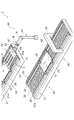
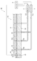
図1は、本発明の一実施形態に係る基板ハンドリングシステムを示す概略図、図2は、図1の基板ハンドリングシステムの第1搬送路を示す断面図である。図1に示すように、基板ハンドリングシステム1は、第1搬送路20、第2搬送路40、ロボットアーム装置60、及び処理テーブル80を具備しており、ガラス基板Gの加工や検査工程においてガラス基板Gをハンドリング(搬送及び移載等)する。ここでのガラス基板Gは、薄型大型テレビ等の液晶画面に用いられる非常に大型のものであり、縦2800mm×横3000mm程度のいわゆる第10世代サイズのものである。また、ガラス基板Gの厚さは、一般的に0.7mm程度である。
FIG. 1 is a schematic view showing a substrate handling system according to an embodiment of the present invention, and FIG. 2 is a cross-sectional view showing a first transfer path of the substrate handling system of FIG. As shown in FIG. 1, the
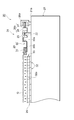
第1搬送路20は、ベース21と、駆動機構(移動手段)24と、基板浮上装置(搬送路浮上保持手段)25と、を備えている。ベース21は、外形が直方体状をなし、床面等の水平面上に載置される。このベース21の上面21aは、水平面状をなし、ガラス基板Gの搬送方向Xに沿って延在している。
The
図2に示すように、駆動機構24は、リニアモータ機構で構成され、ガイドレール22、スライダ23、固定子26a及び可動子26bを含んでいる。ガイドレール22は、搬送方向Xに延びるように、ベース21の上面21aに一対設置されている。これら一対のガイドレール22は、ガラス基板Gの幅よりも若干大きめの間隔で離間され、互いに平行に配置されている。スライダ23は、一対のガイドレール22のそれぞれに2個ずつ設けられている。これらスライダ23は、ガイドレール22にガイドされて、搬送方向Xに移動可能になっている。
As shown in FIG. 2, the
固定子26aは、一対のガイドレール22外側において当該ガイドレール22に沿うように設けられている。可動子26bは、固定子26aと作用して駆動される駆動体27と、駆動体27の両端から搬送方向Xに延設され駆動体27aとスライダ23とを連結する連結部材28と、を含んでいる。連結部材28は、スライダ23の外側面にそれぞれに固定されている。これにより、各ガイドレール22に設けられたスライダ23は、一定距離を保ったまま同期して移動する。
The
また、駆動機構24は、保持部材29を複数有している。保持部材29は、スライダ23の内側面にそれぞれ固定され、バネ板部30と吸着部31とを含んでいる。バネ板部30は、鉛直方向に沿って延びる基部30aと、幅方向(図示左右方向)に沿って延びる屈曲部30bとを含んでいる。吸着部31は、屈曲部30b上に固定されている。この保持部材29によれば、ガラス基板Gがベース21の上面21aから離間した状態にて、吸着部31によるエア引きでガラス基板Gの側縁部が吸着され保持されることとなる。
The
基板浮上装置25は、ガラス基板Gにエアを吹出し及び吸引する。基板浮上装置25は、ベース21の上面21a側において一対のガイドレール22間の全領域に敷き詰められるよう設けられている(図1参照)。
The
この基板浮上装置25は、例えば文献2に示すような構成とされ、浮上ユニット32と、定盤33とを有している。定盤33の上面は精密な水平面となるよう研磨され、浮上ユニット32で支持されている。
The
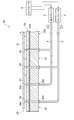
図3は、図2の第1搬送路の一部拡大図である。図3に示すように、浮上ユニット32の上面32aには、エアを吹き出すための吹出口(吹出部)34aと、エアを吸引するための吸引口(吸引部)35aとが設けられている。また、浮上ユニット32の下面32bには、エアを導入するための導入口34bと、エアを引き出すための引出口35bとが設けられている。ここでは、吹出口34a、吸引口35a、導入口34b、及び引出口35bの開口が、隣り合うようにして均等に多数配置されている。
FIG. 3 is a partially enlarged view of the first transport path of FIG. As shown in FIG. 3, the
吹出口34aと導入口34bとは、吹出流路36により連通されている。一方、吸引口35aと引出口35bとは、吸引流路37により連通されている。また、導入口34bには、導入管2を介してコンプレッサ3に接続されている。一方、引出口35bには、吸引管4を介して吸引ポンプ5に接続されている。なお、これらの流路は図示上では直線的な流路に描かれているが、圧力損失が付加されるように流路を構成してもよく(例えば、文献2参照)、その他の種々の方法で流路を構成してもよい。
The
コンプレッサ3は、加圧したエアを吹き出すための給気装置であり、吸引ポンプ5は、エアを吸引するための吸気装置である。これらコンプレッサ3及び吸引ポンプ5には、コントローラ(制御手段)6が接続されており、これにより、コンプレッサ3及び吸引ポンプ5は、そのエアの吹出し量及び吸引量が制御される。
The
定盤33は、エアを通すためのものとして、鉛直方向に延在する貫通孔38を複数有している。これらの貫通孔38は、複数の浮上ユニット32の吹出口34a及び吸引口35aに対応する数だけ、規則的に配列されて設けられている。この定盤33の上面は、平面度が高く加工されており、ガラス基板Gに対する基準面として機能している。
The
この定盤33は、複数の浮上ユニット32上に載置されており、その複数の貫通孔38が浮上ユニット32の吹出口34a及び吸引口35aにパッキン等を介して気密に連通されている。
The
図1に戻り、第2搬送路40は、上記の第1搬送路と同様な構成を備えている。すなわち、第2搬送路40にあっても、上述したベース21、ガイドレール22、スライダ23、駆動機構24及び基板浮上装置25を備えている。
Returning to FIG. 1, the
ロボットアーム装置60は、第1搬送路(第1地点)20から第2搬送路(第2地点)40へガラス基板Gを移載、つまり移動させて載置するものである。このロボットアーム装置60は、第1搬送路20の搬送方向Xにおける下流側と第2搬送路40の搬送方向Xにおける上流側との周辺に配置されている。
The
このロボットアーム装置60では、連結機構61を介して床面等に設けられた支持部62でアーム63が支持され、アーム63が軸線A回り回転方向に回転可能に構成されている。アーム63は、その一方の主面63a側でガラス基板Gを浮上保持する(以下、この「主面63a」を「浮上保持面63a」という)。
In the
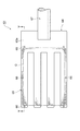
図4は、ロボットアーム装置のアームの浮上保持面側を示す図、図5は、図4のV−V線に沿っての断面図である。図4に示すように、アーム63は、本体64、基板浮上装置(アーム浮上保持手段)65及びガイドピン66を有している。
FIG. 4 is a view showing the floating holding surface side of the arm of the robot arm device, and FIG. 5 is a cross-sectional view taken along the line VV of FIG. As shown in FIG. 4, the
本体64は、その形状が板状であってもよく、先端側が複数に分かれたフォーク形状であってもよい。図4に示される例では、先端側が四つ又形状となっている。また、本体64は、浮上保持面63a視においてガラス基板Gよりも大きな面積を有している。この本体64の基端側は、可動ロッド67を介してリンク61に可動に連結されている。これにより、本体64は、その長手方向に沿う軸線B回りに回転可能に構成されている。
The
基板浮上装置65は、ガラス基板Gにエアを吹出し及び吸引するものである。この基板浮上装置65は、本体64の浮上保持面63a側において外縁部を除く全領域に敷き詰められるよう設けられている。基板浮上装置65は、上記基板浮上装置25と同様に構成されており、図5に示すように、複数の浮上ユニット32と、定盤33とを有している。
The
ガイドピン66は、浮上保持したガラス基板Gのズレ(浮上保持面63aに沿う方向の移動)を規制するものである。このガイドピン66は、浮上保持面63a側に出没可能に複数設けられている。つまり、ガイドピン66がアーム63の浮上保持面63aにて突出する状態と、ガイドピン66がアーム63内に収容される状態とが、相互に可変になっている。
The
このガイドピン66は、本体64の外縁部であって、浮上保持するガラス基板Gに対して隙間を有して囲う位置に設けられている(図4参照)。また、ガイドピン66は、コントローラ6と接続されており、これにより、その出没状態が制御される。
This
図1に示すように、処理テーブル80は、ガラス基板Gを検査・加工するためのものであり、ガントリ81を備えている。この処理テーブル80は、第2搬送路40の下流側にて当該第2搬送路40と連続するように構成され、この処理テーブル80にも、基板浮上装置25と同様な基板浮上装置が設けられている。
As shown in FIG. 1, the processing table 80 is for inspecting and processing the glass substrate G, and includes a
次に、基板浮上装置25,65によるガラス基板Gの浮上について、図3を参照しつつ詳細に説明する。
Next, the floating of the glass substrate G by the
まず、コンプレッサ3で供給されたエアが、導入管2を通して導入口34bから浮上ユニット32の吹出流路36に導入される。導入されたエアは、吹出流路36内を流れて吹出口34aを介して吹出される。吹出されたエアは、定盤33上のガラス基板Gと定盤33との隙間を通して、吸引口35aを介して吸引ポンプ5で吸引される。
First, the air supplied by the
ここで、基板浮上装置25においては、ガラス基板Gと定盤33との隙間量である浮上高さをh、隙間内の圧力をガラス基板Gの面積で積分した量をWとすると、力Wが浮上高さhで変化することで保持剛性が生じる。なお、吹出流路36に圧力損失回路を設けると、吹出口34a及び吸引口35aの形状変更により高い保持剛性が得られることがわかっている(例えば文献2,3参照)。
Here, in the
この浮上高さhの変化に基づく負荷容量Wの変化に与える感度(dW/dh)が、ガラス基板Gの保持剛性に相当する。よって、例えば、浮上高さhの僅かの変化で負荷容量Wが大きく変化すると、力のバランスが大きく崩れるため、もとの平衡位置(隙間量)にすぐに戻ろうとすることになる。つまり、隙間内のエアは、仮想的なバネとして作用し、浮上保持されたガラス基板Gは、浮上高さを変更するような外乱に対しての復元力としての保持剛性を有することになる。 The sensitivity (dW / dh) given to the change in the load capacity W based on the change in the flying height h corresponds to the holding rigidity of the glass substrate G. Therefore, for example, if the load capacity W changes greatly due to a slight change in the flying height h, the balance of the force is greatly lost, so that it will immediately return to the original equilibrium position (gap amount). That is, the air in the gap acts as a virtual spring, and the glass substrate G that is levitated and held has a holding rigidity as a restoring force against a disturbance that changes the levitating height.
なお、浮上高さhを0.1mm以下とすると、高い保持剛性が得られるため好ましい。さらに、浮上高さhを0.05mm以下とすると、一層強固な保持剛性が得られるために一層好ましい。また、保持剛性の大きさは、エアの圧力又は流量をコントローラ6で制御することによって制御可能である。
A flying height h of 0.1 mm or less is preferable because high holding rigidity can be obtained. Furthermore, it is more preferable that the flying height h is 0.05 mm or less because a stronger holding rigidity can be obtained. The magnitude of the holding rigidity can be controlled by controlling the air pressure or flow rate with the
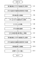
次に、基板ハンドリングシステム1を用いたガラス基板Gのハンドリング方法ついて、図6のフローチャートを参照しつつ説明する。
Next, a method for handling the glass substrate G using the
まず、基板浮上装置25を作動させてエアの吹き出し及び吸引を行い、第1搬送路20上の搬送方向Xにおける上流側にて、ガラス基板Gを水平に浮上保持する。この状態で、ガラス基板Gの側縁部を駆動機構24の保持部材29で吸着する(S2)。そして、駆動機構24によりスライダ23を移動させる。これにより、ガラス基板Gが浮上保持されながら、第1搬送路20の下流側まで搬送方向Xに沿って高速度(例えば、2.0m/s)で搬送される(S3)。
First, the
続いて、コンプレッサ3を作動させ、アーム63でエアの吹出しを行いつつ、ガラス基板Gの上面に対向するようにアーム63の浮上保持面63aを例えば数mmの位置まで接近させる。このとき、アーム63がガラス基板Gに接触しないように十分なエアの吹出しを行う。次に、吸引ポンプ5を作動させ、吸引力が徐々に大きくなるようにアーム63でエアの吸引を行う。これにより、アーム63の下側の浮上保持面63aでもってガラス基板Gの上面が非接触で懸垂されるように浮上保持される(S4)。
Subsequently, the
続いて、アーム63の本体64に収容されたガイドピン66を作動させ、浮上保持面63aからガイドピン66が突出する状態にする(S5)。そして、アーム63を上方へ移動させる。これにより、ガラス基板Gが、アーム63で非接触に懸垂されるように持ち上がる(S6)。この状態で、支持部62を回転してアーム63を軸線A回りに回転し、第2搬送路40上の搬送方向Xにおける上流側へガラス基板Gを移動させる(S7)。
Subsequently, the
なお、ここでは、アーム63が上方への移動を開始するのに先立ち、第1搬送路20の浮上装置25の吸引を止めて吹出しのみとしている。これは、ガラス基板Gを持ち上げるためにアーム63が要する力を抑制するためである。
Here, prior to the
続いて、第2搬送路40において基板浮上装置25を作動させてエアの吹出しを行うと共に、アーム63を徐々に下方に移動して、ガラス基板Gを徐々に下ろす。そして、第2搬送路40に対してガラス基板Gの下面が例えば数mmの位置まで接近したとき、アーム63におけるエアの吸引を徐々に低下させてガラス基板Gをアーム63から離す(アーム63による浮上保持の解除)。その結果、第2搬送路40上にて、アーム63から離れたガラス基板Gが水平に浮上保持されつつ載置される(S8)。
Subsequently, the
ここで、ガラス基板Gを第2搬送路40上に載置する際、第2搬送路40においては、エアの吹出し及び吸引を次のようにコントローラ6で制御する。すなわち、まずエアの吹出を行うことで、アーム63から離れたガラス基板Gを受け止める。これにより、載置の際にガラス基板Gに加わる衝撃力を柔らげる。また、アーム63の振動を減衰させる。その後、かかるエアの吹出に加えてエアの吸引を行い、ガラス基板Gを浮上保持する。
Here, when the glass substrate G is placed on the
続いて、ガラス基板Gを浮上保持した状態で、このガラス基板Gの側縁部に駆動機構24の保持部材29を吸着する(S9)。そして、駆動機構24によりスライダ23を移動させる。これにより、ガラス基板Gが浮上保持されながら、高速度で第2搬送路40の下流側まで搬送されると共に(S10)、高速度で処理テーブル80上に搬入される(S11)。
Subsequently, the holding
以上、本実施形態の基板ハンドリングシステム1では、第1及び第2搬送路20,40上の基板Gが単に浮上されるのではなく、変形を抑制可能に浮上保持される。すなわち、浮上されつつ充分な保持剛性で保持される。そして、この状態で、ガラス基板Gが搬送方向Xに沿って移動され搬送される。従って、ガラス基板Gを高速度で搬送しても、ガラス基板Gの主面が傷付くのを確実に抑制できると共に、かかる保持剛性によって、ガラス基板Gの振動を抑制し、且つガラス基板Gに初期変形があっても搬送路に倣った平面状態にすることができる。よって、本実施形態によれば、ガラス基板Gの振動やたわみ等の変形を抑制しつつガラス基板Gを高速度で搬送することが可能となる。
As described above, in the
また、ガラス基板Gを高速度で搬送できることから、ガラス基板Gのハンドリング時間の短縮化も可能となり、生産コストを低減することもできる。さらに、ガラス基板Gを浮上保持して搬送することから、ガラス基板Gの主面に汚れが付着するのを防止することもできる。 Moreover, since the glass substrate G can be conveyed at high speed, the handling time of the glass substrate G can be shortened, and the production cost can also be reduced. Further, since the glass substrate G is floated and transported, it is possible to prevent dirt from adhering to the main surface of the glass substrate G.
ちなみに、ガラス基板Gにあっては、その大きさが年々大型化しているものの、その厚さが従来と同程度であるため、ハンドリングの際にたわみ易く、振動や変形も残り易くなっている。よって、本実施形態のガラス基板Gの振動や変形を抑制するという上記効果は、特に有効なものである。 Incidentally, although the size of the glass substrate G is increasing year by year, the thickness thereof is about the same as the conventional one, so that it is easy to bend during handling, and vibration and deformation are likely to remain. Therefore, the above effect of suppressing the vibration and deformation of the glass substrate G of the present embodiment is particularly effective.
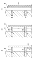
ところで、従来のアームでは、通常、第1搬送路にてガラス基板Gを下方から持ち上げ、このガラス基板Gを第2搬送路にて下ろすことによってガラス基板Gを移載する。詳言すると、図7(a),(b)に示すように、第2搬送路81においては、ガラス基板Gをアーム82から下ろすために、ガラス基板Gをリフトピン83で一旦支持する。そして、図7(c)に示すように、この支持状態で、ガラス基板Gからアーム82が引き抜かれるように離される。よって、従来のアーム82を用いてガラス基板Gを移載する場合には、ガラス基板Gがリフトピン83で傷つかないように、アーム82の振動が小さくなるまでアーム82を第2搬送路81上でしばらく停止(すなわち、アーム82を図7(a)の状態で一時停止)させる必要がある。
By the way, in the conventional arm, the glass substrate G is usually transferred by lifting the glass substrate G from below in the first transport path and lowering the glass substrate G in the second transport path. Specifically, as shown in FIGS. 7A and 7B, in the
この点、本実施形態では、上述したように、ガラス基板Gをアーム63で非接触に懸垂するように浮上保持して移載する。そのため、ガラス基板Gをアーム63から下ろすために、ガラス基板Gをリフトピン83で一旦支持する必要がなく、振動が小さくなるまでアーム63を一時停止させる必要がない。よって、ガラス基板Gを下方から持ち上げて移載する場合に比べ、ガラス基板Gを第2搬送路40に容易に載置することができると共に、スループットを向上することが可能となる。また、上記リフトピン83も不要となる。
In this regard, in this embodiment, as described above, the glass substrate G is floated and transferred so as to be suspended in a non-contact manner by the
また、本実施形態では、上述したように、アーム63が浮上保持したガラス基板Gのズレを規制するためのガイドピン66を有しているため、ガラス基板Gがズレてアームから外れるのを抑制することができる。
In the present embodiment, as described above, since the guide pins 66 for restricting the deviation of the glass substrate G that the
また、本実施形態では、上述したように、ガラス基板Gを第2搬送路40上に載置する際、エアの吹出でガラス基板Gを受け止めた後に浮上保持している。よって、ガラス基板Gを第2搬送路40上に載置するに際して、エアのクッション効果が好適に発揮され、ガラス基板Gに加わる力を柔らげることができる。その結果、ガラス基板Gが傷付くのを一層抑制することが可能となる。
Further, in the present embodiment, as described above, when the glass substrate G is placed on the
なお、本実施形態のアーム63は、上記のように、軸線B回りに回転可能に構成されている。よって、上記S4〜S6の際、アーム63の下側にガラス基板Gを懸垂するように浮上保持した後、この状態でアーム63を軸線B回りに180°回転させることで、ガラス基板Gをアーム63の上面側に浮上保持してもよい。
Note that the
以上、本発明の好適な実施形態について説明したが、本発明は上記実施形態に限定されるものではない。例えば、上記実施形態は、ガラス基板Gをハンドリングするものであるが、半導体基板等の基板をハンドリングしても勿論よい。 The preferred embodiment of the present invention has been described above, but the present invention is not limited to the above embodiment. For example, in the above-described embodiment, the glass substrate G is handled, but a substrate such as a semiconductor substrate may be handled.
また、上記実施形態では、ガラス基板Gが水平となる状態で浮上保持されるよう搬送路20,40を構成したが、垂直或いは垂直に近い状態で浮上保持されるよう搬送路20,40を構成してもよく、浮上保持されるガラス基板Gの主面の角度は限定されるものではない。例えば、垂直となるようにガラス基板Gを浮上保持すると、ガラス基板Gを鉛直搬送することが可能となり、ガラス基板Gがさらに大型化しても基板ハンドリングシステム1の占有スペースの増大を抑制することができる。
Moreover, in the said embodiment, although the
また、上記実施形態では、アーム63で第2搬送路40にガラス基板Gを移載したが、処理テーブル80にガラス基板Gを直接移載してもよい。また、基板ハンドリングシステム1が、ガラス基板Gを積層するように収納する収納カセット等をさらに備え、この収納カセット等にガラス基板Gが搬入、搬出又は移載されてもよい。
In the above embodiment, the glass substrate G is transferred to the
また、上記実施形態では、保持部材29が、ガラス基板Gの側縁部に吸着することで保持したが、ガラス基板Gの対向する側端部を挟持したり、ガラス基板Gの側縁部を上下から把持したり等することで保持してもよい。また、上記実施形態では、駆動機構24をリニアモータ機構で構成したが、駆動機構24をローラ機構等の種々の機構で構成してもよい。なお、例えばロボットアーム装置60の支持台62に車輪を設け、ロボットアーム装置60を床面上にて移動可能に構成してもよい。
Moreover, in the said embodiment, although the holding
1…基板ハンドリングシステム、6…コントローラ(制御手段)、20…第1搬送路(搬送路,第1地点)、24…駆動機構(移動手段)、25,65…基板浮上装置(搬送路浮上保持手段)、34a…吹出口(吹出部)、35a…吸引口(吸引部)、36…吹出流路、37…吸引流路、40…第2搬送路(搬送路,第2地点)、63…アーム、65…基板浮上装置(アーム浮上保持手段)、G…ガラス基板(基板)。
DESCRIPTION OF
Claims (6)
前記搬送路は、エアの吹出及び吸引によって前記搬送路上で前記基板を浮上保持する搬送路浮上保持手段と、前記基板を保持し搬送方向に沿って前記基板を移動させる移動手段と、を有しており、前記基板を前記搬送路浮上保持手段で変形を抑制可能に浮上保持しながら前記移動手段で前記搬送方向に搬送することを特徴とする基板ハンドリングシステム。 A transport path for transporting the substrate is provided.
The transport path includes transport path levitation holding means that floats and holds the substrate on the transport path by blowing and suctioning air, and moving means that holds the substrate and moves the substrate along the transport direction. The substrate handling system is characterized in that the substrate is transported in the transport direction by the moving means while the substrate is levitated and held by the transport path levitating / holding means.
前記アームは、エアの吹出及び吸引によって前記基板を浮上保持するアーム浮上保持手段を有しており、前記基板を前記アーム浮上保持手段で非接触に懸垂するように浮上保持することを特徴とする請求項1記載の基板ハンドリングシステム。 An arm for transferring the substrate from the first point to the second point;
The arm has arm levitation holding means for levitating and holding the substrate by blowing and sucking air, and the substrate is levitated and held by the arm levitation holding means so as to be suspended in a non-contact manner. The substrate handling system according to claim 1.
前記搬送路は、前記搬送路浮上保持手段を制御する制御手段をさらに有し、
前記制御手段は、前記アームが浮上保持を解除して前記基板を前記搬送路上に載置する際、エアの吹出で前記基板を受け止めた後に前記基板を浮上保持するように前記搬送路浮上保持手段を制御することを特徴とする請求項2記載の基板ハンドリングシステム。 The arm transfers the substrate from the first point on the transport path to the second point,
The transport path further includes a control means for controlling the transport path floating holding means,
The control unit is configured to float and hold the transport path so that the substrate is floated and held after receiving the substrate by blowing air when the arm releases the floating hold and places the substrate on the transport path. The substrate handling system according to claim 2, wherein:
前記搬送工程においては、エアの吹出及び吸引によって前記搬送路上で前記基板を浮上保持しながら、当該基板を搬送方向に搬送することを特徴とする基板ハンドリング方法。 Including a transport step of transporting the substrate on the transport path,
In the carrying step, the substrate is handled in the carrying direction while the substrate is floated and held on the carrying path by blowing and sucking air.
前記移載工程においては、前記アームがエアの吹出及び吸引によって前記基板を非接触に懸垂するように浮上保持することを特徴とする請求項5に記載の基板ハンドリング方法。 A transfer step of transferring the substrate from the first point to the second point with an arm;
6. The substrate handling method according to claim 5, wherein, in the transfer step, the arm floats and holds the substrate in a non-contact manner by air blowing and suction.
Priority Applications (1)
| Application Number | Priority Date | Filing Date | Title |
|---|---|---|---|
| JP2008324405A JP2010143733A (en) | 2008-12-19 | 2008-12-19 | Substrate handling system and substrate handling method |
Applications Claiming Priority (1)
| Application Number | Priority Date | Filing Date | Title |
|---|---|---|---|
| JP2008324405A JP2010143733A (en) | 2008-12-19 | 2008-12-19 | Substrate handling system and substrate handling method |
Publications (1)
| Publication Number | Publication Date |
|---|---|
| JP2010143733A true JP2010143733A (en) | 2010-07-01 |
Family
ID=42564558
Family Applications (1)
| Application Number | Title | Priority Date | Filing Date |
|---|---|---|---|
| JP2008324405A Pending JP2010143733A (en) | 2008-12-19 | 2008-12-19 | Substrate handling system and substrate handling method |
Country Status (1)
| Country | Link |
|---|---|
| JP (1) | JP2010143733A (en) |
Cited By (8)
| Publication number | Priority date | Publication date | Assignee | Title |
|---|---|---|---|---|
| JP2012099736A (en) * | 2010-11-04 | 2012-05-24 | Ihi Corp | Work transfer apparatus |
| JP2013207106A (en) * | 2012-03-28 | 2013-10-07 | Avanstrate Inc | Production method, transfer method and damage detection method of glass plate |
| JP2016526701A (en) * | 2013-06-19 | 2016-09-05 | シャンハイ マイクロ エレクトロニクス イクイプメント カンパニー リミティド | Reticle shaping apparatus, method, and exposure apparatus used therefor |
| CN107814200A (en) * | 2017-10-31 | 2018-03-20 | 武汉华星光电技术有限公司 | A kind of air-flotation type array coating machine and its conveyer |
| CN110451264A (en) * | 2019-08-22 | 2019-11-15 | 苏州精濑光电有限公司 | A kind of panel support transmission mechanism |
| CN110745552A (en) * | 2019-11-22 | 2020-02-04 | 彭凯雄 | Lamination machine double axis manipulator device |
| CN112542416A (en) * | 2019-09-20 | 2021-03-23 | 株式会社斯库林集团 | Substrate processing apparatus |
| CN114694519A (en) * | 2022-04-24 | 2022-07-01 | 湖北长江新型显示产业创新中心有限公司 | Panel splicing system and panel splicing method |
Citations (9)
| Publication number | Priority date | Publication date | Assignee | Title |
|---|---|---|---|---|
| JPH09306974A (en) * | 1996-05-14 | 1997-11-28 | Toshiba Corp | Work holding device |
| JP2000191334A (en) * | 1998-12-25 | 2000-07-11 | Asahi Glass Co Ltd | Flat glass conveyor |
| JP2005067770A (en) * | 2003-08-21 | 2005-03-17 | Daifuku Co Ltd | Transport device |
| JP2005528586A (en) * | 2001-12-27 | 2005-09-22 | オーボテック リミテッド | Floating article transfer system and transfer method |
| JP2006176255A (en) * | 2004-12-21 | 2006-07-06 | Murata Mach Ltd | Conveying system |
| JP2006273576A (en) * | 2005-03-03 | 2006-10-12 | Sumitomo Heavy Ind Ltd | Transported object floating unit, transported object floating device, and stage device |
| JP2008505041A (en) * | 2004-07-09 | 2008-02-21 | オー・ツェー・エリコン・バルザース・アクチェンゲゼルシャフト | Gas bearing substrate loading mechanism |
| JP2008114953A (en) * | 2006-11-01 | 2008-05-22 | Sumitomo Heavy Ind Ltd | Object floating device and stage device |
| JP2008114954A (en) * | 2006-11-01 | 2008-05-22 | Sumitomo Heavy Ind Ltd | Object floating device and stage device |
-
2008
- 2008-12-19 JP JP2008324405A patent/JP2010143733A/en active Pending
Patent Citations (9)
| Publication number | Priority date | Publication date | Assignee | Title |
|---|---|---|---|---|
| JPH09306974A (en) * | 1996-05-14 | 1997-11-28 | Toshiba Corp | Work holding device |
| JP2000191334A (en) * | 1998-12-25 | 2000-07-11 | Asahi Glass Co Ltd | Flat glass conveyor |
| JP2005528586A (en) * | 2001-12-27 | 2005-09-22 | オーボテック リミテッド | Floating article transfer system and transfer method |
| JP2005067770A (en) * | 2003-08-21 | 2005-03-17 | Daifuku Co Ltd | Transport device |
| JP2008505041A (en) * | 2004-07-09 | 2008-02-21 | オー・ツェー・エリコン・バルザース・アクチェンゲゼルシャフト | Gas bearing substrate loading mechanism |
| JP2006176255A (en) * | 2004-12-21 | 2006-07-06 | Murata Mach Ltd | Conveying system |
| JP2006273576A (en) * | 2005-03-03 | 2006-10-12 | Sumitomo Heavy Ind Ltd | Transported object floating unit, transported object floating device, and stage device |
| JP2008114953A (en) * | 2006-11-01 | 2008-05-22 | Sumitomo Heavy Ind Ltd | Object floating device and stage device |
| JP2008114954A (en) * | 2006-11-01 | 2008-05-22 | Sumitomo Heavy Ind Ltd | Object floating device and stage device |
Cited By (10)
| Publication number | Priority date | Publication date | Assignee | Title |
|---|---|---|---|---|
| JP2012099736A (en) * | 2010-11-04 | 2012-05-24 | Ihi Corp | Work transfer apparatus |
| JP2013207106A (en) * | 2012-03-28 | 2013-10-07 | Avanstrate Inc | Production method, transfer method and damage detection method of glass plate |
| JP2016526701A (en) * | 2013-06-19 | 2016-09-05 | シャンハイ マイクロ エレクトロニクス イクイプメント カンパニー リミティド | Reticle shaping apparatus, method, and exposure apparatus used therefor |
| CN107814200A (en) * | 2017-10-31 | 2018-03-20 | 武汉华星光电技术有限公司 | A kind of air-flotation type array coating machine and its conveyer |
| CN110451264A (en) * | 2019-08-22 | 2019-11-15 | 苏州精濑光电有限公司 | A kind of panel support transmission mechanism |
| CN112542416A (en) * | 2019-09-20 | 2021-03-23 | 株式会社斯库林集团 | Substrate processing apparatus |
| CN112542416B (en) * | 2019-09-20 | 2024-04-12 | 株式会社斯库林集团 | Substrate processing apparatus |
| CN110745552A (en) * | 2019-11-22 | 2020-02-04 | 彭凯雄 | Lamination machine double axis manipulator device |
| CN114694519A (en) * | 2022-04-24 | 2022-07-01 | 湖北长江新型显示产业创新中心有限公司 | Panel splicing system and panel splicing method |
| CN114694519B (en) * | 2022-04-24 | 2023-10-20 | 湖北长江新型显示产业创新中心有限公司 | Panel splicing system and panel splicing method |
Similar Documents
| Publication | Publication Date | Title |
|---|---|---|
| JP2010143733A (en) | Substrate handling system and substrate handling method | |
| JP4080401B2 (en) | Substrate processing apparatus and substrate processing method | |
| CN102157424B (en) | Substrate conveying apparatus and substrate conveying method | |
| JP2011225355A (en) | Air floating unit, stage device, inspection system, exposure system, and application system | |
| JP2004284698A (en) | Work transfer device | |
| WO2013190800A1 (en) | Substrate transport system | |
| JP2006206324A (en) | Substrate transfer device | |
| CN101512747B (en) | Substrate transfer device and substrate transfer method | |
| JP2008166348A (en) | Substrate transfer apparatus | |
| JP5877761B2 (en) | Holding device, transport system, and holding method | |
| WO2017163887A1 (en) | Substrate floating transport device | |
| TWI675788B (en) | Substrate suspension transport device | |
| JP6804155B2 (en) | Board floating transfer device | |
| JP2006176255A (en) | Conveying system | |
| JP4957133B2 (en) | Substrate transport apparatus and substrate transport method | |
| JP5165718B2 (en) | Substrate processing equipment | |
| JPWO2007037005A1 (en) | Work storage device | |
| JP2004123254A (en) | Method of carrying large sheet material and its device | |
| JP4842748B2 (en) | Substrate transfer system | |
| JP2017057079A (en) | Substrate processing apparatus and substrate processing method | |
| JP5445863B2 (en) | Plate-shaped body transfer device | |
| JP2009256029A (en) | Conveyance device for tabular member and conveyance method for tabular plate-like member | |
| JP4631433B2 (en) | Substrate transport apparatus and substrate transport method | |
| JP5254269B2 (en) | Substrate processing apparatus and transfer method | |
| JP2008171929A (en) | Substrate transfer apparatus |
Legal Events
| Date | Code | Title | Description |
|---|---|---|---|
| A621 | Written request for application examination |
Free format text: JAPANESE INTERMEDIATE CODE: A621 Effective date: 20110214 |
|
| A131 | Notification of reasons for refusal |
Effective date: 20120124 Free format text: JAPANESE INTERMEDIATE CODE: A131 |
|
| A977 | Report on retrieval |
Effective date: 20120126 Free format text: JAPANESE INTERMEDIATE CODE: A971007 |
|
| A02 | Decision of refusal |
Effective date: 20120522 Free format text: JAPANESE INTERMEDIATE CODE: A02 |