JP2008505041A - Gas bearing substrate loading mechanism - Google Patents
Gas bearing substrate loading mechanism Download PDFInfo
- Publication number
- JP2008505041A JP2008505041A JP2007519595A JP2007519595A JP2008505041A JP 2008505041 A JP2008505041 A JP 2008505041A JP 2007519595 A JP2007519595 A JP 2007519595A JP 2007519595 A JP2007519595 A JP 2007519595A JP 2008505041 A JP2008505041 A JP 2008505041A
- Authority
- JP
- Japan
- Prior art keywords
- substrate
- suction
- vacuum
- plate
- levitation
- Prior art date
- Legal status (The legal status is an assumption and is not a legal conclusion. Google has not performed a legal analysis and makes no representation as to the accuracy of the status listed.)
- Withdrawn
Links
Images


Classifications
-
- H—ELECTRICITY
- H01—ELECTRIC ELEMENTS
- H01L—SEMICONDUCTOR DEVICES NOT COVERED BY CLASS H10
- H01L21/00—Processes or apparatus adapted for the manufacture or treatment of semiconductor or solid state devices or of parts thereof
- H01L21/02—Manufacture or treatment of semiconductor devices or of parts thereof
-
- H—ELECTRICITY
- H01—ELECTRIC ELEMENTS
- H01L—SEMICONDUCTOR DEVICES NOT COVERED BY CLASS H10
- H01L21/00—Processes or apparatus adapted for the manufacture or treatment of semiconductor or solid state devices or of parts thereof
- H01L21/67—Apparatus specially adapted for handling semiconductor or electric solid state devices during manufacture or treatment thereof; Apparatus specially adapted for handling wafers during manufacture or treatment of semiconductor or electric solid state devices or components ; Apparatus not specifically provided for elsewhere
- H01L21/683—Apparatus specially adapted for handling semiconductor or electric solid state devices during manufacture or treatment thereof; Apparatus specially adapted for handling wafers during manufacture or treatment of semiconductor or electric solid state devices or components ; Apparatus not specifically provided for elsewhere for supporting or gripping
- H01L21/6838—Apparatus specially adapted for handling semiconductor or electric solid state devices during manufacture or treatment thereof; Apparatus specially adapted for handling wafers during manufacture or treatment of semiconductor or electric solid state devices or components ; Apparatus not specifically provided for elsewhere for supporting or gripping with gripping and holding devices using a vacuum; Bernoulli devices
-
- B—PERFORMING OPERATIONS; TRANSPORTING
- B65—CONVEYING; PACKING; STORING; HANDLING THIN OR FILAMENTARY MATERIAL
- B65G—TRANSPORT OR STORAGE DEVICES, e.g. CONVEYORS FOR LOADING OR TIPPING, SHOP CONVEYOR SYSTEMS OR PNEUMATIC TUBE CONVEYORS
- B65G49/00—Conveying systems characterised by their application for specified purposes not otherwise provided for
- B65G49/05—Conveying systems characterised by their application for specified purposes not otherwise provided for for fragile or damageable materials or articles
- B65G49/06—Conveying systems characterised by their application for specified purposes not otherwise provided for for fragile or damageable materials or articles for fragile sheets, e.g. glass
- B65G49/063—Transporting devices for sheet glass
- B65G49/064—Transporting devices for sheet glass in a horizontal position
- B65G49/065—Transporting devices for sheet glass in a horizontal position supported partially or completely on fluid cushions, e.g. a gas cushion
-
- B—PERFORMING OPERATIONS; TRANSPORTING
- B65—CONVEYING; PACKING; STORING; HANDLING THIN OR FILAMENTARY MATERIAL
- B65G—TRANSPORT OR STORAGE DEVICES, e.g. CONVEYORS FOR LOADING OR TIPPING, SHOP CONVEYOR SYSTEMS OR PNEUMATIC TUBE CONVEYORS
- B65G51/00—Conveying articles through pipes or tubes by fluid flow or pressure; Conveying articles over a flat surface, e.g. the base of a trough, by jets located in the surface
- B65G51/02—Directly conveying the articles, e.g. slips, sheets, stockings, containers or workpieces, by flowing gases
- B65G51/03—Directly conveying the articles, e.g. slips, sheets, stockings, containers or workpieces, by flowing gases over a flat surface or in troughs
-
- H—ELECTRICITY
- H01—ELECTRIC ELEMENTS
- H01L—SEMICONDUCTOR DEVICES NOT COVERED BY CLASS H10
- H01L21/00—Processes or apparatus adapted for the manufacture or treatment of semiconductor or solid state devices or of parts thereof
- H01L21/67—Apparatus specially adapted for handling semiconductor or electric solid state devices during manufacture or treatment thereof; Apparatus specially adapted for handling wafers during manufacture or treatment of semiconductor or electric solid state devices or components ; Apparatus not specifically provided for elsewhere
- H01L21/677—Apparatus specially adapted for handling semiconductor or electric solid state devices during manufacture or treatment thereof; Apparatus specially adapted for handling wafers during manufacture or treatment of semiconductor or electric solid state devices or components ; Apparatus not specifically provided for elsewhere for conveying, e.g. between different workstations
- H01L21/67739—Apparatus specially adapted for handling semiconductor or electric solid state devices during manufacture or treatment thereof; Apparatus specially adapted for handling wafers during manufacture or treatment of semiconductor or electric solid state devices or components ; Apparatus not specifically provided for elsewhere for conveying, e.g. between different workstations into and out of processing chamber
- H01L21/67748—Apparatus specially adapted for handling semiconductor or electric solid state devices during manufacture or treatment thereof; Apparatus specially adapted for handling wafers during manufacture or treatment of semiconductor or electric solid state devices or components ; Apparatus not specifically provided for elsewhere for conveying, e.g. between different workstations into and out of processing chamber horizontal transfer of a single workpiece
-
- B—PERFORMING OPERATIONS; TRANSPORTING
- B65—CONVEYING; PACKING; STORING; HANDLING THIN OR FILAMENTARY MATERIAL
- B65G—TRANSPORT OR STORAGE DEVICES, e.g. CONVEYORS FOR LOADING OR TIPPING, SHOP CONVEYOR SYSTEMS OR PNEUMATIC TUBE CONVEYORS
- B65G2249/00—Aspects relating to conveying systems for the manufacture of fragile sheets
- B65G2249/02—Controlled or contamination-free environments or clean space conditions
-
- B—PERFORMING OPERATIONS; TRANSPORTING
- B65—CONVEYING; PACKING; STORING; HANDLING THIN OR FILAMENTARY MATERIAL
- B65G—TRANSPORT OR STORAGE DEVICES, e.g. CONVEYORS FOR LOADING OR TIPPING, SHOP CONVEYOR SYSTEMS OR PNEUMATIC TUBE CONVEYORS
- B65G2249/00—Aspects relating to conveying systems for the manufacture of fragile sheets
- B65G2249/04—Arrangements of vacuum systems or suction cups
- B65G2249/045—Details of suction cups suction cups
Abstract
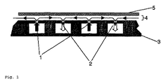
真空またはほぼ真空の条件下で使用するための浮上装置は、ガス用の複数の噴射点(1)および隣接する吸引点(2)を有する浮上プレート(3)を含み、空気ベアリング(4)を作り出して、それにより薄いプレート状基板(5)を支持する。さらに別の実施例は、支持された基板用の搬送機構、および/または浮上プレートを傾ける傾斜機構を含む。 A levitation device for use under vacuum or near-vacuum conditions includes a levitation plate (3) having a plurality of injection points (1) for gas and an adjacent suction point (2), and includes an air bearing (4). Create and thereby support a thin plate-like substrate (5). Yet another embodiment includes a transport mechanism for a supported substrate and / or a tilt mechanism that tilts the flying plate.
Description
発明の背景
この発明は一般に、真空プロセス装置における基板の移動に該当し、特に、LCD製造用に並行して採用される多数のプラズマ強化化学気相成長(PECVD)反応器に該当する。それはまた、半導体ウェーハ、光学ガラスおよび建築用ガラス、工具ビットといった任意の他の種類の基板の真空における移動のために採用されてもよく、また、エッチング、スパッタリング、蒸着、化学気相成長などといった多くの異なる真空プロセスにおいて採用されてもよい。
BACKGROUND OF THE INVENTION This invention generally relates to substrate movement in vacuum process equipment, and in particular to a number of plasma enhanced chemical vapor deposition (PECVD) reactors employed in parallel for LCD manufacturing. It may also be employed for moving in vacuum any other type of substrate such as semiconductor wafers, optical and architectural glass, tool bits, etc., and also such as etching, sputtering, vapor deposition, chemical vapor deposition, etc. It may be employed in many different vacuum processes.
多くの真空プロセス装置では、実際のプロセスチャンバ内で真空が一定に保たれるよう、基板はロードロックによってプロセスチャンバに装填される。 In many vacuum process equipment, the substrate is loaded into the process chamber by a load lock so that the vacuum is kept constant in the actual process chamber.
真空条件下で(半導体製造装置などにおいて)ロードロックから実際のプロセスチャンバへ基板を装入し、取出すために、今日では大抵、装填フォークと持上げピンとの組合せが使用されている。しかしながら、ピンの使用はピンの機械的信頼性に関連する問題を提示し、ピンはまた、蒸着中のプラズマの均一性を妨げる傾向がある。今日の基板サイズ(面積)はますます大きくなってきているため、および、基板はますます薄くなる(たとえば、0.5mmで2m2を上回るガラス基板)かまたは剛性がますます小さく(ポリマー基板、上昇したプロセス温度)なってきているため、そのような壊れやすい基板を搬送するピンおよび/またはフォークの有用性はますます制限される。さらに、そのような機械的装入および取出しシステムの使用は、最小限の真空プロセスシステムの高さ(反応器の高さなど)を必要とし、それはPECVD反応器の場合、特に望ましくない。なぜなら、PECVD反応器は、最小限の反応器間隙寸法(すなわち、頂部電極と反応器底部との距離)を要求し、それも蒸着速度といったプロセスパラメータウィンドウを制限するためである。一般に最小限の反応器高さを必要とすることにより、そのような機械的装入および取出しシステムはまた、そのような真空蒸着システムがいくつか並行して、および互いに重なって使用される場合に設置面積(全体的な高さ)を増大させる。機械的装入および取出し装置の使用も粒子供給源をしばしば取込み、そのため、そのように製造された製品における欠陥数を増大させる傾向にある。 Today, a combination of loading forks and lifting pins is often used to load and unload substrates from a load lock into an actual process chamber (such as in semiconductor manufacturing equipment) under vacuum conditions. However, the use of pins presents problems related to the mechanical reliability of the pins, and the pins also tend to hinder plasma uniformity during deposition. Because today's substrate sizes (areas) are getting larger and larger, and substrates are becoming increasingly thinner (for example, glass substrates that are larger than 2 m 2 at 0.5 mm) or less rigid (polymer substrates, Increasing process temperatures) are increasingly limiting the usefulness of pins and / or forks carrying such fragile substrates. Furthermore, the use of such a mechanical charging and unloading system requires a minimum vacuum process system height (such as reactor height), which is particularly undesirable in the case of PECVD reactors. This is because PECVD reactors require a minimum reactor gap size (ie, the distance between the top electrode and the reactor bottom), which also limits process parameter windows such as deposition rate. By generally requiring a minimum reactor height, such mechanical charging and unloading systems can also be used when several such vacuum deposition systems are used in parallel and overlapping each other. Increase the installation area (overall height). The use of mechanical charging and unloading equipment also often incorporates particle sources and therefore tends to increase the number of defects in products so manufactured.
関連技術
エアークッション運搬装置に載せてガラス基板を搬送することは、当該技術分野において公知である。US3,607,198は、大気条件下でプレート状基板を空気圧で支持するための装置を概説している。US6,220,056は、機械加工設備において薄い板ガラスを取扱うための装置であって、接触することなく板ガラスを収容するのに十分な間隔で互いに平行に配置された平坦な表面を有する少なくとも2枚のプレートを含む装置を提供している。これらの表面は多数のガス通路を示している。
Related Art It is well known in the art to transport a glass substrate on an air cushion transport device. US 3,607,198 outlines an apparatus for pneumatically supporting a plate-like substrate under atmospheric conditions. US Pat. No. 6,220,056 is an apparatus for handling thin glass sheets in a machining facility, having at least two flat surfaces arranged parallel to each other at a sufficient interval to accommodate the glass sheets without contact An apparatus including a plate of the same is provided. These surfaces represent a number of gas passages.
しかしながら、先行技術は、(ピン/フォーク解決策と同様)上述の問題すべてを同時に解決する解決策を述べてはおらず、および/または、それは、壊れやすい大型基板を真空条件下でどのようにして搬送するかについて教示していない。一般に、「真空条件」と「空気に載せた搬送」とは互いに矛盾するように思える。しかしながら、説明されるこの発明が示し得るように、先行技術に対する明らかな利点が達成され得る。 However, the prior art does not describe a solution that solves all of the above problems at the same time (similar to the pin / fork solution) and / or how it can handle fragile large substrates under vacuum conditions It does not teach how to transport. In general, “vacuum conditions” and “transport on air” seem to contradict each other. However, obvious advantages over the prior art can be achieved as the described invention can be shown.
発明の概要
真空またはほぼ真空の条件下で使用するための浮上装置は、ガス用の複数の噴射点および隣接する吸引点を有する浮上プレートを含み、空気ベアリングを作り出して、それにより薄いプレート状基板を支持する。有利には、吸引点および噴射点は交互に配置され、それぞれ接続されて浮上または吸引ネットワーク(11)を形成している。さらに別の実施例は、基板用搬送機構、および/または浮上プレートを傾ける傾斜機構を含む。
SUMMARY OF THE INVENTION A levitation device for use under vacuum or near-vacuum conditions includes a levitation plate having a plurality of injection points for gas and an adjacent suction point, creating an air bearing, thereby thin plate-like substrate Support. Advantageously, the suction points and injection points are arranged alternately and are connected to each other to form a levitation or suction network (11). Yet another embodiment includes a substrate transport mechanism and / or a tilt mechanism for tilting the floating plate.
発明の詳細な説明
この発明は、上述の問題、つまり、壊れやすい大型基板をロードロックチャンバと真空反応器との間でどのようにして確実に搬送するか、および反応器のサイズおよびそのプロセス均一性に対する影響をどのようにして最小限に抑えるかという問題を、真空条件下での搬送に均一な空気またはガスベアリング(浮上)を用いることによって克服する。密度が2700kg/m3、厚さが0.5〜3mmのガラス基板は、1平方センチメートル当たり0.135g〜0.81gの重量を有する。これは、13〜80パスカル(0.13〜0.8mbar)の圧力を表わす。このため、0.13〜0.8mbarの圧力がかかったガスは、そのような基板を持上げることができる。図1によれば、浮上ガスは、噴射点1を介して噴射され、さらに、より低い圧力で吸引点2を介して真空チャンバから吸い出される(噴射と吸引との圧力差は、浮上に必要な最小値よりも大きい)。このようにして基板5が空気ベアリング5上で支持される。噴射点1および吸引点2は浮上プレート3に配置され、それはロボットアームまたはプロセスチャンバ底部であり得る。
DETAILED DESCRIPTION OF THE INVENTION The present invention addresses the above-mentioned problems: how to reliably transport a fragile large substrate between a load lock chamber and a vacuum reactor, and the reactor size and process uniformity. The problem of how to minimize the effects on sex is overcome by using uniform air or gas bearings (levitation) for transport under vacuum conditions. A glass substrate having a density of 2700 kg / m 3 and a thickness of 0.5 to 3 mm has a weight of 0.135 g to 0.81 g per square centimeter. This represents a pressure of 13-80 Pascal (0.13-0.8 mbar). For this reason, a gas applied with a pressure of 0.13 to 0.8 mbar can lift such a substrate. According to FIG. 1, the levitation gas is injected through the injection point 1 and further drawn out of the vacuum chamber through the suction point 2 at a lower pressure (the pressure difference between injection and suction is necessary for levitation) Greater than the minimum value). In this way, the
基板の装入および取出しのための浮上中にロードロックおよび反応器において十分に高い真空を保つために、浮上による基板搬送に必要なガスの大部分は、慎重に配置された吸引点を通って容易に排出され、残りの浮上ガスはすべて、実際の真空プロセス(蒸着またはエッチングなど)が起こる前にシステムから容易に除去される。ガスは主として吸引点を通って排出され、基板の縁でのガス漏れは制限されている。固定真空プロセスの場合、ガス噴射、ひいては浮上を停止することが可能である。真空プロセス中に継続移動する場合、たとえば、基板が最初または最後に円筒ロールへ、もしくは円筒ロールから転がされるインラインプロセスなどでは、不活性ガスが使用可能である。したがって、および従来の知識に反して、壊れやすい大型基板のガスクッション搬送が真空システムにおいて達成され得る。 In order to maintain a sufficiently high vacuum in the load lock and reactor during ascent for substrate loading and unloading, most of the gas required for substrate transport by levitation passes through carefully positioned suction points. Easily vented and any remaining flying gas is easily removed from the system before the actual vacuum process (such as deposition or etching) occurs. The gas is mainly exhausted through the suction point, and gas leakage at the edge of the substrate is limited. In the case of a fixed vacuum process, it is possible to stop the gas injection and thus the levitation. In the case of continuous movement during the vacuum process, for example in an in-line process where the substrate is first or last rolled to or from the cylindrical roll, an inert gas can be used. Thus, and contrary to conventional knowledge, gas cushion transfer of fragile large substrates can be achieved in a vacuum system.
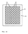
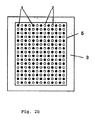
図2aおよび図2bは、浮上プレート3における吸引点2および噴射点1の2つの可能な配置を示している。周囲の線は、基板5の可能な位置を示している。
FIGS. 2 a and 2 b show two possible arrangements of suction point 2 and injection point 1 on the
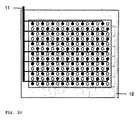
図2cは、全体的な均一性が得られるよう噴射点および吸引点を交互に配置することによるこの発明の好ましい一実施例を示している。したがって、基板側での高速ガス流が回避され、その結果、望ましくない粒子の移動を引き起こす乱気流も回避される。噴射孔および吸引孔のサイズと間隔、噴射および吸引圧力、ならびに浮上ガスの性質は変化し、基板材料および基板の厚さに非常に依存する。好ましくは、吸引孔は接続されて真空(吸引)ネットワーク12を確立し、噴射孔は接続されて浮上ガスネットワーク12を確立する。
FIG. 2c shows a preferred embodiment of the invention by alternating the injection and suction points so that overall uniformity is obtained. Thus, high-speed gas flow on the substrate side is avoided, and as a result, turbulence that causes undesirable particle movement is also avoided. The size and spacing of the injection and suction holes, the injection and suction pressure, and the nature of the flying gas vary and are highly dependent on the substrate material and the substrate thickness. Preferably, the suction holes are connected to establish a vacuum (suction)
例1:密度が2700kg/m3、厚さが0.5mmのガラス基板が、装入/取出し動作のために窒素の噴射によって浮上し、窒素は、噴射溝では100Pa、基板下では50Pa、吸引溝では20Paの圧力を有する。 Example 1: A glass substrate having a density of 2700 kg / m 3 and a thickness of 0.5 mm is floated by jetting nitrogen for loading / unloading operation. Nitrogen is sucked by 100 Pa in the jet groove and sucked by 50 Pa under the substrate. The groove has a pressure of 20 Pa.
吸引カップは真空では使用できないため、図3aおよび図3bは、クランプシステム2
2(グリッパ)を有するロボットテーブル24を有するロボットを示しており、それは、好ましい一実施例では、上述のガスクッションによって基板5が一旦浮上すると基板5をたとえばプロセスチャンバ(プロセスチャンバ底部21)の中および外へ移動させるために使用される。基板5が浮上するため、また、装入および取出し移動が実質的に水平の平面で行なわれるため、基板の慣性に打勝ち、ひいてはそれをその最終的な装入および取出し位置へ移動させるのに、ほんの少量の力しか必要とされない。また、これに代えて、基板が十分に厚く硬い場合には、基板を縁から押すことも可能である(図3b、プッシュ/プルシステム23)。
Since the suction cup cannot be used in a vacuum, FIGS. 3a and 3b show the clamping system 2
1 shows a robot having a robot table 24 with 2 (grippers), which in one preferred embodiment, once the
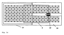
図3cおよび図3dは各々この発明の一実施例を示しており、真空プロセスチャンバ自体(左)、および搬送ロボットアセンブリに属するテーブル(ロボットテーブル24)(右)の双方には、上述のような真空での浮上用の噴射および吸引手段が備わっている。ロボットが一旦、次に開かれるプロセスチャンバの前のその装入および取出し位置へ移動すると、基板は浮上し、次にグリッパ(クランプシステム22)またはプッシュプルシステム23によって反応器の中および外へ摺動される。一実施例では、このグリッパは溝に収容され、溝は空気ベアリングテーブルの双方に機械加工されて、円滑、均一、真っ直ぐで実質的に水平の装入および取出し移動を可能にする。
FIGS. 3c and 3d each show one embodiment of the present invention. Both the vacuum process chamber itself (left) and the table belonging to the transfer robot assembly (robot table 24) (right) are as described above. There are jetting and suction means for levitation in vacuum. Once the robot has moved to its loading and unloading position in front of the next opened process chamber, the substrate is then lifted and then slid into and out of the reactor by the gripper (clamp system 22) or push-
図3a〜図3dのすべての部分が真空下にあるよう、図1〜図3に示す要素がすべて、大型容器または真空受け部(図示せず)によって封入されていることが強調される。この大型容器はロードロック(同様に図示せず)に通じていてもよく、または複数のプロセスチャンバを含んでいてもよい。 It is emphasized that all the elements shown in FIGS. 1 to 3 are enclosed by a large container or a vacuum receptacle (not shown) so that all parts of FIGS. 3a to 3d are under vacuum. The large container may lead to a load lock (also not shown) or may include multiple process chambers.
他の実施例では、クランプシステムは基板移動に平行な基板側でも採用されてもよく、ロール、磁石および静電気装置による移動手段でさえも、ガスによって基板が一旦浮上すると基板を進めるために配置されてもよい。 In other embodiments, the clamping system may be employed on the side of the substrate parallel to the substrate movement, and even moving means such as rolls, magnets and electrostatic devices are arranged to advance the substrate once it has been lifted by the gas. May be.
この発明の一実施例では、基板移動が重力によって支持または誘発され、その結果基板が平らに保たれるように、ロボットテーブルおよびプロセスチャンバは、各々またはともに、装入および取出し動作中に傾斜機構によって若干傾けられてもよい。 In one embodiment of the present invention, the robot table and process chamber, either or both, can be tilted during loading and unloading operations so that substrate movement is supported or triggered by gravity, so that the substrate is kept flat. May be slightly tilted.
反応器に基板が一旦装入されると、または取出されると、移送ロボットアセンブリは、ロードロックチャンバ、さらに別の反応器チャンバ、または数々のそのようなチャンバのために働くよう、複数の方向および軸において移動してもよい。 Once the substrate has been loaded into or removed from the reactor, the transfer robot assembly can operate in multiple directions to work for the load lock chamber, yet another reactor chamber, or a number of such chambers. And may move in the axis.
発明のさらに別の利点
真空反応器における可動部品をすべて排除することにより、高度の信頼性が得られる。機械の故障は回避され、腐食し得る、または粒子供給源となり得る部品は存在しない。持上げピンを排除することにより、高さが低く、ひいては間隙がより小さく、堆積速度がより速い、より小さな反応器が構築され得る。反応器高さが低減するため、より多くのそのような反応器を互いの上に重ね、並行して使用することができ、それは全体的なシステム生産性を高める。浮上した基板にかかる力はほとんどないため、損傷(たとえばガラス基板の破損)はより起こりにくくなる。反応器の底部の噴射孔および吸引孔はピン用の孔よりもかなり小さく作ることができるため、はるかにより均一なプラズマが得られ得る。ピンがないため、製造されたLCDディスプレイの活性領域をピンが妨げることはない。これにより、単一の大型基板から作られるディスプレイサイズをピン配置とは無関係に任意に規定することができる。さらに、このシステムは「真空掃除機」という全体的効果を有する。すなわち、浮上用に導入されるガスを容易に除去することにより、装入/取出プロセスとは無関係に存在したかもしれない望ましくない粒子が吸引システムを通って除去される。
Yet another advantage of the invention A high degree of reliability is obtained by eliminating all moving parts in the vacuum reactor. Machine failures are avoided and there are no parts that can corrode or become a source of particles. By eliminating the lifting pins, smaller reactors can be constructed that are lower in height and thus have smaller gaps and faster deposition rates. Because the reactor height is reduced, more such reactors can be stacked on top of each other and used in parallel, which increases overall system productivity. Since there is almost no force applied to the floating substrate, damage (for example, breakage of the glass substrate) is less likely to occur. Since the injection and suction holes at the bottom of the reactor can be made much smaller than the holes for the pins, a much more uniform plasma can be obtained. Because there are no pins, the pins do not interfere with the active area of the manufactured LCD display. Thereby, the display size made from a single large substrate can be arbitrarily defined irrespective of the pin arrangement. Furthermore, this system has the overall effect of a “vacuum cleaner”. That is, by easily removing the gas introduced for levitation, unwanted particles that may have existed independently of the loading / unloading process are removed through the suction system.
1 噴射点、2 吸引点、3 浮上プレート(ロボットアームまたはプロセスチャンバ底部)、4 空気ベアリング、5 基板、11 浮上ガスネットワーク、12 真空(吸引)ネットワーク、21 プロセスチャンバ底部、22 クランプシステム、23 プッシュ/プルシステム、24 ロボットテーブル。 1 injection point, 2 suction point, 3 floating plate (bottom of robot arm or process chamber), 4 air bearing, 5 substrate, 11 floating gas network, 12 vacuum (suction) network, 21 process chamber bottom, 22 clamp system, 23 push / Pull system, 24 robot table.
Claims (10)
Applications Claiming Priority (2)
| Application Number | Priority Date | Filing Date | Title |
|---|---|---|---|
| US58664504P | 2004-07-09 | 2004-07-09 | |
| PCT/CH2005/000392 WO2006005214A1 (en) | 2004-07-09 | 2005-07-07 | Gas bearing substrate-loading mechanism process |
Publications (2)
| Publication Number | Publication Date |
|---|---|
| JP2008505041A true JP2008505041A (en) | 2008-02-21 |
| JP2008505041A5 JP2008505041A5 (en) | 2008-08-07 |
Family
ID=34971820
Family Applications (1)
| Application Number | Title | Priority Date | Filing Date |
|---|---|---|---|
| JP2007519595A Withdrawn JP2008505041A (en) | 2004-07-09 | 2005-07-07 | Gas bearing substrate loading mechanism |
Country Status (9)
| Country | Link |
|---|---|
| US (1) | US20070215437A1 (en) |
| EP (1) | EP1768921A1 (en) |
| JP (1) | JP2008505041A (en) |
| KR (1) | KR20070037741A (en) |
| CN (1) | CN101023011A (en) |
| AU (1) | AU2005262191A1 (en) |
| IL (1) | IL180080A0 (en) |
| TW (1) | TW200624357A (en) |
| WO (1) | WO2006005214A1 (en) |
Cited By (11)
| Publication number | Priority date | Publication date | Assignee | Title |
|---|---|---|---|---|
| JP2010143733A (en) * | 2008-12-19 | 2010-07-01 | Sumitomo Heavy Ind Ltd | Substrate handling system and substrate handling method |
| JP2010159164A (en) * | 2008-12-12 | 2010-07-22 | Tokyo Electron Ltd | Vacuum processing device, vacuum processing system and processing method |
| WO2011002155A2 (en) * | 2009-06-29 | 2011-01-06 | 주식회사 공영 | Flat plate precision floating system |
| US8026907B2 (en) | 2006-02-28 | 2011-09-27 | Panasonic Corporation | Plasma display device |
| JP2011219250A (en) * | 2010-04-14 | 2011-11-04 | Oiles Corp | Non-contact carrying device |
| JP2011235999A (en) * | 2010-05-10 | 2011-11-24 | Oiles Corp | Non-contact conveying device |
| WO2013190800A1 (en) * | 2012-06-21 | 2013-12-27 | 川崎重工業株式会社 | Substrate transport system |
| JP2014133655A (en) * | 2014-03-17 | 2014-07-24 | Oiles Ind Co Ltd | Non-contact conveyance apparatus |
| JP2014210664A (en) * | 2013-04-17 | 2014-11-13 | サムソン エレクトロ−メカニックス カンパニーリミテッド.Samsung Electro−Mechanics Co.,Ltd. | Non-contact substrate transfer turner |
| WO2015178189A1 (en) * | 2014-05-20 | 2015-11-26 | オイレス工業株式会社 | Conveyance rail and flotation conveying device |
| KR20190055133A (en) * | 2016-09-13 | 2019-05-22 | 코닝 인코포레이티드 | Glass-based processing apparatus and method |
Families Citing this family (21)
| Publication number | Priority date | Publication date | Assignee | Title |
|---|---|---|---|---|
| US20090291209A1 (en) | 2008-05-20 | 2009-11-26 | Asm International N.V. | Apparatus and method for high-throughput atomic layer deposition |
| US9238867B2 (en) * | 2008-05-20 | 2016-01-19 | Asm International N.V. | Apparatus and method for high-throughput atomic layer deposition |
| WO2009155119A2 (en) * | 2008-05-30 | 2009-12-23 | Alta Devices, Inc. | Methods and apparatus for a chemical vapor deposition reactor |
| KR100876337B1 (en) * | 2008-06-25 | 2008-12-29 | 이재성 | Noncontact conveying plate having a suction |
| KR101293289B1 (en) * | 2010-06-04 | 2013-08-09 | 김영태 | Noncontact feed apparatus using vacuum pad |
| CN102020115B (en) * | 2010-11-26 | 2013-01-30 | 认知精密制造(苏州)有限公司 | Air rise type carrier for loading and moving liquid crystal display (LCD) chassis |
| DE102012219332B4 (en) * | 2012-10-23 | 2014-11-13 | Mdi Schott Advanced Processing Gmbh | Device and method for storing and fixing a glass pane |
| KR101978147B1 (en) | 2012-11-15 | 2019-05-15 | (주)아모레퍼시픽 | Perfume composition for expressing the fragrance of Rubus coreanus Miquel |
| US9499908B2 (en) | 2015-02-13 | 2016-11-22 | Eastman Kodak Company | Atomic layer deposition apparatus |
| US9506147B2 (en) | 2015-02-13 | 2016-11-29 | Eastman Kodak Company | Atomic-layer deposition apparatus using compound gas jet |
| US9499906B2 (en) | 2015-02-13 | 2016-11-22 | Eastman Kodak Company | Coating substrate using bernoulli atomic-layer deposition |
| US9528184B2 (en) | 2015-02-13 | 2016-12-27 | Eastman Kodak Company | Atomic-layer deposition method using compound gas jet |
| KR102298805B1 (en) | 2015-03-05 | 2021-09-08 | (주)아모레퍼시픽 | Perfume composition for reproducibly expressing the fragrance of Osmanthus asiaticus. |
| CN104659039B (en) * | 2015-03-13 | 2017-10-27 | 京东方科技集团股份有限公司 | Bearing substrate, flexible display apparatus preparation method |
| KR102610348B1 (en) | 2015-10-30 | 2023-12-06 | (주)아모레퍼시픽 | Perfume composition for reproducibly expressing the fragrance of Magnolia sieboldii K. Koch |
| KR20170138834A (en) * | 2016-06-08 | 2017-12-18 | 코닝 인코포레이티드 | Apparatus for laminating |
| US9889995B1 (en) * | 2017-03-15 | 2018-02-13 | Core Flow Ltd. | Noncontact support platform with blockage detection |
| CN107655788B (en) * | 2017-11-16 | 2019-10-01 | 合肥工业大学 | It is a kind of for measuring the device of glass substrate air-flotation system choke block Restriction Parameters |
| CN110498233B (en) * | 2019-07-26 | 2021-04-27 | 江苏科技大学 | Two-dimensional non-contact conveying platform device |
| KR102578464B1 (en) * | 2020-06-10 | 2023-09-14 | 세메스 주식회사 | Substrate transfer module and die bonding apparatus including the same |
| CN114538111B (en) * | 2022-03-21 | 2024-03-08 | 江苏威尔赛科技有限公司 | Garbage bedding and clothing recovery system with automatic disinfection function |
Family Cites Families (19)
| Publication number | Priority date | Publication date | Assignee | Title |
|---|---|---|---|---|
| US2080083A (en) * | 1934-06-08 | 1937-05-11 | Assurex Le Roi Des Verres De S | Manufacture of hardened or tempered glass plates |
| US2905768A (en) * | 1954-09-24 | 1959-09-22 | Ibm | Air head |
| NL137693C (en) * | 1964-03-25 | |||
| GB1137555A (en) * | 1965-10-22 | 1968-12-27 | Pilkington Brothers Ltd | Improvements in or relating to the transporting of sheet materials |
| US3455669A (en) * | 1966-05-09 | 1969-07-15 | Permaglass | Apparatus for heat treating glass on a fluid support |
| FR1527937A (en) * | 1967-03-31 | 1968-06-07 | Saint Gobain | Device for transporting a sheet-shaped material on a gas cushion |
| US3517958A (en) * | 1968-06-17 | 1970-06-30 | Ibm | Vacuum pick-up with air shield |
| US4014576A (en) * | 1975-06-19 | 1977-03-29 | International Business Machines Corporation | Article carrier |
| US4521268A (en) * | 1981-08-26 | 1985-06-04 | Edward Bok | Apparatus for deposition of fluid and gaseous media on substrates |
| US4773687A (en) * | 1987-05-22 | 1988-09-27 | American Telephone And Telegraph Company, At&T Technologies, Inc. | Wafer handler |
| JP2865690B2 (en) * | 1989-02-17 | 1999-03-08 | 株式会社日立製作所 | Mating insertion device |
| JPH0818678B2 (en) * | 1989-09-05 | 1996-02-28 | 日本板硝子株式会社 | Air bed carrier |
| JP3128709B2 (en) * | 1992-08-04 | 2001-01-29 | 株式会社新川 | Non-contact moving table |
| US5634636A (en) * | 1996-01-11 | 1997-06-03 | Xerox Corporation | Flexible object handling system using feedback controlled air jets |
| DE19649488A1 (en) * | 1996-11-29 | 1997-11-06 | Schott Glaswerke | Pneumatic handling or transport system and for thin glass sheet in display manufacture |
| JP4354039B2 (en) * | 1999-04-02 | 2009-10-28 | 東京エレクトロン株式会社 | Drive device |
| US6491435B1 (en) * | 2000-07-24 | 2002-12-10 | Moore Epitaxial, Inc. | Linear robot |
| DE10148038A1 (en) * | 2001-09-28 | 2003-04-17 | Grenzebach Maschb Gmbh | Device for transferring plates from a plate conveyor to a stacking frame or the like |
| TWI222423B (en) * | 2001-12-27 | 2004-10-21 | Orbotech Ltd | System and methods for conveying and transporting levitated articles |
-
2005
- 2005-07-07 EP EP05756159A patent/EP1768921A1/en not_active Withdrawn
- 2005-07-07 US US11/571,604 patent/US20070215437A1/en not_active Abandoned
- 2005-07-07 CN CNA2005800232489A patent/CN101023011A/en active Pending
- 2005-07-07 WO PCT/CH2005/000392 patent/WO2006005214A1/en active Application Filing
- 2005-07-07 AU AU2005262191A patent/AU2005262191A1/en not_active Abandoned
- 2005-07-07 KR KR1020077000087A patent/KR20070037741A/en not_active Application Discontinuation
- 2005-07-07 JP JP2007519595A patent/JP2008505041A/en not_active Withdrawn
- 2005-07-08 TW TW094123153A patent/TW200624357A/en unknown
-
2006
- 2006-12-14 IL IL180080A patent/IL180080A0/en unknown
Cited By (15)
| Publication number | Priority date | Publication date | Assignee | Title |
|---|---|---|---|---|
| US8026907B2 (en) | 2006-02-28 | 2011-09-27 | Panasonic Corporation | Plasma display device |
| JP2010159164A (en) * | 2008-12-12 | 2010-07-22 | Tokyo Electron Ltd | Vacuum processing device, vacuum processing system and processing method |
| JP2010143733A (en) * | 2008-12-19 | 2010-07-01 | Sumitomo Heavy Ind Ltd | Substrate handling system and substrate handling method |
| KR101142959B1 (en) | 2009-06-29 | 2012-05-08 | 김영태 | Precision plate flotation system |
| WO2011002155A2 (en) * | 2009-06-29 | 2011-01-06 | 주식회사 공영 | Flat plate precision floating system |
| WO2011002155A3 (en) * | 2009-06-29 | 2011-03-24 | 주식회사 공영 | Flat plate precision floating system |
| JP2011219250A (en) * | 2010-04-14 | 2011-11-04 | Oiles Corp | Non-contact carrying device |
| JP2011235999A (en) * | 2010-05-10 | 2011-11-24 | Oiles Corp | Non-contact conveying device |
| WO2013190800A1 (en) * | 2012-06-21 | 2013-12-27 | 川崎重工業株式会社 | Substrate transport system |
| JP2014007193A (en) * | 2012-06-21 | 2014-01-16 | Kawasaki Heavy Ind Ltd | Substrate transfer system |
| JP2014210664A (en) * | 2013-04-17 | 2014-11-13 | サムソン エレクトロ−メカニックス カンパニーリミテッド.Samsung Electro−Mechanics Co.,Ltd. | Non-contact substrate transfer turner |
| JP2014133655A (en) * | 2014-03-17 | 2014-07-24 | Oiles Ind Co Ltd | Non-contact conveyance apparatus |
| WO2015178189A1 (en) * | 2014-05-20 | 2015-11-26 | オイレス工業株式会社 | Conveyance rail and flotation conveying device |
| KR20190055133A (en) * | 2016-09-13 | 2019-05-22 | 코닝 인코포레이티드 | Glass-based processing apparatus and method |
| KR102450782B1 (en) | 2016-09-13 | 2022-10-06 | 코닝 인코포레이티드 | Glass substrate processing apparatus and method |
Also Published As
| Publication number | Publication date |
|---|---|
| TW200624357A (en) | 2006-07-16 |
| US20070215437A1 (en) | 2007-09-20 |
| IL180080A0 (en) | 2007-05-15 |
| EP1768921A1 (en) | 2007-04-04 |
| AU2005262191A1 (en) | 2006-01-19 |
| CN101023011A (en) | 2007-08-22 |
| WO2006005214A1 (en) | 2006-01-19 |
| KR20070037741A (en) | 2007-04-06 |
Similar Documents
| Publication | Publication Date | Title |
|---|---|---|
| JP2008505041A (en) | Gas bearing substrate loading mechanism | |
| CN101443899B (en) | Substrate conveyance device and vertical heat treatment equipment | |
| KR100310249B1 (en) | Substrate Processing Equipment | |
| KR101088289B1 (en) | Loading table, processing apparatus and processing system | |
| JP5548163B2 (en) | Substrate transport mechanism, substrate processing apparatus, and semiconductor device manufacturing method | |
| US20080025835A1 (en) | Bernoulli wand | |
| WO2003100848A1 (en) | Substrate processing device and substrate processing method | |
| JP6336231B1 (en) | Vacuum processing equipment | |
| JP2013086241A (en) | Chuck device and chuck method | |
| KR20180035664A (en) | Substrate transporter and substrate transport method | |
| JP2020526040A (en) | Apparatus for transporting a substrate, processing apparatus having a receiving plate adapted to a substrate carrier of such apparatus, and method for processing a substrate using the apparatus for transporting the substrate, and processing system | |
| JP4274601B2 (en) | Substrate transfer device and operation method thereof | |
| KR20130087604A (en) | Deposition apparatus | |
| US10199250B2 (en) | Substrate processing device | |
| JP5399153B2 (en) | Vacuum processing apparatus, vacuum processing system and processing method | |
| JP2011086795A (en) | Substrate conveying apparatus and vacuum processing system with the substrate conveying apparatus | |
| JP2000177842A (en) | Carrying device and vacuum processing device | |
| JP4108242B2 (en) | Transport device | |
| KR20190002415A (en) | Apparatus for processing a substrate, a processing system for processing a substrate, and a method for servicing an apparatus for processing a substrate | |
| KR102444830B1 (en) | Methods for handling masks in a vacuum system and vacuum system | |
| CN219190236U (en) | Mechanical arm | |
| JP4746167B2 (en) | Board loading / unloading method | |
| JP5145209B2 (en) | Vacuum processing equipment | |
| JPH04242954A (en) | Wafer chuck | |
| JP2005187114A (en) | Vacuum treatment device |
Legal Events
| Date | Code | Title | Description |
|---|---|---|---|
| A521 | Request for written amendment filed |
Free format text: JAPANESE INTERMEDIATE CODE: A523 Effective date: 20080619 |
|
| A621 | Written request for application examination |
Free format text: JAPANESE INTERMEDIATE CODE: A621 Effective date: 20080619 |
|
| A761 | Written withdrawal of application |
Free format text: JAPANESE INTERMEDIATE CODE: A761 Effective date: 20100331 |