JP2010141990A - 電力変換装置 - Google Patents
電力変換装置 Download PDFInfo
- Publication number
- JP2010141990A JP2010141990A JP2008314276A JP2008314276A JP2010141990A JP 2010141990 A JP2010141990 A JP 2010141990A JP 2008314276 A JP2008314276 A JP 2008314276A JP 2008314276 A JP2008314276 A JP 2008314276A JP 2010141990 A JP2010141990 A JP 2010141990A
- Authority
- JP
- Japan
- Prior art keywords
- circuit
- power conversion
- power
- voltage
- semiconductor switch
- Prior art date
- Legal status (The legal status is an assumption and is not a legal conclusion. Google has not performed a legal analysis and makes no representation as to the accuracy of the status listed.)
- Granted
Links
Images
Classifications
-
- H—ELECTRICITY
- H02—GENERATION; CONVERSION OR DISTRIBUTION OF ELECTRIC POWER
- H02M—APPARATUS FOR CONVERSION BETWEEN AC AND AC, BETWEEN AC AND DC, OR BETWEEN DC AND DC, AND FOR USE WITH MAINS OR SIMILAR POWER SUPPLY SYSTEMS; CONVERSION OF DC OR AC INPUT POWER INTO SURGE OUTPUT POWER; CONTROL OR REGULATION THEREOF
- H02M1/00—Details of apparatus for conversion
- H02M1/32—Means for protecting converters other than automatic disconnection
-
- B—PERFORMING OPERATIONS; TRANSPORTING
- B60—VEHICLES IN GENERAL
- B60L—PROPULSION OF ELECTRICALLY-PROPELLED VEHICLES; SUPPLYING ELECTRIC POWER FOR AUXILIARY EQUIPMENT OF ELECTRICALLY-PROPELLED VEHICLES; ELECTRODYNAMIC BRAKE SYSTEMS FOR VEHICLES IN GENERAL; MAGNETIC SUSPENSION OR LEVITATION FOR VEHICLES; MONITORING OPERATING VARIABLES OF ELECTRICALLY-PROPELLED VEHICLES; ELECTRIC SAFETY DEVICES FOR ELECTRICALLY-PROPELLED VEHICLES
- B60L3/00—Electric devices on electrically-propelled vehicles for safety purposes; Monitoring operating variables, e.g. speed, deceleration or energy consumption
- B60L3/0023—Detecting, eliminating, remedying or compensating for drive train abnormalities, e.g. failures within the drive train
- B60L3/003—Detecting, eliminating, remedying or compensating for drive train abnormalities, e.g. failures within the drive train relating to inverters
-
- H—ELECTRICITY
- H02—GENERATION; CONVERSION OR DISTRIBUTION OF ELECTRIC POWER
- H02M—APPARATUS FOR CONVERSION BETWEEN AC AND AC, BETWEEN AC AND DC, OR BETWEEN DC AND DC, AND FOR USE WITH MAINS OR SIMILAR POWER SUPPLY SYSTEMS; CONVERSION OF DC OR AC INPUT POWER INTO SURGE OUTPUT POWER; CONTROL OR REGULATION THEREOF
- H02M7/00—Conversion of AC power input into DC power output; Conversion of DC power input into AC power output
- H02M7/42—Conversion of DC power input into AC power output without possibility of reversal
- H02M7/44—Conversion of DC power input into AC power output without possibility of reversal by static converters
- H02M7/48—Conversion of DC power input into AC power output without possibility of reversal by static converters using discharge tubes with control electrode or semiconductor devices with control electrode
- H02M7/53—Conversion of DC power input into AC power output without possibility of reversal by static converters using discharge tubes with control electrode or semiconductor devices with control electrode using devices of a triode or transistor type requiring continuous application of a control signal
- H02M7/537—Conversion of DC power input into AC power output without possibility of reversal by static converters using discharge tubes with control electrode or semiconductor devices with control electrode using devices of a triode or transistor type requiring continuous application of a control signal using semiconductor devices only, e.g. single switched pulse inverters
- H02M7/5387—Conversion of DC power input into AC power output without possibility of reversal by static converters using discharge tubes with control electrode or semiconductor devices with control electrode using devices of a triode or transistor type requiring continuous application of a control signal using semiconductor devices only, e.g. single switched pulse inverters in a bridge configuration
- H02M7/53871—Conversion of DC power input into AC power output without possibility of reversal by static converters using discharge tubes with control electrode or semiconductor devices with control electrode using devices of a triode or transistor type requiring continuous application of a control signal using semiconductor devices only, e.g. single switched pulse inverters in a bridge configuration with automatic control of output voltage or current
- H02M7/53875—Conversion of DC power input into AC power output without possibility of reversal by static converters using discharge tubes with control electrode or semiconductor devices with control electrode using devices of a triode or transistor type requiring continuous application of a control signal using semiconductor devices only, e.g. single switched pulse inverters in a bridge configuration with automatic control of output voltage or current with analogue control of three-phase output
-
- H—ELECTRICITY
- H02—GENERATION; CONVERSION OR DISTRIBUTION OF ELECTRIC POWER
- H02P—CONTROL OR REGULATION OF ELECTRIC MOTORS, ELECTRIC GENERATORS OR DYNAMO-ELECTRIC CONVERTERS; CONTROLLING TRANSFORMERS, REACTORS OR CHOKE COILS
- H02P27/00—Arrangements or methods for the control of AC motors characterised by the kind of supply voltage
- H02P27/04—Arrangements or methods for the control of AC motors characterised by the kind of supply voltage using variable-frequency supply voltage, e.g. inverter or converter supply voltage
- H02P27/06—Arrangements or methods for the control of AC motors characterised by the kind of supply voltage using variable-frequency supply voltage, e.g. inverter or converter supply voltage using DC to AC converters or inverters
-
- H—ELECTRICITY
- H02—GENERATION; CONVERSION OR DISTRIBUTION OF ELECTRIC POWER
- H02P—CONTROL OR REGULATION OF ELECTRIC MOTORS, ELECTRIC GENERATORS OR DYNAMO-ELECTRIC CONVERTERS; CONTROLLING TRANSFORMERS, REACTORS OR CHOKE COILS
- H02P29/00—Arrangements for regulating or controlling electric motors, appropriate for both AC and DC motors
- H02P29/02—Providing protection against overload without automatic interruption of supply
- H02P29/024—Detecting a fault condition, e.g. short circuit, locked rotor, open circuit or loss of load
- H02P29/027—Detecting a fault condition, e.g. short circuit, locked rotor, open circuit or loss of load the fault being an over-current
-
- B—PERFORMING OPERATIONS; TRANSPORTING
- B60—VEHICLES IN GENERAL
- B60L—PROPULSION OF ELECTRICALLY-PROPELLED VEHICLES; SUPPLYING ELECTRIC POWER FOR AUXILIARY EQUIPMENT OF ELECTRICALLY-PROPELLED VEHICLES; ELECTRODYNAMIC BRAKE SYSTEMS FOR VEHICLES IN GENERAL; MAGNETIC SUSPENSION OR LEVITATION FOR VEHICLES; MONITORING OPERATING VARIABLES OF ELECTRICALLY-PROPELLED VEHICLES; ELECTRIC SAFETY DEVICES FOR ELECTRICALLY-PROPELLED VEHICLES
- B60L2210/00—Converter types
- B60L2210/40—DC to AC converters
- B60L2210/42—Voltage source inverters
-
- H—ELECTRICITY
- H02—GENERATION; CONVERSION OR DISTRIBUTION OF ELECTRIC POWER
- H02H—EMERGENCY PROTECTIVE CIRCUIT ARRANGEMENTS
- H02H7/00—Emergency protective circuit arrangements specially adapted for specific types of electric machines or apparatus or for sectionalised protection of cable or line systems, and effecting automatic switching in the event of an undesired change from normal working conditions
- H02H7/08—Emergency protective circuit arrangements specially adapted for specific types of electric machines or apparatus or for sectionalised protection of cable or line systems, and effecting automatic switching in the event of an undesired change from normal working conditions for dynamo-electric motors
- H02H7/0833—Emergency protective circuit arrangements specially adapted for specific types of electric machines or apparatus or for sectionalised protection of cable or line systems, and effecting automatic switching in the event of an undesired change from normal working conditions for dynamo-electric motors for electric motors with control arrangements
- H02H7/0838—Emergency protective circuit arrangements specially adapted for specific types of electric machines or apparatus or for sectionalised protection of cable or line systems, and effecting automatic switching in the event of an undesired change from normal working conditions for dynamo-electric motors for electric motors with control arrangements with H-bridge circuit
-
- H—ELECTRICITY
- H02—GENERATION; CONVERSION OR DISTRIBUTION OF ELECTRIC POWER
- H02J—ELECTRIC POWER NETWORKS; CIRCUIT ARRANGEMENTS OR SYSTEMS FOR SUPPLYING OR DISTRIBUTING ELECTRIC POWER; SYSTEMS FOR STORING ELECTRIC ENERGY
- H02J7/00—Circuit arrangements for charging or discharging batteries or for supplying loads from batteries
- H02J7/14—Circuit arrangements for charging or discharging batteries or for supplying loads from batteries for charging batteries from dynamo-electric generators driven at varying speed, e.g. on vehicle
-
- Y—GENERAL TAGGING OF NEW TECHNOLOGICAL DEVELOPMENTS; GENERAL TAGGING OF CROSS-SECTIONAL TECHNOLOGIES SPANNING OVER SEVERAL SECTIONS OF THE IPC; TECHNICAL SUBJECTS COVERED BY FORMER USPC CROSS-REFERENCE ART COLLECTIONS [XRACs] AND DIGESTS
- Y02—TECHNOLOGIES OR APPLICATIONS FOR MITIGATION OR ADAPTATION AGAINST CLIMATE CHANGE
- Y02T—CLIMATE CHANGE MITIGATION TECHNOLOGIES RELATED TO TRANSPORTATION
- Y02T10/00—Road transport of goods or passengers
- Y02T10/60—Other road transportation technologies with climate change mitigation effect
- Y02T10/64—Electric machine technologies in electromobility
-
- Y—GENERAL TAGGING OF NEW TECHNOLOGICAL DEVELOPMENTS; GENERAL TAGGING OF CROSS-SECTIONAL TECHNOLOGIES SPANNING OVER SEVERAL SECTIONS OF THE IPC; TECHNICAL SUBJECTS COVERED BY FORMER USPC CROSS-REFERENCE ART COLLECTIONS [XRACs] AND DIGESTS
- Y02—TECHNOLOGIES OR APPLICATIONS FOR MITIGATION OR ADAPTATION AGAINST CLIMATE CHANGE
- Y02T—CLIMATE CHANGE MITIGATION TECHNOLOGIES RELATED TO TRANSPORTATION
- Y02T10/00—Road transport of goods or passengers
- Y02T10/60—Other road transportation technologies with climate change mitigation effect
- Y02T10/72—Electric energy management in electromobility
Landscapes
- Engineering & Computer Science (AREA)
- Power Engineering (AREA)
- Life Sciences & Earth Sciences (AREA)
- Sustainable Development (AREA)
- Sustainable Energy (AREA)
- Transportation (AREA)
- Mechanical Engineering (AREA)
- Inverter Devices (AREA)
- Control Of Ac Motors In General (AREA)
- Rectifiers (AREA)
Abstract
【解決手段】第1の主端子と第2の主端子と制御端子とを有する半導体スイッチ6で構成された3相ブリッジ型の電力変換回路2と、半導体スイッチ6の動作を制御する制御回路3と、電力変換回路2の直流端子間の電圧を監視する電圧検出回路4とを備えた電力変換装置1であって、制御回路3は、電圧検出回路4によって検出された電力変換回路1の直流端子間の電圧が所定値より小さい状態が所定時間以上継続した場合に、半導体スイッチを遮断する保護機能を備える。
【選択図】図1
Description
このような従来の電力変換装置は、短絡故障が発生していない正常時にもシャント抵抗にて電力損失が発生する。このため、電力変換装置における効率が低下する。また、電力損失による過熱を防止するために放熱対策の必要性が生じる。この結果、電力変換装置の大型化・コストアップに繋がる。また、短絡故障によって流れた短絡電流を検出した後に、その大電流を半導体スイッチで遮断する必要がある。このため、大電流の遮断時に、半導体スイッチの安全動作領域を逸脱して2次的な故障が発生する可能性がある。
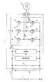
図1は、本発明の実施の形態1における3相の電動発電機を用いた駆動発電システムの全体構成図である。この図1における駆動発電システムは、電力変換装置1と、その外部に接続されたバッテリ7、配線インダクタンス8、および3相の電動発電機に相当するモータジェネレータ9で構成されている。
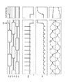
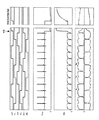
先の実施の形態1では、1パルス通電方式として180度通電制御を行った際の短絡故障検出について説明した。これに対して、本実施の形態2では、1パルス通電方式として120度通電制御を行った際の短絡故障検出について説明する。すなわち、先の図1の構成において、通電角120度の1パルス通電制御を適用してモータジェネレータ9を駆動した場合の、短絡故障発生時を含む各部の動作波形について説明する。図3は、本発明の実施の形態2における120度通電制御時の各部の動作波形の説明図であり、各波形項目は、先の図2と同じである。
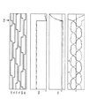
先の実施の形態1、2では、1パルス通電方式としてそれぞれ、180度通電制御、120度通電制御を行った際の短絡故障検出について説明した。これに対して、本実施の形態3では、1パルス通電方式の代わりに同期整流制御を行った際の短絡故障検出について説明する。すなわち、先の図1の構成において、モータジェネレータ9の発電モードにて同期整流制御を行った場合の、短絡発生時を含む各部の動作波形について説明する。図4は、本発明の実施の形態3における同期整流制御時の各部の動作波形の説明図であり、各波形項目は、先の図2と同じである。
Claims (6)
- 第1の主端子と第2の主端子と制御端子とを有する半導体スイッチで構成された3相ブリッジ型の電力変換回路と、
前記半導体スイッチの動作を制御する制御回路と、
前記電力変換回路の直流端子間の電圧を監視する電圧検出回路と
を備えた電力変換装置であって、
前記制御回路は、前記電圧検出回路によって検出された前記電力変換回路の直流端子間の電圧が、所定値より小さい状態が所定時間以上継続した場合に、前記半導体スイッチを遮断する保護機能を備える電力変換装置。 - 請求項1に記載の電力変換装置において、
前記制御回路は、前記所定値として前記電力変換回路が正常時の動作で到達する最低電圧よりも小さい電圧が設定されている電力変換装置。 - 請求項2に記載の電力変換装置において、
前記制御回路は、前記電力変換回路が直流電力を交流電力に変換する動作時に、前記半導体スイッチを1パルス通電制御方式にて制御する電力変換装置。 - 請求項3に記載の電力変換装置において、
前記制御回路は、前記1パルス通電制御方式として通電角180度または120度の1パルス通電制御を行う電力変換装置。 - 請求項2に記載の電力変換装置において、
前記制御回路は、前記電力変換回路が交流電力を直流電力に変換する動作時に、前記電力変換回路での3相全波整流において各半導体スイッチが通電する位相区間内で前記半導体スイッチをオンさせる同期整流制御方式にて前記半導体スイッチを制御する電力変換装置。 - 請求項3ないし5のいずれか1項に記載の電力変換装置において、
前記制御回路において前記1パルス通電制御方式または前記同期整流制御方式を採用することで、前記直流端子間の電圧を平滑化するための大容量コンデンサを不要とする電力変換装置。
Priority Applications (3)
| Application Number | Priority Date | Filing Date | Title |
|---|---|---|---|
| JP2008314276A JP4772104B2 (ja) | 2008-12-10 | 2008-12-10 | 電力変換装置 |
| US12/431,182 US8797768B2 (en) | 2008-12-10 | 2009-04-28 | Power conversion device including short circuit detection device |
| FR0953686A FR2939577B1 (fr) | 2008-12-10 | 2009-06-04 | Dispositif de conversion d'energie |
Applications Claiming Priority (1)
| Application Number | Priority Date | Filing Date | Title |
|---|---|---|---|
| JP2008314276A JP4772104B2 (ja) | 2008-12-10 | 2008-12-10 | 電力変換装置 |
Publications (2)
| Publication Number | Publication Date |
|---|---|
| JP2010141990A true JP2010141990A (ja) | 2010-06-24 |
| JP4772104B2 JP4772104B2 (ja) | 2011-09-14 |
Family
ID=42211702
Family Applications (1)
| Application Number | Title | Priority Date | Filing Date |
|---|---|---|---|
| JP2008314276A Expired - Fee Related JP4772104B2 (ja) | 2008-12-10 | 2008-12-10 | 電力変換装置 |
Country Status (3)
| Country | Link |
|---|---|
| US (1) | US8797768B2 (ja) |
| JP (1) | JP4772104B2 (ja) |
| FR (1) | FR2939577B1 (ja) |
Cited By (3)
| Publication number | Priority date | Publication date | Assignee | Title |
|---|---|---|---|---|
| WO2015045107A1 (ja) * | 2013-09-27 | 2015-04-02 | 三菱電機株式会社 | 突入電流制限回路、及び電力変換装置 |
| DE102017101387A1 (de) | 2016-01-27 | 2017-07-27 | Denso Corporation | Leistungsumwandlungsvorrichtung |
| JP2017189075A (ja) * | 2016-04-08 | 2017-10-12 | 株式会社デンソー | 回転電機の制御装置 |
Families Citing this family (8)
| Publication number | Priority date | Publication date | Assignee | Title |
|---|---|---|---|---|
| IN2014CN04075A (ja) * | 2011-12-05 | 2015-09-04 | Abb Technology Ag | |
| JP6041862B2 (ja) * | 2012-03-05 | 2016-12-14 | 富士電機株式会社 | 電力変換装置 |
| JP2014236530A (ja) | 2013-05-30 | 2014-12-15 | 富士電機株式会社 | 電力変換装置 |
| FR3033955B1 (fr) * | 2015-03-17 | 2017-03-17 | Valeo Systemes Thermiques | Dispositif de pilotage d'alimentation electrique de circuit pour un vehicule comprenant une batterie et ensemble correspondant |
| DE112016006497T5 (de) * | 2016-02-26 | 2019-02-28 | Vacon Oy | Ein elektronischer Umrichter und ein Verfahren zum Steuern von diesem |
| DE102017205481A1 (de) * | 2017-03-31 | 2018-10-04 | Robert Bosch Gmbh | Gleichspannungskonverter, Spannungsversorgungseinrichtung und Diagnoseverfahren für einen Gleichspannungskonverter |
| CN113556052B (zh) * | 2021-07-23 | 2022-12-23 | 重庆和诚电器有限公司 | 一种摩托车用mos开关式调压器的控制方法 |
| FR3153707B1 (fr) * | 2023-09-28 | 2025-10-10 | Safran Electrical & Power | Procédé de protection contre les courts circuits pour un convertisseur de puissance à MOSFET branché à un réseau d’alimentation continue |
Citations (6)
| Publication number | Priority date | Publication date | Assignee | Title |
|---|---|---|---|---|
| JPS5740325A (en) * | 1980-08-18 | 1982-03-05 | Mitsubishi Electric Corp | Shortcircuit protecting device |
| JPH1167483A (ja) * | 1997-08-26 | 1999-03-09 | Matsushita Electric Works Ltd | 放電灯点灯装置 |
| JP2001238484A (ja) * | 2000-02-22 | 2001-08-31 | Matsushita Electric Ind Co Ltd | インバータ装置 |
| JP2001275392A (ja) * | 2000-03-29 | 2001-10-05 | Fujitsu General Ltd | モータの制御方法およびその装置 |
| JP2005304143A (ja) * | 2004-04-08 | 2005-10-27 | Mitsubishi Electric Corp | 電力変換装置 |
| WO2007122701A1 (ja) * | 2006-04-19 | 2007-11-01 | Mitsubishi Denki Kabushiki Kaisha | コンバータ装置 |
Family Cites Families (13)
| Publication number | Priority date | Publication date | Assignee | Title |
|---|---|---|---|---|
| JPH0662553A (ja) * | 1992-08-04 | 1994-03-04 | Nippondenso Co Ltd | 車両用三相交流発電電動機 |
| JPH0723998U (ja) * | 1993-09-30 | 1995-05-02 | 日新電機株式会社 | インバータの短絡検出回路 |
| JPH07170759A (ja) * | 1993-12-13 | 1995-07-04 | Nippon Electric Ind Co Ltd | 電力変換装置におけるブリッジ回路の短絡検出方法 |
| JPH07250482A (ja) * | 1994-03-10 | 1995-09-26 | Toshiba Corp | Igbt短絡保護回路 |
| JPH0880059A (ja) * | 1994-09-05 | 1996-03-22 | Fuji Electric Co Ltd | 共振形インバータの短絡保護回路 |
| US6577097B2 (en) * | 2001-08-13 | 2003-06-10 | Delphi Technologies, Inc. | Method and system for controlling a synchronous machine using a changeable cycle-conduction angle |
| US6917179B2 (en) * | 2001-10-25 | 2005-07-12 | Toyota Jidosha Kabushiki Kaisha | Load driver and control method for safely driving DC load and computer-readable recording medium with program recorded thereon for allowing computer to execute the control |
| JP2004289903A (ja) * | 2003-03-20 | 2004-10-14 | Toyota Motor Corp | インバータ装置 |
| JP4223331B2 (ja) * | 2003-06-13 | 2009-02-12 | 株式会社日立製作所 | 電力制御用半導体素子の保護装置及びそれを備えた電力変換装置 |
| JP4359760B2 (ja) * | 2003-10-31 | 2009-11-04 | 国産電機株式会社 | 磁石発電機を備えた発電装置 |
| JP4140552B2 (ja) * | 2004-04-28 | 2008-08-27 | トヨタ自動車株式会社 | 自動車用電源装置およびそれを備える自動車 |
| JP4021431B2 (ja) * | 2004-08-10 | 2007-12-12 | ファナック株式会社 | コンバータ装置、インバータ装置及びdcリンク電圧の制御方法 |
| JP4491434B2 (ja) * | 2006-05-29 | 2010-06-30 | トヨタ自動車株式会社 | 電力制御装置およびそれを備えた車両 |
-
2008
- 2008-12-10 JP JP2008314276A patent/JP4772104B2/ja not_active Expired - Fee Related
-
2009
- 2009-04-28 US US12/431,182 patent/US8797768B2/en active Active
- 2009-06-04 FR FR0953686A patent/FR2939577B1/fr not_active Expired - Fee Related
Patent Citations (6)
| Publication number | Priority date | Publication date | Assignee | Title |
|---|---|---|---|---|
| JPS5740325A (en) * | 1980-08-18 | 1982-03-05 | Mitsubishi Electric Corp | Shortcircuit protecting device |
| JPH1167483A (ja) * | 1997-08-26 | 1999-03-09 | Matsushita Electric Works Ltd | 放電灯点灯装置 |
| JP2001238484A (ja) * | 2000-02-22 | 2001-08-31 | Matsushita Electric Ind Co Ltd | インバータ装置 |
| JP2001275392A (ja) * | 2000-03-29 | 2001-10-05 | Fujitsu General Ltd | モータの制御方法およびその装置 |
| JP2005304143A (ja) * | 2004-04-08 | 2005-10-27 | Mitsubishi Electric Corp | 電力変換装置 |
| WO2007122701A1 (ja) * | 2006-04-19 | 2007-11-01 | Mitsubishi Denki Kabushiki Kaisha | コンバータ装置 |
Cited By (6)
| Publication number | Priority date | Publication date | Assignee | Title |
|---|---|---|---|---|
| WO2015045107A1 (ja) * | 2013-09-27 | 2015-04-02 | 三菱電機株式会社 | 突入電流制限回路、及び電力変換装置 |
| JPWO2015045107A1 (ja) * | 2013-09-27 | 2017-03-02 | 三菱電機株式会社 | 電力変換装置 |
| US9590554B2 (en) | 2013-09-27 | 2017-03-07 | Mitsubishi Electric Corporation | Electric power converter |
| DE102017101387A1 (de) | 2016-01-27 | 2017-07-27 | Denso Corporation | Leistungsumwandlungsvorrichtung |
| JP2017135850A (ja) * | 2016-01-27 | 2017-08-03 | 株式会社デンソー | 電力変換装置 |
| JP2017189075A (ja) * | 2016-04-08 | 2017-10-12 | 株式会社デンソー | 回転電機の制御装置 |
Also Published As
| Publication number | Publication date |
|---|---|
| FR2939577A1 (fr) | 2010-06-11 |
| US8797768B2 (en) | 2014-08-05 |
| JP4772104B2 (ja) | 2011-09-14 |
| US20100142235A1 (en) | 2010-06-10 |
| FR2939577B1 (fr) | 2020-01-10 |
Similar Documents
| Publication | Publication Date | Title |
|---|---|---|
| JP4772104B2 (ja) | 電力変換装置 | |
| JP6157752B2 (ja) | 多相交流モータ駆動用インバータ装置 | |
| JP4968698B2 (ja) | 電動機の制御装置 | |
| JP5352570B2 (ja) | 回転機の制御装置,回転機系,車両,電気自動車または発電システム | |
| US6239566B1 (en) | Drive system for a permanently excited electric motor having at least one phase winding | |
| CN109039221B (zh) | 一种主动短路电路以及电机控制器 | |
| JP6091632B2 (ja) | 電力変換装置 | |
| CN101682292B (zh) | 逆变器装置及其输出电压检测方法 | |
| CN101277089A (zh) | 电机驱动装置及电机驱动方法 | |
| US12110068B2 (en) | Control for electric power steering | |
| JP2014042363A (ja) | 車両用回転電機 | |
| JP2015192526A (ja) | 負荷駆動装置 | |
| JP2010252536A (ja) | インバータ装置及びその故障診断方法 | |
| US20200083880A1 (en) | Motor drive device and electric power steering device | |
| JP2018160972A (ja) | モータ駆動回路の制御装置及びモータ駆動回路の診断方法 | |
| JPWO2018180238A1 (ja) | 電力変換装置、モータ駆動ユニットおよび電動パワーステアリング装置 | |
| JP2005304143A (ja) | 電力変換装置 | |
| JP6230677B1 (ja) | 回転電機の制御装置および制御方法 | |
| JP2013511247A (ja) | インバータ | |
| JP2012239247A (ja) | モータ制御装置 | |
| JP5893383B2 (ja) | 電力変換装置 | |
| JP4369500B2 (ja) | 回転電機装置 | |
| JP3999226B2 (ja) | 電動機制御装置 | |
| JP7002619B1 (ja) | 電力変換装置 | |
| WO2019049449A1 (ja) | 電力変換装置、モータモジュールおよび電動パワーステアリング装置 |
Legal Events
| Date | Code | Title | Description |
|---|---|---|---|
| A977 | Report on retrieval |
Free format text: JAPANESE INTERMEDIATE CODE: A971007 Effective date: 20101015 |
|
| A131 | Notification of reasons for refusal |
Free format text: JAPANESE INTERMEDIATE CODE: A131 Effective date: 20101026 |
|
| A521 | Request for written amendment filed |
Free format text: JAPANESE INTERMEDIATE CODE: A523 Effective date: 20101129 |
|
| TRDD | Decision of grant or rejection written | ||
| A01 | Written decision to grant a patent or to grant a registration (utility model) |
Free format text: JAPANESE INTERMEDIATE CODE: A01 Effective date: 20110524 |
|
| A61 | First payment of annual fees (during grant procedure) |
Free format text: JAPANESE INTERMEDIATE CODE: A61 Effective date: 20110621 |
|
| FPAY | Renewal fee payment (event date is renewal date of database) |
Free format text: PAYMENT UNTIL: 20140701 Year of fee payment: 3 |
|
| R150 | Certificate of patent or registration of utility model |
Free format text: JAPANESE INTERMEDIATE CODE: R150 Ref document number: 4772104 Country of ref document: JP Free format text: JAPANESE INTERMEDIATE CODE: R150 |
|
| R250 | Receipt of annual fees |
Free format text: JAPANESE INTERMEDIATE CODE: R250 |
|
| R250 | Receipt of annual fees |
Free format text: JAPANESE INTERMEDIATE CODE: R250 |
|
| R250 | Receipt of annual fees |
Free format text: JAPANESE INTERMEDIATE CODE: R250 |
|
| R250 | Receipt of annual fees |
Free format text: JAPANESE INTERMEDIATE CODE: R250 |
|
| R250 | Receipt of annual fees |
Free format text: JAPANESE INTERMEDIATE CODE: R250 |
|
| R250 | Receipt of annual fees |
Free format text: JAPANESE INTERMEDIATE CODE: R250 |
|
| R250 | Receipt of annual fees |
Free format text: JAPANESE INTERMEDIATE CODE: R250 |
|
| R250 | Receipt of annual fees |
Free format text: JAPANESE INTERMEDIATE CODE: R250 |
|
| LAPS | Cancellation because of no payment of annual fees |