JP2007535773A - Free space pointing device and pointing method - Google Patents
Free space pointing device and pointing method Download PDFInfo
- Publication number
- JP2007535773A JP2007535773A JP2007511062A JP2007511062A JP2007535773A JP 2007535773 A JP2007535773 A JP 2007535773A JP 2007511062 A JP2007511062 A JP 2007511062A JP 2007511062 A JP2007511062 A JP 2007511062A JP 2007535773 A JP2007535773 A JP 2007535773A
- Authority
- JP
- Japan
- Prior art keywords
- pointing device
- rotation
- output
- user
- sensor
- Prior art date
- Legal status (The legal status is an assumption and is not a legal conclusion. Google has not performed a legal analysis and makes no representation as to the accuracy of the status listed.)
- Withdrawn
Links
Images


Classifications
-
- G—PHYSICS
- G06—COMPUTING; CALCULATING OR COUNTING
- G06F—ELECTRIC DIGITAL DATA PROCESSING
- G06F3/00—Input arrangements for transferring data to be processed into a form capable of being handled by the computer; Output arrangements for transferring data from processing unit to output unit, e.g. interface arrangements
- G06F3/01—Input arrangements or combined input and output arrangements for interaction between user and computer
- G06F3/03—Arrangements for converting the position or the displacement of a member into a coded form
- G06F3/033—Pointing devices displaced or positioned by the user, e.g. mice, trackballs, pens or joysticks; Accessories therefor
- G06F3/0346—Pointing devices displaced or positioned by the user, e.g. mice, trackballs, pens or joysticks; Accessories therefor with detection of the device orientation or free movement in a 3D space, e.g. 3D mice, 6-DOF [six degrees of freedom] pointers using gyroscopes, accelerometers or tilt-sensors
-
- G—PHYSICS
- G06—COMPUTING; CALCULATING OR COUNTING
- G06F—ELECTRIC DIGITAL DATA PROCESSING
- G06F1/00—Details not covered by groups G06F3/00 - G06F13/00 and G06F21/00
- G06F1/26—Power supply means, e.g. regulation thereof
- G06F1/32—Means for saving power
- G06F1/3203—Power management, i.e. event-based initiation of a power-saving mode
- G06F1/3206—Monitoring of events, devices or parameters that trigger a change in power modality
- G06F1/3215—Monitoring of peripheral devices
-
- G—PHYSICS
- G06—COMPUTING; CALCULATING OR COUNTING
- G06F—ELECTRIC DIGITAL DATA PROCESSING
- G06F1/00—Details not covered by groups G06F3/00 - G06F13/00 and G06F21/00
- G06F1/26—Power supply means, e.g. regulation thereof
- G06F1/32—Means for saving power
- G06F1/3203—Power management, i.e. event-based initiation of a power-saving mode
- G06F1/3234—Power saving characterised by the action undertaken
- G06F1/325—Power saving in peripheral device
- G06F1/3259—Power saving in cursor control device, e.g. mouse, joystick, trackball
-
- G—PHYSICS
- G06—COMPUTING; CALCULATING OR COUNTING
- G06F—ELECTRIC DIGITAL DATA PROCESSING
- G06F21/00—Security arrangements for protecting computers, components thereof, programs or data against unauthorised activity
- G06F21/30—Authentication, i.e. establishing the identity or authorisation of security principals
- G06F21/31—User authentication
-
- G—PHYSICS
- G06—COMPUTING; CALCULATING OR COUNTING
- G06F—ELECTRIC DIGITAL DATA PROCESSING
- G06F3/00—Input arrangements for transferring data to be processed into a form capable of being handled by the computer; Output arrangements for transferring data from processing unit to output unit, e.g. interface arrangements
- G06F3/01—Input arrangements or combined input and output arrangements for interaction between user and computer
- G06F3/03—Arrangements for converting the position or the displacement of a member into a coded form
- G06F3/033—Pointing devices displaced or positioned by the user, e.g. mice, trackballs, pens or joysticks; Accessories therefor
- G06F3/038—Control and interface arrangements therefor, e.g. drivers or device-embedded control circuitry
- G06F3/0383—Signal control means within the pointing device
-
- G—PHYSICS
- G06—COMPUTING; CALCULATING OR COUNTING
- G06V—IMAGE OR VIDEO RECOGNITION OR UNDERSTANDING
- G06V40/00—Recognition of biometric, human-related or animal-related patterns in image or video data
- G06V40/20—Movements or behaviour, e.g. gesture recognition
-
- H—ELECTRICITY
- H04—ELECTRIC COMMUNICATION TECHNIQUE
- H04N—PICTORIAL COMMUNICATION, e.g. TELEVISION
- H04N21/00—Selective content distribution, e.g. interactive television or video on demand [VOD]
- H04N21/40—Client devices specifically adapted for the reception of or interaction with content, e.g. set-top-box [STB]; Operations thereof
- H04N21/41—Structure of client; Structure of client peripherals
- H04N21/422—Input-only peripherals, i.e. input devices connected to specially adapted client devices, e.g. global positioning system [GPS]
- H04N21/42204—User interfaces specially adapted for controlling a client device through a remote control device; Remote control devices therefor
- H04N21/42206—User interfaces specially adapted for controlling a client device through a remote control device; Remote control devices therefor characterized by hardware details
- H04N21/42222—Additional components integrated in the remote control device, e.g. timer, speaker, sensors for detecting position, direction or movement of the remote control, microphone or battery charging device
-
- G—PHYSICS
- G06—COMPUTING; CALCULATING OR COUNTING
- G06F—ELECTRIC DIGITAL DATA PROCESSING
- G06F2203/00—Indexing scheme relating to G06F3/00 - G06F3/048
- G06F2203/038—Indexing scheme relating to G06F3/038
- G06F2203/0383—Remote input, i.e. interface arrangements in which the signals generated by a pointing device are transmitted to a PC at a remote location, e.g. to a PC in a LAN
-
- G—PHYSICS
- G06—COMPUTING; CALCULATING OR COUNTING
- G06F—ELECTRIC DIGITAL DATA PROCESSING
- G06F2203/00—Indexing scheme relating to G06F3/00 - G06F3/048
- G06F2203/038—Indexing scheme relating to G06F3/038
- G06F2203/0384—Wireless input, i.e. hardware and software details of wireless interface arrangements for pointing devices
-
- Y—GENERAL TAGGING OF NEW TECHNOLOGICAL DEVELOPMENTS; GENERAL TAGGING OF CROSS-SECTIONAL TECHNOLOGIES SPANNING OVER SEVERAL SECTIONS OF THE IPC; TECHNICAL SUBJECTS COVERED BY FORMER USPC CROSS-REFERENCE ART COLLECTIONS [XRACs] AND DIGESTS
- Y02—TECHNOLOGIES OR APPLICATIONS FOR MITIGATION OR ADAPTATION AGAINST CLIMATE CHANGE
- Y02D—CLIMATE CHANGE MITIGATION TECHNOLOGIES IN INFORMATION AND COMMUNICATION TECHNOLOGIES [ICT], I.E. INFORMATION AND COMMUNICATION TECHNOLOGIES AIMING AT THE REDUCTION OF THEIR OWN ENERGY USE
- Y02D10/00—Energy efficient computing, e.g. low power processors, power management or thermal management
Abstract
本発明によるシステムおよび方法は、少なくとも1つのセンサを使用してハンドヘルドデバイスの動きを検出するハンドヘルドデバイス、例えば、自由空間ポインティングデバイスを提供することにより、以上、およびその他の必要性に応える。検出された動きは、次に、所望される出力に、例えば、カーソルの動きにマップされる。 The system and method according to the present invention addresses these and other needs by providing a handheld device, such as a free space pointing device, that uses at least one sensor to detect movement of the handheld device. The detected movement is then mapped to the desired output, eg, cursor movement.
Description
関連出願
本出願は、参照により開示が本明細書に組み込まれている、「Freespace Pointing Device」という名称の2004年4月30日に出願した米国特許仮出願第60/566,444号に関連し、第60/566,444号の優先権を主張する。また、本出願は、参照により開示が本明細書に組み込まれている、「Free Space Pointing Devices and Methods」という名称の2004年9月23日に出願した米国特許仮出願第60/612,571号にも関連し、第60/612,571号の優先権も主張する。また、本出願は、参照により開示が本明細書に組み込まれている、「Methods and Devices for Removing Unintentional Movement in Free Space Pointing Devices」という名称の2005年1月5日に出願した米国特許仮出願第60/641,383号にも関連し、第60/641,383号の優先権も主張する。また、本出願は、参照により開示が本明細書に組み込まれている、「Freespace Pointing Devices and Methods for Using Same」という名称の2005年1月5日に出願した米国特許仮出願第60/641,410号にも関連し、第60/641,410号の優先権も主張する。また、本出願は、参照により開示が本明細書に組み込まれている、「Handheld Remote Control Device」という名称の2005年1月5日に出願した米国特許仮出願第60/641,405号にも関連し、第60/641,405号の優先権も主張する。また、本出願は、すべて同時に出願し、すべて参照により本明細書に組み込まれている、「Methods and Devices for Removing Unintentional Movement in Free Space Pointing Devices」、「Free Space Pointing Devices with Tilt Compensation and Improved Usability」、「Methods and Devices for Identifying Users Based on Tremor」という名称の米国特許出願第11/119,987号、第11/119,719号、および第11/119,688号にも関連する。
This application is related to US Provisional Application No. 60 / 566,444 filed Apr. 30, 2004 entitled "Freespace Pointing Device", the disclosure of which is incorporated herein by reference. Claim priority of 60 / 566,444. This application is also incorporated in US Provisional Patent Application No. 60 / 612,571, filed September 23, 2004, entitled “Free Space Pointing Devices and Methods,” whose disclosure is incorporated herein by reference. Relatedly, the priority of 60 / 612,571 is also claimed. This application is also a U.S. provisional application filed January 5, 2005, entitled `` Methods and Devices for Removing Unintentional Movement in Free Space Pointing Devices '', the disclosure of which is incorporated herein by reference. It also relates to 60 / 641,383 and claims the priority of 60 / 641,383. This application is also a
本発明は、自由空間ポインティング技術、ポインティングシステム、およびポインティングデバイス、ならびに他のタイプのハンドヘルドデバイスにおいて使用可能ないくつかの技術およびデバイスを説明する。 The present invention describes several techniques and devices that can be used in free space pointing techniques, pointing systems, and pointing devices, as well as other types of handheld devices.
情報通信に関連する技術は、ここ数十年の間に急速に進化している。テレビ、セルラー電話機、インターネット、およびオプションの通信技術(いくつかだけを挙げると)が一緒になってもたらす利用可能な情報、およびエンターテイメントオプションの洪水に、消費者は見舞われている。テレビを例にとると、この30年間に、ケーブルテレビサービス、衛星テレビサービス、従量料金制の映画およびビデオオンデマンドが導入されている。1960年代のテレビ視聴者は、おそらく4つ、または5つの放送TVチャネルを通常、受信することができたのに対して、今日のTV視聴者は、数百チャネル、数千チャネル、また、場合により、数百万チャネルのショーおよび情報から選択する機会を有する。ホテルなどで現在、主に使用されているビデオオンデマンド技術は、数千の映画タイトルからのホームエンターテイメント選択の可能性を提供する。 Technologies related to information and communication have evolved rapidly over the last few decades. Consumers are hit by the flood of information and entertainment options that TV, cellular phones, the Internet, and optional communication technologies (to name only a few) bring together. Taking television as an example, cable TV services, satellite TV services, pay-per-use movies and video on demand have been introduced in the last 30 years. TV viewers in the 1960s could probably receive four or five broadcast TV channels normally, whereas today's TV viewers have hundreds, thousands or even channels With the opportunity to choose from millions of channel shows and information. Video-on-demand technology, currently used primarily in hotels and the like, offers the possibility of home entertainment selection from thousands of movie titles.
エンドユーザにそれほど多くの情報およびコンテンツを提供する技術能力は、機会とともに課題も、システム設計者およびサービスプロバイダにもたらす。1つの課題は、エンドユーザが、より少ない選択肢ではなく、より多くの選択肢を有することを通常、選好する一方で、この選好は、選択プロセスが迅速であるとともに簡単であることの欲求と天秤に掛けられる。残念ながら、エンドユーザがメディアアイテムにアクセスするシステムおよびインタフェースの進展は、迅速でも簡単でもない選択プロセスをもたらしている。テレビ番組の例を再び考慮されたい。テレビの揺籃期には、いずれの番組を観るかを決めることは、選択肢の数が少なかったことに主に起因して、比較的簡単なプロセスであった。人は、例えば、(1)近くのテレビチャネル、(2)それらのチャネルで送信される番組、および(3)日付と時刻の間の対応を示す一連の列と行としてフォーマットされた、印刷された案内を調べた。テレビが、チューナノブを調整することによって所望のチャネルにチューニングが合わせられ、視聴者は、選択された番組を観た。後に、視聴者が、テレビを離れたところからチューニングすることを可能にするリモコンデバイスが導入された。このユーザ‐テレビインタフェースの追加は、視聴者が、いくつかのチャネルで放送されている短いセグメントを敏速に観て、任意の所与の時点でどのような番組が選択可能であるかを素早く知ることができる、「チャネルサーフィン」として知られる現象を生じさせた。 The technical ability to provide so much information and content to end users presents challenges as well as opportunities for system designers and service providers. One challenge is that end users usually prefer to have more options, not fewer options, while this preference is in the desire and balance that the selection process is quick and simple. It is hung. Unfortunately, the development of systems and interfaces for end-user access to media items has led to a selection process that is neither quick nor easy. Consider again the example of a television program. In the early days of television, deciding which program to watch was a relatively simple process, mainly due to the small number of options. A person is printed, for example, formatted as a series of columns and rows indicating the correspondence between (1) nearby television channels, (2) programs transmitted on those channels, and (3) date and time. I looked up the guidance. The television was tuned to the desired channel by adjusting the tunable, and the viewer watched the selected program. Later, remote control devices were introduced that allow viewers to tune the television from a distance. The addition of this user-TV interface allows viewers to quickly watch short segments broadcast on several channels and quickly know what programs are available at any given time. It has caused a phenomenon known as “channel surfing”.
チャネルの数、および視聴可能なコンテンツの量が劇的に増加したことにもかかわらず、テレビに関する一般に利用可能なユーザインタフェース、コントロールデバイスオプション、およびフレームワークは、ここ30年間であまり変化していない。印刷された案内が、依然として、番組情報を伝えるための最も普及した機構である。上向き矢印と下向き矢印を有する複数ボタンリモコンが、依然として、最も普及しているチャネル/コンテンツ選択機構である。利用可能なメディアコンテンツの増加に対する、TVユーザインタフェースを設計し、実施する人々の反応は、既存の選択手続きおよびインタフェースオブジェクトの単純明快な拡張であった。このため、印刷された案内における行の数は、より多くのチャネルに対応するように増やされた。リモコンデバイス上のボタンの数は、例えば、図1に示されるとおり、さらなる機能およびコンテンツの取り扱いをサポートするように増やされた。しかし、このアプローチは、視聴者が、利用可能な情報を点検するのに要求される時間と、選択を実施するのに要求されるアクションの複雑さをともに大幅に増大させた。消費者は、消費者が既に、遅すぎ、複雑すぎると見なしているインタフェースの複雑さを増大させる新たなサービスに抵抗を示すので、既存のインタフェースの面倒な性質は、一部のサービス、例えば、ビデオオンデマンドの商業的実施を阻害してきたといえる。 Despite the dramatic increase in the number of channels and the amount of content available for viewing, publicly available user interfaces, control device options, and frameworks for television have not changed much over the last 30 years. . Printed guidance is still the most popular mechanism for conveying program information. Multi-button remote controls with up and down arrows are still the most popular channel / content selection mechanism. The reaction of people designing and implementing TV user interfaces to the increase in available media content has been a straightforward extension of existing selection procedures and interface objects. For this reason, the number of lines in the printed guide has been increased to accommodate more channels. The number of buttons on the remote control device has been increased to support further functionality and content handling, for example, as shown in FIG. However, this approach has greatly increased both the time required for viewers to review the available information and the complexity of actions required to perform the selection. Since consumers resist resistance to new services that increase the complexity of interfaces that consumers already consider too slow and too complex, the cumbersome nature of existing interfaces can make some services, for example, It can be said that the commercial implementation of video-on-demand has been hindered.
帯域幅とコンテンツの増加に加えて、ユーザインタフェースがネックとなる問題は、技術の集約によって悪化させられている。消費者は、いくつかの分離されたコンポーネントよりはむしろ、統合されたシステムを購入するオプションを有することに肯定的に反応している。この傾向の例が、3つの以前は独立していたコンポーネントが、今日では、しばしば、統合されたユニットとして販売される、一体型のテレビ/VCR/DVDである。この傾向は、続く可能性が高く、家庭で現在、見られる、すべてではないにしても、ほとんどの通信デバイスが、統合されたユニットとして、例えば、テレビ/VCR/DVD/インターネットアクセス/ラジオ/ステレオユニットとして一緒にひとまとめにされるという最終結果がもたらされる可能性がある。別々のコンポーネントを購入し続ける人々でさえ、それらの別々のコンポーネントのシームレスな制御、および相互動作を所望する可能性が高い。この向上した集約には、ユーザインタフェースがより複雑になる可能性が伴う。例えば、いわゆる「汎用」リモートユニットが、例えば、TVリモートユニットとVCRリモートユニットの機能を組み合わせるように導入された際、それらの汎用リモートユニット上のボタンの数は、TVリモートユニット上、またはVCRリモートユニット上で個々に存在するボタンの数より、通常、多かった。この増えたボタン数および機能により、TVまたはVCRの最も単純な諸態様以外は何であれ、リモート上の厳密に正しいボタンを探し求めることなしに、制御することが非常に困難になる。多くの場合、それらの汎用リモートは、一部のTVに固有である多くのレベルの制御または機能にアクセスする十分なボタンを提供しない。それらのケースでは、元のデバイスリモートユニットが、依然として、必要とされ、集約の複雑さから生じるユーザインタフェース問題に起因して、複数のリモートを扱う元の煩わしさは、そのままである。一部のリモートユニットは、エキスパートコマンドでプログラミングされることが可能な「ソフト」ボタンを追加することにより、この問題に対処している。それらのソフトボタンは、ときとして、それらのボタンのアクションを示す、付随するLCDディスプレイを有する。それらのリモートユニットも、TVから目を離してリモコンに目を向けることなしに使用するのが困難であるという欠点を有する。それらのリモートユニットのさらに別の欠点は、ボタンの数を減らそうとして複数のモードを使用することである。それらの「モード付き」汎用リモートユニットでは、TV、DVDプレーヤ、ケーブルセットトップボックス、VCR、その他のいずれとリモートが通信するかを選択する特別なボタンが存在する。このことは、誤ったデバイスにコマンドを送信すること、リモートが正しいモードになっていることを確かめるためにユーザがリモートを見ることを余儀なくすることを含め、多くの操作性問題を生じさせ、複数のデバイスの統合を簡単にすることを全くもたらさない。それらの汎用リモートデバイスの最も進んだものは、複数のデバイスに対するコマンドシーケンスを、ユーザがリモートにプログラミングするのを可能にすることにより、ある程度の統合をもたらす。これは、あまりにも難しい作業であるため、多くのユーザは、ユーザの汎用リモートユニットをプログラミングするのにプロのインストール技術者を雇う。 In addition to increased bandwidth and content, the problem of user interface becoming a bottleneck has been exacerbated by technology aggregation. Consumers are positively responding to having the option to purchase an integrated system rather than some separate components. An example of this trend is the integrated TV / VCR / DVD, where three previously independent components are now often sold as integrated units. This trend is likely to continue and most, if not all, communication devices currently seen in the home are integrated units such as TV / VCR / DVD / Internet access / radio / stereo. The end result may be that they are grouped together as a unit. Even those who continue to purchase separate components are likely to desire seamless control and interaction of those separate components. This improved aggregation entails a more complex user interface. For example, when so-called “universal” remote units are introduced, for example, to combine the functions of a TV remote unit and a VCR remote unit, the number of buttons on those universal remote units is either on the TV remote unit or on the VCR remote unit. Usually more than the number of individual buttons on the unit. This increased number of buttons and functions make it very difficult to control without seeking the exact correct button on the remote, whatever the simplest aspects of the TV or VCR. In many cases, these universal remotes do not provide enough buttons to access many levels of controls or functions that are unique to some TVs. In those cases, the original device remote unit is still needed, and the original annoyance of handling multiple remotes remains due to user interface issues resulting from the complexity of aggregation. Some remote units address this problem by adding “soft” buttons that can be programmed with expert commands. The soft buttons sometimes have an associated LCD display that shows the action of those buttons. These remote units also have the drawback of being difficult to use without looking away from the TV and looking at the remote control. Yet another disadvantage of these remote units is the use of multiple modes in an attempt to reduce the number of buttons. In those “moded” general purpose remote units, there is a special button that selects whether the remote communicates with a TV, DVD player, cable set-top box, VCR, or others. This creates a number of usability problems, including sending commands to the wrong device and forcing the user to view the remote to make sure the remote is in the correct mode. It does not make any device integration easy. The most advanced of these general purpose remote devices provide some degree of integration by allowing the user to remotely program command sequences for multiple devices. This is so difficult that many users hire professional installation technicians to program their universal remote units.
また、エンドユーザとメディアシステムの間のスクリーンインタフェースを近代化するいくつかの試みも行われてきた。しかし、それらの試みは、いくつか欠点があるなかで、とりわけ、メディアアイテムの大きい集まりと、メディアアイテムの小さい集まりの間で用意にスケーリングを行うことができないという欠点を通常、抱えている。例えば、アイテムのリストに依拠するインタフェースは、メディアアイテムの小さい集まりの場合には、うまく機能するが、メディアアイテムの大きい集まりの場合は、ブラウズするのが面倒である。階層型ナビゲーション(例えば、ツリー構造)に依拠するインタフェースは、メディアアイテムの大きい集まりの場合、リストインタフェースよりも迅速に目を通すことできる可能性があるが、メディアアイテムの小さい集まりに直ちに適用可能ではない。加えて、ユーザは、ツリー構造において3つ以上のレイヤをユーザが通らなければならない選択プロセスには、関心を失う傾向がある。以上のケースのすべてに関して、現在のリモートユニットは、リストまたは階層を移動するのにアップボタンおよびダウンボタンをユーザが繰り返し押し下げることを余儀なくすることにより、以上の選択プロセッサをさらに面倒にしている。ページアップおよびページダウンのような選択スキップコントロールが利用可能な場合、ユーザは、通常、リモートを見て、それらの特別なボタンを見つけるか、またはそれらのボタンが存在していることすら知るのに、訓練されなければならない。したがって、ユーザとメディアシステムの間のコントロールインタフェースおよびスクリーンインタフェースを単純化するとともに、選択プロセスをスピードアップする一方で、ユーザへの多数のメディアアイテム、および新たなサービスの供給を円滑にすることにより、サービスプロバイダが、エンドユーザ機器に利用可能な帯域幅の増加を活用することを同時に可能にする、編成フレームワーク、編成技術、および編成システムが、参照により開示が本明細書に組み込まれている、「A Control Framework with a Zoomable Graphical User Interface for Organizing, Selecting and Launching Media Items」という名称の2004年1月30日に出願した、米国特許出願第10/768,432号で提案されている。 There have also been several attempts to modernize the screen interface between end users and media systems. However, these attempts usually have the disadvantage of not being able to scale well between a large collection of media items and a small collection of media items, among other disadvantages. For example, an interface that relies on a list of items works well for small collections of media items, but is cumbersome to browse for large collections of media items. Interfaces that rely on hierarchical navigation (e.g., tree structure) may look faster for large collections of media items than list interfaces, but may not be immediately applicable to small collections of media items. Absent. In addition, the user tends to lose interest in the selection process where the user must go through more than two layers in the tree structure. For all of the above cases, current remote units further complicate these selection processors by forcing the user to repeatedly press the up and down buttons to move through the list or hierarchy. When selection skip controls such as page up and page down are available, the user usually looks at the remote to find those special buttons or even knows that those buttons are present. Must be trained. Therefore, by simplifying the control interface and screen interface between the user and the media system and speeding up the selection process, while facilitating the provision of a large number of media items and new services to the user, An organization framework, organization technology, and organization system that simultaneously enable service providers to take advantage of the increased bandwidth available to end-user equipment, the disclosure of which is incorporated herein by reference, No. 10 / 768,432, filed Jan. 30, 2004, entitled “A Control Framework with a Zoomable Graphical User Interface for Organizing, Selecting and Launching Media Items”.
本明細書の特別な関心対象は、そのようなフレームワーク、ならびにその他のアプリケーションおよびシステムと対話するのに使用可能なリモートデバイスである。前段で組み込まれた出願で述べられるとおり、例えば、トラックボール、「マウス」タイプのポインティングデバイス、ライトペン、その他を含め、様々な異なるタイプのリモートデバイスが、そのようなフレームワークとともに使用されることが可能である。しかし、そのようなフレームワーク(および他のアプリケーション)とともに使用されることが可能な別のカテゴリのリモートデバイスは、自由空間ポインティングデバイスである。「自由空間ポインティング」という句は、本明細書では、入力デバイスが、例えば、ディスプレイスクリーンの前方の空中で、3(またはそれより多くの)次元で動く能力、およびユーザインタフェースが、それらの動きを、直接ユーザインタフェースコマンドに、例えば、ディスプレイスクリーン上のカーソルの動きに変換する、対応する能力を指す。自由空間ポインティングデバイス間のデータの転送は、無線で、または自由空間ポインティングデバイスを別のデバイスに接続する配線を介して実行されることが可能である。このため、「自由空間ポインティング」は例えば、表面、例えば、デスクトップ表面またはマウスパッドを代理表面として使用して、その表面から、マウスの相対的動きが、コンピュータディスプレイスクリーン上のカーソルの動きに変換される、従来のコンピュータマウスポインティング技術とは異なる。自由空間ポインティングデバイスの実施例は、米国特許第5,440,326号で見ることができる。 Of particular interest herein are remote devices that can be used to interact with such frameworks, as well as other applications and systems. As mentioned in the earlier incorporated application, various different types of remote devices may be used with such a framework, including, for example, trackballs, “mouse” type pointing devices, light pens, etc. Is possible. However, another category of remote devices that can be used with such frameworks (and other applications) are free space pointing devices. The phrase “free space pointing” refers herein to the ability of the input device to move in three (or more) dimensions, for example, in the air in front of the display screen, and the user interface , Refers to the corresponding ability to translate directly into user interface commands, eg, cursor movement on the display screen. Transfer of data between free space pointing devices can be performed wirelessly or via wiring that connects the free space pointing device to another device. Thus, “free space pointing” uses, for example, a surface, eg, a desktop surface or a mouse pad as a surrogate surface, from which the relative movement of the mouse is converted into cursor movement on a computer display screen. This is different from the conventional computer mouse pointing technology. An example of a free space pointing device can be found in US Pat. No. 5,440,326.
第'326号特許は、とりわけ、コンピュータのディスプレイ上のカーソルの位置を制御するためのポインティングデバイスとして使用されるように適合された垂直ジャイロスコープを説明している。ジャイロスコープのコアにおけるモータが、ハンドヘルドコントローラデバイスからの2対の直交するジンバルによって吊り下げられ、振子デバイスによってスピン軸を公称で垂直に配向されている。電気光学シャフト角エンコーダが、ユーザによってハンドヘルドコントローラデバイスが操作されると、デバイスの向きを感知し、結果の電気出力が、コンピュータディスプレイのスクリーン上のカーソルの動きを制御するのにコンピュータが使用できるフォーマットに変換される。 The '326 patent describes, among other things, a vertical gyroscope adapted to be used as a pointing device for controlling the position of a cursor on a computer display. The motor in the gyroscope core is suspended by two pairs of orthogonal gimbals from the handheld controller device and the spin axis is nominally vertically oriented by the pendulum device. A format that the electro-optic shaft angle encoder senses when the handheld controller device is manipulated by the user and the resulting electrical output can be used by the computer to control the movement of the cursor on the screen of the computer display Is converted to
しかし、おおむね、ハンドヘルドデバイス設計の分野において、より具体的には、自由空間ポインタ設計の分野において改良の相当な余地が存在する。
本発明によるシステムおよび方法は、少なくとも1つのセンサを使用してハンドヘルドデバイスの動きを検出するハンドヘルドデバイス、例えば、自由空間ポインティングデバイスを提供することにより、以上、およびその他の必要性に応える。検出された動きは、次に、所望される出力に、例えば、カーソルの動きにマップされる。 The system and method according to the present invention addresses these and other needs by providing a handheld device, such as a free space pointing device, that uses at least one sensor to detect movement of the handheld device. The detected movement is then mapped to the desired output, eg, cursor movement.
本発明の例示的な実施形態によれば、ポインティングデバイスは、第1の軸を中心とするポインティングデバイスの回転を測定し、その回転に関連する第1の回転出力を生成するための第1の回転センサと、第2の軸を中心とするポインティングデバイスの回転を測定し、その回転に関連する第2の回転出力を生成するための第2の回転センサと、ポインティングデバイスの加速度を測定し、その加速度に関連する加速度出力を出力するための加速度計と、その加速度に基づいて第1の回転出力、および第2の回転出力を変更するため、およびその変更された第1の回転出力、および第2の回転出力に基づいて出力を生成するための処理ユニットとを含む。 According to an exemplary embodiment of the present invention, a pointing device measures a rotation of the pointing device about a first axis and generates a first rotation output associated with the rotation. A rotation sensor, a second rotation sensor for measuring a rotation of the pointing device about the second axis, and generating a second rotation output related to the rotation; and an acceleration of the pointing device; An accelerometer for outputting an acceleration output related to the acceleration, a first rotation output and a second rotation output based on the acceleration, and the changed first rotation output; and And a processing unit for generating an output based on the second rotational output.
本発明の別の例示的な実施形態によれば、自由空間ポインティングを制御するための方法は、自由空間ポインティングデバイスに関連する動きの欠如を検出するステップと、検出するステップの結果、自由空間ポインティングデバイスを低電力状態にするステップとを含む。 According to another exemplary embodiment of the present invention, a method for controlling free space pointing includes detecting a lack of motion associated with a free space pointing device, and detecting the free space pointing as a result of the detecting step. Putting the device into a low power state.
本発明のさらに別の例示的な実施形態によれば、システムを制御するための方法は、デバイスに関連する動きを検出するステップと、デバイスが、現在、ユーザによって把持されていることを動きが示すかどうかを判定するステップと、判定するステップの結果に基づいてシステムを制御するステップとを含む。 According to yet another exemplary embodiment of the present invention, a method for controlling a system includes detecting a motion associated with a device and determining that the device is currently being gripped by a user. Determining whether to indicate, and controlling the system based on the result of the determining step.
添付の図面は、本発明の例示的な諸実施形態を示す。 The accompanying drawings illustrate exemplary embodiments of the invention.
本発明の以下の詳細な説明は、添付の図面を参照する。異なる図面における同一の符号は、同一または同様の要素を識別する。また、以下の詳細な説明は、本発明を限定しない。代わりに、本発明の範囲は、添付の特許請求の範囲によって定義される。 The following detailed description of the invention refers to the accompanying drawings. The same reference numbers in different drawings identify the same or similar elements. Also, the following detailed description does not limit the invention. Instead, the scope of the invention is defined by the appended claims.
以下の説明のいくらかの文脈を提供するため、本発明が実施されることが可能な例示的な集約されたメディアシステム200をまず、図2に関連して説明する。しかし、本発明は、そのタイプのメディアシステムにおける実施に限定されず、より多い、またはより少ないコンポーネントがシステムに含まれることも可能であることが、当業者には理解されよう。システム200では、入出力(I/O)バス210が、メディアシステム200内のシステムコンポーネントを一緒に接続している。I/Oバス210は、メディアシステムコンポーネント間で信号を転送するための、いくつかの異なる機構および技術のいずれかを表す。例えば、I/Oバス210には、オーディオ信号を転送する適切な数の独立したオーディオ「パッチ」ケーブル、ビデオ信号を転送する同軸ケーブル、制御信号を転送する2線シリアル回線または無線周波数トランシーバ、その他のタイプの信号を転送する光ファイバまたは任意の他のルーティング機構が含まれることが可能である。
In order to provide some context for the following description, an exemplary aggregated
この例示的な実施形態では、メディアシステム200は、I/Oバス210に結合されたテレビ/モニタ212、ビデオカセットレコーダ(VCR)214、デジタルビデオディスク(DVD)レコーダ/再生デバイス216、オーディオ/ビデオチューナ218、およびコンパクトディスクプレーヤ220を含む。VCR214、DVD216、およびコンパクトディスクプレーヤ220は、単一のディスク、または単一のカセットデバイスであることが可能であり、あるいは代替的に、複数のディスク、または複数のカセットデバイスであってもよい。VCR214、DVD216、およびコンパクトディスクプレーヤ220は、独立したユニットであっても、一緒に一体化されてもよい。さらに、メディアシステム200は、マイク/スピーカシステム222、ビデオカメラ224、および無線I/O制御デバイス226を含む。本発明の例示的な実施形態によれば、無線I/O制御デバイス226は、以下に説明する例示的な諸実施形態の1つによる自由空間デバイスである。無線I/O制御デバイス226は、例えば、IRまたはRFの送信機またはトランシーバを使用してエンターテイメントシステム200と通信することができる。代替として、I/O制御デバイスは、配線を介してエンターテイメントシステム200に接続されることも可能である。
In this exemplary embodiment, the
また、エンターテイメントシステム200は、システムコントローラ228も含む。本発明の1つの例示的な実施形態によれば、システムコントローラ228は、複数のエンターテイメントシステムデータソースから利用可能なエンターテイメントシステムデータを格納して、表示し、システムコンポーネントのそれぞれに関連する多種多様な機能を制御するように動作する。図2に示されるとおり、システムコントローラ228は、I/Oバス210を介して、必要に応じて、システムコンポーネントのそれぞれに直接に、または間接的に結合される。1つの例示的な実施形態では、I/Oバス210に加えて、またはI/Oバス210の代わりに、システムコントローラ228は、IR信号またはRF信号を介してシステムコンポーネントと通信することができる無線通信送信機(またはトランシーバ)を備えて構成される。制御媒体にかかわらず、システムコントローラ228は、以下に説明するグラフィカルユーザインタフェースを介してメディアシステム200のメディアコンポーネントを制御するように構成される。
図2にさらに示されるとおり、メディアシステム200は、様々なメディアソースおよびサービスプロバイダからメディアアイテムを受信するように構成されることが可能である。この例示的な実施形態では、メディアシステム200は、以下のソースのいずれか、またはすべてからメディア入力を受信し、オプションとして、以下のソースのいずれか、またはすべてに情報を送信する。すなわち、ケーブルブロードキャスト230、衛星ブロードキャスト232(例えば、サテライトディッシュを介する)、ブロードキャストテレビネットワーク234の超短波(VHF)または極超短波(UHF)の無線周波数通信(例えば、アンテナを介する)、電話網236、およびケーブルモデム238(またはインターネットコンテンツの別のソース)である。図2に関連して示され、説明されるメディアコンポーネントおよびメディアソースは、単に例示的であり、メディアシステム200は、この両方をより少なく、またはより多く含むことも可能であることが当業者には理解されよう。例えば、システムに対する他のタイプの入力には、AM/FMラジオおよび衛星ラジオが含まれる。
As further shown in FIG. 2,
以上の例示的なエンターテイメントシステム、およびこのシステムに関連するフレームワークに関するさらなる詳細は、前段で参照により組み込まれている米国特許出願、「A Control Framework with a Zoomable Graphical User Interface for Organizing, Selecting and Launching Media Items」で見ることができる。代替として、本発明によるリモートデバイスは、他のシステム、例えば、例えば、ディスプレイ、プロセッサ、およびメモリシステムを含むコンピュータシステムと一緒に、または他の様々なシステムおよびアプリケーションと一緒に使用されることが可能である。 For further details regarding the above exemplary entertainment system, and the framework associated with this system, see the U.S. patent application, “A Control Framework with a Zoomable Graphical User Interface for Organizing, Selecting and Launching Media, incorporated by reference earlier. Items ”. Alternatively, the remote device according to the present invention can be used with other systems, for example, computer systems including, for example, displays, processors, and memory systems, or with various other systems and applications. It is.
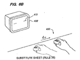
「背景技術」のセクションで述べたとおり、自由空間ポインタとして動作するリモートデバイスが、本明細書の特別な関心対象である。そのようなデバイスは、動き、例えば、ジェスチャを、ユーザインタフェースに対するコマンドに変換することを可能にする。例示的な自由空間ポインティングデバイス400が、図3に示されている。図3では、自由空間ポインティングのユーザの動きが、例えば、自由空間ポインティングデバイス400のx軸姿勢(ロール)モーション、y軸エレベーション(ピッチ)モーション、および/またはz軸方位(ヨー)モーションの組み合わせに関して定義されることが可能である。加えて、本発明の一部の例示的な実施形態は、x軸、y軸、およびz軸に沿った自由空間ポインティングデバイス400の直線の動きを測定して、カーソルの動き、または他のユーザインタフェースコマンドを生成することもできる。図3の例示的な実施形態では、自由空間ポインティングデバイス400は、2つのボタン402および404、ならびにスクロールホイール406を含むが、他の例示的な諸実施形態は、他の物理的構成を含む。本発明の例示的な諸実施形態によれば、自由空間ポインティングデバイス400は、ディスプレイ408の前方でユーザによって把持され、自由空間ポインティングデバイス400の動きが、自由空間ポインティングデバイスによって、例えば、ディスプレイ408上のカーソル410を動かすように、ディスプレイ408上で表示される情報と対話するのに使用可能な出力に変換されるものと予期される。例えば、y軸を中心とする自由空間ポインティングデバイス400の回転が、自由空間ポインティングデバイス400によって感知されて、ディスプレイ408のy2軸に沿ってカーソル410を動かすようにシステムが使用できる出力に変換されることが可能である。同様に、z軸を中心とする自由空間ポインティングデバイス408の回転が、自由空間ポインティングデバイス400によって感知されて、ディスプレイ408のx2軸に沿ってカーソル410を動かすようにシステムが使用できる出力に変換されることが可能である。自由空間ポインティングデバイス400の出力は、カーソルの動き以外(またはそれに加えて)のいくつかの形で、ディスプレイ408と対話するのに使用されることが可能であり、例えば、出力は、カーソルフェージング、音量、またはメディアトランスポート(再生、一時停止、早送り、および巻き戻し)を制御することができることが理解されよう。入力コマンドは、カーソルの動きに加えて、操作、例えば、ディスプレイの特定の領域に対するズームインまたはズームアウトを含むことが可能である。カーソルは、可視であっても、可視でなくてもよい。同様に、自由空間ポインティングデバイス400のx軸を中心として感知される自由空間ポインティングデバイス400の回転が、y軸回転および/またはz軸回転に加えて、またはそれらの回転の代替として使用されて、ユーザインタフェースに入力を与えることも可能である。
As mentioned in the “Background” section, remote devices operating as free space pointers are of particular interest herein. Such a device makes it possible to translate movements, eg gestures, into commands for the user interface. An exemplary free
本発明の1つの例示的な実施形態によれば、2つの回転センサ502および504、ならびに1つの加速度計506が、図4に示されるとおり、自由空間ポインティングデバイス400内のセンサ群として使用されることが可能である。回転センサ502および504は、例えば、アナログデバイシーズによって製造されるADXRS150センサまたはADXRS401センサを使用して実施されることが可能である。他のタイプの回転センサも、回転センサ502および504として使用されることが可能であり、ADXRS150およびADXRS401は、単に例示的な例として使用されていることが当業者には理解されよう。従来のジャイロスコープとは異なり、これらの回転センサは、MEMS技術を使用して、1方向に沿ってだけ共鳴することが可能なようにフレームに取り付けられた共鳴する質量をもたらす。共鳴する質量は、センサが固定された筐体が、センサの感知軸を中心に回転させられると、ずれる。そのずれが、コリオリの加速効果を使用して測定されて、感知軸に沿った回転に関連する角速度が算出されることが可能である。回転センサ502および504が、単一の感知軸を有する(例えば、ADXRS150のように)場合、センサ502および504は、センサ502および504の感知軸が、測定されるべき回転と揃えられるように自由空間ポインティングデバイス400内に装着されることが可能である。本発明のこの例示的な実施形態の場合、このことは、図4に示されるとおり、回転センサ504は、センサ504の感知軸がy軸と平行になるように装着され、回転センサ502は、センサ502の感知軸がz軸と平行になるように装着されることを意味する。しかし、回転センサ502および504の感知軸を、所望される測定軸と平行になるように揃えることは、本発明の例示的な諸実施形態が、軸間のオフセットを補償するための技術も提供するので、要求されないことに留意されたい。
According to one exemplary embodiment of the present invention, two
本発明による例示的な自由空間ポインティングデバイス400を実施する際に直面する1つの課題は、あまりにも高価ではない一方で、自由空間ポインティングデバイス400の動き、ユーザインタフェースが、自由空間ポインティングデバイスのその特定の動きにどのように反応するかに関するユーザの期待、およびその動きに応答する実際のユーザインタフェースパフォーマンスの間における高い度合いの相互関係をもたらすコンポーネント、例えば、回転センサ502および504を使用することである。例えば、自由空間ポインティングデバイス400が動いていない場合、ユーザは、カーソルがスクリーン上をドリフトすべきではないと期待する可能性が高い。同様に、ユーザが、自由空間ポインティングデバイス400を、純粋にy軸を中心に回転させた場合、ユーザは、ディスプレイ408上のもたらされるカーソルの動きが、有意なx2軸成分は全く含むことを期待しない可能性が高い。本発明の例示的な諸実施形態の以上、およびその他の態様を実現するのに、様々な測定および計算が、ハンドヘルドデバイス400によって実行され、それらの測定および計算は、センサ502、504、および506の1つまたは複数の出力を調整するのに、かつ/またはプロセッサによって入力の一部として使用されて、センサ502、504、および506の出力に基づき、ユーザインタフェースに関する適切な出力が算出される。それらの測定および計算は、広くは、以下の2つのカテゴリに入る要因を補償するのに使用される。すなわち、(1)自由空間ポインティングデバイス400に固有の要因、例えば、デバイス400内で使用される特定のセンサ502、504、および506に関連する誤差、またはデバイス400内にセンサが装着されている仕方に関連する誤差、および(2)自由空間ポインティングデバイス400に固有ではなく、代わりに、ユーザが、自由空間ポインティングデバイス400を使用する仕方、例えば、直線加速度、傾き、および微動に関連する要因である。それらの効果のそれぞれに対処するための例示的な技術を以下に説明する。
One challenge faced in implementing an exemplary free
本発明の例示的な諸実施形態による自由空間ポインティングデバイスの一般的な動作を説明するプロセスモデル600が、図5に示されている。回転センサ502および504、ならびに加速度計506は、周期的に、例えば、毎秒200サンプル、サンプリングされるアナログ信号を生成する。この説明では、それらの入力のセットは、(x,y,z,ay,az)という表記を使用して示され、x、y、zは、x軸方向、y軸方向、およびz軸方向における自由空間ポインティングデバイスの加速にそれぞれ関連する例示的な3軸加速度計506のサンプリングされた出力値であり、ayは、y軸を中心とする自由空間ポインティングデバイスの回転に関連する回転センサ502からのサンプリングされた出力値であり、azは、z軸を中心とする自由空間ポインティングデバイス400の回転に関連する回転センサ504からのサンプリングされた出力値である。
A
加速度計506からの出力がもたらされ、加速度計506が、アナログ出力をもたらす場合、その出力は、A/D変換器(図示せず)によってサンプリングされ、デジタル化されて、サンプリングされた加速度計出力602が生成される。サンプリングされた出力値は、変換ファンクション604によって示されるとおり、生の単位から、加速度の単位に、例えば、重力加速度(g)に変換される。加速度較正ブロック606が、変換ファンクション604のために使用される値をもたらす。加速度計出力602のこの較正には、例えば、加速度計506に関連するスケール誤差、オフセット誤差、および軸合わせ不良誤差の1つまたは複数の補償が含まれることが可能である。加速度計データの例示的な補償は、以下の数式を使用して実行されることが可能である。すなわち、
A=S*((M-P).*G(T)) (1)
ただし、Mは、サンプリングされた出力値(x,y,z)から成る3×1列ベクトルであり、Pは、センサオフセットの3×1列ベクトルであり、Sは、スケール補償、軸合わせ不良補償とセンサ回転補償をともに含む3×3行列である。G(T)は、温度の関数である利得係数である。「*」演算子は、行列乗算を表し、「.*」演算子は、要素乗算を表す。例示的な加速度計506は、+/-2gという例示的な最大範囲を有する。センサオフセット、Pは、0gの加速度計測定値の場合のセンサ出力、M指す。スケールは、サンプリングされた単位値とgの間の変換係数を指す。任意の所与の加速度計センサの実際のスケールは、例えば、製造のばらつきに起因して、それらの公称のスケール値からずれる可能性がある。したがって、前述の数式におけるスケール係数は、その偏差に比例する。
If the output from the
A = S * ((MP). * G (T)) (1)
Where M is a 3 × 1 column vector consisting of sampled output values (x, y, z), P is a 3 × 1 column vector of sensor offsets, and S is scale compensation or misalignment A 3x3 matrix that includes both compensation and sensor rotation compensation. G (T) is a gain coefficient that is a function of temperature. The “ * ” operator represents matrix multiplication, and the “. * ” Operator represents element multiplication. The
加速度計506のスケール偏差およびオフセット偏差は、例えば、1gの力を1つの軸に沿って加え、結果、R1を測定することによって測定されることが可能である。次に、1gの力が加えられて、測定値R2がもたらされる。個別の軸スケール、s、および個別の軸オフセット、pは、以下のとおり計算されることが可能である。すなわち、
s=(R1-R2)/2 (2)
p=(R1+R2)/2 (3)
この単純なケースでは、Pは、各軸に関するpの列ベクトルであり、Sは、各軸に関する1/sの対角行列である。
The scale deviation and offset deviation of the
s = (R1-R2) / 2 (2)
p = (R1 + R2) / 2 (3)
In this simple case, P is a column vector of p for each axis, and S is a 1 / s diagonal matrix for each axis.
しかし、スケールおよびオフセットに加えて、加速度計506によって生成される読み取り値は、交差軸効果を被る可能性もある。交差軸効果には、例えば、加速度計506が自由空間ポインティングデバイス400内に装着された際に、加速度計506の感知軸の1つまたは複数が、慣性基準フレームにおける対応する軸と揃えられていない、合わせ不良の軸、または、例えば、軸は適切に揃えられているものの、純粋にy軸の加速力により、加速度計506のz軸に沿ったセンサ読み取り値がもたらされる可能性がある、加速度計506自体の機械加工に関連する機械的誤差が含まれる。以上の効果の両方とも、やはり、測定され、ファンクション606によって実行される較正に加えられることが可能である。
However, in addition to scale and offset, the readings generated by the
加速度計506は、本発明の例示的な諸実施形態による例示的な自由空間ポインティングデバイスにおいていくつかの目的を果たす。例えば、回転センサ502および504が、前述した例示的なコリオリ効果回転センサを使用して実施される場合、回転センサ502および504の出力は、各回転センサによって経験される直線加速度に基づいて異なる。このため、加速度計506の1つの例示的な使用は、直線加速度の違いによって生じさせられる、回転センサ502および504によって生成される読み取り値の変動を補償することである。これは、変換された加速度計読み取り値に利得行列610を掛けて、その結果から(またはその結果に)、対応するサンプリングされた回転センサデータ612を引くこと(または足すこと)によって達せられることが可能である。例えば、回転センサ502からのサンプリングされた回転データayが、ブロック614で、以下のとおり、直線加速度に関して補償されることが可能である。すなわち、
αy'=αy-C*A (4)
ただし、Cは、単位数/gで与えられる各軸に沿った直線加速度に対する回転センサ感受性の1×3行ベクトルであり、Aは、較正された直線加速度である。同様に、回転センサ504からのサンプリングされた回転データazに関する直線加速度補償が、ブロック614でもたらされることが可能である。利得行列、Cは、製造上の違いに起因して、回転センサの間で異なる。Cは、多くの回転センサに関する平均値を使用して計算されてもよく、あるいは各回転センサに関してカスタム計算されてもよい。
The
αy '= αy-C * A (4)
Where C is a 1 × 3 row vector of rotation sensor sensitivity to linear acceleration along each axis given in units / g, and A is a calibrated linear acceleration. Similarly, linear acceleration compensation for sampled rotation data az from
加速度計データと同様に、サンプリングされた回転データ612は、次に、ファンクション616において、サンプリングされた単位値から、角回転の速度に、例えば、ラジアン/秒に関連する値に変換される。また、この変換ステップは、サンプリングされた回転データを、例えば、スケールおよびオフセットに関して、補償するファンクション618によってもたらされる較正を含むことも可能である。ayとazの両方に関する変換/較正は、例えば、以下の数式を使用して達せられることが可能である。すなわち、
αrad/秒=(α'-offset(T))*scale+dOffset (5)
ただし、α'は、変換/較正される値を指し、offset(T)は、温度に関連するオフセット値を指し、scaleは、サンプリングされた単位値とラジアン/秒の間の変換係数を指し、dOffsetは、動的なオフセット値を指す。数式(5)は、行列式として実施されてもよく、その場合、scaleを除き、すべての変数はベクトルである。行列式の形態では、scaleは、軸合わせ不良および回転オフセット係数を補正する。これらの変数のそれぞれについて、以下により詳細に説明する。
Similar to the accelerometer data, the sampled
αrad / sec = (α'-offset (T)) * scale + dOffset (5)
Where α ′ refers to the value to be converted / calibrated, offset (T) refers to the temperature related offset value, scale refers to the conversion factor between the sampled unit value and radians / second, dOffset refers to a dynamic offset value. Equation (5) may be implemented as a determinant, in which case all variables are vectors except scale. In the determinant form, scale corrects misalignment and rotational offset coefficients. Each of these variables is described in more detail below.
オフセット値、offset(T)およびdOffsetは、いくつかの異なる形で算出されることが可能である。自由空間ポインティングデバイス400が、例えば、y軸方向で回転されていない場合、センサ502は、オフセット値を出力するはずである。しかし、そのオフセットは、温度によって非常に影響されている可能性があり、したがって、このオフセット値は、変動する可能性が高い。オフセット温度較正が、工場において実行されることが可能であり、その場合、offset(T)の値は、ハンドヘルドデバイス400に事前にプログラミングされることが可能であり、あるいは代替的に、オフセット温度較正は、デバイスの寿命中に動的に学習されることも可能である。動的オフセット補償を達するのに、温度センサ619からの入力が、回転較正ファンクション618において使用されて、offset(T)の現在の値が計算される。offset(T)パラメータは、センサ読み取り値からオフセットバイアスの大半を取り除く。しかし、0の動きにおいてほぼすべてのカーソルドリフトを無効にすることが、高性能のポインティングデバイスをもたらすのに役立つ可能性がある。したがって、追加の係数、dOffsetが、自由空間ポインティングデバイス400が使用されている間に、動的に計算されることが可能である。静止検出ファンクション608が、ハンドヘルドが静止している可能性が高い場合、およびオフセットが再計算されなければならない場合を判定する。したがって、静止検出ファンクション608を実施するための例示的な技術、および用法を以下に説明する。
The offset value, offset (T) and dOffset can be calculated in several different ways. If the free
dOffset計算の例示的な実施は、ローパスフィルタリングされた較正済みのセンサ出力を使用する。静止出力検出ファンクション608は、例えば、ローパスフィルタ出力の平均値の計算をトリガする指示を回転較正ファンクション618に与える。また、静止出力検出ファンクション608は、新たに計算された平均値が、dOffsetの既存の値にいつ繰り込まれるかも制御することができる。多数の異なる技術が、dOffsetの既存の値、および単純平均、ローパスフィルタリング、およびカルマンフィルタリングを含むが、以上には限定されない新たな平均から、dOffsetの新たな値を計算するために使用されることが可能であることが、当業者には認識されよう。さらに、回転センサ502および504のオフセット補償に関する多数の変種が使用されることが可能であることも、当業者には認識されよう。例えば、offset(T)ファンクションは、定数値(例えば、温度で変化しない)を有することが可能であり、2つより多くのオフセット補償値が、使用されることが可能であり、かつ/または単一のオフセット値だけが、オフセット補償のために計算/使用されることが可能である。
An exemplary implementation of the dOffset calculation uses a low-pass filtered calibrated sensor output. The stationary
ブロック616における変換/較正の後、ファンクション620において、回転センサ502および504からの入力は、それらの入力を回転させて、慣性基準フレームに入れるように、すなわち、ユーザが自由空間ポインティングデバイス400を把持している仕方に関連する傾きを補償するように、さらに処理されることが可能である。傾き補正は、本発明による自由空間ポインティングデバイスの使用パターンの違いを補償するように意図されているので、本発明の一部の例示的な諸実施形態の別の重要な態様である。より具体的には、本発明の例示的な諸実施形態による傾き補償は、複数のユーザが、異なるx軸回転位置でポインティングデバイスを手に把持するが、自由空間ポインティングデバイス400内の回転センサ502および504の感知軸は、固定であるという事実を補償することを意図している。ディスプレイ408上のカーソルの並進は、ユーザが自由空間ポインティングデバイス400を握る仕方に実質的に左右されない、例えば、ユーザが自由空間ポインティングデバイス400を把持している向きにかかわらず、ディスプレイ508の水平の次元(x2軸)におおむね対応する形で行き来するように自由空間ポインティングデバイス400を回転させることは、x2軸に沿ったカーソルの並進をもたらすべきであるのに対して、ディスプレイ508の垂直の次元(y2軸)におおむね対応する形で上下するように自由空間ポインティングデバイスを回転させることは、y2軸に沿ったカーソルの並進をもたらすべきであることが望ましい。
After transformation / calibration in
本発明の例示的な諸実施形態による傾き補償の必要性をよりよく理解するため、図6(a)に示された例を考慮されたい。図6(a)では、ユーザは、0度のx軸回転値を有するものとして定義されることが可能な、例示的な慣性基準フレームにおいて自由空間ポインティングデバイス400を把持している。慣性基準フレームは、単に例として、図6(a)に示された向きに対応することが可能であり、あるいは他の任意の向きとして定義されることが可能である。y軸方向またはz軸方向における自由空間ポインティングデバイス400の回転は、回転センサ502および504によってそれぞれ感知される。例えば、図6(b)に示される、量Δzだけのz軸を中心とした自由空間ポインティングデバイス400の回転は、ディスプレイ408上のx2軸次元における対応するカーソルの並進、Δx2(すなわち、カーソル410の破線バージョンと破線でないバージョンの間の距離)をもたらす。
To better understand the need for slope compensation according to exemplary embodiments of the present invention, consider the example shown in FIG. 6 (a). In FIG. 6 (a), the user is holding the free
他方、ユーザが、自由空間ポインティングデバイス400を異なる向きで、例えば、慣性基準フレームに対していくらかの量のx軸回転で把持した場合、センサ502および504によってもたらされる情報は、ユーザによって意図されるインタフェースアクションの正確な表現をもたらさない(傾き補償がない)。例えば、図6(c)を参照して、ユーザが、図6(a)に示されるとおり、例示的な慣性基準フレームに対して45度のx軸回転で自由空間ポインティングデバイス400を把持する状況を考慮されたい。ユーザによる同一のz軸回転Δzを想定すると、カーソル410は、図6(d)で示されるとおり、代わりに、x2軸方向とy2軸方向の両方で並進させられる。これは、回転センサ502の感知軸が、現時点で、y軸とz軸の間の向きにされている(ユーザの手の中のデバイスの向きのため)という事実に起因する。同様に、回転センサ504の感知軸もまた、y軸とz軸の間の向きにされている(ただし、異なる象限における)。自由空間ポインティングデバイス400がどのように把持されているかに関してユーザにトランスペアレントなインタフェースを提供するため、本発明の例示的な諸実施形態による傾き補償は、回転センサ502および504から出力された読み取り値を、それらのセンサからの読み取り値を処理して、自由空間ポインティングデバイス400の回転モーションを示す情報にすることの一環として、変換して慣性基準フレームに戻す。
On the other hand, if the user grips the free
本発明の例示的な諸実施形態によれば、図5に戻ると、以上のことは、ファンクション622において、加速度計506から受け取られる入力yおよび入力zを使用して自由空間ポインティングデバイス400の傾きを算出することにより、達せられることが可能である。より具体的には、加速度データは、前述したとおり、変換され、較正された後、LPF624においてローパスフィルタリングされて、平均加速度(重力加速度)値を傾き算出ファンクション622に与えることが可能である。次に、傾きθが、ファンクション622において以下のとおり計算されることが可能である。すなわち、
According to exemplary embodiments of the present invention, returning to FIG. 5, the above is the tilt of free

値θは、0による除算を防止するようにatan2(y,z)として数値的に計算されて、正しい符号を与えることが可能である。次に、ファンクション620が、以下の数式を使用して、変換/較正済みの入力αyおよびαzの回転Rを実行して、 The value θ can be calculated numerically as atan2 (y, z) to prevent division by 0 and give the correct sign. Next, function 620 performs a rotation R of the transformed / calibrated inputs αy and αz using the following equation:
変換/較正済みの入力αyおよびαzを回転させて、傾きθを補償することができる。この例示的な実施形態において説明される傾き補償は、筐体基準フレームからのセンサ読み取り値をユーザの基準フレームに変換するためのより一般的な技術のサブセットであり、それらの技術は、「Free Space Pointing Devices with Tilt Compensation and Improved Usability」という名称の、前段で参照により組み込まれた特許出願でさらに説明されている。 The transformed / calibrated inputs αy and αz can be rotated to compensate for the slope θ. The tilt compensation described in this exemplary embodiment is a subset of a more general technique for converting sensor readings from a housing reference frame to a user's reference frame, which techniques are described as “Free This is further explained in the patent application entitled “Space Pointing Devices with Tilt Compensation and Improved Usability”, incorporated by reference in the preceding paragraph.
較正済みのセンサ読み取り値が、直線加速度に関して補償され、自由空間ポインティングデバイス400の角回転を示す読み取り値になるように処理され、傾きに関して補償されると、ブロック626および628で後処理が実行されることが可能である。例示的な後処理には、人間の微動などの様々な要因の補償が含まれることが可能である。微動は、いくつかの異なる方法を使用して除去されることが可能であるが、微動を除去する1つのやり方は、ヒステリシスを使用することによる。回転ファンクション620によってもたらされた角速度が、角位置をもたらすように組み込まれる。較正された大きさのヒステリシスが、次に、角位置に適用される。ヒステリシスブロックの出力の微分が行われて、角速度が再びもたらされる。結果の出力が、次に、ファンクション628においてスケーリングされて(例えば、サンプリング周期に基づき)、インタフェース内の結果、例えば、ディスプレイ408上のカーソル410の動きを生じさせるのに使用される。
Once the calibrated sensor reading is compensated for linear acceleration and processed to be a reading indicative of the angular rotation of the free
本発明による例示的な自由空間ポインティングデバイスのプロセス説明を提供したので、図7は、例示的なハードウェアアーキテクチャを示す。図7では、プロセッサ800が、スクロールホイール802、JTAG804、LED806、スイッチマトリックス808、IR光検出器810、回転センサ812、加速度計814、およびトランシーバ816を含む、自由空間ポインティングデバイスの他の要素と通信する。スクロールホイール802は、ユーザが、スクロールホイール802を時計方向に、または反時計方向に回転させることによってインタフェースに入力を与えることを可能にするオプションの入力コンポーネントである。JTAG804は、プログラミング‐デバッグインタフェースをプロセッサに与える。LED806は、例えば、ボタンが押されると、視覚的フィードバックをユーザに与える。スイッチマトリックス808は、入力、例えば、自由空間ポインティングデバイス400上のボタンが押し下げられた、または解放されたという指示を受け取り、それらの入力は、次に、プロセッサ800に転送される。例示的な自由空間ポインティングデバイスが、他のリモコンからのIRコードを知ることを可能にするオプションのIR光検出器810が、提供されることが可能である。回転センサ812は、例えば、前述したとおり、自由空間ポインティングデバイスのy軸回転およびz軸回転に関する読み取り値をプロセッサ800に与える。加速度計814は、例えば、傾き補償を実行し、直線加速度が、回転センサ812によって生成される回転読み取り値に導入する誤差を補償するように、前述したとおり使用されることが可能な、自由空間ポインティングデバイス400の直線加速度に関する読み取り値をプロセッサ800に与える。トランシーバ816が、自由空間ポインティングデバイス400との間で、例えば、システムコントローラ228に、またはコンピュータに関連するプロセッサに情報を通信するのに使用される。トランシーバ816は、例えば、短距離無線通信のためにBluetooth標準に準拠して動作する無線トランシーバ、または赤外線トランシーバであることが可能である。代替的に、自由空間ポインティングデバイス400は、有線接続を介してシステムと通信することもできる。
Having provided a process description of an exemplary free space pointing device according to the present invention, FIG. 7 illustrates an exemplary hardware architecture. In FIG. 7,
図4の例示的な実施形態では、自由空間ポインティングデバイス400は、2つの回転センサ502および504、ならびに加速度計506を含む。しかし、本発明の別の実施形態によれば、自由空間ポインティングデバイスは、代替的に、例えば、z軸方向の角速度を測定するための1つだけの回転センサと、加速度計とを含むことも可能である。そのような例示的な実施形態の場合、前述したのと同様の機能が、加速度計を使用して、回転センサによって感知されない軸に沿った角速度を測定することによって提供されることが可能である。例えば、y軸を中心とする回転速度は、加速度計によって生成されたデータを使用し、以下を計算して、計算されることが可能である。すなわち、
In the exemplary embodiment of FIG. 4, free
加えて、回転センサによって測定されない寄生加速度効果も、除去されなければならない。それらの効果には、実際の直線加速度、回転速度および回転加速度に起因して測定された加速度、および人間の微動に起因する加速度が含まれる。 In addition, parasitic acceleration effects that are not measured by the rotation sensor must also be removed. These effects include actual linear acceleration, rotational speed and acceleration measured due to rotational acceleration, and acceleration due to human tremors.
簡単に前述したとおり、静止検出ファンクション608は、自由空間ポインティングデバイス400が、例えば、静止しているか、またはアクティブである(動いている)かを判定するように動作することができる。この分類は、いくつかの異なる仕方で実行されることが可能である。1つの仕方は、本発明の例示的な実施形態によれば、所定のウインドウ、例えば、毎1/4秒にわたって、すべての入力(x,y,z,αy,αz)のサンプリングされた入力データの分散を計算することである。その分散が、次に、閾値と比較されて、自由空間ポインティングデバイスが、静止している、またはアクティブであると分類される。
As briefly described above, the
本発明の例示的な諸実施形態による別の静止検出技術には、例えば、入力データに高速フーリエ変換(FFT)を実行することにより、入力を周波数ドメインに変換することがかかわる。次に、そのデータが、例えば、ピーク検出方法を使用して分析されて、自由空間ポインティングデバイス400が静止しているか、またはアクティブであるかが判定されることが可能である。さらに、第3のカテゴリ、具体的には、ユーザが、自由空間ポインティングデバイス400を把持しているが、デバイス400を動かしていないケース(本明細書では、「安定した」状態とも呼ばれる)が、区別されることが可能である。この第3のカテゴリは、自由空間ポインティングデバイス400がユーザによって把持されている場合にユーザの手の微動によって導入される、自由空間ポインティングデバイス400の小さい動きを検出することにより、静止(把持されていない)およびアクティブから区別されることが可能である。また、ピーク検出も、この判定を行うのに、静止検出ファンクション608によって使用されることが可能である。人間の微動周波数の範囲内、例えば、公称で8〜12Hzの範囲内のピークは、通常、およそ20dBだけ、デバイスの雑音フロア(デバイスが静止しており、把持されていない場合に生じる)を超える。
Another stationary detection technique according to exemplary embodiments of the invention involves converting the input to the frequency domain, for example, by performing a Fast Fourier Transform (FFT) on the input data. The data can then be analyzed using, for example, a peak detection method to determine whether the free
以上の例では、周波数ドメインの変動が、特定の周波数範囲内で検出されたが、監視され、自由空間ポインティングデバイス400のステータスを特徴付けるのに使用される実際の周波数範囲は、様々である可能性がある。例えば、公称の微動周波数範囲は、例えば、自由空間ポインティングデバイス400のエルゴノミクスおよび重量に基づき、例えば、8〜12Hzから4〜7Hzに移る可能性がある。
In the above example, frequency domain variations were detected within a specific frequency range, but the actual frequency range that is monitored and used to characterize the status of the free
本発明の別の例示的な実施形態によれば、静止検出機構608は、状態マシンを含むことが可能である。例示的な状態マシンが、図8に示されている。図8では、ACTIVE状態が、この実施例では、自由空間ポインティングデバイス400が動いており、例えば、ユーザインタフェースに入力を与えるのに使用されている間の既定の状態である。自由空間ポインティングデバイス400は、リセット入力によって示されるデバイスの起動時に、ACTIVE状態に入る。自由空間ポインティングデバイス400は、動くのを止めた場合、INACTIVE状態に入ることが可能である。図8に示される様々な状態遷移が、回転センサ502と回転センサ504のいずれか、または両方から出力されたデータ、加速度計506から出力されたデータ、時間ドメインデータ、周波数ドメインデータ、または以上の任意の組み合わせを含むが、以上には限定されない、いくつかの異なる基準のいずれかによってトリガされることが可能である。状態遷移条件は、「ConditionstateA→stateB」という規約を使用して、本明細書で一般的に示される。例えば、自由空間ポインティングデバイス400は、conditionactive→inactiveが生じると、ACTIVE状態からINACTIVE状態に遷移する。単に例示のため、conditionactive→inactiveは、例示的な自由空間ポインティングデバイス400では、回転センサと加速度計の両方からの平均偏差値および/または標準偏差値が、第1の所定の期間にわたって第1の所定の閾値を下回って低下した場合に生じるものと考慮されたい。ACTIVE状態にある場合、モーションセンサ(例えば、回転センサおよび/または加速度計)から受け取られたデータは、線形フィルタリング、カルマンフィルタリング、カルマン平滑化、状態空間推定、期待値最大化、またはその他のモデルベースの技術などの、1つまたは複数の処理技術を使用して、ユーザによって導入された意図的な動きに関連する第1のデータと、ユーザによって導入された意図的でない動き(微動)に関連する第2のデータに分けられることが可能である。第1のデータは、次に、ハンドヘルドデバイスの意図される動き(例えば、カーソルの動きをサポートする)に関連する出力を生成するようにさらに処理されることが可能であるのに対して、第2のデータは、以下により詳細に説明するとおり、例えば、ユーザ識別のために、微動入力として使用されることが可能である。
According to another exemplary embodiment of the present invention,
状態遷移は、解釈されたセンサ出力に基づく、いくつかの異なる条件によって判定されることが可能である。例示的な条件メトリックは、時間ウインドウにわたる解釈された信号の変動、基準値と、時間ウインドウにわたる解釈された信号との間の閾値、基準値と、時間ウインドウにわたるフィルタリング済みの解釈された信号との間の閾値が含まれ、基準値と、開始時からの解釈された信号との間の閾値が、状態遷移を判定するのに使用されることが可能である。以上の条件メトリックのすべて、または任意の組み合わせが、状態遷移をトリガするのに使用されることが可能である。代替的に、他のメトリックも使用されることが可能である。本発明の1つの例示的な実施形態によれば、INACTIVE状態からACTIVE状態への遷移は、(1)時間ウインドウにわたるセンサ出力の平均値が、所定の閾値より大きい場合、または(2)時間ウインドウにわたるセンサ出力の値の変動が、所定の閾値より大きい場合、または(3)センサ値の間の瞬間デルタが、所定の閾値より大きい場合に生じる。 State transitions can be determined by several different conditions based on the interpreted sensor output. Exemplary conditional metrics are: interpreted signal variation over time window, threshold between reference value and interpreted signal over time window, reference value and filtered interpreted signal over time window The threshold between the reference value and the interpreted signal from the start can be used to determine the state transition. All or any combination of the above conditional metrics can be used to trigger a state transition. Alternatively, other metrics can be used. According to one exemplary embodiment of the present invention, the transition from the ACTIVE state to the ACTIVE state may occur when (1) the average value of the sensor output over the time window is greater than a predetermined threshold, or (2) the time window. Occurs when the sensor output value variation over time is greater than a predetermined threshold, or (3) the instantaneous delta between sensor values is greater than a predetermined threshold.
INACTIVE状態は、自由空間ポインティングデバイス400が依然、使用されている、例えば、1/10秒のオーダの、短い休止と、安定した条件または静止条件への実際の遷移とを、静止検出機構608が区別することを可能にする。これにより、以下に説明するSTABLE状態中、およびSTATIONARY状態中に実行されるファンクションが、自由空間ポインティングデバイスが使用されている間に、意図せずに実行されることが防止される。自由空間ポインティングデバイス400は、conditionactive→inactiveが生じた場合、例えば、自由空間ポインティングデバイス400が、再び動くことを始めて、回転センサおよび加速度計からの測定された出力が、INACTIVE状態で第2の所定の期間が経過する前に第1の閾値を超えた場合、ACTIVE状態に戻るように遷移する。
The INACTIVE state indicates that the free-
自由空間ポインティングデバイス400は、第2の所定の期間が経過した後、STABLE状態またはSTATIONARY状態に遷移する。前述したとおり、STABLE状態は、人によって把持されているが、実質的に動いていないという自由空間ポインティングデバイス400の特徴付けを反映する一方で、STATIONARY状態は、人によって把持されていないという自由空間ポインティングデバイスの特徴付けを反映する。このため、本発明による例示的な状態マシンは、手の微動に関連する最小の動きが存在する場合、第2の所定の期間が経過した後に、STABLE状態への遷移を可能にし、さもなければ、STATIONARY状態への遷移を可能にすることができる。
The free
STABLE状態およびSTATIONARY状態は、自由空間ポインティングデバイス400が、様々なファンクションを実行することができる時間を定義する。例えば、STABLE状態は、ユーザが、自由空間ポインティングデバイス400を把持しているが、デバイス400を動かしていない時間を反映することを意図しているので、デバイスは、自由空間ポインティングデバイス400がSTABLE状態にある間の、自由空間ポインティングデバイス400の動きを、例えば、回転センサおよび/または加速度計からの出力を、STABLE状態にある最中に格納することにより、記録することができる。それらの格納された測定値は、以下に説明するとおり、特定のユーザまたはユーザらに関連する微動パターンを判定するのに使用されることが可能である。同様に、STATIONARY状態にある間、自由空間ポインティングデバイス400は、前述したとおり、オフセットを補償する際に使用するために、回転センサおよび/または加速度計からの読み取り値を得ることができる。
The STABLE state and the STATIONARY state define times during which the free
自由空間ポインティングデバイス400が、STABLE状態またはSTATIONARY状態にある間に、動くことを始めた場合、これにより、ACTIVE状態に戻ることがトリガされることが可能である。さもなければ、測定が行われた後、デバイスは、SLEEP状態に遷移することができる。スリープ状態にある間、デバイスは、自由空間ポインティングデバイスの電力消費量が低減され、例えば、回転センサおよび/または加速度計のサンプリングレートも低減されるパワーダウンモードに入ることができる。また、SLEEP状態には、外部コマンドを介して入ることも可能であり、したがって、ユーザ、または別のデバイスが、SLEEP状態に入るよう自由空間ポインティングデバイス400に命令することができる。
If the free
別のコマンドを受け取ると、または自由空間ポインティングデバイス400が動くことを始めると、デバイスは、SLEEP状態からWAKEUP状態に遷移することができる。INACTIVE状態と同様に、WAKEUP状態は、ACTIVE状態への遷移が妥当であること、例えば、自由空間ポインティングデバイス400が、意図せずに突き動かされていないことをデバイスが確認する機会を提供する。
When another command is received or the free
状態遷移のための諸条件は、対称的であっても、異なってもよい。このため、conditionactive→inactiveに関連する閾値は、conditioninactive→activeに関連する閾値と同一である(または異なる)ことが可能である。これにより、本発明による自由空間ポインティングデバイスが、ユーザ入力をより正確にキャプチャすることが可能になる。例えば、状態マシンインプリメンテーションを含む例示的な諸実施形態は、とりわけ、静止条件に入る遷移に関する閾値が、静止条件から出る遷移に関する閾値とは異なることを許す。 Conditions for the state transition may be symmetric or different. Thus, the threshold associated with condition active → inactive can be the same (or different) as the threshold associated with condition inactive → active . This allows the free space pointing device according to the present invention to capture user input more accurately. For example, exemplary embodiments including a state machine implementation allow, among other things, the threshold for transitions entering a quiescent condition to be different from the threshold for transitions exiting from a quiescent condition.
ある状態に入ること、またはある状態を離れることは、他のデバイスファンクションをトリガするのに使用されることも可能である。例えば、ユーザインタフェースが、任意の状態からACTIVE状態への遷移に基づいて起動されることが可能である。逆に、自由空間ポインティングデバイスおよび/またはユーザインタフェースが、ACTIVEまたはSTABLEからSTATIONARYまたはINACTIVEに自由空間ポインティングデバイスが遷移すると、オフにされる(またはスリープモードに入る)ことも可能である。代替的に、カーソル410が、自由空間ポインティングデバイス400の静止状態からの遷移、または静止状態への遷移に基づき、表示されること、またはスクリーンから除去されることも可能である。
Entering or leaving a state can also be used to trigger other device functions. For example, the user interface can be activated based on a transition from any state to the ACTIVE state. Conversely, the free space pointing device and / or user interface may be turned off (or enter sleep mode) when the free space pointing device transitions from ACTIVE or STABLE to STATIONARY or INACTIVE. Alternatively, the
(微動)
前述したとおり、ハンドヘルドデバイスがSTABLE状態にある期間は、例えば、特定のユーザに関連する微動データを記憶するのに使用されることが可能である。通常、各ユーザは、異なる微動パターンを示す。本発明の例示的な諸実施形態によれば、ユーザ微動のその特性を使用して、ユーザ側の他のアクション(例えば、パスワードを入力すること)を全く要求せずに、いずれのユーザが、ハンドヘルドデバイスを現在、把持しているかを識別することができる。例えば、ユーザの微動パターンは、ユーザが、例えば、10秒間、可能な限りしっかりと自由空間ポインティングデバイスを把持するように要求される初期手続き中に、ハンドヘルドまたはシステムによって記憶されることが可能である(自由空間ポインティングデバイス400の中に格納されるか、またはシステムに伝送される)。
(Fine)
As described above, the time period during which the handheld device is in the STABLE state can be used, for example, to store tremor data associated with a particular user. Normally, each user shows a different fine movement pattern. According to exemplary embodiments of the present invention, any user can use that property of user tremor to request no other action on the part of the user (e.g., enter a password) It can be identified whether the handheld device is currently gripped. For example, the user's tremor pattern can be stored by the handheld or system during an initial procedure where the user is required to hold the free space pointing device as firmly as possible, for example, for 10 seconds. (Stored in free
このパターンは、様々なユーザインタフェース機能を実行するユーザの固有の(または準固有の)シグネチャとして使用されることが可能である。例えば、ユーザインタフェースおよび/またはハンドヘルドデバイスは、現在の微動パターンをメモリの中に格納されているパターンと比較することにより、一群のユーザから、例えば、家族から、ユーザを識別することができる。この識別は、その後、例えば、その識別されたユーザに関連する選好設定を取り出すのに使用されることが可能である。例えば、自由空間ポインティングデバイスが、前段で参照により組み込まれた特許出願で説明されるメディアシステムと一緒に使用される場合、システムが、微動パターン比較を介してユーザを認識した後、そのユーザに関連するメディア選択アイテム表示選好が、アクティブにされることが可能である。また、システムセキュリティも、微動認識を使用して実施されることが可能であり、例えば、ユーザが自由空間ポインティングデバイス400を持ち上げた後に実行されるユーザ識別に基づき、システムへのアクセスが、禁止される、または制限されることが可能である。
This pattern can be used as a unique (or quasi-unique) signature of a user performing various user interface functions. For example, the user interface and / or handheld device can identify a user from a group of users, eg, from a family, by comparing the current tremor pattern with a pattern stored in memory. This identification can then be used, for example, to retrieve preference settings associated with the identified user. For example, if a free space pointing device is used in conjunction with a media system described in a patent application previously incorporated by reference, the system recognizes the user through a fine pattern comparison and then associates with the user The media selection item display preference to be activated can be activated. System security can also be implemented using micromotion recognition, for example, access to the system is prohibited based on user identification performed after the user lifts the free
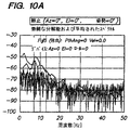
本発明による微動パターン検出、微動パターン分類、および微動パターン格納のためのスキームを実施するのに、いくつかの異なるアプローチがとられることが可能である。1つの例示的な実施形態を、図9〜12に関連して以下に説明する。微動パターンを分類するための全体的な方法が、図9の流れ図に示されている。図9では、ステップ900において、データセットが、複数のユーザから収集される。データセット収集は、ユーザが、所定の期間(例えば、5〜15秒)にわたって意図的な動きを導入せずに、デバイスを把持するよう求められる訓練/初期プロセスの一環であること、またはハンドヘルドデバイスの使用中に「オンザフライ」で実行されることが可能である。さらに、データ収集は、ハンドヘルドデバイスを所定の方向で把持している間に実行されることが可能である。図10(a)〜図10(d)に示される、いくつかの単に例示的な周波数スペクトルデータが、4つの異なる向きで自由空間ポインティングデバイス400を把持する特定のユーザに関して収集された。
Several different approaches can be taken to implement a scheme for fine movement pattern detection, fine movement pattern classification, and fine movement pattern storage according to the present invention. One exemplary embodiment is described below in connection with FIGS. The overall method for classifying the fine movement patterns is shown in the flowchart of FIG. In FIG. 9, in
図9に戻ると、収集されたデータは、次に、ハンドヘルドデバイス400の異なるユーザにそれぞれが関連付けられたクラスを識別するために処理されることが可能である。例えば、ステップ902で、1つまたは複数の特徴セットが、収集されたデータの各セットから、分類プロセスにおいて使用するために抽出されることが可能である。ステップ902で使用するために選択された特定の1つまたは複数の特徴セットが、微動データに関する良好なクラス区別をもたらすように選択され、例えば、分類プールの中で区別されるべきユーザの数、ステップ900で収集されるべき訓練データの量およびタイプ、デバイス特性、例えば、図8に関連して前述した状態情報、および関連するベイズユーザ情報(例えば、時間帯)を含む、微動プロセスを介してユーザ識別に関連付けられる実施パラメータに依存して、異なることが可能である。ステップ902で使用されることが可能な特徴セットの例示的なリストを、以下にテーブル1として提供する。
Returning to FIG. 9, the collected data can then be processed to identify classes each associated with a different user of the
以上の特徴セット、および対応する試験のいくつかに関する情報は、参照により開示が本明細書に組み込まれている、J.Jakubowski、K.Kwiatos、A.Chwaleba、S.Osowskiによる論文、「Higher Order Statistics and Neural Network For Tremor Recognition」、IEEE Transactions on Biomedical Engineering、vol.49、no.2、152〜159頁、IEEE、2002年2月で見ることができる。以下により詳細に説明する、本発明の1つの単に例示的な実施形態によれば、収集されたデータのパワースペクトル密度(PSD)からの低周波数スペクトルが、ステップ902において、特徴セットとして使用された。前段でリストアップしたドメイン、変換、その他に加え、特徴セットは、微動検出/識別が使用されるべきハンドヘルドデバイス内で利用可能なセンサの数およびタイプに基づいて異なることも可能である。例えば、前述の例示的な諸実施形態で説明したハンドヘルドの、自由空間ポインティングデバイス400では、微動データは、回転センサ、加速度計のいずれか、または両方、あるいは回転センサと加速度計の任意の組み合わせから収集されることが可能である。
Information on the above feature sets and some of the corresponding tests can be found in a paper by J. Jakubowski, K. Kwiatos, A. Chwaleba, S. Osowski, “Higher Order, whose disclosure is incorporated herein by reference. Statistics and Neural Network For Tremor Recognition ", IEEE Transactions on Biomedical Engineering, vol.49, no.2, pages 152-159, IEEE, February 2002. According to one exemplary embodiment of the present invention, described in more detail below, a low frequency spectrum from the power spectral density (PSD) of the collected data was used as a feature set in
収集されたデータから特徴セットを抽出した後、ステップ904で、特徴セットは、縮小されることが可能である。より具体的には、ステップ904で、特徴セットは、クラス(ユーザら)を区別する目的の特徴セットを最もよく表す特徴セットにまで縮小されることが可能である。例えば、ユーザ微動データのDC値が、縮小された特徴セットから除外されることが可能である一方で、ユーザ微動データの9Hz値は、縮小された特徴セットの中に含められることが可能である。というのは、この9Hz値は、異なるユーザの手の微動を区別する際に、より役に立つと見込まれるからである。縮小された特徴セットは、例えば、主成分分析(PCA)アルゴリズムを使用して判定されるMost Expressive Feature(MEF)セットであることが可能である。PCAアルゴリズムは、特徴セットの特異値分解を使用して、特徴ベクトルを最もよく表現する(例えば、最小平均二乗誤差(MMSE)の点で)基底ベクトルの適切なセットを自動的に求める。PCA技術を適用するための例は、参照により開示が本明細書に組み込まれている、P.NavarreteおよびJ.Ruiz-del Solar著、「Eigenspace-Based Recognition of Faces: Comparisons and a New Approach」、Image Analysis and Processing、2001年で見ることができる。
After extracting the feature set from the collected data, in
次に、縮小された特徴セットは、ステップ908で、クラスタを識別するのに使用されることが可能であり、この識別は、監督された学習、すなわち、いずれの個人ユーザが、いずれのデータセットに寄与したかについてのアプリオリの知識に基づいてプロセスが作用する学習を使用して、または監督されていない学習、すなわち、プロセスが、アプリオリの情報を全く有さない学習を使用して実行されることが可能である。例えば、K平均クラスタ化およびRBFニューラルネット分類を含め、様々な技術が、本発明の例示的な諸実施形態に従って、微動データに関連するクラスタを判定するのに適用されることが可能である。クラスタが識別されると、ステップ910で、現在のセンサ出力に基づき、新たな特徴ベクトルが、一部のクラスタの範囲内にあるか、または一部のクラスタの範囲外にあるかを区別するのに、すなわち、ハンドヘルドデバイス400を現在、把持しているユーザを識別するのに、識別されたクラスタに関連する推定された統計(例えば、平均および/または共分散)が、使用されることが可能である。学習方法は、初期ユーザ/クラスタインスタンス化の後、センサ動作中にクラスタ中心を純化することにより、センサ状態情報(例えば、図8に関連して前述した)の使用を介して強化されることが可能である。このようにして、最大量の利用可能なデータを使用してクラスタが純化されて(監督された形で)、さらなる監督されていない学習がサポートされる。
The reduced feature set can then be used in
検出された手の微動に基づいてユーザを識別するための前述した例示的な諸技術を試験するのに、他の4名のユーザに関連するデータセット(図10(a)〜図10(d)に示されたデータに加えて)が、おおむね図9の流れ図に関連して前述した形で、収集され、分析されて、手の微動の分析を使用して、異なるユーザらを区別する/識別することができることが証明された。データセットの2つは、ハンドヘルドデバイスを把持している同一の人から収集されたのに対して、他の3つのデータセットは、ハンドヘルドデバイスを把持している異なる人々から収集された。この試験では、データは、ステップ900で、5つのデータセットのそれぞれに関して、回転センサ812の両方から収集された。データセットのそれぞれが、ゼロ平均および単位分散を得るように処理された。この例示的な試験に関して、ステップ902で、PSD推定(例えば、ピーク周波数)からの低周波数スペクトルが、特徴セット抽出のために使用され、データ収集時間にわたって平均された。より具体的には、256ポイントFFTが、0〜30Hzの周波数範囲内のN=2048ポイントにわたって75%の重なりで平均された。抽出された特徴セットは、PCAアルゴリズムを使用して、38×20行列から20×20行列にまで縮小され、アルゴリズムは、抽出された特徴セットに関連する一部の固有ベクトルが、他の固有ベクトルほど表現力がなく、破棄されることが可能であると正しく認識した。図11は、この実施例では、ステップ904の一環として生成される固有値を示す。図11で、線1100は、特徴セット2(回転センサ504、z軸回転から収集されたデータ)に関連する固有値を示し、線1102は、特徴セット1(回転センサ502、y軸回転から収集されたデータ)に関連する固有値を示す。
To test the exemplary techniques described above for identifying users based on detected hand tremors, the datasets associated with the other four users (FIGS. 10 (a) -10 (d)). ) Is collected and analyzed, generally in the manner described above in connection with the flow diagram of FIG. 9, and uses hand tremor analysis to distinguish different users / Proven to be identified. Two of the data sets were collected from the same person holding the handheld device, while the other three data sets were collected from different people holding the handheld device. In this test, data was collected from both
この試験ケースでは、クラスタ化するステップは、いずれのユーザがいずれのデータセットを生成したかについてのアプリオリの知識(監督された学習)に基づいて実行された。実際のインプリメンテーションでは、自動化されたクラスタ化技術、例えば、前述した諸技術の1つが、ステップ906で使用される。この単に例示的な試験の場合、クラスタは、回転センサ502と回転センサ504から受け取られたデータに関して別々に識別されて、各データセットに関連する2つのクラス重心が定義された。次に、データセットの中の各ベクトルと2つのクラス重心との間の距離(この実施例では、ユークリッド距離)の合計が、計算された。このプロセスの結果が、図12に示されている。図12では、x軸は、縮小されたデータセットのベクトルを表し、y軸は、距離を表し、垂直の線は、距離を異なるクラス(ユーザ)中心に区分化する。各区分内で、関連するクラスのベクトル‐重心距離は、その他のクラスのベクトル‐重心距離よりも大幅に低く、良好なクラス分離、およびユーザがハンドヘルドデバイスに生じさせる手の微動に基づいてユーザを区別/識別する能力を示すことを見て取ることができる。例えば、特徴セットなどの一部の特定の選択が、例示される試験を実行するために行われたが、それらの選択は、本明細書で述べたとおり、単に例示的である。
In this test case, the clustering step was performed based on a priori knowledge (supervised learning) about which users generated which data sets. In an actual implementation, an automated clustering technique, such as one of the techniques described above, is used in step 906. In this merely exemplary test, the clusters were identified separately with respect to the data received from
本発明の例示的な諸実施形態によるいくつかの変形形態が、使用されることが可能である。例えば、クラスタが、ステップ908で識別されると、各クラスタの判別特徴を強調するために、クラス判別ステップが実行されることが可能である。クラス判別式は、セット内で最小グループ化をもたらし、セット間で最大距離をもたらす変換行列をデータに適用するように作用する。全体的な共分散を記述する行列、および複数のクラスタの各クラスタの共分散の合計を記述する別の行列を所与として、線形判別式のタスクは、クラス間の距離を最大化することと、クラス内散乱を最小化することを同時に行う線形変換を導き出すことである。パターン認識の一般的な分野において、いくつかの判別式、例えば、フィッシャ線形判別式(FLD)が知られているが、本明細書で説明されるとおり、手の微動に基づいてユーザを識別するという特定の問題にすべてが適している可能性は低い。前段の実施例で使用された1つの特定の判別式は、EFM-1判別式として知られており、参照により開示が本明細書に組み込まれている、C.LiuおよびH.Wechsler著、「Enhanced Fisher Linear Discriminant Models for Face Recognition」という題名の論文、Proc.14th International Conference on Pattern Recognition、Qeensland Australia、August、17〜20頁、1998年で説明されている。
Several variations according to exemplary embodiments of the present invention can be used. For example, once clusters are identified at
さらに、前述の試験は、本発明の前述した例示的な諸実施形態によるハンドヘルドポインティングデバイスを使用して実行されたが、ユーザの微動ベースの識別は、そのように限定されない。実際、微動ベースの識別は、微動データが生成されることが可能な任意のタイプのモーションセンサまたはモーションセンサ群(ジャイロスコープを含む)を有する、他の任意のタイプの自由空間ポインティングデバイスにおいて使用されることが可能である。さらに、本発明による微動ベースの識別は、ポインティングデバイスに限定さることもなく、1つまたは複数のモーションセンサを組み込んだ、またはハンドヘルドデバイスに関連する手の微動を測定するための他の何らかの機構を有する任意のハンドヘルドデバイス、例えば、セル電話機、PDAなどにおいて使用されることも可能である。訓練期間を使用して、例えば、ステップ900〜908が実行されることが可能であり、その後、ハンドヘルドデバイスは、現在のユーザの手の微動に関連するデータを単に収集し、そのデータを、あらかじめ確立されたユーザクラスと比較して、現在のユーザを識別することができる。次に、その識別情報が、実施例を前述した、いくつかの異なる応用例において使用されることが可能である。 Further, although the foregoing tests have been performed using a handheld pointing device according to the above-described exemplary embodiments of the present invention, user tremor-based identification is not so limited. In fact, tremor-based identification is used in any other type of free space pointing device that has any type of motion sensor or group of motion sensors (including gyroscopes) from which tremor data can be generated. Is possible. In addition, the tremor-based identification according to the present invention is not limited to a pointing device, but incorporates some other mechanism for measuring hand tremors incorporating one or more motion sensors or associated with a handheld device. It can also be used in any handheld device that has, for example, a cell phone, a PDA, etc. Using the training period, for example, steps 900-908 can be performed, after which the handheld device simply collects data related to the tremor of the current user's hand and stores that data in advance. The current user can be identified compared to the established user class. The identification information can then be used in a number of different applications as described above for the embodiments.
例えば、ユーザの身元(微動ベースの認識、または別の識別技術によって認識された)を使用して、そのユーザによって行われたジェスチャが解釈されて、ユーザインタフェースに、例えば、参照により前段で組み込まれた特許出願のユーザインタフェースにコマンドがシグナルされることが可能である。例えば、時間にわたる動きのパターンが、特定のインタフェースコマンドに関連付けられるジェスチャベースのコマンドシステムにおいて、異なるユーザらが、ハンドヘルドの時間にわたる、いくらか異なる動きパターンを使用して、同一のインタフェースコマンドを開始することができる(異なる筆跡スタイルを有する異なる人々と同様に)。ユーザ識別を可能にする能力は、次に、異なるジェスチャパターンにマップされ、例えば、ハンドヘルドの中、またはシステムの中に格納されて、システム全体が、時間にわたる動きの各パターンを、ユーザによって意図されるコマンドジェスチャとして正しく識別するようになることが可能である。 For example, using the user's identity (recognized by microtremor-based recognition, or another identification technique), gestures made by the user are interpreted and incorporated into the user interface, for example, by reference earlier. A command can be signaled to the user interface of a patent application. For example, in a gesture-based command system where a pattern of movement over time is associated with a specific interface command, different users initiate the same interface command using somewhat different movement patterns over the time of handheld (As well as different people with different handwriting styles). The ability to enable user identification is then mapped to different gesture patterns, for example stored in the handheld or in the system, and the entire system is intended by the user for each pattern of movement over time. It is possible to correctly identify as a command gesture.
(基準フレームマッピング)
前述したとおり、本発明の例示的な諸実施形態は、自由空間ポインティングデバイス内のセンサから受け取られた動きデータを処理して、そのデータを、自由空間ポインティングデバイスの筐体の基準フレームから、別の基準フレームに、例えば、ユーザの基準フレームに変換する。スクリーン上、例えば、テレビ上に表示されるユーザインタフェースを制御するのに使用される自由空間ポインティングデバイスの例示的な応用例では、ユーザの基準フレームは、テレビスクリーンに関連する座標系であることが可能である。いずれにせよ、筐体基準フレームから別の基準フレームへのデータの変換は、デバイスの見地からではなく、ユーザの見地からの操作をもたらすことにより、ハンドヘルドデバイスの使いやすさを向上させる。このため、ユーザが、自由空間ポインティングデバイスを把持しながら、ディスプレイの前方で左から右に手を動かすと、カーソルは、自由空間ポインティングデバイスの向きにかかわらず、左から右の方向に移動する。
(Reference frame mapping)
As described above, exemplary embodiments of the present invention process motion data received from sensors in a free space pointing device and separate the data from a reference frame of the free space pointing device housing. For example, the user's reference frame. In an exemplary application of a free space pointing device used to control a user interface displayed on a screen, eg, on a television, the user's reference frame may be a coordinate system associated with the television screen. Is possible. In any case, the conversion of data from the housing reference frame to another reference frame improves the usability of the handheld device by providing operations from the user's perspective rather than from the device's perspective. Therefore, when the user moves his / her hand from the left to the right in front of the display while holding the free space pointing device, the cursor moves from the left to the right regardless of the orientation of the free space pointing device.
この説明を簡単にするため、自由空間ポインティングデバイスに関連する例示的な処理システムが、例えば、より詳細に前述したとおり、図13に示されている。図13では、ハンドヘルドシステムは、1つまたは複数のセンサ1301、例えば、回転センサ、ジャイロスコープ、加速度計、磁力計、光センサ、カメラ、または以上の任意の組み合わせを使用して、動きを感知する。センサは、次に、ブロック1302で解釈されて、生じた動きの推定をもたらす。次に、処理ブロック1303が、デバイスの自然の(筐体)基準フレームからの測定された動きを、ユーザの基準フレームに変換する。次に、その動きが、意味のあるアクションにマップされ1304、アクションが、ブロック1305で解釈され、システムに転送されて、スクリーン上のカーソルを動かすことなどの、意味のある応答がもたらされる。
To simplify this description, an exemplary processing system associated with a free space pointing device is shown in FIG. 13, for example, as described in more detail above. In FIG. 13, the handheld system senses movement using one or
ブロック1303は、検出された動きを、デバイスの基準フレームではなく、ユーザの基準フレームに変換する。向きは、オイラー角、方向余弦行列(DCM)、または単位四元数を含む、多くの異なる数学的に類似した方法によって表現されることが可能である。位置は、一般に、メートル、センチメートル、フィート、インチ、およびマイルを含むが、以上には限定されない一貫した単位で、座標系原点からのオフセットとして表現される。前述した1つの例示的な実施形態では、自由空間ポインティングデバイスは、加速度および回転速度を含む慣性力を測定する。それらの力は、デバイス内に装着されたデバイスの筐体に相対的に測定される。測定されたデータをユーザ基準フレームに変換するため、デバイスは、デバイスの位置、およびデバイスの向きを推定する。 Block 1303 converts the detected motion into a user reference frame instead of a device reference frame. Orientation can be represented by many different mathematically similar methods, including Euler angles, direction cosine matrix (DCM), or unit quaternions. A position is generally expressed as an offset from the coordinate system origin in a consistent unit including, but not limited to, meters, centimeters, feet, inches, and miles. In one exemplary embodiment described above, the free space pointing device measures inertial forces including acceleration and rotational speed. Those forces are measured relative to the housing of the device mounted in the device. In order to convert the measured data into user reference frames, the device estimates the position of the device and the orientation of the device.
この例示的な実施形態では、ユーザ基準フレームは、静止しており、固定の向きを有するものと想定されるが、本発明によるこの技術は、時間につれ変化するフレームに直接に変換することによって、または静止したフレームにまず変換し、次に、動くフレームに変換することによって、ユーザの基準フレームが静止していないケースにも容易に拡張されることが可能であることが、当業者には理解されよう。静止した、固定の向きのユーザ基準フレーム例の場合、筐体フレームからユーザフレームへの変換は、以下の数式の使用によって実行されることが可能である。すなわち、
Pu=Rotate(Pb,Q)+Pdelta
Pu'=Rotate(Pb',Q)
Pu''=Rotate(Pb'',Q)
Wu=Rotate(Wb,Q)
Wu'=Rotate(Wb',Q)
ただし、
Rotateは、四元数回転演算子を表し、したがって、Rotate(A,Q)は、Q*AQに等しく、ただし、Q*は、共役四元数であり、ベクトルAは、Aに等しい複素成分と、0に等しい実成分とを有する四元数であり、
Puは、ユーザ基準フレームにおける位置であり、
Pbは、デバイス基準フレームにおける位置であり、
'は、微分を表す。したがって、Pu'は、ユーザ基準フレームにおける速度である、ユーザ基準フレームにおける位置の微分であり、
Wuは、ユーザ基準フレームにおける筐体角度でのデバイスの角速度であり、
Wbは、筐体基準フレームにおける筐体角度でのデバイスの角速度であり、
Pdeltaは、ユーザ基準フレーム座標系における、ユーザ基準フレームの原点と、筐体基準フレームとの差であり、
Qは、筐体フレームからユーザフレームへの回転を表す、正規化された回転四元数である。ユーザフレームから筐体フレームに回転させる回転四元数は、Q*であるので、QをR*で置き換えることができ、ただし、Rは、ユーザフレームから筐体フレームへの回転である。Qは、オイラー角および方向余弦行列(DCM)を含む、いくつかの等価の形態で表現されることが可能であり、前述の数式は、等価の形態においては、Qの異なる表現に基づき、わずかに異なる可能性があることに留意されたい。図14は、筐体基準フレームからユーザの基準フレームへの変換をグラフで示す。
In this exemplary embodiment, the user reference frame is assumed to be stationary and have a fixed orientation, but this technique according to the present invention directly translates into a time-varying frame by: Or, those skilled in the art will appreciate that by converting first to a stationary frame and then to a moving frame, the user's reference frame can be easily extended to the non-stationary case. Let's do it. In the case of a stationary, fixed orientation user reference frame example, the conversion from the housing frame to the user frame can be performed by use of the following equation: That is,
Pu = Rotate (Pb, Q) + Pdelta
Pu '= Rotate (Pb', Q)
Pu`` = Rotate (Pb '', Q)
Wu = Rotate (Wb, Q)
Wu '= Rotate (Wb', Q)
However,
Rotate represents a quaternion rotation operator, so Rotate (A, Q) is equal to Q * AQ, where Q * is a conjugate quaternion and vector A is a complex component equal to A And a quaternion having a real component equal to 0,
Pu is the position in the user reference frame,
Pb is the position in the device reference frame,
'Represents differentiation. Therefore, Pu ′ is the derivative of the position in the user reference frame, which is the velocity in the user reference frame,
Wu is the angular velocity of the device at the housing angle in the user reference frame,
Wb is the angular velocity of the device at the housing angle in the housing reference frame,
Pdelta is the difference between the origin of the user reference frame and the housing reference frame in the user reference frame coordinate system,
Q is a normalized rotation quaternion representing rotation from the housing frame to the user frame. Since the rotation quaternion rotated from the user frame to the housing frame is Q * , Q can be replaced by R * , where R is the rotation from the user frame to the housing frame. Q can be expressed in several equivalent forms, including Euler angles and direction cosine matrix (DCM), and in the equivalent form the above formula is based on a different expression of Q Please note that this can be different. FIG. 14 graphically illustrates the conversion from the housing reference frame to the user reference frame.
動作中、デバイスは、インプリメンテーションに依存する形でQを推定して、以上の変換を実行する。前述した1つの例示的なインプリメンテーションには、傾き(すなわち自由空間ポインティングデバイスがユーザによって把持される仕方に基づく自由空間ポインティングデバイスのx軸ロールの変動)を補償することがかかわる。向きは、筐体フレームの重力加速度に起因する加速度、Abをまず推定することにより、計算される。定義上、ユーザフレームにおける重力加速度に起因する加速度ベクトル、Agは、[0,0,-1]に設定される。重力加速度は、方位(z軸を中心とする回転)を推定することができないので、方位に関する筐体フレーム推定が使用される。したがって、回転四元数は、z=0平面に回転の軸を有する。以下は、回転四元数を計算するための、いくつかの数学的に等価な方法の1つである。すなわち、
V=‖Ab‖x‖Ag‖ (単位ベクトルのクロス乗積)
qV=‖V‖
α=sin-1|V|
Q=Quaternion[qV,α/2]=[qV*sin(α/2),cos(α/2)]
次に、位置が、ユーザフレームにおける加速度の二重積分として計算される。ユーザフレームにおける加速度は、前述のQによってユーザフレームに入るように回転させられた筐体フレームの加速度である。通常、原点は、デバイスが最初にアクティブにされた際、0であるものと想定されるが、原点は、通常の動作中に手動で、または自動的にリセットされてもよい。
In operation, the device estimates Q in an implementation dependent manner and performs the above transformations. One exemplary implementation described above involves compensating for tilt (ie, variations in the x-axis roll of the free space pointing device based on how the free space pointing device is gripped by the user). The orientation is calculated by first estimating the acceleration due to the gravitational acceleration of the housing frame, Ab. By definition, the acceleration vector due to gravity acceleration in the user frame, Ag, is set to [0,0, -1]. Gravity acceleration cannot estimate the azimuth (rotation around the z-axis), so case frame estimation for azimuth is used. Thus, the rotating quaternion has an axis of rotation in the z = 0 plane. The following is one of several mathematically equivalent methods for calculating a rotating quaternion. That is,
V = ‖Ab‖x‖Ag‖ (Cross product of unit vectors)
qV = ‖V‖
α = sin -1 | V |
Q = Quaternion [qV, α / 2] = [qV * sin (α / 2), cos (α / 2)]
The position is then calculated as the double integral of acceleration in the user frame. The acceleration in the user frame is the acceleration of the housing frame rotated to enter the user frame by Q described above. Normally, the origin is assumed to be 0 when the device is first activated, but the origin may be reset manually or automatically during normal operation.
一般に、デバイスが動いていない場合、Pu'、Pu''、Wu、およびWu''はすべて、0である。この例示的な実施形態では、Pb''およびWbが測定される。無限の数の回転Qが存在するが、利用可能なセットから最小限の回転が選択されて、Wbに基づき、Wuを推定するのに使用されることが可能である。代替的に、Qは、離散時間積分を使用して以下に示されるとおり、Wbを時間にわたって積分することにより、想定される開始オフセット向きQoを使用して計算されてもよい。すなわち、
WbAngle=|Wb|*period
QDELTA=[‖Wb‖sin(WbAngle),cos(WbAngle)]
QNEXT=Q0 **QDELTA
ただし、*は、乗算を表し、**は、四元数乗算を表す。さらなる安定性が、重力加速度および地球の磁場を含み、前述した結果と組み合わされた定常場ベクトルによってもたらされることが可能である。この組み合わせは、カルマンフィルタリングを含むが、それには限定されない、いくつかの数値方法およびフィルタリング方法を使用して達せられることが可能である。
In general, if the device is not moving, Pu ′, Pu ″, Wu, and Wu ″ are all zero. In this exemplary embodiment, Pb ″ and Wb are measured. There is an infinite number of rotations Q, but the minimum rotation from the available set can be selected and used to estimate Wu based on Wb. Alternatively, Q may be calculated using the assumed starting offset orientation Qo by integrating Wb over time, as shown below using discrete time integration. That is,
WbAngle = | Wb | * period
Q DELTA = [‖Wb‖sin (WbAngle), cos (WbAngle)]
Q NEXT = Q 0 ** Q DELTA
However, * represents multiplication and ** represents quaternion multiplication. Additional stability can be provided by stationary field vectors combined with the results described above, including gravitational acceleration and the Earth's magnetic field. This combination can be achieved using several numerical and filtering methods, including but not limited to Kalman filtering.
様々な異なるセンサが、それらのセンサが、デバイスの筐体に対する動きを測定する限り、使用されることが可能である。例示的なセンサには、加速度計、回転センサ、ジャイロスコープ、磁力計、およびカメラが含まれる。ユーザフレームは、静止している必要はない。例えば、ユーザの基準フレームが、ユーザの前腕であるように選択された場合、デバイスは、手首および指の動きだけに応答する。 A variety of different sensors can be used as long as they measure the movement of the device relative to the housing. Exemplary sensors include accelerometers, rotation sensors, gyroscopes, magnetometers, and cameras. The user frame need not be stationary. For example, if the user's reference frame is selected to be the user's forearm, the device responds only to wrist and finger movements.
可換特性は、本発明で説明される基準フレーム変換だけに当てはまることが、当業者には認識されよう。したがって、数学的操作の順序は、本明細書で説明される本発明に実質的に影響を与えることなく、変更されることが可能である。さらに、多くのモーション処理アルゴリズムは、特に、ユーザフレームが、不変の向きを有して静止しているように選択される場合、いずれの基準フレームでも同等に作用することが可能である。 Those skilled in the art will recognize that the commutative property applies only to the reference frame conversion described in the present invention. Thus, the order of mathematical operations can be changed without substantially affecting the invention described herein. Furthermore, many motion processing algorithms can work equally well with any reference frame, especially when the user frame is selected to be stationary with an unchanging orientation.
使用の容易さをもたらすことに加え、本発明のこの例示的な実施形態による基準フレーム変換は、ハンドヘルドデバイスインプリメンテーションにおける他の課題に対処するのにも使用されることが可能である。例えば、センサ(加速度計などの)が、筐体基準フレームにおける回転の中心に正確に配置されていない場合、測定される加速度には、フレームの加速度と、フレームの回転に起因する加速度成分がともに含まれる。したがって、測定された加速度は、以下の関係式を使用して、デバイスの筐体フレーム内の異なる目標位置に、まず変換されることが可能である。すなわち、
Abody=Aaccelerometer+ω'xR+ωx(ωxR)
ただし、Rは、加速度計から目標位置までのベクトルであり、ωは、筐体基準フレームの角速度であり、ω'は、筐体基準フレームの角加速度である。デバイスの筐体フレームが、加速度計からRにあるように構築されている場合、筐体フレームは、0の角加速度効果を有するべきであり、ユーザフレームにおけるデバイスの動きを計算するのに、より容易に使用されることが可能である。これにより、加速度計と、筐体基準フレームの中心との間の意図的な位置合わせ不良、または意図的でない位置合わせ不良が補償される。さらに、重力加速度ベクトルの推定は、回転の中心で作用する力の数がより少ないので、はるかに簡単になる。すると、
Auster=Rotate(Abody,Q)
であり、ただし、Qは、筐体基準フレームから加速度計基準フレームまでの回転である。
In addition to providing ease of use, the reference frame conversion according to this exemplary embodiment of the present invention can also be used to address other challenges in handheld device implementations. For example, if a sensor (such as an accelerometer) is not accurately placed at the center of rotation in the housing reference frame, the measured acceleration includes both the frame acceleration and the acceleration component due to the frame rotation. included. Thus, the measured acceleration can first be converted to a different target position within the device's housing frame using the following relation: That is,
Abody = Aaccelerometer + ω'xR + ωx (ωxR)
Where R is a vector from the accelerometer to the target position, ω is the angular velocity of the housing reference frame, and ω ′ is the angular acceleration of the housing reference frame. If the device's housing frame is constructed to be R from the accelerometer, the housing frame should have an angular acceleration effect of 0 and more to calculate the device's motion in the user frame It can be used easily. This compensates for an intentional misalignment between the accelerometer and the center of the housing reference frame, or an unintentional misalignment. Furthermore, the estimation of the gravitational acceleration vector is much simpler because there are fewer forces acting at the center of rotation. Then
Auster = Rotate (Abody, Q)
Where Q is the rotation from the housing reference frame to the accelerometer reference frame.
残念ながら、異なるユーザは、Rに関して異なる値を有する。例えば、あるユーザは、肘を回すことによってハンドヘルドデバイスを使用する可能性があるのに対して、別のユーザは、手首を回すことによってデバイスを使用する可能性がある。加えて、人々は、異なるサイズの手首および前腕を有する。より向上した使いやすさのため、ハンドヘルドのこの例示的な実施形態は、Rを動的に計算し、筐体原点を動かして、筐体原点が、角モーションに起因する最小の加速度成分を有するようにする。例示的な実施形態は、Rを[Rx,0,0]と定義し、Abody-Rotate[Ag,Q]を使用し、Abody-Rotate[Ag,Q]を最小化するRxについて解くことにより、Rを推定する。Rxを計算する最小化を実行することが可能な、再帰的最小二乗法およびカルマンフィルタリングを含む、多くの数値方法が存在することに留意されたい。 Unfortunately, different users have different values for R. For example, one user may use a handheld device by turning the elbow, while another user may use the device by turning the wrist. In addition, people have different sized wrists and forearms. For improved ease of use, this exemplary embodiment of the handheld dynamically calculates R and moves the housing origin so that the housing origin has the smallest acceleration component due to angular motion Like that. An exemplary embodiment defines R as [Rx, 0,0], uses Abody-Rotate [Ag, Q], and solves for Rx that minimizes Abody-Rotate [Ag, Q] Estimate R. Note that there are many numerical methods, including recursive least squares and Kalman filtering, that can perform minimization to calculate Rx.
以上に基づき、本発明は、1つの基準フレーム(例えば、筐体基準フレーム)から別の基準フレーム(例えば、ユーザの基準フレーム)にハンドヘルドデバイスの感知された動きをマップするための様々な技術を説明することが理解されよう。それらのマッピングは、ハンドヘルドデバイスの使用に関連する他のマッピング、例えば、感知された動きのカーソルの動きへのマッピングとは独立であることも、他のマッピングと組み合わせられることも可能である。さらに、本発明による変換は、動きの等式の入力側、または出力側の見地から、並進の動き、および回転の動き、またはそれらの動きの任意のサブセットのために、感知された動きを3つすべての次元で変換するように実行されることが可能である。さらに、感知された動きがマップされる、または変換される基準フレームの選択は、いくつかの異なる形で行われることが可能である。前段で提供された一実施例は、第2の基準フレームが、デバイスの傾きに関連するユーザの基準フレームであることを示すが、他の多くの変形形態が可能である。例えば、ユーザは、ユーザの所望の基準フレームを選択することができ、その設定が、複数のユーザ選好の1つとしてハンドヘルドの中に格納され、変換を実行するのに使用されることが可能である。他の実施例は、第2の基準フレームを選択するための技術として、ユーザ認識および明示的コマンド(例えば、ボタン選択またはユーザインタフェース選択)を含む。 Based on the foregoing, the present invention provides various techniques for mapping the sensed movement of a handheld device from one reference frame (e.g., a housing reference frame) to another reference frame (e.g., a user reference frame). It will be understood to explain. These mappings can be independent of other mappings associated with the use of the handheld device, eg, the mapping of sensed movement to cursor movement, or can be combined with other mappings. Furthermore, the transformation according to the present invention provides a sense of motion for translational and rotational motions or any subset of those motions from the input or output side of the motion equation. It can be performed to transform in all two dimensions. Furthermore, the selection of the reference frame to which the sensed motion is mapped or transformed can be done in several different ways. Although one example provided in the previous section shows that the second reference frame is the user's reference frame related to device tilt, many other variations are possible. For example, the user can select the user's desired reference frame and the setting can be stored in the handheld as one of multiple user preferences and used to perform the conversion. is there. Other embodiments include user recognition and explicit commands (eg, button selection or user interface selection) as techniques for selecting the second reference frame.
さらに、前述した例示的な諸実施形態の一部は、速度ドメインでデータを扱うが、本発明は、そのように限定されない。本発明によるマッピングまたは変換は、代替的に、またはさらに、例えば、位置データまたは加速度データに対して実行されることも可能であり、並進の動き、回転の動き、またはその両方の動きためであることも可能である。また、処理の順序は、重要ではない。例えば、ハンドヘルドデバイスが、ジェスチャコマンドを出力するのに使用されている場合、マッピングが、まず実行され、次に、ジェスチャが判定されることが可能であり、あるいはジェスチャが、まず判定されることが可能であり、次に、マッピングが実行されることが可能である。 Further, although some of the exemplary embodiments described above deal with data in the velocity domain, the present invention is not so limited. The mapping or transformation according to the invention can alternatively or additionally be performed, for example, on position data or acceleration data, for translational movements, rotational movements or both movements It is also possible. Also, the order of processing is not important. For example, if a handheld device is used to output a gesture command, the mapping can be performed first, then the gesture can be determined, or the gesture can be determined first. Is possible and then a mapping can be performed.
(意図的でない動きの除去)
本発明の例示的な諸実施形態によれば、感知された動きを処理するための諸技術は、例えば、ボタン作動などの、他のユーザ‐デバイス対話、および/または微動に起因する望ましくない効果を除去する。一般に、図15に示されるとおり、システムへの入力は、ハンドヘルドの自由空間ポインティングデバイスの人間の動きである。その動きが、デバイスによって感知され(ブロック1510)、例えば、ブロック1512で、代表的な動きになるように処理される。この処理の詳細な実施例は、前段で説明した。しかし、本発明のそれらの例示的な実施形態は、前述した例示的なハンドヘルドの自由空間ポインティングデバイス400における応用に限定されず、他のハンドヘルドデバイス、例えば、他のタイプの動きセンサを使用する自由空間ポインティングデバイスも含むことを明確に意図していることに留意されたい。代表的な動きは、次に、意味のある表現に変換され(ブロック1514)、この表現は、ブロック1516で、本発明の例示的な諸実施形態による例示的な「人的要因」技術によって処理される。本明細書で説明される例示的な実施形態では、人的要因処理1516の出力は、次に、例えば、2Dポインタの動きにマップされる。処理された動きは、次に、ハンドヘルドデバイスによって出力され、その動きの例が、スクリーン上のポインタの動きを制御するのに使用されることが可能なデータである。
(Removal of unintentional movement)
In accordance with exemplary embodiments of the present invention, techniques for processing sensed motion may be undesirable effects due to other user-device interactions, such as button actuation, and / or micromotion. Remove. In general, as shown in FIG. 15, the input to the system is the human movement of a handheld free space pointing device. The motion is sensed by the device (block 1510) and processed, for example, at
本発明のこの例示的な実施形態は、ボタンクリックを含む、ユーザによって開始されたイベント中の動きを処理するための様々な異なる技術を含む。第1の例示的な実施形態によれば、ユーザアクション、例えば、ボタンクリックが行われた後、モーションセンサ、例えば、回転センサ、加速度計、磁力計、ジャイロスコープ、カメラ、または以上の任意の組み合わせによって生成された動き情報を処理するのに、距離閾値と時間閾値がともに使用される。距離だけでは、ボタンクリック中に安定しているとともに応答性のよいポインタをもたらすのに十分でない可能性がある。ハンドヘルドデバイスによってボタンの押し下げが検出されると、1516からの出力されたポインタの動きは、距離が距離閾値を超えるまで、または経過した時間の量が時間閾値を超えるまで、抑圧される。距離閾値と時間閾値のいずれか、または両方が、例えば、ボタン押し下げアクションとボタン解放アクションに関して異なる可能性がある。例示的なボタン処理は、オプションとして、コマンドをハンドヘルドに送ることによって無効にされてもよい。 This exemplary embodiment of the present invention includes a variety of different techniques for handling movements during user initiated events, including button clicks. According to a first exemplary embodiment, after a user action, eg, a button click, is made, a motion sensor, eg, a rotation sensor, accelerometer, magnetometer, gyroscope, camera, or any combination of the above Both the distance threshold and the time threshold are used to process the motion information generated by. The distance alone may not be enough to provide a stable and responsive pointer during button clicks. When a button press is detected by the handheld device, the output pointer movement from 1516 is suppressed until the distance exceeds the distance threshold or the amount of time that has elapsed exceeds the time threshold. Either or both of the distance threshold and the time threshold can be different for, for example, a button press action and a button release action. Exemplary button processing may optionally be disabled by sending a command to the handheld.
また、異なるボタンが、互いに異なる閾値を有することも可能である。ボタンクリック中にハンドヘルドが経験する動きの量は、ユーザ、ボタン作動の力、ボタン移動距離、および支持体(通常、ユーザの手)のハンドヘルド中心に対するボタンの位置を含むが、以上には限定されない、いくつかの要因に依存する。ボタン動き処理パラメータは、各ボタンのパフォーマンスを最適化するように個々に設定されてもよい。加えて、パラメータは、セッション履歴に基づき、またはユーザがシステムに知られている場合、ユーザに基づき、学習されることも可能である。 It is also possible for different buttons to have different thresholds. The amount of movement the handheld experiences during a button click includes, but is not limited to, the user, the force of button actuation, the distance traveled by the button, and the position of the button relative to the handheld center of the support (usually the user's hand). Depends on several factors. Button motion processing parameters may be set individually to optimize the performance of each button. In addition, the parameters can be learned based on the session history or based on the user if the user is known to the system.
さらに、人的要因処理ファンクション1516が、ハンドヘルドデバイスの過去の動きの履歴を格納し、追跡することが可能である。例えば、ボタンが押し下げられたことをハンドヘルドデバイスが検出すると、ハンドヘルドデバイス内の処理ユニットが、ユーザによって開始されたボタンイベントより前の時点まで後退することができる。ボタンを物理的に作動させることは、心理学的試験および動的デバイス測定によって判定されることが可能な、不定の測定可能な時間を要する。ボタンが作動させられると、デバイスは、ボタン作動が行われる間/行われた後にモーションセンサから取り込まれたデータサンプルを削除することにより、ボタン作動が行われたのより前の状態に戻ることができる。したがって、ボタン押し下げ中に生じた不規則な動きが、無視され、「消去」される。例えば、検出されたボタン押し下げに応答して、ブロック1516からの出力が、検出された位置P1(ボタン押し下げアクションの後に続く)から、呼び戻された位置P2まで変化することが可能であり、この位置P2は、所定の期間、ボタン押し下げアクション検出に先立ってブロック1516によって、以前に出力されている。デバイスが、1つのボタンアクションを既に処理しており、別のボタンアクションが行われた際に、動きを依然として抑圧している場合、人的要因処理ファンクション1516が、後退プロセスを繰り返すことは必要ない可能性がある。
Further, the human
ユーザインタフェースにおいて、少なくとも2つの通常のタイプのボタンアクティブ化が行われる可能性がある。図16に示される第1のタイプ(微細モードクリック)では、ユーザは、小さい目標の上の正確な作動を意図し、デバイスを注意深く位置合わせし、動きを止め、次に、ボタンを押し下げる。第2のタイプ(粗モードクリック)では、目標は、大きく、ユーザは、次のアクションを予期し、すなわち、ユーザは、目標の上で止める、またはさまようことなしに、ポインタを単に減速させ、代わりに、「オンザフライ」で目標をクリックすることを目指すことができる。微細モードクリックの場合、前述した処理技術は、ハンドヘルドデバイス内のモーションセンサからの複合データ出力ストリームから、意図的でない動きデータを正確に除去するように動作する。しかし、第2のタイプの動きの場合、さらなる拡張が、パフォーマンスを向上させるのに役立つ可能性がある。 There may be at least two normal types of button activations in the user interface. In the first type shown in FIG. 16 (fine mode click), the user intends precise actuation over a small target, carefully aligns the device, stops movement, and then depresses the button. In the second type (coarse mode click), the goal is large and the user expects the next action, i.e. the user simply decelerates the pointer without stopping or wandering over the goal, instead In addition, you can aim to click on the target "on the fly". In the case of a fine mode click, the processing techniques described above operate to accurately remove unintentional motion data from the composite data output stream from the motion sensor in the handheld device. However, for the second type of movement, further expansion may help improve performance.
粗モードクリックによって提起されるさらなる課題に対処するため、人的要因処理ユニット1516は、第2の代替の技術、または補足的な技術を使用することができる。この第2の例示的な実施形態によれば、モーションセンサから受け取られた動きデータが、動きベクトルになるように処理され、ユーザは、ボタン作動中に、カーソルの何らかの動きの変化、またはデバイスからの他の関連する出力を意図する可能性があるものと想定される。ニュートンの第1法則で知られているとおり、「運動している物体は、運動を続ける」。このため、ハンドヘルドデバイス上でボタンが押されると、そのことにより、経路から外れる高周波数の動きが生じる。動きベクトル、およびフィルタリングされた動き情報を使用して、ポインティングデバイスからの出力は、ユーザによって開始されたイベント中、またはそのイベントの後、それまでの動きの履歴と整合性のある形で継続することが可能である。これは、処理チェーンにフィルタを追加することによって達せられることが可能である。フィルタは、イベント自体に関連する高周波数の動きを排除しながら、ユーザによって開始されたイベント中、およびそのイベント後の、意図された動きを許すように設計される。ローパスフィルタリングなどの多くの処理方法が、高周波数成分の除去を可能にするが、待ち時間の増加という犠牲を払う。待ち時間(デバイスの動きと、ポインタが動く時点の間の時間)は、ユーザに重要である可能性があるので、本発明の例示的な諸実施形態は、ユーザによって開始されたイベントが検出されると(例えば、ユーザイベントをユーザインタフェースに伝えるのにハンドヘルドデバイスによって使用されるのと同一の信号に基づき)、信号処理パスに入るように切り替えられる適応フィルタを使用することができる。適応フィルタは、急な高周波数のボタン押し下げを弱めるローパスフィルタとして構成される。適応フィルタリングブロックへのさらなる入力は、ボタンが完全に跳ね返り制御される前に行われる、オプションのボタン活動前警告である。ボタン活動前警告は、その警告なしの場合よりも早期に、ボタンイベントが処理に通知されることを可能にすることにより、フィルタ待ち時間用件を少なくする。ボタン活動前警告を伴う適応フィルタは、意図される動きと待ち時間の間の技術上のトレードオフを最小限に抑える。
To address the additional challenges posed by the coarse mode click, the human
本発明のさらに別の例示的な実施形態によれば、自由空間ポインティングデバイスの設計者は、通常、望ましくない動きの方向を設計時に知っているので、動きの乱れの方向は、したがって、デバイスのエルゴノミクス、および意図される使用に基づいて分かる。例えば、設計者は、デバイスを基準としたボタン作動の方向を知っている。主要な動きは、ボタン移動ベクトルに平行な直線の動き、またはユーザグリップを中心とするトルクによる回転の動きから成る。その知識は、ボタン作動の動きの知識を含む方向選好フィルタの実施を可能にする。例えば、フィルタ設計は、カルマンフィルタや適応フィルタなどの状態空間フィルタを含むことが可能である。そのようなフィルタは、ボタン作動中に、知られている方向の意図される経路からの所望されない逸脱を検出し、次に、ボタン作動中に、所望される動きの経路を補間する。この選好フィルタリングは、意図されないボタンの動きを依然として除去しながら、方向の意図される変化中、より応答性のよいポインタをもたらす。状態空間フィルタは、通常の使用の過程で、設計パラメータを学習するように拡張されることが可能であることが、当業者には認識されよう。 According to yet another exemplary embodiment of the present invention, the designer of a free space pointing device typically knows the direction of undesired motion at design time, so the direction of motion disturbance is therefore Based on ergonomics and intended use. For example, the designer knows the direction of button actuation relative to the device. The main movement consists of a linear movement parallel to the button movement vector, or a rotational movement with torque about the user grip. That knowledge enables the implementation of a directional preference filter that includes knowledge of button-operated movements. For example, the filter design can include a state space filter such as a Kalman filter or an adaptive filter. Such a filter detects undesired deviations from the intended path in a known direction during button activation and then interpolates the desired path of movement during button activation. This preference filtering results in a more responsive pointer during the intended change in direction while still removing unintended button movements. Those skilled in the art will recognize that state space filters can be extended to learn design parameters in the course of normal use.
本発明の例示的な諸実施形態による人的要因処理ファンクション916は、前述した技術のいずれか、または両方を実施することができ、両方が使用される場合、それらの技術の間で切り替えを行うクラシファイアを提供する。例えば、第1の正確なタイプのボタンクリックが検出された場合、第1の技術が使用されることが可能である。第2のそれほど正確でないボタンクリックが検出されると、第2の技術が使用されることが可能である。技術の間で切り替えを行うための1つのクラシファイアは、ボタン作動の時点における、またはボタン作動の直前の時点におけるハンドヘルドデバイスの速度を使用することができる。例えば、ハンドヘルドデバイスの速度が、所定の速度閾値を下回っている場合、ハンドヘルドデバイスが、所定の距離閾値を超えて動いたことをモーションセンサによって検出された動きが示すか、または所定の時間が経過するまで、検出されたイベントに続いて生成された動きデータを破棄する第1の技術が使用され、そうではなく、(b)ハンドヘルドデバイスの速度が、所定の速度を超えている場合、検出されたイベントに続いて生成された動きデータをフィルタリングする第2の技術が使用される。 The human factor processing function 916 according to exemplary embodiments of the present invention can implement either or both of the techniques described above, and switches between those techniques when both are used. Provide a classifier. For example, if a first accurate type of button click is detected, the first technique can be used. If a second less accurate button click is detected, the second technique can be used. One classifier for switching between technologies can use the speed of the handheld device at the time of button activation or just prior to button activation. For example, if the speed of the handheld device is below a predetermined speed threshold, the motion detected by the motion sensor indicates that the handheld device has moved beyond a predetermined distance threshold, or a predetermined time has elapsed Until the first technique is used to discard the motion data generated following the detected event, (b) if the speed of the handheld device exceeds the predetermined speed, it will be detected A second technique is used to filter the motion data generated following the event.
以上の例示的な諸実施形態で述べたボタンクリックまたはボタン押し下げは、ボタン押し下げとボタン解放をともに含むが、以上には限定されない。以上の技術のすべては、望ましくない動きを生じさせる、いずれの既知のデバイス対話にも適用されることが可能であり、ボタンクリックに限定されない。例えば、以上の諸技術は、スクロールホイール作動、タッチパッド使用、または容量性ストリップにも適用されることが可能である。このため、本発明の例示的な諸実施形態は、別のイベントをアクティブにすること、または非アクティブにすることに基づいて生じる不要な動きを取り消すための方法およびデバイスを説明する。 Button clicks or button presses described in the exemplary embodiments above include, but are not limited to, button presses and button releases. All of the above techniques can be applied to any known device interaction that produces undesirable movement, and is not limited to button clicks. For example, the above techniques can also be applied to scroll wheel actuation, touchpad usage, or capacitive strips. Thus, exemplary embodiments of the present invention describe methods and devices for canceling unwanted movement that occurs based on activating or deactivating another event.
前述した方法に関するパラメータは、イベントに関する予期される動き特性をサポートするように適合されることが可能である。例示的な実施形態では、ボタン押し下げに関するパラメータは、ボタン解放に関するパラメータとは異なることが可能である。動きの取り消しに加えて、ユーザインタフェースは、本発明によるユーザイベントの扱いに、さらなる制約を課す、または示唆することができる。例えば、Microsoft Windows(登録商標)オペレーティングシステムでは、ボタンが押し下げられている間にカーソルが動いた場合、「ドラッグ」アクションが開始される。したがって、ユーザによるボタン押し下げアクションに応答する動きデータ処理に関連するパラメータは、不要なドラッグイベントを防止するために、ボタン作動中のポインタの動きを制限する傾向がある値を有することが可能である。これとは対照的に、Microsoft Windows(登録商標)オペレーティングシステムにおけるボタン解放後のカーソルの動きは、ユーザインタフェースにおけるオブジェクトに対してほとんど影響を与えず、したがって、本発明による例示的な動きデータ処理は、ボタン押し下げに続く動きデータ処理に関連する、対応するパラメータと比べて、ポインタの動きをそれほど制限しない傾向にあるパラメータ(例えば、時間閾値および/または距離閾値、フィルタ係数、その他)を使用することが可能である。 The parameters for the methods described above can be adapted to support the expected motion characteristics for the event. In an exemplary embodiment, the parameter for button depression may be different from the parameter for button release. In addition to motion cancellation, the user interface may impose or impose further constraints on the handling of user events according to the present invention. For example, in the Microsoft Windows® operating system, if the cursor moves while the button is pressed, a “drag” action is initiated. Thus, parameters associated with motion data processing in response to a button press action by the user can have values that tend to limit pointer movement during button actuation to prevent unwanted drag events. . In contrast, cursor movement after button release in the Microsoft Windows® operating system has little effect on objects in the user interface, and therefore exemplary motion data processing according to the present invention is Use parameters that tend not to limit the movement of the pointer as much as the corresponding parameters associated with motion data processing following button presses (e.g., time and / or distance thresholds, filter coefficients, etc.) Is possible.
動きは、不要なボタンの動きを除去するのに役立つ、いくつかの異なる形で、速度ドメインまたは位置ドメインにおいて処理されることが可能である。速度ドメインにおける単純なフィルタリングが使用されてもよい。フィルタは、FIRフィルタまたはIIRフィルタであることが可能であるが、それらのフィルタは、望ましくない量の処理遅延を生じさせる可能性がある。適応フィルタが、それほど多くの遅延を生じさせずに、うまく使用されることが可能である。 The movement can be processed in the velocity or position domain in a number of different ways to help eliminate unwanted button movement. Simple filtering in the velocity domain may be used. The filters can be FIR filters or IIR filters, but they can cause an undesirable amount of processing delay. Adaptive filters can be used successfully without causing too much delay.
本発明の例示的な諸実施形態は、カルマンフィルタ(または拡張されたカルマンフィルタ)としても実施されることが可能である。カルマンフィルタは、最も可能性の高い使用シナリオ(静止している、または動いている)を選択し、適切な動きを適用することができる。ニューラルネットワークが、同一の結果のために使用されることが可能である。このため、本発明は、(a)イベントが生じたことを検出するため、(b)ユーザの意図する動きを推測するため、および(c)ハンドヘルドデバイスの実際の動きではなく、ユーザの意図する動きを解釈するための方法を提供することが理解されよう。動きは、6DOF自由空間ドメイン、またはマップされた2DOFポインティングドメインにおいてであることが可能である。6DOF自由空間ドメインは、デバイスの筐体基準フレーム、またはユーザの基準フレームにあることが可能である。 Exemplary embodiments of the present invention can also be implemented as Kalman filters (or extended Kalman filters). The Kalman filter can select the most likely usage scenario (stationary or moving) and apply the appropriate movement. A neural network can be used for the same result. For this reason, the present invention (a) detects that an event has occurred, (b) estimates the user's intended movement, and (c) the user's intention, not the actual movement of the handheld device. It will be appreciated that it provides a method for interpreting movement. The motion can be in the 6DOF free space domain or the mapped 2DOF pointing domain. The 6DOF free space domain can be in the device's housing reference frame or in the user's reference frame.
本発明の別の例示的な実施形態によれば、ユーザによって開始されたイベントに関連する動きは、モデル化されて、モーションセンサから収集された動きデータに基づいてハンドヘルドデバイスから出力をもたらす動きの等式に明示的に含められることが可能である。より具体的には、ユーザによって開始されたイベントのボタン押し下げの例を使用すると、ボタン押し下げによって生じさせられる動きが、アプリオリにモデル化されて、ボタン押し下げアクションに関連する1つまたは複数の例示的な動きの大きさおよび方向が算出され、それらの値が、次に、ハンドヘルドデバイスのメモリユニットの中に格納されることが可能である。次に、ボタン押し下げが検出されると、ハンドヘルドデバイスの処理ユニットは、動きの等式におけるモデル化された動きを使用して、出力が、ボタン押し下げに関連していた、モーションセンサによって検出された動きではなく、ユーザの意図する動きを反映するように、出力を適応させることができる。処理ユニットは、モデル化された値を様々な異なる形で使用すること、例えば、それらの値を、検出された動きの値から引くこと、特定のユーザによって開始されたイベントに関連するモデル化された値に基づいて、検出された動きの値を弱めること、ハンドヘルドの出力に関連する意味マップを調整することなどができる。 According to another exemplary embodiment of the present invention, motion associated with a user-initiated event is modeled to provide an output of motion from a handheld device based on motion data collected from a motion sensor. It can be explicitly included in the equation. More specifically, using the example of a button press on a user-initiated event, the movement caused by the button press is modeled a priori and one or more illustrative examples associated with the button press action. The magnitude and direction of the correct movement can be calculated and these values can then be stored in the memory unit of the handheld device. Next, when a button press is detected, the processing unit of the handheld device uses the modeled motion in the motion equation and the output is detected by a motion sensor that was related to the button press. The output can be adapted to reflect the movement intended by the user rather than the movement. The processing unit uses modeled values in a variety of different ways, e.g. subtracting them from detected motion values, modeled in relation to an event initiated by a particular user. Based on the measured value, the detected motion value can be weakened, the semantic map associated with the handheld output can be adjusted, and the like.
このため、本発明の例示的な諸実施形態は、テレビを制御することを含め、様々な用途のためにハンドヘルドリモコンを実施する革新的な方法を説明することを見て取ることができる。また、デバイスは、他のアプリケーションのために、例えば、パーソナルコンピュータに対する入力デバイスおよびオブジェクトコントロールとして使用されることも可能である。 Thus, exemplary embodiments of the present invention can be seen to describe innovative ways of implementing a handheld remote control for various applications, including controlling a television. The device can also be used for other applications, for example as an input device and object control for a personal computer.
リモコンはもはや、ボタンのミニチュアキーボードに似る必要がない(今日の通常のIRリモートは、40個のボタンを有する)。むしろ、本発明によるリモコンデバイスは、ポインティングの活動が、ボタンの単なる押し下げに加えて、情報を伝えるという点で、マウスによく似ていることが可能である。結果は、デバイスおよびアプリケーションのリモコンのための、はるかに強力なユーザ環境である。マウスのない今日のPCを想像すると、それが今日のTV制御環境である。次に、マウス様の機能をTVに追加することを想像されたい。もたらされるのは、大いに向上したユーザ体験である。要求されるのは、ポインティングおよびボタンアクティブ化を可能にすることができる無線ハンドヘルドだけである。本発明は、まさにそのようなデバイスを説明する。従来のリモコンに優るこの設計の1つの利点は、この設計が、ボタンアクティブ化を検出することに加え、ユーザが、スクリーン上でカーソルを位置づけることを可能にすることである。結果は、ジェスチャ認識に加え、スクリーンセンシティブなボタンおよびコントロールが可能なことである。結果は、機能を追加することが、新たなボタンが追加されることを要する、従来のリモコンと比べると、非常に強力で柔軟性があり、拡張性のあるユーザインタフェースである。本発明の例示的な諸実施形態は、例えば、デバイスの角速度を測定するMEMSベースの回転センサを使用するハンドヘルドリモコンデバイスを使用して、以上の能力を提供する。加えて、例示的な諸実施形態は、意図的でない動きを除去するティーチ筐体フレーム調整、較正、および後処理を可能にする。結果は、従来のハンドヘルドリモコンデバイスより、パフォーマンスが良好であり、安価であり、小さい完全に独特なインプリメンテーションである。 The remote no longer needs to resemble a button miniature keyboard (a typical IR remote today has 40 buttons). Rather, the remote control device according to the present invention can be very similar to a mouse in that the pointing activity conveys information in addition to simply pressing a button. The result is a much more powerful user environment for device and application remote controls. Imagine today's PC without a mouse, and that is today's TV control environment. Next, imagine adding mouse-like functionality to your TV. The result is a greatly improved user experience. All that is required is a wireless handheld that can allow pointing and button activation. The present invention describes just such a device. One advantage of this design over conventional remote controls is that in addition to detecting button activation, this design allows the user to position the cursor on the screen. The result is that in addition to gesture recognition, screen-sensitive buttons and controls are possible. The result is a very powerful, flexible, and extensible user interface compared to a traditional remote control where adding functionality requires adding new buttons. Exemplary embodiments of the present invention provide these capabilities using, for example, a handheld remote control device that uses a MEMS-based rotation sensor to measure the angular velocity of the device. In addition, the exemplary embodiments allow for teaching housing frame adjustment, calibration, and post-processing to remove unintentional movement. The result is a smaller, completely unique implementation that is better performing, cheaper and smaller than conventional handheld remote control devices.
それらの例示的な諸技術は、MEMSセンサを使用して、回転角速度および直線加速度を測定する。次に、較正が、静止検出と一緒に使用されて、生の読み取り値が調整され、スケーリングされる。次に、直線加速度読み取り値が、積分されて、ハンドヘルド筐体フレームの向きを算出するのに使用される。この向きデータが、次に、回転速度読み取り値を、適切な基準フレームにマップするのに使用される。最終ステップは、人間の微動のような意図的でない動きがフィルタリングされて除去されるように、すべての動きの読み取り値が、後処理されることである。 These exemplary techniques use a MEMS sensor to measure rotational angular velocity and linear acceleration. Calibration is then used in conjunction with stationary detection to adjust and scale the raw readings. The linear acceleration reading is then integrated and used to calculate the orientation of the handheld housing frame. This orientation data is then used to map the rotational speed reading to the appropriate reference frame. The final step is to post-process all motion readings so that unintentional motion, such as human tremors, is filtered out.
本発明の例示的な諸実施形態によるデータを処理するためのシステムおよび方法は、メモリデバイスの中に含まれる命令シーケンスを実行する1つまたは複数のプロセッサによって実行されることが可能である。そのような命令は、2次データ記憶デバイスなどの、他のコンピュータ可読媒体から、メモリデバイスの中に読み込まれてもよい。メモリデバイスの中に含まれる命令シーケンスの実行により、プロセッサは、例えば、前述したとおり、動作するようにさせられる。代替の諸実施形態では、本発明を実施するのに、ソフトウェア命令の代わりに、またはソフトウェア命令と組み合わせて、配線回路が使用されてもよい。 Systems and methods for processing data according to exemplary embodiments of the present invention can be performed by one or more processors executing instruction sequences contained within a memory device. Such instructions may be read into the memory device from other computer readable media such as a secondary data storage device. Execution of the instruction sequence contained within the memory device causes the processor to operate, for example, as described above. In alternative embodiments, wiring circuitry may be used in place of software instructions or in combination with software instructions to implement the invention.
前述した例示的な諸実施形態は、すべての点で、本発明を制限するのではなく、例示することを意図している。このため、本発明は、当業者によって本明細書に含まれる説明から導き出されることが可能な、詳細な実施の多くの変形が可能である。例えば、以上の例示的な諸実施形態は、とりわけ、デバイスの動きを検出する慣性センサの使用を説明したが、前述した信号処理に関連して、慣性センサの代わりに、または慣性センサに加えて、他のタイプのセンサ(例えば、超音波、磁気、または光学)が使用されることも可能である。すべてのそのような変形形態および変更形態が、添付の特許請求の範囲によって定義される、本発明の範囲および趣旨に含まれるものと考えられる。本出願の説明において使用されるいずれの要素、動作、または命令も、特に明記しない限り、本発明に不可欠である、または必須であると解釈されてはならない。また、本明細書で使用する冠詞「a」は、1つまたは複数のアイテムを含むことを意図している。 The exemplary embodiments described above are intended in all respects to illustrate rather than limit the invention. Thus, the present invention is capable of many variations in detailed implementation that can be derived from the description contained herein by a person skilled in the art. For example, while the above exemplary embodiments have described, among other things, the use of inertial sensors to detect device movement, in connection with the signal processing described above, instead of or in addition to inertial sensors. Other types of sensors (eg, ultrasound, magnetism, or optics) can also be used. All such variations and modifications are considered to be within the scope and spirit of the present invention as defined by the appended claims. Any element, operation, or instruction used in the description of this application should not be construed as essential or essential to the invention unless otherwise indicated. Also, as used herein, the article “a” is intended to include one or more items.
400 ポインティングデバイス
402、404 ボタン
406 スクロールホイール
408 ディスプレイ
410 カーソル
502、504、506 センサ
400 pointing device
402, 404 buttons
406 scroll wheel
408 display
410 cursor
502, 504, 506 sensors
Claims (36)
第2の軸を中心とするポインティングデバイスの回転を測定し、前記回転に関連する第2の回転出力を生成するための第2の回転センサと、
ポインティングデバイスの加速度を測定し、前記加速度に関連する加速度出力を出力するための加速度計と、
前記加速度計に基づいて前記第1の回転出力および前記第2の回転出力を変更するため、および前記変更された第1の回転出力、および前記変更された第2の回転出力に基づいて出力を生成するための処理ユニットとを含むポインティングデバイス。 A first rotation sensor for measuring the rotation of the pointing device about a first axis and generating a first rotation output related to the rotation;
A second rotation sensor for measuring the rotation of the pointing device about a second axis and generating a second rotation output associated with the rotation;
An accelerometer for measuring the acceleration of the pointing device and outputting an acceleration output related to the acceleration;
In order to change the first rotation output and the second rotation output based on the accelerometer, and output based on the changed first rotation output and the changed second rotation output A pointing device including a processing unit for generating.
ポインティングデバイスの動きを前記動きを示す出力に変換するため、および前記少なくとも1つのセンサの出力に基づき、ポインティングデバイスが静止しているかどうかを判定するための処理ユニットとを含むポインティングデバイス。 At least one sensor for detecting movement of the pointing device;
And a processing unit for converting the movement of the pointing device into an output indicative of the movement, and for determining whether the pointing device is stationary based on the output of the at least one sensor.
第1の軸を中心とするポインティングデバイスの回転を測定するため、および前記回転に関連する第1の回転出力を生成するための第1の回転センサと、
第2の軸を中心とするポインティングデバイスの回転を測定するため、および前記回転に関連する第2の回転出力を生成するための第2の回転センサと、
ポインティングデバイスの加速度を測定し、前記加速度に関連する加速度出力を出力するための加速度計とをさらに含む請求項13に記載のポインティングデバイス。 The at least one sensor is
A first rotation sensor for measuring the rotation of the pointing device about a first axis and for generating a first rotation output associated with the rotation;
A second rotation sensor for measuring the rotation of the pointing device about a second axis and for generating a second rotation output associated with the rotation;
14. The pointing device of claim 13, further comprising an accelerometer for measuring the acceleration of the pointing device and outputting an acceleration output associated with the acceleration.
前記検出するステップの結果、前記自由空間ポインティングデバイスを低電力状態にするステップとを含む前記自由空間ポインティングデバイスを制御するための方法。 Detecting a lack of movement associated with the free space pointing device;
Bringing the free space pointing device into a low power state as a result of the detecting step. The method for controlling the free space pointing device.
前記低電力状態を抜けるステップとをさらに含む請求項19に記載の制御する方法。 Detecting movement associated with the free space pointing device;
20. The method of controlling of claim 19, further comprising exiting the low power state.
前記動きが、前記デバイスが、ユーザによって現在、把持されていることを示すかどうかを判定するステップと、
前記判定するステップの結果に基づき、システムを制御するステップとを含む前記システムを制御するための方法。 Detecting movement associated with the device;
Determining whether the movement indicates that the device is currently being grasped by a user;
Controlling the system based on a result of the determining step.
前記身元に基づき、前記ユーザがメディアアイテムにアクセスすることを選択的に許すステップをさらに含む請求項25に記載の方法。 The system is a media system, and the step of restricting access is:
26. The method of claim 25, further comprising selectively allowing the user to access a media item based on the identity.
前記データをカーソルの動きにマップするための処理ユニットとを含むポインティングデバイス。 At least one sensor for outputting data relating to the angular velocity of the pointing device about at least one corresponding axis;
A pointing device including a processing unit for mapping the data to cursor movement.
前記角速度に関連するデータを出力するステップと、
前記データを処理して、関連するカーソルの動きの出力をもたらすステップとを含む自由空間ポインティングデバイスのための方法。 Sensing the angular velocity of a free space pointing device about at least one axis;
Outputting data relating to the angular velocity;
Processing the data to provide an output of the associated cursor movement.
Applications Claiming Priority (6)
| Application Number | Priority Date | Filing Date | Title |
|---|---|---|---|
| US56644404P | 2004-04-30 | 2004-04-30 | |
| US61257104P | 2004-09-23 | 2004-09-23 | |
| US64138305P | 2005-01-05 | 2005-01-05 | |
| US64141005P | 2005-01-05 | 2005-01-05 | |
| US64140505P | 2005-01-05 | 2005-01-05 | |
| PCT/US2005/015051 WO2005109879A2 (en) | 2004-04-30 | 2005-05-02 | Free space pointing devices and method |
Related Child Applications (1)
| Application Number | Title | Priority Date | Filing Date |
|---|---|---|---|
| JP2011133123A Division JP5363533B2 (en) | 2004-04-30 | 2011-06-15 | 3D handheld device and 3D control method |
Publications (2)
| Publication Number | Publication Date |
|---|---|
| JP2007535773A true JP2007535773A (en) | 2007-12-06 |
| JP2007535773A5 JP2007535773A5 (en) | 2008-07-03 |
Family
ID=35320943
Family Applications (2)
| Application Number | Title | Priority Date | Filing Date |
|---|---|---|---|
| JP2007511062A Withdrawn JP2007535773A (en) | 2004-04-30 | 2005-05-02 | Free space pointing device and pointing method |
| JP2011133123A Active JP5363533B2 (en) | 2004-04-30 | 2011-06-15 | 3D handheld device and 3D control method |
Family Applications After (1)
| Application Number | Title | Priority Date | Filing Date |
|---|---|---|---|
| JP2011133123A Active JP5363533B2 (en) | 2004-04-30 | 2011-06-15 | 3D handheld device and 3D control method |
Country Status (7)
| Country | Link |
|---|---|
| US (7) | US7239301B2 (en) |
| EP (1) | EP1759529A4 (en) |
| JP (2) | JP2007535773A (en) |
| KR (2) | KR100937572B1 (en) |
| CN (1) | CN102566751B (en) |
| TW (1) | TWI376520B (en) |
| WO (1) | WO2005109879A2 (en) |
Cited By (5)
| Publication number | Priority date | Publication date | Assignee | Title |
|---|---|---|---|---|
| JP2007241655A (en) * | 2006-03-08 | 2007-09-20 | Nintendo Co Ltd | Movement discrimination device and movement discrimination program |
| JP2009165826A (en) * | 2008-01-11 | 2009-07-30 | Sony Computer Entertainment America Inc | Gesture cataloguing and recognition |
| JP2010005332A (en) * | 2008-06-30 | 2010-01-14 | Nintendo Co Ltd | Posture calculating device, posture calculating program, game device and game program |
| WO2010056024A3 (en) * | 2008-11-14 | 2010-08-05 | Microinfinity, Inc. | Method and device for inputting force intensity and rotation intensity based on motion sensing |
| JP2012507068A (en) * | 2008-10-27 | 2012-03-22 | 株式会社ソニー・コンピュータエンタテインメント | Control device for communicating visual information |
Families Citing this family (326)
| Publication number | Priority date | Publication date | Assignee | Title |
|---|---|---|---|---|
| US7749089B1 (en) | 1999-02-26 | 2010-07-06 | Creative Kingdoms, Llc | Multi-media interactive play system |
| US7878905B2 (en) | 2000-02-22 | 2011-02-01 | Creative Kingdoms, Llc | Multi-layered interactive play experience |
| US6761637B2 (en) | 2000-02-22 | 2004-07-13 | Creative Kingdoms, Llc | Method of game play using RFID tracking device |
| US7445550B2 (en) | 2000-02-22 | 2008-11-04 | Creative Kingdoms, Llc | Magical wand and interactive play experience |
| US20010030667A1 (en) * | 2000-04-10 | 2001-10-18 | Kelts Brett R. | Interactive display interface for information objects |
| US7066781B2 (en) | 2000-10-20 | 2006-06-27 | Denise Chapman Weston | Children's toy with wireless tag/transponder |
| US20080060009A1 (en) * | 2000-12-22 | 2008-03-06 | Hillcrest Laboratories, Inc. | Client/server methods and systems for generating a user interface |
| US6967566B2 (en) | 2002-04-05 | 2005-11-22 | Creative Kingdoms, Llc | Live-action interactive adventure game |
| US20070066396A1 (en) | 2002-04-05 | 2007-03-22 | Denise Chapman Weston | Retail methods for providing an interactive product to a consumer |
| US8221321B2 (en) | 2002-06-07 | 2012-07-17 | Verathon Inc. | Systems and methods for quantification and classification of fluids in human cavities in ultrasound images |
| US8221322B2 (en) | 2002-06-07 | 2012-07-17 | Verathon Inc. | Systems and methods to improve clarity in ultrasound images |
| US20070276247A1 (en) * | 2002-06-07 | 2007-11-29 | Vikram Chalana | Systems and methods for ultrasound imaging using an inertial reference unit |
| US7819806B2 (en) | 2002-06-07 | 2010-10-26 | Verathon Inc. | System and method to identify and measure organ wall boundaries |
| GB2391625A (en) | 2002-08-09 | 2004-02-11 | Diagnostic Ultrasound Europ B | Instantaneous ultrasonic echo measurement of bladder urine volume with a limited number of ultrasound beams |
| US8797260B2 (en) * | 2002-07-27 | 2014-08-05 | Sony Computer Entertainment Inc. | Inertially trackable hand-held controller |
| US8313380B2 (en) | 2002-07-27 | 2012-11-20 | Sony Computer Entertainment America Llc | Scheme for translating movements of a hand-held controller into inputs for a system |
| US20060282873A1 (en) * | 2002-07-27 | 2006-12-14 | Sony Computer Entertainment Inc. | Hand-held controller having detectable elements for tracking purposes |
| US8570378B2 (en) | 2002-07-27 | 2013-10-29 | Sony Computer Entertainment Inc. | Method and apparatus for tracking three-dimensional movements of an object using a depth sensing camera |
| US7760248B2 (en) | 2002-07-27 | 2010-07-20 | Sony Computer Entertainment Inc. | Selective sound source listening in conjunction with computer interactive processing |
| US20060256081A1 (en) * | 2002-07-27 | 2006-11-16 | Sony Computer Entertainment America Inc. | Scheme for detecting and tracking user manipulation of a game controller body |
| US8686939B2 (en) | 2002-07-27 | 2014-04-01 | Sony Computer Entertainment Inc. | System, method, and apparatus for three-dimensional input control |
| US9393487B2 (en) | 2002-07-27 | 2016-07-19 | Sony Interactive Entertainment Inc. | Method for mapping movements of a hand-held controller to game commands |
| US7782297B2 (en) * | 2002-07-27 | 2010-08-24 | Sony Computer Entertainment America Inc. | Method and apparatus for use in determining an activity level of a user in relation to a system |
| US10086282B2 (en) * | 2002-07-27 | 2018-10-02 | Sony Interactive Entertainment Inc. | Tracking device for use in obtaining information for controlling game program execution |
| US9474968B2 (en) | 2002-07-27 | 2016-10-25 | Sony Interactive Entertainment America Llc | Method and system for applying gearing effects to visual tracking |
| US9682319B2 (en) | 2002-07-31 | 2017-06-20 | Sony Interactive Entertainment Inc. | Combiner method for altering game gearing |
| US7674184B2 (en) | 2002-08-01 | 2010-03-09 | Creative Kingdoms, Llc | Interactive water attraction and quest game |
| EP2070487B1 (en) | 2002-08-13 | 2014-03-05 | NeuroArm Surgical, Ltd. | Microsurgical robot system |
| US9177387B2 (en) | 2003-02-11 | 2015-11-03 | Sony Computer Entertainment Inc. | Method and apparatus for real time motion capture |
| US9446319B2 (en) | 2003-03-25 | 2016-09-20 | Mq Gaming, Llc | Interactive gaming toy |
| US20040268393A1 (en) | 2003-05-08 | 2004-12-30 | Hunleth Frank A. | Control framework with a zoomable graphical user interface for organizing, selecting and launching media items |
| US8072470B2 (en) | 2003-05-29 | 2011-12-06 | Sony Computer Entertainment Inc. | System and method for providing a real-time three-dimensional interactive environment |
| US8323106B2 (en) | 2008-05-30 | 2012-12-04 | Sony Computer Entertainment America Llc | Determination of controller three-dimensional location using image analysis and ultrasonic communication |
| US7874917B2 (en) | 2003-09-15 | 2011-01-25 | Sony Computer Entertainment Inc. | Methods and systems for enabling depth and direction detection when interfacing with a computer program |
| US10279254B2 (en) | 2005-10-26 | 2019-05-07 | Sony Interactive Entertainment Inc. | Controller having visually trackable object for interfacing with a gaming system |
| US7489299B2 (en) * | 2003-10-23 | 2009-02-10 | Hillcrest Laboratories, Inc. | User interface devices and methods employing accelerometers |
| EP1745458B1 (en) * | 2004-04-30 | 2017-01-11 | Hillcrest Laboratories, Inc. | Methods and devices for identifying users based on tremor |
| US7535456B2 (en) * | 2004-04-30 | 2009-05-19 | Hillcrest Laboratories, Inc. | Methods and devices for removing unintentional movement in 3D pointing devices |
| JP2007535773A (en) * | 2004-04-30 | 2007-12-06 | ヒルクレスト・ラボラトリーズ・インコーポレイテッド | Free space pointing device and pointing method |
| US7158118B2 (en) * | 2004-04-30 | 2007-01-02 | Hillcrest Laboratories, Inc. | 3D pointing devices with orientation compensation and improved usability |
| US8629836B2 (en) | 2004-04-30 | 2014-01-14 | Hillcrest Laboratories, Inc. | 3D pointing devices with orientation compensation and improved usability |
| US7746321B2 (en) | 2004-05-28 | 2010-06-29 | Erik Jan Banning | Easily deployable interactive direct-pointing system and presentation control system and calibration method therefor |
| US20060017690A1 (en) * | 2004-07-22 | 2006-01-26 | International Business Machines Corporation | Apparatus and method for motion detection in three dimensions |
| WO2006014810A2 (en) | 2004-07-29 | 2006-02-09 | Kevin Ferguson | A human movement measurement system |
| US7859523B2 (en) * | 2004-08-10 | 2010-12-28 | Microsoft Corporation | Direct navigation of two-dimensional control using a three-dimensional pointing device |
| KR100668311B1 (en) * | 2004-11-02 | 2007-01-12 | 삼성전자주식회사 | Apparatus and method for processing information using mobile communication terminal |
| US8137195B2 (en) | 2004-11-23 | 2012-03-20 | Hillcrest Laboratories, Inc. | Semantic gaming and application transformation |
| US8179366B2 (en) * | 2004-12-06 | 2012-05-15 | Naturalpoint, Inc. | Systems and methods for using a movable object to control a computer |
| JP2008527540A (en) * | 2005-01-05 | 2008-07-24 | ヒルクレスト・ラボラトリーズ・インコーポレイテッド | Distributed software configuration for user interface |
| JP2008527539A (en) * | 2005-01-05 | 2008-07-24 | ヒルクレスト・ラボラトリーズ・インコーポレイテッド | Scaling and layout method and system for processing one to many objects |
| CN101137996A (en) | 2005-01-07 | 2008-03-05 | 格斯图尔泰克股份有限公司 | Optical flow based tilt sensor |
| KR20080003788A (en) * | 2005-02-14 | 2008-01-08 | 힐크레스트 래보래토리스, 인크. | Methods and systems for enhancing television applications using 3d pointing |
| US7492367B2 (en) * | 2005-03-10 | 2009-02-17 | Motus Corporation | Apparatus, system and method for interpreting and reproducing physical motion |
| EP2902883A1 (en) * | 2005-05-04 | 2015-08-05 | Hillcrest Laboratories, Inc. | Method and system for scrolling in user interfaces |
| KR100537279B1 (en) * | 2005-05-12 | 2005-12-16 | 삼성전자주식회사 | Portable terminal with motion detecting function and method of motion detecting thereof |
| KR101403172B1 (en) * | 2005-05-17 | 2014-06-03 | 퀄컴 인코포레이티드 | Orientation-sensitive signal output |
| WO2006125133A2 (en) * | 2005-05-19 | 2006-11-23 | Hillcrest Laboratories, Inc. | Global navigation objects in user interfaces |
| US8555166B2 (en) | 2005-05-20 | 2013-10-08 | Hillcrest Laboratories, Inc. | Dynamic hyperlinking approach |
| US9285897B2 (en) | 2005-07-13 | 2016-03-15 | Ultimate Pointer, L.L.C. | Easily deployable interactive direct-pointing system and calibration method therefor |
| JP4244973B2 (en) * | 2005-08-03 | 2009-03-25 | ソニー株式会社 | Imaging system, camera control device, panoramic image display method and program |
| US20070067798A1 (en) * | 2005-08-17 | 2007-03-22 | Hillcrest Laboratories, Inc. | Hover-buttons for user interfaces |
| US7942745B2 (en) | 2005-08-22 | 2011-05-17 | Nintendo Co., Ltd. | Game operating device |
| US8313379B2 (en) | 2005-08-22 | 2012-11-20 | Nintendo Co., Ltd. | Video game system with wireless modular handheld controller |
| JP4805633B2 (en) | 2005-08-22 | 2011-11-02 | 任天堂株式会社 | Game operation device |
| US7927216B2 (en) | 2005-09-15 | 2011-04-19 | Nintendo Co., Ltd. | Video game system with wireless modular handheld controller |
| US8870655B2 (en) | 2005-08-24 | 2014-10-28 | Nintendo Co., Ltd. | Wireless game controllers |
| JP4262726B2 (en) | 2005-08-24 | 2009-05-13 | 任天堂株式会社 | Game controller and game system |
| US8308563B2 (en) | 2005-08-30 | 2012-11-13 | Nintendo Co., Ltd. | Game system and storage medium having game program stored thereon |
| US8157651B2 (en) | 2005-09-12 | 2012-04-17 | Nintendo Co., Ltd. | Information processing program |
| JP4622792B2 (en) * | 2005-10-07 | 2011-02-02 | ソニー株式会社 | Remote operation system, remote operation device, information processing device, remote operation method, information processing method, and computer program |
| US7606552B2 (en) * | 2005-11-10 | 2009-10-20 | Research In Motion Limited | System and method for activating an electronic device |
| US20070113207A1 (en) * | 2005-11-16 | 2007-05-17 | Hillcrest Laboratories, Inc. | Methods and systems for gesture classification in 3D pointing devices |
| TWI316195B (en) * | 2005-12-01 | 2009-10-21 | Ind Tech Res Inst | Input means for interactive devices |
| US8924889B2 (en) * | 2005-12-02 | 2014-12-30 | Hillcrest Laboratories, Inc. | Scene transitions in a zoomable user interface using a zoomable markup language |
| US8850478B2 (en) * | 2005-12-02 | 2014-09-30 | Hillcrest Laboratories, Inc. | Multimedia systems, methods and applications |
| CN101213505B (en) * | 2005-12-09 | 2012-05-23 | 汤姆森特许公司 | Handheld wireless graph input device and wireless remote controller |
| JP2007163251A (en) * | 2005-12-13 | 2007-06-28 | Fuji Xerox Co Ltd | Position measuring system |
| US9052161B2 (en) * | 2005-12-19 | 2015-06-09 | Raydon Corporation | Perspective tracking system |
| US7541566B2 (en) * | 2005-12-29 | 2009-06-02 | Nokia Corporation | Transmitter, receiver, and system with relative position detecting functionality between transmitters and receivers |
| US9411428B2 (en) * | 2006-01-31 | 2016-08-09 | Hillcrest Laboratories, Inc. | 3D pointing devices with keyboards |
| US8180672B2 (en) * | 2006-02-16 | 2012-05-15 | Hillcrest Laboratories, Inc. | Systems and methods for placing advertisements |
| KR100791294B1 (en) | 2006-03-02 | 2008-01-04 | 삼성전자주식회사 | Method for controlling the movement of graphical object and remote control using the same |
| JP4530419B2 (en) | 2006-03-09 | 2010-08-25 | 任天堂株式会社 | Coordinate calculation apparatus and coordinate calculation program |
| JP4151982B2 (en) | 2006-03-10 | 2008-09-17 | 任天堂株式会社 | Motion discrimination device and motion discrimination program |
| JP4684147B2 (en) | 2006-03-28 | 2011-05-18 | 任天堂株式会社 | Inclination calculation device, inclination calculation program, game device, and game program |
| US7796052B2 (en) * | 2006-03-29 | 2010-09-14 | Honeywell International Inc. | One button multifunction key fob for controlling a security system |
| US8210943B1 (en) | 2006-05-06 | 2012-07-03 | Sony Computer Entertainment America Llc | Target interface |
| KR100827236B1 (en) * | 2006-05-23 | 2008-05-07 | 삼성전자주식회사 | Pointing Device, Pointer movement method and Apparatus for displaying the pointer |
| US7986917B2 (en) * | 2006-07-10 | 2011-07-26 | Sony Ericsson Mobile Communications Ab | Method and system for data transfer from a hand held device |
| US9405372B2 (en) * | 2006-07-14 | 2016-08-02 | Ailive, Inc. | Self-contained inertial navigation system for interactive control using movable controllers |
| US8384665B1 (en) * | 2006-07-14 | 2013-02-26 | Ailive, Inc. | Method and system for making a selection in 3D virtual environment |
| US8795078B1 (en) * | 2006-07-14 | 2014-08-05 | Ailive Inc. | Method and system providing compatibility between two different controllers |
| JP4884867B2 (en) * | 2006-07-25 | 2012-02-29 | 任天堂株式会社 | Information processing apparatus and information processing program |
| US20080030466A1 (en) * | 2006-08-03 | 2008-02-07 | Leigh Simeon Keates | System and method for correcting positioning and triggering errors for aim-and-trigger devices |
| US20080222675A1 (en) * | 2006-08-29 | 2008-09-11 | Hillcrest Laboratories, Inc. | Pointing capability and associated user interface elements for television user interfaces |
| KR100855471B1 (en) * | 2006-09-19 | 2008-09-01 | 삼성전자주식회사 | Input device and method for providing movement information of the input device |
| USRE48417E1 (en) | 2006-09-28 | 2021-02-02 | Sony Interactive Entertainment Inc. | Object direction using video input combined with tilt angle information |
| US8781151B2 (en) | 2006-09-28 | 2014-07-15 | Sony Computer Entertainment Inc. | Object detection using video input combined with tilt angle information |
| US8310656B2 (en) | 2006-09-28 | 2012-11-13 | Sony Computer Entertainment America Llc | Mapping movements of a hand-held controller to the two-dimensional image plane of a display screen |
| CN101529364A (en) * | 2006-10-27 | 2009-09-09 | 诺基亚公司 | Method and apparatus for facilitating movement within a three dimensional graphical user interface |
| TWM316440U (en) * | 2006-11-07 | 2007-08-01 | Chang-Shi Wu | Input apparatus used with finger oriented method |
| US8771071B2 (en) * | 2006-11-22 | 2014-07-08 | Sony Computer Entertainment America Llc | System and method of rendering controller information |
| US9526995B2 (en) * | 2006-11-22 | 2016-12-27 | Sony Interactive Entertainment America Llc | Video game recording and playback with visual display of game controller manipulation |
| US20080148165A1 (en) * | 2006-11-22 | 2008-06-19 | Sony Computer Entertainment America Inc. | System and method of providing assistance over a network |
| US20080194333A1 (en) * | 2006-11-22 | 2008-08-14 | Gary Zalewski | System and method of providing assistance through incentives |
| US8508472B1 (en) | 2006-11-28 | 2013-08-13 | James W. Wieder | Wearable remote control with a single control button |
| US7796872B2 (en) | 2007-01-05 | 2010-09-14 | Invensense, Inc. | Method and apparatus for producing a sharp image from a handheld device containing a gyroscope |
| US8020441B2 (en) | 2008-02-05 | 2011-09-20 | Invensense, Inc. | Dual mode sensing for vibratory gyroscope |
| US8047075B2 (en) | 2007-06-21 | 2011-11-01 | Invensense, Inc. | Vertically integrated 3-axis MEMS accelerometer with electronics |
| US8952832B2 (en) | 2008-01-18 | 2015-02-10 | Invensense, Inc. | Interfacing application programs and motion sensors of a device |
| US20090265671A1 (en) * | 2008-04-21 | 2009-10-22 | Invensense | Mobile devices with motion gesture recognition |
| US7934423B2 (en) | 2007-12-10 | 2011-05-03 | Invensense, Inc. | Vertically integrated 3-axis MEMS angular accelerometer with integrated electronics |
| US8508039B1 (en) | 2008-05-08 | 2013-08-13 | Invensense, Inc. | Wafer scale chip scale packaging of vertically integrated MEMS sensors with electronics |
| US8250921B2 (en) | 2007-07-06 | 2012-08-28 | Invensense, Inc. | Integrated motion processing unit (MPU) with MEMS inertial sensing and embedded digital electronics |
| US8462109B2 (en) | 2007-01-05 | 2013-06-11 | Invensense, Inc. | Controlling and accessing content using motion processing on mobile devices |
| US8141424B2 (en) | 2008-09-12 | 2012-03-27 | Invensense, Inc. | Low inertia frame for detecting coriolis acceleration |
| JP5127242B2 (en) | 2007-01-19 | 2013-01-23 | 任天堂株式会社 | Acceleration data processing program and game program |
| KR100883900B1 (en) | 2007-04-30 | 2009-02-17 | 고려대학교 산학협력단 | Tangible user interface apparatus |
| US8133181B2 (en) | 2007-05-16 | 2012-03-13 | Verathon Inc. | Device, system and method to measure abdominal aortic aneurysm diameter |
| US8167803B2 (en) | 2007-05-16 | 2012-05-01 | Verathon Inc. | System and method for bladder detection using harmonic imaging |
| WO2008153976A1 (en) * | 2007-06-06 | 2008-12-18 | Hydro-Aire Inc. | Angular position sensor |
| JP4916390B2 (en) * | 2007-06-20 | 2012-04-11 | 任天堂株式会社 | Information processing program, information processing apparatus, information processing system, and information processing method |
| US8302033B2 (en) | 2007-06-22 | 2012-10-30 | Apple Inc. | Touch screen device, method, and graphical user interface for providing maps, directions, and location-based information |
| US7860676B2 (en) * | 2007-06-28 | 2010-12-28 | Hillcrest Laboratories, Inc. | Real-time dynamic tracking of bias |
| CN101578570B (en) * | 2007-07-04 | 2011-09-21 | 索尼株式会社 | Input device, control device, control system, control method and handheld device |
| US8363012B2 (en) * | 2007-07-31 | 2013-01-29 | Microsoft Corporation | Pointing device for interface with a graphical display |
| US7826999B1 (en) | 2007-08-20 | 2010-11-02 | Pni Corporation | Magnetic tilt compensated heading compass with adaptive zoffset |
| TW200909032A (en) * | 2007-08-20 | 2009-03-01 | Tai Sol Electronics Co Ltd | Three-dimensional wireless rocking lever |
| TWI334559B (en) * | 2007-08-28 | 2010-12-11 | Ind Tech Res Inst | Interactive pointing device |
| TWI391845B (en) * | 2007-09-14 | 2013-04-01 | Sony Corp | An input device, a control device, a control system, a control method, and a handheld device |
| KR101182286B1 (en) | 2007-09-19 | 2012-09-14 | 삼성전자주식회사 | Remote controller for sensing motion, image display apparatus controlling pointer by the remote controller, and methods thereof |
| KR101546845B1 (en) * | 2007-09-26 | 2015-08-24 | 톰슨 라이센싱 | Method and apparatus for providing roll compensation |
| US8359545B2 (en) | 2007-10-16 | 2013-01-22 | Hillcrest Laboratories, Inc. | Fast and smooth scrolling of user interfaces operating on thin clients |
| US8823645B2 (en) | 2010-12-28 | 2014-09-02 | Panasonic Corporation | Apparatus for remotely controlling another apparatus and having self-orientating capability |
| KR101451271B1 (en) | 2007-10-30 | 2014-10-16 | 삼성전자주식회사 | Broadcast receiving apparatus and control method thereof |
| TWI396117B (en) * | 2007-10-30 | 2013-05-11 | Imu Solutions Inc | Method for processing data from accelerometer to control cursor movement and cursor control device |
| USRE46076E1 (en) * | 2007-11-26 | 2016-07-19 | Sony Corporation | Input apparatus, control apparatus, control system, control method, and handheld apparatus |
| US8542907B2 (en) | 2007-12-17 | 2013-09-24 | Sony Computer Entertainment America Llc | Dynamic three-dimensional object mapping for user-defined control device |
| US8327272B2 (en) | 2008-01-06 | 2012-12-04 | Apple Inc. | Portable multifunction device, method, and graphical user interface for viewing and managing electronic calendars |
| KR100953861B1 (en) * | 2008-01-29 | 2010-04-20 | 한국과학기술원 | End point detection method, mouse device applying the end point detection method and operating method using the mouse device |
| US8565487B2 (en) * | 2008-02-06 | 2013-10-22 | Meditouch Ltd. | Method and system for measuring motion |
| KR101400230B1 (en) * | 2008-03-11 | 2014-05-28 | 삼성전자주식회사 | Three dimensional pointing input apparatus and method thereof |
| US8152642B2 (en) * | 2008-03-12 | 2012-04-10 | Echostar Technologies L.L.C. | Apparatus and methods for authenticating a user of an entertainment device using a mobile communication device |
| US9210355B2 (en) * | 2008-03-12 | 2015-12-08 | Echostar Technologies L.L.C. | Apparatus and methods for controlling an entertainment device using a mobile communication device |
| KR100940095B1 (en) * | 2008-03-17 | 2010-02-02 | (주)마이크로인피니티 | Apparatus for calculating pointer movement value and method for correcting pointer movement value and variation of angle, 3D pointing device using the same |
| TW201002402A (en) * | 2008-07-04 | 2010-01-16 | Asustek Comp Inc | Motion detecting input apparatus of the computer system |
| US20090259432A1 (en) * | 2008-04-15 | 2009-10-15 | Liberty Matthew G | Tracking determination based on intensity angular gradient of a wave |
| TW200945121A (en) * | 2008-04-23 | 2009-11-01 | Asustek Comp Inc | Input apparatus and operation method for computer |
| JP5163291B2 (en) * | 2008-06-02 | 2013-03-13 | ソニー株式会社 | INPUT DEVICE, CONTROL DEVICE, CONTROL SYSTEM, AND CONTROL METHOD |
| JP2010015535A (en) * | 2008-06-02 | 2010-01-21 | Sony Corp | Input device, control system, handheld device, and calibration method |
| KR100908099B1 (en) * | 2008-06-03 | 2009-07-16 | 엘지전자 주식회사 | Digital television, 3d pointing device and method of executing functions of digital television |
| US20140184509A1 (en) | 2013-01-02 | 2014-07-03 | Movea Sa | Hand held pointing device with roll compensation |
| TWI469000B (en) * | 2008-06-27 | 2015-01-11 | Hon Hai Prec Ind Co Ltd | Apparatus, method, and system for controlling electronic device and mouse |
| US8010313B2 (en) * | 2008-06-27 | 2011-08-30 | Movea Sa | Hand held pointing device with roll compensation |
| US20090322680A1 (en) * | 2008-06-30 | 2009-12-31 | Maurizio Sole Festa | Radio frequency pointing device |
| CN102099814B (en) * | 2008-07-01 | 2018-07-24 | Idhl控股公司 | 3D pointer mappings |
| KR101606834B1 (en) * | 2008-07-10 | 2016-03-29 | 삼성전자주식회사 | An input apparatus using motions and operations of a user, and an input method applied to such an input apparatus |
| US8342926B2 (en) | 2008-07-13 | 2013-01-01 | Sony Computer Entertainment America Llc | Game aim assist |
| KR20100009023A (en) * | 2008-07-17 | 2010-01-27 | (주)마이크로인피니티 | Apparatus and method for recognizing movement |
| US20100039381A1 (en) * | 2008-08-12 | 2010-02-18 | Apple Inc. | Rotatable input device |
| US20100053084A1 (en) * | 2008-08-27 | 2010-03-04 | Microsoft Corporation | Collapsible mouse with pinch-risk solution |
| WO2010027492A2 (en) * | 2008-09-04 | 2010-03-11 | Savant Systems Llc | Touch-sensitive wireless device and on screen display for remotely controlling a system |
| US8160311B1 (en) * | 2008-09-26 | 2012-04-17 | Philip Raymond Schaefer | System and method for detecting facial gestures for control of an electronic device |
| US8798956B2 (en) * | 2008-09-30 | 2014-08-05 | Apple Inc. | Method and apparatus for surface sensing input device |
| US8624836B1 (en) | 2008-10-24 | 2014-01-07 | Google Inc. | Gesture-based small device input |
| JP5464416B2 (en) * | 2008-10-31 | 2014-04-09 | ソニー株式会社 | Input device and method, and program |
| KR100920252B1 (en) * | 2008-11-07 | 2009-10-05 | 서창수 | The mouse controlled by movements of finger |
| US9058066B2 (en) * | 2008-11-12 | 2015-06-16 | Apple Inc. | Suppressing errant motion using integrated mouse and touch information |
| KR101577953B1 (en) | 2008-12-16 | 2015-12-17 | 삼성디스플레이 주식회사 | Touch sensible display device and method of determining touch |
| US8761434B2 (en) * | 2008-12-17 | 2014-06-24 | Sony Computer Entertainment Inc. | Tracking system calibration by reconciling inertial data with computed acceleration of a tracked object in the three-dimensional coordinate system |
| US8253801B2 (en) * | 2008-12-17 | 2012-08-28 | Sony Computer Entertainment Inc. | Correcting angle error in a tracking system |
| US8970707B2 (en) * | 2008-12-17 | 2015-03-03 | Sony Computer Entertainment Inc. | Compensating for blooming of a shape in an image |
| JP2010152761A (en) * | 2008-12-25 | 2010-07-08 | Sony Corp | Input apparatus, control apparatus, control system, electronic apparatus, and control method |
| US8441388B2 (en) * | 2009-01-06 | 2013-05-14 | Hong Kong Applied Science And Technology Research Institute Co., Ltd. | Remote control devices and methods |
| US8130134B2 (en) | 2009-01-06 | 2012-03-06 | Hong Kong Applied Science and Technology Research Institute Company Limited | Reduced instruction set television control system and method of use |
| US20100171696A1 (en) * | 2009-01-06 | 2010-07-08 | Chi Kong Wu | Motion actuation system and related motion database |
| US9459783B2 (en) | 2009-01-09 | 2016-10-04 | Hillcrest Laboratories, Inc. | Zooming and panning widget for internet browsers |
| KR101572847B1 (en) * | 2009-01-09 | 2015-11-30 | 삼성전자주식회사 | Method and apparatus for motion detecting in portable terminal |
| US20100188579A1 (en) * | 2009-01-29 | 2010-07-29 | At&T Intellectual Property I, L.P. | System and Method to Control and Present a Picture-In-Picture (PIP) Window Based on Movement Data |
| US20100192181A1 (en) * | 2009-01-29 | 2010-07-29 | At&T Intellectual Property I, L.P. | System and Method to Navigate an Electonic Program Guide (EPG) Display |
| US20100188429A1 (en) * | 2009-01-29 | 2010-07-29 | At&T Intellectual Property I, L.P. | System and Method to Navigate and Present Image Libraries and Images |
| WO2010095069A1 (en) * | 2009-02-17 | 2010-08-26 | Gerardus Geertruud De Vaal | Electronic control device |
| US8547326B2 (en) | 2009-02-24 | 2013-10-01 | Blackberry Limited | Handheld electronic device having gesture-based control and a method of using same |
| EP2224312B1 (en) | 2009-02-24 | 2014-01-01 | BlackBerry Limited | Handheld electronic device having gesture-based control and a method of using same |
| US8896527B2 (en) * | 2009-04-07 | 2014-11-25 | Samsung Electronics Co., Ltd. | Multi-resolution pointing system |
| US20100259610A1 (en) * | 2009-04-08 | 2010-10-14 | Celsia, Llc | Two-Dimensional Display Synced with Real World Object Movement |
| US9058063B2 (en) * | 2009-05-30 | 2015-06-16 | Sony Computer Entertainment Inc. | Tracking system calibration using object position and orientation |
| KR101607476B1 (en) | 2009-06-12 | 2016-03-31 | 삼성전자주식회사 | Apparatus and method for motion detection in portable terminal |
| US8970475B2 (en) * | 2009-06-19 | 2015-03-03 | Apple Inc. | Motion sensitive input control |
| CN102667672B (en) * | 2009-07-07 | 2014-04-02 | 闫文闻 | Acceleration motion identify method and system thereof |
| US8441438B2 (en) * | 2010-01-06 | 2013-05-14 | Cywee Group Limited | 3D pointing device and method for compensating movement thereof |
| US9760186B2 (en) | 2010-01-06 | 2017-09-12 | Cm Hk Limited | Electronic device for use in motion detection and method for obtaining resultant deviation thereof |
| JP5463790B2 (en) * | 2009-08-18 | 2014-04-09 | ソニー株式会社 | Operation input system, control device, handheld device, and operation input method |
| KR101589179B1 (en) | 2009-08-31 | 2016-02-12 | 엘지전자 주식회사 | Digital broadcast receiver controlled by screen remote controller and space remote controller and control method for the same |
| US20110050563A1 (en) * | 2009-08-31 | 2011-03-03 | Timothy Douglas Skutt | Method and system for a motion compensated input device |
| US8432305B2 (en) | 2009-09-03 | 2013-04-30 | Samsung Electronics Co., Ltd. | Electronic apparatus, control method thereof, remote control apparatus, and control method thereof |
| EP2299699A3 (en) * | 2009-09-04 | 2012-10-31 | Samsung Electronics Co., Ltd. | Image processing apparatus and controlling method of the same |
| CA2776877C (en) | 2009-10-06 | 2017-07-18 | Leonard Rudy Dueckman | A method and an apparatus for controlling a machine using motion based signals and inputs |
| US8601510B2 (en) * | 2009-10-21 | 2013-12-03 | Westinghouse Digital, Llc | User interface for interactive digital television |
| US8645093B2 (en) * | 2009-11-04 | 2014-02-04 | Qualcomm Incorporated | Calibrating multi-dimensional sensor for offset, sensitivity, and non-orthogonality |
| US8880373B2 (en) | 2009-11-04 | 2014-11-04 | Qualcomm Incorporated | Accurate magnetic compass in mobile electronic device |
| ES2338092A1 (en) * | 2009-11-16 | 2010-05-03 | Universidad Politecnica De Madrid | Device and method of biometric recognition based on a movement of the hand in the space with a device that integers an accelerometer (Machine-translation by Google Translate, not legally binding) |
| US8325136B2 (en) | 2009-12-01 | 2012-12-04 | Raytheon Company | Computer display pointer device for a display |
| JP2011128846A (en) * | 2009-12-17 | 2011-06-30 | Sony Corp | Operation input device and method, program, and electronic equipment |
| WO2011090467A1 (en) * | 2009-12-28 | 2011-07-28 | Hillcrest Laboratories Inc. | Tv internet browser |
| US8862576B2 (en) | 2010-01-06 | 2014-10-14 | Apple Inc. | Device, method, and graphical user interface for mapping directions between search results |
| US8552978B2 (en) | 2010-01-06 | 2013-10-08 | Cywee Group Limited | 3D pointing device and method for compensating rotations of the 3D pointing device thereof |
| TWI407102B (en) | 2010-01-26 | 2013-09-01 | Prolific Technology Inc | Method of sensing motion in a 3d space |
| US8913009B2 (en) | 2010-02-03 | 2014-12-16 | Nintendo Co., Ltd. | Spatially-correlated multi-display human-machine interface |
| AU2011204815B2 (en) * | 2010-02-03 | 2013-05-30 | Nintendo Co., Ltd. | Game system, controller device, and game process method |
| US20110199303A1 (en) * | 2010-02-18 | 2011-08-18 | Simpson Samuel K | Dual wrist user input system |
| US20110231484A1 (en) * | 2010-03-22 | 2011-09-22 | Hillcrest Laboratories, Inc. | TV Internet Browser |
| KR101066829B1 (en) * | 2010-04-16 | 2011-09-23 | 서창수 | Three-dimensional input device and it's input method |
| US9310887B2 (en) | 2010-05-06 | 2016-04-12 | James W. Wieder | Handheld and wearable remote-controllers |
| US8373658B2 (en) * | 2010-05-24 | 2013-02-12 | Cywee Group Limited | Motion sensing system |
| DE102010029668A1 (en) * | 2010-06-02 | 2011-12-08 | Robert Bosch Gmbh | Calibration of a three-axis magnetic field sensor |
| KR101199852B1 (en) * | 2010-06-21 | 2012-11-09 | 한국과학기술연구원 | Apparatus and method for Manipulating Image |
| US9307288B2 (en) | 2010-06-23 | 2016-04-05 | Hillcrest Laboratories, Inc. | Television sign on for personalization in a multi-user environment |
| US8547335B2 (en) * | 2010-07-30 | 2013-10-01 | International Business Machines Corporation | RFID-based input device |
| JP6243586B2 (en) | 2010-08-06 | 2017-12-06 | 任天堂株式会社 | GAME SYSTEM, GAME DEVICE, GAME PROGRAM, AND GAME PROCESSING METHOD |
| JP6184658B2 (en) | 2010-08-20 | 2017-08-23 | 任天堂株式会社 | GAME SYSTEM, GAME DEVICE, GAME PROGRAM, AND GAME PROCESSING METHOD |
| US10150033B2 (en) | 2010-08-20 | 2018-12-11 | Nintendo Co., Ltd. | Position calculation system, position calculation device, storage medium storing position calculation program, and position calculation method |
| JP5840386B2 (en) | 2010-08-30 | 2016-01-06 | 任天堂株式会社 | GAME SYSTEM, GAME DEVICE, GAME PROGRAM, AND GAME PROCESSING METHOD |
| JP5840385B2 (en) | 2010-08-30 | 2016-01-06 | 任天堂株式会社 | GAME SYSTEM, GAME DEVICE, GAME PROGRAM, AND GAME PROCESSING METHOD |
| US8988365B2 (en) * | 2010-09-01 | 2015-03-24 | Telefonaktiebolaget L M Ericsson (Publ) | Input precision method for minimizing erroneous entries stemming from instability of a mobile device using an accelerometer and apparatus to detect a shake and apparatus and computer program thereof |
| US20120062387A1 (en) * | 2010-09-10 | 2012-03-15 | Daniel Vik | Human interface device input filter based on motion |
| TWI481871B (en) * | 2010-09-28 | 2015-04-21 | J Mex Inc | Apparatus and system and method for interacting with target in operation area |
| KR101492310B1 (en) | 2010-11-01 | 2015-02-11 | 닌텐도가부시키가이샤 | Operating apparatus and information processing apparatus |
| CN102075625B (en) * | 2010-12-31 | 2013-01-09 | 惠州Tcl移动通信有限公司 | Dialing method, device, mobile phone and remote controller |
| US9030405B2 (en) | 2011-02-04 | 2015-05-12 | Invensense, Inc. | High fidelity remote controller device for digital living room |
| GB201102680D0 (en) * | 2011-02-16 | 2011-03-30 | Cosneta Ltd | Display apparatus and method thereof |
| US10146329B2 (en) * | 2011-02-25 | 2018-12-04 | Nokia Technologies Oy | Method and apparatus for providing different user interface effects for different motion gestures and motion properties |
| US9013264B2 (en) | 2011-03-12 | 2015-04-21 | Perceptive Devices, Llc | Multipurpose controller for electronic devices, facial expressions management and drowsiness detection |
| JP5689014B2 (en) | 2011-04-07 | 2015-03-25 | 任天堂株式会社 | Input system, information processing apparatus, information processing program, and three-dimensional position calculation method |
| US8884877B2 (en) * | 2011-04-29 | 2014-11-11 | Movea | Pointing device |
| US9541393B2 (en) | 2011-06-30 | 2017-01-10 | Qualcomm Incorporated | Reducing power consumption or error of digital compass |
| KR101893601B1 (en) | 2011-07-22 | 2018-08-31 | 삼성전자 주식회사 | Input apparatus of display apparatus, display system and control method thereof |
| KR101805922B1 (en) * | 2011-08-01 | 2017-12-07 | 엘지이노텍 주식회사 | method for correcting pointer movement value and pointing device using the same |
| EP2745120B1 (en) * | 2011-08-18 | 2015-10-14 | Koninklijke Philips N.V. | Estimating velocity in a horizontal or vertical direction from acceleration measurements |
| CA2847384C (en) * | 2011-09-30 | 2020-07-28 | Ims Solutions, Inc. | A method of correcting the orientation of a freely installed accelerometer in a vehicle |
| US9495018B2 (en) * | 2011-11-01 | 2016-11-15 | Qualcomm Incorporated | System and method for improving orientation data |
| US9462210B2 (en) | 2011-11-04 | 2016-10-04 | Remote TelePointer, LLC | Method and system for user interface for interactive devices using a mobile device |
| US9007302B1 (en) | 2011-11-11 | 2015-04-14 | Benjamin D. Bandt-Horn | Device and user interface for visualizing, navigating, and manipulating hierarchically structured information on host electronic devices |
| AT512592B1 (en) * | 2012-03-12 | 2017-07-15 | Isiqiri Interface Tech Gmbh | Computer system and a control method for it |
| US8875576B2 (en) * | 2012-03-21 | 2014-11-04 | The United States Of America As Represented By The Secretary Of The Navy | Apparatus and method for providing an in-plane inertial device with integrated clock |
| US20130247663A1 (en) * | 2012-03-26 | 2013-09-26 | Parin Patel | Multichannel Gyroscopic Sensor |
| JP2013210906A (en) * | 2012-03-30 | 2013-10-10 | Sony Corp | Control method, control device and program |
| KR101943435B1 (en) * | 2012-04-08 | 2019-04-17 | 삼성전자주식회사 | Flexible display apparatus and operating method thereof |
| US8698746B1 (en) * | 2012-04-24 | 2014-04-15 | Google Inc. | Automatic calibration curves for a pointing device |
| TW201346651A (en) * | 2012-05-01 | 2013-11-16 | Pixart Imaging Inc | Optical navigation device and trace smoothing method thereof |
| CN103389811B (en) * | 2012-05-11 | 2016-08-10 | 原相科技股份有限公司 | Optical navigator and smoothing track method thereof |
| US8638230B2 (en) | 2012-05-24 | 2014-01-28 | Google Inc. | Hardware attitude detection implementation of mobile devices with MEMS motion sensors |
| TWI552026B (en) * | 2012-06-07 | 2016-10-01 | 原相科技股份有限公司 | Hand-held pointing device |
| CN103488311B (en) * | 2012-06-12 | 2016-06-08 | 原相科技股份有限公司 | Hand-held finger is to device |
| CN103576843B (en) * | 2012-07-31 | 2016-07-06 | 腾讯科技(深圳)有限公司 | The control method of intelligent terminal and control device |
| CN103576901B (en) * | 2012-08-02 | 2017-10-03 | 腾讯科技(北京)有限公司 | Hand-hold electronic equipments enter the implementation method and the equipment of line cursor control to screen |
| US9113053B2 (en) * | 2012-08-10 | 2015-08-18 | Lg Electronics Inc. | Input apparatus and method for acquiring a scan image |
| US9329701B2 (en) | 2012-11-21 | 2016-05-03 | Google Technology Holdings LLC | Low power management of multiple sensor chip architecture |
| EP2738649A1 (en) * | 2012-11-29 | 2014-06-04 | Samsung Electronics Co., Ltd. | Input apparatus of display apparatus, display system and control method thereof |
| EP2753092A1 (en) * | 2013-01-02 | 2014-07-09 | Samsung Electronics Co., Ltd | Display apparatus, input apparatus, and method for compensating coordinates using the same |
| CN103152324B (en) * | 2013-01-29 | 2016-01-27 | 北京凯华信业科贸有限责任公司 | The user authen method of Behavior-based control feature |
| US9751757B2 (en) * | 2013-03-04 | 2017-09-05 | Kionix, Inc. | Single motor dynamic calibration unit |
| US10203815B2 (en) | 2013-03-14 | 2019-02-12 | Apple Inc. | Application-based touch sensitivity |
| US9482554B2 (en) * | 2013-05-02 | 2016-11-01 | Hillcrest Laboratories, Inc. | Gyroscope stabilizer filter |
| CN103297833B (en) * | 2013-05-10 | 2017-01-25 | 深圳Tcl新技术有限公司 | Data processing method and date processing device based on intelligent remote control system |
| EP3007042A4 (en) * | 2013-06-07 | 2017-06-28 | Seiko Epson Corporation | Electronic device and tap operation detection method |
| EP3019963A4 (en) | 2013-07-12 | 2017-02-08 | University of Iowa Research Foundation | Augmentative and alternative communication |
| DE102013214021A1 (en) * | 2013-07-17 | 2015-01-22 | Stabilo International Gmbh | power savings |
| EP3054693B1 (en) * | 2013-10-02 | 2019-12-25 | Samsung Electronics Co., Ltd | Image display apparatus and pointing method for same |
| US9143602B2 (en) * | 2013-11-26 | 2015-09-22 | Avaya Inc. | Methods and systems to ensure that the user of a touch or keypad operated device within a moving vehicle must use two hands for device operation |
| US9465455B2 (en) * | 2013-12-26 | 2016-10-11 | Dell Products L.P. | Active pen system |
| KR101403457B1 (en) * | 2013-12-27 | 2014-06-27 | (주)페타리 | Condition detectng device and method in a low power |
| TWI515432B (en) | 2014-01-15 | 2016-01-01 | 神達電腦股份有限公司 | Method and device for estimating periodic motion of a moving object |
| CN104796596B (en) * | 2014-01-20 | 2018-07-06 | 联想(北京)有限公司 | A kind of information processing method and electronic equipment |
| US9377626B2 (en) | 2014-02-18 | 2016-06-28 | Merge Labs, Inc. | Remote control augmented motion data capture |
| USD751072S1 (en) | 2014-02-18 | 2016-03-08 | Merge Labs, Inc. | Mobile head mounted display |
| WO2015153890A1 (en) | 2014-04-02 | 2015-10-08 | Hillcrest Laboratories, Inc. | Systems and methods for touch screens associated with a display |
| US9459027B2 (en) | 2014-04-22 | 2016-10-04 | King Fahd University Of Petroleum And Minerals | Intermittent absorption refrigeration system |
| AU2015249797B2 (en) * | 2014-04-23 | 2020-01-23 | Johnson & Johnson Surgical Vision, Inc. | Medical device data filtering for real time display |
| GB201408258D0 (en) | 2014-05-09 | 2014-06-25 | British Sky Broadcasting Ltd | Television display and remote control |
| CN103995658B (en) * | 2014-05-12 | 2018-06-01 | 联想(北京)有限公司 | A kind of information processing method, electronic equipment and control device of wireless |
| CN103955297B (en) * | 2014-05-20 | 2017-05-31 | 哈尔滨理工大学 | A kind of spatial operation formula mouse |
| US9342153B2 (en) | 2014-10-14 | 2016-05-17 | Sony Corporation | Terminal device and method for controlling operations |
| PL3218886T3 (en) | 2014-11-14 | 2019-12-31 | Spin Holding B.V. | Electronic control device |
| CN105808182B (en) | 2015-01-15 | 2019-09-17 | 财团法人工业技术研究院 | Display control method and system, advertisement breach judging device and video and audio processing device |
| US10830606B2 (en) * | 2015-02-09 | 2020-11-10 | Invensense, Inc. | System and method for detecting non-meaningful motion |
| USD755789S1 (en) | 2015-02-20 | 2016-05-10 | Merge Labs, Inc. | Mobile head mounted display |
| USD760701S1 (en) | 2015-02-20 | 2016-07-05 | Merge Labs, Inc. | Mobile head mounted display controller |
| US20180133596A1 (en) * | 2015-04-15 | 2018-05-17 | Thomason Licensing | Configuring translation of three dimensional movement |
| WO2017004544A1 (en) * | 2015-07-01 | 2017-01-05 | Solitonreach, Inc. | Systems and methods for three dimensional control of mobile applications |
| JP6677098B2 (en) * | 2015-07-01 | 2020-04-08 | 株式会社リコー | Spherical video shooting system and program |
| US10845195B2 (en) | 2015-07-01 | 2020-11-24 | Solitonreach, Inc. | System and method for motion based alignment of body parts |
| TWI580988B (en) * | 2015-07-24 | 2017-05-01 | P-Square Inc | Location Information Establishment Method and Spatial Location Method |
| CN105260004B (en) * | 2015-09-22 | 2019-03-05 | Oppo广东移动通信有限公司 | The screen rotation method and system of Android system terminal |
| DE102015219572A1 (en) * | 2015-10-09 | 2017-04-13 | Sivantos Pte. Ltd. | Method for operating a hearing device and hearing device |
| US10678337B2 (en) * | 2016-01-04 | 2020-06-09 | The Texas A&M University System | Context aware movement recognition system |
| US10429935B2 (en) | 2016-02-08 | 2019-10-01 | Comcast Cable Communications, Llc | Tremor correction for gesture recognition |
| US10118696B1 (en) | 2016-03-31 | 2018-11-06 | Steven M. Hoffberg | Steerable rotating projectile |
| US10024712B2 (en) * | 2016-04-19 | 2018-07-17 | Harman International Industries, Incorporated | Acoustic presence detector |
| US10101824B2 (en) * | 2016-07-27 | 2018-10-16 | Verily Life Sciences Llc | Apparatus, system, and method to stabilize penmanship and reduce tremor |
| TWI607347B (en) * | 2016-08-31 | 2017-12-01 | 張玉琪 | Spatial Positioning System and method |
| DE102016220448A1 (en) * | 2016-10-19 | 2018-04-19 | Ford Global Technologies, Llc | Device for supporting a maneuvering process of a motor vehicle |
| US10843068B2 (en) | 2017-01-18 | 2020-11-24 | Xvisio Technology Corp. | 6DoF inside-out tracking game controller |
| US11042262B2 (en) * | 2017-02-01 | 2021-06-22 | Opentv, Inc. | Menu modification based on controller manipulation data |
| CN106994687B (en) * | 2017-03-30 | 2019-08-20 | 北京卫星环境工程研究所 | Industrial robot end six-dimension force sensor Installation posture scaling method |
| US10810371B2 (en) | 2017-04-06 | 2020-10-20 | AIBrain Corporation | Adaptive, interactive, and cognitive reasoner of an autonomous robotic system |
| US10929759B2 (en) | 2017-04-06 | 2021-02-23 | AIBrain Corporation | Intelligent robot software platform |
| US10963493B1 (en) | 2017-04-06 | 2021-03-30 | AIBrain Corporation | Interactive game with robot system |
| US10839017B2 (en) | 2017-04-06 | 2020-11-17 | AIBrain Corporation | Adaptive, interactive, and cognitive reasoner of an autonomous robotic system utilizing an advanced memory graph structure |
| US11151992B2 (en) * | 2017-04-06 | 2021-10-19 | AIBrain Corporation | Context aware interactive robot |
| US20200285325A1 (en) * | 2017-10-24 | 2020-09-10 | Hewlett-Packard Development Company, L.P. | Detecting tilt of an input device to identify a plane for cursor movement |
| US10571994B1 (en) * | 2017-10-30 | 2020-02-25 | Snap Inc. | Systems and methods for reduced IMU power consumption in a wearable device |
| CA3092466A1 (en) * | 2018-03-07 | 2019-09-12 | University Of Massachusetts Medical School Office Of Technology Management | System for facilitating speech-based communication for individuals unable to speak or write |
| US11712637B1 (en) | 2018-03-23 | 2023-08-01 | Steven M. Hoffberg | Steerable disk or ball |
| JP2022506725A (en) | 2018-11-06 | 2022-01-17 | コート ボッツ インコーポレイテッド | Ball Recovery System (BALL RETRIEVAL SYSTEM) and Methods |
| US11660509B2 (en) | 2018-11-06 | 2023-05-30 | Court Bots, Inc. | Ball retrieval system and method |
| US11826616B2 (en) | 2018-11-06 | 2023-11-28 | Court Bots, Inc. | Ball retrieval system and method |
| US10985951B2 (en) | 2019-03-15 | 2021-04-20 | The Research Foundation for the State University | Integrating Volterra series model and deep neural networks to equalize nonlinear power amplifiers |
| CN110336995B (en) * | 2019-04-17 | 2021-03-30 | 中国信息通信研究院 | Jitter track generation method, device and system for photographing anti-jitter performance evaluation |
| CN110290311B (en) * | 2019-04-17 | 2021-03-30 | 中国信息通信研究院 | Method, device and system for generating jitter track for evaluating anti-jitter performance of video |
| DE102020202995A1 (en) | 2020-03-10 | 2021-09-16 | BSH Hausgeräte GmbH | Rod-shaped, centrally thickened control element, control device and method |
| US20240122499A1 (en) * | 2020-12-16 | 2024-04-18 | New York University | Wearable inertial sensor system and methods |
| TWI765509B (en) | 2020-12-31 | 2022-05-21 | 群光電子股份有限公司 | Pointing device and control method thereof |
| US11941184B2 (en) * | 2021-05-18 | 2024-03-26 | Snap Inc. | Dynamic initialization of 3DOF AR tracking system |
| US11243618B1 (en) * | 2021-05-25 | 2022-02-08 | Arkade, Inc. | Computer input devices having translational and rotational degrees of freedom |
| CN116930955B (en) * | 2023-09-15 | 2023-12-22 | 名商科技有限公司 | High-speed navigation automatic driving system |
Citations (4)
| Publication number | Priority date | Publication date | Assignee | Title |
|---|---|---|---|---|
| JPH09282085A (en) * | 1996-04-15 | 1997-10-31 | Mitsumi Electric Co Ltd | Position information input device |
| JP2001100908A (en) * | 1999-09-28 | 2001-04-13 | Fujitsu Ltd | Pen tip trace generating method, pen type input device, and pen mounting unit |
| JP2003140823A (en) * | 2001-11-08 | 2003-05-16 | Sony Computer Entertainment Inc | Information input device and information processing program |
| JP2003280813A (en) * | 2002-03-25 | 2003-10-02 | Ejikun Giken:Kk | Pointing device, pointer controller, pointer control method and recording medium with the method recorded thereon |
Family Cites Families (393)
| Publication number | Priority date | Publication date | Assignee | Title |
|---|---|---|---|---|
| GB591019A (en) | 1945-04-13 | 1947-08-05 | Charles Stanley Hudson | Improvements in or relating to remote indicating compasses |
| US2878286A (en) | 1945-06-09 | 1959-03-17 | Du Pont | Process for preparing symmetrical hexachlorodiphenyl urea |
| US3474241A (en) | 1966-10-06 | 1969-10-21 | Jack Kuipers | Coordinate transformer |
| US3660648A (en) | 1969-10-15 | 1972-05-02 | Northrop Corp | Angular rate coordinate transformer |
| US3931747A (en) | 1974-02-06 | 1976-01-13 | Sperry Rand Corporation | Gyroscopic stable reference device |
| US4038876A (en) | 1976-03-04 | 1977-08-02 | Systron Donner Corporation | Acceleration error compensated attitude sensing and control apparatus and method |
| NL7905061A (en) | 1979-06-29 | 1980-12-31 | Hollandse Signaalapparaten Bv | METHOD AND APPARATUS FOR AUTOMATIC MEASUREMENT OF AIMING ERRORS AND IMPROVING GUIDE VALUES IN SHOOTING AND AIMING BALLISTIC WEAPONS AGAINST MOVING TARGETS. |
| DE3103467A1 (en) | 1981-02-02 | 1982-08-26 | Teldix Gmbh, 6900 Heidelberg | COURSE ROTORS |
| US4558313A (en) | 1981-12-31 | 1985-12-10 | International Business Machines Corporation | Indicator to data processing interface |
| GB8301653D0 (en) | 1983-01-21 | 1989-07-05 | Secr Defence | Improvements in or relating to gun laying |
| US4578674A (en) | 1983-04-20 | 1986-03-25 | International Business Machines Corporation | Method and apparatus for wireless cursor position control |
| US4617634A (en) | 1983-06-28 | 1986-10-14 | Mitsubishi Denki Kabushiki Kaisha | Artificial satellite attitude control system |
| GB2146776B (en) * | 1983-09-16 | 1986-07-30 | Ferranti Plc | Accelerometer systems |
| JPS60143330A (en) | 1983-12-29 | 1985-07-29 | Matsushita Electric Ind Co Ltd | Photographic device |
| US4718078A (en) | 1985-08-19 | 1988-01-05 | Siemens Aktiengesellschaft | System for controlling motion of a robot |
| US4787051A (en) | 1986-05-16 | 1988-11-22 | Tektronix, Inc. | Inertial mouse system |
| IL78889A (en) | 1986-05-23 | 1989-09-28 | Elbit Computers Ltd | Electronic magnetic compass system |
| US5369889A (en) | 1986-07-07 | 1994-12-06 | Honeywell Inc. | Single gyro northfinder |
| US4745402A (en) | 1987-02-19 | 1988-05-17 | Rca Licensing Corporation | Input device for a display system using phase-encoded signals |
| JP2713899B2 (en) | 1987-03-30 | 1998-02-16 | 株式会社日立製作所 | Robot equipment |
| US4839838A (en) | 1987-03-30 | 1989-06-13 | Labiche Mitchell | Spatial input apparatus |
| RU2125853C1 (en) | 1987-04-29 | 1999-02-10 | Др.Хельмут Хуберти | Device for checking of load on parts of body |
| US5045843B1 (en) | 1988-12-06 | 1996-07-16 | Selectech Ltd | Optical pointing device |
| US5005551A (en) | 1989-02-03 | 1991-04-09 | Mcnelley Jerald R | In-line fuel heater |
| US5060175A (en) | 1989-02-13 | 1991-10-22 | Hughes Aircraft Company | Measurement and control system for scanning sensors |
| JPH0359619A (en) | 1989-07-28 | 1991-03-14 | Nippon Telegr & Teleph Corp <Ntt> | Optical amplifier |
| US5327161A (en) | 1989-08-09 | 1994-07-05 | Microtouch Systems, Inc. | System and method for emulating a mouse input device with a touchpad input device |
| DE3930581A1 (en) | 1989-09-13 | 1991-03-21 | Asea Brown Boveri | Work station for process control personnel - has display fields with windows accessed by mouse selection |
| JPH03206552A (en) | 1989-10-17 | 1991-09-09 | Sharp Corp | Display processing system |
| US5440326A (en) | 1990-03-21 | 1995-08-08 | Gyration, Inc. | Gyroscopic pointer |
| US5138154A (en) | 1990-04-04 | 1992-08-11 | Gyration Inc. | Shaft angle encoder with rotating off-axis interference pattern |
| US5128671A (en) * | 1990-04-12 | 1992-07-07 | Ltv Aerospace And Defense Company | Control device having multiple degrees of freedom |
| US5396265A (en) * | 1990-09-17 | 1995-03-07 | Massachusetts Institute Of Technology | Three-dimensional tactile computer input device |
| US5181181A (en) * | 1990-09-27 | 1993-01-19 | Triton Technologies, Inc. | Computer apparatus input device for three-dimensional information |
| JPH04218824A (en) | 1990-12-19 | 1992-08-10 | Yaskawa Electric Corp | Multidimensional information input device |
| JPH04277728A (en) | 1991-03-06 | 1992-10-02 | Nikon Corp | Vibration-proof device for camera |
| US5341466A (en) | 1991-05-09 | 1994-08-23 | New York University | Fractal computer user centerface with zooming capability |
| US6069594A (en) * | 1991-07-29 | 2000-05-30 | Logitech, Inc. | Computer input device with multiple switches using single line |
| US5293879A (en) | 1991-09-23 | 1994-03-15 | Vitatron Medical, B.V. | System an method for detecting tremors such as those which result from parkinson's disease |
| EP0606388A4 (en) | 1991-10-04 | 1994-12-07 | Micromed Systems Inc | Hand held computer input apparatus and method. |
| US5459489A (en) | 1991-12-05 | 1995-10-17 | Tv Interactive Data Corporation | Hand held electronic remote control device |
| JPH05157572A (en) | 1991-12-10 | 1993-06-22 | Pioneer Electron Corp | Navigation system |
| JPH05172575A (en) | 1991-12-19 | 1993-07-09 | Pioneer Electron Corp | Navigation equipment |
| US6400996B1 (en) * | 1999-02-01 | 2002-06-04 | Steven M. Hoffberg | Adaptive pattern recognition based control system and method |
| JPH0644005A (en) | 1992-01-24 | 1994-02-18 | Seiko Instr Inc | Coordinate input device |
| US5280744A (en) | 1992-01-27 | 1994-01-25 | Alliedsignal Inc. | Method for aiming towed field artillery pieces |
| GB2263666B (en) * | 1992-02-03 | 1995-05-17 | Guy Watson Kennedy | Writing implement and holder assembly |
| US5412421A (en) | 1992-04-30 | 1995-05-02 | Westinghouse Electric Corporation | Motion compensated sensor |
| US5359348A (en) | 1992-05-21 | 1994-10-25 | Selectech, Ltd. | Pointing device having improved automatic gain control and information reporting |
| US5543591A (en) | 1992-06-08 | 1996-08-06 | Synaptics, Incorporated | Object position detector with edge motion feature and gesture recognition |
| US5701424A (en) | 1992-07-06 | 1997-12-23 | Microsoft Corporation | Palladian menus and methods relating thereto |
| US5481957A (en) | 1992-07-06 | 1996-01-09 | Alliedsignal Inc. | Aiming and pointing system for ground based weapons equipment |
| US5296871A (en) * | 1992-07-27 | 1994-03-22 | Paley W Bradford | Three-dimensional mouse with tactile feedback |
| US5453758A (en) * | 1992-07-31 | 1995-09-26 | Sony Corporation | Input apparatus |
| JP2790965B2 (en) | 1992-08-19 | 1998-08-27 | 富士通株式会社 | Optical pointing system |
| US7098891B1 (en) * | 1992-09-18 | 2006-08-29 | Pryor Timothy R | Method for providing human input to a computer |
| US5430435A (en) | 1992-11-13 | 1995-07-04 | Rhys Resources | Adjustable athletic training system |
| US5524196A (en) | 1992-12-18 | 1996-06-04 | International Business Machines Corporation | Method and system for manipulating data through a graphic user interface within a data processing system |
| US5706448A (en) | 1992-12-18 | 1998-01-06 | International Business Machines Corporation | Method and system for manipulating data through a graphic user interface within a data processing system |
| DE69418908T2 (en) | 1993-01-26 | 2000-01-20 | Sun Microsystems Inc | Method and device for viewing information in a computer database |
| NL9300171A (en) | 1993-01-28 | 1994-08-16 | Josephus Godefridus Wilhelmus | Computer mouse based on a system of acceleration sensors disposed therein |
| US5383363A (en) | 1993-02-10 | 1995-01-24 | Ford Motor Company | Inertial measurement unit providing linear and angular outputs using only fixed linear accelerometer sensors |
| KR950011834B1 (en) | 1993-03-06 | 1995-10-11 | 지성남 | Apparatus and method for detecting motion change of a ball |
| JPH07284166A (en) * | 1993-03-12 | 1995-10-27 | Mitsubishi Electric Corp | Remote controller |
| US5822713A (en) | 1993-04-05 | 1998-10-13 | Contraves Usa | Guided fire control system |
| JPH0728591A (en) | 1993-05-13 | 1995-01-31 | Toshiba Corp | Space manipulation mouse system and space operation pattern input method |
| US5598187A (en) * | 1993-05-13 | 1997-01-28 | Kabushiki Kaisha Toshiba | Spatial motion pattern input system and input method |
| JPH0744315A (en) * | 1993-05-21 | 1995-02-14 | Sony Corp | Input device |
| US5524195A (en) | 1993-05-24 | 1996-06-04 | Sun Microsystems, Inc. | Graphical user interface for interactive television with an animated agent |
| US5405152A (en) | 1993-06-08 | 1995-04-11 | The Walt Disney Company | Method and apparatus for an interactive video game with physical feedback |
| US5373857A (en) | 1993-06-18 | 1994-12-20 | Forte Technologies, Inc. | Head tracking apparatus |
| US5484355A (en) * | 1993-10-01 | 1996-01-16 | Smith & Nephew Roylan, Inc. | System for therapeutic exercise and evaluation |
| US5546309A (en) | 1993-10-20 | 1996-08-13 | The Charles Stark Draper Laboratory, Inc. | Apparatus and method for autonomous satellite attitude sensing |
| GB2316482B (en) | 1993-11-25 | 1998-07-01 | Alps Electric Co Ltd | Inclination detection apparatus and input apparatus |
| JP2901476B2 (en) | 1993-12-27 | 1999-06-07 | アルプス電気株式会社 | Position detecting device and position detecting method |
| TW256900B (en) | 1993-11-25 | 1995-09-11 | Alps Electric Co Ltd | |
| JP3059619B2 (en) | 1993-11-25 | 2000-07-04 | アルプス電気株式会社 | Tilt detecting device and input device using the same |
| JP3789143B2 (en) | 1993-12-10 | 2006-06-21 | 株式会社ニコン | Camera optical system drive device |
| US5574479A (en) | 1994-01-07 | 1996-11-12 | Selectech, Ltd. | Optical system for determining the roll orientation of a remote unit relative to a base unit |
| US5615132A (en) | 1994-01-21 | 1997-03-25 | Crossbow Technology, Inc. | Method and apparatus for determining position and orientation of a moveable object using accelerometers |
| JP3630712B2 (en) | 1994-02-03 | 2005-03-23 | キヤノン株式会社 | Gesture input method and apparatus |
| JP3406046B2 (en) | 1994-03-03 | 2003-05-12 | オリンパス光学工業株式会社 | Camera with shake correction |
| JPH07271546A (en) | 1994-03-31 | 1995-10-20 | Olympus Optical Co Ltd | Image display control method |
| US5573011A (en) | 1994-04-08 | 1996-11-12 | Felsing; Gary W. | System for quantifying neurological function |
| JP3262677B2 (en) | 1994-05-02 | 2002-03-04 | 株式会社ワコム | Information input device |
| JP3204844B2 (en) | 1994-05-26 | 2001-09-04 | アルプス電気株式会社 | Angle detecting device and input device using the same |
| JP3217926B2 (en) | 1994-10-13 | 2001-10-15 | アルプス電気株式会社 | Spatial coordinate detector |
| JP3416291B2 (en) | 1994-10-05 | 2003-06-16 | アルプス電気株式会社 | Spatial coordinate detector |
| GB2289756B (en) | 1994-05-26 | 1998-11-11 | Alps Electric Co Ltd | Space coordinates detecting device and input apparatus using same |
| JPH0895704A (en) | 1994-09-28 | 1996-04-12 | Alps Electric Co Ltd | Spatial coordinate detecting device |
| ATE224567T1 (en) | 1994-06-09 | 2002-10-15 | Corp For Nat Res Initiatives | NOTICE ARRANGEMENT INTERFACE |
| US5525764A (en) | 1994-06-09 | 1996-06-11 | Junkins; John L. | Laser scanning graphic input system |
| US5645077A (en) | 1994-06-16 | 1997-07-08 | Massachusetts Institute Of Technology | Inertial orientation tracker apparatus having automatic drift compensation for tracking human head and other similarly sized body |
| US5741182A (en) | 1994-06-17 | 1998-04-21 | Sports Sciences, Inc. | Sensing spatial movement |
| KR100336151B1 (en) | 1994-06-27 | 2002-09-05 | 세르게이 페오도시에비키 코노발로브 | Servo accelerometer |
| JP3423418B2 (en) | 1994-06-30 | 2003-07-07 | 松下電器産業株式会社 | Moving body turning angle calculation device |
| US5617515A (en) | 1994-07-11 | 1997-04-01 | Dynetics, Inc. | Method and apparatus for controlling and programming a robot or other moveable object |
| JPH0836459A (en) | 1994-07-22 | 1996-02-06 | Fujitsu Ltd | Pointing device |
| JP2937759B2 (en) | 1994-07-25 | 1999-08-23 | 綜合警備保障株式会社 | Elevator non-stop control system |
| US5619249A (en) | 1994-09-14 | 1997-04-08 | Time Warner Entertainment Company, L.P. | Telecasting service for providing video programs on demand with an interactive interface for facilitating viewer selection of video programs |
| JP3194841B2 (en) | 1994-10-24 | 2001-08-06 | アルプス電気株式会社 | Tilt detecting device and input device using the same |
| US5572221A (en) | 1994-10-26 | 1996-11-05 | Telefonaktiebolaget Lm Ericsson | Method and apparatus for detecting and predicting motion of mobile terminals |
| GB2319374B (en) | 1994-11-30 | 1998-07-01 | Alps Electric Co Ltd | Remote coordinate designating device |
| JP3273531B2 (en) | 1994-11-30 | 2002-04-08 | アルプス電気株式会社 | Remote coordinate pointing device |
| US5671342A (en) | 1994-11-30 | 1997-09-23 | Intel Corporation | Method and apparatus for displaying information relating to a story and a story indicator in a computer system |
| JP3809198B2 (en) | 1995-03-23 | 2006-08-16 | キヤノン株式会社 | Hierarchical data display method and browser system |
| DE69534027T2 (en) | 1994-12-16 | 2006-01-12 | Canon K.K. | Hierarchical data display method and information processing method to realize it |
| US5638092A (en) | 1994-12-20 | 1997-06-10 | Eng; Tommy K. | Cursor control system |
| US6727887B1 (en) | 1995-01-05 | 2004-04-27 | International Business Machines Corporation | Wireless pointing device for remote cursor control |
| US5757362A (en) | 1995-01-05 | 1998-05-26 | International Business Machines Corporation | Recursive digital filter using fixed point arithmetic |
| US5835077A (en) | 1995-01-13 | 1998-11-10 | Remec, Inc., | Computer control device |
| JP3228845B2 (en) | 1995-01-31 | 2001-11-12 | アルプス電気株式会社 | Tilt detector |
| JP3548268B2 (en) | 1995-03-27 | 2004-07-28 | オリンパス株式会社 | Camera shake prediction device |
| US5757360A (en) | 1995-05-03 | 1998-05-26 | Mitsubishi Electric Information Technology Center America, Inc. | Hand held computer control device |
| JP3517482B2 (en) | 1995-06-08 | 2004-04-12 | キヤノン株式会社 | Coordinate detection device and method |
| US5736923A (en) | 1995-07-11 | 1998-04-07 | Union Switch & Signal Inc. | Apparatus and method for sensing motionlessness in a vehicle |
| JPH0944311A (en) | 1995-08-01 | 1997-02-14 | Alpine Electron Inc | Pointer positioning method for pointing device |
| EP0789223B1 (en) | 1995-08-28 | 2002-12-04 | Data Tec Co., Ltd. | Movement detector |
| US5748189A (en) | 1995-09-19 | 1998-05-05 | Sony Corp | Method and apparatus for sharing input devices amongst plural independent graphic display devices |
| US6732369B1 (en) | 1995-10-02 | 2004-05-04 | Starsight Telecast, Inc. | Systems and methods for contextually linking television program information |
| US6049823A (en) | 1995-10-04 | 2000-04-11 | Hwang; Ivan Chung-Shung | Multi server, interactive, video-on-demand television system utilizing a direct-access-on-demand workgroup |
| TW355774B (en) | 1995-10-12 | 1999-04-11 | Konami Co Ltd | TV game device, its loading support method and control method |
| JP3176541B2 (en) | 1995-10-16 | 2001-06-18 | シャープ株式会社 | Information retrieval device and information retrieval method |
| JPH09123497A (en) | 1995-11-06 | 1997-05-13 | Riso Kagaku Corp | Image forming device and image forming method |
| GB2307133A (en) | 1995-11-13 | 1997-05-14 | Secr Defence | Video camera image stabilisation system |
| US6100874A (en) | 1995-11-17 | 2000-08-08 | Immersion Corporation | Force feedback mouse interface |
| US5724265A (en) | 1995-12-12 | 1998-03-03 | Hutchings; Lawrence J. | System and method for measuring movement of objects |
| US5892501A (en) | 1996-01-17 | 1999-04-06 | Lg Electronics Inc, | Three dimensional wireless pointing device |
| US5867146A (en) | 1996-01-17 | 1999-02-02 | Lg Electronics Inc. | Three dimensional wireless pointing device |
| US5703623A (en) | 1996-01-24 | 1997-12-30 | Hall; Malcolm G. | Smart orientation sensing circuit for remote control |
| US5698784A (en) | 1996-01-24 | 1997-12-16 | Gyration, Inc. | Vibratory rate gyroscope and methods of assembly and operation |
| US6463328B1 (en) | 1996-02-02 | 2002-10-08 | Michael Sasha John | Adaptive brain stimulation method and system |
| US6164808A (en) * | 1996-02-09 | 2000-12-26 | Murata Mfg. Co., Ltd. | Three-dimensional data input device |
| US5692956A (en) | 1996-02-09 | 1997-12-02 | Mattel, Inc. | Combination computer mouse and game play control |
| US5661502A (en) | 1996-02-16 | 1997-08-26 | Ast Research, Inc. | Self-adjusting digital filter for smoothing computer mouse movement |
| US5902968A (en) | 1996-02-20 | 1999-05-11 | Ricoh Company, Ltd. | Pen-shaped handwriting input apparatus using accelerometers and gyroscopes and an associated operational device for determining pen movement |
| JPH09230997A (en) | 1996-02-20 | 1997-09-05 | Ricoh Co Ltd | Pen type input device |
| JP4033929B2 (en) | 1996-05-27 | 2008-01-16 | 株式会社リコー | Pen-type input device |
| JPH09274534A (en) | 1996-04-04 | 1997-10-21 | Ricoh Co Ltd | Pen type input device |
| US5825350A (en) | 1996-03-13 | 1998-10-20 | Gyration, Inc. | Electronic pointing apparatus and method |
| JPH09251350A (en) | 1996-03-18 | 1997-09-22 | Matsushita Electric Ind Co Ltd | Menu selection device |
| US5796395A (en) | 1996-04-02 | 1998-08-18 | Wegener Internet Projects Bv | System for publishing and searching interests of individuals |
| US6072467A (en) | 1996-05-03 | 2000-06-06 | Mitsubishi Electric Information Technology Center America, Inc. (Ita) | Continuously variable control of animated on-screen characters |
| JPH09322089A (en) | 1996-05-27 | 1997-12-12 | Fujitsu Ltd | Broadcasting program transmitter, information transmitter, device provided with document preparation function and terminal equipment |
| JPH09325860A (en) | 1996-06-04 | 1997-12-16 | Alps Electric Co Ltd | Coordinate input device |
| KR100188659B1 (en) | 1996-06-28 | 1999-06-01 | 윤종용 | Broadcasting program guide display device |
| US5989157A (en) | 1996-08-06 | 1999-11-23 | Walton; Charles A. | Exercising system with electronic inertial game playing |
| AU3908297A (en) | 1996-08-06 | 1998-02-25 | Starsight Telecast Incorporated | Electronic program guide with interactive areas |
| US6057831A (en) | 1996-08-14 | 2000-05-02 | Samsung Electronics Co., Ltd. | TV graphical user interface having cursor position indicator |
| US6181333B1 (en) | 1996-08-14 | 2001-01-30 | Samsung Electronics Co., Ltd. | Television graphical user interface having channel and program sorting capabilities |
| US6191781B1 (en) | 1996-08-14 | 2001-02-20 | Samsung Electronics, Ltd. | Television graphical user interface that combines electronic program guide with graphical channel changer |
| US6411308B1 (en) | 1996-08-14 | 2002-06-25 | Samsung Electronics Co., Ltd. | Television graphical user interface having variable channel control bars |
| US6195089B1 (en) | 1996-08-14 | 2001-02-27 | Samsung Electronics Co., Ltd. | Television graphical user interface having variable channel changer icons |
| US5978043A (en) | 1996-08-14 | 1999-11-02 | Samsung Electronics Co., Ltd. | TV graphical user interface that provides customized lists of programming |
| US6016144A (en) | 1996-08-14 | 2000-01-18 | Samsung Electronics Co., Ltd. | Multi-layered television graphical user interface |
| US5835156A (en) | 1996-08-14 | 1998-11-10 | Samsung Electroncis, Ltd. | Television graphical user interface employing remote random access pointing device |
| US5955988A (en) | 1996-08-14 | 1999-09-21 | Samsung Electronics Co., Ltd. | Graphical user interface for establishing installation location for satellite based television system |
| US5940072A (en) | 1996-08-15 | 1999-08-17 | Samsung Information Systems America | Graphics decompression using system ROM indexing in TV set top box |
| US6115028A (en) * | 1996-08-22 | 2000-09-05 | Silicon Graphics, Inc. | Three dimensional input system using tilt |
| US5790121A (en) | 1996-09-06 | 1998-08-04 | Sklar; Peter | Clustering user interface |
| JP3823389B2 (en) | 1996-09-10 | 2006-09-20 | 株式会社ニコン | Blur detection device and photographing device |
| JP3314625B2 (en) | 1996-09-11 | 2002-08-12 | 松下電器産業株式会社 | Light amount filter and manufacturing method thereof |
| JPH1093936A (en) | 1996-09-18 | 1998-04-10 | Toshiba Corp | Broadcast transmitter, broadcast receiver and video reservation device |
| JP3263012B2 (en) | 1996-10-01 | 2002-03-04 | 株式会社ソニー・コンピュータエンタテインメント | Operation device for game machine |
| DE69624848T2 (en) | 1996-10-15 | 2003-10-09 | Swisscom Ag Bern | METHOD FOR CHECKING A SPEAKER |
| EP0837418A3 (en) | 1996-10-18 | 2006-03-29 | Kabushiki Kaisha Toshiba | Method and apparatus for generating information input using reflected light image of target object |
| US5889506A (en) | 1996-10-25 | 1999-03-30 | Matsushita Electric Industrial Co., Ltd. | Video user's environment |
| US5745226A (en) | 1996-11-04 | 1998-04-28 | Litton Systems, Inc. | Passive optical velocity measurement device and method |
| US5870079A (en) | 1996-11-12 | 1999-02-09 | Legaltech, Inc. | Computer input device and controller therefor |
| US5883619A (en) | 1996-11-12 | 1999-03-16 | Primax Electronics Ltd. | Computer mouse for scrolling a view of an image |
| US6037933A (en) | 1996-11-13 | 2000-03-14 | Samsung Electronics Co., Ltd. | TV graphical user interface for providing user access to preset time periods of TV program information |
| US6154723A (en) | 1996-12-06 | 2000-11-28 | The Board Of Trustees Of The University Of Illinois | Virtual reality 3D interface system for data creation, viewing and editing |
| US5786805A (en) | 1996-12-27 | 1998-07-28 | Barry; Edwin Franklin | Method and apparatus for improving object selection on a computer display by providing cursor control with a sticky property |
| CA2248364C (en) | 1997-01-08 | 2006-03-28 | Ferdinand Peer | Instrument for compensating for hand tremor during the manipulation of fine structures |
| US5796354A (en) * | 1997-02-07 | 1998-08-18 | Reality Quest Corp. | Hand-attachable controller with direction sensing |
| JPH10240434A (en) | 1997-02-27 | 1998-09-11 | Matsushita Electric Ind Co Ltd | Command menu selecting method |
| US6005565A (en) | 1997-03-25 | 1999-12-21 | Sony Corporation | Integrated search of electronic program guide, internet and other information resources |
| JP3678386B2 (en) | 1997-03-28 | 2005-08-03 | 株式会社リコー | Pen-type input device |
| GB2325537B8 (en) | 1997-03-31 | 2000-01-31 | Microsoft Corp | Query-based electronic program guide |
| US5982369A (en) | 1997-04-21 | 1999-11-09 | Sony Corporation | Method for displaying on a screen of a computer system images representing search results |
| US6005551A (en) | 1997-04-25 | 1999-12-21 | Microsoft Corporation | Offline force effect rendering |
| JP3776206B2 (en) | 1997-05-07 | 2006-05-17 | 株式会社リコー | Pen-type input device |
| US5881321A (en) | 1997-05-09 | 1999-03-09 | Cammotion, Inc.. | Camera motion sensing system |
| US6397387B1 (en) | 1997-06-02 | 2002-05-28 | Sony Corporation | Client and server system |
| SE512719C2 (en) | 1997-06-10 | 2000-05-02 | Lars Gustaf Liljeryd | A method and apparatus for reducing data flow based on harmonic bandwidth expansion |
| US6188392B1 (en) | 1997-06-30 | 2001-02-13 | Intel Corporation | Electronic pen device |
| KR100317632B1 (en) | 1997-07-21 | 2002-02-19 | 윤종용 | Menu selection control method |
| US6175362B1 (en) | 1997-07-21 | 2001-01-16 | Samsung Electronics Co., Ltd. | TV graphical user interface providing selection among various lists of TV channels |
| JP3710603B2 (en) | 1997-07-25 | 2005-10-26 | 株式会社リコー | Pen-type input device |
| US6680694B1 (en) | 1997-08-19 | 2004-01-20 | Siemens Vdo Automotive Corporation | Vehicle information system |
| US7175528B1 (en) * | 1997-08-22 | 2007-02-13 | Biometric Recognition, Llc | Passive biometric customer identification and tracking system |
| JP3748483B2 (en) | 1997-09-12 | 2006-02-22 | 株式会社リコー | Posture input device, pen-type input device having posture input function, and pen-type input system having the pen-type input device |
| US6043807A (en) | 1997-09-23 | 2000-03-28 | At&T Corp. | Mouse for positioning a cursor on a computer display and having a removable pen-type input device |
| US6005578A (en) | 1997-09-25 | 1999-12-21 | Mindsphere, Inc. | Method and apparatus for visual navigation of information objects |
| US5953683A (en) | 1997-10-09 | 1999-09-14 | Ascension Technology Corporation | Sourceless orientation sensor |
| US5912612A (en) | 1997-10-14 | 1999-06-15 | Devolpi; Dean R. | Multi-speed multi-direction analog pointing device |
| US6282467B1 (en) | 1997-10-14 | 2001-08-28 | The Boeing Company | Three-axis inertial attitude determination for spinning spacecraft |
| JPH11146299A (en) | 1997-11-11 | 1999-05-28 | Hitachi Ltd | Device and method for displaying data television broadcasting |
| US5880722A (en) | 1997-11-12 | 1999-03-09 | Futuretel, Inc. | Video cursor with zoom in the user interface of a video editor |
| US6162123A (en) | 1997-11-25 | 2000-12-19 | Woolston; Thomas G. | Interactive electronic sword game |
| DE69830295T2 (en) | 1997-11-27 | 2005-10-13 | Matsushita Electric Industrial Co., Ltd., Kadoma | control method |
| US6871413B1 (en) | 1997-12-15 | 2005-03-29 | Microstrain, Inc. | Miniaturized inclinometer for angle measurement with accurate measurement indicator |
| US6181329B1 (en) | 1997-12-23 | 2001-01-30 | Ricoh Company, Ltd. | Method and apparatus for tracking a hand-held writing instrument with multiple sensors that are calibrated by placing the writing instrument in predetermined positions with respect to the writing surface |
| JPH11249185A (en) | 1998-03-04 | 1999-09-17 | Nikon Corp | Camera system and interchangeable lens |
| US6092076A (en) | 1998-03-24 | 2000-07-18 | Navigation Technologies Corporation | Method and system for map display in a navigation application |
| US6154199A (en) | 1998-04-15 | 2000-11-28 | Butler; Craig L. | Hand positioned mouse |
| US6672962B1 (en) * | 1998-05-13 | 2004-01-06 | Kabushiki Kaisha Sega Enterprises | Gun-shaped controller and game device |
| US6268849B1 (en) | 1998-06-30 | 2001-07-31 | United Video Properties, Inc. | Internet television program guide system with embedded real-time data |
| JP2000029598A (en) | 1998-07-13 | 2000-01-28 | Matsushita Electric Ind Co Ltd | Device and method for controlling display and computer- readable recording medium recording display control program |
| US6369837B1 (en) | 1998-07-17 | 2002-04-09 | International Business Machines Corporation | GUI selector control |
| JP2000039966A (en) | 1998-07-23 | 2000-02-08 | Alps Electric Co Ltd | Method for moving pointing cursor |
| US6583783B1 (en) | 1998-08-10 | 2003-06-24 | Deutsches Zentrum Fur Luft- Und Raumfahrt E.V. | Process for performing operations using a 3D input device |
| JP2000056897A (en) | 1998-08-11 | 2000-02-25 | Toshiba Corp | Computer system |
| US6369794B1 (en) | 1998-09-09 | 2002-04-09 | Matsushita Electric Industrial Co., Ltd. | Operation indication outputting device for giving operation indication according to type of user's action |
| JP3646582B2 (en) | 1998-09-28 | 2005-05-11 | 富士通株式会社 | Electronic information display method, electronic information browsing apparatus, and electronic information browsing program storage medium |
| US6295646B1 (en) | 1998-09-30 | 2001-09-25 | Intel Corporation | Method and apparatus for displaying video data and corresponding entertainment data for multiple entertainment selection sources |
| JP3645720B2 (en) | 1998-10-02 | 2005-05-11 | 松下電器産業株式会社 | EPG information display method and program recording medium |
| JP2000132305A (en) | 1998-10-23 | 2000-05-12 | Olympus Optical Co Ltd | Operation input device |
| KR100301016B1 (en) | 1998-10-27 | 2001-09-06 | 윤종용 | Method for selecting on-screen menu and apparatus thereof |
| KR20000027424A (en) | 1998-10-28 | 2000-05-15 | 윤종용 | Method for controlling program guide displaying title of broadcasted program |
| US6452609B1 (en) | 1998-11-06 | 2002-09-17 | Supertuner.Com | Web application for accessing media streams |
| US6978472B1 (en) | 1998-11-30 | 2005-12-20 | Sony Corporation | Information providing device and method |
| CA2354325C (en) | 1998-12-07 | 2011-08-16 | Zymogenetics, Inc. | Growth factor homolog zvegf3 |
| US20030158699A1 (en) * | 1998-12-09 | 2003-08-21 | Christopher P. Townsend | Orientation sensor |
| US6163021A (en) | 1998-12-15 | 2000-12-19 | Rockwell Collins, Inc. | Navigation system for spinning projectiles |
| KR20010105316A (en) | 1998-12-17 | 2001-11-28 | 도낀 가부시끼가이샤 | Orientation angle detector |
| US6577350B1 (en) | 1998-12-21 | 2003-06-10 | Sony Corporation | Method and apparatus for displaying an electronic program guide |
| US6198470B1 (en) | 1998-12-28 | 2001-03-06 | Uri Agam | Computer input device |
| US6104969A (en) | 1998-12-30 | 2000-08-15 | Honeywell International Inc. | Methods and apparatus for operating an input device in a turbulent environment |
| US6429813B2 (en) | 1999-01-14 | 2002-08-06 | Navigation Technologies Corp. | Method and system for providing end-user preferences with a navigation system |
| US6330856B1 (en) | 1999-01-28 | 2001-12-18 | Innovative Product Achievements, Inc. | Garment dispensing and receiving apparatus |
| JP2000242383A (en) | 1999-02-19 | 2000-09-08 | Nec Corp | Screen display enlargement control unit |
| US6614420B1 (en) * | 1999-02-22 | 2003-09-02 | Microsoft Corporation | Dual axis articulated electronic input device |
| US6799649B2 (en) | 1999-03-15 | 2004-10-05 | Deka Products Limited Partnership | Control of a balancing personal vehicle |
| JP2000270237A (en) | 1999-03-15 | 2000-09-29 | Nippon Hoso Kyokai <Nhk> | Selector for image display device |
| US6426761B1 (en) | 1999-04-23 | 2002-07-30 | Internation Business Machines Corporation | Information presentation system for a graphical user interface |
| JP2000308756A (en) | 1999-04-27 | 2000-11-07 | Taito Corp | Input controller of game device |
| US6737591B1 (en) | 1999-05-25 | 2004-05-18 | Silverbrook Research Pty Ltd | Orientation sensing device |
| US6208936B1 (en) | 1999-06-18 | 2001-03-27 | Rockwell Collins, Inc. | Utilization of a magnetic sensor to compensate a MEMS-IMU/GPS and de-spin strapdown on rolling missiles |
| JP2001008384A (en) | 1999-06-21 | 2001-01-12 | Toshiba Corp | System screen display and recording medium |
| KR20010011596A (en) | 1999-07-29 | 2001-02-15 | 윤종용 | Method for controlling diplay of an electric program guide picture |
| JP2001050767A (en) | 1999-08-06 | 2001-02-23 | Aisin Aw Co Ltd | Navigation device and memory medium |
| JP4352518B2 (en) | 1999-08-06 | 2009-10-28 | ソニー株式会社 | Information processing apparatus and method, and recording medium |
| US6349257B1 (en) | 1999-09-15 | 2002-02-19 | International Business Machines Corporation | System for personalized mobile navigation information |
| US6473713B1 (en) | 1999-09-20 | 2002-10-29 | American Gnc Corporation | Processing method for motion measurement |
| US6753849B1 (en) | 1999-10-27 | 2004-06-22 | Ken Curran & Associates | Universal remote TV mouse |
| RU2168201C1 (en) * | 1999-11-03 | 2001-05-27 | Супрун Антон Евгеньевич | Computer data input device |
| US6466198B1 (en) | 1999-11-05 | 2002-10-15 | Innoventions, Inc. | View navigation and magnification of a hand-held device with a display |
| US6844871B1 (en) | 1999-11-05 | 2005-01-18 | Microsoft Corporation | Method and apparatus for computer input using six degrees of freedom |
| JP3582433B2 (en) | 1999-12-02 | 2004-10-27 | 日本電気株式会社 | Information processing apparatus and information processing method |
| JP2001175412A (en) | 1999-12-15 | 2001-06-29 | Shigekazu Koshiba | Remote controller for electronic equipment with multi- axial integral acceleration detector |
| GB9930850D0 (en) | 1999-12-24 | 2000-02-16 | Koninkl Philips Electronics Nv | 3D environment labelling |
| EP1837858B1 (en) | 2000-01-11 | 2013-07-10 | Yamaha Corporation | Apparatus and method for detecting performer´s motion to interactively control performance of music or the like |
| US6421067B1 (en) | 2000-01-16 | 2002-07-16 | Isurftv | Electronic programming guide |
| US7500917B2 (en) * | 2000-02-22 | 2009-03-10 | Creative Kingdoms, Llc | Magical wand and interactive play experience |
| US6766456B1 (en) | 2000-02-23 | 2004-07-20 | Micron Technology, Inc. | Method and system for authenticating a user of a computer system |
| US7061469B2 (en) * | 2000-02-24 | 2006-06-13 | Innalabs Technologies, Inc. | Method of data input into a computer |
| US20030159051A1 (en) * | 2000-03-27 | 2003-08-21 | Wilhelm Hollnagel | Method for generating electronic signatures |
| US6496779B1 (en) | 2000-03-30 | 2002-12-17 | Rockwell Collins | Inertial measurement unit with magnetometer for detecting stationarity |
| US20020112237A1 (en) | 2000-04-10 | 2002-08-15 | Kelts Brett R. | System and method for providing an interactive display interface for information objects |
| JP4325075B2 (en) | 2000-04-21 | 2009-09-02 | ソニー株式会社 | Data object management device |
| JP2002011250A (en) * | 2000-04-25 | 2002-01-15 | Nintendo Co Ltd | Game system and portable game machine |
| US6744420B2 (en) | 2000-06-01 | 2004-06-01 | Olympus Optical Co., Ltd. | Operation input apparatus using sensor attachable to operator's hand |
| DE10029173A1 (en) | 2000-06-19 | 2002-01-03 | Deutsch Zentr Luft & Raumfahrt | Method and arrangement for commanding control operations for kinematic movements of an object using a hand-operated input device |
| US7289102B2 (en) * | 2000-07-17 | 2007-10-30 | Microsoft Corporation | Method and apparatus using multiple sensors in a device with a display |
| US6629462B2 (en) * | 2000-07-24 | 2003-10-07 | Matsushita Electric Industrial Co., Ltd. | Acceleration sensor, an acceleration detection apparatus, and a positioning device |
| US20020015064A1 (en) | 2000-08-07 | 2002-02-07 | Robotham John S. | Gesture-based user interface to multi-level and multi-modal sets of bit-maps |
| TW530998U (en) | 2000-08-14 | 2003-05-01 | Jr-Feng Chen | Computer input devive with two elastic fulcrums for 6 degrees of freedom data input |
| JP4043702B2 (en) | 2000-08-16 | 2008-02-06 | 日本放送協会 | Display screen instruction device |
| US6590536B1 (en) | 2000-08-18 | 2003-07-08 | Charles A. Walton | Body motion detecting system with correction for tilt of accelerometers and remote measurement of body position |
| JP2002074322A (en) | 2000-08-31 | 2002-03-15 | Sony Corp | Information processor, method for processing information and data recording medium |
| JP2002091692A (en) | 2000-09-12 | 2002-03-29 | Seiko Instruments Inc | Pointing system |
| US6613000B1 (en) | 2000-09-30 | 2003-09-02 | The Regents Of The University Of California | Method and apparatus for mass-delivered movement rehabilitation |
| US6873931B1 (en) | 2000-10-10 | 2005-03-29 | Csi Technology, Inc. | Accelerometer based angular position sensor |
| US6583781B1 (en) | 2000-10-17 | 2003-06-24 | International Business Machines Corporation | Methods, systems and computer program products for controlling events associated with user interface elements by capturing user intent based on pointer movements |
| US6385542B1 (en) | 2000-10-18 | 2002-05-07 | Magellan Dis, Inc. | Multiple configurations for a vehicle navigation system |
| US6757446B1 (en) * | 2000-11-27 | 2004-06-29 | Microsoft Corporation | System and process for image-based relativistic rendering |
| EP1213638A1 (en) | 2000-12-06 | 2002-06-12 | Siemens Aktiengesellschaft | Enabling devices |
| JP2002207703A (en) | 2001-01-11 | 2002-07-26 | Sony Corp | Electronic equipment |
| JP2002215327A (en) | 2001-01-18 | 2002-08-02 | Nec Eng Ltd | Mouse control mechanism |
| US7031875B2 (en) * | 2001-01-24 | 2006-04-18 | Geo Vector Corporation | Pointing systems for addressing objects |
| JP3589990B2 (en) | 2001-02-08 | 2004-11-17 | 三菱電機株式会社 | Antenna control method and antenna control device |
| US6561993B2 (en) * | 2001-02-26 | 2003-05-13 | International Business Machines Corporation | Device driver system for minimizing adverse tremor effects during use of pointing devices |
| KR20020069694A (en) | 2001-02-27 | 2002-09-05 | 삼성전자 주식회사 | Space keyboard system using force feedback and its method for inputting information |
| JP2002259335A (en) | 2001-03-01 | 2002-09-13 | Konica Corp | Information recognition system, digital image pickup device, store printer, portable telephone set, information processor, information recognizing method and information recording medium |
| KR20020072367A (en) | 2001-03-09 | 2002-09-14 | 삼성전자 주식회사 | Information input system using bio feedback and method thereof |
| US6819344B2 (en) | 2001-03-12 | 2004-11-16 | Microsoft Corporation | Visualization of multi-dimensional data having an unbounded dimension |
| US6977645B2 (en) | 2001-03-16 | 2005-12-20 | Agilent Technologies, Inc. | Portable electronic device with mouse-like capabilities |
| KR20020076592A (en) * | 2001-03-29 | 2002-10-11 | 엘지전자 주식회사 | Intelligence pointing apparatus and method for mouse |
| KR100408518B1 (en) * | 2001-04-12 | 2003-12-06 | 삼성전자주식회사 | Pen input device and Measuring method of coordinate |
| JP2002312117A (en) | 2001-04-17 | 2002-10-25 | Japan Aviation Electronics Industry Ltd | Cylindrical image spherical image control device |
| US6929548B2 (en) * | 2002-04-23 | 2005-08-16 | Xiaoling Wang | Apparatus and a method for more realistic shooting video games on computers or similar devices |
| US6650313B2 (en) * | 2001-04-26 | 2003-11-18 | International Business Machines Corporation | Method and adapter for performing assistive motion data processing and/or button data processing external to a computer |
| US6557350B2 (en) | 2001-05-17 | 2003-05-06 | General Electric Company | Method and apparatus for cooling gas turbine engine igniter tubes |
| WO2002103680A2 (en) | 2001-06-19 | 2002-12-27 | Securivox Ltd | Speaker recognition system ____________________________________ |
| JP4643061B2 (en) | 2001-06-20 | 2011-03-02 | ヤマハ発動機株式会社 | Drive control device for brushless DC motor |
| KR20030009577A (en) | 2001-06-27 | 2003-02-05 | (주)이에스비컨 | Three-dimensional input device using a gyroscope |
| US6847351B2 (en) | 2001-08-13 | 2005-01-25 | Siemens Information And Communication Mobile, Llc | Tilt-based pointing for hand-held devices |
| JP2002082773A (en) | 2001-08-22 | 2002-03-22 | Sony Corp | Input device and its method |
| US20030046694A1 (en) | 2001-08-29 | 2003-03-06 | Digeo, Inc. | System and method for displaying option representations with multiple levels of specificity |
| US7093201B2 (en) | 2001-09-06 | 2006-08-15 | Danger, Inc. | Loop menu navigation apparatus and method |
| US6661410B2 (en) * | 2001-09-07 | 2003-12-09 | Microsoft Corporation | Capacitive sensing and data input device power management |
| US20030172283A1 (en) * | 2001-10-25 | 2003-09-11 | O'hara Sean M. | Biometric characteristic-enabled remote control device |
| US6770863B2 (en) | 2001-10-26 | 2004-08-03 | Agilent Technologies, Inc. | Apparatus and method for three-dimensional relative movement sensing |
| US20030093311A1 (en) | 2001-11-05 | 2003-05-15 | Kenneth Knowlson | Targeted advertising |
| DE60139881D1 (en) | 2001-11-13 | 2009-10-22 | Nokia Corp | Method, apparatus and system for calibrating angular rate sensors |
| US6687390B2 (en) | 2001-12-04 | 2004-02-03 | Applied Neural Conputing Ltd. | System for and method of web signature recognition system based on object map |
| US20030107551A1 (en) | 2001-12-10 | 2003-06-12 | Dunker Garrett Storm | Tilt input device |
| US6724368B2 (en) | 2001-12-14 | 2004-04-20 | Koninklijke Philips Electronics N.V. | Remote control system and method for a television receiver |
| US6990639B2 (en) | 2002-02-07 | 2006-01-24 | Microsoft Corporation | System and process for controlling electronic components in a ubiquitous computing environment using multimodal integration |
| US6982697B2 (en) * | 2002-02-07 | 2006-01-03 | Microsoft Corporation | System and process for selecting objects in a ubiquitous computing environment |
| KR200276592Y1 (en) | 2002-02-22 | 2002-05-24 | 오성훈 | Cutter for cutting round wire |
| DE10219198A1 (en) | 2002-04-29 | 2003-11-06 | Univ Leipzig | Cursor movement control device comprises a device that is moved in space so that sensors, such as acceleration sensors, detect the movement which is converted into a command signal that is transmitted to a computer or similar |
| US20030210230A1 (en) | 2002-05-09 | 2003-11-13 | Waters Richard C. | Invisible beam pointer system |
| US7456823B2 (en) * | 2002-06-14 | 2008-11-25 | Sony Corporation | User interface apparatus and portable information apparatus |
| EP1535139B8 (en) | 2002-07-11 | 2007-02-07 | International Business Machines Corporation | Peripheral device for a data processing system |
| US6954867B2 (en) | 2002-07-26 | 2005-10-11 | Microsoft Corporation | Capacitive sensing employing a repeatable offset charge |
| JP2004062774A (en) | 2002-07-31 | 2004-02-26 | Sharp Corp | Presentation display device |
| US6984208B2 (en) * | 2002-08-01 | 2006-01-10 | The Hong Kong Polytechnic University | Method and apparatus for sensing body gesture, posture and movement |
| US6831599B2 (en) | 2002-08-26 | 2004-12-14 | Honeywell International Inc. | Remote velocity sensor slaved to an integrated GPS/INS |
| US20050222802A1 (en) | 2002-08-27 | 2005-10-06 | Yasuhiro Tamura | Mobile terminal apparatus |
| JP2004086511A (en) | 2002-08-27 | 2004-03-18 | Innotech Corp | Electronic equipment and pointer moving method |
| US6876926B2 (en) | 2002-09-26 | 2005-04-05 | Honeywell International Inc. | Method and system for processing pulse signals within an inertial navigation system |
| JP2004126756A (en) | 2002-09-30 | 2004-04-22 | Pentel Corp | Correction value setting method for coordinate input device |
| EP1411461A1 (en) | 2002-10-14 | 2004-04-21 | STMicroelectronics S.r.l. | User controlled device for sending control signals to an electric appliance, in particular user controlled pointing device such as mouse or joystick, with 3D-motion detection |
| US7030856B2 (en) | 2002-10-15 | 2006-04-18 | Sony Corporation | Method and system for controlling a display device |
| US20040095317A1 (en) | 2002-11-20 | 2004-05-20 | Jingxi Zhang | Method and apparatus of universal remote pointing control for home entertainment system and computer |
| US6975959B2 (en) | 2002-12-03 | 2005-12-13 | Robert Bosch Gmbh | Orientation and navigation for a mobile device using inertial sensors |
| JP2006509550A (en) | 2002-12-10 | 2006-03-23 | コーニンクレッカ フィリップス エレクトロニクス エヌ ヴィ | Activity monitoring |
| US20040123320A1 (en) | 2002-12-23 | 2004-06-24 | Mike Daily | Method and system for providing an interactive guide for multimedia selection |
| CN100409157C (en) | 2002-12-23 | 2008-08-06 | 皇家飞利浦电子股份有限公司 | Non-contact inputting devices |
| US20040151218A1 (en) | 2002-12-23 | 2004-08-05 | Vlad Branzoi | Systems and methods for tremor cancellation in pointers |
| US20040125073A1 (en) | 2002-12-30 | 2004-07-01 | Scott Potter | Portable electronic apparatus and method employing motion sensor for function control |
| US20040176991A1 (en) | 2003-03-05 | 2004-09-09 | Mckennan Carol | System, method and apparatus using biometrics to communicate dissatisfaction via stress level |
| KR100501721B1 (en) | 2003-03-19 | 2005-07-18 | 삼성전자주식회사 | Pen-shaped input device using magnetic sensor and method thereof |
| US8745541B2 (en) * | 2003-03-25 | 2014-06-03 | Microsoft Corporation | Architecture for controlling a computer using hand gestures |
| US20040193925A1 (en) | 2003-03-26 | 2004-09-30 | Matnn Safriel | Portable password manager |
| US7557805B2 (en) * | 2003-04-01 | 2009-07-07 | Battelle Memorial Institute | Dynamic visualization of data streams |
| US20050008148A1 (en) * | 2003-04-02 | 2005-01-13 | Dov Jacobson | Mouse performance identification |
| US20040221243A1 (en) | 2003-04-30 | 2004-11-04 | Twerdahl Timothy D | Radial menu interface for handheld computing device |
| US7233316B2 (en) | 2003-05-01 | 2007-06-19 | Thomson Licensing | Multimedia user interface |
| US20040268393A1 (en) | 2003-05-08 | 2004-12-30 | Hunleth Frank A. | Control framework with a zoomable graphical user interface for organizing, selecting and launching media items |
| US8601396B2 (en) | 2003-05-08 | 2013-12-03 | Hillcrest Laboratories, Inc. | Systems and methods for node tracking and notification in a control framework including a zoomable graphical user interface |
| US20040229693A1 (en) * | 2003-05-13 | 2004-11-18 | Clifton Lind | Multiple video display gaming machine and gaming system |
| GB2418475B (en) | 2003-06-09 | 2007-10-24 | Immersion Corp | Interactive gaming systems with haptic feedback |
| US7038661B2 (en) | 2003-06-13 | 2006-05-02 | Microsoft Corporation | Pointing device and cursor for use in intelligent computing environments |
| US20050033200A1 (en) | 2003-08-05 | 2005-02-10 | Soehren Wayne A. | Human motion identification and measurement system and method |
| US20050037843A1 (en) | 2003-08-11 | 2005-02-17 | William Wells | Three-dimensional image display for a gaming apparatus |
| US20050041014A1 (en) | 2003-08-22 | 2005-02-24 | Benjamin Slotznick | Using cursor immobility to suppress selection errors |
| US7254279B2 (en) | 2003-10-17 | 2007-08-07 | Hewlett-Packard Development Company, L.P. | Method for image stabilization by adaptive filtering |
| JP2005121576A (en) | 2003-10-20 | 2005-05-12 | Honda Motor Co Ltd | Inertial sensor unit |
| US7489299B2 (en) | 2003-10-23 | 2009-02-10 | Hillcrest Laboratories, Inc. | User interface devices and methods employing accelerometers |
| US7398477B2 (en) | 2003-10-31 | 2008-07-08 | International Business Machines Corporation | Spiral scrollbar |
| US6998966B2 (en) | 2003-11-26 | 2006-02-14 | Nokia Corporation | Mobile communication device having a functional cover for controlling sound applications by motion |
| JP2005241625A (en) | 2004-01-27 | 2005-09-08 | Seiko Epson Corp | Clock-generating device, vibration type gyro sensor, navigation device, imaging apparatus, and electronic device |
| US20050176505A1 (en) | 2004-02-09 | 2005-08-11 | Stanley Mark J. | Method and apparatus for providing computer pointing device input to a video game console |
| US7365735B2 (en) | 2004-03-23 | 2008-04-29 | Fujitsu Limited | Translation controlled cursor |
| US7173604B2 (en) * | 2004-03-23 | 2007-02-06 | Fujitsu Limited | Gesture identification of controlled devices |
| US7301529B2 (en) | 2004-03-23 | 2007-11-27 | Fujitsu Limited | Context dependent gesture response |
| US7280096B2 (en) | 2004-03-23 | 2007-10-09 | Fujitsu Limited | Motion sensor engagement for a handheld device |
| US7174260B2 (en) | 2004-04-01 | 2007-02-06 | Blue Line Innovations Inc. | System and method for reading power meters |
| US20060061545A1 (en) * | 2004-04-02 | 2006-03-23 | Media Lab Europe Limited ( In Voluntary Liquidation). | Motion-activated control with haptic feedback |
| US7383517B2 (en) | 2004-04-21 | 2008-06-03 | Microsoft Corporation | System and method for acquiring a target with intelligent pointer movement |
| KR100994774B1 (en) * | 2004-04-29 | 2010-11-16 | 삼성전자주식회사 | Key inputting apparatus and method |
| US7535456B2 (en) | 2004-04-30 | 2009-05-19 | Hillcrest Laboratories, Inc. | Methods and devices for removing unintentional movement in 3D pointing devices |
| US7158118B2 (en) | 2004-04-30 | 2007-01-02 | Hillcrest Laboratories, Inc. | 3D pointing devices with orientation compensation and improved usability |
| EP1745458B1 (en) * | 2004-04-30 | 2017-01-11 | Hillcrest Laboratories, Inc. | Methods and devices for identifying users based on tremor |
| US8629836B2 (en) | 2004-04-30 | 2014-01-14 | Hillcrest Laboratories, Inc. | 3D pointing devices with orientation compensation and improved usability |
| JP2007535773A (en) | 2004-04-30 | 2007-12-06 | ヒルクレスト・ラボラトリーズ・インコーポレイテッド | Free space pointing device and pointing method |
| US7382352B2 (en) | 2004-06-14 | 2008-06-03 | Siemens Aktiengesellschaft | Optical joystick for hand-held communication device |
| JP3992026B2 (en) | 2004-07-09 | 2007-10-17 | 船井電機株式会社 | Self-propelled robot |
| JP4167263B2 (en) | 2004-07-15 | 2008-10-15 | 株式会社シーアンドエヌ | Mobile terminal device |
| JP2006113019A (en) | 2004-10-18 | 2006-04-27 | Alps Electric Co Ltd | Triaxial type electronic compass, and azimuth detecting method using same |
| US7683883B2 (en) * | 2004-11-02 | 2010-03-23 | Pierre Touma | 3D mouse and game controller based on spherical coordinates system and system for use |
| US20060109242A1 (en) | 2004-11-19 | 2006-05-25 | Simpkins Daniel S | User interface for impaired users |
| EP1868068A4 (en) | 2005-02-25 | 2008-11-26 | Nec Corp | Mobile device |
| US7487045B1 (en) | 2005-03-10 | 2009-02-03 | William Vieira | Projected score area calculator and method of use |
| WO2006125133A2 (en) | 2005-05-19 | 2006-11-23 | Hillcrest Laboratories, Inc. | Global navigation objects in user interfaces |
| KR101288186B1 (en) | 2005-07-01 | 2013-07-19 | 힐크레스트 래보래토리스, 인크. | 3d pointing devices |
| ATE457487T1 (en) | 2005-07-11 | 2010-02-15 | Koninkl Philips Electronics Nv | METHOD FOR CONTROLLING A CONTROL POINT POSITION IN A COMMAND AREA AND CONTROL METHOD FOR A DEVICE |
| US7927216B2 (en) | 2005-09-15 | 2011-04-19 | Nintendo Co., Ltd. | Video game system with wireless modular handheld controller |
| JP4262726B2 (en) | 2005-08-24 | 2009-05-13 | 任天堂株式会社 | Game controller and game system |
| US7421343B2 (en) | 2005-10-27 | 2008-09-02 | Honeywell International Inc. | Systems and methods for reducing vibration-induced errors in inertial sensors |
| TWI348639B (en) | 2005-12-16 | 2011-09-11 | Ind Tech Res Inst | Motion recognition system and method for controlling electronic device |
| US7188045B1 (en) | 2006-03-09 | 2007-03-06 | Dean A. Cirielli | Three-dimensional position and motion telemetry input |
| US7353134B2 (en) | 2006-03-09 | 2008-04-01 | Dean A. Cirielli | Three-dimensional position and motion telemetry input |
| US7409292B2 (en) | 2006-05-26 | 2008-08-05 | Honeywell International Inc. | Method and system for degimbalization of vehicle navigation data |
| US20080016962A1 (en) | 2006-07-24 | 2008-01-24 | Honeywell International Inc, | Medical use angular rate sensor |
| JP4884867B2 (en) | 2006-07-25 | 2012-02-29 | 任天堂株式会社 | Information processing apparatus and information processing program |
| US20080108870A1 (en) | 2006-11-06 | 2008-05-08 | Wiita Bruce E | Apparatus and method for stabilizing an image from an endoscopic camera |
| TWI317498B (en) | 2006-12-12 | 2009-11-21 | Ind Tech Res Inst | Inertial input apparatus with six-axial detection ability and the opearting method thereof |
| US8341544B2 (en) | 2007-12-14 | 2012-12-25 | Apple Inc. | Scroll bar with video region in a media system |
| KR101580259B1 (en) | 2008-12-11 | 2015-12-28 | 삼성전자주식회사 | Method for providing GUI and electronic device using the same |
-
2005
- 2005-05-02 JP JP2007511062A patent/JP2007535773A/en not_active Withdrawn
- 2005-05-02 WO PCT/US2005/015051 patent/WO2005109879A2/en active Application Filing
- 2005-05-02 KR KR1020067025226A patent/KR100937572B1/en active IP Right Grant
- 2005-05-02 EP EP05760711A patent/EP1759529A4/en not_active Withdrawn
- 2005-05-02 TW TW094114102A patent/TWI376520B/en active
- 2005-05-02 US US11/119,663 patent/US7239301B2/en active Active
- 2005-05-02 KR KR1020097023531A patent/KR100985364B1/en active IP Right Grant
- 2005-05-02 CN CN201110369736.2A patent/CN102566751B/en active Active
-
2007
- 2007-06-20 US US11/820,525 patent/US9261978B2/en active Active
- 2007-06-20 US US11/820,510 patent/US7489298B2/en active Active
-
2011
- 2011-06-15 JP JP2011133123A patent/JP5363533B2/en active Active
-
2012
- 2012-12-10 US US13/709,600 patent/US8766917B2/en active Active
-
2016
- 2016-02-11 US US15/041,348 patent/US9575570B2/en active Active
-
2017
- 2017-01-05 US US15/398,873 patent/US10514776B2/en active Active
-
2019
- 2019-11-19 US US16/688,448 patent/US11157091B2/en active Active
Patent Citations (4)
| Publication number | Priority date | Publication date | Assignee | Title |
|---|---|---|---|---|
| JPH09282085A (en) * | 1996-04-15 | 1997-10-31 | Mitsumi Electric Co Ltd | Position information input device |
| JP2001100908A (en) * | 1999-09-28 | 2001-04-13 | Fujitsu Ltd | Pen tip trace generating method, pen type input device, and pen mounting unit |
| JP2003140823A (en) * | 2001-11-08 | 2003-05-16 | Sony Computer Entertainment Inc | Information input device and information processing program |
| JP2003280813A (en) * | 2002-03-25 | 2003-10-02 | Ejikun Giken:Kk | Pointing device, pointer controller, pointer control method and recording medium with the method recorded thereon |
Cited By (10)
| Publication number | Priority date | Publication date | Assignee | Title |
|---|---|---|---|---|
| JP2007241655A (en) * | 2006-03-08 | 2007-09-20 | Nintendo Co Ltd | Movement discrimination device and movement discrimination program |
| JP2009165826A (en) * | 2008-01-11 | 2009-07-30 | Sony Computer Entertainment America Inc | Gesture cataloguing and recognition |
| US8225343B2 (en) | 2008-01-11 | 2012-07-17 | Sony Computer Entertainment America Llc | Gesture cataloging and recognition |
| JP2012142018A (en) * | 2008-01-11 | 2012-07-26 | Sony Computer Entertainment America Llc | Gesture catalog generation and gesture recognition |
| JP2012160199A (en) * | 2008-01-11 | 2012-08-23 | Sony Computer Entertainment America Llc | Gesture catalog generation and recognition |
| US8839279B2 (en) | 2008-01-11 | 2014-09-16 | Sony Computer Entertainment America, LLC | Gesture cataloging and recognition |
| US9009747B2 (en) | 2008-01-11 | 2015-04-14 | Sony Computer Entertainment America, LLC | Gesture cataloging and recognition |
| JP2010005332A (en) * | 2008-06-30 | 2010-01-14 | Nintendo Co Ltd | Posture calculating device, posture calculating program, game device and game program |
| JP2012507068A (en) * | 2008-10-27 | 2012-03-22 | 株式会社ソニー・コンピュータエンタテインメント | Control device for communicating visual information |
| WO2010056024A3 (en) * | 2008-11-14 | 2010-08-05 | Microinfinity, Inc. | Method and device for inputting force intensity and rotation intensity based on motion sensing |
Also Published As
| Publication number | Publication date |
|---|---|
| KR20070007951A (en) | 2007-01-16 |
| KR100985364B1 (en) | 2010-10-04 |
| TWI376520B (en) | 2012-11-11 |
| KR20100016444A (en) | 2010-02-12 |
| KR100937572B1 (en) | 2010-01-19 |
| US20170108943A1 (en) | 2017-04-20 |
| US7239301B2 (en) | 2007-07-03 |
| US10514776B2 (en) | 2019-12-24 |
| JP5363533B2 (en) | 2013-12-11 |
| TW200538751A (en) | 2005-12-01 |
| US7489298B2 (en) | 2009-02-10 |
| US9261978B2 (en) | 2016-02-16 |
| EP1759529A2 (en) | 2007-03-07 |
| US9575570B2 (en) | 2017-02-21 |
| US20200110474A1 (en) | 2020-04-09 |
| US20160162042A1 (en) | 2016-06-09 |
| WO2005109879A2 (en) | 2005-11-17 |
| CN102566751A (en) | 2012-07-11 |
| JP2011238250A (en) | 2011-11-24 |
| US11157091B2 (en) | 2021-10-26 |
| WO2005109879A3 (en) | 2009-04-23 |
| US20130093676A1 (en) | 2013-04-18 |
| CN102566751B (en) | 2016-08-03 |
| US20080158154A1 (en) | 2008-07-03 |
| US20070252813A1 (en) | 2007-11-01 |
| US8766917B2 (en) | 2014-07-01 |
| EP1759529A4 (en) | 2009-11-11 |
| US20050253806A1 (en) | 2005-11-17 |
Similar Documents
| Publication | Publication Date | Title |
|---|---|---|
| JP5363533B2 (en) | 3D handheld device and 3D control method | |
| JP4685095B2 (en) | Method and device for identifying a user based on tremor | |
| JP2007535773A5 (en) | ||
| JP6026483B2 (en) | Free-space pointing device with tilt compensation and improved usability | |
| JP2007535769A5 (en) | ||
| JP2007535774A (en) | Method and device for removing unintentional movement in a free space pointing device | |
| JP2007535774A5 (en) | ||
| JP2007535776A5 (en) |
Legal Events
| Date | Code | Title | Description |
|---|---|---|---|
| A521 | Written amendment |
Free format text: JAPANESE INTERMEDIATE CODE: A523 Effective date: 20080501 |
|
| A621 | Written request for application examination |
Free format text: JAPANESE INTERMEDIATE CODE: A621 Effective date: 20080501 |
|
| A131 | Notification of reasons for refusal |
Free format text: JAPANESE INTERMEDIATE CODE: A131 Effective date: 20090616 |
|
| A601 | Written request for extension of time |
Free format text: JAPANESE INTERMEDIATE CODE: A601 Effective date: 20090916 |
|
| A602 | Written permission of extension of time |
Free format text: JAPANESE INTERMEDIATE CODE: A602 Effective date: 20090928 |
|
| A521 | Written amendment |
Free format text: JAPANESE INTERMEDIATE CODE: A523 Effective date: 20091015 |
|
| A131 | Notification of reasons for refusal |
Free format text: JAPANESE INTERMEDIATE CODE: A131 Effective date: 20100824 |
|
| A601 | Written request for extension of time |
Free format text: JAPANESE INTERMEDIATE CODE: A601 Effective date: 20101111 |
|
| A602 | Written permission of extension of time |
Free format text: JAPANESE INTERMEDIATE CODE: A602 Effective date: 20101118 |
|
| A601 | Written request for extension of time |
Free format text: JAPANESE INTERMEDIATE CODE: A601 Effective date: 20101224 |
|
| A602 | Written permission of extension of time |
Free format text: JAPANESE INTERMEDIATE CODE: A602 Effective date: 20110106 |
|
| A521 | Written amendment |
Free format text: JAPANESE INTERMEDIATE CODE: A523 Effective date: 20110124 |
|
| A02 | Decision of refusal |
Free format text: JAPANESE INTERMEDIATE CODE: A02 Effective date: 20110215 |
|
| A521 | Written amendment |
Free format text: JAPANESE INTERMEDIATE CODE: A523 Effective date: 20110615 |
|
| A521 | Written amendment |
Free format text: JAPANESE INTERMEDIATE CODE: A523 Effective date: 20110620 |
|
| A761 | Written withdrawal of application |
Free format text: JAPANESE INTERMEDIATE CODE: A761 Effective date: 20110711 |