JP2005241625A - Clock-generating device, vibration type gyro sensor, navigation device, imaging apparatus, and electronic device - Google Patents
Clock-generating device, vibration type gyro sensor, navigation device, imaging apparatus, and electronic device Download PDFInfo
- Publication number
- JP2005241625A JP2005241625A JP2004299939A JP2004299939A JP2005241625A JP 2005241625 A JP2005241625 A JP 2005241625A JP 2004299939 A JP2004299939 A JP 2004299939A JP 2004299939 A JP2004299939 A JP 2004299939A JP 2005241625 A JP2005241625 A JP 2005241625A
- Authority
- JP
- Japan
- Prior art keywords
- gyro sensor
- signal
- vibrator
- vibration
- clock
- Prior art date
- Legal status (The legal status is an assumption and is not a legal conclusion. Google has not performed a legal analysis and makes no representation as to the accuracy of the status listed.)
- Pending
Links
Images


Classifications
-
- G—PHYSICS
- G01—MEASURING; TESTING
- G01C—MEASURING DISTANCES, LEVELS OR BEARINGS; SURVEYING; NAVIGATION; GYROSCOPIC INSTRUMENTS; PHOTOGRAMMETRY OR VIDEOGRAMMETRY
- G01C19/00—Gyroscopes; Turn-sensitive devices using vibrating masses; Turn-sensitive devices without moving masses; Measuring angular rate using gyroscopic effects
- G01C19/56—Turn-sensitive devices using vibrating masses, e.g. vibratory angular rate sensors based on Coriolis forces
- G01C19/5607—Turn-sensitive devices using vibrating masses, e.g. vibratory angular rate sensors based on Coriolis forces using vibrating tuning forks
Abstract
Description
本発明はクロック生成装置、振動式ジャイロセンサ、ナビゲーション装置、撮像装置および電子機器に関し、特に、RTC(Real Time Clock)機能を備えた角速度センサに適用して好適なものである。 The present invention relates to a clock generation device, a vibration gyro sensor, a navigation device, an imaging device, and an electronic apparatus, and is particularly suitable for application to an angular velocity sensor having an RTC (Real Time Clock) function.
従来の撮像装置では、特許文献1に開示されているように、CCDにて撮像された画像信号からソフトウェア的な手振れ検出アルゴリズムを用いることにより、手振れ補正を行うものがある。また、手振れと被写体動作の判別を容易化して手振れ補正を精度よく行うために、角速度を検出するためのジャイロセンサを撮像装置に搭載したものもある。
また、DSC(Digital Still Camera)やDVC(Digital Video Camera)などの撮像装置では、映像記録データに時刻データを取り入れるため、ジャイロセンサに加えて、時刻およびカレンダ機能を有するRTC(Real Time Clock)モジュールを搭載したものもある。
As disclosed in Japanese Patent Application Laid-Open No. H10-228707, some conventional imaging apparatuses perform camera shake correction by using a software camera shake detection algorithm from an image signal captured by a CCD. In addition, in order to facilitate the determination of camera shake and subject movement and to perform camera shake correction with high accuracy, there is a camera equipped with a gyro sensor for detecting an angular velocity in an imaging apparatus.
In addition, in an imaging apparatus such as a digital still camera (DSC) or a digital video camera (DVC), an RTC (Real Time Clock) module having a time and calendar function in addition to a gyro sensor in order to incorporate time data into video recording data. Some are equipped with.
また、運転中などに自分の現在地を知ることができるようにするために、GPS(Global Positioning System)ナビゲーションシステムを車両などに設置することが行われている。ここで、特許文献2に開示されているように、トンネルなどでGPS信号が受信できなくなる場合などに備えて、GPS受信機に加え、ジャイロセンサを自立航法検出手段として搭載したものもある。
In addition, a GPS (Global Positioning System) navigation system is installed in a vehicle or the like so that the user can know his / her current location while driving. Here, as disclosed in
また、GPSナビゲーションシステムでは、目的地への誘導などにおいて、到着時刻予想などの演算を行うために、時刻情報を生成するためのRTCモジュールをジャイロセンサとは別に搭載することが行われている。
さらに、特許文献3には、測位時のGPS信号の受信に用いる衛星の捕捉時間を短縮するために、RTCからの現在時刻および記憶部に保存された測位計算結果や航法メッセージを用いることにより、現在時刻の可視衛星を容易に判定する方法が開示されている。
Further, in the GPS navigation system, an RTC module for generating time information is mounted separately from the gyro sensor in order to perform calculations such as arrival time prediction when guiding to a destination.
Furthermore, in
しかしながら、従来のジャイロセンサを用いて角速度を検出する方法では、時刻情報を生成するためには、ジャイロセンサとは別にRTCモジュールを搭載する必要があり、機器の小型化の障害になるとともに、コストアップを招くという問題があった。
そこで、本発明の目的は、時刻情報を生成することを可能としつつ、角速度を検出することが可能なクロック生成装置、振動式ジャイロセンサ、ナビゲーション装置、撮像装置および電子機器を提供することである。
However, in the conventional method of detecting the angular velocity using the gyro sensor, it is necessary to mount an RTC module separately from the gyro sensor in order to generate time information, which is an obstacle to downsizing of the device and cost. There was a problem of inviting up.
Accordingly, an object of the present invention is to provide a clock generation device, a vibration gyro sensor, a navigation device, an imaging device, and an electronic device that can detect angular velocity while enabling generation of time information. .
上述した課題を解決するために、本発明の一態様に係るクロック生成装置によれば、振動式ジャイロセンサを励振させる励振信号に基づいて計時用のクロック信号を生成することを特徴とする。
これにより、計時用のクロック信号を生成するために、振動式ジャイロセンサの圧電振動子を用いることが可能となる。このため、時刻情報を生成するために、振動式ジャイロセンサとは別にRTCモジュールを搭載する必要がなくなり、機器の大型化および高価格化を抑制しつつ、時刻およびカレンダ機能および角速度検出機能の双方を持たせることが可能となる。
In order to solve the above-described problem, a clock generation device according to one embodiment of the present invention is characterized in that a clock signal for timing is generated based on an excitation signal that excites a vibration gyro sensor.
Accordingly, it is possible to use a piezoelectric vibrator of a vibration gyro sensor in order to generate a clock signal for timing. For this reason, it is not necessary to mount an RTC module separately from the vibratory gyro sensor in order to generate time information, and both time and calendar functions and angular velocity detection functions can be achieved while suppressing the increase in size and price of equipment. It becomes possible to have.
また、本発明の一態様に係る振動式ジャイロセンサによれば、振動子を励振させる励振手段と、前記振動子の励振方向と直角の方向に作用するコリオリ力を検出する検出手段と、前記圧動子を励振させる励振信号に基づいて計時用のクロック信号を生成するクロック生成手段とを備えることを特徴とする。
これにより、振動式ジャイロセンサの振動子を用いることで、計時用のクロック信号を生成することを可能としつつ、角速度を検出することが可能となる。このため、時刻情報を生成するために、振動式ジャイロセンサとは別にRTCモジュールを搭載する必要がなくなり、時刻およびカレンダ機能および角速度検出機能の双方を持たせた場合においても、機器の大型化および高価格化を抑制することが可能となる。
In addition, according to the vibration type gyro sensor according to one aspect of the present invention, the excitation unit that excites the vibrator, the detection unit that detects the Coriolis force acting in a direction perpendicular to the excitation direction of the vibrator, and the pressure And a clock generation means for generating a clock signal for timing based on an excitation signal for exciting the moving element.
Thus, by using the vibrator of the vibration type gyro sensor, it is possible to detect the angular velocity while making it possible to generate a clock signal for timing. For this reason, it is not necessary to install an RTC module separately from the vibration type gyro sensor in order to generate time information, and even when both the time and calendar function and the angular velocity detection function are provided, the size of the device is increased. Higher prices can be suppressed.
また、本発明の一態様に係る振動式ジャイロセンサによれば、前記振動子の共振周波数は32.768×N(Nは正の整数)kHzであることを特徴とする。
これにより、振動子の励振周波数が可聴帯域に入ることを防止しつつ、振動式ジャイロセンサの小型化を図ることが可能となるとともに、カウンタを並べて配置することで、1Hzの信号を生成することが可能となり、時刻情報の更新に必要なクロック信号を容易に生成することが可能となる。
In the vibration gyro sensor according to one aspect of the present invention, the resonance frequency of the vibrator is 32.768 × N (N is a positive integer) kHz.
Accordingly, it is possible to reduce the size of the vibration type gyro sensor while preventing the excitation frequency of the vibrator from entering the audible band, and to generate a signal of 1 Hz by arranging the counters side by side. Therefore, it is possible to easily generate a clock signal necessary for updating the time information.
また、本発明の一態様に係る振動式ジャイロセンサによれば、前記振動子は圧電振動子または静電振動子であることを特徴とする。
これにより、圧電効果または静電力によって振動子を励振させることができ、励振方向と直角の方向に作用するコリオリ力を検出することができる。このため、振動式ジャイロセンサの小型化を図りつつ、角速度を求めることができる。
In addition, according to the vibration type gyro sensor according to one aspect of the present invention, the vibrator is a piezoelectric vibrator or an electrostatic vibrator.
Thereby, the vibrator can be excited by the piezoelectric effect or electrostatic force, and the Coriolis force acting in the direction perpendicular to the excitation direction can be detected. For this reason, angular velocity can be calculated | required, aiming at size reduction of a vibration type gyro sensor.
また、本発明の一態様に係る振動式ジャイロセンサによれば、前記圧電振動子は水晶振動子であることを特徴とする。
これにより、圧電振動子の共振周波数の精度を向上させることが可能となり、振動式ジャイロセンサから計時用のクロック信号を生成した場合においても、時刻精度を向上させることが可能となる。
また、本発明の一態様に係る振動式ジャイロセンサによれば、前記静電振動子は表面マイクロマシン加工振動子であることを特徴とする。
これにより、微細加工技術を用いることで振動式ジャイロセンサを構成することができ、振動式ジャイロセンサの小型化を図ることができる。
In the vibration type gyro sensor according to one aspect of the present invention, the piezoelectric vibrator is a crystal vibrator.
Thereby, it is possible to improve the accuracy of the resonance frequency of the piezoelectric vibrator, and it is possible to improve the time accuracy even when a clock signal for timing is generated from the vibration gyro sensor.
In the vibration gyro sensor according to one aspect of the present invention, the electrostatic vibrator is a surface micromachined vibrator.
Thereby, a vibration type gyro sensor can be comprised by using a microfabrication technique, and size reduction of a vibration type gyro sensor can be achieved.
また、本発明の一態様に係る振動式ジャイロセンサによれば、前記表面マイクロマシン加工振動子は、基板に対して水平方向に揺動できるように前記基板上に懸垂されたボディと、前記基板に対して水平な第1の方向に突き出るように前記ボディに設けられた第1の可動フィンガと、前記第1の方向と直交する方向に突き出るように前記ボディに設けられた第2の可動フィンガと、前記第1の可動フィンガとかみ合うように前記基板に固定された第1の固定フィンガと、前記第2の可動フィンガとかみ合うように前記基板に固定された第2の固定フィンガとを備えることを特徴とする。
これにより、マイクロマシン加工技術を用いることで、静電振動子を基板上に一体的に形成することが可能となり、振動式ジャイロセンサの小型化を図ることができる。
Further, according to the vibration type gyro sensor according to one aspect of the present invention, the surface micromachined vibrator includes a body suspended on the substrate so as to be able to swing horizontally with respect to the substrate, and the substrate. A first movable finger provided on the body so as to protrude in a first horizontal direction, and a second movable finger provided on the body so as to protrude in a direction perpendicular to the first direction. A first fixed finger fixed to the substrate so as to mesh with the first movable finger, and a second fixed finger fixed to the substrate so as to mesh with the second movable finger. Features.
Accordingly, by using the micromachining technique, the electrostatic vibrator can be integrally formed on the substrate, and the vibration gyro sensor can be downsized.
また、本発明の一態様に係る振動式ジャイロセンサによれば、前記クロック生成手段は、時刻情報を出力する時刻情報出力手段と、日付情報を出力する日付情報出力手段とを備えることを特徴とする。
これにより、振動式ジャイロセンサとは別にRTCモジュールを搭載することなく、時刻およびカレンダ機能および角速度検出機能の双方を持たせることが可能となる。
Further, according to the vibratory gyro sensor according to one aspect of the present invention, the clock generation unit includes a time information output unit that outputs time information and a date information output unit that outputs date information. To do.
Thereby, it is possible to have both the time and calendar function and the angular velocity detection function without mounting the RTC module separately from the vibration type gyro sensor.
また、本発明の一態様に係る振動式ジャイロセンサによれば、前記検出手段を選択して動作を停止させる停止手段を備えることを特徴とする。
これにより、振動式ジャイロセンサの圧電振動子を用いることで、計時用のクロック信号を生成することを可能としつつ、角速度の検出動作を停止させることが可能となる。このため、角速度検出機能が不要となった場合においても、省電力化を図りつつ、時刻およびカレンダ機能を発揮させることが可能となる。
In addition, according to the vibration type gyro sensor according to one aspect of the present invention, there is provided a stop unit that selects the detection unit and stops the operation.
Thus, by using the piezoelectric vibrator of the vibration type gyro sensor, it is possible to generate the clock signal for timing and to stop the detection operation of the angular velocity. For this reason, even when the angular velocity detection function becomes unnecessary, the time and calendar function can be exhibited while saving power.
また、本発明の一態様に係る電子機器によれば、請求項2〜8のいずれか1項記載の振動式ジャイロセンサが用いられていることを特徴とする。
これにより、時刻およびカレンダ機能および角速度検出機能の双方を電子機器に持たせた場合においても、振動式ジャイロセンサとRTCモジュールとを個々に実装する必要がなくなる。このため、振動式ジャイロセンサとRTCモジュールとを基板上の実装する際の実装面積の増大を抑制することが可能となり、電子機器の小型・低価格化を図ることができる。
Moreover, according to the electronic device which concerns on 1 aspect of this invention, the vibration type gyro sensor of any one of Claims 2-8 is used.
As a result, even when the electronic device has both the time and calendar function and the angular velocity detection function, it is not necessary to separately mount the vibration gyro sensor and the RTC module. For this reason, it is possible to suppress an increase in mounting area when mounting the vibration gyro sensor and the RTC module on the substrate, and it is possible to reduce the size and price of the electronic device.
また、本発明の一態様に係るナビゲーション装置によれば、GPS衛星から送信されるGPS信号を受信するGPS受信機と、所定地域の地図データを取得する地図データ取得手段と、振動子を励振させる励振信号に基づいて計時用のクロック信号を生成する振動式ジャイロセンサと、前記GPS受信機で受信されたGPS信号または前記振動式ジャイロセンサで検出された検出信号に基づいて測位を行う測位手段と、前記振動式ジャイロセンサから出力されたクロック信号に基づいて時刻または日付情報を生成する時間情報生成手段と、前記時間情報生成手段にて生成された時刻情報に基づいて前記GPS衛星を捕捉させる衛星捕捉手段とを備えることを特徴とする。 Further, according to the navigation device of one aspect of the present invention, the GPS receiver that receives the GPS signal transmitted from the GPS satellite, the map data acquisition unit that acquires the map data of the predetermined area, and the vibrator are excited. A vibration gyro sensor that generates a clock signal for timing based on the excitation signal, and a positioning unit that performs positioning based on a GPS signal received by the GPS receiver or a detection signal detected by the vibration gyro sensor; A time information generating means for generating time or date information based on a clock signal output from the vibration gyro sensor, and a satellite for capturing the GPS satellite based on the time information generated by the time information generating means And a capturing means.
これにより、GPS信号および振動式ジャイロセンサで検出された検出信号に基づいて測位を行うことが可能となり、測位を安定して行うことを可能としつつ、測位精度を向上させることが可能となる。また、振動式ジャイロセンサとは別にRTCモジュールを搭載することなく、現在時刻の可視衛星を容易に判定することが可能となるとともに、時刻情報を生成することが可能となる。このため、ナビゲーション装置の大型化および高価格化を抑制しつつ、時刻およびカレンダ機能および角速度検出機能の双方を持たせることが可能となるとともに、測位時のGPS信号の受信に用いる衛星の捕捉時間を短縮することが可能となる。 As a result, positioning can be performed based on the GPS signal and the detection signal detected by the vibration type gyro sensor, and positioning accuracy can be improved while positioning can be performed stably. Further, it is possible to easily determine the visible satellite at the current time and to generate time information without mounting an RTC module separately from the vibration gyro sensor. For this reason, it is possible to have both the time and calendar function and the angular velocity detection function while suppressing the increase in size and cost of the navigation device, and the acquisition time of the satellite used for receiving the GPS signal at the time of positioning. Can be shortened.
また、本発明の一態様に係る撮像装置によれば、撮像を行う撮像素子と、振動子を励振させる励振信号に基づいて計時用のクロック信号を生成する振動式ジャイロセンサと、前記振動式ジャイロセンサで検出された検出信号に基づいて前記撮像素子で撮像された画像の手振れ補正を行う手振れ補正手段と、前記振動式ジャイロセンサから出力されたクロック信号に基づいて時刻または日付情報を生成する時間情報生成手段とを備えることを特徴とする。 According to the imaging device of one embodiment of the present invention, the imaging device that performs imaging, the vibration gyro sensor that generates a clock signal for timing based on the excitation signal that excites the vibrator, and the vibration gyro A camera shake correction unit that performs camera shake correction of an image captured by the image sensor based on a detection signal detected by the sensor, and a time for generating time or date information based on a clock signal output from the vibration gyro sensor And an information generating means.
これにより、振動式ジャイロセンサで検出された検出信号に基づいて手振れ補正を行うことが可能となり、手振れと被写体動作の判別を容易化することが可能となるとともに、振動式ジャイロセンサとは別にRTCモジュールを搭載することなく、時刻情報を生成することが可能となる。このため、撮像装置の大型化および高価格化を抑制しつつ、時刻およびカレンダ機能を持たせることが可能となるとともに、手振れ補正を精度よく行うことが可能となる。 This makes it possible to perform camera shake correction based on the detection signal detected by the vibration type gyro sensor, to facilitate the discrimination between the camera shake and the subject motion, and to separate the RTC from the vibration type gyro sensor. Time information can be generated without mounting a module. For this reason, it is possible to provide the time and calendar function while suppressing an increase in size and cost of the imaging apparatus, and it is possible to perform camera shake correction with high accuracy.
以下、本発明の実施形態に係る振動式ジャイロセンサについて図面を参照しながら説明する。
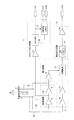
図1は、本発明の第1実施形態に係る振動式ジャイロセンサの構成を示すブロック図である。
図1において、振動式ジャイロセンサには、音叉型圧電振動片1、音叉型圧電振動片1を励振させる励振回路2、音叉型圧電振動片1が角速度ωで回転した時に振動Bに作用したコリオリ力Fを検出する検出回路9、検出回路9からの出力に基づいて角速度信号Joutを生成する検出出力回路14および音叉型圧電振動片1を励振させる励振信号S0に基づいて計時用のクロック信号を生成するクロック出力回路5が設けられている。
Hereinafter, a vibration type gyro sensor according to an embodiment of the present invention will be described with reference to the drawings.
FIG. 1 is a block diagram showing the configuration of the vibration gyro sensor according to the first embodiment of the present invention.
In FIG. 1, the vibration type gyro sensor includes a tuning fork type
図2は、図1の音叉型圧電振動片1の概略構成を示す斜視図である。
図2において、音叉型圧電振動片1には、例えば、X軸方向に延伸された1対の振動腕が設けられている。なお、音叉型圧電振動片1は、水晶などの圧電材料の平板を音叉型に切り出すことによって形成することができる。
そして、振動腕のZ軸方向に直交する面には、振動Bにコリオリ力Fが作用することによって生成された検出信号S2を出力する検出電極1cが設けられている。また、振動腕のY軸方向に直交する面には、音叉型圧電振動片1を駆動するための駆動信号S1を入力する駆動電極1aが設けられるとともに、検出信号S2をモニタするためのフィードバック信号S3を出力するフィードバック用電極1bが設けられている。
FIG. 2 is a perspective view showing a schematic configuration of the tuning-fork type piezoelectric vibrating
In FIG. 2, the tuning fork type piezoelectric vibrating
A
なお、音叉型圧電振動片1に用いられる材料としては、水晶の他、例えば、PZT(チタン酸ジルコン酸鉛)系圧電セラミック、ランガサイト(La3Ca5SiO14)、リン酸ガリウム(GaPo4)、タンタル酸リチウム(LiTaO3)またはBNT−BT−ST系無鉛圧電セラミックなどを用いることができる。また、音叉型圧電振動片1の共振周波数は、32.768×N(Nは正の整数)kHzに設定することが好ましい。
The material used for the tuning-fork type
そして、音叉型圧電振動片1の駆動電極1aに交流電圧を印加すると、振動腕がXY面内において屈曲振動する。そして、振動腕がXY面内において屈曲振動している状態で、音叉型圧電振動片1がX軸回りに角速度ωで回転すると、Z軸方向にコリオリ力Fが作用し、振動腕はXZ面内にも屈曲振動する。このため、検出電極1cには、圧電効果によりコリオリ力Fに対応した検出信号S2が発生する。ここで、コリオリ力Fは角速度ωに比例するため、検出電極1cに発生した検出信号S2を取り出すことにより、角速度ωを求めることができる。
When an AC voltage is applied to the
すなわち、図1において、発振回路3にて生成された励振信号S0は利得自動調整回路4にて利得調整され、音叉型圧電振動片1を駆動する駆動信号S1が出力される。そして、利得自動調整回路4から出力された駆動信号S1は図2の駆動電極1aに入力され、音叉型圧電振動片1の振動腕がXY面内において屈曲振動する。そして、この時の機械振動を電気信号に変換し、この電気信号をフィードバック用電極1bから取り出すことにより、フィードバック信号S3を発振回路3にフィードバックする。これにより、発振回路3を用いて発振ループを構成することが可能となり、音叉型圧電振動片1を音叉固有振動数で発振させることができる。また、利得自動調整回路4にて駆動信号S1の振幅制御を行うことにより、音叉固有振動振幅を常に一定に保つことが可能となり、感度を安定化させることができる。
That is, in FIG. 1, the excitation signal S0 generated by the
一方、音叉型圧電振動片1の検出電極1cに発生した検出信号S2は、IV変換アンプ10にて電流から電圧に変換された後、ACアンプ11にて増幅され、同期検波器13に入力される。また、同期検波器13には、駆動信号S1が90度位相シフタ12を介して入力され、ACアンプ11にて増幅された信号が発振回路3の基準位相に同期して検波される。すなわち、検出信号S2は、駆動信号S1の周波数を搬送波として角速度ωでAM変調された信号と等価であることから、駆動信号S1を基準信号として同期検波することにより、角速度ωを抽出することができる。
On the other hand, the detection signal S2 generated at the
そして、同期検波器13から出力された検波信号をローパスフィルタ15に通すことにより、検波信号に重畳された高周波成分を除去し、出力アンプ16を介して出力することにより角速度信号Joutを得ることができる。
また、発振回路3にて生成された励振信号S0は、バッファ6を介してデバイダー7に入力される。ここで、デバイダー7にはカウンタが設けられ、励振信号S0をデバイダー7にて分周することにより、計時用のクロック信号CKを生成することができる。例えば、音叉型圧電振動片1の共振周波数が32.768×kHzに設定されているものとすると、15個のカウンタを並べることにより、クロック信号CKとして1Hzの信号を生成することができ、1秒ごとのカウント動作を行わせることができる。
Then, by passing the detection signal output from the
The excitation signal S0 generated by the
また、コントロールロジック8には、クロック出力CKおよびコントロール信号CNが入力され、クロック信号CKに基づいて時刻およびカレンダ機能を有するRTCを構成することができる。そして、コントロールロジック8にて生成された時刻および日付情報は、データ信号Doutとして出力することができる。
ここで、振動式ジャイロセンサを励振させる励振信号S0に基づいて計時用のクロック信号CKを生成することにより、計時用のクロック信号CKを生成するために、振動式ジャイロセンサの音叉型圧電振動片1を用いることが可能となる。このため、時刻および日付情報を生成するために、振動式ジャイロセンサとは別にRTCモジュールを搭載する必要がなくなり、機器の大型化およびコストアップを抑制しつつ、時刻およびカレンダ機能および角速度検出機能の双方を持たせることが可能となる。
Further, the
Here, in order to generate the clock signal CK for clocking by generating the clock signal CK for clocking based on the excitation signal S0 for exciting the vibratory gyrosensor, the tuning-fork type piezoelectric vibrating piece of the vibratory gyrosensor is used. 1 can be used. For this reason, it is not necessary to install an RTC module separately from the vibration type gyro sensor in order to generate time and date information, and the time and calendar function and the angular velocity detection function can be reduced while suppressing the increase in size and cost of the device. It is possible to have both.
また、音叉型圧電振動片1に用いられる材料として水晶を用いることにより、音叉型圧電振動片1の共振周波数の精度を向上させることが可能となり、振動式ジャイロセンサから計時用のクロック信号CKを生成した場合においても、時刻精度を向上させることが可能となる。
また、音叉型圧電振動片1の共振周波数を32.768×NkHzに設定することにより、音叉型圧電振動片1の共振周波数が可聴帯域に入ることを防止しつつ、振動式ジャイロセンサの小型化を図ることが可能となるとともに、カウンタを並べて配置することで、1Hzの信号を生成することが可能となり、時刻情報を容易に生成することが可能となる。例えば、N=2、3、4・・・とした場合、それに対応してカウンタの個数を増加させることで、1Hzの信号を生成することが可能となる。
Further, by using quartz as a material used for the tuning fork type
Further, by setting the resonance frequency of the tuning fork type
また、上述した実施形態では、振動式ジャイロセンサに用いられる圧電振動子として二脚の音叉型圧電振動片1を用いる方法を例にとって説明したが、音叉型圧電振動片1以外にも、例えば、三または四脚またはH型の音叉型圧電振動子、あるいは音片型圧電振動子などを用いるようにしてもよい。
In the above-described embodiment, the method using the biped tuning fork type
図3は、本発明の第2実施形態に係る振動式ジャイロセンサの構成を示すブロック図である。
図3において、図2の検出回路9および検出出力回路14の代わりに、検出回路9´および検出出力回路14´が設けられている。そして、検出回路9´には、図2のIV変換アンプ10、ACアンプ11、90度位相シフタ12および同期検波器13の代わりに、IV変換アンプ10´、ACアンプ11´、90度位相シフタ12´および同期検波器13´が設けられている。また、検出出力回路14´には、図2のローパスフィルタ15および出力アンプ16の代わりに、ローパスフィルタ15´および出力アンプ16´が設けられている。
FIG. 3 is a block diagram showing the configuration of the vibration gyro sensor according to the second embodiment of the present invention.
3, a
ここで、IV変換アンプ10´、ACアンプ11´、90度位相シフタ12´、同期検波器13´ローパスフィルタ15´および出力アンプ16´にはアウトイネーブル信号OEが入力されている。そして、IV変換アンプ10´、ACアンプ11´、90度位相シフタ12´、同期検波器13´ローパスフィルタ15´および出力アンプ16´は、アウトイネーブル信号OEに基づいて動作を停止させることができる。
これにより、音叉型圧電振動片1を励振させる励振信号S0に基づいて計時用のクロック信号CKを生成することを可能としつつ、角速度の検出動作を停止させることが可能となる。このため、角速度検出機能が不要となった場合においても、省電力化を図りつつ、時刻およびカレンダ機能を発揮させることが可能となる。
Here, the out enable signal OE is input to the
Thereby, it becomes possible to generate the clock signal CK for timing based on the excitation signal S0 for exciting the tuning fork type
図4は、本発明の第3実施形態に係るナビゲーション装置の概略構成を示すブロック図である。
図4において、ナビゲーション装置には、自己の位置を検出するための位置検出器21、所定地域の地図データを取得する地図データ取得部26、ナビゲーション装置の各種操作を行う操作スイッチ27、自己の現在位置を地図上に重ねて表示可能な表示装置29およびこれらを連携させて全体的な制御を行う制御回路28が設けられている。
また、位置検出器21には、GPS受信機23、振動式ジャイロセンサ24および距離センサ25が設けられ、GPS受信機23には、GPS衛星からの電波を受信するアンテナ22および測位時のGPS信号の受信に用いるGPS衛星を捕捉する衛星捕捉部23aが設けられている。
FIG. 4 is a block diagram showing a schematic configuration of the navigation device according to the third embodiment of the present invention.
In FIG. 4, the navigation device includes a
The
ここで、GPS受信機23は、複数の人口衛星からの電波を受信することにより航法メッセージ(人口衛星の軌道情報および時刻情報)を取得し、地球上での自己の絶対位置を求めることができる。また、人口衛星からのドップラーシフト周波数を測定することにより、自己の速度を算出することができる。
また、振動式ジャイロセンサ24および距離センサ25を用いることにより、自己の進む方角および距離を算出することが可能となり、自立航法にて自己の現在位置を算出することができる。このため、トンネルなどでGPS信号が受信できなくなった場合においても、自己の現在位置を把握することが可能となるとともに、自己の現在位置の算出精度を向上させることが可能となる。
Here, the
Further, by using the vibration
すなわち、GPS受信機23は、人口衛星から送られた電波を受信すると、この電波を復調することにより、人口衛星の軌道情報および時刻情報を取得することができる。そして、人口衛星の軌道情報および時刻情報に基づいて人口衛星の位置および人口衛星からGPS受信機23までの電波の伝播時間が求まると、GPS受信機23の位置を未知数とする連立方程式を立てることにより、GPS受信機23の測位計算を行うことができる。
That is, when the
ここで、3個以上のGPS用衛星から受信される信号を演算処理して現在位置の緯度および経度を得るとともに、受信された信号に基づき標準時刻UTCを取得することができる。そして、地球全体をカバーするために、現在合計25個の人口衛星が打ち上げられ、地球の高度20000kmにある6個の軌道上を周回している。このため、GPS受信機23の現在の位置を求めるには、これら25個の人口衛星のうち追尾可能な少なくとも3個の人工衛星を捕捉する必要がある。
Here, the signals received from three or more GPS satellites are arithmetically processed to obtain the latitude and longitude of the current position, and the standard time UTC can be obtained based on the received signals. In order to cover the entire earth, a total of 25 artificial satellites have been launched and are orbiting six orbits at an altitude of 20000 km. Therefore, in order to obtain the current position of the
ここで、振動式ジャイロセンサ24として図1の構成を用いることができる。すなわち、振動式ジャイロセンサ24は、図1の発振回路3にて生成された励振信号S0に基づいて音叉型圧電振動片1を駆動する駆動信号S1を生成し、音叉型圧電振動片1の検出電極1cに発生した検出信号S2に基づいて角速度信号Joutを得ることができる。また、発振回路3にて生成された励振信号S0に基づいて計時用のクロック信号CKを生成することができる。そして、振動式ジャイロセンサ24から出力された角速度信号Joutは制御回路28に入力されるとともに、振動式ジャイロセンサ24から出力されたデータ信号Doutは、GPS受信機23および制御回路28に入力される。
Here, the configuration of FIG. 1 can be used as the
そして、振動式ジャイロセンサ24から出力されたデータ信号DoutがGPS受信機23に入力されると、衛星捕捉部23aは、データ信号Doutから抽出された現在時刻に基づいて現在時刻の可視衛星を推定することができる。そして、この推定結果に基づいて測位時のGPS信号の受信に用いる人工衛星を選択することにより、無駄な人工衛星を走査することなく、速やかに人工衛星を捕捉することを可能として、測位計算の立ち上がりを早めることができる。
When the data signal Dout output from the
また、振動式ジャイロセンサ24から出力された角速度信号Joutが制御回路28に入力されると、制御回路28は角速度信号Joutに基づいて方角を算出するとともに、距離センサ25から出力される距離を参照することにより、自立航法を行うことが可能となる。
さらに、振動式ジャイロセンサ24から出力されたデータ信号Doutが制御回路28に入力されると、目的地への誘導などにおいて、到着時刻予想などの演算を行うことができるそして、到着予想時刻が算出されると、自己の現在位置が含まれる地図を地図データ取得部26から取り出し、自己の現在位置がマーキングされた地図を到着予想時刻とともに表示装置29に表示させることができる。
When the angular velocity signal Jout output from the
Further, when the data signal Dout output from the vibration
これにより、振動式ジャイロセンサ24とは別にRTCモジュールをナビゲーション装置に搭載することなく、現在時刻の可視衛星を容易に判定することが可能となるとともに、時刻情報を生成することが可能となる。このため、ナビゲーション装置の大型化および高価格化を抑制しつつ、時刻およびカレンダ機能および角速度検出機能の双方を持たせることが可能となるとともに、測位時のGPS信号の受信に用いる衛星の捕捉時間を短縮することが可能となる。
This makes it possible to easily determine the visible satellite at the current time and to generate time information without mounting an RTC module separately from the
図5は、本発明の第4実施形態に係る撮像装置の概略構成を示すブロック図である。
図5において、レンズ31を介して入射した被写体の光学像はCCD33の撮像面上に結像される。そして、CCD33の撮像面上に結像された光学像は画像信号に光電変換され、A/Dコンバータ34にてデジタル化される。そして、デジタル化された画像信号は、画像処理回路35にて画像処理された後、画像メモリ36に記憶されるとともに、表示部41に表示される。また、画像処理回路35にて画像処理された信号は、記録データインターフェース39を介して記録媒体38に送られ、記録媒体38に保存することができる。なお、DSCの場合、記録データインターフェース39としてカードインターフェース、記録媒体38としてメモリカードなどを用いることができる。また、DVCの場合、記録データインターフェース39および記録媒体38として磁気テープなどを用いることができる。
FIG. 5 is a block diagram showing a schematic configuration of an imaging apparatus according to the fourth embodiment of the present invention.
In FIG. 5, the optical image of the subject incident through the
ここで、全体制御部42には振動式ジャイロセンサ40が接続され、振動式ジャイロセンサ40として図1の構成を用いることができる。すなわち、振動式ジャイロセンサ40は、図1の発振回路3にて生成された励振信号S0に基づいて音叉型圧電振動片1を駆動する駆動信号S1を生成し、音叉型圧電振動片1の検出電極1cに発生した検出信号S2に基づいて角速度信号Joutを得ることができる。また、発振回路3にて生成された励振信号S0に基づいて計時用のクロック信号CKを生成することができる。そして、振動式ジャイロセンサ40から出力された角速度信号Joutおよびデータ信号Doutは全体制御部42に入力される。
Here, a
そして、全体制御部42は、振動式ジャイロセンサ40から出力された角速度信号Joutに基づいてアクチュエータ32を制御し、手振れが打ち消されるようにレンズ31を動かすことにより、手振れ補正を行うことが可能となる。あるいは、全体制御部42は、振動式ジャイロセンサ40から出力された角速度信号Joutに基づいて、画像メモリ36に記憶された画像の切り出し範囲を制御することにより、手振れが打ち消された画像を表示部41に表示させたり、記録媒体38に保存させたりすることができる。
The
また、振動式ジャイロセンサ40から出力されたデータ信号Doutが全体制御部42に入力されると、全体制御部42は、時刻および日付情報が取り入れられた画像を表示部41に表示させたり、記録媒体38に保存させたりすることができる。
これにより、振動式ジャイロセンサ40で検出された検出信号S2に基づいて手振れ補正を行うことが可能となり、手振れと被写体動作の判別を容易化することが可能となるとともに、振動式ジャイロセンサ40とは別にRTCモジュールを撮像装置に搭載することなく、時刻および日付情報を生成することが可能となる。このため、撮像装置の大型化および高価格化を抑制しつつ、時刻およびカレンダ機能を持たせることが可能となるとともに、手振れ補正を精度よく行うことが可能となる。
When the data signal Dout output from the
Accordingly, it is possible to perform camera shake correction based on the detection signal S2 detected by the
また、操作部37にて、撮像装置の電源をオン/オフしたり、レンズ31のズーミングを行ったり、撮像タイミングを決定したり、手振れ補正をオン/オフしたりすることができる。
そして、手振れ補正をオフする場合、振動式ジャイロセンサ24として図3の構成を用いることにより、音叉型圧電振動片1を励振させる励振信号S0に基づいてデータ信号Doutを生成することを可能としつつ、角速度の検出動作を停止させることが可能となる。このため、時刻および日付情報が取り入れられた画像を表示部41に表示させたり、記録媒体38に保存させたりすることを可能としつつ、省電力化を図ることが可能となる。
Further, the
When the camera shake correction is turned off, the data signal Dout can be generated based on the excitation signal S0 for exciting the tuning-fork type
図6は、本発明の第5実施形態に係る振動式ジャイロセンサの構成を示すブロック図である。
図6において、振動式ジャイロセンサには、静電振動子51、静電振動子51を励振させる励振回路52、静電振動子51が角速度ωで回転した時に振動Bに作用したコリオリ力Fを検出する検出回路59、検出回路59からの出力に基づいて角速度信号Jout2を生成する検出出力回路64および静電振動子51を励振させる励振信号S10に基づいて計時用のクロック信号を生成するクロック出力回路55が設けられている。
FIG. 6 is a block diagram showing a configuration of a vibration type gyro sensor according to a fifth embodiment of the present invention.
In FIG. 6, the vibration type gyro sensor includes an
図7は、図6の静電振動子51の構成を示す斜視図である。なお、図7の例では、静電振動子51として表面マイクロマシン加工振動子を用いた場合を示す。
図7において、静電振動子51には、質量体として作用するボディ74が設けられるとともに、ボディ74を支持する基板70が設けられている。ここで、基板70上には、支持アンカー71a〜71dが形成されるとともに、ボディ74の四隅には、たわみ部73a〜73dがそれぞれ形成されている。そして、ボディ74は、たわみ部73a〜73dを介して支持アンカー71a〜71dに接続され、基板70に対して水平方向に揺動できるように基板70上に懸垂されている。ここで、ボディ74の1対の辺には、ボディ74の振動方向に突き出るように可動フィンガ76b、76cがそれぞれ接続され、ボディ74の残りの1対の辺には、コリオリ力Fの検出方向に突き出るように可動フィンガ76a、76dがそれぞれ接続されている。
FIG. 7 is a perspective view showing the configuration of the
In FIG. 7, the
また、ボディ74の周囲には、ボディ74の各辺にそれぞれ対向配置された支持体72a〜72dが基板70上に形成されている。そして、支持体72a〜72dには、可動フィンガ76a〜76dとそれぞれかみ合うように固定フィンガ75a〜75dがそれぞれ接続されている。そして、支持体72bには、ボディ74を駆動するための駆動信号S11を入力する駆動端子A1が設けられるとともに、支持体72cには、検出信号S12、S12´をモニタするためのフィードバック信号S13を出力するフィードバック端子A1´が設けられている。また、支持体72a、72dには、振動Bにコリオリ力Fが作用することによって発生した差動容量を検出信号S12、S12´としてそれぞれ出力する検出端子A2、A2´がそれぞれ設けられている。なお、静電振動子51の共振周波数は、32.768×N(Nは正の整数)kHzに設定することが好ましい。
Further, around the
そして、静電振動子51の駆動端子A1に交流電圧を印加すると、ボディ74が駆動軸KJに沿って揺動する。そして、ボディ74が駆動軸KJに沿って揺動している状態で、静電振動子51が回転軸RJの回りに角速度ωで回転すると、検出軸DJの方向にコリオリ力Fが作用し、ボディ74は検出軸DJに沿って揺動する。このため、固定フィンガ75aと可動フィンガ76aとの間の容量および固定フィンガ75dと可動フィンガ76dとの間の容量がそれぞれ変化し、検出端子A2、A2´には、コリオリ力Fに対応した検出信号S12、S12´が発生する。ここで、コリオリ力Fは角速度ωに比例するため、検出端子A2、A2´に発生した検出信号S12、S12´を取り出すことにより、角速度ωを求めることができる。
When an AC voltage is applied to the drive terminal A1 of the
すなわち、図6において、発振回路53にて生成された励振信号S10は利得自動調整回路54にて利得調整され、静電振動子51を駆動する駆動信号S1が出力される。そして、利得自動調整回路54から出力された駆動信号S11は駆動端子A1に入力され、静電振動子51のボディ74が駆動軸KJに沿って揺動する。そして、この時の機械振動を電気信号に変換し、この電気信号をフィードバック端子A1´から取り出すことにより、フィードバック信号S13を発振回路53にフィードバックする。これにより、発振回路53を用いて発振ループを構成することが可能となり、静電振動子51をボディ74の固有振動数で発振させることができる。また、利得自動調整回路54にて駆動信号S11の振幅制御を行うことにより、ボディ74の固有振動振幅を常に一定に保つことが可能となり、感度を安定化させることができる。
That is, in FIG. 6, the excitation signal S10 generated by the
一方、静電振動子51の検出端子A2、A2´にそれぞれ発生した検出信号S12、S12´は、IV変換アンプ60、60´にて電流から電圧にそれぞれ変換された後、差動増幅器61にて差動増幅され、同期検波器63に入力される。また、同期検波器63には、駆動信号S11が90度位相シフタ62を介して入力され、ACアンプ61にて増幅された信号が発振回路53の基準位相に同期して検波される。すなわち、検出信号S12は、駆動信号S11の周波数を搬送波として角速度ωでAM変調された信号と等価であることから、駆動信号S11を基準信号として同期検波することにより、角速度ωを抽出することができる。
On the other hand, the detection signals S12 and S12 ′ generated at the detection terminals A2 and A2 ′ of the
そして、同期検波器63から出力された検波信号をローパスフィルタ55に通すことにより、検波信号に重畳された高周波成分を除去し、出力アンプ56を介して出力することにより角速度信号Jout2を得ることができる。
また、発振回路53にて生成された励振信号S10は、バッファ56を介してデバイダー57に入力される。ここで、デバイダー57にはカウンタが設けられ、励振信号S10をデバイダー57にて分周することにより、計時用のクロック信号CK2を生成することができる。例えば、静電振動子51の共振周波数が32.768×kHzに設定されているものとすると、15個のカウンタを並べることにより、クロック信号CK2として1Hzの信号を生成することができ、1秒ごとのカウント動作を行わせることができる。
Then, by passing the detection signal output from the
Further, the
また、コントロールロジック58には、クロック出力CK2およびコントロール信号CN2が入力され、クロック信号CK2に基づいて時刻およびカレンダ機能を有するRTCを構成することができる。そして、コントロールロジック58にて生成された時刻および日付情報は、データ信号Dout2として出力することができる。
Further, the clock output CK2 and the control signal CN2 are input to the
ここで、振動式ジャイロセンサを励振させる励振信号S10に基づいて計時用のクロック信号CK2を生成することにより、計時用のクロック信号CK2を生成するために、振動式ジャイロセンサの静電振動子51を用いることが可能となる。このため、時刻および日付情報を生成するために、振動式ジャイロセンサとは別にRTCモジュールを搭載する必要がなくなり、機器の大型化およびコストアップを抑制しつつ、時刻およびカレンダ機能および角速度検出機能の双方を持たせることが可能となる。
また、静電振動子51として表面マイクロマシン加工振動子を用いることにより、微細加工技術を用いることで振動式ジャイロセンサを構成することができ、振動式ジャイロセンサの小型化を図ることができる。
Here, in order to generate the clock signal CK2 for clocking by generating the clock signal CK2 for clocking based on the excitation signal S10 for exciting the vibratory gyrosensor, the
Further, by using a surface micromachined vibrator as the
1 音叉型圧電振動片、1a 駆動電極、1b フィードバック用電極、1c 検出電極、2、52 励振回路、3、53 発振回路、4、54 利得自動調整回路、5、55 クロック出力回路、6、56 バッファ、7、57 デバイダー、8、58 コントロールロジック、9、9´、59 検出回路、10、10´、60、60´ IV変換アンプ、11、11´ ACアンプ、12、12´ 90度位相シフタ、13、13´、63 同期検波器、14、14´、64 検出出力回路、15、15´、55 ローパスフィルタ、16、16´、56 出力アンプ、CK、CK2 クロック信号、CN、CN2 コントロール信号、Dout、Dout2 データ信号、Jout、Jout2 角速度信号、OE アウトイネーブル信号、21 位置検出器、22 アンテナ、23 GPS受信機、23a 衛星捕捉部、24、40 振動式ジャイロセンサ、25 距離センサ、26 地図データ取得部、27 操作スイッチ、28 制御回路、29 表示装置、31 レンズ、32 アクチュエータ、33 CCD、34 A/Dコンバータ、35 画像処理回路、36 画像メモリ、37 操作部、38 記録媒体、39 記録データインターフェース、41 表示部、42 全体制御部、51 静電振動子、61 差動増幅器、70 基板、71a〜71d 支持アンカー、72a〜72d 支持体、73a〜73d たわみ部、74 ボディ、75a〜75d 固定フィンガ、76a〜76d 可動フィンガ DESCRIPTION OF SYMBOLS 1 Tuning fork type piezoelectric vibrating piece, 1a Drive electrode, 1b Feedback electrode, 1c Detection electrode, 2,52 Excitation circuit, 3,53 Oscillation circuit, 4,54 Gain automatic adjustment circuit, 5,55 Clock output circuit, 6,56 Buffer, 7, 57 Divider, 8, 58 Control logic, 9, 9 ', 59 Detection circuit, 10, 10', 60, 60 'IV conversion amplifier, 11, 11' AC amplifier, 12, 12 '90 degree phase shifter , 13, 13 ', 63 Synchronous detector, 14, 14', 64 Detection output circuit, 15, 15 ', 55 Low pass filter, 16, 16', 56 Output amplifier, CK, CK2 Clock signal, CN, CN2 Control signal , Dout, Dout2 data signal, Jout, Jout2 angular velocity signal, OE out enable signal, 21 position detector 22 antennas, 23 GPS receivers, 23a satellite acquisition unit, 24, 40 vibration gyro sensor, 25 distance sensor, 26 map data acquisition unit, 27 operation switch, 28 control circuit, 29 display device, 31 lens, 32 actuator, 33 CCD, 34 A / D converter, 35 image processing circuit, 36 image memory, 37 operation unit, 38 recording medium, 39 recording data interface, 41 display unit, 42 overall control unit, 51 electrostatic vibrator, 61 differential amplifier, 70 Substrate, 71a-71d Support anchor, 72a-72d Support, 73a-73d Deflection, 74 Body, 75a-75d Fixed finger, 76a-76d Movable finger
Claims (12)
前記振動子の励振方向と直角の方向に作用するコリオリ力を検出する検出手段と、
前記振動子を励振させる励振信号に基づいて計時用のクロック信号を生成するクロック生成手段とを備えることを特徴とする振動式ジャイロセンサ。 Excitation means for exciting the vibrator;
Detection means for detecting Coriolis force acting in a direction perpendicular to the excitation direction of the vibrator;
A vibration type gyro sensor comprising: clock generation means for generating a clock signal for timing based on an excitation signal for exciting the vibrator.
基板に対して水平方向に揺動できるように前記基板上に懸垂されたボディと、
前記基板に対して水平な第1の方向に突き出るように前記ボディに設けられた第1の可動フィンガと、
前記第1の方向と直交する方向に突き出るように前記ボディに設けられた第2の可動フィンガと、
前記第1の可動フィンガとかみ合うように前記基板に固定された第1の固定フィンガと、
前記第2の可動フィンガとかみ合うように前記基板に固定された第2の固定フィンガとを備えることを特徴とする請求項6記載の振動式ジャイロセンサ。 The surface micromachined vibrator is
A body suspended on the substrate so as to be able to swing horizontally with respect to the substrate;
A first movable finger provided on the body so as to protrude in a first direction horizontal to the substrate;
A second movable finger provided on the body so as to protrude in a direction perpendicular to the first direction;
A first fixed finger fixed to the substrate so as to engage with the first movable finger;
The vibration type gyro sensor according to claim 6, further comprising a second fixed finger fixed to the substrate so as to be engaged with the second movable finger.
時刻情報を出力する時刻情報出力手段と、
日付情報を出力する日付情報出力手段とを備えることを特徴とする請求項2〜7のいずれか1項記載の振動式ジャイロセンサ。 The clock generation means includes
Time information output means for outputting time information;
The vibration type gyro sensor according to claim 2, further comprising date information output means for outputting date information.
所定地域の地図データを取得する地図データ取得手段と、
振動子を励振させる励振信号に基づいて計時用のクロック信号を生成する振動式ジャイロセンサと、
前記GPS受信機で受信されたGPS信号または前記振動式ジャイロセンサで検出された検出信号に基づいて測位を行う測位手段と、
前記振動式ジャイロセンサから出力されたクロック信号に基づいて時刻または日付情報を生成する時間情報生成手段と、
前記時間情報生成手段にて生成された時刻情報に基づいて前記GPS衛星を捕捉させる衛星捕捉手段とを備えることを特徴とするナビゲーション装置。 A GPS receiver for receiving GPS signals transmitted from GPS satellites;
Map data acquisition means for acquiring map data of a predetermined area;
A vibration gyro sensor that generates a clock signal for timing based on an excitation signal for exciting the vibrator;
Positioning means for performing positioning based on a GPS signal received by the GPS receiver or a detection signal detected by the vibration gyro sensor;
Time information generating means for generating time or date information based on a clock signal output from the vibration gyro sensor;
A navigation device comprising satellite capturing means for capturing the GPS satellite based on the time information generated by the time information generating means.
振動子を励振させる励振信号に基づいて計時用のクロック信号を生成する振動式ジャイロセンサと、
前記振動式ジャイロセンサで検出された検出信号に基づいて前記撮像素子で撮像された画像の手振れ補正を行う手振れ補正手段と、
前記振動式ジャイロセンサから出力されたクロック信号に基づいて時刻または日付情報を生成する時間情報生成手段とを備えることを特徴とする撮像装置。 An image sensor for imaging;
A vibration gyro sensor that generates a clock signal for timing based on an excitation signal for exciting the vibrator;
A camera shake correction unit that performs camera shake correction of an image captured by the image sensor based on a detection signal detected by the vibration gyro sensor;
An image pickup apparatus comprising: time information generation means for generating time or date information based on a clock signal output from the vibration gyro sensor.
Priority Applications (2)
| Application Number | Priority Date | Filing Date | Title |
|---|---|---|---|
| JP2004299939A JP2005241625A (en) | 2004-01-27 | 2004-10-14 | Clock-generating device, vibration type gyro sensor, navigation device, imaging apparatus, and electronic device |
| US11/043,711 US7258009B2 (en) | 2004-01-27 | 2005-01-26 | Clock generating device, vibration type gyro sensor, navigation device, imaging device, and electronic apparatus |
Applications Claiming Priority (2)
| Application Number | Priority Date | Filing Date | Title |
|---|---|---|---|
| JP2004018377 | 2004-01-27 | ||
| JP2004299939A JP2005241625A (en) | 2004-01-27 | 2004-10-14 | Clock-generating device, vibration type gyro sensor, navigation device, imaging apparatus, and electronic device |
Publications (2)
| Publication Number | Publication Date |
|---|---|
| JP2005241625A true JP2005241625A (en) | 2005-09-08 |
| JP2005241625A5 JP2005241625A5 (en) | 2007-07-26 |
Family
ID=34797803
Family Applications (1)
| Application Number | Title | Priority Date | Filing Date |
|---|---|---|---|
| JP2004299939A Pending JP2005241625A (en) | 2004-01-27 | 2004-10-14 | Clock-generating device, vibration type gyro sensor, navigation device, imaging apparatus, and electronic device |
Country Status (2)
| Country | Link |
|---|---|
| US (1) | US7258009B2 (en) |
| JP (1) | JP2005241625A (en) |
Cited By (2)
| Publication number | Priority date | Publication date | Assignee | Title |
|---|---|---|---|---|
| JP2008107324A (en) * | 2006-09-27 | 2008-05-08 | Citizen Holdings Co Ltd | Detecting method of piezoelectric element, oscillator, and oscillation gyroscope |
| JP2018161379A (en) * | 2017-03-27 | 2018-10-18 | 京セラ株式会社 | Sensor-incorporating ball and measurement system |
Families Citing this family (32)
| Publication number | Priority date | Publication date | Assignee | Title |
|---|---|---|---|---|
| JP2005217903A (en) * | 2004-01-30 | 2005-08-11 | Seiko Epson Corp | Tuning fork type oscillating piece and electronic apparatus |
| KR100985364B1 (en) | 2004-04-30 | 2010-10-04 | 힐크레스트 래보래토리스, 인크. | Free space pointing device and method |
| US8629836B2 (en) | 2004-04-30 | 2014-01-14 | Hillcrest Laboratories, Inc. | 3D pointing devices with orientation compensation and improved usability |
| WO2006058129A2 (en) | 2004-11-23 | 2006-06-01 | Hillcrest Laboratories, Inc. | Semantic gaming and application transformation |
| JP2007057272A (en) * | 2005-08-22 | 2007-03-08 | Nippon Dempa Kogyo Co Ltd | Tuning fork crystal oscillator having angular velocity detection mechanism |
| JP5365173B2 (en) * | 2008-02-29 | 2013-12-11 | セイコーエプソン株式会社 | Physical quantity measuring device and electronic device |
| US8797279B2 (en) | 2010-05-25 | 2014-08-05 | MCube Inc. | Analog touchscreen methods and apparatus |
| US8928602B1 (en) | 2009-03-03 | 2015-01-06 | MCube Inc. | Methods and apparatus for object tracking on a hand-held device |
| US8476129B1 (en) | 2010-05-24 | 2013-07-02 | MCube Inc. | Method and structure of sensors and MEMS devices using vertical mounting with interconnections |
| US8823007B2 (en) | 2009-10-28 | 2014-09-02 | MCube Inc. | Integrated system on chip using multiple MEMS and CMOS devices |
| US8710597B1 (en) | 2010-04-21 | 2014-04-29 | MCube Inc. | Method and structure for adding mass with stress isolation to MEMS structures |
| US8477473B1 (en) | 2010-08-19 | 2013-07-02 | MCube Inc. | Transducer structure and method for MEMS devices |
| US8421082B1 (en) | 2010-01-19 | 2013-04-16 | Mcube, Inc. | Integrated CMOS and MEMS with air dielectric method and system |
| US8553389B1 (en) | 2010-08-19 | 2013-10-08 | MCube Inc. | Anchor design and method for MEMS transducer apparatuses |
| US9709509B1 (en) | 2009-11-13 | 2017-07-18 | MCube Inc. | System configured for integrated communication, MEMS, Processor, and applications using a foundry compatible semiconductor process |
| US8637943B1 (en) | 2010-01-04 | 2014-01-28 | MCube Inc. | Multi-axis integrated MEMS devices with CMOS circuits and method therefor |
| US8584521B1 (en) * | 2010-01-19 | 2013-11-19 | MCube Inc. | Accurate gyroscope device using MEMS and quartz |
| US8936959B1 (en) | 2010-02-27 | 2015-01-20 | MCube Inc. | Integrated rf MEMS, control systems and methods |
| US8794065B1 (en) | 2010-02-27 | 2014-08-05 | MCube Inc. | Integrated inertial sensing apparatus using MEMS and quartz configured on crystallographic planes |
| US8021185B1 (en) * | 2010-03-10 | 2011-09-20 | Hubbell Incorporated | Surge snap-on module assembly |
| US8367522B1 (en) | 2010-04-08 | 2013-02-05 | MCube Inc. | Method and structure of integrated micro electro-mechanical systems and electronic devices using edge bond pads |
| US8928696B1 (en) | 2010-05-25 | 2015-01-06 | MCube Inc. | Methods and apparatus for operating hysteresis on a hand held device |
| US8652961B1 (en) | 2010-06-18 | 2014-02-18 | MCube Inc. | Methods and structure for adapting MEMS structures to form electrical interconnections for integrated circuits |
| US8869616B1 (en) | 2010-06-18 | 2014-10-28 | MCube Inc. | Method and structure of an inertial sensor using tilt conversion |
| US8993362B1 (en) | 2010-07-23 | 2015-03-31 | MCube Inc. | Oxide retainer method for MEMS devices |
| US8723986B1 (en) | 2010-11-04 | 2014-05-13 | MCube Inc. | Methods and apparatus for initiating image capture on a hand-held device |
| US8969101B1 (en) | 2011-08-17 | 2015-03-03 | MCube Inc. | Three axis magnetic sensor device and method using flex cables |
| DE102011089813A1 (en) * | 2011-12-23 | 2013-06-27 | Continental Teves Ag & Co. Ohg | Frequency transmitter arrangement |
| CN105830392B (en) * | 2013-10-23 | 2020-07-31 | 瑞典爱立信有限公司 | Method, node and computer program for enabling resource component allocation |
| CN104868847A (en) * | 2015-04-09 | 2015-08-26 | 中宇嘉华(北京)科技有限公司 | High-performance low-power-consumption real time clock |
| CN105141190B (en) * | 2015-07-20 | 2017-11-17 | 瑞声光电科技(常州)有限公司 | Driven by vibrating motors method |
| GB2576639B8 (en) * | 2018-08-17 | 2021-07-07 | Schlumberger Technology Bv | Resonating sensor for high-pressure and high-temperature environments |
Citations (9)
| Publication number | Priority date | Publication date | Assignee | Title |
|---|---|---|---|---|
| JPS51151579A (en) * | 1975-06-09 | 1976-12-27 | Camin Ind Corp | Voice indication clock |
| JPS52135774A (en) * | 1976-05-08 | 1977-11-14 | Citizen Watch Co Ltd | Digital chronograph |
| JPH1047970A (en) * | 1996-08-08 | 1998-02-20 | Matsushita Electric Ind Co Ltd | Angular velocity sensor element and angular velocity detector |
| JPH10170271A (en) * | 1996-12-09 | 1998-06-26 | Toyota Motor Corp | Angular velocity detector |
| JPH11351874A (en) * | 1997-05-07 | 1999-12-24 | Denso Corp | Angular velocity sensor and its adjustment method |
| JP2002162230A (en) * | 2000-09-15 | 2002-06-07 | Bei Technologies Inc | Inertial velocity sensor provided with improved tuning fork drive and method |
| JP2002188925A (en) * | 2000-09-15 | 2002-07-05 | Bei Technologies Inc | Inertial rate sensor with improved-type clock means and its method |
| JP2002311173A (en) * | 2001-04-13 | 2002-10-23 | Yazaki Corp | Electronic clock, method and program for correcting time error of the same |
| JP2003270371A (en) * | 2002-03-13 | 2003-09-25 | Toshiba Corp | Clock device in computer system |
Family Cites Families (4)
| Publication number | Priority date | Publication date | Assignee | Title |
|---|---|---|---|---|
| JP3304027B2 (en) | 1995-04-19 | 2002-07-22 | 松下電器産業株式会社 | GPS receiver |
| EP1094297B1 (en) * | 1999-10-20 | 2005-07-27 | Murata Manufacturing Co., Ltd. | Method of measuring angular velocity and vibrating gyroscope |
| JP2001292367A (en) | 2000-04-06 | 2001-10-19 | Minolta Co Ltd | Imaging apparatus and image pickup method |
| JP3943870B2 (en) | 2001-06-21 | 2007-07-11 | 株式会社デンソー | Navigation system |
-
2004
- 2004-10-14 JP JP2004299939A patent/JP2005241625A/en active Pending
-
2005
- 2005-01-26 US US11/043,711 patent/US7258009B2/en not_active Expired - Fee Related
Patent Citations (9)
| Publication number | Priority date | Publication date | Assignee | Title |
|---|---|---|---|---|
| JPS51151579A (en) * | 1975-06-09 | 1976-12-27 | Camin Ind Corp | Voice indication clock |
| JPS52135774A (en) * | 1976-05-08 | 1977-11-14 | Citizen Watch Co Ltd | Digital chronograph |
| JPH1047970A (en) * | 1996-08-08 | 1998-02-20 | Matsushita Electric Ind Co Ltd | Angular velocity sensor element and angular velocity detector |
| JPH10170271A (en) * | 1996-12-09 | 1998-06-26 | Toyota Motor Corp | Angular velocity detector |
| JPH11351874A (en) * | 1997-05-07 | 1999-12-24 | Denso Corp | Angular velocity sensor and its adjustment method |
| JP2002162230A (en) * | 2000-09-15 | 2002-06-07 | Bei Technologies Inc | Inertial velocity sensor provided with improved tuning fork drive and method |
| JP2002188925A (en) * | 2000-09-15 | 2002-07-05 | Bei Technologies Inc | Inertial rate sensor with improved-type clock means and its method |
| JP2002311173A (en) * | 2001-04-13 | 2002-10-23 | Yazaki Corp | Electronic clock, method and program for correcting time error of the same |
| JP2003270371A (en) * | 2002-03-13 | 2003-09-25 | Toshiba Corp | Clock device in computer system |
Cited By (2)
| Publication number | Priority date | Publication date | Assignee | Title |
|---|---|---|---|---|
| JP2008107324A (en) * | 2006-09-27 | 2008-05-08 | Citizen Holdings Co Ltd | Detecting method of piezoelectric element, oscillator, and oscillation gyroscope |
| JP2018161379A (en) * | 2017-03-27 | 2018-10-18 | 京セラ株式会社 | Sensor-incorporating ball and measurement system |
Also Published As
| Publication number | Publication date |
|---|---|
| US20050160813A1 (en) | 2005-07-28 |
| US7258009B2 (en) | 2007-08-21 |
Similar Documents
| Publication | Publication Date | Title |
|---|---|---|
| JP2005241625A (en) | Clock-generating device, vibration type gyro sensor, navigation device, imaging apparatus, and electronic device | |
| US8618889B2 (en) | Oscillation drive device, physical quantity measurement device and electronic apparatus | |
| US9103674B2 (en) | Sensor element, method for manufacturing sensor element, sensor device, and electronic apparatus | |
| JPWO2006075764A1 (en) | Vibrating gyroscope | |
| CN101236082B (en) | Vibration gyro sensor, control circuit, and electronic apparatus | |
| KR20060099466A (en) | Vibrating gyro element | |
| JP4206975B2 (en) | Vibrator, electronic device, and frequency adjustment method for vibrator | |
| US9091542B2 (en) | Sensor element, method for manufacturing sensor element, sensor device, and electronic apparatus | |
| JP2007232710A (en) | Oscillator for oscillating gyroscope | |
| JP3751745B2 (en) | Vibrator, vibratory gyroscope and measuring method of rotational angular velocity | |
| JP4012578B2 (en) | Vibrating gyro | |
| JPH1164005A (en) | Piezoelectric rotation sensor for biaxial simultaneous measurement and its measuring circuit | |
| JP5050448B2 (en) | Angular velocity sensor and electronic device | |
| KR20130074373A (en) | Gyro sensor drive circuit, gyro sensor system and method for driving gyro sensor | |
| JP4930253B2 (en) | Drive device, physical quantity measuring device and electronic device | |
| JP3720563B2 (en) | Vibrator, vibratory gyroscope and measuring method of rotational angular velocity | |
| JP2009128020A (en) | Piezoelectric vibration gyroscope using tuning fork type piezoelectric single crystal vibrator | |
| JP2003107549A (en) | Mounting device for vibration detecting means, and vibration-proof system | |
| JPH1038580A (en) | Angular velocity detecting equipment | |
| JP3028999B2 (en) | Vibrating gyro | |
| JP2004101255A (en) | Piezoelectric vibration gyroscopic sensor | |
| JPH10332381A (en) | Angular speed detector | |
| JPH10170271A (en) | Angular velocity detector | |
| JP2006064613A (en) | Gyroscopic sensor and electronic device | |
| JPH07128069A (en) | Angular speed sensor |
Legal Events
| Date | Code | Title | Description |
|---|---|---|---|
| A521 | Request for written amendment filed |
Free format text: JAPANESE INTERMEDIATE CODE: A523 Effective date: 20070607 |
|
| A621 | Written request for application examination |
Free format text: JAPANESE INTERMEDIATE CODE: A621 Effective date: 20070607 |
|
| A977 | Report on retrieval |
Free format text: JAPANESE INTERMEDIATE CODE: A971007 Effective date: 20100115 |
|
| A131 | Notification of reasons for refusal |
Free format text: JAPANESE INTERMEDIATE CODE: A131 Effective date: 20100126 |
|
| A521 | Request for written amendment filed |
Free format text: JAPANESE INTERMEDIATE CODE: A821 Effective date: 20100129 |
|
| RD04 | Notification of resignation of power of attorney |
Free format text: JAPANESE INTERMEDIATE CODE: A7424 Effective date: 20100129 |
|
| A521 | Request for written amendment filed |
Free format text: JAPANESE INTERMEDIATE CODE: A523 Effective date: 20100326 |
|
| RD03 | Notification of appointment of power of attorney |
Free format text: JAPANESE INTERMEDIATE CODE: A7423 Effective date: 20100326 |
|
| A02 | Decision of refusal |
Free format text: JAPANESE INTERMEDIATE CODE: A02 Effective date: 20100713 |