JP2007526652A - 半導体デバイス製造の間のstiディボット形成を減少する方法 - Google Patents
半導体デバイス製造の間のstiディボット形成を減少する方法 Download PDFInfo
- Publication number
- JP2007526652A JP2007526652A JP2007501861A JP2007501861A JP2007526652A JP 2007526652 A JP2007526652 A JP 2007526652A JP 2007501861 A JP2007501861 A JP 2007501861A JP 2007501861 A JP2007501861 A JP 2007501861A JP 2007526652 A JP2007526652 A JP 2007526652A
- Authority
- JP
- Japan
- Prior art keywords
- nitride
- stop layer
- layer
- polish stop
- semiconductor substrate
- Prior art date
- Legal status (The legal status is an assumption and is not a legal conclusion. Google has not performed a legal analysis and makes no representation as to the accuracy of the status listed.)
- Pending
Links
- 239000004065 semiconductor Substances 0.000 title claims description 28
- 238000000034 method Methods 0.000 title claims description 25
- 238000004519 manufacturing process Methods 0.000 title claims description 10
- 230000015572 biosynthetic process Effects 0.000 title abstract description 8
- 150000004767 nitrides Chemical class 0.000 claims abstract description 40
- 238000005498 polishing Methods 0.000 claims description 28
- 239000000758 substrate Substances 0.000 claims description 24
- 239000011810 insulating material Substances 0.000 claims description 10
- 238000002955 isolation Methods 0.000 claims description 7
- 239000012535 impurity Substances 0.000 claims description 6
- 238000005530 etching Methods 0.000 claims description 4
- 150000002500 ions Chemical class 0.000 claims description 3
- 238000004140 cleaning Methods 0.000 abstract description 11
- 230000000873 masking effect Effects 0.000 abstract description 6
- 238000002513 implantation Methods 0.000 abstract description 4
- 239000002019 doping agent Substances 0.000 abstract description 2
- 239000010410 layer Substances 0.000 description 46
- 229910052581 Si3N4 Inorganic materials 0.000 description 18
- HQVNEWCFYHHQES-UHFFFAOYSA-N silicon nitride Chemical compound N12[Si]34N5[Si]62N3[Si]51N64 HQVNEWCFYHHQES-UHFFFAOYSA-N 0.000 description 18
- 238000005468 ion implantation Methods 0.000 description 8
- 238000007796 conventional method Methods 0.000 description 7
- KRHYYFGTRYWZRS-UHFFFAOYSA-N Fluorane Chemical compound F KRHYYFGTRYWZRS-UHFFFAOYSA-N 0.000 description 4
- VYPSYNLAJGMNEJ-UHFFFAOYSA-N Silicium dioxide Chemical compound O=[Si]=O VYPSYNLAJGMNEJ-UHFFFAOYSA-N 0.000 description 3
- XUIMIQQOPSSXEZ-UHFFFAOYSA-N Silicon Chemical compound [Si] XUIMIQQOPSSXEZ-UHFFFAOYSA-N 0.000 description 3
- 238000012986 modification Methods 0.000 description 3
- 230000004048 modification Effects 0.000 description 3
- 238000012545 processing Methods 0.000 description 3
- 229910052710 silicon Inorganic materials 0.000 description 3
- 239000010703 silicon Substances 0.000 description 3
- 229910052814 silicon oxide Inorganic materials 0.000 description 3
- 238000013459 approach Methods 0.000 description 2
- 230000003647 oxidation Effects 0.000 description 2
- 238000007254 oxidation reaction Methods 0.000 description 2
- 229910021332 silicide Inorganic materials 0.000 description 2
- FVBUAEGBCNSCDD-UHFFFAOYSA-N silicide(4-) Chemical group [Si-4] FVBUAEGBCNSCDD-UHFFFAOYSA-N 0.000 description 2
- ZOXJGFHDIHLPTG-UHFFFAOYSA-N Boron Chemical compound [B] ZOXJGFHDIHLPTG-UHFFFAOYSA-N 0.000 description 1
- 241000293849 Cordylanthus Species 0.000 description 1
- 244000208734 Pisonia aculeata Species 0.000 description 1
- 230000000903 blocking effect Effects 0.000 description 1
- 229910052796 boron Inorganic materials 0.000 description 1
- 238000006243 chemical reaction Methods 0.000 description 1
- 238000005229 chemical vapour deposition Methods 0.000 description 1
- 230000008878 coupling Effects 0.000 description 1
- 238000010168 coupling process Methods 0.000 description 1
- 238000005859 coupling reaction Methods 0.000 description 1
- 230000005684 electric field Effects 0.000 description 1
- 238000002347 injection Methods 0.000 description 1
- 239000007924 injection Substances 0.000 description 1
- 239000011229 interlayer Substances 0.000 description 1
- 230000003071 parasitic effect Effects 0.000 description 1
- 238000000206 photolithography Methods 0.000 description 1
- 238000005204 segregation Methods 0.000 description 1
- 239000002689 soil Substances 0.000 description 1
- 125000006850 spacer group Chemical group 0.000 description 1
- 239000000126 substance Substances 0.000 description 1
Images
Classifications
-
- H—ELECTRICITY
- H01—ELECTRIC ELEMENTS
- H01L—SEMICONDUCTOR DEVICES NOT COVERED BY CLASS H10
- H01L21/00—Processes or apparatus adapted for the manufacture or treatment of semiconductor or solid state devices or of parts thereof
- H01L21/70—Manufacture or treatment of devices consisting of a plurality of solid state components formed in or on a common substrate or of parts thereof; Manufacture of integrated circuit devices or of parts thereof
- H01L21/71—Manufacture of specific parts of devices defined in group H01L21/70
- H01L21/76—Making of isolation regions between components
- H01L21/762—Dielectric regions, e.g. EPIC dielectric isolation, LOCOS; Trench refilling techniques, SOI technology, use of channel stoppers
- H01L21/76224—Dielectric regions, e.g. EPIC dielectric isolation, LOCOS; Trench refilling techniques, SOI technology, use of channel stoppers using trench refilling with dielectric materials
-
- H—ELECTRICITY
- H01—ELECTRIC ELEMENTS
- H01L—SEMICONDUCTOR DEVICES NOT COVERED BY CLASS H10
- H01L21/00—Processes or apparatus adapted for the manufacture or treatment of semiconductor or solid state devices or of parts thereof
- H01L21/70—Manufacture or treatment of devices consisting of a plurality of solid state components formed in or on a common substrate or of parts thereof; Manufacture of integrated circuit devices or of parts thereof
- H01L21/71—Manufacture of specific parts of devices defined in group H01L21/70
- H01L21/76—Making of isolation regions between components
- H01L21/762—Dielectric regions, e.g. EPIC dielectric isolation, LOCOS; Trench refilling techniques, SOI technology, use of channel stoppers
Landscapes
- Engineering & Computer Science (AREA)
- Physics & Mathematics (AREA)
- Condensed Matter Physics & Semiconductors (AREA)
- General Physics & Mathematics (AREA)
- Manufacturing & Machinery (AREA)
- Computer Hardware Design (AREA)
- Microelectronics & Electronic Packaging (AREA)
- Power Engineering (AREA)
- Element Separation (AREA)
- Insulated Gate Type Field-Effect Transistor (AREA)
Abstract
Description
STIは、その性質により、LOCOSの特性であるバーズビーク(bird’s beak)をほとんど生成しないため、コンバージョン差(conversion differences)を少なくすることができる。このため、LOCOSより有用な隔離技術と考えられる。
その後、化学的機械的研磨(CMP)を実行する等して、プレーナ化を実行する。
後の処理の間、窒化物層は、パッド酸化物と共に除去され、その後、活性領域が形成される。この活性領域の形成は一般的に、マスキング、イオン注入およびクリーニングステップを含んでいる。
このようなクリーニングステップの間、フィールド酸化膜の上側の角部は、酸化物フィル(oxide fill)中にボイドまたは”ディボット(divot)”を残し、等方性に除去される。
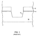
図1に示すように、半導体基板10の上面上にパッド酸化物11が形成され、一般的に1000Åを超える厚さでパッド酸化物11上に窒化ケイ素研磨停止層が形成される。
その後、図示しないフォトマスクを使用して、窒化物研磨停止層12、パッド酸化物11を貫通する開口部が形成され、トレンチ12が半導体基板10中に形成される。
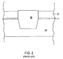
その後、窒化物研磨停止層12およびパッド酸化物層11を除去する。また、活性領域を形成する前に、クリーニングステップを実行する。
このようなクリーニングステップは、図3に示すようなディボット30を形成してしまう。
図4に示すように、浅いソース/ドレイン領域40上に形成されるシリサイド領域41は、参照符号42によって示すように、形成された結合深さより下に急峻に下方に成長してしまい、後の段階において高いリーク電流およびショートにつながってしまう。
STIフィールド端部におけるドーパント、特にホウ素の偏析は、接合深さを浅くする。
したがって、接合部をシリサイド化した後、シリサイド42は基板にまで達し、ソース/ドレイン接合部からウェルまたは基板までショートすることとなり、したがって大量のリーク電流が発生することとなる。
このキンクの存在は、設計された電気的特性を異なる特性にしてしまう。これによって、一定の特性を有するトランジスタの製造ができなくなる。
本発明の実施形態の一例はさらに、シャロートレンチ分離領域に隣接する半導体基板中に不純物領域を形成すべく、窒化物研磨停止層を貫通してイオンを注入し、絶縁材料の上面が半導体基板の上面と実質的に同一平面となるように、トレンチを充てんする絶縁材料の上面の一部を除去するエッチングを行い、窒化物研磨停止層を除去する。
その後、従来の技術を使用して、基板上にゲート酸化層が形成され、このゲート酸化層の上にゲート電極層が形成される。
したがって、図面および詳細な説明は、実質的に単なる例であり、これに制限されない。
図1ないし図4において、同じ構造は同じ参照符号によって示される。また、図5ないし図11において、同じ構造は同じ参照符号によって示される。
後続するステップにおいて、活性領域を形成するのにイオン注入が必要となり、厚い窒化膜はこのイオン注入を阻害してしまうので、このような厚い窒化物研磨停止層は一般的に、STI酸化物研磨の直後に除去される。
活性領域の形成には多くのマスキングステップ、注入ステップおよびクリーニングステップが使用され、STI領域の角部にディボットを形成してしまうことになる。
この問題に対する従来の手法は、例えば、後に実行される酸化物研磨クリーニングを最適化したり、STI酸化物を充てんする前の窒化物プルバックを最適化して、これらのディボットを最小化するようにしていた。
しかしながら、このようなアプローチでは、STIディボットの問題を十分に解決されていない。
窒化ケイ素の研磨エッチング停止層に適当な厚さは、例えば100Åのような50Åから150Åである。
より正確には、薄い窒化物エッチング停止層は、活性領域を形成するためのマスキング、イオン注入およびクリーニングステップを含んだ後の処理の間、除去されずに残される。
薄い窒化物エッチング停止層を使用すれば、充てんしたトレンチの角部を十分に保護できる。これによって、ディボットを形成することにつながるSTIの角部における酸化物の等方性エッチングされないようになる。
さらに、窒化物研磨停止層が薄いので、イオン注入は阻害されない。
実際、比較的窒化物層で覆われていない素のままの(bare)シリコンの表面がすぐに一律でない自然酸化膜を形成するのに対し、窒化物の表面はより安定しているので、薄い窒化物研磨停止層の使用は、注入において、より一律な表面を提供することができる。
したがって、本発明の実施形態によれば、窒化物研磨停止層は、ゲート酸化膜が形成されるまでそのまま除去されずに残され、これによって、活性シリコン領域を保護し、さらにより平坦な表面を形成し、そして実質的にディボットを避けるまたは減らす。
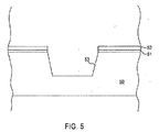
図5に示すように、例えば150Åのように、50Åから200Åの厚さのパッド酸化物を、半導体基板50の上面上に形成する。
本発明の実施形態にしたがって、パッド酸化物51上に非常に薄い窒化ケイ素エッチング停止層52を形成する。
窒化ケイ素エッチング停止層52は一般的に、例えば100Åのように、50Åから150Åの厚さで形成される。
その後、例えば従来のフォトリソグラフィ技術およびエッチング技術を使用することにより、トレンチ53を基板50中に形成する。
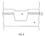
その後、図6に示すように、シリコン酸化物のような絶縁材料60をたい積して、トレンチを充てんし、また、例えばCVDによって窒化ケイ素研磨停止層52上に表土を形成する。
その後、例えばCMPによるプレーナ化を実行して、図7に示される中間構造を形成する。この図において、参照符号70はSTI酸化物フィルを示す。
一般的にCMPは、窒化ケイ素研磨停止層52上で停止する際に窒化ケイ素研磨停止層52の上面から20Åだけが除去されるように、実行される。
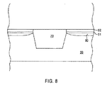
しかしながら、本発明の実施形態によれば、従来の方法で実行される後のマスキング、イオン注入、およびクリーニングステップの間、比較的薄い窒化ケイ素研磨停止層52が除去されず残され、図8に示すように、不純物領域80を形成されることになる。この不純物領域80は最終的に、トランジスタのソース/ドレイン領域に使用することができる。
窒化ケイ素研磨停止層52は比較的薄いので、注入の間にイオンがブロッキングされることは事実上ほとんどない。
さらに、窒化ケイ素層は、不純物領域の形成において、より均一性を高くすることができる安定した表面を形成する。
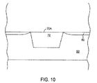
その後、例えばフッ化水素酸を使用して、窒化ケイ素研磨停止層52を除去する。また、それからパッド酸化物層51を除去し、図10に記載する構造となる。
その後の処理を実行して、半導体基板50上のゲート電極100(半導体基板50とゲート電極100との間にゲート酸化膜101が存在する)と、その上の絶縁側壁スペーサ102と、を含む、図11に示すようなトランジスタ構造を形成する。
図11における参照符号103は層間絶縁膜を示し、素子50は、基板50上の活性領域80まで絶縁層を貫通する電気コンタクトを示す。
本発明の実施形態は、戦略的に、窒化ケイ素研磨停止層の厚さを400Å以下に減少し、活性領域を形成する際、従来のクリーニングステップの間にトレンチの角部が等方性エッチングされないように保護すべく、CMPの直後に窒化ケイ素研磨停止層を除去せずに残し、イオン注入中に薄い窒化ケイ素研磨停止層を除去せずに残す。これにより、均一性の高い注入領域を形成する。
本発明は、特に、サブミクロンの寸法で半導体デバイスを製造する際に適用することができる。
Claims (7)
- 半導体基板(50)上に、400Å以下の厚さで、窒化物研磨停止層(52)を形成し、
前記窒化物研磨停止層中に開口部を形成すると共に、前記基板中にトレンチを形成し、
前記窒化物研磨停止層上に表土を形成する絶縁材料でトレンチを充てんし、
平坦な上面を形成すべく、前記窒化物研磨停止層上で停止するように研磨し、これにより、シャロートレンチ分離領域(70)を形成する、
半導体デバイスを製造する方法。 - 50Åから150Åの厚さで、前記窒化物研磨停止層(52)を形成する、請求項1記載の方法。
- 前記窒化物研磨停止層(52)の20Åのみを除去するとともに、前記平坦な上面を形成するように研磨する、請求項1記載の方法。
- 前記半導体基板(50)の上面上にパッド酸化物層(51)を形成し、
前記パッド酸化物層(51)上に前記窒化物研磨停止層(52)を形成する、請求項1記載の方法。 - さらに、前記シャロートレンチ分離領域(70)に隣接する前記半導体基板中に不純物領域(80)を形成するように、前記窒化物研磨停止層(52)を貫通してイオンを注入する、請求項1記載の方法。
- さらに、前記窒化物研磨停止層(52)を除去し、
前記窒化物研磨停止層(52)を除去した後、前記半導体基板上にゲート酸化層(101)を形成し、
前記ゲート酸化層(101)上にゲート電極(100)を形成する、請求項5記載の方法。 - さらに、前記窒化物研磨停止層(52)を除去する前に、前記絶縁材料の上面が前記半導体基板の上面と実質的に同一平面となるように、前記トレンチを充てんする前記絶縁材料の上面(70A)の一部を除去するエッチングを行う、請求項6記載の方法。
Applications Claiming Priority (2)
| Application Number | Priority Date | Filing Date | Title |
|---|---|---|---|
| US10/791,759 US7091106B2 (en) | 2004-03-04 | 2004-03-04 | Method of reducing STI divot formation during semiconductor device fabrication |
| PCT/US2005/006177 WO2005093825A1 (en) | 2004-03-04 | 2005-02-26 | Method of reducing sti divot formation during semiconductor device fabrication |
Publications (2)
| Publication Number | Publication Date |
|---|---|
| JP2007526652A true JP2007526652A (ja) | 2007-09-13 |
| JP2007526652A5 JP2007526652A5 (ja) | 2009-11-26 |
Family
ID=34911706
Family Applications (1)
| Application Number | Title | Priority Date | Filing Date |
|---|---|---|---|
| JP2007501861A Pending JP2007526652A (ja) | 2004-03-04 | 2005-02-26 | 半導体デバイス製造の間のstiディボット形成を減少する方法 |
Country Status (8)
| Country | Link |
|---|---|
| US (1) | US7091106B2 (ja) |
| JP (1) | JP2007526652A (ja) |
| KR (1) | KR20060129037A (ja) |
| CN (1) | CN1926679B (ja) |
| DE (1) | DE112005000512B4 (ja) |
| GB (1) | GB2426126B (ja) |
| TW (1) | TWI355678B (ja) |
| WO (1) | WO2005093825A1 (ja) |
Cited By (2)
| Publication number | Priority date | Publication date | Assignee | Title |
|---|---|---|---|---|
| US9960183B2 (en) | 2016-06-03 | 2018-05-01 | Renesas Electronics Corporation | Method of manufacturing semiconductor device |
| US10002885B2 (en) | 2016-09-16 | 2018-06-19 | Renesas Electronics Corporation | Manufacturing method of semiconductor device |
Families Citing this family (18)
| Publication number | Priority date | Publication date | Assignee | Title |
|---|---|---|---|---|
| KR100568259B1 (ko) * | 2004-12-14 | 2006-04-07 | 삼성전자주식회사 | 트렌치 소자 분리형 반도체 장치 및 그 형성 방법 |
| US20080204580A1 (en) * | 2007-02-28 | 2008-08-28 | Micron Technology, Inc. | Method, apparatus and system providing imaging device with color filter array |
| US20090053834A1 (en) * | 2007-08-23 | 2009-02-26 | Vladimir Alexeevich Ukraintsev | Use of scatterometry for in-line detection of poly-si strings left in sti divot after gate etch |
| KR100880227B1 (ko) * | 2007-10-09 | 2009-01-28 | 주식회사 동부하이텍 | 플래시 메모리 소자의 제조방법 |
| US7745320B2 (en) * | 2008-05-21 | 2010-06-29 | Chartered Semiconductor Manufacturing, Ltd. | Method for reducing silicide defects in integrated circuits |
| WO2010125428A1 (en) * | 2009-04-30 | 2010-11-04 | X-Fab Semiconductor Foundries Ag | Manufacturing integrated circuit components having multiple gate oxidations |
| US8274114B2 (en) * | 2010-01-14 | 2012-09-25 | Broadcom Corporation | Semiconductor device having a modified shallow trench isolation (STI) region and a modified well region |
| US8283722B2 (en) | 2010-06-14 | 2012-10-09 | Broadcom Corporation | Semiconductor device having an enhanced well region |
| US9123807B2 (en) | 2010-12-28 | 2015-09-01 | Broadcom Corporation | Reduction of parasitic capacitance in a semiconductor device |
| US20120292735A1 (en) | 2011-05-20 | 2012-11-22 | GLOBALFOUNDRIES Singapore Pte.Ltd. | Corner transistor suppression |
| US9263556B2 (en) * | 2012-06-29 | 2016-02-16 | Taiwan Semiconductor Manufacturing Company, Ltd. | Silicide process using OD spacers |
| US8716102B2 (en) * | 2012-08-14 | 2014-05-06 | Globalfoundries Inc. | Methods of forming isolation structures for semiconductor devices by performing a dry chemical removal process |
| US8603895B1 (en) | 2012-09-11 | 2013-12-10 | Globalfoundries Inc. | Methods of forming isolation structures for semiconductor devices by performing a deposition-etch-deposition sequence |
| US9219059B2 (en) | 2012-09-26 | 2015-12-22 | International Business Machines Corporation | Semiconductor structure with integrated passive structures |
| CN111341724B (zh) * | 2018-12-19 | 2022-11-04 | 上海新微技术研发中心有限公司 | 浅沟槽隔离工艺及浅沟槽隔离结构 |
| KR20200145974A (ko) * | 2019-06-21 | 2020-12-31 | 삼성전자주식회사 | 반도체 소자 및 그 제조 방법 |
| US12002707B2 (en) | 2020-08-06 | 2024-06-04 | Changxin Memory Technologies, Inc. | Semiconductor structure and manufacturing method thereof |
| CN113611604A (zh) * | 2021-03-19 | 2021-11-05 | 联芯集成电路制造(厦门)有限公司 | 半导体元件的制作方法 |
Citations (7)
| Publication number | Priority date | Publication date | Assignee | Title |
|---|---|---|---|---|
| JPH098135A (ja) * | 1995-06-26 | 1997-01-10 | Toshiba Corp | 半導体装置の製造方法 |
| JPH1145996A (ja) * | 1997-07-28 | 1999-02-16 | Nec Corp | 半導体装置及びその製造方法 |
| JPH11102960A (ja) * | 1997-09-29 | 1999-04-13 | Nec Corp | 半導体装置の製造方法 |
| JPH11274496A (ja) * | 1998-02-19 | 1999-10-08 | Internatl Business Mach Corp <Ibm> | 改良されたインプラントを有する電界効果トランジスタおよびその製造方法 |
| JPH11340315A (ja) * | 1998-05-22 | 1999-12-10 | Nec Corp | 半導体装置の製造方法 |
| JP2001185731A (ja) * | 1999-12-24 | 2001-07-06 | Toshiba Corp | 半導体装置及びその製造方法 |
| JP2002329866A (ja) * | 2001-03-29 | 2002-11-15 | Sharp Corp | デュアルダマシン法による銅ゲートおよびそのインタコネクト |
Family Cites Families (13)
| Publication number | Priority date | Publication date | Assignee | Title |
|---|---|---|---|---|
| US98661A (en) * | 1870-01-11 | Ikank l | ||
| US5177028A (en) | 1991-10-22 | 1993-01-05 | Micron Technology, Inc. | Trench isolation method having a double polysilicon gate formed on mesas |
| US5234535A (en) * | 1992-12-10 | 1993-08-10 | International Business Machines Corporation | Method of producing a thin silicon-on-insulator layer |
| US5665633A (en) * | 1995-04-06 | 1997-09-09 | Motorola, Inc. | Process for forming a semiconductor device having field isolation |
| US5616513A (en) * | 1995-06-01 | 1997-04-01 | International Business Machines Corporation | Shallow trench isolation with self aligned PSG layer |
| US6555476B1 (en) | 1997-12-23 | 2003-04-29 | Texas Instruments Incorporated | Silicon carbide as a stop layer in chemical mechanical polishing for isolation dielectric |
| US6599810B1 (en) * | 1998-11-05 | 2003-07-29 | Advanced Micro Devices, Inc. | Shallow trench isolation formation with ion implantation |
| US6248641B1 (en) * | 1999-02-05 | 2001-06-19 | United Microelectronics Corp. | Method of fabricating shallow trench isolation |
| KR100346842B1 (ko) * | 2000-12-01 | 2002-08-03 | 삼성전자 주식회사 | 얕은 트렌치 아이솔레이션 구조를 갖는 반도체 디바이스및 그 제조방법 |
| US6432797B1 (en) | 2001-01-25 | 2002-08-13 | Chartered Semiconductor Manufacturing Ltd. | Simplified method to reduce or eliminate STI oxide divots |
| US6673695B1 (en) | 2002-02-01 | 2004-01-06 | Chartered Semiconductor Manufacturing Ltd. | STI scheme to prevent fox recess during pre-CMP HF dip |
| JP4318892B2 (ja) * | 2002-05-30 | 2009-08-26 | 富士通マイクロエレクトロニクス株式会社 | 電子装置の設計方法および製造方法 |
| US6566215B1 (en) * | 2002-06-06 | 2003-05-20 | Chartered Semiconductor Manufacturing Ltd. | Method of fabricating short channel MOS transistors with source/drain extensions |
-
2004
- 2004-03-04 US US10/791,759 patent/US7091106B2/en not_active Expired - Lifetime
-
2005
- 2005-02-26 DE DE112005000512T patent/DE112005000512B4/de not_active Expired - Fee Related
- 2005-02-26 KR KR1020067017589A patent/KR20060129037A/ko not_active Application Discontinuation
- 2005-02-26 GB GB0617207A patent/GB2426126B/en not_active Expired - Fee Related
- 2005-02-26 WO PCT/US2005/006177 patent/WO2005093825A1/en active Application Filing
- 2005-02-26 CN CN2005800068145A patent/CN1926679B/zh not_active Expired - Fee Related
- 2005-02-26 JP JP2007501861A patent/JP2007526652A/ja active Pending
- 2005-03-02 TW TW094106204A patent/TWI355678B/zh not_active IP Right Cessation
Patent Citations (7)
| Publication number | Priority date | Publication date | Assignee | Title |
|---|---|---|---|---|
| JPH098135A (ja) * | 1995-06-26 | 1997-01-10 | Toshiba Corp | 半導体装置の製造方法 |
| JPH1145996A (ja) * | 1997-07-28 | 1999-02-16 | Nec Corp | 半導体装置及びその製造方法 |
| JPH11102960A (ja) * | 1997-09-29 | 1999-04-13 | Nec Corp | 半導体装置の製造方法 |
| JPH11274496A (ja) * | 1998-02-19 | 1999-10-08 | Internatl Business Mach Corp <Ibm> | 改良されたインプラントを有する電界効果トランジスタおよびその製造方法 |
| JPH11340315A (ja) * | 1998-05-22 | 1999-12-10 | Nec Corp | 半導体装置の製造方法 |
| JP2001185731A (ja) * | 1999-12-24 | 2001-07-06 | Toshiba Corp | 半導体装置及びその製造方法 |
| JP2002329866A (ja) * | 2001-03-29 | 2002-11-15 | Sharp Corp | デュアルダマシン法による銅ゲートおよびそのインタコネクト |
Cited By (4)
| Publication number | Priority date | Publication date | Assignee | Title |
|---|---|---|---|---|
| US9960183B2 (en) | 2016-06-03 | 2018-05-01 | Renesas Electronics Corporation | Method of manufacturing semiconductor device |
| US10297613B2 (en) | 2016-06-03 | 2019-05-21 | Renesas Electronics Corporation | Method of manufacturing semiconductor device |
| US10002885B2 (en) | 2016-09-16 | 2018-06-19 | Renesas Electronics Corporation | Manufacturing method of semiconductor device |
| US10559595B2 (en) | 2016-09-16 | 2020-02-11 | Renesas Electronics Corporation | Manufacturing method of semiconductor device |
Also Published As
| Publication number | Publication date |
|---|---|
| GB2426126A (en) | 2006-11-15 |
| GB0617207D0 (en) | 2006-10-11 |
| CN1926679A (zh) | 2007-03-07 |
| TW200535945A (en) | 2005-11-01 |
| US7091106B2 (en) | 2006-08-15 |
| WO2005093825A1 (en) | 2005-10-06 |
| GB2426126B (en) | 2008-07-23 |
| TWI355678B (en) | 2012-01-01 |
| US20050196928A1 (en) | 2005-09-08 |
| CN1926679B (zh) | 2010-10-06 |
| DE112005000512T5 (de) | 2007-01-11 |
| KR20060129037A (ko) | 2006-12-14 |
| DE112005000512B4 (de) | 2011-09-08 |
Similar Documents
| Publication | Publication Date | Title |
|---|---|---|
| JP2007526652A (ja) | 半導体デバイス製造の間のstiディボット形成を減少する方法 | |
| US6482718B2 (en) | Method of manufacturing semiconductor device | |
| US7611950B2 (en) | Method for forming shallow trench isolation in semiconductor device | |
| US7361571B2 (en) | Method for fabricating a trench isolation with spacers | |
| KR100307651B1 (ko) | 반도체장치의제조방법 | |
| US7704892B2 (en) | Semiconductor device having local interconnection layer and etch stopper pattern for preventing leakage of current | |
| US20080081433A1 (en) | Method for Forming a Shallow Trench Isolation Structure | |
| US6150237A (en) | Method of fabricating STI | |
| US6313011B1 (en) | Method for suppressing narrow width effects in CMOS technology | |
| US6221736B1 (en) | Fabrication method for a shallow trench isolation structure | |
| US6271147B1 (en) | Methods of forming trench isolation regions using spin-on material | |
| US20080057668A1 (en) | Method for fabricating semiconductor device | |
| US7022583B1 (en) | Method of forming a shallow trench isolation device to prevent kick effect | |
| US6344374B1 (en) | Method of fabricating insulators for isolating electronic devices | |
| US7666755B2 (en) | Method of forming device isolation film of semiconductor device | |
| US7223698B1 (en) | Method of forming a semiconductor arrangement with reduced field-to active step height | |
| KR100558032B1 (ko) | 반도체 소자의 트렌치 소자분리 방법 | |
| US7144785B2 (en) | Method of forming isolation trench with spacer formation | |
| KR20090063657A (ko) | 소자 분리막 형성 방법 | |
| KR100673100B1 (ko) | 반도체소자의 소자분리방법 | |
| KR100624329B1 (ko) | 반도체 소자의 소자 분리막 절연성 강화 방법 | |
| KR20030001179A (ko) | 반도체 소자의 소자 격리층 형성 방법 | |
| KR100567032B1 (ko) | 이온 주입법을 이용한 소자 분리 방법 | |
| KR100559540B1 (ko) | 반도체소자의 트렌치형 소자분리 방법 | |
| KR100668837B1 (ko) | 반도체 소자의 소자분리막 형성방법 |
Legal Events
| Date | Code | Title | Description |
|---|---|---|---|
| A621 | Written request for application examination |
Free format text: JAPANESE INTERMEDIATE CODE: A621 Effective date: 20080226 |
|
| A521 | Request for written amendment filed |
Free format text: JAPANESE INTERMEDIATE CODE: A523 Effective date: 20091005 |
|
| RD03 | Notification of appointment of power of attorney |
Free format text: JAPANESE INTERMEDIATE CODE: A7423 Effective date: 20100421 |
|
| RD05 | Notification of revocation of power of attorney |
Free format text: JAPANESE INTERMEDIATE CODE: A7425 Effective date: 20100902 |
|
| A02 | Decision of refusal |
Free format text: JAPANESE INTERMEDIATE CODE: A02 Effective date: 20111005 |
