JP2005297963A - 電子検出器用保持ポケット - Google Patents
電子検出器用保持ポケット Download PDFInfo
- Publication number
- JP2005297963A JP2005297963A JP2005117476A JP2005117476A JP2005297963A JP 2005297963 A JP2005297963 A JP 2005297963A JP 2005117476 A JP2005117476 A JP 2005117476A JP 2005117476 A JP2005117476 A JP 2005117476A JP 2005297963 A JP2005297963 A JP 2005297963A
- Authority
- JP
- Japan
- Prior art keywords
- tire
- layer
- cavity
- rubber
- lip
- Prior art date
- Legal status (The legal status is an assumption and is not a legal conclusion. Google has not performed a legal analysis and makes no representation as to the accuracy of the status listed.)
- Granted
Links
- 210000001503 joint Anatomy 0.000 claims abstract description 20
- 238000012544 monitoring process Methods 0.000 claims abstract description 12
- 239000010410 layer Substances 0.000 claims description 96
- 238000000034 method Methods 0.000 claims description 35
- 239000000463 material Substances 0.000 claims description 23
- 238000004519 manufacturing process Methods 0.000 claims description 13
- 239000011241 protective layer Substances 0.000 claims description 11
- 238000000465 moulding Methods 0.000 claims description 9
- 238000004073 vulcanization Methods 0.000 claims description 4
- 239000011324 bead Substances 0.000 claims description 3
- 239000002759 woven fabric Substances 0.000 claims description 3
- 230000000181 anti-adherent effect Effects 0.000 claims description 2
- 239000013013 elastic material Substances 0.000 claims description 2
- 238000012806 monitoring device Methods 0.000 claims description 2
- 239000004745 nonwoven fabric Substances 0.000 claims description 2
- 238000010586 diagram Methods 0.000 description 8
- 230000015572 biosynthetic process Effects 0.000 description 4
- 239000012528 membrane Substances 0.000 description 3
- 230000000694 effects Effects 0.000 description 2
- 230000001681 protective effect Effects 0.000 description 2
- VGGSQFUCUMXWEO-UHFFFAOYSA-N Ethene Chemical compound C=C VGGSQFUCUMXWEO-UHFFFAOYSA-N 0.000 description 1
- 239000005977 Ethylene Substances 0.000 description 1
- 239000004809 Teflon Substances 0.000 description 1
- 229920006362 Teflon® Polymers 0.000 description 1
- 230000005540 biological transmission Effects 0.000 description 1
- 230000015556 catabolic process Effects 0.000 description 1
- 239000011248 coating agent Substances 0.000 description 1
- 238000000576 coating method Methods 0.000 description 1
- 239000000470 constituent Substances 0.000 description 1
- 230000008878 coupling Effects 0.000 description 1
- 238000010168 coupling process Methods 0.000 description 1
- 238000005859 coupling reaction Methods 0.000 description 1
- 230000007547 defect Effects 0.000 description 1
- 238000006731 degradation reaction Methods 0.000 description 1
- 230000008021 deposition Effects 0.000 description 1
- 230000001939 inductive effect Effects 0.000 description 1
- 238000012423 maintenance Methods 0.000 description 1
- 230000013011 mating Effects 0.000 description 1
- 239000000203 mixture Substances 0.000 description 1
- 229920001296 polysiloxane Polymers 0.000 description 1
- 230000003014 reinforcing effect Effects 0.000 description 1
- 230000035939 shock Effects 0.000 description 1
- 239000002210 silicon-based material Substances 0.000 description 1
- 239000007921 spray Substances 0.000 description 1
- 230000007704 transition Effects 0.000 description 1
Images

Classifications
-
- B—PERFORMING OPERATIONS; TRANSPORTING
- B60—VEHICLES IN GENERAL
- B60C—VEHICLE TYRES; TYRE INFLATION; TYRE CHANGING; CONNECTING VALVES TO INFLATABLE ELASTIC BODIES IN GENERAL; DEVICES OR ARRANGEMENTS RELATED TO TYRES
- B60C23/00—Devices for measuring, signalling, controlling, or distributing tyre pressure or temperature, specially adapted for mounting on vehicles; Arrangement of tyre inflating devices on vehicles, e.g. of pumps or of tanks; Tyre cooling arrangements
- B60C23/02—Signalling devices actuated by tyre pressure
- B60C23/04—Signalling devices actuated by tyre pressure mounted on the wheel or tyre
- B60C23/0491—Constructional details of means for attaching the control device
- B60C23/0493—Constructional details of means for attaching the control device for attachment on the tyre
-
- B—PERFORMING OPERATIONS; TRANSPORTING
- B29—WORKING OF PLASTICS; WORKING OF SUBSTANCES IN A PLASTIC STATE IN GENERAL
- B29D—PRODUCING PARTICULAR ARTICLES FROM PLASTICS OR FROM SUBSTANCES IN A PLASTIC STATE
- B29D30/00—Producing pneumatic or solid tyres or parts thereof
- B29D30/06—Pneumatic tyres or parts thereof (e.g. produced by casting, moulding, compression moulding, injection moulding, centrifugal casting)
- B29D30/08—Building tyres
- B29D30/20—Building tyres by the flat-tyre method, i.e. building on cylindrical drums
-
- B—PERFORMING OPERATIONS; TRANSPORTING
- B29—WORKING OF PLASTICS; WORKING OF SUBSTANCES IN A PLASTIC STATE IN GENERAL
- B29D—PRODUCING PARTICULAR ARTICLES FROM PLASTICS OR FROM SUBSTANCES IN A PLASTIC STATE
- B29D30/00—Producing pneumatic or solid tyres or parts thereof
- B29D30/0061—Accessories, details or auxiliary operations not otherwise provided for
- B29D2030/0077—Directly attaching monitoring devices to tyres before or after vulcanization, e.g. microchips
Landscapes
- Engineering & Computer Science (AREA)
- Mechanical Engineering (AREA)
- Tyre Moulding (AREA)
- Tires In General (AREA)
- Measuring Fluid Pressure (AREA)
- Fluid-Damping Devices (AREA)
Abstract
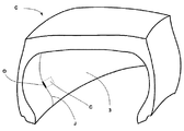
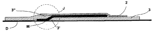
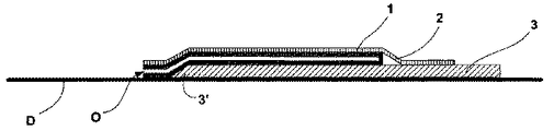
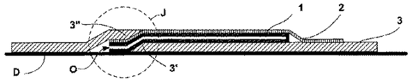
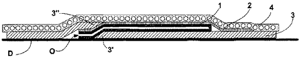
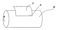
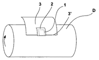
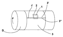
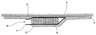
【解決手段】 着脱自在な電子監視モジュール(D)を受け入れるよう設計されたキャビティ(C)を有するタイヤ(P)であって、キャビティ(C)がタイヤ(P)の構成部品の内部に形成されているタイヤにおいて、キャビティ(C)の開口部(O)が、タイヤ(P)の内容積部内へ開口し、タイヤ(P)の内容積部に隣接したゴム異形要素の組立体により形成された第1の層(3)の突合せ継ぎ部(J)の一部上に位置していることを特徴とするタイヤ(P)。
【選択図】 図1
Description
タイヤをいったん車輪に装着すると、タイヤによって形成されたキャビティ内部に位置決めされた監視モジュールは、多種多様な支持体上に配置できる。かくして、監視モジュールは、車輪リングに固定され、タイヤの内壁に固定され又は結合され、或いはタイヤのコンポーネント内に一体化された弁に固定できる。これら解決策の中の1つの選択は、タイヤの性状及びタイヤにおける力、電子モジュールのエネルギ源の性状、監視される情報及び保守目的で望ましい接近性で決まる。
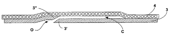
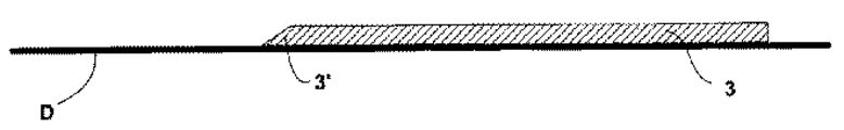
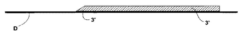
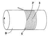
−タイヤ(P)の内容積部に隣接したゴム異形要素の組立体から成り、縁部が突合せ継ぎ部(J)の第1のリップ(3′)を有する第1の層(3)の区分の第1部分を成型ドラム(D)上に配置する工程と、
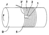
−粘着防止製品をキャビティ(C)を境界付けるようになった第1の層の領域上及びリップ(3′)の隣接部分上に局所的に付着させる工程と、
−第2のリップ(3″)を有する区分の第2区分を定位置に置くことにより第1の層の区分の位置決めを完了させる工程と、
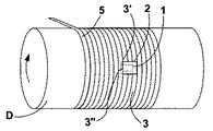
−突合せ継ぎ部(J)の第1のリップ(3′)と第2のリップ(3″)を互いに合わせる工程と、第1の層とのゴム結合部を形成するゴム異形要素の組立体から成る第2の層(4)を定位置に置く工程と、
−タイヤを形成するゴム異形要素の位置決めを続行して完了させる工程と、
−タイヤを硬化成型機で加硫する工程とから成る。
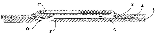
−タイヤ(P)の内容積部に隣接したゴム異形要素の組立体から成り、縁部が突合せ継ぎ部(J)の第1のリップ(3′)を有する第1の層(3)の区分の第1部分を成型ドラム(D)上に配置する工程と、
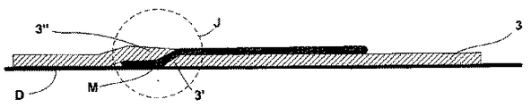
−フェースの両方が粘着防止材料で被覆された着脱自在な中間要素(M)をキャビティ(C)を境界付けるようになった区分の第1部分の領域上及び隣接のリップ(3′)上に位置決めする工程と、
−第2のリップ(3″)を有する区分の第2区分を定位置に置くことにより第1の層の区分の位置決めを完了させる工程と、
−第1のリップ(3′)と第2のリップ(3″)を中間パッチ(M)により被覆されている部分を除き、突合せ継ぎ部(J)の長さに沿って互いに合わせる工程と、
−第1の層とのゴム結合部を形成するゴム異形要素の組立体から成る第2の層(4)を定位置に置く工程と、
−タイヤを形成するゴム異形要素の位置決めを続行する工程と、
−タイヤを加硫する工程と、
−中間要素(M)を開口部(O)から抜き取る工程とから成る。
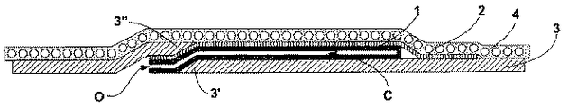
−タイヤ(P)の内容積部に隣接したゴム異形要素の組立体から成り、縁部が突合せ継ぎ部(J)の第1のリップ(3′)を有する第1の層(3)の区分の第1部分を成型ドラム(D)上に配置する工程と、
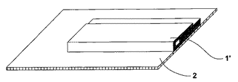
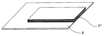
−延伸性材料の2つの層から成っていて、フェースの両方が粘着防止材料で被覆された中間要素(1,1′,1″)をキャビティ(C)を境界付けるようになった区分の第1部分の領域上及び隣接のリップ(3′)上に位置決めする工程と、
−第2のリップ(3″)を有する区分の第2区分を定位置に置くことにより第1の層の区分の位置決めを完了させる工程と、
−第1のリップ(3′)と第2のリップ(3″)を中間パッチ(M)により被覆されている部分を除き、突合せ継ぎ部(J)の長さに沿って互いに合わせる工程と、
−第1の層とのゴム結合部を形成するゴム異形要素の組立体から成る第2の層(4)を定位置に置く工程と、
−タイヤを形成するゴム異形要素の位置決めを続行する工程と、
−タイヤを加硫する工程とから成る。
2 裏当て層
3 第1の層
3′,3″ リップ
4 第2の層
C キャビティ
D 電子監視モジュール
J 突合せ継ぎ部
M 中間パッチ
O 開口部
P タイヤ
S 検出器
Claims (18)
- 着脱自在な電子監視モジュール(D)を受け入れるよう設計されたキャビティ(C)を有するタイヤ(P)であって、前記キャビティ(C)が前記タイヤ(P)の構成部品の内部に形成されているタイヤにおいて、キャビティ(C)の開口部(O)が、タイヤ(P)の内容積部内へ開口し、タイヤ(P)の内容積部に隣接したゴム異形要素の組立体により形成された第1の層(3)の突合せ継ぎ部(J)の一部上に位置していることを特徴とするタイヤ(P)。
- 前記キャビティは、前記第1の層(3)と、前記第1の層とのゴム結合部を有するゴム異形要素により形成された第2の層(4)との間に設けられていることを特徴とする請求項1記載のキャビティ(C)を有するタイヤ(P)。
- 前記キャビティは、前記第1の層(3)と前記第2の層(4)との間にゴム結合部が局所的に存在しないことにより形成されることを特徴とする請求項1記載のキャビティ(C)を有するタイヤ(P)。
- 前記第1の層(3)を形成するゴム材料は、気密性を備えていることを特徴とする請求項1〜3のうちいずれか一に記載のタイヤ(P)。
- 内側フェース及び外側フェースを備えた裏当て層(2)を有し、前記裏当て層(2)は、その内側フェース全体にわたり前記第2の層(4)とゴム結合部を形成し、その外側フェースの一部は、キャビティ(C)に隣接していることを特徴とする請求項1記載のタイヤ(P)。
- 裏当て層(2)は、前記第1の層(3)の材料と同一の性質のゴム材料から成ることを特徴とする請求項5記載のタイヤ(P)。
- 第1の層(3)を形成するゴム異形要素の突合せ継ぎ部(J)の向きは、本質的に半径方向であることを特徴とする請求項1〜6のうちいずれか一に記載のタイヤ(P)。
- 第1の層(3)を形成するゴム異形要素の突合せ継ぎ部(J)の向きは、本質的に円周方向であることを特徴とする請求項1〜6のうちいずれか一に記載のタイヤ(P)。
- 第1の層(3)を形成するゴム異形要素の突合せ継ぎ部(J)の角度の向きは、円周方向に対し、0゜〜90゜であることを特徴とする請求項1〜6のうちいずれか一に記載のタイヤ(P)。
- キャビティ(C)は、タイヤのビードヒールとその上部クラウンとの間に半径方向に配置されていることを特徴とする請求項1記載のタイヤ(P)。
- 電子監視デバイスに接触するようになった保持キャビティ(C)の壁は、延伸性材料から成る保護層(1,1′)によって被覆されていることを特徴とする請求項2〜10のうちいずれか一に記載のタイヤ(P)。
- 保護層(1,1′)を形成する延伸性材料は、織布ベース又は不織布ベースを有することを特徴とする請求項11記載のタイヤ(P)。
- 保護層(1,1′)を形成する延伸性材料は、ゴムの性質を持つ弾性材料から成ることを特徴とする請求項11記載のタイヤ(P)。
- タイヤ(P)の製造方法であって、
−タイヤ(P)の内容積部に隣接したゴム異形要素の組立体から成り、縁部が突合せ継ぎ部(J)の第1のリップ(3′)を有する第1の層(3)の区分の第1部分を成型ドラム(D)上に配置する工程と、
−粘着防止製品をキャビティ(C)を境界付けるようになった第1の層の領域上及びリップ(3′)の隣接部分上に局所的に付着させる工程と、
−第2のリップ(3″)を有する前記区分の第2区分を定位置に置くことにより前記第1の層の区分の位置決めを完了させる工程と、
−突合せ継ぎ部(J)の第1のリップ(3′)と第2のリップ(3″)を互いに合わせる工程と、前記第1の層とのゴム結合部を形成するゴム異形要素の組立体から成る第2の層(4)を定位置に置く工程と、
−タイヤを形成するゴム異形要素の位置決めを続行する工程と、
−タイヤを加硫する工程とから成ることを特徴とする方法。 - タイヤ(P)の製造方法であって、
−タイヤ(P)の内容積部に隣接したゴム異形要素の組立体から成り、縁部が突合せ継ぎ部(J)の第1のリップ(3′)を有する第1の層(3)の区分の第1部分を成型ドラム(D)上に配置する工程と、
−フェースのうちの少なくとも1つが粘着防止材料で被覆された中間要素(1,1′,1″,M)をキャビティ(C)を境界付けるようになった区分の第1部分の領域上及び隣接のリップ(3′)上に位置決めする工程と、
−第2のリップ(3″)を有する前記区分の第2区分を定位置に置くことにより前記第1の層の区分の位置決めを完了させる工程と、
−第1のリップ(3′)と第2のリップ(3″)を互いに合わせる工程と、
−前記第1の層とのゴム結合部を形成するゴム異形要素の組立体から成る第2の層(4)を定位置に置く工程と、
−タイヤを形成するゴム異形要素の位置決めを続行する工程と、
−タイヤを加硫する工程とから成ることを特徴とする方法。 - 中間要素(M)の両方のフェースが粘着防止材料で被覆され、前記中間要素(M)は、加硫工程後、開口部(O)を通ってキャビティ(C)から抜き取られるようになっていることを特徴とする請求項15記載の方法。
- 第2の層(4)を位置決めする工程の実施前に、裏当て層(2)をキャビティ(C)を境界付けるようになった第1の層の領域上又は前記中間要素(1,1′,1″,M)上に位置決めする工程を実施することを特徴とする請求項14又は15記載の方法。
- 中間要素(1,1′,1″)は、保護層として役立つようタイヤ内に永続的にとどまるようになっており、前記中間要素は、それ自体折り返された延伸性材料から成り、その互いに接触しているフェースは、粘着防止製品で被覆されていることを特徴とする請求項15記載の方法。
Applications Claiming Priority (2)
| Application Number | Priority Date | Filing Date | Title |
|---|---|---|---|
| FR0402886A FR2867721A1 (fr) | 2004-03-18 | 2004-03-18 | Poche de maintien de detecteur electronique |
| FR0402886 | 2004-03-18 |
Publications (3)
| Publication Number | Publication Date |
|---|---|
| JP2005297963A true JP2005297963A (ja) | 2005-10-27 |
| JP2005297963A5 JP2005297963A5 (ja) | 2008-04-24 |
| JP4884692B2 JP4884692B2 (ja) | 2012-02-29 |
Family
ID=34896666
Family Applications (1)
| Application Number | Title | Priority Date | Filing Date |
|---|---|---|---|
| JP2005117476A Expired - Fee Related JP4884692B2 (ja) | 2004-03-18 | 2005-03-18 | 電子検出器用保持ポケット |
Country Status (8)
| Country | Link |
|---|---|
| US (1) | US7556074B2 (ja) |
| EP (1) | EP1586468B1 (ja) |
| JP (1) | JP4884692B2 (ja) |
| CN (1) | CN100560388C (ja) |
| AT (1) | ATE510709T1 (ja) |
| AU (1) | AU2005201161A1 (ja) |
| BR (1) | BRPI0500897B1 (ja) |
| FR (1) | FR2867721A1 (ja) |
Cited By (3)
| Publication number | Priority date | Publication date | Assignee | Title |
|---|---|---|---|---|
| WO2007114204A1 (ja) * | 2006-03-29 | 2007-10-11 | The Yokohama Rubber Co., Ltd. | 空気入りタイヤの製造方法 |
| JP2013508209A (ja) * | 2009-10-21 | 2013-03-07 | レマ ティプ トップ ゲーエムベーハー | エラストマー部材へ保持器を取り付けるための締結システム |
| JP2018501366A (ja) * | 2014-12-19 | 2018-01-18 | コンパニー ゼネラール デ エタブリッスマン ミシュラン | 表面上に要素を受け取る準備ができているタイヤ |
Families Citing this family (20)
| Publication number | Priority date | Publication date | Assignee | Title |
|---|---|---|---|---|
| DE10243441B4 (de) * | 2002-09-18 | 2004-12-30 | Continental Aktiengesellschaft | Transponder für Reifen |
| US7770444B2 (en) * | 2005-12-13 | 2010-08-10 | Michelin Recherche Et Technique S.A. | Patch for fixing an electronic system to a tire |
| FR2902173B1 (fr) | 2006-06-09 | 2008-12-05 | Michelin Soc Tech | Valve de pneumatique et procede pour son demontage |
| EP2162718B1 (en) * | 2007-05-25 | 2011-08-03 | Société de Technologie MICHELIN | Method to protect tire electronics |
| FR2934967B1 (fr) * | 2008-08-14 | 2010-08-13 | Michelin Soc Tech | Pneumatique sans chambre a air ayant une gomme interieure fendue, et procede pour sa fabrication |
| FR2937284B1 (fr) * | 2008-10-20 | 2010-11-19 | Michelin Soc Tech | Organe pour pneumatique et pneumatique instrumente |
| US8281827B2 (en) * | 2008-11-06 | 2012-10-09 | The Yokohama Rubber Co., Ltd. | Pneumatic tire |
| FR2981010B1 (fr) * | 2011-10-05 | 2014-06-13 | Michelin Soc Tech | Kit et procede pour la fixation temporaire d'un dispositif electronique sur un support d'une enveloppe pneumatique |
| US20130133800A1 (en) * | 2011-11-29 | 2013-05-30 | Jean-Claude Patrice Philippe Griffoin | System for attaching an electronic device or other item to a pneumatic tire |
| KR101775797B1 (ko) * | 2015-11-30 | 2017-09-06 | 한국타이어 주식회사 | 흡음재 고정밴드를 구비하는 타이어 흡음재고정구조 및 이의 포함하여 제조되는 타이어 |
| FR3063041B1 (fr) * | 2017-02-17 | 2019-05-03 | Compagnie Generale Des Etablissements Michelin | Dispositif de fixation a une enveloppe pneumatique d'un organe electronique. |
| JP6756004B1 (ja) * | 2019-05-08 | 2020-09-16 | Toyo Tire株式会社 | タイヤおよびタイヤの製造方法 |
| JP6756021B1 (ja) * | 2019-08-23 | 2020-09-16 | Toyo Tire株式会社 | タイヤおよびタイヤの製造方法 |
| DE102019215069A1 (de) * | 2019-09-30 | 2021-04-01 | Continental Reifen Deutschland Gmbh | Reifen |
| IT202200015150A1 (it) * | 2022-07-19 | 2024-01-19 | Bridgestone Europe Nv Sa | Pneumatico provvisto di un dispositivo elettronico |
| JP7323023B1 (ja) * | 2022-08-03 | 2023-08-08 | 住友ゴム工業株式会社 | タイヤ |
| CN116001339A (zh) * | 2022-10-09 | 2023-04-25 | 厦门正新海燕轮胎有限公司 | 在轮胎的内表面形成可容装电子装置的袋型容器的方法 |
| IT202300023487A1 (it) | 2023-11-08 | 2025-05-08 | Bridgestone Europe Nv Sa | Pneumatico provvisto di un dispositivo elettronico |
| IT202300023481A1 (it) | 2023-11-08 | 2025-05-08 | Bridgestone Europe Nv Sa | Pneumatico provvisto di un dispositivo elettronico |
| IT202300023475A1 (it) * | 2023-11-08 | 2025-05-08 | Bridgestone Europe Nv Sa | Pneumatico provvisto di un dispositivo elettronico e corrispondente metodo di produzione |
Citations (12)
| Publication number | Priority date | Publication date | Assignee | Title |
|---|---|---|---|---|
| JPH0713505U (ja) * | 1993-08-18 | 1995-03-07 | 株式会社ブリヂストン | 空気入りタイヤ |
| JPH0867117A (ja) * | 1994-06-03 | 1996-03-12 | Bridgestone Corp | 車両用タイヤの状態の監視方法及び監視用デバイス内蔵のタイヤ |
| JPH11216781A (ja) * | 1997-11-28 | 1999-08-10 | Sumitomo Rubber Ind Ltd | 空気入りタイヤおよび空気入りタイヤの製造方法 |
| JPH11278021A (ja) * | 1998-02-10 | 1999-10-12 | Bridgestone Corp | 監視装置を有するタイヤ |
| JP2000168321A (ja) * | 1998-12-04 | 2000-06-20 | Bridgestone Corp | 電子式モニタ―装置の接合用に空気タイヤを調製するための方法 |
| JP2001063325A (ja) * | 1999-08-27 | 2001-03-13 | Yokohama Rubber Co Ltd:The | トランスポンダを埋め込んだ空気入りタイヤ及びその製造方法 |
| JP2002214060A (ja) * | 2001-01-12 | 2002-07-31 | Yokohama Rubber Co Ltd:The | タイヤ装着用トランスポンダ及びトランスポンダ装着タイヤ並びにその製造方法 |
| JP2002541003A (ja) * | 1999-11-24 | 2002-12-03 | ミシュラン ルシェルシェ エ テクニク ソシエテ アノニム | モニター付き自動車タイヤと、モニターの保持組立体 |
| EP1318032A2 (de) * | 2001-12-05 | 2003-06-11 | Continental Aktiengesellschaft | Verfahren zur Herstellung eines Fahrzeugreifens mit einer Transpondereinheit |
| WO2003070496A1 (en) * | 2002-02-18 | 2003-08-28 | Bridgestone/Firestone North American Tire, Llc | Attachment method for tire tag |
| JP2003525804A (ja) * | 2000-03-09 | 2003-09-02 | ブリヂストン/フアイヤーストーン・ノース・アメリカン・タイヤ・エルエルシー | タイヤモニターに給電する方法と装置 |
| WO2003095243A1 (en) * | 2002-05-07 | 2003-11-20 | Bridgestone/Firestone North American Tire, Llc | Monitoring device and patch assembly |
Family Cites Families (5)
| Publication number | Priority date | Publication date | Assignee | Title |
|---|---|---|---|---|
| GB1434732A (en) * | 1972-05-23 | 1976-05-05 | Dunlop Ltd | Pneumatic tyres and methods of manufacture thereof |
| DE69406224T2 (de) * | 1993-08-18 | 1998-03-19 | Bridgestone Corp | Luftreifen mit einem Transponder, Einrichtung und Verfahren zum Aufnehmen und Ablesen von einem Transponder |
| DE10209580B4 (de) * | 2002-03-05 | 2014-01-30 | Goodyear Dunlop Tires Germany Gmbh | Fahrzeugreifen mit integriertem Transponder |
| DE10243441B4 (de) * | 2002-09-18 | 2004-12-30 | Continental Aktiengesellschaft | Transponder für Reifen |
| US6978669B2 (en) * | 2003-12-22 | 2005-12-27 | The Goodyear Tire & Rubber Company | Method and assembly of sensor ready tires |
-
2004
- 2004-03-18 FR FR0402886A patent/FR2867721A1/fr active Pending
-
2005
- 2005-03-16 EP EP05102052A patent/EP1586468B1/fr not_active Expired - Lifetime
- 2005-03-16 AT AT05102052T patent/ATE510709T1/de not_active IP Right Cessation
- 2005-03-17 AU AU2005201161A patent/AU2005201161A1/en not_active Abandoned
- 2005-03-17 BR BRPI0500897-2A patent/BRPI0500897B1/pt not_active IP Right Cessation
- 2005-03-17 CN CNB2005100554357A patent/CN100560388C/zh not_active Expired - Fee Related
- 2005-03-18 US US11/083,215 patent/US7556074B2/en not_active Expired - Fee Related
- 2005-03-18 JP JP2005117476A patent/JP4884692B2/ja not_active Expired - Fee Related
Patent Citations (12)
| Publication number | Priority date | Publication date | Assignee | Title |
|---|---|---|---|---|
| JPH0713505U (ja) * | 1993-08-18 | 1995-03-07 | 株式会社ブリヂストン | 空気入りタイヤ |
| JPH0867117A (ja) * | 1994-06-03 | 1996-03-12 | Bridgestone Corp | 車両用タイヤの状態の監視方法及び監視用デバイス内蔵のタイヤ |
| JPH11216781A (ja) * | 1997-11-28 | 1999-08-10 | Sumitomo Rubber Ind Ltd | 空気入りタイヤおよび空気入りタイヤの製造方法 |
| JPH11278021A (ja) * | 1998-02-10 | 1999-10-12 | Bridgestone Corp | 監視装置を有するタイヤ |
| JP2000168321A (ja) * | 1998-12-04 | 2000-06-20 | Bridgestone Corp | 電子式モニタ―装置の接合用に空気タイヤを調製するための方法 |
| JP2001063325A (ja) * | 1999-08-27 | 2001-03-13 | Yokohama Rubber Co Ltd:The | トランスポンダを埋め込んだ空気入りタイヤ及びその製造方法 |
| JP2002541003A (ja) * | 1999-11-24 | 2002-12-03 | ミシュラン ルシェルシェ エ テクニク ソシエテ アノニム | モニター付き自動車タイヤと、モニターの保持組立体 |
| JP2003525804A (ja) * | 2000-03-09 | 2003-09-02 | ブリヂストン/フアイヤーストーン・ノース・アメリカン・タイヤ・エルエルシー | タイヤモニターに給電する方法と装置 |
| JP2002214060A (ja) * | 2001-01-12 | 2002-07-31 | Yokohama Rubber Co Ltd:The | タイヤ装着用トランスポンダ及びトランスポンダ装着タイヤ並びにその製造方法 |
| EP1318032A2 (de) * | 2001-12-05 | 2003-06-11 | Continental Aktiengesellschaft | Verfahren zur Herstellung eines Fahrzeugreifens mit einer Transpondereinheit |
| WO2003070496A1 (en) * | 2002-02-18 | 2003-08-28 | Bridgestone/Firestone North American Tire, Llc | Attachment method for tire tag |
| WO2003095243A1 (en) * | 2002-05-07 | 2003-11-20 | Bridgestone/Firestone North American Tire, Llc | Monitoring device and patch assembly |
Cited By (4)
| Publication number | Priority date | Publication date | Assignee | Title |
|---|---|---|---|---|
| WO2007114204A1 (ja) * | 2006-03-29 | 2007-10-11 | The Yokohama Rubber Co., Ltd. | 空気入りタイヤの製造方法 |
| US8900389B2 (en) | 2006-03-29 | 2014-12-02 | The Yokohama Rubber Co., Ltd. | Method for producing pneumatic tire |
| JP2013508209A (ja) * | 2009-10-21 | 2013-03-07 | レマ ティプ トップ ゲーエムベーハー | エラストマー部材へ保持器を取り付けるための締結システム |
| JP2018501366A (ja) * | 2014-12-19 | 2018-01-18 | コンパニー ゼネラール デ エタブリッスマン ミシュラン | 表面上に要素を受け取る準備ができているタイヤ |
Also Published As
| Publication number | Publication date |
|---|---|
| FR2867721A1 (fr) | 2005-09-23 |
| AU2005201161A1 (en) | 2005-10-06 |
| EP1586468A3 (fr) | 2010-03-17 |
| JP4884692B2 (ja) | 2012-02-29 |
| US20050217774A1 (en) | 2005-10-06 |
| EP1586468A2 (fr) | 2005-10-19 |
| US7556074B2 (en) | 2009-07-07 |
| BRPI0500897A (pt) | 2005-11-01 |
| CN100560388C (zh) | 2009-11-18 |
| CN1669836A (zh) | 2005-09-21 |
| BRPI0500897B1 (pt) | 2014-12-02 |
| ATE510709T1 (de) | 2011-06-15 |
| EP1586468B1 (fr) | 2011-05-25 |
Similar Documents
| Publication | Publication Date | Title |
|---|---|---|
| JP4884692B2 (ja) | 電子検出器用保持ポケット | |
| KR20000047777A (ko) | 전자 모니터 장치의 신속한 접착을 위한 공기 타이어의내부라이너를 제조하는 방법 | |
| US6786990B1 (en) | Method of manufacturing sealant-containing tires, and sealant-containing tire | |
| JP2010514525A (ja) | 呼吸マスク用の膨張可能な顔面シールおよびその製造方法 | |
| JPH10129380A (ja) | 側部用エアバッグの製造方法 | |
| AU2012251774A1 (en) | Tyre | |
| JP3567431B2 (ja) | チューブレスタイヤ及びその製造方法 | |
| JPH0785915B2 (ja) | タイヤ成形機用内側ブラダーの製造方法および内側ブラダー | |
| JP2010158785A (ja) | タイヤの製造方法 | |
| EP0458436A2 (en) | Method for manufacturing curing envelope for use in tire retreading | |
| JP6728947B2 (ja) | ゴムテープ、ゴムテープ複合体及びその製造方法 | |
| JPH1034751A (ja) | 大型ゴム製品の継ぎ加硫方法 | |
| JP2011224907A (ja) | 空気入りタイヤの製造方法 | |
| JP2007050538A (ja) | 補強層の製造方法、空気のうの製造方法、及び成型ドラム | |
| JP6185762B2 (ja) | プレキュアトレッド、プレキュアトレッドの製造方法及びタイヤの製造方法 | |
| JP2007160844A (ja) | 円環状中空体の製造方法 | |
| WO2019124148A1 (ja) | タイヤ、及び、多孔質体の固定方法 | |
| CN109109573A (zh) | 一种具有钢丝圈/胎体编织骨架材料的橡胶轮胎结构及其制造方法 | |
| JP2007160833A (ja) | 円環状中空体の製造方法 | |
| JP2007130798A (ja) | 円環状中空体の製造方法 | |
| RU2452524C2 (ru) | Надувной лицевой обтюратор для респираторной маски и способ изготовления такого обтюратора | |
| JPH08107815A (ja) | 気嚢体及びその製造方法 | |
| KR101414436B1 (ko) | 타이어 제조방법 및 타이어 제조장치 | |
| JP2007050537A (ja) | 補強層の製造方法及び空気のうの製造方法 | |
| KR101414339B1 (ko) | 타이어 제조방법 및 타이어 제조장치 |
Legal Events
| Date | Code | Title | Description |
|---|---|---|---|
| A521 | Request for written amendment filed |
Free format text: JAPANESE INTERMEDIATE CODE: A523 Effective date: 20080307 |
|
| A621 | Written request for application examination |
Free format text: JAPANESE INTERMEDIATE CODE: A621 Effective date: 20080307 |
|
| A977 | Report on retrieval |
Free format text: JAPANESE INTERMEDIATE CODE: A971007 Effective date: 20101220 |
|
| A131 | Notification of reasons for refusal |
Free format text: JAPANESE INTERMEDIATE CODE: A131 Effective date: 20101227 |
|
| A521 | Request for written amendment filed |
Free format text: JAPANESE INTERMEDIATE CODE: A523 Effective date: 20110328 |
|
| TRDD | Decision of grant or rejection written | ||
| A01 | Written decision to grant a patent or to grant a registration (utility model) |
Free format text: JAPANESE INTERMEDIATE CODE: A01 Effective date: 20111107 |
|
| A01 | Written decision to grant a patent or to grant a registration (utility model) |
Free format text: JAPANESE INTERMEDIATE CODE: A01 |
|
| A61 | First payment of annual fees (during grant procedure) |
Free format text: JAPANESE INTERMEDIATE CODE: A61 Effective date: 20111207 |
|
| FPAY | Renewal fee payment (event date is renewal date of database) |
Free format text: PAYMENT UNTIL: 20141216 Year of fee payment: 3 |
|
| R150 | Certificate of patent or registration of utility model |
Ref document number: 4884692 Country of ref document: JP Free format text: JAPANESE INTERMEDIATE CODE: R150 Free format text: JAPANESE INTERMEDIATE CODE: R150 |
|
| R250 | Receipt of annual fees |
Free format text: JAPANESE INTERMEDIATE CODE: R250 |
|
| R250 | Receipt of annual fees |
Free format text: JAPANESE INTERMEDIATE CODE: R250 |
|
| R250 | Receipt of annual fees |
Free format text: JAPANESE INTERMEDIATE CODE: R250 |
|
| R250 | Receipt of annual fees |
Free format text: JAPANESE INTERMEDIATE CODE: R250 |
|
| LAPS | Cancellation because of no payment of annual fees |