JP2005297963A - Holding pocket for electronic detector - Google Patents
Holding pocket for electronic detector Download PDFInfo
- Publication number
- JP2005297963A JP2005297963A JP2005117476A JP2005117476A JP2005297963A JP 2005297963 A JP2005297963 A JP 2005297963A JP 2005117476 A JP2005117476 A JP 2005117476A JP 2005117476 A JP2005117476 A JP 2005117476A JP 2005297963 A JP2005297963 A JP 2005297963A
- Authority
- JP
- Japan
- Prior art keywords
- tire
- layer
- cavity
- rubber
- lip
- Prior art date
- Legal status (The legal status is an assumption and is not a legal conclusion. Google has not performed a legal analysis and makes no representation as to the accuracy of the status listed.)
- Granted
Links
- 238000012544 monitoring process Methods 0.000 claims abstract description 12
- 239000010410 layer Substances 0.000 claims description 96
- 238000000034 method Methods 0.000 claims description 35
- 239000000463 material Substances 0.000 claims description 23
- 210000001503 joint Anatomy 0.000 claims description 19
- 238000004519 manufacturing process Methods 0.000 claims description 13
- 239000011241 protective layer Substances 0.000 claims description 11
- 238000000465 moulding Methods 0.000 claims description 9
- 238000004073 vulcanization Methods 0.000 claims description 4
- 239000011324 bead Substances 0.000 claims description 3
- 239000002759 woven fabric Substances 0.000 claims description 3
- 230000000181 anti-adherent effect Effects 0.000 claims description 2
- 239000013013 elastic material Substances 0.000 claims description 2
- 238000012806 monitoring device Methods 0.000 claims description 2
- 239000004745 nonwoven fabric Substances 0.000 claims description 2
- 238000010586 diagram Methods 0.000 description 8
- 230000015572 biosynthetic process Effects 0.000 description 4
- 239000012528 membrane Substances 0.000 description 3
- 230000000694 effects Effects 0.000 description 2
- 230000001681 protective effect Effects 0.000 description 2
- VGGSQFUCUMXWEO-UHFFFAOYSA-N Ethene Chemical compound C=C VGGSQFUCUMXWEO-UHFFFAOYSA-N 0.000 description 1
- 239000005977 Ethylene Substances 0.000 description 1
- 239000004809 Teflon Substances 0.000 description 1
- 229920006362 Teflon® Polymers 0.000 description 1
- 230000005540 biological transmission Effects 0.000 description 1
- 230000015556 catabolic process Effects 0.000 description 1
- 239000011248 coating agent Substances 0.000 description 1
- 238000000576 coating method Methods 0.000 description 1
- 239000000470 constituent Substances 0.000 description 1
- 230000008878 coupling Effects 0.000 description 1
- 238000010168 coupling process Methods 0.000 description 1
- 238000005859 coupling reaction Methods 0.000 description 1
- 230000007547 defect Effects 0.000 description 1
- 238000006731 degradation reaction Methods 0.000 description 1
- 230000008021 deposition Effects 0.000 description 1
- 230000001939 inductive effect Effects 0.000 description 1
- 238000012423 maintenance Methods 0.000 description 1
- 230000013011 mating Effects 0.000 description 1
- 239000000203 mixture Substances 0.000 description 1
- 229920001296 polysiloxane Polymers 0.000 description 1
- 230000003014 reinforcing effect Effects 0.000 description 1
- 230000035939 shock Effects 0.000 description 1
- 239000002210 silicon-based material Substances 0.000 description 1
- 239000007921 spray Substances 0.000 description 1
- 230000007704 transition Effects 0.000 description 1
Images

Classifications
-
- B—PERFORMING OPERATIONS; TRANSPORTING
- B60—VEHICLES IN GENERAL
- B60C—VEHICLE TYRES; TYRE INFLATION; TYRE CHANGING; CONNECTING VALVES TO INFLATABLE ELASTIC BODIES IN GENERAL; DEVICES OR ARRANGEMENTS RELATED TO TYRES
- B60C23/00—Devices for measuring, signalling, controlling, or distributing tyre pressure or temperature, specially adapted for mounting on vehicles; Arrangement of tyre inflating devices on vehicles, e.g. of pumps or of tanks; Tyre cooling arrangements
- B60C23/02—Signalling devices actuated by tyre pressure
- B60C23/04—Signalling devices actuated by tyre pressure mounted on the wheel or tyre
- B60C23/0491—Constructional details of means for attaching the control device
- B60C23/0493—Constructional details of means for attaching the control device for attachment on the tyre
-
- B—PERFORMING OPERATIONS; TRANSPORTING
- B29—WORKING OF PLASTICS; WORKING OF SUBSTANCES IN A PLASTIC STATE IN GENERAL
- B29D—PRODUCING PARTICULAR ARTICLES FROM PLASTICS OR FROM SUBSTANCES IN A PLASTIC STATE
- B29D30/00—Producing pneumatic or solid tyres or parts thereof
- B29D30/06—Pneumatic tyres or parts thereof (e.g. produced by casting, moulding, compression moulding, injection moulding, centrifugal casting)
- B29D30/08—Building tyres
- B29D30/20—Building tyres by the flat-tyre method, i.e. building on cylindrical drums
-
- B—PERFORMING OPERATIONS; TRANSPORTING
- B29—WORKING OF PLASTICS; WORKING OF SUBSTANCES IN A PLASTIC STATE IN GENERAL
- B29D—PRODUCING PARTICULAR ARTICLES FROM PLASTICS OR FROM SUBSTANCES IN A PLASTIC STATE
- B29D30/00—Producing pneumatic or solid tyres or parts thereof
- B29D30/0061—Accessories, details or auxiliary operations not otherwise provided for
- B29D2030/0077—Directly attaching monitoring devices to tyres before or after vulcanization, e.g. microchips
Landscapes
- Engineering & Computer Science (AREA)
- Mechanical Engineering (AREA)
- Tyre Moulding (AREA)
- Tires In General (AREA)
- Measuring Fluid Pressure (AREA)
- Fluid-Damping Devices (AREA)
Abstract
Description
本発明は、一般に電子素子から成る監視モジュールをタイヤの内面上に着脱自在に保持することができる装置に関する。 The present invention generally relates to an apparatus capable of detachably holding a monitoring module comprising an electronic element on an inner surface of a tire.
タイヤに電子モジュールを用いることにより、製造又は人員、機材等の配備を監視する目的でデータを収集し、蓄積し、そして伝送し、より一般的に、ユーザにタイヤの寿命全体を通じてタイヤの性能の変遷について知らせることから成る多くの用途が実行可能になる。 By using electronic modules in tires, data is collected, stored, and transmitted for the purpose of monitoring manufacturing or deployment of personnel, equipment, etc. Many applications consisting of informing about the transition become feasible.
電子監視モジュールは、独立した電気エネルギ供給システム、例えばバッテリー又は誘導結合システムに接続された能動コンポーネントを有し、その目的は、本発明の要部をなさない。監視モジュールは、所望の情報を外部モジュールと交換するよう設計されており、外部モジュールは、高周波を介してユーザインタフェースとして働き、その周波数及び電力は、特定の伝送プロトコルによって定められる。モジュールは一般に、電子コンポーネントを衝撃並びにタイヤの内部雰囲気及びその周囲環境に関連した過酷さから保護するようになった可撓性又は剛性保護カバーの内部に配置される。
タイヤをいったん車輪に装着すると、タイヤによって形成されたキャビティ内部に位置決めされた監視モジュールは、多種多様な支持体上に配置できる。かくして、監視モジュールは、車輪リングに固定され、タイヤの内壁に固定され又は結合され、或いはタイヤのコンポーネント内に一体化された弁に固定できる。これら解決策の中の1つの選択は、タイヤの性状及びタイヤにおける力、電子モジュールのエネルギ源の性状、監視される情報及び保守目的で望ましい接近性で決まる。
The electronic monitoring module has active components connected to an independent electrical energy supply system, such as a battery or inductive coupling system, the purpose of which does not form part of the present invention. The monitoring module is designed to exchange desired information with an external module, which acts as a user interface via high frequencies, whose frequency and power are defined by a specific transmission protocol. The module is typically placed inside a flexible or rigid protective cover that is adapted to protect the electronic components from shock and the harshness associated with the tire's internal atmosphere and surrounding environment.
Once the tire is mounted on the wheel, the monitoring module positioned within the cavity formed by the tire can be placed on a wide variety of supports. Thus, the monitoring module can be fixed to the wheel ring, fixed to the inner wall of the tire, or connected to the valve integrated into the tire component. One of these solutions depends on the nature of the tire and the force on the tire, the nature of the energy source of the electronic module, the information being monitored and the accessibility desired for maintenance purposes.
弾性ポケットをタイヤの内壁に設ける解決策が、例えば米国特許第5,500,065号明細書に記載されている。しかしながら、かかる解決策は、タイヤを製造した後に位置決めされる必要があるという欠点を有している。これは、例えば米国特許第6,244,104号明細書に記載されているように、支持体又は弾性キャビティを受け入れる表面の部分を準備し、次に支持体を表面の上記一部上に結合し又は加硫することから成る特別な方法を実施することを必然的に伴う。 A solution for providing elastic pockets on the inner wall of the tire is described, for example, in US Pat. No. 5,500,065. However, such a solution has the disadvantage that it needs to be positioned after the tire has been manufactured. This prepares a portion of the surface that receives the support or elastic cavity, as described, for example, in US Pat. No. 6,244,104, and then couples the support onto the portion of the surface. Or necessarily carry out a special process consisting of vulcanizing.
本発明の目的は、監視モジュールを受け入れるよう設計されたキャビティを有するタイヤを提案することにより状況を改善することにあり、その製造方法は、公知の方法と比較して顕著な利点を奏する。 The object of the present invention is to remedy the situation by proposing a tire with a cavity designed to receive a monitoring module, and its manufacturing method offers significant advantages compared to known methods.
上記キャビティは、上記タイヤのコンポーネント内に配置され、本発明のタイヤは、キャビティの開口部が、タイヤの内容積部内へ開口し、タイヤの内容積部に隣接したゴム異形要素の組立体により形成された第1の層の突合せ継ぎ部の一部上に位置していることを特徴とする。タイヤの内容積部は、圧縮空気を収容するよう設計されたタイヤの部分によって定められる。 The cavity is disposed in the component of the tire, and the tire of the present invention is formed by an assembly of rubber profile elements in which the opening of the cavity opens into the inner volume of the tire and is adjacent to the inner volume of the tire. The first layer is located on a part of the butt joint portion of the first layer. The inner volume of the tire is defined by the portion of the tire that is designed to contain compressed air.
この形態により、キャビティを第1の層と、第1の層とのゴム結合部を有するゴム異形要素により形成された第2の層との間に設けることができる。 With this configuration, the cavity can be provided between the first layer and the second layer formed by the rubber deformed element having a rubber joint portion with the first layer.
キャビティは、第1の層と第2の層との間にゴム結合部が局所的に存在しないことにより形成される。 The cavity is formed by the absence of a rubber joint locally between the first layer and the second layer.
この場合、タイヤの成型作業中、着脱自在になっているにせよ永続的にとどまるようになっているにせよいずれにせよ、加硫時に第1の層と第2の層との間のゴム結合部の形成を阻止する少なくとも1つの粘着防止フェースを備えた中間要素を介在させれば十分である。 In this case, the rubber bond between the first layer and the second layer during vulcanization, whether detachable or permanent, during the molding process of the tire It is sufficient to interpose an intermediate element with at least one anti-adhesion face that prevents the formation of the part.
以下の説明は、添付の図面を参照して本発明のタイヤの非限定的な例示の実施形態を説明しようとするものである。 The following description is intended to illustrate non-limiting exemplary embodiments of the tire of the present invention with reference to the accompanying drawings.
以下の説明において、図1〜図21に示されているように、同一の符号は同一の機能を有する要素を示すために用いられる。 In the following description, the same reference numerals are used to indicate elements having the same function, as shown in FIGS.
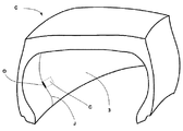
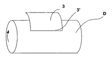
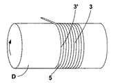
図1は、キャビティ(C)を備えたタイヤ(P)の部分斜視図であり、キャビティの開口部又は口(O)は、上記タイヤの内容積部内へ開口し、上記タイヤの内容積部に隣接した第1の層(3)を形成するゴム異形要素の突合せ継ぎ部(J)の一部上に位置決めされている。 FIG. 1 is a partial perspective view of a tire (P) having a cavity (C), and an opening or mouth (O) of the cavity opens into the inner volume of the tire, and the inner volume of the tire Positioned on a portion of the butt joint (J) of the rubber profiled element forming the adjacent first layer (3).
電子デバイス(図示せず)が開口部(O)を通って直接挿入される。これは、第1の層によって及ぼされる弾性力によってキャビティ(C)内にしっかりと保持され、この第1の層は、上記デバイスをキャビティ内へ導入することにより張力が加えられる。 An electronic device (not shown) is inserted directly through the opening (O). This is held firmly in the cavity (C) by the elastic force exerted by the first layer, which is tensioned by introducing the device into the cavity.
上記第1の層(3)の構成材料の弾性率及び厚さは、その機能を実行できるよう選択されたものでなければならない。当業者であれば、キャビティの位置及び第1の層をその正確な位置に構成する材料の性質に従ってこれらの値を決定することに困難はないであろう。 The elastic modulus and thickness of the constituent material of the first layer (3) must be selected to perform its function. One skilled in the art would have no difficulty in determining these values according to the location of the cavity and the nature of the material that constitutes the first layer at that exact location.
キャビティの寸法形状はこの中に挿入される電子デバイスの寸法形状に合わせて調節される。 The size and shape of the cavity are adjusted in accordance with the size and shape of the electronic device inserted therein.
図1は、第1の層(3)を構成する異形要素の突合せ継ぎ部(J)の向きが実質的に半径方向(ラジアル)であるタイヤを示している。本発明を第1の層(3)を形成するゴム異形要素の突合せ継ぎ部(J)の角度の向きが半径方向の向きとは異なり、円周方向に対し0゜〜90゜であるのがよい状態でちょうど良く実施できることに注目されたい。 FIG. 1 shows a tire in which the orientation of the butt joint (J) of the deformed elements constituting the first layer (3) is substantially radial (radial). In the present invention, the angle direction of the butt joint (J) of the rubber deformed element forming the first layer (3) is different from the radial direction and is 0 ° to 90 ° with respect to the circumferential direction. Note that it can be implemented just in good condition.
これと同様に、キャビティの半径方向位置を、下方領域を補強するビードワイヤを含むビードヒール帯域とそのクラウンの下に位置した部品であるタイヤ(P)の内側クラウンとの間の任意の場所に選択するのがよい。それにもかかわらず、選択された位置は、タイヤの使用中、問題の領域に加わる機能的力と適合する必要がある。 Similarly, the radial position of the cavity is selected anywhere between the bead heel zone containing the bead wire that reinforces the lower region and the inner crown of the tire (P), which is the part located under the crown. It is good. Nevertheless, the selected location needs to match the functional force applied to the area of interest during tire use.
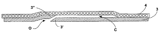
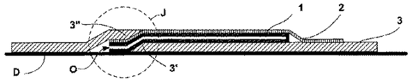
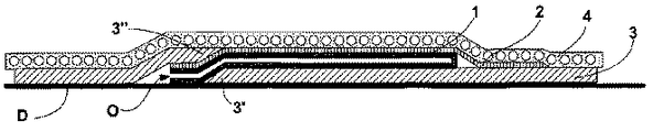
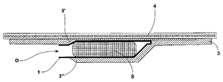
図2は、本発明のキャビティの単純化された実施形態の断面図であり、上記キャビティ(C)は、第1の層(3)と第2の層(4)との間のゴム結合部が局所的に無いことにより形成されている。キャビティ(C)の開口部(O)は、第1の層のリップ(3′),(3″)相互間の溶接継ぎ部の一部上に位置決めされている。 FIG. 2 is a cross-sectional view of a simplified embodiment of the cavity of the present invention, wherein the cavity (C) is a rubber joint between the first layer (3) and the second layer (4). It is formed because there is not locally. The opening (O) of the cavity (C) is positioned on a portion of the weld joint between the lips (3 '), (3 ") of the first layer.
気密材料の数枚の層を必要とするタイヤに関する第1の例示の用途では、第1の層及び第2の層は、同一材料から成るのがよい。 In a first exemplary application for a tire that requires several layers of hermetic material, the first layer and the second layer may be made of the same material.
第2の例示の用途では、第1の層は、気密材料から成り、第2の層は、補強プライから成る。 In the second exemplary application, the first layer is made of an airtight material and the second layer is made of a reinforcing ply.
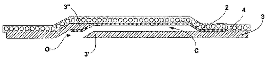
これらの条件下において、そして、タイヤの全体的な気密性を向上させるよう、第1の層(3)を構成する材料とほぼ同じ気密特性を備えた材料で作られていて、内側フェース及び外側フェースを備えた裏当て層(2)を設けると有利な場合があり、この裏当て層(2)は、第2の層(4)の内側フェース全体及びキャビティ(C)に隣接したその外側フェースの一部とゴム結合部を形成する。これら層の外側フェースは、タイヤの内容積部の方へ向けられたフェースとして定義され、外側フェースは、反対側の方へ向いたフェースである。 Under these conditions and to improve the overall tightness of the tire, it is made of a material with substantially the same hermetic properties as the material constituting the first layer (3), the inner face and the outer It may be advantageous to provide a backing layer (2) with a face, this backing layer (2) being the entire inner face of the second layer (4) and its outer face adjacent to the cavity (C). Forming a rubber joint with a part of The outer face of these layers is defined as the face directed towards the inner volume of the tire, the outer face being the face facing the opposite side.
事実、キャビティ(C)に隣接していない裏当て層(2)の外側フェースの一部と第1の層(3)との間に形成されたゴム結合部により、キャビティ(C)の縁部のところの適正な気密性を保証するよう長さ及び幅がキャビティ(C)の長さ及び幅よりも僅かに大きな裏当て層(2)を設けることが推奨される。 In fact, the edge of the cavity (C) is formed by a rubber bond formed between a portion of the outer face of the backing layer (2) that is not adjacent to the cavity (C) and the first layer (3). However, it is recommended to provide a backing layer (2) whose length and width are slightly larger than the length and width of the cavity (C) to ensure proper hermeticity.
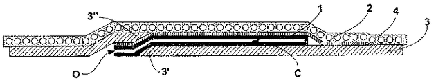
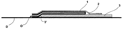
これと同様に、キャビティの表面の保護を強化すると共に検出器モジュールとキャビティの壁との間の摩擦により引き起こされる劣化を回避するために、図4に詳細に示すように、保護層(1)をキャビティ(C)の壁上に配置すると有用な場合がある。 Similarly, to enhance the protection of the cavity surface and to avoid degradation caused by friction between the detector module and the cavity wall, as shown in detail in FIG. 4, a protective layer (1) May be useful to place on the wall of the cavity (C).
この保護層は、延伸性材料の2つの層から成る。非限定的な例として、材料は、弾性材料の中から選択されたもの、例えばゴムであるのがよく、或いはこの目的に適した織編又は非織編織物ベースを選択することにより選択してもよい。延伸性材料は、第1の層(3)にくっつくと共に第2の層(4)又は裏当て層(2)にくっつくよう設計され、この場合、キャビティ(C)は、上記2つの保護層相互間に形成される。 This protective layer consists of two layers of extensible material. As a non-limiting example, the material may be selected from among elastic materials, such as rubber, or selected by selecting a woven or non-woven fabric base suitable for this purpose. Also good. The extensible material is designed to stick to the first layer (3) and to the second layer (4) or the backing layer (2), in which case the cavity (C) has a mutual relationship between the two protective layers. Formed between.
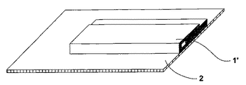
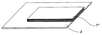
図5及び図6は、長手方向(1′)又は横方向(1″)に折り返された織布から作られた保護層(1)の2つの特定の実施形態を示している。相当大きなサイズの検出器の場合、ベローを側方位置に又は開口部(O)と反対側の部分に設けてキャビティの内容積を増大させるのがよい。 5 and 6 show two specific embodiments of a protective layer (1) made from a woven fabric folded in the longitudinal direction (1 ') or the transverse direction (1 "). In this case, the bellows may be provided at a lateral position or at a portion opposite to the opening (O) to increase the internal volume of the cavity.
上述のキャビティ(C)の形態の各々において、キャビティ(C)は、第1の層(3)と第2の層(4)又は裏当て層(2)との間又は保護層それ自体相互間にゴム結合部が局所的に無いことによって形成される。その特定の作用効果をタイヤ内のその正確な位置に得るためには、幾つかの技術を用いるのがよい。 In each of the cavity (C) configurations described above, the cavity (C) is between the first layer (3) and the second layer (4) or backing layer (2) or between the protective layers themselves. It is formed by having no rubber joint part locally. Several techniques may be used to obtain that particular effect at its exact location within the tire.
第1の技術は、タイヤの成型中、ブラシ又はスプレーを用いて粘着防止製品を第1の層(3)及びリップ部分(3′)上で局所的に、キャビティ(C)及びその開口部(O)を配置するのが望ましい位置に被着させる工程から成る。この粘着防止製品は、例えば、シリコーンを主成分とする溶液から成るのがよく、その作用効果は、加硫時に、その領域にゴム結合部の形成を阻止することにある。 The first technique is to use a brush or spray to apply the anti-stick product locally on the first layer (3) and the lip portion (3 ') during the molding of the tire, the cavity (C) and its opening ( O) is deposited at the position where it is desirable to place. This anti-sticking product is preferably composed of, for example, a solution containing silicone as a main component, and its effect is to prevent the formation of a rubber bonding portion in the region during vulcanization.
タイヤの製造は、次の工程、即ち、
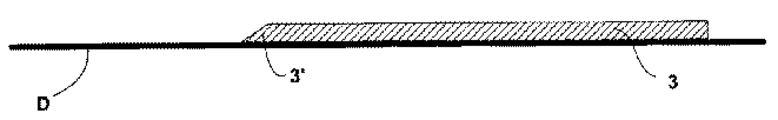
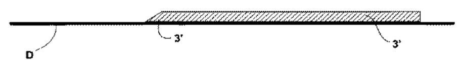
−タイヤ(P)の内容積部に隣接したゴム異形要素の組立体から成り、縁部が突合せ継ぎ部(J)の第1のリップ(3′)を有する第1の層(3)の区分の第1部分を成型ドラム(D)上に配置する工程と、
−粘着防止製品をキャビティ(C)を境界付けるようになった第1の層の領域上及びリップ(3′)の隣接部分上に局所的に付着させる工程と、
−第2のリップ(3″)を有する区分の第2区分を定位置に置くことにより第1の層の区分の位置決めを完了させる工程と、
−突合せ継ぎ部(J)の第1のリップ(3′)と第2のリップ(3″)を互いに合わせる工程と、第1の層とのゴム結合部を形成するゴム異形要素の組立体から成る第2の層(4)を定位置に置く工程と、
−タイヤを形成するゴム異形要素の位置決めを続行して完了させる工程と、
−タイヤを硬化成型機で加硫する工程とから成る。
The manufacture of the tire involves the following steps:
A section of a first layer (3) comprising an assembly of rubber profile elements adjacent to the inner volume of the tire (P), the edge having a first lip (3 ') of the butt joint (J) Arranging the first part of the mold on the molding drum (D);
Applying the anti-stick product locally on the region of the first layer adapted to bound the cavity (C) and on the adjacent part of the lip (3 ');
-Completing the positioning of the section of the first layer by placing the second section of the section with the second lip (3 ") in place;
From the assembly of the rubber profile elements forming the rubber joints with the first layer, and the step of mating the first lip (3 ') and the second lip (3 ") of the butt joint (J); Placing the second layer (4) comprising:
-Continuing and completing the positioning of the rubber profile elements forming the tire;
And vulcanizing the tire with a curing molding machine.
粘着防止製品があることにより、キャビティ(C)が形成される正確な場所で局所的に第1の層と第2の層との間のゴム結合部の形成が阻止され、上記粘着防止組成物をリップ上に被着させることにより、開口部(O)をキャビティ(C)の高さ位置に形成することができる。 Due to the presence of the anti-sticking product, the formation of the rubber joint between the first layer and the second layer is locally blocked at the exact location where the cavity (C) is formed, and the anti-sticking composition Can be formed at the height of the cavity (C).
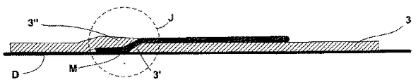
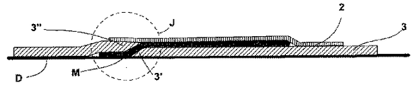
粘着防止溶液の塗布に代わる手段は、ゴム結合部の局所的形成を阻止するよう設計された着脱自在な中間要素(M)をキャビティ(C)及びその開口部(O)の高さ位置に位置決めすることにあり、その使用方法が図7〜図10に示されている。この中間要素は、シリコーンを主成分とする材料から成っていてもよく、或いは、耐粘着性被膜、例えばデュ・ポン・ド・ヌムール社により市販されているテフロン(登録商標)タイプのポリテトラフルオロエチレンを主成分とする被膜で覆われたものであってもよい。 An alternative to applying an anti-tack solution is to position a removable intermediate element (M) designed to prevent local formation of the rubber joint at the height of the cavity (C) and its opening (O). The method of use is shown in FIGS. This intermediate element may consist of a silicone-based material or an anti-stick coating, for example Teflon type polytetrafluoropolymer marketed by the company du Pont de Nemours. What was covered with the film which has ethylene as a main component may be used.
この場合、この方法は、次の工程、即ち、
−タイヤ(P)の内容積部に隣接したゴム異形要素の組立体から成り、縁部が突合せ継ぎ部(J)の第1のリップ(3′)を有する第1の層(3)の区分の第1部分を成型ドラム(D)上に配置する工程と、
−フェースの両方が粘着防止材料で被覆された着脱自在な中間要素(M)をキャビティ(C)を境界付けるようになった区分の第1部分の領域上及び隣接のリップ(3′)上に位置決めする工程と、
−第2のリップ(3″)を有する区分の第2区分を定位置に置くことにより第1の層の区分の位置決めを完了させる工程と、
−第1のリップ(3′)と第2のリップ(3″)を中間パッチ(M)により被覆されている部分を除き、突合せ継ぎ部(J)の長さに沿って互いに合わせる工程と、
−第1の層とのゴム結合部を形成するゴム異形要素の組立体から成る第2の層(4)を定位置に置く工程と、
−タイヤを形成するゴム異形要素の位置決めを続行する工程と、
−タイヤを加硫する工程と、
−中間要素(M)を開口部(O)から抜き取る工程とから成る。
In this case, the method comprises the following steps:
A section of a first layer (3) comprising an assembly of rubber profile elements adjacent to the inner volume of the tire (P), the edge having a first lip (3 ') of the butt joint (J) Arranging the first part of the mold on the molding drum (D);
A removable intermediate element (M), both of which are coated with an anti-adhesive material, on the area of the first part of the section which is intended to bound the cavity (C) and on the adjacent lip (3 ') Positioning, and
-Completing the positioning of the section of the first layer by placing the second section of the section with the second lip (3 ") in place;
-Aligning the first lip (3 ') and the second lip (3 ") with each other along the length of the butt joint (J) except for the portion covered by the intermediate patch (M);
Placing the second layer (4) consisting of an assembly of rubber profiled elements forming a rubber bond with the first layer in place;
-Continuing the positioning of the rubber profile elements forming the tire;
-Vulcanizing the tire;
-Drawing the intermediate element (M) from the opening (O).
もう1つの別法は、タイヤ内に永続的にとどまり、保護層(1)として役立つようになった中間要素を位置決めすることにある。上述したように、上記要素は、延伸性材料の2つの層又は折り返された1つの層から成るのがよく、かかる折返し層の接触状態にあるフェースは、粘着防止製品(1′,1″)で覆われている。 Another alternative consists in positioning an intermediate element that stays permanently in the tire and has come to serve as a protective layer (1). As mentioned above, the element may consist of two layers of extensible material or one folded layer, the face in contact with such a folded layer being an anti-stick product (1 ′, 1 ″) Covered with.
この場合、この方法は、次の工程、即ち、
−タイヤ(P)の内容積部に隣接したゴム異形要素の組立体から成り、縁部が突合せ継ぎ部(J)の第1のリップ(3′)を有する第1の層(3)の区分の第1部分を成型ドラム(D)上に配置する工程と、
−延伸性材料の2つの層から成っていて、フェースの両方が粘着防止材料で被覆された中間要素(1,1′,1″)をキャビティ(C)を境界付けるようになった区分の第1部分の領域上及び隣接のリップ(3′)上に位置決めする工程と、
−第2のリップ(3″)を有する区分の第2区分を定位置に置くことにより第1の層の区分の位置決めを完了させる工程と、
−第1のリップ(3′)と第2のリップ(3″)を中間パッチ(M)により被覆されている部分を除き、突合せ継ぎ部(J)の長さに沿って互いに合わせる工程と、
−第1の層とのゴム結合部を形成するゴム異形要素の組立体から成る第2の層(4)を定位置に置く工程と、
−タイヤを形成するゴム異形要素の位置決めを続行する工程と、
−タイヤを加硫する工程とから成る。
In this case, the method comprises the following steps:
A section of a first layer (3) comprising an assembly of rubber profile elements adjacent to the inner volume of the tire (P), the edge having a first lip (3 ') of the butt joint (J) Arranging the first part of the mold on the molding drum (D);
The second part of the section, which consists of two layers of extensible material, both of which faces the cavity (C) with an intermediate element (1, 1 ', 1 "), both of which are coated with anti-stick material Positioning on a partial area and on an adjacent lip (3 ');
-Completing the positioning of the section of the first layer by placing the second section of the section with the second lip (3 ") in place;
-Aligning the first lip (3 ') and the second lip (3 ") with each other along the length of the butt joint (J) except for the portion covered by the intermediate patch (M);
Placing the second layer (4) consisting of an assembly of rubber profiled elements forming a rubber bond with the first layer in place;
-Continuing the positioning of the rubber profile elements forming the tire;
-Vulcanizing the tire.
裏当て層(2)を構成するゴム異形要素を、図11〜図14に示すようにリップを互いに合わせる前であって中間要素を位置決めした直後、或いは、図7〜図10に示すようにリップを互いに合わせた後に位置決めするのがよく、この場合、裏当て層(2)を形成する異形要素と保護層及び裏当て層を形成する中間要素をあらかじめ組み立てることが提案される。 The rubber deformed elements constituting the backing layer (2) are formed before the lips are aligned with each other as shown in FIGS. 11 to 14 immediately after the intermediate elements are positioned, or as shown in FIGS. Are preferably positioned after they have been brought together, in which case it is proposed to pre-assemble the profile elements forming the backing layer (2) and the intermediate elements forming the protective and backing layers.
本発明のタイヤは一般に、タイヤを構成するゴム異形要素の区分を円周方向に堆積させる円筒形又はドーナツ形の金型で製造される。 The tire of the present invention is generally manufactured with a cylindrical or donut-shaped mold in which sections of the rubber profile elements constituting the tire are deposited in the circumferential direction.
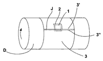
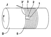
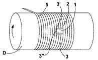
例示の目的で、図15は、円筒形ドラム(D)上への、第1のリップ(3′)を備えた第1の層(3)を形成する区分の第1部分の位置決め工程を示す概略斜視図である。図16は、中間要素(1)及び裏当て層(2)の位置決め工程を示す図であり、図17は、2つのリップ(3′),(3″)を合わせることから成る工程の完了状態を示している。 For illustrative purposes, FIG. 15 shows the positioning process of the first part of the section forming the first layer (3) with the first lip (3 ′) onto the cylindrical drum (D). It is a schematic perspective view. FIG. 16 shows the positioning process of the intermediate element (1) and the backing layer (2), and FIG. 17 shows the completed state of the process comprising the joining of the two lips (3 ′), (3 ″) Is shown.
しかしながら、本発明は、ゴム異形要素をコイル状ストリップの形態で位置決めする方法によっても実施できる。 However, the invention can also be implemented by a method of positioning the rubber profile element in the form of a coiled strip.
かくして、図18は、円筒形ドラム(D)上への第1のリップ(3′)を備えた第1の層(3)を形成する区分の第1部分の位置決め工程を示す概略斜視図である。図19は、中間要素(1)及び裏当て層の位置決めから成る工程を示す図である。図20は、キャビティ(C)の開口部(O)を有するようになった継ぎ部を形成する2つの互いに接触したターンの2つのリップ(3′),(3″)を合わせた後のドラム(D)上への第1の層の堆積から成る工程の完了状態を示す図である。図18、図19及び図20は、円筒形ドラム上へのコイル状ストリップの位置決め工程を示している。 Thus, FIG. 18 is a schematic perspective view showing the positioning process of the first part of the section forming the first layer (3) with the first lip (3 ′) on the cylindrical drum (D). is there. FIG. 19 shows the process consisting of positioning of the intermediate element (1) and the backing layer. FIG. 20 shows the drum after combining two lips (3 ′), (3 ″) of two mutually contacting turns that form a seam with an opening (O) in the cavity (C). Fig. 18 (D) shows the completed state of the process consisting of the deposition of the first layer on top, Fig. 18, 19 and 20 show the step of positioning the coiled strip on the cylindrical drum. .
ドラムに代えてタイヤの内容積部の形状を有する支持体を用いてもよいことは言うまでもない。 Needless to say, a support having the shape of the inner volume of the tire may be used instead of the drum.
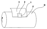
図21は、検出器(S)がキャビティ(C)内に配置された状況の断面図である。 FIG. 21 is a cross-sectional view of a situation where the detector (S) is disposed in the cavity (C).
本発明は、その実施方法と関連した多くの特定の利点を奏することに注目されたい。 It should be noted that the present invention has many specific advantages associated with its implementation.
第1の利点は、タイヤの内面に直接設けられるポケットを形成した場合の利点のうちの幾つかが回避されるということにある。事実、まさにその場合において、上記ポケットは硬化メンブレンを成型機内で拡張させた場合に、メンブレンにより変位する傾向があり、その結果、粘着不良及び製造欠陥が生じることが判明している。 The first advantage is that some of the advantages of forming pockets directly on the inner surface of the tire are avoided. In fact, in that case, it has been found that the pockets tend to be displaced by the membrane when the cured membrane is expanded in a molding machine, resulting in poor adhesion and manufacturing defects.
さらに、ポケットを受け入れるようになった表面を作製する工程が回避され、これにより、タイヤの製造中、相当な時間が節約される。 Furthermore, the process of creating a surface adapted to receive a pocket is avoided, which saves considerable time during the manufacture of the tire.
第2の利点は、本発明の方法により製造されたタイヤが着脱自在な監視装置を保持するよう内面に設けられた支持体を除去するようタイヤの内面を作製する必要無く、連続した再トレッド形成作業を受けることができる性能が高いということにある。なお、かかるタイヤ内面の作製を行うと、加硫作業中に硬化メンブレンが損傷する場合がある。 A second advantage is that the tire manufactured by the method of the present invention can be continuously re-treaded without the need to produce the inner surface of the tire so as to remove the support provided on the inner surface to hold the removable monitoring device. The ability to receive work is high. When the tire inner surface is produced, the cured membrane may be damaged during the vulcanization operation.
1 保護層
2 裏当て層
3 第1の層
3′,3″ リップ
4 第2の層
C キャビティ
D 電子監視モジュール
J 突合せ継ぎ部
M 中間パッチ
O 開口部
P タイヤ
S 検出器
DESCRIPTION OF
Claims (18)
−タイヤ(P)の内容積部に隣接したゴム異形要素の組立体から成り、縁部が突合せ継ぎ部(J)の第1のリップ(3′)を有する第1の層(3)の区分の第1部分を成型ドラム(D)上に配置する工程と、
−粘着防止製品をキャビティ(C)を境界付けるようになった第1の層の領域上及びリップ(3′)の隣接部分上に局所的に付着させる工程と、
−第2のリップ(3″)を有する前記区分の第2区分を定位置に置くことにより前記第1の層の区分の位置決めを完了させる工程と、
−突合せ継ぎ部(J)の第1のリップ(3′)と第2のリップ(3″)を互いに合わせる工程と、前記第1の層とのゴム結合部を形成するゴム異形要素の組立体から成る第2の層(4)を定位置に置く工程と、
−タイヤを形成するゴム異形要素の位置決めを続行する工程と、
−タイヤを加硫する工程とから成ることを特徴とする方法。 A method for manufacturing a tire (P), comprising:
A section of a first layer (3) comprising an assembly of rubber profile elements adjacent to the inner volume of the tire (P), the edge having a first lip (3 ') of the butt joint (J) Arranging the first part of the mold on the molding drum (D);
Applying the anti-stick product locally on the region of the first layer adapted to bound the cavity (C) and on the adjacent part of the lip (3 ');
-Completing the positioning of the section of the first layer by placing the second section of the section having a second lip (3 ") in place;
The assembly of the first and second lip (3 ') and the third lip (3 ") of the butt joint (J) with each other and a rubber profile element forming a rubber joint with the first layer; Placing the second layer (4) consisting of:
-Continuing the positioning of the rubber profile elements forming the tire;
A method comprising the step of vulcanizing the tire.
−タイヤ(P)の内容積部に隣接したゴム異形要素の組立体から成り、縁部が突合せ継ぎ部(J)の第1のリップ(3′)を有する第1の層(3)の区分の第1部分を成型ドラム(D)上に配置する工程と、
−フェースのうちの少なくとも1つが粘着防止材料で被覆された中間要素(1,1′,1″,M)をキャビティ(C)を境界付けるようになった区分の第1部分の領域上及び隣接のリップ(3′)上に位置決めする工程と、
−第2のリップ(3″)を有する前記区分の第2区分を定位置に置くことにより前記第1の層の区分の位置決めを完了させる工程と、
−第1のリップ(3′)と第2のリップ(3″)を互いに合わせる工程と、
−前記第1の層とのゴム結合部を形成するゴム異形要素の組立体から成る第2の層(4)を定位置に置く工程と、
−タイヤを形成するゴム異形要素の位置決めを続行する工程と、
−タイヤを加硫する工程とから成ることを特徴とする方法。 A method for manufacturing a tire (P), comprising:
A section of a first layer (3) comprising an assembly of rubber profile elements adjacent to the inner volume of the tire (P), the edge having a first lip (3 ') of the butt joint (J) Arranging the first part of the mold on the molding drum (D);
On and adjacent to the region of the first part of the section in which at least one of the faces is bounded by a cavity (C) with an intermediate element (1, 1 ′, 1 ″, M) coated with an anti-stick material Positioning on the lip (3 ') of
-Completing the positioning of the section of the first layer by placing the second section of the section having a second lip (3 ") in place;
-Mating the first lip (3 ') and the second lip (3 ") with each other;
-Placing in place a second layer (4) comprising an assembly of rubber profiled elements forming a rubber joint with the first layer;
-Continuing the positioning of the rubber profile elements forming the tire;
A method comprising the step of vulcanizing the tire.
Applications Claiming Priority (2)
| Application Number | Priority Date | Filing Date | Title |
|---|---|---|---|
| FR0402886A FR2867721A1 (en) | 2004-03-18 | 2004-03-18 | POCKET HOLDING ELECTRONIC SENSOR |
| FR0402886 | 2004-03-18 |
Publications (3)
| Publication Number | Publication Date |
|---|---|
| JP2005297963A true JP2005297963A (en) | 2005-10-27 |
| JP2005297963A5 JP2005297963A5 (en) | 2008-04-24 |
| JP4884692B2 JP4884692B2 (en) | 2012-02-29 |
Family
ID=34896666
Family Applications (1)
| Application Number | Title | Priority Date | Filing Date |
|---|---|---|---|
| JP2005117476A Expired - Fee Related JP4884692B2 (en) | 2004-03-18 | 2005-03-18 | Electronic detector holding pocket |
Country Status (8)
| Country | Link |
|---|---|
| US (1) | US7556074B2 (en) |
| EP (1) | EP1586468B1 (en) |
| JP (1) | JP4884692B2 (en) |
| CN (1) | CN100560388C (en) |
| AT (1) | ATE510709T1 (en) |
| AU (1) | AU2005201161A1 (en) |
| BR (1) | BRPI0500897B1 (en) |
| FR (1) | FR2867721A1 (en) |
Cited By (3)
| Publication number | Priority date | Publication date | Assignee | Title |
|---|---|---|---|---|
| WO2007114204A1 (en) * | 2006-03-29 | 2007-10-11 | The Yokohama Rubber Co., Ltd. | Method for producing pneumatic tire |
| JP2013508209A (en) * | 2009-10-21 | 2013-03-07 | レマ ティプ トップ ゲーエムベーハー | Fastening system for attaching a cage to an elastomeric member |
| JP2018501366A (en) * | 2014-12-19 | 2018-01-18 | コンパニー ゼネラール デ エタブリッスマン ミシュラン | Tires ready to receive elements on the surface |
Families Citing this family (16)
| Publication number | Priority date | Publication date | Assignee | Title |
|---|---|---|---|---|
| DE10243441B4 (en) * | 2002-09-18 | 2004-12-30 | Continental Aktiengesellschaft | Tire transponder |
| US7770444B2 (en) * | 2005-12-13 | 2010-08-10 | Michelin Recherche Et Technique S.A. | Patch for fixing an electronic system to a tire |
| FR2902173B1 (en) | 2006-06-09 | 2008-12-05 | Michelin Soc Tech | PNEUMATIC VALVE AND METHOD FOR DISASSEMBLING THE SAME |
| WO2008147409A1 (en) * | 2007-05-25 | 2008-12-04 | Societe De Technologie Michelin | Method to protect tire electronics |
| FR2934967B1 (en) * | 2008-08-14 | 2010-08-13 | Michelin Soc Tech | PNEUMATIC WITHOUT AIR CHAMBER HAVING A SLOTTED INNER GUM AND METHOD OF MANUFACTURING THE SAME |
| FR2937284B1 (en) | 2008-10-20 | 2010-11-19 | Michelin Soc Tech | INSTRUMENT PNEUMATIC AND PNEUMATIC BODY |
| US8281827B2 (en) * | 2008-11-06 | 2012-10-09 | The Yokohama Rubber Co., Ltd. | Pneumatic tire |
| FR2981010B1 (en) * | 2011-10-05 | 2014-06-13 | Michelin Soc Tech | KIT AND METHOD FOR TEMPORARILY FIXING AN ELECTRONIC DEVICE ON A SUPPORT OF A PNEUMATIC ENVELOPE |
| US20130133800A1 (en) * | 2011-11-29 | 2013-05-30 | Jean-Claude Patrice Philippe Griffoin | System for attaching an electronic device or other item to a pneumatic tire |
| KR101775797B1 (en) * | 2015-11-30 | 2017-09-06 | 한국타이어 주식회사 | A tire silent foam fixing structure comprising a silent foam fixing band and a tire having thereof |
| FR3063041B1 (en) * | 2017-02-17 | 2019-05-03 | Compagnie Generale Des Etablissements Michelin | DEVICE FOR FASTENING A PNEUMATIC ENVELOPE OF AN ELECTRONIC MEMBER. |
| JP6756004B1 (en) * | 2019-05-08 | 2020-09-16 | Toyo Tire株式会社 | Tires and tire manufacturing methods |
| JP6756021B1 (en) * | 2019-08-23 | 2020-09-16 | Toyo Tire株式会社 | Tires and tire manufacturing methods |
| DE102019215069A1 (en) * | 2019-09-30 | 2021-04-01 | Continental Reifen Deutschland Gmbh | tires |
| IT202200015150A1 (en) | 2022-07-19 | 2024-01-19 | Bridgestone Europe Nv Sa | TYRE EQUIPPED WITH AN ELECTRONIC DEVICE |
| JP7323023B1 (en) * | 2022-08-03 | 2023-08-08 | 住友ゴム工業株式会社 | tire |
Citations (12)
| Publication number | Priority date | Publication date | Assignee | Title |
|---|---|---|---|---|
| JPH0713505U (en) * | 1993-08-18 | 1995-03-07 | 株式会社ブリヂストン | Pneumatic tire |
| JPH0867117A (en) * | 1994-06-03 | 1996-03-12 | Bridgestone Corp | Method for monitoring state of tire for vehicle and monitor device built-in tire |
| JPH11216781A (en) * | 1997-11-28 | 1999-08-10 | Sumitomo Rubber Ind Ltd | Pneumatic tire and manufacture of pneumatic tire |
| JPH11278021A (en) * | 1998-02-10 | 1999-10-12 | Bridgestone Corp | Tire having monitoring device |
| JP2000168321A (en) * | 1998-12-04 | 2000-06-20 | Bridgestone Corp | Method for adjusting pneumatic tire for joining electronic monitor device |
| JP2001063325A (en) * | 1999-08-27 | 2001-03-13 | Yokohama Rubber Co Ltd:The | Pneumatic tire with transponder buried and manufacture thereof |
| JP2002214060A (en) * | 2001-01-12 | 2002-07-31 | Yokohama Rubber Co Ltd:The | Transponder, attached to tire, transponder-attached tire, and manufacturing method thereof |
| JP2002541003A (en) * | 1999-11-24 | 2002-12-03 | ミシュラン ルシェルシェ エ テクニク ソシエテ アノニム | Monitored car tires and monitor holding assemblies |
| EP1318032A2 (en) * | 2001-12-05 | 2003-06-11 | Continental Aktiengesellschaft | Method of manufacturing a vehicle tyre provided with a transponder |
| WO2003070496A1 (en) * | 2002-02-18 | 2003-08-28 | Bridgestone/Firestone North American Tire, Llc | Attachment method for tire tag |
| JP2003525804A (en) * | 2000-03-09 | 2003-09-02 | ブリヂストン/フアイヤーストーン・ノース・アメリカン・タイヤ・エルエルシー | Method and apparatus for powering a tire monitor |
| WO2003095243A1 (en) * | 2002-05-07 | 2003-11-20 | Bridgestone/Firestone North American Tire, Llc | Monitoring device and patch assembly |
Family Cites Families (5)
| Publication number | Priority date | Publication date | Assignee | Title |
|---|---|---|---|---|
| GB1434732A (en) * | 1972-05-23 | 1976-05-05 | Dunlop Ltd | Pneumatic tyres and methods of manufacture thereof |
| DE69406224T2 (en) * | 1993-08-18 | 1998-03-19 | Bridgestone Corp | Pneumatic tire with a transponder, device and method for picking up and reading from a transponder |
| DE10209580B4 (en) * | 2002-03-05 | 2014-01-30 | Goodyear Dunlop Tires Germany Gmbh | Vehicle tires with integrated transponder |
| DE10243441B4 (en) * | 2002-09-18 | 2004-12-30 | Continental Aktiengesellschaft | Tire transponder |
| US6978669B2 (en) * | 2003-12-22 | 2005-12-27 | The Goodyear Tire & Rubber Company | Method and assembly of sensor ready tires |
-
2004
- 2004-03-18 FR FR0402886A patent/FR2867721A1/en active Pending
-
2005
- 2005-03-16 EP EP05102052A patent/EP1586468B1/en not_active Not-in-force
- 2005-03-16 AT AT05102052T patent/ATE510709T1/en not_active IP Right Cessation
- 2005-03-17 AU AU2005201161A patent/AU2005201161A1/en not_active Abandoned
- 2005-03-17 CN CNB2005100554357A patent/CN100560388C/en not_active Expired - Fee Related
- 2005-03-17 BR BRPI0500897-2A patent/BRPI0500897B1/en not_active IP Right Cessation
- 2005-03-18 US US11/083,215 patent/US7556074B2/en not_active Expired - Fee Related
- 2005-03-18 JP JP2005117476A patent/JP4884692B2/en not_active Expired - Fee Related
Patent Citations (12)
| Publication number | Priority date | Publication date | Assignee | Title |
|---|---|---|---|---|
| JPH0713505U (en) * | 1993-08-18 | 1995-03-07 | 株式会社ブリヂストン | Pneumatic tire |
| JPH0867117A (en) * | 1994-06-03 | 1996-03-12 | Bridgestone Corp | Method for monitoring state of tire for vehicle and monitor device built-in tire |
| JPH11216781A (en) * | 1997-11-28 | 1999-08-10 | Sumitomo Rubber Ind Ltd | Pneumatic tire and manufacture of pneumatic tire |
| JPH11278021A (en) * | 1998-02-10 | 1999-10-12 | Bridgestone Corp | Tire having monitoring device |
| JP2000168321A (en) * | 1998-12-04 | 2000-06-20 | Bridgestone Corp | Method for adjusting pneumatic tire for joining electronic monitor device |
| JP2001063325A (en) * | 1999-08-27 | 2001-03-13 | Yokohama Rubber Co Ltd:The | Pneumatic tire with transponder buried and manufacture thereof |
| JP2002541003A (en) * | 1999-11-24 | 2002-12-03 | ミシュラン ルシェルシェ エ テクニク ソシエテ アノニム | Monitored car tires and monitor holding assemblies |
| JP2003525804A (en) * | 2000-03-09 | 2003-09-02 | ブリヂストン/フアイヤーストーン・ノース・アメリカン・タイヤ・エルエルシー | Method and apparatus for powering a tire monitor |
| JP2002214060A (en) * | 2001-01-12 | 2002-07-31 | Yokohama Rubber Co Ltd:The | Transponder, attached to tire, transponder-attached tire, and manufacturing method thereof |
| EP1318032A2 (en) * | 2001-12-05 | 2003-06-11 | Continental Aktiengesellschaft | Method of manufacturing a vehicle tyre provided with a transponder |
| WO2003070496A1 (en) * | 2002-02-18 | 2003-08-28 | Bridgestone/Firestone North American Tire, Llc | Attachment method for tire tag |
| WO2003095243A1 (en) * | 2002-05-07 | 2003-11-20 | Bridgestone/Firestone North American Tire, Llc | Monitoring device and patch assembly |
Cited By (4)
| Publication number | Priority date | Publication date | Assignee | Title |
|---|---|---|---|---|
| WO2007114204A1 (en) * | 2006-03-29 | 2007-10-11 | The Yokohama Rubber Co., Ltd. | Method for producing pneumatic tire |
| US8900389B2 (en) | 2006-03-29 | 2014-12-02 | The Yokohama Rubber Co., Ltd. | Method for producing pneumatic tire |
| JP2013508209A (en) * | 2009-10-21 | 2013-03-07 | レマ ティプ トップ ゲーエムベーハー | Fastening system for attaching a cage to an elastomeric member |
| JP2018501366A (en) * | 2014-12-19 | 2018-01-18 | コンパニー ゼネラール デ エタブリッスマン ミシュラン | Tires ready to receive elements on the surface |
Also Published As
| Publication number | Publication date |
|---|---|
| BRPI0500897B1 (en) | 2014-12-02 |
| US7556074B2 (en) | 2009-07-07 |
| EP1586468A3 (en) | 2010-03-17 |
| FR2867721A1 (en) | 2005-09-23 |
| ATE510709T1 (en) | 2011-06-15 |
| JP4884692B2 (en) | 2012-02-29 |
| CN100560388C (en) | 2009-11-18 |
| US20050217774A1 (en) | 2005-10-06 |
| BRPI0500897A (en) | 2005-11-01 |
| EP1586468A2 (en) | 2005-10-19 |
| EP1586468B1 (en) | 2011-05-25 |
| CN1669836A (en) | 2005-09-21 |
| AU2005201161A1 (en) | 2005-10-06 |
Similar Documents
| Publication | Publication Date | Title |
|---|---|---|
| JP4884692B2 (en) | Electronic detector holding pocket | |
| JP2010514525A (en) | Inflatable facial seal for respiratory mask and method of manufacturing the same | |
| JP2009154320A (en) | Pneumatic tire manufacturing method and pneumatic tire | |
| CA2323888C (en) | Method of manufacturing sealant-containing tires, and sealant-containing tire | |
| JP2007331295A (en) | Manufacturing method of pneumatic tire | |
| JP3567431B2 (en) | Tubeless tire and method of manufacturing the same | |
| JPH0785915B2 (en) | Method of manufacturing inner bladder for tire molding machine and inner bladder | |
| JP2009208444A (en) | Method for molding of inner liner | |
| TW201323188A (en) | Branch pipe lining material, producing method thereof, and branch pipe lining method | |
| JP2007050538A (en) | Manufacturing method of reinforcing layer, manufacturing method of air bladder and molding drum | |
| EP0458436A2 (en) | Method for manufacturing curing envelope for use in tire retreading | |
| JP2011224907A (en) | Method of manufacturing pneumatic tire | |
| JP2007160833A (en) | Manufacturing method of annular hollow body | |
| JPS62278026A (en) | Manufacture of retreaded tire | |
| JPH02175352A (en) | Manufacture of air bag | |
| JPH1034751A (en) | Patch vulcanizing method for large rubber product | |
| JP2007160844A (en) | Manufacturing method of annular hollow body | |
| JP2007050539A (en) | Manufacturing method of reinforcing layer and manufacturing method of air bladder | |
| JP2007130798A (en) | Manufacturing method of annular hollow body | |
| JP6728947B2 (en) | Rubber tape, rubber tape composite, and method for producing the same | |
| JP2007050537A (en) | Manufacturing method of reinforcing layer and manufacturing method of air bladder | |
| KR101414436B1 (en) | Tire manufacturing method and tire manufacturing apparatus | |
| WO2019124148A1 (en) | Tire and method for fixing porous body | |
| RU2452524C2 (en) | Inflatable face seal for respiratory mask and method for making such face seal | |
| JPH0459346A (en) | Pneumatic tire and manufacture thereof |
Legal Events
| Date | Code | Title | Description |
|---|---|---|---|
| A521 | Request for written amendment filed |
Free format text: JAPANESE INTERMEDIATE CODE: A523 Effective date: 20080307 |
|
| A621 | Written request for application examination |
Free format text: JAPANESE INTERMEDIATE CODE: A621 Effective date: 20080307 |
|
| A977 | Report on retrieval |
Free format text: JAPANESE INTERMEDIATE CODE: A971007 Effective date: 20101220 |
|
| A131 | Notification of reasons for refusal |
Free format text: JAPANESE INTERMEDIATE CODE: A131 Effective date: 20101227 |
|
| A521 | Request for written amendment filed |
Free format text: JAPANESE INTERMEDIATE CODE: A523 Effective date: 20110328 |
|
| TRDD | Decision of grant or rejection written | ||
| A01 | Written decision to grant a patent or to grant a registration (utility model) |
Free format text: JAPANESE INTERMEDIATE CODE: A01 Effective date: 20111107 |
|
| A01 | Written decision to grant a patent or to grant a registration (utility model) |
Free format text: JAPANESE INTERMEDIATE CODE: A01 |
|
| A61 | First payment of annual fees (during grant procedure) |
Free format text: JAPANESE INTERMEDIATE CODE: A61 Effective date: 20111207 |
|
| FPAY | Renewal fee payment (event date is renewal date of database) |
Free format text: PAYMENT UNTIL: 20141216 Year of fee payment: 3 |
|
| R150 | Certificate of patent or registration of utility model |
Ref document number: 4884692 Country of ref document: JP Free format text: JAPANESE INTERMEDIATE CODE: R150 Free format text: JAPANESE INTERMEDIATE CODE: R150 |
|
| R250 | Receipt of annual fees |
Free format text: JAPANESE INTERMEDIATE CODE: R250 |
|
| R250 | Receipt of annual fees |
Free format text: JAPANESE INTERMEDIATE CODE: R250 |
|
| R250 | Receipt of annual fees |
Free format text: JAPANESE INTERMEDIATE CODE: R250 |
|
| R250 | Receipt of annual fees |
Free format text: JAPANESE INTERMEDIATE CODE: R250 |
|
| LAPS | Cancellation because of no payment of annual fees |