JP2005295046A - 電気回路装置 - Google Patents
電気回路装置 Download PDFInfo
- Publication number
- JP2005295046A JP2005295046A JP2004104846A JP2004104846A JP2005295046A JP 2005295046 A JP2005295046 A JP 2005295046A JP 2004104846 A JP2004104846 A JP 2004104846A JP 2004104846 A JP2004104846 A JP 2004104846A JP 2005295046 A JP2005295046 A JP 2005295046A
- Authority
- JP
- Japan
- Prior art keywords
- driver
- electric circuit
- controller
- circuit device
- housing
- Prior art date
- Legal status (The legal status is an assumption and is not a legal conclusion. Google has not performed a legal analysis and makes no representation as to the accuracy of the status listed.)
- Granted
Links
Images
Classifications
-
- H—ELECTRICITY
- H05—ELECTRIC TECHNIQUES NOT OTHERWISE PROVIDED FOR
- H05K—PRINTED CIRCUITS; CASINGS OR CONSTRUCTIONAL DETAILS OF ELECTRIC APPARATUS; MANUFACTURE OF ASSEMBLAGES OF ELECTRICAL COMPONENTS
- H05K7/00—Constructional details common to different types of electric apparatus
- H05K7/20—Modifications to facilitate cooling, ventilating, or heating
- H05K7/20845—Modifications to facilitate cooling, ventilating, or heating for automotive electronic casings
- H05K7/20854—Heat transfer by conduction from internal heat source to heat radiating structure
-
- H—ELECTRICITY
- H05—ELECTRIC TECHNIQUES NOT OTHERWISE PROVIDED FOR
- H05K—PRINTED CIRCUITS; CASINGS OR CONSTRUCTIONAL DETAILS OF ELECTRIC APPARATUS; MANUFACTURE OF ASSEMBLAGES OF ELECTRICAL COMPONENTS
- H05K7/00—Constructional details common to different types of electric apparatus
- H05K7/20—Modifications to facilitate cooling, ventilating, or heating
- H05K7/2089—Modifications to facilitate cooling, ventilating, or heating for power electronics, e.g. for inverters for controlling motor
- H05K7/209—Heat transfer by conduction from internal heat source to heat radiating structure
-
- H—ELECTRICITY
- H10—SEMICONDUCTOR DEVICES; ELECTRIC SOLID-STATE DEVICES NOT OTHERWISE PROVIDED FOR
- H10W—GENERIC PACKAGES, INTERCONNECTIONS, CONNECTORS OR OTHER CONSTRUCTIONAL DETAILS OF DEVICES COVERED BY CLASS H10
- H10W90/00—Package configurations
Landscapes
- Engineering & Computer Science (AREA)
- Microelectronics & Electronic Packaging (AREA)
- Physics & Mathematics (AREA)
- Thermal Sciences (AREA)
- Cooling Or The Like Of Electrical Apparatus (AREA)
- Electronic Switches (AREA)
- Connection Or Junction Boxes (AREA)
Abstract
【解決手段】 駆動信号に基づいて制御されて電気負荷への通電を断続する半導体リレーを複数個有する駆動器2と、駆動信号を駆動器2に出力する制御器1とを備え、駆動器2が1つの筐体4に複数個収納され、駆動信号は、制御器1から複数個の駆動器2へシリアル通信で伝送される。これによると、シリアル通信であるため、駆動信号を伝送する通信線および通信用コネクタ端子の数が少なくなり、電気回路装置を小型にすることができる。また、シリアル通信であるため、駆動器2を追加する場合でも、制御器1はマイコンのソフト変更のみ行えばよく、制御器1と駆動器2との間の配線もシリアル通信線のみ追加すればよく、したがって、車種毎のバリエーション対応が容易である。
【選択図】 図2
Description
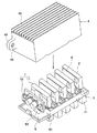
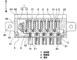
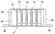
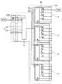
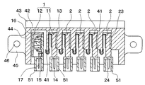
本発明の第1実施形態について説明する。図1は第1実施形態に係る電気回路装置の分解斜視図、図2は図1の電気回路装置の断面図、図3は図2の筐体4の底面図、図4は図1の電気回路装置の等価回路図である。
本発明の第2実施形態について説明する。本実施形態の電気回路装置は、第1実施形態のバスバー3およびカバー5を廃止している。図5は第2実施形態に係る電気回路装置の断面図である。第1実施形態と同一もしくは均等部分には同一の符号を付し、その説明を省略する。
Claims (9)
- 駆動信号に基づいて制御されて電気負荷(100)への通電を断続する半導体リレー(21)を複数個有する駆動器(2)と、前記駆動信号を前記駆動器(2)に出力する制御器(1)とを備え、
前記駆動器(2)が1つの筐体(4)に複数個収納され、
前記駆動信号は、前記制御器(1)から前記複数個の駆動器(2)へシリアル通信で伝送される構成であることを特徴とする電気回路装置。 - 前記筐体(4)は、放熱用のフィン(43)が形成されていることを特徴とする請求項1に記載の電気回路装置。
- 前記筐体(4)は、積層配置されて前記筐体(4)の内部を複数の空間に分割する複数の仕切り壁(41)を備え、
前記駆動器(2)は、前記仕切り壁(41)にて分割された空間に収納されていることを特徴とする請求項1または2に記載の電気回路装置。 - 前記駆動器(2)は、弾性力を有する固定部材(6)により前記仕切り壁(41)に押し付けられていることを特徴とする請求項3に記載の電気回路装置。
- 前記駆動器(2)のリード端子(24)はコネクタ端子を兼ねる構成であることを特徴とする請求項1ないし4のいずれか1つに記載の電気回路装置。
- 前記電気負荷(100)への通電の要否を判定する外部制御器(200)から通電要否信号が前記制御器(1)に出力される構成であり、
前記通電要否信号は、前記外部制御器(200)から前記制御器(1)へシリアル通信で伝送される構成であることを特徴とする請求項1ないし5のいずれか1つに記載の電気回路装置。 - 前記制御器(1)は、前記筐体(4)内に収納されていることを特徴とする請求項1ないし6のいずれか1つに記載の電気回路装置。
- 前記駆動器(2)と前記制御器(1)は、バスバー(3)にて接続されていることを特徴とする請求項7に記載の電気回路装置。
- 前記制御器(1)は、複数のユニット(11、12)からなることを特徴とする請求項7または8に記載の電気回路装置。
Priority Applications (2)
| Application Number | Priority Date | Filing Date | Title |
|---|---|---|---|
| JP2004104846A JP4265463B2 (ja) | 2004-03-31 | 2004-03-31 | 電気回路装置 |
| US11/091,422 US20050219827A1 (en) | 2004-03-31 | 2005-03-29 | Electrical circuit device |
Applications Claiming Priority (1)
| Application Number | Priority Date | Filing Date | Title |
|---|---|---|---|
| JP2004104846A JP4265463B2 (ja) | 2004-03-31 | 2004-03-31 | 電気回路装置 |
Publications (2)
| Publication Number | Publication Date |
|---|---|
| JP2005295046A true JP2005295046A (ja) | 2005-10-20 |
| JP4265463B2 JP4265463B2 (ja) | 2009-05-20 |
Family
ID=35054059
Family Applications (1)
| Application Number | Title | Priority Date | Filing Date |
|---|---|---|---|
| JP2004104846A Expired - Fee Related JP4265463B2 (ja) | 2004-03-31 | 2004-03-31 | 電気回路装置 |
Country Status (2)
| Country | Link |
|---|---|
| US (1) | US20050219827A1 (ja) |
| JP (1) | JP4265463B2 (ja) |
Cited By (1)
| Publication number | Priority date | Publication date | Assignee | Title |
|---|---|---|---|---|
| JP2007536885A (ja) * | 2004-05-05 | 2007-12-13 | ワールプール・エシ・ア | 制御ユニットを介して負荷に電圧を加えるシステムおよび方法 |
Families Citing this family (5)
| Publication number | Priority date | Publication date | Assignee | Title |
|---|---|---|---|---|
| DE10352671A1 (de) * | 2003-11-11 | 2005-06-23 | eupec Europäische Gesellschaft für Leistungshalbleiter mbH | Leistungsmodul |
| US7723864B2 (en) * | 2005-07-26 | 2010-05-25 | Norgren, Inc. | AC-to-DC electrical switching circuit |
| GB2549962A (en) * | 2016-05-04 | 2017-11-08 | Ford Global Tech Llc | A relay control box assembly |
| CN108336892B (zh) * | 2017-05-25 | 2021-11-16 | 泰达电子股份有限公司 | 电源模块及其组装结构与组装方法 |
| BR102019006685A2 (pt) * | 2019-04-02 | 2020-10-06 | Embraco Indústria De Compressores E Soluções Em Refrigeração Ltda. | Controle eletrônico de um compressor, compressor e equipamento de refrigeração |
Citations (11)
| Publication number | Priority date | Publication date | Assignee | Title |
|---|---|---|---|---|
| JPH0335617U (ja) * | 1989-08-18 | 1991-04-08 | ||
| JPH09115374A (ja) * | 1995-10-17 | 1997-05-02 | Aiden Kk | スイッチ装置 |
| JPH1035375A (ja) * | 1996-05-22 | 1998-02-10 | Harness Sogo Gijutsu Kenkyusho:Kk | コネクタ及び電気接続箱 |
| JPH10161712A (ja) * | 1996-11-29 | 1998-06-19 | Omron Corp | 制御装置 |
| JP2001182608A (ja) * | 1999-12-22 | 2001-07-06 | Denso Corp | 車載機器の補正データ処理装置 |
| JP2001268088A (ja) * | 2000-03-17 | 2001-09-28 | Denso Corp | シリアル通信システム及び通信装置 |
| JP2001327724A (ja) * | 2000-05-22 | 2001-11-27 | Sankyo Kk | 遊技機 |
| JP2002324990A (ja) * | 2001-04-24 | 2002-11-08 | Toshiba Corp | 電力系統リレー装置 |
| JP2003164039A (ja) * | 2001-11-26 | 2003-06-06 | Auto Network Gijutsu Kenkyusho:Kk | 回路構成体及びその製造方法 |
| JP2003216283A (ja) * | 2002-01-24 | 2003-07-31 | Matsushita Electric Works Ltd | 電源制御装置並びに電源制御システム |
| JP2003247408A (ja) * | 2002-02-22 | 2003-09-05 | Auto Network Gijutsu Kenkyusho:Kk | エンジン用の配線構造体及び配線モジュール,並びにエンジンの配線構造 |
Family Cites Families (6)
| Publication number | Priority date | Publication date | Assignee | Title |
|---|---|---|---|---|
| US6014325A (en) * | 1996-04-15 | 2000-01-11 | Paragon Electric Company, Inc. | Controlled DC power supply for a refrigeration appliance |
| US6144092A (en) * | 1998-02-02 | 2000-11-07 | Delco Electronics Corp. | Electronic power device heatsink clamping system |
| US7043647B2 (en) * | 2001-09-28 | 2006-05-09 | Hewlett-Packard Development Company, L.P. | Intelligent power management for a rack of servers |
| US7328399B2 (en) * | 2002-08-06 | 2008-02-05 | Network Equipment Technologies, Inc. | Synchronous serial data communication bus |
| US7304459B2 (en) * | 2002-12-10 | 2007-12-04 | Matsushita Electric Industrial Co., Ltd. | Synchronous rectification mode dc-to-dc converter power supply device |
| US6987670B2 (en) * | 2003-05-16 | 2006-01-17 | Ballard Power Systems Corporation | Dual power module power system architecture |
-
2004
- 2004-03-31 JP JP2004104846A patent/JP4265463B2/ja not_active Expired - Fee Related
-
2005
- 2005-03-29 US US11/091,422 patent/US20050219827A1/en not_active Abandoned
Patent Citations (11)
| Publication number | Priority date | Publication date | Assignee | Title |
|---|---|---|---|---|
| JPH0335617U (ja) * | 1989-08-18 | 1991-04-08 | ||
| JPH09115374A (ja) * | 1995-10-17 | 1997-05-02 | Aiden Kk | スイッチ装置 |
| JPH1035375A (ja) * | 1996-05-22 | 1998-02-10 | Harness Sogo Gijutsu Kenkyusho:Kk | コネクタ及び電気接続箱 |
| JPH10161712A (ja) * | 1996-11-29 | 1998-06-19 | Omron Corp | 制御装置 |
| JP2001182608A (ja) * | 1999-12-22 | 2001-07-06 | Denso Corp | 車載機器の補正データ処理装置 |
| JP2001268088A (ja) * | 2000-03-17 | 2001-09-28 | Denso Corp | シリアル通信システム及び通信装置 |
| JP2001327724A (ja) * | 2000-05-22 | 2001-11-27 | Sankyo Kk | 遊技機 |
| JP2002324990A (ja) * | 2001-04-24 | 2002-11-08 | Toshiba Corp | 電力系統リレー装置 |
| JP2003164039A (ja) * | 2001-11-26 | 2003-06-06 | Auto Network Gijutsu Kenkyusho:Kk | 回路構成体及びその製造方法 |
| JP2003216283A (ja) * | 2002-01-24 | 2003-07-31 | Matsushita Electric Works Ltd | 電源制御装置並びに電源制御システム |
| JP2003247408A (ja) * | 2002-02-22 | 2003-09-05 | Auto Network Gijutsu Kenkyusho:Kk | エンジン用の配線構造体及び配線モジュール,並びにエンジンの配線構造 |
Cited By (1)
| Publication number | Priority date | Publication date | Assignee | Title |
|---|---|---|---|---|
| JP2007536885A (ja) * | 2004-05-05 | 2007-12-13 | ワールプール・エシ・ア | 制御ユニットを介して負荷に電圧を加えるシステムおよび方法 |
Also Published As
| Publication number | Publication date |
|---|---|
| US20050219827A1 (en) | 2005-10-06 |
| JP4265463B2 (ja) | 2009-05-20 |
Similar Documents
| Publication | Publication Date | Title |
|---|---|---|
| JP4474341B2 (ja) | 電動パワーステアリング装置 | |
| CN105612086B (zh) | 电子控制装置和其制造方法以及电动助力转向控制装置 | |
| CN101958291A (zh) | 电子控制单元 | |
| JP2003218554A (ja) | 電源分配箱及びパワーデバイスモジュール | |
| JP2004079576A (ja) | 電子制御装置 | |
| CN102569221A (zh) | 电子控制单元 | |
| JP2009136114A (ja) | 電気接続箱 | |
| JP5284462B2 (ja) | 車載用電子装置 | |
| JP4686218B2 (ja) | メタルコア基板及びこれを利用した車載システム | |
| JP4265463B2 (ja) | 電気回路装置 | |
| JP5116427B2 (ja) | 電気接続箱 | |
| JP2013065696A (ja) | 電動機制御装置 | |
| JP2006287065A (ja) | 電子装置 | |
| JP2021002928A (ja) | 制御装置及びモータ装置 | |
| JP5116426B2 (ja) | 電気接続箱 | |
| JP4732789B2 (ja) | スイッチングユニット | |
| JP4619750B2 (ja) | 電子ユニット | |
| CN1214186A (zh) | 电装置 | |
| JP2006187122A (ja) | 回路構成体 | |
| JP2007259571A (ja) | 車両用電気接続箱 | |
| CN115616946A (zh) | 通电控制器 | |
| JP4653541B2 (ja) | スイッチングユニット | |
| JP4218542B2 (ja) | 電気接続箱及び電気接続箱が取付けられた車両 | |
| JP5013846B2 (ja) | リレーモジュール | |
| JP2004343994A (ja) | 電気接続箱 |
Legal Events
| Date | Code | Title | Description |
|---|---|---|---|
| A621 | Written request for application examination |
Free format text: JAPANESE INTERMEDIATE CODE: A621 Effective date: 20060518 |
|
| A977 | Report on retrieval |
Free format text: JAPANESE INTERMEDIATE CODE: A971007 Effective date: 20080602 |
|
| A131 | Notification of reasons for refusal |
Free format text: JAPANESE INTERMEDIATE CODE: A131 Effective date: 20080708 |
|
| A521 | Request for written amendment filed |
Free format text: JAPANESE INTERMEDIATE CODE: A523 Effective date: 20080805 |
|
| A02 | Decision of refusal |
Free format text: JAPANESE INTERMEDIATE CODE: A02 Effective date: 20081028 |
|
| A521 | Request for written amendment filed |
Free format text: JAPANESE INTERMEDIATE CODE: A523 Effective date: 20081125 |
|
| A911 | Transfer to examiner for re-examination before appeal (zenchi) |
Free format text: JAPANESE INTERMEDIATE CODE: A911 Effective date: 20090109 |
|
| TRDD | Decision of grant or rejection written | ||
| A01 | Written decision to grant a patent or to grant a registration (utility model) |
Free format text: JAPANESE INTERMEDIATE CODE: A01 Effective date: 20090127 |
|
| A01 | Written decision to grant a patent or to grant a registration (utility model) |
Free format text: JAPANESE INTERMEDIATE CODE: A01 |
|
| A61 | First payment of annual fees (during grant procedure) |
Free format text: JAPANESE INTERMEDIATE CODE: A61 Effective date: 20090209 |
|
| R150 | Certificate of patent or registration of utility model |
Free format text: JAPANESE INTERMEDIATE CODE: R150 |
|
| FPAY | Renewal fee payment (event date is renewal date of database) |
Free format text: PAYMENT UNTIL: 20120227 Year of fee payment: 3 |
|
| FPAY | Renewal fee payment (event date is renewal date of database) |
Free format text: PAYMENT UNTIL: 20120227 Year of fee payment: 3 |
|
| FPAY | Renewal fee payment (event date is renewal date of database) |
Free format text: PAYMENT UNTIL: 20150227 Year of fee payment: 6 |
|
| R250 | Receipt of annual fees |
Free format text: JAPANESE INTERMEDIATE CODE: R250 |
|
| R250 | Receipt of annual fees |
Free format text: JAPANESE INTERMEDIATE CODE: R250 |
|
| R250 | Receipt of annual fees |
Free format text: JAPANESE INTERMEDIATE CODE: R250 |
|
| LAPS | Cancellation because of no payment of annual fees |