EP4530238A2 - Rouleau de pliage avec une rainure périphérique et un anneau disposé dans la rainure périphérique - Google Patents
Rouleau de pliage avec une rainure périphérique et un anneau disposé dans la rainure périphérique Download PDFInfo
- Publication number
- EP4530238A2 EP4530238A2 EP25152444.3A EP25152444A EP4530238A2 EP 4530238 A2 EP4530238 A2 EP 4530238A2 EP 25152444 A EP25152444 A EP 25152444A EP 4530238 A2 EP4530238 A2 EP 4530238A2
- Authority
- EP
- European Patent Office
- Prior art keywords
- folding roller
- folding
- ring
- rings
- shore
- Prior art date
- Legal status (The legal status is an assumption and is not a legal conclusion. Google has not performed a legal analysis and makes no representation as to the accuracy of the status listed.)
- Pending
Links
Images


Classifications
-
- B—PERFORMING OPERATIONS; TRANSPORTING
- B31—MAKING ARTICLES OF PAPER, CARDBOARD OR MATERIAL WORKED IN A MANNER ANALOGOUS TO PAPER; WORKING PAPER, CARDBOARD OR MATERIAL WORKED IN A MANNER ANALOGOUS TO PAPER
- B31F—MECHANICAL WORKING OR DEFORMATION OF PAPER, CARDBOARD OR MATERIAL WORKED IN A MANNER ANALOGOUS TO PAPER
- B31F1/00—Mechanical deformation without removing material, e.g. in combination with laminating
- B31F1/0003—Shaping by bending, folding, twisting, straightening, flattening or rim-rolling; Shaping by bending, folding or rim-rolling combined with joining; Apparatus therefor
- B31F1/0006—Bending or folding; Folding edges combined with joining; Reinforcing edges during the folding thereof
- B31F1/0009—Bending or folding; Folding edges combined with joining; Reinforcing edges during the folding thereof of plates, sheets or webs
-
- B—PERFORMING OPERATIONS; TRANSPORTING
- B65—CONVEYING; PACKING; STORING; HANDLING THIN OR FILAMENTARY MATERIAL
- B65H—HANDLING THIN OR FILAMENTARY MATERIAL, e.g. SHEETS, WEBS, CABLES
- B65H45/00—Folding thin material
- B65H45/12—Folding articles or webs with application of pressure to define or form crease lines
- B65H45/14—Buckling folders
- B65H45/142—Pocket-type folders
-
- B—PERFORMING OPERATIONS; TRANSPORTING
- B65—CONVEYING; PACKING; STORING; HANDLING THIN OR FILAMENTARY MATERIAL
- B65H—HANDLING THIN OR FILAMENTARY MATERIAL, e.g. SHEETS, WEBS, CABLES
- B65H45/00—Folding thin material
- B65H45/12—Folding articles or webs with application of pressure to define or form crease lines
- B65H45/18—Oscillating or reciprocating blade folders
-
- B—PERFORMING OPERATIONS; TRANSPORTING
- B65—CONVEYING; PACKING; STORING; HANDLING THIN OR FILAMENTARY MATERIAL
- B65H—HANDLING THIN OR FILAMENTARY MATERIAL, e.g. SHEETS, WEBS, CABLES
- B65H2404/00—Parts for transporting or guiding the handled material
- B65H2404/10—Rollers
- B65H2404/13—Details of longitudinal profile
- B65H2404/131—Details of longitudinal profile shape
- B65H2404/1316—Details of longitudinal profile shape stepped or grooved
-
- B—PERFORMING OPERATIONS; TRANSPORTING
- B65—CONVEYING; PACKING; STORING; HANDLING THIN OR FILAMENTARY MATERIAL
- B65H—HANDLING THIN OR FILAMENTARY MATERIAL, e.g. SHEETS, WEBS, CABLES
- B65H2404/00—Parts for transporting or guiding the handled material
- B65H2404/10—Rollers
- B65H2404/13—Details of longitudinal profile
- B65H2404/132—Details of longitudinal profile arrangement of segments along axis
-
- B—PERFORMING OPERATIONS; TRANSPORTING
- B65—CONVEYING; PACKING; STORING; HANDLING THIN OR FILAMENTARY MATERIAL
- B65H—HANDLING THIN OR FILAMENTARY MATERIAL, e.g. SHEETS, WEBS, CABLES
- B65H2404/00—Parts for transporting or guiding the handled material
- B65H2404/10—Rollers
- B65H2404/18—Rollers composed of several layers
- B65H2404/181—Rollers composed of several layers with cavities or projections at least at one layer
-
- B—PERFORMING OPERATIONS; TRANSPORTING
- B65—CONVEYING; PACKING; STORING; HANDLING THIN OR FILAMENTARY MATERIAL
- B65H—HANDLING THIN OR FILAMENTARY MATERIAL, e.g. SHEETS, WEBS, CABLES
- B65H2404/00—Parts for transporting or guiding the handled material
- B65H2404/10—Rollers
- B65H2404/18—Rollers composed of several layers
- B65H2404/187—Rollers composed of several layers with wear resistance
Definitions
- the invention relates to a folding roller according to claim 1 and further objects according to claims 10 and 14.
- the invention lies in the technical field of the graphic industry and in particular in the area of folding printing materials, such as paper.
- the industrial folding of sheet-shaped printing materials is carried out using folding machines, which typically comprise a sheet feeder and at least one folding unit with a plurality of folding rollers.
- the folding units of the machine can each comprise buckle plate folding units and/or knife folding units.
- the sheets are folded between two rotating folding rollers positioned opposite each other.
- the peripheral surfaces of the folding rollers can be made of metal.
- the folding rollers can have grooves in which elastomer rings are accommodated.
- the DE7904616U1 discloses a folding roller equipped with a friction jacket and rings made of elastically deformable material.
- the rings can be grooved on their outer surface.
- DE2854957A1 and the DE3743642A1 reveal similar things.
- the EP2960194A1 discloses a folding roller with grooves for guiding folding belts. Rubber-elastic or compressible inserts or rings are arranged in the grooves below the folding belts.
- the conveyor belts can have a projection of approximately 0.05-0.5 mm above the outer surface of the folding roller. The inserts therefore do not have such a projection beyond the outer surface.
- the DE2905548 discloses a steel folding roller. Ring grooves are incorporated into the roller's casing. Prefabricated rings made of elastically deformable (“rubber-elastic") plastic are inserted into these grooves. The material of the rings has a hardness between 60 and 100 Shore A units. Accordingly, the roller features hard steel segments or hard plastic segments on its surface.
- the JP2006076676A discloses a pair of folding rollers, each folding roller having, in its axial direction, alternating rubber rings having a hardness of about 30° and a hardness of 60° or more.
- the US3120794 discloses a roller other than a folding roller with a sealing ring.
- the sealing ring may have a shoulder.
- a folding roller according to the invention with at least one circumferential groove and a ring arranged at least partially in the circumferential groove, comprising a material with a Shore A hardness in the range between 50 and 95 Shore, is characterized in that the ring projects slightly beyond the surface of the folding roller and comprises at least one elastic section which is at least partially radially deformable with respect to the folding roller, the groove and/or a bottom of the groove.
- the material used according to the invention with a Shore A hardness in the range between 50 and 95 Shore is preferably an elastic material, more preferably an elastomer and in particular a polyurethane (PU), more particularly a so-called hard PU, e.g. a polyester urethane rubber.
- PU polyurethane
- a "hard” material is defined as a material with a Shore A hardness between 50 and 95 Shore, in particular between 60 and 80 Shore, or especially 75 +/- 5 Shore.
- the material is not foamed or only slightly foamed and is therefore essentially solid.
- the material can be, for example, Vulkollan® .
- Hard PU as a material for folding roller rings offers the advantage of being resistant to ink buildup and having a longer service life than, for example, rubber. It also offers "greater grip" than rubber, meaning it offers better substrate transport properties.
- the material used according to the invention with a Shore A hardness in the range below 50 Shore is preferably an elastic material, more preferably an elastomer and in particular a polyurethane (PU), more particularly a so-called soft PU, e.g. a polyester urethane rubber.
- PU polyurethane
- a “soft” (or “soft”) material is defined as a material with a Shore A hardness of less than 50.
- the material is preferably foamed and therefore essentially cellular or porous and therefore compressible.
- Soft PU is particularly advantageous for transporting smooth paper.
- polyethylene or polypropylene can be used as a material, preferably as a hard or soft material.
- the Shore hardness or Shore A hardness is a material characteristic for elastic materials, elastomers and/or plastics and can be determined in accordance with the standards DIN EN ISO 868, DIN ISO 7619-1 and ASTM D2240-00.
- At least partially radial means, for example, that in addition to a radial component, an axial component of mobility, positionability, or deformability can also be present.
- the folding roller according to the invention advantageously enables printing materials to be transported and folded precisely and smoothly.
- the rings are preferably made of hard PU. Thanks to the sections according to the invention (hereinafter also referred to as "shoulders"), the relatively hard rings advantageously behave, at least in sections, like soft PU rings.
- the roller is simple and cost-effective to manufacture and maintain.
- the folding roller advantageously preferably has only rings made of hard PU and no rings made of soft PU.
- An alternative, further folding roller according to the invention is a folding roller with circumferential grooves and rings for the transport and folding of sheets of printing material, wherein either the grooves each have a varying depth in the axial direction and/or the rings each have a varying thickness in the axial direction.
- thickness varying in the axial direction means, for example, that the thickness of the ring (depending on the axial position or as a function thereof) is not constant or that the ring has substantially different thicknesses at at least two axial positions.
- the thickness of the ring can be The thickness is preferably measured in the radial direction or is a radial thickness.
- roller or roller rings are low-wear.
- a preferred development of the invention can be characterized in that the section is a decentralized section, i.e. is arranged decentrally or off-center with respect to the ring in the axial direction.
- a preferred development of the invention can be characterized in that the section is an outer section, i.e. is arranged on the outside with respect to the ring in the axial direction, preferably on the lateral edge of the ring.
- a preferred development of the invention can be characterized in that the chamber has a height measured in the radial direction which is constant in the axial direction or that the chamber has a rectangular cross-section.
- a preferred development of the invention can be characterized in that the chamber has a height measured in the radial direction that is variable in the axial direction, or in that the chamber has a wedge-shaped cross-section.
- a preferred embodiment of the invention can be characterized in that the Shore A hardness is in the range between 60 and 80 Shore or 75 +/- 5 Shore and/or that the material is an elastic material, an elastomer, or rigid polyurethane, wherein the material is solid, non-cellular, or non-foamed.
- a preferred development of the invention can be characterized in that the ring projects a few hundredths of a millimeter above the surface of the folding roller.
- Figure 1A shows a folding roller 1 according to the prior art, which interacts with another folding roller 2. Both rollers are preferably arranged in a folding machine 100 and serve to produce folded products 101 from material 102 to be processed.
- the folding roller 1 has alternating hard segments 3 and soft segments 4 in the axial direction (direction 50 in the figure).
- the hard segments can be made of metal, in particular steel, and can be part or sections of the folding roller. These segments can have axial ribbing on their surface.
- the soft segments can be made of a soft PU and be designed as rings 5', which are received on the roller. The rings can be arranged in circumferential grooves 6 of the folding roller. The same applies to the folding roller 2.
- the folding roller 1 has, with respect to its surface, a larger proportion of hard segments 3 and a smaller proportion of soft segments 4, e.g., in a ratio of approximately 3:2 or approximately 4:3.
- the hard segments of one roller overlap in respective overlap areas 7 with hard segments of the opposite roller.
- the hard segments 3 have the function of creating a good fold in the material 102 to be processed, e.g., paper (hereinafter referred to as the "Fold” function), while the soft segments 4 have the function of ensuring good transport of the material (hereinafter referred to as the "Grip” function).
- the folding rollers according to the invention described below also have these two functions.
- a disadvantage of this prior art solution is that clearly visible and therefore disturbing lines can arise in the material 102 to be processed in the respective overlapping areas 7, which reduce the quality of the folded product.
- a further disadvantage is the wear of the roller surface.
- the folding roller 1 has a higher proportion of soft segments 4 and a lower proportion of hard segments 3 on its surface, e.g., in a ratio of approximately 2:5 or 3:5 or 4:5.
- the soft segments 4 of one roller overlap in respective overlap areas 7 with soft segments of the opposite roller.
- the overlap can, e.g., be approximately a few millimeters. Accordingly, in comparison to the Figure 1A not an overlap of hard segments, but an overlap of soft segments.
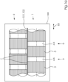
- FIG. 2 shows a preferred embodiment of a folding roller 1 according to the invention of a folding machine 100, which preferably cooperates with another folding roller 2 in a rotational manner.
- the folding rollers are used to produce folded products 101 from processed material 102, e.g., paper.
- Both folding rollers 1 and 2 can have a similar structure. Therefore, the structure of folding roller 1 is described below as an example.
- the folding roller 1 or its roller core can be made of metal, preferably steel, and has (relative to a rotational axis of the folding roller 1) alternating hard segments 3 and soft segments 4 in the axial direction 50.
- the hard segments 3 are formed in the axial direction 50 by alternating hard segments 3a and hard segments 3b.
- the hard segments 3a are preferably made of metal, in particular steel, and can be fixed/non-detachable parts or sections of the folding roller 1.
- the hard segments 3a can be made of hard PU and designed as detachable rings.
- the hard segments 3b are preferably made of hard PU and can be detachable parts or sections of the folding roller or can be accommodated on the folding roller.
- the soft segments 4 are preferably not made of soft PU, as would be expected from the prior art, but rather of hard PU according to the invention.
- a ring 5 is at least partially arranged in a circumferential groove 6 of the folding roller 1 as a sectionally soft segment 4.
- the ring has a Shore A hardness in the range between 60 and 90 Shore, preferably between 60 and 80 Shore and particularly preferably at about 75 Shore.
- the material of the ring is preferably solid, non-cellular or non-foamed.
- the ring 5 can have a recess (on the rear side, i.e., facing the roller core) in its soft section.
- the ring can protrude slightly, e.g., approximately a few hundredths of a millimeter, beyond the surface of the folding roller.
- the ring 5 has a central section 5a (relative to a rotational axis of the folding roller 1 in the axial direction 50) and two axially outer sections 5b (in the axial direction 50).
- the sections 5b are elastically deformable and are each radially movable or displaceable. The latter means that the sections 5b are moved or displaced radially into the groove under pressure, e.g., by pressing between the two rollers 1 and 2, preferably in the order of magnitude of the projection, e.g., a few hundredths of a millimeter.
- the groove 6 has two sections: a central section 6a (in the axial direction 50) and two axially outer sections 6b (in the axial direction 50).
- the groove has a depth 8a and in section 6b a smaller depth 8b.
- the respective depths are measured relative to the surface of the folding roller 1 in the area of the hard segments 3a.
- the circumferential grooves of the folding roller 1 can, for example, be manufactured as recesses in the metal roller.
- the base 11 of the groove 6 is preferably stepped: a central, low step 11a and two adjacent, axially outer, high steps 11b.
- the ring 5 has a thickness 9a that is essentially equal to the depth of the groove 8a or slightly greater (given the projection).
- the ring has a thickness 9b that is less than the depth of the groove 8b, e.g., only 50%, 60%, 70%, 75%, 80%, or 90%.
- the chamber is preferably filled with air.
- the chamber can be filled with a compressible material, e.g., a soft polyurethane.
- the chamber preferably has a rectangular cross-section.
- the chamber 12 enables the respective shoulder 10 to be movable or displaceable in the radial direction 51 within or into the chamber.
- the shoulders 10 of the ring 5 act during operation (i.e., during transport and folding of the material 102) - despite being made of hard PU - similarly to those made of soft PU, enabling the provision of the "grip" function.
- the ring 5 is preferably glued into the groove 6, in particular glued to the bottom 11a or the step 11a of the bottom 11 of the groove. Excess glue can be collected in two circumferential side chambers 13.
- the ring 5 can optionally have a central and circumferential recess 14 (in the axial direction). This recess can also provide mobility or displacement of the hard PU material of the ring 5 in the radial direction 51 in section 15 and thus also provide the "grip" function in section 15.
- Figure 2 shows that the respective segments of the two rollers 1 and 2 are offset from one another by an axial offset 52:
- the central section 5a of the ring 5 of the folding roller 1 lies opposite a hard segment 3a of the folding roller 2 and vice versa.
- the shoulders 10 of the rings 5 of both folding rollers 1 and 2 lie opposite one another. Given a slight projection of the rings 5 over the (preferably metal) surface of the respective folding roller 1 or 2, the shoulders 10 are each moved or displaced slightly into their associated chamber 12. This creates the "grip" function, i.e. the shoulders appear to be made of soft PU.
- no soft PU is used, but (in this embodiment) only hard PU.
- the bottom 11 of the groove 6 can also be designed to be stepless.
- the chambers 12 would then be deeper, provided the thickness 9b of the shoulders 10 of the ring 5 remains the same.
- the thickness 9b can also be selected to be larger so that the chambers are not too deep.
- the projection of the ring 5 in this embodiment can also be selected to be greater than 15/100 mm, or conversely, the ring 5 can be designed to be thinner centrally, i.e., axially between the shoulders, e.g., by turning.
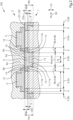
- Figure 3 shows a further preferred embodiment of the invention.
- the structure is comparable to that in Figure 2 shown, however, the chambers 12 here have a substantially wedge-shaped cross-section and the bottom 11 of the groove 6 is not stepped (with the two steps 11a and 11b), but stepless.
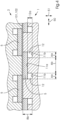
- Figure 4 also shows a further preferred embodiment of the invention. Again, the structure is comparable to that in Figure 2 shown, however, here are the Steps 11a and 11b are designed differently: the depth 8b of the axially outer base 11b is deeper than the depth 8a of the central base 11a. Or, to put it another way: the groove 6 has a central, high step 11a and two adjacent, axially outer, low steps 11b.
- the respective spring rate of the rings 5 shown there, or their axially outer sections/shoulders 10 can be adjusted as follows: selection of the hard PU material; selection of the axial length and radial thickness of the shoulders; and/or selection of the axial length and radial depth of the groove below the shoulder.
- the ring, and in particular its shoulders, are considered as a spring.
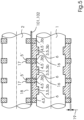
- Figure 5 also shows a further preferred embodiment of the invention.
- the structure is again comparable to that in Figure 2 shown, however, in this embodiment two types of segments 3 and 4 or rings 5 and 5' are used:
- the rings 5 are hard or made of hard PU and the rings 5' are soft or made of soft PU.
- the rings 5 are T-shaped and sit in grooves 6 of the roller 1; the grooves 6 themselves are stepless.
- the rings 5 Between the rings 5, there is a respective distance or gap 16 in the axial direction.
- the rings 5' sit on the surface of the roller 1 and between the rings 5 or in the gaps 16.
- the rings 5' have a radial projection 19 beyond the rings 5 to improve the "grip" function.
- the rings 5 are held in the axial direction by the grooves 6; the rings 5' are held in the axial direction by the rings 5.
- the roller 2 has grooves 17 in which soft rings 5' or rings 5' made of soft PU are received; these are opposite the rings 5' of the roller 1.
- Hard surface segments 18, e.g., made of steel, of the roller 2 are opposite the rings 5 of the roller 1.
- the rings 5' of rollers 1 and 2 interact to provide the "grip" function; the rings 5 and the segments 18 interact to provide the "fold” function.
- the rings 5' of both rollers 1 and 2 can be identical.
- the rings 5' of roller 2 can be slightly wider than the rings 5' of roller 1, so that they overlap with the rings 5 of roller 1 and the "grip" function is improved.
- Figure 6 shows a further preferred embodiment of the invention. Again, the structure is comparable to that in Figure 2 shown, however, the rings 5 each have only one axially outer section 5b formed as a shoulder 10. A ring 5 of the roller 1 or its one shoulder 10 overlaps only with a ring 5 of the roller 2 or its one shoulder 10. The sides of the rings 5 without formed shoulders do not overlap or overlap only insignificantly.
- Figure 7 shows a further preferred embodiment of the invention.
- the two reels 1 and 2 are in Figure 7 shown at a distance from each other, so that the rings 5 and especially their curvature are clearly visible.
- the rollers are positioned against each other and the rings 5 are pressed into the grooves 6, so that the curvatures are not or less pronounced.
- the structure is comparable to that in Figure 2 shown, however, in this embodiment, the axial sections for the "grip" function are not created by shoulders, but by a curvature of the ring 5.
- the ring is designed, for example, such that its cross-section corresponds to a curved or bent rectangle.
- the curvature is preferably selected such that a central section protrudes (radially) relative to axially outer sections.
Landscapes
- Engineering & Computer Science (AREA)
- Mechanical Engineering (AREA)
- Folding Of Thin Sheet-Like Materials, Special Discharging Devices, And Others (AREA)
- Registering, Tensioning, Guiding Webs, And Rollers Therefor (AREA)
Applications Claiming Priority (2)
| Application Number | Priority Date | Filing Date | Title |
|---|---|---|---|
| DE102019211219.6A DE102019211219A1 (de) | 2019-07-29 | 2019-07-29 | Falzwalze mit einer umlaufenden Nut und einem in der umlaufenden Nut angeordneten Ring |
| EP20180439.0A EP3771671B1 (fr) | 2019-07-29 | 2020-06-17 | Rouleau de pliage doté d'une rainure périphérique et d'un anneau disposé dans la rainure périphérique |
Related Parent Applications (2)
| Application Number | Title | Priority Date | Filing Date |
|---|---|---|---|
| EP20180439.0A Division EP3771671B1 (fr) | 2019-07-29 | 2020-06-17 | Rouleau de pliage doté d'une rainure périphérique et d'un anneau disposé dans la rainure périphérique |
| EP20180439.0A Division-Into EP3771671B1 (fr) | 2019-07-29 | 2020-06-17 | Rouleau de pliage doté d'une rainure périphérique et d'un anneau disposé dans la rainure périphérique |
Publications (2)
| Publication Number | Publication Date |
|---|---|
| EP4530238A2 true EP4530238A2 (fr) | 2025-04-02 |
| EP4530238A3 EP4530238A3 (fr) | 2025-06-18 |
Family
ID=71105328
Family Applications (2)
| Application Number | Title | Priority Date | Filing Date |
|---|---|---|---|
| EP20180439.0A Active EP3771671B1 (fr) | 2019-07-29 | 2020-06-17 | Rouleau de pliage doté d'une rainure périphérique et d'un anneau disposé dans la rainure périphérique |
| EP25152444.3A Pending EP4530238A3 (fr) | 2019-07-29 | 2020-06-17 | Rouleau de pliage avec une rainure périphérique et un anneau disposé dans la rainure périphérique |
Family Applications Before (1)
| Application Number | Title | Priority Date | Filing Date |
|---|---|---|---|
| EP20180439.0A Active EP3771671B1 (fr) | 2019-07-29 | 2020-06-17 | Rouleau de pliage doté d'une rainure périphérique et d'un anneau disposé dans la rainure périphérique |
Country Status (4)
| Country | Link |
|---|---|
| EP (2) | EP3771671B1 (fr) |
| CN (1) | CN112297521B (fr) |
| DE (1) | DE102019211219A1 (fr) |
| PT (1) | PT3771671T (fr) |
Citations (7)
| Publication number | Priority date | Publication date | Assignee | Title |
|---|---|---|---|---|
| US3120794A (en) | 1962-02-23 | 1964-02-11 | Polaroid Corp | Apparatus for treating photographic sheet materials with a processing fluid |
| DE2854957A1 (de) | 1978-01-04 | 1979-07-05 | Vittorio Vigano | Faltmaschine zum falten von folien bzw. boegen |
| DE7904616U1 (de) | 1979-02-20 | 1979-07-26 | Stahl Gmbh & Co Maschinenfabrik, 7140 Ludwigsburg | Mit einem mantel ausgeruestete falzwalze |
| DE2905548A1 (de) | 1979-02-14 | 1980-09-04 | Stahl Gmbh & Co Maschf | Falzwalze |
| DE3743642A1 (de) | 1987-12-22 | 1989-07-06 | Binder & Co Masch Oppenweiler | Falzwalze |
| JP2006076676A (ja) | 2004-09-07 | 2006-03-23 | Fuji Xerox Co Ltd | 折り処理装置 |
| EP2960194A1 (fr) | 2014-05-23 | 2015-12-30 | manroland web systems GmbH | Molette de pliage et pièces rapportées en caoutchouc élastique |
Family Cites Families (8)
| Publication number | Priority date | Publication date | Assignee | Title |
|---|---|---|---|---|
| US3240442A (en) * | 1964-02-13 | 1966-03-15 | Beloit Eastern Corp | Bi-textured winder drum |
| US3747917A (en) * | 1971-07-12 | 1973-07-24 | Faltex Falzmaschinenfab Ag | Machine for making concertina folds with reversible rollers and means for reversing same |
| US3796423A (en) * | 1972-09-05 | 1974-03-12 | Rockwell International Corp | Buckle folder fold roller |
| DE2710575C3 (de) * | 1977-03-11 | 1979-09-06 | Sundwiger Eisenhuette Maschinenfabrik Grah & Co, 5870 Hemer | Walzeinrichtung zum Glätten der Streifenkanten eines in eine Vielzahl von Streifen längsgeteilten Bandes |
| DD291308A5 (de) * | 1989-12-29 | 1991-06-27 | Bremer Buchbindereimaschinenbau Gmbh,De | Walze fuer den transport von bogen- und bahnfoermigen material |
| CN202098901U (zh) * | 2010-12-31 | 2012-01-04 | 东莞市金鑫智能机械设备有限公司 | 一种铝箔纸折叠机构 |
| DE102018210836A1 (de) * | 2017-08-08 | 2019-02-14 | Heidelberger Druckmaschinen Ag | Vorrichtung zum Bedrucken und Trocknen von Bedruckstoff |
| CN109704126B (zh) * | 2019-02-26 | 2024-06-18 | 奥美医疗用品股份有限公司 | 一种无纺布折叠切断装置 |
-
2019
- 2019-07-29 DE DE102019211219.6A patent/DE102019211219A1/de active Pending
-
2020
- 2020-06-17 EP EP20180439.0A patent/EP3771671B1/fr active Active
- 2020-06-17 PT PT201804390T patent/PT3771671T/pt unknown
- 2020-06-17 EP EP25152444.3A patent/EP4530238A3/fr active Pending
- 2020-07-29 CN CN202010742261.6A patent/CN112297521B/zh active Active
Patent Citations (7)
| Publication number | Priority date | Publication date | Assignee | Title |
|---|---|---|---|---|
| US3120794A (en) | 1962-02-23 | 1964-02-11 | Polaroid Corp | Apparatus for treating photographic sheet materials with a processing fluid |
| DE2854957A1 (de) | 1978-01-04 | 1979-07-05 | Vittorio Vigano | Faltmaschine zum falten von folien bzw. boegen |
| DE2905548A1 (de) | 1979-02-14 | 1980-09-04 | Stahl Gmbh & Co Maschf | Falzwalze |
| DE7904616U1 (de) | 1979-02-20 | 1979-07-26 | Stahl Gmbh & Co Maschinenfabrik, 7140 Ludwigsburg | Mit einem mantel ausgeruestete falzwalze |
| DE3743642A1 (de) | 1987-12-22 | 1989-07-06 | Binder & Co Masch Oppenweiler | Falzwalze |
| JP2006076676A (ja) | 2004-09-07 | 2006-03-23 | Fuji Xerox Co Ltd | 折り処理装置 |
| EP2960194A1 (fr) | 2014-05-23 | 2015-12-30 | manroland web systems GmbH | Molette de pliage et pièces rapportées en caoutchouc élastique |
Also Published As
| Publication number | Publication date |
|---|---|
| DE102019211219A1 (de) | 2021-02-04 |
| PT3771671T (pt) | 2025-05-09 |
| CN112297521A (zh) | 2021-02-02 |
| EP4530238A3 (fr) | 2025-06-18 |
| CN112297521B (zh) | 2025-09-23 |
| EP3771671A2 (fr) | 2021-02-03 |
| EP3771671A3 (fr) | 2021-06-23 |
| EP3771671B1 (fr) | 2025-04-09 |
Similar Documents
| Publication | Publication Date | Title |
|---|---|---|
| DE2605099C2 (de) | Walzenpresse zur Herstellung eines aus Pulver verpreßten Zwischenproduktes zur Granulaterzeugung | |
| EP3147239B1 (fr) | Courroie dentée avec rouleaux intégrés pour le support | |
| DE69819476T2 (de) | Rotationsstanzwerkzeug | |
| DE69906679T2 (de) | Vorrichtung zum Spannen von um Rollen gewickelten flexiblelen Elementen | |
| DE112016003880T5 (de) | Haltering und Kegelrollenlager | |
| DE2911614A1 (de) | Lineares kreuzroll- bzw. -waelzlager | |
| EP2960194B1 (fr) | Molette de pliage avec pièces rapportées en caoutchouc élastique | |
| DE69913144T2 (de) | Schmirgelvorrichtung | |
| DE60213995T2 (de) | Gummituch mit verriegelungselementen und nicht geradlinigen kanten | |
| DE2655893B2 (de) | Preßwalze mit steuerbarer Durchbiegung zur Behandlung von Materialbahnen | |
| DE3001671A1 (de) | Matrize fuer massivumformung im kalt- oder halbwarmverfahren | |
| DE2538124B2 (de) | Walze für die Druckbehandlung von Warenbahnen | |
| DE3545295C1 (de) | Zugwalzenpaar fuer eine Rotationsdruckmaschine zum Transportieren von Bedruckstoffbahnen | |
| DE2928504C2 (de) | Dichtungsanordnung für Pumpenwellen u.dgl. | |
| EP3771671B1 (fr) | Rouleau de pliage doté d'une rainure périphérique et d'un anneau disposé dans la rainure périphérique | |
| DE2629331A1 (de) | Farbdosiereinrichtung an druckmaschinen | |
| EP0944545B1 (fr) | Dispositif pour la repartition d'un flux de cahiers | |
| DE3743642C2 (fr) | ||
| DE3011669C2 (de) | Preßwalze mit einer Einrichtung zum Korrigieren der Durchbiegung des Walzenmantels | |
| DE102012212699A1 (de) | Maschine zur Herstellung von Wellpappe | |
| DE2315171A1 (de) | Rollenstanze | |
| EP1394079A1 (fr) | Dispositif de transport en particulier pour le transport suspendu de pièces | |
| DE4330545A1 (de) | Rakelvorrichtung | |
| DE60313466T2 (de) | Maschine zur verarbeitung von folien mit quer zu ihrer vorwärtsbewegungsrichtung verlaufenden ausschnitten oder falten | |
| EP1574323B1 (fr) | Elément de rainurage pour rainurer rotativement des produits |
Legal Events
| Date | Code | Title | Description |
|---|---|---|---|
| PUAI | Public reference made under article 153(3) epc to a published international application that has entered the european phase |
Free format text: ORIGINAL CODE: 0009012 |
|
| STAA | Information on the status of an ep patent application or granted ep patent |
Free format text: STATUS: THE APPLICATION HAS BEEN PUBLISHED |
|
| AC | Divisional application: reference to earlier application |
Ref document number: 3771671 Country of ref document: EP Kind code of ref document: P |
|
| AK | Designated contracting states |
Kind code of ref document: A2 Designated state(s): AL AT BE BG CH CY CZ DE DK EE ES FI FR GB GR HR HU IE IS IT LI LT LU LV MC MK MT NL NO PL PT RO RS SE SI SK SM TR |
|
| REG | Reference to a national code |
Ref country code: DE Ref legal event code: R079 Free format text: PREVIOUS MAIN CLASS: B65H0045180000 Ipc: B65H0045240000 |
|
| PUAL | Search report despatched |
Free format text: ORIGINAL CODE: 0009013 |
|
| AK | Designated contracting states |
Kind code of ref document: A3 Designated state(s): AL AT BE BG CH CY CZ DE DK EE ES FI FR GB GR HR HU IE IS IT LI LT LU LV MC MK MT NL NO PL PT RO RS SE SI SK SM TR |
|
| RIC1 | Information provided on ipc code assigned before grant |
Ipc: B65H 45/18 20060101ALI20250509BHEP Ipc: B65H 45/14 20060101ALI20250509BHEP Ipc: B65H 45/12 20060101ALI20250509BHEP Ipc: B65H 45/24 20060101AFI20250509BHEP |
|
| P01 | Opt-out of the competence of the unified patent court (upc) registered |
Free format text: CASE NUMBER: APP_23120/2025 Effective date: 20250515 |