EP4530238A2 - Folding roller with a circumferential groove and a ring arranged in the circumferential groove - Google Patents
Folding roller with a circumferential groove and a ring arranged in the circumferential groove Download PDFInfo
- Publication number
- EP4530238A2 EP4530238A2 EP25152444.3A EP25152444A EP4530238A2 EP 4530238 A2 EP4530238 A2 EP 4530238A2 EP 25152444 A EP25152444 A EP 25152444A EP 4530238 A2 EP4530238 A2 EP 4530238A2
- Authority
- EP
- European Patent Office
- Prior art keywords
- folding roller
- folding
- ring
- rings
- shore
- Prior art date
- Legal status (The legal status is an assumption and is not a legal conclusion. Google has not performed a legal analysis and makes no representation as to the accuracy of the status listed.)
- Pending
Links
Images


Classifications
-
- B—PERFORMING OPERATIONS; TRANSPORTING
- B31—MAKING ARTICLES OF PAPER, CARDBOARD OR MATERIAL WORKED IN A MANNER ANALOGOUS TO PAPER; WORKING PAPER, CARDBOARD OR MATERIAL WORKED IN A MANNER ANALOGOUS TO PAPER
- B31F—MECHANICAL WORKING OR DEFORMATION OF PAPER, CARDBOARD OR MATERIAL WORKED IN A MANNER ANALOGOUS TO PAPER
- B31F1/00—Mechanical deformation without removing material, e.g. in combination with laminating
- B31F1/0003—Shaping by bending, folding, twisting, straightening, flattening or rim-rolling; Shaping by bending, folding or rim-rolling combined with joining; Apparatus therefor
- B31F1/0006—Bending or folding; Folding edges combined with joining; Reinforcing edges during the folding thereof
- B31F1/0009—Bending or folding; Folding edges combined with joining; Reinforcing edges during the folding thereof of plates, sheets or webs
-
- B—PERFORMING OPERATIONS; TRANSPORTING
- B65—CONVEYING; PACKING; STORING; HANDLING THIN OR FILAMENTARY MATERIAL
- B65H—HANDLING THIN OR FILAMENTARY MATERIAL, e.g. SHEETS, WEBS, CABLES
- B65H45/00—Folding thin material
- B65H45/12—Folding articles or webs with application of pressure to define or form crease lines
- B65H45/14—Buckling folders
- B65H45/142—Pocket-type folders
-
- B—PERFORMING OPERATIONS; TRANSPORTING
- B65—CONVEYING; PACKING; STORING; HANDLING THIN OR FILAMENTARY MATERIAL
- B65H—HANDLING THIN OR FILAMENTARY MATERIAL, e.g. SHEETS, WEBS, CABLES
- B65H45/00—Folding thin material
- B65H45/12—Folding articles or webs with application of pressure to define or form crease lines
- B65H45/18—Oscillating or reciprocating blade folders
-
- B—PERFORMING OPERATIONS; TRANSPORTING
- B65—CONVEYING; PACKING; STORING; HANDLING THIN OR FILAMENTARY MATERIAL
- B65H—HANDLING THIN OR FILAMENTARY MATERIAL, e.g. SHEETS, WEBS, CABLES
- B65H2404/00—Parts for transporting or guiding the handled material
- B65H2404/10—Rollers
- B65H2404/13—Details of longitudinal profile
- B65H2404/131—Details of longitudinal profile shape
- B65H2404/1316—Details of longitudinal profile shape stepped or grooved
-
- B—PERFORMING OPERATIONS; TRANSPORTING
- B65—CONVEYING; PACKING; STORING; HANDLING THIN OR FILAMENTARY MATERIAL
- B65H—HANDLING THIN OR FILAMENTARY MATERIAL, e.g. SHEETS, WEBS, CABLES
- B65H2404/00—Parts for transporting or guiding the handled material
- B65H2404/10—Rollers
- B65H2404/13—Details of longitudinal profile
- B65H2404/132—Details of longitudinal profile arrangement of segments along axis
-
- B—PERFORMING OPERATIONS; TRANSPORTING
- B65—CONVEYING; PACKING; STORING; HANDLING THIN OR FILAMENTARY MATERIAL
- B65H—HANDLING THIN OR FILAMENTARY MATERIAL, e.g. SHEETS, WEBS, CABLES
- B65H2404/00—Parts for transporting or guiding the handled material
- B65H2404/10—Rollers
- B65H2404/18—Rollers composed of several layers
- B65H2404/181—Rollers composed of several layers with cavities or projections at least at one layer
-
- B—PERFORMING OPERATIONS; TRANSPORTING
- B65—CONVEYING; PACKING; STORING; HANDLING THIN OR FILAMENTARY MATERIAL
- B65H—HANDLING THIN OR FILAMENTARY MATERIAL, e.g. SHEETS, WEBS, CABLES
- B65H2404/00—Parts for transporting or guiding the handled material
- B65H2404/10—Rollers
- B65H2404/18—Rollers composed of several layers
- B65H2404/187—Rollers composed of several layers with wear resistance
Definitions
- the invention relates to a folding roller according to claim 1 and further objects according to claims 10 and 14.
- the invention lies in the technical field of the graphic industry and in particular in the area of folding printing materials, such as paper.
- the industrial folding of sheet-shaped printing materials is carried out using folding machines, which typically comprise a sheet feeder and at least one folding unit with a plurality of folding rollers.
- the folding units of the machine can each comprise buckle plate folding units and/or knife folding units.
- the sheets are folded between two rotating folding rollers positioned opposite each other.
- the peripheral surfaces of the folding rollers can be made of metal.
- the folding rollers can have grooves in which elastomer rings are accommodated.
- the DE7904616U1 discloses a folding roller equipped with a friction jacket and rings made of elastically deformable material.
- the rings can be grooved on their outer surface.
- DE2854957A1 and the DE3743642A1 reveal similar things.
- the EP2960194A1 discloses a folding roller with grooves for guiding folding belts. Rubber-elastic or compressible inserts or rings are arranged in the grooves below the folding belts.
- the conveyor belts can have a projection of approximately 0.05-0.5 mm above the outer surface of the folding roller. The inserts therefore do not have such a projection beyond the outer surface.
- the DE2905548 discloses a steel folding roller. Ring grooves are incorporated into the roller's casing. Prefabricated rings made of elastically deformable (“rubber-elastic") plastic are inserted into these grooves. The material of the rings has a hardness between 60 and 100 Shore A units. Accordingly, the roller features hard steel segments or hard plastic segments on its surface.
- the JP2006076676A discloses a pair of folding rollers, each folding roller having, in its axial direction, alternating rubber rings having a hardness of about 30° and a hardness of 60° or more.
- the US3120794 discloses a roller other than a folding roller with a sealing ring.
- the sealing ring may have a shoulder.
- a folding roller according to the invention with at least one circumferential groove and a ring arranged at least partially in the circumferential groove, comprising a material with a Shore A hardness in the range between 50 and 95 Shore, is characterized in that the ring projects slightly beyond the surface of the folding roller and comprises at least one elastic section which is at least partially radially deformable with respect to the folding roller, the groove and/or a bottom of the groove.
- the material used according to the invention with a Shore A hardness in the range between 50 and 95 Shore is preferably an elastic material, more preferably an elastomer and in particular a polyurethane (PU), more particularly a so-called hard PU, e.g. a polyester urethane rubber.
- PU polyurethane
- a "hard” material is defined as a material with a Shore A hardness between 50 and 95 Shore, in particular between 60 and 80 Shore, or especially 75 +/- 5 Shore.
- the material is not foamed or only slightly foamed and is therefore essentially solid.
- the material can be, for example, Vulkollan® .
- Hard PU as a material for folding roller rings offers the advantage of being resistant to ink buildup and having a longer service life than, for example, rubber. It also offers "greater grip" than rubber, meaning it offers better substrate transport properties.
- the material used according to the invention with a Shore A hardness in the range below 50 Shore is preferably an elastic material, more preferably an elastomer and in particular a polyurethane (PU), more particularly a so-called soft PU, e.g. a polyester urethane rubber.
- PU polyurethane
- a “soft” (or “soft”) material is defined as a material with a Shore A hardness of less than 50.
- the material is preferably foamed and therefore essentially cellular or porous and therefore compressible.
- Soft PU is particularly advantageous for transporting smooth paper.
- polyethylene or polypropylene can be used as a material, preferably as a hard or soft material.
- the Shore hardness or Shore A hardness is a material characteristic for elastic materials, elastomers and/or plastics and can be determined in accordance with the standards DIN EN ISO 868, DIN ISO 7619-1 and ASTM D2240-00.
- At least partially radial means, for example, that in addition to a radial component, an axial component of mobility, positionability, or deformability can also be present.
- the folding roller according to the invention advantageously enables printing materials to be transported and folded precisely and smoothly.
- the rings are preferably made of hard PU. Thanks to the sections according to the invention (hereinafter also referred to as "shoulders"), the relatively hard rings advantageously behave, at least in sections, like soft PU rings.
- the roller is simple and cost-effective to manufacture and maintain.
- the folding roller advantageously preferably has only rings made of hard PU and no rings made of soft PU.
- An alternative, further folding roller according to the invention is a folding roller with circumferential grooves and rings for the transport and folding of sheets of printing material, wherein either the grooves each have a varying depth in the axial direction and/or the rings each have a varying thickness in the axial direction.
- thickness varying in the axial direction means, for example, that the thickness of the ring (depending on the axial position or as a function thereof) is not constant or that the ring has substantially different thicknesses at at least two axial positions.
- the thickness of the ring can be The thickness is preferably measured in the radial direction or is a radial thickness.
- roller or roller rings are low-wear.
- a preferred development of the invention can be characterized in that the section is a decentralized section, i.e. is arranged decentrally or off-center with respect to the ring in the axial direction.
- a preferred development of the invention can be characterized in that the section is an outer section, i.e. is arranged on the outside with respect to the ring in the axial direction, preferably on the lateral edge of the ring.
- a preferred development of the invention can be characterized in that the chamber has a height measured in the radial direction which is constant in the axial direction or that the chamber has a rectangular cross-section.
- a preferred development of the invention can be characterized in that the chamber has a height measured in the radial direction that is variable in the axial direction, or in that the chamber has a wedge-shaped cross-section.
- a preferred embodiment of the invention can be characterized in that the Shore A hardness is in the range between 60 and 80 Shore or 75 +/- 5 Shore and/or that the material is an elastic material, an elastomer, or rigid polyurethane, wherein the material is solid, non-cellular, or non-foamed.
- a preferred development of the invention can be characterized in that the ring projects a few hundredths of a millimeter above the surface of the folding roller.
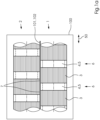
- Figure 1A shows a folding roller 1 according to the prior art, which interacts with another folding roller 2. Both rollers are preferably arranged in a folding machine 100 and serve to produce folded products 101 from material 102 to be processed.
- the folding roller 1 has alternating hard segments 3 and soft segments 4 in the axial direction (direction 50 in the figure).
- the hard segments can be made of metal, in particular steel, and can be part or sections of the folding roller. These segments can have axial ribbing on their surface.
- the soft segments can be made of a soft PU and be designed as rings 5', which are received on the roller. The rings can be arranged in circumferential grooves 6 of the folding roller. The same applies to the folding roller 2.
- the folding roller 1 has, with respect to its surface, a larger proportion of hard segments 3 and a smaller proportion of soft segments 4, e.g., in a ratio of approximately 3:2 or approximately 4:3.
- the hard segments of one roller overlap in respective overlap areas 7 with hard segments of the opposite roller.
- the hard segments 3 have the function of creating a good fold in the material 102 to be processed, e.g., paper (hereinafter referred to as the "Fold” function), while the soft segments 4 have the function of ensuring good transport of the material (hereinafter referred to as the "Grip” function).
- the folding rollers according to the invention described below also have these two functions.
- a disadvantage of this prior art solution is that clearly visible and therefore disturbing lines can arise in the material 102 to be processed in the respective overlapping areas 7, which reduce the quality of the folded product.
- a further disadvantage is the wear of the roller surface.
- the folding roller 1 has a higher proportion of soft segments 4 and a lower proportion of hard segments 3 on its surface, e.g., in a ratio of approximately 2:5 or 3:5 or 4:5.
- the soft segments 4 of one roller overlap in respective overlap areas 7 with soft segments of the opposite roller.
- the overlap can, e.g., be approximately a few millimeters. Accordingly, in comparison to the Figure 1A not an overlap of hard segments, but an overlap of soft segments.
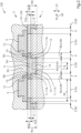
- FIG. 2 shows a preferred embodiment of a folding roller 1 according to the invention of a folding machine 100, which preferably cooperates with another folding roller 2 in a rotational manner.
- the folding rollers are used to produce folded products 101 from processed material 102, e.g., paper.
- Both folding rollers 1 and 2 can have a similar structure. Therefore, the structure of folding roller 1 is described below as an example.
- the folding roller 1 or its roller core can be made of metal, preferably steel, and has (relative to a rotational axis of the folding roller 1) alternating hard segments 3 and soft segments 4 in the axial direction 50.
- the hard segments 3 are formed in the axial direction 50 by alternating hard segments 3a and hard segments 3b.
- the hard segments 3a are preferably made of metal, in particular steel, and can be fixed/non-detachable parts or sections of the folding roller 1.
- the hard segments 3a can be made of hard PU and designed as detachable rings.
- the hard segments 3b are preferably made of hard PU and can be detachable parts or sections of the folding roller or can be accommodated on the folding roller.
- the soft segments 4 are preferably not made of soft PU, as would be expected from the prior art, but rather of hard PU according to the invention.
- a ring 5 is at least partially arranged in a circumferential groove 6 of the folding roller 1 as a sectionally soft segment 4.
- the ring has a Shore A hardness in the range between 60 and 90 Shore, preferably between 60 and 80 Shore and particularly preferably at about 75 Shore.
- the material of the ring is preferably solid, non-cellular or non-foamed.
- the ring 5 can have a recess (on the rear side, i.e., facing the roller core) in its soft section.
- the ring can protrude slightly, e.g., approximately a few hundredths of a millimeter, beyond the surface of the folding roller.
- the ring 5 has a central section 5a (relative to a rotational axis of the folding roller 1 in the axial direction 50) and two axially outer sections 5b (in the axial direction 50).
- the sections 5b are elastically deformable and are each radially movable or displaceable. The latter means that the sections 5b are moved or displaced radially into the groove under pressure, e.g., by pressing between the two rollers 1 and 2, preferably in the order of magnitude of the projection, e.g., a few hundredths of a millimeter.
- the groove 6 has two sections: a central section 6a (in the axial direction 50) and two axially outer sections 6b (in the axial direction 50).
- the groove has a depth 8a and in section 6b a smaller depth 8b.
- the respective depths are measured relative to the surface of the folding roller 1 in the area of the hard segments 3a.
- the circumferential grooves of the folding roller 1 can, for example, be manufactured as recesses in the metal roller.
- the base 11 of the groove 6 is preferably stepped: a central, low step 11a and two adjacent, axially outer, high steps 11b.
- the ring 5 has a thickness 9a that is essentially equal to the depth of the groove 8a or slightly greater (given the projection).
- the ring has a thickness 9b that is less than the depth of the groove 8b, e.g., only 50%, 60%, 70%, 75%, 80%, or 90%.
- the chamber is preferably filled with air.
- the chamber can be filled with a compressible material, e.g., a soft polyurethane.
- the chamber preferably has a rectangular cross-section.
- the chamber 12 enables the respective shoulder 10 to be movable or displaceable in the radial direction 51 within or into the chamber.
- the shoulders 10 of the ring 5 act during operation (i.e., during transport and folding of the material 102) - despite being made of hard PU - similarly to those made of soft PU, enabling the provision of the "grip" function.
- the ring 5 is preferably glued into the groove 6, in particular glued to the bottom 11a or the step 11a of the bottom 11 of the groove. Excess glue can be collected in two circumferential side chambers 13.
- the ring 5 can optionally have a central and circumferential recess 14 (in the axial direction). This recess can also provide mobility or displacement of the hard PU material of the ring 5 in the radial direction 51 in section 15 and thus also provide the "grip" function in section 15.
- Figure 2 shows that the respective segments of the two rollers 1 and 2 are offset from one another by an axial offset 52:
- the central section 5a of the ring 5 of the folding roller 1 lies opposite a hard segment 3a of the folding roller 2 and vice versa.
- the shoulders 10 of the rings 5 of both folding rollers 1 and 2 lie opposite one another. Given a slight projection of the rings 5 over the (preferably metal) surface of the respective folding roller 1 or 2, the shoulders 10 are each moved or displaced slightly into their associated chamber 12. This creates the "grip" function, i.e. the shoulders appear to be made of soft PU.
- no soft PU is used, but (in this embodiment) only hard PU.
- the bottom 11 of the groove 6 can also be designed to be stepless.
- the chambers 12 would then be deeper, provided the thickness 9b of the shoulders 10 of the ring 5 remains the same.
- the thickness 9b can also be selected to be larger so that the chambers are not too deep.
- the projection of the ring 5 in this embodiment can also be selected to be greater than 15/100 mm, or conversely, the ring 5 can be designed to be thinner centrally, i.e., axially between the shoulders, e.g., by turning.
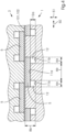
- Figure 3 shows a further preferred embodiment of the invention.
- the structure is comparable to that in Figure 2 shown, however, the chambers 12 here have a substantially wedge-shaped cross-section and the bottom 11 of the groove 6 is not stepped (with the two steps 11a and 11b), but stepless.
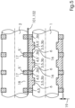
- Figure 4 also shows a further preferred embodiment of the invention. Again, the structure is comparable to that in Figure 2 shown, however, here are the Steps 11a and 11b are designed differently: the depth 8b of the axially outer base 11b is deeper than the depth 8a of the central base 11a. Or, to put it another way: the groove 6 has a central, high step 11a and two adjacent, axially outer, low steps 11b.
- the respective spring rate of the rings 5 shown there, or their axially outer sections/shoulders 10 can be adjusted as follows: selection of the hard PU material; selection of the axial length and radial thickness of the shoulders; and/or selection of the axial length and radial depth of the groove below the shoulder.
- the ring, and in particular its shoulders, are considered as a spring.
- Figure 5 also shows a further preferred embodiment of the invention.
- the structure is again comparable to that in Figure 2 shown, however, in this embodiment two types of segments 3 and 4 or rings 5 and 5' are used:
- the rings 5 are hard or made of hard PU and the rings 5' are soft or made of soft PU.
- the rings 5 are T-shaped and sit in grooves 6 of the roller 1; the grooves 6 themselves are stepless.
- the rings 5 Between the rings 5, there is a respective distance or gap 16 in the axial direction.
- the rings 5' sit on the surface of the roller 1 and between the rings 5 or in the gaps 16.
- the rings 5' have a radial projection 19 beyond the rings 5 to improve the "grip" function.
- the rings 5 are held in the axial direction by the grooves 6; the rings 5' are held in the axial direction by the rings 5.
- the roller 2 has grooves 17 in which soft rings 5' or rings 5' made of soft PU are received; these are opposite the rings 5' of the roller 1.
- Hard surface segments 18, e.g., made of steel, of the roller 2 are opposite the rings 5 of the roller 1.
- the rings 5' of rollers 1 and 2 interact to provide the "grip" function; the rings 5 and the segments 18 interact to provide the "fold” function.
- the rings 5' of both rollers 1 and 2 can be identical.
- the rings 5' of roller 2 can be slightly wider than the rings 5' of roller 1, so that they overlap with the rings 5 of roller 1 and the "grip" function is improved.
- Figure 6 shows a further preferred embodiment of the invention. Again, the structure is comparable to that in Figure 2 shown, however, the rings 5 each have only one axially outer section 5b formed as a shoulder 10. A ring 5 of the roller 1 or its one shoulder 10 overlaps only with a ring 5 of the roller 2 or its one shoulder 10. The sides of the rings 5 without formed shoulders do not overlap or overlap only insignificantly.
- Figure 7 shows a further preferred embodiment of the invention.
- the two reels 1 and 2 are in Figure 7 shown at a distance from each other, so that the rings 5 and especially their curvature are clearly visible.
- the rollers are positioned against each other and the rings 5 are pressed into the grooves 6, so that the curvatures are not or less pronounced.
- the structure is comparable to that in Figure 2 shown, however, in this embodiment, the axial sections for the "grip" function are not created by shoulders, but by a curvature of the ring 5.
- the ring is designed, for example, such that its cross-section corresponds to a curved or bent rectangle.
- the curvature is preferably selected such that a central section protrudes (radially) relative to axially outer sections.
Landscapes
- Engineering & Computer Science (AREA)
- Mechanical Engineering (AREA)
- Folding Of Thin Sheet-Like Materials, Special Discharging Devices, And Others (AREA)
- Registering, Tensioning, Guiding Webs, And Rollers Therefor (AREA)
Abstract
Eine erfindungsgemäße Falzwalze mit wenigstens einer umlaufenden Nut (6) und einem zumindest teilweise in der umlaufenden Nut angeordneten Ring (5), umfassend ein Material mit einer Shore-A-Härte im Bereich zwischen 50 und 95 Shore, zeichnet sich dadurch aus, dass der Ring (5) geringfügig über die Oberfläche der Falzwalze (1, 2) übersteht und wenigstens einen, bevorzugt axial außenliegenden, elastischen Abschnitt (10), bevorzugt eine Schulter (10), umfasst, welcher bezüglich der Falzwalze (1), der Nut (6) und/oder einem Boden (11) der Nut jeweils wenigstens anteilig radial verformbar ist. Die Erfindung ermöglicht es in vorteilhafter Weise, Bedruckstoffe präzise und störungsfrei sowohl zu transportieren als auch zugleich zu falzen.A folding roller according to the invention with at least one circumferential groove (6) and a ring (5) arranged at least partially in the circumferential groove, comprising a material with a Shore A hardness in the range between 50 and 95 Shore, is characterized in that the ring (5) projects slightly beyond the surface of the folding roller (1, 2) and comprises at least one, preferably axially outer, elastic section (10), preferably a shoulder (10), which is at least partially radially deformable with respect to the folding roller (1), the groove (6) and/or a base (11) of the groove. The invention advantageously makes it possible to both transport and simultaneously fold printing materials precisely and smoothly.
Description
Die Erfindung betrifft eine Falzwalze nach Anspruch1 und weitere Gegenstände nach den Ansprüchen 10 und 14.The invention relates to a folding roller according to claim 1 and further objects according to
Die Erfindung liegt auf dem technischen Gebiet der grafischen Industrie und dort insbesondere im Bereich des Falzens von Bedruckstoffen, wie z.B. Papieren.The invention lies in the technical field of the graphic industry and in particular in the area of folding printing materials, such as paper.
Das industrielle Falzen von bogenförmigem Bedruckstoff erfolgt unter Einsatz von Falzmaschinen, welche in der Regel einen Anleger für die Bogen und wenigstens ein Falzaggregat mit einer Mehrzahl von Falzwalzen umfassen. Die Falzaggregate der Maschine können jeweils Taschenfalzwerke und/oder Schwertfalzwerke umfassen.The industrial folding of sheet-shaped printing materials is carried out using folding machines, which typically comprise a sheet feeder and at least one folding unit with a plurality of folding rollers. The folding units of the machine can each comprise buckle plate folding units and/or knife folding units.
Das Falzen der Bogen erfolgt zwischen zwei gegeneinander angestellten, rotierenden Falzwalzen. Die Umfangsflächen der Falzwalzen können aus Metall gebildet sein. Die Falzwalzen können Nuten aufweisen, in denen Ringe aus einem Elastomer aufgenommen sind.The sheets are folded between two rotating folding rollers positioned opposite each other. The peripheral surfaces of the folding rollers can be made of metal. The folding rollers can have grooves in which elastomer rings are accommodated.
Die
Zwei bekannte, aber nachteilige Lösungen des Standes der Technik sind detailliert in den
Die
Die
Die
Die
Es ist daher eine Aufgabe der Erfindung, Verbesserungen gegenüber dem Stand der Technik zu schaffen, welche es insbesondere ermöglichen, Bedruckstoffe präzise und störungsfrei sowohl zu transportieren als auch zugleich zu falzen.It is therefore an object of the invention to provide improvements over the prior art which, in particular, make it possible to both transport and simultaneously fold printing materials precisely and smoothly.
Diese Aufgaben werden erfindungsgemäß durch eine Falzwalze mit den Merkmalen des Anspruchs 1 und durch weitere Gegenstände nach den Ansprüchen 10 und 14 gelöst. Vorteilhafte und daher bevorzugte Weiterbildungen der Erfindung ergeben sich aus den Unteransprüchen sowie aus der Beschreibung und den Zeichnungen.These objects are achieved according to the invention by a folding roller having the features of claim 1 and by further objects according to
Eine erfindungsgemäße Falzwalze mit wenigstens einer umlaufenden Nut und einem zumindest teilweise in der umlaufenden Nut angeordneten Ring, umfassend ein Material mit einer Shore-A-Härte im Bereich zwischen 50 und 95 Shore, zeichnet sich dadurch aus, dass der Ring geringfügig über die Oberfläche der Falzwalze übersteht und wenigstens einen elastischen Abschnitt umfasst, welcher bezüglich der Falzwalze, der Nut und/oder einem Boden der Nut jeweils wenigstens anteilig radial verformbar ist.A folding roller according to the invention with at least one circumferential groove and a ring arranged at least partially in the circumferential groove, comprising a material with a Shore A hardness in the range between 50 and 95 Shore, is characterized in that the ring projects slightly beyond the surface of the folding roller and comprises at least one elastic section which is at least partially radially deformable with respect to the folding roller, the groove and/or a bottom of the groove.
Das erfindungsgemäß verwendete Material mit einer Shore-A-Härte im Bereich zwischen 50 und 95 Shore ist bevorzugt ein elastisches Material, weiter bevorzugt ein Elastomer und insbesondere ein Polyurethan (PU), weiter insbesondere ein so genanntes Hart-PU, z.B. ein Polyester-Urethan-Kautschuk.The material used according to the invention with a Shore A hardness in the range between 50 and 95 Shore is preferably an elastic material, more preferably an elastomer and in particular a polyurethane (PU), more particularly a so-called hard PU, e.g. a polyester urethane rubber.
Als "hartes" Material, insbesondere Hart-PU wird in dieser Anmeldung verstanden: Ein Material mit einer Shore-A-Härte zwischen 50 und 95 Shore, insbesondere zwischen 60 und 80 Shore oder insbesondere 75 +/- 5 Shore. Das Material ist nicht oder nur unwesentlich aufgeschäumt und daher im Wesentlichen massiv. Das Material kann z.B. Vulkollan® sein. Hart-PU als Material für Falzwalzen-Ringe bietet den Vorteil, dass es resistent gegen Farbaufbau ist und eine längere Lebensdauer als z.B. Gummi hat und "griffiger" als Gummi ist, d.h. bessere Bedruckstoff-Transporteigenschaften bietet.In this application, a "hard" material, particularly hard PU, is defined as a material with a Shore A hardness between 50 and 95 Shore, in particular between 60 and 80 Shore, or especially 75 +/- 5 Shore. The material is not foamed or only slightly foamed and is therefore essentially solid. The material can be, for example, Vulkollan® . Hard PU as a material for folding roller rings offers the advantage of being resistant to ink buildup and having a longer service life than, for example, rubber. It also offers "greater grip" than rubber, meaning it offers better substrate transport properties.
Das erfindungsgemäß verwendete Material mit einer Shore-A-Härte im Bereich unterhalb von 50 Shore ist bevorzugt ein elastisches Material, weiter bevorzugt ein Elastomer und insbesondere ein Polyurethan (PU), weiter insbesondere ein so genanntes Soft-PU, z.B. ein Polyester-Urethan-Kautschuk.The material used according to the invention with a Shore A hardness in the range below 50 Shore is preferably an elastic material, more preferably an elastomer and in particular a polyurethane (PU), more particularly a so-called soft PU, e.g. a polyester urethane rubber.
Als "weiches" (oder "softes") Material, insbesondere Soft-PU wird in dieser Anmeldung verstanden: Ein Material mit einer Shore-A-Härte von weniger als 50 Shore. Das Material ist bevorzugt aufgeschäumt und daher im Wesentlichen zellig bzw. porös und infolge kompressibel. Soft-PU ist insbesondere beim Transport von glatten Papieren von Vorteil.In this application, a "soft" (or "soft") material, especially soft PU, is defined as a material with a Shore A hardness of less than 50. The material is preferably foamed and therefore essentially cellular or porous and therefore compressible. Soft PU is particularly advantageous for transporting smooth paper.
Alternativ zu einem Polyurethan (Hart-PU oder Soft-PU) kann Polyethylen oder Polypropylen als Material verwendet werden, bevorzugt jeweils als Hart- oder Soft-Material.As an alternative to polyurethane (hard PU or soft PU), polyethylene or polypropylene can be used as a material, preferably as a hard or soft material.
Die Shore-Härte oder Shore-A-Härte ist ein Werkstoffkennwert für elastische Materialien, Elastomere und/oder Kunststoffe und kann in Anlehnung an die Normen DIN EN ISO 868, DIN ISO 7619-1 und ASTM D2240-00 bestimmt werden.The Shore hardness or Shore A hardness is a material characteristic for elastic materials, elastomers and/or plastics and can be determined in accordance with the standards DIN EN ISO 868, DIN ISO 7619-1 and ASTM D2240-00.
Der Begriff "wenigstens anteilig radial" meint beispielsweise, dass neben einer radialen Komponente auch eine axiale Komponente der Beweglichkeit oder der Positionierbarkeit oder der Verformbarkeit vorhanden sein kann. Bevorzugt wird eine im Vergleich zur radialen Komponente unwesentliche axiale Komponente, z.B. kleiner 10% oder kleiner 5% oder kleiner 1%.The term "at least partially radial" means, for example, that in addition to a radial component, an axial component of mobility, positionability, or deformability can also be present. An axial component that is insignificant compared to the radial component, e.g., less than 10%, less than 5%, or less than 1%, is preferred.
Die erfindungsgemäße Falzwalze ermöglicht in vorteilhafter Weise, Bedruckstoffe präzise und störungsfrei sowohl zu transportieren als auch zugleich zu falzen. Die Ringe sind bevorzugt aus Hart-PU gefertigt. Durch die erfindungsgemäßen Abschnitte (im Folgenden auch "Schultern" genannt) verhalten sich die relativ harten Ringe in vorteilhafter Weise dennoch zumindest abschnittsweise wie Soft-PU-Ringe. Die Walze ist einfach und kostengünstig in der Herstellung und Wartung. Dabei weist die Falzwalze in vorteilhafter Weise bevorzugt nur Ringe aus Hart-PU auf und keine Ringe aus Soft-PU auf.The folding roller according to the invention advantageously enables printing materials to be transported and folded precisely and smoothly. The rings are preferably made of hard PU. Thanks to the sections according to the invention (hereinafter also referred to as "shoulders"), the relatively hard rings advantageously behave, at least in sections, like soft PU rings. The roller is simple and cost-effective to manufacture and maintain. The folding roller advantageously preferably has only rings made of hard PU and no rings made of soft PU.
Eine alternative, weitere erfindungsgemäße Falzwalze ist eine Falzwalze mit umlaufenden Nuten und Ringen für den Transport und das Falzen von Bogen aus Bedruckstoff, wobei entweder die Nuten jeweils in axialer Richtung eine sich ändernde Tiefe aufweisen und/oder die Ringe jeweils in axialer Richtung eine sich ändernde Dicke aufweisen.An alternative, further folding roller according to the invention is a folding roller with circumferential grooves and rings for the transport and folding of sheets of printing material, wherein either the grooves each have a varying depth in the axial direction and/or the rings each have a varying thickness in the axial direction.
Der Begriff "in axialer Richtung sich ändernde Dicke" meint beispielsweise, dass die Dicke des Rings (in Abhängigkeit der axialen Position oder als deren Funktion) nicht konstant ist bzw. dass der Ring an wenigstens zwei axialen Positionen zueinander wesentlich verschiedene Dicken aufweist. Beispielsweise kann die Dicke des Rings eine Stufe aufweisen. Die Dicke wird bevorzugt in radialer Richtung gemessen bzw. ist eine radiale Dicke.The term "thickness varying in the axial direction" means, for example, that the thickness of the ring (depending on the axial position or as a function thereof) is not constant or that the ring has substantially different thicknesses at at least two axial positions. For example, the thickness of the ring can be The thickness is preferably measured in the radial direction or is a radial thickness.
Auch die alternative, weitere erfindungsgemäße Falzwalze ermöglicht in vorteilhafter Weise, Bedruckstoffe präzise und störungsfrei sowohl zu transportieren als auch zugleich zu falzen. Zudem ist die Walze oder sind die Ringe der Walze verschleißarm.The alternative, further folding roller according to the invention also advantageously enables printing materials to be transported and folded precisely and smoothly. Furthermore, the roller or roller rings are low-wear.
Alle erfindungsgemäßen Falzwalzen bieten aufgrund ihres Aufbaus jeweils eine hervorragende Kombination von Bogen-Führungseigenschaft und Falzeigenschaft.Due to their design, all folding rollers according to the invention offer an excellent combination of sheet guiding properties and folding properties.
Eine bevorzugte Weiterbildung der Erfindung kann sich dadurch auszeichnen, dass der Abschnitt ein dezentraler Abschnitt ist, d.h. bezüglich des Rings in axialer Richtung dezentral oder außermittig angeordnet ist.A preferred development of the invention can be characterized in that the section is a decentralized section, i.e. is arranged decentrally or off-center with respect to the ring in the axial direction.
Eine bevorzugte Weiterbildung der Erfindung kann sich dadurch auszeichnen, dass der Abschnitt ein äußerer Abschnitt ist, d.h. bezüglich des Rings in axialer Richtung außenliegend, bevorzugt am seitlichen Rand des Rings, angeordnet ist.A preferred development of the invention can be characterized in that the section is an outer section, i.e. is arranged on the outside with respect to the ring in the axial direction, preferably on the lateral edge of the ring.
Eine bevorzugte Weiterbildung der Erfindung kann sich dadurch auszeichnen, dass zwischen den Abschnitten und dem Boden der jeweiligen Nut eine jeweilige umlaufende Kammer ausgebildet ist und dass die Kammer mit Luft oder mit einem von Luft verschiedenen, kompressiblen Material gefüllt ist. Die Kammern ermöglichen in vorteilhafter und einfacher Weise die radiale Beweglichkeit und/oder Positionierbarkeit der Abschnitte bzw. Schultern. Durch die Kammern bzw. die korrespondierenden Hohlräume wird bevorzugt eine ausreichende Hohllage der Schultern und dadurch wiederum deren Beweglichkeit/Positionierbarkeit erreicht.A preferred development of the invention can be characterized in that a respective circumferential chamber is formed between the sections and the bottom of the respective groove, and in that the chamber is filled with air or with a compressible material other than air. The chambers advantageously and easily enable the radial mobility and/or positioning of the sections or shoulders. The chambers or the corresponding cavities preferably achieve a sufficiently hollow position of the shoulders and thus, in turn, their mobility/positionability.
Eine bevorzugte Weiterbildung der Erfindung kann sich dadurch auszeichnen, dass die Kammer eine in radialer Richtung gemessene Höhe hat, welche in axialer Richtung konstant ist oder dass die Kammer einen rechteckigen Querschnitt besitzt. Durch die Wahl der Länge und der Höhe des Rechtecks kann die Federrate des Abschnitts bzw. der Schulter präzise eingestellt werden.A preferred development of the invention can be characterized in that the chamber has a height measured in the radial direction which is constant in the axial direction or that the chamber has a rectangular cross-section. By choosing The length and height of the rectangle allow the spring rate of the section or shoulder to be precisely adjusted.
Eine bevorzugte Weiterbildung der Erfindung kann sich dadurch auszeichnen, dass die Kammer eine in radialer Richtung gemessene Höhe hat, welche in axialer Richtung variabel ist oder dass die Kammer einen keilförmigen Querschnitt besitzt. Durch die Wahl des keilförmigen Querschnitts, z.B. durch Wahl eines entsprechenden Winkels des Keils, kann die Federrate des Abschnitts bzw. der Schulter präzise eingestellt werden.A preferred development of the invention can be characterized in that the chamber has a height measured in the radial direction that is variable in the axial direction, or in that the chamber has a wedge-shaped cross-section. By selecting the wedge-shaped cross-section, e.g., by selecting a corresponding wedge angle, the spring rate of the section or shoulder can be precisely adjusted.
Eine bevorzugte Weiterbildung der Erfindung kann sich dadurch auszeichnen, dass die Shore-A-Härte im Bereich zwischen 60 und 80 Shore oder bei 75 +/- 5 Shore liegt und/oder dass das Material ein elastisches Material oder ein Elastomer oder Hart-Polyurethan ist, wobei das Material massiv oder nicht-zellig oder nicht-aufgeschäumt ist. Durch die Wahl des Materials und der Shore-A-Härte kann die Federrate des Abschnitts bzw. der Schulter präzise eingestellt werden.A preferred embodiment of the invention can be characterized in that the Shore A hardness is in the range between 60 and 80 Shore or 75 +/- 5 Shore and/or that the material is an elastic material, an elastomer, or rigid polyurethane, wherein the material is solid, non-cellular, or non-foamed. By selecting the material and the Shore A hardness, the spring rate of the section or shoulder can be precisely adjusted.
Eine bevorzugte Weiterbildung der Erfindung kann sich dadurch auszeichnen, dass der Ring einige hundertstel Millimeter über die Oberfläche der Falzwalze übersteht.A preferred development of the invention can be characterized in that the ring projects a few hundredths of a millimeter above the surface of the folding roller.
Die Merkmale der Erfindung, der Weiterbildungen der Erfindung und der Ausführungsbeispiele zur Erfindung stellen auch in beliebiger Kombination miteinander vorteilhafte Weiterbildungen der Erfindung dar. Weiterbildungen der Erfindung können zudem die - im obigen Abschnitt "Technisches Gebiet der Erfindung" offenbarten - Einzelmerkmale oder Merkmalskombinationen aufweisen.The features of the invention, the developments of the invention and the exemplary embodiments of the invention also represent advantageous developments of the invention in any combination with one another. Further developments of the invention can also have the individual features or combinations of features disclosed in the above section "Technical field of the invention".
Die erfindungsgemäßen Falzwalzen und deren bevorzugte Weiterbildungen werden nachfolgend unter Bezug auf die Zeichnungen anhand bevorzugter Ausführungsbeispiele näher beschrieben. Einander entsprechende Merkmale sind in den Figuren mit denselben Bezugszeichen versehen.The folding rollers according to the invention and their preferred developments are described in more detail below with reference to the drawings using preferred embodiments. Corresponding features are provided with the same reference numerals in the figures.
Die Zeichnungen zeigen:
- Figuren 1A und 1B
- Falzwalzen nach dem Stand der Technik;
Figur 2- erfindungsgemäße Falzwalzen;
Figur 3- erfindungsgemäße Falzwalzen;
Figur 4- erfindungsgemäße Falzwalzen;
Figur 5- erfindungsgemäße Falzwalzen;
Figur 6- erfindungsgemäße Falzwalzen; und
Figur 7- erfindungsgemäße Falzwalzen.
- Figures 1A and 1B
- State-of-the-art folding rollers;
- Figure 2
- folding rollers according to the invention;
- Figure 3
- folding rollers according to the invention;
- Figure 4
- folding rollers according to the invention;
- Figure 5
- folding rollers according to the invention;
- Figure 6
- folding rollers according to the invention; and
- Figure 7
- folding rollers according to the invention.
Die Falzwalze 1 weist in axialer Richtung (Richtung 50 in der Figur) abwechselnd harte Segmente 3 und weiche Segmente 4 auf. Die harten Segmente können aus Metall, insbesondere aus Stahl, gefertigt sein und können Teil oder Abschnitte der Falzwalze sein. An ihrer Oberfläche können diese Segmente eine Riffelung in axialer Richtung aufweisen. Die weichen Segmente können aus einem Soft-PU gefertigt sein und als Ringe 5' ausgebildet sein, welche auf der Walze aufgenommen sind. Die Ringe können in umlaufenden Nuten 6 der Falzwalze angeordnet sein. Entsprechendes gilt für die Falzwalze 2.The folding roller 1 has alternating
Die Falzwalze 1 hat bezüglich ihrer Oberfläche einen größeren Anteil harter Segmente 3 und einen geringeren Anteil weicher Segmente 4, z.B. im Verhältnis von etwa 3:2 oder etwa 4:3. Die harten Segmente einer Walze überlagern in jeweiligen Überlapp-Bereichen 7 mit harten Segmenten der ihr gegenüberliegenden Walze.The folding roller 1 has, with respect to its surface, a larger proportion of
Die harten Segmente 3 haben im Betrieb die Funktion, einen guten Falzbruch im zu verarbeitenden Material 102, z.B. in Papier, zu erzeugen (im folgenden Funktion "Fold" genannt ), während die weichen Segmente 4 die Funktion haben, einen guten Transport des Materials zu gewährleisten (im folgenden Funktion "Grip" genannt). Auch die weiter unten beschriebenen erfindungsgemäßen Falzwalzen verfügen über diese beiden Funktionen.During operation, the
Nachteilig an dieser Lösung des Standes der Technik ist, dass in den jeweiligen Überlapp-Bereichen 7 deutlich sichtbare und daher störende und das Falzprodukt in seiner Qualität herabsetzende Linien im zu verarbeitenden Material 102 entstehen können. Ein weiterer Nachteil ist die Abnutzung der Walzenoberfläche.A disadvantage of this prior art solution is that clearly visible and therefore disturbing lines can arise in the material 102 to be processed in the respective overlapping
Die Falzwalze 1 hat bezüglich ihrer Oberfläche einen höheren Anteil weicher Segmente 4 und einen geringeren Anteil harter Segmente 3, z.B. im Verhältnis von etwa 2:5 oder 3:5 oder 4:5. Die weichen Segmente 4 einer Walze überlappen in jeweiligen Überlapp-Bereichen 7 mit weichen Segmenten der ihr gegenüberliegenden Walze. Der Überlapp kann z.B. etwa einige Millimeter betragen. Es gibt demnach im Vergleich zur
Nachteilig an dieser Lösung ist, dass durch die weichen Segmente der Falzbruch weniger präzise erzeugt wird bzw. die Funktion "Grip" deutlich ausgeprägter ist als die Funktion "Fold".The disadvantage of this solution is that the soft segments mean that the fold break is created less precisely and the "Grip" function is much more pronounced than the "Fold" function.
Die Falzwalze 1 bzw. deren Walzenkern kann aus Metall, bevorzugt aus Stahl, gefertigt sein und weist (bezogen auf eine Rotationsachse der Falzwalze 1) in axialer Richtung 50 abwechselnd harte Segmente 3 und weiche Segmente 4 auf. Die harten Segmente 3 werden in axialer Richtung 50 abwechselnd von harten Segmenten 3a und harten Segmenten 3b gebildet. Die harten Segmente 3a sind bevorzugt aus Metall, insbesondere aus Stahl, gefertigt und können fester/nicht-lösbarer Teil oder Abschnitte der Falzwalze 1 sein. Alternativ können die harten Segmente 3a aus Hart-PU gefertigt und als lösbare Ringe ausgebildet sein. Die harten Segmente 3b sind bevorzugt aus Hart-PU gebildet und können lösbarer Teil oder lösbare Abschnitte der Falzwalze sein bzw. auf der Falzwalze aufgenommen sein.The folding roller 1 or its roller core can be made of metal, preferably steel, and has (relative to a rotational axis of the folding roller 1) alternating
Die weichen Segmente 4 (bzw. Schultern oder Biegebalken) sind bevorzugt nicht, wie nach dem Stand der Technik zu erwarten wäre, aus Soft-PU, sondern erfindungsgemäß aus Hart-PU gebildet. Um zu erreichen, dass trotz Verwendung des Materials Hart-PU ein weiches Segment gebildet werden kann, ist in dieser Ausführungsform erfindungsgemäß folgendes vorgesehen: In einer umlaufenden Nut 6 der Falzwalze 1 ist als abschnittsweises weiches Segment 4 ein Ring 5 zumindest teilweise angeordnet. Der Ring hat eine Shore-A-Härte im Bereich zwischen 60 und 90 Shore, bevorzugt zwischen 60 und 80 Shore und besonders bevorzugt bei etwa 75 Shore. Das Material des Rings ist bevorzugt massiv, nicht-zellig oder nicht-aufgeschäumt. Der Ring 5 kann in seinem weichen Abschnitt jeweils einen (rückseitigen, d.h. zum Walzenkern hin liegenden) Einstich aufweisen.The soft segments 4 (or shoulders or bending beams) are preferably not made of soft PU, as would be expected from the prior art, but rather of hard PU according to the invention. In order to ensure that a soft segment can be formed despite the use of hard PU, the following is provided according to the invention in this embodiment: A
Der Ring kann geringfügig, z.B. etwa einige hundertstel Millimeter über die Oberfläche der Falzwalze überstehen. Der Ring 5 weist einen (bezogen auf eine Rotationsachse der Falzwalze 1 in axialer Richtung 50) zentralen Abschnitt 5a und zwei (in axialer Richtung 50) axial außenliegende Abschnitte 5b auf. Die Abschnitte 5b sind elastisch verformbar und bezüglich der Falzwalze 1 und/oder insbesondere bezüglich der Nut 6 in der Falzwalze und/oder einem Boden 11 der Nut (in radialer Richtung 51) jeweils radial beweglich oder verlagerbar. Letzteres meint, dass die Abschnitte 5b unter Druck, z.B. durch Pressung zwischen den beiden Walzen 1 und 2, radial in die Nut hinein bewegt oder verlagert werden, bevorzugt in der Größenordnung des Überstandes von z.B. einigen Hundertstel Millimetern.The ring can protrude slightly, e.g., approximately a few hundredths of a millimeter, beyond the surface of the folding roller. The
In der gezeigten Ausführungsform weist die Nut 6 zwei Abschnitte auf: einen (in axialer Richtung 50) zentralen Abschnitt 6a und zwei (in axialer Richtung 50) axial außenliegende Abschnitte 6b. In den Abschnitten 6a hat die Nut eine Tiefe 8a und im Abschnitt 6b eine geringere Tiefe 8b. Die jeweiligen Tiefen bemessen sich gegenüber der Oberfläche der Falzwalze 1 im Bereich der harten Segmente 3a. Die umlaufenden Nuten der Falzwalze 1 können z.B. als Einstiche in der metallenen Walze gefertigt sein. Der Boden 11 der Nut 6 ist bevorzugt stufenförmig ausgebildet: eine zentrale, niedrige Stufe 11a und zwei hierzu benachbarte, axial außenliegende, hohe Stufen 11b.In the embodiment shown, the
Der Ring 5 hat in Abschnitt 6a eine Dicke 9a, welche im Wesentlichen der Tiefe der Nut 8a entspricht oder etwas größer ist (bei gegebenem Überstand). Im Abschnitt 6b hat der Ring eine Dicke 9b, welche geringer als die Tiefe der Nut 8b ist, z.B. nur 50%, 60%, 70%, 75%, 80% oder 90%. Hierdurch entsteht zwischen jeder (axial außenliegenden) Schulter 10 des Rings 5 und dem jeweiligen Boden 11b zw. der Stufe 11b des Bodens der Nut 6 bzw. dem Abschnitt 6b eine umlaufende Kammer 12. Die Kammer ist bevorzugt luftgefüllt. Alternativ kann die Kammer mit einem kompressiblen Material gefüllt sein, z.B. einem Soft-PU. Die Kammer bevorzugt einen rechteckigen Querschnitt.In
Die Kammer 12 ermöglicht erfindungsgemäß eine Beweglichkeit oder Verlagerbarkeit der jeweiligen Schulter 10 in radialer Richtung 51 in der Kammer bzw. in die Kammer hinein. Hierdurch wirken die Schultern 10 des Rings 5 im Betrieb (also beim Transportieren und Falzen des Materials 102) - trotz Fertigung aus Hart-PU - ähnlich wie aus Soft-PU gefertigt und ermöglichen die Bereitstellung der Funktion "Grip".According to the invention, the
Der Ring 5 wird bevorzugt in die Nut 6 eingeklebt, insbesondere am Boden 11a bzw. der Stufe 11a des Bodens 11 der Nut festgeklebt. Überschüssiger Kleber kann in zwei umlaufenden Seitenkammern 13 aufgefangen werden.The
Der Ring 5 kann optional eine (in axialer Richtung) zentrale und umlaufende Ausnehmung 14 aufweisen. Diese kann im Abschnitt 15 ebenfalls für eine Beweglichkeit oder Verlagerbarkeit des Hart-PU-Materials des Rings 5 in radialer Richtung 51 sorgen und somit in Abschnitt 15 ebenfalls die Funktion "Grip" bereitstellen.The
Alternativ zur gezeigten Ausführungsform kann der Boden 11 der Nut 6 auch stufenlos ausgebildet sein. Die Kammern 12 wären dann tiefer, sofern die Dicke 9b der Schultern 10 des Rings 5 gleichbleibt. Die Dicke 9b kann auch größer gewählt werden, so dass die Kammern nicht zu tief werden. Im Bereich der Schultern 10 kann der Überstand des Rings 5 bei dieser Ausführungsform zudem auch größer als 15/100 mm gewählt werden oder umgekehrt kann der Ring 5 zentral, also axial zwischen den Schultern, z.B. durch Abdrehen, dünner ausgebildet sein.As an alternative to the embodiment shown, the bottom 11 of the
Bei allen gezeigten Ausführungsformen gemäß den
Die Ringe 5 sind T-förmig ausgebildet und sitzen in Nuten 6 der Walze 1; die Nuten 6 selbst sind dabei stufenlos.The
Zwischen den Ringen 5 besteht in axialer Richtung ein jeweiliger Abstand bzw. eine jeweilige Lücke 16. Die Ringe 5' sitzen auf der Oberfläche der Walze 1 und zwischen den Ringen 5 bzw. in den Lücken 16. Die Ringe 5' haben einen radialen Überstand 19 über die Ringe 5 zur Verbesserung der Funktion "Grip". Die Ringe 5 werden in axialer Richtung von den Nuten 6 gehalten; die Ringe 5' werden in axialer Richtung von den Ringen 5 gehalten.Between the
Die Walze 2 weist Nuten 17 auf, in denen weiche Ringe 5' oder Ringe 5' aus Soft-PU aufgenommen sind; diese liegen den Ringen 5' der Walze 1 gegenüber. Den Ringen 5 der Walze 1 liegen harte Oberflächensegmente 18, z.B. aus Stahl, der Walze 2 gegenüber.The
Die Ringe 5' der Walzen 1 und 2 stellen im Zusammenwirken die Funktion "Grip" bereit; die Ringe 5 und die Segmente 18 im Zusammenwirken die Funktion "Fold". Die Ringe 5' beider Walzen 1 und 2 können identisch ausgebildet sein. Die Ringe 5' der Walze 2 können alternativ zur gezeigten Ausführungsform etwas breiter als die Ringe 5' der Walze 1 ausgebildet sein, so dass sie mit den Ringen 5 der Walze 1 überlappen und die Funktion "Grip" verbessert wird.The rings 5' of
- 11
- Falzwalzefolding roller
- 22
- Falzwalzefolding roller
- 33
- harte Segmentehard segments
- 3a3a
- harte Segmente (aus Stahl)hard segments (made of steel)
- 3b3b
- harte Segmente (aus Hart-PU)hard segments (made of hard PU)
- 44
- weiche Segmente (aus Soft-PU)soft segments (made of soft PU)
- 55
- Ringe (hart)Rings (hard)
- 5'5'
- Ringe (weich)Rings (soft)
- 5a5a
- zentrale Abschnitte der Ringecentral sections of the rings
- 5b5b
- axial außenliegende Abschnitte der Ringeaxially outer sections of the rings
- 66
- Nutengrooves
- 6a6a
- zentrale Abschnitte der Nutencentral sections of the grooves
- 6b6b
- axial außenliegende Abschnitte der Nutenaxially outer sections of the grooves
- 77
- Überlapp-BereicheOverlap areas
- 8a8a
- Tiefe der NutenDepth of the grooves
- 8b8b
- Tiefe der NutenDepth of the grooves
- 9a9a
- Dicke der RingeThickness of the rings
- 9b9b
- Dicke der RingeThickness of the rings
- 1010
- Schultern der Ringe/axial außenliegende Abschnitte der RingeShoulders of the rings/axially outer sections of the rings
- 1111
- Boden der NutBottom of the groove
- 11a11a
- Boden der Nuten (Stufen)Bottom of the grooves (steps)
- 11b11b
- Boden der Nuten (Stufen)Bottom of the grooves (steps)
- 1212
- KammernChambers
- 12a12a
- Höhe der KammerHeight of the chamber
- 1313
- SeitenkammernSide chambers
- 1414
- zentrale Ausnehmungencentral recesses
- 1515
- AbschnitteSections
- 1616
- LückenGaps
- 1717
- Nutengrooves
- 1818
- Oberflächensegmente (hart)Surface segments (hard)
- 1919
- radialer Überstandradial overhang
- 5050
- axiale Richtung (der Falzwalze und/oder des Rings)axial direction (of the folding roller and/or the ring)
- 5151
- radiale Richtungradial direction
- 5252
- axialer Versatzaxial offset
- 100100
- Falzmaschinefolding machine
- 101101
- FalzproduktFolded product
- 102102
- zu verarbeitendes Materialmaterial to be processed
Claims (14)
dadurch gekennzeichnet,
dass der Ring (5) geringfügig über die Oberfläche der Falzwalze (1, 2) übersteht und wenigstens einen elastischen axialen Abschnitt (10) umfasst, welcher bezüglich der Falzwalze (1, 2), der Nut (6) und/oder einem Boden (11) der Nut jeweils wenigstens anteilig radial verformbar ist.Folding roller with at least one circumferential groove (6) and a ring (5) arranged at least partially in the circumferential groove, comprising a material with a Shore A hardness in the range between 50 and 95 Shore,
characterized by
that the ring (5) projects slightly beyond the surface of the folding roller (1, 2) and comprises at least one elastic axial section (10) which is at least partially radially deformable with respect to the folding roller (1, 2), the groove (6) and/or a bottom (11) of the groove.
dadurch gekennzeichnet,
dass der Abschnitt ein dezentraler Abschnitt ist, d.h. bezüglich des Rings (5) in axialer Richtung (50) dezentral oder außermittig angeordnet ist.Folding roller according to claim 1,
characterized by
that the section is a decentralized section, ie is arranged decentrally or off-center with respect to the ring (5) in the axial direction (50).
dadurch gekennzeichnet,
dass der Abschnitt ein äußerer Abschnitt ist, d.h. bezüglich des Rings (5) in axialer Richtung (50) außenliegend angeordnet ist.Folding roller according to claim 1 or 2,
characterized by
that the section is an outer section, ie is arranged on the outside in the axial direction (50) with respect to the ring (5).
dadurch gekennzeichnet,
dass zwischen den Abschnitten (10) und dem Boden (11) der jeweiligen Nut (6) eine jeweilige umlaufende Kammer (12) ausgebildet ist und dass die Kammer mit Luft oder mit einem von Luft verschiedenen, kompressiblen Material gefüllt ist.Folding roller according to one of the preceding claims,
characterized by
that a respective circumferential chamber (12) is formed between the sections (10) and the bottom (11) of the respective groove (6) and that the chamber is filled with air or with a compressible material other than air.
dadurch gekennzeichnet,
dass die Kammer (12) eine in radialer Richtung gemessene Höhe (12a) hat, welche in axialer Richtung konstant ist oder dass die Kammer einen rechteckigen Querschnitt besitzt.Folding roller according to claim 4,
characterized by
that the chamber (12) has a height (12a) measured in the radial direction which is constant in the axial direction or that the chamber has a rectangular cross-section.
dadurch gekennzeichnet,
dass die Kammer (12) eine in radialer Richtung gemessene Höhe (12a) hat, welche in axialer Richtung variabel ist oder dass die Kammer einen keilförmigen Querschnitt besitzt.Folding roller according to claim 4,
characterized by
that the chamber (12) has a height (12a) measured in the radial direction which is variable in the axial direction or that the chamber has a wedge-shaped cross-section.
dadurch gekennzeichnet,
dass die Shore-A-Härte im Bereich zwischen 60 und 80 Shore oder bei 75 +/- 5 Shore liegt und/oder dass das Material ein elastisches Material oder ein Elastomer oder Hart-Polyurethan ist, wobei das Material massiv oder nicht-zellig oder nicht-aufgeschäumt ist.Folding roller according to one of the preceding claims,
characterized by
that the Shore A hardness is in the range between 60 and 80 Shore or 75 +/- 5 Shore and/or that the material is an elastic material or an elastomer or rigid polyurethane, wherein the material is solid or non-cellular or non-foamed.
dadurch gekennzeichnet,
dass der Ring (5) an ein Segment (3a) der Falzwalze (1, 2) aus Stahl oder an einen weiteren Ring (5) aus einem Elastomer mit einer Shore-A-Härte im Bereich zwischen 90 und 100 grenzt.Folding roller according to one of the preceding claims,
characterized by
that the ring (5) borders on a segment (3a) of the folding roller (1, 2) made of steel or on another ring (5) made of an elastomer with a Shore A hardness in the range between 90 and 100.
dadurch gekennzeichnet,
dass der Ring (5) einige hundertstel Millimeter über die Oberfläche der Falzwalze (1, 2) überstehtFolding roller according to one of the preceding claims,
characterized by
that the ring (5) protrudes a few hundredths of a millimeter above the surface of the folding roller (1, 2)
dadurch gekennzeichnet,
dass beide Falzwalzen (1, 2) des Falzwalzenpaares nach einem der vorhergehenden Ansprüche ausgebildet sind.Folding roller pair according to claim 10,
characterized by
that both folding rollers (1, 2) of the folding roller pair are arranged according to one of the preceding claims are developed.
dadurch gekennzeichnet,
dass die Falzwalzen (1, 2) des Falzwalzenpaares in axialer Richtung (50) bezüglich ihrer Nuten (6) oder Ringe (5, 5') versetzt zueinander angeordnet sind.Pair of folding rollers according to claim 10 or 11,
characterized by
that the folding rollers (1, 2) of the folding roller pair are arranged offset from one another in the axial direction (50) with respect to their grooves (6) or rings (5, 5').
dadurch gekennzeichnet,
dass Nuten (6) und/oder Ringe (5, 5') einer der beiden Falzwalzen (1, 2) bezüglich identischer Nuten (6) und/oder Ringe (5, 5') der anderen der beiden Falzwalzen (1, 2) einen axialen Versatz (52) aufweisen.Folding roller pair according to claim 12,
characterized by
that grooves (6) and/or rings (5, 5') of one of the two folding rollers (1, 2) have an axial offset (52) with respect to identical grooves (6) and/or rings (5, 5') of the other of the two folding rollers (1, 2).
Applications Claiming Priority (2)
| Application Number | Priority Date | Filing Date | Title |
|---|---|---|---|
| DE102019211219.6A DE102019211219A1 (en) | 2019-07-29 | 2019-07-29 | Folding roller with a circumferential groove and a ring arranged in the circumferential groove |
| EP20180439.0A EP3771671B1 (en) | 2019-07-29 | 2020-06-17 | Folding roller with a circumferential groove and a ring arranged in the circumferential groove |
Related Parent Applications (2)
| Application Number | Title | Priority Date | Filing Date |
|---|---|---|---|
| EP20180439.0A Division EP3771671B1 (en) | 2019-07-29 | 2020-06-17 | Folding roller with a circumferential groove and a ring arranged in the circumferential groove |
| EP20180439.0A Division-Into EP3771671B1 (en) | 2019-07-29 | 2020-06-17 | Folding roller with a circumferential groove and a ring arranged in the circumferential groove |
Publications (2)
| Publication Number | Publication Date |
|---|---|
| EP4530238A2 true EP4530238A2 (en) | 2025-04-02 |
| EP4530238A3 EP4530238A3 (en) | 2025-06-18 |
Family
ID=71105328
Family Applications (2)
| Application Number | Title | Priority Date | Filing Date |
|---|---|---|---|
| EP20180439.0A Active EP3771671B1 (en) | 2019-07-29 | 2020-06-17 | Folding roller with a circumferential groove and a ring arranged in the circumferential groove |
| EP25152444.3A Pending EP4530238A3 (en) | 2019-07-29 | 2020-06-17 | Folding roller with a circumferential groove and a ring arranged in the circumferential groove |
Family Applications Before (1)
| Application Number | Title | Priority Date | Filing Date |
|---|---|---|---|
| EP20180439.0A Active EP3771671B1 (en) | 2019-07-29 | 2020-06-17 | Folding roller with a circumferential groove and a ring arranged in the circumferential groove |
Country Status (4)
| Country | Link |
|---|---|
| EP (2) | EP3771671B1 (en) |
| CN (1) | CN112297521B (en) |
| DE (1) | DE102019211219A1 (en) |
| PT (1) | PT3771671T (en) |
Citations (7)
| Publication number | Priority date | Publication date | Assignee | Title |
|---|---|---|---|---|
| US3120794A (en) | 1962-02-23 | 1964-02-11 | Polaroid Corp | Apparatus for treating photographic sheet materials with a processing fluid |
| DE2854957A1 (en) | 1978-01-04 | 1979-07-05 | Vittorio Vigano | FOLDING MACHINE FOR FOLDING FILMS OR SHEETS |
| DE7904616U1 (en) | 1979-02-20 | 1979-07-26 | Stahl Gmbh & Co Maschinenfabrik, 7140 Ludwigsburg | FOLDING ROLLER EQUIPPED WITH A COAT |
| DE2905548A1 (en) | 1979-02-14 | 1980-09-04 | Stahl Gmbh & Co Maschf | Ribbing roller - has elastic rings with axial ribs prestressed into annular grooves between plain metal surfaces |
| DE3743642A1 (en) | 1987-12-22 | 1989-07-06 | Binder & Co Masch Oppenweiler | Folding roller |
| JP2006076676A (en) | 2004-09-07 | 2006-03-23 | Fuji Xerox Co Ltd | Folding device |
| EP2960194A1 (en) | 2014-05-23 | 2015-12-30 | manroland web systems GmbH | Folding roller with rubber-elastic inserts |
Family Cites Families (8)
| Publication number | Priority date | Publication date | Assignee | Title |
|---|---|---|---|---|
| US3240442A (en) * | 1964-02-13 | 1966-03-15 | Beloit Eastern Corp | Bi-textured winder drum |
| US3747917A (en) * | 1971-07-12 | 1973-07-24 | Faltex Falzmaschinenfab Ag | Machine for making concertina folds with reversible rollers and means for reversing same |
| US3796423A (en) * | 1972-09-05 | 1974-03-12 | Rockwell International Corp | Buckle folder fold roller |
| DE2710575C3 (en) * | 1977-03-11 | 1979-09-06 | Sundwiger Eisenhuette Maschinenfabrik Grah & Co, 5870 Hemer | Rolling device for smoothing the strip edges of a strip which is longitudinally divided into a plurality of strips |
| DD291308A5 (en) * | 1989-12-29 | 1991-06-27 | Bremer Buchbindereimaschinenbau Gmbh,De | ROLLERS FOR THE TRANSPORT OF ARC AND RAILROOF MATERIALS |
| CN202098901U (en) * | 2010-12-31 | 2012-01-04 | 东莞市金鑫智能机械设备有限公司 | Folding mechanism for aluminum foil paper |
| DE102018210836A1 (en) * | 2017-08-08 | 2019-02-14 | Heidelberger Druckmaschinen Ag | Device for printing and drying of printing material |
| CN109704126B (en) * | 2019-02-26 | 2024-06-18 | 奥美医疗用品股份有限公司 | Non-woven fabric folding and cutting device |
-
2019
- 2019-07-29 DE DE102019211219.6A patent/DE102019211219A1/en active Pending
-
2020
- 2020-06-17 EP EP20180439.0A patent/EP3771671B1/en active Active
- 2020-06-17 EP EP25152444.3A patent/EP4530238A3/en active Pending
- 2020-06-17 PT PT201804390T patent/PT3771671T/en unknown
- 2020-07-29 CN CN202010742261.6A patent/CN112297521B/en active Active
Patent Citations (7)
| Publication number | Priority date | Publication date | Assignee | Title |
|---|---|---|---|---|
| US3120794A (en) | 1962-02-23 | 1964-02-11 | Polaroid Corp | Apparatus for treating photographic sheet materials with a processing fluid |
| DE2854957A1 (en) | 1978-01-04 | 1979-07-05 | Vittorio Vigano | FOLDING MACHINE FOR FOLDING FILMS OR SHEETS |
| DE2905548A1 (en) | 1979-02-14 | 1980-09-04 | Stahl Gmbh & Co Maschf | Ribbing roller - has elastic rings with axial ribs prestressed into annular grooves between plain metal surfaces |
| DE7904616U1 (en) | 1979-02-20 | 1979-07-26 | Stahl Gmbh & Co Maschinenfabrik, 7140 Ludwigsburg | FOLDING ROLLER EQUIPPED WITH A COAT |
| DE3743642A1 (en) | 1987-12-22 | 1989-07-06 | Binder & Co Masch Oppenweiler | Folding roller |
| JP2006076676A (en) | 2004-09-07 | 2006-03-23 | Fuji Xerox Co Ltd | Folding device |
| EP2960194A1 (en) | 2014-05-23 | 2015-12-30 | manroland web systems GmbH | Folding roller with rubber-elastic inserts |
Also Published As
| Publication number | Publication date |
|---|---|
| EP3771671A3 (en) | 2021-06-23 |
| EP4530238A3 (en) | 2025-06-18 |
| CN112297521B (en) | 2025-09-23 |
| PT3771671T (en) | 2025-05-09 |
| EP3771671B1 (en) | 2025-04-09 |
| EP3771671A2 (en) | 2021-02-03 |
| CN112297521A (en) | 2021-02-02 |
| DE102019211219A1 (en) | 2021-02-04 |
Similar Documents
| Publication | Publication Date | Title |
|---|---|---|
| DE2605099C2 (en) | Roller press for the production of an intermediate product compressed from powder for the production of granules | |
| DE3841629A1 (en) | ROLL BEARING | |
| DE69819476T2 (en) | ROTATION PUNCH TOOL | |
| DE112016003880T5 (en) | Retaining ring and tapered roller bearing | |
| DE2911614A1 (en) | LINEAR CROSS ROLLER OR -ROLLER BEARING | |
| EP2960194B1 (en) | Folding roller with rubber-elastic inserts | |
| DE69913144T2 (en) | SCHMIRGELVORRICHTUNG | |
| DE60213995T2 (en) | GUMMITUCH WITH LOCKING ELEMENTS AND NON-STRAIGHT EDGES | |
| DE3001671A1 (en) | DIE FOR SOLID FORMING IN THE COLD OR SEMI-WARM PROCESS | |
| DE102008009341A1 (en) | Multi-roller mill for e.g. grinding, of liquid to high-pasty masses e.g. printing inks, has rollers supported in three bearing retainers and including front sides that are opposite to each other and fed in direction of adjacent roller | |
| DE2538124B2 (en) | Roller for the pressure treatment of material webs | |
| DE3545295C1 (en) | Pull roller pair for a rotary printing machine for transporting printing material webs | |
| DE2928504C2 (en) | Sealing arrangement for pump shafts and the like. | |
| EP3771671B1 (en) | Folding roller with a circumferential groove and a ring arranged in the circumferential groove | |
| DE19928882B4 (en) | Pull roller / pull ring combination in a web-fed rotary press | |
| DE2629331A1 (en) | Ink metering unit for printing machine - has several slide strips which are movable individually relative to ductor roller and formed with cut-outs near ends to hold elastic inserts | |
| EP0944545B1 (en) | Device for distributing a flow of signatures | |
| DE3743642C2 (en) | ||
| DE3011669C2 (en) | Press roll with a device for correcting the deflection of the roll shell | |
| DE4330545C2 (en) | Doctor device | |
| DE102012212699A1 (en) | Machine for the production of corrugated board | |
| DE2315171A1 (en) | Continuous roller stamp for strip - has longitudinal and transverse cutting rolls with common back pressure roll | |
| EP1394079A1 (en) | Conveying device in particular for suspended transport of workpieces | |
| DE60313466T2 (en) | MACHINE FOR PROCESSING FILMS WITH A CUTER TO CUT OUT OR FOLD YOUR FORWARD-LIFTING DIRECTION | |
| EP2089146B1 (en) | Belt discharger |
Legal Events
| Date | Code | Title | Description |
|---|---|---|---|
| PUAI | Public reference made under article 153(3) epc to a published international application that has entered the european phase |
Free format text: ORIGINAL CODE: 0009012 |
|
| STAA | Information on the status of an ep patent application or granted ep patent |
Free format text: STATUS: THE APPLICATION HAS BEEN PUBLISHED |
|
| AC | Divisional application: reference to earlier application |
Ref document number: 3771671 Country of ref document: EP Kind code of ref document: P |
|
| AK | Designated contracting states |
Kind code of ref document: A2 Designated state(s): AL AT BE BG CH CY CZ DE DK EE ES FI FR GB GR HR HU IE IS IT LI LT LU LV MC MK MT NL NO PL PT RO RS SE SI SK SM TR |
|
| REG | Reference to a national code |
Ref country code: DE Ref legal event code: R079 Free format text: PREVIOUS MAIN CLASS: B65H0045180000 Ipc: B65H0045240000 |
|
| PUAL | Search report despatched |
Free format text: ORIGINAL CODE: 0009013 |
|
| AK | Designated contracting states |
Kind code of ref document: A3 Designated state(s): AL AT BE BG CH CY CZ DE DK EE ES FI FR GB GR HR HU IE IS IT LI LT LU LV MC MK MT NL NO PL PT RO RS SE SI SK SM TR |
|
| RIC1 | Information provided on ipc code assigned before grant |
Ipc: B65H 45/18 20060101ALI20250509BHEP Ipc: B65H 45/14 20060101ALI20250509BHEP Ipc: B65H 45/12 20060101ALI20250509BHEP Ipc: B65H 45/24 20060101AFI20250509BHEP |
|
| P01 | Opt-out of the competence of the unified patent court (upc) registered |
Free format text: CASE NUMBER: APP_23120/2025 Effective date: 20250515 |