EP4527177A2 - Aufsitzrasenmäher, anzeigeschnittstelle eines elektrowerkzeugs und aufsitzmaschine - Google Patents
Aufsitzrasenmäher, anzeigeschnittstelle eines elektrowerkzeugs und aufsitzmaschine Download PDFInfo
- Publication number
- EP4527177A2 EP4527177A2 EP25156406.8A EP25156406A EP4527177A2 EP 4527177 A2 EP4527177 A2 EP 4527177A2 EP 25156406 A EP25156406 A EP 25156406A EP 4527177 A2 EP4527177 A2 EP 4527177A2
- Authority
- EP
- European Patent Office
- Prior art keywords
- steering wheel
- lawn mower
- riding lawn
- assembly
- equal
- Prior art date
- Legal status (The legal status is an assumption and is not a legal conclusion. Google has not performed a legal analysis and makes no representation as to the accuracy of the status listed.)
- Pending
Links
Images


Classifications
-
- A—HUMAN NECESSITIES
- A01—AGRICULTURE; FORESTRY; ANIMAL HUSBANDRY; HUNTING; TRAPPING; FISHING
- A01D—HARVESTING; MOWING
- A01D34/00—Mowers; Mowing apparatus of harvesters
- A01D34/01—Mowers; Mowing apparatus of harvesters characterised by features relating to the type of cutting apparatus
- A01D34/412—Mowers; Mowing apparatus of harvesters characterised by features relating to the type of cutting apparatus having rotating cutters
- A01D34/63—Mowers; Mowing apparatus of harvesters characterised by features relating to the type of cutting apparatus having rotating cutters having cutters rotating about a vertical axis
- A01D34/82—Other details
- A01D34/824—Handle arrangements
-
- A—HUMAN NECESSITIES
- A01—AGRICULTURE; FORESTRY; ANIMAL HUSBANDRY; HUNTING; TRAPPING; FISHING
- A01D—HARVESTING; MOWING
- A01D34/00—Mowers; Mowing apparatus of harvesters
- A01D34/01—Mowers; Mowing apparatus of harvesters characterised by features relating to the type of cutting apparatus
- A01D34/412—Mowers; Mowing apparatus of harvesters characterised by features relating to the type of cutting apparatus having rotating cutters
- A01D34/63—Mowers; Mowing apparatus of harvesters characterised by features relating to the type of cutting apparatus having rotating cutters having cutters rotating about a vertical axis
- A01D34/64—Mowers; Mowing apparatus of harvesters characterised by features relating to the type of cutting apparatus having rotating cutters having cutters rotating about a vertical axis mounted on a vehicle, e.g. a tractor, or drawn by an animal or a vehicle
-
- A—HUMAN NECESSITIES
- A01—AGRICULTURE; FORESTRY; ANIMAL HUSBANDRY; HUNTING; TRAPPING; FISHING
- A01D—HARVESTING; MOWING
- A01D34/00—Mowers; Mowing apparatus of harvesters
- A01D34/01—Mowers; Mowing apparatus of harvesters characterised by features relating to the type of cutting apparatus
- A01D34/412—Mowers; Mowing apparatus of harvesters characterised by features relating to the type of cutting apparatus having rotating cutters
- A01D34/63—Mowers; Mowing apparatus of harvesters characterised by features relating to the type of cutting apparatus having rotating cutters having cutters rotating about a vertical axis
- A01D34/67—Mowers; Mowing apparatus of harvesters characterised by features relating to the type of cutting apparatus having rotating cutters having cutters rotating about a vertical axis hand-guided by a walking operator
- A01D34/68—Mowers; Mowing apparatus of harvesters characterised by features relating to the type of cutting apparatus having rotating cutters having cutters rotating about a vertical axis hand-guided by a walking operator with motor driven cutters or wheels
- A01D34/6806—Driving mechanisms
- A01D34/6818—Motor starting mechanisms
-
- A—HUMAN NECESSITIES
- A01—AGRICULTURE; FORESTRY; ANIMAL HUSBANDRY; HUNTING; TRAPPING; FISHING
- A01D—HARVESTING; MOWING
- A01D34/00—Mowers; Mowing apparatus of harvesters
- A01D34/01—Mowers; Mowing apparatus of harvesters characterised by features relating to the type of cutting apparatus
- A01D34/412—Mowers; Mowing apparatus of harvesters characterised by features relating to the type of cutting apparatus having rotating cutters
- A01D34/63—Mowers; Mowing apparatus of harvesters characterised by features relating to the type of cutting apparatus having rotating cutters having cutters rotating about a vertical axis
- A01D34/67—Mowers; Mowing apparatus of harvesters characterised by features relating to the type of cutting apparatus having rotating cutters having cutters rotating about a vertical axis hand-guided by a walking operator
- A01D34/68—Mowers; Mowing apparatus of harvesters characterised by features relating to the type of cutting apparatus having rotating cutters having cutters rotating about a vertical axis hand-guided by a walking operator with motor driven cutters or wheels
- A01D34/69—Mowers; Mowing apparatus of harvesters characterised by features relating to the type of cutting apparatus having rotating cutters having cutters rotating about a vertical axis hand-guided by a walking operator with motor driven cutters or wheels with motor driven wheels
-
- A—HUMAN NECESSITIES
- A01—AGRICULTURE; FORESTRY; ANIMAL HUSBANDRY; HUNTING; TRAPPING; FISHING
- A01D—HARVESTING; MOWING
- A01D69/00—Driving mechanisms or parts thereof for harvesters or mowers
- A01D69/02—Driving mechanisms or parts thereof for harvesters or mowers electric
-
- B—PERFORMING OPERATIONS; TRANSPORTING
- B60—VEHICLES IN GENERAL
- B60K—ARRANGEMENT OR MOUNTING OF PROPULSION UNITS OR OF TRANSMISSIONS IN VEHICLES; ARRANGEMENT OR MOUNTING OF PLURAL DIVERSE PRIME-MOVERS IN VEHICLES; AUXILIARY DRIVES FOR VEHICLES; INSTRUMENTATION OR DASHBOARDS FOR VEHICLES; ARRANGEMENTS IN CONNECTION WITH COOLING, AIR INTAKE, GAS EXHAUST OR FUEL SUPPLY OF PROPULSION UNITS IN VEHICLES
- B60K26/00—Arrangement or mounting of propulsion-unit control devices in vehicles
- B60K26/02—Arrangement or mounting of propulsion-unit control devices in vehicles of initiating means or elements
-
- B—PERFORMING OPERATIONS; TRANSPORTING
- B62—LAND VEHICLES FOR TRAVELLING OTHERWISE THAN ON RAILS
- B62D—MOTOR VEHICLES; TRAILERS
- B62D1/00—Steering controls, i.e. means for initiating a change of direction of the vehicle
- B62D1/02—Steering controls, i.e. means for initiating a change of direction of the vehicle vehicle-mounted
- B62D1/04—Hand wheels
- B62D1/046—Adaptations on rotatable parts of the steering wheel for accommodation of switches
-
- A—HUMAN NECESSITIES
- A01—AGRICULTURE; FORESTRY; ANIMAL HUSBANDRY; HUNTING; TRAPPING; FISHING
- A01D—HARVESTING; MOWING
- A01D34/00—Mowers; Mowing apparatus of harvesters
- A01D34/01—Mowers; Mowing apparatus of harvesters characterised by features relating to the type of cutting apparatus
- A01D34/412—Mowers; Mowing apparatus of harvesters characterised by features relating to the type of cutting apparatus having rotating cutters
- A01D34/63—Mowers; Mowing apparatus of harvesters characterised by features relating to the type of cutting apparatus having rotating cutters having cutters rotating about a vertical axis
- A01D34/67—Mowers; Mowing apparatus of harvesters characterised by features relating to the type of cutting apparatus having rotating cutters having cutters rotating about a vertical axis hand-guided by a walking operator
- A01D34/68—Mowers; Mowing apparatus of harvesters characterised by features relating to the type of cutting apparatus having rotating cutters having cutters rotating about a vertical axis hand-guided by a walking operator with motor driven cutters or wheels
- A01D2034/6843—Control levers on the handle of the mower
-
- A—HUMAN NECESSITIES
- A01—AGRICULTURE; FORESTRY; ANIMAL HUSBANDRY; HUNTING; TRAPPING; FISHING
- A01D—HARVESTING; MOWING
- A01D2101/00—Lawn-mowers
-
- A—HUMAN NECESSITIES
- A01—AGRICULTURE; FORESTRY; ANIMAL HUSBANDRY; HUNTING; TRAPPING; FISHING
- A01D—HARVESTING; MOWING
- A01D34/00—Mowers; Mowing apparatus of harvesters
- A01D34/01—Mowers; Mowing apparatus of harvesters characterised by features relating to the type of cutting apparatus
- A01D34/412—Mowers; Mowing apparatus of harvesters characterised by features relating to the type of cutting apparatus having rotating cutters
- A01D34/63—Mowers; Mowing apparatus of harvesters characterised by features relating to the type of cutting apparatus having rotating cutters having cutters rotating about a vertical axis
- A01D34/76—Driving mechanisms for the cutters
- A01D34/78—Driving mechanisms for the cutters electric
-
- B—PERFORMING OPERATIONS; TRANSPORTING
- B60—VEHICLES IN GENERAL
- B60K—ARRANGEMENT OR MOUNTING OF PROPULSION UNITS OR OF TRANSMISSIONS IN VEHICLES; ARRANGEMENT OR MOUNTING OF PLURAL DIVERSE PRIME-MOVERS IN VEHICLES; AUXILIARY DRIVES FOR VEHICLES; INSTRUMENTATION OR DASHBOARDS FOR VEHICLES; ARRANGEMENTS IN CONNECTION WITH COOLING, AIR INTAKE, GAS EXHAUST OR FUEL SUPPLY OF PROPULSION UNITS IN VEHICLES
- B60K26/00—Arrangement or mounting of propulsion-unit control devices in vehicles
- B60K26/02—Arrangement or mounting of propulsion-unit control devices in vehicles of initiating means or elements
- B60K2026/024—Adjustable consoles, e.g. for changing position of mounting casings
-
- B—PERFORMING OPERATIONS; TRANSPORTING
- B60—VEHICLES IN GENERAL
- B60K—ARRANGEMENT OR MOUNTING OF PROPULSION UNITS OR OF TRANSMISSIONS IN VEHICLES; ARRANGEMENT OR MOUNTING OF PLURAL DIVERSE PRIME-MOVERS IN VEHICLES; AUXILIARY DRIVES FOR VEHICLES; INSTRUMENTATION OR DASHBOARDS FOR VEHICLES; ARRANGEMENTS IN CONNECTION WITH COOLING, AIR INTAKE, GAS EXHAUST OR FUEL SUPPLY OF PROPULSION UNITS IN VEHICLES
- B60K26/00—Arrangement or mounting of propulsion-unit control devices in vehicles
- B60K26/02—Arrangement or mounting of propulsion-unit control devices in vehicles of initiating means or elements
- B60K2026/025—Input devices for controlling electric drive motors
-
- B—PERFORMING OPERATIONS; TRANSPORTING
- B60—VEHICLES IN GENERAL
- B60K—ARRANGEMENT OR MOUNTING OF PROPULSION UNITS OR OF TRANSMISSIONS IN VEHICLES; ARRANGEMENT OR MOUNTING OF PLURAL DIVERSE PRIME-MOVERS IN VEHICLES; AUXILIARY DRIVES FOR VEHICLES; INSTRUMENTATION OR DASHBOARDS FOR VEHICLES; ARRANGEMENTS IN CONNECTION WITH COOLING, AIR INTAKE, GAS EXHAUST OR FUEL SUPPLY OF PROPULSION UNITS IN VEHICLES
- B60K26/00—Arrangement or mounting of propulsion-unit control devices in vehicles
- B60K26/02—Arrangement or mounting of propulsion-unit control devices in vehicles of initiating means or elements
- B60K2026/028—Acceleration input members mounted on steering wheel or column
-
- B—PERFORMING OPERATIONS; TRANSPORTING
- B60—VEHICLES IN GENERAL
- B60L—PROPULSION OF ELECTRICALLY-PROPELLED VEHICLES; SUPPLYING ELECTRIC POWER FOR AUXILIARY EQUIPMENT OF ELECTRICALLY-PROPELLED VEHICLES; ELECTRODYNAMIC BRAKE SYSTEMS FOR VEHICLES IN GENERAL; MAGNETIC SUSPENSION OR LEVITATION FOR VEHICLES; MONITORING OPERATING VARIABLES OF ELECTRICALLY-PROPELLED VEHICLES; ELECTRIC SAFETY DEVICES FOR ELECTRICALLY-PROPELLED VEHICLES
- B60L2200/00—Type of vehicles
- B60L2200/40—Working vehicles
-
- B—PERFORMING OPERATIONS; TRANSPORTING
- B60—VEHICLES IN GENERAL
- B60L—PROPULSION OF ELECTRICALLY-PROPELLED VEHICLES; SUPPLYING ELECTRIC POWER FOR AUXILIARY EQUIPMENT OF ELECTRICALLY-PROPELLED VEHICLES; ELECTRODYNAMIC BRAKE SYSTEMS FOR VEHICLES IN GENERAL; MAGNETIC SUSPENSION OR LEVITATION FOR VEHICLES; MONITORING OPERATING VARIABLES OF ELECTRICALLY-PROPELLED VEHICLES; ELECTRIC SAFETY DEVICES FOR ELECTRICALLY-PROPELLED VEHICLES
- B60L50/00—Electric propulsion with power supplied within the vehicle
- B60L50/50—Electric propulsion with power supplied within the vehicle using propulsion power supplied by batteries or fuel cells
- B60L50/60—Electric propulsion with power supplied within the vehicle using propulsion power supplied by batteries or fuel cells using power supplied by batteries
Definitions
- This present application relates to the field of a gardening tool, and in particular, to a riding lawn mower.
- Lawn mowers are widely used in gardening to trim lawn and vegetation. Lawn mowers generally include hand push lawn mowers and riding lawn mowers. A user sits on and drives the riding lawn mower to perform lawn mowing tasks, making lawn mowing more efficient and less tiring. How to improve the driving experience of the riding lawn mower has been a subject that engineers have been consistently working on.
- the present application provides a riding lawn mower with an integrated steering wheel assembly to provide the user operating the riding lawn mower with a comfortable driving experience.
- a riding lawn mower including: a seat for a user to sit thereon; a chassis configured to support the seat; a cutting assembly mounted to the chassis, the cutting assembly including a cutting member for cutting grass; a walking assembly configured to drive the riding lawn mower to walk on a plane; and a steering wheel assembly, including a steering wheel operable by the user and a connecting rod configured to connect the steering wheel and the chassis; wherein the steering wheel assembly further includes a pivot assembly that rotatably connects the connecting rod and the chassis; the pivot assembly enables the steering wheel assembly to switch between a working position and a storage position; a distance between the steering wheel and the plane when the steering wheel assembly is in the storage position is smaller than a distance between the steering wheel and the plane when the steering wheel assembly is in the working position.
- the connecting rod has a first end connected with the steering wheel and a second end connected with the chassis through the pivot assembly.
- the riding lawn mower further includes a left cover member and a right cover member, the left cover member is located on a left side of the seat and the right cover member is located on a right side of the seat.
- a height of the left cover member is lower than a height of the right cover member.
- a difference of a perpendicular distance from a highest point of the steering wheel assembly to the plane and a perpendicular distance from a sitting surface of the seat to the plane is greater than or equal to 30cm and less than or equal to 50cm.
- a perpendicular distance from a highest point of the steering wheel assembly to the plane is greater than or equal to 80cm and less than or equal to 120cm.
- a distance between orthographic projections of the steering wheel assembly and a back of the seat on the plane is greater than or equal to 60cm and less than or equal to 100cm.
- the riding lawn mower further includes a pedal assembly, the riding lawn mower has a central axis, the riding lawn mower is at least partially symmetrical about a central vertical plane passing through the central axis, the pedal assembly and the second end are located on a same side of the central vertical plane.
- a riding lawn mower including: a seat for a user to sit thereon; a chassis configured to support the seat; a cutting assembly mounted to the chassis, the cutting assembly including a cutting member for cutting grass; a walking assembly configured to drive the riding lawn mower to walk on a plane; a motor for driving the walking assembly; a steering wheel assembly, including a steering wheel operable by the user and a connecting rod configured to connect the steering wheel and the chassis; wherein the steering wheel assembly further includes: a mounting assembly, connecting the steering wheel and the connecting rod; a control circuit having a first state that permits the motor to start and a second state that prevents the motor from starting; and an operating member operable to switch the control circuit into the first state; the operating member is mounted to the steering wheel or the mounting assembly.
- the operating member is coupled to a switch, and the operating member is operable to actuate the switch.
- the operating member is at least one paddle shifter.
- the paddle shifter when the user holds the steering wheel with a hand, the paddle shifter is triggerable by at least one finger of the hand.
- the left paddle shifter is triggerable by at least one finger of a left hand and the right paddle shifter is triggerable by at least one finger of a right hand.
- the riding lawn mower further includes a start button, when the start button is pressed and the switch is actuated by the operating member, the control circuit is switched into the first state.
- the walking assembly includes at least one first walking wheel and at least one second walking wheel, the second walking wheel is driven by the motor and the first walking wheel is configured to rotate freely.
- a riding lawn mower including: a seat for a user to sit thereon; a chassis configured to support the seat; a cutting assembly mounted to the chassis, the cutting assembly including a cutting member for cutting grass; and a steering wheel assembly, including a steering wheel operable by the user and a connecting rod configured to connect the steering wheel and the chassis; wherein the steering wheel assembly further includes: a first circuit board mounted to the steering wheel assembly; a rotary shaft configured to form a synchronous rotation with the steering wheel; a mounting assembly that rotatably connects the steering wheel and the connecting rod; and a cable electrically connected to the first circuit board; wherein the rotary shaft has a through hole, and the cable passes through the through hole.
- the rotary shaft is coupled with a magnetic element
- the first circuit board has a position sensor that detects an angular position of the magnetic element.
- the cable is further electrically connected to a second circuit board.
- the steering wheel assembly further includes a display interface, the second circuit board is connected to the display interface.
- the steering wheel assembly further includes a damper, the rotary shaft and the damper transmit force through a belt drive.
- the riding lawn mower further includes a walking assembly, the walking assembly includes at least one first walking wheel and at least one second walking wheel, the second walking wheel is driven by a motor and the first walking wheel is configured to rotate freely.
- a riding lawn mower including: a seat for a user to sit thereon; a chassis configured to support the seat; a cutting assembly mounted to the chassis, the cutting assembly including a cutting member for cutting grass; and a steering wheel operable by the user to control a steering direction of the riding lawn mower; wherein the steering wheel is configured to rotate about a first axis; the steering wheel has a first limit position when rotating clockwise about the first axis, and a second limit position when rotating counterclockwise about the first axis, wherein an angle that the steering wheel rotates from the first limit position to the second limit position is less than or equal to 380 degrees.
- the steering wheel has a gap or a transparent portion on a top side of the steering wheel.
- the steering wheel is substantially symmetrical about a second axis
- the gap or the transparent portion is substantially symmetrical about the second axis.
- a length of the gap or the transparent portion is greater than or equal to 1/9 of a perimeter of the steering wheel and less than or equal to 1/3 of the perimeter of the steering wheel.
- the riding lawn mower further includes a paddle shifter mounted near the steering wheel.
- the steering wheel is coupled with a damper or a motor, which is configured to provide force feedback when the steering wheel is rotated.
- the riding lawn mower further includes a height adjustment device operable to adjust a height of the steering wheel.
- the riding lawn mower further includes a walking assembly, the walking assembly includes at least one first walking wheel and at least one second walking wheel, the second walking wheel is driven by a motor and the first walking wheel is configured to rotate freely.
- a riding lawn mower including: a seat for a user to sit thereon; a chassis configured to support the seat; a cutting assembly mounted to the chassis, the cutting assembly including a cutting member for cutting grass; and a steering wheel assembly, including a steering wheel operable by the user and a connecting rod configured to connect the steering wheel and the chassis; wherein the riding lawn mower further includes: a pedal assembly operable by the user to control a walking speed of the riding lawn mower; wherein the riding lawn mower has a central axis, the riding lawn mower is at least partially symmetrical about a central vertical plane passing through the central axis, and the connecting rod has a first end connected with the steering wheel and a second end connected with the chassis, the pedal assembly and the second end of the connecting rod are located on a same side of the central vertical plane.
- the riding lawn mower further includes a left cover member and a right cover member, the left cover member is located on a left side of the central vertical plane and the right cover member is located on a right side of the central vertical plane.
- the right cover member covers the second end of the connecting rod.
- a height of the left cover member is lower than a height of the right cover member.
- the perpendicular distance from the left cover member to a plane on which the riding lawn mower walks is greater than or equal to 45cm and less than or equal to 65cm.
- a perpendicular distance from an outermost surface of the left cover member to the central vertical plane is greater than or equal to 30cm and less than or equal to 50cm.
- a distance between orthographic projections of a front end of the riding lawn mower and a rear end of the left cover member on a plane on which the riding lawn mower walks is greater than or equal to 100cm and less than or equal to 130cm.
- the riding lawn mower further includes a step bar mounted to the chassis, the step bar is located on an opposite side of central vertical plane to the pedal assembly.
- the step bar has a first position parallel to the chassis and a second position perpendicular to the chassis.
- control circuit further has a third state, in which the control circuit stops the motor and then permits the motor to rotate reversely, and the operating member operable to switch the control circuit into the third state.
- the operating member is at least one paddle shifter; when the control circuit is in the second state and the at least one paddle shifter is pressed, the control circuit is switched into the first state.
- control circuit when the control circuit is in the first state and the at least one paddle shifter remains pressed for a time period greater than or equal to a first time threshold, the control circuit is switched into the third state.
- the control circuit determines if a rotational speed of the motor is less than or equal to a first velocity threshold, and if the rotational speed of the motor is less than or equal to the first velocity threshold, the control circuit is switched into the third state.
- control circuit when the control circuit is in the third state and the at least one paddle shifter is released, the control circuit is switched into the first state.
- a maximum rotational speed of the motor when the control circuit is in the third state is less than a maximum rotational speed of the motor when the control circuit is in the first state.
- a maximum turning angle of the riding lawn mower when the control circuit is in the third state is less than a maximum turning angle of the motor when the control circuit is in the first state.
- the riding lawn mower has a plurality of driving modes.
- an acceleration of the control circuit switching from the first state to the third state varies across the plurality of driving modes.
- a display interface of a power tool including: a casing; and a screen layer accommodated in the casing; wherein the casing including a cover layer configured to protect and display the screen layer; the display interface further includes: a first seal and a second seal, the first seal seals a first chamber between the cover layer and the screen layer, the first seal and second seal seal a second chamber abutting the first chamber.
- the second chamber is between an inner wall of the casing and a side surface of the screen layer.
- the first seal and the second seal are flexible adhesives.
- a thickness of the cover layer is greater than 2mm and less than or equal to 5mm.
- a distance between the cover layer and the screen layer is greater than 0.1 mm and less than or equal to 3mm.
- cover layer and the casing are integrated into one piece.
- the cover layer and the casing are capsulated.
- the cover layer is made of tempered glass or polycarbonate (PC) materials.
- a display interface of a power tool including: a casing; a screen layer accommodated in the casing; and a printed circuit board disposed under the screen layer; wherein the casing including a cover layer configured to protect and display the screen layer; the display interface further includes: a seal applied between the screen layer and the casing; the seal seals a chamber at least including a space between the cover layer and the screen layer, and a height of the space between the cover layer and the screen layer is greater than 0.1 mm and less than or equal to 3mm.
- the seal is made of flexible adhesives.
- a thickness of the cover layer is greater than 2mm and less than or equal to 5mm.
- the cover layer has a projecting portion
- the casing is formed with a groove
- the projecting portion mates with the groove
- the cover layer and the casing are capsulated.
- Nano coating is applied to both sides of the cover layer.
- the cover layer is made of tempered glass or polycarbonate (PC) materials.
- the screen layer is an LCD screen or an LED screen.
- cover layer and the casing are integrated into one piece.
- the screen layer includes a back layer, the back layer has a rib portion projecting toward the printed circuit board, and the seal is applied between the rib portion of the back layer and an inner wall of the casing.
- a display interface of a power tool including: a casing; a printed circuit board accommodated in the casing, the printed circuit board has a plurality of light-emitting elements; and a light-guiding layer configured to guide light emitted by the plurality of light-emitting elements; wherein the display interface further includes: a seal applied between the printed circuit board and the casing, the seal being made of flexible adhesives.
- the light-guiding layer and the casing are integrated into one piece.
- the display interface further includes a sticker adhered to the casing or the light-guiding layer.
- a thickness of the casing is greater than 2mm and less than or equal to 5mm.
- the casing is made of tempered glass or polycarbonate (PC) materials.
- a display interface of a power tool including: a casing; a screen layer accommodated in the casing; and wherein the display interface further includes: a seal applied between the screen layer and the casing, the seal being made of flexible adhesives.
- the casing includes a cover layer configured to protect and display the screen layer.
- cover layer and the casing are integrated into one piece.
- the casing is made of tempered glass or polycarbonate (PC) materials.
- the screen layer includes a rib portion, and the seal is applied between the rib portion and an inner wall of the casing.
- a riding machine including: a seat for a user to sit thereon; a chassis configured to support the seat; a walking assembly configured to drive the riding machine to walk on a plane; and a steering wheel assembly, including a steering wheel operable by the user and a connecting rod configured to connect the steering wheel and the chassis; wherein the steering wheel assembly further includes a pivot assembly that rotatably connects the connecting rod and the chassis; the pivot assembly enables the steering wheel assembly to switch between a working position and a storage position; a distance between the steering wheel and the plane when the steering wheel assembly is in the storage position is smaller than a distance between the steering wheel and the plane when the steering wheel assembly is in the working position.
- a riding machine including: a seat for a user to sit thereon; a chassis configured to support the seat; a walking assembly configured to drive the riding machine to walk on a plane; a motor for driving the walking assembly; and a steering wheel assembly, including a steering wheel operable by the user and a connecting rod configured to connect the steering wheel and the chassis; wherein the steering wheel assembly further includes: a mounting assembly, connecting the steering wheel and the connecting rod; a control circuit having a first state that permits the motor to start and a second state that prevents the motor from starting; and an operating member operable to switch the control circuit into the first state; the operating member is mounted to the steering wheel or the mounting assembly.
- a riding lawn mower 100 can be operated by a user sitting on the riding lawn mower 100 to effectively and quickly trim the lawn, vegetation, etc. Comparing with hand push/walk behind lawn mowers, the riding lawn mower 100 of the present disclosure does not require the user to push the machine, nor does it require the user to walk on the ground. Further, because of its large size, the riding lawn mower 100 is able to carry larger or more batteries, which brings a longer working time, so that the user can trim larger lawn areas, and trim for a longer time effortlessly. Furthermore, in terms of energy source, unlike existing riding lawn mowers, the riding lawn mower 100 uses electric energy rather than gasoline or diesel, thus the riding lawn mower 100 is more environmental friendly, cheaper in usage cost, and less prone to leakage, failure and maintenance.
- the operating assembly 13 may further include a combination of one or more operating mechanisms such as pedal, lever, handle, and steering wheel.
- a pedal assembly 131 combined with a steering wheel assembly 136 is configured to set up a system for the user to control at least the walking function of the riding lawn mower 100.
- the pedal assembly 131 controls the walking speed of the riding lawn mower 100 and the steering wheel assembly 136 controls the walking direction of the riding lawn mower 100.
- the connecting rod 1361 is erected, lifting the steering wheel 1362 up, so that when the user is sitting up straight on the seat, the user holds the steering wheel 1362 with both hands comfortably.
- the connecting rod 1361 is lied down on the chassis 16, so that during storage and transportation, the riding lawn mower 100 takes up less space.
- the distance between the steering wheel 1362 and the plane on which the riding lawn mower 100 walks when the steering wheel assembly 136 is in the storage position is smaller than the distance between the steering wheel 1362 and the plane when the steering wheel assembly 136 is in the working position.
- the transformation of the steering wheel assembly 136 between the storage position and the working position is not very swift, because such transformation is not often required, and the disclosed structure makes the connection between the second end 2202 of the connecting rod 1361 and the chassis 16 stable and secure, improving the mechanical reliability of the steering wheel assembly 136. Besides, the disclosed structure also has low production cost and low maintenance cost.
- the pedal assembly 131 and the second end 2202 of the connecting rod 1361 are located on a same side of the central vertical plane 109 that passes through the central axis 106 of the riding lawn mower 100.
- the pedal assembly 131 is arranged on the right side of the central vertical plane 109 so that the user can operate the pedal assembly 131 without an effort.
- the second end 2202 of the connecting rod 1361 is also arranged on the right side of the central vertical plane 109.
- the connecting rod 1361 is arranged on the right side of the central vertical plane 109.
- the second end 2202 of connecting rod 1361 is mounted to the right side of the riding lawn mower 100.
- the second end 2202 of connecting rod 1361 is connected with the pivot assembly 1368 and the pivot assembly 1368 is mounted to the right longitudinal beam 161R of the chassis 16. Aligning the pedal assembly 131 and the second end 2202 of the connecting rod 1361on the same side of the central vertical plane 109 makes the other side of the central vertical plane 109 clean, so that the user encounters fewer obstacles when hopping on the riding lawn mower 100 from the other side of the central vertical plane 109.
- the connecting rod 1361 provides some sort of protection for the user's foot reaching out to the pedal assembly 131.
- a cover piece covers the pivot assembly 1368 when the steering wheel assembly 136 is in the working position.
- the right cover member 162R covers the pivot assembly 1368.
- the left cover member 162L and the right cover member 162R have a similar height to a sitting surface of the seat 15; In one embodiment, the left cover member 162L and the right cover member 162R have a lower height to the sitting surface of the seat 15.
- the left cover member 162L and the right cover member 162R may support at least one of operating members or accessories, which are easily accessed by the user's hands when the user is sitting on the seat 15.
- the left cover member 162L or the right cover member 162R may provide a cup holder 2301 to accommodate the user's cup; the left cover member 162L or the right cover member 162R may provide a cell phone holder 2302 to accommodate the user's cell phone; the left cover member 162L or the right cover member 162R may provide a charging port 2303 to charge the user's electronic devices, such as the cell phone, on the go.
- the left cover member 162L and the right cover member 162R may further provide triggers, switches, or buttons, i.e., members of the operating assembly 13, to allow the user to manipulate the riding lawn mower 100 more conveniently.
- the left cover member 162L and the right cover member 162R are not symmetrical. As discussed before, the user may prefer to hop onto the riding lawn mower 100 from one side, i.e., the left side of the riding lawn mower 100, due to the obstacle of the operating assembly 13 on the other side of the riding lawn mower 100, i.e., the connecting rod 1361 of the steering wheel assembly 136 on the right side of the riding lawn mower 100. Therefore, the left cover member 162L has a lower height than the right cover member 162R. However, the height of the left cover member 162L shall not be too low for balancing the overall structure of the riding lawn mower 100. Referring to FIG.
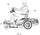
- the perpendicular distance D1 from the left cover member 162L to the plane on which the riding lawn mower 100 walks is greater than or equal to 45cm and less than or equal to 65cm. In one embodiment, the perpendicular distance D1 from the left cover member 162L to the plane on which the riding lawn mower 100 walks is greater than or equal to 50cm and less than or equal to 60cm. In one embodiment, the perpendicular distance D1 from the left cover member 162L to the plane on which the riding lawn mower 100 walks is about 55cm.
- the left cover member 162L has an oblique top surface, that is, the height of the front side of which is lower than the height of the rear side of the same, making the overall height of the left cover member 162L lower than that of the right cover member 162R. In this way, the user can hop onto the riding lawn mower 100 from the left side of the riding lawn mower 100 more obstacle-free.
- the perpendicular distance D2 from the outermost surface of the left cover member 162L to the central vertical plane 109 is greater than or equal to 30cm and less than or equal to 50cm. In one embodiment, the perpendicular distance D2 from the outermost surface of the left cover member 162L to the central vertical plane 109 is greater than or equal to 30cm and less than or equal to 50cm.
- the perpendicular distance D2 from the outermost surface of the left cover member 162L to the central vertical plane 109 is greater than or equal to 35cm and less than or equal to 45cm. In one embodiment, the perpendicular distance from the outermost surface of the left cover member 162L is about 39cm. Also, for users with taller heights and longer legs, the area that the user gets on and off the riding lawn mower 100 should be wide enough. Referring to FIG. 19 , in one embodiment, the distance D3 between orthographic projections of the front end of the riding lawn mower 100 and the rear end of the left cover member 162L on the plane on which the riding lawn mower 100 walks is greater than or equal to 100cm and less than or equal to 130cm.
- the distance D3 between orthographic projections of the front end of the riding lawn mower 100 and the rear end of the left cover member 162L on the plane on which the riding lawn mower 100 walks is greater than or equal to 110cm and less than or equal to 120cm. In one embodiment, the distance D3 between orthographic projections of the front end of the riding lawn mower 100 and the rear end of the left cover member 162L on the plane on which the riding lawn mower 100 walks is about 115cm.
- FIGS. 18-20 show a user 1.9m tall; for users with lower heights or shorter legs, the area that the user gets on and off the riding lawn mower 100 is more spacious.
- the riding lawn mower 100 further includes a step bar 163 mounted to the chassis 16, wherein the step bar 163 is located on an opposite side of central vertical plane 109 to the pedal assembly.
- the steering wheel assembly 136 and the pedal assembly are mounted to the left side of the riding lawn mower 100, whereas step bar 163 is mounted to the right side of the riding lawn mower 100.
- the step bar 163 is mounted to the right longitudinal beam 161R.
- the step bar 163 is foldable; specifically, the step bar 163 is rotatably mounted to the right longitudinal beam 161R through a hinge structure.
- the step bar 163 has a first position and a second position: in the first position, the step bar 163 is parallel to the chassis, wherein the step bar 163 extends out from the right longitudinal beam 161R, the user can step on the step bar 163 when getting onto the riding lawn mower 100; in the second position, the step bar 163 is perpendicular to the chassis, wherein the step bar 163 clings to the right longitudinal beam 161R to save space.
- the operating assembly 13 further includes a control panel 137.
- the control panel 137 may include a plurality of buttons, wherein different buttons correspond to different commands.
- the buttons of the control panel 137 may include a lighting button configured to enable or disable the lighting assembly 18, a mode button configured to select and set a driving mode of the riding lawn mower 100, a configuration button configured to modify the various settings of the riding lawn mower 100, and a speed regulator button to increase or decrease the walking or cutting speed of the riding lawn mower 100.
- the operating assembly 13 may also include a display interface 138, which displays the operating status of the riding lawn mower 100.
- the display interface 138 can display the walking speed of the walking assembly, the rotational speed of the cutting assembly, the energy efficiency status of the riding lawn mower 100, the remaining capacity of the power supply assembly 14, warning information, fault information, and so on.
- control panel 137 and the display interface 138 are integrated with the steering wheel assembly 136.
- the control panel 137 is arranged in the centre of the steering wheel 1362
- the display interface 138 is arranged in the center of the control panel 137.
- the steering wheel 1362 is substantially symmetrical about a second axis 108; the control panel 137 is also substantially symmetrical about the second axis 108; the display interface 138 is also substantially symmetrical about the second axis 108.
- the buttons of the control panel 137 are distributed around the display interface 138.
- the display interface 138 is substantially rectangular, the size L2 of the display interface 138 in the length direction is greater than or equal to 100 mm and less than or equal to 150 mm, and the size L3 of the display interface 138 in the width direction is greater than or equal to 60 mm and less than or equal to 90 mm.
- the area of the display interface 138 is greater than or equal to 70 square centimeters and less than or equal to 110 square centimeters. In this way, the size of the display interface 138 is large enough to display enough information, and at the same time, small enough to fit in the center of the control panel 137, which fit in the center of the steering wheel 1362.
- the display interface 138 may also be an interactive display interface, which is enabled to receive user instructions. The user inputs different control commands through the control panel 137 and/or the display interface 138 to control the walking and cutting function of the riding lawn mower 100.
- the outer frame of the steering wheel 1362 is more of the shape of an oval.
- the outer frame of the steering wheel 1362 surrounds the rectangular display interface 138 or the control panel 137 more evenly, leaving a generally equal distance between the outer frame of the steering wheel 1362 and the control panel 137, thereby providing the user with more choices on which portion of the steering wheel 1362 to grip or hold.
- an oval does not have uniform diameters, so the outer frame of the steering wheel 1362 has a larger dimension defined as its width and a smaller dimension defined as its height. The larger dimension allows a generous width of the steering wheel 1362 so that the user holds the steering wheel 1362 with both hands more comfortably; the smaller dimension allows a lower height of the steering wheel 1362 so that a clearer view is left for the user to observe the environment.
- the steering wheel 1362 is formed with a gap 2203 on the top side of the steering wheel 1362, wherein the gap 2203 is also substantially symmetrical about the second axis 108.
- the gap 2203 further removes obstacles in the user's sight, leaving user's sight unblocked.
- the outer frame of the steering wheel 1362 is disconnected due to the gap 2203, and the disconnected ends are shaped for the user to grip.
- the gap 2203 can be replaced by a transparent portion. That is, the outer frame of the steering wheel 1362 is still continuous, but the top side of the steering wheel 1362 is made of transparent materials.
- the length of the gap 2203 or the transparent portion is greater than or equal to 1/10 of a perimeter of the steering wheel 1362 and less than or equal to 1/2 of the perimeter of the steering wheel 1362. In one embodiment, the length of the gap 2203 or the transparent portion is greater than or equal to 1/9 of a perimeter of the steering wheel 1362 and less than or equal to 1/3 of the perimeter of the steering wheel 1362.
- the position of the steering wheel assembly 136 in the working position is carefully designed.
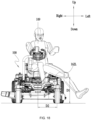
- the height of the steering wheel assembly 136 may be defined as the perpendicular distance D4 from a highest point of the steering wheel assembly 136 to the plane on which the riding lawn mower 100 walks. The lower the height of the steering wheel assembly 136, the better the view of the user, however, when the height of the steering wheel assembly 136 is too low, the operating experience of the steering wheel assembly 136 may suffer.
- the perpendicular distance D4 from a highest point of the steering wheel assembly 136 to the plane on which the riding lawn mower 100 walks is greater than or equal to 85cm and less than or equal to 125cm. In one embodiment, when the steering wheel assembly 136 is in the working position, the perpendicular distance D4 from a highest point of the steering wheel assembly 136 to the plane on which the riding lawn mower 100 walks is greater than or equal to 95cm and less than or equal to 115cm. In one embodiment, when the steering wheel assembly 136 is in the working position, the perpendicular distance D4 from a highest point of the steering wheel assembly 136 to the plane on which the riding lawn mower 100 walks is about 105cm.
- the difference of the height of the steering wheel assembly 136 and the height of the sitting surface of the seat i.e., the height difference of the steering wheel assembly 136 and the sitting surface of the seat, also affects user's view.
- the smaller the height difference the better the view of the user, however, when the height difference is too small, the legroom may be insufficient, causing an uncomfortable sitting experience.
- the difference D5 of a perpendicular distance from a highest point of the steering wheel assembly 136 to the plane on which the riding lawn mower 100 walks and a perpendicular distance from the sitting surface of the seat to the plane on which the riding lawn mower 100 walks is greater than or equal to 30cm and less than or equal to 55cm.
- the difference D5 of a perpendicular distance from a highest point of the steering wheel assembly 136 to the plane on which the riding lawn mower 100 walks and a perpendicular distance from the sitting surface of the seat to the plane on which the riding lawn mower 100 walks is greater than or equal to 35cm and less than or equal to 50cm. In one embodiment, when the steering wheel assembly 136 is in the working position, the difference D5 of a perpendicular distance from a highest point of the steering wheel assembly 136 to the plane on which the riding lawn mower 100 walks and a perpendicular distance from the sitting surface of the seat to the plane on which the riding lawn mower 100 walks is about 42cm.
- the distance between the steering wheel assembly 136 and a back of the seat may also affect the user's view, assuming that the user sits back when operating the riding lawn mower 100.
- the distance D6 between orthographic projections of the steering wheel assembly 136 and the back of the seat on the plane on which the riding lawn mower 100 walks is greater than or equal to 60cm and less than or equal to 100cm. In one embodiment, when the steering wheel assembly 136 is in the working position, the distance D6 between orthographic projections of the steering wheel assembly 136 and the back of the seat on the plane on which the riding lawn mower 100 walks is greater than or equal to 70cm and less than or equal to 90cm. In one embodiment, when the steering wheel assembly 136 is in the working position, the distance D6 between orthographic projections of the steering wheel assembly 136 and the back of the seat on the plane on which the riding lawn mower 100 walks is 80cm.
- the control circuit 130 further has a third state 1303, in which the control circuit 130 stops the walking motor 123 and then permits the walking motor 123 to rotate reversely.
- the operating member 139 is operable to switch the control circuit 130 into the third state 1303.
- the control circuit 130 is switched into the third state 1303.
- the riding lawn mower 100 switches from walking forward to walking backward if the user presses the at least one paddle shifter for a time period greater than or equal to a first time threshold.
- the control circuit 130 determines if a rotational speed of the motor is less than or equal to a first velocity threshold, and if the rotational speed of the motor is less than or equal to the first velocity threshold, the control circuit 130 is switched into the third state 1303.
- the riding lawn mower 100 first decelerates in the forward direction until the walking speed is 0, and then accelerates in the backward direction; that is, the control circuit 130 first decelerates the rotational speed of the walking motor 123 until the rotational speed of the walking motor 123 is 0, and then rotate the walking motor 123 reversely.
- the user also operates the pedal assembly 131 and the steering wheel assembly 136 to control the walking speed and the walking direction of the riding lawn mower 100 when walking reversely.
- a maximum rotational speed of the motor when the control circuit 130 is in the third state 1303 is less than a maximum rotational speed of the motor when the control circuit 130 is in the first state 1301.
- a maximum turning angle of the riding lawn mower when the control circuit 130 is in the third state 1303 is less than a maximum turning angle of the motor when the control circuit 130 is in the first state 1301.
- the control circuit 130 When the control circuit 130 is in the third state 1303 and the at least one paddle shifter 139 is released, the control circuit 130 is switched into the first state 1301. In other words, the riding lawn mower 100 switches from walking backward to walking forward if the user releases the at least one paddle shifter 139. That is, the user needs to keep pressing the at least one paddle shifter 139 when the riding lawn mower 100 walks backward.
- the riding lawn mower 100 first decelerates in the backward direction until the walking speed is 0, and then accelerates in the forward direction; that is, the control circuit 130 first decelerates the rotational speed of the walking motor 123 until the rotational speed of the walking motor 123 is 0, and then rotate the walking motor 123 forwardly.
- the riding lawn mower 100 provides the user with different driving modes.
- the user may select the driving mode through the mode button.
- Different driving modes are configured with different responsiveness, thus giving the user a bunch of driving experiences to select from.
- the riding lawn mower 100 has a standard mode, a control mode, and a sports mode.
- the acceleration of the control circuit 130 switching from the first state 1301 to the third state 1303 varies across the plurality of driving modes.
- the sport mode is configured with the fastest acceleration among the three driving modes, and as a consequence, the sport mode switches the fastest from walking forward to walking backward or from walking backward to walking forward.
- the standard mode is configured with a slower acceleration than that of the sport mode, and as a consequence, the standard mode switches slower from walking forward to walking backward or from walking backward to walking forward.
- the control mode is configured with a slowest acceleration among the three driving modes, and as a consequence, the control mode switches the slowest from walking forward to walking backward or from walking backward to walking forward.
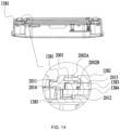
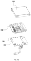
- the display interface 138 includes a casing 1381, a screen layer 1380 accommodated in the casing 1381, and a printed circuit board 1385.
- the screen layer 1380 may be an LCD screen or an LED screen, which is not limited herein. As detailed optical construction of the screen itself is not a contribution of this disclosure, the screen layer 1380 is simplified for the purpose of description.
- the screen layer 1380 includes a middle layer 1383 and a back layer 1384.
- the middle layer 1383 forms a light channel that guides and converts backlight.
- the middle layer 1383 may include an LED strip, a polarizer layer, a liquid crystal layer, a color filter layer, and a light guide plate, which are not shown in the drawings.
- the back layer 1384 may be a reflector sheet that reflects backlight.
- the backlight arrangement may be either edge LED or direct LED, which is not limited herein.
- the casing 1381 includes a cover layer 1382, which is a transparent protection cover, to protect and display the screen layer 1380.
- the cover layer 1382, the middle layer 1383, the back layer 1384, and the printed circuit board 1385 are stacked and mounted to the casing 1381, i.e., the middle layer 1383 disposed under the cover layer 1382, the back layer 1384 disposed under the middle layer 1383, and the printed circuit board 1385 disposed under the back layer 1384.
- the printed circuit board 1385 is mounted to the casing 1381 through at least one fastener, such as, screw. In one embodiment, the printed circuit board 1385 is integrated with switches for the buttons of the control panel 137, so that the printed circuit board 1385 not only transmits graphic signals for the display interface 138, but also transmits switch signals for the buttons of the control panel 137.
- the cover layer 1382 includes a projecting portion 2001 extending from its side surfaces.
- the casing 1381 includes a mating portion 2002 for mating with the projecting portion 2001 of the cover layer 1382.
- the mating portion 2002 includes two edges, respectively an upper edge 2002A and a lower edge 2002B.
- the upper edge 2002A and the lower edge 2002B form a groove 2003 in between.
- the projecting portion 2001 of the cover layer 1382 mates with the groove 2003 of the casing 1381 so as to mount the cover layer 1382 to the casing 1381.
- they are capsulated together.
- the casing 1381 and the cover layer 1382 is one piece, that is, the casing 1381 and the cover layer 1382 are integrated together, in one embodiment, the casing 1381 is made of tempered glass or transparent polycarbonate (PC) materials.
- the casing 1381 can be assembled to a gardening tool or power tool through fasteners, such as screws.
- the specific position that the flexible adhesives are applied to may be slightly different, which is not limited herein.
- double seals are created to safely seal the space between the cover layer 1382 and the screen layer 1380.
- flexible adhesives are applied to fill the space between the lower surface of the lower edge 2002B and the upper surface of the middle layer 1383, thereby forming a first seal 2011.
- flexible adhesives are applied to fill the space between the rib portion 2004 of the back layer 1384 and an inner wall of the casing 1381, thereby forming a second seal 2012.
- the specific positions that the first seal 2011 and the second seal 2012 are applied to may be slightly different, which is not limited herein.
- a first chamber 2013 is formed between the cover layer 1382 and the screen layer 1830, specifically, between the cover layer 1382 and the middle layer 1383.
- a second chamber 2014 is formed between the inner wall of the casing 1381 and side surface of the screen layer 1830, specifically, between the inner wall of the casing 1381 and the side surfaces of the middle layer 1383 and the back layer 1384.
- the first chamber 2013 and the second chamber 2014 abut.
- the thickness of the cover layer 1382 is greater than or equal to 2mm and less than or equal to 5mm. Or, the thickness of the cover layer 1382 is greater than or equal to 3mm and less than or equal to 4mm. In one embodiment, the thickness of the cover layer 1382 is 3.5mm. As the cover layer 1382 in this disclosure is made relatively thick, the cover layer 1382 is less prone to deformation, bending or dent. As a result, the distance D7 between the cover layer 1382 and the screen layer 1830, specifically, the distance D7 between the cover layer 1382 and the middle layer 1383, i.e., the height of the first chamber 2013, can be made relatively small.
- the anti-fogging effect depends largely on the durability of the seals, i.e., the first seal 2011 and the second seal 2012. If the seals become aging and cracked, moisture from the environment can enter the first chamber 2013, causing fogs on the display interface 138.
- the first seal 2011 and the second seal 2012 provide double protection.
- the first seal can still seal the first chamber; if the first seal breaks and the second seal still functions, the second seal can still seal the space of the first chamber plus the second chamber.
- the first chamber 2013 and the second chamber 2014 play a role in force balancing.
- the air sealed in the first chamber 2013 expands if the environment temperature is high and contracts if the environment temperature is low, causing pushing force (when expending) and pulling force (when contracting) to the first seal 2011, which is damaging for the reliability and durability of the first seal 2011 over time.
- the volume of the air sealed by the first seal 2011 in the first chamber 2013 is small, therefore the force applied to the first seal 2011 generated from thermal expansion and contraction of the air in the first chamber 2013 is limited.
- the air sealed in the second chamber 2014 When the environment temperature changes, the air sealed in the second chamber 2014 also expands if the environment temperature is high and contracts if the environment temperature is low. In other words, the air sealed in the second chamber 2014 expands and contracts substantially synchronously with the air sealed in the first chamber 2013. As the first chamber 2013 and the second chamber 2014 abut and share the first seal 2011 as a common boundary, the force applied to the first seal 2011 generated from thermal expansion and contraction of the air in the second chamber 2014 at least partially offsets the force applied to the first seal 2011 generated from thermal expansion and contraction of the air in the first chamber 2013, thereby the first seal 2011 suffers from less pushing force and pulling force during temperature change, making the first seal 2011 more durable.
- the structure described above is simple, compact, and highly reliable, forming an independent display assembly, which is convenient for assembly, maintenance, and replacement. It is understood that, the structure is not limited to display screens on riding lawn mowers, the structure is also applicable to display screens on other power tools for anti-fogging purposes.
- the display interface 138 may not include a screen layer 1380. That is, the display interface 138 does not have an LED screen or an LCD screen. Instead, as shown in FIG. 16 , the display interface 138 includes a casing 1381 and a printed circuit board 1385 accommodated in the casing 1381.
- the casing 1381 may be made of tempered glass or polycarbonate (PC) materials, and the thickness of the casing 1381 is greater than 2mm and less than or equal to 5mm.
- the printed circuit board has a plurality of light-emitting elements 1388, such as LED lamp beads.
- the display interface 138 further includes a light-guiding layer 1389 engraved with light-guiding channels.
- the light-guiding layer 1389 may be a separate part or formed integrally with the casing 1381 as one piece.
- a sticker (not shown) may be adhered to the casing 1381 or the light-guiding layer 1388 to further improve the display effect.
- flexible adhesives are applied between the printed circuit board 1385 and the casing 1381 to seal a chamber at least including a space between the printed circuit board 1385 and the casing 1381.
- the independently sealed display interface 138 can then be assembled to a variety of gardening tools or power tools.
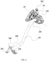
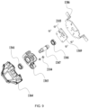
- the steering wheel assembly 136 includes a rotary shaft 1367 that is configured to form a synchronous rotation with the steering wheel 1362.
- the mounting assembly rotatably connects the steering wheel 1362 and the connecting rod 1361; in one embodiment, the mounting assembly rotatably supports the rotary shaft 1367.
- the mounting assembly further includes a mounting box 1364, which is fixedly connected to the connecting rod 1361 and rotatably supports the rotary shaft 1367.
- the mounting box 1364 may be formed in two halves and the two halves enclose the first end 2201 of the connecting rod 1361.
- the rotary shaft 1367 is fixedly coupled to the steering wheel 1362.
- the rotary shaft 1367 rotates synchronously with the steering wheel 1362.
- the steering wheel 1362 and the rotary shaft 1367 both rotate about the first axis 107.
- the steering wheel 1362 has a base plate 1386 and a fixing plate 1369, wherein the fixing plate 1369 is fixed to the base plate 1386 through a plurality of fasteners.
- the rotary shaft 1367 is engaged with at least one of the fixing plate 1369 and the base plate 1386, for example, through a flat fit.
- the base plate 1386 has a double D hole
- the fixing plate 1369 also has a double D hole
- the rotary shaft 1367 has a double D portion which fits in the double D hole of the fixing plate 1369 and the base plate 1386.
- the rotary shaft 1367 is welded to the fixing plate 1369, thereby forming synchronous rotation with the fixing plate 1369. This structure ensures the stable connection between the rotary shaft 1367 and the steering wheel 1362.
- the mounting assembly further includes a supporting member 1365 and at least one bearing.
- the supporting member 1365 is accommodated inside the mounting box 1364; in one embodiment, the supporting member 1365 is also fixed to the first end 2201 of the connecting rod 1361, for example, through fastening devices.
- the supporting member 1365 is formed with a channel for the rotary shaft 1367 a t least one bearing pedestal for the at least one bearing.
- the at least one bearing is mounted to the supporting member 1365, and the rotary shaft 1367 is rotatably supported by the at least one bearing. In one embodiment, there are two bearings supporting an upper portion of the rotary shaft 1367 and a lower portion of the rotary shaft 1367, respectively.
- the specific structure of the supporting member 1365 is not limited herein, as long as it supports the rotary shaft 1367 and enables the rotary shaft 1367 to rotate. In fact, the supporting member 1365 is not necessary if the mounting box 1364 is formed with corresponding structures to rotatably support the rotary shaft 1367.
- the steering wheel assembly 136 includes an adjustment device operable to adjust the height of the steering wheel 1362.
- the adjustment device enables at least one of the supporting member 1365 and the mounting box 1364 to move in the up and down direction with respect to the connecting rod 1361, while the position of the adjustment device is fixed with respect to the connecting rod 1361.
- the supporting member 1365 is formed in the shape of a cylinder, and the adjustment device is enabled to fix to different positions of the cylinder. When the adjustment device is fixed to a lower position of the cylinder, the height of the steering wheel 1362 is relatively high; when the adjustment device is fixed to a higher position of the cylinder, the height of the steering wheel 1362 is relatively low.
- the rotary shaft 1367 has a through hole, which allows a cable, or wire, to pass through the through hole.
- One end of the cable is connected to a first circuit board 1387, and the other end of the cable is connected to a second circuit board.
- the second circuit board is the printed circuit board 1385 of the display interface 138.
- the wire 1393 of the switch 1391 coupled with the operating member 139 is connected to the printed circuit board 1385 to reduce the number of wires.
- the wire 1393 of the switch 1391 coupled to the left paddle shifter 139L is connected to the printed circuit board 1385
- the wire 1393 of the switch 1391 coupled to the right paddle shifter 139R is connected to the printed circuit board 1385.
- the printed circuit board 1385 is the carrier for the switch signals of the operating member 139, the graphic signals of the display interface 138, and the switch signals of the buttons of the control panel 137. Therefore, only one cable, cable, connected with the printed circuit board 1385, is configured to pass through the making the wiring simple and clean. As the cable is inside the through hole of the rotary shaft 1367, the cable will not wear out easily, prolonging the service life of the steering wheel assembly 136.
- the rotary shaft 1367 is coupled with a magnetic element
- the first circuit board 1387 has a position sensor that detects the angular position of the magnetic element.
- the magnetic element is hanging to a lower end of the rotary shaft 1367 and rotates synchronously with the rotary shaft 1367
- the first circuit board 1387 is located under the magnetic element, with the position sensor directly facing the magnetic element.
- Other constructions are also acceptable as long as the position sensor detects the angular position of the steering wheel 1362 and the first circuit board 1387 receives the position signals detected by the position sensor.
- the first circuit board 1387 is not only the carrier for the angular position signals of the steering wheel 1362, but also the carrier for the switch signals of the operating member 139, the graphic signals of the display interface 138, and the switch signals of the buttons of the control panel 137. Further, another cable is connected to the first circuit board 1387 and passes through the connecting rod 1361, so that other components of the riding lawn mower 100, such as the walking assembly 12, the lighting assembly 18 and the cutting assembly 11 can exchange information with the steering wheel assembly 136, the control panel 137 and the display interface 138.
- the fixing plate 1369 includes a stopper projection 2103 to limit an angle of rotation of the steering wheel 1362.
- the stopper projection 2103 may be formed in the shape of a hook protruding from the surface of the fixing plate 1369.
- the mounting box 1364 or the supporting member 1365 also includes a matching projection 2104 protruding out from the mounting box 1364 to limit the position of the stopper projection 2103.
- the supporting member 1365 is installed to the mounting box 1364 through at least one fastener, such as, for example, two bolts, and the two bolts are fastened to one side of the channel for the rotary shaft 1367.
- the heads of the two bolts protrude out from the mounting box 1364, wherein the head of the bolt is an example of the matching projection 2104, and there are two matching projections 2104.
- the distance between the mounting box 1364 and the fixing plate 1369 is less than the sum of the dimension of the stopper projection 2103 protruding out from the fixing plate 1369 and the dimension of the matching projection 2104 protruding out from the mounting box 1364, i.e., the height of the heads of the two bolts.
- the distance from the stopper projection 2103 to the first axis 107 and the distance from the matching projection 2104 to the first axis 107 are about the same.
- the fixing plate 1369 rotates until the stopper projection 2103 reaches one of the two matching projections 2104.
- the fixing plate 1369 rotates until the stopper projection 2103 reaches the other one of the two matching projections 2104.
- the at least one fastener is one bolt, so there is only one matching projection 2104.
- the fixing plate 1369 can rotate until the stopper projection 2103 reaches the matching projection 2104, no matter the fixing plate 1369 rotates in the clockwise direction or the counterclockwise direction.
- the at least one fastener realizes both functions of mounting the supporting member 1365 to the mounting box 1364 and limiting the position of the stopper projection 2103, so as to limit the angle of rotation of the steering wheel 1362.
- the at least one fastener is firm, durable, low cost, and replaceable easily.
- the matching projection 2104 is not a fastener; in fact, the matching projection 2104 may be any protruding structure that is configured to limit the rotational position of the stopper projection 2103.
- the steering wheel 1362 has a first limit position 2111 when rotating clockwise about the first axis, as shown in FIG. 12A and a second limit position 2112 when rotating counterclockwise about the first axis, as shown in FIG. 12B .
- the angle that the steering wheel 136 rotates from the first limit position 2111 to the second limit position 2112 is less than or equal to 380 degrees. In one embodiment, the angle that the steering wheel 136 rotates from the first limit position 2111 to the second limit position 2112 is less than or equal to 320 degrees. In one embodiment, the angle that the steering wheel 136 rotates from the first limit position 2111 to the second limit position 2112 is less than or equal to 240 degrees.
- the angle that the steering wheel 136 rotates from the first limit position 2111 to the second limit position 2112 is 270 degrees.
- the steering wheel 1362 is configured to rotate clockwise and counterclockwise for the same degrees, the angle that the steering wheel 136 rotates from the first limit position 2111 to the second limit position 2112 can split equally.
- the steering wheel 1362 further has an initial position 2113, in which the steering wheel 1362 is symmetrical about the second axis 108.
- the angle ⁇ 1 that the steering wheel 136 rotates from the initial position 2113 to the first limit position 2111 is less than or equal to 190 degrees
- the angle ⁇ 2 that the steering wheel 136 rotates from the initial position 2113 to the second limit position 2112 is less than or equal to 190 degrees
- the angle ⁇ 1 that the steering wheel 136 rotates from the initial position 2113 to the first limit position 2111 is less than or equal to 160 degrees
- the angle ⁇ 2 that the steering wheel 136 rotates from the initial position 2113 to the second limit position 2112 is less than or equal to 160 degrees.
- the angle ⁇ 1 that the steering wheel 136 rotates from the initial position 2113 to the first limit position 2111 is less than or equal to 120 degrees
- the angle ⁇ 2 that the steering wheel 136 rotates from the initial position 2113 to the second limit position 2112 is less than or equal to 120 degrees.
- the angle ⁇ 1 that the steering wheel 136 rotates from the initial position 2113 to the first limit position 2111 is 135 degrees
- the angle ⁇ 2 that the steering wheel 136 rotates from the initial position 2113 to the second limit position 2112 is 135 degrees.
- the steering wheel assembly 136 further includes a damper 2105, and the rotary shaft 1367 and the damper 2105 transmit force through a belt drive.
- the damper 2105 is a rotary damper, or called disk damper.
- the rotary shaft 1367 is coupled with a gearwheel 2107.
- the gearwheel 2107 has a double D hole, which fits in a double D portion of the rotary shaft 1367.
- the damper 2105 is also coupled with a gear 2108.
- the damper 2105 has a shaft 2109, and the gear 2108 is fixed to the shaft 2109 of the damper 2105.
- the gearwheel 2107 and the gear 2108 are both engaged with a belt 2106.
- the belt 2106 transmits force from the gearwheel 2107 to the gear 2108 and from the gear 2108 to the gearwheel 2107.
- the rotary shaft 1367 rotates, causing the gearwheel 2107 to rotate.
- the gearwheel 2107 rotates, the belt rotates and passes the rotary force to the gear 2108 and the shaft.
- the shaft rotates, the viscosity of the sealed oil in the damper's body will create resistance to the movement of the shaft 2109. This resistance (or called viscous friction) will slow down the movement speed of the steering wheel 1362.
- the damper 2105 moves, its torque is generally influenced by the viscosity of the sealed oil.
- the belt 2106 is further provided with a tension device 2110.
- at least part of the damper 2105 and the belt drive is accommodated inside the supporting member 1365, which provides better fixation and protection. It is noted that, the specific structure of the damper 2105 is not limited herein; and in some embodiments, the damper 2105 can be replaced by a motor to provide damping effect.
- the angular position of the steering wheel 1362 can be calculated from the rotational position of the motor and the transmission ratio of the belt drive, thereby eliminating the need for extra sensors for detecting the angular position of the steering wheel 1362.
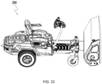
- aspects of this disclosure are also applicable to riding machines of other types, as long as the riding machine can output power in other forms besides walking power in order to realize other functions besides walking, for example, the riding snow blower 200 as shown in FIG. 22 also adopts the same or similar design of embodiments described above.
Landscapes
- Life Sciences & Earth Sciences (AREA)
- Environmental Sciences (AREA)
- Engineering & Computer Science (AREA)
- Chemical & Material Sciences (AREA)
- Combustion & Propulsion (AREA)
- Transportation (AREA)
- Mechanical Engineering (AREA)
- Harvester Elements (AREA)
Priority Applications (1)
| Application Number | Priority Date | Filing Date | Title |
|---|---|---|---|
| EP25156406.8A EP4527177A3 (de) | 2021-09-18 | 2021-09-18 | Aufsitzrasenmäher, anzeigeschnittstelle eines elektrowerkzeugs und aufsitzmaschine |
Applications Claiming Priority (3)
| Application Number | Priority Date | Filing Date | Title |
|---|---|---|---|
| EP25156406.8A EP4527177A3 (de) | 2021-09-18 | 2021-09-18 | Aufsitzrasenmäher, anzeigeschnittstelle eines elektrowerkzeugs und aufsitzmaschine |
| PCT/CN2021/119302 WO2023039874A1 (en) | 2021-09-18 | 2021-09-18 | Riding lawn mower, display interface of a power tool and riding machine |
| EP21957152.8A EP4231813B1 (de) | 2021-09-18 | 2021-09-18 | Aufsitzrasenmäher |
Related Parent Applications (1)
| Application Number | Title | Priority Date | Filing Date |
|---|---|---|---|
| EP21957152.8A Division EP4231813B1 (de) | 2021-09-18 | 2021-09-18 | Aufsitzrasenmäher |
Publications (2)
| Publication Number | Publication Date |
|---|---|
| EP4527177A2 true EP4527177A2 (de) | 2025-03-26 |
| EP4527177A3 EP4527177A3 (de) | 2025-05-07 |
Family
ID=85602353
Family Applications (2)
| Application Number | Title | Priority Date | Filing Date |
|---|---|---|---|
| EP21957152.8A Active EP4231813B1 (de) | 2021-09-18 | 2021-09-18 | Aufsitzrasenmäher |
| EP25156406.8A Pending EP4527177A3 (de) | 2021-09-18 | 2021-09-18 | Aufsitzrasenmäher, anzeigeschnittstelle eines elektrowerkzeugs und aufsitzmaschine |
Family Applications Before (1)
| Application Number | Title | Priority Date | Filing Date |
|---|---|---|---|
| EP21957152.8A Active EP4231813B1 (de) | 2021-09-18 | 2021-09-18 | Aufsitzrasenmäher |
Country Status (4)
| Country | Link |
|---|---|
| US (2) | US12035654B2 (de) |
| EP (2) | EP4231813B1 (de) |
| CN (2) | CN117202775A (de) |
| WO (1) | WO2023039874A1 (de) |
Families Citing this family (3)
| Publication number | Priority date | Publication date | Assignee | Title |
|---|---|---|---|---|
| WO2022075206A1 (ja) * | 2020-10-05 | 2022-04-14 | 株式会社クボタ | 電動トラクタ |
| CN119054491A (zh) * | 2023-06-02 | 2024-12-03 | 苏州宝时得电动工具有限公司 | 骑乘式割草机 |
| CN121420778A (zh) * | 2024-07-23 | 2026-01-30 | 南京泉峰科技有限公司 | 骑乘式割草机 |
Citations (1)
| Publication number | Priority date | Publication date | Assignee | Title |
|---|---|---|---|---|
| US3561282A (en) * | 1970-02-05 | 1971-02-09 | Int Harvester Co | Adjustable angle steering wheel mechanism for riding mower |
Family Cites Families (71)
| Publication number | Priority date | Publication date | Assignee | Title |
|---|---|---|---|---|
| US3732671A (en) * | 1971-08-31 | 1973-05-15 | Deere & Co | Electric drive riding mower |
| US5406778A (en) * | 1994-02-03 | 1995-04-18 | Ransomes America Corporation | Electric drive riding greens mower |
| US5713189A (en) | 1995-08-16 | 1998-02-03 | Ransomes America Corporation | Interactive brake system for electric riding mower |
| US5865016A (en) * | 1997-02-07 | 1999-02-02 | Ransomes America Corporation | Release mechanism for cutting head of a gang mower |
| US6092617A (en) | 1998-02-17 | 2000-07-25 | The Toro Company | System for automatically slowing vehicle during turns |
| WO1999062323A1 (en) | 1998-06-05 | 1999-12-09 | Mtd Products Inc. | Cruise control system |
| AU2003200523B2 (en) | 1998-08-17 | 2004-09-02 | Ransomes America Corporation | Electric drive mower |
| DE10229350A1 (de) | 2002-06-29 | 2004-01-15 | Dr. Johannes Heidenhain Gmbh | Verfahren zum Betätigen einer Haltebremse |
| US6997281B2 (en) * | 2002-11-26 | 2006-02-14 | General Motors Corporation | Driver control input device for drive-by-wire vehicle |
| JP4270079B2 (ja) | 2003-09-05 | 2009-05-27 | 日産自動車株式会社 | 駆動力制御装置 |
| JP4605649B2 (ja) | 2005-03-22 | 2011-01-05 | 株式会社クボタ | 草刈り機 |
| JP5119646B2 (ja) | 2006-03-06 | 2013-01-16 | 株式会社アドヴィックス | 車両用ブレーキ制御装置 |
| US20070295545A1 (en) | 2006-05-11 | 2007-12-27 | Romig Bernard E | Differential Steering and Traction Control For Electrically Propelled Mower |
| US20120159916A1 (en) | 2007-01-15 | 2012-06-28 | Kanzaki Kokyukoki Manufacturing Co., Ltd. | Control sysytem for motor-driven lawnmower vehicle |
| EP1943894B1 (de) | 2007-01-15 | 2010-05-19 | Kanzaki Kokyukoki Mfg. Co., Ltd. | Rasenmäher |
| US8207693B2 (en) | 2007-09-11 | 2012-06-26 | Hydro-Gear Limited Partnership | Controller assemblies for electric drive utility vehicles |
| US8011678B1 (en) * | 2007-09-20 | 2011-09-06 | Hydro-Gear Limited Partnership | Steering system for a zero-turn radius vehicle |
| JP2009078713A (ja) * | 2007-09-26 | 2009-04-16 | Honda Motor Co Ltd | 車両のスタート補助システム |
| US7894957B2 (en) | 2008-01-28 | 2011-02-22 | Textron Innovations Inc. | Dynamic tactical steering feedback |
| US7839106B2 (en) | 2008-03-05 | 2010-11-23 | Gm Global Technology Operations, Inc. | System and methods involving dynamic closed loop motor control and flux weakening |
| US7669580B2 (en) | 2008-03-24 | 2010-03-02 | Deere & Company | Electronic engine speed control system for grass mowing machine |
| US8544251B2 (en) * | 2008-06-27 | 2013-10-01 | The Toro Company | Reel mower with cutting units suspended by double A arm suspensions |
| FR2940881B1 (fr) | 2009-01-09 | 2011-01-21 | Etesia | Tondeuse electrique a conducteur porte et a alimentation autonome en fonctionnement |
| WO2010140929A1 (en) * | 2009-06-01 | 2010-12-09 | Andersson, Jonas | Lawn mower |
| US9624890B2 (en) * | 2009-11-19 | 2017-04-18 | Briggs & Stratton Corporation | Push button starting system module for outdoor power equipment |
| JP5521941B2 (ja) | 2010-09-24 | 2014-06-18 | 株式会社Ihi | 乗用型芝刈り車両及びその制御方法 |
| CN201941824U (zh) * | 2010-10-16 | 2011-08-24 | 合肥华信电动科技发展有限公司 | 电动车方向盘的旋钮开关 |
| JP5805437B2 (ja) * | 2011-06-14 | 2015-11-04 | 株式会社マキタ | 電動芝刈機 |
| US8838311B2 (en) | 2011-06-15 | 2014-09-16 | Kubota Corporation | Vehicle having independently driven and controlled right and left drive wheels |
| JP5933296B2 (ja) | 2011-07-29 | 2016-06-08 | 株式会社クボタ | 車両用変速制御システム |
| US9679419B2 (en) * | 2011-10-28 | 2017-06-13 | Husqvarna Ab | Indicator system for outdoor power equipment |
| CA2888220C (en) * | 2012-10-17 | 2017-01-17 | Husqvarna Ab | Smart ignition system |
| JP5648672B2 (ja) * | 2012-12-06 | 2015-01-07 | 井関農機株式会社 | 草刈機 |
| CN203410502U (zh) * | 2013-07-11 | 2014-01-29 | 上海格锐思实业有限公司 | 电动车舵式方向盘 |
| WO2015040987A1 (ja) | 2013-09-19 | 2015-03-26 | 日立工機株式会社 | 自走式草刈機 |
| CN104509297B (zh) * | 2013-09-30 | 2016-11-23 | 苏州宝时得电动工具有限公司 | 方向盘可调节的割草机 |
| CN104554255A (zh) | 2013-10-22 | 2015-04-29 | 沈阳工业大学 | 四轮全驱电动汽车底盘主动安全集成控制系统动态解耦方法 |
| JP6321970B2 (ja) | 2014-01-20 | 2018-05-09 | 株式会社クボタ | 芝刈機 |
| US20150308569A1 (en) | 2014-04-29 | 2015-10-29 | Parker-Hannifin Corporation | Controller and system for utility vehicle |
| CN104166372B (zh) | 2014-07-31 | 2017-04-05 | 西安交通大学苏州研究院 | 一种进给系统双位置环反馈的抗扰控制器 |
| US9616893B2 (en) | 2014-10-15 | 2017-04-11 | Honda Motor Co., Ltd. | Automatic turn-sensing ground speed reduction systems and related methods for walk-behind machines |
| US10058031B1 (en) | 2015-02-28 | 2018-08-28 | Hydro-Gear Limited Partnership | Lawn tractor with electronic drive and control system |
| JP6487827B2 (ja) | 2015-11-17 | 2019-03-20 | ヤンマー株式会社 | 作業車両 |
| CN105383544B (zh) * | 2015-11-25 | 2018-08-28 | 北京汽车股份有限公司 | 方向盘组件及汽车 |
| CN205454604U (zh) | 2016-01-22 | 2016-08-17 | 扬州维邦园林机械有限公司 | 一种电池动力草坪车 |
| JP6305453B2 (ja) | 2016-03-18 | 2018-04-04 | 本田技研工業株式会社 | 作業機 |
| US10394233B2 (en) * | 2016-05-20 | 2019-08-27 | Radio Flyer Inc. | Dual-controlled ride-on vehicle |
| JP2018102196A (ja) * | 2016-12-26 | 2018-07-05 | 本田技研工業株式会社 | 芝刈機 |
| US10356977B2 (en) | 2017-06-13 | 2019-07-23 | Deere + Company | Electric walk behind greens mower |
| JP6834837B2 (ja) | 2017-08-03 | 2021-02-24 | 井関農機株式会社 | 乗用芝刈り機 |
| WO2019035021A1 (en) * | 2017-08-16 | 2019-02-21 | Briggs & Stratton Corporation | NOZZLE ROLLING GUN MOWER HAVING FRONT AND REAR WHEELS RELATED IN RELATION TO A SINGLE PIVOT AXIS |
| CN107521456A (zh) * | 2017-09-29 | 2017-12-29 | 深圳市京弘全智能科技股份有限公司 | 一种具有自动识别功能的车辆启动装置 |
| JP6851504B2 (ja) | 2017-12-28 | 2021-03-31 | 三菱電機株式会社 | 電気車制御装置 |
| CN110313296B (zh) | 2018-03-28 | 2022-01-04 | 南京德朔实业有限公司 | 骑乘式割草机的操作装置以及骑乘式割草机 |
| CN111492783B (zh) | 2019-01-30 | 2023-09-12 | 南京泉峰科技有限公司 | 骑乘式草坪护理车 |
| US11785885B2 (en) * | 2019-01-31 | 2023-10-17 | The Toro Company | Mower with ganged reel cutting units having automatic clip control in both straight ahead motion and in turns |
| CN111756280A (zh) | 2019-03-28 | 2020-10-09 | 南京德朔实业有限公司 | 骑乘式割草机 |
| WO2020253821A1 (zh) | 2019-06-21 | 2020-12-24 | 南京德朔实业有限公司 | 骑乘式割草机 |
| CN211171513U (zh) | 2019-07-08 | 2020-08-04 | 青岛科泰重工机械有限公司 | 胶轮压路机的操控装置 |
| US11067326B2 (en) * | 2019-07-08 | 2021-07-20 | Haier Us Appliance Solutions, Inc. | Ice dispensing assemblies and methods for preventing clumping |
| WO2021004484A1 (zh) * | 2019-07-09 | 2021-01-14 | 南京德朔实业有限公司 | 骑乘式割草机及其控制方法 |
| CN210671321U (zh) | 2019-09-03 | 2020-06-05 | 绿友机械集团股份有限公司 | 一种坐骑式电动零转弯割草机 |
| CN110677079B (zh) | 2019-09-04 | 2021-02-26 | 深圳市百盛传动有限公司 | 一种永磁同步电机速度控制模式扰动观测器 |
| CN112740893B (zh) | 2019-10-29 | 2023-09-08 | 南京泉峰科技有限公司 | 骑乘式割草机 |
| CN211210526U (zh) * | 2019-11-04 | 2020-08-11 | 厦门纵横通电动车有限公司 | 一种新型电动割草机 |
| CN110989578B (zh) | 2019-11-15 | 2023-08-01 | 苏州博迷科技有限公司 | 一种可无线控制的双核四轮驱动uwb定位割草机器人及其控制方法 |
| CN110741810B (zh) * | 2019-12-09 | 2024-11-12 | 重庆大江动力设备制造有限公司 | 一种坐骑式割草机 |
| CN211793024U (zh) * | 2019-12-09 | 2020-10-30 | 重庆大江动力设备制造有限公司 | 一种坐骑式割草机 |
| CN111516747B (zh) * | 2020-03-25 | 2021-04-23 | 浙江中坚科技股份有限公司 | 零转角电动割草机的方向控制机构 |
| US12137625B2 (en) | 2021-03-15 | 2024-11-12 | Kubota Corporation | Work vehicle and control system for work vehicle |
| CN113243196A (zh) * | 2021-05-11 | 2021-08-13 | 绿友机械集团股份有限公司 | 一种电动驾乘式草坪修剪机的中排后集草刀盘 |
-
2021
- 2021-09-18 EP EP21957152.8A patent/EP4231813B1/de active Active
- 2021-09-18 CN CN202180091191.5A patent/CN117202775A/zh active Pending
- 2021-09-18 CN CN202511693026.3A patent/CN121369054A/zh active Pending
- 2021-09-18 WO PCT/CN2021/119302 patent/WO2023039874A1/en not_active Ceased
- 2021-09-18 EP EP25156406.8A patent/EP4527177A3/de active Pending
-
2023
- 2023-05-19 US US18/320,304 patent/US12035654B2/en active Active
-
2024
- 2024-06-11 US US18/740,179 patent/US12568880B2/en active Active
Patent Citations (1)
| Publication number | Priority date | Publication date | Assignee | Title |
|---|---|---|---|---|
| US3561282A (en) * | 1970-02-05 | 1971-02-09 | Int Harvester Co | Adjustable angle steering wheel mechanism for riding mower |
Also Published As
| Publication number | Publication date |
|---|---|
| US12035654B2 (en) | 2024-07-16 |
| US20230284560A1 (en) | 2023-09-14 |
| EP4231813A4 (de) | 2024-01-24 |
| EP4231813A1 (de) | 2023-08-30 |
| US20240324501A1 (en) | 2024-10-03 |
| US12568880B2 (en) | 2026-03-10 |
| CN121369054A (zh) | 2026-01-23 |
| EP4527177A3 (de) | 2025-05-07 |
| CN117202775A (zh) | 2023-12-08 |
| EP4231813B1 (de) | 2025-02-26 |
| WO2023039874A1 (en) | 2023-03-23 |
Similar Documents
| Publication | Publication Date | Title |
|---|---|---|
| US12035654B2 (en) | Riding lawn mower, display interface of a power tool and riding machine | |
| US11801882B2 (en) | Handcart | |
| US12103579B2 (en) | Working machine | |
| US20210039703A1 (en) | Handcart | |
| CA2728612A1 (en) | Model helicopter | |
| CN218634775U (zh) | 割草拖拉机 | |
| US20240081178A1 (en) | Riding mowing device | |
| KR20140046282A (ko) | 차량용 페달 수납 장치 | |
| CN116114474A (zh) | 骑乘式割草设备 | |
| CN213990263U (zh) | 动力头及动力工具 | |
| CN116114460A (zh) | 骑乘式割草设备 | |
| JP2008179218A (ja) | ヘッドアップディスプレイ装置 | |
| WO2023082770A1 (zh) | 骑乘式割草设备 | |
| JP4055376B2 (ja) | 車両用アウターミラー | |
| US20260020519A1 (en) | Robot Control Method, Apparatus, Electronic Device and Storage Medium | |
| CN116114457A (zh) | 割草拖拉机 | |
| CN116118915A (zh) | 骑乘式车辆 | |
| CN221784686U (zh) | 自主作业设备 | |
| US20250331452A1 (en) | Walk-behind working machine | |
| CN219029297U (zh) | 一种屏幕调节机构及车辆 | |
| CN117351617A (zh) | 电气设备 | |
| KR200370256Y1 (ko) | 자동차용 미러 | |
| KR20080048183A (ko) | 차량용 에이브이 시스템의 회전형 조작장치 | |
| KR20050047863A (ko) | 차량용 전동접힘 사이드 미러의 진동방지구조 | |
| JP2007001459A (ja) | 車両用フットレスト装置 |
Legal Events
| Date | Code | Title | Description |
|---|---|---|---|
| PUAI | Public reference made under article 153(3) epc to a published international application that has entered the european phase |
Free format text: ORIGINAL CODE: 0009012 |
|
| STAA | Information on the status of an ep patent application or granted ep patent |
Free format text: STATUS: THE APPLICATION HAS BEEN PUBLISHED |
|
| AC | Divisional application: reference to earlier application |
Ref document number: 4231813 Country of ref document: EP Kind code of ref document: P |
|
| AK | Designated contracting states |
Kind code of ref document: A2 Designated state(s): AL AT BE BG CH CY CZ DE DK EE ES FI FR GB GR HR HU IE IS IT LI LT LU LV MC MK MT NL NO PL PT RO RS SE SI SK SM TR |
|
| REG | Reference to a national code |
Ref country code: DE Ref legal event code: R079 Free format text: PREVIOUS MAIN CLASS: A01D0034690000 Ipc: A01D0034640000 |
|
| PUAL | Search report despatched |
Free format text: ORIGINAL CODE: 0009013 |
|
| AK | Designated contracting states |
Kind code of ref document: A3 Designated state(s): AL AT BE BG CH CY CZ DE DK EE ES FI FR GB GR HR HU IE IS IT LI LT LU LV MC MK MT NL NO PL PT RO RS SE SI SK SM TR |
|
| RIC1 | Information provided on ipc code assigned before grant |
Ipc: A01D 34/82 20060101ALI20250328BHEP Ipc: A01D 34/69 20060101ALI20250328BHEP Ipc: A01D 34/68 20060101ALI20250328BHEP Ipc: A01D 34/64 20060101AFI20250328BHEP |
|
| STAA | Information on the status of an ep patent application or granted ep patent |
Free format text: STATUS: REQUEST FOR EXAMINATION WAS MADE |
|
| 17P | Request for examination filed |
Effective date: 20250919 |
|
| STAA | Information on the status of an ep patent application or granted ep patent |
Free format text: STATUS: EXAMINATION IS IN PROGRESS |
|
| 17Q | First examination report despatched |
Effective date: 20251103 |