EP4231813B1 - Aufsitzrasenmäher - Google Patents
Aufsitzrasenmäher Download PDFInfo
- Publication number
- EP4231813B1 EP4231813B1 EP21957152.8A EP21957152A EP4231813B1 EP 4231813 B1 EP4231813 B1 EP 4231813B1 EP 21957152 A EP21957152 A EP 21957152A EP 4231813 B1 EP4231813 B1 EP 4231813B1
- Authority
- EP
- European Patent Office
- Prior art keywords
- steering wheel
- lawn mower
- riding lawn
- assembly
- walking
- Prior art date
- Legal status (The legal status is an assumption and is not a legal conclusion. Google has not performed a legal analysis and makes no representation as to the accuracy of the status listed.)
- Active
Links
Images


Classifications
-
- A—HUMAN NECESSITIES
- A01—AGRICULTURE; FORESTRY; ANIMAL HUSBANDRY; HUNTING; TRAPPING; FISHING
- A01D—HARVESTING; MOWING
- A01D34/00—Mowers; Mowing apparatus of harvesters
- A01D34/01—Mowers; Mowing apparatus of harvesters characterised by features relating to the type of cutting apparatus
- A01D34/412—Mowers; Mowing apparatus of harvesters characterised by features relating to the type of cutting apparatus having rotating cutters
- A01D34/63—Mowers; Mowing apparatus of harvesters characterised by features relating to the type of cutting apparatus having rotating cutters having cutters rotating about a vertical axis
- A01D34/82—Other details
- A01D34/824—Handle arrangements
-
- A—HUMAN NECESSITIES
- A01—AGRICULTURE; FORESTRY; ANIMAL HUSBANDRY; HUNTING; TRAPPING; FISHING
- A01D—HARVESTING; MOWING
- A01D34/00—Mowers; Mowing apparatus of harvesters
- A01D34/01—Mowers; Mowing apparatus of harvesters characterised by features relating to the type of cutting apparatus
- A01D34/412—Mowers; Mowing apparatus of harvesters characterised by features relating to the type of cutting apparatus having rotating cutters
- A01D34/63—Mowers; Mowing apparatus of harvesters characterised by features relating to the type of cutting apparatus having rotating cutters having cutters rotating about a vertical axis
- A01D34/64—Mowers; Mowing apparatus of harvesters characterised by features relating to the type of cutting apparatus having rotating cutters having cutters rotating about a vertical axis mounted on a vehicle, e.g. a tractor, or drawn by an animal or a vehicle
-
- A—HUMAN NECESSITIES
- A01—AGRICULTURE; FORESTRY; ANIMAL HUSBANDRY; HUNTING; TRAPPING; FISHING
- A01D—HARVESTING; MOWING
- A01D34/00—Mowers; Mowing apparatus of harvesters
- A01D34/01—Mowers; Mowing apparatus of harvesters characterised by features relating to the type of cutting apparatus
- A01D34/412—Mowers; Mowing apparatus of harvesters characterised by features relating to the type of cutting apparatus having rotating cutters
- A01D34/63—Mowers; Mowing apparatus of harvesters characterised by features relating to the type of cutting apparatus having rotating cutters having cutters rotating about a vertical axis
- A01D34/67—Mowers; Mowing apparatus of harvesters characterised by features relating to the type of cutting apparatus having rotating cutters having cutters rotating about a vertical axis hand-guided by a walking operator
- A01D34/68—Mowers; Mowing apparatus of harvesters characterised by features relating to the type of cutting apparatus having rotating cutters having cutters rotating about a vertical axis hand-guided by a walking operator with motor driven cutters or wheels
- A01D34/6806—Driving mechanisms
- A01D34/6818—Motor starting mechanisms
-
- A—HUMAN NECESSITIES
- A01—AGRICULTURE; FORESTRY; ANIMAL HUSBANDRY; HUNTING; TRAPPING; FISHING
- A01D—HARVESTING; MOWING
- A01D34/00—Mowers; Mowing apparatus of harvesters
- A01D34/01—Mowers; Mowing apparatus of harvesters characterised by features relating to the type of cutting apparatus
- A01D34/412—Mowers; Mowing apparatus of harvesters characterised by features relating to the type of cutting apparatus having rotating cutters
- A01D34/63—Mowers; Mowing apparatus of harvesters characterised by features relating to the type of cutting apparatus having rotating cutters having cutters rotating about a vertical axis
- A01D34/67—Mowers; Mowing apparatus of harvesters characterised by features relating to the type of cutting apparatus having rotating cutters having cutters rotating about a vertical axis hand-guided by a walking operator
- A01D34/68—Mowers; Mowing apparatus of harvesters characterised by features relating to the type of cutting apparatus having rotating cutters having cutters rotating about a vertical axis hand-guided by a walking operator with motor driven cutters or wheels
- A01D34/69—Mowers; Mowing apparatus of harvesters characterised by features relating to the type of cutting apparatus having rotating cutters having cutters rotating about a vertical axis hand-guided by a walking operator with motor driven cutters or wheels with motor driven wheels
-
- A—HUMAN NECESSITIES
- A01—AGRICULTURE; FORESTRY; ANIMAL HUSBANDRY; HUNTING; TRAPPING; FISHING
- A01D—HARVESTING; MOWING
- A01D69/00—Driving mechanisms or parts thereof for harvesters or mowers
- A01D69/02—Driving mechanisms or parts thereof for harvesters or mowers electric
-
- B—PERFORMING OPERATIONS; TRANSPORTING
- B60—VEHICLES IN GENERAL
- B60K—ARRANGEMENT OR MOUNTING OF PROPULSION UNITS OR OF TRANSMISSIONS IN VEHICLES; ARRANGEMENT OR MOUNTING OF PLURAL DIVERSE PRIME-MOVERS IN VEHICLES; AUXILIARY DRIVES FOR VEHICLES; INSTRUMENTATION OR DASHBOARDS FOR VEHICLES; ARRANGEMENTS IN CONNECTION WITH COOLING, AIR INTAKE, GAS EXHAUST OR FUEL SUPPLY OF PROPULSION UNITS IN VEHICLES
- B60K26/00—Arrangement or mounting of propulsion-unit control devices in vehicles
- B60K26/02—Arrangement or mounting of propulsion-unit control devices in vehicles of initiating means or elements
-
- B—PERFORMING OPERATIONS; TRANSPORTING
- B62—LAND VEHICLES FOR TRAVELLING OTHERWISE THAN ON RAILS
- B62D—MOTOR VEHICLES; TRAILERS
- B62D1/00—Steering controls, i.e. means for initiating a change of direction of the vehicle
- B62D1/02—Steering controls, i.e. means for initiating a change of direction of the vehicle vehicle-mounted
- B62D1/04—Hand wheels
- B62D1/046—Adaptations on rotatable parts of the steering wheel for accommodation of switches
-
- A—HUMAN NECESSITIES
- A01—AGRICULTURE; FORESTRY; ANIMAL HUSBANDRY; HUNTING; TRAPPING; FISHING
- A01D—HARVESTING; MOWING
- A01D34/00—Mowers; Mowing apparatus of harvesters
- A01D34/01—Mowers; Mowing apparatus of harvesters characterised by features relating to the type of cutting apparatus
- A01D34/412—Mowers; Mowing apparatus of harvesters characterised by features relating to the type of cutting apparatus having rotating cutters
- A01D34/63—Mowers; Mowing apparatus of harvesters characterised by features relating to the type of cutting apparatus having rotating cutters having cutters rotating about a vertical axis
- A01D34/67—Mowers; Mowing apparatus of harvesters characterised by features relating to the type of cutting apparatus having rotating cutters having cutters rotating about a vertical axis hand-guided by a walking operator
- A01D34/68—Mowers; Mowing apparatus of harvesters characterised by features relating to the type of cutting apparatus having rotating cutters having cutters rotating about a vertical axis hand-guided by a walking operator with motor driven cutters or wheels
- A01D2034/6843—Control levers on the handle of the mower
-
- A—HUMAN NECESSITIES
- A01—AGRICULTURE; FORESTRY; ANIMAL HUSBANDRY; HUNTING; TRAPPING; FISHING
- A01D—HARVESTING; MOWING
- A01D2101/00—Lawn-mowers
-
- A—HUMAN NECESSITIES
- A01—AGRICULTURE; FORESTRY; ANIMAL HUSBANDRY; HUNTING; TRAPPING; FISHING
- A01D—HARVESTING; MOWING
- A01D34/00—Mowers; Mowing apparatus of harvesters
- A01D34/01—Mowers; Mowing apparatus of harvesters characterised by features relating to the type of cutting apparatus
- A01D34/412—Mowers; Mowing apparatus of harvesters characterised by features relating to the type of cutting apparatus having rotating cutters
- A01D34/63—Mowers; Mowing apparatus of harvesters characterised by features relating to the type of cutting apparatus having rotating cutters having cutters rotating about a vertical axis
- A01D34/76—Driving mechanisms for the cutters
- A01D34/78—Driving mechanisms for the cutters electric
-
- B—PERFORMING OPERATIONS; TRANSPORTING
- B60—VEHICLES IN GENERAL
- B60K—ARRANGEMENT OR MOUNTING OF PROPULSION UNITS OR OF TRANSMISSIONS IN VEHICLES; ARRANGEMENT OR MOUNTING OF PLURAL DIVERSE PRIME-MOVERS IN VEHICLES; AUXILIARY DRIVES FOR VEHICLES; INSTRUMENTATION OR DASHBOARDS FOR VEHICLES; ARRANGEMENTS IN CONNECTION WITH COOLING, AIR INTAKE, GAS EXHAUST OR FUEL SUPPLY OF PROPULSION UNITS IN VEHICLES
- B60K26/00—Arrangement or mounting of propulsion-unit control devices in vehicles
- B60K26/02—Arrangement or mounting of propulsion-unit control devices in vehicles of initiating means or elements
- B60K2026/024—Adjustable consoles, e.g. for changing position of mounting casings
-
- B—PERFORMING OPERATIONS; TRANSPORTING
- B60—VEHICLES IN GENERAL
- B60K—ARRANGEMENT OR MOUNTING OF PROPULSION UNITS OR OF TRANSMISSIONS IN VEHICLES; ARRANGEMENT OR MOUNTING OF PLURAL DIVERSE PRIME-MOVERS IN VEHICLES; AUXILIARY DRIVES FOR VEHICLES; INSTRUMENTATION OR DASHBOARDS FOR VEHICLES; ARRANGEMENTS IN CONNECTION WITH COOLING, AIR INTAKE, GAS EXHAUST OR FUEL SUPPLY OF PROPULSION UNITS IN VEHICLES
- B60K26/00—Arrangement or mounting of propulsion-unit control devices in vehicles
- B60K26/02—Arrangement or mounting of propulsion-unit control devices in vehicles of initiating means or elements
- B60K2026/025—Input devices for controlling electric drive motors
-
- B—PERFORMING OPERATIONS; TRANSPORTING
- B60—VEHICLES IN GENERAL
- B60K—ARRANGEMENT OR MOUNTING OF PROPULSION UNITS OR OF TRANSMISSIONS IN VEHICLES; ARRANGEMENT OR MOUNTING OF PLURAL DIVERSE PRIME-MOVERS IN VEHICLES; AUXILIARY DRIVES FOR VEHICLES; INSTRUMENTATION OR DASHBOARDS FOR VEHICLES; ARRANGEMENTS IN CONNECTION WITH COOLING, AIR INTAKE, GAS EXHAUST OR FUEL SUPPLY OF PROPULSION UNITS IN VEHICLES
- B60K26/00—Arrangement or mounting of propulsion-unit control devices in vehicles
- B60K26/02—Arrangement or mounting of propulsion-unit control devices in vehicles of initiating means or elements
- B60K2026/028—Acceleration input members mounted on steering wheel or column
-
- B—PERFORMING OPERATIONS; TRANSPORTING
- B60—VEHICLES IN GENERAL
- B60L—PROPULSION OF ELECTRICALLY-PROPELLED VEHICLES; SUPPLYING ELECTRIC POWER FOR AUXILIARY EQUIPMENT OF ELECTRICALLY-PROPELLED VEHICLES; ELECTRODYNAMIC BRAKE SYSTEMS FOR VEHICLES IN GENERAL; MAGNETIC SUSPENSION OR LEVITATION FOR VEHICLES; MONITORING OPERATING VARIABLES OF ELECTRICALLY-PROPELLED VEHICLES; ELECTRIC SAFETY DEVICES FOR ELECTRICALLY-PROPELLED VEHICLES
- B60L2200/00—Type of vehicles
- B60L2200/40—Working vehicles
-
- B—PERFORMING OPERATIONS; TRANSPORTING
- B60—VEHICLES IN GENERAL
- B60L—PROPULSION OF ELECTRICALLY-PROPELLED VEHICLES; SUPPLYING ELECTRIC POWER FOR AUXILIARY EQUIPMENT OF ELECTRICALLY-PROPELLED VEHICLES; ELECTRODYNAMIC BRAKE SYSTEMS FOR VEHICLES IN GENERAL; MAGNETIC SUSPENSION OR LEVITATION FOR VEHICLES; MONITORING OPERATING VARIABLES OF ELECTRICALLY-PROPELLED VEHICLES; ELECTRIC SAFETY DEVICES FOR ELECTRICALLY-PROPELLED VEHICLES
- B60L50/00—Electric propulsion with power supplied within the vehicle
- B60L50/50—Electric propulsion with power supplied within the vehicle using propulsion power supplied by batteries or fuel cells
- B60L50/60—Electric propulsion with power supplied within the vehicle using propulsion power supplied by batteries or fuel cells using power supplied by batteries
Definitions
- Lawn mowers are widely used in gardening to trim lawn and vegetation. Lawn mowers generally include hand push lawn mowers and riding lawn mowers. A user sits on and drives the riding lawn mower to perform lawn mowing tasks, making lawn mowing more efficient and less tiring. How to improve the driving experience of the riding lawn mower has been a subject that engineers have been consistently working on.
- the present invention provides a riding lawn mower with an integrated steering wheel assembly to provide the user operating the riding lawn mower with a comfortable driving experience.
- the riding lawn mower further includes a left cover member and a right cover member, the left cover member is located on a left side of the seat and the right cover member is located on a right side of the seat.
- the right cover member covers the pivot assembly.
- a height of the left cover member is lower than a height of the right cover member.
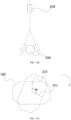
- a difference of a perpendicular distance from a highest point of the steering wheel assembly to the plane and a perpendicular distance from a sitting surface of the seat to the plane is greater than or equal to 30cm and less than or equal to 50cm.
- a perpendicular distance from a highest point of the steering wheel assembly to the plane is greater than or equal to 80cm and less than or equal to 120cm.
- a distance between orthographic projections of the steering wheel assembly and a back of the seat on the plane is greater than or equal to 60cm and less than or equal to 100cm.
- the steering wheel assembly further includes an adjustment device operable to adjust a height of the steering wheel.
- the riding lawn mower further includes a pedal assembly, the riding lawn mower has a central axis, the riding lawn mower is at least partially symmetrical about a central vertical plane passing through the central axis, the pedal assembly and the second end are located on a same side of the central vertical plane.
- a riding lawn mower including: a seat for a user to sit thereon; a chassis configured to support the seat; a cutting assembly mounted to the chassis, the cutting assembly including a cutting member for cutting grass; a walking assembly configured to drive the riding lawn mower to walk on a plane; a motor for driving the walking assembly; a steering wheel assembly, including a steering wheel operable by the user and a connecting rod configured to connect the steering wheel and the chassis; wherein the steering wheel assembly further includes: a mounting assembly, connecting the steering wheel and the connecting rod; a control circuit having a first state that permits the motor to start and a second state that prevents the motor from starting; and an operating member operable to switch the control circuit into the first state; the operating member is mounted to the steering wheel or the mounting assembly.
- the operating member is coupled to a switch, and the operating member is operable to actuate the switch.
- the control circuit when the switch is actuated by the operating member, the control circuit is switched into the first state.
- the operating member is a pair of paddle shifters, the pair of paddle shifters including a left paddle shifter and a right paddle shifter.
- the left paddle shifter is triggerable by at least one finger of a left hand and the right paddle shifter is triggerable by at least one finger of a right hand.
- the steering assembly further includes a display interface, which has a printed circuit board, and a wire of the switch is electrically connected to the printed circuit board.
- the walking assembly includes at least one first walking wheel and at least one second walking wheel, the second walking wheel is driven by the motor and the first walking wheel is configured to rotate freely.
- a riding lawn mower including: a seat for a user to sit thereon; a chassis configured to support the seat; a cutting assembly mounted to the chassis, the cutting assembly including a cutting member for cutting grass; and a steering wheel assembly, including a steering wheel operable by the user and a connecting rod configured to connect the steering wheel and the chassis; wherein the steering wheel assembly further includes: a first circuit board mounted to the steering wheel assembly; a rotary shaft configured to form a synchronous rotation with the steering wheel; a mounting assembly that rotatably connects the steering wheel and the connecting rod; and a cable electrically connected to the first circuit board; wherein the rotary shaft has a through hole, and the cable passes through the through hole.
- the mounting assembly further includes a mounting box fixedly connected with the connecting rod and rotatably supporting the rotary shaft.
- the steering wheel assembly further includes a fixing plate, the fixing plate is fixed to the steering wheel, and the rotary shaft is fixedly coupled to the fixing plate.
- the fixing plate includes a stopper projection to limit an angle of rotation of the steering wheel.
- the rotary shaft is coupled with a magnetic element
- the first circuit board has a position sensor that detects an angular position of the magnetic element.
- the cable is further electrically connected to a second circuit board.
- the steering wheel assembly further includes a display interface, the second circuit board is connected to the display interface.
- the riding lawn mower further includes a walking assembly, the walking assembly includes at least one first walking wheel and at least one second walking wheel, the second walking wheel is driven by a motor and the first walking wheel is configured to rotate freely.
- the steering wheel further has an initial position, an angle that the steering wheel rotates from the initial position to the first limit position is less than or equal to 190 degrees, an angle that the steering wheel rotates from the initial position to the second limit position is less than or equal to 190 degrees.
- the steering wheel has a gap or a transparent portion on a top side of the steering wheel.
- the steering wheel is substantially symmetrical about a second axis
- the gap or the transparent portion is substantially symmetrical about the second axis.
- a length of the gap or the transparent portion is greater than or equal to 1/9 of a perimeter of the steering wheel and less than or equal to 1/3 of the perimeter of the steering wheel.
- the riding lawn mower further includes a display interface mounted on the steering wheel.
- the riding lawn mower further includes a paddle shifter mounted near the steering wheel.
- the riding lawn mower further includes a height adjustment device operable to adjust a height of the steering wheel.
- the riding lawn mower further includes a walking assembly, the walking assembly includes at least one first walking wheel and at least one second walking wheel, the second walking wheel is driven by a motor and the first walking wheel is configured to rotate freely.
- a riding lawn mower including: a seat for a user to sit thereon; a chassis configured to support the seat; a cutting assembly mounted to the chassis, the cutting assembly including a cutting member for cutting grass; and a steering wheel assembly, including a steering wheel operable by the user and a connecting rod configured to connect the steering wheel and the chassis; wherein the riding lawn mower further includes: a pedal assembly operable by the user to control a walking speed of the riding lawn mower; wherein the riding lawn mower has a central axis, the riding lawn mower is at least partially symmetrical about a central vertical plane passing through the central axis, and the connecting rod has a first end connected with the steering wheel and a second end connected with the chassis, the pedal assembly and the second end of the connecting rod are located on a same side of the central vertical plane.
- the riding lawn mower further includes a left cover member and a right cover member, the left cover member is located on a left side of the central vertical plane and the right cover member is located on a right side of the central vertical plane.
- the right cover member covers the second end of the connecting rod.
- a height of the left cover member is lower than a height of the right cover member.
- the perpendicular distance from the left cover member to a plane on which the riding lawn mower walks is greater than or equal to 45cm and less than or equal to 65cm.
- the left cover member has an oblique top surface.
- a perpendicular distance from an outermost surface of the left cover member to the central vertical plane is greater than or equal to 30cm and less than or equal to 50cm.
- a distance between orthographic projections of a front end of the riding lawn mower and a rear end of the left cover member on a plane on which the riding lawn mower walks is greater than or equal to 100cm and less than or equal to 130cm.
- the riding lawn mower further includes a step bar mounted to the chassis, the step bar is located on an opposite side of central vertical plane to the pedal assembly.
- the step bar has a first position parallel to the chassis and a second position perpendicular to the chassis.
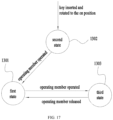
- a riding lawn mower including: a seat for a user to sit thereon; a chassis configured to support the seat; a cutting assembly mounted to the chassis, the cutting assembly including a cutting member for cutting grass; a walking assembly configured to drive the riding lawn mower to walk on a plane; a motor for driving the walking assembly; a steering wheel assembly, including a steering wheel operable by the user; wherein the riding lawn mower further includes: a control circuit configured to control the motor, the control circuit having a first state that permits the motor to rotate and a second state that prevents the motor from rotating; and an operating member operable to switch the control circuit into the first state; the operating member is mounted to the steering wheel.
- control circuit further has a third state, in which the control circuit stops the motor and then permits the motor to rotate reversely, and the operating member operable to switch the control circuit into the third state.
- the operating member is at least one paddle shifter; when the control circuit is in the second state and the at least one paddle shifter is pressed, the control circuit is switched into the first state.
- control circuit when the control circuit is in the first state and the at least one paddle shifter remains pressed for a time period greater than or equal to a first time threshold, the control circuit is switched into the third state.
- the control circuit determines if a rotational speed of the motor is less than or equal to a first velocity threshold, and if the rotational speed of the motor is less than or equal to the first velocity threshold, the control circuit is switched into the third state.
- control circuit when the control circuit is in the third state and the at least one paddle shifter is released, the control circuit is switched into the first state.
- a maximum rotational speed of the motor when the control circuit is in the third state is less than a maximum rotational speed of the motor when the control circuit is in the first state.
- an acceleration of the control circuit switching from the first state to the third state varies across the plurality of driving modes.
- the screen layer is an LCD screen or an LED screen.
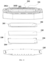
- the thickness of the cover layer 1382 is greater than or equal to 2mm and less than or equal to 5mm. Or, the thickness of the cover layer 1382 is greater than or equal to 3mm and less than or equal to 4mm. In one embodiment, the thickness of the cover layer 1382 is 3.5mm. As the cover layer 1382 in this disclosure is made relatively thick, the cover layer 1382 is less prone to deformation, bending or dent. As a result, the distance D7 between the cover layer 1382 and the screen layer 1830, specifically, the distance D7 between the cover layer 1382 and the middle layer 1383, i.e., the height of the first chamber 2013, can be made relatively small.
- the distance D7 between the cover layer 1382 and the screen layer 1830 may be greater than or equal to 0.1mm and less than or equal to 3mm. Or, the distance D7 between the cover layer 1382 and the screen layer 1830may be greater than or equal to 0.2mm and less than or equal to 2mm. In one embodiment, the distance D7 between the cover layer 1382 and the screen layer 1830 is 0.3mm.
- the first seal can still seal the first chamber; if the first seal breaks and the second seal still functions, the second seal can still seal the space of the first chamber plus the second chamber.
- the first chamber 2013 and the second chamber 2014 play a role in force balancing.
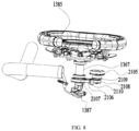
- the display interface 138 may not include a screen layer 1380. That is, the display interface 138 does not have an LED screen or an LCD screen. Instead, as shown in FIG. 16 , the display interface 138 includes a casing 1381 and a printed circuit board 1385 accommodated in the casing 1381.
- the casing 1381 may be made of tempered glass or polycarbonate (PC) materials, and the thickness of the casing 1381 is greater than 2mm and less than or equal to 5mm.
- the printed circuit board has a plurality of light-emitting elements 1388, such as LED lamp beads.
- the display interface 138 further includes a light-guiding layer 1389 engraved with light-guiding channels.
- the light-guiding layer 1389 may be a separate part or formed integrally with the casing 1381 as one piece.
- a sticker (not shown) may be adhered to the casing 1381 or the light-guiding layer 1388 to further improve the display effect.
- flexible adhesives are applied between the printed circuit board 1385 and the casing 1381 to seal a chamber at least including a space between the printed circuit board 1385 and the casing 1381.
- the independently sealed display interface 138 can then be assembled to a variety of gardening tools or power tools.
- the base plate 1386 has a double D hole
- the fixing plate 1369 also has a double D hole
- the rotary shaft 1367 has a double D portion which fits in the double D hole of the fixing plate 1369 and the base plate 1386.
- the rotary shaft 1367 is welded to the fixing plate 1369, thereby forming synchronous rotation with the fixing plate 1369. This structure ensures the stable connection between the rotary shaft 1367 and the steering wheel 1362.
- the steering wheel assembly 136 includes an adjustment device operable to adjust the height of the steering wheel 1362.
- the adjustment device enables at least one of the supporting member 1365 and the mounting box 1364 to move in the up and down direction with respect to the connecting rod 1361, while the position of the adjustment device is fixed with respect to the connecting rod 1361.
- the supporting member 1365 is formed in the shape of a cylinder, and the adjustment device is enabled to fix to different positions of the cylinder. When the adjustment device is fixed to a lower position of the cylinder, the height of the steering wheel 1362 is relatively high; when the adjustment device is fixed to a higher position of the cylinder, the height of the steering wheel 1362 is relatively low.
- the rotary shaft 1367 has a through hole, which allows a cable, or wire, to pass through the through hole.
- One end of the cable is connected to a first circuit board 1387, and the other end of the cable is connected to a second circuit board.
- the second circuit board is the printed circuit board 1385 of the display interface 138.
- the wire 1393 of the switch 1391 coupled with the operating member 139 is connected to the printed circuit board 1385 to reduce the number of wires.
- the at least one fastener realizes both functions of mounting the supporting member 1365 to the mounting box 1364 and limiting the position of the stopper projection 2103, so as to limit the angle of rotation of the steering wheel 1362. Further, the at least one fastener is firm, durable, low cost, and replaceable easily. In other embodiments, however, the matching projection 2104 is not a fastener; in fact, the matching projection 2104 may be any protruding structure that is configured to limit the rotational position of the stopper projection 2103.
- the steering wheel 1362 has a first limit position 2111 when rotating clockwise about the first axis, as shown in FIG. 12A and a second limit position 2112 when rotating counterclockwise about the first axis, as shown in FIG. 12B .
- the angle that the steering wheel 136 rotates from the first limit position 2111 to the second limit position 2112 is less than or equal to 380 degrees. In one embodiment, the angle that the steering wheel 136 rotates from the first limit position 2111 to the second limit position 2112 is less than or equal to 320 degrees. In one embodiment, the angle that the steering wheel 136 rotates from the first limit position 2111 to the second limit position 2112 is less than or equal to 240 degrees.
- the angle that the steering wheel 136 rotates from the first limit position 2111 to the second limit position 2112 is 270 degrees.
- the steering wheel 1362 is configured to rotate clockwise and counterclockwise for the same degrees, the angle that the steering wheel 136 rotates from the first limit position 2111 to the second limit position 2112 can split equally.
- the steering wheel 1362 further has an initial position 2113, in which the steering wheel 1362 is symmetrical about the second axis 108.
- the angle ⁇ l that the steering wheel 136 rotates from the initial position 2113 to the first limit position 2111 is less than or equal to 190 degrees
- the angle ⁇ 2 that the steering wheel 136 rotates from the initial position 2113 to the second limit position 2112 is less than or equal to 190 degrees
- the angle ⁇ l that the steering wheel 136 rotates from the initial position 2113 to the first limit position 2111 is less than or equal to 160 degrees
- the angle ⁇ 2 that the steering wheel 136 rotates from the initial position 2113 to the second limit position 2112 is less than or equal to 160 degrees.
- the angle ⁇ 1 that the steering wheel 136 rotates from the initial position 2113 to the first limit position 2111 is less than or equal to 120 degrees
- the angle ⁇ 2 that the steering wheel 136 rotates from the initial position 2113 to the second limit position 2112 is less than or equal to 120 degrees.
- the angle ⁇ l that the steering wheel 136 rotates from the initial position 2113 to the first limit position 2111 is 135 degrees
- the angle ⁇ 2 that the steering wheel 136 rotates from the initial position 2113 to the second limit position 2112 is 135 degrees.
- the steering wheel assembly 136 further includes a damper 2105, and the rotary shaft 1367 and the damper 2105 transmit force through a belt drive.
- the damper 2105 is a rotary damper, or called disk damper.
- the rotary shaft 1367 is coupled with a gearwheel 2107.
- the gearwheel 2107 has a double D hole, which fits in a double D portion of the rotary shaft 1367.
- the damper 2105 is also coupled with a gear 2108.
- the damper 2105 has a shaft 2109, and the gear 2108 is fixed to the shaft 2109 of the damper 2105.
- the gearwheel 2107 and the gear 2108 are both engaged with a belt 2106.
- the belt 2106 transmits force from the gearwheel 2107 to the gear 2108 and from the gear 2108 to the gearwheel 2107.
- the rotary shaft 1367 rotates, causing the gearwheel 2107 to rotate.
- the gearwheel 2107 rotates, the belt rotates and passes the rotary force to the gear 2108 and the shaft.
- the shaft rotates, the viscosity of the sealed oil in the damper's body will create resistance to the movement of the shaft 2109. This resistance (or called viscous friction) will slow down the movement speed of the steering wheel 1362.
- the damper 2105 moves, its torque is generally influenced by the viscosity of the sealed oil.
- the belt 2106 is further provided with a tension device 2110.
- at least part of the damper 2105 and the belt drive is accommodated inside the supporting member 1365, which provides better fixation and protection. It is noted that, the specific structure of the damper 2105 is not limited herein; and in some embodiments, the damper 2105 can be replaced by a motor to provide damping effect.
- the angular position of the steering wheel 1362 can be calculated from the rotational position of the motor and the transmission ratio of the belt drive, thereby eliminating the need for extra sensors for detecting the angular position of the steering wheel 1362.
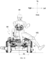
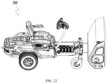
- aspects of this invention are also applicable to riding machines of other types, as long as the riding machine can output power in other forms besides walking power in order to realize other functions besides walking, for example, the riding snow blower 200 as shown in FIG. 22 also adopts the same or similar design of embodiments described above.
Landscapes
- Life Sciences & Earth Sciences (AREA)
- Environmental Sciences (AREA)
- Engineering & Computer Science (AREA)
- Chemical & Material Sciences (AREA)
- Combustion & Propulsion (AREA)
- Transportation (AREA)
- Mechanical Engineering (AREA)
- Harvester Elements (AREA)
Claims (8)
- Ein Aufsitzrasenmäher (100), umfassend:einen Sitz (15), auf dem ein Benutzer sitzen kann;ein Fahrgestell (16), das so konfiguriert ist, den Sitz zu tragen;eine Schneidvorrichtung (11), die am Fahrgestell (16) montiert ist, wobei die Schneidvorrichtung (11) ein Schneidelement (111) zum Schneiden von Gras umfasst;eine Geh-Vorrichtung (12), die so konfiguriert ist, den Aufsitzrasenmäher (100) auf einer Ebene zu bewegen;einen Elektromotor (123) zum Antreiben der Geh-Vorrichtung (12);einen Startknopf (133); undeine Lenkradvorrichtung (136), die ein vom Benutzer bedienbares Lenkrad (1362) und eine Verbindungsstange (1361) umfasst, die das Lenkrad (1362) mit dem Fahrgestell (16) verbindet;wobei die Lenkradvorrichtung (136) ferner umfasst:eine Montagevorrichtung, die das Lenkrad (1362) und die Verbindungsstange (1361) verbindet;eine Steuerschaltung mit einem ersten Zustand, der den Motor (123) starten lässt, und einem zweiten Zustand, der das Starten des Motors (123) verhindert;wobei der Aufsitzrasenmäher (100) dadurch gekennzeichnet ist, dass er ferner umfasst:ein Bedienelement (139), das betätigt werden kann, um die Steuerschaltung in den ersten Zustand zu versetzen;wobei das Bedienelement (139) am Lenkrad (1362) oder an der Montagevorrichtung angebracht ist,wobei das Bedienelement (139) mit einem Schalter (1391) gekoppelt ist und das Bedienelement (139) so betätigt werden kann, dass es den Schalter (1391) aktiviert,wobei, wenn der Startknopf (133) gedrückt wird und der Schalter (1391) durch das Bedienelement (139) aktiviert wird, die Steuerschaltung in den ersten Zustand versetzt wird.
- Der Aufsitzrasenmäher (100) nach Anspruch 1, wobei, wenn der Schalter (1391) durch das Bedienelement (139) aktiviert wird, die Steuerschaltung in den ersten Zustand versetzt wird.
- Der Aufsitzrasenmäher (100) nach Anspruch 1, wobei das Bedienelement (139) mindestens eine Schaltwippe (139L, 139R) ist.
- Der Aufsitzrasenmäher (100) nach Anspruch 3, wobei, wenn der Benutzer das Lenkrad (1362) mit einer Hand hält, die Schaltwippe (139L, 139R) durch mindestens einen Finger der Hand betätigt werden kann.
- Der Aufsitzrasenmäher (100) nach Anspruch 1, wobei das Bedienelement (139) ein Paar Schaltwippen (139L, 139R) ist, wobei das Paar Schaltwippen (139L, 139R) eine linke Schaltwippe (139L) und eine rechte Schaltwippe (139R) umfasst.
- Der Aufsitzrasenmäher (100) nach Anspruch 5, wobei, wenn der Benutzer das Lenkrad (1362) mit beiden Händen hält, die linke Schaltwippe (139L) durch mindestens einen Finger der linken Hand und die rechte Schaltwippe (139R) durch mindestens einen Finger der rechten Hand betätigt werden kann.
- Der Aufsitzrasenmäher (100) nach Anspruch 1, wobei die Lenkradvorrichtung (136) ferner eine Anzeigeoberfläche (138) umfasst, wobei die Anzeigeoberfläche (138) eine Leiterplatte (1385) aufweist und ein Draht (1393) des Schalters (1391) elektrisch mit der Leiterplatte verbunden ist.
- Der Aufsitzrasenmäher (100) nach Anspruch 1, wobei die Geh-Vorrichtung (12) mindestens ein erstes Lauf-Rad (121) und mindestens ein zweites Lauf-Rad (122) umfasst, wobei das zweite Lauf-Rad (122) vom Motor (123) angetrieben wird und das erste Lauf-Rad (121) frei drehbar ist.
Priority Applications (1)
| Application Number | Priority Date | Filing Date | Title |
|---|---|---|---|
| EP25156406.8A EP4527177A3 (de) | 2021-09-18 | 2021-09-18 | Aufsitzrasenmäher, anzeigeschnittstelle eines elektrowerkzeugs und aufsitzmaschine |
Applications Claiming Priority (1)
| Application Number | Priority Date | Filing Date | Title |
|---|---|---|---|
| PCT/CN2021/119302 WO2023039874A1 (en) | 2021-09-18 | 2021-09-18 | Riding lawn mower, display interface of a power tool and riding machine |
Related Child Applications (1)
| Application Number | Title | Priority Date | Filing Date |
|---|---|---|---|
| EP25156406.8A Division EP4527177A3 (de) | 2021-09-18 | 2021-09-18 | Aufsitzrasenmäher, anzeigeschnittstelle eines elektrowerkzeugs und aufsitzmaschine |
Publications (3)
| Publication Number | Publication Date |
|---|---|
| EP4231813A1 EP4231813A1 (de) | 2023-08-30 |
| EP4231813A4 EP4231813A4 (de) | 2024-01-24 |
| EP4231813B1 true EP4231813B1 (de) | 2025-02-26 |
Family
ID=85602353
Family Applications (2)
| Application Number | Title | Priority Date | Filing Date |
|---|---|---|---|
| EP21957152.8A Active EP4231813B1 (de) | 2021-09-18 | 2021-09-18 | Aufsitzrasenmäher |
| EP25156406.8A Pending EP4527177A3 (de) | 2021-09-18 | 2021-09-18 | Aufsitzrasenmäher, anzeigeschnittstelle eines elektrowerkzeugs und aufsitzmaschine |
Family Applications After (1)
| Application Number | Title | Priority Date | Filing Date |
|---|---|---|---|
| EP25156406.8A Pending EP4527177A3 (de) | 2021-09-18 | 2021-09-18 | Aufsitzrasenmäher, anzeigeschnittstelle eines elektrowerkzeugs und aufsitzmaschine |
Country Status (4)
| Country | Link |
|---|---|
| US (2) | US12035654B2 (de) |
| EP (2) | EP4231813B1 (de) |
| CN (2) | CN117202775A (de) |
| WO (1) | WO2023039874A1 (de) |
Families Citing this family (3)
| Publication number | Priority date | Publication date | Assignee | Title |
|---|---|---|---|---|
| WO2022075206A1 (ja) * | 2020-10-05 | 2022-04-14 | 株式会社クボタ | 電動トラクタ |
| CN119054491A (zh) * | 2023-06-02 | 2024-12-03 | 苏州宝时得电动工具有限公司 | 骑乘式割草机 |
| CN121420778A (zh) * | 2024-07-23 | 2026-01-30 | 南京泉峰科技有限公司 | 骑乘式割草机 |
Family Cites Families (72)
| Publication number | Priority date | Publication date | Assignee | Title |
|---|---|---|---|---|
| US3561282A (en) * | 1970-02-05 | 1971-02-09 | Int Harvester Co | Adjustable angle steering wheel mechanism for riding mower |
| US3732671A (en) * | 1971-08-31 | 1973-05-15 | Deere & Co | Electric drive riding mower |
| US5406778A (en) * | 1994-02-03 | 1995-04-18 | Ransomes America Corporation | Electric drive riding greens mower |
| US5713189A (en) | 1995-08-16 | 1998-02-03 | Ransomes America Corporation | Interactive brake system for electric riding mower |
| US5865016A (en) * | 1997-02-07 | 1999-02-02 | Ransomes America Corporation | Release mechanism for cutting head of a gang mower |
| US6092617A (en) | 1998-02-17 | 2000-07-25 | The Toro Company | System for automatically slowing vehicle during turns |
| WO1999062323A1 (en) | 1998-06-05 | 1999-12-09 | Mtd Products Inc. | Cruise control system |
| AU2003200523B2 (en) | 1998-08-17 | 2004-09-02 | Ransomes America Corporation | Electric drive mower |
| DE10229350A1 (de) | 2002-06-29 | 2004-01-15 | Dr. Johannes Heidenhain Gmbh | Verfahren zum Betätigen einer Haltebremse |
| US6997281B2 (en) * | 2002-11-26 | 2006-02-14 | General Motors Corporation | Driver control input device for drive-by-wire vehicle |
| JP4270079B2 (ja) | 2003-09-05 | 2009-05-27 | 日産自動車株式会社 | 駆動力制御装置 |
| JP4605649B2 (ja) | 2005-03-22 | 2011-01-05 | 株式会社クボタ | 草刈り機 |
| JP5119646B2 (ja) | 2006-03-06 | 2013-01-16 | 株式会社アドヴィックス | 車両用ブレーキ制御装置 |
| US20070295545A1 (en) | 2006-05-11 | 2007-12-27 | Romig Bernard E | Differential Steering and Traction Control For Electrically Propelled Mower |
| US20120159916A1 (en) | 2007-01-15 | 2012-06-28 | Kanzaki Kokyukoki Manufacturing Co., Ltd. | Control sysytem for motor-driven lawnmower vehicle |
| EP1943894B1 (de) | 2007-01-15 | 2010-05-19 | Kanzaki Kokyukoki Mfg. Co., Ltd. | Rasenmäher |
| US8207693B2 (en) | 2007-09-11 | 2012-06-26 | Hydro-Gear Limited Partnership | Controller assemblies for electric drive utility vehicles |
| US8011678B1 (en) * | 2007-09-20 | 2011-09-06 | Hydro-Gear Limited Partnership | Steering system for a zero-turn radius vehicle |
| JP2009078713A (ja) * | 2007-09-26 | 2009-04-16 | Honda Motor Co Ltd | 車両のスタート補助システム |
| US7894957B2 (en) | 2008-01-28 | 2011-02-22 | Textron Innovations Inc. | Dynamic tactical steering feedback |
| US7839106B2 (en) | 2008-03-05 | 2010-11-23 | Gm Global Technology Operations, Inc. | System and methods involving dynamic closed loop motor control and flux weakening |
| US7669580B2 (en) | 2008-03-24 | 2010-03-02 | Deere & Company | Electronic engine speed control system for grass mowing machine |
| US8544251B2 (en) * | 2008-06-27 | 2013-10-01 | The Toro Company | Reel mower with cutting units suspended by double A arm suspensions |
| FR2940881B1 (fr) | 2009-01-09 | 2011-01-21 | Etesia | Tondeuse electrique a conducteur porte et a alimentation autonome en fonctionnement |
| WO2010140929A1 (en) * | 2009-06-01 | 2010-12-09 | Andersson, Jonas | Lawn mower |
| US9624890B2 (en) * | 2009-11-19 | 2017-04-18 | Briggs & Stratton Corporation | Push button starting system module for outdoor power equipment |
| JP5521941B2 (ja) | 2010-09-24 | 2014-06-18 | 株式会社Ihi | 乗用型芝刈り車両及びその制御方法 |
| CN201941824U (zh) * | 2010-10-16 | 2011-08-24 | 合肥华信电动科技发展有限公司 | 电动车方向盘的旋钮开关 |
| JP5805437B2 (ja) * | 2011-06-14 | 2015-11-04 | 株式会社マキタ | 電動芝刈機 |
| US8838311B2 (en) | 2011-06-15 | 2014-09-16 | Kubota Corporation | Vehicle having independently driven and controlled right and left drive wheels |
| JP5933296B2 (ja) | 2011-07-29 | 2016-06-08 | 株式会社クボタ | 車両用変速制御システム |
| US9679419B2 (en) * | 2011-10-28 | 2017-06-13 | Husqvarna Ab | Indicator system for outdoor power equipment |
| CA2888220C (en) * | 2012-10-17 | 2017-01-17 | Husqvarna Ab | Smart ignition system |
| JP5648672B2 (ja) * | 2012-12-06 | 2015-01-07 | 井関農機株式会社 | 草刈機 |
| CN203410502U (zh) * | 2013-07-11 | 2014-01-29 | 上海格锐思实业有限公司 | 电动车舵式方向盘 |
| WO2015040987A1 (ja) | 2013-09-19 | 2015-03-26 | 日立工機株式会社 | 自走式草刈機 |
| CN104509297B (zh) * | 2013-09-30 | 2016-11-23 | 苏州宝时得电动工具有限公司 | 方向盘可调节的割草机 |
| CN104554255A (zh) | 2013-10-22 | 2015-04-29 | 沈阳工业大学 | 四轮全驱电动汽车底盘主动安全集成控制系统动态解耦方法 |
| JP6321970B2 (ja) | 2014-01-20 | 2018-05-09 | 株式会社クボタ | 芝刈機 |
| US20150308569A1 (en) | 2014-04-29 | 2015-10-29 | Parker-Hannifin Corporation | Controller and system for utility vehicle |
| CN104166372B (zh) | 2014-07-31 | 2017-04-05 | 西安交通大学苏州研究院 | 一种进给系统双位置环反馈的抗扰控制器 |
| US9616893B2 (en) | 2014-10-15 | 2017-04-11 | Honda Motor Co., Ltd. | Automatic turn-sensing ground speed reduction systems and related methods for walk-behind machines |
| US10058031B1 (en) | 2015-02-28 | 2018-08-28 | Hydro-Gear Limited Partnership | Lawn tractor with electronic drive and control system |
| JP6487827B2 (ja) | 2015-11-17 | 2019-03-20 | ヤンマー株式会社 | 作業車両 |
| CN105383544B (zh) * | 2015-11-25 | 2018-08-28 | 北京汽车股份有限公司 | 方向盘组件及汽车 |
| CN205454604U (zh) | 2016-01-22 | 2016-08-17 | 扬州维邦园林机械有限公司 | 一种电池动力草坪车 |
| JP6305453B2 (ja) | 2016-03-18 | 2018-04-04 | 本田技研工業株式会社 | 作業機 |
| US10394233B2 (en) * | 2016-05-20 | 2019-08-27 | Radio Flyer Inc. | Dual-controlled ride-on vehicle |
| JP2018102196A (ja) * | 2016-12-26 | 2018-07-05 | 本田技研工業株式会社 | 芝刈機 |
| US10356977B2 (en) | 2017-06-13 | 2019-07-23 | Deere + Company | Electric walk behind greens mower |
| JP6834837B2 (ja) | 2017-08-03 | 2021-02-24 | 井関農機株式会社 | 乗用芝刈り機 |
| WO2019035021A1 (en) * | 2017-08-16 | 2019-02-21 | Briggs & Stratton Corporation | NOZZLE ROLLING GUN MOWER HAVING FRONT AND REAR WHEELS RELATED IN RELATION TO A SINGLE PIVOT AXIS |
| CN107521456A (zh) * | 2017-09-29 | 2017-12-29 | 深圳市京弘全智能科技股份有限公司 | 一种具有自动识别功能的车辆启动装置 |
| JP6851504B2 (ja) | 2017-12-28 | 2021-03-31 | 三菱電機株式会社 | 電気車制御装置 |
| CN110313296B (zh) | 2018-03-28 | 2022-01-04 | 南京德朔实业有限公司 | 骑乘式割草机的操作装置以及骑乘式割草机 |
| CN111492783B (zh) | 2019-01-30 | 2023-09-12 | 南京泉峰科技有限公司 | 骑乘式草坪护理车 |
| US11785885B2 (en) * | 2019-01-31 | 2023-10-17 | The Toro Company | Mower with ganged reel cutting units having automatic clip control in both straight ahead motion and in turns |
| CN111756280A (zh) | 2019-03-28 | 2020-10-09 | 南京德朔实业有限公司 | 骑乘式割草机 |
| WO2020253821A1 (zh) | 2019-06-21 | 2020-12-24 | 南京德朔实业有限公司 | 骑乘式割草机 |
| CN211171513U (zh) | 2019-07-08 | 2020-08-04 | 青岛科泰重工机械有限公司 | 胶轮压路机的操控装置 |
| US11067326B2 (en) * | 2019-07-08 | 2021-07-20 | Haier Us Appliance Solutions, Inc. | Ice dispensing assemblies and methods for preventing clumping |
| WO2021004484A1 (zh) * | 2019-07-09 | 2021-01-14 | 南京德朔实业有限公司 | 骑乘式割草机及其控制方法 |
| CN210671321U (zh) | 2019-09-03 | 2020-06-05 | 绿友机械集团股份有限公司 | 一种坐骑式电动零转弯割草机 |
| CN110677079B (zh) | 2019-09-04 | 2021-02-26 | 深圳市百盛传动有限公司 | 一种永磁同步电机速度控制模式扰动观测器 |
| CN112740893B (zh) | 2019-10-29 | 2023-09-08 | 南京泉峰科技有限公司 | 骑乘式割草机 |
| CN211210526U (zh) * | 2019-11-04 | 2020-08-11 | 厦门纵横通电动车有限公司 | 一种新型电动割草机 |
| CN110989578B (zh) | 2019-11-15 | 2023-08-01 | 苏州博迷科技有限公司 | 一种可无线控制的双核四轮驱动uwb定位割草机器人及其控制方法 |
| CN110741810B (zh) * | 2019-12-09 | 2024-11-12 | 重庆大江动力设备制造有限公司 | 一种坐骑式割草机 |
| CN211793024U (zh) * | 2019-12-09 | 2020-10-30 | 重庆大江动力设备制造有限公司 | 一种坐骑式割草机 |
| CN111516747B (zh) * | 2020-03-25 | 2021-04-23 | 浙江中坚科技股份有限公司 | 零转角电动割草机的方向控制机构 |
| US12137625B2 (en) | 2021-03-15 | 2024-11-12 | Kubota Corporation | Work vehicle and control system for work vehicle |
| CN113243196A (zh) * | 2021-05-11 | 2021-08-13 | 绿友机械集团股份有限公司 | 一种电动驾乘式草坪修剪机的中排后集草刀盘 |
-
2021
- 2021-09-18 EP EP21957152.8A patent/EP4231813B1/de active Active
- 2021-09-18 CN CN202180091191.5A patent/CN117202775A/zh active Pending
- 2021-09-18 CN CN202511693026.3A patent/CN121369054A/zh active Pending
- 2021-09-18 WO PCT/CN2021/119302 patent/WO2023039874A1/en not_active Ceased
- 2021-09-18 EP EP25156406.8A patent/EP4527177A3/de active Pending
-
2023
- 2023-05-19 US US18/320,304 patent/US12035654B2/en active Active
-
2024
- 2024-06-11 US US18/740,179 patent/US12568880B2/en active Active
Also Published As
| Publication number | Publication date |
|---|---|
| US12035654B2 (en) | 2024-07-16 |
| US20230284560A1 (en) | 2023-09-14 |
| EP4231813A4 (de) | 2024-01-24 |
| EP4231813A1 (de) | 2023-08-30 |
| EP4527177A2 (de) | 2025-03-26 |
| US20240324501A1 (en) | 2024-10-03 |
| US12568880B2 (en) | 2026-03-10 |
| CN121369054A (zh) | 2026-01-23 |
| EP4527177A3 (de) | 2025-05-07 |
| CN117202775A (zh) | 2023-12-08 |
| WO2023039874A1 (en) | 2023-03-23 |
Similar Documents
| Publication | Publication Date | Title |
|---|---|---|
| US12035654B2 (en) | Riding lawn mower, display interface of a power tool and riding machine | |
| US11801882B2 (en) | Handcart | |
| US12103579B2 (en) | Working machine | |
| CA2728612A1 (en) | Model helicopter | |
| CN218634775U (zh) | 割草拖拉机 | |
| JP6699021B2 (ja) | 草刈機用の刈刃部 | |
| US7040791B2 (en) | Illumination apparatus having front and side illumination units | |
| US20240081178A1 (en) | Riding mowing device | |
| CN116114474A (zh) | 骑乘式割草设备 | |
| CN116114460A (zh) | 骑乘式割草设备 | |
| WO2023082770A1 (zh) | 骑乘式割草设备 | |
| US20260020519A1 (en) | Robot Control Method, Apparatus, Electronic Device and Storage Medium | |
| JP4055376B2 (ja) | 車両用アウターミラー | |
| JP4499368B2 (ja) | コンバイン | |
| CN116118915A (zh) | 骑乘式车辆 | |
| CN116114457B (zh) | 割草拖拉机 | |
| CN223844394U (zh) | 自主作业设备 | |
| CN219029297U (zh) | 一种屏幕调节机构及车辆 | |
| CN221784686U (zh) | 自主作业设备 | |
| CN117351617A (zh) | 电气设备 | |
| CN118923322A (zh) | 载人式割草机及全地形车 | |
| JPH1149492A (ja) | ピッキングフォークリフト | |
| JP2007001459A (ja) | 車両用フットレスト装置 | |
| KR20050047863A (ko) | 차량용 전동접힘 사이드 미러의 진동방지구조 | |
| JP2002238411A (ja) | 釣り用リールの表示装置 |
Legal Events
| Date | Code | Title | Description |
|---|---|---|---|
| STAA | Information on the status of an ep patent application or granted ep patent |
Free format text: STATUS: THE INTERNATIONAL PUBLICATION HAS BEEN MADE |
|
| PUAI | Public reference made under article 153(3) epc to a published international application that has entered the european phase |
Free format text: ORIGINAL CODE: 0009012 |
|
| STAA | Information on the status of an ep patent application or granted ep patent |
Free format text: STATUS: REQUEST FOR EXAMINATION WAS MADE |
|
| 17P | Request for examination filed |
Effective date: 20230526 |
|
| AK | Designated contracting states |
Kind code of ref document: A1 Designated state(s): AL AT BE BG CH CY CZ DE DK EE ES FI FR GB GR HR HU IE IS IT LI LT LU LV MC MK MT NL NO PL PT RO RS SE SI SK SM TR |
|
| REG | Reference to a national code |
Ref country code: DE Ref legal event code: R079 Free format text: PREVIOUS MAIN CLASS: A01D0034640000 Ipc: A01D0034820000 Ref country code: DE Ref legal event code: R079 Ref document number: 602021026964 Country of ref document: DE Free format text: PREVIOUS MAIN CLASS: A01D0034640000 Ipc: A01D0034820000 |
|
| A4 | Supplementary search report drawn up and despatched |
Effective date: 20240102 |
|
| RIC1 | Information provided on ipc code assigned before grant |
Ipc: A01D 34/69 20060101ALI20231219BHEP Ipc: A01D 34/68 20060101ALI20231219BHEP Ipc: A01D 34/64 20060101ALI20231219BHEP Ipc: A01D 34/82 20060101AFI20231219BHEP |
|
| RIC1 | Information provided on ipc code assigned before grant |
Ipc: A01D 34/69 20060101ALI20240905BHEP Ipc: A01D 34/68 20060101ALI20240905BHEP Ipc: A01D 34/64 20060101ALI20240905BHEP Ipc: A01D 34/82 20060101AFI20240905BHEP |
|
| GRAP | Despatch of communication of intention to grant a patent |
Free format text: ORIGINAL CODE: EPIDOSNIGR1 |
|
| STAA | Information on the status of an ep patent application or granted ep patent |
Free format text: STATUS: GRANT OF PATENT IS INTENDED |
|
| INTG | Intention to grant announced |
Effective date: 20241018 |
|
| DAV | Request for validation of the european patent (deleted) | ||
| DAX | Request for extension of the european patent (deleted) | ||
| GRAS | Grant fee paid |
Free format text: ORIGINAL CODE: EPIDOSNIGR3 |
|
| GRAA | (expected) grant |
Free format text: ORIGINAL CODE: 0009210 |
|
| STAA | Information on the status of an ep patent application or granted ep patent |
Free format text: STATUS: THE PATENT HAS BEEN GRANTED |
|
| AK | Designated contracting states |
Kind code of ref document: B1 Designated state(s): AL AT BE BG CH CY CZ DE DK EE ES FI FR GB GR HR HU IE IS IT LI LT LU LV MC MK MT NL NO PL PT RO RS SE SI SK SM TR |
|
| REG | Reference to a national code |
Ref country code: GB Ref legal event code: FG4D |
|
| REG | Reference to a national code |
Ref country code: CH Ref legal event code: EP |
|
| REG | Reference to a national code |
Ref country code: DE Ref legal event code: R096 Ref document number: 602021026964 Country of ref document: DE |
|
| REG | Reference to a national code |
Ref country code: IE Ref legal event code: FG4D |
|
| REG | Reference to a national code |
Ref country code: NL Ref legal event code: MP Effective date: 20250226 |
|
| PG25 | Lapsed in a contracting state [announced via postgrant information from national office to epo] |
Ref country code: RS Free format text: LAPSE BECAUSE OF FAILURE TO SUBMIT A TRANSLATION OF THE DESCRIPTION OR TO PAY THE FEE WITHIN THE PRESCRIBED TIME-LIMIT Effective date: 20250526 |
|
| PG25 | Lapsed in a contracting state [announced via postgrant information from national office to epo] |
Ref country code: FI Free format text: LAPSE BECAUSE OF FAILURE TO SUBMIT A TRANSLATION OF THE DESCRIPTION OR TO PAY THE FEE WITHIN THE PRESCRIBED TIME-LIMIT Effective date: 20250226 |
|
| PG25 | Lapsed in a contracting state [announced via postgrant information from national office to epo] |
Ref country code: PL Free format text: LAPSE BECAUSE OF FAILURE TO SUBMIT A TRANSLATION OF THE DESCRIPTION OR TO PAY THE FEE WITHIN THE PRESCRIBED TIME-LIMIT Effective date: 20250226 |
|
| PG25 | Lapsed in a contracting state [announced via postgrant information from national office to epo] |
Ref country code: ES Free format text: LAPSE BECAUSE OF FAILURE TO SUBMIT A TRANSLATION OF THE DESCRIPTION OR TO PAY THE FEE WITHIN THE PRESCRIBED TIME-LIMIT Effective date: 20250226 |
|
| REG | Reference to a national code |
Ref country code: LT Ref legal event code: MG9D |
|
| PG25 | Lapsed in a contracting state [announced via postgrant information from national office to epo] |
Ref country code: NO Free format text: LAPSE BECAUSE OF FAILURE TO SUBMIT A TRANSLATION OF THE DESCRIPTION OR TO PAY THE FEE WITHIN THE PRESCRIBED TIME-LIMIT Effective date: 20250526 Ref country code: IS Free format text: LAPSE BECAUSE OF FAILURE TO SUBMIT A TRANSLATION OF THE DESCRIPTION OR TO PAY THE FEE WITHIN THE PRESCRIBED TIME-LIMIT Effective date: 20250626 |
|
| PG25 | Lapsed in a contracting state [announced via postgrant information from national office to epo] |
Ref country code: NL Free format text: LAPSE BECAUSE OF FAILURE TO SUBMIT A TRANSLATION OF THE DESCRIPTION OR TO PAY THE FEE WITHIN THE PRESCRIBED TIME-LIMIT Effective date: 20250226 |
|
| PG25 | Lapsed in a contracting state [announced via postgrant information from national office to epo] |
Ref country code: HR Free format text: LAPSE BECAUSE OF FAILURE TO SUBMIT A TRANSLATION OF THE DESCRIPTION OR TO PAY THE FEE WITHIN THE PRESCRIBED TIME-LIMIT Effective date: 20250226 |
|
| PG25 | Lapsed in a contracting state [announced via postgrant information from national office to epo] |
Ref country code: PT Free format text: LAPSE BECAUSE OF FAILURE TO SUBMIT A TRANSLATION OF THE DESCRIPTION OR TO PAY THE FEE WITHIN THE PRESCRIBED TIME-LIMIT Effective date: 20250626 Ref country code: LV Free format text: LAPSE BECAUSE OF FAILURE TO SUBMIT A TRANSLATION OF THE DESCRIPTION OR TO PAY THE FEE WITHIN THE PRESCRIBED TIME-LIMIT Effective date: 20250226 |
|
| PG25 | Lapsed in a contracting state [announced via postgrant information from national office to epo] |
Ref country code: GR Free format text: LAPSE BECAUSE OF FAILURE TO SUBMIT A TRANSLATION OF THE DESCRIPTION OR TO PAY THE FEE WITHIN THE PRESCRIBED TIME-LIMIT Effective date: 20250527 Ref country code: BG Free format text: LAPSE BECAUSE OF FAILURE TO SUBMIT A TRANSLATION OF THE DESCRIPTION OR TO PAY THE FEE WITHIN THE PRESCRIBED TIME-LIMIT Effective date: 20250226 |
|
| REG | Reference to a national code |
Ref country code: AT Ref legal event code: MK05 Ref document number: 1769680 Country of ref document: AT Kind code of ref document: T Effective date: 20250226 |
|
| PG25 | Lapsed in a contracting state [announced via postgrant information from national office to epo] |
Ref country code: SE Free format text: LAPSE BECAUSE OF FAILURE TO SUBMIT A TRANSLATION OF THE DESCRIPTION OR TO PAY THE FEE WITHIN THE PRESCRIBED TIME-LIMIT Effective date: 20250226 |
|
| PG25 | Lapsed in a contracting state [announced via postgrant information from national office to epo] |
Ref country code: SM Free format text: LAPSE BECAUSE OF FAILURE TO SUBMIT A TRANSLATION OF THE DESCRIPTION OR TO PAY THE FEE WITHIN THE PRESCRIBED TIME-LIMIT Effective date: 20250226 |
|
| PG25 | Lapsed in a contracting state [announced via postgrant information from national office to epo] |
Ref country code: DK Free format text: LAPSE BECAUSE OF FAILURE TO SUBMIT A TRANSLATION OF THE DESCRIPTION OR TO PAY THE FEE WITHIN THE PRESCRIBED TIME-LIMIT Effective date: 20250226 |
|
| PGFP | Annual fee paid to national office [announced via postgrant information from national office to epo] |
Ref country code: DE Payment date: 20250730 Year of fee payment: 5 |
|
| PG25 | Lapsed in a contracting state [announced via postgrant information from national office to epo] |
Ref country code: IT Free format text: LAPSE BECAUSE OF FAILURE TO SUBMIT A TRANSLATION OF THE DESCRIPTION OR TO PAY THE FEE WITHIN THE PRESCRIBED TIME-LIMIT Effective date: 20250226 |
|
| PGFP | Annual fee paid to national office [announced via postgrant information from national office to epo] |
Ref country code: GB Payment date: 20250731 Year of fee payment: 5 |
|
| PG25 | Lapsed in a contracting state [announced via postgrant information from national office to epo] |
Ref country code: AT Free format text: LAPSE BECAUSE OF FAILURE TO SUBMIT A TRANSLATION OF THE DESCRIPTION OR TO PAY THE FEE WITHIN THE PRESCRIBED TIME-LIMIT Effective date: 20250226 |
|
| PGFP | Annual fee paid to national office [announced via postgrant information from national office to epo] |
Ref country code: FR Payment date: 20250808 Year of fee payment: 5 |
|
| PG25 | Lapsed in a contracting state [announced via postgrant information from national office to epo] |
Ref country code: EE Free format text: LAPSE BECAUSE OF FAILURE TO SUBMIT A TRANSLATION OF THE DESCRIPTION OR TO PAY THE FEE WITHIN THE PRESCRIBED TIME-LIMIT Effective date: 20250226 Ref country code: CZ Free format text: LAPSE BECAUSE OF FAILURE TO SUBMIT A TRANSLATION OF THE DESCRIPTION OR TO PAY THE FEE WITHIN THE PRESCRIBED TIME-LIMIT Effective date: 20250226 |
|
| PG25 | Lapsed in a contracting state [announced via postgrant information from national office to epo] |
Ref country code: RO Free format text: LAPSE BECAUSE OF FAILURE TO SUBMIT A TRANSLATION OF THE DESCRIPTION OR TO PAY THE FEE WITHIN THE PRESCRIBED TIME-LIMIT Effective date: 20250226 |
|
| PG25 | Lapsed in a contracting state [announced via postgrant information from national office to epo] |
Ref country code: SK Free format text: LAPSE BECAUSE OF FAILURE TO SUBMIT A TRANSLATION OF THE DESCRIPTION OR TO PAY THE FEE WITHIN THE PRESCRIBED TIME-LIMIT Effective date: 20250226 |
|
| REG | Reference to a national code |
Ref country code: DE Ref legal event code: R097 Ref document number: 602021026964 Country of ref document: DE |
|
| PLBE | No opposition filed within time limit |
Free format text: ORIGINAL CODE: 0009261 |
|
| STAA | Information on the status of an ep patent application or granted ep patent |
Free format text: STATUS: NO OPPOSITION FILED WITHIN TIME LIMIT |
|
| 26N | No opposition filed |
Effective date: 20251127 |