EP4459748A1 - Batterie und elektrische vorrichtung - Google Patents
Batterie und elektrische vorrichtung Download PDFInfo
- Publication number
- EP4459748A1 EP4459748A1 EP23755626.1A EP23755626A EP4459748A1 EP 4459748 A1 EP4459748 A1 EP 4459748A1 EP 23755626 A EP23755626 A EP 23755626A EP 4459748 A1 EP4459748 A1 EP 4459748A1
- Authority
- EP
- European Patent Office
- Prior art keywords
- battery
- thermally conductive
- battery according
- plate
- battery cell
- Prior art date
- Legal status (The legal status is an assumption and is not a legal conclusion. Google has not performed a legal analysis and makes no representation as to the accuracy of the status listed.)
- Pending
Links
Images


Classifications
-
- H—ELECTRICITY
- H01—ELECTRIC ELEMENTS
- H01M—PROCESSES OR MEANS, e.g. BATTERIES, FOR THE DIRECT CONVERSION OF CHEMICAL ENERGY INTO ELECTRICAL ENERGY
- H01M10/00—Secondary cells; Manufacture thereof
- H01M10/60—Heating or cooling; Temperature control
- H01M10/61—Types of temperature control
- H01M10/613—Cooling or keeping cold
-
- H—ELECTRICITY
- H01—ELECTRIC ELEMENTS
- H01M—PROCESSES OR MEANS, e.g. BATTERIES, FOR THE DIRECT CONVERSION OF CHEMICAL ENERGY INTO ELECTRICAL ENERGY
- H01M10/00—Secondary cells; Manufacture thereof
- H01M10/60—Heating or cooling; Temperature control
- H01M10/61—Types of temperature control
- H01M10/615—Heating or keeping warm
-
- H—ELECTRICITY
- H01—ELECTRIC ELEMENTS
- H01M—PROCESSES OR MEANS, e.g. BATTERIES, FOR THE DIRECT CONVERSION OF CHEMICAL ENERGY INTO ELECTRICAL ENERGY
- H01M10/00—Secondary cells; Manufacture thereof
- H01M10/60—Heating or cooling; Temperature control
- H01M10/62—Heating or cooling; Temperature control specially adapted for specific applications
- H01M10/625—Vehicles
-
- H—ELECTRICITY
- H01—ELECTRIC ELEMENTS
- H01M—PROCESSES OR MEANS, e.g. BATTERIES, FOR THE DIRECT CONVERSION OF CHEMICAL ENERGY INTO ELECTRICAL ENERGY
- H01M10/00—Secondary cells; Manufacture thereof
- H01M10/60—Heating or cooling; Temperature control
- H01M10/64—Heating or cooling; Temperature control characterised by the shape of the cells
- H01M10/647—Prismatic or flat cells, e.g. pouch cells
-
- H—ELECTRICITY
- H01—ELECTRIC ELEMENTS
- H01M—PROCESSES OR MEANS, e.g. BATTERIES, FOR THE DIRECT CONVERSION OF CHEMICAL ENERGY INTO ELECTRICAL ENERGY
- H01M10/00—Secondary cells; Manufacture thereof
- H01M10/60—Heating or cooling; Temperature control
- H01M10/65—Means for temperature control structurally associated with the cells
- H01M10/653—Means for temperature control structurally associated with the cells characterised by electrically insulating or thermally conductive materials
-
- H—ELECTRICITY
- H01—ELECTRIC ELEMENTS
- H01M—PROCESSES OR MEANS, e.g. BATTERIES, FOR THE DIRECT CONVERSION OF CHEMICAL ENERGY INTO ELECTRICAL ENERGY
- H01M10/00—Secondary cells; Manufacture thereof
- H01M10/60—Heating or cooling; Temperature control
- H01M10/65—Means for temperature control structurally associated with the cells
- H01M10/655—Solid structures for heat exchange or heat conduction
- H01M10/6554—Rods or plates
- H01M10/6555—Rods or plates arranged between the cells
-
- H—ELECTRICITY
- H01—ELECTRIC ELEMENTS
- H01M—PROCESSES OR MEANS, e.g. BATTERIES, FOR THE DIRECT CONVERSION OF CHEMICAL ENERGY INTO ELECTRICAL ENERGY
- H01M10/00—Secondary cells; Manufacture thereof
- H01M10/60—Heating or cooling; Temperature control
- H01M10/65—Means for temperature control structurally associated with the cells
- H01M10/655—Solid structures for heat exchange or heat conduction
- H01M10/6556—Solid parts with flow channel passages or pipes for heat exchange
- H01M10/6557—Solid parts with flow channel passages or pipes for heat exchange arranged between the cells
-
- H—ELECTRICITY
- H01—ELECTRIC ELEMENTS
- H01M—PROCESSES OR MEANS, e.g. BATTERIES, FOR THE DIRECT CONVERSION OF CHEMICAL ENERGY INTO ELECTRICAL ENERGY
- H01M10/00—Secondary cells; Manufacture thereof
- H01M10/60—Heating or cooling; Temperature control
- H01M10/65—Means for temperature control structurally associated with the cells
- H01M10/656—Means for temperature control structurally associated with the cells characterised by the type of heat-exchange fluid
- H01M10/6567—Liquids
- H01M10/6568—Liquids characterised by flow circuits, e.g. loops, located externally to the cells or cell casings
-
- H—ELECTRICITY
- H01—ELECTRIC ELEMENTS
- H01M—PROCESSES OR MEANS, e.g. BATTERIES, FOR THE DIRECT CONVERSION OF CHEMICAL ENERGY INTO ELECTRICAL ENERGY
- H01M10/00—Secondary cells; Manufacture thereof
- H01M10/60—Heating or cooling; Temperature control
- H01M10/65—Means for temperature control structurally associated with the cells
- H01M10/659—Means for temperature control structurally associated with the cells by heat storage or buffering, e.g. heat capacity or liquid-solid phase changes or transition
-
- H—ELECTRICITY
- H01—ELECTRIC ELEMENTS
- H01M—PROCESSES OR MEANS, e.g. BATTERIES, FOR THE DIRECT CONVERSION OF CHEMICAL ENERGY INTO ELECTRICAL ENERGY
- H01M4/00—Electrodes
- H01M4/02—Electrodes composed of, or comprising, active material
- H01M4/36—Selection of substances as active materials, active masses, active liquids
- H01M4/362—Composites
- H01M4/366—Composites as layered products
-
- H—ELECTRICITY
- H01—ELECTRIC ELEMENTS
- H01M—PROCESSES OR MEANS, e.g. BATTERIES, FOR THE DIRECT CONVERSION OF CHEMICAL ENERGY INTO ELECTRICAL ENERGY
- H01M4/00—Electrodes
- H01M4/02—Electrodes composed of, or comprising, active material
- H01M4/36—Selection of substances as active materials, active masses, active liquids
- H01M4/48—Selection of substances as active materials, active masses, active liquids of inorganic oxides or hydroxides
- H01M4/50—Selection of substances as active materials, active masses, active liquids of inorganic oxides or hydroxides of manganese
- H01M4/505—Selection of substances as active materials, active masses, active liquids of inorganic oxides or hydroxides of manganese of mixed oxides or hydroxides containing manganese for inserting or intercalating light metals, e.g. LiMn2O4 or LiMn2OxFy
-
- H—ELECTRICITY
- H01—ELECTRIC ELEMENTS
- H01M—PROCESSES OR MEANS, e.g. BATTERIES, FOR THE DIRECT CONVERSION OF CHEMICAL ENERGY INTO ELECTRICAL ENERGY
- H01M4/00—Electrodes
- H01M4/02—Electrodes composed of, or comprising, active material
- H01M4/36—Selection of substances as active materials, active masses, active liquids
- H01M4/48—Selection of substances as active materials, active masses, active liquids of inorganic oxides or hydroxides
- H01M4/52—Selection of substances as active materials, active masses, active liquids of inorganic oxides or hydroxides of nickel, cobalt or iron
- H01M4/525—Selection of substances as active materials, active masses, active liquids of inorganic oxides or hydroxides of nickel, cobalt or iron of mixed oxides or hydroxides containing iron, cobalt or nickel for inserting or intercalating light metals, e.g. LiNiO2, LiCoO2 or LiCoOxFy
-
- H—ELECTRICITY
- H01—ELECTRIC ELEMENTS
- H01M—PROCESSES OR MEANS, e.g. BATTERIES, FOR THE DIRECT CONVERSION OF CHEMICAL ENERGY INTO ELECTRICAL ENERGY
- H01M4/00—Electrodes
- H01M4/02—Electrodes composed of, or comprising, active material
- H01M4/36—Selection of substances as active materials, active masses, active liquids
- H01M4/58—Selection of substances as active materials, active masses, active liquids of inorganic compounds other than oxides or hydroxides, e.g. sulfides, selenides, tellurides, halogenides or LiCoFy; of polyanionic structures, e.g. phosphates, silicates or borates
- H01M4/5805—Phosphides
-
- H—ELECTRICITY
- H01—ELECTRIC ELEMENTS
- H01M—PROCESSES OR MEANS, e.g. BATTERIES, FOR THE DIRECT CONVERSION OF CHEMICAL ENERGY INTO ELECTRICAL ENERGY
- H01M4/00—Electrodes
- H01M4/02—Electrodes composed of, or comprising, active material
- H01M4/36—Selection of substances as active materials, active masses, active liquids
- H01M4/58—Selection of substances as active materials, active masses, active liquids of inorganic compounds other than oxides or hydroxides, e.g. sulfides, selenides, tellurides, halogenides or LiCoFy; of polyanionic structures, e.g. phosphates, silicates or borates
- H01M4/5825—Oxygenated metallic salts or polyanionic structures, e.g. borates, phosphates, silicates, olivines
-
- H—ELECTRICITY
- H01—ELECTRIC ELEMENTS
- H01M—PROCESSES OR MEANS, e.g. BATTERIES, FOR THE DIRECT CONVERSION OF CHEMICAL ENERGY INTO ELECTRICAL ENERGY
- H01M4/00—Electrodes
- H01M4/02—Electrodes composed of, or comprising, active material
- H01M4/62—Selection of inactive substances as ingredients for active masses, e.g. binders, fillers
- H01M4/621—Binders
- H01M4/622—Binders being polymers
-
- H—ELECTRICITY
- H01—ELECTRIC ELEMENTS
- H01M—PROCESSES OR MEANS, e.g. BATTERIES, FOR THE DIRECT CONVERSION OF CHEMICAL ENERGY INTO ELECTRICAL ENERGY
- H01M4/00—Electrodes
- H01M4/02—Electrodes composed of, or comprising, active material
- H01M4/62—Selection of inactive substances as ingredients for active masses, e.g. binders, fillers
- H01M4/624—Electric conductive fillers
- H01M4/626—Metals
-
- H—ELECTRICITY
- H01—ELECTRIC ELEMENTS
- H01M—PROCESSES OR MEANS, e.g. BATTERIES, FOR THE DIRECT CONVERSION OF CHEMICAL ENERGY INTO ELECTRICAL ENERGY
- H01M50/00—Constructional details or processes of manufacture of the non-active parts of electrochemical cells other than fuel cells, e.g. hybrid cells
- H01M50/10—Primary casings; Jackets or wrappings
- H01M50/102—Primary casings; Jackets or wrappings characterised by their shape or physical structure
- H01M50/103—Primary casings; Jackets or wrappings characterised by their shape or physical structure prismatic or rectangular
-
- H—ELECTRICITY
- H01—ELECTRIC ELEMENTS
- H01M—PROCESSES OR MEANS, e.g. BATTERIES, FOR THE DIRECT CONVERSION OF CHEMICAL ENERGY INTO ELECTRICAL ENERGY
- H01M50/00—Constructional details or processes of manufacture of the non-active parts of electrochemical cells other than fuel cells, e.g. hybrid cells
- H01M50/20—Mountings; Secondary casings or frames; Racks, modules or packs; Suspension devices; Shock absorbers; Transport or carrying devices; Holders
- H01M50/204—Racks, modules or packs for multiple batteries or multiple cells
- H01M50/207—Racks, modules or packs for multiple batteries or multiple cells characterised by their shape
- H01M50/209—Racks, modules or packs for multiple batteries or multiple cells characterised by their shape adapted for prismatic or rectangular cells
-
- H—ELECTRICITY
- H01—ELECTRIC ELEMENTS
- H01M—PROCESSES OR MEANS, e.g. BATTERIES, FOR THE DIRECT CONVERSION OF CHEMICAL ENERGY INTO ELECTRICAL ENERGY
- H01M50/00—Constructional details or processes of manufacture of the non-active parts of electrochemical cells other than fuel cells, e.g. hybrid cells
- H01M50/20—Mountings; Secondary casings or frames; Racks, modules or packs; Suspension devices; Shock absorbers; Transport or carrying devices; Holders
- H01M50/233—Mountings; Secondary casings or frames; Racks, modules or packs; Suspension devices; Shock absorbers; Transport or carrying devices; Holders characterised by physical properties of casings or racks, e.g. dimensions
- H01M50/242—Mountings; Secondary casings or frames; Racks, modules or packs; Suspension devices; Shock absorbers; Transport or carrying devices; Holders characterised by physical properties of casings or racks, e.g. dimensions adapted for protecting batteries against vibrations, collision impact or swelling
-
- H—ELECTRICITY
- H01—ELECTRIC ELEMENTS
- H01M—PROCESSES OR MEANS, e.g. BATTERIES, FOR THE DIRECT CONVERSION OF CHEMICAL ENERGY INTO ELECTRICAL ENERGY
- H01M50/00—Constructional details or processes of manufacture of the non-active parts of electrochemical cells other than fuel cells, e.g. hybrid cells
- H01M50/20—Mountings; Secondary casings or frames; Racks, modules or packs; Suspension devices; Shock absorbers; Transport or carrying devices; Holders
- H01M50/244—Secondary casings; Racks; Suspension devices; Carrying devices; Holders characterised by their mounting method
-
- H—ELECTRICITY
- H01—ELECTRIC ELEMENTS
- H01M—PROCESSES OR MEANS, e.g. BATTERIES, FOR THE DIRECT CONVERSION OF CHEMICAL ENERGY INTO ELECTRICAL ENERGY
- H01M50/00—Constructional details or processes of manufacture of the non-active parts of electrochemical cells other than fuel cells, e.g. hybrid cells
- H01M50/20—Mountings; Secondary casings or frames; Racks, modules or packs; Suspension devices; Shock absorbers; Transport or carrying devices; Holders
- H01M50/249—Mountings; Secondary casings or frames; Racks, modules or packs; Suspension devices; Shock absorbers; Transport or carrying devices; Holders specially adapted for aircraft or vehicles, e.g. cars or trains
-
- H—ELECTRICITY
- H01—ELECTRIC ELEMENTS
- H01M—PROCESSES OR MEANS, e.g. BATTERIES, FOR THE DIRECT CONVERSION OF CHEMICAL ENERGY INTO ELECTRICAL ENERGY
- H01M50/00—Constructional details or processes of manufacture of the non-active parts of electrochemical cells other than fuel cells, e.g. hybrid cells
- H01M50/30—Arrangements for facilitating escape of gases
- H01M50/342—Non-re-sealable arrangements
- H01M50/3425—Non-re-sealable arrangements in the form of rupturable membranes or weakened parts, e.g. pierced with the aid of a sharp member
-
- H—ELECTRICITY
- H01—ELECTRIC ELEMENTS
- H01M—PROCESSES OR MEANS, e.g. BATTERIES, FOR THE DIRECT CONVERSION OF CHEMICAL ENERGY INTO ELECTRICAL ENERGY
- H01M4/00—Electrodes
- H01M4/02—Electrodes composed of, or comprising, active material
- H01M2004/021—Physical characteristics, e.g. porosity, surface area
-
- H—ELECTRICITY
- H01—ELECTRIC ELEMENTS
- H01M—PROCESSES OR MEANS, e.g. BATTERIES, FOR THE DIRECT CONVERSION OF CHEMICAL ENERGY INTO ELECTRICAL ENERGY
- H01M4/00—Electrodes
- H01M4/02—Electrodes composed of, or comprising, active material
- H01M2004/026—Electrodes composed of, or comprising, active material characterised by the polarity
- H01M2004/028—Positive electrodes
-
- Y—GENERAL TAGGING OF NEW TECHNOLOGICAL DEVELOPMENTS; GENERAL TAGGING OF CROSS-SECTIONAL TECHNOLOGIES SPANNING OVER SEVERAL SECTIONS OF THE IPC; TECHNICAL SUBJECTS COVERED BY FORMER USPC CROSS-REFERENCE ART COLLECTIONS [XRACs] AND DIGESTS
- Y02—TECHNOLOGIES OR APPLICATIONS FOR MITIGATION OR ADAPTATION AGAINST CLIMATE CHANGE
- Y02E—REDUCTION OF GREENHOUSE GAS [GHG] EMISSIONS, RELATED TO ENERGY GENERATION, TRANSMISSION OR DISTRIBUTION
- Y02E60/00—Enabling technologies; Technologies with a potential or indirect contribution to GHG emissions mitigation
- Y02E60/10—Energy storage using batteries
Definitions
- the present application relates to the technical field of batteries, and particularly to a battery and an electrical apparatus.
- the energy density of a battery is an important parameter in the performance of the battery.
- it is also necessary to consider other properties of the battery, such as the energy density and thermal management performance of the battery. Therefore, how to improve the energy density of the battery and the thermal management performance of the battery is an urgent technical problem in battery technology.
- the present application is intended to solve at least one of the technical problems existing in the related art. To this end, the present application proposes a battery, which can effectively ensure heat conduction in the battery, can improve the thermal management performance of the battery and also can improve the energy density of the battery.
- the present application further proposes an electrical apparatus having the battery described above.
- a battery includes: a box having an accommodating cavity; at least two battery cells accommodated in the accommodating cavity, each of the battery cells comprises an electrode assembly and an electrode terminal, the electrode assembly is electrically connected with the electrode terminal, each of the battery cells comprises a first wall, the first wall is the wall with the largest area in the battery cell; a thermally conductive member for accommodating a heat exchange medium, the thermally conductive member is connected with the at least two battery cells, the thermally conductive member is arranged opposite to the first walls of the at least two battery cells, and the thermally conductive member is thermally conductively connected with the first walls of the at least two battery cells to utilize the heat exchange medium to adjust the temperature of the at least two battery cells.
- the battery of according to the embodiments of the present application there is no need to arrange beams and other structures in the boxes of the at least two battery cells, which can greatly improve the space utilization inside the battery, thus improving the energy density of the battery; at the same time, the heat conduction in the battery can be ensured by using the thermally conductive member, and the thermal management performance of the battery can be improved.
- each of the battery cells further includes a second wall connected with the first wall, and the first wall and the second wall intersect, and the electrode terminal is provided on the second wall.
- each of the battery cells includes two first walls arranged opposite to each other and two second walls arranged opposite to each other, and at least two electrode terminals are provided; and the at least two electrode terminals are provided on the same second wall; or each second wall is provided with at least one electrode terminal.
- the electrode terminal is provided on the first wall.
- the at least two battery cells are arranged in a first direction, each battery cell is provided with a first surface arranged opposite to the first wall in the first direction, the first surface is provided with an avoidance groove, and the avoidance groove of one of two adjacent battery cells is configured to accommodate the electrode terminal of the other battery cell, the first direction being perpendicular to the first wall.
- the first wall is formed in a cylindrical shape.
- second walls are provided at two axial ends of the first wall, and at least one of the second walls is provided with the electrode terminal.
- one of the second walls is provided with an electrode terminal that is exposed
- the electrode assembly includes the positive electrode plate and a negative electrode plate, one of the positive electrode plate and the negative electrode plate is electrically connected to the electrode terminal, and the other of the positive electrode plate and the negative electrode plate is electrically connected to the first wall or the other second wall.
- At least one battery cell is a pouch battery cell.
- each of the battery cells further includes a pressure relief mechanism, and the pressure relief mechanism and the electrode terminal are arranged on the same wall of the battery cell.
- each of the battery cells further includes a pressure relief mechanism, and the pressure relief mechanism and the electrode terminal are respectively arranged on two walls of the battery cell.
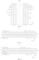
- the thermally conductive member is bonded to the first walls of the at least two battery cells via a first adhesive layer.
- the bottom of the thermally conductive member is bonded to a bottom wall of the accommodating cavity via a second adhesive layer; and/or the bottom of the thermally conductive member is bonded to a bottom wall of the accommodating cavity via a third adhesive layer.
- the thickness of the first adhesive layer is less than or equal to that of the second adhesive layer; and/or the thickness of the first adhesive layer is less than or equal to that of the third adhesive layer.
- the thermal conductivity of the first adhesive layer is greater than or equal to that of the second adhesive layer; and/or the thermal conductivity of the first adhesive layer is greater than or equal to that of the third adhesive layer.
- the ratio of the thickness of the first adhesive layer to the thermal conductivity of the first adhesive layer is defined as a first ratio
- the ratio of the thickness of the second adhesive layer to the thermal conductivity of the second adhesive layer is defined as a second ratio
- the ratio of the thickness of the third adhesive layer to the thermal conductivity of the third adhesive layer is defined as a third ratio; wherein the first ratio is less than or equal to the second ratio; and/or the first ratio is less than or equal to the third ratio.
- the thermally conductive member includes a metallic material and/or a non-metallic material.
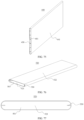
- the thermally conductive member includes a metal plate, and an insulating layer arranged on a surface of the metal plate; or the thermally conductive member is a plate of non-metallic material.
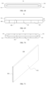
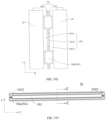
- the thermally conductive member includes a partition plate extending in the second direction and connected to the first wall of each of the plurality of battery cells, the second direction being parallel to the first wall.
- the thermally conductive member further includes an insulating layer configured to insulate and isolate the first wall of the battery cell from the partition plate.
- the thermal conductivity of the insulating layer is greater than or equal to 0.1 W/(m • K).
- a dimension T1 of the partition plate in a first direction is less than 0.5 mm, the first direction being perpendicular to the first wall.
- a dimension T1 of the partition plate in a first direction is greater than 5 mm, the first direction being perpendicular to the first wall.
- a surface of the thermally conductive member that is connected to the first wall is an insulating surface; and a dimension of the thermally conductive member in a first direction is 0.1-100 mm, the first direction being perpendicular to the first wall.
- a dimension H1 of the partition plate and a dimension H2 of the first wall satisfy: 0.1 ⁇ H1/H2 ⁇ 2, the third direction being perpendicular to the second direction and parallel to the first wall.
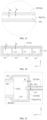
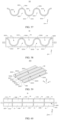
- the partition plate is internally provided with a hollow cavity.
- the hollow cavity is configured to accommodate a heat exchange medium to adjust the temperature of the battery cell.
- a dimension of the hollow cavity is W, and a capacity Q of the battery cell and the dimension W of the hollow cavity satisfy: 1.0 Ah/mm ⁇ Q/W ⁇ 400 Ah/mm, the first direction being perpendicular to the first wall.
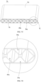
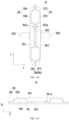
- the partition plate further includes a pair of thermally conductive plates arranged opposite to each other in a first direction, and the hollow cavity is provided between the pair of thermally conductive plates, the first direction being perpendicular to the first wall.
- the partition plate further includes a reinforcing rib arranged between the pair of thermally conductive plates.
- the reinforcing rib is connected to at least one of the pair of thermally conductive plates.
- the reinforcing rib includes a first reinforcing rib, two ends of the first reinforcing rib are respectively connected to the pair of thermally conductive plates, and the first reinforcing rib is arranged to be inclined relative to the first direction.
- an included angle between the first reinforcing rib and the first direction ranges from 30° to 60°.
- the reinforcing rib further includes a second reinforcing rib, one end of the second reinforcing rib is connected to one of the pair of thermally conductive plates, and the other end of the second reinforcing rib is arranged spaced apart from the other of the pair of thermally conductive plates.
- the second reinforcing rib extends in the first direction and protrudes from one of the pair of thermally conductive plates.
- the first reinforcing rib is arranged spaced apart from the second reinforcing rib.
- the thickness D of the thermally conductive plate and the dimension W of the hollow cavity satisfy: 0.01 ⁇ D/W ⁇ 25.
- the partition plate is provided with a medium inlet and a medium outlet, the hollow cavity is in communication with the medium inlet and the medium outlet, and the partition plate is internally provided with a chamber disconnected from both the medium inlet and the medium outlet.
- a partition member is provided in the hollow cavity, and is configured to divide the hollow cavity into at least two flow channels.
- the thermally conductive member includes a first thermally conductive plate, a second thermally conductive plate and the partition member which are arranged in a stacked manner, the partition member is arranged between the first thermally conductive plate and the second thermally conductive plate, the first thermally conductive plate and the partition member jointly define a first flow channel, and the second thermally conductive plate and the partition member jointly define a second flow channel.
- At least a part of the thermally conductive member is configured to be deformable when compressed.
- the thermally conductive member includes: a heat exchange layer and a compressible layer arranged in a stacked manner; and an elastic modulus of the compressible layer is less than an elastic modulus of the heat exchange layer.
- the compressible layer includes a compressible cavity filled with a phase change material or an elastic material.
- the thermally conductive member includes a shell and a supporting component, the supporting component is accommodated in the shell and configured to define a hollow cavity and a deformable cavity spaced apart from each other in the shell, the hollow cavity is configured for the flow of a heat exchange medium, and the deformable cavity is configured to be deformable when the shell is compressed.
- the thermally conductive member includes a shell and an isolation assembly, the isolation assembly is accommodated in the shell and connected to the shell so as to form a hollow cavity between the shell and the isolation assembly, the hollow cavity is configured for the flow of a heat exchange medium, and the isolation assembly is configured to be deformable when the shell is compressed.
- the thermally conductive member is provided with an avoidance structure configured to provide a space for expansion of the battery cell.
- a plurality of battery cells are provided, and at least a part of the avoidance structure is located between two adjacent battery cells and is configured to provide a space for expansion of at least one of the battery cells.
- the thermally conductive member in a first direction, includes a first thermally conductive plate and a second thermally conductive plate arranged opposite to each other, a hollow cavity is provided between the first thermally conductive plate and the second thermally conductive plate and is configured to accommodate a heat exchange medium, and at least one of the first thermally conductive plate and the second thermally conductive plate is recessed toward the other in the first direction to form the avoidance structure, the first direction being perpendicular to the first wall.
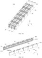
- two or more battery groups are provided in the box, and are arranged in a first direction, each of the battery groups includes two or more battery cells arranged in a second direction, the second direction is perpendicular to the first direction, and the first direction is perpendicular to the first wall.
- the thermally conductive member is sandwiched between two adjacent battery groups.
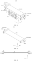
- the battery further includes a connecting pipe group, wherein a hollow cavity for accommodating a heat exchange medium is provided in the thermally conductive member, and the connecting pipe group is configured to communicate the hollow cavities of two or more thermally conductive members with each other.
- the connecting pipe group includes a communication channel, an inlet pipe and an outlet pipe, the hollow cavities of two adjacent thermally conductive members in the first direction are in communication with each other through the communication channel, and the inlet pipe and the outlet pipe are in communication with the hollow cavity of the same thermally conductive member.
- each of the battery cells further includes a battery casing
- the electrode assembly is accommodated in the battery casing
- the battery casing is provided with a pressure relief mechanism
- the pressure relief mechanism is integrally formed with the battery casing.
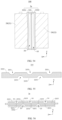
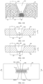
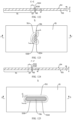
- the battery casing includes an integrally formed non-weak region and weak region, the battery casing is provided with a grooved portion, the non-weak region is formed around the grooved portion, the weak region is formed at the bottom of the grooved portion, the weak region is configured to be damaged when an internal pressure of the battery cell is released, and the pressure relief mechanism includes the weak region.
- an average grain size of the weak region is defined as S 1 and an average grain size of the non-weak region is defined as S 2 , satisfying: 0.05 ⁇ S 1 /S 2 ⁇ 0.9.
- the minimum thickness of the weak region is defined as A 1 and satisfies: 1 ⁇ A 1 /S 1 ⁇ 100.
- the minimum thickness of the weak region is defined as A 1 and the hardness of the weak region is defined as Bi, satisfying: 5 HBW/mm ⁇ B 1 /A 1 ⁇ 10000 HBW/mm.
- the hardness of the weak region is defined as Bi and the hardness of the non-weak region is defined as B 2 , satisfying: 1 ⁇ B 1 /B 2 ⁇ 5.
- the minimum thickness of the weak region is defined as A 1 and the minimum thickness of the non-weak region is defined as A 2 , satisfying: 0.05 ⁇ A 1 /A 2 ⁇ 0.95.
- the electrode assembly includes a positive electrode plate and a negative electrode plate
- the positive electrode plate and/or the negative electrode plate includes a current collector and an active material layer
- the current collector includes a supporting layer and a conductive layer
- the supporting layer is configured to carry the conductive layer
- the conductive layer is configured to carry the active material layer
- the conductive layer is arranged on at least one side of the supporting layer in a thickness direction of the supporting layer.
- a room temperature film resistance Rs of the conductive layer satisfies: 0.016 ⁇ / ⁇ ⁇ Rs ⁇ 420 ⁇ / ⁇ .
- the conductive layer is made of at least one material selected from aluminum, copper, titanium, silver, a nickel-copper alloy, and an aluminum-zirconium alloy.
- the material of the supporting layer includes one or more of a polymer material and a polymer-based composite material.
- the thickness d1 of the supporting layer and the light transmittance k of the supporting layer satisfy: when 12 ⁇ m ⁇ d1 ⁇ 30 ⁇ m, 30% ⁇ k ⁇ 80%; or when 8 ⁇ m ⁇ d1 ⁇ 12 ⁇ m, 40% ⁇ k ⁇ 90%; or when 1 ⁇ m ⁇ d1 ⁇ 8 ⁇ m, 50% ⁇ k ⁇ 98%.
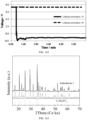
- the electrode assembly includes a positive electrode plate, the positive electrode plate includes a positive electrode current collector and a positive electrode active material layer coated on a surface of the positive electrode current collector, the positive electrode active material layer includes a positive electrode active material, and the positive electrode active material has an inner core and a shell coating the inner core, wherein the inner core includes at least one of a ternary material, dLi 2 MnO 3 ⁇ (1-d)LiMO 2 and LiMPO 4 , where 0 ⁇ d ⁇ 1, and the M includes one or more selected from Fe, Ni, Co, and Mn; and the shell contains an crystalline inorganic substance, the full width at half maximum of a main peak measured by X-ray diffraction of the crystalline inorganic substance is 0-3°, and the crystalline inorganic substance includes one or more selected from a metal oxide and an inorganic salt.
- the inner core includes at least one of a ternary material, dLi 2 MnO 3 ⁇ (1-d)Li
- the shell includes at least one of the metal oxide and the inorganic salt, and carbon.
- the electrode assembly includes a positive electrode plate, the positive electrode plate includes a positive electrode current collector and a positive electrode active material layer coated on a surface of the positive electrode current collector, the positive electrode active material layer includes a positive electrode active material, and the positive electrode active material has LiMPO 4 , where the M includes Mn, and a non-Mn element, and the non-Mn element satisfies at least one of the following conditions: an ionic radius of the non-Mn element is defined as a, an ionic radius of the manganese element is defined as b, and
- the non-Mn element includes one or both of a first doping element and a second doping element, the first doping element is doped at manganese site, and the second doping element is doped at a phosphorus site.
- the first doping element satisfies at least one of the following conditions: an ionic radius of the first doping element is defined as a, an ionic radius of the manganese element is defined as b, and
- the second doping element satisfies at least one of the following conditions: the chemical activity of a chemical bond formed by the second doping element and O is not less than the chemical activity of a P-O bond; and the highest valence of the second doping element is not greater than 6.
- the positive electrode active material further has a coating layer.
- the coating layer includes carbon
- the carbon in the coating layer is a mixture of SP2-form carbon and SP3-form carbon.
- a molar ratio of the SP2-form carbon to the SP3-form carbon is any value within a range of 0.1-10.
- an electrical apparatus includes a battery according to the embodiments in the first aspect of the present application, the battery being configured to supply electric energy.
- connection may be fixed connection, detachable connection or integrated connection, or may be direct connection, indirect connection through an intermediate, or internal communication of two elements.
- the term "and/or” is only an association relation describing associated objects, which means that there may be three relations, for example, A and/or B may represent three situations: A exists alone, both A and B exist, and B exists alone.
- the term “or” is inclusive in the present application.
- the phrase "A or B” means “A, B, or both A and B”; more specifically, the condition "A or B” is satisfied by any of the following: A is true (or present) and B is false (or absent); A is false (or absent) and B is true (or present); or both A and B are true (or present).
- the terms “including” and “comprising” mentioned in the present application may be open-ended, or may be closed-ended.
- the “including” and “comprising” may indicate that it is also possible to include or comprise other components not listed, and it is also possible to include or comprise only the listed components.
- Ranges disclosed in the present application are defined in the form of lower limits and upper limits, a given range is defined by the selection of a lower limit and an upper limit, and the selected lower limit and upper limit define boundaries of a particular range.
- a range defined in this manner may be inclusive or exclusive of end values, and may be arbitrarily combined, that is, any lower limit may be combined with any upper limit to form a range.
- Any lower limit can be combined with any upper limit to form a range not explicitly recited; and any lower limit can be combined with another lower limit to form a range not explicitly recited, and likewise, any upper limit can be combined with any another upper limit to form a range not explicitly recited.
- every point or single numerical value between the endpoints of a range is included within the range.
- each point or single numerical value may serve as its own lower or upper limit to form an unspecified range in combination with any other point or single numerical value or with other lower or upper limits.
- ranges of 60-120 and 80-110 are listed for a particular parameter, it is understood that the ranges of 60-110 and 80-120 are also contemplated. Additionally, if the minimum range values 1 and 2 are listed, and if the maximum range values 3, 4 and 5 are listed, the following ranges are all contemplated: 1-3, 1-4, 1-5, 2- 3, 2-4 and 2-5.
- the numerical range "a-b" represents an abbreviated representation of any combination of real numbers between a to b, where both a and b are real numbers.
- the numerical range "0-5" means that all the real numbers between "0-5" have been listed herein, and "0-5" is just an abbreviated representation of combinations of these numerical values.
- a parameter when a parameter is expressed as an integer greater than or equal to 2, it is equivalent to disclosing that the parameter is, for example, an integer of 2, 3, 4, 5, 6, 7, 8, 9, 10, 11, 12, and the like.
- "about" before a numerical value indicates a range, indicating a range of ⁇ 10% of the numerical value.
- all the embodiments and optional embodiments of the present application can be combined with one another to form new technical solutions.
- all technical features and optional technical features of the present application may be combined with each other to form new technical solutions.
- all steps of the present application may be performed sequentially or randomly, and preferably sequentially.
- the method comprises steps (a) and (b), meaning that the method may comprise steps (a) and (b) performed sequentially, or may comprise steps (b) and (a) performed sequentially.
- the reference to the method that may further include step (c) means that step (c) may be added to the method in any order.
- the method may include steps (a), (b) and (c), or may further include steps (a), (c) and (b), or may further include steps (c), (a) and (b), and the like.
- coating layer refers to a material layer that coats the inner core material such as lithium manganese phosphate.
- the material layer may completely or partially coat the inner core, and the “coating layer” is used merely for the convenience of description, and not intended to limit the present application.
- each coating layer may completely or partially coat the interior.
- the term “thickness of the coating layer” refers to the thickness of the material layer that coats the inner core along the radial direction of the inner core.
- the battery cell may include a lithium-ion secondary battery, a lithium-ion primary battery, a lithium sulfur battery, a sodium lithium-ion battery, a sodium-ion battery, a magnesium-ion battery, and so on, which will not be limited in the embodiments of the present application.
- the battery cell may be in a cylindrical shape, a flat shape, a cuboid shape or another shape, which is also not limited in the embodiments of the present application.
- Battery cells are generally divided into three types according to encapsulating manners: cylindrical battery cells, square battery cells, and pouch battery cells, which are also not limited in the embodiments of the present application.
- the battery mentioned in the embodiments of the present application refers to a single physical module including one or more battery cells to provide a higher voltage and capacity.
- the battery mentioned in the present application may include a battery pack and the like.
- the battery generally includes a box for packaging one or more battery cells. The box can prevent liquid or other foreign matters from affecting charging or discharging of the battery cells.
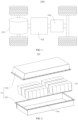
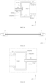
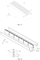
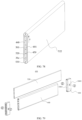
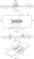
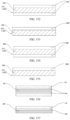
- a box 10 may include a first part 101 and a second part 102 (as shown in Fig. 2 and Fig. 3 ).
- the first part 101 and the second part 102 are covered by each other, and the first part 101 and the second part 102 together define an accommodating space for accommodating a battery cell 20.
- the second part 102 can be of a hollow structure with one end open, the first part 101 is of a plate-like structure, and the first part 101 covers the open side of the second part 102 to form the box having the accommodating space; and both the first part 101 and the second part 102 can also be of a hollow structure with one side open, and the open side of the first part 101 covers the open side of the second part 102 to form the box having the accommodating space.
- the first part 101 and the second part 102 may be in a variety of shapes, such as a cylinder, a cuboid, etc.
- a sealing member such as a sealant, a sealing ring, etc. may also be provided between the first part 101 and the second part 102.
- the battery cell includes an electrode assembly and an electrolyte solution, the electrode assembly being composed of a positive electrode plate, a negative electrode plate and a separator.
- the operation of the battery cell mainly relies on the movement of metal ions between the positive electrode plate and the negative electrode plate.
- the positive electrode plate includes a positive electrode current collector and a positive electrode active material layer.
- the positive electrode active material layer is coated on a surface of the positive electrode current collector, and the current collector not coated with the positive electrode active material layer protrudes from the current collector coated with the positive electrode active material layer and is used as a positive tab.
- the positive electrode current collector may be of a material of aluminum, and the positive electrode active material may be lithium cobalt oxide, lithium iron phosphate, ternary lithium or lithium manganate, etc.
- the negative electrode plate includes a negative electrode current collector and a negative electrode active material layer.
- the negative electrode active material layer is coated on a surface of the negative electrode current collector, and the current collector not coated with the negative electrode active material layer protrudes from the current collector coated with the negative electrode active material layer and is used as a negative tab.
- the material of the negative electrode current collector may be copper, and the negative electrode active material may be carbon or silicon, etc. In order to ensure that no fusing occurs when a large current passes, there are a plurality of positive tabs which are stacked together, and there are a plurality of negative tabs which are stacked together.
- separator there is no particular restriction on the above-mentioned separator. Any well-known separator of a porous structure with electrochemical stability and chemical stability can be used. For example, it can be a single-layer or multi-layer film of one or more of glass fiber, non-woven fabric, polyethylene, polypropylene and polyvinylidene fluoride.
- the material of the separator may be polypropylene (PP) or polyethylene (PE), etc.
- the electrode assembly may have a wound structure or a stacked structure, and the embodiments of the present application are not limited thereto.
- the above-mentioned electrolyte solution includes an organic solvent and an electrolyte salt, wherein the electrolyte salt plays a role in transporting ions between the positive and negative electrodes, and the organic solvent serves as a medium for transporting ions.
- the electrolyte salt may be an electrolyte salt known in the art for the electrolyte of a battery cell, such as one or more of LiPF 6 (lithium hexafluorophosphate), LiBF 4 (lithium tetrafluoroborate), LiClO 4 (lithium perchlorate), LiAsF 6 (lithium hexafluoroarsenate), LiFSI (lithium bis(fluorosulfonyl)imide), LiTFSI (lithium bis(trifluoromethanesulfonyl)imide), LiTFS (lithium trifluoromethanesulfonate), LiDFOB (lithium difluoro(oxalato)borate), LiBOB (lithium bis(oxalato)borate), LiPO 2 F 2 (lithium difluorophosphate), LiDFOP (lithium difluoro bis(oxalato)phosphate), and LiTFOP (lithium tetrafluoro(oxala
- the battery cell may not include an electrolyte solution.
- the battery may include a plurality of battery cells, wherein the plurality of battery cells may be in series connection, parallel connection or parallel-series connection.
- the parallel-series connection refers to a combination of series connection and parallel connection.
- a plurality of battery cells may be in series connection, parallel connection, or parallel-series connection to form a battery module, and then, a plurality of battery modules may be in series connection, parallel connection, or parallel-series connection to form a battery. That is to say, a plurality of battery cells may directly constitute a battery, or may constitute battery modules or battery groups, and the battery modules then constitute a battery.
- the battery is further installed in an electrical apparatus to provide electrical energy to the electrical apparatus.
- At least two battery cells are provided in a battery to be accommodated in an accommodating cavity of a box, and a thermally conductive member is arranged to be connected with the at least two battery cells, and the thermally conductive member is thermally conductively connected with first walls of the at least two battery cells, so that the thermally conductive member is used to conduct the heat from the at least two battery cells.
- a thermally conductive member is arranged to be connected with the at least two battery cells, and the thermally conductive member is thermally conductively connected with first walls of the at least two battery cells, so that the thermally conductive member is used to conduct the heat from the at least two battery cells.
- the heat conduction in the battery can be guaranteed by the above thermally conductive member.
- the technical solution of the embodiments of the present application can effectively guarantee the heat conduction in the battery while improving the energy density of the battery, thus improving the performance of the battery.
- the technical solutions described in the embodiments of the present application are all applicable to various apparatuses using batteries, such as mobile phones, portable devices, laptops, battery vehicles, electric toys, electric tools, electric vehicles, ships, spacecraft, and the like.
- the spacecraft include airplanes, rockets, space shuttles, spaceships, and the like.
- a schematic structural diagram of a vehicle 1000 may be a fuel vehicle, a gas vehicle, or a new-energy vehicle, and the new-energy vehicle may be an all-electric vehicle, a hybrid electric vehicle, an extended range electric vehicle, or the like.
- a motor 101, a controller 102 and a battery 100 may be provided inside the vehicle 1000, and the controller 102 is configured to control the battery 100 to supply power to the motor 101.
- the battery 100 may be arranged at the bottom or the head or the tail of the vehicle 1000. The battery 100 may be used for supplying power to the vehicle 1000.
- the battery 100 may be used as an operating power source of the vehicle 1000, which is used for a circuit system of the vehicle 1000, for example, for operation power requirements of the vehicle 1000 during starting, navigation, and running.
- the battery 100 not only can be used as the operating power source of the vehicle 1000, but also can be used as a driving power source of the vehicle 1000 to provide driving power for the vehicle 1000 by replacing or partially replacing fuel or natural gas.
- the battery 100 may include one or more battery cells 20.
- the battery 100 may include a plurality of battery cells 20.
- the battery 100 may further include a box 10, the interior of the box 10 is a hollow structure, and a plurality of battery cells 20 are accommodated in the box 10.
- the plurality of battery cells 20 are placed in the box 10 after connected in parallel or in series or in a parallel-series combination.
- the battery 100 may further include other structures, which will not be repeated here.
- the battery 100 may further include a bus component (not shown), and the bus component is used for achieving electrical connection between the plurality of battery cells 20, such as parallel connection, series connection, or parallel-series connection.
- the bus component may realize electrical connections between the battery cells 20 by connecting electrode terminals of the battery cells 20.
- the bus component may be fixed to the electrode terminals of the battery cells 20 by welding. Electric energy of the plurality of battery cells 20 may be further led out through an electrically conductive mechanism penetrating the box.
- the electrically conductive mechanism may also belong to the bus component.
- the number of battery cells 20 may be set to any value.
- the plurality of battery cells 20 can be connected in series, in parallel or in parallel-series connection to implement large capacity or power.
- Each battery 100 may include a large quantity of battery cells 20, and therefore, in order to facilitate installation, the battery cells 20 may be arranged in groups, and each group of battery cells 20 forms a battery module.
- the quantity of battery cells 20 included in the battery module is not limited and may be set according to the requirements.
- the battery can include a plurality of battery modules, and these battery modules may be in series, parallel or series-parallel connection.
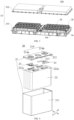
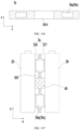
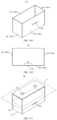
- the battery cell 20 includes one or more electrode assemblies 22, a case 211, and a cover plate 212.
- the case 211 and the cover plate 212 form a shell of the battery cell 20 or a battery casing 21.
- the wall of the case 211 and the cover plate 212 are both called the wall of the battery cell 20.
- the wall of the case 211 includes a bottom wall and four side walls.
- the shape of the case 211 is determined according to the combined shape of one or more electrode assemblies 22.
- the case 211 may be a hollow cuboid, cube, or cylinder, one of the surfaces of the case 211 has an opening to facilitate placing the one or more electrode assemblies 22 in the case 211, and the cover plate 212 covers the opening of the case 211 to isolate the internal environment of the battery cell 20 from the external environment.
- the case 211 is a hollow cuboid or cube
- one plane of the case 211 is an opening surface, i.e., the plane does not have a wall, so that the inside and outside of the case 211 are in communication with each other.
- an end face of the case 211 is an opening surface, i.e., the end face does not have a wall, so that the inside and outside of the case 211 are in communication with each other.
- the cover plate 212 covers the opening and is connected with the case 211 to form an enclosed chamber in which the electrode assemblies 22 are placed.
- the case 211 is filled with electrolyte, such as an electrolyte solution.
- the battery cell 20 may further include two electrode terminals 214, which may be provided on the cover plate 212.
- the cover plate 212 is generally in the shape of a flat plate, and the two electrode terminals 214 are fixed to the flat plate surface of the cover plate 212.
- the two electrode terminals 214 are a positive electrode terminal 214a and a negative electrode terminal 214b respectively.
- Each of the electrode terminals 214 is provided with a corresponding connecting member 23, which may alternatively be referred to as a current collecting member, located between the cover plate 212 and the electrode assembly 22 for electrically connecting the electrode assembly 22 and the electrode terminal 214.
- each electrode assembly 22 has a first tab 221a and a second tab 222a.
- the first tab 221a and the second tab 222a have opposite polarities.
- the first tab 221a is a positive tab
- the second tab 222a is a negative tab.
- the first tab 221a of one or a plurality of electrode assemblies 22 is connected to one electrode terminal via one connecting member 23, and the second tab 222a of the one or a plurality of electrode assemblies 22 is connected to the other electrode terminal via the other connecting member 23.
- the positive electrode terminal 214a is connected to the positive tab via one connecting member 23, and the negative electrode terminal 214b is connected to the negative tab via the other connecting member 23.
- this battery cell 20 there may be a single or a plurality of electrode assemblies 22. As shown in Fig. 4 , there are four separate electrode assemblies 22 in the battery cell 20.
- a pressure relief mechanism 213 may also be provided on the battery cell 20.
- the pressure relief mechanism 213 is configured, when an internal pressure or temperature of the battery cell 20 reaches a threshold, to be actuated to release the internal pressure or heat.
- the pressure relief mechanism 213 can be various possible pressure relief structures, which is not limited in the embodiments of the present application.
- the pressure relief mechanism 213 may be a temperature-sensitive pressure relief mechanism, and the temperature-sensitive pressure relief mechanism is configured to be capable of being melt when the internal temperature of the battery cell 20 provided with the pressure relief mechanism 213 reaches a threshold; and/or the pressure relief mechanism 213 may be a pressure-sensitive pressure relief mechanism, and the pressure-sensitive pressure relief mechanism is configured to be capable of being ruptured when the internal air pressure of the battery cell 20 provided with the pressure relief mechanism 213 reaches a threshold.
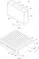
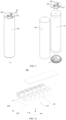
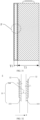
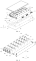
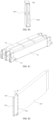
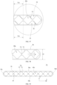
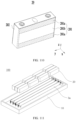
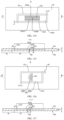
- Fig. 10 shows a schematic structural diagram of a battery cell 100 according to an embodiment of the present application.
- the battery 100 includes a box 10, at least two battery cells 20 and a thermally conductive member 3a.
- the box 10 has an accommodating cavity 10a.
- the at least two battery cells 20 are accommodated in the accommodating cavity 10a.
- Each battery cell 20 includes an electrode assembly 22 and an electrode terminal 214, and the electrode assembly 22 is electrically connected with the electrode terminal 214, so that the battery cell 20 is used for providing electric energy; and
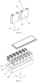
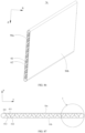
- each battery cell 20 includes a first wall 201, the first wall 201 is the wall with the largest area of the battery cell 20, so that it can be understood that the first wall 201 is the "large surface" of the battery cell.
- the thermally conductive member 3a is connected with the at least two battery cells, and the thermally conductive member 3a is used to accommodate a heat exchange medium.
- the thermally conductive member 3a is disposed opposite to the first walls 201 of the at least two battery cells 20.
- the thermally conductive member 3a is thermally conductively connected with the first walls 201 of the at least two battery cells 20 to utilize the heat exchange medium to adjust the temperature of the at least two battery cells 20.
- the thermally conductive member 3a is provided with a hollow cavity 30a, and the hollow cavity 30a is used to accommodate the heat exchange medium to adjust the temperature of the battery cell 20, and the hollow cavity 30a can reduce the weight of the thermally conductive member 3a while ensuring the strength of the thermally conductive member 3a. It can be applied, for example, to the case where the thickness of the thermally conductive member 3a is relatively large.
- the hollow cavity 30a allows the thermally conductive member 3a to have large compression space in the direction perpendicular to the first wall 201 (for example, the first direction x), thereby providing large expansion space for the battery cell 20.
- the heat exchange medium may be liquid or gas, and the temperature regulation refers to heating or cooling a plurality of battery cells 20.
- the hollow cavity 30a can accommodate the cooling medium to adjust the temperature of a plurality of battery cells 20.
- the heat exchange medium can also be called a cooling medium or a cooling fluid, more specifically, a cooling liquid or a cooling gas.
- the heat exchange medium may also be used for heating, which is not limited in the embodiments of the present application.
- the heat exchange medium may flow in a circulating manner to achieve a better temperature regulation effect.
- the fluid may be water, a mixture of water and ethylene glycol, a thermal conductive oil, a refrigerant or air, etc.
- the cooling medium has a high specific heat capacity to take away more heat. At the same time, the cooling medium has a low boiling point. When the battery cell 20 is under thermal runaway, it can quickly boil and vaporize to absorb heat.
- the thermally conductive member 3a is connected with at least two battery cells 20, and the at least two battery cells 20 can be connected into a whole through the thermally conductive member 3a.
- the large surface of the at least two battery cells 20, that is, the first wall 201, is thermally conductively connected with the thermally conductive member 3a, so that there is heat exchange between the thermally conductive member 3a and the at least two battery cells 20, and the heat exchange area between the thermally conductive member 3a and each battery cell 20 in the at least two battery cells 20 is large, so as to effectively utilize the thermally conductive member 3a to conduct the heat of the battery cell 20, thus improving the heat exchange efficiency between the thermally conductive member 3a and the battery cell 20, which can ensure that the temperature of the battery cell 20 is in a normal state, thus improving the service life and safety performance of the battery cells 20; moreover, when a certain battery cell 20 undergoes thermal runaway, the heat generated by the battery cell 20 under thermal runaway will be taken away by the thermally conductive member 3a which exchanges heat with it, so as to reduce the temperature of the battery cell 20 under thermal runaway and avoid the thermal runaway problem of the adj acent battery cells 20, thus ensuring the safety performance of the battery
- the thermally conductive member 3a can cool the battery cell 20 to lower the temperature of the battery cell 20.
- the thermally conductive member 3a can heat the battery cell 20 to increase the temperature of the battery cell 20.
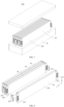
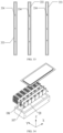
- the battery 100 has a plurality of battery cells 20, and the plurality of battery cells 20 are arranged along a second direction y. That is, the second direction y is the arrangement direction of a plurality of battery cells 20 in a row of battery cells 20 in the battery 100. That is, a row of battery cells 20 in the battery 100 is arranged along the second direction y, and the battery 100 has at least one row of battery cells 20.
- the number of battery cells 20 in a row of battery cells 20 may be 2-20, but this is not limited in the embodiment of the present application; the thermally conductive member 3a extends along the second direction y, and the thermally conductive member 3a is thermally conductively connected with the first wall 201 of each battery cell 20 of the plurality of battery cells 20, so that the first wall 201 of the battery cell 20 can face the thermally conductive member 3a, that is, the first wall 201 of the battery cell 20 can be parallel to the second direction y.
- the first wall 201 directly abuts against the thermally conductive member 3a to achieve heat transfer between the battery cell 20 and the thermally conductive member 3a; or the first wall 201 can indirectly abut against the thermally conductive member 3a, for example, the first wall 201 abuts against the thermally conductive member 3a through a thermally conductive member such as thermally conductive adhesive, which can also realize heat transfer between the battery cell 20 and the thermally conductive member 3a.
- the thermally conductive connection between the thermally conductive member 3a and the first wall 201 means that heat exchange can occur between the first wall 201 and the thermally conductive member 3a, ensuring the thermal management capability of the thermally conductive member 3a for the battery cell 20.
- each battery cell 20 further includes a second wall 202 connected to the first wall 201, the first wall 201 and the second wall 202 intersect, so that the first wall 201 and the second wall 202 are not parallel, and the first wall 201 and the second wall 202 have a common line.
- the electrode terminal 214 is disposed on the second wall 202, so that the electrode terminal 214 is disposed on the wall of the battery cell 20 other than the first wall 201 that intersects with the first wall 201, to facilitate the arrangement of the electrode terminal 214 and to facilitate the avoidance of the electrode terminal 214 and the thermally conductive member 3a, so that the thermally conductive member 3a does not need to be provided with an avoidance portion for avoiding the electrode terminal 214, which is conducive to simplifying the structure of the thermally conductive member 3a.
- each battery cell 20 is roughly formed as a cuboid structure, the length of the battery cell 20 is greater than the width of the battery cell 20 and the height of the battery cell 20, the first wall 201 is located on the side of the battery cell 20 in the first direction x, at least one of the two sides of the battery cell 20 in the second direction y has a second wall 202, and at least one of the two sides of the battery cell 20 in the third direction z has a second wall 202.
- the electrode terminal 214 can be disposed on the second wall 202 of the battery cell 20 in the third direction z; of course, as shown in Fig. 6 , the electrode terminal 214 can also be disposed on the second wall 202 of the battery cell 20 in the second direction y.
- each battery cell 20 may be a blade battery
- the first wall 201 is located at one end of the battery cell 20 in the height direction
- the electrode terminal 214 is provided on the second wall 202, and the electrode terminal 214 may be located at one or both ends of the battery cell 20 in the length direction, and/or the electrode terminal 214 may be located at one or both ends of the battery cell 20 in the width direction.
- the location of the electrode terminal 214 is not limited to this.
- the electrode terminals 214 can also be provided on the first wall 201, which also facilitates the arrangement of the electrode terminals 214; for example, the battery cell 20 is a One-Stop battery cell. It can be seen that the battery 100 in the embodiment of the present application has good flexibility in the location of the electrode terminal.
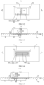
- the electrode terminal 214 is provided on the first wall 201, and the at least two battery cells 20 are arranged in the first direction x.
- each battery cell 20 is provided with a first surface 203 opposite to the first wall 201.
- the first surface 203 is provided with an avoidance groove 203a.
- the avoidance groove 203a of one of two adjacent battery cells 20 is used to accommodate the electrode terminals 214 of the other battery cell 20.
- the first direction x is perpendicular to the first wall 201, so as to achieve a compact arrangement of the plurality of battery cells 20 in the first direction and save space.
- the electrode terminal 214 is provided on the second wall 202, and each battery cell 20 includes two first walls 201 oppositely arranged and two second walls 202 oppositely arranged, at least two electrode terminals 214 are provided, and the plurality of electrode terminals 214 include a positive electrode terminal 214a and a negative electrode terminal 214b.
- At least two electrode terminals 214 are disposed on the same second wall 202 to help save the space occupied by the battery cell 20 on the premise of ensuring that adjacent electrode terminals 214 have appropriate spacing; or, each second wall 202 is provided with at least one electrode terminal 214 such that electrode terminals 214 located on different second walls 202 have sufficient spacing.
- the battery cell 20 includes two first walls 201 oppositely arranged along the first direction x and two second walls 202 oppositely arranged along the third direction z.
- the third direction z is not parallel to the first direction x, for example, the third direction z is perpendicular to the first direction x; and the plurality of electrode terminals 214 are all located on the same second wall 202 of the battery cell 20 in the third direction z.
- the battery cell 20 may also include two second walls 202 oppositely arranged along the second direction y, the second direction y is not parallel to the first direction x, for example, the second direction y is perpendicular to the first direction; and the plurality of electrode terminals 214 are all located on the same second wall 202 of the battery cell 20 in the second direction y.
- the plurality of electrode terminals 214 are located on one side of the battery cell 20 in the second direction y or on one side of the battery cell 20 in the third direction z, when there are multiple battery cells 20 and the multiple battery cells 20 are arranged sequentially along the second direction y, the second walls 202 of two adjacent battery cells 20 face each other in the second direction y.
- first wall 201 may be a flat surface or a curved surface
- second wall 202 may be a flat surface or a curved surface
- the first wall 201 is formed in a cylindrical shape; in this case, the battery cell 20 may be substantially a cylindrical battery cell.
- second walls 202 are provided at both axial ends of the first wall 201, and at least one second wall 202 is provided with the electrode terminal 214, then all electrode terminals 214 of the battery cell 20 are provided on one of the second walls 202, or at least one electrode terminal 214 of the battery cell 20 is provided on one of the second walls 202, and the remaining electrode terminals 214 of the battery cell 20 are provided on the other second wall 202.
- the flexible arrangement of the electrode terminals 214 is facilitated.
- one of the second walls 202 is provided with an exposed electrode terminal 214
- the electrode assembly 22 includes a positive electrode plate 221 and a negative electrode plate 222.
- One of the positive electrode plate 221 and the negative electrode plate 222 is electrically connected to the electrode terminal 214, and the other of the positive electrode plate 221 and the negative electrode plate 222 is electrically connected to the first wall 201, so as to realize normal power supply of the battery cell 20.
- the other one of the positive electrode plate 221 and the negative electrode plate 222 can also be electrically connected to the other second wall 202, that is, the second wall 202 provided with the exposed electrode terminal 214 is not the same wall as the second wall 202 electrically connected with the other one of the positive electrode plate 221 and the negative electrode plate 222, which is also convenient for realizing normal power supply of the battery cell 20.
- At least one battery cell 20 is a pouch battery cell.
- the battery cell 20 is a pouch battery cell; and when the battery 100 includes a plurality of battery cells 20, at least one of the plurality of battery cells 20 is a pouch battery cell. Therefore, it is convenient to enrich the types and structures of the battery 100 and the layout of the battery cells 20, so as to help the battery 100 meet the actual differentiated requirements.
- each battery cell 20 further includes a pressure relief mechanism 213, and the pressure relief mechanism 213 and the electrode terminal 214 are disposed on the same wall of the battery cell 20.
- the pressure relief mechanism 213 and the electrode terminal 214 are both disposed on the second wall 202.
- each battery cell 20 also includes a pressure relief mechanism 213.
- the pressure relief mechanism 213 and the electrode terminal 214 are respectively disposed on two walls of the battery cell 20.
- the location of the pressure relief mechanism 213 relative to the electrode terminal 214 has a certain degree of flexibility.
- the thermally conductive member 3a is fixedly connected to the first wall 201 to realize the connection between the thermally conductive member 3a and the battery cell 20, and to ensure a reliable connection between the battery cell 20 and the thermally conductive member 3a; at the same time, when there are at least two battery cells 20 and the thermally conductive member 3a is connected to the first walls 201 of at least two battery cells 20, the at least two battery cells 20 can be connected as a whole through the thermally conductive member 3a.
- the battery 100 does not need to be provided with side plates or structures such as beams, so that the space utilization inside the battery 100 can be greatly improved, and the energy density of the battery 100 can be improved.
- thermally conductive member 3a can also be fixedly connected to other walls of the battery cell 20, which is not limited to the first wall 201.
- the thermally conductive member 3a is bonded to the first wall 201 of the at least two battery cells 20 through the first adhesive layer, so that the thermally conductive member 3a is bonded to the first wall 201 of the at least two battery cells 20 to achieve a reliable and stable connection between the thermally conductive member 3a and the at least two battery cells 20.
- the first adhesive layer may include a thermally conductive structural adhesive, which not only has good bonding strength and peel strength, but also has thermal conductivity, aging resistance, fatigue resistance, corrosion resistance and other properties, which can improve the connection strength between the battery cell 20 and the thermally conductive member 3a and the thermal management efficiency, making the heat transfer between the battery cell 20 and the thermally conductive member 3a more rapid.
- the first adhesive layer also includes double-sided tape.
- thermally conductive member 3a and the first wall 201 can also be connected through other methods, such as riveting, welding, etc., which is not limited in the present application.
- the bottom of the thermally conductive member 3a is bonded to the bottom wall of the accommodating cavity 10a through a second adhesive layer, so that the bottom of the thermally conductive member 3a is bonded to the bottom wall of the accommodating cavity 10a, so as to realize the fixed connection between the thermally conductive member 3a and the bottom wall of the accommodating cavity 10a.
- the structure is simple and convenient for processing and assembly.
- the thermally conductive member 3a is bonded and fixed with the first wall 201 and the bottom wall of the accommodating cavity 10a, respectively, to ensure the reliable installation of the thermally conductive member 3a.
- the bottom of the battery cell 20 is bonded to the bottom wall of the accommodating cavity 10a through the third adhesive layer to bond the bottom of the battery cell 20 and the bottom wall of the accommodating cavity 10a to achieve a fixed connection between the battery cell 20 and the bottom wall of the accommodating cavity 10a.
- the structure is simple and convenient for processing and assembly; at this time, the thermally conductive member 3a is bonded and fixed to the first wall 201, the battery cell 20 is bonded and fixed to the bottom wall of the accommodating cavity 10a, and the thermally conductive member 3a is indirectly fixedly connected to the bottom wall of the accommodating cavity 10a through the battery cell 20.
- the bottom of the thermally conductive member 3a is bonded to the bottom wall of the accommodating cavity 10a through the second adhesive layer, and the bottom of the battery cell 20 is bonded to the bottom wall of the accommodating cavity 10a through the third adhesive layer.
- At least part of the heat of the battery cell 20 can be transferred to the thermally conductive member 3a through the first adhesive layer, and the thickness of the first adhesive layer is less than or equal to the thickness of the second adhesive layer, so as to reduce the heat transfer resistance between the battery cell 20 and the thermally conductive member 3a and ensure the heat transfer efficiency between the battery cell 20 and the thermally conductive member 3a on the premise of ensuring the reliable connection between the battery cell 20 and the thermally conductive member 3a and the reliable connection between the thermally conductive member 3a and the bottom wall of the accommodating cavity 10a.
- the thickness of the first adhesive layer is less than or equal to the thickness of the third adhesive layer, so as to reduce the heat transfer resistance between the battery cell 20 and the thermally conductive member 3a and ensure the heat transfer efficiency between the battery cell 20 and the thermally conductive member 3a on the premise of ensuring that the battery cell 20 is reliably connected with the thermally conductive member 3a and the bottom wall of the accommodating cavity 10a, respectively.
- the thickness of the first adhesive layer is less than or equal to the thickness of the second adhesive layer, and the thickness of the first adhesive layer is less than or equal to the thickness of the third adhesive layer, then the thickness of the first adhesive layer, the thickness of the second adhesive layer, and the thickness of the third adhesive layer are set reasonably to ensure reasonable distribution and utilization of the adhesive and to achieve reliable placement of the battery cell 20 and the thermally conductive member 3a in the accommodating cavity 10a.
- the thermal conductivity of the first adhesive layer is greater than or equal to the thermal conductivity of the second adhesive layer, and at least part of the heat of the battery cell 20 can be transferred to the thermally conductive member 3a through the first adhesive layer, so as to reduce the heat transfer resistance between the battery cell 20 and the thermally conductive member 3a and ensure the heat transfer efficiency between the battery cell 20 and the thermally conductive member 3a on the premise of ensuring the reliable connection between the battery cell 20 and the thermally conductive member 3a and the reliable connection between the thermally conductive member 3a and the bottom wall of the accommodating cavity 10a.
- the thermal conductivity of the first adhesive layer is greater than or equal to the thermal conductivity of the third adhesive layer, so as to reduce the heat transfer resistance between the battery cell 20 and the thermally conductive member 3a and ensure the heat transfer efficiency between the battery cell 20 and the thermally conductive member 3a on the premise of ensuring that the battery cell 20 is reliably connected with the thermally conductive member 3a and the bottom wall of the accommodating cavity 10a, respectively.
- part of the heat of the battery cell 20 can also be transferred to the bottom wall of the accommodating cavity 10a through the third adhesive layer for dissipation.
- the thermal conductivity of the first adhesive layer is greater than or equal to the thermal conductivity of the second adhesive layer, and the thermal conductivity of the first adhesive layer is greater than or equal to the thermal conductivity of the second adhesive layer, so as to achieve reasonable distribution and utilization of the adhesive, ensure the stable arrangement of the battery cell 20 and the thermally conductive member 3a, and at the same time ensure the rapid dissipation of heat from the battery cell 20.
- the ratio between the thickness of the first adhesive layer and the thermal conductivity of the first adhesive layer is a first ratio
- the ratio between the thickness of the second adhesive layer and the thermal conductivity of the second adhesive layer is a second ratio
- the ratio between the thickness of the third adhesive layer and the thermal conductivity of the third adhesive layer is a third ratio
- the first ratio is less than or equal to the second ratio; and/or, the first ratio is less than or equal to the third ratio. Therefore, on the premise of ensuring the heat exchange effect of the battery cell 20, the adhesive is effectively and rationally utilized to facilitate the reasonable distribution of the adhesive.
- the material of the first adhesive layer and the material of the second adhesive layer are different; or the material of the first adhesive layer and the material of the third adhesive layer are different; or the material of the first adhesive layer, the material of the second adhesive layer, and the material of the third adhesive layer are respectively different.
- the battery 100 includes a plurality of battery modules 100a.
- the battery module 100a includes at least one row of battery groups 20A and at least one thermally conductive member 3a.
- the battery group 20A includes a row of multiple battery cells 20 arranged along the second direction y.
- the first wall 201 of each battery cell 20 of the battery group 20A is fixed and thermally conductively connected to the thermally conductive member 3a.
- the plurality of battery groups 20A and the plurality of thermally conductive members 3a are alternately arranged along the first direction x, and the first direction is perpendicular to the first wall 201.
- the battery module 100a includes N battery groups 20A and N-1 thermally conductive members 3a, wherein the thermally conductive members 3a are disposed between two adjacent battery groups 20A, and N is an integer greater than 1.
- N is an integer greater than 1.
- the plurality of battery modules 100a are arranged along the first direction x, and there are gaps between adjacent battery modules 100a.
- the thermally conductive member 3a can also be provided between the battery group 20A and the inner wall of the box 10.
- a row of battery cells 20 arranged along the second direction y may have only one side in the first direction x connected to the thermally conductive member 3a, or both sides in the first direction x may be connected to the thermally conductive member 3a, which is not limited in the embodiment of the present application.
- the thermally conductive member 3a is used to exchange heat with the battery cell 20 to ensure that the battery cell 20 has a suitable temperature.
- the thermally conductive member 3a may also be called a thermal management component 3b, and the thermal management component 3b is also used to exchange heat with the battery cell 20 so that the battery cell 20 has a suitable temperature.
- the thermally conductive member 3a includes metallic materials and/or non-metallic materials, so that the thermally conductive member 3a has flexible material selection settings, enabling the thermally conductive member 3a to have other good performance in addition to good thermal conductivity, so as to better meet practical differentiated needs.
- the thermally conductive member 3a includes a metal plate 31 and an insulating layer 32, and the insulating layer 32 is disposed on the surface of the metal plate 31.
- the metal plate 31 can ensure the strength of the thermally conductive member 3a
- the insulating layer 32 can make the surface of the thermally conductive member 3a connected to the first wall 201 be an insulating surface, avoiding the electrical connection between the metal plate 31 and the battery cell 20, so as to ensure electrical insulation in the battery 100.
- the insulating layer 32 may be an insulating film bonded to the surface of the metal plate 31 or an insulating paint coated on the surface of the metal plate 31.
- the thermally conductive member 3a is a non-metallic material plate; that is, the thermally conductive member 3a is entirely made of non-metallic insulating material. Of course, in its embodiment, a part of the thermally conductive member 3a is made of non-metallic material.
- the thermally conductive member 3a includes a partition plate 33, the partition plate 33 extends along the second direction y, the partition plate 33 is connected to the first wall 201 of each of the plurality of battery cells 20, and the second direction y is parallel to the first wall 201.
- the first wall 201 with the largest surface area of each battery cell 20 among the plurality of battery cells 20 is connected with the partition plate 33, and the plurality of battery cells 20 are connected into a whole through the partition plate 33, then there is no need to install side plates or structures such as beams in the battery 100, so that the space utilization in the battery 100 can be greatly improved, and the energy density of the battery 100 can be improved.
- the blue film on the surface of the battery cells is easily damaged.
- insulation failure occurs between adjacent battery cells and between the battery cells and the box, and the risk of short circuit of the battery increases.
- a water-cooling plate or heating plate is installed between adjacent battery cells.
- the surface of the water-cooling plate or heating plate has no insulation protection, and the water vapor inside the battery is easily liquefied on the water-cooling plate or heating plate.
- the inventor has conducted in-depth research and set the thermally conductive member 3a to further include an insulating layer 32 for insulating and isolating the first wall 201 of the battery cell 20 and the partition plate 33.
- the insulating layer 32 is arranged on the surface of the partition plate 33 and is not easily damaged by the expansion of the shape of the battery cell or self-heating. In the case that there is no insulating structure on the surface of the battery cell or the blue film on the surface of the battery cell is damaged, when the water vapor inside the battery cell is liquefied on the surface of the partition plate, the insulating layer 32 provided on the surface of the partition plate 33 can play an insulating role between the battery cell 20 and the partition plate 33, which is beneficial to alleviating the problem of short circuit of the battery 100 due to the damage of the blue film of the battery cell 20 or the liquefaction of water vapor on the surface of the partition plate 33, reducing the risk of short circuit of the battery 100, and improving the safety of electrical apparatuses.
- the insulating layer 32 is connected to the surface of the partition plate 33, so that the insulating layer 32 can cover part or all of the surface of the partition plate 33.
- the partition plate 33 is used for heat exchange with the battery cell 20, in which case the partition plate 33 may also be called a thermal management component.
- the thermal management component is a structure that exchanges heat with the battery cell 20, such as a heating resistance wire, a thermally conductive part with heat exchange medium, and some materials that can undergo chemical reactions and temperature changes according to the environmental changes. Heat exchange with the battery cell 20 is achieved through the temperature change of the thermal management component itself.
- the thermal management component can cool down the battery cell 20 to avoid thermal runaway due to excessive temperature of the battery cell 20; if the temperature of the thermal management component is higher than the temperature of the battery cell 20, the thermal management component can heat the battery cell 20 to ensure that the battery 100 can operate normally.
- the thermal management component may also be a structure capable of accommodating a fluid medium, and heat is transferred between the battery cell 20 and the fluid medium through the thermal management component and the insulating layer 32, thereby achieving heat exchange between the battery cell 20 and the fluid medium.
- the fluid medium can be liquid (e.g., water) or gas (e.g., air).
- the thermal management component can cool down the battery cell 20 to avoid thermal runaway due to excessive temperature of the battery cell 20; if the temperature of the fluid medium accommodated inside the thermal management component is higher than the temperature of the battery cell 20, the thermal management component can heat the battery cell 20 to ensure that the battery 100 can operate normally.
- the partition plate 33 can be provided on one side of the battery cell 20 and between the battery cell 20 and the box 10, or between two adjacent battery cells 20.
- the insulating layer 32 may only insulate and isolate the battery cell 20 from the partition plate 33. In some other embodiments, the insulating layer 32 not only can insulate and isolate the battery cell 20 from the partition plate 33, but also can insulate and isolate the partition plate 33 from the inner wall of the box 10, further reducing the risk of short circuit of the battery 100, thereby further improving the safety of the battery 100.
- a plurality of battery cells 20 are stacked and arranged along the first direction x, and a partition plate 33 can be provided between two adjacent battery cells 20.
- Insulating layers 32 are respectively provided on opposite sides of the partition plate 33, so that each battery cell 20 of two adj acent battery cells 20 is insulated and isolated from the partition plate 33 by the insulating layer 32.
- a partition plate 33 may also be provided between the two battery cells 20 located at the ends and the inner wall of the box 10, and the insulating layer 32 connected to the partition plate 33 can only insulate and isolate the battery cell 20 from the partition plate 33; of course, the insulating layer 32 connected to the partition plate 33 can insulate and isolate the battery cell 20 from the partition plate 33, and can also insulate and isolate the partition plate 33 from the inner wall of the box 10, which further reduces the risk of short circuit of the battery 100, thereby further improving the safety of the battery 100.
- the thermal conductivity ⁇ of the insulating layer 32 is greater than or equal to 0. 1W/(m • K), the insulating layer 32 has good thermal conductivity, so that the insulating layer 32 can transfer heat, and there is good thermal conduction performance between the battery cell 20 and the partition plate 33, thereby improving the heat exchange efficiency between the battery cell 20 and the partition plate 33.
- the partition plate 33 is a thermal management component 3b, it is convenient to effectively ensure that the battery cell 20 has a suitable temperature.
- Thermal conductivity refers to the heat transferred through an area of 1 square meter of a 1m thick material in 1 hour under stable heat transfer conditions, with a temperature difference of 1 degree (K, °C) on both sides of the material, and the unit is watt/m ⁇ degree. (W/(m ⁇ K), where K can be replaced by °C).
- the density G of the insulating layer 32 is ⁇ 1.5 g/cm 3 .
- the insulating layer 32 on the surface of the partition plate 33 will increase the weight of the battery 100.
- the density G of the insulating layer 32 is ⁇ 1.5g/ cm3, which makes the weight of the insulating layer 32 small, thereby making the weight of the battery 100 small, and reducing the impact of the arrangement of the insulating layer 32 on the weight of the battery 100, which is beneficial to the lightweight of the battery 100.
- the compressive strength P of the insulating layer 32 satisfies 0.01Mpa ⁇ P ⁇ 200Mpa, which can make the insulating layer 32 have a certain elasticity and can enable the insulating layer 32 to deform by itself when the battery cell 20 expands and deforms, so as to reduce the influence on the whole battery 100, or the elastic insulating layer 32 can also play a cushioning role through its own deformation when the battery 100 is subjected to impact, thereby playing a certain protective role for the battery cell 20 and improving the safety of the battery 100.
- Compressive strength refers to the maximum compressive stress that a sample endures until it breaks or yields during a compression test.
- the material of the insulating layer 32 includes at least one of polyethylene terephthalate, polyimide, and polycarbonate.
- the material of the insulating layer 32 may include only one of polyethylene terephthalate, polyimide, and polycarbonate. In some other embodiments, the material of the insulating layer 32 may include two or three of polyethylene terephthalate, polyimide, and polycarbonate.
- the insulating layer 32 includes a first insulating part and a second insulating parts that are stacked. The first insulating part is made of polyethylene terephthalate, and the second insulating part is made of polyimide; or the first insulating part is made of polyimide, and the second insulating part is made of polycarbonate; or the first insulating part is made of polyethylene terephthalate, and the second insulating part is made of polycarbonate.
- the insulating layer 32 includes a first insulating part, a second insulating part and a third insulating part that are stacked.
- the first insulating part is made of polyethylene terephthalate
- the second insulating part is made of polyimide
- the third insulating part is made of polycarbonate.
- the material of the insulating layer 32 includes at least one of polyethylene terephthalate, polyimide, and polycarbonate.
- the insulating layer 32 has the advantages of good impact strength and good heat aging resistance.
- the thermal conductivity of polyethylene terephthalate is generally 0.24W/m K
- the thermal conductivity of polyimide is generally 0.1-0.5W/m ⁇ K
- the thermal conductivity of polycarbonate is generally 0.16-0.25W. /m K. Therefore, all the three materials have good thermal conductivity. If at least one of the three materials is used to form the insulating layer 32, the insulating layer 32 will have good thermal conductivity, which can improve the heat transfer performance and heat transfer efficiency between the battery cell 20 and the partition plate 33.
- the insulating layer 32 is a coating applied on the surface of the partition plate 33. That is, the insulating layer 32 is connected to the partition plate 33 in a coating manner. In this case, the insulating layer 32 may or may not be connected to the battery cell 20.
- the insulating layer 32 is a coating applied onto the surface of the partition plate 33, which can make the insulating layer 32 adhere to the partition plate 33 more tightly, thereby improving the connection stability between the insulating layer 32 and the partition plate 33 and reducing the risk of the insulating layer 32 falling off from the partition plate 33.
- the insulating layer 32 and the partition plate 33 are connected through an adhesive layer.
- the adhesive layer may be a glue layer disposed on the insulating layer 32 and/or the partition plate 33. After the adhesive layer bonds the partition plate 33 and the insulating layer 32, the adhesive layer is located between the partition plate 33 and the insulating layer 32.
- the insulating layer 32 may or may not be connected to the battery cell 20 through another adhesive layer.
- the insulating layer 32 and the partition plate 33 are connected through an adhesive layer, and the connection method is simple and convenient.
- the insulating layer 32 is potted between the partition plate 33 and the battery cell 20. Potting is a process in which a liquid compound is poured into a device mechanically or manually, and then solidifies into a thermosetting polymer insulation material with excellent performance under normal temperature or heating conditions.
- the insulating layer 32 is provided between the partition plate 33 and the battery cell 20 by potting, which can strengthen the integrity of the overall structure formed by the battery cell 20, the insulating layer 32 and the partition plate 33, and improve the resistance to external impact and vibration.
- the size T1 of the partition plate 33 in the first direction x is less than 0.5 mm, and the first direction x is perpendicular to the first wall 201. This can prevent the partition plate 33 from being too large in the first direction x and occupying too much space inside the battery 100, further improving the space utilization inside the battery 100, thereby increasing the energy density of the battery 100.
- the dimension T1 of the partition plate 33 in the first direction x is not less than 0.05 mm. This can prevent the partition plate 33 from being unable to meet the strength requirements of the battery 100 because the size of the partition plate 33 in the first direction x is too small, that is, the thickness of the partition plate 33 is small and the rigidity of the partition plate 33 is small.
- the insulating layer 32 is provided on the surface of the partition plate 33 to avoid electrical connection between the partition plate 33 and the battery cell 20 and improve the safety of the battery 100.
- the insulating layer 32 may be an insulating film bonded to the surface of the partition plate 33 or an insulating paint coated on the surface of the partition plate 33.
- the size T2 of the insulating layer 32 in the first direction x satisfies: 0.01mm ⁇ T2 ⁇ 0.3mm.
- the insulating layer 32 in the first direction x When the size T2 of the insulating layer 32 in the first direction x is too small, the insulating layer 32 cannot effectively avoid the electrical connection between the battery cell 20 and the partition plate 33, and the battery 100 will have poor insulation, which is a potential safety hazard.
- the size T2 of the insulating layer 22 in the first direction x is too large, it will occupy too much space inside the battery 100, which is not conducive to improving the energy density of the battery 100. Therefore, the value of T2 is set to 0.01 mm to 0.3 mm, which can improve the energy density of the battery 100 and ensure the safety of the battery 100.
- the voltage E of the battery 100 and the size T2 of the insulating layer 32 in the first direction x satisfy: 0.01 ⁇ 10 -3 mm/V ⁇ T2/E ⁇ 3 ⁇ 10 -3 mm/V.
- the insulation effect of the insulating layer 32 is not only related to the thickness of the insulating layer 32, but also related to the thickness of the insulating layer 32 corresponding to unit voltage.
- T2/E is too small, that is, the size T2 of the insulating layer 32 per unit voltage in the first direction x is too small, the insulating layer 32 cannot effectively prevent the electrical connection between the battery cell 20 and the partition plate 33, and the battery 100 will have poor insulation, posing safety risks.
- T2/E is too large, that is, the size T2 of the insulating layer 32 per unit voltage in the first direction x is too large, it will occupy too much space inside the battery 100, which is not conducive to improving the energy density of the battery 100. Therefore, the value of T2/E is set to 0.01 ⁇ 10 -3 ⁇ 3 ⁇ 10 -3 mm/V, which can improve the energy density of the battery 100 and ensure the safety of the battery 100.
- H1 is the size of the partition plate 33 in a third direction z
- L1 is the size of the partition plate 33 in the second direction y
- H2 is the size of a single battery cell 20 in the third direction z
- L2 is the sum of sizes of the plurality of battery cells 20 in the second direction y.
- the contact area between the first walls 201 and the partition plate 33 is too small to meet the strength requirements of the battery 100;
- the area S1 of the surface of the partition plate 33 connected to the first walls 201 is much greater than the total area S2 of the first walls 201 of the plurality of battery cells 20 connected to the same side of the partition plate 33, compared with the battery cells 20, the partition plate 33 occupies too much space inside the battery 100, which is not conducive to improving the energy density of the battery 100. Therefore, the 20 value of S1/S2 is set to 0.25-4 not only can increase the energy density of the battery 100 but also can increase the strength of the battery 100.
- the size H1 of the partition plate 33 and the size H2 of the first wall 201 of the battery cell 20 satisfy: 0.2 ⁇ H1/H2 ⁇ 2, and the third direction z is perpendicular to the first direction x and the second direction y.
- the size H1 of the partition plate 33 is much smaller than the size H2 of the first wall 201 of the battery cell 20, the contact area between the first wall 201 and the partition plate 33 is too small to meet the strength requirements of the battery 100;
- H1/H2 is too large, that is, in the third direction z, the size H1 of the partition plate 33 is much larger than the size H2 of the first wall 201 of the battery cell 20, compared with the battery cells 20, the partition plate 33 occupies too much space inside the battery 100, which is not conducive to improving the energy density of the battery 100. Therefore, the value of H1/H2 is set to 0.2-2, which not only can increase the energy density of the battery 100 but also can improve the strength of the battery 100.
- the size L1 of the partition plate 33 and the size L2 of the plurality of battery cells 20 satisfy: 0.5 ⁇ L1/L2 ⁇ 2.
- the size L1 of the partition plate 33 is much smaller than the size L2 of the first wall 201 of the battery cell 20, the contact area between the first wall 201 and the partition plate 33 is too small to meet the strength requirements of the battery 100;
- H1/H2 is too large, that is, in the second direction y, the size H1 of the partition plate 33 is much larger than the size L2 of the first wall 201 of the battery cell 20, compared with the battery cells 20, the partition plate 33 occupies too much space inside the battery 100, which is not conducive to improving the energy density of the battery 100. Therefore, the value of L1/L2 is set to 0.5-2, which not only can increase the energy density of the battery 100 but also can improve the strength of the battery 100.
- the end of the partition plate 33 in the second direction y is provided with a fixing structure 103, which is connected to a fixing member 104 of the end of the partition plate 33 in the second direction y to fix the partition plate 33.
- T1 is the size of the partition plate in the first direction x
- H1 is the size of the partition plate in the third direction z
- L1 is the size of the partition plate in the second direction y
- H2 is the size of a single battery cell in the third direction z
- L2 is the sum of sizes of the plurality of battery cells in the second direction y
- S1 H1 L1
- S2 H2 L2.
- the size T1 of the partition plate 33 in the first direction x is greater than 5 mm, and the first direction is perpendicular to the first wall 201 to ensure that the partition plate 33 has good reliability in use.
- the battery 10 includes a plurality of battery cells 20 arranged along the second direction Y and a partition plate 33.
- the partition plate 33 extends along the second direction Y and is connected to the first wall 201 of each of the plurality of battery cells 20.
- the size T1 of the partition plate in the first direction x is not greater than 100 mm.
- T1 of the partition plate in the first direction x When the size T1 of the partition plate in the first direction x is too large, it will occupy too much space inside the battery 100, which is not conducive to improving the energy density of the battery 100, so the value of T1 is set to not greater than 100mm, which can effectively improve the energy density of the battery 100.
- the size T1 of the partition plate 33 in the first direction x and the size T3 of the battery cell 20 in the first direction x satisfy: 0.04 ⁇ T1/T3 ⁇ 2.
- T1/T3 When T1/T3 is too small, that is, the size T1 of the partition plate 33 in the first direction x is much smaller than the size T3 of the battery cell 20 in the first direction x, the deformation-absorbing capability of the partition plate 33 is weak and cannot match the expansion and deformation of the battery cell 20, which will reduce the performance of the battery cell 20 in use.
- T1/T3 is too large, that is, the size T1 of the partition plate 33 in the first direction x is much larger than the size T3 of the battery cell 20 in the first direction x, the deformation-absorbing capability of the partition plate 33 is too strong, far exceeding the expansion and deformation space required by the battery cell 20.
- the partition plate 33 occupies too much space inside the battery 10, which is not conducive to improving the energy density of the battery 10. Therefore, the value of T1/T3 is set to 0.04-2, which not only can increase the energy density of the battery 10 but also can absorb the expansion and deformation of the battery cell 20.
- the outer surface of the partition plate 33 is provided with the insulating layer 32, and the size T2 of the insulating layer 32 in the first direction x is 0.01mm-0.3mm.
- the insulating layer 32 By disposing the insulating layer 32 on the outer surface of the partition plate 33, the electrical connection between the battery cell 20 and the partition plate 33 is avoided, and the safety of the battery 10 is improved.
- the size T2 of the insulating layer 31 in the first direction x is too small, the insulating layer 32 cannot effectively prevent the electrical connection between the battery cell 20 and the partition plate 33, and the battery 100 will have poor insulation.
- the size T2 of the insulating layer 32 in the first direction x is too large, it will occupy too much space inside the battery 100, which is not conducive to improving the energy density of the battery 100. Therefore, the value of T2 is set to 0.01mm-0.3mm, which not only can increase the energy density of the battery 100 but also can ensure effective insulation between the battery cell 20 and the partition plate 33.
- the end of the partition plate 33 in the second direction y is provided with a manifold element 106
- the battery 100 is internally provided with a pipe 107
- the pipe 107 is used to transport fluid
- the manifold element 106 is used to collect the fluid.
- the connecting pipe group 42 described below may include the pipe 107.
- T1 is the size of the partition plate in the first direction x
- T3 is the size of the battery cell in the first direction x.
- Table 3 T3(mm) T 1 (mm) T1/T3 Accelerated cycle durability test result 125 5.1 0.041
- the structure is not damaged and there is no diving. 26.5 6 0.226
- the structure is not damaged and there is no diving. 12.5 25 2.000
- the structure is not damaged and there is no diving.
- the structure is not damaged and there is no diving. 44 20 0.455 The structure is not damaged and there is no diving. 44 60 1.364 The structure is not damaged and there is no diving. 70.7 70 0.990 The structure is not damaged and there is no diving. 10 15 1.500 The structure is not damaged and there is no diving. 44 30 0.682 The structure is not damaged and there is no diving. 10.72 6 0.085 The structure is not damaged and there is no diving. 10 6 0.6 The structure is not damaged and there is no diving.
- the thermally conductive member 3a since the thermally conductive member 3a is fixedly connected to the first walls 201 of one or more battery cells 20, in order to ensure the performance of the battery 100, the thermally conductive member 3a must take into account the strength requirements.
- the size of the thermally conductive member 3a in the first direction x is set to 0.1 mm to 100 mm, and the first direction is perpendicular to the first wall 201, so as to balance strength and space requirements.
- the size T4 of the thermally conductive member 3a in the first direction that is, the thickness of the thermally conductive member 3a
- the strength of the thermally conductive member 3a is high; and when T4 is small, the occupied space is little.
- T4 ⁇ 0.1mm the thermally conductive member 3a is easy to be damaged under the action of external force, and when T4>100mm, too much space is occupied, which affects the energy density. Therefore, when the size T4 of the thermally conductive member 3a in the first direction x is 0.1 mm to 100 mm, the space utilization can be improved while ensuring the strength.
- the thermally conductive member 3a is provided in the battery 100 to be thermally conductively connected to the first wall 201 with the largest surface area of the battery cell 20 for conducting heat of the battery cell 20.
- the surface of the thermally conductive member 3a connected to the first wall 201 is an insulating surface to avoid electrical connection between the thermally conductive member 3a and the battery cell 20 and ensure electrical insulation in the battery 100; and the size of the thermally conductive member 3a in the first direction x perpendicular to the first wall 201 is 0.1 mm to 100 mm.
- the thermally conductive member 3a includes a partition plate 33, which is connected to the first wall 201 of each battery cell 20 of the plurality of battery cells 20 arranged along the second direction y, and the second direction is parallel to the first wall 201.
- the middle part of the box 10 of the battery 100 does not need to be provided with structures such as beams, which can greatly improve the space utilization inside the battery 100, thus increasing the energy density of the battery 100; at the same time, the use of the above-mentioned thermally conductive member 3a can also ensure electrical insulation and thermal conduction in the battery 100. Therefore, the technical solution of the embodiment of the present application can improve the energy density of the battery 100 while ensuring the electrical insulation and heat conduction in the battery 100, thereby improving the performance of the battery 100.
- the size T3 of the battery cell 20 in the first direction x and the size T5 of the thermally conductive member 3a in the first direction x satisfy:0 ⁇ T5/T3 ⁇ 7.
- the thermally conductive member 3a occupies much space and affects the energy density.
- the thermally conductive member conducts heat for the battery cells 20 too quickly, safety issues may also arise. For example, thermal runaway of one battery cell 20 may cause thermal runaway of other battery cells 20 connected to the same thermally conductive member.
- the energy density of the battery 100 can be guaranteed, and the safety performance of the battery 100 can be ensured.
- the size T3 of the battery cell 20 in the first direction x and the size T5 of the thermally conductive member 3a in the first direction x can further satisfy 0 ⁇ T5/T3 ⁇ 1 to further increase the energy density of the battery 100 and ensure the safety performance of the battery 100.
- the weight M1 of the battery cell 20 and the weight M2 of the thermally conductive member 3a satisfy: 0 ⁇ M2/M1 ⁇ 20.
- the weight M1 of the battery cell 20 and the weight M2 of the thermally conductive member 3a can further satisfy 0.1 ⁇ M2/M1 ⁇ 1, so as to further improve the energy density of the battery 100 and ensure the safety performance of the battery 100.
- the area S3 of the first wall 201 and the area S4 of the surface of the thermally conductive member 3a connected to the first walls 201 of the plurality of battery cells 20 in one row satisfy 0.2 ⁇ S4/S3 ⁇ 30.
- S2 is the total area of one side surface of the thermally conductive member 3a connected to the battery cells 20.
- S4/S3 is too large, the energy density is affected.
- S4/S3 is too small, the thermal conduction effect is too poor, affecting the safety performance.
- 0.2 ⁇ S4/S3 ⁇ 30 the energy density of the battery 10 can be guaranteed, and the safety performance of the battery 10 can be ensured.
- S4 and S3 can further satisfy 2 ⁇ S4/S3 ⁇ 10 to further enhance the energy density of the battery 100 and ensure the safety performance of the battery 100.
- the specific heat capacity C of the thermally conductive member 3a and the weight M2 of the thermally conductive member 3a satisfy: 0.02KJ/(kg 2 *°C) ⁇ C/M2 ⁇ 100KJ/(kg 2 *°C).
- the thermally conductive member 3a When C/M2 ⁇ 0.02KJ/(kg 2 *°C), the thermally conductive member 3a will absorb much energy, which will cause the temperature of battery cell 20 to be too low, and may cause lithium plating; when C/M2>100KJ/(kg 2 *°C), the heat conduction capability of the thermally conductive member 3a is poor, and the heat will not be taken away in time. When 0.02KJ/(kg 2 *°C) ⁇ C/M2 ⁇ 100KJ/(kg 2 *°C), the safety performance of the battery 100 can be guaranteed.
- C and M2 can further satisfy the following relationship: 0.3KJ/(kg 2 *°C) ⁇ C/M2 ⁇ 20KJ/(kg 2 *°C), to further improve the safety performance of the battery 100.
- the battery 100 may include multiple battery modules 100a.
- the battery module 100a may include at least one row of multiple battery cells 20 arranged along the second direction y and at least one thermally conductive member 3a, and the at least one row of battery cells 20 and the at least one thermally conductive member 3a are alternately arranged in the first direction x. That is, for each battery module 100a, the battery cell rows and the thermally conductive members 3a therein are alternately arranged in the first direction x, and the multiple battery modules 100 are accommodated in the box 10 to form the battery 100.
- the battery module 100a includes two rows of battery cells 20, and one thermally conductive member 3a is disposed in the two rows of battery cells 20. There is no thermally conductive member 3a provided between adjacent battery modules 100a. In this way, it is feasible to dispose few thermally conductive members 3a in the battery 100 in this embodiment, but at the same time, it can be ensured that each battery cell 20 can be connected to the thermally conductive member 3a.
- multiple battery modules 100 are arranged along the first direction x, there is a gap between adjacent battery modules 100, and there is no thermally conductive member 3a between adjacent battery modules 100, then the gap between adjacent battery modules 100a can provide expansion space for the battery cells 20.
- the end of the thermally conductive member 3a in the first direction x is provided with a fixing structure 103, and the thermally conductive member 3a is fixed to the box 10 through the fixing structure 103.
- the fixing structure 103 may include a fixing member 104, the fixing member 104 is fixedly connected to the end of the thermally conductive member 3a and connected to the battery cell 20 located at the end of the thermally conductive member 3a, thereby enhancing the fixing effect of the battery cell 20.
- the battery cells 20 may be bonded and fixed to the box 11.
- adjacent battery cells 20 in each row of battery cells 20 can also be bonded.
- the second walls 2112 of two adjacent battery cells 20 are bonded through structural adhesive.
- the fixing effect of the battery cells 20 can be further enhanced by bonding and fixing the adjacent battery cells 20 in each row of battery cells 20.
- the size H1 of the partition plate 33 and the size H2 of the first wall 201 satisfy: 0.1 ⁇ H1/H2 ⁇ 2, the third direction is perpendicular to the second direction, and the third direction is parallel to the first wall. In this way, the space utilization inside the battery 100 can be further greatly improved, thereby increasing the energy density of the battery 100.
- the size H1 of the partition plate 33 may be the height of the partition plate 33
- the size H2 of the first wall 201 may be the height of the first wall 201.
- the relationship between H1 and H2 satisfies: 0.1 ⁇ H1/H2 ⁇ 2.
- H1/H2 can be 0.1, or 0.4, or 0.6, or 0.9, or 1.2, or 1.5, or 1.8, or 2, etc.
- the partition plate 33 is a thermal management component 3b
- the thermal management component 3b is used to adjust the temperature of the battery cell 20, and the height of the thermal management component 3b in the third direction is H1.
- the thermal management component 3b may be a water-cooling plate, used to cool the battery cells 20 during fast charging or heat the battery cells 20 when the temperature is too low.
- the thermal management component 3b can be made of a material with good thermal conductivity, such as aluminum and other metal materials.
- the size H1 of the partition plate 33 and the size H2 of the first wall 201 also satisfy: 0.3 ⁇ H1/H2 ⁇ 1.3. In this way, it can be ensured that during the fast charging process, the temperature of the battery cell 20 does not exceed 55°C.
- H1/H2 can be 0.3, or 0.5, or 0.8, or 1.0, or 1.1, or 1.3, etc.
- the heat exchange area between the first wall 201 and the partition plate is S
- the relationship between the capacity Q of the battery cell 20 and the heat exchange area S satisfies: 0.03Ah/cm2 ⁇ Q/S ⁇ 6.66Ah/cm2.
- the temperature of the battery cell 20 can be maintained in an appropriate range during the battery charging process, especially the fast charging process; in addition, when the capacity Q of the battery cell is constant, the heat exchange area S can be adjusted to flexibly meet the thermal management requirements of the battery.
- the size H1 of the partition plate 33 is 1.5cm-30cm. In this way, it can be ensured that during the fast charging process of the battery, the temperature of the battery cell 20 does not exceed 55°C.
- a hollow cavity 30a is provided inside the partition plate 33.
- the partition plate 33 provided with the hollow cavity structure has the capability to absorb deformation, which can absorb the expansion and deformation of the battery cell 20 and improve the performance of the battery 100; in other words, the hollow cavity 30a can make the partition plate 33 have large compression space in the first direction x, which can provide large expansion space for the battery cell 20.
- the hollow cavity 30a can reduce the weight of the partition plate 33 while ensuring the strength of the partition plate. For example, it can be applied to the case where the thickness of the partition plate 33 is relatively large.
- the hollow cavity 30a can be used to accommodate a heat exchange medium to adjust the temperature of the battery cell 20, so that the temperature of the battery cell 20 can be easily adjusted to a suitable range at any time, thereby improving the stability and safety of the battery cell 20. It can be seen that at this time, the hollow cavity 30a can also be called a heat exchange cavity, and the hollow cavity 30a corresponds to one or more flow channels 30c for accommodating the heat exchange medium.
- the fluid mentioned here can be a liquid that can adjust the temperature and does not chemically react with the material of the hollow cavity 30a, such as water, which is not limited in the present application.
- the size of the hollow cavity 30a is W, and the capacity Q of the battery cell 20 and the size W of the hollow cavity 30a satisfy: 1.0 Ah/mm ⁇ Q/W ⁇ 400Ah/mm, and the first direction x is perpendicular to the first wall 201, so as to effectively utilize the partition plate 33 to prevent heat diffusion between the battery cells 20.
- the partition plate 33 to prevent heat diffusion between the battery cells 20.
- the size W of the hollow cavity 30a is small, the volume of the fluid that can be accommodated in or flow through the hollow cavity 30a is small, and the battery cell 20 cannot be cooled in time.
- the temperature of a certain battery cell 20 is too high, if the battery cell 20 is not cooled in time, the heat of the battery cell 20 would diffuse to the adjacent battery cells 20, causing the temperature of the adjacent battery cells to 20 to be too high, then abnormality occurs, which affects the performance of the entire battery 10.
- the size W of the hollow cavity 30a is large, the volume of the fluid that can be accommodated in or flow through the hollow cavity 104 is large, and the battery cell 20 can be fully cooled.
- the large size of the hollow cavity 30a results in large space occupied by the partition plate 33, which cannot ensure the energy density of the battery 100.
- the partition plate 33 with excessively large volume also leads to an increase in cost.
- the hollow cavity 30a may be formed by a pair of thermally conductive plates 333 in the partition plate 33, and the size W of the hollow cavity 30a along the first direction x may be the distance between the inner walls of the two thermally conductive plates 333 along the first direction x.
- the partition plate 33 is a water-cooling plate
- the larger the size W of the hollow cavity 30a the faster the heat of the battery cell 20 will dissipate, so the battery cell 20 will be cooled faster, which can prevent the heat of battery cell 20 from diffusing to adjacent battery cells 20.
- the fluid may flow in a circulating manner to achieve a better temperature regulation effect.
- the fluid may be water, a mixture of water and ethanol, a refrigerant or air, etc.
- Fig. 36 is a schematic structural diagram of connection between a battery cell and a thermal management component according to an embodiment of the present application.
- Fig. 37 is a cross-sectional view taken along the A-A direction in Fig. 36
- Fig. 38 is an enlarged schematic view of the G area in Fig. 37 .
- the size T3 of the battery cell 20 along the first direction x and the size H of the thermal management component 3b along the third direction satisfy: 0.03 ⁇ T3/H ⁇ 5.5, and the three direction is perpendicular to the first direction and the second direction.
- the size T3 of the battery cell 20 along the first direction x may be the thickness T3 of the battery cell 20.
- the thickness T3 of the battery cell 20 is related to the capacity Q of the battery cell 20, and the greater the thickness T3, the greater the capacity Q.
- the size H1 of the partition plate 33 along the third direction may be the height H of the thermal management component 3b along the third direction.
- the larger H is, the larger the volume of the thermal management component 3b will be, the larger the occupied space will be, and the stronger the thermal management capability will be.
- the thermal management component 3 b is a water-cooling plate
- the larger H is, the stronger the cooling capacity for the battery cells 20 is, and the more effectively it can prevent the heat of the battery cells 20 from diffusing to adjacent battery cells 20.
- the size H of the thermal management component 3b along the third direction is large, which can fully meet the requirement of preventing the diffusion of heat of the battery cell 20, but it is difficult to meet the energy density requirements of the battery 10.
- the thermal management component 3b with a large volume will also lead to a decrease in production cost.
- the thermal management component 3b is unable to meet the thermal management requirements of the battery cell 20, that is, the heat of the battery cell 20 cannot be transmitted out in time, thereby causing the heat to diffuse to the adjacent battery cells 20, causing abnormality in the temperature of other battery cells 20, and further affecting the performance of the battery 10.
- the size H1 of the partition plate 33 along the third direction is 15mm-300mm. In this way, the partition plate 33 can balance the requirements of strength and thermal management performance.
- the size W of the hollow cavity 30a is 0.8mm-50mm. In this way, the requirements of strength and thermal management performance can be balanced.
- the partition plate 33 further includes a pair of thermally conductive plates 333 disposed oppositely along the first direction, the hollow cavity 30a is disposed between the pair of thermally conductive plates 333, and the first direction is perpendicular to the first wall 201.
- each thermally conductive plate 333 extends along the second direction, and the two thermally conductive plates 333 face each other along the first direction to form the hollow cavity 30a between the two thermally conductive plates 333.
- the hollow cavity 30a can serve as a flow channel of a heat exchange medium, so that the partition plate 33 is formed as a thermally conductive member 3a or a thermal management member 3b.
- the size D of the thermally conductive plate 333 in the first direction x is 0.1 mm-5 mm.
- the hollow cavity 30a occupies most of the space of the partition plate 33 under the condition that the space inside the partition plate 33 is fixed. In this case, the rigidity of the partition plate 33 is poor and cannot effectively improve the structural strength of the battery 10.
- the size D of the thermally conductive plate 333 in the first direction is too large, the hollow cavity 30a inside the partition plate 33 is very small and can accommodate very little fluid, and the temperature of the battery cell 20 cannot be effectively adjusted. Therefore, the value of D is set to 0.1mm-5mm.
- the sizes D of the pair of thermally conductive plates 333 of the partition plate 333 in the first direction may be the same or different.
- the two thermally conductive plates 333 can be made of a material with good thermal conductivity, such as aluminum and other metal materials.
- the partition plate 33 further includes reinforcing ribs 334, which are disposed between the pair of thermally conductive plates 33 to enhance the structural strength of the partition plate 33.
- one reinforcing rib 334 there is one reinforcing rib 334, so that one or more hollow cavities 30a can be formed between the pair of thermally conductive plates 333.
- different hollow cavities 30a may be independent of each other or may be communicated through adapters.
- the reinforcing ribs 334 are connected to only one of the pair of thermally conductive plates 333, the reinforcing ribs 334 are cantilevers with one end connected to the thermally conductive plate 333, and at this time, the hollow cavity 30a can correspond to a flow channel 30c.
- the reinforcing ribs 334 are respectively connected the pair of thermally conductive plates 333, the hollow cavity 30a can correspond to a plurality of flow channels 30c.
- the number of the reinforcing ribs 334 can be specifically set according to requirements, which is not limited in the embodiments of the present application.
- the reinforcing ribs 334 are connected to at least one of the pair of thermally conductive plates 333 to further ensure the structural strength of the partition plate 333.
- the reinforcing ribs 334 may be provided on only one thermally conductive plate 333, or the reinforcing ribs 334 may be located between the pair of thermally conductive plates 333 and connected to the pair of thermally conductive plates 333.
- the included angle between the reinforcing ribs 334 and the thermally conductive plates 333 may be an acute angle to provide more expansion space for the battery cell 20.
- the included angle between the reinforcing ribs 334 and the thermally conductive plate 333 may also be a right angle, so that the partition plate can withstand a relatively great pressure.
- the reinforcing ribs 334 can be of a special shape, such as C-shaped, wavy-shaped, or cross-shaped, which can effectively absorb expansion, increase turbulence, and enhance the heat transfer effect.
- the reinforcing rib 334 includes a first reinforcing rib 3341. Both ends of the first reinforcing rib 3341 are respectively connected to the pair of thermally conductive plates 333.
- the first reinforcing rib 3341 is used to support the pair of thermally conductive plates 333.
- the partition plate 333 deforms to absorb the expansion force of the battery cell 20
- the first reinforcing rib 3341 can deform to adapt to the pair of thermally conductive plates 33 that can at least partially move in the direction close to each other along the first direction x.
- the first reinforcing rib 3341 is arranged inclinedly with respect to the first direction x, then the included angle between the first reinforcing rib 3341 and one of the pair of thermally conductive plates 333 is less than 90°, which can improve the bending property of the first reinforcing rib 3341, so the first reinforcing rib can be better deformed to meet the requirements of the partition plate 33 to absorb expansion force, and avoid the risk of small deformation space and easy fracture and failure caused by a straight shape.
- first reinforcing ribs 3341 there may be one or more first reinforcing ribs 3341, and the plurality of first reinforcing ribs 3341 may be spaced apart along the third direction z, wherein the spacing size between two adjacent first reinforcing ribs 3341 may be the same or different.
- the material of the first reinforcing rib 3341 can be made of a reinforcing rib structure, which ensures the support function while achieving a lightweight design of the partition plate 333, thereby achieving an overall lightweight design of the battery 100.
- the first reinforcing rib 3341 is connected to the pair of thermally conductive plates 333, and the first reinforcing rib 3341 extends along the second direction y to increase the connection area between the first reinforcing rib 3341 and each thermally conductive plate 333 and improve the support strength.
- the first reinforcing rib 3341 is in the form of a plate-like structure, so that it can be better deformed to meet the requirements of the partition plate for absorbing the expansion force of the battery cell 20; in addition, it is beneficial to production and processing and improvement of manufacturing efficiency.
- the range of the included angle between the first reinforcing rib 3341 and the first direction is 30°-60°, then the range of the included angle between the first reinforcing rib 3341 and one of the pair of thermally conductive plates 333 is 30°-60°, which is conducive to better deformation while meeting support needs, and fracture is not easy to occur.
- the inclination directions of two adjacent first reinforcing ribs 3341 may be the same or different.
- the reinforcing rib 334 also includes a second reinforcing rib 3342.
- One end of the second reinforcing rib 3341 is connected to one of the pair of thermally conductive plates 333, and the other end of the second reinforcing rib 3342 is spaced apart from the other one of the pair of thermally conductive plates 333.
- the extension size of the second reinforcing rib 3342 in the first direction x is smaller than the distance between the pair of thermally conductive plates 333.
- the second reinforcing rib 3342 by providing the above-mentioned second reinforcing rib 3342, a better support effect can be achieved by cooperating with the first reinforcing rib 3341, and the deformation range of the partition plate 33 can be controlled.
- the deformation of the partition plate 33 can be further limited, thus avoid blockage of the flow channel 30c corresponding to the hollow cavity 30a, and ensuring the effectiveness of the flow channel 30c, thereby ensuring the effectiveness of the partition plate 33.
- the pair of thermally conductive plates 333 are respectively a first thermally conductive plate 3331 and a second thermally conductive plate 3332.
- the second reinforcing rib 3342 can be provided on the first thermally conductive plate 3331 or be provided on the second thermally conductive plate 3332.
- both the first thermally conductive plate 3331 and the second thermally conductive plate 3332 are provided with second reinforcing ribs 3342.
- a second reinforcing rib 3342 is provided between two adjacent first reinforcing ribs 3341.
- one of two adjacent second reinforcing ribs 3342 is provided on the first thermally conductive plate 3331 and the other is provided on the second thermally conductive plate 3332 to ensure that the first thermally conductive plate 3331 and the second thermally conductive plate 3332 are evenly stressed and do not bear too much weight.
- the second reinforcing rib 3342 extends along the first direction x and protrudes from one of the pair of thermally conductive plates 333, which simplifies the structure of the second reinforcing rib 3342 and facilitates processing.
- the second reinforcing rib 3342 is in the form of a polygonal column, so that the second reinforcing rib 3342 has a sufficient cross-sectional area.
- the partition plate 33 absorbs the expansion force of the battery cell 20 and deforms such that the second reinforcing rib 3342 provided on one of the pair of thermally conductive plates 333 contacts with the other, the second reinforcing rib 3342 can have a sufficient contact area to better improve the supporting capacity and avoid damage or even failure of the second reinforcing rib 3342 which may cause contact between the two thermally conductive plates 333, thereby ensuring the effectiveness of the partition plate 33.
- the first reinforcing rib 3341 and the second reinforcing rib 3342 are spaced apart to ensure that the two thermally conductive plates 333 are relatively evenly stressed.
- the first reinforcing rib 3341 and the second reinforcing rib 3342 are alternately distributed along the third direction z (for example, the height direction of the box 10).
- the first reinforcing rib 3341 and the second reinforcing rib 3342 are alternately distributed along the third direction z (for example, the height direction of the box 10).
- two adjacent first reinforcing rib 3341 and second reinforcing rib 3342 can be arranged alternately on the first thermally conductive plate 3331 and the second thermally conductive plate 3332.
- the position of the second reinforcing ribs 3342 can also be set according to a certain arrangement rule.
- one of two adjacent second reinforcing ribs 3342 is provided on the first thermally conductive plate 3331 and the other is provided on the second thermally conductive plate 3332 to ensure that the first thermally conductive plate 3331 and the second thermally conductive plate 3332 are evenly stressed and do not bear too much weight.
- the thickness D of the thermally conductive plate 333 and the size W of the hollow cavity satisfy: 0.01 ⁇ D/W ⁇ 25, so as to balance strength and thermal management performance requirements.
- the size W of the hollow cavity 30a when the size W of the hollow cavity 30a is large, the flow resistance of the fluid in the hollow cavity 30a is low, which can increase the heat exchange amount of the partition plate 33 per unit time; when the thickness D of the thermally conductive plate 333 is large, the strength of the partition plate 33 is high.
- D/W is less than 0.01, the size W of the hollow cavity 30a is large enough, but the space occupied is too large; or under the given space of the partition plate 33, the thickness D of the thermally conductive plate 333 may be too small, resulting in insufficient strength.
- the vibration and impact requirements of the battery 20 cannot be met, and even the partition plate 33 may be collapsed when it is initially assembled.
- the thickness D of the thermally conductive plate 333 is large enough, but under the given space of the partition plate 33, the size W of the hollow cavity 30a may be too small, the flow resistance of the fluid in the hollow cavity 30a increases, and the heat transfer performance becomes worse or the hollow cavity 30a is blocked during use; at the same time, because the wall thickness of the thermally conductive plate 333 is too large, the force generated by the expansion of the battery cell 20 cannot meet the collapse force on the partition plate 33 corresponding to the expansion space required by the battery cell 20, that is, the partition plate 33 will not be able to provide the expansion space required by the battery cell 20 in time, which will accelerate the decrease of the capacity of the battery cell 20. Therefore, when the thickness D of the thermally conductive plate 333 and the size W of the hollow cavity 30a satisfy 0.01 ⁇ D/W ⁇ 25, the strength and thermal management performance requirements can be balanced to ensure the performance of the battery 100.
- the fluid when 0.01 ⁇ D/W ⁇ 0.1, can be solid-liquid phase change material or liquid working medium.
- the outer layer of the partition plate 33 can be made of a film-like material as a covering, and the inside can be filled with a skeleton structure for reinforcement. This solution can be used in situations where the strength requirements are low or the compressibility requirements for the partition plate 33 is high.
- fluid working medium convection and heat exchange or vapor-liquid phase change cooling scheme can be adopted inside the partition plate 33, and the liquid working medium is used as the heat exchange medium to ensure the heat exchange performance of the partition plate 33.
- the partition plate 33 can adopt a vapor-liquid phase change cooling scheme, in which the overall pressure is increased by adjusting the internal gap to ensure that the working medium exists in liquid form inside the partition plate 33, so as to prevent the coexistence of vapor and liquid phases caused by pressure loss, thereby providing heat exchange performance; at the same time, the thickness D of the thermally conductive plate 333 is large enough to prevent the partition plate 33 from rupturing due to an increase in pressure caused by the vaporization of internal working medium during heating.
- the thickness D of the thermally conductive plate 333 and the size W of the hollow cavity 30a further satisfy 0.05 ⁇ D/W ⁇ 15, and further satisfy 0.1 ⁇ D/W ⁇ 1, so as to better balance space, strength and thermal management, thereby further improving the performance of battery 100.
- the size T1 of the partition plate 33 in the first direction x is 0.3 mm-100 mm.
- the thickness D of the thermally conductive plate 333 is 0.1mm-25mm.
- the thickness D of the thermally conductive plate 333 is too large, too much space will be occupied, and the partition plate 33 will not be able to provide the expansion space required by the battery cells 20 in time. If D is too small, the strength will be too low. Therefore, when the thickness D of the thermally conductive plate 333 is 0.1 mm-25 mm, the space, strength, and expansion requirements of the battery cell 20 can be balanced to ensure the performance of the battery 100.
- the size W of the hollow cavity 30a in the first direction is 0.1mm-50mm.
- the size W of the hollow cavity 30a needs to be at least larger than the particle size of possible impurities inside to avoid blockage during application. Moreover, if the size W of the hollow cavity 30a is too small, the flow resistance of the fluid in the hollow cavity 30a will increase, and the heat exchange performance will become worse, so the size W of the hollow cavity 30a is not less than 0.1 mm. If the size W of the hollow cavity 30a is too large, too much space will be occupied, or the strength will be insufficient. Therefore, when the size W of the hollow cavity 30a is 0.1mm-50mm, the space, strength and thermal management performance can be balanced to ensure the performance of the battery 100.
- the size T1 of the partition plate 33 in the first direction x and the area S3 of the first wall 201 satisfy: 0.03mm -1 ⁇ T1/S3*1000 ⁇ 2mm -1 .
- the heat exchange performance requirements and size and space requirements of the battery cell 20 can be meet. Specifically, when the area S3 of the first wall 201 of the battery cell 20 is large, the cooling area is large, which can reduce the resistance of heat transfer from the partition plate 33 to the surface of the battery cell 20; when the total thickness T1 of the partition plate 33 is large, the strength can be increased. If T1/S3*1000 is less than 0.03mm -1 , the area S3 of the first wall 201 of the battery cell 20 is large enough, but the partition plate 33 is too thin, resulting in insufficient strength, and the partition plate 33 may be damaged or cracked during use.
- T1/S3*1000 is greater than 2
- the partition plate 33 is thick enough, but the area S3 of the first wall 201 of the battery cell 20 is too small, and the cooling surface that the partition plate 33 can provide to the battery cell 20 is insufficient, so there is a risk that the heat dissipation requirements of the battery cell 20 cannot be met. Therefore, when the total thickness T1 of the partition plate 33 and the area S3 of the first wall 201 satisfy 0.03mm -1 ⁇ T1/S3*1000 ⁇ 2mm -1 , the strength and thermal management performance requirements 20 can be balanced to ensure the performance of the battery 100.
- the partition plate 33 also includes a reinforcing rib 334.
- the reinforcing rib 334 is provided between the pair of thermally conductive plates 333.
- the thickness X of the reinforcing rib 334 is not less than (-0.0005*F+0.4738) mm, where F is the tensile strength of the material of the reinforcing rib 334 in Mpa. That is, the minimum thickness X of the reinforcing rib 334 can be (-0.0005*F+0.4738) mm.
- the thickness X of the reinforcing rib 334 is related to the tensile strength of its material. According to the above relational expression, in order to meet the stress requirements of the partition plate 33, the higher the strength of the material is, the smaller the thickness X of the internal reinforcing rib 334 can be, thus saving space and improving energy density.
- the thickness X of the reinforcing rib 334 may be 0.2 mm-1 mm.
- the battery cell 20 and the partition plate 33 shown in Fig. 45 were used to carry out simulation tests on the heating rate and the deformation force of the thermal management component.
- the test results are shown in Table 10.
- L is the size of the battery cell 20 in the second direction y
- T3 is the size of the battery cell 20 in the first direction x
- H2 is the size of the first wall 201 of the battery cell 20 in the third direction z
- the third direction is perpendicular to the first direction x and the second direction y.
- the partition plate 33 is provided with a medium inlet 3412 and a medium outlet 3422, and the hollow cavity 30a is communicated with the medium inlet 3412 and the medium outlet 3422, so that the hollow cavity 30a can accommodate the heat exchange medium to adjust the temperature of the battery cell 20;
- the interior of the partition plate 33 is provided with a chamber 30b that is disconnected from both the medium inlet 3412 and the medium outlet 3422, so that the chamber 30b can prevent the heat exchange medium from entering, so as to adjust the temperature of the battery cell 20 while reducing the weight of the partition plate 33, thereby realizing the lightweight of the partition plate 33, and the phenomenon that the weight of the partition plate 33 is increased due to the heat exchange medium entering the chamber 30b can be alleviated during use, thereby effectively reducing the weight of the battery 100 having such partition plate 33, which is beneficial to increasing the energy density of the battery 100 and improving the performance of the battery 100 during use.
- the medium inlet 3412 and the medium outlet 3422 are respectively provided at both ends of the partition plate 33, and the hollow cavity 30a and the chamber 30b are both provided inside the partition plate 33.
- the hollow cavity 30a is communicated with the medium inlet 3412 and the medium outlet 3422, that is, both ends of the hollow cavity 30a are connected to the medium inlet 3412 and the medium outlet 3422 respectively, so that the fluid medium can flow into or out of the hollow cavity 30a.
- the chamber 30b is disconnected from both the medium inlet 3412 and the medium outlet 3422, that is, the chamber 30b is not in communication with both the medium inlet 3412 and the medium outlet 3422, so that the fluid medium cannot enter the chamber 30b.
- the number of chambers 30b disposed inside the partition plate 33 may be one or multiple, and similarly, the number of hollow cavities 30a disposed inside the partition plate 33 may be one or multiple; when there are multiple hollow cavities 30a, each hollow cavity 30a is communicated with the medium inlet 3412 and the medium outlet 3422, that is, both ends of the plurality of hollow cavities 30a are connected to the medium inlet 3412 and the medium outlet 3422 respectively.
- the partition plate 33 includes a plate main body 331 (or referred to as body part), a first confluence member 341 and a second confluence member 342.
- the plate main body 331 is provided with the hollow cavity 30a and the chamber 30b.
- the first confluence member 341 and the second confluence member 342 are respectively provided at both ends of the plate main body 331, and the medium inlet 3412 and the medium outlet 3422 are respectively provided at the first confluence member 341 and the second confluence member 342.
- the hollow cavity 30a and the chamber 30b are both disposed inside the plate main body 331.
- the hollow cavity 30a and the chamber 30b both extend along the length direction of the plate main body 331, and the two ends of the hollow cavity 30a run through the two ends of the plate main body 331 respectively, so that the hollow cavity 30a can be communicated with the medium inlet 3412 of the first confluence member 341 and the medium outlet 3422 of the second confluence member 342.
- the plate main body 331, the first confluence member 341 and the second confluence member 342 can be of an integrated structure or be separate structures.
- the plate main body 331, the first confluence member 341 and the second confluence member 342 are of an integrated structure, the plate main body 331, the first confluence member 341 and the second confluence member 342 can be made by casting or injection molding.
- the plate main body 3315, the first confluence member 341 and the second confluence member 342 are separate structures, the first confluence member 341 and the second confluence member 342 can be connected to both ends of the plate main body 331 by bolting, snap-fit or bonding.
- a channel 3151 is provided inside the plate main body 331, and the channel 3151 runs through both ends of the plate main body 331 in the length direction of the plate main body 331.
- the partition plate 33 also includes a blocking member 318, which is connected to the plate main body 331. The blocking member 318 blocks both ends of the channel 3151 to form the chamber 30b.
- both ends of the channel 3151 running through the plate main body 331 are provided with blocking members 318. After the two ends of the channel 3151 are blocked by the blocking members 318, the sealed chamber 30b can be formed. Thus, the chamber 30b is disconnected from both the medium inlet 3412 and the medium outlet 3422.
- the blocking member 318 can be a metal sheet, a rubber plug, a silicone plug, etc.
- different blocking members 318 can be used according to the size of the channel 3151.
- the blocking member can be connected to one end of the plate main body 331 by metal sheet welding to block the channel 3151, and a rubber plug or silicone plug can also be used to block the channel 3151.
- a rubber plug or silicone plug can be used to stick in the channel 3151 to block the channel 3151.
- the blocking member 318 is detachably connected to the plate main body 331.
- the blocking member 318 is detachably connected to the plate main body 331, so that the blocking member 318 can be quickly disassembled and replaced.
- it is convenient to block different channels 3151 according to actual needs during use to meet different needs.
- the blocking member 318 can be repaired and replaced, which is beneficial to extending the service life of the partition plate 33.
- the blocking member 318 is snap-fitted to one end of the channel 3151 to block the channel 3151.
- the blocking member 318 can also be detachably connected to the plate main body 331 by bolting or lock-joint.
- the chamber 30b is a closed structure formed by blocking the channel 3151 inside the plate main body 331 with the blocking member 318.
- the chamber 30b can also be a structure formed integrally with the plate main body 331. That is, the chamber 30b is a structure with a hollow cavity inside the plate main body 331 formed by casting or stamping processes, that is, the blocking member 318 and the plate main body 331 are of an integrated structure.
- the channel 3151 is formed inside the plate main body 331 and runs through both ends of the plate main body 331 in the length direction of the plate main body 331.
- the blocking member 318 can block both ends of the channel 3151, thereby forming the chamber 30b that is disconnected from both the medium inlet 3412 and the medium outlet 3422.
- the structure is simple and easy to manufacture and process, and different channels 3151 can be blocked according to actual needs to expand the applicable scope of the partition plate 33.
- a first chamber communicated with the medium inlet 3412 is formed inside the first confluence member 341
- a second chamber communicated with the medium outlet 3422 is formed inside the second confluence member 342
- the flow channel 30c runs through the two ends of the plate main body 331 in the length direction of the plate main body 331 to be in communication with the first chamber and the second chamber.
- the first chamber communicated with the medium inlet 3412 is formed inside the first confluence member 341, that is, the first chamber is formed inside the first confluence member 341, and the medium inlet 3412 runs through the wall of the first chamber, such that when the first confluence member 341 is installed at one end of the plate main body 331, the flow channel 30c running through one end of the plate main body 331 can be communicated with the first chamber inside the first confluence member 341, so that the plurality of flow channels 30c are communicated with the first chamber of the first confluence member 341 to realize the communication between the plurality of flow channels 30c and the medium inlet 3412.
- the second chamber communicated with the medium outlet 3422 is formed inside the second confluence member 342, that is, the second chamber is formed inside the second confluence member 342, and the medium outlet 3422 runs through the wall of the second chamber, such that when the second confluence member 342 is installed at one end of the plate main body 331, the flow channel 30c running through one end of the plate main body 331 can be communicated with the second chamber inside the second confluence member 342, so that the plurality of flow channels 30c are communicated with the second chamber of the second confluence member 342 to realize the communication between the plurality of flow channels 30c and the medium outlet 3422.
- the chamber 30b is not communicated with the first cavity of the first confluence member 341 and the second cavity of the second confluence member 342, so that the chamber 30b is disconnected from both the medium inlet 3412 and the medium outlet 3422.
- the first confluence member 341 is provided with the first chamber communicated with the flow channel 30c
- the second confluence member 342 is provided with the second chamber communicated with the medium outlet 3422, so the flow channel 30c can run through both ends of the plate main body 331 and be communicated with both the first chamber and the second chamber, such that the flow channel 30c is communicated with both the medium inlet 3412 and the medium outlet 3422.
- the fluid medium can be simultaneously introduced into the plurality of flow channels 30c through the medium inlet 3412 and the medium outlet 3422 during use, so as to improve the use efficiency.
- both the chamber 30b and the hollow cavity 30a extend along the length direction of the plate main body 331 and are arranged along the width direction of the plate main body 331 (i.e., the third direction z).
- the partition plate 33 is provided with a hollow cavity 30a and a plurality of chambers 30b.
- the hollow cavity 30a corresponds to a plurality of flow channels 30c.
- the chamber 30b and the flow channels 30c all extend along the length direction of the plate main body 331, and the plurality of chambers 30b and the plurality of flow channels 30c are all arranged along the width direction of the plate main body 331.
- the plurality of chambers 30b and the plurality of flow channels 30c can be arranged in various ways.
- the chambers 30b and the flow channels 30c can be arranged alternately, or multiple chambers 30b can be located on one side of the plurality of flow channels 30c along the width direction of the plate main body 331, or along the width direction of the plate main body 331, a plurality of chambers 30b are provided at the middle position of the plate main body 331, and flow channels 30c are provided on both sides of the plurality of chambers 30b.
- a plurality of chambers 30b are provided at the middle position of the plate main body 331
- flow channels 30c are provided on both sides of the plurality of chambers 30b.
- two flow channels 30c are provided at the middle position of the plate main body 331
- two sides of the two flow channels 30c are respectively provided with three chambers 30b
- both ends of the plate main body 331 are respectively provided with one flow channel 30c.
- the chambers 30b and the flow channels 30c all extend along the length direction of the plate main body 331 and are arranged along the width direction of the plate main body 331, making it easier to process and manufacture the chambers 30b and the flow channels 30c, and facilitating the optimization of arrangement of the flow channels 30c, which is beneficial to improving the temperature adjusting capability of the partition plate 33 to the battery 100.
- a flow channel 30c is provided at the middle position of the plate main body 331 along the width direction of the plate main body 331.
- the flow channel 30c is provided at the middle position of the plate main body 331. If there is one flow channel 30c, the flow channel 30c is disposed at the middle position of the plate main body 331. If there are multiple flow channels 30c, then at least part of the multiple flow channels 30c are located at the middle position of the plate main body 331 in the width direction of the plate main body 331. For example, in Figs. 48 and 49 , two flow channels 30c are provided at the middle position of the plate main body 331 along the width direction of the plate main body 1. Of course, in other embodiments, along the width direction of the plate main body 331, one, three, four or other number of flow channels 30c may also be provided at the middle position of the plate main body 331.
- the plate main body 331 is provided with the flow channel 30c at the middle position in its width direction, so that it is feasible to conduct heat exchange for the places with relatively concentrated heat inside the battery 100, which is beneficial to improving the thermal management performance of the partition plate 33 for the battery 100.
- Fig. 51 is a cross-sectional view of the plate main body 331 of the partition plate 33 provided in some further embodiments of the present application.
- the partition plate 33 is provided with a plurality of flow channels 30c and a plurality of chambers 30b.
- the chambers 30b and the flow channels 30c are alternately arranged along the width direction of the plate main body 331.
- the chambers 30b and the flow channels 30c are alternately arranged, that is, the chambers 30b and the flow channels 30c are arranged alternately in turn along the width direction of the plate main body 331. That is to say, along the width direction of the plate main body 331, a chamber 30b is provided between two adjacent flow channels 30c, and a flow channel 30c is provided between two adjacent chambers 30b.
- the chambers 30b and the flow channels 30c are alternately arranged along the width direction of the plate main body 331, that is, there are multiple chambers 30b and multiple flow channels 30c, and the chambers 30b and the flow channels 30c are alternately arranged to achieve the dispersed arrangement of the flow channels 30c along the width direction of the plate main body 331, thereby effectively reducing the uneven heat exchange capacity of the partition plate 33 caused by the concentration of the flow channels 30c, which is beneficial to improving the performance of the partition plate 33 during use.
- the plate main body 331 has two opposite side surfaces 3312.
- the area of one side surface 3312 is S5
- the total area of the projection of the flow channels 30c on the side surface 3312 is S6, where the two satisfy S6/S5>0.2.
- the area of one side surface 3312 is S5
- the total area of the projection of the flow channels 30c on the side surface 3312 is S6, where S6/S5 ⁇ 0.2, that is, the total area occupied by the multiple flow channels 30c on the side surface 3312 of the plate main body 331 is greater than or equal to 20%.
- the area occupied by the multiple flow channels 30c on the side surface 3312 of the plate main body 331 is greater than or equal to 20%, it is feasible to reduce the phenomenon of poor heat exchange capability caused by the insufficient area occupied by the flow channels 30c, thereby ensuring the heat exchange performance of the partition plate 33.
- hollow cavities 30a of multiple partition plates 33 are connected in series, that is, the medium inlet 3412 of one partition plate 33 is connected to the medium outlet 3422 of another partition plate 33.
- flow channels 30c of multiple partition plates 33 may also be connected in parallel, that is, the medium inlets 3412 of the multiple partition plates 33 are connected to each other, and the medium outlets 3422 of the multiple partition plates 33 are connected to each other.
- the battery 100 is provided with a plurality of partition plates 33, which is conducive to improving the thermal management capability of the partition plates 33 for the battery cells 20 in this type of battery 100, so as to reduce the safety hazards caused by internal temperature rise of the battery 100.
- the medium outlet 3422 of one partition plate 33 is connected to the medium inlet 3412 of another partition plate 33.
- the medium outlet 3422 of one partition plate 33 is connected to the medium inlet 3412 of another partition plate 33. It can be that the medium outlet 3422 of one partition plate 33 is connected to the medium inlet 3412 of another partition plate 33, or they can be connected through other components, such as connecting pipes, etc., to achieve a series structure of a plurality of partition plates 33.
- the partition plate 33 is provided with a plurality of flow channels 30c.
- the number of flow channels 30c of the partition plate 33 located downstream is greater than the number of flow channels 30c of the partition plate 33 located upstream.
- the number of flow channels 30c of the partition plate 33 located downstream is greater than the number of flow channels 30c of the partition plate 33 located upstream. That is, in the flow direction of the fluid medium, in two adjacent partition plates 33, the partition plate 33 through which the fluid medium flows first is the partition plate 33 located upstream, and the partition plate 33 through which the fluid medium flows later is the partition plate 33 located downstream. That is to say, the fluid medium flows from the flow channels 30c of the partition plate 33 located upstream to the flow channels 30c of the partition plate 33 located downstream.
- medium inlets 3412 of the plurality of partition plates 33 are connected to each other, and medium outlets 3422 of the plurality of partition plates 33 are connected to each other.
- the medium inlets 3412 of the plurality of partition plates 33 may be directly connected or connected through other components, such as connecting pipes, and so can the medium outlets 3422 of the plurality of partition plates 33, so as to realize a parallel structure of the multiple partition plates 33.
- the parallel structure of the plurality of partition plates 33 is realized.
- a partition member 335 is provided in the hollow cavity 30a.
- the partition member 335 is used to divide the hollow cavity 30a into at least two flow channels 30c, which is convenient for controlling the distribution of the fluid medium in the hollow cavity according to actual needs, so as to reasonably adjust the temperature of the battery cell 20.
- a plurality of flow channels 30c may be arranged sequentially along the third direction z, each flow channel 30c extends along the second direction y, and the third direction is perpendicular to the second direction and parallel to the first wall 201.
- All flow channels 30c can be independent of each other or connected with each other. Only some of the plurality of flow channels 30c may accommodate the fluid medium, or each of the flow channels 30c may accommodate the fluid medium. Therefore, the partition member 335 divides the interior of the partition plate 33 into a plurality of flow channels 30c, which is convenient for controlling the distribution of the fluid medium in the partition plate 33 according to actual needs, so as to reasonably adjust the temperature of the battery cell 20.
- the partition member 335 and the partition plate 33 are integrally formed.
- the partition member 335 and the partition plate 33 are formed through an integral forming process such as casting and extrusion.
- the partition member 335 and the partition plate 33 can also be provided separately and then connected to the inner wall of the partition plate through welding, bonding, snap-fit, etc.
- the partition plate 33 includes a plate main body 331, a hollow cavity 30a is provided inside the plate main body 331, and the hollow cavity 30a may have one or more flow channels 30c.
- An insulating layer 32 includes a first insulating layer 32a and at least part of the insulating layer 32a is provided between the plate main body 331 and the battery cell 20.
- the partition plate 33 also includes a confluence pipe 332.
- the confluence pipe 332 includes a confluence chamber 332a (shown in Figs. 26 and 28 ).
- the confluence chamber 332a is communicated with a plurality of flow channels 30c.
- the insulating layer 32 includes a second insulating layer 32b, and at least part of the second insulating layer 32b is disposed between the confluence pipe 332 and the battery cell 20 to insulate and isolate the battery cell 20 from the confluence pipe 332.
- the second insulating layer 32b covers at least part of the outer surface of the confluence pipe 332, which may be understood that part of the second insulating layer 32b covers at least part of the outer surface of the confluence pipe 332 to insulate and isolate the battery cell 20 from the confluence pipe 332.
- the two confluence pipes 332 at both ends of the partition plate 33 may be the first confluence member 341 and the second confluence member 342 respectively.
- the second insulating layer 32b covers at least part of the outer surface of the first confluence member 341 or only part of the second insulating layer 32b covers at least part of the outer surface of the second confluence member 342, or it is feasible that part of the second insulating layer 32b covers at least part of the outer surface of the first confluence member 341 and part of the second insulating layer 32b covers at least part of the outer surface of the second confluence member 342.
- part of the second insulating layer 32b may only cover part of the outer surface of the first confluence member 341.
- part of the second insulating layer 32b only covers the outer peripheral surface of the first confluence member 341, but the two end surfaces of the first confluence member 341 along the third direction z are not covered by the insulating layer 32.
- the creepage distance between the battery cell 20 and the part of the first confluence member 341 not covered with the insulating layer 32 can be increased, thereby reducing the risk of short circuit of the battery 100; or part of the insulating layer 32 covers the entire outer surface of the first confluence member 341.
- the insulating layer 32 may not cover the outer surface of the first confluence member 341.
- the first confluence member 341 extends along the third direction z
- the second confluence member 342 extends along the third direction z.
- part of the second insulating layer 32b covers at least part of the surface of the second confluence member 342
- the part of the insulating layer 32 may only cover part of the outer surface of the second confluence member 342.
- part of the insulating layer 32 only covers the outer peripheral surface of the second confluence member 342, but the two end surfaces of the second confluence member 342 along the third direction z are not covered by the second insulating layer 32b.
- the creepage distance between the battery cell 20 and the part of the second confluence member 342 not covered with the insulating layer 32 can be increased, thereby reducing the risk of short circuit of the battery 100; or part of the second insulating layer 32b covers the entire outer surface of the second confluence member 342.
- the insulating layer 32 may not cover the outer surface of the second confluence member 342.
- the second insulating layer 32b covers at least part of the outer surface of the confluence pipe 332.
- the second insulating layer 32b can completely cover the outer surface of the confluence pipe 332, or can only cover the side surface of the confluence pipe 332 facing the battery cell 20.
- the second insulating layer 32b can be used to insulate and isolate the confluence pipe 332 from the battery cell 20, thereby reducing the risk of short circuit of the battery and improving the safety performance of the battery.
- the confluence pipe 332 can be located on one side of the battery cell 20. Since the confluence pipe 332 also accommodates fluid medium, the confluence pipe 332 can also be used to exchange heat with the battery cell 20.
- the second insulating layer 32b covers at least part of the outer surface of the confluence pipe 332.
- the second insulating layer 32b can completely cover the outer surface of the confluence pipe 332, or can only cover the side surface of the confluence pipe 332 facing the battery cell 20.
- the second insulating layer 32b can be used to insulate and isolate the confluence pipe 332 from the battery cell 20, thereby reducing the risk of short circuit of the battery and improving the safety performance of the battery.
- the two confluence members 332 are the first confluence member 341 and the second confluence member 342 respectively;
- the first confluence member 341 is provided with a medium inlet 3412
- the first confluence member 341 is internally provided with a first confluence chamber 3411 communicated with the medium inlet 3412
- the second confluence member 342 is provided with a medium outlet 3422
- the second confluence member 342 is internally provided with a second confluence chamber 3421 communicated with the medium outlet 3422
- the first confluence chamber 3411 and the second confluence chamber 3421 are both communicated with each flow channel 30c.
- the medium inlet 3412 is provided at the first confluence member 341, and the medium outlet 3422 is provided at the second confluence member 342.
- the first confluence chamber 3411 of the first confluence member 341 and the second confluence chamber 3421 of the second confluence member 342 are both communicated with each flow channel 30c, so the fluid medium can enter the first confluence chamber 3411 from the medium inlet 3412, and then be distributed to each flow channel 30c through the first confluence chamber 3411.
- the fluid medium in each flow channel 30c can flow along the second direction Y to the second confluence member 342, is collected in the second confluence chamber 3421, and is discharged from the medium outlet 3422.
- the partition plate 33 may not be provided with a confluence pipe 332, and each flow channel 30c is correspondingly provided with a medium inlet 3412 and a medium outlet 3422.
- the fluid medium enters each flow channel 30c from the respective medium inlet 3412 of the flow channel 30c, and is discharged from the respective flow channel 30c. This arrangement facilitates independent control of the total amount and flow rate of the fluid medium in each flow channel 30c.
- the arrangement of the first confluence member 341 is conducive to the distribution of fluid medium to each flow channel 30c, which is conducive to the uniformity of temperature adjustment of the battery cell 20, and the arrangement of the second confluence member 342 is conducive to the rapid discharge of the fluid medium, thereby improving the heat exchange efficiency.
- the thickness of the second insulating layer 32b is h 3
- the wall thickness of the plate main body 331 is h 2
- h 3 /h 2 can be 0.01, 0.015, 0.1, 0.15, 0.2, 0.25, 0.3, 0.35, 0.4, etc.
- the medium inlet 3412 is provided with a first guide pipe 343, and the medium outlet 3422 is provided with a second guide pipe 344;
- the insulating layer 32 also includes a third insulating layer 32c; part of the third insulating layer 32c covers the outer surface of the first guide pipe 343, so as to insulate and isolate the battery cell 20 from the first guide pipe 343; and/or part of the third insulating layer 32c covers the outer surface of the second guide pipe 344 to insulate and isolate the battery cell 20 from the second guide pipe 344.
- Fig. 20 and Fig. 20 show the case where the medium inlet 3412 is provided with the first guide pipe 343 and the medium outlet 3422 is provided with the second guide pipe 344.
- part of the insulating layer 32 may only cover part of the outer surface of the first guide pipe 343.
- part of the insulating layer 32 only covers the outer peripheral surface of the first guide pipe 343, but the two end surfaces of the first guide pipe 343 along the axial direction are not covered by the insulating layer 32.
- the creepage distance between the battery cell 20 and the part of the first guide pipe 343 not covered with the insulating layer 32 can be increased, thereby reducing the risk of short circuit of the battery 100; or part of the insulating layer 32 covers the entire outer surface of the first guide pipe 343. In some other embodiments, as shown in Fig. 25 , the insulating layer 32 may not cover the outer surface of the first guide pipe 343.
- the part of the insulating layer 32 may only cover part of the outer surface of the second guide pipe 344.
- part of the insulating layer 32 only covers the outer peripheral surface of the second guide pipe 344, but the two end surfaces of the second guide pipe 344 along the axial direction are not covered by the insulating layer 32.
- the creepage distance between the battery cell 20 and the part of the second guide pipe 344 not covered with the insulating layer 32 can be increased, thereby reducing the risk of short circuit of the battery 100; or part of the insulating layer 32 covers the entire outer surface of the second guide pipe 344.
- the insulating layer 32 may not cover the outer surface of the second guide pipe 344.
- the first guide pipe 343 and the second guide pipe 344 are coaxially arranged, and the axial direction of the first guide pipe 343 and the axial direction of the second guide pipe 344 are both parallel to the second direction y.
- one end of the first guide pipe 343 is inserted into the medium inlet 3412 on the first confluence member 341 and is welded to the first confluence member 341.
- One end of the second guide pipe 344 is inserted into the medium outlet 3422 on the second confluence member 342 and is welded to the second confluence member 342.
- the outer peripheral surface of the first guide pipe 343 is provided with a first position-limiting portion 361.
- the first position-limiting portion 361 protrudes from the outer peripheral surface of the first guide pipe 343 along the radial direction of the first guide pipe 343.
- the first position-limiting portion 361 is used to limit the distance of insertion of the first guide pipe 343 into the first confluence member 341.
- the first position-limiting portion 361 abuts against the outer wall of the first confluence member 341.
- the first guide pipe 343 can be welded to the first confluence member 341 through the first position-limiting portion 361.
- the outer peripheral surface of the second guide pipe 344 is provided with a second position-limiting portion 371.
- the second position-limiting portion 371 protrudes from the outer peripheral surface of the second guide pipe 344 along the radial direction of the second guide pipe 344.
- the second position-limiting portion 371 is used to limit the distance of insertion of the second guide pipe 344 into the second confluence member 342.
- the second guide pipe 344 can be welded to the second confluence member 342 through the second position-limiting portion 371.
- the medium inlet 3412 may not be provided with the first guide pipe 343, and the medium outlet 3422 may not be provided with the second guide pipe 344.
- the first guide pipe 343 is arranged to facilitate the entry of the fluid medium into the first confluence chamber 3411 of the first confluence member 341, and the second guide pipe 344 is arranged to facilitate the discharge of the fluid medium from the second confluence chamber 3421 of the second converging member 342.
- Part of the insulating layer 32 covers the outer surface of the first guide pipe 343, which can insulate and isolate the first guide pipe 343 from the battery cell 20, and/or part of the insulating layer 32 covers the outer surface of the second guide pipe 344, which can insulate and isolate the second guide pipe 344 from the battery cell 20, thereby reducing the risk of short circuit of the battery 100 and improving the safety performance of the battery 100.
- the first confluence member 341 and the second confluence member 342 are respectively located on both sides of the battery cell 20, and the third direction z is perpendicular to the second direction y.
- the first confluence member 341 and the second confluence member 342 are respectively located on both sides of the battery cell 20, so that the arrangement direction of the first confluence member 341 and the second confluence member 342 is staggered with the extension direction of tabs of the battery cell 20, so that both the first confluence member 341 and the second confluence member 342 are staggered with the electric energy output terminal of the battery cell 20, to prevent the first confluence member 341 and the second confluence member 342 from affecting the charging and discharging of the battery cell 20, or to prevent the first confluence member 341 and the second confluence member 342 from affecting the series connection, parallel connection or series-parallel connection between the battery cells 20.
- the plate main body 331 extends beyond both ends of the battery cell 20 along the second direction y.
- the first confluence member 341 and the second confluence member 342 are respectively connected to both ends of the plate main body 331 along the second direction y.
- the plurality of battery cells 20 can be stacked along the second direction y without interfering with the first confluence member 341 and the second confluence member 342, so that the arrangement of the plurality of battery cells 20 can be more compact, which is beneficial to reducing the volume of the battery 100.
- the battery cell 20 includes a battery casing 21 and an insulating layer (not shown in the figure) connected to the outer surface of the battery casing 21.
- the insulating layer is used to insulate and isolate the thermally conductive member 3a and the battery casing 21.
- the insulating layer may be a blue film covering the outer surface of the battery casing 21 or an insulating coating applied onto the outer surface of the battery casing 21.
- the insulating layer is connected to the surface of the battery casing 21 of the battery cell 20, and the insulating layer on the battery cell 20 and the insulating layer 32 on the thermally conductive member 3a jointly insulate and isolate the battery cell 20 from the thermally conductive member 3a, thereby further reducing the risk of short circuit of the battery 100.
- the thermally conductive member 3a includes a first thermally conductive plate 3331, a second thermally conductive plate 3332 and a partition member 335 that are stacked.
- the partition member 335 is disposed between the first thermally conductive plate 3331 and the second thermally conductive plate 3332.
- the first thermally conductive plate 3331 and the partition member 335 jointly define a first flow channel 34
- the second thermally conductive plate 3332 and the partition member 335 jointly define a second flow channel 35.
- the first flow channel 34 and the second flow channel 35 respectively correspond to the two adjacent battery cells 20, and the fluid medium in the first flow channel 34 and the fluid medium in the second flow channel 35 can respectively exchange heat with the two battery cells 20, thereby reducing the temperature difference between the two adjacent battery cells 20.
- the expansion of one battery cell 20 will not squeeze or reduce the size of the flow channel corresponding to the other battery cell 20 or has little impact on the size of the flow channel corresponding to the other battery cell 20, thereby ensuring the heat exchange effect of the flow channel corresponding to the other battery cell 20, so that the safety performance of the battery 100 using the thermally conductive member 3a can be ensured.
- first flow channel 34 and the second flow channel 35 respectively correspond to two adjacent battery cells 20 and can independently withstand the deformation caused by the expansion of the corresponding battery cell 20. Therefore, the expansion of one battery cell 20 has little interference with the expansion of the other battery cell 20 or will not affect the expansion of the other battery cell 20, which is beneficial to the expansion release of two adjacent battery cells 20 and reducing the mutual interference of the expansion of two adjacent battery cells 20 which would lead to premature pressure release or serious thermal runaway accidents of the battery cells 20, thereby improving the safety performance of the battery 100.
- Both the first flow channel 34 and the second flow channel 35 are used to accommodate fluid medium, and the fluid medium can flow within the first flow channel 34 and the second flow channel 35.
- the first flow channel 34 and the second flow channel 35 can be independent of each other, the fluid medium in the first flow channel 34 will not enter the second flow channel 35, and the fluid medium in the second flow channel 35 will not enter the first flow channel 34.
- the first flow channel 34 has a first inlet and a first outlet located at both ends of the first flow channel 34.
- the fluid medium enters the first flow channel 34 from the first inlet and is discharged from the first flow channel 34 through the first outlet;
- the second flow channel 35 has a second inlet and a second outlet located at both ends of the second flow channel 35, and the fluid medium enters the second flow channel 35 from the second inlet and is discharged from the second flow channel 35 through the second outlet.
- the first flow channel 34 and the second flow channel 35 can be communicated with each other, the fluid medium in the first flow channel 34 can enter the second flow channel 35, or the fluid medium in the second flow channel 35 can enter the first flow channel 34.
- the thermally conductive member 3a is disposed on one side of the battery cell 20 and between the battery cell 20 and the inner wall of the box 10.
- the first flow channel 34 is arranged closer to the battery cell 20 than the second flow channel 35, and the second flow channel 35 is arranged closer to the inner wall of the box 10 than the first flow channel 34.
- the plurality of battery cells 20 are stacked along a certain direction (the stacking direction of the first thermally conductive plate 3331, the second thermally conductive plate 3332 and the partition member 335, the first direction x).
- a thermally conductive member 3a may be provided between two adjacent battery cells 20.
- two adjacent battery cells 20 are defined as a first battery cell 21 and a second battery cell 22 respectively.
- the arrangement direction of the first flow channel 34 and the second flow channel 35 is the same as the stacking direction of the first battery cell 21 and the second battery cell 22, and the arrangement direction of the first flow channel 34 and the second flow channel 35 is the same as the stacking direction of the first thermally conductive plate 3331, the second thermally conductive plate 3332 and the partition member 335.
- the first flow channel 34 is provided corresponding to the first battery cell 21, the first thermally conductive plate 3331 is used to be thermally conductively connected with the first battery cell 21, and the fluid medium in the first flow channel 34 is used for heat exchange with the first battery cell 21 to adjust the temperature of the first battery cell 21.
- the second flow channel 35 is provided corresponding to the second battery cell 22, the second thermally conductive plate 3332 is used to be thermally conductively connected with the second battery cell 22, and the fluid medium in the second flow channel 35 is used for heat exchange with the second battery cell 22 to adjust the temperature of the second battery cell 22.
- Thermally conductive connection means that heat can be transferred between the connected bodies.
- the first thermally conductive plate 3331 and the first battery cell 21 are thermally conductively connected, so heat transfer can be carried out between the first battery cell 21 and the first thermally conductive plate 3331, and heat can be transferred between the fluid medium in the first flow channel 34 and the first battery cell 21 through the first thermally conductive plate 3331, thereby achieving heat exchange between the fluid medium in the first flow channel 34 and the first battery cell 21.
- the second thermally conductive plate 3332 and the second battery cell 22 are thermally conductively connected, so heat transfer can be carried out between the second battery cell 22 and the second thermally conductive plate 3332, and heat can be transferred between the fluid medium in the second flow channel 35 and the second battery cell 22 through the second thermally conductive plate 3332, thereby realizing heat exchange between the fluid medium in the second flow channel 35 and the second battery cell 22.
- the fluid medium in the first flow channel 34 and the fluid medium in the second flow channel 35 can respectively exchange heat with the two battery cells 20, thereby reducing the temperature difference between the two adjacent battery cells 20.
- the expansion of one battery cell 20 will not squeeze or reduce the size of the flow channel corresponding to the other battery cell 20 or has little impact on the size of the flow channel corresponding to the other battery cell 20, thereby ensuring the heat exchange effect of the flow channel corresponding to the other battery cell 20, so that the safety performance of the battery 100 using the thermally conductive member 3a can be ensured.
- the expansion of the battery cell 20 (first battery cell 21) corresponding to the first flow channel 34 will cause the size of the first flow channel 34 in the stacking direction (i.e., the first direction x) of the first thermally conductive member, the second thermally conductive member and the partition member to be reduced, but the first battery cell 21 will not affect the size of the second flow channel 35 in the stacking direction of the first thermally conductive plate 3331, the second thermally conductive plate 3332 and the partition member 335 or has little impact on the size of the second flow channel 35 in the stacking direction of the first thermally conductive plate 3331, the second thermally conductive plate 3332 and the partition member 335, thus ensuring the heat exchange capability of the second flow channel 35 to the corresponding battery cell 20 (second battery cell 22).
- the expansion of the battery cell 20 (second battery cell 22) corresponding to the second flow channel 35 will cause the size of the second flow channel 35 in the stacking direction of the first thermally conductive member 3331, the second thermally conductive member 3332 and the partition member 335 to be reduced, but the second battery cell 22 will not affect the size of the first flow channel 34 in the stacking direction of the first thermally conductive plate 3331, the second thermally conductive plate 3332 and the partition member 335 or has little impact on the size of the first flow channel 34 in the stacking direction of the first thermally conductive plate 3331, the second thermally conductive plate 3332 and the partition member 335, thus ensuring the heat exchange capability of the first flow channel 34 to the corresponding battery cell 20 (second battery cell 22).
- the first flow channel 34 and the second flow channel 35 respectively correspond to two adjacent battery cells 20 and thus can independently withstand the deformation caused by the expansion of the corresponding battery cell 20. Therefore, the expansion of one battery cell 20 has little interference with the expansion of the other battery cell 20 or will not affect the expansion of the other battery cell 20, which is beneficial to the expansion release of two adjacent battery cells 20 and reducing the mutual interference of the expansion of two adjacent battery cells 20 which would lead to premature pressure release or serious thermal runaway accidents of the battery cells 20, thereby further improving the safety performance of the battery 100.
- the fluid medium in the first flow channel 34 and the fluid medium in the second flow channel 35 can exchange heat with the two battery cells 20 respectively, thereby reducing the temperature difference between the two adjacent battery cells 20, so that the safety performance of the battery 100 using the thermally conductive member 3a can be ensured.
- first flow channels 34 There may be one or multiple first flow channels 34, and there may be one or multiple second flow channels 35. In some embodiments, there are multiple first flow channels 34, and/or there are multiple second flow channels 35.
- first flow channels 34 and one second flow channel 35 there are multiple first flow channels 34 and one second flow channel 35; or that there is one first flow channel 34 and multiple second flow channels; or that there are multiple first flow channels 34 and multiple second flow channels 35.
- first flow channels 34 that is, the first thermally conductive plate 3331 and the partition plate 33 jointly define multiple first flow channels 34
- the multiple first flow channels 34 are arranged sequentially along the third direction z, and each first flow channel 34 extends along the second direction y.
- the third direction z is perpendicular to the second direction y.
- the multiple second flow channels 35 are arranged sequentially along the third direction z, and each second flow channel 35 extends along the second direction y.
- the arrangement directions of the multiple first flow channels 34 and the arrangement directions of the multiple second flow channels 35 may be different.
- the extending direction of the first flow channel 34 and the extending direction of the second flow channel 35 may be different.
- the extending directions of the multiple first flow channels 34 may be different, and the extending directions of the multiple second flow channels 35 may also be different.
- first flow channels 34 and/or there are multiple second flow channels 35 making the thermally conductive member 3a accommodate more fluid medium and making the distribution of the fluid medium more uniform, which is beneficial to improving heat exchange efficiency and heat exchange uniformity and reducing the temperature difference of the battery cell 20 in different areas.
- the first flow channel 34 can be formed in various ways.
- the partition member 335 is provided with a first concave groove 3351, and the first concave groove 3351 forms part of the first flow channel 34.
- the first concave groove 3351 forming part of the first flow channel 34 means that the wall of the first concave groove 3351 serves as part of the wall of the first flow channel 34.
- the first concave groove 3351 has various forms. For example, as shown in Fig. 56 , along the stacking direction of the first thermally conductive plate 3331, the second thermally conductive plate 3332 and the partition member 335, the partition member 335 has a first surface 3352 facing the first thermally conductive plate 3331 and a second surface 3353 facing the second thermally conductive plate 3332.
- the first surface 3352 and the second surface 3353 are arranged oppositely, and the first concave groove 3351 is provided on the first surface 3352 and is recessed toward the second surface 3353.
- the first concave groove 3351 is provided on the first surface 3352.
- the first concave groove 3351 is recessed from the first surface 3352 in the direction close to the second surface 3353, and a first convex part 3354 is formed at the position of the second surface 3353 corresponding to the first groove 3351.
- the first concave groove 3351 runs through at least one end of the partition member 335 along the second direction y. In this embodiment, the first concave groove 3351 runs through both ends of the partition member 335 along the second direction y, so that the fluid medium can flow in from one end of the first flow channel 34 along the second direction y and flow out from the other end of the first flow channel 34 along the second direction y.
- the first concave groove 3351 provided on the partition member 335 forms part of the first flow channel 34, which reduces the size of the thermal management component 30 along the stacking direction of the first thermally conductive plate 3331, the second thermally conductive plate 3332 and the partition member 335 while ensuring that the cross-sectional area of the first flow channel 34 is sufficient.
- the first thermally conductive plate 3331 blocks the opening of the first concave groove 3351 facing the first thermally conductive plate 3331 to form the first flow channel 34.
- the side of the first thermally conductive plate 3331 facing the partition member 335 abuts against the first surface 3352, so that the first thermally conductive plate 3331 blocks the opening of the first concave groove 3351 facing the first thermally conductive plate 3331, thus forming the first flow channel 34.
- the first thermally conductive plate 3331 forms the other part of the first flow channel 34.
- the wall of the first concave groove 3351 serves as part of the wall of the first flow channel 34
- the surface of the first thermally conductive plate 3331 facing the partition member 335 serves as the other part of the wall of the first flow channel 34.
- the case where the side of the first thermally conductive plate 3331 facing the partition member 335 abuts against the first surface 3352 may be that the surface of the first thermally conductive plate 3331 facing the partition member 335 is in contact with the first surface 3352, but there is no connection relationship. It may also be that the surface of the first thermally conductive plate 3331 facing the partition member 335 and the first surface 3352 contact and are connected, such as by welding.
- the first surface 3352 is not provided with the first concave groove 3351, and there is a gap between the side of the first thermally conductive plate 3331 facing the partition member 33 and the first surface 3352, then the first concave groove 3351, the first surface 3352 and the first thermally conductive plate 3331 jointly define the first flow channel 34.
- the first thermally conductive plate 3331 blocks the opening of the first concave groove 3351 facing the first thermally conductive plate 3331 to form the first flow channel 34, so that the arrangement of the first thermally conductive plate 3331 and the partition member 335 are more compact in the stacking direction of the first thermally conductive plate 3331, the second thermally conductive plate 3332 and the partition member 445, thereby reducing the size of the thermal management component 30 along the stacking direction of the first thermally conductive plate 3331, the second thermally conductive plate 3332 and the partition member 445.
- the first surface 3352 of the partition member 335 is not provided with the first concave groove 3351, and there is a gap between the side of the first thermally conductive plate 3331 facing the partition member 335 and the first surface 3352, then the first surface 3352 forms part of the wall of the first flow channel 34, and the surface of the first thermally conductive plate 3331 facing the partition member 335 forms the other part of the wall of the first flow channel 34.
- the second flow channel 35 can be formed in various ways. As shown in Figs. 55-58 , in some embodiments, the partition member 33 is provided with a second concave groove 3355, and the second concave groove 3355 forms part of the second flow channel 35.
- the second concave groove 3355 forming part of the second flow channel 35 means that the wall of the second concave groove 3355 serves as part of the wall of the second flow channel 35.
- the second concave groove 3355 has various forms. For example, as shown in Fig. 55 , along the stacking direction of the first thermally conductive plate 3331, the second thermally conductive plate 3332 and the partition member, the second concave groove 3355 is provided on the second surface 3353 and is recessed in the direction close to the first surface 3352. For another example, as shown in Fig. 57 , the second concave groove 3355 is provided on the second surface 3353. The second concave groove 3355 is recessed from the second surface 3353 in the direction close to the first surface 3352, and a second protrusion 3356 is formed at the position of the first surface 3352 corresponding to the second concave groove 3355.
- the second concave groove 3355 runs through at least one end of the partition member 335 along the second direction y. In this embodiment, the second concave groove 3355 runs through both ends of the partition member 335 along the second direction y, so that the fluid medium can flow in from one end of the second flow channel 35 along the second direction Z and flow out from the other end of the second flow channel 35 along the second direction Z.
- the second concave groove 3355 provided on the partition member 335 forms part of the second flow channel 35, which reduces the size of the thermal management component 30 along the stacking direction of the first thermally conductive plate 3331, the second thermally conductive plate 3332 and the partition member 335 while ensuring that the cross-sectional area of the second flow channel 35 is sufficient.
- the second thermally conductive plate 3332 blocks the opening of the second concave groove 3355 facing the second thermally conductive plate 3332 to form the second flow channel 35.
- the side of the second thermally conductive plate 3332 facing the partition member 335 abuts against the second surface 3353, so that the second thermally conductive plate 3332 blocks the opening of the second concave groove 3355 facing the second thermally conductive plate 3332, thus forming the second flow channel 35.
- the second thermally conductive plate 3332 forms the other part of the first flow channel 34.
- the wall of the second concave groove 3355 serves as part of the wall of the second flow channel 35
- the surface of the second thermally conductive plate 3332 facing the partition member 335 serves as the other part of the wall of the second flow channel 35.
- the case where the side of the second thermally conductive plate 3332 facing the partition member 335 abuts against the second surface 3353 may be that the surface of the second thermally conductive plate 3332 facing the partition member 335 is in contact with the second surface 3353, but there is no connection relationship. It may also be that the surface of the second thermally conductive plate 3332 facing the partition member 335 and the second surface 3353 contact and are connected, such as by welding.
- the second surface 3353 is not provided with the second concave groove 3355, and there is a gap between the side of the second thermally conductive plate 3332 facing the partition member 335 and the second surface 3353, then the second concave groove 3355, the second surface 3353 and the second thermally conductive plate 3332 jointly define the second flow channel 35.
- the second thermally conductive plate 3332 blocks the opening of the second concave groove 3355 facing the second thermally conductive plate 3332 to form the second flow channel 35, so that the arrangement of the second thermally conductive plate 3332 and the partition member 335 are more compact in the stacking direction of the first thermally conductive plate 3331, the second thermally conductive plate 3332 and the partition member, thereby reducing the size of the thermally conductive member 3a along the stacking direction of the first thermally conductive plate 3331, the second thermally conductive plate 3332 and the partition member 335.
- first thermally conductive plate 3331 blocks the openings of the plurality of first concave grooves 3351 facing the first thermally conductive plate 3331, thereby forming a plurality of first flow channels 34.
- the plurality of second concave grooves 3355 are arranged along the third direction z, the third direction z being perpendicular to the stacking direction of the first thermally conductive plate 3331, the second thermally conductive plate 3332 and the partition member 335.
- the second thermally conductive plate 3332 blocks the openings of the plurality of second concave grooves 3355 facing the second thermally conductive plate 3332, thereby forming a plurality of second flow channels 35.
- the partition member 335 may be provided with a plurality of first concave grooves 3351 only on the first surface 3352, and a second concave groove 3355 or no second concave groove 3355 may be provided on the second surface 3353; or the partition member 335 may be provided a plurality of second concave grooves 3355 only on the second surface 3353, and a first concave groove 3351 or no first concave groove 3351 may be provided on the first surface 3352; or the partition member 335 may be provided with a plurality of first concave grooves 3351 on the first surface 3352 and provided with a plurality of second concave grooves 3355 on the second surface 3353.
- first concave grooves 3351 which can form multiple first flow channels 34
- second concave grooves 3355 which can form multiple second flow channels 35
- the first concave grooves 3351 and the second concave grooves 3355 are alternately arranged along the third direction z.
- the first concave grooves 3351 and the second concave grooves 3355 being alternately arranged in the third direction z means that along the stacking direction of the first thermally conductive plate 3331, the second thermally conductive plate 3331 and the partition member 335, at least part of the projection of each second concave groove 3355 on the first surface 3352 along the third direction z is located between two adjacent first concave grooves 3351; and/or along the stacking direction of the first thermally conductive plate 3331, the second thermally conductive plate 3331 and the partition member 335, at least part of the projection of each first concave groove 3351 on the second surface 3353 along the third direction z is located between two adjacent second concave grooves 3355, so that the first flow channel 34 and the second flow passage 35 are alternately arranged in the third direction z.
- Figs. 55-56 show the case where along the stacking direction of the first thermally conductive plate 3331, the second thermally conductive plate 3332 and the partition member, the projection of each second concave groove 3355 on the first surface 3352 is all located between two adjacent first concave grooves 3351. Figs.
- 57-58 show the case where along the stacking direction of the first thermally conductive plate 3331, the second thermally conductive plate 3332 and the partition member, a part of the projection of each second concave groove 3355 on the first surface 3352 along the third direction z is located between two adjacent first concave grooves 3351, and the other part of the projection of each second concave groove 3355 on the first surface 3352 along the third direction z overlaps with the first concave groove 3355.
- the first concave grooves 3351 and the second concave grooves 3355 are alternately arranged along the third direction z, so that the first flow channels 34 and the second flow channels 35 are alternately arranged along the third direction z, and when the thermal management component 30 is located between two adjacent battery cells 20, the temperature distribution of the battery cell 20 corresponding to the first flow channel 34 is relatively uniform along the third direction z, and the temperature distribution of the battery cell 20 corresponding to the second flow channel 35 is relatively uniform along the third direction z.
- the partition member 335 is a corrugated plate, which has a simple structure and is easy to manufacture.
- the first concave groove 3351 is provided on the first surface 3352, the first concave groove 3351 is recessed from the first surface 3352 in the direction close to the second surface 3353, and the first convex part 3354 is formed at the position of the second surface 3353 corresponding to the first concave groove 3351;
- the second concave groove 3355 is provided on the second surface 3353, the second concave groove 3355 is recessed from the second surface 3353 in the direction close to the first surface 3352, and the second protrusion 3356 is formed at a position of the first surface 3352 corresponding to the second concave groove 3355.
- the first concave groove 3351 and the second concave groove 3355 are alternately arranged along the third direction z, and the first convex part 3354 and the second protrusion 3356 are alternately arranged along the third direction z, so as to form a corrugated plate.
- the partition member 335 may also be a component in other structural forms, as shown in Figs. 55 and 56 .
- the first flow channel 34 can also be formed in other forms.
- the partition member 335 includes a body part 3357 and a first partition part 3358, the two ends of the first partition part 3358 along the first direction x are respectively connected to the body part 3357 and the first thermally conductive plate 3331, and the body part 3357, the first partition part 3358 and the first thermally conductive plate 3331 jointly define the first flow channel 34.
- the body part 3357 and the first partition part 3358 are both flat-plate structures, and a first space is defined between the body part 3357 and the first thermally conductive plate 3331. There may be one or multiple first partition parts 3358. In an embodiment where there are multiple first partition parts 3358, the multiple first partition parts 3358 are spaced apart along the first direction Y, and the multiple first partition parts 3358 divide the first space into a plurality of first sub-spaces, so that the body part 3357, the first thermally conductive plate 3331 and the multiple first partition parts 3358 jointly define a plurality of first flow channels 34.
- the body part 3357 and the first partition part 3358 may be integrally formed.
- the body part 3357 and the first partition part 3358 are formed through an integral forming process such as casting and extrusion.
- the body part 3357 and the first partition part 3358 are provided separately, and then connected as a whole through welding, welding, screw connection, etc.
- the body part 3357, the first partition part 3358 and the first thermally conductive plate 3331 jointly define a plurality of first flow channels 34, so that the thermally conductive member 3a can accommodate more fluid medium and the distribution of the fluid medium can be more uniform, which is beneficial to improving heat exchange efficiency and heat exchange uniformity and reducing the temperature difference of the battery cell 20 in different areas, and the first partition part 3358 can support the first thermally conductive plate 3331 and enhance the capacity of the first thermally conductive plate 3331 to resist deformation.
- the second flow channel 35 may also be formed in other forms.
- the partition member 33 further includes a second partition part 3359, the two ends of the second partition part 3359 along the second direction Z are respectively connected to the body part 3357 and the second thermally conductive plate 3332, and the body part 3357, the second partition part 3359 and the second thermally conductive plate 3332 jointly define the second flow channel 35.
- the body part 3357 and the second partition part 3359 are both flat-plate structures, and a second space is defined between the body part 3357 and the second thermally conductive plate 3332.
- the multiple second partition parts 3359 are spaced apart along the first direction Y, and the multiple second partition parts 3359 divide the second space into a plurality of first sub-spaces, so that the body part 3357, the second thermally conductive plate 3332 and the multiple second partition parts 3359 jointly define a plurality of second flow channels 35.
- the body part 3357 and the second partition part 3359 may be integrally formed.
- the body part 3357 and the second partition part 3359 are formed through an integral forming process such as casting and extrusion.
- the body part 3357 and the second partition part 3359 are provided separately, and then connected as a whole through welding, welding, screw connection, etc.
- the body part 3357, the first partition part 3358 and the second partition part 3359 may be integrally formed.
- the body part 3357, the second partition part 3359 and the second thermally conductive plate 3332 jointly define a plurality of second flow channels 35, so that the thermally conductive member 3a can accommodate more fluid medium and the distribution of the fluid medium can be more uniform, which is beneficial to improving heat exchange efficiency and heat exchange uniformity and reducing the temperature difference of the battery cell 20 in different areas, and the second partition part 3359 can support the first thermally conductive plate 3331 and enhance the capacity of the second thermally conductive plate 3332 to resist deformation.
- the first flow channel 34 and the second flow channel 35 may extend in the same direction, or may extend in different directions. In this embodiment, the extending direction of the first flow channel 34 is consistent with the extending direction of the second flow channel 35. Both the first flow channel 34 and the second flow channel 35 extend along the second direction y, which facilitates manufacturing.
- the heat exchange capability of the fluid medium in the first flow channel 34 to the corresponding battery cell 20 gradually weakens along the flow direction of the fluid medium.
- the thermally conductive member 3a is used to cool down the battery cell 20, the temperature of the fluid medium in the first flow channel 34 and the second flow channel 35 will gradually increase along the flow direction of the fluid medium, and the cooling capability of the fluid medium with high temperature to the battery cell 20 is weakened.
- the first flow channel 34 has a first inlet (not shown in the figure) and a first outlet (not shown in the figure)
- the second flow channel 35 has a second inlet (not shown in the figure) and a second outlet (not shown in the figure)
- the direction from the first inlet to the first outlet is opposite to the direction from the second inlet to the second outlet.
- the first inlet allows the fluid medium to enter the first flow channel 34, the first outlet allows the fluid medium to be discharged from the first flow channel 34; the second inlet allows the fluid medium to enter the second flow channel 35, and the second outlet allows the fluid medium to be discharged from the second flow channel 35.
- thermally conductive members 3a are provided on both sides of the battery cell 20
- one side of the battery cell 20 corresponds to the first flow channel 34 of a thermally conductive member 3a
- the other side of battery cell 20 corresponds to the second flow channel 35 of another thermally conductive member 3a
- the fluid medium on both sides of the battery cell 20 flows in the opposite direction, and along the extension direction of the first flow channel 34 and the second flow channel 35 (second direction y)
- the heat exchange capabilities of the fluid medium in the first flow channel 34 and the fluid medium in the second flow channel 35 can complement each other, thereby reducing the difference in local temperature of the battery cell 20.
- the direction from the first inlet to the first outlet is opposite to the direction from the second inlet to the second outlet, that is, the flow direction of the fluid medium in the first flow channel 34 is opposite to the flow direction of the fluid medium in the second flow channel 35.
- This arrangement of the flow channel 34 and the flow channel 35 can reduce the local difference in thermal management of the battery cells 20 in the battery 100, making heat exchange more uniform.
- the thermally conductive member 3a includes a communicating cavity 36 located at one end of the partition member 335, the first flow channel 34 is communicated with the communicating cavity 36, and the second flow channel 35 is communicated with the communicating cavity 36.
- the communicating cavity 36 is located at one end of the partition member 33, and the partition member 335, the first thermally conductive plate 3331 and the second thermally conductive plate 3332 jointly define the communicating cavity 36.
- the communicating cavity 36 is a gap located between one end of the partition member 335 and the first thermally conductive plate 3331 and the second thermally conductive plate 3332 in the second direction y.
- the communicating cavity 36 can also be formed by other structures.
- the thermally conductive member 3a further includes a communicating pipe, the first flow channel 34 and the second flow channel 35 are communicated through the communicating pipe, and the internal channel of the communicating pipe is the communicating cavity 36.
- Both the number of the first flow channel 34 and the number of the second flow channel 35 may be multiple.
- all first flow channels 34 may be communicated with the communicating cavity 36, and then the fluid medium in each first flow channel 34 is discharged from the first flow channel 34 from the first outlet, flows through the communicating cavity 36, and enters the second flow channel 35 from the second inlet.
- part of the multiple first flow channels 34 may be communicated with the communicating cavity 36, and the fluid medium in these first flow channels 34 flows through the communicating cavity 36 from the first outlet and then enters the second flow channel 35 from the second inlet; the other part of the multiple first flow channels 34 is not connected with the communicating cavity 36, and the fluid medium in these first flow channels 34 cannot enter the second flow channel 35.
- the direction indicated by the hollow arrow in Fig. 62 is the flow direction of the fluid medium in the first flow channel 34 and the second flow channel 35.
- all second flow channels 35 may be communicated with the communicating cavity 36, and then the fluid medium in each first flow channel 34 can be discharged from the first flow channel 34 from the first outlet, flow through the communicating cavity 36, and enter each second flow channel 35 from the second inlet.
- part of the multiple second flow channels 35 may be communicated with the communicating cavity 36, and the fluid medium in the first flow channels 34 communicated with the communicating cavity 36 flows through the communicating cavity 36 and then enters the second flow channels 35 communicated with the communicating cavity 36 from the second inlet; the other part of the multiple second flow channels 35 is not connected with the communicating cavity 36, and the fluid medium in the first flow channels 34 cannot enter these second flow channels 35.
- each first flow channel 34 and each second flow channel 35 are communicated with the communicating cavity 36.
- the number of the first flow channels 34 and the number of the second flow channels 35 may be the same or different.
- the first flow channel 34 is communicated with the communicating cavity 36 and the second flow channel 35 is communicated with the communicating cavity 36, then the fluid medium in the first flow channel 34 can flow into the second flow channel 35, and the fluid medium flowing out from the outlet of the first flow channel 34 (first outlet) flows into the second flow channel 35 from the inlet of the second flow channel 35 (second inlet).
- This arrangement can reduce the local difference in thermal management of the battery cells 20 in the battery 100, making the heat exchange more uniform.
- the thermally conductive member 3a includes a medium inlet 3412 and a medium outlet 3422.
- the medium inlet 3412 is communicated with the communicating cavity 36 through the first flow channel 34
- the medium outlet 3422 is communicated with the communicating cavity 36 through the second flow channel 35.
- the medium inlet 3412 is provided on the first thermally conductive plate 3331 and is communicating with the first flow channel 34.
- the medium outlet 3422 is provided on the second thermally conductive plate 3332 and is communicating with the second flow channel 35.
- the fluid medium enters the first flow channel 34 from the medium inlet 3412, flows through the communicating cavity 36 and into the second flow channel 35, and is discharged from the medium outlet 3422.
- the fluid medium exchanges heat with the battery cells 20 during the flow process.
- the directions indicated by the hollow arrows in Fig. 62 and Fig. 63 are both the flow direction of the fluid medium in the first flow channel 34 and the second flow channel 35.
- the medium inlet 3412 and the medium outlet 3422 are arranged to facilitate the entry of the fluid medium into the first flow channel 34 and the second flow channel 35, and facilitate the discharge of the fluid medium from the first flow channel 34 and the second flow channel 35 after exchanging heat with the battery cell 20, so that the fluid medium that has not undergone heat exchange can enter the first flow channel 34 and the second flow channel 35, thereby ensuring the heat exchange capability of the fluid medium in the first flow channel 34 and the second flow channel 35.
- the medium inlet 3412 is provided at an end of the first thermally conductive plate 3331 away from the communicating cavity 36; along the extension direction of the second flow channel 35, the medium outlet 3422 is provided at an end of the second thermally conductive plate 3332 away from the communicating cavity 36.
- the extending direction of the first flow channel 34 and the extending direction of the second flow channel 35 are both parallel to the second direction y.
- the extension direction of the first flow channel 34 and the extension direction of the second flow channel 35 may be different.
- the extension direction of the first flow channel 34 is parallel to the second direction y
- the extension direction of the second flow channel 35 is parallel to a preset direction.
- the included angle between the preset direction and the second direction Z is an acute angle, or the preset direction is perpendicular to the second direction y, and the preset direction is perpendicular to the first direction x.
- a medium inflow pipe 344 is inserted into the medium inlet 3412 to facilitate communication between the medium inlet 3412 and equipment that provides fluid medium.
- a medium outflow pipe 38 is inserted into the medium outlet 3422 to facilitate communication between the medium outlet 3422 and equipment for recovering fluid medium.
- the medium inlet 3412 is provided at an end of the first thermally conductive plate 3331 away from the communicating cavity 36
- the medium outlet 3422 is provided at an end of the second thermally conductive plate 3332 away from the communicating cavity 36. Then, the fluid medium enters the first flow channel 34 from the medium inlet 3412 and flows through the entire first flow channel 34 along the extension direction of the first flow channel 34 and enters the second flow channel 35, and then flows through the entire second flow channel 35 along the extension direction of the second flow channel 35 before being discharged from the medium outlet 3422, so that the path through which the fluid medium flows within the thermal management component 30 is the longest to fully exchange heat with the battery cells 20, thereby improving heat exchange efficiency and heat exchange uniformity.
- the end of the first flow channel 34 away from the communicating cavity 36 along its extension direction and the end of the second flow channel 35 away from the communicating cavity 36 along its extension direction are not connected to each other.
- the thermally conductive member 3a further includes a blocking member 39 (or called a blocking member).
- the blocking member 39 is provided at an end of the partition member 335 away from the communicating cavity 36 along the second direction y to block the end of the second flow channel 35 away from the communicating cavity 36 along the second direction y, so as to prevent the fluid medium entering the first flow channel 34 from the medium inlet 3412 from flowing into the second flow channel 35 in the direction away from the communicating cavity 36 in the first flow channel 34.
- the blocking member 39 is disposed at an end of the partition member 335 away from the communicating cavity 36 along the second direction y, and may also be used to block the 40 end of the first flow channel 34 away from the communicating cavity 36 along the second direction y, so as to prevent the fluid medium entering the first flow channel 34 from the medium inlet 3412 from flowing into the second flow channel 35 in the direction away from the communicating cavity 36 in the first flow channel 34.
- the blocking member 39 and the partition member 335 may be provided separately, and then the blocking member 39 and the partition member 335 that are provided separately may be connected into an integral structure.
- the blocking member 39 and the partition member 335 are connected as a whole by welding, bonding, etc.
- the blocking member 39 and the partition member 335 may also be integrally formed, for example, formed by an integral forming process such as casting or stamping.
- the projection of the medium outlet 3422 on the partition member 353 is located on the side of the blocking component 39 facing the communicating cavity 36, so that the fluid medium inside the second flow channel 35 can be discharged from the medium inlet 3412.
- the end of the first flow channel 34 away from the communicating cavity 36 along its extension direction and the end of the second flow channel 35 away from the communicating cavity 36 along its extension direction are not connected with each other. Then, the fluid medium can only flow through the entire first flow channel 34 after entering the first flow channel 34, then enters the second flow channel 35 from the communicating cavity 36, and flows through the entire second flow channel 35 before being discharged from the medium outlet 3422, so that the path through which the fluid medium flows within the thermal management component 30 is the longest to fully exchange heat with the battery cells 20, thereby improving heat exchange efficiency and heat exchange uniformity.
- each first flow channel 34 and each second flow channel 35 are communicated with the communicating cavity 36.
- the number of the first flow channels 34 may be one, the number of the second flow channels 35 may be multiple, and each second flow channel 35 is communicated with the communicating cavity 36; or the number of the first flow channels 34 and the number of the second flow channels 35 are both one; or the number of the second flow channels 35 may be one, the number of the first flow channels 34 may be multiple, and each first flow channel 34 is communicated with the communicating cavity 36.
- first flow channels 34 and multiple second flow channels 35 that are all communicated with the communicating cavity 36, the fluid medium in each first flow channel 34 can flow into each second flow channel 35, and the fluid medium flowing out from the outlet of the first flow channel 34 flows into the second flow channel 35 from the inlet of the second flow channel 35.
- This arrangement can reduce the local difference in thermal management of the battery cells 20 in the battery 100, making the heat exchange more uniform.
- the number of the medium inlets 3412 can be set differently. For example, please refer to Fig. 53 and Fig. 63 , in some embodiments, there is one medium inlet 3412, and each first channel 34 is communicated with the communicating cavity 36 and the medium inlet 3412.
- a branching gap 310 is formed between the side of the blocking member 39 away from the communicating cavity 36 and the first thermally conductive plate 3331 and the second thermally conductive plate 3332, and the medium inlet 3412 is communicated with each first flow channel 34 through the branching gap 310.
- the fluid medium flowing in from the medium inlet 3412 enters the branching gap 310 and is then distributed from the branching gap 310 to each first flow channel 34.
- each first flow channel 34 is communicated with the communicating cavity 36 and one medium inlet 3412.
- the number of the medium inlets 3412 is the same as the number of the first flow channels 34 and corresponds one to one.
- Each medium inlet 3412 allows the fluid medium to flow into the corresponding first flow channel 34, which facilitates independent control of the entry of fluid medium into each first flow channel 34 and facilitates control of the fluid medium entering the required first flow channel 34 according to actual needs, thereby controlling the distribution of the fluid medium inside the heat regulating tube to reasonably adjust the temperature of the battery cell 20.
- each second flow channel 35 is communicated with the communicating cavity 36 and one medium outlet 3422.
- the medium outlets 3422 and the second flow channels 35 are arranged in one-to-one correspondence.
- the fluid medium in each second flow channel 35 is discharged from the corresponding medium outlet 3422.
- Each second flow channel 35 is communicated with the communicating cavity 36 and one medium outlet 3422, so that the fluid medium can be discharged from the second flow channel 35 faster, and the heat exchange efficiency is improved.
- the partition member 335 is an integrally formed structure.
- the partition member 335 may be a structure formed by an integrated forming process such as stamping and casting. In the embodiment where the partition member 335 is a corrugated plate, the corrugated plate is formed by stamping.
- the partition member 335 is an integrally formed structure, which is easy to manufacture and has good structural strength.
- the first thermally conductive plate 3331 can be an integrally formed structure
- the second thermally conductive plate 3332 can be an integrally formed structure.
- the first thermally conductive plate 3331 and the second thermally conductive plate 3332 are both formed by casting or stamping.
- the first thermally conductive plate 3331 is welded to the partition member 335, and/or the second thermally conductive plate 3332 is welded to the partition member 335.
- the first thermally conductive plate 3331 and the partition member 335 may be welded, the second thermally conductive plate 3332 and the partition member 335 may be connected in other ways (such as bonding), or the second thermally conductive plate 3332 may be in contact with the partition member 335 without a connection relationship. It is also possible that the second thermally conductive plate 3332 and the partition member 335 are welded, and the first thermally conductive plate 3331 and the partition member 335 are connected in other ways (such as bonding), or the first thermally conductive plate 3331 is in contact with the partition member 335 without a connection relationship. In this embodiment, In the embodiment, both the first thermally conductive plate 3331 and the second thermally conductive plate 3332 are welded to the partition member 335.
- the first thermally conductive plate 3331 is welded to a second convex part 3356, and the second thermally conductive plate 3332 is welded to a first convex part 3354 (please refer to Fig. 58 ).
- Such a connection method enables the partition member 335 to support the first thermally conductive plate 3331 and the second thermally conductive plate 3332, improving the capabilities of the first thermally conductive plate 3331 and the second thermally conductive plate 3332 to resist expansion and deformation of the battery cell 20.
- the first thermally conductive plate 3331 and the partition member 335 are realized by welding, so that the connection stability between the first thermally conductive plate 3331 and the partition member 335 is better; and the second thermally conductive plate 3332 and the partition member 335 are realized by welding, so that the connection stability between the second thermally conductive plate 3332 and the partition member 335 is better.
- the battery 100 includes a first battery cell 21, a second battery cell 22 and a thermally conductive member 3 that are adjacent.
- the thermally conductive member 3a is disposed between the first battery cell 21 and the second battery cell 22, the first thermally conductive plate 3331 is thermally conductively connected to the first battery cell 21, and the second thermally conductive plate 3332 is thermally conductively connected to the second battery cell 22.
- the fluid medium in the first flow channel 34 and the fluid medium in the second flow channel 35 can respectively exchange heat with the first battery cell 21 and the second battery cell 22, thereby reducing the temperature difference between the first battery cell 21 and the second battery cell 22.
- the expansion of the first battery cell 21 will not squeeze or reduce the size of the second flow channel 35 corresponding to the second battery cell 22 or has little impact on the size of the second flow channel 35 corresponding to the second battery cell, so that the heat exchange capability of the second flow channel 35 corresponding to the second battery cell 22 is ensured; the expansion of the second battery cell 22 will not squeeze or reduce the size of the first flow channel 34 corresponding to the first battery cell 21 or has little impact on the size of the first flow channel 34 corresponding to the first battery cell, so that the heat exchange capability of the first flow channel 34 corresponding to the first battery cell 21 is ensured, thus ensuring the safety performance of the battery 100 using the thermally conductive member 3a.
- first flow channel 34 and the second flow channel 35 respectively correspond to the first battery cell 21 and the second battery cell 22. Therefore, the first flow channel 34 can withstand the deformation caused by the expansion of the first battery cell 21, and the second flow channel 34 can withstand the deformation caused by the expansion of the second battery cell 22. The flow channel 35 can withstand the deformation caused by the expansion of the second battery cell 22.
- the expansion of the first battery cell 21 has little interference with the expansion of the second battery cell 22 or will not affect the expansion of the second battery cell 22, and the expansion of the second battery cell 22 has little interference with the expansion of the first battery cell 21 or will not affect the expansion of the first battery cell 21, which is beneficial to the expansion release of the first battery cell 21 and the second battery cell 22 and reducing the mutual interference of the expansion of the first battery cell 21 and the second battery cell 22 which would lead to premature pressure release or serious thermal runaway accidents of the first battery cell 21 and the second battery cell 22, thereby further improving the safety performance of the battery 100.
- the thermally conductive member 3a may also be provided on the side of the first battery cell 21 away from the second battery cell 22, and the reinforcement component 30 may also be provided on the side of the second battery cell 22 away from the first battery cell 21.
- the thermally conductive member 3a located between the first battery cell 21 and the second battery cell 22 is defined as the first thermally conductive member
- the thermally conductive member 3a located on the side of the first battery cell 21 away from the second battery cell 22 is defined as the second thermally conductive member
- the thermally conductive member 3a located on the side of the second battery cell 22 away from the first battery cell 21 is the third thermally conductive member.
- the flow directions of the fluid medium in the first flow channel 34 and the fluid medium in the second flow channel 35 of the first thermally conductive member are opposite.
- the flow directions of the fluid medium in the first flow channel 34 and the fluid medium in the second flow channel 35 of the second thermally conductive member are opposite.
- the flow directions of the fluid medium in the first flow channel 34 and the fluid medium in the second flow channel 35 of the third thermally conductive member are opposite.
- the second thermally conductive plate 3332 of the second thermally conductive member is thermally conductively connected to the side of the first battery cell 21 away from the second battery cell 22.
- the flow direction of the fluid medium in the first flow channel 34 of the first thermally conductive member is opposite to the direction of the thermally conductive member 3a of the second flow channel 35 of the second thermally conductive member. In this way, the heat exchange capabilities of the fluid media located on both sides of the first battery cell 21 along the second direction y can complement each other, thereby reducing the difference in local temperature of the first battery cell 21.
- the first thermally conductive plate 3331 of the third thermally conductive member is thermally conductively connected to the side of the second battery cell 22 away from the first battery cell.
- the flow direction of the fluid medium in the second flow channel 35 of the first thermally conductive member is opposite to the direction of the thermally conductive member 3a of the first flow channel 34 of the third thermally conductive member. In this way, the heat exchange capabilities of the fluid media located on both sides of the second battery cell 22 along the second direction y can complement each other, thereby reducing the difference in local temperature of the second battery cell 22.
- At least a portion of the thermally conductive member 3a is configured to be deformable when under pressure, so that the thermally conductive member 3a provides a certain expansion space for the battery cell 20, which is beneficial to reducing the extrusion force between the thermally conductive member 3a and the battery cell 20.
- the thermally conductive member 3a includes a heat exchange layer 400 and a compressible layer 500 arranged in a stacked manner.
- the heat exchange layer 400 can improve the heat exchange efficiency of the battery cell 20, and improve the heat dissipation capability of the battery cell 20.
- the elastic modulus of the compressible layer 500 is smaller than the elastic modulus of the heat exchange layer 400.
- the compressible layer 500 can deform along the direction of the expansion force of the battery cell 20, thereby absorbing the expansion part of the battery cell 20, ensuring the expansion space of the battery cell 20, and avoiding large deformation of the entire battery 100.
- the compressible layer 500 is conducive to absorbing tolerances when assembling the battery, facilitating mounting and keeping the compact structure of the battery.
- the heat exchange layer 400 is a layered structure for exchanging heat with the battery cell 20.
- the heat of the battery cell 20 is conducted to the heat exchange layer 400, causing the temperature of the battery cell 20 to reduce; when the temperature of the battery cell 20 is lower than the temperature of heat exchange, the heat of the heat exchange layer 400 is conducted to the battery cells 20, causing the temperature of the battery cells 20 to increase.
- the compressible layer 500 is a layered structure that is greatly compressed to deform after being subjected to a force.
- the compressible layer 500 when the compressible layer 500 is subjected to a force along the stacking direction, the compressible layer 500 may be compressed along the stacking direction and deformed greatly.
- the elastic modulus is the proportional relationship between stress and strain of a material or structure during the elastic deformation stage. In the elastic deformation stage and under the premise of the same stress, the greater the elastic modulus, the smaller the deformability of the material or structure; the smaller the elastic modulus, the greater the deformability of the material or structure.
- the heat exchange layer 400 may have one or more layers, and the compressible layer 500 may have one or more layers as well.
- the thermally conductive member 3a includes one heat exchange layer 400 and one compressible layer 500; as shown in Fig. 67 , the thermally conductive member 3a includes two heat exchange layers 400 and one compressible layer 500, the compressible layer 500 is disposed between the two heat exchange layers 400; as shown in Fig. 68 , the thermally conductive member 3a includes one heat exchange layer 400 and two compressible layers 500, and the heat exchange layer 400 is disposed between the two compressible layers 500.
- the compressible layer 500 includes a compressible cavity 501, and the compressible cavity 501 is a chamber whose volume becomes smaller after the compressible layer 500 is subjected to a force.
- the gas in the compressible cavity 501 is compressed, causing the compressible layer 500 to deform along the direction of the expansion force of the battery cell 20.
- the compressible cavity 501 is filled with a phase change material or elastic material.
- Phase change materials refer to substances that change the state of matter and provide latent heat when the temperature remains unchanged.
- the process of changing physical properties is called a phase change process.
- the phase change material will absorb or release a large amount of latent heat.
- Elastic materials refer to materials with low elastic modulus. Elastic materials may be greatly deformed under the expansion force of battery cells.
- the heat capacity of the battery can be increased, so that the thermally conductive member 3a can achieve the function of insulating the battery cell 20 or absorbing the heat of the battery cell 20.
- the compressible cavity 501 is filled with an elastic material which has good elasticity, after being subjected to the expansion force released by the battery cell, the elastic material is compressed, causing the compressible layer 500 to deform along the direction of the expansion force of the battery cell 20, and spring back after the expansion force disappears.
- the elastic material can also increase the support strength of the compressible layer 500.
- the elastic material includes rubber materials.
- the heat exchange layer 400 includes a heat exchange cavity 401 (which may also be referred to as the hollow cavity 30a mentioned above) for containing a heat exchange medium.
- the heat exchange medium is a medium used to exchange heat with the battery cells. It is generally a liquid with a large specific heat capacity and can maintain fluidity at the battery operating temperature.
- the heat exchange cavity 401 may be sealed or open.
- the heat exchange cavity 401 is provided with a first supporting member 410 (which may also be referred to as the reinforcing rib mentioned above).
- the first supporting member 410 is a structure supported on the heat exchange cavity 401 to prevent the heat exchange cavity 401 from being extruded and deformed.
- the first supporting member 410 can be used to increase the strength of the heat exchange layer 400, thereby avoiding large deformation of the heat exchange layer 400 after being subjected to the expansion force released by the battery cells.
- the elastic modulus of the first supporting member 410 is greater than the elastic modulus of the compressible layer 500.
- the elastic modulus of the compressible layer 500 is smaller than the elastic modulus of the first supporting member 410, it is more likely to deform. After the thermally conductive member 3a is subjected to the expansion force released by the battery cell, the compressible layer 500 can undergo large deformation along the direction of the expansion force of the battery cell 20, but the heat exchange layer 400 will not deform substantially.
- the heat exchange layer 400 and the compressible layer 500 are arranged in a stacked manner along the first direction, and the first supporting member 410 is supported in the heat exchange cavity 401 along the first direction x.
- the battery cell 20 When the thermally conductive member 3a is applied to the battery, the battery cell 20 is generally made to abut against the thermally conductive member 3a along the first direction x, and the subsequent expansion force released by the battery cell 20 is also basically along the first direction x.
- the first supporting member 410 supported in the heat exchange cavity 401 along the first direction x can greatly increase the elastic modulus of the heat exchange layer 400, so that after the thermally conductive member 3a is subjected to the expansion force released by the battery cell along the first direction x, the compressible layer 500 can undergo large deformation along the first direction x, while the heat exchange layer 400 will not deform substantially.
- the compressible layer 500 is disposed in the heat exchange cavity 401.
- Both ends of the thermally conductive member 3a along the stacking direction are heat exchange cavities 401, which can effectively improve the heat exchange efficiency of the battery cells at both ends of the thermally conductive member 3a and keep the temperature of the entire battery at a low level.
- the heat exchange cavity 401 is also provided with a first connecting structure 420 (which may also be referred to as the first reinforcing rib as described above) for fixing the compressible layer 500 in the heat exchange cavity 401.
- a first connecting structure 420 which may also be referred to as the first reinforcing rib as described above
- the first connecting structure 420 is a structure whose two ends are connected to the inner wall of the heat exchange cavity 401 and the outer wall of the compressible layer 500 respectively.
- the first connecting structure 420 can fix the compressible layer 500 to prevent the position of the compressible layer 500 relative to the heat exchange cavity 401 from changing.
- the first connecting structure 420 is disposed in the heat exchange cavity 401 along the stacking direction.
- the first connecting structure 420 can fix the compressible layer 500, and on the other hand, it can be used to increase the strength of the heat exchange layer 400, thereby avoiding large deformation of the heat exchange layer 400 after being subjected to the expansion force released by the battery cells.
- a heat exchange space is defined between the outer wall of the compressible layer 500 and the inner wall of the heat exchange cavity 401.
- the first connecting structure 420 is disposed in the heat exchange space and divides the heat exchange space into flow channels 402 (also called flow channel 30c).
- the multiple flow channels 402 are beneficial to the circulation of the heat exchange medium in the heat exchange space and prevent local high temperature of the thermally conductive member 3a.
- multiple first connecting structures 420 are provided in the heat exchange cavity 401.
- the elastic modulus of the first connecting structure 420 is greater than the elastic modulus of the compressible layer 500.
- the compressible layer 500 includes a first compressible tube 510
- the heat exchange layer 400 includes a first heat exchange tube 430
- the first compressible tube 510 is sleeved in the first heat exchange tube 430.
- the first compressible tube 510 is a tubular structure having a compressible cavity 501 inside and can be extruded and deformed.
- the first heat exchange tube 430 is a tubular structure with a heat exchange cavity 401 inside, and the heat exchange cavity 410 is provided with a tubular structure of at least one first connecting structure 420 inside.
- the end of the at least one first connecting structure 420 defines a first mounting cavity 431 for disposing the compressible tube 510.
- the thermally conductive member 3a of the present application is composed of the first compressible tube 510 and the first heat exchange tube 430 sleeved together, which is beneficial to the assembly of the thermally conductive member 3a.
- the end of at least one first connecting structure 420 in the first heat exchange tube 430 abuts against the outer wall of the first compressible tube 510.
- the thermally conductive member 3a has a third direction z corresponding to the height direction of the battery cell after mounted in the battery.
- Two first connecting structures 420 extending along the third direction z are provided in the first heat exchange tube 430, and the two first connecting structures 420 are respectively provided at either end of the first heat exchange tube 430 along the third direction z.
- the first heat exchange tube 430 has two opposite first abutting surfaces 432 for abutting against the large surface, that is, the first wall 201, of the battery cell.
- the first abutting surface 432 can increase the contact area between the first heat exchange tube 430 and the battery cell, thereby improving the heat exchange capability of the thermally conductive member 3a for the battery cell.
- the first compressible tube 510 has two opposite first fitting surfaces 511 for fitting with the large surface, that is, the first wall 201, of the battery cell.
- the expansion and deformation of the battery cell is generally along the direction perpendicular to the large surface.
- the first fitting surface 511 can deform under the action of the expansion force of the battery cell, thereby absorbing the expansion of the battery cell.
- the heat exchange layer 400 is disposed in the compressible cavity 501.
- Both ends of the thermally conductive member 3a along the stacking direction are heat exchange cavities 401, which can effectively improve the deformation capacity of the thermally conductive member 3a, so that after being subjected to the expansion force released by the battery cells at both ends along the stacking direction, the thermally conductive member 3a can well deform to absorb the expansion released by the battery cells.
- the compressible layer 500 includes a thermally conductive wall defining the compressible cavity 501.
- the thermally conductive wall is a wall structure of the compressible layer 500 with good thermal conductivity.
- the material of the thermally conductive wall can be thermally conductive silica gel, metal, etc.
- the outer wall of the compressible layer 500 is a thermally conductive wall, thereby effectively conducting the heat of the battery cells to the internal heat exchange layer 400 for heat exchange.
- Fig. 75 is a schematic structural diagram of the second heat exchange tube in some embodiments of the present application
- Fig. 76 is a schematic structural diagram of the second compressible tube in some embodiments of the present application
- Fig. 77 is a side view of the second compressible tube in some embodiments of the present application
- Fig. 78 is a schematic structural diagram of the second compressible tube and the second heat exchange tube after assembly in some embodiments of the present application.
- the compressible layer 500 includes a second compressible tube 520
- the heat exchange layer 400 includes a second heat exchange tube 440
- the second heat exchange tube 440 is sleeved in the second compressible tube 520.
- the second heat exchange tube 440 is a tubular structure having a heat exchange cavity 401 inside.
- the second compressible tube 520 is a tubular structure having a compressible cavity 501 inside, and the compressible cavity 501 is provided with a tubular structure of at least one second connecting structure 530 inside, and the end of the at least one second connecting structure 530 defines a second mounting cavity 521 for disposing the second heat exchange tube 440.
- the thermally conductive member 3a of the present application is composed of the second compressible tube 520 and the second heat exchange tube 440 sleeved together, which is beneficial to the assembly of the thermally conductive member 3a.
- the end of at least one second connecting structure 530 in the second compressible tube 520 abuts against the outer wall of the second heat exchange tube 440.
- the thermally conductive member 3a has a third direction z corresponding to the height direction of the battery cell after being mounted in the battery.
- Two second connecting structures 530 extending along the third direction z are provided in the second compressible tube 520, and the two second connecting structures 530 are respectively provided at either end of the second compressible tube 520 along the third direction z.
- the second compressible tube 520 has two opposite second fitting surfaces 522 for abutting against the large surface, that is, the first wall 201, of the battery cell 20.
- the second fitting surface 522 can increase the contact area between the second compressible tube 520 and the battery cell 20, thereby improving the heat exchange capability of the thermally conductive member 3a to the battery cell 20.
- the expansion and deformation of the battery cell 20 is generally along the direction perpendicular to the large surface.
- the second fitting surface 522 can deform under the action of the expansion force of the battery cell 20, thereby having the ability to absorb the expansion of the battery cell 20.
- the second heat exchange tube 440 has two opposite second fitting surfaces 441 for fitting with the large surface, that is, the first wall 201, of the battery cell 20.
- the two second abutting surfaces 441 correspond to the two second fitting surfaces 522 and absorb the heat conducted from the two second fitting surfaces 522.
- multiple second supporting members 450 are provided inside the second heat exchange tube 440.
- the inner wall of the heat exchange cavity 401 defines a heat exchange space, and the multiple second supporting members 450 are disposed in the heat exchange space and divide the heat exchange space into multiple flow channels 402.
- the elastic modulus of the second supporting member 450 is greater than that of the compressible layer 500.
- the thermally conductive member 3a further includes a manifold element 106.
- the manifold element 106 includes a liquid flow cavity 1061.
- the liquid flow cavity 1061 communicates with the heat exchange cavity 401. Both the liquid flow cavity 1061 and the heat exchange cavity 401 are hermetically isolated from the compressible cavity 501.
- the manifold element 106 is a component that connects the heat exchange layer 400 and a heat exchange medium storage container.
- the liquid flow cavity 1061 is a chamber in the manifold element 106 that communicates with the heat exchange cavity 401 and the heat exchange medium storage container.
- the manifold element 106 can be used to communicate with the heat exchange medium storage container to circulate the heat exchange medium in the heat exchange cavity 401.
- the compressible cavity 501 and the heat exchange cavity 401 do not communicate, so that the heat exchange medium cannot enter the compressible cavity 501, preventing the compressible cavity 501 from deformation after being subjected to the expansion force released by the battery cell 20 and causing the heat exchange medium to overflow.
- the manifold element 106 further includes a liquid inlet and outlet 1062, and the liquid inlet and outlet 1062 communicates with the liquid flow cavity 1061.
- the thermally conductive member 3a includes a manifold element 106.
- the manifold element 106 is disposed at one end of the heat exchange layer 400.
- the heat exchange layer 400 is open at one end, and the liquid flow cavity 1061 communicates with the heat exchange cavity 401 through the open end.
- the thermally conductive member 3a includes two manifold elements 106.
- the two manifold elements 106 are disposed at either end of the heat exchange layer 400 respectively.
- the heat exchange layer 400 is open at both ends, and the two liquid flow cavities 1061 communicate with the heat exchange cavity 401 through the two open ends respectively.
- the thermally conductive member 3a further includes a connecting element, which is a hollow structure, and the connecting element with one open end is hermetically connected to the liquid inlet and outlet 1062.
- Fig. 81 is a schematic structural diagram of the assembled thermally conductive member 3a and battery cell 20 according to some embodiments of the present application.
- the thermally conductive member 3a When the thermally conductive member 3a is applied to the battery 100, the thermally conductive member 3a can be disposed between two adjacent battery cells 20, and the two opposite surfaces of the thermally conductive member 3a respectively abut against the two adjacent large surfaces of the adjacent two battery cells 20; the thermally conductive member 3a can also be disposed between the box 10 and the battery cell 20 close to the box 10.
- Each thermally conductive member 3a can be individually connected to the heat exchange medium storage container, or the liquid inlet and outlets 1062 of adjacent thermally conductive members 3a can be connected through a pipe 107.
- the heat exchange layer 400 and the compressible layer 500 are arranged extending along a second direction 33, and at least one end of the compressible layer 500 protrudes from the heat exchange layer 400 along the second direction 33.
- the compressible layer 500 protruding from the heat exchange layer 400 is conducive to hermetically isolating the liquid flow cavity 1061 of the manifold element 106 from the compressible cavity 501, so that the heat exchange medium cannot enter the compressible cavity 501, which avoids overflow of the heat exchange medium due to deformation of the compressible cavity 501 after being subjected to the expansion force released by the battery cell.
- the compressible layer 500 is disposed in the heat exchange cavity 401
- the manifold element 106 includes a through hole running through along the second direction y
- the portion of the compressible layer 500 protruding from the heat exchange layer 400 passes through the through hole and is hermetically connected to one end of the through hole, and the other end of the through hole is hermetically connected to the outer wall of the heat exchange layer 400.
- a liquid flow cavity 1061 is defined between the outer wall of the part of the compressible layer 500 protruding from the heat exchange layer 400 and the inner wall of the manifold element 106.
- the compressible cavity 501 is provided with an air inlet 502 and an air outlet 503.
- the compressible layer 500 can be air-cooled through the air inlet 502 and the air outlet 503, and together with the heat exchange layer 400, further improve the heat exchange efficiency of the thermally conductive member 3a for the battery.
- the thermally conductive member 3a includes a shell 50 and a supporting component 60.
- the supporting component 60 is accommodated in the shell 50 and is used for defining a hollow cavity 30a and a deformation cavity 40a which are arranged separately in the shell 50.
- the hollow cavity 30a is used for the heat exchange medium to flow, and the deformation cavity 40a is configured to deform when the shell 50 is pressurized.
- the battery cell 20 is heated or cooled by the heat exchange medium in the hollow cavity 30a.
- the shell 50 has the deformation cavity 40a inside, the shell 50 can deform when subjected to the force from the battery cells 20, preventing the shell 50 of the thermally conductive member 3a from having an excessive reaction on the battery cell 20, absorbing tolerances for assembling the battery cells 20, avoiding damage to the battery cell 20, reducing the decrease in the heat exchange area between the thermally conductive member 3a and the battery cell 20, and improving the cycling performance of the battery cell 20.
- the thermally conductive member 3a can be disposed at the bottom or side of the box to be in full contact with the battery cells 20, or between two adjacent battery cells 20.
- Both ends of the hollow cavity 30a are designed to be open for the heat exchange medium to flow.
- the heat exchange medium makes the hollow cavity 30a have a certain strength and generally will not be compressed to deform.
- Both ends of the deformation cavity 40a are designed to be sealed so that the heat exchange medium will not enter the deformation cavity 40a.
- the volume of the deformation cavity 40a accounts for 10%-90%, so it is prone to deformation.
- the shell 50 and the supporting component 60 can be made of the same material through an integrated molding process.
- the shell 50 can also be made of a material with greater elasticity than the supporting component 60, so that the deformation cavity 40a can deform when the shell 50 is subjected to the expansion force of the battery cell 20.
- the battery cell 20 is located between two adjacent thermally conductive members 3a, and multiple thermally conductive members 3a are connected through connecting pipes to achieve connection between the thermally conductive members 3a and circulation of the heat exchange medium.
- the supporting component 60 and the shell 50 enclose to form the hollow cavity 30a.
- the supporting component 60 can be connected to the shell 50 to form the hollow cavity 30a.
- the number of the hollow cavities 30a can be multiple.
- the multiple hollow cavities 30a are adjacent or spaced apart to fully exchange heat for the battery cell 20.
- the shell 50 is configured to be in direct contact with the battery cells 20, and the hollow cavity 30a is formed by being enclosed by the supporting component 60 and the shell 50 together.
- the heat exchange medium can be in contact with the battery cell 20 through the shell 50, thereby improving the heat exchange efficiency of the battery cell 20.
- the supporting component 60 includes a partition assembly 61 and a supporting assembly 62.
- the partition assembly 61 is used to define the hollow cavity 30a and the deformation cavity 40a arranged separately in the shell 50; the supporting assembly 62 is used to be provided in the hollow cavity 30a or define the hollow cavity 30a together with the partition assembly 61 to support the hollow cavity 30a.
- the partition assembly 61 and the supporting assembly 62 are connected with each other and are each connected to the shell 50 to define the hollow cavity 30a and the deformation cavity 40a.
- the supporting assembly 62 can be disposed inside the hollow cavity 30a to support the hollow cavity 30a, or the supporting assembly 62 can be used as a side of the hollow cavity 30a, connected to the shell 50 and the partition assembly 61 to enclose to form the hollow cavity 30a, which can also realize support for the hollow cavity 30a.
- the interior of the shell 50 is divided into the hollow cavity 30a and the deformation cavity 40a through the partition assembly 61, and the hollow cavity 30a is supported through the supporting assembly 62, thereby improving the strength of the hollow cavity 30a, so that when the thermally conductive member 3a absorbs expansion and tolerance, it avoids decrease in the volume inside the hollow cavity 30a and change in the flow rate of the heat exchange medium inside the hollow cavity 30a, preventing the heat exchange medium from overflowing; at the end of life cycle of the battery, the hollow cavity 30a will not be crushed and blocked.
- the shell 50 includes a first side wall 50a (for example, also known as the first thermally conductive plate 3331 mentioned above) and a second side wall 50b (for example, also known as the second thermally conductive plate 3332 mentioned above), the second side wall 50b is arranged opposite to the first side wall 50a along the first direction x (which may be the thickness direction of the thermally conductive member 3a), and the partition assembly 61 is connected to the first side wall 50a and the second side wall 50b respectively.
- first side wall 50a for example, also known as the first thermally conductive plate 3331 mentioned above
- a second side wall 50b for example, also known as the second thermally conductive plate 3332 mentioned above
- the second side wall 50b is arranged opposite to the first side wall 50a along the first direction x (which may be the thickness direction of the thermally conductive member 3a)
- the partition assembly 61 is connected to the first side wall 50a and the second side wall 50b respectively.
- the first side wall 50a and the second side wall 50b can be configured as the side walls with the largest area of the thermally conductive member 3a.
- the thermally conductive member 3a can be disposed at the bottom or side of the box 10.
- the first side wall 50a or the second side wall 50b is in contact with the battery cell 20 to fully exchange heat with the battery cells 20.
- the thermally conductive member 3a can also be disposed between two adjacent battery cells 20, and the first side wall 50a and the second side wall 50b are respectively in contact with the two adjacent battery cells 20 to exchange heat with different battery cells 20, thereby improving the heat exchange efficiency of the battery.
- connection strength of the first side wall 50a and the second side wall 50b can be enhanced by connecting the partition assembly 61 (for example, also known as the first reinforcing rib mentioned above) to the first side wall 50a and the second side wall 50b respectively, thereby improving the overall strength of the thermally conductive member 3a.
- partition assembly 61 for example, also known as the first reinforcing rib mentioned above
- the partition assembly 61 includes a first bending plate 611 and a second bending plate 612.
- the first bending plate 611 is connected to the first side wall 50a; the second bending plate 612 is connected to the second side walls 50b, and the first bending plate 611 and the second bending plate 612 define the deformation cavity 40a.
- the first bending plate 611 is connected to the first side wall 50a and can define a deformation cavity 40a close to the first side wall 50a.
- the second bending plate 612 is connected to the second side wall 50b and can define a deformation cavity 40a close to the second side wall 50b; or the deformation cavity 40a is formed between the first bending plate 611 and the second bending plate 612.
- the first bending plate 611 and the second bending plate 612 both have a bending shape, and the first bending plate 611 and the second bending plate 612 can define a deformation cavity 40a with a large space, ensuring the deformation space of the thermally conductive member 3a and improving the space utilization inside the shell 50.
- the supporting assembly 62 includes a first supporting rib 621 and a second supporting rib 622.
- the first supporting rib 621 is connected to the first bending plate 611 and the second side wall 50b respectively; the second supporting rib 622 is connected to the second bending plate 612 and the first side wall 50a respectively.
- the first supporting rib 621 and the second supporting rib 622 can be respectively located in the hollow cavity 30a, or can be used as the sides of the hollow cavity 30a, both of which can support the hollow cavity 30a.
- the first supporting rib 621 improves the connection strength of the first bending plate 611 and the shell 50
- the second supporting rib 622 improves the connection strength of the second bending plate 612 and the shell 50
- both the first supporting rib 621 and the second supporting rib 622 improve the strength of the hollow cavity 30a.
- the first supporting rib 621 and the second supporting rib 622 can prevent the hollow cavity 30a from deformation, thereby ensuring that the internal volume of the hollow cavity 30a does not change and the heat exchange medium does not overflow. At the same time, at the end of the battery's life cycle, it can prevent blockage due to crushing of the hollow cavity 30a and thermal performance failure.
- both ends of the first bending plate 611 are connected to the first side wall 50a, and both ends of the second bending plate 612 are connected to the second side wall 50b; in the first direction x, the first bending plate 611 and the second bending plate 612 are disposed in a staggered manner, and a hollow cavity 30a is formed between the first supporting rib 621 and the second supporting rib 622.
- the first bending plate 611 is connected to the first side wall 50a to form a deformation cavity 40a close to the first side wall 50a
- the second bending plate 612 is connected to the second side wall 50b to form a deformation cavity 40a close to the second side wall 50b.
- the hollow cavity 30a is located between the two deformation cavities 40a. Multiple hollow cavities 30a are arranged adjacently, and the first supporting ribs 621 and the second supporting ribs 622 jointly support the hollow cavities 30a, thereby improving the strength of the hollow cavities 30a.
- the first side wall 50a and the second side wall 50b can be used to be in contact with two adjacent battery cells 20 respectively, so that the positions of the first side wall 50a and the second side wall 50b corresponding to the deformation cavity 40a can deform.
- the thermally conductive member 3a can absorb the expansion of the two battery cells 20 simultaneously.
- the first side wall 50a and the second side wall 50 b are the side walls with the largest area of the shell 50, and are respectively in contact with the side portions with the largest area of the battery cell 20 to improve the absorption of expansion of the battery cell 20.
- first bending plates 611 there are multiple first bending plates 611, two adjacent first bending plates 611 are arranged at intervals by a preset distance, the first side wall 50a includes a first interval L1 between two adjacent first bending plates 611.
- the hollow cavity 30a can be in contact with the battery cell 20 abutting against the first side wall 50a, thereby increasing the contact area of the battery cell 20 abutting against the first side wall 50a and increasing heat transfer efficiency.
- the second side wall 50b includes a second interval L2 between two adjacent second bending plates 612.
- the hollow cavity 30a can be in contact with the battery cell 20 abutting against the second side wall 50b, thereby increasing the contact area of the battery cell 20 abutting against the second side wall 50b and increasing heat transfer efficiency.
- first bending plates 611 there are multiple first bending plates 611, and two adjacent first bending plates 611 are arranged at intervals by a preset distance
- second bending plates 612 there are multiple second bending plates 612 and the two adjacent second bending plates 612 are arranged at intervals by a preset distance, which can simultaneously improve the heat exchange efficiency of the battery cell 20 abutting against the first side wall 50a and the battery cell 20 abutting against the second side wall 50b.
- both ends of the first bending plate 611 are connected to the first side wall 50a to form a hollow cavity 30a close to the first side wall 50a; both ends of the second bending plate 612 are connected to the second side wall 50b to form a hollow cavity 30a close to the second side wall 50b.
- the hollow cavity 30a close to the first side wall 50a and the hollow cavity 30a close to the second side wall 50b may be arranged oppositely along the first direction x, that is, there are two hollow cavities 30a in the first direction x.
- the first bending plate 611 and the second bending plate 612 enclose to form a diamond-shaped deformation cavity 40a.
- the hollow cavity 30a close to the first side wall 50a is used to be in contact with the battery cell 20 abutting against the first side wall 50a
- the hollow cavity 30a close to the second side wall 50b is used to be in contact with the battery cell 20 abutting against the second side wall 50b.
- the two hollow cavities 30a can be in contact with two adjacent battery cells 20 respectively, thereby increasing the heat exchange area of the thermally conductive member 3a.
- the first bending plate 611 and the second bending plate 612 are arranged oppositely; and the bend of the first bending plate 611 is connected to the bend of the second bending plate 612.
- the first bending plate 611 and the second bending plate 612 can be in the shape of a triangle, and the space of the hollow cavity 30a is large.
- the bend of the first bending plate 611 is away from the first side wall 50a
- the bend of the second bending plate 612 is away from the second side wall 50b
- the two bends are connected, and the structure is stable.
- the first bending plate 611 and the second bending plate 612 may also be L-shaped, arc-shaped, or in other shapes.
- the bend of the first bending plate 611 and the bend of the second bending plate 612 are connected, which can enhance the strength of the partition assembly 61.
- the first bending plate 611 includes a first inclined section 611a and a second inclined section 611b that are connected to each other.
- the first supporting rib 621 is connected to the first inclined section 611a and the second inclined section 611b respectively.
- the bend of the first supporting rib 621 is connected to the first side wall 50a, and its two ends are connected to the first inclined section 611a and the second inclined section 611b respectively, which improves the connection strength between the first bending plate 611 and the first side wall 50a, and improves the strength of the hollow cavity 30a close to the first side wall 50a.
- the first supporting rib 621 can be triangular and has a stable structure.
- the first supporting rib 621 can also be configured to be L-shaped or arc-shaped, or the first supporting rib 621 includes two separate sections, one section is connected to the first side wall 50a and the first inclined section 611a respectively, and the other section is connected to the second side wall 50b and the second inclined section 611b respectively.
- the second bending plate 612 includes a third inclined section 612a and a fourth inclined section 613b connected to each other, and the second supporting rib 622 is connected to the third inclined section 612a and the fourth inclined section 613b respectively.
- the bend of the second supporting rib 622 is connected to the second side wall 50b, and its two ends are connected to the third inclined section 612a and the fourth inclined section 613b respectively, which improves the connection strength between the second bending plate 612 and the second side wall 50b, and improves the strength of the hollow cavity 30a close to the second side wall 50b.
- the second supporting rib 622 can be triangular and has a stable structure.
- the second supporting rib 622 can also be configured to be L-shaped or arc-shaped, or the second supporting rib 622 includes two separate sections, one section is connected to the second side wall 50b and the third inclined section 612a respectively, and the other section is connected to the second side wall 50b and the fourth inclined section 613b respectively.
- the first bending plate 611 includes a first inclined section 15611a and a second inclined section 611b that are connected to each other, the first supporting rib 621 is connected to the first inclined section 611a and the second inclined section 611b respectively, and the second bending plate 612 includes a third inclined section 612a and a fourth inclined section 613b that are connected to each other, the second supporting rib 622 is connected to the third inclined section 612a and the fourth inclined section 613b respectively.
- the connection strength of the first bending plate 611 and the second bending plate 612 can be enhanced, and the strength of the hollow cavity 30a close to the first side wall 50a and the strength of the hollow cavity 30a close to the second side wall 50b can be improved.
- Fig. 92 is a side view of a thermally conductive member 3a provided by still other embodiments of the present application.
- the partition assembly 61 includes a first isolation plate 713 and a second partition plate 614.
- the first isolation plate 613 extends along the second direction y
- the second partition plate 614 extends along the first direction x
- the first direction x and the second direction y are arranged to intersect
- the second partition 614 is connected to the first side wall 50a and the second side wall 50b respectively, so as to define a hollow cavity 30a and a deformation cavity 40a arranged separately in the shell 50.
- the first direction x and the second direction y may be arranged perpendicularly, so that the hollow cavity 30a and the deformation cavity 40a are rectangular.
- the second partition plate 614 can support the first side wall 50a and the second side wall 50b, thereby improving the structural strength of the thermally conductive member 3a.
- the deformation cavities 40a and the air conditioner 40b are alternately arranged in the second direction y.
- the deformation cavities 40a and hollow cavities 30a are alternately arranged, which can not only ensure the heat exchange efficiency of the battery cells 20, but also absorb the expansion of the battery cells 20 evenly.
- the deformation cavity 40a and the hollow cavity 30a are arranged adjacently, which improves the space utilization inside the shell 50. It is ensured that the hollow cavities 30a and deformation cavities 40a are evenly arranged alternately near the first side wall 50a to fully exchange heat for the battery cell 20 abutting against the first side wall 50a and to absorb the expansion force of the battery cell 20. It is ensured that the hollow cavities 30a and deformation cavities 40a are evenly arranged alternately near the second side wall 50b to fully exchange heat for the battery cell 20 abutting against the second side wall 50b and to absorb the expansion force of the battery cell 20.
- the first supporting rib 621 is connected to the first isolation plate 613 and the first side wall 50a respectively, and the second supporting rib 622 is connected to the first isolation plate 613 and the second side wall 50b respectively.
- the first supporting rib 621 is located in the hollow cavity 30a close to the first side wall 50a
- the second supporting rib 622 is located in the hollow cavity 30a close to the second side wall 50b.
- the first supporting rib 621 and the second supporting rib 622 respectively extend along the first direction x.
- the thermally conductive member 3a includes a shell 50 and an isolation assembly 70.
- the isolation assembly 70 is accommodated in the shell 50 and connected to the shell 50 to form a hollow cavity 30a between the shell 50 and the isolation assembly 70.
- the hollow cavity 30a is used for the heat exchange medium to flow, and the isolation assembly 70 is configured to deform when the shell is pressurized.
- the battery cell 20 is heated or cooled by the heat exchange medium in the hollow cavity 30a.
- the isolation assembly 70 can deform when subjected to the force from the battery cells 20, preventing the shell 50 of the thermally conductive member 3a from having an excessive reaction on the battery cell 20, absorbing tolerances for assembling the battery cells 20, avoiding damage to the battery cell 20, and enhancing the reliability of the battery 100; also, it reduces the decrease in the heat exchange area between the thermally conductive member 3a and the battery cell 20, and improves the cycling performance of the battery cell 20.
- the shell 50 and the isolation assembly 70 can be made of the same material through an integral molding process.
- the isolation assembly 70 can be made of a flexible material, so that when the shell 50 is extruded by the expansion of the battery cells 20, the isolation assembly 70 can deform.
- a flexible material may also be provided within the isolation assembly 70, or a deformation cavity 40a may be provided within the isolation assembly 70, so that the isolation assembly 70 can have a deformation space.
- the isolation assembly 70 deforms as the battery cell 20 expands without affecting the space of the hollow cavity 30a, thereby preventing overflow.
- the shell 50 includes a first side wall 50a and a second side wall 50b.
- the second side wall 50b is disposed opposite to the first side wall 50a along the first direction x, the isolation assembly 70 is connected to the first side wall 50a to define a first flow channel 34, and the isolation assembly 70 is connected to the second side wall 50b to define a second flow channel 35.
- the thermally conductive member 3a may be disposed between two adjacent battery cells 20 along the first direction x, and the first side wall 50a and the second side wall 50b are respectively in contact with the two adjacent battery cells 20.
- Multiple battery cells 20 may be disposed beside the first side wall 50a; multiple battery cells 20 may also be disposed beside the second side wall 50b, so as to dispose two rows of battery cells 20 on both sides of the thermally conductive member 3a along the first direction x to increase the capacity of the battery 100.
- the first flow channel 34 can exchange heat for the battery cells 20 close to the first side wall 50a
- the second flow channel 35 can exchange heat for the battery cells 20 close to the second side wall 50b, thereby improving the heat exchange efficiency of the thermally conductive member 3a.
- the isolation assembly 70 includes a first isolation plate 71 and a second isolation plate 72.
- the first isolation plate 71 extends along the second direction y.
- the first direction x and the second direction y are intersecting.
- the first isolation plate 71 is connected to the first side wall 50a, the connection to the first isolation plate 71 defines the first flow channel 34;
- the second isolation plate 72 extends along the second direction y, and the connection to the second isolation plate 72 defines the second flow channel 35.
- the first direction x and the second direction y may be arranged perpendicular to each other.
- the first isolation plate 71 and the second isolation plate 72 have a certain degree of flexibility. When the battery cells 20 close to the first side wall 50a expand and extrude the first side wall 50a, the first isolation plate 71 can deform accordingly, the volume of the first flow channel 34 will not be affected, and the first isolation plate 71 absorbs the expansion force, preventing the first side wall 50a from exerting an excessive reacting force on the battery cells 20 and damaging the battery cells 20.
- the second isolation plate 72 can deform accordingly, and the volume of the second flow channel 35 will not be affected, the second isolation plate 72 absorbs the expansion force and prevents the second side wall 50b from exerting an excessive reacting force on the battery cell 20 and damaging the battery cell 20.
- the first isolation plate 71 is connected to the first side wall 50a and can absorb the expansion force of the battery cell 20 close to the first side wall 50a;
- the second isolation plate 72 is connected to the second side wall 50b and can absorb the expansion force of the battery cell 20 close to the second side wall 50b, which allows the isolation assembly 70 to deform with the expansion of different battery cells 20 simultaneously.
- a deformation cavity 40a that can deform when the shell 50 is pressurized is defined between the first isolation plate 71 and the second isolation plate 72.
- Both ends of the first flow channel 34 and the second flow channel 35 are designed to be open for the inflow and outflow of the heat exchange medium to form a circulation. Both ends of the deformation cavity 40a are designed to be sealed to prevent the heat exchange medium from flowing in.
- the deformation cavity 40a is a compression deformation area. When the battery cells 20 close to the first side wall 50a extrude the first side wall 50a, the first isolation plate 71 can deform in the direction of the deformation cavity 40a, and the deformation cavity 40a is compressed; when the battery cells 20 close to the second side wall 50b extrude the second side wall 50b, the second isolation plate 72 can deform in the direction of the deformation cavity 40a, and the deformation cavity 40a is compressed.
- the deformation cavity 40a is located between the first flow channel 34 and the second flow channel 35.
- the first flow channel 34 and the second flow channel 35 can be in direct contact with the battery cell 20, which does not affect the heat exchange effect while ensuring that the thermally conductive member 3a can absorb the expansion force of the battery cell 20.
- the deformation cavity 40a between the first isolation plate 71 and the second isolation plate 72 is compressible, the deformation cavity 40a is easy to form, the manufacturing process is simple, and the cost can be reduced.
- the deformation cavity 40a can absorb the expansion force, preventing the thermally conductive member 3a from exerting an excessive force on the battery cell 20 and damaging the battery cell 20; also, it reduces the decrease of heat exchange area between the thermally conductive member 3a and the battery cell 20 and improves the cycling performance of the battery cell 20.
- the first isolation plate 71 extends in a bent and folded shape along the third direction z, which can increase the length of the first isolation plate 71 and make the first isolation plate 71 more susceptible to deformation.
- the first flow channel 34 is formed on the first side wall 50a, and the deformation cavity 40a is formed on the side away from the first flow channel 34, making full use of the space inside the shell 50.
- the second isolation plate 72 extends in a bent and folded shape along the third direction z, which can increase the length of the second isolation plate 72 and make the second isolation plate 72 more susceptible to deformation.
- the second flow channel 35 is formed on the second side wall 50b, and the deformation cavity 40a is formed on the side away from the second flow channel 35, making full use of the space inside the shell 50.
- both the first isolation plate 71 and the second isolation plate 72 can be arranged to extend in a bent and folded shape along the third direction z.
- the first isolation plate 71 includes multiple first bent sections 711 arranged in sequence along the third direction z; the second isolation plate 72 includes multiple second bent sections 721 arranged in sequence along the third direction z.
- the first bent section 711 and the second bent section 721 are arranged oppositely along the first direction x.
- the first bent section 711 bulges toward the direction of the first side wall 50a, and the second bent section 721 bulges toward the direction of the second side wall 50b.
- the first bent section 711 and the second bent section 721 are arranged oppositely to define the deformation cavity 40a, which can increase the volume of the deformation cavity 40a.
- the deformation cavity 40a is composed of multiple diamond-shaped spaces, which increases the deformation space of the isolation assembly 70.
- two adjacent first bent sections 711 and the first side wall 50a enclose to form the first flow channel 34; two adjacent second bent sections 721 and the second side wall 50b enclose to form the second flow channel 35, the first flow channel 34 and the second flow channel 35 are arranged oppositely along the first direction x.
- the first flow channel 34 and the second flow channel 35 are triangular, which can improve the heat exchange effect of the first flow channel 34 on the battery cells 20 close to the first side wall 50a, and improve the heat exchange effect of the second flow channel 35 on the battery cells 20 close to the second side wall 50b.
- the deformation cavity 40a is located between the first flow channel 34 and the second flow channel 35.
- Multiple first bent sections 711 and the first side wall 50a enclose to form multiple first flow channels 34.
- Multiple second bent sections 721 and the second side walls 50b enclose to form multiple second flow channels 35, which improves the space utilization inside the shell 50 and increases the heat exchange efficiency of the thermally conductive member 3a.
- the first bent section 711 is configured to be in an arc shape, which can increase the length of the first bent section 711, and the first isolation plate 71 is in a smooth wavy shape, making it easier for the first isolation plate 71 to deform.
- the second bent section 721 is configured to be in an arc shape, which can increase the length of the second bent section 721, and the second isolation plate 72 is in a smooth wavy shape, making it easier for the second isolation plate 72 to deform.
- both the first bent section 711 and the second bent section 721 can also be configured to be in an arc shape.
- At least one first bent section 711 is provided with a folded region 73.
- the folded region 73 is in a wrinkled and bent shape.
- the folded region 73 increases the length of the first bent section 711, so that the deformation of this region can be larger, which is more conducive to the deformation of the first bent section 711.
- At least one second bent section 721 is provided with a folded region 73.
- the folded region 73 is in a wrinkled and bent shape.
- the folded region 73 increases the length of the second bent section 721, so that the deformation of this region can be larger, which is more conducive to the deformation of the first bent section 711 and/or the second bent section 721.
- At least one first bent section 711 and at least one second bent section 721 can also be provided with folded regions 73.
- Fig. 98 is a partial structural schematic diagram of the thermally conductive member 3a provided in some embodiments of the present application; as shown in Fig. 98 , the minimum spacing between the first isolation plate 71 and the second isolation plate 72 is t1, the thickness of the shell 50 along the first direction x is t2, and the minimum spacing satisfies the following formula: 0 ⁇ t1/t2 ⁇ 0.5.
- the ratio of the minimum gap between the first isolation plate 71 and the second isolation plate 72 to the thickness of the shell 50 is greater than 0 to ensure a sufficient deformation displacement region, and the ratio is less than or equal to 0.5 to avoid insufficient space in the hollow cavity 30a and ensure the heat exchange effect of the thermally conductive member 3a.
- the cross-sectional areas of the hollow cavity 30a and the isolation assembly 70 are S7 and S8 respectively, and S7 and S8 satisfy the following formula: 0 ⁇ S7/S8 ⁇ 1.
- the cross-sectional area of the isolation assembly 70 may specifically be the cross-sectional area of the deformation cavity 40a along a plane perpendicular to the direction of the hollow cavity 30a.
- the cross-sectional area of the isolation assembly 70 is larger than the cross-sectional area of the hollow cavity 30a, which ensures that the thermally conductive member 3a has a large deformable region and can absorb enough expansion force of the battery cell 20.
- Fig. 99 is a schematic structural diagram of the thermally conductive member 3a provided in some embodiments of the present application from another angle.
- the shell 50 includes a third side wall 50c and a fourth side wall 50d.
- the fourth side wall 50d is arranged opposite to the third side wall 50c along the third direction z.
- the two ends of the isolation assembly 70 are connected to the third side wall 50c and the fourth side wall 50d respectively.
- the isolation assembly 70 is connected to the first side wall 50a and the second side wall 50b respectively; in the second direction y, the isolation assembly 70 is connected to the third side wall 50c and the fourth side wall 50d respectively.
- the connection strength between the isolation assembly 70 and the shell 50 is enhanced, multiple hollow cavities 30a can be formed in the second direction y, and the volume of the deformation cavity 40a is also larger.
- the thermally conductive member 3a is provided with an avoidance structure 301.
- the avoidance structure 301 is used to provide space for the expansion of the battery cells 20. That is, the avoidance structure 301 forms an avoidance space.
- the avoidance structure 301 forms an avoidance space.
- the avoidance structure 301 can provide space for the expansion of one battery cell 20 or can provide space for the expansion of multiple battery cells 20 at the same time.
- the avoidance structure 301 may be one or multiple, which is not limited in the embodiments of the present application.
- the avoidance structure 301 may include structures such as grooves, holes, and notches.
- At least a part of the avoidance structure 301 is located between two adjacent battery cells 20 and is used to provide space for the expansion of at least one battery cell 20.
- Multiple battery cells 20 may be arranged in one row or in multiple rows.
- Two battery cells 20 being adjacent means that there is no other battery cell 20 between the two battery cells 20 in the arrangement direction of the two battery cells 20.
- the avoidance structure 301 can only provide space for the expansion of one battery cell 20 or can provide space for the expansion of two battery cells 20 at the same time.
- At least a part of the thermally conductive member 3a is located between two adjacent battery cells 20, so that the thermally conductive member 3a can exchange heat with the two battery cells 20 at the same time, thereby improving the heat exchange efficiency and improving the temperature consistency of the battery cells 20 on both sides of the thermally conductive member 3a.
- the avoidance structure 301 can provide space for the expansion of at least one battery cell 20, thereby reducing the pressure between the battery cell 20 and the thermally conductive member 3a, reducing the risk of rupture of the thermally conductive member 3a, improving the cycling performance of the battery cell 20, and improving safety.
- the avoidance structure 301 is used to provide space for the expansion of the battery cells 20 located on both sides of the thermally conductive member 3a and adjacent to the thermally conductive member 3a.
- the thermally conductive member 3a being adjacent to the battery cell 20 means that there are no other thermally conductive members 3a and other battery cells 20 between the thermally conductive member 3a and the battery cell 20.
- the avoidance structure 301 can provide space for the expansion of the battery cells 20 on both sides of the thermally conductive members 3a at the same time, thereby further reducing the pressure between the battery cell 20 and the thermally conductive member 3a, reducing the risk of rupture of the thermally conductive member 3a, improving the cycling performance of the battery cell 20, and improving safety.
- the thermally conductive member 3a further includes two surfaces arranged oppositely along the first direction x, at least one of the two surfaces is connected with battery cells 20, so that the battery cell 20 exchanges heat with the corresponding surface of the thermally conductive member 3a.
- the battery cell 20 may be directly connected to the aforementioned surface of the thermally conductive member 3a.
- the battery cell 20 directly abuts against the surface of the thermally conductive member 3a.
- the battery cell 20 may be indirectly connected to the surface of the thermally conductive member 3a through other thermally conductive structures.
- the battery cell 20 may be bonded to the surface of the thermally conductive member 3a through the thermally conductive adhesive.
- the surface of the thermally conductive member 3a that exchanges heat with the battery cell 20 may be a plane, and the plane is perpendicular to the first direction x.
- the thermally conductive member 3a further includes two surfaces arranged oppositely along the first direction x, which may be the first surface and the second surface respectively.
- the avoidance structure 301 includes a first concave portion 3011, the first concave portion 3011 is recessed from the first surface in a direction close to the second surface, and the first concave portion 3011 is used to provide space for the expansion of the battery cells 20 connected to the first surface.
- the first concave portion 3011 may provide space for the expansion of one battery cell 20 connected to the first surface, or may provide space for the expansion of multiple battery cells 20 connected to the first surface.
- the contact area between the first surface and the battery cell 20 can be reduced.
- the first concave portion 3011 can provide space for the expansion of the battery cell 20 and reduce the portion of the thermally conductive member 3a that is extruded by the battery cell 20, thereby reducing the pressure between the battery cell 20 and the thermally conductive member 3a, reducing the risk of rupture of the thermally conductive member 3a, improving the cycling performance of the battery cell 20, and improving safety.
- the thermally conductive member 3a includes a first plate body 336 (for example, also called the first thermally conductive plate 3331 mentioned above) and a second plate body 337 (for example, also called the second thermally conductive plate 3332 mentioned above) disposed along the first direction x.
- a first plate body 336 for example, also called the first thermally conductive plate 3331 mentioned above
- a second plate body 337 for example, also called the second thermally conductive plate 3332 mentioned above
- the first plate body 336 includes a first main body 3361 and a first convex portion 3362, the first convex portion 3362 protrudes from the surface of the first main body 3361 away from the second plate body 337, a second concave portion 3363 is provided on the side of the first plate body 336 facing the second plate body 337, the second concave portion 3363 is formed at a position on the first plate body 336 corresponding to the first convex portion 3362, and the second concave portion 3363 is used for the heat exchange medium to flow.
- the first surface includes the end surface of the first convex portion 3362 away from the first main body 3361, and the first convex portion 3362 and the first main body 3361 enclose to form the first concave portion 3011.
- the first plate body 336 and the second plate body 337 are stacked and connected along the first direction x.
- the first plate body 336 is welded to the second plate body 337.
- the first main body 3361 is welded to the second plate body 337.
- the first main body 3361 has an inner surface facing the second plate body 337 and an outer surface away from the second plate body 337.
- the first main body 3361 is in a flat plate shape, and both the inner surface and the outer surface of the first main body 3361 are planes.
- the second concave portion 3363 is recessed from the inner surface of the first main body 3361 in a direction away from the second plate body 337.
- the second plate body 337 is connected to the first main body 3361 and covers the second concave portion 3363.
- the heat exchange medium can flow in the second concave portion 3363 to exchange heat with the battery cell 20 through the first convex portion 3362.
- the first convex portion 3362 of the first plate body 336 can be formed by stamping. After stamping, the first plate body 336 forms a second concave portion 3363 on the side facing the second plate body 337, and a first concave portion 3011 is formed on one side of the first plate body 336 away from the second plate body 337.
- This embodiment can simplify the molding process of the thermally conductive member 3a.
- the first convex portion 3362 surrounds the outside of the first concave portion 3011.
- battery cells 20 are connected to the second surface.
- the avoidance structure 301 further includes a third concave portion 3012, the third concave portion 3012 is recessed from the second surface in a direction close to the first surface, and the third concave portion 3012 is used to provide space for the expansion of the battery cell 20 connected to the second surface.
- the battery cells 20 connected to the second surface are located on the side of the second surface away from the first surface.
- the battery cells 20 connected to the second surface and the battery cells 20 connected to the first surface are different battery cells, and are respectively arranged on either side of the thermally conductive member 3a along the first direction X.
- the third concave portion 3012 may provide space for the expansion of one battery cell 20 connected to the second surface, or may provide space for the expansion of multiple battery cells 20 connected to the second surface.
- the first concave portion 3011 can provide space for the expansion of the battery cell 20 connected to the first surface
- the third concave portion 3012 can provide space for the expansion of the battery cell 20 connected to the second surface, thereby reducing the pressure between the battery cell 20 and the thermally conductive members 3a, reducing the risk of rupture of the thermally conductive members 3a, improving the cycling performance of the battery cells 20, and improving safety.
- the projection of the bottom surface 3011a of the first concave portion in the first direction x at least partially overlaps with the projection of the bottom surface 3012a of the third concave portion in the first direction x.
- the projection of the bottom surface 3011a of the first concave portion in the first direction x completely overlaps with the projection of the bottom surface 3012a of the third concave portion in the first direction x.
- the first concave portion 3011 and the second concave portion 3363 are arranged oppositely along the first direction X, which can improve the consistency of the force on the battery cells 20 located on both sides of the thermally conductive member 3a.
- the second plate body 337 includes a second main body 3371 and a second convex portion 3372, the second convex portion 3372 protrudes from the surface of the second main body 3371 away from the first plate body 336, the second plate body 337 is provided with a fourth concave portion 3373 on the side facing the first plate body 336, and the fourth concave portion 3373 is formed at a position on the second plate body 337 corresponding to the second convex portion 3372.
- the second concave portion 3363 and the fourth concave portion 3373 are arranged opposite to each other and form a hollow cavity 30a for the heat exchange medium to flow.
- the second surface includes the end surface of the second convex portion 3372 away from the second main body 3371.
- the second convex portion 3372 and the second plate body 337 enclose to form the third concave portion 3012.
- the avoidance structure 301 further includes a first through hole 3013.
- the first through hole 3013 extends from the bottom surface 3011a of the first concave portion to the bottom surface 3012a of the third concave portion to communicate with the first concave portion 3011 and third concave portion 3012.
- the first through hole 3013 may be a circular hole, a square hole, a racetrack-shaped hole, or holes in other shapes.
- the avoidance space can be further increased and the difference in expansion of the battery cells 20 on both sides of the thermally conductive member 3a can be balanced. For example, if the expansion of a certain battery cell 20 connected to the first surface is too large, the expanded part of the battery cell 20 can enter the second concave portion 3363 through the first through hole 3013.
- the first through hole 3013 runs through the first main body 3361 and the second main body 3371.
- a hollow cavity 30a for the heat transfer medium to flow is provided in the thermally conductive member 3a, and the hollow cavity 30a surrounds the avoidance structure 301.
- the heat exchange medium can effectively exchange heat with the battery cells 20, thereby improving the heat exchange efficiency.
- the hollow cavity 30a includes a second concave portion 3363 and a fourth concaved portion 3373.
- the avoidance structure 301 further includes a first through hole 3013, and the first through hole 3013 extends from the bottom surface 3011a of the first concave portion to the second surface.
- the second concave portion 3363 can be omitted.
- the first concave portion 3011 may also provide space for the expansion of the battery cell 20 connected to the second surface to reduce the pressure between the battery cell 20 and the thermally conductive member 3a, reduce the risk of rupture of the thermally conductive member 3a, improve the cycling performance of the battery cell 20, and improve safety.
- the thermally conductive member 3a includes a first plate body 336 and a second plate body 337 disposed along the first direction x.
- the first plate body 336 includes a first main body 3361 and a first convex portion 3362, the first convex portion 3362 protrudes from the surface of the first main body 221 away from the second plate body 337, a second concave portion 3363 is provided on the side of the first plate body 336 facing the second plate body 337, the second concave portion 3363 is formed at a position on the first plate body 336 corresponding to the first convex portion 3362, and the second concave portion 23 is used for the heat exchange medium to flow.
- the first surface includes the end surface of the first convex portion 3362 away from the first main body 3361, and the first convex portion 3362 and the first plate body 336 enclose to form the first concave portion 3011.
- the second plate body 337 is in a flat plate shape.
- Fig. 106 is a cross-sectional schematic diagram of a thermally conductive member 3a of a battery provided by other embodiments of the present application.
- the avoidance structure 301 includes a second through hole 3014, and the second through hole 3014 extends 10 from the first surface to the second surface to run through the thermally conductive member 3a.
- the second concave portion 3014 can provide space for the expansion of the battery cell 20 connected to the first surface, and provide space for the expansion of the battery cell 20 connected to the second surface, thereby reducing the pressure between the battery cell 20 and the thermally conductive members 3a, reducing the risk of rupture of the thermally conductive members 3a, improving the cycling performance of the battery cells 20, and improving safety.
- the thermally conductive members 3a has an integrated structure.
- Fig. 107 is a partial cross-sectional schematic diagram of a battery provided by other embodiments of the present application.
- the battery 100 further includes a thermal insulation member 40, at least a part of the thermal insulation member 40 is accommodated in the avoidance structure 301, and the thermal conductivity of the thermal insulation member 40 is smaller than the thermal conductivity of the thermally conductive member 3a.
- the thermal insulation member 40 may be connected to the battery cell 20 or the thermally conductive member 3a.
- the thermal insulation member 40 can provide heat insulation protection to prevent the rapid diffusion of heat to reduce safety risks.
- the Young's modulus of the thermal insulation member 40 is less than the Young's modulus of the thermally conductive member 3a.
- the thermal insulation member 40 has better elasticity.
- the thermal insulation member 40 can be compressed to provide space for the expansion of the battery cell 20, thereby reducing the force on the battery cell 20 and improving the cycling performance of the battery cell 20.
- the material of the thermal insulation member 40 includes at least one of aerogel, glass fiber, and ceramic fiber.
- the thermal insulation member 40 is fixed to the battery cells 20.
- the thermal insulation member 40 is fixed to the battery cell 20 through bonding.
- the battery cell 20 can fix the thermal insulation member 40 to reduce the shaking of the thermal insulation member 40 in the avoidance structure 301 and reduce the risk of the thermal insulation member 40 being dislocated.
- the thermal insulation member 40 is provided separately from the thermally conductive member 3a.
- a gap is provided between the thermally conductive member 3a and the thermal insulation member 40 so that the thermal insulation member 40 and the thermally conductive member 3a do not come into contact.
- the thermal insulation member 40 and the thermally conductive member 3a are provided separately to reduce heat transfer between the thermal insulation member 40 and the thermally conductive member 3a and reduce heat loss.
- the thermal insulation member 40 is located between adjacent battery cells 20.
- the thermal insulation member 40 can reduce the transfer of heat between the battery cells 20 and reduce the influence of the battery cells 20 on each other. When a certain battery cell 20 is thermally runaway, the thermal insulation member 40 can reduce the heat transmitted to the normal battery cells 20 adjacent to the battery cell 20, thereby reducing the risk of thermal runaway of the normal battery cells 20.
- the thermally conductive member 3a includes a medium inlet 3412, a medium outlet 3422, and a hollow cavity 30a communicating the medium inlet 3412 and the medium outlet 3422. There may be one or multiple medium inlets 3412. There may be one or multiple medium outlets 3422.
- multiple thermally conductive members 3a are provided, and the multiple thermally conductive members 3a are provided along the first direction x. Battery cells 20 are provided between adjacent thermally conductive members 3a. The hollow cavities 30a of the multiple thermally conductive members 3a communicate.
- One battery cell 20 or multiple battery cells 20 may be disposed between adjacent thermally conductive members 3a.
- the hollow cavities 30a of the multiple thermally conductive members 3a may be connected in series, in parallel or in parallel-series.
- Parallel-series connection means that there are not only series connection but also parallel connection for the hollow cavities 30a of the multiple thermally conductive members 3a.
- the multiple thermally conductive members 3a can exchange heat with multiple battery cells 20 to improve the temperature consistency of the multiple battery cells 20.
- the hollow cavities 30a of the multiple thermally conductive members 3a communicate, and the heat exchange medium can flow between the multiple thermally conductive members 3a.
- the medium inlets 3412 of the multiple thermally conductive members 3a communicate, and the medium outlets 3422 of the multiple thermally conductive members 3a communicate, so that the hollow cavities 30a of the multiple thermally conductive members 3a are connected in parallel.
- the medium inlets 3412 of the multiple thermally conductive members 3a can communicate directly or communicate through pipelines.
- the medium outlets 3422 of the multiple thermally conductive members 3a can communicate directly or communicate through pipelines.
- the hollow cavities 30a of the multiple thermally conductive members 3a are connected in parallel, which can reduce the temperature difference of the heat exchange medium in the hollow cavities 30a of the multiple thermally conductive members 3a and improve the temperature consistency of the multiple battery cells 20.
- the medium inlets 3412 of adjacent thermally conductive members 3a communicate through a pipe 107, and the medium outlets 3422 of adjacent thermally conductive members 3a communicate through a pipe 107.
- all medium inlets 3412, all medium outlets 3422, and all pipes 107 are substantially on the same plane (or, in other words, substantially at the same height in the third direction z), which can maximize space utilization and reduce the heat loss between the thermally conductive members 3a.
- At least one thermally conductive member 3a is provided with two medium inlets 3412 and two medium outlets 3422.
- the two medium inlets 3412 are respectively located on either side of the hollow cavity 30a along the first direction x
- the two medium outlets 3422 are respectively located on either side of the hollow cavity 30a along the first direction x.
- the two medium inlets 3412 of a certain thermally conductive member 3a can communicate with the thermally conductive members 3a located on both sides of the thermally conductive member 3a respectively, and the two medium outlets 3422 of the thermally conductive member 3a can communicate with the thermally conductive members 3a located on both sides of the thermally conductive member 3a respectively.
- This embodiment can simplify the connecting structure between multiple thermally conductive members 3a.
- the two medium inlets 3412 of the thermally conductive member 3a are opposite along the first direction x, and the two medium outlets 3422 of the thermally conductive member 3a are opposite along the first direction x.
- each thermally conductive member 3a is provided with two medium inlets 3412 and two medium outlets 3422.
- the medium inlet 3412 and the medium outlet 3422 communicate with the two ends of the hollow cavity 30a along the second direction y respectively, and the second direction y is perpendicular to the first direction x.
- This embodiment can shorten the flow path of the heat exchange medium in the hollow cavity 30a to reduce the temperature difference between the heat exchange medium at the medium inlet 3412 and the heat exchange medium at the medium outlet 3422, and improve the temperature consistency of the battery cells 20.
- the hollow cavity 30a is annular and the hollow cavity 30a includes two heat exchange sections 30d and two confluence sections 30e, the two heat exchange sections 30d extend along the second direction y and the two confluence sections 30e are arranged along the second direction y.
- One confluence section 30e connects the ends of the two confluence sections 30e close to the medium inlet 3412 and communicates with the medium inlet 3412; the other confluence section 30e connects the ends of the two confluence sections 30e close to the medium outlet 3422 and communicates with the medium outlet 3422.
- the battery 100 includes multiple battery groups 10A arranged along the first direction x, and each battery group 10A includes multiple battery cells 20 arranged along the second direction y, and the second direction y is perpendicular to the first direction x.
- a thermally conductive member 3a is provided between at least two adjacent battery groups 10A.
- the thermally conductive member 3a simultaneously exchanges heat with the multiple battery cells 20 of the battery group 10A to increase the heat exchange efficiency, improve the temperature consistency of the multiple battery cells 20 of the battery group 10A, and reduce the number of thermally conductive members 3a, simplify the structure of the battery 100 and improve the energy density of the battery 100.
- the avoidance structure 301 is located between adjacent battery groups 10A and is used to provide space for the expansion of the multiple battery cells 20 of the battery 100.
- avoidance structure 301 There may be one avoidance structure 301, and one avoidance structure 301 simultaneously provides space for the expansion of the multiple battery cells 20 of the battery group 10A.
- the multiple avoidance structures 301 may also be multiple avoidance structures 301.
- the multiple avoidance structures 301 are arranged at intervals along the first direction x and are used to provide space for the expansion of the multiple battery cells 20 of the battery group 10A.
- the number of avoidance structures 301 is the same as the number of battery cells 20 of the battery group 10A, and the multiple avoidance structures 301 are arranged in one-to-one correspondence with the multiple battery cells 20 of the battery group 10A.
- the avoidance structure 301 may only provide expansion space for the multiple battery cells 20 of the battery group 10A on one side of the thermally conductive member 3a, or may simultaneously provide expansion space for the multiple battery cells 20 of the battery group 10A on both sides of the thermally conductive member 3a.
- the avoidance structure 301 can provide space for the expansion of the multiple battery cells 20 of the battery group 10A, thereby reducing the pressure between the multiple battery cells 20 and the thermally conductive member 3a, reducing the risk of rupture of the thermally conductive member 3a, reducing the difference in force on the multiple battery cells 20 of the battery group 10A, and improving the cycling performance of the battery cells 20.
- one avoidance structure 301 is provided to simplify the molding process of the thermally conductive member 3a.
- both the third surface 11 and the fourth surface 12 are planes.
- the heat exchange area between the thermally conductive member 3a and the first wall 201 is S, the area of the first wall 201 is S3, and S/S3 ⁇ 0.2.
- the first wall 201 has a first region 201a and a second region 201b.
- the first region 201a is used to connect with the thermally conductive member 3a to exchange heat with the thermally conductive member 3a.
- the second region 201b is configured to be opposite to the avoidance structure 301 and is not in contact with the thermally conductive member 3a.
- first regions 201a There may be one or multiple first regions 201a.
- the total area of the first region 201a may be the heat exchange area between the thermally conductive member 3a and the first wall 201.
- the first region 201a can directly abut against the thermally conductive member 3a, or can be bonded to the thermally conductive member 3a through thermally conductive adhesive.
- the heat exchange area between the thermally conductive member 3a and the first wall 201 is S, and the area of the first wall 201 is S3.
- S/S3 ⁇ 0.2 is satisfied, so that the heat exchange efficiency between the thermal management component and the battery cell 20 meets the requirements to improve the cycling performance of the battery cell 20.
- first regions 201a there are two first regions 201a, and the two first regions 201a are respectively located on either side of the second region 201b.
- the second region 201b is located in the middle of the third surface 11, and its degree of expansion and deformation is greater than the degree of expansion and deformation of the first region 201a.
- the second region 201b is opposite to the avoidance structure 301 to reduce the pressure between the thermally conductive member 3a and the battery cell 20.
- the thermally conductive member 3a in the first direction x, includes a thermally conductive plate 3331 and a second thermally conductive plate 3332 arranged oppositely, a hollow cavity 30a is arranged between the first thermally conductive plate and the second thermally conductive plate, and the hollow cavity 30a is used to accommodate the heat exchange medium to exchange heat with the battery cell 20.
- the first thermally conductive plate 3331 and the second thermally conductive plate 3332 is recessed toward the other to form to an avoidance structure 301, and the first direction x is perpendicular to the first wall 201.
- the thermally conductive member 3a includes a first cavity wall 30h (or called a first thermally conductive member plate 3331) and a second cavity wall 30i (or called a second thermally conductive member plate 3332) arranged oppositely, a hollow cavity 30a is formed between the first cavity wall 30h and the second cavity wall 30i; at least one of the first cavity wall 30h and the second cavity wall 30i faces the other groove in the first direction to form the avoidance structure 301.
- a surplus space is formed that can absorb the expansion force of the battery cell 20.
- the expanded part can be embedded in the recessed position to avoid affecting the hollow cavity 30a inside the thermally conductive member 3a, and at the same time, it can prevent the battery cell 20 from being damaged after expansion due to the incompressibility of the thermally conductive member 3a in the thickness direction.
- the avoidance space provided by the avoidance structure 301 can absorb the expansion of the battery cells 20 to be cooled during use, and prevent the battery cells 20 from extruding the first thermally conductive plate 3331 or the second thermally conductive plate 3332 during expansion to compress the hollow cavity 30a inside the thermally conductive member 3a, thereby making the thermally conductive member 3a less susceptible to being extruded by the battery cells 20 and causing an increase in flow resistance, thereby ensuring parameters such as the flow rate of the heat exchange medium in the hollow cavity 30a.
- the battery cell 20 when the battery cell 20 thermally expands and enters the avoidance structure 301 of the thermally conductive member 3a and comes into contact with the first thermally conductive plate 3331 or the second thermally conductive plate 3332, the battery cell 20 can directly exchange heat with the heat exchange medium in the hollow cavity 30a to ensure the heat exchange rate.
- the avoidance structure 301 (which may be formed as a concave cavity, for example) may adopt different shapes according to different expansion degrees of the battery cells 20, so as to have more contact area with the surface of the battery cells 20 after expansion, thereby improving the heat exchange efficiency.
- an experimental test can be first conducted on the expansion degree of the battery cell 20 arranged adjacent to the thermally conductive member 3a to collect relevant data on the corresponding relationship between the expansion degree and the position of the battery cell 20, and design the shape and position of the avoidance structure 301 accordingly to make the recess degree of the avoidance structure 301 be proportional to the degree of expansion of the battery cell 20 at the corresponding position, so that the thermally conductive member 3a and the battery cell 20 match well, can maintain a balanced and stable force state after absorbing the extrusion force caused by expansion, and can have a large contact area to provide good heat exchange effect.
- the avoidance structure 301 can be a rectangular groove, an arc-shaped groove, a stepped groove, etc., and can be designed according to the use requirements and processing conditions, which is not specifically limited in the present application.
- the volume of the recessed avoidance space (for example, formed as a concave cavity) of the avoidance structure 301 may be less than or equal to the volume of the battery cell 20 that expands during the working process, that is, the battery cell 20 can abut against the bottom of the avoidance space, so that the contact area between the battery cell 20 and the thermally conductive member 3a exceeds a certain size, thereby ensuring the heat exchange effect between them.
- the battery cell 20 does not expand, its temperature is low, and the requirement for heat exchange efficiency is also low. At this time, there may be a certain gap between the battery cell 20 and the thermally conductive member 3a, and the battery cell 20 can work normally.
- the expansion volume is greater than or equal to the avoidance space volume, so the battery cell 20 can abut against the thermally conductive member 3a, thereby improving the heat exchange efficiency accordingly, so that the battery cell 20 still can maintain normal operation within a certain temperature range.
- the shape and position of the avoidance space formed by them can be the same, and different designs can also be adopted according to the different expansion conditions of adjacent battery cells 20.
- At least one of the first thermally conductive plate 3331 and the second thermally conductive plate 3332 is an arc-shaped plate that is recessed toward the other.
- at least one of the first cavity wall 30h and the second cavity wall 30i is an arc-shaped plate recessed toward the other.
- the avoidance structure 301 may be a concave cavity with an arc-shaped bottom surface, that is, at least one of the first cavity wall 30h and the second cavity wall 30i (that is, at least one of the first thermally conductive plate 3331 and the second thermally conductive plate 3332) has an arc-shaped surface.
- the arc-shaped surface may occupy at least a part of area of the first cavity wall 30h or the second cavity wall 30i, that is, at least a part of region of the first cavity wall 30h or the second cavity wall 30i is an arc-shaped plate.
- this part of region can extend in the same direction as the extension direction of the thermally conductive member 3a itself and be distributed in a rectangular shape, and can be symmetrically arranged with the central axis of the thermally conductive member 3a in the third direction z as the symmetry axis, so as to form a structure with a relatively uniform carrying capacity in this direction.
- Adopting the form of an arc-shaped plate can make it easier for the thermally conductive member 3a to be in contact with the surface of the battery cell 20 to be cooled, thereby providing better heat exchange effect.
- the first cavity wall 30h and the second cavity wall 30i are respectively arc-shaped plates that are recessed toward the other.
- the first cavity wall 30h and the second cavity wall 30i can be configured as arc-shaped plates to form a concave cavity that avoids the expansion of the battery cell 20.
- Configuring both the first cavity wall 30h and the second cavity wall 30i as arc-shaped plates enables the thermally conductive member 3a to absorb the expansion on both sides at the same time, thereby allowing disposing the thermally conductive member 3a between two adjacent battery cells 20 to provide heat exchange effect for the battery cells 20 on both sides at the same time, so that the final battery can be compact in structure and have good heat dissipation.
- the first cavity wall 30h and the second cavity wall 30i are arranged at intervals and symmetrically distributed.
- the first cavity wall 30h and the second cavity wall 30i may be arranged at intervals and symmetrically arranged in the thickness direction, in which case the hollow cavity 30a of the thermally conductive member 3a is a chamber that is symmetrical about the central axis in the thickness direction. Spacing the first cavity wall 30h and the second cavity wall 30i apart and arranging them symmetrically can make the entire thermally conductive member 3a uniformly stressed and facilitate processing.
- the thermally conductive member 3a in the third direction z, has a first region 30f and a second region 30g, the distance between the first cavity wall 30h and the second cavity wall 30i along the thickness direction in the first region 30f is smaller than the distance along the thickness direction in the second region 30g, and the third direction z intersects with the thickness direction.
- the thermally conductive member 3a in the embodiments of the present application has a first cavity wall 30h and a second cavity wall 30i that are oppositely arranged in the thickness direction. At least one of the two cavity walls is recessed towards the other. Therefore, the thermally conductive member 3a in the embodiments of the present application may have different extension sizes in the thickness direction everywhere, forming a hollow cavity 30a with different thicknesses everywhere. In this case, at least two regions with different thicknesses may be arranged in the third direction z, and the thinner region corresponds to the region of the battery cell 20 that expands more significantly. By adjusting the degree and position of the recess of the first cavity wall 30h and/or the second cavity wall 30i, the thickness at different positions can be adjusted accordingly to achieve the desired design effect.
- second regions 30g are provided on both sides of the first region 30f in the third direction z respectively.
- the thermally conductive member 3a in the embodiments of the present application may have multiple second regions 30g.
- the multiple second regions 30g may be respectively disposed on both sides of the first region 30f in the third direction z.
- the first region 30f is disposed corresponding to the location where the battery cell 20 has a greater degree of expansion to avoid the expanded protrusion of the battery cell 20 through a deeper concave cavity.
- the second region 30g can have a larger thickness to accommodate more heat exchange media, providing better cooling effect.
- the thermally conductive member 3a in the embodiments of the present application may also have multiple first regions 30f, and these first regions 30f may be arranged at intervals in the third direction z.
- each thermally conductive member 3a may be provided with multiple battery cells 20 correspondingly in this direction.
- each battery cell 20 may be correspondingly provided with at least one first region 30f with a smaller thickness, and a second region 30g with a larger thickness between adjacent first regions 30f.
- each first region 30f can also correspond to multiple battery cells 20 at the same time, that is, the expansion space of multiple battery cells 20 is accommodated at the same time.
- the specific corresponding method for arranging the first region 30f and the battery cells 20 can be designed based on the extension size and expansion degree of the battery cells 20 in the third direction z, which is not specifically limited in the present application.
- the distance between the first wall 30h and the second cavity wall 30i in the thickness direction first decreases and then increases.
- the thermally conductive member 3a in the embodiments of the present application may have a thinner first region 30f located in the middle in the third direction z, and a thicker second region 30g disposed on both sides of the first region 30f, thereby enabling the distance between the first cavity wall 30h and the second cavity wall 30i along the thickness direction shows a trend of first decreasing and then increasing, so as to match the expansion of each battery cell 20 one to one, better absorb the expansion and conduct heat exchange.
- the thermally conductive member 3a further includes a third cavity wall 30j and a fourth cavity wall 30k that are oppositely arranged in the third direction z.
- the third cavity wall 30j is respectively connected to the first cavity wall 30h and the second cavity wall 30i
- the fourth cavity wall 30k is connected to the first cavity wall 30h and the second cavity wall 30i respectively.
- at least one of the third cavity wall 30j and the fourth cavity wall 30k is recessed in the direction away from the other.
- the hollow cavity 30a of the thermally conductive member 3a may be formed by the first cavity wall 30h, the third cavity wall 30j, the second cavity wall 30i, and the fourth cavity wall 30k that are connected end to end in sequence, in which the third cavity wall 30j and/or the fourth cavity wall 30k recessed in the direction away from the other can increase the cross-sectional area of the hollow cavity 30a, thereby improving the heat exchange efficiency.
- the recesses of the third cavity wall 30j and the fourth cavity wall 30k can also be rectangular recesses, arc-shaped recesses, stepped recesses, etc., and the two side walls can respectively adopt recesses in different shapes.
- the third cavity wall 30j and the fourth cavity wall 30k are respectively arc-shaped plates that are recessed away from each other.
- the third cavity wall 30j and the fourth cavity wall 30k in the embodiments of the present application can both be configured as arc-shaped plates, and both of the two arc-shaped plates are recessed in the direction away from each other to form the arc-shaped side walls of the hollow cavity 30a.
- Configuring the third cavity wall 30j and the fourth cavity wall 30k as arc-shaped plates that are recessed in the direction away from each other can further expand the cross-sectional area of the hollow cavity 30a while maintaining the thickness of the heat exchange body 10 unchanged, thereby improving the flow rate and capacity of the heat exchange medium, further improving the heat transfer effect.
- the thermally conductive member 3a is an axially symmetrical structural body.
- the thermally conductive member 3a in the embodiments of the present application can be a symmetrical structural body, that is, the first cavity wall 30h and the second cavity wall 30i are symmetrically arranged, and the third cavity wall 30j and the fourth cavity wall 30k are symmetrically arranged, forming a uniform and symmetrical structural body.
- the thermally conductive member 3a can form a uniform force-bearing structure and is easy to process.
- an axially symmetrical hollow cavity 30a can be formed accordingly, so that the internal heat exchange medium flows more uniformly.
- the thermally conductive member 3a further includes a partition member 335.
- the partition member 335 is provided in the hollow cavity 30a and used to support at least one of the first cavity wall 30h and the second cavity wall 30i.
- a partition member 335 (which may also be called a supporting component or a reinforcing rib) may be provided in the hollow cavity 30a of the thermally conductive member 3a.
- the partition member 335 may be connected to at least one of the first cavity wall 30h and the second cavity wall 30i and used to form a supporting structure between the first cavity wall 30h and the second cavity wall 30i.
- the partition member 335 in the embodiments of the present application can be in the form of multiple supporting posts or supporting plates arranged at intervals, as long as it can ensure that the heat exchange medium can flow smoothly inside the hollow cavity 30a.
- the partition member 335 in the embodiments of the present application can provide supporting force to maintain a certain distance between the first cavity wall 30h and the second cavity wall 30i to facilitate the circulation of the heat exchange medium.
- each partition member 335 there are multiple partition members 335, the multiple partition members 335 are arranged at intervals and divide the hollow cavity 30a to form multiple flow channels 30c, and each partition member 335 is connected to at least one of the first cavity wall 30h and the second cavity walls 30i.
- the partition member 335 in the embodiments of the present application can be a supporting plate.
- the partition member 335 divides the hollow cavity 30a into multiple parts and forms a flow channel 30c for passing the heat exchange medium between adjacent supporting plates.
- the supporting force provided by the partition member 335 can provide supporting force for the flow channel after the thermally conductive member 3a is subjected to extrusion stress in the thickness direction, thereby improving the problem of increased flow resistance after extrusion.
- the channels formed between adjacent partition members 335 should be in the same direction as the flow of the heat exchange medium inside the hollow cavity 30a to form flow channels 30c for the heat exchange medium to pass, so that the inside of the thermally conductive member 3a has a lower flow resistance, thereby further improving the cooling efficiency.
- multiple partition members 335 are arranged at intervals in parallel.
- the partition members 335 in the embodiments of the present application can be arranged in parallel to form smooth flow channel with a small flow resistance, which improves the fluidity of the heat exchange medium between the multiple partition members 335, thereby ensuring the good heat exchange effect of the thermally conductive member 3a.
- the parallel-arranged partition members 335 can provide uniform supporting force between the first cavity wall 30h and the second cavity wall 30i, so that the thermally conductive member 3a has uniform and reliable carrying capacity in the thickness direction, and the parallel-arranged partition members 335 are easy to process.
- the multiple partition members 335 can all extend along the length direction of the thermally conductive member 3a itself.
- the multiple partition members 335 can adopt various shapes such as linear extensions parallel to each other, wavy extensions, zigzag extensions, as long as it can ensure smooth passage of the heat exchange medium, which is not specifically limited in the present application.
- the partition member 335 is in the form of a plate-like structural body, and the included angle between at least one partition member 335 (for example, also called the first reinforcing rib mentioned above) and at least one of the first cavity wall 30h and the second cavity wall 30i is less than 90°.
- the partition member 335 in the embodiments of the present application may be obliquely arranged, that is, it has an included angle of less than 90° relative to at least one of the first cavity wall 30h and the second cavity wall 30i, so that its supporting strength can be less than a certain threshold when the thermally conductive member 3a is subjected to extrusion stress in the thickness direction. That is, when the thermally conductive member 3a is subjected to the extrusion force exerted by the expansion of the battery cell 20 in the thickness direction, the partition member 335 can be compressed to deform, thereby reducing the thickness of the thermally conductive member 3a there, further avoiding the expansion of the battery cells 20, and preventing damage to the battery cells 20.
- the included angle may refer to the included angle between the plane where the two edges of the arc-shaped plate in the third direction z are located and the partition member 335.
- the included angle between each partition member 335 and the first cavity wall 30h is in the range of 30°-60°; and/or the included angle between each partition member 335 and the second cavity wall 30i is in the range of 30°-60°.
- the included angle between the partition member 335 and the first cavity wall 30h and the second cavity wall 30i is less than 90°, that is, in an embodiment in which the partition member 335 is obliquely arranged
- the included angle between each partition member 335 and the first cavity wall 30h and the second cavity wall 30i can be maintained between 30° and 60°, so that the partition member 335 maintains a certain extension distance in the thickness direction, and at the same time, it can shrink and deform when subjected to the force in this direction, absorbing the extrusion stress caused by expansion, and further avoiding the expansion region of the battery cell 20.
- the distances between every two adjacent partition members 335 are equal.
- the partition members 335 in the embodiments of the present application can be arranged at equal intervals to provide uniform and stable support for the first cavity wall 30h and the second cavity wall 30i with the avoidance structure 301, so that the thermally conductive member 3a has uniform and reliable overall carrying capacity when extruded by the expansion of the battery cells 20.
- the thermally conductive member 3a and the partition member 335 are an integrated structural body.
- the thermally conductive member 3a in the embodiments of the present application has a hollow cavity 30a.
- the partition member 335 can be integrally molded with the thermally conductive member 3a, thereby improving the overall production efficiency of the thermally conductive member 3a and improving the overall strength of the thermally conductive member 3a.
- battery groups 20A are provided inside the box 10, and there are more than two battery groups 20A which are arranged along the first direction x.
- Each battery group 20A includes more than two battery cells 20 arranged along the second direction y, the second direction y is perpendicular to the first direction and the first direction x is perpendicular to the first wall 201.
- the first direction x is the length direction of the box 10, and the second direction y is the width direction of the box 10; or, the second direction y is the length direction of the box 10, and the first direction x is the width direction of the box 10.
- thermally conductive members 3a there are multiple thermally conductive members 3a, and the multiple thermally conductive members 3a are arranged sequentially along the first direction, and in the first direction, a battery group 20A is sandwiched between two adjacent thermally conductive members 3a to perform thermal management on the corresponding battery cells 20 by utilizing the two thermally conductive members 3a. Also, there is a large heat exchange area between the thermally conductive members 3a and the battery cells 20 to ensure the thermal management efficiency of the battery cells 20.
- the structural strength function is integrated into the thermally conductive member 3a, and the thermally conductive members are arranged inside the box 10 and distributed at intervals, which can avoid the risk of liquid leakage resulting from damage of the thermally conductive member 3a due to vibration or collision and other operating conditions found when the thermally conductive member 3a is arranged only on the side inside the box 10, thereby ensuring the safety performance of the battery 100.
- the number of thermally conductive members 3a is greater than the number of battery groups 20A to better improve thermal management efficiency, structural strength and prevent thermal runaway.
- the height of the thermally conductive member 3a is the same as the height of the battery cell 20 to increase the connection area between the thermally conductive member 3a and the first wall 201, so that the thermally conductive member 3a can better exchange heat with the battery cell 20, thereby improving the thermal management effect of the thermally conductive member 3a and improving the safety and reliability of the battery 100.
- the height of the thermally conductive member 3a is different from the height of the battery cell 20.
- the extension length of the thermally conductive member 3a in the third direction z exceeds the height of the battery cell 20.
- This arrangement can not only improve the thermal management effect, but also support the battery cell 20 by the thermally conductive member 3a to prevent external collision and vibration forces from directly acting on the battery cell 20, which can improve the protection for the battery cell 20 and enable the battery cell 20 and the thermally conductive member 3a to mutually strengthen their structural strength, thereby increasing the structural strength of the battery 100.
- the battery cell 20 further has a second wall 202, the second wall 202 intersects with the first wall 201, and the second walls 202 of two adjacent battery cells 20 are disposed oppositely along the second direction y.
- the second walls 202 of the battery cells 20 of the same battery group 20A can be arranged oppositely first to form more than two battery groups 20A; then, the thermally conductive member 3a is connected to the first walls 201 of adjacent battery cells 20, so that the thermally conductive member 3a and the battery group 20A are stacked to form an integrated unit and are then put into the box 10, and the box 10 is closed to complete the preparation of the battery 100.
- this molding method it can improve the space utilization of the box 10 and achieve a lightweight design while meeting the requirements of thermal management and structural strength. It is also simple to prepare and facilitates molding.
- the thermally conductive members 3a may be connected to the first wall 201 of each battery cell 20 in each battery group 20A, that is, the thermally conductive members 3a and the battery group 20A are stacked to form an integrated unit and are then put into the box 10.
- the battery group 20A is connected to the box 10 through the thermally conductive member 3a to better protect the safety of the battery cells 20.
- each battery cell 20 may have two first walls 201 arranged oppositely.
- the battery cell 20 is formed into a square structure, and the two first walls 201 of each battery cell 20 are respectively in contact with the thermally conductive member 3a to better improve the thermal management efficiency and ensure the temperature stability of the battery cell 20.
- the thermally conductive member 3a is sandwiched between two adjacent battery groups 20A, so that the first walls 201 of each battery cell 20 of the adjacent two battery groups 20A are connected to the thermally conductive member 3a, which can better improve the thermal management efficiency of the battery cell 20 and the overall structural strength of the battery 100.
- the battery 100 further includes a connecting pipe group 42, a hollow cavity 30a for accommodating the heat exchange medium is arranged in the thermally conductive member 3a, and the connecting pipe group 42 is used for communicating the hollow cavities 30a of two or more thermally conductive members 3a.
- the connecting pipe group 42 is an assembly used to connect the hollow cavities 30a of the thermally conductive members 3a, and can be connected to an external device that provides the heat exchange medium.
- the heat exchange medium enters and exits the hollow cavities 30a of the thermally conductive members 3a through the connecting pipe group 42 to perform heat exchange management on the battery cells 20.
- each thermally conductive member 3a By arranging the connecting pipe group 42 and communicating the hollow cavities 30a of two or more thermally conductive members 3a through the connecting pipe group 42, there is no need for each thermally conductive member 3a to have a corresponding pipeline directly connected to the device that provides the heat exchange medium. On the basis of providing the heat exchange medium for each thermally conductive member 3a, so as to effectively manage the heat of each battery cell 20, the structure of the battery 100 can be simplified, and the space utilization of the box 10 can be improved.
- the connecting pipe group 42 can be disposed between the second wall 202 of the battery cell 20 and the box 10, and communicates all the hollow cavities 30a of the thermally conductive members 3a to achieve thermal management of the battery cell 20.
- the connecting pipe group 42 includes a communication channel 421, an inlet pipe 422 and an outlet pipe 423.
- the hollow cavities 30a of two adjacent thermally conductive members 3a are communicated through the communication channel 421, and the inlet pipe 422 and the outlet pipe 423 are communicated with the hollow cavity 30a of the same thermally conductive member 3a.
- the inlet pipe 422 can be communicated with the medium inlet 3412 mentioned above, and the outlet pipe 423 can be connected to the medium outlet 3422 mentioned above.
- the heat exchange medium can flow into the thermally conductive member 3a through the inlet pipe 422, and flow into the hollow cavity 30a of each thermally conductive member 3a through the communication channel 421.
- the heat exchange medium flows in the hollow cavity 30a to the communication channel 421 on the other side, flows to the outlet pipe 423 through the communication channel 421 to flow out of the thermally conductive member 3a.
- the demand for heat exchange medium of the thermally conductive members 3a can be satisfied through only one inlet pipe 422 and one outlet pipe 423, reducing the space occupation of the connecting pipe group 42, and simplifying the structure of the connecting pipe group 42, which facilitates assembly and replacement, and is applicable to the supply of heat exchange media for different numbers of thermally conductive members 3a, thereby improving flexibility and versatility.
- the communication channel 421, the inlet pipe 422 and the outlet pipe 423 can be disposed on the same side of the thermally conductive member 3a extending along the second direction y.
- they can also be disposed on both sides of the thermally conductive member 3a extending along the second direction y.
- extension direction of the inlet pipe 422 and the extension direction of the outlet pipe 423 may be the same or different.
- one thermally conductive member 3a is provided with communication channels 421 on both sides extending along the second direction Y.
- the communication channels 421 on both sides of each heat exchange plate 41 are connected in sequence and are respectively connected to the inlet pipe 422 and the outlet pipe 423, which facilitates assembly and replacement and provides higher flexibility.
- the connecting pipe group 42 is configured to include the communication channel 421, the inlet pipe 422, and the outlet pipe 423, which can be arbitrarily matched to suit various numbers of thermally conductive members 3a and is beneficial to improving flexibility and versatility.
- connecting elements may be provided on both sides of the thermally conductive member 3a extending along the second direction Y to connect with the communication channel 421 to improve the connection strength.
- the box 10 is provided with a through hole, and the inlet pipe 422 and the outlet pipe 423 respectively extend out of the box 10 through the through hole.
- the inlet pipe 422 can be connected to an external device that provides heat exchange media, which facilitates obtaining the heat exchange medium and transporting it to the hollow cavity 30a of the thermally conductive member 3a.
- the outlet pipe 423 can be connected to an external device for storing heat exchange media to discharge the heat exchange medium that exchanges heat with the battery cells 20, which facilitates the acquisition and discharge of the heat exchange medium, and can also reduce the risk of leakage of the heat exchange medium in the box 10, thereby ensuring the safety and reliability of the battery 100.
- the device for providing the heat exchange medium and the device for storing the heat exchange medium externally can be the same device, or of course, they can also be two separate devices.
- the thermally conductive member 3a has a first thermally conductive plate 3331 and a second thermally conductive plate 3331 arranged oppositely along the first direction x, and a side wall 41d connected to the first thermally conductive plate 3331 and the second thermally conductive plate 3332.
- the first thermally conductive plate 3331, the second thermally conductive plate 3332 and the side wall 41d enclose to form a hollow cavity 30a. Under a predetermined pressure, the first thermally conductive plate 3331 and the second thermally conductive plate 3332 can move closer to each other at least partially along the first direction x to absorb the expansion force of the battery cell 20.
- the first thermally conductive plate 3331, the second thermally conductive plate 3332 and the side wall 41d enclose to form a hollow cavity 30a, and the hollow cavity 30a and the connecting pipe group 42 communicate so that the connecting pipe group 42 can transfer the heat exchange medium to the hollow cavity 30a to exchange heat with the battery cells 20, the heat exchange medium after heat exchange is then transferred from the hollow cavity 30a to the connecting pipe group 42 and flows out to complete the thermal management of the battery cells 20.
- the first thermally conductive plate 3331 and the second thermally conductive plate 3332 can move in the direction close to each other at least partially along the first direction x. It can be understood that when the battery cell 20 expands during operation and its force acting on the heat conductor 3a exceeds the predetermined pressure, the thermally conductive member 3a can deform to absorb the expansion force of the battery cell 20, that is, the cross-sectional area of the thermally conductive member 3a in the first direction x becomes smaller to improve the safety performance of the battery 100. At the same time, the heat exchange plate 41 can always maintain a more compact connection with the battery cell 20, which improves the connection strength.
- the battery 100 further includes a position-limiting member 80 disposed in the box 10 and fixedly connected to the box 10.
- the position-limiting member 80 is used to limit the deformation of the battery cell 20 in the first direction x.
- the battery group 20A and the thermally conductive member 3a can be positioned, which facilitates the battery group 20 and the thermally conductive member 3a to be mounted accurately and quickly at the preset position in the box 10, and avoids the inaccurate mounting of other components due to offset during mounting, which improves the mounting efficiency and mounting accuracy, thereby ensuring the good quality of the battery 100.
- the position-limiting member 80 is fixedly connected to the box 10 and can also be used as a structural member of the box 10 to meet the structural strength requirements with a high degree of integration.
- the position-limiting member 80 and the box 10 may have an integrated structure formed through processes such as bending and stamping.
- the position-limiting member 80 and the box 10 can also be provided separately, and then connected as one through welding, bonding, or other methods.
- the number of the position-limiting members 80 can be one, two, or, of course, multiple.
- the ratio of the height size of the position-limiting member 80 to the height size of the battery cell 20 is set between 2/3 and 11/10, including the two end values of 2/3 and 11/10. It can not only achieve the structural strength and deformation resistance effects, but also save space and improve space utilization.
- the position-limiting member 80 includes a position-limiting beam, the position-limiting beam extends along the second direction y, the position-limiting beam is connected to the box 10 at both ends in the second direction Y, and the position-limiting beam presses against the thermally conductive member 3a and is connected to the thermally conductive member 3a.
- Setting the position-limiting member 80 in the form of a position-limiting beam can help reduce the layout space of the position-limiting beam, enable the box 10 to accommodate more battery cells 20, and improve the utilization rate of the internal space of the box 10.
- all the parts of the position-limiting beam in the height direction z have the same cross-sectional area, which facilitates production and saves the internal space of the box 10.
- the position-limiting beam presses against the thermally conductive member 3a and is connected to the thermally conductive member 3a to provide support.
- the position-limiting beam and the thermally conductive member 3a can jointly enhance the structural strength and resist the deformation of the battery cell 20.
- the battery cell 20 further includes a bus member 217 and two output members 215.
- the bus member 217 is used to electrically connect two adjacent battery cells 20 and the two output members 215 disposed on the same side in the first direction x.
- the battery group 21 located at the outermost side along the first direction x is provided with two output terminals, the two output terminals are distributed along the second direction y, and the two output members 215 are respectively electrically connected to the two output terminals, so as to form a power supply path together with the bus member 217.
- the number of bus members 217 can be set to one, two, or, of course, multiple.
- Two adjacent battery cells 20 can be electrically connected through the bus member 217.
- the bus member 217 can be connected to the electrode terminals 214 on adjacent battery cells 20 to realize the series, parallel, or parallel-series connection of multiple battery cells 20 in the same battery group 20A or two adjacent battery groups 20A.
- the battery group 20A located at the outermost side along the first direction x is provided with two output terminals, namely two electrode terminals 214 that are not connected to the bus member 217.
- the two output members 215 are electrically connected to the two output terminals respectively and are disposed on the same side in the first direction x to jointly form a power supply path with the bus member 217.
- the output member 215 may be in a bent plate shape or other shapes, which is not limited in the present application.
- the two output terminals are respectively provided on the two battery cells 20 located at the end in the second direction Y in the outermost battery group 20A.
- the position-limiting member 80 is provided with an output member base 216.
- the output member base 216 is provided on the position-limiting member 80 and used to support the output member 215.
- the output member base 216 includes an insulating material.
- the position-limiting member 80 is provided with an accommodating groove 80a, and the output member base 216 at least partially extends into the accommodating groove 80a.
- the number of the accommodating groove 80a can be one, two, or, of course, multiple.
- the shape of the accommodating groove 80a can be configured to match the shape of the output member base 216, and the accommodating groove 80a can just fit into the output member base 216 to limit its position and prevent displacement.
- the accommodating groove 80a can limit the position of the output member base 216 to prevent its displacement that causes safety problems for the battery 100. At the same time, it can also play a positioning role to facilitate the mounting of the output member base 216 and improve manufacturing efficiency.
- the number of the accommodating groove 80a and the number of the output member base 216 may be in a one-to-one relationship, or may be arranged in a multiple-to-one relationship, that is, multiple output member bases 216 may be disposed in the same accommodating groove 80a.
- the position-limiting member 80 is provided with two or more accommodating grooves 80a, and the two or more accommodating grooves 80a are arranged at intervals.
- the accommodating groove 80a can be molded by stamping, that is, the accommodating groove 80a can be quickly formed on the position-limiting member 80.
- the process is simple, and at the same time, materials can be saved, which is conducive to lightweight design.
- the box 10 includes a top cover 13, a bottom cover 11 and an accommodating frame 12.
- the bottom cover 11 and the top cover 13 are arranged oppositely at both ends of the accommodating frame 12 in the height direction Z of the box 10, and the position-limiting member 80 is connected to the accommodating frame 12 and at least one of the bottom cover 11 and the top cover 13 respectively.
- the top cover 13, the bottom cover 11 and the accommodating frame 12 together form the box 10 that accommodates the battery cells 20 to meet sealing requirements.
- the accommodating frame 12 may have an opening.
- the accommodating frame 12 may be provided with an opening on one side. That is, the accommodating frame 12 may be integrally molded with one of the top cover 13 and the bottom cover 11, and the other may close the opening and is connected to the accommodating frame 12 to enclose to form the box 10 to seal and protect the battery group 20A.
- the accommodating frame 12 can also be provided with openings on both sides, and the top cover 13 and the bottom cover 11 are respectively used to close the two openings and connect with the accommodating frame 12 to enclose to form the box 10 to seal and protect the battery group 20A.
- a sealing member such as a sealant and a sealing ring can be provided between the accommodating frame 12 and the top cover 13 or the bottom cover 11.
- top cover 13, bottom cover 11 and accommodating frame 12 can be connected through bolts, Flow Drill Screws (FDS), bonding, welding, etc., which is not limited in the present application.
- FDS Flow Drill Screws
- the top cover 13 or bottom cover 11 may be made of a material (e.g., an aluminum alloy) with high hardness and strength, so that they do not easily deform, have higher structural strength, thereby improving the safety performance.
- a material e.g., an aluminum alloy
- the top cover 13 can be recessed along the height direction Z to form a concave portion.
- the thermally conductive member 3a can be connected to the concave portion. There is a gap between the concave portion and the battery cell 20. When collision, vibration and other working conditions occur, the concave portion can better absorb the force exerted on the thermally conductive member 3a to improve safety and reliability.
- a protective layer may be provided in the gap between the concave portion and the battery cell 20. With the protective layer provided, the top cover 13 can be prevented from being burned through when the battery cell 20 is thermally runaway.
- the bottom cover 11 and the accommodating frame 12 may have an integrated structure to form the box 10 through processes such as bending and stamping.
- the bottom cover 11 and the accommodating frame 12 can also be provided separately, and then connected as one through welding, bonding, or other methods.
- the bottom cover 11 and the accommodating frame 12 are detachably connected, which can reduce costs and facilitate the replacement of the bottom cover 11 or the accommodating frame 12 when problems such as damage occur.
- the bottom cover 11 and the accommodating frame 12 can be made of the same material, and of course, can also be made of different materials.
- the bottom cover 11 can be made of a material that is stronger than the material of the accommodating frame 12, which can help absorb external collision force to achieve a buffering effect on the battery 100 and prevent the battery 100 from deformation and failure due to vibration, impact, etc., so as to improve the safety and reliability of the battery 100 and further improve the overall structural strength of the battery 100 to adapt to various operating conditions.
- the bottom cover 11 can also be provided with a reinforcing rib structure, which can better improve the structural strength of the battery 100.
- the position-limiting member 80 can be connected to the accommodating frame 12 and the bottom cover 11. Of course, it can also be connected to the accommodating frame 12 and the top cover 13. Of course, it can also be connected to the accommodating frame 12, the top cover 13, and the bottom cover 11.
- the overall structure of the battery 100 can be configured according to different needs, thereby improving versatility.
- the box 10 further includes a connecting base 14.
- the connecting base 14 protrudes from the accommodating frame 12 along the second direction Y.
- the connecting base 14 is used to mount the battery 100 on an electrical apparatus.
- the connecting base 14 is provided to facilitate the connection and fixation of the battery 100 as a whole in the electrical apparatus where it is used, such as fixation on the chassis of a vehicle, etc., thereby improving the connection stability and making the connection stronger. At the same time, it avoids the failure of connection that causes the safety risk problems of the battery 100, thereby ensuring the safety and reliability of the battery 100.
- the connecting base 14 protrudes from one side of the accommodating frame 12 along the second direction y.
- protruding connecting bases 14 can be provided on both sides of the accommodating frame 12 along the second direction Y.
- the pressure relief mechanism is welded to the battery casing to fix the pressure relief mechanism to the battery casing, and when the battery cell is thermally runaway, the pressure relief mechanism is used to release the internal pressure of the battery cell to improve the safety of the battery cell.
- the pressure relief mechanism as a rupture disc mounted on the end cover of the battery casing as an example, when the battery cell is thermally runaway, the rupture disc is destroyed to discharge the emissions inside the battery cell to achieve the purpose of releasing the internal pressure of the battery cell.
- the pressure relief mechanism Since the pressure relief mechanism is welded to the battery casing, cracks may appear at the welding position during long-term use of the battery cell, resulting in a reduction in the strength of the welding position, and it is easy to happen that the welding position is damaged when the pressure inside the battery cell does not reach the initiation pressure of the pressure relief mechanism, leading to failure of the pressure relief mechanism and low reliability of the pressure relief mechanism.
- the inventor found through research that the pressure relief mechanism and the battery casing of the battery cell can be an integrally molded structure, that is, a part of the battery casing is used as the pressure relief mechanism. For example, part of the end cover is weakened, so that the strength of that part of the end cover is reduced and a weak region is formed, thereby forming an integrated pressure relief mechanism. In this way, the reliability of the pressure relief mechanism can be effectively improved.
- each battery cell 20 further includes a battery casing 21.
- the electrode assembly 22 is accommodated in the battery casing 21.
- the battery casing 21 is provided with a pressure relief mechanism 213, the pressure relief mechanism 213 is integrally molded with the battery casing 21 to improve the reliability of the pressure relief mechanism 213.
- the battery casing 21 includes an integrally molded non-weak region 51 and a weak region 52.
- the battery casing 21 is provided with a grooved portion 53, the non-weak region 52 is formed around the grooved portion 53, the weak region 52 is formed at the bottom of the grooved portion 53, and the weak region 52 is configured to be destroyed when the battery cell 20 releases the internal pressure.
- the pressure relief mechanism 213 includes the weak region 52 to further ensure the reliable use of the pressure relief mechanism 213.
- the battery casing 21 is a component that can accommodate the electrode assembly 22 together with other components.
- the battery casing 21 is a part of the shell of the battery cell 20.
- the end cover (or called cover plate) of the shell can be the battery casing 21, or the case 211 of the shell can be the battery casing 21.
- the battery casing 21 may be made of metal, such as copper, iron, aluminum, steel, aluminum alloy, etc.
- the battery casing 21 may be made of aluminum plastic film.
- the weak region 52 is a weaker part of the battery casing than other regions.
- the weak region 52 of the battery casing 21 can be destroyed to release the internal pressure of the battery cell 20.
- the weak region 52 can be damaged by rupture, detachment, etc.
- the weak region 52 ruptures under the action of emissions (gas, electrolyte solution, etc.) inside the battery cell 20 so that the emissions inside the battery cell 20 can be discharged smoothly.
- the weak region 52 can be in various shapes, such as rectangle, circle, ellipse, ring, arc, U-shape, H-shape, etc.
- the thickness of the weak region 52 may be uniform or non-uniform.
- the weak region 52 is formed at the bottom of the grooved portion 53, and the grooved portion 53 can be molded by stamping, so that the weak region 52 and the non-weak region 51 are integrally molded.
- the grooved portion 53 is molded by stamping on the battery casing, the battery casing is thinned in the region where the grooved portion 53 is provided, and the weak region 52 is formed correspondingly.
- the grooved portion 53 may be one stage of grooves. Along the depth direction of the grooved portion 53, the groove side surface of the grooved portion 53 is continuous.
- the grooved portion 53 is a groove whose internal space is in the shape of a cuboid, a cylinder, or the like.
- the grooved portion 53 may also be multiple stages of grooves.
- the multiple stages of grooves are arranged along the depth direction of the grooved portion 53.
- the inner (deeper position) stage of grooves are provided at the groove bottom surface of the outer (shallower position) stage of grooves.
- the grooved portion 53 is a stepped groove.
- multiple stages of grooves can be formed by stamping step by step along the depth direction of the grooved portion 53, and the weak region 52 is formed at the bottom of the stage of grooves located at the deepest position (innermost) of the multiple stages of grooves.
- the non-weak region 51 is formed around the grooved portion 53.
- the strength of the non-weak region 51 is greater than the strength of the weak region 52.
- the weak region 52 is more easily damaged than the non-weak region 51.
- the non-weak region 51 may be the unstamped part of the battery casing.
- the thickness of the non-weak region 51 may be uniform or non-uniform.
- the measurement method of the average grain size can be found in the intercept point method in GB6394-2017, which will not be repeated here.
- the measurement can be performed along the thickness direction of the weak region 52; when measuring the average grain size of the non-weak region 51, the measurement can be performed along the thickness direction of the non-weak region 51.
- the thickness direction of the weak region 52 is consistent with the thickness direction of the non-weak region 51, both of which are the z direction.
- the weak region of the battery casing has poor mechanical properties. Under normal use conditions of the battery cells, the weak regions are prone to fatigue damage due to the long-term change of internal pressure of the battery cells, which affects the service life of the battery cells.
- the average grain size of the weak region 52 is S 1
- the average grain size of the non-weak region 51 is S 2 , which satisfies: 0.05 ⁇ S 1 /S 2 ⁇ 0.9.
- the weak region 52 and the non-weak region 51 are integrally molded, which has good reliability. Since it satisfies S 1 /S 2 ⁇ 0.9, the average grain size of the weak region 52 is quite different from the average grain size of the non-weak region 51, the average grain size of the weak region 52 is reduced to refine the grains of the weak region 52, which improves the material mechanical properties of the weak region 52, improve the toughness and fatigue resistance of the weak region 52, reduce the risk of the weak region 52 being damaged under normal use conditions of the battery cell 20, and improve the service life of the battery cell 20.
- S 1 /S 2 can be any one of 0.01, 0.03, 0.04, 0.05, 0.1, 0.15, 0.2, 0.25, 0.3, 0.35, 0.4, 0.45, 0.5, 0.55, 0.6, 0.65, 0.7, 0.75, 0.8, 0.85, 0.9, or a range value between any two of them.
- 0.1 ⁇ S 1 /S 2 ⁇ 0.5 makes the overall performance of the battery casing 21 better and ensures that the weak region 52 has sufficient strength under normal service conditions of the battery cell 20 while ensuring that the weak region 52 can be destroyed in time when the battery cell 20 is thermally runaway.
- S 1 /S 2 can be any one of 0.1, 0.12, 0.15, 0.17, 0.2, 0.22, 0.25, 0.27, 0.3, 0.32, 0.35, 0.37, 0.4, 0.42, 0.45, 0.47, 0.5, or a range value between any two of them.
- it satisfies 0.4 ⁇ m ⁇ S 1 ⁇ 75 ⁇ m.
- Si can be any one of 0.4pm, 0.5 ⁇ m, 1 ⁇ m, 2 ⁇ m, 3 ⁇ m, 4 ⁇ m, 5 ⁇ m, 10 ⁇ m, 15 ⁇ m, 20 ⁇ m, 25 ⁇ m, 28 ⁇ m, 30 ⁇ m, 35 ⁇ m, 36 ⁇ m, 40 ⁇ m, 45 ⁇ m, 49 ⁇ m, 50 ⁇ m, 55 ⁇ m, 60 ⁇ m, 65 ⁇ m, 70 ⁇ m, 72 ⁇ m, 75 ⁇ m, or a range value between any two of them.
- the inventor observes that in the case of Si > 75 ⁇ m, the toughness and the fatigue resistance of the weak region 52 are poor; in the case of Si ⁇ 0.4 ⁇ m, the forming difficulty of the weak region 52 is relatively large, and the strength of the weak region 52 is too large, it becomes more difficult for the weak region 52 to be destroyed when the battery cell 20 is thermally runaway, and it is easy to cause untimely pressure relief.
- it satisfies 1 ⁇ m ⁇ S 1 ⁇ 10 ⁇ m .
- Si can be any one of 1 ⁇ m, 1.5 ⁇ m, 1.6 ⁇ m, 2 ⁇ m, 2.5 ⁇ m, 2.6 ⁇ m, 3 ⁇ m, 3.5 ⁇ m, 3.6 ⁇ m, 4 ⁇ m, 4.5 ⁇ m, 4.6 ⁇ m, 5 ⁇ m, 5.5 ⁇ m, 5.6 ⁇ m, 6 ⁇ m, 6.5 ⁇ m, 6.6 ⁇ m, 7 ⁇ m, 7.5 ⁇ m, 7.6 ⁇ m, 8 ⁇ m, 8.5 ⁇ m, 8.6 ⁇ m, 9 ⁇ m, 9.5 ⁇ m, 9.6 ⁇ m, 10 ⁇ m, or a range value between any two of them.
- 1 ⁇ m ⁇ S 1 ⁇ 10 ⁇ m makes the overall performance of the battery casing 21 better and ensures that the weak region 52 has sufficient strength under normal service conditions of the battery cell 20 while ensuring that the weak region 52 can be destroyed in time when the battery cell 20 is thermally runaway.
- it satisfies 10 ⁇ m ⁇ S 2 ⁇ 150 ⁇ m.
- S 2 can be any one of 10 ⁇ m, 15 ⁇ m, 20 ⁇ m, 25 ⁇ m, 30 ⁇ m, 35 ⁇ m, 40 ⁇ m, 45 ⁇ m, 50 ⁇ m, 55 ⁇ m, 60 ⁇ m, 65 ⁇ m, 70 ⁇ m, 75 ⁇ m, 80 ⁇ m, 85 ⁇ m, 90 ⁇ m, 95 ⁇ m, 100 ⁇ m, 105 ⁇ m, 110 ⁇ m, 115 ⁇ m, 120 ⁇ m, 125 ⁇ m, 130 ⁇ m, 135 ⁇ m, 140 ⁇ m, 145 ⁇ m, 150 ⁇ m, or a range value between any two of them.
- S 2 can be any one of 30 ⁇ m, 32 ⁇ m, 35 ⁇ m, 37 ⁇ m, 40 ⁇ m, 42 ⁇ m, 45 ⁇ m, 47 ⁇ m, 50 ⁇ m, 52 ⁇ m, 55 ⁇ m, 57 ⁇ m, 60 ⁇ m, 62 ⁇ m, 65 ⁇ m, 67 ⁇ m, 70 ⁇ m, 72 ⁇ m, 75 ⁇ m, 77 ⁇ m, 80 ⁇ m, 82 ⁇ m, 85 ⁇ m, 87 ⁇ m, 90 ⁇ m, 92 ⁇ m, 95 ⁇ m, 97 ⁇ m, 100 ⁇ m, or a range value between any two of them.
- the minimum thickness of the weak region is A 1 , which satisfies: 1 ⁇ A 1 /S 1 ⁇ 100.
- a 1 /S 1 can be any one of 1, 2, 4, 5, 10, 15, 20, 21, 22, 23, 25, 30, 33, 34, 35, 37, 38, 40, 45, 50, 55, 60, 65, 70, 75, 80, 85, 90, 93, 94, 95, 100, or a range value between any two of them.
- the weak region 52 in the case of 1 ⁇ A 1 /S 1 ⁇ 100, on the one hand, it makes the weak region 52 have more grain layers in the thickness direction, improves the fatigue resistance of the weak region 52, and reduces the risk of the weak region 52 being damaged under the normal use of the battery cell 20; on the other hand, it makes that the weak region 52 can be destroyed in a more timely manner when the battery cell 20 is thermally runaway, so as to achieve the purpose of timely pressure relief.
- it satisfies 5 ⁇ A 1 /S 1 ⁇ 20.
- a 1 /S 1 can be any one of 5, 5.5, 6, 6.5, 7, 7.5, 8, 8.5, 9, 9.5, 10, 10.5, 11, 11.5, 12, 12.5, 13, 13.5, 14, 14.5, 15, 15.5, 16, 16.5, 17, 17.5, 18, 18.5, 19, 19.5, 20, or a range value between any two of them.
- 5 ⁇ A 1 /S 1 ⁇ 20 makes the overall performance of the battery casing better and ensures that the weak region 52 can be destroyed in time when the battery cell 20 is thermally runaway, and ensures that the weak region 52 has sufficient fatigue resistance under normal service conditions of the battery cell 20, which increases the service life of the battery cell 20.
- the minimum thickness of the weak region is A 1
- the hardness of the weak region is Bi, which satisfies: 5HBW/mm ⁇ B 1 /A 1 ⁇ 10000HBW/mm.
- B 1 /A 1 can be any one of 5HBW/mm, 6HBW/mm, 7HBW/mm, 20HBW/mm, 50HBW/mm, 61HBW/mm, 62HBW/mm, 63HBW/mm, 64HBW/mm, 75HBW/mm, 90HBW/mm, 100HBW/mm, 120HBW/mm, 150HBW/mm, 190HBW/mm, 500HBW/mm, 1000HBW/mm, 1200HBW/mm, 1750HBW/mm, 1800HBW/mm, 2100HBW/mm, 4000HBW/mm, 5000HBW/mm, 8000HBW/mm, 9000HBW/mm, 10000HBW/mm, or a range value between any two of them.
- the hardness of the weak region 52 is Brinell hardness in HBW.
- the measurement method of Brinell hardness can be implemented by referring to the measurement principles in GB/T23.1-2018.
- the hardness of the weak region 52 can be measured on the inner surface or the outer surface of the weak region 52 in the thickness direction. Taking the battery casing as the end cover 11 of the battery cell 20 as an example, the hardness of the weak region 52 can be measured on the outer surface of the weak region 52 away from the inside of the battery cell 20, and the hardness of the weak region 52 can also be measured on the inner surface of the weak region 52 facing the inside of the battery cell 20.
- the weak region 52 is thin and has a large hardness, which results in the weak region 52 being very thin and brittle, the weak region 52 being easily damaged under normal service conditions of the battery cell 20, and the service life of the battery cell 20 being short.
- the weak region 52 is thick and has low hardness, and when the battery cell 20 is thermally runaway, the weak region 52 will be stretched and extended and the timeliness of pressure relief will be poor.
- the weak region 52 can have sufficient strength under the normal use conditions of the battery cell 20, the weak region 52 will not be easily damaged due to fatigue, and the service life of the battery cell 20 can be improved; it also enables timely pressure relief of the battery casing through the weak region 52 in case of thermal runaway of the battery cell 20, which reduces the risk of explosion of the battery cell 20 and improves the safety of the battery cell 20.
- it satisfies 190HBW/mm ⁇ B 1 /A 1 ⁇ 4000HBW/mm.
- B 1 /A 1 can be any one of 190HBW/mm, 250HBW/mm, 280HBW/mm, 300HBW/mm, 350HBW/mm, 400HBW/mm, 450HBW/mm, 500HBW/mm, 600HBW/mm, 700HBW/mm, 875HBW/mm, 1000HBW/mm, 1200HBW/mm, 1500HBW/mm, 1750HBW/mm, 1800HBW/mm, 2000HBW/mm, 2100HBW/mm, 2500HBW/mm, 3000HBW/mm, 3500HBW/mm, 4000HBW/mm, or a range value between any two of them.
- 190HBW/mm ⁇ B 1 /A 1 ⁇ 4000HBW/mm makes the overall performance of the battery casing better and ensures that the weak region 52 has sufficient strength under normal service conditions of the battery cell 20 while ensuring that the weak region 52 can be destroyed in time when the battery cell 20 is thermally runaway.
- the service life of the battery cell 20 is increased.
- it satisfies 0.02mm ⁇ A 1 ⁇ 1.6mm.
- a 1 can be any one of 0.02mm, 0.04mm, 0.05mm, 0.06mm, 0.1mm, 0.15mm, 0.2mm, 0.25mm, 0.3mm, 0.35mm, 0.4mm, 0.45mm, 0.5mm, 0.55mm, 0.6mm, 0.7mm, 0.75mm, 0.8mm, 0.85mm, 0.9mm, 0.95mm, 1mm, 1.05mm, 1.1mm, 1.15mm, 1.2mm, 1.25mm, 1.3mm, 1.35mm, 1.4mm, 1.42mm, 1.43mm, 1.45mm, 1.47mm, 1.5mm, 1.55mm, 1.6mm, or a range value between any two of them.
- the forming of the weak region 52 is difficult, and the weak region 52 is easy to be damaged in the forming process; when the weak region 52 is >1.6mm, it becomes more difficult for the weak region 52 to be destroyed when the battery cell 20 is thermally runaway, and it is easy to cause untimely pressure relief.
- it satisfies 0.06mm ⁇ A 1 ⁇ 0.4mm.
- a 1 can be any one of 0.06mm, 0.07mm, 0.08mm, 0.1mm, 0.15mm, 0.18mm, 0.2mm, 0.25mm, 0.3mm, 0.35mm, 0.4mm, or a range value between any two of them.
- the hardness of the weak region is Bi
- the hardness of the non-weak region is B 2 , which satisfies: 1 ⁇ B 1 /B 2 ⁇ 5.
- the hardness of the non-weak region 51 is Brinell hardness in HBW.
- the hardness of the non-weak region 51 can be measured on the inner surface or the outer surface of the non-weak region 51 in the thickness direction.
- the hardness of the non-weak region 51 can be measured on the outer surface of the non-weak region 51 away from the inside of the battery cell 20, and the hardness of the non-weak region 51 can also be measured on the inner surface of the non-weak region 51 facing the inside of the battery cell 20.
- B 1 >B 2 is satisfied, which is equivalent to increasing the hardness of the weak region 52, thereby increasing the strength of the weak region 52 and reducing the risk of the weak region 52 being destroyed under normal use conditions of the battery cell 20.
- B 1 /B 2 can be any one of 1.1, 1.5, 2, 2.5, 3, 3.5, 3.6, 4, 4.5, 5, or a range value between any two of them.
- B 1 /B 2 ⁇ 5 reduces the risk that the weak region 52 cannot be destroyed in time when the battery cell 20 is thermally runaway, and improves the safety of the battery cell 20.
- it satisfies B 1 /B 2 ⁇ 2.5.
- B 1 /B 2 can be any one of 1.1, 1.11, 1.12, 1.2, 1.25, 1.3, 1.4, 1.5, 1.6, 1.7, 1.71, 1.72, 1.8, 1.9, 2, 2.1, 2.2, 2.3, 2.4, 2.5 or a range value between any two of them.
- B 1 /B 2 ⁇ 2.5 can further reduce the risk that the weak region 52 cannot be destroyed in time when the battery cell 20 is thermally runaway.
- it satisfies 5HBW ⁇ B 2 ⁇ 150HBW.
- B 2 can be any one of 5HBW, 8HBW, 9HBW, 9.5HBW, 10HBW, 15HBW, 16HBW, 19HBW, 20HBW, 30HBW, 40HBW, 50HBW, 52HBW, 52.5HBW, 53HBW, 60HBW, 70HBW, 90HBW, 100HBW, 110HBW, 120HBW, 130HBW, 140HBW, 150HBW, or a range value between any two of them.
- it satisfies 5HBW ⁇ B 1 ⁇ 200HBW.
- B 1 can be any one of 5HBW, 6HBW, 8HBW, 10HBW, 15HBW, 19HBW, 20HBW, 30HBW, 50HBW, 60HBW, 70HBW, 90HBW, 100HBW, 110HBW, 120HBW, 130HBW, 140HBW, 150HBW, 160HBW, 170HBW, 180HBW, 190HBW, 200HBW, or a range value between any two of them.
- Fig. 120 is a partial enlarged view of the battery casing 21 provided by other embodiments of the present application.
- the minimum thickness of the weak region 52 is A 1
- the minimum thickness of the non-weak region 51 is A 2 , which satisfies: 0.05 ⁇ A 1 /A 2 ⁇ 0.95.
- the minimum thickness of the weak region 52 is the thickness at the thinnest position of the weak region 52.
- the minimum thickness of the non-weak region 51 is the thickness at the thinnest position of the non-weak region 51.
- the battery casing 21 has a first side surface 54 and a second side surface 55 that are oppositely arranged.
- the grooved portion 53 is recessed from the first side surface 54 in the direction toward the second side surface 55, and the part of the battery casing that is located between the groove bottom surface 531 of the grooved portion 53 and the second side surface 55 is the weak region 52.
- the first side surface 54 and the second side surface 55 can be arranged in parallel or at a small angle. If the first side surface 54 and the second side surface 55 are arranged at a small angle, for example, the angle between them is within 10 degrees, the minimum distance between the first side surface 54 and the second side surface 55 is the minimum thickness of the non-weak region 51; as shown in Figs. 119 and 120 , if the first side surface 54 and the second side surface 55 are parallel, the distance between the first side surface 54 and the second side 55 is the minimum thickness of the non-weak region 51.
- the groove bottom surface 531 of the grooved portion 53 may be a plane or a curved surface. If the groove bottom surface 531 of the grooved portion 53 is a plane, the groove bottom surface 531 of the grooved portion 53 and the second side surface 55 may be parallel, or may be arranged at a small angle. If the groove bottom surface 531 of the grooved portion 53 and the second side surface 55 are arranged at a small angle, for example, the angle between them is within 10 degrees, the minimum distance between the groove bottom surface 531 of the grooved portion 53 and the second side surface 55 is the minimum thickness of the weak region 52; as shown in Fig.
- the distance between the groove bottom surface 531 of the grooved portion 53 and the second side surface 55 is the minimum thickness of the weak region 52.
- the groove bottom surface 531 of the grooved portion is a curved surface, for example, the groove bottom surface 531 of the grooved portion 53 is an arc surface, the minimum distance between the groove bottom surface 531 of the grooved portion 53 and the second side surface 55 is the minimum thickness of the weak region 52.
- a 1 /A 2 can be any one of 0.05, 0.06, 0.07, 0.08, 0.1, 0.15, 0.2, 0.25, 0.3, 0.35, 0.4, 0.45, 0.5, 0.55, 0.6, 0.65, 0.7, 0.8, 0.85, 0.9, 0.95, or a range value between any two of them.
- the strength of the weak region 52 may be insufficient.
- the weak region 52 may not be easily damaged when the battery cell 20 is thermally runaway, and pressure relief is not timely, causing the battery cell 20 to explode. Therefore, 0.05 ⁇ A 1 /A 2 ⁇ 0.95 can not only reduce the probability of the weak region 52 rupturing under normal use conditions of the battery cell 20, but also reduce the probability of the battery cell 20 exploding when thermal runaway occurs.
- it satisfies 0.12 ⁇ A 1 /A 2 ⁇ 0.8.
- a 1 /A 2 can be any one of 0.12, 0.13, 0.14, 0.15, 0.17, 0.2, 0.22, 0.25, 0.27, 0.3, 0.32, 0.35, 0.37, 0.4, 0.42, 0.45, 0.47, 0.5, 0.52, 0.55, 0.57, 0.6, 0.62, 0.65, 0.66, 0.67, 0.7, 0.72, 0.75, 0.77, 0.8, or a range value between any two of them.
- 0.12 ⁇ A 1 /A 2 ⁇ 0.8 makes the overall performance of the external components better and ensures that the weak region 52 has sufficient strength under normal service conditions of the battery cell 20 while ensuring that the weak region 52 can be destroyed in time when the battery cell 20 is thermally runaway.
- controlling A 1 /A 2 between 0.12 and 0.8 can make it easier to satisfy S 1 /S 2 ⁇ 0.5 to achieve the purpose of refining the grains of the weak region 52.
- it satisfies 0.2 ⁇ A 1 /A 2 ⁇ 0.5.
- a 1 /A 2 can be any one of 0.2, 0.21, 0.22, 0.23, 0.24, 0.25, 0.26, 0.27, 0.28, 0.29, 0.3, 0.31, 0.32, 0.33, 0.34, 0.35, 0.36, 0.37, 0.38, 0.39, 0.4, 0.41, 0.42, 0.43, 0.44, 0.45, 0.46, 0.47, 0.48, 0.49, 0.5, or a range value between any two of them.
- the strengthening effect of grain refinement on the weak region 52 will be better than the weakening effect of thickness reduction on the weak region 52, so that the weak region 52 has better anti-fatigue performance, which further reduces the risk of the weak region 52 being destroyed under normal use conditions of the battery cell 20, and ensures that the weak region 52 is destroyed in time when the battery cell 20 is thermally runaway, improving the timeliness of pressure relief.
- it satisfies 0.02mm ⁇ A 1 ⁇ 1.6mm. Further, it satisfies 0.06mm ⁇ A 1 ⁇ 0.4mm.
- a 2 can be any one of 1mm, 2mm, 3mm, 4mm, 5mm, or a range value between any two of them.
- the thickness of the non-weak region 51 is large, the battery casing uses more materials, the weight of the battery case is large, and the economy is poor.
- the thickness of the non-weak region 51 is small, and the battery casing has poor resistance to deformation. Therefore, 1mm ⁇ A 2 ⁇ 5mm makes the battery casing more economical and has good resistance to deformation.
- a 2 can be any one of 1.2mm, 1.25mm, 1.3mm, 1.4mm, 1.5mm, 1.6mm, 1.7mm, 1.8mm, 1.9mm, 2mm, 2.1mm, 2.2mm, 2.3mm, 2.4mm, 2.5mm, 2.6mm, 2.7mm, 2.8mm, 2.9mm, 3mm, 3.1mm, 3.2mm, 3.3mm, 3.4mm, 3.5mm, or a range value between any two of them.
- the battery casing has better economy and deformation resistance. Further, it satisfies 2mm ⁇ A 2 ⁇ 3mm.
- Fig. 121 is a schematic structural diagram of the battery casing 21 provided in some embodiments of the present application (showing one stage of scored grooves 532);
- Fig. 122 is an E-E cross-sectional view of the battery casing 21 shown in Fig. 121 ;
- Fig. 123 is a schematic structural diagram of the battery casing 21 provided in some embodiments of the present application (showing one stage of scored grooves 532);
- Fig. 124 is an F-F cross-sectional view of the battery casing shown in Fig. 124;
- Fig. 125 is a schematic structural diagram of the battery casing provided in some other embodiments of the present application (showing one stage of scored grooves 532);
- Fig. 121 is a schematic structural diagram of the battery casing 21 provided in some embodiments of the present application (showing one stage of scored grooves 532);
- Fig. 122 is an E-E cross-sectional view of the battery casing 21 shown in Fig. 121 ;
- the 126 is a G-G cross-sectional view of the battery casing shown in Fig. 125 .
- the battery casing 21 has a pressure relief region 56.
- the grooved portion 53 includes one stage of scored grooves 532.
- the scored grooves 532 are provided along the edge of the pressure relief region 56.
- the pressure relief region 56 is configured to be openable with the scored grooves 532 as a boundary, and the weak region 52 forms the bottom of the scored groove 532.
- the pressure relief region 56 is a region where the battery casing can be opened after the weak region 52 is destroyed. For example, when the internal pressure of the battery cell 20 reaches a threshold, the weak region 52 cracks, and the pressure relief region 56 opens outward under the action of the emissions inside the battery cell 20. After the pressure relief region 56 is opened, a discharge port can be formed in the battery casing at a position corresponding to the pressure relief region 56, and the emissions inside the battery cell 20 can be discharged through the discharge port to release the pressure inside the battery cell 20.
- the scored groove 532 can be formed on the battery casing by stamping. There are only one stage of scored grooves 532 in the grooved portion 53, and the one stage of scored grooves 532 can be formed by single stamping.
- the scored groove 532 can be a groove of various shapes, such as annular groove, arc groove, U-shaped groove, H-shaped groove.
- the weak region 52 is formed at the bottom of the scored groove 532, and the shape of the weak region 52 is the same as the shape of the scored groove 532.
- the weak region 52 is a U-shaped groove, and the weak region 52 extends along a U-shaped track.
- the weak region 52 forms the bottom of the scored groove 532.
- the pressure relief region 56 can be opened with the weak region 52 as a boundary to achieve pressure relief, which increases the pressure relief region of the battery casing.
- the battery casing 21 has a first side surface 54 and a second side surface 55 arranged oppositely, and the scored groove 532 is recessed from the first side surface 54 in the direction toward the second side surface 55.
- the first side surface 54 can be the inner surface of the battery casing 21 facing the inside of the battery cell 20, and the second side surface 55 can be the outer surface of the battery casing away from the inside of the battery cell 20; or the first side surface 54 can be the outer surface of the battery casing away from the battery cell 20, and the second side surface 55 is the inner surface of the battery casing facing the interior of the battery cell 20.
- the first side surface 54 is parallel to the second side surface 55, and the minimum thickness of the non-weak region 51 is the distance between the first side surface 54 and the second side surface 55.
- the groove bottom surface of the scored groove 532 is the groove bottom surface 531 of the grooved portion.
- the part of the battery casing 21 between the groove bottom surface of the scored groove 532 and the second side surface 55 is the groove bottom wall of the scored groove 532, and the groove bottom wall of the scored groove 532 is the weak region 52.
- the grooved portion 53 only includes one stage of scored grooves 532, the scored grooves 532 constitute the grooved portion 53, the grooved portion 53 has one stage of grooves, and the structure is simple.
- the scored groove 532 can be formed on the first side surface 54, which makes the forming simple, improves production efficiency, and reduces production costs.
- Fig. 127 is a schematic structural diagram of the battery casing 21 provided in some embodiments of the present application (showing two stages of scored grooves 532);
- Fig. 128 is a K-K cross-sectional view of the battery casing 21 shown in Fig. 127;
- Fig. 129 is a schematic structural diagram of the battery casing provided in some further embodiments of the present application (showing two stages of scored grooves 532);
- Fig. 130 is an M-M cross-sectional view of the battery casing shown in Fig. 129 ;
- Fig. 131 is a schematic structural diagram of the battery casing provided in some other embodiments (showing two stages of scored grooves 532);
- the battery casing 21 includes a first side surface 54 and a second side surface 55 that are oppositely arranged.
- the grooved portion 53 includes multiple stages of scored grooves 532.
- the multiple stages of scored grooves 532 are sequentially provided on the battery casing along the direction from the first side surface 54 to the second side surface 55, and the weak region 52 is formed at the bottom of the stage of scored grooves 532 farthest from the first side surface 54.
- the battery casing has a pressure relief region 56, and the scored grooves 532 are provided along the edge of the pressure relief region 56.
- the pressure relief region 56 is configured to be open with the stage of scored grooves 532 farthest from the first side surface 54 as a boundary.
- the grooved portion 53 includes multiple stages of scored grooves 532. It can be understood that the grooved portion 53 has multiple stages of grooves. Each stage of scored grooves 532 are provided along the edge of the pressure relief region 56, and the multiple stages of scored grooves 532 have the same shape. There may be two, three, four or more stages of scored grooves 532 in the grooved portion 53. Each stage of scored grooves 532 can be formed on the battery casing by stamping. During forming, the scored grooves 532 of various stages can be formed by stamping sequentially along the direction from the first side surface 54 to the second side surface 55.
- the multiple stages of scored grooves 532 can be formed correspondingly through multiple times of stamping, and one stage of scored grooves 532 are formed once every stamping.
- the scored groove 532 can be a groove of various shapes, such as annular groove, arc groove, U-shaped groove, H-shaped groove.
- the weak region 52 is formed at the bottom of the stage of scored grooves 532 farthest from the first side surface 54, and the stage of scored grooves 532 farthest from the first side surface 54 are the deepest (innermost) stage of scored grooves 532.
- the stage of scored grooves 532 away from the first side surface 54 are disposed on the bottom surface of the stage of scored grooves 532 close to the first side surface 54.
- the part of the battery casing between the groove bottom surface of the stage of scored grooves 532 farthest from the first side surface 54 and the second side surface 55 is the groove bottom wall of the stage of scored grooves 532 farthest from the first side surface 54, and the groove bottom wall is the weak region 52.
- the groove bottom surface of the stage of scored grooves 532 farthest from the first side surface 54 is the groove bottom surface 531 of the grooved portion.
- multiple stages of scored grooves 532 can be formed on the battery casing step by step, which can reduce the forming depth of each stage of scored grooves 532, thereby reducing the forming force that the battery casing receives when forming each stage of scored grooves 532, reducing the risk of cracks in the battery casing, so that the battery casing is less likely to fail due to cracks at the position where the scored groove 532 is provided, thereby increasing the service life of the battery casing.
- the stage of scored grooves 532 farthest from the second side surface 55 are recessed from the first side surface 54 toward the second side surface 55.
- the two stages of scored grooves 532 are the first-stage scored grooves and the second-stage scored grooves.
- the first-stage scored grooves are provided on the first side surface 54, that is, the first-stage scored grooves are recessed from the first side surface 54 toward the second side surface 55, and the second-stage scored grooves are provided on the groove bottom surface of the first-stage scored grooves; that is, the second-stage scored grooves are recessed from the groove bottom surface of the first-stage scored grooves toward the second side surface 55.
- the first-stage scored grooves are the outermost stage of scored grooves 532, and the second-stage scored grooves are the innermost stage of scored grooves 532.
- the grooved portion 53 is composed of multiple stages of scored grooves 532. During forming, the multiple stages of scored grooves 532 can be gradually processed in the direction from the first side surface 54 to the second side surface 55 with high forming efficiency.
Landscapes
- Chemical & Material Sciences (AREA)
- General Chemical & Material Sciences (AREA)
- Chemical Kinetics & Catalysis (AREA)
- Electrochemistry (AREA)
- Engineering & Computer Science (AREA)
- Manufacturing & Machinery (AREA)
- Composite Materials (AREA)
- Inorganic Chemistry (AREA)
- Aviation & Aerospace Engineering (AREA)
- Crystallography & Structural Chemistry (AREA)
- Sealing Battery Cases Or Jackets (AREA)
- Battery Mounting, Suspending (AREA)
- Secondary Cells (AREA)
- Gas Exhaust Devices For Batteries (AREA)
- Battery Electrode And Active Subsutance (AREA)
- Materials Engineering (AREA)
- Cell Electrode Carriers And Collectors (AREA)
- Connection Of Batteries Or Terminals (AREA)
Applications Claiming Priority (16)
| Application Number | Priority Date | Filing Date | Title |
|---|---|---|---|
| PCT/CN2022/077151 WO2023155210A1 (zh) | 2022-02-21 | 2022-02-21 | 电池、用电设备、制备电池的方法和设备 |
| PCT/CN2022/077147 WO2023155207A1 (zh) | 2022-02-21 | 2022-02-21 | 电池、用电设备、制备电池的方法和设备 |
| PCT/CN2022/077153 WO2023155212A1 (zh) | 2022-02-21 | 2022-02-21 | 电池、用电设备、制备电池的方法和设备 |
| PCT/CN2022/077149 WO2023155208A1 (zh) | 2022-02-21 | 2022-02-21 | 电池、用电设备、制备电池的方法和设备 |
| PCT/CN2022/077152 WO2023155211A1 (zh) | 2022-02-21 | 2022-02-21 | 电池、用电设备、制备电池的方法和设备 |
| PCT/CN2022/077150 WO2023155209A1 (zh) | 2022-02-21 | 2022-02-21 | 电池、用电设备、制备电池的方法和设备 |
| PCT/CN2022/098447 WO2023240407A1 (zh) | 2022-06-13 | 2022-06-13 | 热管理部件、热管理系统、电池及用电装置 |
| PCT/CN2022/098727 WO2023240460A1 (zh) | 2022-06-14 | 2022-06-14 | 一种热管理组件、电池和用电装置 |
| PCT/CN2022/099229 WO2023240552A1 (zh) | 2022-06-16 | 2022-06-16 | 热管理部件、电池及用电设备 |
| PCT/CN2022/099786 WO2023245330A1 (zh) | 2022-06-20 | 2022-06-20 | 电池及用电设备 |
| PCT/CN2022/100486 WO2023245501A1 (zh) | 2022-06-22 | 2022-06-22 | 热管理部件、热管理系统、电池及用电装置 |
| PCT/CN2022/100488 WO2023245502A1 (zh) | 2022-06-22 | 2022-06-22 | 热管理部件、热管理系统、电池及用电装置 |
| PCT/CN2022/101392 WO2024000084A1 (zh) | 2022-06-27 | 2022-06-27 | 热管理装置、电池及用电装置 |
| PCT/CN2022/101395 WO2024000086A1 (zh) | 2022-06-27 | 2022-06-27 | 电池和用电装置 |
| PCT/CN2022/111347 WO2024031413A1 (zh) | 2022-08-10 | 2022-08-10 | 电池以及用电装置 |
| PCT/CN2023/070131 WO2023155622A1 (zh) | 2022-02-21 | 2023-01-03 | 电池和用电装置 |
Publications (2)
| Publication Number | Publication Date |
|---|---|
| EP4459748A1 true EP4459748A1 (de) | 2024-11-06 |
| EP4459748A4 EP4459748A4 (de) | 2025-04-23 |
Family
ID=86704041
Family Applications (3)
| Application Number | Title | Priority Date | Filing Date |
|---|---|---|---|
| EP23755629.5A Pending EP4481897A4 (de) | 2022-02-21 | 2023-01-03 | Batterie und elektrische vorrichtung |
| EP23755627.9A Pending EP4451443A4 (de) | 2022-02-21 | 2023-01-03 | Batterie und elektrische vorrichtung |
| EP23755626.1A Pending EP4459748A4 (de) | 2022-02-21 | 2023-01-03 | Batterie und elektrische vorrichtung |
Family Applications Before (2)
| Application Number | Title | Priority Date | Filing Date |
|---|---|---|---|
| EP23755629.5A Pending EP4481897A4 (de) | 2022-02-21 | 2023-01-03 | Batterie und elektrische vorrichtung |
| EP23755627.9A Pending EP4451443A4 (de) | 2022-02-21 | 2023-01-03 | Batterie und elektrische vorrichtung |
Country Status (6)
| Country | Link |
|---|---|
| US (3) | US20250015386A1 (de) |
| EP (3) | EP4481897A4 (de) |
| JP (2) | JP7760737B2 (de) |
| KR (3) | KR20240091290A (de) |
| CN (13) | CN116724443B (de) |
| WO (4) | WO2023155622A1 (de) |
Cited By (1)
| Publication number | Priority date | Publication date | Assignee | Title |
|---|---|---|---|---|
| EP4513629A4 (de) * | 2022-04-29 | 2025-10-08 | Contemporary Amperex Technology Hong Kong Ltd | Wärmeverwaltungskomponente, batterie und elektrische vorrichtung |
Families Citing this family (21)
| Publication number | Priority date | Publication date | Assignee | Title |
|---|---|---|---|---|
| CN116724443B (zh) * | 2022-02-21 | 2024-08-09 | 宁德时代新能源科技股份有限公司 | 电池和用电装置 |
| JP2025503689A (ja) * | 2022-02-21 | 2025-02-04 | 香港時代新能源科技有限公司 | 電池及び電力消費装置 |
| CN221262492U (zh) * | 2023-08-31 | 2024-07-02 | 宁德时代(上海)智能科技有限公司 | 电池冷却板、车体的化学仓、车体和车辆 |
| CN221327947U (zh) * | 2023-09-28 | 2024-07-12 | 宁德时代新能源科技股份有限公司 | 电池和用电装置 |
| CN117174912A (zh) * | 2023-09-28 | 2023-12-05 | 蜂巢能源科技股份有限公司 | 集流体、电芯及电池模组 |
| CN117147344B (zh) * | 2023-10-31 | 2024-03-29 | 宁德时代新能源科技股份有限公司 | 电池包换热板疲劳测试设备 |
| CN119911160A (zh) * | 2023-10-31 | 2025-05-02 | 北京车和家汽车科技有限公司 | 充电控制方法、装置、电子设备及车辆 |
| CN117477129A (zh) * | 2023-11-27 | 2024-01-30 | 惠州亿纬锂能股份有限公司 | 电池包、车辆及其热失控的监测方法 |
| CN117393910B (zh) * | 2023-12-11 | 2024-03-22 | 合肥国轩高科动力能源有限公司 | 储能电池装置及储能电站 |
| WO2025145296A1 (zh) * | 2024-01-02 | 2025-07-10 | 宁德时代新能源科技股份有限公司 | 电池和用电装置 |
| CN119852342A (zh) * | 2024-01-08 | 2025-04-18 | 宁德时代新能源科技股份有限公司 | 二次电池、其制备方法和用电装置 |
| CN222813724U (zh) * | 2024-02-06 | 2025-04-29 | 宁德时代新能源科技股份有限公司 | 换热件、电池和用电装置 |
| CN117740792B (zh) * | 2024-02-20 | 2024-07-23 | 宁德时代新能源科技股份有限公司 | 裸电芯检测系统及裸电芯检测系统的点检方法 |
| CN117810641A (zh) * | 2024-02-28 | 2024-04-02 | 宁德新能源科技有限公司 | 电芯及用电装置 |
| WO2025213328A1 (zh) * | 2024-04-08 | 2025-10-16 | 宁德时代新能源科技股份有限公司 | 电池和用电设备 |
| KR20250155262A (ko) * | 2024-04-23 | 2025-10-30 | 삼성에스디아이 주식회사 | 리튬 이차 전지용 양극 활물질, 이의 제조 방법 및 이를 포함하는 리튬 이차 전지 |
| EP4657628A1 (de) * | 2024-05-31 | 2025-12-03 | Prime Planet Energy & Solutions, Inc. | Stromspeicherpack |
| CN120127281B (zh) * | 2024-06-28 | 2025-08-01 | 宁德时代新能源科技股份有限公司 | 电池和用电装置 |
| CN118539044B (zh) * | 2024-07-25 | 2024-10-22 | 河南威猛振动设备股份有限公司 | 一种可串并联的分体式锂电池组模块 |
| CN119994294A (zh) * | 2025-04-17 | 2025-05-13 | 宁德时代新能源科技股份有限公司 | 换热组件、电池装置以及用电装置 |
| CN120511417B (zh) * | 2025-07-22 | 2025-11-14 | 宁德时代新能源科技股份有限公司 | 电池装置、储能装置、储能系统及充电网络 |
Family Cites Families (58)
| Publication number | Priority date | Publication date | Assignee | Title |
|---|---|---|---|---|
| JPH09199093A (ja) * | 1996-01-17 | 1997-07-31 | Matsushita Electric Ind Co Ltd | 蓄電池用電槽および蓄電池 |
| CN100547831C (zh) * | 2006-03-14 | 2009-10-07 | 深圳市比克电池有限公司 | 改性尖晶石锰酸锂材料、制备方法及锂二次电池 |
| JP2008108651A (ja) * | 2006-10-27 | 2008-05-08 | Toyota Motor Corp | 組電池およびその製造方法 |
| CN101212033B (zh) * | 2006-12-25 | 2010-06-23 | 比亚迪股份有限公司 | 一种二次电池防爆壳体及电池 |
| DE102008031175A1 (de) * | 2008-07-03 | 2010-01-07 | Johnson Controls Hybrid And Recycling Gmbh | Rundzellenakkumulator |
| KR101084933B1 (ko) * | 2009-12-04 | 2011-11-17 | 삼성에스디아이 주식회사 | 이차 전지 모듈 및 이차 전지 모듈의 전지 스페이서 |
| CN102640347B (zh) * | 2009-12-07 | 2015-12-02 | 住友重机械工业株式会社 | 挖土机 |
| JP2012119156A (ja) * | 2010-11-30 | 2012-06-21 | Sanyo Electric Co Ltd | 組電池及びこれを装備する電動車両 |
| KR20140053875A (ko) * | 2011-03-28 | 2014-05-08 | 미쯔이 죠센 가부시키가이샤 | 2차 전지용 전극 재료, 2차 전지용 전극 재료의 제조방법 및 2차 전지 |
| TWI493775B (zh) * | 2012-05-22 | 2015-07-21 | Delta Electronics Inc | 電池模組 |
| JP2014170697A (ja) * | 2013-03-05 | 2014-09-18 | Honda Motor Co Ltd | 組電池 |
| US9577227B2 (en) * | 2013-10-17 | 2017-02-21 | Tesla Motors, Inc. | Cell module assemblies |
| DE102013021531A1 (de) * | 2013-12-18 | 2015-06-18 | Daimler Ag | Batterie |
| CN203631701U (zh) * | 2013-12-30 | 2014-06-04 | 成都凯迈科技有限公司 | 电池温控装置 |
| US9806381B2 (en) * | 2014-01-16 | 2017-10-31 | Ford Global Technologies, Llc | Serpentine cooling element for battery assembly |
| DE102014101358B4 (de) * | 2014-02-04 | 2017-03-02 | Dr. Schneider Kunststoffwerke Gmbh | Verfahren zum Herstellen eines plattenförmigen Wärmetauschers, plattenförmiger Wärmetauscher und Verbund mit plattenförmigen Wärmetauschern |
| WO2016080696A1 (ko) * | 2014-11-17 | 2016-05-26 | 주식회사 엘지화학 | 이차전지용 냉각 플레이트 및 이를 포함하는 이차전지 모듈 |
| KR101816974B1 (ko) * | 2014-11-17 | 2018-02-21 | 주식회사 엘지화학 | 이차전지용 냉각 플레이트 및 이를 포함하는 이차전지 모듈 |
| FI129718B (en) * | 2016-05-19 | 2022-07-29 | Valmet Automotive Oy | Battery module, components and method |
| CN205900637U (zh) * | 2016-07-21 | 2017-01-18 | 北京新能源汽车股份有限公司 | 动力电池和具有其的汽车 |
| CN206250254U (zh) * | 2016-12-27 | 2017-06-13 | 宁德时代新能源科技股份有限公司 | 电池模组端板组件及电池模组 |
| FR3061764B1 (fr) * | 2017-01-06 | 2020-01-24 | Valeo Systemes Thermiques | Echangeur thermique a deux rangees de tubes pour la regulation thermique d'une batterie d'un vehicule automobile |
| CN106611827A (zh) * | 2017-02-21 | 2017-05-03 | 湖南大学 | 一种箱体及电池液冷装置 |
| CN206864555U (zh) * | 2017-04-07 | 2018-01-09 | 肖裕达 | 一种组合电池 |
| WO2019059198A1 (ja) * | 2017-09-22 | 2019-03-28 | 株式会社Gsユアサ | 蓄電装置 |
| DE102018000759A1 (de) * | 2018-01-31 | 2018-07-12 | Daimler Ag | Kühleinrichtung zum Kühlen einer Batterie eines Kraftfahrzeugs, insbesondere eines Kraftwagens |
| CN110247056A (zh) * | 2018-03-30 | 2019-09-17 | 宁德时代新能源科技股份有限公司 | 一种集流体,其极片和电化学装置 |
| CN108598330B (zh) * | 2018-07-03 | 2023-08-18 | 华霆(合肥)动力技术有限公司 | 一种换热组件及电池模组 |
| CN108987697B (zh) * | 2018-07-12 | 2020-10-27 | 西安交通大学 | 一种高比能量的橄榄石型磷酸锰锂锂离子电池正极材料的制备方法 |
| DE102018117059B4 (de) * | 2018-07-13 | 2023-06-22 | Dr. Ing. H.C. F. Porsche Aktiengesellschaft | Batteriemodul für eine Traktionsbatterie eines elektrisch antreibbaren Kraftfahrzeugs |
| DE102018212627A1 (de) * | 2018-07-27 | 2020-01-30 | Mahle International Gmbh | Akkumulatoranordnung |
| KR102345048B1 (ko) * | 2018-09-04 | 2021-12-28 | 주식회사 엘지에너지솔루션 | 방열 플레이트가 구비된 이차전지 팩 |
| CN111816950A (zh) * | 2019-04-10 | 2020-10-23 | 河南平高电气股份有限公司 | 电池储能模块 |
| WO2020221856A1 (de) * | 2019-05-02 | 2020-11-05 | CrossLink GmbH | Druckmodul, insbesondere für lithiumionen-batteriezellen |
| US11936026B2 (en) * | 2019-06-18 | 2024-03-19 | Contemporary Amperex Technology Co., Limited | Temperature control component and battery pack |
| CN112103421B (zh) * | 2019-06-18 | 2021-10-22 | 宁德时代新能源科技股份有限公司 | 温控组件及电池包 |
| CN112151917B (zh) * | 2019-06-27 | 2022-01-14 | 宁德时代新能源科技股份有限公司 | 电池包及车辆 |
| JP7218691B2 (ja) * | 2019-08-29 | 2023-02-07 | トヨタ紡織株式会社 | 電池モジュール |
| CN115548314A (zh) * | 2019-09-02 | 2022-12-30 | 宁德时代新能源科技股份有限公司 | 正极活性材料、正极极片及锂离子二次电池 |
| CN110571379A (zh) * | 2019-09-03 | 2019-12-13 | 四川四美科技有限公司 | 低温自加热高温散热锂电池及控制方法 |
| CN111009629B (zh) * | 2019-11-18 | 2022-02-08 | 比亚迪股份有限公司 | 一种电池包和电动车 |
| CN110994068B (zh) * | 2019-11-28 | 2022-11-04 | 重庆长安新能源汽车科技有限公司 | 一种集成式动力电池冷却结构及动力电池 |
| CN111276657A (zh) * | 2020-04-09 | 2020-06-12 | 广东电网有限责任公司东莞供电局 | 气冷电池模组 |
| CN213026293U (zh) * | 2020-04-24 | 2021-04-20 | 比亚迪股份有限公司 | 电池包及电动车 |
| CN113871746A (zh) * | 2020-06-30 | 2021-12-31 | 宝能汽车集团有限公司 | 电池以及电池模组 |
| CN213584016U (zh) * | 2020-07-10 | 2021-06-29 | 宁德时代新能源科技股份有限公司 | 电池、用电装置和制备电池的装置 |
| CN213026310U (zh) * | 2020-07-10 | 2021-04-20 | 宁德时代新能源科技股份有限公司 | 电池盒、电池单体、电池和用电设备 |
| CN212648279U (zh) * | 2020-08-10 | 2021-03-02 | 深圳市海鸿新能源技术有限公司 | 复合集流体及二次电池 |
| CN112103443B (zh) * | 2020-11-13 | 2021-04-27 | 江苏时代新能源科技有限公司 | 箱体、电池、用电设备及电池的制造方法 |
| CN214971366U (zh) * | 2021-02-22 | 2021-12-03 | 江苏塔菲尔动力系统有限公司 | 一种电池模组及电池包 |
| CN215119052U (zh) * | 2021-03-04 | 2021-12-10 | 宁德时代新能源科技股份有限公司 | 电池壳体、电池及装置 |
| CN113097461B (zh) * | 2021-03-29 | 2022-03-29 | 清华大学 | 一种三元正极材料@氧化钇核壳结构复合材料及其制备方法 |
| CN112768748B (zh) * | 2021-04-07 | 2021-08-03 | 江苏时代新能源科技有限公司 | 电池单体、电池、用电设备及制备电池单体的方法和装置 |
| CN214672895U (zh) * | 2021-05-14 | 2021-11-09 | 中航锂电科技有限公司 | 电池及电池组 |
| CN214957237U (zh) * | 2021-05-20 | 2021-11-30 | 贵州梅岭电源有限公司 | 一种圆柱形锂电池泄压结构 |
| CN215644645U (zh) * | 2021-06-03 | 2022-01-25 | 凯博能源科技有限公司 | 散热组件及电池组 |
| CN215816174U (zh) * | 2021-07-05 | 2022-02-11 | 恒大新能源技术(深圳)有限公司 | 一种电池模组及电池包 |
| CN116724443B (zh) * | 2022-02-21 | 2024-08-09 | 宁德时代新能源科技股份有限公司 | 电池和用电装置 |
-
2023
- 2023-01-03 CN CN202380008511.5A patent/CN116724443B/zh active Active
- 2023-01-03 CN CN202410889366.2A patent/CN119009246A/zh active Pending
- 2023-01-03 WO PCT/CN2023/070131 patent/WO2023155622A1/zh not_active Ceased
- 2023-01-03 CN CN202410888131.1A patent/CN118970266A/zh active Pending
- 2023-01-03 CN CN202410889395.9A patent/CN119133680A/zh active Pending
- 2023-01-03 CN CN202380008507.9A patent/CN116745978B/zh active Active
- 2023-01-03 KR KR1020247018372A patent/KR20240091290A/ko active Pending
- 2023-01-03 JP JP2024532832A patent/JP7760737B2/ja active Active
- 2023-01-03 WO PCT/CN2023/070133 patent/WO2023155623A1/zh not_active Ceased
- 2023-01-03 WO PCT/CN2023/070136 patent/WO2023155625A1/zh not_active Ceased
- 2023-01-03 CN CN202380008509.8A patent/CN116802897B/zh active Active
- 2023-01-03 CN CN202320014404.0U patent/CN219575742U/zh active Active
- 2023-01-03 CN CN202320014474.6U patent/CN220042013U/zh active Active
- 2023-01-03 CN CN202320014214.9U patent/CN219203335U/zh active Active
- 2023-01-03 CN CN202410888107.8A patent/CN119050529A/zh active Pending
- 2023-01-03 KR KR1020247022580A patent/KR20240117128A/ko active Pending
- 2023-01-03 CN CN202410889258.5A patent/CN118970267A/zh active Pending
- 2023-01-03 EP EP23755629.5A patent/EP4481897A4/de active Pending
- 2023-01-03 CN CN202410881132.3A patent/CN118970265A/zh active Pending
- 2023-01-03 JP JP2024542115A patent/JP2025503719A/ja active Pending
- 2023-01-03 EP EP23755627.9A patent/EP4451443A4/de active Pending
- 2023-01-03 EP EP23755626.1A patent/EP4459748A4/de active Pending
- 2023-01-03 CN CN202320014354.6U patent/CN219203336U/zh active Active
- 2023-01-03 WO PCT/CN2023/070135 patent/WO2023155624A1/zh not_active Ceased
- 2023-01-03 KR KR1020247023321A patent/KR20240118156A/ko active Pending
-
2024
- 2024-07-30 US US18/789,365 patent/US20250015386A1/en active Pending
- 2024-08-09 US US18/798,838 patent/US20240421376A1/en active Pending
- 2024-08-09 US US18/798,863 patent/US20240405321A1/en active Pending
Cited By (1)
| Publication number | Priority date | Publication date | Assignee | Title |
|---|---|---|---|---|
| EP4513629A4 (de) * | 2022-04-29 | 2025-10-08 | Contemporary Amperex Technology Hong Kong Ltd | Wärmeverwaltungskomponente, batterie und elektrische vorrichtung |
Also Published As
Similar Documents
| Publication | Publication Date | Title |
|---|---|---|
| EP4459748A1 (de) | Batterie und elektrische vorrichtung | |
| EP4459749A1 (de) | Batterie und elektrische vorrichtung | |
| EP4485653A1 (de) | Batterie und elektrische vorrichtung | |
| US20240405315A1 (en) | Battery and electrical apparatus |
Legal Events
| Date | Code | Title | Description |
|---|---|---|---|
| STAA | Information on the status of an ep patent application or granted ep patent |
Free format text: STATUS: THE INTERNATIONAL PUBLICATION HAS BEEN MADE |
|
| PUAI | Public reference made under article 153(3) epc to a published international application that has entered the european phase |
Free format text: ORIGINAL CODE: 0009012 |
|
| STAA | Information on the status of an ep patent application or granted ep patent |
Free format text: STATUS: REQUEST FOR EXAMINATION WAS MADE |
|
| 17P | Request for examination filed |
Effective date: 20240729 |
|
| AK | Designated contracting states |
Kind code of ref document: A1 Designated state(s): AL AT BE BG CH CY CZ DE DK EE ES FI FR GB GR HR HU IE IS IT LI LT LU LV MC ME MK MT NL NO PL PT RO RS SE SI SK SM TR |
|
| REG | Reference to a national code |
Ref country code: DE Ref legal event code: R079 Free format text: PREVIOUS MAIN CLASS: H01M0010655500 Ipc: H01M0010613000 |
|
| A4 | Supplementary search report drawn up and despatched |
Effective date: 20250321 |
|
| RIC1 | Information provided on ipc code assigned before grant |
Ipc: H01M 4/36 20060101ALN20250317BHEP Ipc: H01M 50/249 20210101ALI20250317BHEP Ipc: H01M 50/242 20210101ALI20250317BHEP Ipc: H01M 50/207 20210101ALI20250317BHEP Ipc: H01M 10/6557 20140101ALI20250317BHEP Ipc: H01M 10/653 20140101ALI20250317BHEP Ipc: H01M 10/625 20140101ALI20250317BHEP Ipc: H01M 10/613 20140101AFI20250317BHEP |
|
| DAV | Request for validation of the european patent (deleted) | ||
| DAX | Request for extension of the european patent (deleted) |