EP4397431A2 - Systeme, verfahren und vorrichtungen zur übertragung von informationen an thermische verarbeitungssysteme - Google Patents
Systeme, verfahren und vorrichtungen zur übertragung von informationen an thermische verarbeitungssysteme Download PDFInfo
- Publication number
- EP4397431A2 EP4397431A2 EP24178117.8A EP24178117A EP4397431A2 EP 4397431 A2 EP4397431 A2 EP 4397431A2 EP 24178117 A EP24178117 A EP 24178117A EP 4397431 A2 EP4397431 A2 EP 4397431A2
- Authority
- EP
- European Patent Office
- Prior art keywords
- torch
- data
- consumable
- thermal processing
- consumable component
- Prior art date
- Legal status (The legal status is an assumption and is not a legal conclusion. Google has not performed a legal analysis and makes no representation as to the accuracy of the status listed.)
- Pending
Links
Images


Classifications
-
- B—PERFORMING OPERATIONS; TRANSPORTING
- B23—MACHINE TOOLS; METAL-WORKING NOT OTHERWISE PROVIDED FOR
- B23K—SOLDERING OR UNSOLDERING; WELDING; CLADDING OR PLATING BY SOLDERING OR WELDING; CUTTING BY APPLYING HEAT LOCALLY, e.g. FLAME CUTTING; WORKING BY LASER BEAM
- B23K10/00—Welding or cutting by means of a plasma
- B23K10/006—Control circuits therefor
-
- B—PERFORMING OPERATIONS; TRANSPORTING
- B23—MACHINE TOOLS; METAL-WORKING NOT OTHERWISE PROVIDED FOR
- B23K—SOLDERING OR UNSOLDERING; WELDING; CLADDING OR PLATING BY SOLDERING OR WELDING; CUTTING BY APPLYING HEAT LOCALLY, e.g. FLAME CUTTING; WORKING BY LASER BEAM
- B23K10/00—Welding or cutting by means of a plasma
- B23K10/02—Plasma welding
-
- B—PERFORMING OPERATIONS; TRANSPORTING
- B23—MACHINE TOOLS; METAL-WORKING NOT OTHERWISE PROVIDED FOR
- B23K—SOLDERING OR UNSOLDERING; WELDING; CLADDING OR PLATING BY SOLDERING OR WELDING; CUTTING BY APPLYING HEAT LOCALLY, e.g. FLAME CUTTING; WORKING BY LASER BEAM
- B23K26/00—Working by laser beam, e.g. welding, cutting or boring
- B23K26/20—Bonding
- B23K26/21—Bonding by welding
-
- B—PERFORMING OPERATIONS; TRANSPORTING
- B23—MACHINE TOOLS; METAL-WORKING NOT OTHERWISE PROVIDED FOR
- B23K—SOLDERING OR UNSOLDERING; WELDING; CLADDING OR PLATING BY SOLDERING OR WELDING; CUTTING BY APPLYING HEAT LOCALLY, e.g. FLAME CUTTING; WORKING BY LASER BEAM
- B23K26/00—Working by laser beam, e.g. welding, cutting or boring
- B23K26/36—Removing material
- B23K26/38—Removing material by boring or cutting
-
- B—PERFORMING OPERATIONS; TRANSPORTING
- B23—MACHINE TOOLS; METAL-WORKING NOT OTHERWISE PROVIDED FOR
- B23K—SOLDERING OR UNSOLDERING; WELDING; CLADDING OR PLATING BY SOLDERING OR WELDING; CUTTING BY APPLYING HEAT LOCALLY, e.g. FLAME CUTTING; WORKING BY LASER BEAM
- B23K26/00—Working by laser beam, e.g. welding, cutting or boring
- B23K26/70—Auxiliary operations or equipment
- B23K26/702—Auxiliary equipment
-
- B—PERFORMING OPERATIONS; TRANSPORTING
- B23—MACHINE TOOLS; METAL-WORKING NOT OTHERWISE PROVIDED FOR
- B23K—SOLDERING OR UNSOLDERING; WELDING; CLADDING OR PLATING BY SOLDERING OR WELDING; CUTTING BY APPLYING HEAT LOCALLY, e.g. FLAME CUTTING; WORKING BY LASER BEAM
- B23K9/00—Arc welding or cutting
- B23K9/16—Arc welding or cutting making use of shielding gas
-
- B—PERFORMING OPERATIONS; TRANSPORTING
- B23—MACHINE TOOLS; METAL-WORKING NOT OTHERWISE PROVIDED FOR
- B23K—SOLDERING OR UNSOLDERING; WELDING; CLADDING OR PLATING BY SOLDERING OR WELDING; CUTTING BY APPLYING HEAT LOCALLY, e.g. FLAME CUTTING; WORKING BY LASER BEAM
- B23K9/00—Arc welding or cutting
- B23K9/32—Accessories
-
- H—ELECTRICITY
- H05—ELECTRIC TECHNIQUES NOT OTHERWISE PROVIDED FOR
- H05H—PLASMA TECHNIQUE; PRODUCTION OF ACCELERATED ELECTRICALLY-CHARGED PARTICLES OR OF NEUTRONS; PRODUCTION OR ACCELERATION OF NEUTRAL MOLECULAR OR ATOMIC BEAMS
- H05H1/00—Generating plasma; Handling plasma
- H05H1/24—Generating plasma
- H05H1/26—Plasma torches
- H05H1/32—Plasma torches using an arc
- H05H1/34—Details, e.g. electrodes, nozzles
- H05H1/3494—Means for controlling discharge parameters
Definitions
- This disclosure relates generally to thermal processing systems and more particularly to systems, methods, and devices for transmitting information to thermal processing systems.
- a torch for a cutting or welding process coupled to a controller of a thermal processing system can include a replaceable consumable component; a readable data storage device located in or on the replaceable consumable component; a data reading device in or on the torch for reading the data storage device; and a data transfer mechanism enabling communication between the data reading device and the controller, wherein the data storage device contains data for the operation of the thermal processing system.
- a torch for a cutting or welding process coupled to a controller, can include a receptacle within the torch, the torch being configured to receive a replacement consumable component; a data reading device in or on the torch; and a data transfer mechanism providing communication capabilities between the torch and the controller.
- the operation instruction comprises a cutting program.
- the cutting program can include a current or gas ramping profile, torch system setup values, a workpiece cutting application.
- the replaceable consumable component comprises a component of a thermal processing torch.
- the consumable component can include a nozzle, a shield, or an electrode.
- the data includes a cutting program.
- the data is configured to produce an altered performance characteristic of the thermal processing system.
- the altered performance characteristic can include a better cut quality capability relative to an original cutting capability that would be possible using a substantially similar replaceable consumable component that does not transfer the data.
- the data can also include a firmware update for the thermal processing system.
- the data reading device can include an RFID reading device.
- the data reading device is configured to communicate with a data storage device in or on a consumable component disposed in the torch.
- the data reading device is also a data writing device configured to write data to the data storage device.
- the replaceable consumable component is a first consumable component and the cutting or welding system is further configured to identify a second consumable component based on physical features of the second consumable component. For example, identifying the second consumable component based on physical features of the second consumable component can include measuring a gas flow through the second consumable component.
- an operator of the thermal processing machine is not required to manually input as many operating parameters that would be required if the operating data was not transferred.
- the replaceable consumable can include a component of a thermal processing torch (e.g., a nozzle, shield, or electrode).
- the data reading device can be an RFID reading device.
- the operating data can include a workpiece cutting application (e.g., a killer app.).
- the operating data can be configured to produce an altered performance characteristic of the thermal processing machine.
- the altered performance characteristic can include a faster cutting capability relative to an original cutting capability that would be possible using a substantially similar replaceable consumable component that does not transfer the operating data.
- any of the aspects above can include one or more of the following features.
- at least one of the first or second data is independent of a detectable physical characteristic of the corresponding first or second consumable. At least one of the first or second data can identify a type of the corresponding first or second consumable. The type of the corresponding consumable can include a nozzle, a shield, an electrode, an inner retaining cap, an outer retaining cap, a swirl ring or a welding tip.
- at least one of the first or second data can identify a serial number unique to the corresponding first or second consumable. At least one of the first or second data can transmitted to the corresponding first or second thermal processing system as a pneumatic signal, a radio signal, a light signal, a magnetic signal or a hydraulic signal.
- At least one of the first signal device or the second signal device comprises a radio-frequency identification (RFID) tag.
- RFID radio-frequency identification
- At least one of the first signal device or the second signal device can be located on or within a body of the corresponding first or second consumable.
- the first or second signal device is located at a surface of the body of the corresponding first or second consumable to minimize heat exposure during torch operation. The surface can be adjacent to a cooling mechanism, remote from a plasma arc, or in an o-ring channel of the corresponding first or second consumable, or a combination thereof.
- the method further includes providing a first workpiece and a second workpiece for processing by the first torch and the second torch, respectively.
- the first and second workpieces are at least substantially the same.
- sensing the first data stored in the first signal device further includes using a signal detector of the first thermal processing system to sense the first data.
- the signal detector can be an RFID reader.
- the signal detector can be located external to the first torch.
- a consumer e.g., machine operator
- the processing system need not be fully set up and programmed by the operator, rather the processing system can be automatically set up upon installation of the consumable into the torch (e.g., when information is transmitted from the data storage device to the torch).
- a signal device 202 includes information about the corresponding consumable independent of a detectable physical characteristic of the consumable.
- detectable physical characteristics of the consumable include magnetic properties, surface reflectivity, density, acoustic properties and other tactile features of the consumable measured by a detector installed in the torch. Therefore, examples of consumable data independent of a detectable physical characteristic of the consumable can include consumable name, type, manufacturer, manufacturing date, manufacturing location, serial number, or other non-tactile features of a consumable.
- the signal device 202 stores pre-collected information of the consumable, including physical characteristics, before it is installed into the torch, but the signal device 202 is not configured to actively measure or detect the physical characteristics. However, the signal device 202 can store physical characteristics about the consumable measured or detected by another device, such as by a sensor.
- the measured coolant pressure change serves as an identification of the consumable.
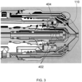
- an auxiliary vent line 404 that is connected to a valve and a flow meter is attached to the nozzle 110 to identify the nozzle 110.
- the valve is opened prior to plasma arc ignition and the auxiliary vent line flow rate is measured by a signal device 202 as a function of plasma pressure during a purge cycle. Therefore, the measured flow rate serves as an identification of the nozzle 110.
- one or more uniquely sized metering holes can be drilled into the outer retain cap to identify the cap once it is installed in the torch 100. The size of each metering hole is configured to uniquely affect the off-valve pressure and/or the flow rate of the shield gas. Therefore, these measurements, taken by a signal device 202 in a pre-flow routine prior to pilot arc ignition, serve to identify the outer retaining cap.
- the processor 206 can be located inside or outside of the plasma arc torch 100. In some embodiments, the processor 206 is housed in the power supply 304. In some embodiments, each of the plasma power supply 304, the motors and drivers 306, the gas console 308, the height controller 310 and the nesting software 312 houses at least one processor for processing data from the signal devices 202 to control the functions of the respective module 304, 306, 308 or 310.
- a signal device 202 associated with the shield 125 of the plasma arc torch 100 can store information about the type and composition of one or more shield gases suitable for use with the shield 125, along with the optimal flow rate setting of the shield gases. Based on this data, the processor 206 can interact with the gas console 308 to provide the plasma arc torch 100 with the appropriate shield gas at the optimal flow rate.
- Fig. 5 is another exemplary thermal processing system 500 using the communication network 200 of Fig. 2 to influence, control, or otherwise affect the operation of a thermal processing torch, such as the plasma arc torch 100 of Fig. 1 .
- the thermal processing system 500 includes a computerized numeric controller (CNC) 502, a power supply 504, an automatic process controller 508, a torch height controller 512 and a driver system 516, which are similar to the processor 206, the power supply 304, the gas console 308, the height controller 310 and the motor and drivers 306, respectively, of the operating system 400.
- the thermal processing system 500 includes a cutting table 520,
- signal devices 202 associated with two sets of physically identical (or at least substantially identical) consumables are encoded with different consumable information and installed into two different torches.
- a signal device for the nozzle of one torch can be encoded with Serial Number A while another signal device for the nozzle of a second torch can be encoded with Serial Number B, even though the two nozzles are manufactured to identical design specifications.
- the nozzles are installed into the respective torches.
- the two torches are installed into their respective thermal processing systems, and the receiver 204 of each thermal processing system can receive consumable data from the signal device 202 of each torch.
- the spacing between the receiver and the various signal devices with which the receiver communicates is typically unobstructed by other components (i.e., little or no material (e.g., no metal material) is disposed in the spacing) to enable or improve communication capabilities between the torch body RFID reader 1204a and the signal devices with which is communicates. That is, obstructions (e.g., metal pieces) in between a receiver and signal devices can inhibit (e.g., prevent) effective communication between the devices, so such obstructions are typically avoided.
- the various signal devices can provide information associated with the consumable on which they are installed to the torch (e.g., the receivers on the torch) that can be used for torch system setup and use. For example, in some embodiments, using the signal devices, a torch system can identify the particular combination of consumables attached to the torch in order to automatically program torch operating parameters for use. The signal devices can also be used to provide a variety of other types of information to the torch system.
- the operating parameters can be communicated (e.g., sent) to a control device of the processing system (906).
- the signal device e.g., readable data tag
- the receiver e.g., the data reading device
- the data tag is an RFID tag and is placed in wireless communication (e.g., near-field communication) by which the data reading device can read the operating parameters from the data tag and transmit the information (e.g., operating parameters) to the thermal processing system.
- the thermal processing machine As a result of transferring information (e.g., operating parameters, instructions, or programs) from the readable storage device to the data reading device, an operator of the thermal processing machine is not required to manually input as many operating parameters that would be required if the operating data was not transferred. That is, in some aspects, using the method 900 of using consumable components having readable data tags can permit automated or semi-automated setup and operation of the thermal processing machine.
- information e.g., operating parameters, instructions, or programs
- the methods of transferring information from a signal device of a consumable to a processing system can be executed in combination with methods for identifying consumables based on physical features of consumables.
- one consumable installed into a torch can include a signal device configured to transfer information to the torch system and another consumable installed into the torch can be identified using physical features of the consumable.
- changes in fluid flow in or around various consumables can be monitored and used in order to identify consumables installed in the torch
- an example method (1000) for providing information (e.g., an operating parameter) to a thermal processing system (e.g., a cutting or welding system) using a replaceable consumable component having a readable data storage device includes first facilitating communication (e.g., wired or wireless communication) between the readable data storage device and a data reading device (e.g., the receiver 204 or the receivers 1204a-b) of the cutting or welding system (1002).
- the readable data storage device can be in the form of an RFID tag and can be placed in wireless communication (e.g., near-field communication) with the readable data storage device.
- information e.g., operating data at least partially defining the operating parameter
- the operating data is typically configured to affect an operation of the cutting or welding system.
- dividing or distributing data onto different consumable components By dividing or distributing data onto different consumable components, less data is typically required to be stored on a single signal device which can result in easier to configure, program, and manage signal devices. Additionally, dividing data onto different consumable components is expected to create a more versatile and customizable thermal processing system as a result of different consumable components being able to be mixed and matched in various different configurations while properly providing adequate operating parameters to the torch system.
- a rewritable data storage device is typically able to add new data after the initial writing of data (e.g., with or without deleting or overwriting other data present on the data storage device).
- the rewritable data storage device is typically able to have new data written while disposed within the torch.
- the operation configuration includes the consumable component being installed within a torch of the thermal processing system ready for use.
- the operation configuration includes the thermal processing system being turned on for operation (e.g., being used).
- the operation configuration can include the torch being in use (e.g., undergoing a processing (e.g., cutting) operation in the field).
- the information can be written to the data storage device (1104).
- the data writing device transmits (writes) information to the data storage device.
- the information transmitted to the rewritable storage device can be associated with the thermal processing system, the torch in which the consumable is installed, or a previous use (e.g., a cutting or welding operation) of the replaceable consumable component in or on which the rewritable storage device in installed.
- the information can include information relating to the frequency of use (e.g., how many cutting or welding operations for which the replaceable consumable component has been used over a given time), relating to a number (e.g., a total number) of cutting cycles for which the replaceable consumable component has been used, or relating to a time duration of the previous use of the replaceable consumable component (i.e., how long the torch was in operation during the previous use.
- the frequency of use e.g., how many cutting or welding operations for which the replaceable consumable component has been used over a given time
- a number e.g., a total number
- a time duration of the previous use of the replaceable consumable component i.e., how long the torch was in operation during the previous use.
- the information can relate to the operating parameters of the thermal processing machine during the previous use of the replaceable consumable component. In some cases, the information relates to a failure or error of the torch, consumable, or thermal processing system during the previous use. In some cases, the thermal processing system is configured to periodically (e.g., repeatedly or continually) write data to the rewritable storage device while the consumable is disposed (e.g., operationally installed) within the torch (e.g., during use of the torch). Such information written to the data storage device can potentially be used for various purposes.
- the information could be used to track usage in order to troubleshoot the machine, in order to review and handle warranty issues (e.g., by being able to observe how an operator was previous using the consumable and thermal processing system prior to inquiring about a warranty), or in order to predict the end of life of the consumable.
- Figs. 6A and 6B are flow diagrams illustrating exemplary operations of the communication network 200 of Fig. 2 .
- Fig. 6A illustrates an exemplary process for assembling thermal processing torches to include one or more consumables and signal devices 202.
- two consumables are provided, with both consumables manufactured based on the same, or substantially the same, physical specifications.
- the two consumables have identical, or substantially identical, physical characteristics.
- a signal device 202 such as an RFID tag, can be coupled to each of the two consumables.
- Each signal device 202 can be located on or within the body of the corresponding consumable.
- the signal device 202 for each consumable is encoded with data that can be used to determine system configuration settings for operating the corresponding torch.
- one consumable can be encoded with data A while the other consumable can be encoded with data B, where data A and data B can be used to set one or more operating parameters of the respective thermal processing systems for operating the respective torches.
- data A and data B include different serial numbers assigned to the respective consumables, which correlate to different values for setting the operating parameters of the thermal processing systems.
- Exemplary operating parameters associated with a thermal processing system include a height of the torch above a workpiece, a flow rate of a plasma gas through the torch and a cutting program for processing a workpiece using the torch.
- each consumable manufactured at step 602, along with its respective signal devices 202 is assembled into a torch.
- another receiver 204 can read data B from the signal device 202 of the consumable of the second torch.
- the receivers 204 of the thermal processing systems forward the data to the respective CNC's of the thermal processing systems, which set and/or adjust certain parameters of the corresponding thermal processing systems based on the received data to operate the corresponding torches.
- the difference in the encoded data for the two consumables translates to different values for setting the operating parameters of the thermal processing systems, even though the consumables are physically identical to each other.
- the thermal processing systems assign the same values to the operating parameters despite the dissimilarity in the encoded data.
- the invention described herein is not only applicable to plasma cutting devices, but also welding-type systems and other thermal processing systems.
- the invention described herein is configured to operate with a variety of cutting technologies, including, but not limited to, plasma arc, laser, oxy fuel, and/or water-jet technologies.
- the signal devices 202 can be coupled to one or more consumables configured to operate with one or more of the cutting technologies.
- the processor 206 using information transmitted by the signal devices 202, can determine whether the consumables installed in a torch are compatible with the specific cutting technology. In some embodiments, based on the selected cutting technology and the consumable information, the processor 206 can set or adjust operating parameters accordingly, such as the height of the cutting head above the workpiece, which can vary depending on the cutting technology and the consumables.
- the signal devices 202 are attached to consumables of a water-jet system, such as to a water-jet nozzle, an abrasive-jet nozzle, a mixing tube used to mix abrasive particles with fluid, and/or one or more valves and filters.
- a signal device 202 associated with an abrasive-jet nozzle can identify, for example, the types of abrasives suitable for use with the nozzle, the amount of pressure in the pressurized fluid that can be fed to the nozzle, and can also indicate other consumables that are suitable for use with a particular nozzle. Identification of particular consumable set combinations for a given water-jet system can also be performed, to verify compatibility with a given system or to limit operating conditions and parameters, such as maximum pressure or flow settings, or abrasive types or amounts.
- thermal cutting systems e.g., plasma arc cutting torches
- thermal cutting systems can also include devices and features that enable detection (e.g., identification) of consumable components installed within the torch by directing a gas flow through the torch (e.g., through a feature of the consumable component) and detecting the manner in which the gas flow is altered as it flows through the torch and the consumable component.
- a gas flow is directed through features (e.g., flow-restriction elements including vent holes or gas exit orifices) arranged on a consumable (e.g., a nozzle).
- the size of the flow-restriction elements, and therefore the consumable itself can be estimated (e.g., identified).
- Some or all of these components can be in communication (e.g., wireless or wired communication) with a control unit (e.g., a processor within a torch system control unit) for monitoring and controlling the gas delivery system.
- a control unit e.g., a processor within a torch system control unit
- gas flows can exit the torch from one or more different areas. For example, when a gas flow enters the torch head 701, a gas stream G1 is typically expelled out from the torch head (e.g., via the nozzle orifice).
- the gas stream G1 generally includes gas that would typically be used to generate a plasma stream and process a material.
- a second gas stream G2 can be emitted from the torch via the vent system based on whether or not certain components of the vent system (e.g., the vent off-valve 716) are opened or closed.
- a gas stream G2 is emitted from the torch head when the vent off-valve 716 is open.
- the gas stream G2 can be caused by gas flowing within the various flow channels and orifices within the torch head (e.g., out of a vent hole in a consumable (e.g., a nozzle)).
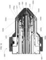
- a torch 800 includes a plasma chamber 802 located at an end of a consumable (e.g., nozzle) 803 having one or more flow-restriction elements (e.g., a nozzle exit orifice 805 or a nozzle vent hole 807).
- the plasma chamber 802 can be fluidly connected to a pressure sensor (e.g., the torch plasma plenum pressure sensor 714) so that gas pressure within the plasma chamber 802 and/or the plasma plenum 806 can be monitored and measured.
- the plasma chamber 802 is fluidly connected to the pressure sensor via the plasma plenum 806 fluidly connected to a vent line 809.
Landscapes
- Engineering & Computer Science (AREA)
- Physics & Mathematics (AREA)
- Plasma & Fusion (AREA)
- Mechanical Engineering (AREA)
- Optics & Photonics (AREA)
- Spectroscopy & Molecular Physics (AREA)
- Arc Welding In General (AREA)
- Plasma Technology (AREA)
- General Factory Administration (AREA)
- Numerical Control (AREA)
- Arc Welding Control (AREA)
Applications Claiming Priority (6)
| Application Number | Priority Date | Filing Date | Title |
|---|---|---|---|
| US13/439,259 US10455682B2 (en) | 2012-04-04 | 2012-04-04 | Optimization and control of material processing using a thermal processing torch |
| US13/560,059 US20130263420A1 (en) | 2012-04-04 | 2012-07-27 | Optimization and Control of Material Processing Using a Thermal Processing Torch |
| US13/838,919 US10486260B2 (en) | 2012-04-04 | 2013-03-15 | Systems, methods, and devices for transmitting information to thermal processing systems |
| PCT/US2013/034572 WO2013151886A2 (en) | 2012-04-04 | 2013-03-29 | Systems, methods, and devices for transmitting information to thermal processing systems |
| EP13716665.8A EP2835041B1 (de) | 2012-04-04 | 2013-03-29 | Systeme, verfahren und vorrichtungen zur übertragung von informationen an wärmeverarbeitungssysteme |
| EP18207623.2A EP3518629B1 (de) | 2012-04-04 | 2013-03-29 | Systeme, verfahren und vorrichtungen zur übertragung von informationen an wärmeverarbeitungssysteme |
Related Parent Applications (2)
| Application Number | Title | Priority Date | Filing Date |
|---|---|---|---|
| EP13716665.8A Division EP2835041B1 (de) | 2012-04-04 | 2013-03-29 | Systeme, verfahren und vorrichtungen zur übertragung von informationen an wärmeverarbeitungssysteme |
| EP18207623.2A Division EP3518629B1 (de) | 2012-04-04 | 2013-03-29 | Systeme, verfahren und vorrichtungen zur übertragung von informationen an wärmeverarbeitungssysteme |
Publications (2)
| Publication Number | Publication Date |
|---|---|
| EP4397431A2 true EP4397431A2 (de) | 2024-07-10 |
| EP4397431A3 EP4397431A3 (de) | 2024-10-23 |
Family
ID=48096321
Family Applications (3)
| Application Number | Title | Priority Date | Filing Date |
|---|---|---|---|
| EP18207623.2A Active EP3518629B1 (de) | 2012-04-04 | 2013-03-29 | Systeme, verfahren und vorrichtungen zur übertragung von informationen an wärmeverarbeitungssysteme |
| EP24178117.8A Pending EP4397431A3 (de) | 2012-04-04 | 2013-03-29 | Systeme, verfahren und vorrichtungen zur übertragung von informationen an thermische verarbeitungssysteme |
| EP13716665.8A Active EP2835041B1 (de) | 2012-04-04 | 2013-03-29 | Systeme, verfahren und vorrichtungen zur übertragung von informationen an wärmeverarbeitungssysteme |
Family Applications Before (1)
| Application Number | Title | Priority Date | Filing Date |
|---|---|---|---|
| EP18207623.2A Active EP3518629B1 (de) | 2012-04-04 | 2013-03-29 | Systeme, verfahren und vorrichtungen zur übertragung von informationen an wärmeverarbeitungssysteme |
Family Applications After (1)
| Application Number | Title | Priority Date | Filing Date |
|---|---|---|---|
| EP13716665.8A Active EP2835041B1 (de) | 2012-04-04 | 2013-03-29 | Systeme, verfahren und vorrichtungen zur übertragung von informationen an wärmeverarbeitungssysteme |
Country Status (9)
| Country | Link |
|---|---|
| US (2) | US10486260B2 (de) |
| EP (3) | EP3518629B1 (de) |
| JP (2) | JP6251723B2 (de) |
| KR (1) | KR101897319B1 (de) |
| CN (1) | CN104472021B (de) |
| AU (1) | AU2013243710B2 (de) |
| BR (1) | BR112014024907A2 (de) |
| RU (1) | RU2649906C2 (de) |
| WO (1) | WO2013151886A2 (de) |
Families Citing this family (48)
| Publication number | Priority date | Publication date | Assignee | Title |
|---|---|---|---|---|
| US9481050B2 (en) | 2013-07-24 | 2016-11-01 | Hypertherm, Inc. | Plasma arc cutting system and persona selection process |
| US10455682B2 (en) | 2012-04-04 | 2019-10-22 | Hypertherm, Inc. | Optimization and control of material processing using a thermal processing torch |
| US10486260B2 (en) * | 2012-04-04 | 2019-11-26 | Hypertherm, Inc. | Systems, methods, and devices for transmitting information to thermal processing systems |
| US9782852B2 (en) | 2010-07-16 | 2017-10-10 | Hypertherm, Inc. | Plasma torch with LCD display with settings adjustment and fault diagnosis |
| US9395715B2 (en) | 2012-04-04 | 2016-07-19 | Hypertherm, Inc. | Identifying components in a material processing system |
| US11783138B2 (en) * | 2012-04-04 | 2023-10-10 | Hypertherm, Inc. | Configuring signal devices in thermal processing systems |
| US9672460B2 (en) | 2012-04-04 | 2017-06-06 | Hypertherm, Inc. | Configuring signal devices in thermal processing systems |
| US9737954B2 (en) | 2012-04-04 | 2017-08-22 | Hypertherm, Inc. | Automatically sensing consumable components in thermal processing systems |
| US9144882B2 (en) | 2012-04-04 | 2015-09-29 | Hypertherm, Inc. | Identifying liquid jet cutting system components |
| US20150332071A1 (en) | 2012-04-04 | 2015-11-19 | Hypertherm, Inc. | Configuring Signal Devices in Thermal Processing Systems |
| US9643273B2 (en) | 2013-10-14 | 2017-05-09 | Hypertherm, Inc. | Systems and methods for configuring a cutting or welding delivery device |
| US12275082B2 (en) | 2013-11-13 | 2025-04-15 | Hypertherm, Inc. | Consumable cartridge for a plasma arc cutting system |
| WO2015094973A1 (en) * | 2013-12-20 | 2015-06-25 | Hypertherm, Inc. | Identifying liquid jet cutting system components |
| US9446472B2 (en) * | 2014-03-05 | 2016-09-20 | Lincoln Global, Inc. | System and method for integrated controller |
| US10786924B2 (en) | 2014-03-07 | 2020-09-29 | Hypertherm, Inc. | Waterjet cutting head temperature sensor |
| WO2015134966A1 (en) * | 2014-03-07 | 2015-09-11 | Hypertherm, Inc. | Liquid pressurization pump and systems with data storage |
| US20150269603A1 (en) | 2014-03-19 | 2015-09-24 | Hypertherm, Inc. | Methods for Developing Customer Loyalty Programs and Related Systems and Devices |
| US10486261B2 (en) | 2014-03-28 | 2019-11-26 | Lincoln Global, Inc. | Plasma system with integrated power supply, motion control, gas control and torch |
| WO2016014834A1 (en) * | 2014-07-23 | 2016-01-28 | Hypertherm, Inc. | Configuring signal devices in thermal processing systems |
| US10149376B2 (en) * | 2014-12-11 | 2018-12-04 | Hypertherm, Inc. | Water injection and venting of a plasma arc torch |
| WO2016138524A1 (en) * | 2015-02-27 | 2016-09-01 | Hypertherm, Inc. | Automatically sensing consumable components in thermal processing systems |
| US10137522B2 (en) | 2015-07-02 | 2018-11-27 | Lincoln Global, Inc. | Adaptive plasma cutting system and method |
| EP4243575A3 (de) * | 2015-08-04 | 2023-10-25 | Hypertherm, Inc. | Kartusche für einen flüssigkeitsgekühlten plasmabogenbrenner |
| JP6063014B1 (ja) * | 2015-08-31 | 2017-01-18 | ファナック株式会社 | 溶接チップおよびノズルを交換するためのチャック装置、およびロボット |
| US10440808B2 (en) | 2015-11-17 | 2019-10-08 | Southwest Research Institute | High power impulse plasma source |
| US10413991B2 (en) * | 2015-12-29 | 2019-09-17 | Hypertherm, Inc. | Supplying pressurized gas to plasma arc torch consumables and related systems and methods |
| US10354845B2 (en) * | 2016-02-18 | 2019-07-16 | Southwest Research Institute | Atmospheric pressure pulsed arc plasma source and methods of coating therewith |
| WO2018017045A1 (en) * | 2016-07-18 | 2018-01-25 | Victor Equipment Company | Plasma device consumable part change detection |
| US10449615B2 (en) * | 2016-10-31 | 2019-10-22 | Illinois Tool Works Inc. | Hybrid welding modules |
| CN106671608B (zh) * | 2017-01-03 | 2018-07-24 | 珠海艾派克微电子有限公司 | 一种序列号调整方法、装置、耗材芯片及成像盒 |
| CN110383956B (zh) | 2017-02-09 | 2022-11-18 | 海别得公司 | 用于等离子弧焊炬筒的涡流环和接触元件 |
| US10674593B2 (en) * | 2017-09-15 | 2020-06-02 | Lincoln Global, Inc. | Plasma processing system with consumable identification |
| WO2019105539A1 (de) | 2017-11-29 | 2019-06-06 | Telsonic Holding Ag | Ultraschallbearbeitungsvorrichtung, verfahren zur konfiguration einer ultraschallbearbeitungsvorrichtung, system mit solcher ultraschallbearbeitungsvorrichtung |
| US11267069B2 (en) * | 2018-04-06 | 2022-03-08 | The Esab Group Inc. | Recognition of components for welding and cutting torches |
| US10625359B2 (en) * | 2018-04-06 | 2020-04-21 | The Esab Group Inc. | Automatic identification of components for welding and cutting torches |
| US20190358730A1 (en) * | 2018-04-06 | 2019-11-28 | The Esab Group Inc. | Automatic identification of components for welding and cutting torches |
| DE102018003123B4 (de) * | 2018-04-17 | 2025-10-16 | Bräuer Systemtechnik GmbH | Verwendung einer Anordnung zur Überwachung von Werkzeugen bei der Bearbeitung rotationssymmetrischer Werkstücke |
| WO2020092567A1 (en) | 2018-10-30 | 2020-05-07 | Hypertherm, Inc. | Automated consumable exchangers |
| US20210060680A1 (en) * | 2019-08-28 | 2021-03-04 | Lincoln Global, Inc. | Systems and methods providing coordinated dual power outputs supporting a same welding or auxiliary power process |
| US11664971B2 (en) | 2019-11-13 | 2023-05-30 | The Esab Group Inc. | Encrypted communication between components of welding and cutting systems |
| EP3840541A1 (de) * | 2019-12-20 | 2021-06-23 | Molecular Plasma Group SA | Verbesserte abschirmung für atmosphärendruckplasmastrahlbeschichtungsabscheidung auf einem substrat |
| JP7474610B2 (ja) * | 2020-03-10 | 2024-04-25 | コマツ産機株式会社 | プラズマ切断機、及びその制御方法 |
| US20220032389A1 (en) * | 2020-07-29 | 2022-02-03 | Illinois Tool Works Inc. | Systems and methods for automatic gouge torch activation |
| US11839015B2 (en) | 2021-02-04 | 2023-12-05 | The Esab Group Inc. | Consumables for processing torches |
| EP4399047B1 (de) | 2021-09-10 | 2025-12-10 | Esab Ab | Lesen von markiertem verbrauchsmaterial wie drähte |
| JP2024037425A (ja) | 2022-09-07 | 2024-03-19 | 株式会社Fuji | プラズマ発生装置、および流路監視方法 |
| JP2024128399A (ja) * | 2023-03-10 | 2024-09-24 | 日本特殊陶業株式会社 | プラズマ照射システム、検査装置、及びプラズマ照射器具 |
| WO2024236684A1 (ja) * | 2023-05-15 | 2024-11-21 | 株式会社Fuji | プラズマ発生装置、および配管異常判断方法 |
Family Cites Families (222)
| Publication number | Priority date | Publication date | Assignee | Title |
|---|---|---|---|---|
| AUPQ055999A0 (en) | 1999-05-25 | 1999-06-17 | Silverbrook Research Pty Ltd | A method and apparatus (npage01) |
| US2985050A (en) | 1958-10-13 | 1961-05-23 | North American Aviation Inc | Liquid cutting of hard materials |
| US3010012A (en) * | 1959-12-24 | 1961-11-21 | Air Reduction | Arc welding |
| US3018360A (en) * | 1960-04-25 | 1962-01-23 | Air Reduction | Arc welding torch |
| US3518401A (en) * | 1967-10-04 | 1970-06-30 | Air Reduction | Electric arc pulsing |
| US3602683A (en) | 1969-02-03 | 1971-08-31 | Sumitomo Heavy Industries | Automatic control mechanism for plasma welder |
| US3996070A (en) | 1974-11-22 | 1976-12-07 | Nasa | Thermocouple installation |
| CH593754A5 (de) | 1976-01-15 | 1977-12-15 | Castolin Sa | |
| JPS57172411A (en) * | 1981-04-15 | 1982-10-23 | Mitsubishi Electric Corp | Numeric controller |
| CA1173784A (en) * | 1981-07-30 | 1984-09-04 | William H. Gauvin | Transferred-arc plasma reactor for chemical and metallurgical applications |
| US5388965A (en) | 1990-10-10 | 1995-02-14 | Friedrich Wilhelm Schwing Gmbh | Sludge pump with monitoring system |
| DE3234345A1 (de) * | 1982-09-16 | 1984-03-22 | Robert Bosch Gmbh, 7000 Stuttgart | Kodiersystem zur erfassung von informationen an werkstuecktraegern und dergleichen |
| JPS6163368A (ja) | 1984-09-03 | 1986-04-01 | Takashi Murata | 被覆ア−ク溶接棒用溶接条件自動設定方法 |
| SE8500714L (sv) * | 1985-02-15 | 1986-05-12 | Esab Ab | Kontaktmunstycke med en skruvlinjeformig passage for en smeltbar svetstrad |
| AT388809B (de) | 1985-10-15 | 1989-09-11 | Avl Verbrennungskraft Messtech | Messanordnung, verfahren zum nullpunktabgleich des differenzdruckumformers in einer messanordnung sowie messblende fuer eine messanordnung zur durchflussmengenmessung von fluid-, vorzugsweise gasstroemen |
| US4742470A (en) * | 1985-12-30 | 1988-05-03 | Gte Valeron Corporation | Tool identification system |
| US5050106A (en) * | 1987-10-07 | 1991-09-17 | Omron Tateisi Electronics Co. | Article recognizing system |
| US4929811A (en) * | 1988-12-05 | 1990-05-29 | The Lincoln Electric Company | Plasma arc torch interlock with disabling control arrangement system |
| US5071168A (en) | 1989-01-25 | 1991-12-10 | Shamos Morris H | Patient identification system |
| US5018670A (en) | 1990-01-10 | 1991-05-28 | Possis Corporation | Cutting head for water jet cutting machine |
| JPH04201124A (ja) * | 1990-11-30 | 1992-07-22 | Mitsubishi Electric Corp | 放電加工用電極およびその装置 |
| US5099226A (en) * | 1991-01-18 | 1992-03-24 | Interamerican Industrial Company | Intelligent security system |
| US5208436A (en) | 1991-04-12 | 1993-05-04 | The Lincoln Electric Company | Plasma torch with identification circuit |
| US5440477A (en) | 1991-05-20 | 1995-08-08 | Creative Pathways, Inc. | Modular bottle-mounted gas management system |
| JPH05154732A (ja) | 1991-11-30 | 1993-06-22 | Nippei Toyama Mechatronics:Kk | 工具交換機構を備えた加工装置 |
| US5309683A (en) | 1992-01-28 | 1994-05-10 | Sandroid Systems, Inc. | Recovery system |
| JPH05327582A (ja) * | 1992-05-19 | 1993-12-10 | Fujitsu Ltd | 携帯電話機のプログラムメモリ書き替え方式 |
| US5390964A (en) * | 1992-10-01 | 1995-02-21 | Gray, Jr.; Lawrence C. | Labeled pipe fitting and method |
| AUPM470994A0 (en) * | 1994-03-25 | 1994-04-21 | Commonwealth Scientific And Industrial Research Organisation | Plasma torch condition monitoring |
| US5556562A (en) * | 1994-12-12 | 1996-09-17 | J. W. Harris Co., Inc. | Welding assembly |
| US5500512A (en) | 1994-12-16 | 1996-03-19 | General Electric Company | Welding wire verification control system |
| US5643058A (en) | 1995-08-11 | 1997-07-01 | Flow International Corporation | Abrasive fluid jet system |
| US5653264A (en) | 1995-10-13 | 1997-08-05 | Atkinson; Louis D. | Fluid orifice device having encoded orifice size indicia |
| US7115123B2 (en) * | 1996-01-05 | 2006-10-03 | Thermage, Inc. | Handpiece with electrode and non-volatile memory |
| DE19626941A1 (de) * | 1996-07-04 | 1998-01-08 | Castolin Sa | Verfahren zum Beschichten oder Schweißen leicht oxidierbarer Werkstoffe sowie Plasmabrenner dafür |
| US5994663A (en) | 1996-10-08 | 1999-11-30 | Hypertherm, Inc. | Plasma arc torch and method using blow forward contact starting system |
| US5860849A (en) | 1997-03-25 | 1999-01-19 | Huffman Corp | Liquid abrasive jet focusing tube for making non-perpendicular cuts |
| US6091048A (en) | 1997-05-16 | 2000-07-18 | Illinois Tool Works Inc. | Welding machine with automatic parameter setting |
| JPH11285831A (ja) | 1998-04-07 | 1999-10-19 | Koike Sanso Kogyo Co Ltd | 切断装置 |
| US6047579A (en) * | 1998-04-17 | 2000-04-11 | The Minster Machine Company | RF tag attached to die assembly for use in press machine |
| AT409239B (de) | 1998-05-13 | 2002-06-25 | Fronius Schweissmasch | Verfahren zum steuern eines schweissgerätes und steuervorrichtung hierfür |
| US6130407A (en) * | 1998-07-29 | 2000-10-10 | Tregaskiss, Ltd. | Arc welding torch |
| US6326583B1 (en) | 2000-03-31 | 2001-12-04 | Innerlogic, Inc. | Gas control system for a plasma arc torch |
| ATE254739T1 (de) * | 1999-05-31 | 2003-12-15 | Binzel Alex Schweisstech | Brennerkopf eines lichtbogenschweiss- oder - schneidbrenners mit formschlüssig gehaltener kontaktdüse |
| US7032814B2 (en) * | 1999-06-21 | 2006-04-25 | Lincoln Global, Inc. | Coded welding consumable |
| CA2439213C (en) | 1999-06-21 | 2006-10-10 | Lincoln Global, Inc. | Coded and electronically tagged welding wire |
| US6267291B1 (en) * | 1999-06-21 | 2001-07-31 | Lincoln Global, Inc. | Coded and electronically tagged welding wire |
| US8141240B2 (en) | 1999-08-04 | 2012-03-27 | Super Talent Electronics, Inc. | Manufacturing method for micro-SD flash memory card |
| US6409476B2 (en) | 1999-08-06 | 2002-06-25 | Djax Corporation | Pumpjack dynamometer and method |
| JP4387010B2 (ja) | 1999-11-10 | 2009-12-16 | 株式会社ディスコ | 切削装置 |
| JP2001141532A (ja) | 1999-11-15 | 2001-05-25 | Smc Corp | 絞り構造体及び絞り構造体を組み込む流量計 |
| US6259059B1 (en) * | 1999-12-21 | 2001-07-10 | Lincoln Global, Inc. | Arc welder and torch for same |
| DE10000435A1 (de) | 2000-01-10 | 2001-07-12 | Mann & Hummel Filter | Verfahren und Vorrichtung zur Überwachung wartungsintensiver Austauschteile an einem Aggregat |
| JP3730468B2 (ja) * | 2000-01-13 | 2006-01-05 | 小池酸素工業株式会社 | トーチ角度設定装置 |
| FR2803978A1 (fr) | 2000-01-17 | 2001-07-20 | Air Liquide | Torche a plasma avec systeme d'identification de la tete, de l'electrode ou de la tuyere |
| US6772040B1 (en) | 2000-04-10 | 2004-08-03 | Hypertherm, Inc. | Centralized control architecture for a plasma arc system |
| DE10061691B4 (de) * | 2000-12-12 | 2004-12-30 | Agie S.A., Losone | Vorrichtung und Verfahren zur Detektion einer Bearbeitungselektrode einer Werkzeugmaschine |
| TW531976B (en) | 2001-01-11 | 2003-05-11 | Hanex Co Ltd | Communication apparatus and installing structure, manufacturing method and communication method |
| US6903301B2 (en) | 2001-02-27 | 2005-06-07 | Thermal Dynamics Corporation | Contact start plasma arc torch and method of initiating a pilot arc |
| US6717096B2 (en) | 2001-02-27 | 2004-04-06 | Thermal Dynamics Corporation | Dual mode plasma arc torch |
| US20020194064A1 (en) | 2001-06-01 | 2002-12-19 | Parry Travis J. | Methods and apparatus for promoting use of consumable goods in imaging devices |
| JP2003025176A (ja) | 2001-07-11 | 2003-01-29 | Incs Inc | 工具管理システム |
| US6851627B2 (en) | 2001-07-31 | 2005-02-08 | Flow International Corporation | Multiple segment high pressure fluidjet nozzle and method of making the nozzle |
| JP2003048134A (ja) | 2001-08-07 | 2003-02-18 | Incs Inc | 工具管理システム |
| EP2305143B1 (de) | 2001-08-08 | 2016-11-09 | Stryker Corporation | Chirurgisches Werkzeugsystem mit Bestandteilen zur Durchführung induktiver Datenübertragung |
| US8204618B2 (en) | 2008-03-24 | 2012-06-19 | Hypertherm, Inc. | Method and apparatus for operating an automated high temperature thermal cutting system |
| US6688947B2 (en) | 2002-02-05 | 2004-02-10 | The Johns Hopkins University | Porous, lubricated nozzle for abrasive fluid suspension jet |
| US6693252B2 (en) | 2002-04-01 | 2004-02-17 | Illinois Tool Works Inc. | Plasma MIG welding with plasma torch and MIG torch |
| WO2003089183A1 (en) * | 2002-04-19 | 2003-10-30 | Thermal Dynamics Corporation | Plasma arc torch |
| US6967304B2 (en) | 2002-04-29 | 2005-11-22 | Cyber Materials Llc | Feedback enhanced plasma spray tool |
| US6781085B2 (en) | 2002-10-09 | 2004-08-24 | Illinois Tool Works Inc. | Method and apparatus of coordinating operating modes of a plasma cutter and a power supply |
| US20040106101A1 (en) | 2002-12-02 | 2004-06-03 | Evans Daron G. | System and method for quality control of a shipped neural cell culture on a microelectrode array |
| JP2004237321A (ja) | 2003-02-06 | 2004-08-26 | Komatsu Sanki Kk | プラズマ加工装置 |
| JP2004295348A (ja) | 2003-03-26 | 2004-10-21 | Mori Seiki Co Ltd | 工作機械の保守管理システム |
| US6729468B1 (en) | 2003-03-28 | 2004-05-04 | Thomas N Dobmeier | Circular saw blade holder |
| US20110163857A1 (en) | 2003-04-09 | 2011-07-07 | Visible Assets, Inc. | Energy Harvesting for Low Frequency Inductive Tagging |
| JP2004351449A (ja) * | 2003-05-28 | 2004-12-16 | Komatsu Sanki Kk | プラズマ切断装置及びそれの制御装置 |
| US6995545B2 (en) | 2003-08-18 | 2006-02-07 | Mks Instruments, Inc. | Control system for a sputtering system |
| US6960737B2 (en) | 2003-08-29 | 2005-11-01 | Thermal Dynamics Corporation | Gas flow pre-charge for a plasma arc torch |
| US7034244B2 (en) | 2003-09-03 | 2006-04-25 | Illinois Tool Works Inc. | Method and apparatus of coordinating operational feedback in a plasma cutter |
| FI20031331A7 (fi) * | 2003-09-17 | 2005-03-18 | Tomion Oy | Jäähdytetty plasmapoltin ja menetelmä polttimen jäähdyttämiseksi |
| US7186944B2 (en) * | 2003-09-18 | 2007-03-06 | Illinois Tool Works Inc. | Method and apparatus for autodetection of plasma torch consumables |
| US6992262B2 (en) | 2003-10-09 | 2006-01-31 | Illinois Tool Works Inc. | Method and apparatus for localized control of a plasma cutter |
| US8395076B2 (en) | 2003-11-06 | 2013-03-12 | Illinois Tool Works Inc. | One-piece consumable assembly |
| US20050109738A1 (en) | 2003-11-21 | 2005-05-26 | Hewett Roger W. | Color coding of plasma arc torch parts and part sets |
| US7030337B2 (en) | 2003-12-19 | 2006-04-18 | Honeywell International, Inc. | Hand-held laser welding wand having removable filler media delivery extension tips |
| US7180422B2 (en) * | 2003-12-29 | 2007-02-20 | Intel Corporation | Asset management methods and apparatus |
| US7755484B2 (en) | 2004-02-12 | 2010-07-13 | Avery Dennison Corporation | RFID tag and method of manufacturing the same |
| FR2868718B1 (fr) | 2004-04-08 | 2007-06-29 | 3D Ind Soc Par Actions Simplif | Dispositif de decoupe au laser pour detourer, ajourer, poinconner |
| US8759715B2 (en) * | 2004-10-06 | 2014-06-24 | Lincoln Global, Inc. | Method of AC welding with cored electrode |
| US20080066596A1 (en) * | 2004-05-20 | 2008-03-20 | Komatsu Insustries Corporation | Cutting Machine and Method of Moving Cutting Head |
| JP4266206B2 (ja) * | 2004-05-24 | 2009-05-20 | 小池酸素工業株式会社 | プラズマトーチの寿命検出装置 |
| KR20040101948A (ko) | 2004-05-31 | 2004-12-03 | (주)케이.씨.텍 | 표면세정용 승화성 고체입자 분사용 노즐 및 이를 이용한 세정방법 |
| US7645960B2 (en) * | 2004-06-18 | 2010-01-12 | Lincoln Global, Inc. | Coded welding consumable |
| US20060020415A1 (en) | 2004-07-23 | 2006-01-26 | Hardwicke Canan U | Sensor and method for making same |
| JP4771043B2 (ja) | 2004-09-06 | 2011-09-14 | 日本電気株式会社 | 薄膜半導体素子及びその駆動回路並びにそれらを用いた装置 |
| US7323659B2 (en) | 2004-09-28 | 2008-01-29 | Illinois Tool Works Inc. | System and method of precise wire feed control in a welder |
| US7115833B2 (en) | 2004-11-03 | 2006-10-03 | The Esab Group, Inc. | Metering system and method for supplying gas to a torch |
| US7375302B2 (en) * | 2004-11-16 | 2008-05-20 | Hypertherm, Inc. | Plasma arc torch having an electrode with internal passages |
| US8263896B2 (en) | 2005-01-03 | 2012-09-11 | Illinois Tool Works Inc. | Automated determination of plasma torch operating mode |
| US7358458B2 (en) * | 2005-01-25 | 2008-04-15 | Lincoln Global, Inc. | Methods and apparatus for tactile communication in an arc processing system |
| US7301124B2 (en) | 2005-01-26 | 2007-11-27 | Illinois Tool Works Inc. | System and method for coordinating wire feeder motor operation |
| US20060163220A1 (en) | 2005-01-27 | 2006-07-27 | Brandt Aaron D | Automatic gas control for a plasma arc torch |
| JP4677241B2 (ja) * | 2005-01-31 | 2011-04-27 | 富士通株式会社 | 情報読取装置、情報読取システムおよびrfidタグ |
| US7335854B2 (en) | 2005-03-11 | 2008-02-26 | Illinois Tool Works Inc. | Method and system of determining wire feed speed |
| JP4707421B2 (ja) | 2005-03-14 | 2011-06-22 | 東京エレクトロン株式会社 | 処理装置,処理装置の消耗部品管理方法,処理システム,処理システムの消耗部品管理方法 |
| US7411154B2 (en) | 2005-03-24 | 2008-08-12 | Illinois Tool Works Inc. | Control panel for a welding-type apparatus |
| US20080001752A1 (en) * | 2005-04-21 | 2008-01-03 | Skyetek, Inc. | System and method for securing rfid tags |
| US20060289679A1 (en) | 2005-06-27 | 2006-12-28 | Johnson Kaj A | Modular sprayer |
| FR2887938A1 (fr) | 2005-07-04 | 2007-01-05 | Alcatel Sa | Ligne de vide et procede de surveillance d'une telle ligne |
| CN101262990B (zh) | 2005-08-04 | 2013-03-27 | 美国派尔(PaR)系统有限公司 | 对流体喷射装置的补偿 |
| US8431862B2 (en) * | 2005-08-25 | 2013-04-30 | Lincoln Global, Inc. | Torch for electric arc welding system |
| GB0518458D0 (en) | 2005-09-09 | 2005-10-19 | Boc Group Plc | Arc welding |
| US8686318B2 (en) | 2005-10-07 | 2014-04-01 | Illinois Tool Works Inc. | Wireless tracking and inventory monitoring for welding-type devices |
| US9138825B2 (en) | 2005-10-07 | 2015-09-22 | Illinois Tool Works Inc. | Wireless communication system for welding-type devices |
| US7680625B2 (en) * | 2005-11-14 | 2010-03-16 | Macsema, Inc. | Systems and methods for monitoring system performance |
| EP1958172B1 (de) | 2005-12-09 | 2014-11-12 | Tego Inc. | Mehrfaches funkfrequenznetzwerkknoten-rfid-etikett |
| US8115136B2 (en) | 2006-02-17 | 2012-02-14 | Hypertherm, Inc. | Electrode for a contact start plasma arc torch and contact start plasma arc torch employing such electrodes |
| WO2007109636A2 (en) | 2006-03-20 | 2007-09-27 | Monto Kumagai | Rfid-tagged consumer items having personalized event information |
| US8203095B2 (en) * | 2006-04-20 | 2012-06-19 | Materials & Electrochemical Research Corp. | Method of using a thermal plasma to produce a functionally graded composite surface layer on metals |
| US9687931B2 (en) | 2006-12-05 | 2017-06-27 | Lincoln Global, Inc. | System for measuring energy using digitally controlled welding power sources |
| DE102006023232B4 (de) | 2006-05-18 | 2011-04-14 | Hüttinger Elektronik Gmbh + Co. Kg | Plasmaprozessleistungsversorgungssystem mit ereignisgesteuerter Datenspeicherung und Verfahren dazu |
| TWI519988B (zh) * | 2006-07-10 | 2016-02-01 | 安特格利斯公司 | 用以管理流體及具有資訊儲存元件之材料儲存容器的方法及其自動化系統 |
| US20080011821A1 (en) | 2006-07-10 | 2008-01-17 | Daniel Measurement And Control, Inc. | Method and System of Determining Orifice Plate Parameters |
| US9931708B2 (en) | 2006-07-27 | 2018-04-03 | Illinois Tool Works Inc. | Automatic consumable and torch length detection via pressure decay |
| US8710396B2 (en) * | 2006-07-27 | 2014-04-29 | Illinois Tool Works Inc. | Method and apparatus for automatically controlling gas pressure for a plasma cutter |
| KR20090079187A (ko) | 2006-08-03 | 2009-07-21 | 스마트 패키징 쏠루션즈 (에스피에스) | 보안이 향상된 보안 증서, 특히 전자 패스포트 |
| US8620738B2 (en) | 2006-08-31 | 2013-12-31 | Visa U.S.A. Inc | Loyalty program incentive determination |
| US8658941B2 (en) * | 2006-09-07 | 2014-02-25 | Illinois Tool Works Inc. | Wireless system control and inventory monitoring for welding-type devices |
| US7989727B2 (en) | 2006-09-13 | 2011-08-02 | Hypertherm, Inc. | High visibility plasma arc torch |
| US8322624B2 (en) | 2007-04-10 | 2012-12-04 | Feinics Amatech Teoranta | Smart card with switchable matching antenna |
| JP4293229B2 (ja) | 2006-11-16 | 2009-07-08 | ブラザー工業株式会社 | 画像形成装置 |
| US7671294B2 (en) | 2006-11-28 | 2010-03-02 | Vladimir Belashchenko | Plasma apparatus and system |
| US9104195B2 (en) | 2006-12-20 | 2015-08-11 | Lincoln Global, Inc. | Welding job sequencer |
| US8592719B2 (en) * | 2006-12-22 | 2013-11-26 | Illinois Tool Works Inc. | System and method for identifying welding consumable wear |
| US20080156783A1 (en) | 2006-12-29 | 2008-07-03 | Vanden Heuvel Michael L | Portable multi-wire feeder |
| AT504721B1 (de) | 2007-01-11 | 2011-02-15 | Sbi Produktion Techn Anlagen Gmbh | Verfahren zum plasma-punktschweissen von oberflächenvergüteten werkstücken und plasma-brenner |
| EP2022299B1 (de) | 2007-02-16 | 2014-04-30 | Hypertherm, Inc | Gasgekühlte lichtbogen-plasmaschneidbrenner |
| TWI430845B (zh) | 2007-03-16 | 2014-03-21 | Sulzer Metco Ag | 資料管理之裝置及方法 |
| JPWO2008114478A1 (ja) * | 2007-03-19 | 2010-07-01 | パナソニック株式会社 | 溶接装置 |
| RU2354460C2 (ru) | 2007-04-02 | 2009-05-10 | Обшество с ограниченной ответственностью "ПЛАЗМА" (ООО "ПЛАЗМА") | Портативный плазмотрон для напыления и наплавки покрытий |
| US8629373B2 (en) * | 2007-04-19 | 2014-01-14 | Illinois Tool Works Inc. | Synchronized multiple drive wire feed welding system and method |
| US9257264B2 (en) | 2007-04-23 | 2016-02-09 | Plasmology4, Inc. | Harmonic cold plasma devices and associated methods |
| AT505237B1 (de) | 2007-05-25 | 2009-03-15 | Fronius Int Gmbh | Schweissanlage und verfahren zur übertragung von informationen sowie zur beeinflussung von parametern einer schweissanlage |
| US8085150B2 (en) | 2007-05-29 | 2011-12-27 | Rcd Technology Inc | Inventory system for RFID tagged objects |
| KR100935406B1 (ko) | 2007-06-08 | 2010-01-06 | 주식회사 플라즈마트 | 플라즈마 이상 감지 장치와 플라즈마 이상 감지 방법 |
| US8759714B2 (en) * | 2007-07-06 | 2014-06-24 | Illinois Tool Works Inc. | Portable generator and battery charger verification control method and system |
| US7651269B2 (en) | 2007-07-19 | 2010-01-26 | Lam Research Corporation | Temperature probes having a thermally isolated tip |
| WO2009019794A1 (ja) * | 2007-08-06 | 2009-02-12 | Makino Milling Machine Co., Ltd. | 工具ホルダ |
| US8129652B2 (en) | 2007-10-30 | 2012-03-06 | GM Global Technology Operations LLC | Welding stability system and method |
| US8316742B2 (en) * | 2007-12-11 | 2012-11-27 | Kennametal Inc. | Cutting tool with integrated circuit chip |
| US8450646B2 (en) * | 2007-12-18 | 2013-05-28 | Illinois Tool Works Inc. | Retaining head and contact tip for controlling wire contour and contacting point for GMAW torches |
| US8373084B2 (en) | 2007-12-19 | 2013-02-12 | Illinois Tool Works Inc. | Plasma cutter having high power density |
| US8859928B2 (en) | 2007-12-19 | 2014-10-14 | Illinois Tool Works Inc. | Multi-stage compressor in a plasma cutter |
| US8153924B2 (en) | 2007-12-19 | 2012-04-10 | Illinois Tool Works Inc. | Plasma cutter having thermal model for component protection |
| US9040869B2 (en) | 2007-12-19 | 2015-05-26 | Illinois Tool Works Inc. | Plasma cutter having microprocessor control |
| US10479509B2 (en) | 2007-12-21 | 2019-11-19 | Airbus Operations Gmbh | Ventilation system for wide-bodied aircraft |
| US20090212027A1 (en) | 2008-02-21 | 2009-08-27 | Hypertherm, Inc. | Binary Signal Detection |
| US20090222804A1 (en) * | 2008-02-29 | 2009-09-03 | Illinois Tool Works, Inc. | Embedded firmware updating system and method |
| US8212173B2 (en) * | 2008-03-12 | 2012-07-03 | Hypertherm, Inc. | Liquid cooled shield for improved piercing performance |
| JP4911386B2 (ja) | 2008-04-09 | 2012-04-04 | Necフィールディング株式会社 | 保守作業支援システム及びその方法 |
| US8651920B2 (en) | 2008-05-21 | 2014-02-18 | Flow International Corporation | Mixing tube for a waterjet system |
| US8278588B2 (en) | 2008-05-29 | 2012-10-02 | Illinois Tool Works Inc. | System and method for start flow approach control for a proportional valve in a plasma cutter |
| US9539664B2 (en) * | 2008-06-17 | 2017-01-10 | Matthew Fagan | Methods and systems for predictive torch height control |
| WO2010022105A2 (en) | 2008-08-19 | 2010-02-25 | Plextronics, Inc. | Organic light emitting diode products |
| US8338740B2 (en) | 2008-09-30 | 2012-12-25 | Hypertherm, Inc. | Nozzle with exposed vent passage |
| US8338739B2 (en) | 2008-12-22 | 2012-12-25 | Hypertherm, Inc. | Method and apparatus for cutting high quality internal features and contours |
| US8859828B2 (en) | 2009-03-02 | 2014-10-14 | Clariant Corporation | Conversion of sugar, sugar alcohol, or glycerol to valuable chemicals using a promoted zirconium oxide supported catalyst |
| US8272794B2 (en) | 2009-04-29 | 2012-09-25 | Ed Silchenstedt | Material marking system and method incorporating an HMI device |
| FI125409B (fi) | 2009-06-12 | 2015-09-30 | Kemppi Oy | Moduuli hitsauslaitteen ohjaamiseksi, hitsauslaite, hitsausjärjestelmä, menetelmä hitsaajan opastamiseksi, hitsausmenetelmä sekä ohjelmistotuote |
| US8538697B2 (en) | 2009-06-22 | 2013-09-17 | Mark C. Russell | Core sample preparation, analysis, and virtual presentation |
| US8766132B2 (en) | 2009-07-06 | 2014-07-01 | Lincoln Global, Inc. | Synergistic welding and electrode selection and identification method |
| US10423967B2 (en) | 2009-07-28 | 2019-09-24 | Oohdoo, Inc. | System and method for providing advertising content via mobile device docking station |
| US9676050B2 (en) | 2009-11-17 | 2017-06-13 | Illinois Tool Works Inc. | Welding system with lockout mechanism |
| US9737951B2 (en) * | 2010-03-10 | 2017-08-22 | Illinois Tool Works Inc. | Welding wire feeder with multimotor standard |
| JP5370581B2 (ja) | 2010-03-24 | 2013-12-18 | 株式会社村田製作所 | Rfidシステム |
| EP2397257B1 (de) | 2010-06-21 | 2018-01-03 | Omax Corporation | Systeme zur Abrasionsstrahldurchbohrung und zugehörige Verfahren |
| US20140061170A1 (en) * | 2012-04-04 | 2014-03-06 | Hypertherm, Inc | Identifying Thermal Processing Torch Components |
| US8835796B2 (en) * | 2010-07-16 | 2014-09-16 | Hypertherm, Inc. | Diffuser shape vent slots in a hand torch shield castellation |
| US20130263420A1 (en) | 2012-04-04 | 2013-10-10 | Hypertherm, Inc. | Optimization and Control of Material Processing Using a Thermal Processing Torch |
| US10455682B2 (en) | 2012-04-04 | 2019-10-22 | Hypertherm, Inc. | Optimization and control of material processing using a thermal processing torch |
| US20140069895A1 (en) * | 2012-04-04 | 2014-03-13 | Hypertherm, Inc. | Automated cartridge detection for a plasma arc cutting system |
| US10486260B2 (en) | 2012-04-04 | 2019-11-26 | Hypertherm, Inc. | Systems, methods, and devices for transmitting information to thermal processing systems |
| WO2012009634A1 (en) * | 2010-07-16 | 2012-01-19 | Hypertherm, Inc. | Failure event detection in a plasma arc torch |
| JP2012048287A (ja) | 2010-08-24 | 2012-03-08 | Mitsubishi Electric Corp | 部品管理装置、部品管理システム、部品管理方法、および、部品管理プログラム |
| CN103154532B (zh) | 2010-09-13 | 2016-03-16 | 泰克铌水刀有限公司 | 超高压泵 |
| JP5550514B2 (ja) | 2010-10-05 | 2014-07-16 | 三菱重工業株式会社 | 構成品管理システム |
| US8395074B2 (en) | 2010-12-03 | 2013-03-12 | Kaliburn, Inc. | Plasma ARC systems with cutting and marking functions |
| DE102010053584A1 (de) | 2010-12-06 | 2012-06-06 | Andreas Stihl Ag & Co. Kg | Benutzungssperre für ein handgeführtes Arbeitsgerät |
| JP5594118B2 (ja) * | 2010-12-16 | 2014-09-24 | パナソニック株式会社 | アーク溶接装置およびアーク溶接電源装置および溶接用トーチ |
| CN103282754B (zh) | 2011-01-07 | 2015-05-20 | 株式会社村田制作所 | 温度传感器及温度传感器安装结构 |
| US11110538B2 (en) | 2011-03-25 | 2021-09-07 | Illinois Tool Works Inc. | Systems and methods for adjusting multiple settings of a welding power supply |
| JP2012213846A (ja) | 2011-03-30 | 2012-11-08 | Brother Industries Ltd | 切断装置及び保持部材 |
| WO2012153329A1 (en) * | 2011-05-12 | 2012-11-15 | Petratec International Ltd. | Rfid collar |
| AT511213B1 (de) | 2011-05-27 | 2012-10-15 | Fronius Int Gmbh | Verfahren zum ermitteln des anpressdruck-sollwerts für die förderung eines schweissdrahts einer schweissvorrichtung und schweissvorrichtung |
| DE102011078359A1 (de) | 2011-06-29 | 2013-01-03 | Trumpf Werkzeugmaschinen Gmbh + Co. Kg | Optisches Element einer Lasermaterialbearbeitungsmaschine |
| US9161395B2 (en) * | 2011-06-30 | 2015-10-13 | Cem Corporation | Instrument for performing microwave-assisted reactions |
| DE102011080852A1 (de) | 2011-08-11 | 2013-02-14 | Dürr Ecoclean GmbH | Vorrichtung zum Erzeugen eines pulsierenden mit Druck beaufschlagten Fluidstrahls |
| US9555497B2 (en) | 2011-10-10 | 2017-01-31 | Victor Equipment Company | Translational torch height controller for a plasma arc torch |
| US8764289B2 (en) | 2011-12-21 | 2014-07-01 | Unison Industries, Llc | Expandable/retractable thermocouple |
| CN104160415A (zh) | 2012-01-05 | 2014-11-19 | 刘纪文 | 包括食品和药品召回、防伪、防身份盗用和更多方面的通用忠诚度计划 |
| MX2013001737A (es) | 2012-02-13 | 2014-02-21 | Marco Group International Inc | Controlador de sistema de maquina de chorro. |
| US9672460B2 (en) | 2012-04-04 | 2017-06-06 | Hypertherm, Inc. | Configuring signal devices in thermal processing systems |
| US20150332071A1 (en) * | 2012-04-04 | 2015-11-19 | Hypertherm, Inc. | Configuring Signal Devices in Thermal Processing Systems |
| US9737954B2 (en) | 2012-04-04 | 2017-08-22 | Hypertherm, Inc. | Automatically sensing consumable components in thermal processing systems |
| US9144882B2 (en) * | 2012-04-04 | 2015-09-29 | Hypertherm, Inc. | Identifying liquid jet cutting system components |
| US9395715B2 (en) | 2012-04-04 | 2016-07-19 | Hypertherm, Inc. | Identifying components in a material processing system |
| US9480177B2 (en) | 2012-07-27 | 2016-10-25 | Emerson Climate Technologies, Inc. | Compressor protection module |
| US9322405B2 (en) | 2013-10-29 | 2016-04-26 | Emerson Climate Technologies, Inc. | Rotary compressor with vapor injection system |
| US10314155B2 (en) * | 2012-08-06 | 2019-06-04 | Hypertherm, Inc. | Asymmetric consumables for a plasma arc torch |
| US9272437B2 (en) | 2012-10-31 | 2016-03-01 | Flow International Corporation | Fluid distribution components of high-pressure fluid jet systems |
| CH707367A8 (de) | 2012-12-18 | 2014-12-15 | Micromachining Ag | Verfahren zum Bearbeiten einer Folge von Werkstücken mittels mindestens eines Bearbeitungsstrahls. |
| CH707657A1 (de) | 2013-02-21 | 2014-08-29 | Waterjet Robotics Ag C O Matthias Straubhaar | Verfahren zum Bohren mindestens eines Loches in einem Werkstück mittels eines Bearbeitungsstrahls aus Flüssigkeit. |
| TWI511836B (zh) | 2013-05-09 | 2015-12-11 | Kinik Co | 化學機械研磨修整器之檢測裝置及方法 |
| US9884406B2 (en) | 2014-01-15 | 2018-02-06 | Flow International Corporation | High-pressure waterjet cutting head systems, components and related methods |
| US9446472B2 (en) | 2014-03-05 | 2016-09-20 | Lincoln Global, Inc. | System and method for integrated controller |
| US10786924B2 (en) | 2014-03-07 | 2020-09-29 | Hypertherm, Inc. | Waterjet cutting head temperature sensor |
| WO2015134966A1 (en) | 2014-03-07 | 2015-09-11 | Hypertherm, Inc. | Liquid pressurization pump and systems with data storage |
| US9724787B2 (en) * | 2014-08-07 | 2017-08-08 | Illinois Tool Works Inc. | System and method of monitoring a welding environment |
| CN106715027B (zh) * | 2014-08-12 | 2020-04-21 | 海别得公司 | 用于等离子弧焊炬的成本有效的筒 |
| EP4243575A3 (de) * | 2015-08-04 | 2023-10-25 | Hypertherm, Inc. | Kartusche für einen flüssigkeitsgekühlten plasmabogenbrenner |
| US10657450B2 (en) * | 2015-09-30 | 2020-05-19 | Deere & Company | Systems and methods for machine diagnostics based on stored machine data and available machine telematic data |
-
2013
- 2013-03-15 US US13/838,919 patent/US10486260B2/en active Active
- 2013-03-29 RU RU2014144288A patent/RU2649906C2/ru active
- 2013-03-29 BR BR112014024907A patent/BR112014024907A2/pt not_active Application Discontinuation
- 2013-03-29 WO PCT/US2013/034572 patent/WO2013151886A2/en not_active Ceased
- 2013-03-29 CN CN201380029346.8A patent/CN104472021B/zh active Active
- 2013-03-29 AU AU2013243710A patent/AU2013243710B2/en active Active
- 2013-03-29 KR KR1020147030465A patent/KR101897319B1/ko active Active
- 2013-03-29 JP JP2015504637A patent/JP6251723B2/ja active Active
- 2013-03-29 EP EP18207623.2A patent/EP3518629B1/de active Active
- 2013-03-29 EP EP24178117.8A patent/EP4397431A3/de active Pending
- 2013-03-29 EP EP13716665.8A patent/EP2835041B1/de active Active
-
2017
- 2017-09-20 JP JP2017180029A patent/JP6397102B2/ja active Active
-
2019
- 2019-10-10 US US16/598,654 patent/US11331743B2/en active Active
Also Published As
| Publication number | Publication date |
|---|---|
| RU2014144288A (ru) | 2016-05-27 |
| US10486260B2 (en) | 2019-11-26 |
| BR112014024907A2 (pt) | 2019-08-13 |
| JP6397102B2 (ja) | 2018-09-26 |
| EP3518629A1 (de) | 2019-07-31 |
| CN104472021A (zh) | 2015-03-25 |
| WO2013151886A2 (en) | 2013-10-10 |
| JP2015515381A (ja) | 2015-05-28 |
| RU2649906C2 (ru) | 2018-04-05 |
| KR101897319B1 (ko) | 2018-10-24 |
| US20130264317A1 (en) | 2013-10-10 |
| KR20150001789A (ko) | 2015-01-06 |
| EP4397431A3 (de) | 2024-10-23 |
| AU2013243710A1 (en) | 2014-10-23 |
| JP2017226013A (ja) | 2017-12-28 |
| EP2835041A2 (de) | 2015-02-11 |
| EP2835041B1 (de) | 2019-01-02 |
| CN104472021B (zh) | 2017-11-10 |
| US20200055138A1 (en) | 2020-02-20 |
| EP3518629C0 (de) | 2024-05-29 |
| WO2013151886A3 (en) | 2014-03-27 |
| US11331743B2 (en) | 2022-05-17 |
| EP3518629B1 (de) | 2024-05-29 |
| AU2013243710B2 (en) | 2016-06-02 |
| JP6251723B2 (ja) | 2017-12-20 |
Similar Documents
| Publication | Publication Date | Title |
|---|---|---|
| US11331743B2 (en) | Systems, methods, and devices for transmitting information to thermal processing systems | |
| EP2835040B1 (de) | Optimierung und steuerung einer materialverarbeitung mithilfe eines wärmebehandlungsbrenners | |
| US11087100B2 (en) | Configuring signal devices in thermal processing systems | |
| US20130263420A1 (en) | Optimization and Control of Material Processing Using a Thermal Processing Torch | |
| US20140061170A1 (en) | Identifying Thermal Processing Torch Components | |
| US9395715B2 (en) | Identifying components in a material processing system | |
| US20150371129A1 (en) | Configuring Signal Devices in Thermal Processing Systems | |
| US12217118B2 (en) | Configuring signal devices in thermal processing systems | |
| EP3195701B1 (de) | Vorrichtungen und verfahren zur übertragung von informationen in thermischen verarbeitungssysteme |
Legal Events
| Date | Code | Title | Description |
|---|---|---|---|
| PUAI | Public reference made under article 153(3) epc to a published international application that has entered the european phase |
Free format text: ORIGINAL CODE: 0009012 |
|
| STAA | Information on the status of an ep patent application or granted ep patent |
Free format text: STATUS: THE APPLICATION HAS BEEN PUBLISHED |
|
| AC | Divisional application: reference to earlier application |
Ref document number: 2835041 Country of ref document: EP Kind code of ref document: P Ref document number: 3518629 Country of ref document: EP Kind code of ref document: P |
|
| AK | Designated contracting states |
Kind code of ref document: A2 Designated state(s): AL AT BE BG CH CY CZ DE DK EE ES FI FR GB GR HR HU IE IS IT LI LT LU LV MC MK MT NL NO PL PT RO RS SE SI SK SM TR |
|
| REG | Reference to a national code |
Ref country code: DE Ref legal event code: R079 Free format text: PREVIOUS MAIN CLASS: B23K0026700000 Ipc: H05H0001340000 |
|
| PUAL | Search report despatched |
Free format text: ORIGINAL CODE: 0009013 |
|
| AK | Designated contracting states |
Kind code of ref document: A3 Designated state(s): AL AT BE BG CH CY CZ DE DK EE ES FI FR GB GR HR HU IE IS IT LI LT LU LV MC MK MT NL NO PL PT RO RS SE SI SK SM TR |
|
| RIC1 | Information provided on ipc code assigned before grant |
Ipc: G06K 19/00 20060101ALI20240919BHEP Ipc: B23K 9/10 20060101ALI20240919BHEP Ipc: H05H 1/34 20060101AFI20240919BHEP |
|
| STAA | Information on the status of an ep patent application or granted ep patent |
Free format text: STATUS: REQUEST FOR EXAMINATION WAS MADE |
|
| 17P | Request for examination filed |
Effective date: 20250410 |