EP2397257B1 - Systeme zur Abrasionsstrahldurchbohrung und zugehörige Verfahren - Google Patents
Systeme zur Abrasionsstrahldurchbohrung und zugehörige Verfahren Download PDFInfo
- Publication number
- EP2397257B1 EP2397257B1 EP11170744.4A EP11170744A EP2397257B1 EP 2397257 B1 EP2397257 B1 EP 2397257B1 EP 11170744 A EP11170744 A EP 11170744A EP 2397257 B1 EP2397257 B1 EP 2397257B1
- Authority
- EP
- European Patent Office
- Prior art keywords
- abrasive
- cutting head
- pressurized gas
- supply conduit
- jet
- Prior art date
- Legal status (The legal status is an assumption and is not a legal conclusion. Google has not performed a legal analysis and makes no representation as to the accuracy of the status listed.)
- Active
Links
- 238000000034 method Methods 0.000 title claims description 45
- 238000005520 cutting process Methods 0.000 claims description 155
- 239000003082 abrasive agent Substances 0.000 claims description 81
- 239000013077 target material Substances 0.000 claims description 34
- 239000007788 liquid Substances 0.000 claims description 13
- 238000011144 upstream manufacturing Methods 0.000 claims description 13
- 230000008878 coupling Effects 0.000 claims description 7
- 238000010168 coupling process Methods 0.000 claims description 7
- 238000005859 coupling reaction Methods 0.000 claims description 7
- 230000001788 irregular Effects 0.000 claims description 4
- 239000007789 gas Substances 0.000 description 202
- 239000012530 fluid Substances 0.000 description 79
- 239000000463 material Substances 0.000 description 34
- XLYOFNOQVPJJNP-UHFFFAOYSA-N water Substances O XLYOFNOQVPJJNP-UHFFFAOYSA-N 0.000 description 20
- 230000008569 process Effects 0.000 description 14
- 230000000694 effects Effects 0.000 description 12
- 230000002706 hydrostatic effect Effects 0.000 description 11
- 239000002131 composite material Substances 0.000 description 8
- 230000006870 function Effects 0.000 description 5
- 230000000116 mitigating effect Effects 0.000 description 5
- IJGRMHOSHXDMSA-UHFFFAOYSA-N Atomic nitrogen Chemical compound N#N IJGRMHOSHXDMSA-UHFFFAOYSA-N 0.000 description 4
- 230000004048 modification Effects 0.000 description 4
- 238000012986 modification Methods 0.000 description 4
- LYCAIKOWRPUZTN-UHFFFAOYSA-N Ethylene glycol Chemical compound OCCO LYCAIKOWRPUZTN-UHFFFAOYSA-N 0.000 description 2
- UIIMBOGNXHQVGW-UHFFFAOYSA-M Sodium bicarbonate Chemical compound [Na+].OC([O-])=O UIIMBOGNXHQVGW-UHFFFAOYSA-M 0.000 description 2
- 239000007864 aqueous solution Substances 0.000 description 2
- 230000008859 change Effects 0.000 description 2
- 238000011960 computer-aided design Methods 0.000 description 2
- 239000000470 constituent Substances 0.000 description 2
- 238000007796 conventional method Methods 0.000 description 2
- 238000010586 diagram Methods 0.000 description 2
- 229910052757 nitrogen Inorganic materials 0.000 description 2
- 238000012545 processing Methods 0.000 description 2
- 235000019482 Palm oil Nutrition 0.000 description 1
- 230000009471 action Effects 0.000 description 1
- 239000003570 air Substances 0.000 description 1
- 230000004075 alteration Effects 0.000 description 1
- QVGXLLKOCUKJST-UHFFFAOYSA-N atomic oxygen Chemical compound [O] QVGXLLKOCUKJST-UHFFFAOYSA-N 0.000 description 1
- 230000008901 benefit Effects 0.000 description 1
- 239000011230 binding agent Substances 0.000 description 1
- 239000000919 ceramic Substances 0.000 description 1
- 238000009429 electrical wiring Methods 0.000 description 1
- 238000005516 engineering process Methods 0.000 description 1
- 239000002223 garnet Substances 0.000 description 1
- 239000011521 glass Substances 0.000 description 1
- 230000005484 gravity Effects 0.000 description 1
- WGCNASOHLSPBMP-UHFFFAOYSA-N hydroxyacetaldehyde Natural products OCC=O WGCNASOHLSPBMP-UHFFFAOYSA-N 0.000 description 1
- 239000002480 mineral oil Substances 0.000 description 1
- 239000000203 mixture Substances 0.000 description 1
- 239000003921 oil Substances 0.000 description 1
- 235000019198 oils Nutrition 0.000 description 1
- TWNQGVIAIRXVLR-UHFFFAOYSA-N oxo(oxoalumanyloxy)alumane Chemical compound O=[Al]O[Al]=O TWNQGVIAIRXVLR-UHFFFAOYSA-N 0.000 description 1
- 239000001301 oxygen Substances 0.000 description 1
- 229910052760 oxygen Inorganic materials 0.000 description 1
- 239000002540 palm oil Substances 0.000 description 1
- -1 paraffins Substances 0.000 description 1
- 239000002245 particle Substances 0.000 description 1
- 230000035515 penetration Effects 0.000 description 1
- 229920000642 polymer Polymers 0.000 description 1
- 150000003839 salts Chemical class 0.000 description 1
- 229910000030 sodium bicarbonate Inorganic materials 0.000 description 1
- 235000017557 sodium bicarbonate Nutrition 0.000 description 1
- 235000002639 sodium chloride Nutrition 0.000 description 1
- 235000000346 sugar Nutrition 0.000 description 1
- 150000008163 sugars Chemical class 0.000 description 1
- 230000007704 transition Effects 0.000 description 1
- 235000015112 vegetable and seed oil Nutrition 0.000 description 1
- 239000008158 vegetable oil Substances 0.000 description 1
Images


Classifications
-
- B—PERFORMING OPERATIONS; TRANSPORTING
- B24—GRINDING; POLISHING
- B24C—ABRASIVE OR RELATED BLASTING WITH PARTICULATE MATERIAL
- B24C1/00—Methods for use of abrasive blasting for producing particular effects; Use of auxiliary equipment in connection with such methods
- B24C1/04—Methods for use of abrasive blasting for producing particular effects; Use of auxiliary equipment in connection with such methods for treating only selected parts of a surface, e.g. for carving stone or glass
- B24C1/045—Methods for use of abrasive blasting for producing particular effects; Use of auxiliary equipment in connection with such methods for treating only selected parts of a surface, e.g. for carving stone or glass for cutting
-
- B—PERFORMING OPERATIONS; TRANSPORTING
- B24—GRINDING; POLISHING
- B24C—ABRASIVE OR RELATED BLASTING WITH PARTICULATE MATERIAL
- B24C5/00—Devices or accessories for generating abrasive blasts
- B24C5/02—Blast guns, e.g. for generating high velocity abrasive fluid jets for cutting materials
-
- B—PERFORMING OPERATIONS; TRANSPORTING
- B24—GRINDING; POLISHING
- B24C—ABRASIVE OR RELATED BLASTING WITH PARTICULATE MATERIAL
- B24C7/00—Equipment for feeding abrasive material; Controlling the flowability, constitution, or other physical characteristics of abrasive blasts
- B24C7/0084—Equipment for feeding abrasive material; Controlling the flowability, constitution, or other physical characteristics of abrasive blasts the abrasive material being fed in a mixture of liquid and gas
Definitions
- the present disclosure is directed generally to abrasive jet systems and associated components and methods, and more particularly to abrasive jet systems configured for piercing and cutting target materials (see for example WO 03/011524 A1 ).
- Abrasive jet or waterjet systems have a cutting head that produces a high-velocity fluid jet or waterjet that can be used to cut or pierce workpieces composed of a wide variety of materials.
- Abrasives can be added to the waterjet to improve the cutting or piercing power of the waterjet. Adding abrasives results in an abrasive-laden waterjet referred to as an "abrasive waterjet" or an “abrasive jet.”
- Abrasives are generally drawn into the abrasive water jet by air flow resulting from a low pressure (vacuum) generated by the Venturi effect of pressurized water flowing through the abrasive cutting head.
- Abrasives are typically metered to the open end of a conduit, such as a tube, coupled to the abrasive water jet cutting head and "vacuumed" into a mixing chamber to be combined with the high pressure fluid and expelled through a mixing tube or nozzle and directed against a workpiece.
- a conduit such as a tube
- Certain materials such as composite materials and brittle materials, may be difficult to pierce with an abrasive jet.
- An abrasive jet directed at a workpiece composed of such material strikes a surface of the workpiece and begins forming a cavity. As the cavity forms, a hydrostatic pressure may build within the cavity. This hydrostatic pressure may act upon sidewalls of the cavity and negatively impact the workpiece material.
- composite materials such as laminates
- such hydrostatic pressure may cause composite layers to separate or delaminate from one another as the hydrostatic pressure exceeds the tensile strength of the weakest component of the materials, which is typically the composite binder.
- the hydrostatic pressure may cause the material to crack or fracture.
- Other aspects or effects of the abrasive jet other than the hydrostatic pressure may, in addition or as an alternative to the hydrostatic pressure, cause or result in damage to the material during abrasive jet piercing operations.
- Low pressure piercing generally involves operating the abrasive water jet cutting system at a lower pressure for piercing than cutting. Once piercing is completed, pressure increases and cutting commences.
- Pressure ramping can involve using a reduced water pressure to form the waterjet and ensuring that abrasives are fully entrained in the waterjet before the hydrostatic pressure reaches a magnitude capable of causing damage to the material being pierced.
- a vacuum assist device can be used to draw abrasive into a mixing chamber of a waterjet cutting head prior to the arrival of water into the mixing chamber. Such a technique can prevent a water-only jet from striking the surface of the material.
- the invention provides, according to a first aspect, an abrasive jet system according to claim 1.
- the abrasive jet when the abrasive jet does not include the pressurized gas, the abrasive jet has a first cross-sectional dimension; and when the abrasive jet does include the pressurized gas, the abrasive jet has a second cross-sectional dimension that is different from the first cross-sectional dimension.
- the second cross-sectional dimension is generally more irregular than the first cross-sectional dimension extending from the cutting head to the target material.
- the abrasive container includes an abrasive outlet;
- the gas supply conduit is a first gas supply conduit that is coupled to the abrasive supply conduit at a location downstream from the abrasive outlet; and the abrasive jet system further comprises a second gas supply conduit that couples the gas source to the abrasive container at a location upstream from the abrasive outlet.
- the gas source is configured to maintain generally equal gas pressures upstream and downstream from the abrasive outlet when the gas source supplies the pressurized gas to the cutting head.
- the invention also provides a method of operating an abrasive jet system according to claim 6.
- transmitting one or more signals from the controller to the pressurized gas source comprises increasing the pressure in at least a portion of the cutting head for piercing a target material with the abrasive jet.
- the method further comprises transmitting one or more signals from the controller to the pressurized gas source, while the pressure in the cutting head is increased, to decrease the pressure in the cutting head for cutting the target material with the abrasive jet.
- the method may further comprise transmitting one or more signals from the controller to the pressurized gas source to reduce the pressure in at least a portion of the cutting head, wherein the reduced pressure affects the abrasive jet to have a generally uniform cross-sectional dimension.
- the gas supply conduit may be a first gas supply conduit and the abrasive jet system may further comprise a second gas supply conduit that couples the pressurized gas source to the abrasive container; and the method may further comprise transmitting one or more signals from the controller to the pressurized gas source to increase a pressure in the abrasive container via the second gas supply conduit.
- the abrasive container includes an abrasive valve coupled to the abrasive supply conduit and the gas supply conduit, the abrasive valve operably controllable by the controller; and the method further comprises transmitting one or more signals from the controller to the abrasive valve to at least partially open the abrasive valve.
- piercing may refer to an initial penetration or perforation of the target material by the abrasive jet.
- piercing may include removing at least a portion of the target material with the abrasive jet to a predetermined depth and in a direction that is generally aligned with or generally parallel to the abrasive jet.
- piercing may include forming an opening or hole in an initial outer portion or initial layers of the target material with the abrasive jet.
- Piercing may also mean that the abrasive jet penetrates completely through the workpiece or target material as a preparatory action prior to cutting a slot in the material.
- Blind holes are when an abrasive waterjet is used to only partially pierce through a material to some depth that is less than the workpiece thickness.
- cutting may refer to removal of at least a portion of the target material with the abrasive jet in a direction that is not generally aligned with or generally parallel to the abrasive jet.
- cutting can also include, after an initial piercing, continued material removal from a pierced opening with the abrasive jet in a direction that is generally aligned with or otherwise parallel to the abrasive jet.
- abrasive jet systems as disclosed herein can be used with a variety of suitable working fluids or liquids to form the fluid jet. More specifically, abrasive jet systems configured in accordance with embodiments of the present disclosure can include working fluids such as water, aqueous solutions, paraffins, oils (e.g., mineral oils, vegetable oil, palm oil, etc.), glycol, liquid nitrogen, and other suitable abrasive jet fluids.
- working fluids such as water, aqueous solutions, paraffins, oils (e.g., mineral oils, vegetable oil, palm oil, etc.), glycol, liquid nitrogen, and other suitable abrasive jet fluids.
- water jet or “waterjet” as used herein may refer to a jet formed by any working fluid associated with the corresponding abrasive jet system, and is not limited exclusively to water or aqueous solutions.
- abrasive jet systems as disclosed herein can also be used with a variety of pressurized gas sources and particulate or abrasive sources to affect or influence the abrasive jet.
- abrasive jet systems configured in accordance with embodiments of the present disclosure can include pressurized gases such as air, nitrogen, oxygen, or other suitable abrasive jet pressurizing gases.
- pressurized gases such as air, nitrogen, oxygen, or other suitable abrasive jet pressurizing gases.
- an abrasive jet system that is configured to pierce target materials, such as brittle or delicate target materials, composite materials, etc.
- an abrasive jet system includes a cutting head configured to receive abrasives and pressurized fluid to form an abrasive jet.
- the system also includes an abrasive source configured to store abrasives that are supplied to the cutting head, as well as a fluid source configured to store fluid that is supplied to the cutting head.
- the system further includes a gas source configured to store pressurized gas that is selectively supplied to the cutting head. When the gas source supplies the pressurized gas to the cutting head, the pressurized gas at least partially diffuses or otherwise affects the abrasive jet.
- an abrasive jet system can include a controller, an abrasive container, a cutting head, and an abrasive supply conduit operably coupled between the abrasive container and the cutting head.
- the pressurized gas system includes a pressurized gas source operably coupleable to the abrasive supply conduit.
- the controller controls the pressurized gas source to increase the gas pressure in at least a portion of the abrasive supply conduit.
- Pressurized gas and abrasives from the abrasive container can flow through the abrasive supply conduit to the cutting head and can be mixed with a high-velocity fluid jet or waterjet to form an abrasive jet.
- the additional introduction of pressurized gas into the abrasive jet can at least partially diffuse, disperse, or otherwise affect the abrasive jet during piercing.
- the pressurized gas source is also operably coupleable to the abrasive container and further controllable by the controller to increase a pressure in the abrasive container.
- the system can also include a gas valve operably coupleable to the pressurized gas source, a first pressurized gas conduit operably coupleable to the valve and to the abrasive container, and a second pressurized gas conduit operably coupleable to the valve and to the abrasive supply conduit.
- the gas valve is controllable by the controller.
- the controller can cause the valve to open or vent, thereby equalizing a pressure of the pressurized gas system with atmospheric pressure, and to close, thereby allowing the pressure in the system to exceed atmospheric pressure.
- a method of operating an abrasive jet system can have a controller, an abrasive container, a cutting head, an abrasive supply conduit operably coupled between the abrasive container and the cutting head, and a pressurized gas source operably coupled to the abrasive supply conduit and controllable by the controller.
- the method can include transmitting one or more signals from the controller to the pressurized gas source to increase a pressure in at least a portion of the cutting head.
- Embodiments of the present disclosure can include methods and systems that combine abrasives and pressurized fluid to form an abrasive jet, and that further selectively combine pressurized gas with the abrasive jet for piercing operations.
- the pressurized gas is configured to alter the abrasive stream in such a way that piercing damage to the target material is reduced or eliminated.
- Adding the pressurized gas to the abrasive jet can further entrain or collect more abrasives for the abrasive jet than would typically be added to the abrasive jet via the Venturi effect alone resulting from the pressurized fluid.
- the addition of the pressurized gas into the abrasive jet can also supply the abrasives for the abrasive jet at a fluid pressure that is lower than a fluid pressure that would typically be required to entrain the abrasives due to the Venturi effect alone.
- the pressurized gas can be selectively or intermittently increased to clear a blockage in the system.
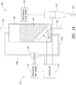
- Figure 1A is a schematic side view of a portion of an abrasive jet system 100 ("system 100").
- the system 100 includes a nozzle assembly or cutting head 115 that is operably coupled to each of a controller 120 and a pressurized fluid source 160 (e.g., a high-pressure fluid pump).
- the fluid source 160 is configured to supply a pressurized fluid, such as water or other suitable working liquids, to the cutting head 115.
- the system 100 also includes an abrasive container 105 that is coupled to the cutting head 115 via an abrasive supply conduit 145.
- the abrasive container 105 contains abrasives 150 that are combined with the working fluid at the cutting head 115 to form an abrasive fluid jet 103.
- the abrasives 150 can include garnet, aluminum oxide, baking soda, sugars, salts, ice particles, or other suitable jet cutting abrasives.
- the abrasive container 105 is coupled to the abrasive supply conduit 145 via an abrasive valve assembly 140 that can selectively open to allow the abrasives 150 to flow to the cutting head 115 through the abrasive supply conduit 145.
- the system 100 can also include an abrasive inlet connector or conduit 124 (shown in broken lines) that can be coupled to the abrasive container 105 to facilitate adding or feeding abrasives 150 to the abrasive container 105 from a bulk feeding device.
- the abrasive inlet conduit 124 can be sealed or otherwise closed off with reference to the abrasive container 105 (e.g., via a valve or other suitable device) to prevent a pressure drop in the abrasive container 105 during operation.
- the system 100 further includes a pressurized gas system 101.
- the pressurized gas system 101 includes a pressurized gas source 110 (e.g., a compressor) that is operably coupled to the controller 120.
- the pressurized gas source 110 is configured to supply a pressurized gas, such as air or other suitable working gases, to the cutting head 115 and/or to the abrasive container 105.
- a valve 130 operably couples the pressurized gas source 110 to corresponding pressurized gas supply conduits 125 (identified individually as a first gas supply conduit 125a and a second gas supply conduit 125b).
- the first gas supply conduit 125a couples the pressurized gas source 110 to the cutting head 115 via the abrasive supply conduit 145.
- the second gas supply conduit 125b couples the pressurized gas source 110 to the abrasive supply container 105.
- the pressurized gas system 101 selectively supplies pressurized gas to the cutting head 115 to affect or alter the abrasive fluid jet emitted by the cutting head 115.
- the controller 120 is operably coupled to several of the illustrated components of the system 100 via electrical wiring shown schematically in Figure 1A , wireless connections, or other suitable connections.
- the controller 120 can also be operably coupled to other components of the abrasive jet system such as the high-pressure fluid source 160, as well as other components of the abrasive jet system not shown in Figure 1A .
- the controller can be operably coupled to a bridge that is movable along a table of the abrasive jet system and along which the cutting head 115 is movable, and other components as is known in the art.
- the controller 120 includes control software, firmware, and/or hardware for controlling components of the abrasive jet system 100.
- the controller 120 can include a computer having a processor, memory (e.g., ROM, RAM) storage media (e.g., hard drive, flash drive, etc.) user input devices (e.g., keyboard, mouse, touch-screen, etc.), output devices (e.g., displays), input/output devices (e.g., network card, serial bus, etc.), an operating system (e.g., a Microsoft Windows operating system), and application programs and data.
- the controller 120 can include layout software for generating and/or importing Computer-Aided Design (CAD) drawings or other suitable drawings or information from which cutting or piercing operations can be derived.
- CAD Computer-Aided Design
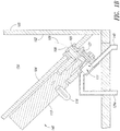
- Figure 1B is an enlarged schematic side view of a portion of the system 100 of Figure 1A .
- the abrasive the abrasive container 105 includes a first or bottom wall 104 angled obliquely with respect to a second or sidewall 102.
- the bottom wall 104 has an opening 105 that is coupled to the abrasive valve 140.
- the abrasive valve 140 at least partially defines a passage 108 through which the abrasives 150 can exit the abrasive container 105. More specifically, the abrasives 150 flow from the abrasive container 105 through the passage 108 to a collector portion 111 of the abrasive supply conduit 145, as shown by a broken arrow 109.
- the abrasive valve 140 includes an actuator 116 (e.g., a solenoid, gear motor, etc.) operably coupled to the controller 120 ( Figure 1A ) and a gas cylinder 113.
- the abrasive valve 140 can further include a tapered plug or end portion 121 that is movable relative to the passage 108.
- the actuator 116 moves the end portion 121 to an open position, a closed position, or to an intermediate position to meter a flow of abrasives 150 through the passage 108 and into the abrasive supply conduit 145.
- the end portion 121 is shown in the closed position to block or prevent the flow of abrasives 150 into the collecting portion 111 of the abrasive supply conduit 145.
- the system 100 can include other devices for metering or dispensing the abrasives 150 from the abrasive container 150.
- the system 100 can include one or more metering devices such as vibrators feeders, augers, drum feeders, variable sized orifices, and/or other suitable abrasive feeding devices.
- the controller 120 transmits control signals to each of the pressurized fluid source 160 and the abrasive valve 140 to form the abrasive jet 103 for processing (e.g., piercing, cutting, engraving, marking, etc.).
- the controller can further transmit control signals to the pressurized gas source 110 and/or the valve 130 to convey the pressurized gas to the cutting head 115 via the first pressurized gas supply conduit 125a and the abrasive delivery conduit 145.
- the controller 115 can also transmit signals to direct the valve 130 to dispense pressurized gas to the abrasive container 105 via the second pressurized gas supply conduit 125b.
- the system 100 can maintain an at least generally zero net pressure differential across the passage 108 of the abrasive valve 140.
- the pressure upstream from the abrasive valve 140 (e.g., in the abrasive container 105) can be controlled to be equivalent, or at least generally equivalent to the pressure downstream from the abrasive valve 140 (e.g., in the abrasive delivery conduit 145) so that there is not a pressure drop across the abrasive valve 140.
- the system 100 can also maintain a generally constant flow of the abrasives 150 exiting the abrasive container 105 during a transition when the system 100 activates or deactivates the pressurized gas source 110.
- the system 100 can maintain a generally constant flow of abrasive 150 in the abrasive jet 103 with little to no interruption when the controller 120 activates or deactivates the pressurized gas source 110.
- the system 100 activates the pressurized gas source 110 to add pressurized gas to the abrasive jet 103 for a startup or piercing the target material.
- the system 100 can deactivate the pressurized gas source 110 to remove or eliminate the pressurized gas from the abrasive jet 103. Further details regarding the effect of the pressurized gas on the abrasive jet are described below with reference to Figures 1C and 1D .
- the system 100 can maintain a pressure differential across the abrasive valve 140.
- the pressurized gas valve 130 can increase the pressure upstream from the abrasive valve 140 (e.g., in the abrasive container 105) relative to the pressure downstream from the abrasive valve 140 (e.g., in the abrasive delivery conduit 145) to maintain, increase, or otherwise alter the flow of abrasives 150 from the abrasive container 105.
- Figures 1C and 1D illustrate the apparent effect that the pressurized gas can have on the abrasive jet 103 in one embodiment. More specifically, Figure 1C is a cross-sectional side partial view of the cutting head 115 of Figure 1A during operation without the addition of the pressurized gas to the cutting head 115.
- the cutting head 115 includes a mixing tube 170 that is fluidly coupled to the abrasive supply conduit 145.
- the mixing tube 171 includes an axial passage that is generally aligned with a fluid orifice 167 in the cutting head 115.
- a pressurized fluid stream or jet 166 enters the cutting head 115 via the fluid orifice 167, and abrasives 150 enter the cutting head 115 via the abrasive supply conduit 145 because of the Venturi effect.
- the abrasives 150 combine with the fluid jet 166 at a mixing region 168 of the cutting head 115.
- the combined abrasives 150 and fluid jet 166 pass through the axial passage 171 and exit the mixing tube 170 as a first abrasive jet 103a.
- pressurized gas from the pressurized gas source 110 ( Figure 1A ) has not been supplied to the cutting head 115 or the first abrasive jet 103a.
- the first abrasive jet 103a illustrated in Figure 1C has a generally uniform, constant, and/or consistent stream or appearance.
- the first abrasive jet 103a has a first cross-sectional dimension or diameter D 1 that is generally constant extending from the mixing tube 170 to the surface of the target material.
- Figure 1D is also a cross-sectional side partial view of the cutting head 115.
- pressurized gas 172 enters the cutting head 115 along with the abrasives 150 via the abrasive supply conduit 145.
- the pressurized gas 172 and abrasives 150 combine with the pressurized fluid stream 166 at the mixing region 168.
- the combined pressurized gas 172, abrasives 150, and fluid jet 166 exit the mixing tube 170 as a second type of abrasive jet 103b.
- the second abrasive jet 103b illustrated in Figure 1D can have a slightly irregular or mildly dispersed or mildly diffused appearance.
- the second abrasive jet 103b can have a second cross-sectional dimension D 2 that is slightly irregular or slightly diffused at various positions extending along the second abrasive jet 103b from the mixing tube 170 to the surface of the target material.
- first and second abrasive jets 103a, 103b shown in Figures 1C and 1D may have exaggerated sizes and/or features for purposes of illustration to show the apparent effect of the presence or absence of the pressurized gas 172 on the abrasive jet streams exiting the mixing tube 170 in some embodiments.
- a first mode of operation can be without the pressurized gas added to the first abrasive stream 103a as shown in Figure 1C .
- At least a second mode can include pressurized gas 172 that is added to the second abrasive jet 103b as shown in Figure 1D .
- the first and second operational modes can include approximately the same amount of abrasive 150 entrained in the corresponding abrasive jets 103a, 103b.
- the abrasive flow rate, as well as the fluid flow rate can remain approximately equal in the first and second operational modes. In other embodiments, however, these flow rates can differ with the first and second operational modes.
- piercing and cutting operations can each be accomplished with the pressurized gas flow added to the abrasive jet.
- the addition of the pressurized gas in the second abrasive jet 103b is configured to alter the abrasive stream in such a way that piercing damage to the target material is reduced or eliminated.
- Adding the pressurized gas to the abrasive jet 130b can further entrain or collect more abrasives 150 for the abrasive jet 103b than would typically be added to the abrasive jet 103b via the Venturi effect alone resulting from the pressurized fluid.
- the pressurized gas can collect and/or direct the abrasives 150 to the cutting head 115.
- the addition of the pressurized gas into the cutting head 115 can also supply the abrasives 150 for the abrasive jet 103b at a fluid pressure of the jet stream 166 that is lower than a fluid pressure of the jet stream 166 that would typically be required to entrain the abrasives 150 due to the Venturi effect alone.
- the pressurized gas can be selectively or intermittently increased to clear a blockage in the system.
- the pressurized gas can transport the abrasives 150 to the mixing region 168 in the cutting head 115 before the jet stream 166 is initiates so that when the jet stream 166 is activated the abrasive jet 130 is immediately formed due to the presence of the abrasives 150 in the mixing region 168.
- abrasive jets or waterjets are their tendency to induce damage during piercing delicate materials. Certain materials, such as composites, laminates, and/or brittle materials may be difficult to pierce with an abrasive jet. Embodiments of the present disclosure, however, are able to mitigate or eliminate piercing damage to the target material. For example, although the presence of the pressurized gas 172 in the second mode of operation may degrade or otherwise diminish the quality of the second abrasive jet 103b, the inventors have found that the second abrasive jet 103b is particularly suited for piercing.
- the second abrasive jet 103b or second operational mode particularly suited for mitigating piercing damage with delicate materials, such as composite, laminate, and/or brittle materials.
- the first abrasive jet 103a or first operational mode particularly suited for continuing to cut or otherwise removing material following an initial piercing operation.
- Low pressure piercing may involve piercing the material with an abrasive jet at a lower fluid pressure than would typically be used for cutting.
- Pressure ramping can involve using a reduced water pressure to form the waterjet in an attempt to ensure that abrasives are fully entrained in the waterjet before a hydrostatic pressure induced by fluid water alone reaches a magnitude capable of causing damage to the material being pierced.
- a vacuum assist device can also be used to draw abrasive into a mixing chamber of a waterjet cutting head prior to the arrival of water into the mixing chamber.
- piercing damage mitigation techniques include superheating high pressure water downstream of the pump and upstream of the nozzle such that the pressurized high-temperature water remains in the liquid state upstream of the inlet orifice in the nozzle and then evaporates upon exiting the nozzle, as disclosed in U.S. Patent No. 7,815,490 , which is incorporated herein by reference in its entirety.
- U.S. Patent No. 7,815,490 which is incorporated herein by reference in its entirety.
- Yet another piercing damage mitigation technique involves pressurized abrasive feeding to degrade the abrasive jet in a controlled manner, as disclosed in U.S. Provisional Patent Application No. 61/390,946 , entitled "SYSTEMS AND METHODS FOR ALTERING AN ABRASIVE JET FOR PIERCING OF DELICATE MATERIALS,” filed October 7, 2010, and incorporated by reference herein in its entirety.
- the alteration of the abrasive jet via pressurized abrasives is believed to reduce the magnitude of the hydrostatic pressure inside a cavity while the pressurized abrasive feeding would ensure an abrasive waterjet is formed before reaching the workpiece ensuring a fluid alone does not reach the material before abrasives are mixed with the fluid.
- Figures 2A-4 illustrate various abrasive jet systems configured in accordance with embodiments of the disclosure.
- the systems illustrated in Figures 2A-4 include several features that are generally similar in structure and function to the corresponding features of the system 100 described above with reference to Figures 1A-1D .
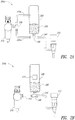
- Figure 2A is a side view of an abrasive jet system 200a ("system 200a") including a pressurized gas source 210 that is coupled to an abrasive container 205 and a cutting head 215.
- a gas valve, regulator, or connector 230 couples the pressurized gas source 210 to each of a first pressurized gas supply conduit 225a and a second pressurized gas supply conduit 225b.
- the first pressurized gas supply conduit 225a couples the gas source 210 to the abrasive container 205 via an abrasive connector 240.
- the second pressurized gas supply conduit 225b couples the gas source 210 directly to the abrasive container 205 upstream from the abrasive connector 240.
- an abrasive supply conduit 245 couples the abrasive connector 240 to the cutting head 215 to deliver abrasives 250 to the cutting head 215.
- a pressurized fluid source (not shown) can also be coupled to the cutting head 215 to combine a pressurized fluid with the abrasives 250 to form the abrasive jet that is emitted from the cutting head 215.
- the system 200a can further include a controller (not shown) that is operably coupled to one or more of the operable components of the system 200a.
- the abrasive connector 240 can be a relatively simple or uncomplicated mechanical connector, such as a tee fitting or a tee coupling. As such, the abrasive connector 240 forms a junction between the first pressurized gas supply conduit 225a, the abrasive container 205, and the abrasive supply conduit 245. The abrasive connector 240 can therefore deliver the abrasives 250 to the abrasive supply conduit 245 without any moving parts or complicated on/off functionality. Moreover, in certain embodiments, the gas connector 230 can be generally similar in structure and function to the abrasive connector 240.
- the system 200a can operate in a manner generally similar to the operation of the system 100 described above with reference to Figures 1A-1D .
- the cutting head 215 can emit an abrasive jet including abrasives 250 combined with a pressurized fluid.
- the pressurized gas source 210 can supply a pressurized gas to the cutting head 215 via the first pressurized gas supply conduit 225a and the abrasive supply conduit 245.
- the pressurized gas source 210 can also supply the pressurized gas to the abrasive container 205 via the second pressurized gas supply conduit 225b.
- FIG 2B is a side partially schematic view of an abrasive jet system 200b (“system 200b") configured in accordance with another embodiment of the disclosure.
- the abrasive system 200b includes the same features as the system 200a described above with reference to Figure 2A , with the exception that the pressurized gas source 210 is not coupled to the abrasive container 250 upstream from the abrasive connector 240. More specifically, only a single pressurized gas supply conduit 225 is coupled to the pressurized gas source 210. The pressurized gas supply conduit 225 is further coupled to the abrasive connector 240. The abrasive connector 240 is further coupled to the abrasive container 205 to deliver the abrasives 250 to the cutting head 215.
- the system 200b can include an abrasive flow assister 273 (shown schematically).
- the abrasive flow assister 273 is configured to assist or facilitate the flow of the abrasives 250 from the abrasive container 205 to the abrasive connector 240 and the abrasive supply conduit 245.
- the abrasive flow assister 273 can be an agitator, vibrator, auger, fluidizer, or other suitable device for assisting or otherwise flowing the abrasives out of the abrasive container 205.
- the system 200b can function solely as a gravity abrasive feed system without the abrasive flow assister 273.
- the pressurized gas source 210 can supply pressurized gas to the cutting head 215 to combine with the abrasive jet for certain processing operations, such as for piercing for example.
- FIG 2C is a side partially schematic view of an abrasive jet system 200c (“system 200c") configured in accordance with another embodiment of the disclosure.
- the abrasive system 200c includes the same features as the system 200a described above with reference to Figure 2A , with the exception that the pressurized gas source 210 is coupled to the first pressurized gas conduit 225a via a first valve or regulator 230a, and to the second pressurized gas conduit 225b via a second valve or regulator 230b.
- the first and second valves 230 can be operably coupled to a corresponding controller. As such, the first and second valves 230 can be independently controlled to direct or otherwise control the flow of the pressurized gas to each of the abrasive container 205 and the cutting head 215.
- FIG 3A is a side view of an abrasive jet system 300 (“system 300") configured in accordance with an additional embodiment of the disclosure.
- the system 300 includes a cutting head 315 that is coupled to a pressurized gas source 310 and an abrasive supply container (not shown).
- the system 300 further includes a nozzle 374 that directs pressurized gas to combine with abrasives. More specifically, a pressurized gas supply conduit 325 couples the pressurized gas source 310 to the nozzle 374.
- a first abrasive supply conduit 345a couples the abrasive container to the nozzle 374.
- a second abrasive supply conduit 345b couples the nozzle 374 to the cutting head.
- Figure 3B is an enlarged view of a portion of the system 300 of Figure 3A illustrating the connection of the nozzle 374 to each of the pressurized gas supply conduit 325 and the first and second abrasive supply conduits 345a, 345b.
- the nozzle 374 directs pressurized gas 376 from the pressurized gas supply conduit 325 to combine with abrasives form the first abrasive supply conduit 345a to flow through the second abrasive supply conduit 345b.
- the nozzle 374 can be an eductor, jet pump, or other suitable device for combining the 350 and pressurized gas 376 with the abrasives 350 downstream and/or spaced apart from the abrasive container 305.
- the nozzle 374 includes a converging portion 378, a jet or needle valve 375, and a diverging portion 379.
- the nozzle 374 can utilize the Venturi effect to create a low pressure zone in the gas 376 that draws in and entrains the abrasives into the gas flow 376.
- the combined abrasives and gas 377 can then be delivered to the cutting head ( Figure 3A ) via the second abrasive supply conduit 345b.
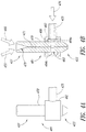
- Figure 4A is a side view and Figure 4B is a cross-sectional side view of a mixing tube subassembly 481 ("subassembly 481").
- the subassembly 481 includes a mixing tube 470 having several features that are generally similar in structure and function to the mixing tube 170 described above with reference to Figures 1C and 1D .
- the mixing tube 470 illustrated in Figures 4A and 4B includes an axial passage 471 extending longitudinally therethrough from a proximal end portion 431 to a distal end portion 433 of the mixing tube 470.
- the mixing tube 470 further includes an inlet region 479 at the proximal end portion 431 that is configured to receive abrasives 450 and pressurized fluid 466 to form an abrasive jet that exits the proximal end portion 433 of the mixing tube 470.
- the subassembly also includes a gas conduit coupling 482 that is configured to couple the mixing tube 470 to a pressurized gas supply conduit 425.
- the distal end portion 433 of the mixing tube 470 includes a latitudinal passage 483 extending from a first opening 484a to a second opening 484b.
- the latitudinal passage 483 extends in a direction that is generally transverse to the longitudinal axis of the mixing tube 470.
- the latitudinal passage 483 further includes a jet stream recess 485 in a central portion of the latitudinal passage 483 that is generally aligned with the axial passage 471.
- the gas conduit coupling 482 couples directly to the gas supply conduit 428
- gas conduit coupling 482 fluidly connects the gas supply conduit 425 to the distal end portion 433 of the mixing tube 470 at a location that is generally aligned with the latitudinal passage 483.
- abrasives 450 and pressurized fluid 466 enter the proximal end portion 431 of the mixing tube 470 to form an abrasive jet.
- Pressurized gas 476 can enter the distal end portion 433 of the mixing tube 470 via the gas supply conduit 425 and gas conduit coupling 482 during certain operational modes, such as during piercing.
- the pressurized gas can enter the distal end portion 433 of the mixing tube 470 via the latitudinal passage 483 and mix or otherwise combine with the abrasive jet at the jet stream recess 485.
- the pressurized gas 476 enters the mixing tube 433 at a location that is downstream from and also separate from the location where abrasives 450 enter the mixing tube 470.
- the pressurized gas 476 can be added to the fluid jet 466 independently from the abrasives 450.
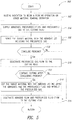
- FIG. 5 is a flow diagram of a method or process 500 configured in accordance with embodiments of the present disclosure for piercing and cutting operations using abrasive jet systems as disclosed herein.
- the process 500 includes receiving an indication to begin a piercing operation or other material removal operation with an abrasive jet system (block 502).
- the indication to begin the piercing operation can be received from an operator of the abrasive jet system, control software of the controller, or from any other suitable source.
- the process 500 further includes supplying abrasives from an abrasive supply, pressurized fluid from a pressurized fluid supply, and pressurized gas from a pressurized gas supply to the cutting head of the abrasive jet system (block 504).
- the abrasives, pressurized fluid, and pressurized gas are supplied to the cutting head to arrive at the target material at the same time.
- the order of the flow of abrasives, pressurized fluid, and pressurized gas to the cutting head can vary.
- the pressurized gas can be supplied to the cutting head after the abrasives and pressurized fluid are supplied to the cutting head.
- the abrasives, pressurized fluid, and pressurized gas can be supplied in any suitable order for combining these constituents to form the abrasive jet that is configured for piercing.
- the order of the abrasives, pressurized fluid, and pressurized gas can be controlled to ensure that the pressurized fluid alone does not reach the target material (e.g., without the abrasives or the pressurized gas).
- the abrasives and pressurized fluid may be combined and/or directed to the target material prior to the addition of the pressurized fluid to the abrasive jet.
- the abrasives and pressurized gas can at least partially combine upstream from the cutting head and be supplied to the cutting head via the same supply conduit.
- the pressurized gas can be supplied to the cutting head separately from the abrasives and the pressurized fluid. More specifically, in one embodiment the pressurized gas can be supplied to the cutting head downstream from the ingress of the abrasives and/or pressurized gas into the cutting head. In other embodiments, however, the pressurized gas can enter the cutting head upstream from the ingress of the abrasives and/or pressurized fluid into the cutting head.
- pressurized gas can also be supplied to the abrasive container (in addition to the cutting head) at a location that is upstream from an abrasive outlet of the abrasive container.
- the pressurized gas source can maintain a generally net zero pressure differential or otherwise prevent a pressure drop across the abrasive container.
- the pressurized gas source can provide gas at various pressures, such as from approximately 5 PSI or less to approximately 120 PSI or more.
- the gas pressure can depend upon various factors, such as the type or thickness of the target material, an inside diameter of a passage of the mixing tube of the cutting head, size of the pierced hole, abrasive jet kerf, etc.
- the controller may provide gas at a relatively lower pressure (e.g., from approximately 10 PSI to approximately 50 PSI) for mixing tubes with relatively smaller inside diameters, and gas at a relatively higher pressure (e.g., from approximately 40 PSI to approximately 100 PSI) for mixing tubes with relatively larger inside diameters.
- the introduction of pressurized gas into the waterjet does not cause or otherwise result in a phase change (e.g., from liquid to gas) of the fluid in the abrasive jet.
- the pressure of the fluid provided by the pressurized fluid, the abrasive flow rate provided by the abrasive source, and/or the pressure of the gas provided by the pressurized gas source can vary based on various factors. These factors can include, for instance, the type or thickness of the target material, a kerf size of the abrasive jet, an inside dimension of a passage of a mixing tube of the cutting head, required piercing and cutting speed or quality, as well as other factors.
- a relatively low fluid pressure e.g., from approximately 3,000 PSI or less to approximately 5,000 PSI or more
- a higher fluid pressure e.g., from approximately 10,000 PSI to approximately 50,000 PSI or more
- the abrasive jet system can also vary the fluid delivery pressure, gas delivery pressure, abrasive delivery flow rate, as well as the rate at which these constituents change based on these and other factors.
- the process 500 can further include controlling an external bulk hopper to maintain an abrasive supply for the system.
- the addition of the pressurized gas to the abrasive jet can allow for piercing operations at fluid pressures that are lower than typical piercing fluid pressures for abrasive jets.
- the fluid pressure in piercing operations may typically be approximately 40,000 PSI or greater, and for low pressure piercing operations it may typically be 20,000 PSI or greater.
- the fluid pressure can be reduced even further.
- the fluid pressure can be reduced from approximately 1,000 PSI to approximately 10,000 PSI or from approximately 2,000 PSI to approximately 5,000 PSI.
- the addition of the pressurized fluid can provide supply the suitable amount of abrasives to the abrasive jet for piercing.
- the process 500 further includes piercing the target material with the abrasive jet (block 506).
- Piercing the target material, and in particular piercing target materials that are brittle or delicate includes adding the pressurized gas to the abrasive jet.
- the addition of the pressurized gas to the abrasive jet can mildly disperse or diffuse the abrasive jet as generally described above with reference to Figures 1D , while still supplying a constant flow rate of abrasives and fluid in the abrasive jet. In other embodiments, however, the flow rate of the abrasives and/or fluid can vary.
- the method 508 further includes determining when to conclude the piercing operation (decision block 508).
- the process 500 includes deactivating the pressurized gas flow to the cutting head (block 510), and determining if further cutting or other material removal is required (decision block 512). If further cutting is desired, the process 500 includes cutting the target material with the abrasive jet including abrasive and pressurized fluid and without the pressurized gas (block 514). Cutting with the pressurized gas removed from the abrasive jet produces a generally uniform abrasive jet as described above with reference to Figure 1C .
- the abrasive jet system can begin cutting at the location of the hole that was initially pierced through the workpiece. Additionally or alternatively, the abrasive jet system can repeat the steps at blocks 506 and/or 514 one or more times to pierce and/or cut the workpiece one or more times (e.g., to make multiple holes or cuts in the workpiece).
- the abrasive jet system can vary sequences of piercing and cutting operations.
- the process 500 further includes deactivating the abrasive flow and the pressurized fluid flow to the cutting head (block 516). If further cutting is not desired following decision block 512, the process 500 can also proceed to block 516.
- the controller can receive an indication from a component that detects the completion of the piercing and/or cutting operations. In other embodiments, the controller can cause the piercing and/or cutting operations to conclude after a predetermined period of time that is based upon various factors such as the thickness of the workpiece, a dwell time, the pressure of the gas flowing through the cutting head, the abrasive flow rate, as well as other suitable factors.
- the process 500 can conclude.
- steps shown in Figure 5 may be altered in a variety of ways without departing from the spirit or scope of the present disclosure. For example, the order of the steps may be rearranged, sub-steps may be performed in parallel, illustrated steps may be omitted, additional steps may be included, etc.
- the systems described herein include a pressurized gas source
- the pressurized gas source can include other suitable sources of gases or fluids that are mixed with abrasives and delivered to a cutting head or delivered directly to the cutting head.
- the pressurized gas sources described herein can include two or more separate pressurized gas sources, each independently controllable by a controller.
- each of the first and second pressurized gas supply conduits can be operably coupleable to corresponding separate pressurized gas sources.
- the first and second pressurized gas supply conduits can each include corresponding flow control valves that are independently controllable by a controller.
- the use of two or more separate and independent pressurized gas sources can enable the use of different gas pressures in the corresponding pressurized gas supply conduits. This can allow the pressurized gas sources to, among other things, provide a pressure in the abrasive container that is different from the pressure in the abrasive supply conduit.
- the controller can include a computer
- the controller can include an integrated circuit, a microcontroller, an application-specific integrated circuit, or any device or apparatus suitable for controlling the abrasive jet system and/or the gas pressurization system.
- instructions for controlling the abrasive jet system and the pressurized gas sources as disclosed herein have been described as being implemented in software, such instructions can be implemented in software, hardware, firmware, or any combination thereof.
- an abrasive jet system can include a first cutting head for cutting operations and a separate second cutting or piercing head for piercing operations.
- the abrasive jet system could also include a switch to switch delivery of high-pressure fluid between the two cutting heads.
- the pressurized gas source can also be operably coupled to each of the cutting and piercing heads. The distance between the cutting head (for cutting operations) and the piercing head (for piercing operations) would be known to the controller. The controller could cause piercing cutting head to pierce a hole in a workpiece.
- the controller could cause the cutting head to move so that cutting head is positioned over the pierced hole. The controller could then cause the cutting head to begin a cutting operation starting from the pierced hole. The controller could cause either the abrasive jet system to perform piercing operations prior to performing cutting operations, or cause the abrasive jet system to intersperse cutting operations with piercing operations.
- One advantage to an abrasive jet system having separate cutting and piercing heads is that the pressurized gas source could remain activated while no piercing operations are being performed, thereby obviating a need to cycle the pressurized gas source on and off. Instead, the controller could close the abrasive valve to prevent abrasives from being conveyed to the cutting head.
- the components of the abrasive jet systems described above can be positioned in relatively close proximity to one another.
- the components described above can be located within approximately 5 feet or less from one another.
- all of these components can be located on the same table or bridge upon which the cutting head is positioned. In other embodiments, however, these components can be positioned at locations that are spaced more than 5 feet apart from each other.
Landscapes
- Engineering & Computer Science (AREA)
- Mechanical Engineering (AREA)
- Perforating, Stamping-Out Or Severing By Means Other Than Cutting (AREA)
- Nozzles (AREA)
Claims (11)
- Abrasivstrahlsystem (100), das dazu konfiguriert ist, zumindest einen Teil eines Zielmaterials mit einem Abrasivstrahl (103) zu entfernen, wobei das Abrasivstrahlsystem umfasst:einen Schneidkopf (115), der dazu konfiguriert ist, den Abrasivstrahl zu bilden;eine Flüssigkeitsquelle (160), die mit dem Schneidkopf verbunden und dazu konfiguriert ist, unter Druck stehende Flüssigkeit zu dem Schneidkopf zu leiten;einen Strahlmittelbehälter (105), der mit dem Schneidkopf verbunden und dazu konfiguriert ist, Strahlmittel (150) zu dem Schneidkopf zu leiten, wobei der Schneidkopf dazu konfiguriert ist, die Strahlmittel mit der unter Druck stehenden Flüssigkeit zu kombinieren, um den Abrasivstrahl zu bilden;eine Gasquelle (110), die mit dem Schneidkopf verbunden und dazu konfiguriert ist, selektiv unter Druck stehendes Gas zu dem Schneidkopf zu leiten, wobei, wenn die Quelle für unter Druck stehendes Gas das unter Druck stehende Gas zu dem Schneidkopf leitet, der Schneidkopf das unter Druck stehende Gas, die Strahlmittel und die unter Druck stehende Flüssigkeit kombiniert, um den Abrasivstrahl zu bilden;eine Strahlmittelzufuhrleitung (145), die den Strahlmittelbehälter mit dem Schneidkopf verbindet; undeine Gaszufuhrleitung (125a), welche die Gasquelle mit der Strahlmittelzufuhrleitung verbindet, wobei die Gasquelle das unter Druck stehende Gas zu dem Schneidkopf über die Gaszufuhrleitung und die Strahlmittelzufuhrleitung leitet.
- Abrasivstrahlsystem nach Anspruch 1, wobei:wenn der Abrasivstrahl das unter Druck stehende Gas nicht enthält, der Abrasivstrahl eine erste Querschnittsabmessung (D1) aufweist; undwenn der Abrasivstrahl das unter Druck stehende Gas enthält, der Abrasivstrahl eine zweite Querschnittsabmessung (D2) aufweist, die sich von der ersten Querschnittsabmessung unterscheidet.
- Abrasivstrahlsystem nach Anspruch 2, wobei die zweite Querschnittsabmessung im Allgemeinen unregelmäßiger als die erste Querschnittsabmessung ist, die sich von dem Schneidkopf zu dem Zielmaterial erstreckt.
- Abrasivstrahlsystem nach Anspruch 1, wobei:der Strahlmittelbehälter einen Strahlmittelauslass aufweist;die Gaszufuhrleitung eine erste Gaszufuhrleitung ist, die mit der Strahlmittelzufuhrleitung an einer Position stromabwärts von dem Strahlmittelauslass verbunden ist; unddas Abrasivstrahlsystem des Weiteren eine zweite Gasversorgungsleitung (125b) umfasst, welche die Gasquelle mit dem Strahlmittelbehälter an einer Position stromaufwärts von dem Strahlmittelauslass verbindet.
- Abrasivstrahlsystem nach Anspruch 4, wobei die Gasquelle dazu konfiguriert ist, im Allgemeinen gleiche Gasdrücke stromaufwärts und stromabwärts von dem Strahlmittelauslass aufrecht zu erhalten, wenn die Gasquelle das unter Druck stehende Gas zu dem Schneidkopf leitet.
- Verfahren zum Betreiben eines Abrasivstrahlsystems (100), wobei das Verfahren umfasst:funktionsmäßiges Verbinden einer Steuerung (120) mit einem Strahlmittelbehälter (105), einer Quelle (160) für unter Druck stehende Flüssigkeit, einem Schneidkopf (115) und einer Quelle (110) für unter Druck stehendes Gas;Senden von einem oder mehreren Signalen von der Steuerung zu dem Strahlmittelbehälter, um Strahlmittel zu dem Schneidkopf zu leiten;Senden von einem oder mehreren Signalen von der Steuerung zu der Quelle für unter Druck stehende Flüssigkeit, um Flüssigkeit zu dem Schneidkopf zu leiten und mit Strahlmitteln zu kombinieren und einen Abrasivstrahl zu bilden, der von dem Schneidkopf emittiert wird; undSenden von einem oder mehreren Signalen von der Steuerung zu der Quelle für unter Druck stehendes Gas, um einen Druck in zumindest einem Teil des Schneidkopfes zu erhöhen, wobei der erhöhte Druck zumindest teilweise den Abrasivstrahl zerstreut;wobei das Abrasivstrahlsystem des Weiteren eine Strahlmittelzufuhrleitung (145) umfasst, die den Strahlmittelbehälter mit dem Schneidkopf verbindet, und eine Gaszufuhrleitung (125a), welche die Quelle für unter Druck stehendes Gas mit der Strahlmittelzufuhrleitung verbindet;wobei das Senden von einem oder mehreren Signalen von der Steuerung zu dem Strahlmittelbehälter das Senden von einem oder mehreren Signalen von der Steuerung zu dem Strahlmittelbehälter umfasst, um die Strahlmittel über die Strahlmittelzufuhrleitung zu dem Schneidkopf zu leiten; undwobei das Senden von einem oder mehreren Signalen von der Steuerung zu der Quelle für unter Druck stehendes Gas das Senden von einem oder mehreren Signalen von der Steuerung zu der Quelle für unter Druck stehendes Gas umfasst, um unter Druck stehendes Gas durch zumindest einen Teil der Strahlmittelzufuhrleitung zu dem Schneidkopf zu leiten.
- Verfahren nach Anspruch 6, wobei das Senden von einem oder mehreren Signalen von der Steuerung zu der Quelle für unter Druck stehendes Gas das Erhöhen des Drucks in zumindest einem Teil des Schneidkopfes umfasst, um ein Zielmaterial mit dem Abrasivstrahl zu durchbohren.
- Verfahren nach Anspruch 6 oder7, des Weiteren umfassend das Senden von einem oder mehreren Signalen von der Steuerung zu der Quelle für unter Druck stehendes Gas, während der Druck in dem Schneidkopf erhöht wird, um den Druck in dem Schneidkopf zum Schneiden des Zielmaterials mit dem Abrasivstrahl zu verringern.
- Verfahren nach einem der Ansprüche 6 bis 8, wobei nach dem Erhöhen des Drucks in dem Schneidkopf das Verfahren des Weiteren das Senden von einem oder mehreren Signalen von der Steuerung zu der Quelle für unter Druck stehendes Gas umfasst, um den Druck in zumindest einem Teil des Schneidkopfes zu reduzieren, wobei der reduzierte Druck den Abrasivstrahl so beeinflusst, dass er eine im Allgemeinen gleichförmige Querschnittsabmessung aufweist.
- Verfahren nach Anspruch 6, wobei:die Gaszufuhrleitung eine erste Gaszufuhrleitung ist und das Abrasivstrahlsystem des Weiteren eine zweite Gaszufuhrleitung umfasst, welche die Quelle für unter Druck stehendes Gas mit dem Strahlmittelbehälter verbindet; unddas Verfahren des Weiteren das Senden von einem oder mehreren Signalen von der Steuerung zu der Quelle für unter Druck stehendes Gas umfasst, um einen Druck in dem Strahlmittelbehälter über die zweite Gaszufuhrleitung zu erhöhen.
- Verfahren nach Anspruch 6 oder 10, wobei:der Strahlmittelbehälter ein Strahlmittelventil beinhaltet, das mit der Strahlmittelzufuhrleitung und der Gaszufuhrleitung verbunden ist, wobei das Strahlmittelventil funktionsmäßig durch die Steuerung steuerbar ist; unddas Verfahren des Weiteren das Senden von einem oder mehreren Signalen von der Steuerung an das Strahlmittelventil umfasst, um das Strahlmittelventil zumindest zum Teil zu öffnen.
Applications Claiming Priority (1)
| Application Number | Priority Date | Filing Date | Title |
|---|---|---|---|
| US35706810P | 2010-06-21 | 2010-06-21 |
Publications (3)
| Publication Number | Publication Date |
|---|---|
| EP2397257A2 EP2397257A2 (de) | 2011-12-21 |
| EP2397257A3 EP2397257A3 (de) | 2015-03-25 |
| EP2397257B1 true EP2397257B1 (de) | 2018-01-03 |
Family
ID=44675955
Family Applications (1)
| Application Number | Title | Priority Date | Filing Date |
|---|---|---|---|
| EP11170744.4A Active EP2397257B1 (de) | 2010-06-21 | 2011-06-21 | Systeme zur Abrasionsstrahldurchbohrung und zugehörige Verfahren |
Country Status (3)
| Country | Link |
|---|---|
| US (2) | US9108297B2 (de) |
| EP (1) | EP2397257B1 (de) |
| AU (1) | AU2011203006B2 (de) |
Families Citing this family (49)
| Publication number | Priority date | Publication date | Assignee | Title |
|---|---|---|---|---|
| WO2011109482A1 (en) | 2010-03-04 | 2011-09-09 | Omax Corporation | Abrasive jet systems, including abrasive jet systems utilizing fluid repelling materials, and associated methods |
| EP2397257B1 (de) | 2010-06-21 | 2018-01-03 | Omax Corporation | Systeme zur Abrasionsstrahldurchbohrung und zugehörige Verfahren |
| US9782852B2 (en) | 2010-07-16 | 2017-10-10 | Hypertherm, Inc. | Plasma torch with LCD display with settings adjustment and fault diagnosis |
| US10455682B2 (en) | 2012-04-04 | 2019-10-22 | Hypertherm, Inc. | Optimization and control of material processing using a thermal processing torch |
| US9481050B2 (en) | 2013-07-24 | 2016-11-01 | Hypertherm, Inc. | Plasma arc cutting system and persona selection process |
| US10486260B2 (en) | 2012-04-04 | 2019-11-26 | Hypertherm, Inc. | Systems, methods, and devices for transmitting information to thermal processing systems |
| JP5205481B2 (ja) | 2011-02-02 | 2013-06-05 | 株式会社スギノマシン | アブレシブウォータージェット加工機 |
| US9616540B2 (en) * | 2011-02-08 | 2017-04-11 | The University Of Utah Research Foundation | System and method for dispensing a minimum quantity of cutting fluid |
| US9283656B2 (en) | 2011-04-01 | 2016-03-15 | Omax Corporation | Systems and methods for fluidizing an abrasive material |
| US9672460B2 (en) | 2012-04-04 | 2017-06-06 | Hypertherm, Inc. | Configuring signal devices in thermal processing systems |
| US11783138B2 (en) | 2012-04-04 | 2023-10-10 | Hypertherm, Inc. | Configuring signal devices in thermal processing systems |
| US9144882B2 (en) * | 2012-04-04 | 2015-09-29 | Hypertherm, Inc. | Identifying liquid jet cutting system components |
| US9395715B2 (en) | 2012-04-04 | 2016-07-19 | Hypertherm, Inc. | Identifying components in a material processing system |
| US9737954B2 (en) | 2012-04-04 | 2017-08-22 | Hypertherm, Inc. | Automatically sensing consumable components in thermal processing systems |
| US20150332071A1 (en) | 2012-04-04 | 2015-11-19 | Hypertherm, Inc. | Configuring Signal Devices in Thermal Processing Systems |
| US9586306B2 (en) * | 2012-08-13 | 2017-03-07 | Omax Corporation | Method and apparatus for monitoring particle laden pneumatic abrasive flow in an abrasive fluid jet cutting system |
| US8904912B2 (en) | 2012-08-16 | 2014-12-09 | Omax Corporation | Control valves for waterjet systems and related devices, systems, and methods |
| JP6000025B2 (ja) * | 2012-08-30 | 2016-09-28 | 株式会社不二製作所 | スクライブ加工方法及びスクライブ加工用のブラスト加工装置 |
| US9744645B2 (en) * | 2012-09-25 | 2017-08-29 | G.D.O. Inc. | Abrasive entrainment waterjet cutting |
| US9446500B2 (en) * | 2012-09-25 | 2016-09-20 | G.D.O. Inc. | Underwater abrasive entrainment waterjet cutting method |
| US9815175B2 (en) * | 2012-09-25 | 2017-11-14 | G.D.O. Inc | Abrasive entrainment waterjet cutting |
| US9090808B1 (en) | 2013-03-15 | 2015-07-28 | Omax Corporation | Abrasive materials for use in abrasive-jet systems and associated materials, apparatuses, systems, and methods |
| US9050704B1 (en) | 2013-03-15 | 2015-06-09 | Omax Corporation | Abrasive-delivery apparatuses for use with abrasive materials in abrasive-jet systems and related apparatuses, systems, and methods |
| CN104103161A (zh) * | 2013-04-02 | 2014-10-15 | 鸿富锦精密工业(深圳)有限公司 | 检测系统及方法 |
| US9643273B2 (en) | 2013-10-14 | 2017-05-09 | Hypertherm, Inc. | Systems and methods for configuring a cutting or welding delivery device |
| US9884406B2 (en) * | 2014-01-15 | 2018-02-06 | Flow International Corporation | High-pressure waterjet cutting head systems, components and related methods |
| US9658613B2 (en) | 2014-01-22 | 2017-05-23 | Omax Corporation | Generating optimized tool paths and machine commands for beam cutting tools |
| WO2015134966A1 (en) | 2014-03-07 | 2015-09-11 | Hypertherm, Inc. | Liquid pressurization pump and systems with data storage |
| US10786924B2 (en) | 2014-03-07 | 2020-09-29 | Hypertherm, Inc. | Waterjet cutting head temperature sensor |
| US20150269603A1 (en) | 2014-03-19 | 2015-09-24 | Hypertherm, Inc. | Methods for Developing Customer Loyalty Programs and Related Systems and Devices |
| CN106457514A (zh) * | 2014-04-29 | 2017-02-22 | 康宁股份有限公司 | 用于形成层压玻璃结构的研磨射流 |
| US9358667B2 (en) * | 2014-10-30 | 2016-06-07 | Shape Technologies Group, Inc. | System and method for low pressure piercing using a waterjet cutter |
| US9446501B2 (en) * | 2014-12-31 | 2016-09-20 | Spirit Aerosystems, Inc. | Method and apparatus for abrasive stream perforation |
| MX2017010478A (es) * | 2015-02-25 | 2017-11-28 | Sintokogio Ltd | Ensamble de boquilla y metodo de tratamiento de superficie con ensamble de boquilla. |
| US9638357B1 (en) | 2015-06-24 | 2017-05-02 | Omax Corporation | Mechanical processing of high aspect ratio metallic tubing and related technology |
| US10596717B2 (en) | 2015-07-13 | 2020-03-24 | Flow International Corporation | Methods of cutting fiber reinforced polymer composite workpieces with a pure waterjet |
| DE102015118610A1 (de) * | 2015-10-30 | 2017-05-04 | Nienstedt Gmbh | Vorrichtung zum Zerteilen von Lebensmitteln |
| US10434630B2 (en) * | 2016-05-18 | 2019-10-08 | Graco Minnesota Inc. | Vapor abrasive blasting system with closed loop flow control |
| US10077966B2 (en) * | 2016-08-15 | 2018-09-18 | G.D.O. Inc. | Abrasive entrainment waterjet cutting |
| US10076821B2 (en) * | 2016-08-15 | 2018-09-18 | G.D.O. Inc | Abrasive entrainment waterjet cutting |
| US11577366B2 (en) * | 2016-12-12 | 2023-02-14 | Omax Corporation | Recirculation of wet abrasive material in abrasive waterjet systems and related technology |
| US10859997B1 (en) | 2017-12-04 | 2020-12-08 | Omax Corporation | Numerically controlled machining |
| US11554461B1 (en) | 2018-02-13 | 2023-01-17 | Omax Corporation | Articulating apparatus of a waterjet system and related technology |
| US11224987B1 (en) | 2018-03-09 | 2022-01-18 | Omax Corporation | Abrasive-collecting container of a waterjet system and related technology |
| US12051316B2 (en) | 2019-12-18 | 2024-07-30 | Hypertherm, Inc. | Liquid jet cutting head sensor systems and methods |
| CN111890230B (zh) * | 2019-12-31 | 2022-01-04 | 南通仁隆科研仪器有限公司 | 一种物理除锈设备 |
| EP4127527A1 (de) | 2020-03-24 | 2023-02-08 | Hypertherm, Inc. | Hochdruckdichtung für ein flüssigkeitsstrahlschneidsystem |
| CN115768597A (zh) | 2020-03-26 | 2023-03-07 | 海别得公司 | 自由调速止回阀 |
| US11904494B2 (en) | 2020-03-30 | 2024-02-20 | Hypertherm, Inc. | Cylinder for a liquid jet pump with multi-functional interfacing longitudinal ends |
Family Cites Families (64)
| Publication number | Priority date | Publication date | Assignee | Title |
|---|---|---|---|---|
| US773665A (en) | 1903-10-29 | 1904-11-01 | Marine Construction Co | Sand-blast apparatus. |
| US2929120A (en) | 1957-12-04 | 1960-03-22 | Gen Motors Corp | Method of definning sand cores |
| US2985050A (en) | 1958-10-13 | 1961-05-23 | North American Aviation Inc | Liquid cutting of hard materials |
| US3270464A (en) | 1964-04-28 | 1966-09-06 | Pangborn Corp | Abrasive blasting apparatus |
| US3543444A (en) * | 1968-04-25 | 1970-12-01 | Sun Shipbuilding & Dry Dock Co | Abrasive blasting system |
| US3769753A (en) | 1972-03-16 | 1973-11-06 | H Fleischer | Automatic car sand blaster |
| US4075789A (en) | 1976-07-19 | 1978-02-28 | Dremann George H | Abrasive blast system having a modulation function |
| US4125969A (en) | 1977-01-25 | 1978-11-21 | A. Long & Company Limited | Wet abrasion blasting |
| US4253610A (en) | 1979-09-10 | 1981-03-03 | Larkin Joe M | Abrasive blast nozzle |
| DE3127035A1 (de) | 1981-07-09 | 1983-01-27 | Ernst Peiniger GmbH Unternehmen für Bautenschutz, 4300 Essen | "verfahren zum druckluftstrahlen" |
| US4555872A (en) * | 1982-06-11 | 1985-12-03 | Fluidyne Corporation | High velocity particulate containing fluid jet process |
| US4478368A (en) * | 1982-06-11 | 1984-10-23 | Fluidyne Corporation | High velocity particulate containing fluid jet apparatus and process |
| EP0165690A3 (de) | 1984-06-19 | 1987-08-19 | Economics Laboratory, Inc. | Verfahren und Vorrichtung für eine pneumatische Pulvereinführung |
| US4817874A (en) | 1985-10-31 | 1989-04-04 | Flow Systems, Inc. | Nozzle attachment for abrasive fluid-jet cutting systems |
| US4666083A (en) | 1985-11-21 | 1987-05-19 | Fluidyne Corporation | Process and apparatus for generating particulate containing fluid jets |
| US4815241A (en) | 1986-11-24 | 1989-03-28 | Whitemetal Inc. | Wet jet blast nozzle |
| GB8628930D0 (en) * | 1986-12-03 | 1987-01-07 | Mccoll & Co Ltd K G | Sand blasting |
| GB8701993D0 (en) * | 1987-01-29 | 1987-03-04 | Bp Chem Int Ltd | Polyurethane foams |
| US4817342A (en) * | 1987-07-15 | 1989-04-04 | Whitemetal Inc. | Water/abrasive propulsion chamber |
| US5123206A (en) * | 1987-12-04 | 1992-06-23 | Whitemetal, Inc. | Wet abrasive blasting method |
| US4934111A (en) * | 1989-02-09 | 1990-06-19 | Flow Research, Inc. | Apparatus for piercing brittle materials with high velocity abrasive-laden waterjets |
| US4955164A (en) * | 1989-06-15 | 1990-09-11 | Flow Research, Inc | Method and apparatus for drilling small diameter holes in fragile material with high velocity liquid jet |
| NL8902245A (nl) * | 1989-09-07 | 1991-04-02 | Algemene Bank Nederland N V | Straalinrichting. |
| US5098229A (en) | 1989-10-18 | 1992-03-24 | Mobil Solar Energy Corporation | Source material delivery system |
| JP2963158B2 (ja) | 1990-07-24 | 1999-10-12 | 株式会社不二精機製造所 | スラリイ圧送式ブラスト装置 |
| US5176018A (en) | 1991-10-02 | 1993-01-05 | General Electric Company | Shot sensing shot peening system and method having a capacitance based densitometer |
| US5484325A (en) * | 1993-10-07 | 1996-01-16 | Church & Dwight Co., Inc. | Blast nozzle containing water atomizer for dust control |
| US5407379A (en) | 1994-04-18 | 1995-04-18 | Church & Dwight Co., Inc. | Differential pressure metering and dispensing system for abrasive media |
| TW277020B (en) * | 1994-04-22 | 1996-06-01 | Richihil Kk | Separating device of blasting particle |
| US5468066A (en) | 1994-10-14 | 1995-11-21 | Hammonds; Carl L. | Apparatus and method for injecting dry particulate material in a fluid flow line |
| US5643058A (en) | 1995-08-11 | 1997-07-01 | Flow International Corporation | Abrasive fluid jet system |
| JP3086784B2 (ja) | 1996-08-19 | 2000-09-11 | 株式会社不二製作所 | ブラスト加工方法及び装置 |
| US5851139A (en) * | 1997-02-04 | 1998-12-22 | Jet Edge Division Of Tc/American Monorail, Inc. | Cutting head for a water jet cutting assembly |
| US6168503B1 (en) * | 1997-07-11 | 2001-01-02 | Waterjet Technology, Inc. | Method and apparatus for producing a high-velocity particle stream |
| GB9719550D0 (en) | 1997-09-16 | 1997-11-19 | Miller Donald S | Fluid abrasive jets for machining |
| US6299510B1 (en) | 1998-04-28 | 2001-10-09 | Flow International Corporation | Abrasive removal system for use with high-pressure fluid-jet cutting device |
| US6328638B1 (en) | 1998-04-28 | 2001-12-11 | Flow International Corporation | Apparatus and methods for recovering abrasive from an abrasive-laden fluid |
| US6083001A (en) | 1998-10-13 | 2000-07-04 | Kreativ, Inc. | Apparatus and method for particle feeding by pressure regulation |
| US6280302B1 (en) * | 1999-03-24 | 2001-08-28 | Flow International Corporation | Method and apparatus for fluid jet formation |
| US6098677A (en) | 1999-09-10 | 2000-08-08 | Xerox Corporation | High speed air nozzle with mechanical valve for particulate systems |
| US6676039B2 (en) * | 2000-02-07 | 2004-01-13 | Framatome Anp, Inc. | Pressurized abrasive feed and metering system for waterjet cutting systems |
| US6425804B1 (en) * | 2000-03-21 | 2002-07-30 | Hewlett-Packard Company | Pressurized delivery system for abrasive particulate material |
| US6601783B2 (en) | 2001-04-25 | 2003-08-05 | Dennis Chisum | Abrasivejet nozzle and insert therefor |
| US6851627B2 (en) | 2001-07-31 | 2005-02-08 | Flow International Corporation | Multiple segment high pressure fluidjet nozzle and method of making the nozzle |
| JP2003053720A (ja) | 2001-08-10 | 2003-02-26 | Fuji Mach Mfg Co Ltd | 未焼成セラミック体処理方法 |
| US20050017091A1 (en) * | 2003-07-22 | 2005-01-27 | Omax Corporation | Abrasive water-jet cutting nozzle having a vented water-jet pathway |
| GB2422566B (en) * | 2003-11-19 | 2007-03-28 | Donald Stuart Miller | Abrasive entrainment |
| US7040959B1 (en) | 2004-01-20 | 2006-05-09 | Illumina, Inc. | Variable rate dispensing system for abrasive material and method thereof |
| US7094135B2 (en) | 2004-08-10 | 2006-08-22 | International Waterjet Parts, Inc. | Abrasivejet cutting head with back-flow prevention valve |
| US20060223423A1 (en) | 2005-04-05 | 2006-10-05 | United Materials International, Llc | High pressure abrasive-liquid jet |
| GB0522444D0 (en) * | 2005-11-03 | 2005-12-14 | Miller Donald S | Cutting heads |
| JP4688065B2 (ja) * | 2006-03-17 | 2011-05-25 | 株式会社日立プラントテクノロジー | スポンジブラスト装置及びスポンジブラスト方法 |
| US7815490B2 (en) * | 2006-09-11 | 2010-10-19 | Omax Corporation | Flash vaporizing water jet and piercing with flash vaporization |
| WO2009050251A2 (en) | 2007-10-16 | 2009-04-23 | Hkpb Scientific Limited | Surface coating processes and uses of same |
| US8210908B2 (en) * | 2008-06-23 | 2012-07-03 | Flow International Corporation | Vented cutting head body for abrasive jet system |
| US8308525B2 (en) | 2008-11-17 | 2012-11-13 | Flow Internationl Corporation | Processes and apparatuses for enhanced cutting using blends of abrasive materials |
| CN101811287A (zh) | 2009-02-24 | 2010-08-25 | 任保林 | 高压前混合式悬浮磨料水射流切割及清洗装置 |
| WO2011109482A1 (en) | 2010-03-04 | 2011-09-09 | Omax Corporation | Abrasive jet systems, including abrasive jet systems utilizing fluid repelling materials, and associated methods |
| EP2397257B1 (de) | 2010-06-21 | 2018-01-03 | Omax Corporation | Systeme zur Abrasionsstrahldurchbohrung und zugehörige Verfahren |
| JP5205481B2 (ja) * | 2011-02-02 | 2013-06-05 | 株式会社スギノマシン | アブレシブウォータージェット加工機 |
| US9283656B2 (en) * | 2011-04-01 | 2016-03-15 | Omax Corporation | Systems and methods for fluidizing an abrasive material |
| KR101803008B1 (ko) | 2011-05-04 | 2017-11-30 | 삼성디스플레이 주식회사 | 기판 처리 장치 및 그 동작 방법 |
| JP2013215854A (ja) | 2012-04-10 | 2013-10-24 | Sugino Machine Ltd | アブレシブウォータージェットノズル、およびアブレシブウォータージェット加工機 |
| US9586306B2 (en) | 2012-08-13 | 2017-03-07 | Omax Corporation | Method and apparatus for monitoring particle laden pneumatic abrasive flow in an abrasive fluid jet cutting system |
-
2011
- 2011-06-21 EP EP11170744.4A patent/EP2397257B1/de active Active
- 2011-06-21 AU AU2011203006A patent/AU2011203006B2/en active Active
- 2011-06-21 US US13/165,009 patent/US9108297B2/en active Active
-
2015
- 2015-08-11 US US14/824,010 patent/US9827649B2/en active Active
Non-Patent Citations (1)
| Title |
|---|
| None * |
Also Published As
| Publication number | Publication date |
|---|---|
| AU2011203006B2 (en) | 2015-10-01 |
| US20120021676A1 (en) | 2012-01-26 |
| EP2397257A3 (de) | 2015-03-25 |
| US20160039069A1 (en) | 2016-02-11 |
| US9108297B2 (en) | 2015-08-18 |
| EP2397257A2 (de) | 2011-12-21 |
| AU2011203006A1 (en) | 2012-01-19 |
| US9827649B2 (en) | 2017-11-28 |
Similar Documents
| Publication | Publication Date | Title |
|---|---|---|
| EP2397257B1 (de) | Systeme zur Abrasionsstrahldurchbohrung und zugehörige Verfahren | |
| EP2542384B1 (de) | Schleifstrahlsysteme, einschliesslich schleifstrahlensysteme mit flüssigkeitsabweisenden materialien, und zugehörige verfahren | |
| EP0994764B1 (de) | Verfahren und vorrichtung zur erzeugung eines hochgeschwindigkeitspartikelstroms | |
| KR102283979B1 (ko) | 고압 워터제트 절단 헤드 시스템, 구성요소 및 관련 방법 | |
| US8821213B2 (en) | Piercing and/or cutting devices for abrasive waterjet systems and associated systems and methods | |
| US20120196516A1 (en) | Abrasive water jet processing machine | |
| WO2009142941A3 (en) | Mixing tube for a waterjet system | |
| EP2489470B1 (de) | Verfahren zum Schneiden mit dünner Kerbe und in Situ Rückgewinnung | |
| JP2008285301A (ja) | 物品搬送方法及び物品搬送装置 | |
| CN103375270B (zh) | 旋翼飞行器发动机的流体馈送网路及操作该网路的方法 | |
| WO2020158305A1 (ja) | スラリー供給装置、湿式ブラスト加工装置及びスラリー供給方法 | |
| CA2042046C (en) | Twin-jet process | |
| KR100785654B1 (ko) | 콘크리트 압송장치 | |
| JP4619850B2 (ja) | ウォータジェット装置および研磨液の噴出方法 | |
| CN205695658U (zh) | 一种切丝机 | |
| KR100843390B1 (ko) | 워터젯 커팅장치 | |
| JP7266606B2 (ja) | ボーリング組立体、及び関連するボーリング方法 | |
| JP2000296469A (ja) | 被膜剥離方法とその方法に用いる被膜剥離装置 | |
| JP2004223378A (ja) | 液滴噴射装置 | |
| JP5749324B2 (ja) | ウエットブラスト処理装置 | |
| CN106264671A (zh) | 一种高切割力医用水刀 | |
| JP2004261919A (ja) | ミスト生成装置 | |
| JP4148209B2 (ja) | 継目無鋼管の製造方法およびその製造装置 | |
| JP2022154378A (ja) | パルスウォータージェット加工装置および加工方法 | |
| JP3633440B2 (ja) | 継目無鋼管の製造方法およびその製造装置 |
Legal Events
| Date | Code | Title | Description |
|---|---|---|---|
| AK | Designated contracting states |
Kind code of ref document: A2 Designated state(s): AL AT BE BG CH CY CZ DE DK EE ES FI FR GB GR HR HU IE IS IT LI LT LU LV MC MK MT NL NO PL PT RO RS SE SI SK SM TR |
|
| AX | Request for extension of the european patent |
Extension state: BA ME |
|
| PUAI | Public reference made under article 153(3) epc to a published international application that has entered the european phase |
Free format text: ORIGINAL CODE: 0009012 |
|
| PUAL | Search report despatched |
Free format text: ORIGINAL CODE: 0009013 |
|
| AK | Designated contracting states |
Kind code of ref document: A3 Designated state(s): AL AT BE BG CH CY CZ DE DK EE ES FI FR GB GR HR HU IE IS IT LI LT LU LV MC MK MT NL NO PL PT RO RS SE SI SK SM TR |
|
| AX | Request for extension of the european patent |
Extension state: BA ME |
|
| RIC1 | Information provided on ipc code assigned before grant |
Ipc: B24C 1/04 20060101AFI20150216BHEP Ipc: B24C 5/02 20060101ALI20150216BHEP Ipc: B24C 7/00 20060101ALI20150216BHEP |
|
| 17P | Request for examination filed |
Effective date: 20150911 |
|
| RBV | Designated contracting states (corrected) |
Designated state(s): AL AT BE BG CH CY CZ DE DK EE ES FI FR GB GR HR HU IE IS IT LI LT LU LV MC MK MT NL NO PL PT RO RS SE SI SK SM TR |
|
| GRAP | Despatch of communication of intention to grant a patent |
Free format text: ORIGINAL CODE: EPIDOSNIGR1 |
|
| INTG | Intention to grant announced |
Effective date: 20170713 |
|
| GRAS | Grant fee paid |
Free format text: ORIGINAL CODE: EPIDOSNIGR3 |
|
| GRAA | (expected) grant |
Free format text: ORIGINAL CODE: 0009210 |
|
| AK | Designated contracting states |
Kind code of ref document: B1 Designated state(s): AL AT BE BG CH CY CZ DE DK EE ES FI FR GB GR HR HU IE IS IT LI LT LU LV MC MK MT NL NO PL PT RO RS SE SI SK SM TR |
|
| REG | Reference to a national code |
Ref country code: GB Ref legal event code: FG4D |
|
| REG | Reference to a national code |
Ref country code: CH Ref legal event code: EP Ref country code: AT Ref legal event code: REF Ref document number: 959771 Country of ref document: AT Kind code of ref document: T Effective date: 20180115 |
|
| REG | Reference to a national code |
Ref country code: IE Ref legal event code: FG4D |
|
| REG | Reference to a national code |
Ref country code: DE Ref legal event code: R096 Ref document number: 602011044663 Country of ref document: DE |
|
| REG | Reference to a national code |
Ref country code: NL Ref legal event code: MP Effective date: 20180103 |
|
| REG | Reference to a national code |
Ref country code: LT Ref legal event code: MG4D |
|
| REG | Reference to a national code |
Ref country code: FR Ref legal event code: PLFP Year of fee payment: 8 |
|
| REG | Reference to a national code |
Ref country code: AT Ref legal event code: MK05 Ref document number: 959771 Country of ref document: AT Kind code of ref document: T Effective date: 20180103 |
|
| PG25 | Lapsed in a contracting state [announced via postgrant information from national office to epo] |
Ref country code: NL Free format text: LAPSE BECAUSE OF FAILURE TO SUBMIT A TRANSLATION OF THE DESCRIPTION OR TO PAY THE FEE WITHIN THE PRESCRIBED TIME-LIMIT Effective date: 20180103 |
|
| PG25 | Lapsed in a contracting state [announced via postgrant information from national office to epo] |
Ref country code: HR Free format text: LAPSE BECAUSE OF FAILURE TO SUBMIT A TRANSLATION OF THE DESCRIPTION OR TO PAY THE FEE WITHIN THE PRESCRIBED TIME-LIMIT Effective date: 20180103 Ref country code: LT Free format text: LAPSE BECAUSE OF FAILURE TO SUBMIT A TRANSLATION OF THE DESCRIPTION OR TO PAY THE FEE WITHIN THE PRESCRIBED TIME-LIMIT Effective date: 20180103 Ref country code: ES Free format text: LAPSE BECAUSE OF FAILURE TO SUBMIT A TRANSLATION OF THE DESCRIPTION OR TO PAY THE FEE WITHIN THE PRESCRIBED TIME-LIMIT Effective date: 20180103 Ref country code: CY Free format text: LAPSE BECAUSE OF FAILURE TO SUBMIT A TRANSLATION OF THE DESCRIPTION OR TO PAY THE FEE WITHIN THE PRESCRIBED TIME-LIMIT Effective date: 20180103 Ref country code: NO Free format text: LAPSE BECAUSE OF FAILURE TO SUBMIT A TRANSLATION OF THE DESCRIPTION OR TO PAY THE FEE WITHIN THE PRESCRIBED TIME-LIMIT Effective date: 20180403 Ref country code: FI Free format text: LAPSE BECAUSE OF FAILURE TO SUBMIT A TRANSLATION OF THE DESCRIPTION OR TO PAY THE FEE WITHIN THE PRESCRIBED TIME-LIMIT Effective date: 20180103 |
|
| PG25 | Lapsed in a contracting state [announced via postgrant information from national office to epo] |
Ref country code: SE Free format text: LAPSE BECAUSE OF FAILURE TO SUBMIT A TRANSLATION OF THE DESCRIPTION OR TO PAY THE FEE WITHIN THE PRESCRIBED TIME-LIMIT Effective date: 20180103 Ref country code: AT Free format text: LAPSE BECAUSE OF FAILURE TO SUBMIT A TRANSLATION OF THE DESCRIPTION OR TO PAY THE FEE WITHIN THE PRESCRIBED TIME-LIMIT Effective date: 20180103 Ref country code: LV Free format text: LAPSE BECAUSE OF FAILURE TO SUBMIT A TRANSLATION OF THE DESCRIPTION OR TO PAY THE FEE WITHIN THE PRESCRIBED TIME-LIMIT Effective date: 20180103 Ref country code: RS Free format text: LAPSE BECAUSE OF FAILURE TO SUBMIT A TRANSLATION OF THE DESCRIPTION OR TO PAY THE FEE WITHIN THE PRESCRIBED TIME-LIMIT Effective date: 20180103 Ref country code: IS Free format text: LAPSE BECAUSE OF FAILURE TO SUBMIT A TRANSLATION OF THE DESCRIPTION OR TO PAY THE FEE WITHIN THE PRESCRIBED TIME-LIMIT Effective date: 20180503 Ref country code: BG Free format text: LAPSE BECAUSE OF FAILURE TO SUBMIT A TRANSLATION OF THE DESCRIPTION OR TO PAY THE FEE WITHIN THE PRESCRIBED TIME-LIMIT Effective date: 20180403 Ref country code: PL Free format text: LAPSE BECAUSE OF FAILURE TO SUBMIT A TRANSLATION OF THE DESCRIPTION OR TO PAY THE FEE WITHIN THE PRESCRIBED TIME-LIMIT Effective date: 20180103 Ref country code: GR Free format text: LAPSE BECAUSE OF FAILURE TO SUBMIT A TRANSLATION OF THE DESCRIPTION OR TO PAY THE FEE WITHIN THE PRESCRIBED TIME-LIMIT Effective date: 20180404 |
|
| REG | Reference to a national code |
Ref country code: DE Ref legal event code: R097 Ref document number: 602011044663 Country of ref document: DE |
|
| PG25 | Lapsed in a contracting state [announced via postgrant information from national office to epo] |
Ref country code: AL Free format text: LAPSE BECAUSE OF FAILURE TO SUBMIT A TRANSLATION OF THE DESCRIPTION OR TO PAY THE FEE WITHIN THE PRESCRIBED TIME-LIMIT Effective date: 20180103 Ref country code: RO Free format text: LAPSE BECAUSE OF FAILURE TO SUBMIT A TRANSLATION OF THE DESCRIPTION OR TO PAY THE FEE WITHIN THE PRESCRIBED TIME-LIMIT Effective date: 20180103 Ref country code: EE Free format text: LAPSE BECAUSE OF FAILURE TO SUBMIT A TRANSLATION OF THE DESCRIPTION OR TO PAY THE FEE WITHIN THE PRESCRIBED TIME-LIMIT Effective date: 20180103 Ref country code: IT Free format text: LAPSE BECAUSE OF FAILURE TO SUBMIT A TRANSLATION OF THE DESCRIPTION OR TO PAY THE FEE WITHIN THE PRESCRIBED TIME-LIMIT Effective date: 20180103 |
|
| PLBE | No opposition filed within time limit |
Free format text: ORIGINAL CODE: 0009261 |
|
| STAA | Information on the status of an ep patent application or granted ep patent |
Free format text: STATUS: NO OPPOSITION FILED WITHIN TIME LIMIT |
|
| PG25 | Lapsed in a contracting state [announced via postgrant information from national office to epo] |
Ref country code: SK Free format text: LAPSE BECAUSE OF FAILURE TO SUBMIT A TRANSLATION OF THE DESCRIPTION OR TO PAY THE FEE WITHIN THE PRESCRIBED TIME-LIMIT Effective date: 20180103 Ref country code: SM Free format text: LAPSE BECAUSE OF FAILURE TO SUBMIT A TRANSLATION OF THE DESCRIPTION OR TO PAY THE FEE WITHIN THE PRESCRIBED TIME-LIMIT Effective date: 20180103 Ref country code: DK Free format text: LAPSE BECAUSE OF FAILURE TO SUBMIT A TRANSLATION OF THE DESCRIPTION OR TO PAY THE FEE WITHIN THE PRESCRIBED TIME-LIMIT Effective date: 20180103 Ref country code: CZ Free format text: LAPSE BECAUSE OF FAILURE TO SUBMIT A TRANSLATION OF THE DESCRIPTION OR TO PAY THE FEE WITHIN THE PRESCRIBED TIME-LIMIT Effective date: 20180103 |
|
| 26N | No opposition filed |
Effective date: 20181005 |
|
| REG | Reference to a national code |
Ref country code: CH Ref legal event code: PL |
|
| GBPC | Gb: european patent ceased through non-payment of renewal fee |
Effective date: 20180621 |
|
| PG25 | Lapsed in a contracting state [announced via postgrant information from national office to epo] |
Ref country code: SI Free format text: LAPSE BECAUSE OF FAILURE TO SUBMIT A TRANSLATION OF THE DESCRIPTION OR TO PAY THE FEE WITHIN THE PRESCRIBED TIME-LIMIT Effective date: 20180103 |
|
| REG | Reference to a national code |
Ref country code: BE Ref legal event code: MM Effective date: 20180630 |
|
| REG | Reference to a national code |
Ref country code: IE Ref legal event code: MM4A |
|
| PG25 | Lapsed in a contracting state [announced via postgrant information from national office to epo] |
Ref country code: MC Free format text: LAPSE BECAUSE OF FAILURE TO SUBMIT A TRANSLATION OF THE DESCRIPTION OR TO PAY THE FEE WITHIN THE PRESCRIBED TIME-LIMIT Effective date: 20180103 Ref country code: LU Free format text: LAPSE BECAUSE OF NON-PAYMENT OF DUE FEES Effective date: 20180621 |
|
| PG25 | Lapsed in a contracting state [announced via postgrant information from national office to epo] |
Ref country code: CH Free format text: LAPSE BECAUSE OF NON-PAYMENT OF DUE FEES Effective date: 20180630 Ref country code: LI Free format text: LAPSE BECAUSE OF NON-PAYMENT OF DUE FEES Effective date: 20180630 Ref country code: GB Free format text: LAPSE BECAUSE OF NON-PAYMENT OF DUE FEES Effective date: 20180621 Ref country code: IE Free format text: LAPSE BECAUSE OF NON-PAYMENT OF DUE FEES Effective date: 20180621 |
|
| PG25 | Lapsed in a contracting state [announced via postgrant information from national office to epo] |
Ref country code: BE Free format text: LAPSE BECAUSE OF NON-PAYMENT OF DUE FEES Effective date: 20180630 |
|
| PG25 | Lapsed in a contracting state [announced via postgrant information from national office to epo] |
Ref country code: MT Free format text: LAPSE BECAUSE OF NON-PAYMENT OF DUE FEES Effective date: 20180621 |
|
| PG25 | Lapsed in a contracting state [announced via postgrant information from national office to epo] |
Ref country code: TR Free format text: LAPSE BECAUSE OF FAILURE TO SUBMIT A TRANSLATION OF THE DESCRIPTION OR TO PAY THE FEE WITHIN THE PRESCRIBED TIME-LIMIT Effective date: 20180103 |
|
| PG25 | Lapsed in a contracting state [announced via postgrant information from national office to epo] |
Ref country code: HU Free format text: LAPSE BECAUSE OF FAILURE TO SUBMIT A TRANSLATION OF THE DESCRIPTION OR TO PAY THE FEE WITHIN THE PRESCRIBED TIME-LIMIT; INVALID AB INITIO Effective date: 20110621 Ref country code: PT Free format text: LAPSE BECAUSE OF FAILURE TO SUBMIT A TRANSLATION OF THE DESCRIPTION OR TO PAY THE FEE WITHIN THE PRESCRIBED TIME-LIMIT Effective date: 20180103 |
|
| PG25 | Lapsed in a contracting state [announced via postgrant information from national office to epo] |
Ref country code: MK Free format text: LAPSE BECAUSE OF NON-PAYMENT OF DUE FEES Effective date: 20180103 |
|
| PGFP | Annual fee paid to national office [announced via postgrant information from national office to epo] |
Ref country code: DE Payment date: 20240619 Year of fee payment: 14 |
|
| PGFP | Annual fee paid to national office [announced via postgrant information from national office to epo] |
Ref country code: FR Payment date: 20240628 Year of fee payment: 14 |