EP4180145B1 - Verfahren zur herstellung eines entgratverarbeitungsartikels und entgratverarbeitungsartikel - Google Patents
Verfahren zur herstellung eines entgratverarbeitungsartikels und entgratverarbeitungsartikel Download PDFInfo
- Publication number
- EP4180145B1 EP4180145B1 EP21837611.9A EP21837611A EP4180145B1 EP 4180145 B1 EP4180145 B1 EP 4180145B1 EP 21837611 A EP21837611 A EP 21837611A EP 4180145 B1 EP4180145 B1 EP 4180145B1
- Authority
- EP
- European Patent Office
- Prior art keywords
- burring
- axis
- burring processed
- curved portion
- cross
- Prior art date
- Legal status (The legal status is an assumption and is not a legal conclusion. Google has not performed a legal analysis and makes no representation as to the accuracy of the status listed.)
- Active
Links
Images


Classifications
-
- B—PERFORMING OPERATIONS; TRANSPORTING
- B21—MECHANICAL METAL-WORKING WITHOUT ESSENTIALLY REMOVING MATERIAL; PUNCHING METAL
- B21D—WORKING OR PROCESSING OF SHEET METAL OR METAL TUBES, RODS OR PROFILES WITHOUT ESSENTIALLY REMOVING MATERIAL; PUNCHING METAL
- B21D19/00—Flanging or other edge treatment, e.g. of tubes
- B21D19/08—Flanging or other edge treatment, e.g. of tubes by single or successive action of pressing tools, e.g. vice jaws
- B21D19/088—Flanging or other edge treatment, e.g. of tubes by single or successive action of pressing tools, e.g. vice jaws for flanging holes
-
- B—PERFORMING OPERATIONS; TRANSPORTING
- B21—MECHANICAL METAL-WORKING WITHOUT ESSENTIALLY REMOVING MATERIAL; PUNCHING METAL
- B21D—WORKING OR PROCESSING OF SHEET METAL OR METAL TUBES, RODS OR PROFILES WITHOUT ESSENTIALLY REMOVING MATERIAL; PUNCHING METAL
- B21D19/00—Flanging or other edge treatment, e.g. of tubes
- B21D19/08—Flanging or other edge treatment, e.g. of tubes by single or successive action of pressing tools, e.g. vice jaws
-
- B—PERFORMING OPERATIONS; TRANSPORTING
- B60—VEHICLES IN GENERAL
- B60G—VEHICLE SUSPENSION ARRANGEMENTS
- B60G2206/00—Indexing codes related to the manufacturing of suspensions: constructional features, the materials used, procedures or tools
- B60G2206/01—Constructional features of suspension elements, e.g. arms, dampers, springs
- B60G2206/017—Constructional features of suspension elements, e.g. arms, dampers, springs forming an eye for the bushing
-
- B—PERFORMING OPERATIONS; TRANSPORTING
- B60—VEHICLES IN GENERAL
- B60G—VEHICLE SUSPENSION ARRANGEMENTS
- B60G2206/00—Indexing codes related to the manufacturing of suspensions: constructional features, the materials used, procedures or tools
- B60G2206/01—Constructional features of suspension elements, e.g. arms, dampers, springs
- B60G2206/10—Constructional features of arms
- B60G2206/122—Constructional features of arms the arm having L-shape
-
- B—PERFORMING OPERATIONS; TRANSPORTING
- B60—VEHICLES IN GENERAL
- B60G—VEHICLE SUSPENSION ARRANGEMENTS
- B60G2206/00—Indexing codes related to the manufacturing of suspensions: constructional features, the materials used, procedures or tools
- B60G2206/01—Constructional features of suspension elements, e.g. arms, dampers, springs
- B60G2206/10—Constructional features of arms
- B60G2206/16—Constructional features of arms the arm having a U profile and/or made of a plate
-
- B—PERFORMING OPERATIONS; TRANSPORTING
- B60—VEHICLES IN GENERAL
- B60G—VEHICLE SUSPENSION ARRANGEMENTS
- B60G2206/00—Indexing codes related to the manufacturing of suspensions: constructional features, the materials used, procedures or tools
- B60G2206/01—Constructional features of suspension elements, e.g. arms, dampers, springs
- B60G2206/80—Manufacturing procedures
- B60G2206/83—Punching
-
- B—PERFORMING OPERATIONS; TRANSPORTING
- B60—VEHICLES IN GENERAL
- B60G—VEHICLE SUSPENSION ARRANGEMENTS
- B60G7/00—Pivoted suspension arms; Accessories thereof
- B60G7/001—Suspension arms, e.g. constructional features
Definitions
- the present invention relates to a method for manufacturing a burring processed product, and a burring processed product.
- the present invention has been made in view of above problems, and an object of the present invention is to provide a method for manufacturing a burring processed product, and a burring processed product in which generation of cracks in a curved portion of a burring processed portion can be inhibited.
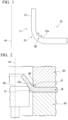
- the burring processed portion 11 of the burring processed product 10 has a curved portion 12 and an upright portion 13.
- compressive strain is generated on an inner surface 12a of the curved portion 12 in directions of arrows in the figure, and in-bend cracks CR are generated starting from unevenness caused by the compression strain.
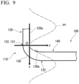
- the circumferential region 140 is a region surrounding the curved portion 130 in the burring processed product 100 and is a region connected to the base end portion 132 of the curved portion 130. Although it also depends on a shape of the burring processed product 100, the circumferential region 140 preferably has a width of about 1 to 10 mm in a radial direction of the burring processed portion 110 in a plane orthogonal to the axis cb of the burring processed portion 110.
- an approximating section may be narrowed so that the coefficient of determination is at least 0.9.
- the cross-sectional shape includes a straight line, in a case in which change rates of inclinations of adjacent straight lines are within plus or minus 2% for 3 or more consecutive sections when straight lines determined by the least squares method are sequentially created using five adjacent measurement points, the sections are determined to be a straight line.
- a range in which the cross-sectional shape of the inner surface of the curved portion has the above curve may be all range in a circumferential direction of the curved portion, or may be a part thereof.
- such a curved shape may be formed only in a range in which a load is intensely applied when the burring processed product is deformed by applying the load.
- the length l of the curved portion 130 may be at most 5.0 times or at most 2.0 times the height h.
- the method for manufacturing a burring processed product according to the present embodiment includes a burring processed portion forming process of increasing a diameter of a prepared hole provided in a metal component and bending a part of the metal component to form a burring processed portion including an upright portion and a curved portion.
- a cross-sectional shape of the curved portion on an inner surface thereof consists of a curve, and a length of the curved portion in a direction perpendicular to the axis of the burring processed portion is at least 1.2 times a height thereof in a direction parallel to the axis of the burring processed portion.
- a prepared hole forming process for forming the prepared hole in the metal component may be further provided.
- a burring processing method is a method for forming a burring processed portion on a metal component provided with a prepared hole using a mold including a die having a die hole, a holder, and a punch.
- the metal component is sandwiched between the die and the holder, and the punch is inserted into the die hole along an axis of the die hole to increase a diameter of the prepared hole and to bend a part of the metal component, thereby forming the burring processed portion including an upright portion and a curved portion.
- a cross-sectional shape of a die shoulder in a cross-section that passes through the axis of the die hole and is parallel to the axis of the die hole, a cross-sectional shape of a die shoulder consists of a curve, and a length thereof in a direction perpendicular to the axis of the die hole is at least 1.2 times a height thereof in a direction parallel to the axis of the die hole.
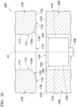
- Fig. 10 is a schematic cross-sectional view for describing the mold used in the burring processing method of the present embodiment.
- This cross-sectional view is a cross-sectional view that passes through the axis of the die hole and is parallel to the axis of the die hole.
- a mold 1000 includes a die 1100, a holder 1200, and a punch 1300.
- the die 1100 has a die hole 1110 having a predetermined depth.
- the die hole 1110 has a substantially cylindrical inner circumferential surface shape, and a cylindrical inner circumferential surface 1113 of the die hole 1110 and a die pressing surface 1130 are connected to each other via a die shoulder 1120.
- the die 1100 may be movable relative to the holder 1200 by a drive mechanism (not shown).
- a surface 1120a of the die shoulder 1120 is connected to the cylindrical inner circumferential surface 1113 at a tip portion 1121 and is connected to the die pressing surface 1130 via a base end portion 1122 on a side opposite to the tip portion 1121.
- a diameter of the surface 1120a of the die shoulder 1120 is increased from the tip portion 1121 toward the base end portion 1122.
- the surface 1120a of the die shoulder 1120 is smoothly curved in a cross-section that passes through an axis cd of the die hole 1110 and is parallel to the axis cd of the die hole 1110.
- a cross-sectional shape of the die shoulder 1120 means a shape of the surface 1120a of the die shoulder 1120 in the cross-section that passes through the axis cd of the die hole 1110 and is parallel to the axis cd of the die hole 1110.
- the axis cd of the die hole 1110 is an axis that passes through an axis line of the cylindrical inner circumferential surface 1113 in a height direction thereof.
- an axis of the punch 1300 and the axis of the die hole 1110 are preferably disposed to coincide with each other.
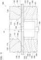
- Fig. 11 shows a state in which a workpiece 1 (metal component) is sandwiched between the die 1100 and the holder 1200.
- the punch 1300 may be housed inside the holder hole 1220 of the holder 1200.
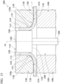
- Fig. 12 shows a state in which the punch 1300 is moved relative to the die 1100 in a direction from the holder 1200 to the die 1100 along the axis of the die hole 1110. As shown in Fig. 12 , the workpiece 1 is pressed into the die hole 1110 while being deformed by the punch 1300. Further, a diameter of the prepared hole 2 of the workpiece 1 is increased due to this deformation.
- Fig. 13 shows a state in which the punch 1300 reaches a predetermined position inside the die hole 1110, thereby completing burring processing.
- the punch 1300 is pulled out from the die hole 1110, and the die 1100 and the holder 1200 are moved relative to each other in a direction in which they are separated from each other.
- Fig. 14 is a diagram for describing the mold according to the present embodiment and is a cross-sectional view in the cross-section that passes through the axis cd of the die hole 1110 and is parallel to the axis cd of the die hole 1110.
- the cross-sectional shape of the die shoulder 1120 consists of a curve, and a length l d of the die shoulder 1120 in the direction perpendicular to the axis cd of the die hole 1110 is at least 1.2 times a height h d thereof in the direction parallel to the axis cd of the die hole 1110.
- a contact area between the workpiece and the die in the forming process can be increased, and thus swelling generated on the inner surface of the curved portion as described above can be inhibited. Further, with such a configuration, a contact between the workpiece and the mold at a high surface pressure can be prevented. For that reason, generation of in-bend cracks in the curved portion of the burring processed portion of the burring processed product can be inhibited. More specifically, by setting the length l d at least 1.2 times the height h d , cracking depths of the in-bend cracks can be reduced.
- the length l d of the die shoulder 1120 in the direction perpendicular to the axis cd of the die hole 1110 is more preferably at least 1.4 times, and further preferably at least 1.6 times the height h d in the direction parallel to the axis cd of the die hole 1110.
- the length l d is a distance from the tip portion 1121, which is the contact point between the cylindrical inner circumferential surface 1113 and the surface 1120a of the die shoulder 1120, to the base end portion 1122 of the die shoulder 1120 and is a distance in the direction perpendicular to the axis cd in the cross-section that passes through the axis cd of the die hole 1110 and is parallel to the axis cd of the die hole 1110.
- the length l d of the die shoulder 1120 is preferably 0.8 to 5.0 mm, and more preferably 1.0 to 2.5 mm.
- the height h d is a distance from the tip portion 1121, which is the contact point between the cylindrical inner circumferential surface 1113 and the surface 1120a of the die shoulder 1120, to the base end portion 1122 of the die shoulder 1120 and is a distance in the direction parallel to the axis cd in the cross-section that passes through the axis cd of the die hole 1110 and is parallel to the axis cd of the die hole 1110.
- the height h d of the die shoulder 1120 is preferably 0.5 to 3.0 mm, and more preferably 0.8 to 2.0 mm.
- the length l d of the die shoulder 1120 in the direction perpendicular to the axis cd of the die hole 1110 is more preferable at most 3.0 times the height h d in the direction parallel to the axis cd of the die hole 1110.
- a curve of the surface 1120a of the die shoulder 1120 can be defined as follows. As shown in Fig. 15 , in the cross-section that passes through the axis cd of the die hole 1110 and is parallel to the axis cd of the die hole 1110, a direction parallel to the axis cd is defined as the x axis, and a direction perpendicular to the axis cd in the cross-section is defined as the y axis. In addition, a contact point between the cylindrical inner circumferential surface 1113 and the surface 1120a of the die shoulder 1120 is defined as the origin O, and a side on which the die shoulder 1120 is located is defined as the positive region. A curve in the xy coordinates can be the curve drawn by the cross-sectional shape of the die shoulder 1120.
- the cross-sectional shape of the die shoulder 1120 consists of a curve in the cross-section that passes through the axis cd of the die hole 1110 and is parallel to the axis cd of the die hole 1110 and does not include a straight line.
- a part of the above curve drawn by the cross-sectional shape of the die shoulder 1120 may be a part of a curve represented by a quadratic function or a curve represented by a trigonometric function.
- a part of the above curve drawn by the cross-sectional shape of the die shoulder 1120 as a part of the curve represented by a quadratic function or a trigonometric function, generation of the in-bend cracks can be further inhibited.
- curves represented by quadratic or trigonometric functions include curves such as ellipses, parabolas, sine curves, and cosine curves.
- the definition and conditions of the curve represented by a quadratic function or a trigonometric function are the same as those in the first embodiment described above, but the length l of the curved portion 130 is replaced with the length l d of the die shoulder 1120, and the height h of the curved portion 130 is replaced with the height h d of the die shoulder 1120.
- the cross-sectional shape of the die shoulder 1120 may have a curve represented by a quadratic function or a trigonometric function over the entire region of the die shoulder 1120 starting from the origin O.
- the cross-sectional shape of the die shoulder 1120 may be a combination of a curve represented by a quadratic function or trigonometric function starting from the origin O and a smooth curve connected to the above curve and extending to the base end portion 132.
- a shape of the mold such as the die 1100 is measured using a contact type shape measuring machine.
- shape data is measured and acquired in the direction perpendicular to the axis cd of the die hole 1110 using a contact type shape measuring machine having a probe diameter of 2 mm.
- a data collection interval is set to 0.05 mm pitch in the direction parallel to the axis cd of the die hole 1110.
- the curve of the cross-sectional shape of the die shoulder 1120 is obtained by approximating the above shape data to the curve using the least squares method.
- the approximated curve is a quadratic function or trigonometric function as described above.
- a function with a coefficient of determination of at least 0.9 is used.
- the shape data measured in the process of obtaining the expression of the curve is approximated to several curves, and among them, one having a coefficient of determination of at least 0.9 and having the largest coefficient of determination is defined as the curve of the cross-sectional shape.
- the curve may be configured of a plurality of curves. For that reason, an approximating section may be narrowed so that the coefficient of determination is at least 0.9.
- the sections are determined to be a straight line.
- the punch 1300 has a cylindrical portion having a diameter smaller than a diameter of the die hole 1110, the punch 1300 can be inserted into the die hole 1110 along the axis of the die hole 1110, and when a clearance between the die hole 1110 and the cylindrical portion (the cylindrical inner circumferential surface 1113 of the die hole 1110 and the side circumferential surface 1310 of the punch 1300) is defined as cl, and a height of the cross-sectional shape of the die shoulder 1120 in the direction parallel to the axis of the die hole 1110 is defined as h d , the following Expression 3 may be satisfied. cl ⁇ 1.5 h d
- the clearance cl between the die hole 1110 and the cylindrical portion is a difference between a radius r d of the die hole 1110 and a radius p d of the punch 1300.
- the cylindrical portion may be the entire punch 1300 or a part of the punch 1300 including the side circumferential surface 1310.
- the range in which the cross-sectional shape of the die shoulder has the above curve may be the entire circumferential direction of the die shoulder, or may be a part thereof.
- the length l d of the die shoulder 1120 may be at most 5.0 times or at most 2.0 times the height h d .
- the mold of the present embodiment may be provided as a part of a burring processing device further including a drive mechanism that can move the die, the holder, and the punch relative to each other.
- a method for manufacturing a burring processed product includes a burring processed portion forming process of forming a burring processed portion on a metal component provided with a prepared hole using a mold including a die having a die hole, a holder, and a punch.
- a metal component is sandwiched between the die and the holder, and the punch is inserted into the die hole along an axis of the die hole to increase a diameter of the prepared hole and bend a part of the metal component, thereby forming the burring processed portion including an upright portion and a curved portion.
- a cross-sectional shape of a die shoulder in a cross-section that passes through the axis of the die hole and is parallel to the axis of the die hole, a cross-sectional shape of a die shoulder consists of a curve, and a length thereof in a direction perpendicular to the axis of the die hole is at least 1.2 times a height thereof in a direction parallel to the axis of the die hole.
- a burring processing method described in the third embodiment can be preferably used. Also, in the method for manufacturing a burring processed product according to the present embodiment, since each configuration of the third embodiment can be adopted, descriptions thereof will be omitted.
- a prepared hole forming process for forming the prepared hole in the metal component may be further provided before the burring processed portion forming process.
- the prepared hole is formed in the metal component or a metal plate, which is a workpiece, by punching, cutting with a tool, laser cutting, or the like.
- a height h of the curved portion 130 can be designed to be small.
- the height h is smaller than the plate thickness t as in Expression 1
- excessive compressive strain is generated inside the curved portion during forming, but in the burring processing method or the method for manufacturing a burring processed product according to the above embodiment, by inhibiting generation of such compression strain, generation of in-bend cracks can be inhibited.
- the height h of the curved portion may be the same as the height h d of the die shoulder.
- the plate thickness t around the prepared hole is a plate thickness at an edge portion of the prepared hole (an edge portion 2a of the prepared hole 2 in Figs. 3 and 4 , and the like).
- the burring processing method or the method for manufacturing a burring processed product according to the above embodiment may be an ironing burring processing method.
- an ironing burring processing method a clearance between a die and a punch is made smaller than a plate thickness of a workpiece, and the plate thickness of an upright portion is made smaller than the plate thickness of the workpiece.
- the in-bend cracks generated in the curved portion 130 of the burring processed portion 110 can be further inhibited. This is because the workpiece 1 is easily formed while being in contact with the die shoulder 1120 during forming, and buckling of a surface to the outside of the surface due to compressive strain that causes the in-bend cracks is inhibited.
- Patent Document 1 since the plate thickness is locally reduced and there is a curved portion having a small radius of curvature, a problem due to stress concentration may occur.
- the metal component may be a metal plate. Also, the metal components may be plated or painted.
- the plate thickness around the prepared hole is preferably at least 2.0 mm.
- a shape of the die shoulder corresponds to a shape of a portion formed in contact with the die shoulder in the product (burring processed product) and the shape of the die shoulder may be regarded as being reflected in the product as it is.
- the burring processing method or the method for manufacturing a burring product according to the above embodiment can be preferably used for a steel member having a tensile strength of at least 780 MPa.
- the burring processing method or the method for manufacturing a burring product according to the above embodiment can be preferably used for a steel member having a tensile strength of at least 980 MPa.
- the burring processing method or the method for manufacturing a burring product according to the above embodiment can be preferably used for a steel member having a tensile strength of at least 1180 MPa.
- a burring processed product has a burring processed portion including an upright portion and a curved portion, and in a cross-section that passes through an axis of the burring processed portion and is parallel to the axis of the burring processed portion, a cross-sectional shape of the curved portion on an inner surface thereof consists of a curve, and a length of the curved portion in a direction perpendicular to the axis of the burring processed portion is at least 1.2 times a height thereof in a direction parallel to the axis of the burring processed portion.
- burring processed product according to the present embodiment can adopt each configuration of the burring processed product described in the first embodiment, detailed descriptions thereof will be omitted.
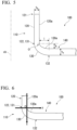
- the burring processed product according to the present embodiment is a lower arm used for a vehicle and may further have a cylindrical portion and a cylindrical flange portion.
- a plane that is perpendicular to the axis of the burring processed portion and passes through a center C in a length direction of the cylindrical portion on an axis of the cylindrical portion when an intersection between the axis of the burring processed portion and the plane is defined as an intersection A, an intersection between an axis of the cylindrical flange portion and the plane is defined as an intersection B, and a smaller one of angles between a line segment AB connecting the intersection A to the intersection B and a line segment AC connecting the intersection A to the center C is defined as ⁇ , and in the range of 20 from the line segment AB to a side on which the center C is located, and in the range of 2 ⁇ from the line segment AB to a side opposite to the side on which the center C is located, with the intersection A set as a center, in the cross-section that passes through the axis
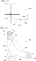
- FIG. 16 shows an example of a lower arm according to the present embodiment.
- a lower arm 200 includes a burring processed portion 210, a cylindrical portion 230, a cylindrical flange portion 250, a first element 270 connecting the burring processed portion 210 to the cylindrical portion 230, and a second element 290 connecting the first element 270 to the cylindrical flange portion 250. Also, depending on a shape of the lower arm 200, it may include the burring processed portion 210, the cylindrical portion 230, the cylindrical flange portion 250, the second element 290 connecting the burring processed portion 210 to the cylindrical flange portion 250, and the first element 270 connecting the second element 290 to the cylindrical portion 230.
- the cross-sectional shape of the curved portion on the inner surface consists of a curve, and the length of the curved portion in the direction perpendicular to the axis of the burring processed portion 210 is at least 1.2 times the height in the direction parallel to the axis of the burring processed portion 210.
- the length of the curved portion in the direction perpendicular to the axis of the burring processed portion 210 is more preferably at least 1.4 times, and further preferably at least 1.6 times the height in the direction parallel to the axis of the burring processed portion 210.
- Such a range in the circumferential direction of the burring processed portion 210 is referred to as a curve forming range 211.
- a plane that is perpendicular to the axis of the burring processed portion 210 (not shown) and passes through the center C in the length direction of the cylindrical portion 230 on the axis cc of the cylindrical portion 230 is defined.
- the paper surface of Fig. 16 is parallel to this plane.
- the axis of the burring processed portion 210 is orthogonal to the paper surface of Fig. 16 .
- intersection A The intersection between the axis of the burring processed portion 210 and the plane is defined as the intersection A, and the intersection between the axis of the cylindrical flange portion and the plane is defined as the intersection B. Further, a smaller one of angles between the line segment AB connecting the intersection A to the intersection B and the line segment AC connecting the intersection A to the center C is defined as 0.
- the curve forming range 211 having the above curve is provided in the range of 20 from the line segment AB to the side on which the center C is located and the range of 20 from the line segment AB to the side opposite to the side on which the center C is located, with the intersection A as a center.
- the curved portion in a range other than the curve forming range 211 may have a surface shape other than the above curve.
- the curved portion in the range other than the curve forming range 211 may be a curved portion having the same height as the curved portion in the curve forming range 211 and shorter than the length of the curved portion in the curve forming range 211.
- the curve forming range 211 be a range of ⁇ from the line segment AB to the side on which the center C is located and a range of 2 ⁇ from the line segment AB to the side opposite to the side on which the center C is located, with the intersection A as the center.
- Fig. 17 shows another example of the lower arm according to the present embodiment.
- the axis of the cylindrical portion 330 is located in a direction intersecting the paper surface of Fig. 17 .
- an orientation of the axis cc of the cylindrical portion 330 may be appropriately changed depending on a structure of a vehicle on which the lower arm is mounted.
- the burring processed product according to the present embodiment has no place in which the radius of curvature of the curved portion suddenly changes, so that a risk of stress concentration can be inhibited.
- the height of the upright portion of the burring processed portion is more preferably 2 to 20 mm.
- the burring processed product according to the present embodiment is not applied to a "structure in which it forms a closed cross-sectional shape by being superposed with another member (for example, a paired burring processed product)", but is preferably applied to a single-sheet structure basically configured of a single member.
- a contact area between an inner circumferential surface of the upright portion of the burring processed portion and a member inserted into the burring processed portion can be increased, stability of the member inserted in the burring processed portion can be ensured, and riding comfort can be improved.
- a prepared hole with a diameter of 42 mm was provided in a steel member having a tensile strength of 980 MPa and a plate thickness of 2.9 mm, and the prepared hole was subjected to burring processing with each mold under the following conditions.
- the cross-sectional shape of the die shoulder is a shape of a surface of the die shoulder in the cross-section that passes through the axis of the die hole and is parallel to the axis of the die hole, as described in the above embodiments.
- Table 1 shows results of presence or absence of generation of mold galling and presence or absence of generation of in-bend cracks in the case of the height h d of the die shoulder.
- the presence or absence of mold galling is visually determined, and a case in which there is no adhesion of the steel member to the mold (or the mold to the steel member) was designated as " ⁇ (good),” and a case in which the adhesion is observed was designated as " ⁇ (bad)”.
- Mold galling is adhesion between a material and a mold and is a phenomenon in which a part of a surface of a material sticks to a mold. Mold galling occurs when a material and a mold slide under high surface pressure, and when mold galling occurs, a product is scratched, resulting in poor quality.
- a prepared hole having a diameter of 42 mm was provided in a steel member having a tensile strength of 980 MPa and a plate thickness of 2.9 mm, and the prepared hole was subjected to burring processing with each mold under the following conditions.
- a cross-sectional shape of the die shoulder is a shape having a curved portion having a radius of curvature of 0.8 mm at a tip portion and a base end portion of the die shoulder and a straight portion between them, which is different from Comparative Example 1.
- Table 2 shows results of presence or absence of generation of mold galling and presence or absence of generation of in-bend cracks in the case of the height h d of the die shoulder and the length l d of the die shoulder. Evaluation criteria in Table 2 are the same as in Comparative Example 1.
- a prepared hole having a diameter of 42 mm was provided in a steel member having a tensile strength of 980 MPa and a plate thickness of 2.9 mm, and the prepared hole was subjected to burring processing with each mold under the following conditions.
- Example 1 burring processing was performed with each mold in which the height h d of the die shoulder and the length l d of the die shoulder were set to values shown in Table 3.
- Example 1 is different from Comparative Example 1 and Comparative Example 2 in that the cross-sectional shape of the die shoulder is a shape including a part of an ellipse.
- Table 3 shows results of presence or absence of generation of mold galling and presence or absence of generation of in-bend cracks in the case of the height h d of the die shoulder and the length l d of the die shoulder. Evaluation criteria in Table 3 are the same as in Comparative Example 1.
- a plate thicknesses of the steel member was 2.9 mm, and a prepared hole with a diameter of 42 mm was provided in the steel member, and the prepared hole was subjected to burring processing with each mold under the following conditions.
- the height h d of the die shoulder was fixed to 1.0 mm, and the length l d of the die shoulder was changed from 1.0 to 4.5 mm.
- the cross-sectional shape of the die shoulder was designed to be a part of the ellipse, the radius of the ellipse in a minor axis direction thereof was formed to correspond to the height h d of the die shoulder, and the radius of the ellipse in a major axis direction thereof was formed to correspond to the length l d of the die shoulder.
- Fig. 18 shows a graph of the cracking depths (um) in the case of the length l d (mm) of the die shoulder for each steel member.
- an arithmetic mean value of the cracking depths in these eight cross-sections is displayed as an "average value", and the maximum cracking depth among the cracking depths in the eight cross-sections is displayed as the "maximum value”.
- the burring processed portion is formed such that the cross-sectional shape of the curved portion on the inner surface consists of a curve, and the length of the curved portion in the direction perpendicular to the axis of the burring processed portion is at least 1.2 times the height in the direction parallel to the axis of the burring processed portion, and thus depths of the cracks generated in the burring processed portion can be inhibited.
- the present invention it is possible to provide a method for manufacturing a burring processed product, and a burring processed product in which generation of cracks in a curved portion of a burring processed portion can be inhibited, and thus the present invention has high industrial applicability.
Landscapes
- Engineering & Computer Science (AREA)
- Mechanical Engineering (AREA)
- Shaping Metal By Deep-Drawing, Or The Like (AREA)
- Punching Or Piercing (AREA)
Claims (11)
- Verfahren zur Herstellung eines entgrateten Produkts, umfassend einen Formungsprozess für ein entgrateten Abschnitt, bei dem ein Durchmesser einer vorbereiteten Bohrung (2) in einem Metallbauteil (1) vergrößert und ein Teil des Metallbauteils gebogen wird, um einen entgrateten Abschnitt (110) mit einem aufrechten Abschnitt (120) und einem gekrümmten Abschnitt (130) zu bilden,wobei in einem Querschnitt, der durch eine Achse des entgrateten Abschnitts verläuft und parallel zur Achse des entgrateten Abschnitts ist, eine Querschnittsform des gekrümmten Abschnitts an einer Innenfläche (130a) des gekrümmten Abschnitts aus einer Krümmung besteht, und dadurch gekennzeichnet ist, dasseine Länge des gekrümmten Abschnitts (110) in einer Richtung senkrecht zur Achse des entgrateten Abschnitts (110) mindestens das 1,2-fache einer Höhe des gekrümmten Abschnitts in einer Richtung parallel zur Achse des entgrateten Abschnitts beträgt.
- Verfahren zur Herstellung eines entgrateten Produkts gemäß Anspruch 1, das ferner einen Formungsprozess zum Formen einer vorbereiteten Bohrung umfasst zum Formen der vorbereiteten Bohrung in dem Metallbauteil vor dem Formungsprozess für den entgrateten Abschnitt.
- Verfahren zur Herstellung eines entgrateten Produkts gemäß einem der Ansprüche 1 bis 2, wobei, wenn eine Plattendicke um die vorbereitete Bohrung des Metallbauteils als t definiert ist, und eine Höhe des gekrümmten Abschnitts in einer Richtung parallel zur Achse des entgrateten Abschnitts als h definiert ist, die folgende Gleichung 1 erfüllt ist.

- Verfahren zur Herstellung eines entgrateten Produkts gemäß einem der Ansprüche 1 bis 3, wobei, wenn eine Plattendicke um die vorbereitete Bohrung des Metallbauteils als t definiert ist, und eine Plattendicke eines öffnungsseitigen Endabschnitts des aufrechten Abschnitts als tb definiert ist, die folgende Gleichung 2 erfüllt ist.
- Verfahren zur Herstellung eines entgrateten Produkts gemäß einem der Ansprüche 1 bis 4, wobei ein Wert, der durch zweimaliges Differenzieren einer die Kurve darstellenden Gleichung erhalten wird, größer als 0 ist.
- Entgratetes Produkt, das einen entgrateten Abschnitt (110) mit einem aufrechten Abschnitt (120) und einem gekrümmten Abschnitt (130) umfasst,
wobei in einem Querschnitt, der durch eine Achse des entgrateten Abschnitts verläuft und parallel zur Achse des entgrateten Abschnitts ist, eine Querschnittsform des gekrümmten Abschnitts an einer Innenfläche (130a) des gekrümmten Abschnitts aus einer Kurve besteht, und dadurch gekennzeichnet ist, dass
eine Länge des gekrümmten Abschnitts in einer Richtung senkrecht zur Achse des entgrateten Abschnitts mindestens das 1,2-fache einer Höhe des gekrümmten Abschnitts in einer Richtung parallel zur Achse des entgrateten Abschnitts beträgt. - Entgratungsprodukt nach Anspruch 6, wobei, wenn eine Plattendicke um den gekrümmten Abschnitt herum als t, definiert ist, und eine Höhe des gekrümmten Abschnitts in der Richtung parallel zur Achse des entgrateten Abschnitts als h definiert ist, die folgende Gleichung 4 erfüllt ist.

- Entgratungsprodukt gemäß Anspruch 6 oder 7, wobei, wenn eine Plattendicke um den gekrümmten Abschnitt herum als ts definiert ist, und eine Plattendicke eines öffnungsseitigen Endabschnitts des aufrechten Abschnitts als tb definiert ist, die folgende Gleichung 5 erfüllt ist.

- Entgratungsprodukt gemäß einem der Ansprüche 6 bis 8, wobei das Entgratungsprodukt ein unterer Lenker, ein Längslenker oder ein oberer Lenker ist, die in einem Fahrzeug verwendet werden.
- Entgratungsprodukt gemäß einem der Ansprüche 6 bis 8,wobei das entgratete Produkt ein in einem Fahrzeug verwendeter unterer Lenker ist, der ferner einen zylindrischen Abschnitt und einen zylindrischen Flanschabschnitt umfasst,in einer Ebene, die senkrecht zur Achse des entgrateten Abschnitts verläuft und durch einen Mittelpunkt C in Längsrichtung des zylindrischen Abschnitts auf einer Achse des zylindrischen Abschnitts verläuft,wobei, wenn ein Schnittpunkt zwischen der Achse des entgrateten Abschnitts und der Ebene als Schnittpunkt A definiert ist, ein Schnittpunkt zwischen einer Achse des zylindrischen Flanschabschnitts und der Ebene als Schnittpunkt B definiert ist, und der kleinere Winkel zwischen einem Liniensegment AB, das den Schnittpunkt A mit dem Schnittpunkt B verbindet, und einem Liniensegment AC, das den Schnittpunkt A mit dem Mittelpunkt C verbindet, als θ definiert ist, undim Bereich von 2θ von der Linie AB zu einer Seite, auf der sich der Mittelpunkt C befindet, und im Bereich von 2θ von der Linie AB zu einer Seite gegenüber der Seite, auf der sich der Mittelpunkt C befindet, mit dem Schnittpunkt A als ein Mittelpunkt,in dem Querschnitt, der durch die Achse des entgrateten Abschnitts verläuft und parallel zur Achse des entgrateten Abschnitts ist, besteht die Querschnittsform des gekrümmten Abschnitts auf der Innenfläche aus einer Kurve, und die Länge des gekrümmten Abschnitts in der Richtung senkrecht zur Achse des entgrateten Abschnitts beträgt mindestens das 1,2-fache der Höhe des gekrümmten Abschnitts in der Richtung parallel zur Achse des entgrateten Abschnitts.
- Entgratungsprodukt gemäß einem der Ansprüche 6 bis 10, wobei ein Wert, der durch zweimaliges Differenzieren einer die Kurve darstellenden Gleichung erhalten wird, größer als 0 ist.
Priority Applications (1)
| Application Number | Priority Date | Filing Date | Title |
|---|---|---|---|
| EP24197687.7A EP4534217A1 (de) | 2020-07-09 | 2021-07-09 | Entgratverarbeitungsverfahren, verfahren zur herstellung eines entgratverarbeitungsartikels, matrize für entgratverarbeitung, entgratverarbeitungsvorrichtung und entgratverarbeitungsartikel |
Applications Claiming Priority (2)
| Application Number | Priority Date | Filing Date | Title |
|---|---|---|---|
| JP2020118459 | 2020-07-09 | ||
| PCT/JP2021/025934 WO2022009978A1 (ja) | 2020-07-09 | 2021-07-09 | バーリング加工方法、バーリング加工品の製造方法、バーリング加工用金型、バーリング加工装置およびバーリング加工品 |
Related Child Applications (2)
| Application Number | Title | Priority Date | Filing Date |
|---|---|---|---|
| EP24197687.7A Division EP4534217A1 (de) | 2020-07-09 | 2021-07-09 | Entgratverarbeitungsverfahren, verfahren zur herstellung eines entgratverarbeitungsartikels, matrize für entgratverarbeitung, entgratverarbeitungsvorrichtung und entgratverarbeitungsartikel |
| EP24197687.7A Division-Into EP4534217A1 (de) | 2020-07-09 | 2021-07-09 | Entgratverarbeitungsverfahren, verfahren zur herstellung eines entgratverarbeitungsartikels, matrize für entgratverarbeitung, entgratverarbeitungsvorrichtung und entgratverarbeitungsartikel |
Publications (3)
| Publication Number | Publication Date |
|---|---|
| EP4180145A1 EP4180145A1 (de) | 2023-05-17 |
| EP4180145A4 EP4180145A4 (de) | 2024-03-27 |
| EP4180145B1 true EP4180145B1 (de) | 2025-06-25 |
Family
ID=79552519
Family Applications (2)
| Application Number | Title | Priority Date | Filing Date |
|---|---|---|---|
| EP24197687.7A Pending EP4534217A1 (de) | 2020-07-09 | 2021-07-09 | Entgratverarbeitungsverfahren, verfahren zur herstellung eines entgratverarbeitungsartikels, matrize für entgratverarbeitung, entgratverarbeitungsvorrichtung und entgratverarbeitungsartikel |
| EP21837611.9A Active EP4180145B1 (de) | 2020-07-09 | 2021-07-09 | Verfahren zur herstellung eines entgratverarbeitungsartikels und entgratverarbeitungsartikel |
Family Applications Before (1)
| Application Number | Title | Priority Date | Filing Date |
|---|---|---|---|
| EP24197687.7A Pending EP4534217A1 (de) | 2020-07-09 | 2021-07-09 | Entgratverarbeitungsverfahren, verfahren zur herstellung eines entgratverarbeitungsartikels, matrize für entgratverarbeitung, entgratverarbeitungsvorrichtung und entgratverarbeitungsartikel |
Country Status (6)
| Country | Link |
|---|---|
| US (1) | US12440882B2 (de) |
| EP (2) | EP4534217A1 (de) |
| JP (1) | JP7036288B1 (de) |
| CN (1) | CN115867397A (de) |
| MX (1) | MX2022016366A (de) |
| WO (1) | WO2022009978A1 (de) |
Families Citing this family (2)
| Publication number | Priority date | Publication date | Assignee | Title |
|---|---|---|---|---|
| WO2023195496A1 (ja) * | 2022-04-06 | 2023-10-12 | 日本製鉄株式会社 | バーリング構造部材 |
| DE102024101192A1 (de) * | 2024-01-16 | 2025-07-17 | Salzgitter Flachstahl Gmbh | Stahlblechbauteil für ein Arbeitsgerät einer Arbeitsmaschine und Verfahren zur Herstellung eines derartigen Stahlblechbauteils |
Family Cites Families (16)
| Publication number | Priority date | Publication date | Assignee | Title |
|---|---|---|---|---|
| JPS5844917A (ja) | 1981-09-09 | 1983-03-16 | Hitachi Ltd | バ−リングなどの加工方法 |
| JP2936469B2 (ja) * | 1996-09-20 | 1999-08-23 | 有限会社柿生精密 | 筒状嵌合物を溶着する為の溶着部をもつワークバーリング加工方法 |
| JP2003285121A (ja) * | 2002-03-27 | 2003-10-07 | Calsonic Kansei Corp | シール座面を有するフランジの形成方法およびその方法を用いて形成されたエキゾーストマニホールドのヘッドフランジ |
| GB2405678B (en) | 2003-09-03 | 2007-03-07 | Nsk Europ Ltd | A bearing assembly |
| JP2007275976A (ja) * | 2006-04-11 | 2007-10-25 | Fujifilm Corp | プレス金型、バーリング加工方法、プレス加工品の製造方法およびプレス加工品 |
| JP5202888B2 (ja) | 2007-06-29 | 2013-06-05 | 株式会社ヒロテック | 筒部付きフランジ継手の形成方法および筒部付きフランジ継手 |
| WO2010004899A1 (ja) * | 2008-07-10 | 2010-01-14 | 本田技研工業株式会社 | 車両用サスペンションアーム |
| DE102010006671A1 (de) * | 2010-02-03 | 2010-09-16 | Daimler Ag | Verfahren und Vorrichtung zum Abkanten von Blechbauteilen |
| JP6108876B2 (ja) * | 2012-08-20 | 2017-04-05 | 日立オートモティブシステムズ株式会社 | 枝管付チューブ、緩衝器及びこれらの製造方法 |
| JP3185738U (ja) * | 2013-06-20 | 2013-08-29 | サンコースプリング株式会社 | 開口構造 |
| JP2015083312A (ja) * | 2013-10-25 | 2015-04-30 | ダイハツ工業株式会社 | フランジ加工装置および加工方法 |
| KR102007106B1 (ko) * | 2015-03-11 | 2019-08-02 | 닛폰세이테츠 가부시키가이샤 | 버링 가공 방법 |
| JP6648624B2 (ja) * | 2016-04-26 | 2020-02-14 | 日本製鉄株式会社 | バーリング加工方法及びプレス成形装置 |
| JP7066315B2 (ja) | 2016-09-29 | 2022-05-13 | 日本製鉄株式会社 | バーリング加工装置、バーリング加工方法、金属部品の製造方法、バーリング加工品及び金属部品 |
| KR101880649B1 (ko) * | 2018-03-05 | 2018-08-17 | 안석진 | 차량용 로어암 제조방법 |
| JP2020118459A (ja) | 2019-01-18 | 2020-08-06 | Kddi株式会社 | 経路決定装置、コンピュータプログラム及び経路決定方法 |
-
2021
- 2021-07-09 EP EP24197687.7A patent/EP4534217A1/de active Pending
- 2021-07-09 MX MX2022016366A patent/MX2022016366A/es unknown
- 2021-07-09 CN CN202180047069.8A patent/CN115867397A/zh active Pending
- 2021-07-09 US US18/014,427 patent/US12440882B2/en active Active
- 2021-07-09 WO PCT/JP2021/025934 patent/WO2022009978A1/ja not_active Ceased
- 2021-07-09 JP JP2021561654A patent/JP7036288B1/ja active Active
- 2021-07-09 EP EP21837611.9A patent/EP4180145B1/de active Active
Also Published As
| Publication number | Publication date |
|---|---|
| JP7036288B1 (ja) | 2022-03-15 |
| WO2022009978A1 (ja) | 2022-01-13 |
| EP4180145A4 (de) | 2024-03-27 |
| EP4534217A1 (de) | 2025-04-09 |
| US12440882B2 (en) | 2025-10-14 |
| CN115867397A (zh) | 2023-03-28 |
| MX2022016366A (es) | 2023-01-30 |
| US20230241662A1 (en) | 2023-08-03 |
| JPWO2022009978A1 (de) | 2022-01-13 |
| EP4180145A1 (de) | 2023-05-17 |
Similar Documents
| Publication | Publication Date | Title |
|---|---|---|
| KR101996155B1 (ko) | 성형품의 제조 방법, 금형 및 관상 성형품 | |
| EP4180145B1 (de) | Verfahren zur herstellung eines entgratverarbeitungsartikels und entgratverarbeitungsartikel | |
| JP6512191B2 (ja) | 金型の設計方法およびプレス成形品の製造方法 | |
| EP3663012B1 (de) | Verfahren zur herstellung eines pressgeformten produkts | |
| KR20170070155A (ko) | 강관의 제조 방법 및 그 방법에 사용하는 프레스 금형 | |
| JP7036298B1 (ja) | バーリング加工部材 | |
| JP6133915B2 (ja) | 2次プレス加工性評価方法 | |
| CN114080280A (zh) | 坯料的制造方法及装置、冲压成型品的制造方法、形状判定方法及程序、以及坯料 | |
| EP4279192A1 (de) | Entgratungsverfahren, entgratmatrize, entgratungsvorrichtung und entgratter artikel | |
| Hirt et al. | Manufacturing of sheet metal parts from tailor rolled blanks | |
| JP2021122838A (ja) | 成形材製造方法 | |
| Wang et al. | Stretch flanging of “V”-shaped sheet metal blanks | |
| US10940518B2 (en) | Manufacturing method for press-formed article | |
| JP6173369B2 (ja) | プレス加工性評価装置及びプレス加工性評価方法 | |
| JP5423574B2 (ja) | 金属板の曲げ加工時の限界条件の決定方法及びプレス成形時の金属板の曲げ加工部の不具合の予測方法 | |
| JP7758140B1 (ja) | プレス成形品のねじれ評価方法、プレス成形品のねじれ評価装置及びプレス成形品のねじれ評価プログラム、並びにプレス成形品の製造方法 | |
| EP3960328B1 (de) | Präzisionsschmiedeverfahren, präzisionsschmiedevorrichtung und präzisionsschmiedeprodukt | |
| RU2626253C2 (ru) | Способ формообразования листовых деталей двоякой кривизны | |
| JP7648021B1 (ja) | 曲げ性能評価方法 | |
| JP7772136B1 (ja) | 金属板の成形限界取得方法、金属板の成形限界面作成方法、金属板の成形限界面作成システム及び金属板の成形限界面作成プログラム、並びに、プレス成形割れ判定方法、プレス成形割れ判定システム及びプレス成形割れ判定プログラム | |
| JPH06190492A (ja) | H形状断面を有する部材の成形方法 | |
| KR20250153239A (ko) | 금속제 가공품의 제조 방법 및 금속제 가공품 | |
| EP4474086A1 (de) | Stahlmaterial, automobilkomponente, schervorrichtung und herstellungsverfahren für stahlmaterial | |
| JP2024028215A (ja) | プレス部品の製造方法、プレス加工用の金属板、及びその製造方法 | |
| Thakkar et al. | Simulation based control of weld line movement in tailor welded blanks |
Legal Events
| Date | Code | Title | Description |
|---|---|---|---|
| STAA | Information on the status of an ep patent application or granted ep patent |
Free format text: STATUS: THE INTERNATIONAL PUBLICATION HAS BEEN MADE |
|
| PUAI | Public reference made under article 153(3) epc to a published international application that has entered the european phase |
Free format text: ORIGINAL CODE: 0009012 |
|
| STAA | Information on the status of an ep patent application or granted ep patent |
Free format text: STATUS: REQUEST FOR EXAMINATION WAS MADE |
|
| 17P | Request for examination filed |
Effective date: 20230105 |
|
| AK | Designated contracting states |
Kind code of ref document: A1 Designated state(s): AL AT BE BG CH CY CZ DE DK EE ES FI FR GB GR HR HU IE IS IT LI LT LU LV MC MK MT NL NO PL PT RO RS SE SI SK SM TR |
|
| DAV | Request for validation of the european patent (deleted) | ||
| DAX | Request for extension of the european patent (deleted) | ||
| A4 | Supplementary search report drawn up and despatched |
Effective date: 20240222 |
|
| RIC1 | Information provided on ipc code assigned before grant |
Ipc: B60G 7/00 20060101ALI20240216BHEP Ipc: B21D 19/08 20060101AFI20240216BHEP |
|
| GRAP | Despatch of communication of intention to grant a patent |
Free format text: ORIGINAL CODE: EPIDOSNIGR1 |
|
| STAA | Information on the status of an ep patent application or granted ep patent |
Free format text: STATUS: GRANT OF PATENT IS INTENDED |
|
| INTG | Intention to grant announced |
Effective date: 20250312 |
|
| GRAS | Grant fee paid |
Free format text: ORIGINAL CODE: EPIDOSNIGR3 |
|
| GRAA | (expected) grant |
Free format text: ORIGINAL CODE: 0009210 |
|
| STAA | Information on the status of an ep patent application or granted ep patent |
Free format text: STATUS: THE PATENT HAS BEEN GRANTED |
|
| AK | Designated contracting states |
Kind code of ref document: B1 Designated state(s): AL AT BE BG CH CY CZ DE DK EE ES FI FR GB GR HR HU IE IS IT LI LT LU LV MC MK MT NL NO PL PT RO RS SE SI SK SM TR |
|
| REG | Reference to a national code |
Ref country code: GB Ref legal event code: FG4D |
|
| REG | Reference to a national code |
Ref country code: CH Ref legal event code: EP |
|
| REG | Reference to a national code |
Ref country code: CH Ref legal event code: EP |
|
| REG | Reference to a national code |
Ref country code: IE Ref legal event code: FG4D |
|
| REG | Reference to a national code |
Ref country code: DE Ref legal event code: R096 Ref document number: 602021033029 Country of ref document: DE |
|
| PG25 | Lapsed in a contracting state [announced via postgrant information from national office to epo] |
Ref country code: FI Free format text: LAPSE BECAUSE OF FAILURE TO SUBMIT A TRANSLATION OF THE DESCRIPTION OR TO PAY THE FEE WITHIN THE PRESCRIBED TIME-LIMIT Effective date: 20250625 |
|
| PGFP | Annual fee paid to national office [announced via postgrant information from national office to epo] |
Ref country code: DE Payment date: 20250721 Year of fee payment: 5 |
|
| REG | Reference to a national code |
Ref country code: LT Ref legal event code: MG9D |
|
| PG25 | Lapsed in a contracting state [announced via postgrant information from national office to epo] |
Ref country code: GR Free format text: LAPSE BECAUSE OF FAILURE TO SUBMIT A TRANSLATION OF THE DESCRIPTION OR TO PAY THE FEE WITHIN THE PRESCRIBED TIME-LIMIT Effective date: 20250926 Ref country code: NO Free format text: LAPSE BECAUSE OF FAILURE TO SUBMIT A TRANSLATION OF THE DESCRIPTION OR TO PAY THE FEE WITHIN THE PRESCRIBED TIME-LIMIT Effective date: 20250925 |
|
| PG25 | Lapsed in a contracting state [announced via postgrant information from national office to epo] |
Ref country code: BG Free format text: LAPSE BECAUSE OF FAILURE TO SUBMIT A TRANSLATION OF THE DESCRIPTION OR TO PAY THE FEE WITHIN THE PRESCRIBED TIME-LIMIT Effective date: 20250625 |
|
| PG25 | Lapsed in a contracting state [announced via postgrant information from national office to epo] |
Ref country code: HR Free format text: LAPSE BECAUSE OF FAILURE TO SUBMIT A TRANSLATION OF THE DESCRIPTION OR TO PAY THE FEE WITHIN THE PRESCRIBED TIME-LIMIT Effective date: 20250625 |
|
| PGFP | Annual fee paid to national office [announced via postgrant information from national office to epo] |
Ref country code: AT Payment date: 20251020 Year of fee payment: 5 Ref country code: FR Payment date: 20250828 Year of fee payment: 5 |
|
| PG25 | Lapsed in a contracting state [announced via postgrant information from national office to epo] |
Ref country code: RS Free format text: LAPSE BECAUSE OF FAILURE TO SUBMIT A TRANSLATION OF THE DESCRIPTION OR TO PAY THE FEE WITHIN THE PRESCRIBED TIME-LIMIT Effective date: 20250925 |
|
| PG25 | Lapsed in a contracting state [announced via postgrant information from national office to epo] |
Ref country code: LV Free format text: LAPSE BECAUSE OF FAILURE TO SUBMIT A TRANSLATION OF THE DESCRIPTION OR TO PAY THE FEE WITHIN THE PRESCRIBED TIME-LIMIT Effective date: 20250625 |
|
| REG | Reference to a national code |
Ref country code: NL Ref legal event code: MP Effective date: 20250625 |
|
| PG25 | Lapsed in a contracting state [announced via postgrant information from national office to epo] |
Ref country code: NL Free format text: LAPSE BECAUSE OF FAILURE TO SUBMIT A TRANSLATION OF THE DESCRIPTION OR TO PAY THE FEE WITHIN THE PRESCRIBED TIME-LIMIT Effective date: 20250625 |