EP4155482B1 - Bauschalungsvorrichtung mit einem verriegelungselement - Google Patents
Bauschalungsvorrichtung mit einem verriegelungselement Download PDFInfo
- Publication number
- EP4155482B1 EP4155482B1 EP22177073.8A EP22177073A EP4155482B1 EP 4155482 B1 EP4155482 B1 EP 4155482B1 EP 22177073 A EP22177073 A EP 22177073A EP 4155482 B1 EP4155482 B1 EP 4155482B1
- Authority
- EP
- European Patent Office
- Prior art keywords
- building formwork
- tapered section
- section
- locking member
- hole
- Prior art date
- Legal status (The legal status is an assumption and is not a legal conclusion. Google has not performed a legal analysis and makes no representation as to the accuracy of the status listed.)
- Active
Links
Images


Classifications
-
- E—FIXED CONSTRUCTIONS
- E04—BUILDING
- E04G—SCAFFOLDING; FORMS; SHUTTERING; BUILDING IMPLEMENTS OR AIDS, OR THEIR USE; HANDLING BUILDING MATERIALS ON THE SITE; REPAIRING, BREAKING-UP OR OTHER WORK ON EXISTING BUILDINGS
- E04G17/00—Connecting or other auxiliary members for forms, falsework structures, or shutterings
- E04G17/04—Connecting or fastening means for metallic forming or stiffening elements, e.g. for connecting metallic elements to non-metallic elements
- E04G17/042—Connecting or fastening means for metallic forming or stiffening elements, e.g. for connecting metallic elements to non-metallic elements being tensioned by threaded elements
-
- E—FIXED CONSTRUCTIONS
- E04—BUILDING
- E04G—SCAFFOLDING; FORMS; SHUTTERING; BUILDING IMPLEMENTS OR AIDS, OR THEIR USE; HANDLING BUILDING MATERIALS ON THE SITE; REPAIRING, BREAKING-UP OR OTHER WORK ON EXISTING BUILDINGS
- E04G17/00—Connecting or other auxiliary members for forms, falsework structures, or shutterings
- E04G17/06—Tying means; Spacers ; Devices for extracting or inserting wall ties
- E04G17/065—Tying means, the tensional elements of which are threaded to enable their fastening or tensioning
-
- E—FIXED CONSTRUCTIONS
- E04—BUILDING
- E04G—SCAFFOLDING; FORMS; SHUTTERING; BUILDING IMPLEMENTS OR AIDS, OR THEIR USE; HANDLING BUILDING MATERIALS ON THE SITE; REPAIRING, BREAKING-UP OR OTHER WORK ON EXISTING BUILDINGS
- E04G11/00—Forms, shutterings, or falsework for making walls, floors, ceilings, or roofs
- E04G11/06—Forms, shutterings, or falsework for making walls, floors, ceilings, or roofs for walls, e.g. curved end panels for wall shutterings; filler elements for wall shutterings; shutterings for vertical ducts
-
- E—FIXED CONSTRUCTIONS
- E04—BUILDING
- E04G—SCAFFOLDING; FORMS; SHUTTERING; BUILDING IMPLEMENTS OR AIDS, OR THEIR USE; HANDLING BUILDING MATERIALS ON THE SITE; REPAIRING, BREAKING-UP OR OTHER WORK ON EXISTING BUILDINGS
- E04G19/00—Auxiliary treatment of forms, e.g. dismantling; Cleaning devices
- E04G19/003—Arrangements for stabilising the forms or for moving the forms from one place to another
-
- E—FIXED CONSTRUCTIONS
- E04—BUILDING
- E04G—SCAFFOLDING; FORMS; SHUTTERING; BUILDING IMPLEMENTS OR AIDS, OR THEIR USE; HANDLING BUILDING MATERIALS ON THE SITE; REPAIRING, BREAKING-UP OR OTHER WORK ON EXISTING BUILDINGS
- E04G9/00—Forming or shuttering elements for general use
- E04G9/08—Forming boards or similar elements, which are collapsible, foldable, or able to be rolled up
Definitions
- the disclosure relates to a building formwork apparatus having a locking member.
- An existing building formwork apparatus includes at least four formworks and at least one connecting hornbeam block.
- Each formwork has a mold surface at one side thereof, a mounting surface at the other side thereof, and two connecting posts disposed on upper and lower ends of the mounting surface.
- Each connecting post has a plurality of through holes.
- the connecting hornbeam block has a plurality of connecting holes.
- the connecting hornbeam block is then disposed on the connecting posts of the formworks, after which a plurality of fasteners are extended through the through holes and the connecting holes to fix the formworks and the connecting hornbeam block, thereby cooperatively forming the existing building formwork apparatus.
- the positioning of the formworks relies only on the connecting hornbeam block, so that, after assembly, the mold surfaces of the formworks are prone to misalign and become uneven. There is still room for improvement of the existing building formwork apparatus.
- an object of the present disclosure is to provide a building formwork apparatus that can alleviate at least one of the drawbacks of the prior art.
- the present invention is defined by claim 1 and concerns a building formwork apparatus of this disclosure comprising a building formwork and a locking member.
- the building formwork includes a wall plate and a frame disposed on the wall plate.
- the wall plate has a mounting surface and a mold surface opposite to the mounting surface.
- the frame is disposed on the mounting surface, and has at least one positioning hole and at least one locking hole.
- the locking hole has an internally threaded section.
- the locking member extends along and is rotatable about an axis, and includes a driven portion, a shoulder formed on one end of the driven portion, a positioning portion, and a threaded portion.
- the positioning portion includes a first tapered section connected to the shoulder, and a second tapered section connected to the first tapered section at a side opposite to the shoulder.
- the positioning portion gradually tapers from the first to the second tapered section in a direction away from the shoulder.
- Each of the first and second tapered sections has a cross section smaller than that of the shoulder.
- the threaded portion is connected to the second tapered section at a side opposite to the first tapered section, and has an external thread corresponding to the internally threaded section.
- the positioning hole is configured to receive insertion of the locking member therethrough such that the first tapered section of the locking member is retained in the positioning hole to restrict the locking member to rotate about the axis and such that the second tapered section of the locking member is exposed from the positioning hole for connection with another building formwork apparatus.
- the locking hole is adjacent to the positioning hole and is configured to receive a threaded portion and a second tapered section of a locking member of the another building formwork apparatus.
- the internally threaded section of the locking hole is configured to engage with the threaded portion of the another building formwork apparatus.
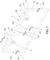
- a building formwork apparatus 100 according to an embodiment of the present disclosure is shown to comprise a locking member 1, a building formwork 2, and a hoist ring assembly 3. It should be noted herein that the number of the locking member 1 can be adjusted according to the requirement.
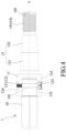
- the locking member 1 extends along and is rotatable about an axis (L), and includes a connecting rod portion 10, a driven portion 12, a shoulder 11, a positioning portion 13, and a threaded portion 14.
- the connecting rod portion 10 has a through hole 101 extending transversely through one end thereof.
- the driven portion 12 includes a surrounding wall 121, a groove 122 defined by the surrounding wall 121, a through hole 125 extending transversely through the surrounding wall 121 and communicating with the groove 122, and a threaded hole 126 diametrically opposed to the through hole 125.
- the shoulder 11 is formed on one end of the driven portion 12, and is cylindrical, but is not limited thereto.
- the connecting rod portion 10 has a shape corresponding to the groove 122, and is hexagonal, as shown in FIG. 5 .
- the connecting rod portion 10 has the one end inserted into the groove 122 along the axis (L), and through a fixing bolt 123 that extends through the through holes 125 and 101 and threadedly engages the threaded hole 126, the one end of the connecting rod portion 10 is fixed inside the groove 122, thereby preventing separation of the connecting rod portion 10 from the driven portion 12.
- the connecting rod portion 10 is rotated, the driven portion 12 is driven by the connecting rod portion 10 to rotate therewith.
- the connecting rod portion 10 thereof may be replaced by a hand tool (such as a drive rod, not shown) to drive the driven portion 12 to rotate therewith. Since the modification of the locking member 1 does not need the connecting rod portion 10, a protruding portion thereof may be reduced.
- the positioning portion 13 has a conical shape, and includes a first tapered section 131 connected to the shoulder 11, and a second tapered section 132 connected to the first tapered section 131 at a side opposite to the shoulder 11.
- the positioning portion 13 gradually tapers from the first tapered section 131 to the second tapered section 132 in a direction away from the shoulder 11 along the axis (L).
- Each of the first and second tapered sections 131, 132 has a cross section smaller than that of the shoulder 11.
- the first and second tapered sections 131, 132 are integrally formed as a single piece, and each of the first and second tapered sections 131, 132 has a taper ratio of 1:8.
- the shoulder 11 and the positioning portion 13 are integrally formed as a single piece.
- the threaded portion 14 is connected to the second tapered section 132 at a side opposite to the first tapered section 131, and has an outer peripheral surface 142 formed with an external thread 141.
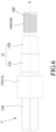
- FIG. 6 An alternative form of the locking member 1' is shown in FIG. 6 .
- the locking member 1' does not include the connecting rod portion 10 (see FIGS. 3 and 4 ), and the driven portion 12' thereof has a protruding post 124 that is polygonal and that protrudes in a direction opposite to the shoulder 11.
- the shoulder 11 and the driven portion 12' are integrally formed as a single piece, so that the fixing bolt 123 (see FIG. 4 ) can be omitted.
- a hand tool (such as a wrench, not shown) can be inserted into or can clamp the protruding post 124 for rotation therewith.
- the building formwork 2 includes a wall plate 21 and a frame 22.
- the wall plate 21 has a mounting surface 211 and a mold surface 212 opposite to the mounting surface 211.
- the frame 22 is disposed on the mounting surface 211, and has a plurality of positioning holes 221 and a plurality of locking holes 222.
- Each positioning hole 221 has a large-diameter section 223 corresponding to the driven portion 12, a first tapered hole section 224 corresponding to the first tapered section 131, and a shoulder 227 between the large-diameter section 223 and the first tapered hole section 224.
- Each locking hole 222 has an internally threaded section 225 corresponding to the external thread 141, and a second tapered hole section 226 corresponding to the second tapered section 132.
- Each locking hole 222 is adjacent to a respective one of the positioning holes 221.
- the hoist ring assembly 3 is provided on the mounting surface 211 of the wall plate 21 to facilitate lifting and moving of the building formwork 2.
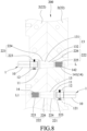
- the building formwork apparatus 100 of this embodiment may further comprise another locking member 1, so that a plurality of the building formwork apparatuses 100 (only two are shown) may be assembled to form a formwork wall 200. Since interconnection between each two adjacent building formwork apparatuses 100 are similar, only two adjacent building formwork apparatuses 100 will be described hereinafter.
- the two building formwork apparatuses 100 are placed side by side horizontally, after which the locking member 1 of a left building formwork apparatus 100 is inserted into the positioning hole 221 of the building formwork 2 thereof with the driven portion 12, the shoulder 11 and the first tapered section 131 thereof positioned therein, while the second tapered section 132 and the threaded portion 14 thereof extending out of the positioning hole 221 and inserted into an aligned locking hole 222 in the building formwork 2 of a right building formwork apparatus 100.
- the locking member 1 of the right building formwork apparatus 100 is inserted into the positioning hole 221 of the building formwork 2 thereof with the driven portion 12, the shoulder 11 and the first tapered section 131 thereof positioned therein, while the second tapered section 132 of the positioning portion 13 and the threaded portion 14 thereof extending out of the positioning hole 221 and inserted into an aligned locking hole 222 in the building formwork 2 of the left building formwork apparatus 100.
- the connecting rod portion 10 of the locking member 1 of each building formwork apparatus 100 is rotated to engage the threaded portion 14 with the internally threaded section 225 of the aligned locking hole 222 until the shoulder 11 abuts against the shoulder 227.
- the two building formwork apparatuses 100 are moved toward each other and abut against each other. Hence, assembly of the two building formwork apparatuses 100 is completed.
- the formwork wall 200 extending in the horizontal direction can be formed.
- the two building formwork apparatuses 100 may be stacked one above the other, after which the locking member 1 of an upper building formwork apparatus 100 is inserted through the positioning hole 221 of the building formwork 2 thereof into an aligned locking hole 222 in the building formwork 2 of a lower building formwork apparatus 100.
- the locking member 1 of the lower building formwork apparatus 100 is inserted through the positioning hole 221 of the building formwork 2 thereof into an aligned locking hole 222 in the building formwork 2 of the upper building formwork apparatus 100.
- each building formwork apparatus 100 is rotated to engage the threaded portion 14 with the internally threaded section 225 of the aligned locking hole 222, thereby moving the two building formwork apparatuses 100 toward each other and to abut against each other. Hence, assembly of the two stacked building formwork apparatuses 100 is completed.
- the formwork wall 200 extending in the vertical direction can be formed.
- the locking member 1 is rotated using a hand tool, such as a wrench (not shown) . Further, with the driven portion 12, the shoulder 11 and the first tapered section 131 of the locking member 1 inserted into the positioning hole 221 of the frame 22 of the building formwork 2, deflection of the axis (L) can be limited.
- the frames 22 of the building formworks 2 of the building formwork apparatuses 100 disposed on the mounting surfaces 211 of the wall plates 21 thereof can be flush with each other, and the mold surfaces of the wall plates 21 of the building formworks 2 can also be flush with each other to facilitate subsequent process.
- the deflection of the axis (L) can be restricted to maintain stability of rotation during assembly; and after the assembly of the plurality of the building formwork apparatuses 100 that are arranged either horizontally or vertically to form the formwork wall 200, the mold surfaces 212 of the wall plates 21 of the building formworks 2 of the building formwork apparatuses 100 can be flush with each other. Therefore, the object of this disclosure can indeed be achieved.
Landscapes
- Engineering & Computer Science (AREA)
- Architecture (AREA)
- Mechanical Engineering (AREA)
- Civil Engineering (AREA)
- Structural Engineering (AREA)
- Forms Removed On Construction Sites Or Auxiliary Members Thereof (AREA)
Claims (7)
- Eine Bauschalungsvorrichtung (100), die folgende Merkmale aufweist:eine Bauschalung (2), die eine Wandplatte (21) und einen Rahmen (22), der an der Wandplatte (21) angeordnet ist, umfasst, wobei die Wandplatte (21) eine Befestigungsoberfläche (211) und eine Formoberfläche (212) gegenüber der Befestigungsoberfläche (211) aufweist, wobei der Rahmen (22) an der Befestigungsoberfläche (211) angeordnet ist, und zumindest ein Positionierungsloch (221) und zumindest ein Verriegelungsloch (222) aufweist, wobei das Verriegelungsloch (222) einen Innengewindebereich (225) aufweist; undein Verriegelungsbauglied (1, 1'), das sich entlang einer Achse (L) erstreckt und um dieselbe drehbar ist, und folgende Merkmale umfassteinen angetriebenen Abschnitt (12, 12'),einen Absatz (11), der an einem Ende des angetriebenen Abschnitts (12, 12') gebildet ist,einen Positionierungsabschnitt (13), der einen ersten sich verjüngenden Bereich (131) umfasst, der mit dem Absatz (11) verbunden ist, und einen zweiten sich verjüngenden Bereich (132), der an einer Seite gegenüber dem Absatz (11) mit dem ersten sich verjüngenden Bereich (131) verbunden ist, wobei der Positionierungsabschnitt (13) von dem ersten spitz zu laufenden Bereich (131) zu dem zweiten sich verjüngenden Bereich (132) graduell in einer Richtung von dem Absatz (11) weg spitz zuläuft, wobei jeder des ersten sich verjüngenden Bereichs (131) und des zweiten sich verjüngenden Bereichs (132) einen Querschnitt aufweist, der kleiner als der des Absatzes (11) ist, undeinen Gewindeabschnitt (14), der an einer Seite gegenüber dem ersten sich verjüngenden Bereich (131) mit dem zweiten sich verjüngenden Bereich (132) verbunden ist, wobei der Gewindeabschnitt (14) ein Außengewinde (141) aufweist, das dem Innengewindebereich (225) des Verriegelungslochs (222) entspricht;wobei das Positionierungsloch (221) dazu konfiguriert ist, dass das Verriegelungsbauglied (1, 1') durch dasselbe hindurch derart eingeführt wird, dass der erste sich verjüngende Bereich (131) des Verriegelungsbauglieds (1, 1') in dem Positionierungsloch (221) gehalten wird, um das Verriegelungsbauglied (1, 1') zu begrenzen, damit sich dasselbe um die Achse (L) dreht, und derart, dass der zweite sich verjüngende Bereich (132) des Verriegelungsbauglieds (1, 1') von dem Positionierungsloch (221) zur Verbindung mit einer weiteren Bauschalungsvorrichtung (100) freiliegend ist; undwobei das Verriegelungsloch (222) dazu konfiguriert ist, einen Gewindeabschnitt (14) und einen zweiten sich verjüngenden Bereich (132) eines Verriegelungsbauglieds (1, 1') der weiteren Bauschalungsvorrichtung (100) aufzunehmen, wobei der Innengewindebereich (225) des Verriegelungslochs (222) dazu konfiguriert ist, mit dem Gewindeabschnitt (14) der weiteren Bauschalungsvorrichtung (100) in Eingriff zu kommen;wobei das Positionierungsloch (221) einen Bereich (223) mit großem Durchmesser aufweist, der dem angetriebenen Abschnitt (12, 12') entspricht;dadurch gekennzeichnet, dassdas Verriegelungsloch (222) zu dem Positionierungsloch (221) benachbart ist, unddas Positionierungsloch (221) einen ersten sich verjüngenden Lochbereich (224) aufweist, der dem ersten sich verjüngenden Bereich (131) des Positionierungsabschnitts (13) entspricht, wobei das Verriegelungsloch (222) ferner einen zweiten sich verjüngenden Lochbereich (226) aufweist, der dem zweiten sich verjüngenden Bereich (132) des Positionierungsabschnitts (13) entspricht.
- Die Bauschalungsvorrichtung (100) gemäß Anspruch 1, bei der der angetriebene Abschnitt (12) des Verriegelungsbauglieds (1) eine Umgebungswand (121) und eine Rille (122), die durch die Umgebungswand (121) definiert ist, umfasst.
- Die Bauschalungsvorrichtung (100) gemäß Anspruch 2, bei der das Verriegelungsbauglied (1) ferner einen Verbindungsstangenabschnitt (10) umfasst, der in der Rille (122) aufgenommen ist und eine Form aufweist, die der der Rille (122) entspricht.
- Die Bauschalungsvorrichtung (100) gemäß Anspruch 1, bei der der angetriebene Abschnitt (12') des Verriegelungsbauglieds (1') einen vorstehenden Stab (124) aufweist, der in eine Richtung gegenüber dem Absatz (11) vorsteht.
- Die Bauschalungsvorrichtung (100) gemäß Anspruch 4, bei der der vorstehende Stab (124) polygonal ist.
- Die Bauschalungsvorrichtung (100) gemäß einem der Ansprüche 1 bis 5, bei der der erste sich verjüngende Bereich (131) und der zweite sich verjüngende Bereich (132) einstückig als ein einzelnes Stück gebildet sind.
- Die Bauschalungsvorrichtung (100) gemäß einem der Ansprüche 1 bis 6, bei der jeder des ersten sich verjüngenden Bereichs (131) und des zweiten sich verjüngenden Bereichs (132) ein Verjüngungsverhältnis von 1:8 aufweist.
Applications Claiming Priority (1)
| Application Number | Priority Date | Filing Date | Title |
|---|---|---|---|
| TW110135146A TWI800001B (zh) | 2021-09-22 | 2021-09-22 | 具有鎖固件的建築模板裝置 |
Publications (2)
| Publication Number | Publication Date |
|---|---|
| EP4155482A1 EP4155482A1 (de) | 2023-03-29 |
| EP4155482B1 true EP4155482B1 (de) | 2024-08-07 |
Family
ID=81941012
Family Applications (1)
| Application Number | Title | Priority Date | Filing Date |
|---|---|---|---|
| EP22177073.8A Active EP4155482B1 (de) | 2021-09-22 | 2022-06-02 | Bauschalungsvorrichtung mit einem verriegelungselement |
Country Status (7)
| Country | Link |
|---|---|
| US (1) | US11976478B2 (de) |
| EP (1) | EP4155482B1 (de) |
| JP (1) | JP7397127B2 (de) |
| KR (1) | KR102741391B1 (de) |
| CN (1) | CN115897992A (de) |
| PL (1) | PL4155482T3 (de) |
| TW (1) | TWI800001B (de) |
Families Citing this family (5)
| Publication number | Priority date | Publication date | Assignee | Title |
|---|---|---|---|---|
| TWD218446S (zh) * | 2021-08-30 | 2022-04-21 | 王建和 | 鎖固件 |
| TWD219304S (zh) * | 2021-08-30 | 2022-06-11 | 王建和 | 鎖固裝置之部分 |
| TWD218620S (zh) * | 2021-08-30 | 2022-05-01 | 王建和 | 鎖固裝置的部分 |
| CN116856679B (zh) * | 2023-08-03 | 2025-11-04 | 中国建筑第八工程局有限公司 | 带有锁紧机构的建筑模板 |
| CN118668916B (zh) * | 2024-06-24 | 2025-09-30 | 中建八局第二建设有限公司 | 一种用于建筑工程浇筑定型模板 |
Citations (2)
| Publication number | Priority date | Publication date | Assignee | Title |
|---|---|---|---|---|
| FR2566821A1 (fr) * | 1984-07-02 | 1986-01-03 | Ricouard Marcel | Dispositif d'assemblage formant verrou auto-aligneur et inamovible pour l'assemblage de deux banches contigues |
| EP3760814A1 (de) * | 2018-02-26 | 2021-01-06 | Deguchi, Shinpei | Stopfen für betonförderrohr |
Family Cites Families (49)
| Publication number | Priority date | Publication date | Assignee | Title |
|---|---|---|---|---|
| US1364736A (en) * | 1919-08-21 | 1921-01-04 | Steve Mihalkevicz | Lock |
| US1382758A (en) * | 1919-10-16 | 1921-06-28 | Martha A Brown | Sash-fastener |
| US1410829A (en) * | 1919-11-22 | 1922-03-28 | Morgenthau Bernard | Lock |
| US1424136A (en) * | 1921-05-12 | 1922-07-25 | Morgenthau Bernard | Lock |
| CH113786A (de) * | 1925-01-30 | 1926-02-01 | Jules Suchsland | Kopfschraube. |
| US2297899A (en) * | 1941-03-25 | 1942-10-06 | Flangelock Patents Corp | Structural form for concrete and locking means therefor |
| US2526381A (en) * | 1948-03-17 | 1950-10-17 | William R Mathis | Molding apparatus |
| JPS4729677Y1 (de) | 1969-03-29 | 1972-09-05 | ||
| US3872904A (en) * | 1972-11-24 | 1975-03-25 | John W Barlow | Flex coupling fastener |
| ZA76128B (en) * | 1976-01-09 | 1977-02-23 | A Carter | Anchor screw and extractor therefor |
| FR2470220A1 (fr) * | 1979-11-21 | 1981-05-29 | Husson Et Cie Sa Roland | Banche pour la realisation de murs, ou analogues |
| FR2544356B1 (fr) | 1983-04-18 | 1987-07-17 | Pujol Barcons Salvador | Ensemble de construction pour la coulee de structures rigides monolithiques et procede de construction de telles structures |
| JPS61127911A (ja) | 1984-11-24 | 1986-06-16 | 吉江 勝廣 | 螺子 |
| US5104070A (en) * | 1989-06-01 | 1992-04-14 | Space Industries, Inc. | Structural latch for vehicle coupling mechanisms |
| US5174909A (en) * | 1990-01-18 | 1992-12-29 | Western Forms, Inc. | Latching bolt mechanism and mount for concrete forming system |
| US5288051A (en) * | 1990-01-18 | 1994-02-22 | Western Forms, Inc. | Latching bolt mechanism with lubricant reservoir for concrete forming system |
| JPH0562716U (ja) * | 1992-02-03 | 1993-08-20 | 株式会社ハーモニック・ドライブ・システムズ | 締結装置 |
| US5265836A (en) * | 1992-07-01 | 1993-11-30 | Dale, Cox & Simon | Concrete form |
| JP2623200B2 (ja) | 1992-10-28 | 1997-06-25 | 日綜産業株式会社 | 型枠装置 |
| US5686010A (en) * | 1995-02-17 | 1997-11-11 | Lee; Wen-Yuan | Connecting device for form panels |
| TW363103B (en) * | 1996-04-24 | 1999-07-01 | yong-chuan Zhuang | Horizontal supporting table for easy operation of moldboards |
| JPH1130215A (ja) * | 1997-07-07 | 1999-02-02 | Haruhiko Yanagihara | 三角穴木ネジと三角ドライバー |
| JP3974991B2 (ja) | 1998-02-05 | 2007-09-12 | 本田技研工業株式会社 | 樹脂製部材の締結構造 |
| CA2345544C (en) | 1998-09-29 | 2009-07-14 | Siemens Aktiengesellschaft | Method and arrangement for processing a digitized picture with pixels |
| US6428061B1 (en) * | 1999-06-09 | 2002-08-06 | Avaya Technology Corp. | Retractable safety mechanism for a cabinet |
| US6691976B2 (en) * | 2000-06-27 | 2004-02-17 | Feather Lite Innovations, Inc. | Attached pin for poured concrete wall form panels |
| DE10119799A1 (de) * | 2001-04-23 | 2002-10-24 | Hilti Ag | Nagelförmiges Befestigungselement |
| FR2851308A1 (fr) * | 2003-02-19 | 2004-08-20 | Andre Carossino | Vis de fixation destinee notamment a l'industrie mecanique |
| JP2005042877A (ja) | 2003-07-25 | 2005-02-17 | Sanshin Kogyo Kk | 部材の接合構造 |
| CN2806857Y (zh) * | 2005-04-22 | 2006-08-16 | 成都依姆特高科技有限责任公司 | 螺栓型定位紧固装置 |
| FR2897376B1 (fr) * | 2006-02-13 | 2008-05-16 | Mesa Imalat Sanayii Ve Ticaret | Systeme de coffrage perfectionne pour batiment ou travaux publics. |
| FR2904022B1 (fr) | 2006-07-18 | 2011-12-09 | Hussor | Dispositif d'assemblage des rives verticales de banches |
| ITMI20071227A1 (it) | 2007-06-19 | 2008-12-20 | Milano Politecnico | Dispositivo di fissaggio di elementi sovrapposti. |
| DE102009044357A1 (de) * | 2009-10-29 | 2011-05-05 | Fischerwerke Gmbh & Co. Kg | Kombination aus Schraubendreher und Schraube sowie Schraube |
| JP5493848B2 (ja) | 2009-12-28 | 2014-05-14 | 株式会社大林組 | 鋼製型枠をなす側板端部同士の接合構造 |
| US8864100B2 (en) * | 2010-02-08 | 2014-10-21 | Philip T. Ward | Formwork connecting pin assembly |
| KR20120017693A (ko) * | 2010-08-19 | 2012-02-29 | 조순화 | 렌치볼트 및 그 제조방법 |
| DE202010012699U1 (de) * | 2010-09-17 | 2010-12-09 | Emka Beschlagteile Gmbh & Co. Kg | Drehspannverschluss mit Erkennbarkeit der Verschlussstellung |
| DE102010038067B4 (de) | 2010-10-08 | 2014-07-17 | Wolfgang Weiss | Formschlussverbindung mit Ausgleich von Lagefehlern |
| CN201902114U (zh) * | 2010-12-22 | 2011-07-20 | 宁波驰球安防设备有限公司 | 一种用于保险箱柜门板锁定的旋转机构 |
| JP3182061U (ja) | 2012-12-21 | 2013-03-07 | 幸三郎 高木 | 型枠保持用コーン、およびその型枠保持用コーンを取外すために使用するスクリュードライバー |
| CN204456830U (zh) * | 2015-01-30 | 2015-07-08 | 张新盈 | 连接式建筑模板 |
| TWM519686U (zh) * | 2015-11-12 | 2016-04-01 | hong-yi Xu | 螺絲 |
| KR101850948B1 (ko) | 2016-01-05 | 2018-04-23 | 서울시립대학교 산학협력단 | 친환경 거푸집 모듈 및 이를 이용한 목조 건축물의 시공 방법 |
| FR3079540B1 (fr) * | 2018-03-29 | 2021-10-29 | Outinord St Amand | Dispositif de coffrage a montage ameliore |
| US11173589B2 (en) * | 2018-11-06 | 2021-11-16 | Bryce Fastener Company, Inc. | Methods and apparatus for a fastener head having a dual zone socket area and a mating driver bit |
| TWI716319B (zh) | 2020-05-14 | 2021-01-11 | 宏帝德物創股份有限公司 | 建築用模板 |
| DE102020004179B4 (de) * | 2020-07-11 | 2023-11-16 | ORTHO HUB VENTURES UG (haftungsbeschränkt) | Schraubenelement und System bestehend aus einem Schraubendreher und mindestens einem solchen Schraubenelement |
| CN112593701B (zh) * | 2020-11-26 | 2021-12-14 | 中核华辰工程管理有限公司 | 一种柱模板结构及施工方法 |
-
2021
- 2021-09-22 TW TW110135146A patent/TWI800001B/zh active
-
2022
- 2022-03-16 CN CN202210256403.7A patent/CN115897992A/zh active Pending
- 2022-05-27 US US17/826,453 patent/US11976478B2/en active Active
- 2022-06-02 PL PL22177073.8T patent/PL4155482T3/pl unknown
- 2022-06-02 EP EP22177073.8A patent/EP4155482B1/de active Active
- 2022-06-10 JP JP2022094385A patent/JP7397127B2/ja active Active
- 2022-06-30 KR KR1020220080644A patent/KR102741391B1/ko active Active
Patent Citations (2)
| Publication number | Priority date | Publication date | Assignee | Title |
|---|---|---|---|---|
| FR2566821A1 (fr) * | 1984-07-02 | 1986-01-03 | Ricouard Marcel | Dispositif d'assemblage formant verrou auto-aligneur et inamovible pour l'assemblage de deux banches contigues |
| EP3760814A1 (de) * | 2018-02-26 | 2021-01-06 | Deguchi, Shinpei | Stopfen für betonförderrohr |
Also Published As
| Publication number | Publication date |
|---|---|
| TW202314093A (zh) | 2023-04-01 |
| TWI800001B (zh) | 2023-04-21 |
| JP7397127B2 (ja) | 2023-12-12 |
| KR102741391B1 (ko) | 2024-12-10 |
| PL4155482T3 (pl) | 2024-12-16 |
| KR20230042623A (ko) | 2023-03-29 |
| CN115897992A (zh) | 2023-04-04 |
| US11976478B2 (en) | 2024-05-07 |
| EP4155482A1 (de) | 2023-03-29 |
| US20230092718A1 (en) | 2023-03-23 |
| JP2023046238A (ja) | 2023-04-03 |
Similar Documents
| Publication | Publication Date | Title |
|---|---|---|
| EP4155482B1 (de) | Bauschalungsvorrichtung mit einem verriegelungselement | |
| US20230093561A1 (en) | Locking member for building formworks | |
| US10760264B2 (en) | Assembling structure of prefabricated concrete component | |
| KR102078624B1 (ko) | 조정 가능한 콤팩트한 잭킹 커플러 및 이용 방법 | |
| EP4155480B1 (de) | Modulare bauschalungsvorrichtung mit verriegelungsvorrichtung | |
| EP4155481B1 (de) | Verriegelungsvorrichtung für modulare bauschalungen | |
| CN211666259U (zh) | 墙柱铝模板拼装结构 | |
| WO2022083701A1 (zh) | 建筑模块及其连接结构 | |
| KR20110118399A (ko) | 패스트 기둥 웨일러 | |
| KR20180000638U (ko) | 길이 조절이 가능한 안전 난간대 | |
| KR102328220B1 (ko) | 거푸집 연결장치 | |
| EP4247604A1 (de) | Nagelplatte geeignet zum halten einer gewindebuchse beim giessen von beton in eine schalung | |
| CN115075229A (zh) | 一种建筑模板固定装置 | |
| CN220889557U (zh) | 调节装置及装配式建筑 | |
| KR100931532B1 (ko) | 갱폼시스템의 고정장치 | |
| CN220226241U (zh) | 一种模板夹具 | |
| RU2513515C2 (ru) | Способ выравнивания телескопической вертикальной трубы с навершием или основанием | |
| CN218205695U (zh) | 一种建筑工程房建施工用吊模装置 | |
| CN112277135B (zh) | 一种用于钢筋混凝土的可调式预制框架体机构 | |
| KR101875008B1 (ko) | 핀 타입 서포트 높이조절 부재 | |
| KR102701600B1 (ko) | 높이 조절이 가능한 베이스 잭 | |
| CN217343147U (zh) | 冲压模具 | |
| CN116411727A (zh) | 一种建筑改造外墙加固装置及方法 | |
| CN215038556U (zh) | 一种u型砌块成型模具 | |
| CN210104775U (zh) | 地面固定系统和起钉器 |
Legal Events
| Date | Code | Title | Description |
|---|---|---|---|
| PUAI | Public reference made under article 153(3) epc to a published international application that has entered the european phase |
Free format text: ORIGINAL CODE: 0009012 |
|
| STAA | Information on the status of an ep patent application or granted ep patent |
Free format text: STATUS: THE APPLICATION HAS BEEN PUBLISHED |
|
| STAA | Information on the status of an ep patent application or granted ep patent |
Free format text: STATUS: REQUEST FOR EXAMINATION WAS MADE |
|
| AK | Designated contracting states |
Kind code of ref document: A1 Designated state(s): AL AT BE BG CH CY CZ DE DK EE ES FI FR GB GR HR HU IE IS IT LI LT LU LV MC MK MT NL NO PL PT RO RS SE SI SK SM TR |
|
| 17P | Request for examination filed |
Effective date: 20230320 |
|
| RBV | Designated contracting states (corrected) |
Designated state(s): AL AT BE BG CH CY CZ DE DK EE ES FI FR GB GR HR HU IE IS IT LI LT LU LV MC MK MT NL NO PL PT RO RS SE SI SK SM TR |
|
| GRAP | Despatch of communication of intention to grant a patent |
Free format text: ORIGINAL CODE: EPIDOSNIGR1 |
|
| STAA | Information on the status of an ep patent application or granted ep patent |
Free format text: STATUS: GRANT OF PATENT IS INTENDED |
|
| INTG | Intention to grant announced |
Effective date: 20240304 |
|
| GRAS | Grant fee paid |
Free format text: ORIGINAL CODE: EPIDOSNIGR3 |
|
| GRAA | (expected) grant |
Free format text: ORIGINAL CODE: 0009210 |
|
| STAA | Information on the status of an ep patent application or granted ep patent |
Free format text: STATUS: THE PATENT HAS BEEN GRANTED |
|
| P01 | Opt-out of the competence of the unified patent court (upc) registered |
Free format text: CASE NUMBER: APP_37200/2024 Effective date: 20240621 |
|
| AK | Designated contracting states |
Kind code of ref document: B1 Designated state(s): AL AT BE BG CH CY CZ DE DK EE ES FI FR GB GR HR HU IE IS IT LI LT LU LV MC MK MT NL NO PL PT RO RS SE SI SK SM TR |
|
| REG | Reference to a national code |
Ref country code: GB Ref legal event code: FG4D |
|
| REG | Reference to a national code |
Ref country code: CH Ref legal event code: EP |
|
| REG | Reference to a national code |
Ref country code: IE Ref legal event code: FG4D |
|
| REG | Reference to a national code |
Ref country code: DE Ref legal event code: R096 Ref document number: 602022005094 Country of ref document: DE |
|
| REG | Reference to a national code |
Ref country code: LT Ref legal event code: MG9D |
|
| REG | Reference to a national code |
Ref country code: NL Ref legal event code: MP Effective date: 20240807 |
|
| PG25 | Lapsed in a contracting state [announced via postgrant information from national office to epo] |
Ref country code: NO Free format text: LAPSE BECAUSE OF FAILURE TO SUBMIT A TRANSLATION OF THE DESCRIPTION OR TO PAY THE FEE WITHIN THE PRESCRIBED TIME-LIMIT Effective date: 20241107 |
|
| REG | Reference to a national code |
Ref country code: AT Ref legal event code: MK05 Ref document number: 1711090 Country of ref document: AT Kind code of ref document: T Effective date: 20240807 |
|
| PG25 | Lapsed in a contracting state [announced via postgrant information from national office to epo] |
Ref country code: FI Free format text: LAPSE BECAUSE OF FAILURE TO SUBMIT A TRANSLATION OF THE DESCRIPTION OR TO PAY THE FEE WITHIN THE PRESCRIBED TIME-LIMIT Effective date: 20240807 Ref country code: GR Free format text: LAPSE BECAUSE OF FAILURE TO SUBMIT A TRANSLATION OF THE DESCRIPTION OR TO PAY THE FEE WITHIN THE PRESCRIBED TIME-LIMIT Effective date: 20241108 Ref country code: NL Free format text: LAPSE BECAUSE OF FAILURE TO SUBMIT A TRANSLATION OF THE DESCRIPTION OR TO PAY THE FEE WITHIN THE PRESCRIBED TIME-LIMIT Effective date: 20240807 Ref country code: PT Free format text: LAPSE BECAUSE OF FAILURE TO SUBMIT A TRANSLATION OF THE DESCRIPTION OR TO PAY THE FEE WITHIN THE PRESCRIBED TIME-LIMIT Effective date: 20241209 |
|
| PG25 | Lapsed in a contracting state [announced via postgrant information from national office to epo] |
Ref country code: BG Free format text: LAPSE BECAUSE OF FAILURE TO SUBMIT A TRANSLATION OF THE DESCRIPTION OR TO PAY THE FEE WITHIN THE PRESCRIBED TIME-LIMIT Effective date: 20240807 |
|
| PG25 | Lapsed in a contracting state [announced via postgrant information from national office to epo] |
Ref country code: LV Free format text: LAPSE BECAUSE OF FAILURE TO SUBMIT A TRANSLATION OF THE DESCRIPTION OR TO PAY THE FEE WITHIN THE PRESCRIBED TIME-LIMIT Effective date: 20240807 |
|
| PG25 | Lapsed in a contracting state [announced via postgrant information from national office to epo] |
Ref country code: AT Free format text: LAPSE BECAUSE OF FAILURE TO SUBMIT A TRANSLATION OF THE DESCRIPTION OR TO PAY THE FEE WITHIN THE PRESCRIBED TIME-LIMIT Effective date: 20240807 Ref country code: IS Free format text: LAPSE BECAUSE OF FAILURE TO SUBMIT A TRANSLATION OF THE DESCRIPTION OR TO PAY THE FEE WITHIN THE PRESCRIBED TIME-LIMIT Effective date: 20241207 |
|
| PG25 | Lapsed in a contracting state [announced via postgrant information from national office to epo] |
Ref country code: HR Free format text: LAPSE BECAUSE OF FAILURE TO SUBMIT A TRANSLATION OF THE DESCRIPTION OR TO PAY THE FEE WITHIN THE PRESCRIBED TIME-LIMIT Effective date: 20240807 |
|
| PG25 | Lapsed in a contracting state [announced via postgrant information from national office to epo] |
Ref country code: ES Free format text: LAPSE BECAUSE OF FAILURE TO SUBMIT A TRANSLATION OF THE DESCRIPTION OR TO PAY THE FEE WITHIN THE PRESCRIBED TIME-LIMIT Effective date: 20240807 Ref country code: RS Free format text: LAPSE BECAUSE OF FAILURE TO SUBMIT A TRANSLATION OF THE DESCRIPTION OR TO PAY THE FEE WITHIN THE PRESCRIBED TIME-LIMIT Effective date: 20241107 |
|
| PG25 | Lapsed in a contracting state [announced via postgrant information from national office to epo] |
Ref country code: RS Free format text: LAPSE BECAUSE OF FAILURE TO SUBMIT A TRANSLATION OF THE DESCRIPTION OR TO PAY THE FEE WITHIN THE PRESCRIBED TIME-LIMIT Effective date: 20241107 Ref country code: PT Free format text: LAPSE BECAUSE OF FAILURE TO SUBMIT A TRANSLATION OF THE DESCRIPTION OR TO PAY THE FEE WITHIN THE PRESCRIBED TIME-LIMIT Effective date: 20241209 Ref country code: NO Free format text: LAPSE BECAUSE OF FAILURE TO SUBMIT A TRANSLATION OF THE DESCRIPTION OR TO PAY THE FEE WITHIN THE PRESCRIBED TIME-LIMIT Effective date: 20241107 Ref country code: NL Free format text: LAPSE BECAUSE OF FAILURE TO SUBMIT A TRANSLATION OF THE DESCRIPTION OR TO PAY THE FEE WITHIN THE PRESCRIBED TIME-LIMIT Effective date: 20240807 Ref country code: LV Free format text: LAPSE BECAUSE OF FAILURE TO SUBMIT A TRANSLATION OF THE DESCRIPTION OR TO PAY THE FEE WITHIN THE PRESCRIBED TIME-LIMIT Effective date: 20240807 Ref country code: IS Free format text: LAPSE BECAUSE OF FAILURE TO SUBMIT A TRANSLATION OF THE DESCRIPTION OR TO PAY THE FEE WITHIN THE PRESCRIBED TIME-LIMIT Effective date: 20241207 Ref country code: HR Free format text: LAPSE BECAUSE OF FAILURE TO SUBMIT A TRANSLATION OF THE DESCRIPTION OR TO PAY THE FEE WITHIN THE PRESCRIBED TIME-LIMIT Effective date: 20240807 Ref country code: GR Free format text: LAPSE BECAUSE OF FAILURE TO SUBMIT A TRANSLATION OF THE DESCRIPTION OR TO PAY THE FEE WITHIN THE PRESCRIBED TIME-LIMIT Effective date: 20241108 Ref country code: FI Free format text: LAPSE BECAUSE OF FAILURE TO SUBMIT A TRANSLATION OF THE DESCRIPTION OR TO PAY THE FEE WITHIN THE PRESCRIBED TIME-LIMIT Effective date: 20240807 Ref country code: ES Free format text: LAPSE BECAUSE OF FAILURE TO SUBMIT A TRANSLATION OF THE DESCRIPTION OR TO PAY THE FEE WITHIN THE PRESCRIBED TIME-LIMIT Effective date: 20240807 Ref country code: BG Free format text: LAPSE BECAUSE OF FAILURE TO SUBMIT A TRANSLATION OF THE DESCRIPTION OR TO PAY THE FEE WITHIN THE PRESCRIBED TIME-LIMIT Effective date: 20240807 Ref country code: AT Free format text: LAPSE BECAUSE OF FAILURE TO SUBMIT A TRANSLATION OF THE DESCRIPTION OR TO PAY THE FEE WITHIN THE PRESCRIBED TIME-LIMIT Effective date: 20240807 |
|
| PG25 | Lapsed in a contracting state [announced via postgrant information from national office to epo] |
Ref country code: SM Free format text: LAPSE BECAUSE OF FAILURE TO SUBMIT A TRANSLATION OF THE DESCRIPTION OR TO PAY THE FEE WITHIN THE PRESCRIBED TIME-LIMIT Effective date: 20240807 Ref country code: DK Free format text: LAPSE BECAUSE OF FAILURE TO SUBMIT A TRANSLATION OF THE DESCRIPTION OR TO PAY THE FEE WITHIN THE PRESCRIBED TIME-LIMIT Effective date: 20240807 |
|
| PG25 | Lapsed in a contracting state [announced via postgrant information from national office to epo] |
Ref country code: EE Free format text: LAPSE BECAUSE OF FAILURE TO SUBMIT A TRANSLATION OF THE DESCRIPTION OR TO PAY THE FEE WITHIN THE PRESCRIBED TIME-LIMIT Effective date: 20240807 |
|
| PG25 | Lapsed in a contracting state [announced via postgrant information from national office to epo] |
Ref country code: CZ Free format text: LAPSE BECAUSE OF FAILURE TO SUBMIT A TRANSLATION OF THE DESCRIPTION OR TO PAY THE FEE WITHIN THE PRESCRIBED TIME-LIMIT Effective date: 20240807 |
|
| PG25 | Lapsed in a contracting state [announced via postgrant information from national office to epo] |
Ref country code: SK Free format text: LAPSE BECAUSE OF FAILURE TO SUBMIT A TRANSLATION OF THE DESCRIPTION OR TO PAY THE FEE WITHIN THE PRESCRIBED TIME-LIMIT Effective date: 20240807 |
|
| REG | Reference to a national code |
Ref country code: DE Ref legal event code: R097 Ref document number: 602022005094 Country of ref document: DE |
|
| PLBE | No opposition filed within time limit |
Free format text: ORIGINAL CODE: 0009261 |
|
| STAA | Information on the status of an ep patent application or granted ep patent |
Free format text: STATUS: NO OPPOSITION FILED WITHIN TIME LIMIT |
|
| PGFP | Annual fee paid to national office [announced via postgrant information from national office to epo] |
Ref country code: PL Payment date: 20250513 Year of fee payment: 4 Ref country code: DE Payment date: 20250429 Year of fee payment: 4 |
|
| PGFP | Annual fee paid to national office [announced via postgrant information from national office to epo] |
Ref country code: BE Payment date: 20250624 Year of fee payment: 4 |
|
| 26N | No opposition filed |
Effective date: 20250508 |
|
| PGFP | Annual fee paid to national office [announced via postgrant information from national office to epo] |
Ref country code: FR Payment date: 20250509 Year of fee payment: 4 |
|
| PGFP | Annual fee paid to national office [announced via postgrant information from national office to epo] |
Ref country code: RO Payment date: 20250520 Year of fee payment: 4 |
|
| PG25 | Lapsed in a contracting state [announced via postgrant information from national office to epo] |
Ref country code: SE Free format text: LAPSE BECAUSE OF FAILURE TO SUBMIT A TRANSLATION OF THE DESCRIPTION OR TO PAY THE FEE WITHIN THE PRESCRIBED TIME-LIMIT Effective date: 20240807 |
|
| PGFP | Annual fee paid to national office [announced via postgrant information from national office to epo] |
Ref country code: CH Payment date: 20250701 Year of fee payment: 4 |
|
| PGFP | Annual fee paid to national office [announced via postgrant information from national office to epo] |
Ref country code: IT Payment date: 20250630 Year of fee payment: 4 |
|
| PG25 | Lapsed in a contracting state [announced via postgrant information from national office to epo] |
Ref country code: MC Free format text: LAPSE BECAUSE OF FAILURE TO SUBMIT A TRANSLATION OF THE DESCRIPTION OR TO PAY THE FEE WITHIN THE PRESCRIBED TIME-LIMIT Effective date: 20240807 |